Proceedings Third UJNR Workshop on Soil–Structure Interaction, March 29–30, 2004, Menlo Park, California, USA. A Brief Overview of the NEESgrid Simulation Platform OpenSees: Application to the Soil–Foundation–Structure Interaction Problems Boris Jeremi´ c 1 Presented here is an overview of our recent work in the area of soil–structure interac- tion. The overview is centered around NEESgrid simulation platform OpenSees. In partic- ular described are simulation tools available for soil–foundation–structure (SFS) interaction analysis. Illustration of available tools is described through examples related to the widely accepted idea (or ideal) that the SFS interaction is beneficial to the behavior of the structural system under earthquake loading. The beneficial role of SFS interaction has been essentially turned into dogma for many structural engineers. For Example the NEHRP-94 seismic code states that: ”These [seismic] forces therefore can be evaluated conservatively without the adjustments recommended in Sec. 2.5 [i.e. for SFS interaction effects]”. Even though de- sign spectra are derived on a conservative basis, and the above statement may hold for a large class of structures, there are case histories that show that the perceived role of SFS interaction is an over–simplification and may lead to unsafe design. OpenSees: the NEESgrid Simulation Platform Motivation There exists a need of the structural/geotechnical engineers for a set of simulation tools to be used in assessing future performance of infrastructure (bridges, buildings, port structures, dams...). The tools need to be hierarchical in nature, from very simplistic ones, usually used in initial phases of the design, to very sophisticated ones that are used to assess performance 1 Department of Civil and Environmental Engineering, University of California, One Shields Ave., Davis, CA 95616, Email: [email protected]. 1

Welcome message from author
This document is posted to help you gain knowledge. Please leave a comment to let me know what you think about it! Share it to your friends and learn new things together.
Transcript

Proceedings Third UJNR Workshop on Soil–Structure Interaction, March 29–30, 2004, Menlo Park, California, USA.
A Brief Overview of the
NEESgrid Simulation Platform OpenSees:
Application to the
Soil–Foundation–Structure Interaction Problems
Boris Jeremic 1
Presented here is an overview of our recent work in the area of soil–structure interac-
tion. The overview is centered around NEESgrid simulation platform OpenSees. In partic-
ular described are simulation tools available for soil–foundation–structure (SFS) interaction
analysis. Illustration of available tools is described through examples related to the widely
accepted idea (or ideal) that the SFS interaction is beneficial to the behavior of the structural
system under earthquake loading. The beneficial role of SFS interaction has been essentially
turned into dogma for many structural engineers. For Example the NEHRP-94 seismic code
states that: ”These [seismic] forces therefore can be evaluated conservatively without the
adjustments recommended in Sec. 2.5 [i.e. for SFS interaction effects]”. Even though de-
sign spectra are derived on a conservative basis, and the above statement may hold for a
large class of structures, there are case histories that show that the perceived role of SFS
interaction is an over–simplification and may lead to unsafe design.
OpenSees: the NEESgrid Simulation Platform
Motivation
There exists a need of the structural/geotechnical engineers for a set of simulation tools tobe used in assessing future performance of infrastructure (bridges, buildings, port structures,dams...). The tools need to be hierarchical in nature, from very simplistic ones, usually usedin initial phases of the design, to very sophisticated ones that are used to assess performance
1Department of Civil and Environmental Engineering, University of California, One Shields Ave., Davis, CA 95616, Email:[email protected].
1
Proceedings Third UJNR Workshop on Soil–Structure Interaction, March 29–30, 2004, Menlo Park, California, USA.
of structures during extreme loads. This set of hierarchical models will exist concurrently withthe physical system they represent. Moreover, available models (of different sophistication) willprovide designers, owners and operators with the capability to assess future performance. Thisseems to be very important as it will empower designers, owners and operators to make educateddecisions on the current state or future performance of structures. The hierarchical set of modelsshould be able to foretell the state of the structure (deformations, safety, limit loads...) for bothservice and extreme loads. In addition to that, the observed performance can (and should) beused to update and validate models through simulations. This additional benefit of being ableto validate models goes along well with a much wider goal of verification and validation of thedeveloped simulations tools (c.f. [8] and [9]).
In this paper, a brief overview of some of the tools available in the OpenSees NEESgrid com-putational platform is presented. The described tools are mostly developed and implemented bythe UC Davis Computational Geomechanics group. The descriptions are fairly brief in natureand references to relevant published work are provided for the more interested readers. Inter-ested readers are also welcome to visit the author’s web site which features links to relatedprojects and publications (http://sokocalo.engr.ucdavis.edu/˜ jeremic/)
Template Elasto–Plasticity
The standard incremental theory of elasto–plasticity was used to develop and implement a tem-plate constitutive driver. The separation of elastic models, yield function, plastic flow direc-tions and evolution laws (hardening and/or softening) was achieved using the object orientedparadigm. The implementation into OpenSees finite element platform allows use of existingand development of new elasto–plastic material models by simply combining yield functions,plastic flow directions (or plastic potential functions) and evolution laws into a working elastic–plastic models. Examples of such combinations (and more details on the approach) are given ina recent paper [6].
The next few examples show various capabilities (from very simplistic to sophisticated ones)of the approach. One of the simplest models to be tried first is obtained by combining Drucker–Prager yield surface, Drucker–Prager flow directions and the perfectly plastic hardening rule.Figures 1 shows results from a monotonic triaxial loading on one such sample. As expected theload displacement response is bilinear. The volumetric response is at first compressive (withinthe elastic limits) and then becomes dilative when the material becomes elastic–plastic.
Figure 2 shows results for cyclic triaxial loading of a normally consolidated sand specimenusing the Manzari and Dafalias ([7]) elastic–plastic material model. The load displacementcurve shows near saturation after few cycles while the volumetric response is compressive.
2

Proceedings Third UJNR Workshop on Soil–Structure Interaction, March 29–30, 2004, Menlo Park, California, USA.
0 2 4 6 8 100
5
10
15
20
25
30
35
40
εa (%)
q (k
Pa)
0 2 4 6 8 10−7
−6
−5
−4
−3
−2
−1
0
1
εa (%)
ε v (%
)
Figure 1: Monotonic triaxial loading on a soil sample modeled using Drucker-Prager yield surface,
Drucker-Prager flow direction, perfectly plastic hardening rule.
−0.15 −0.1 −0.05 0 0.05 0.1 0.15−20
−10
0
10
20
30
εa (%)
q (k
Pa)
−0.1 −0.05 0 0.05 0.1 0.15−0.5
0
0.5
1
1.5
2
2.5
3
εa (%)
ε v (%
)
Figure 2: Cyclic triaxial loading results for normally consolidated soil sample modeled using Drucker-
Prager yield surface, Manzari-Dafalias flow direction, bounding surface hardening rule.
Full Coupling of Solid and Fluid
The full coupling of solid and fluid in computational geomechanics is a necessary part of thecomputational formulation if one expects to obtain realistic results. This is particularly impor-tant for problems involving soil structure interaction, where a stiff structure interacts with softsoil (that might become even softer after the buildup of pore pressure and the reduction of ef-fective stresses). A formulation originally proposed in [16] is used as a basis. Few changesand improvements are described in some more details in [5]. It proves beneficial to treat theproblem using mixed unknown field consisting of uLj → solid displacements pL → fluid pres-sures ULj → fluid displacements. After finite element discretization of the governing equations,one obtains the following system of equations that needs to be solved using some time stepping
3
Proceedings Third UJNR Workshop on Soil–Structure Interaction, March 29–30, 2004, Menlo Park, California, USA.
scheme:
(Ms)KijL 0 0
0 0 0
0 0 (Mf )KijL
¨uLj
¨pL
¨ULj
+
(C1)KijL 0 −(C2)KijL
0 0 0
−(C2)LjiK 0 (C3)KijL
˙uLj
˙pL
˙ULj
+
(KEP )KijL −(G1)KiL 0
−(G1)LjK −(P )KL −(G2)LjK
0 −(G2)KiL 0
uLj
pL
ULj
=
(fs)Ki
0
(ff )Ki
It is interesting to note that damping terms for this coupled system are only present if thesubtensor (C1)KijL = (C2)KijL = (C3)KijL are present, and that is the case only if the fluiddisplaces relative to the solid, as shown in the equation below:
(C1)KijL = (C2)KijL = (C3)KijL =
∫
Ω
Nu,UK n2k−1ij N
u,UL dΩ
The consequence is that the basic energy dissipating mechanism in geomaterials are stemmingfrom either (a) inelastic deformation or (b) from coupling of the fluid (can also be air) and thesolid matrix.
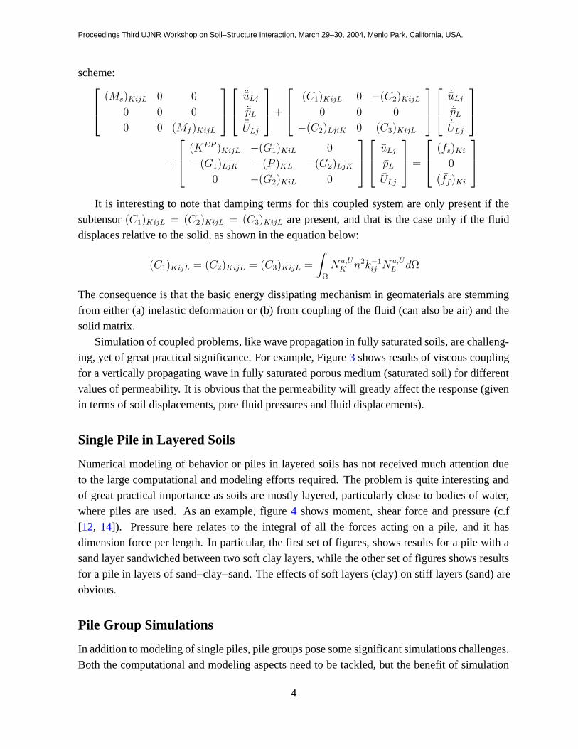
Simulation of coupled problems, like wave propagation in fully saturated soils, are challeng-ing, yet of great practical significance. For example, Figure 3 shows results of viscous couplingfor a vertically propagating wave in fully saturated porous medium (saturated soil) for differentvalues of permeability. It is obvious that the permeability will greatly affect the response (givenin terms of soil displacements, pore fluid pressures and fluid displacements).
Single Pile in Layered Soils
Numerical modeling of behavior or piles in layered soils has not received much attention dueto the large computational and modeling efforts required. The problem is quite interesting andof great practical importance as soils are mostly layered, particularly close to bodies of water,where piles are used. As an example, figure 4 shows moment, shear force and pressure (c.f[12, 14]). Pressure here relates to the integral of all the forces acting on a pile, and it hasdimension force per length. In particular, the first set of figures, shows results for a pile with asand layer sandwiched between two soft clay layers, while the other set of figures shows resultsfor a pile in layers of sand–clay–sand. The effects of soft layers (clay) on stiff layers (sand) areobvious.
Pile Group Simulations
In addition to modeling of single piles, pile groups pose some significant simulations challenges.Both the computational and modeling aspects need to be tackled, but the benefit of simulation
4
Proceedings Third UJNR Workshop on Soil–Structure Interaction, March 29–30, 2004, Menlo Park, California, USA.
0 0.05 0.1 0.15 0.2 0.25 0.3−4
−3
−2
−1
0
1
2x 10
−3
Sol
id D
ispl
acem
ent (
m)
Top node2m from top4m from top6m from top
0 0.05 0.1 0.15 0.2 0.25 0.3−0.5
0
0.5
1
Por
e pr
essu
re (
kPa)
0 0.05 0.1 0.15 0.2 0.25 0.3−4
−3
−2
−1
0
1
2x 10
−3
Time (sec)
Flu
id D
ispl
acem
ent (
m)
0 0.05 0.1 0.15 0.2 0.25 0.3−4
−3
−2
−1
0
1
2x 10
−3
Sol
id D
ispl
acem
ent (
m)
Top node2m from top4m from top6m from top
0 0.05 0.1 0.15 0.2 0.25 0.3−0.5
0
0.5
1
Por
e pr
essu
re (
kPa)
0 0.05 0.1 0.15 0.2 0.25 0.3−4
−3
−2
−1
0
1
2x 10
−3
Time (sec)
Flu
id D
ispl
acem
ent (
m)
Figure 3: Viscous coupling for a vertically propagating wave in two soils with different permeability,
left soil has k = 10−3m/s while the one of the right has k = 10
−5m/s.
−1000 0 1000 2000−10
−8
−6
−4
−2
0
2
SOFT CLAY
Cu = 21.7 kPa
−1.718
SAND
φ = 37.1o
−3.436
SOFT CLAY
Cu = 21.7 kPa
Bending Moment (kN.m)
Dep
th (
m)
−400 −200 0 200 400 600−10
−8
−6
−4
−2
0
2
Shear Force (kN)0 200 400
−10
−8
−6
−4
−2
0
2
Lateral Resistance (kN/m)−1000 0 1000 2000
−10
−8
−6
−4
−2
0
2
SAND
φ = 37.1o
−1.718
SOFT CLAY
Cu = 21.7 kPa
−3.436
SAND
φ = 37.1o
Bending Moment (kN.m)
Dep
th (
m)
−400 −200 0 200 400 600−10
−8
−6
−4
−2
0
2
Shear Force (kN)−100 0 100 200 300
−10
−8
−6
−4
−2
0
2
Lateral Resistance (kN/m)
Figure 4: Moment, shear force and pressure for a single pile in layered soils, left figures, clay–sand–clay
layers, right figures, sand–clay–sand layers.
results to practical problems can be significant. For example, Figure 5 shows the numericallygenerated interaction P-Y curves for piles in a 4x3 pile group (c.f [13]). It is obvious from thispicture that one cannot simply scale back the single pile load deformation response to analyzepile groups.
5

Proceedings Third UJNR Workshop on Soil–Structure Interaction, March 29–30, 2004, Menlo Park, California, USA.
Figure 5: Load displacement interaction diagrams for piles in a pile group.
Dynamic SFS Interaction Modeling
One of the basis for seismic analysis of soil–foundation–structure (SFS) system is appropriateformulation and implementation. The finite size of finite element models introduces many prob-lems, including the input of seismic motions, trapping of wave energy in the finite size model tolist just a few. The recently developed Domain Reduction Method (DRM) for elastic problems[2, 15] is used and adapted for SFS interaction problems. One of the best features of the DRMis that in addition to being applicable to elastic problems, close inspection of the formulationshows that it can be applied to inelastic problems as well. Formulation and implementation de-tails are given in [4]. Figure 6 shows the application of the DRM to SFS problems. The seismicwave field (free field) obtained using some of the available methods, including closed form so-lutions (Green’s functions or large scale geophysical simulations), are used to provide input forthe DRM. The input requires displacements and accelerations on a single layer of elements thatcompletely encompasses the inelastic domain with the SFS system. The effective forces that areused to load the system are then
Peffi
Peffb
P effe
=
0
−MΩ+
be u0e − KΩ+
be u0e
MΩ+
eb u0b + KΩ+
eb u0b
Seismic amplification of local, soft soil sites has been reported many times, yet robust andaccurate 3D simulation techniques have not been fully developed to help analyze SFS interactionproblems. For example, Figure 7, obtained by using our DRM implementation in OpenSees,
6

Proceedings Third UJNR Workshop on Soil–Structure Interaction, March 29–30, 2004, Menlo Park, California, USA.
Fault
Plastic (Soil) "Bowls"
Figure 6: Seismic SFS interaction using large scale geophysical wave propagation and the DRM (soil
islands) to assess the behavior of a bridge during an earthquake.
shows vertical wave propagation through stiff (dense sand) and soft (soft clay) soils subject to thesame earthquake. The result shows that the soft soil site has an increase in surface deformationof 3.5 times than that one of the stiff site.
0 5 10 15 20 25 30 35 40
0.0000−38.0
0.0077−30.0
0.0783−28.0
0.0791−20.0
0.0844−16.0
0.0878−12.0
0.1248 −8.0
0.1800 −4.0
0.1946 0.0
Time (s)
Dis
plac
emen
t (m
)
Z(m) Max
0 5 10 15 20 25 30 35 40
0.0000−38.0
0.0224−30.0
0.0879−28.0
0.1102−20.0
0.1161−16.0
0.1227−12.0
0.3961 −8.0
0.6258 −4.0
0.6928 0.0
Time (s)
Dis
plac
emen
t (m
)
Z(m) Max
Figure 7: Seismic wave propagation resulting from the same earthquake acting on a stiff and soft soil
site.
SFS Case Study
A simple case study was performed in order to investigate SFS interaction effects during earth-quakes (eg. Jeremic et al. [3]). A simplified SFS model, using soil springs was used to illustratebeneficial and detrimental effects of SFS interaction on performance of the structure. The pro-totype structure is a typical bent of the I–880 highway structure in Oakland, CA. The modelconsists of inelastic fiber column–beams to represent the bridge piers where much of the in-elastic behavior is expected to occur, elastic column–beams to represent the deck and equivalentzero-length foundation springs to represent the soil-foundation system. Figure 8 shows the framemodels, one without and one with the SFS interaction. Foundation springs were obtained from
7

Proceedings Third UJNR Workshop on Soil–Structure Interaction, March 29–30, 2004, Menlo Park, California, USA.
∆∆F F
x
z
x
z
yy
Figure 8: Two frame models for the Bent #16,fully £xed and the model with soil springs.
a detailed 3D finite element model of the pile group foundation system using elastic soil prop-erties. It is noted that the inelastic analysis of soil–foundation system was also performed fora limited number of load cases and it was shown that, at least for small deformations expectedhere, the response can be very well approximated with elastic soil behavior. The foundationsystem consists of a 5 × 5 pile groups connected with a massive pile cap. The piles are madeof reinforced concrete and reside in a steel shell with a diameter of 0.6m. The schematic figureof the pile cap, the piles and the finite element mesh for the soil–foundation system is show inFigure 9.
a)
7.2
0.6 1.5 1.5 1.5 1.5 0.6
7.2
21.2
1.5
0.60.60.60.60.6 b)
Figure 9: (a) Schematics of the pile cap and the piles. (b) Finite element mesh for soil foundation system.
A uniform hazard spectra for SD (soil) site conditions was derived for a site in Oaklandwhich represents an event with a 10 % probability of exceedance in 50 years. The hazard isdominated by earthquakes on the Hayward fault which is located about 7 km east of the I–880 site. The ground motion model of Abrahamson and Silva [1] was used in generating thespectra (Somerville and Collins [10]). The spectra contains rupture directivity effects whichwere represented in the probabilistic hazard analysis using the empirical model proposed bySomerville et al. [11]. The spectra were generated for both fault-parallel (FP) and fault-normal(FN) directions. Three time histories were selected: two from the modified suite of Loma Prieta
8

Proceedings Third UJNR Workshop on Soil–Structure Interaction, March 29–30, 2004, Menlo Park, California, USA.
motions (recorded at Gilroy and Corralitos) and one from Kobe. Detailed description of groundmotion generation is given by Jeremic et al. [3]
The main feature in evaluation of the two bent models is in different behavior of the samebent for chosen input motions. Presented here are result from two Loma Prieta motions (Corral-itos and Gilroy). The effects of SFS interaction are considered to be beneficial to the structureunder the following conditions:
• There are no significant permanent deformations in the structure resulting from yieldingof the pier, or
• The energy dissipation (hysteretic loops) of the system with SFS interaction is smallerthan that with fixed foundation, leading to the conclusion that there is less damage to thestructure.
If any of the above criteria is not fulfilled, it is assumed that SFS interaction is detrimentalto the structure behavior. Presented here are two examples of bent behavior, one representingbeneficial effects and one for detrimental effects of SFS interaction. Figure 10 shows behaviorof the bent subjected to the scaled Corralitos record. This record was scaled to match the hazardspectra at a period of 0.77 sec. As is evident from the spectra shown in Figure 10, the demandsimposed by the earthquake are more significant in the short period range, hence the fixed basemodel experiences higher demands than the model with SFS interaction. Both SFS and non SFSinteraction results show small permanent deformation (of the order of one to two centimeters).However, the hysteretic loops of the model considering SFS interaction effects are much smallerthen those of the non SFS interaction model thus suggesting much smaller levels of damage forthe SFS interaction model. The results in Figure 11, on the other hand, clearly indicate that
a)
Spring ModelFixed Model
0.5
0.4
0.3
0.2
0.1
0
−0.1
−0.2
−0.30 5 10 15 20 25 30 35 40
Time (Sec)
Hor
izan
tal D
ispl
acem
ent (
m)
b)−0.3 −0.2 −0.1 0 0.1 0.2 0.3 0.4 0.5
Displacement (m)
Fixed ModelSpring model
x 1066
4
2
0
−2
−4
−6
−8
Shea
r Fo
rce
(N)
Figure 10: LP–Corralitos Record : a) displacement time history for fixed and spring supported models,
b) horizontal displacement vs shear force for fixed and SFS interaction models.
the SFS interaction model subjected to scaled Gilroy earthquake is dissipating more energy and
9

Proceedings Third UJNR Workshop on Soil–Structure Interaction, March 29–30, 2004, Menlo Park, California, USA.
also being subjected to larger deformations than the non–SFS interaction model. The spectraldemands are initially higher in the short period range for this record, however, it is likely thatthe fixed base model moves into a region of slightly lower demands (just beyond 0.5 seconds)since the degree of inelasticity is not severe. The shift in the period from 1.24 seconds of theSFS interaction model takes it into a region of increased demand thus causing higher drifts.
a)
Hor
izan
tal D
ispl
acem
ent (
m)
0.3
0.2
0.1
0
−0.1
−0.2
−0.30 5 10 15 20 25 30
Time (Sec)35 40 45 50
Spring ModelFixed Model
b)
She
ar F
orce
(N
)
x 10
−0.3 −0.2 −0.1 0 0.1 0.2 0.3Displacement (m)
Fixed ModelSpring model
6
4
2
0
−2
−4
−6
−8
6
Figure 11: LP–Gilroy Record: a) displacement time history for fixed and SFS interaction models, b)
horizontal displacement vs shear force for £xed and SFS interaction models.
Summary
The NEESgrid computational simulation platform OpenSees is a very versatile simulation tool.The selected examples, developed mostly within the computational geomechanics group at UCDshow part of this versatility. In addition to that, OpenSees features a number of other models,elements, solutions procedures, making it one of the most useful simulations tools (platforms)available today.
Acknowledgment
This work was supported in part by a number of grants. We list them bellow. Earthquake En-gineering Research Centers Program of the National Science Foundation under Award NumberEEC-9701568 (cognizant program director Dr. Joy Pauschke); Civil and Mechanical Systemprogram, Directorate of Engineering of the National Science Foundation, under Award NSF-CMS-0337811 (cognizant program director Dr. Steve McCabe) and NSF–CMS–0324661 (cog-nizant program director Dr. Richard Fragaszy); California Environmental Protection Agencyunder Award Cal–EPA 02-002-96V (cognizant program director Ms. Stacey Patenaude).
10

Proceedings Third UJNR Workshop on Soil–Structure Interaction, March 29–30, 2004, Menlo Park, California, USA.
The author also wishes to acknowledge colleagues and current and former students who havecontributed to the described work: Professors Sashi Kunnath, Gregory Fenves, Zhaohui Yangand Feng Xiong, Dr. Frank McKenna, and students Xiaoyan Wu, Ritu Jain, James Putnam, QingLiu, Jinxiu Liao, Kallol Sett, Zhao Cheng, Matthias Preisig, Guanzhou Jie, Vlado Vukadin andIan Tucker.
References
[1] N. A. Abrahamson and W. J. Silva. Empirical response spectral attenuation relations forshallow crustal earthqaueks. Seismological Research Letters, 68:94–127, 1997.
[2] Jacobo Bielak, Kostas Loukakis, Yoshaiki Hisada, and Chaiki Yoshimura. Domain re-duction method for three–dimensional earthquake modeling in localized regions. part I:Theory. Bulletin of the Seismological Society of America, 93(2):817–824, 2003.
[3] Boris Jeremic, Sashi Kunnath, and Feng Xiong. Influence of soil–structure interaction onseismic response of bridges. International Journal for Engineering Structures, 26(3):391–402, February 2003.
[4] Boris Jeremic and Jinxiu Liao. Domain reduction method for soil-foundation-structure in-teraction analysis. Technical Report UCD-CGM 01-2004, University of California, Davis,January 2004.
[5] Boris Jeremic and Qing Liu. Fully coupled, solid–fluid formulation and implementation.Technical Report UCD-CGM 02-2004, University of California, Davis, March 2004.
[6] Boris Jeremic and Zhaohui Yang. Template elastic–plastic computations in geomechan-ics. International Journal for Numerical and Analytical Methods in Geomechanics,26(14):1407–1427, 2002.
[7] M. T. Manzari and Y. F. Dafalias. A critical state two–surface plasticity model for sands.Geotechnique, 47(2):255–272, 1997.
[8] William L. Oberkampf, Timothy G. Trucano, and Charles Hirsch. Verification, validationand predictive capability in computational engineering and physics. In Proceedings of
the Foundations for Verif ication and Validation on the 21st Century Workshop, pages 1–74, Laurel, Maryland, October 22-23 2002. Johns Hopkins University / Applied PhysicsLaboratory.
[9] Patrick J. Roache. Verif ication and Validation in Computational Science and Engineering.hermosa publishers, 1998. ISBN 0-913478-08-3.
11

Proceedings Third UJNR Workshop on Soil–Structure Interaction, March 29–30, 2004, Menlo Park, California, USA.
[10] Paul Somerville and Nancy Collins. Ground motions time histories for the I-880 bridge,Oakland. Report to peer methodology testbeds projects, URS Corporation, 2002.
[11] P.G. Somerville, N.F. Smith, R.W Graves, and N.A. Abrahamson. Modification of em-pirical strong ground motion attenuations to include the amplitude and duration effects ofrupture directivity. Seismological Research Letters, 68:199–222, 1997.
[12] Zhaohui Yang and Boris Jeremic. Numerical analysis of pile behaviour under lateral loadsin layered elastic-plastic soils. International Journal for Numerical and Analytical Meth-
ods in Geomechanics, 26(14):1385–1406, 2002.
[13] Zhaohui Yang and Boris Jeremic. Numerical study of the effective stiffness for pilegroups. International Journal for Numerical and Analytical Methods in Geomechanics,27(15):1255–1276, Dec 2003.
[14] Zhaohui Yang and Boris Jeremic. Soil layering effects on lateral pile behavior. In print in
ASCE Journal of Geotechnical and Geoenvironmental Engineering, July 2004.
[15] Chaiki Yoshimura, Jacobo Bielak, and Yoshaiki Hisada. Domain reduction method forthree–dimensional earthquake modeling in localized regions. part II: Verification and ex-amples. Bulletin of the Seismological Society of America, 93(2):825–840, 2003.
[16] O. C. Zienkiewicz and T. Shiomi. Dynamic behaviour of saturated porous media; the gen-eralized Biot formulation and its numerical solution. International Journal for Numerical
Methods in Engineering, 8:71–96, 1984.
12
Related Documents