ETSITS 100 596 V8.6.0 (2000-11) Technical Specification Di gi tal ce llu lar telecommun icati ons system (Pha se 2+ ); Base Sta ti on Controll er - Base Transceiver Sta tion (B SC - BTS ) interface; Layer 3 specification (3 GPP TS 08.58 version 8.6.0 Release 1999) GLOBAL SYSTEM FOR MOBILE COMMUNICATIONS R

Welcome message from author
This document is posted to help you gain knowledge. Please leave a comment to let me know what you think about it! Share it to your friends and learn new things together.
Transcript

7/27/2019 A-Bis Interface Layer3
http://slidepdf.com/reader/full/a-bis-interface-layer3 1/83
ETSI TS 100 596 V8.6.0 (2000-11)
Technical Specification
Digital cellular telecommunications system (Phase 2+);Base Station Controller - Base Transceiver Station
(BSC - BTS) interface;Layer 3 specification
(3GPP TS 08.58 version 8.6.0 Release 1999)
GLOBAL SYSTEM FOR
MOBILE COMMUNICATIONS
R

7/27/2019 A-Bis Interface Layer3
http://slidepdf.com/reader/full/a-bis-interface-layer3 2/83
1
ETSI
ETSI TS 100 596 V8.6.0 (2000-11)3GPP TS 08.58 version 8.6.0 Release 1999
ReferenceRTS/TSGG-020858Q8R3
Keywords
GSM
ETSI
650 Route des LuciolesF-06921 Sophia Antipolis Cedex - FRANCE
Tel.: +33 4 92 94 42 00 Fax: +33 4 93 65 47 16
Siret N°348 623 562 00017 - NAF 742 CAssociation à but non lucratif enregistrée à laSous-Préfecture de Grasse (06) N°7803/88
Important notice
Individual copies of the present document can be downloaded from:http://www.etsi.org
The present document may be made available in more than one electronic version or in print. In any case of existing orperceived difference in contents between such versions, the reference version is the Portable Document Format (PDF).
In case of dispute, the reference shall be the printing on ETSI printers of the PDF version kept on a specific network drivewithin ETSI Secretariat.
Users of the present document should be aware that the document may be subject to revision or change of status.Information on the current status of this and other ETSI documents is available at http://www.etsi.org/tb/status /
If you find errors in the present document, send your comment to:[email protected]
Copyright Notification
No part may be reproduced except as authorized by written permission.The copyright and the foregoing restriction extend to reproduction in all media.
© European Telecommunications Standards Institute 2000.
All rights reserved.

7/27/2019 A-Bis Interface Layer3
http://slidepdf.com/reader/full/a-bis-interface-layer3 3/83
2
ETSI
ETSI TS 100 596 V8.6.0 (2000-11)3GPP TS 08.58 version 8.6.0 Release 1999
Intellectual Property Rights
IPRs essential or potentially essential to the present document may have been declared to ETSI. The information
pertaining to these essential IPRs, if any, is publicly available for ETSI members and non-members, and can be found
in ETSI SR 000 314: "Intellectual Property Rights (IPRs); Essential, or potentially Essential, IPRs notified to ETSI inrespect of ETSI standards" , which is available from the ETSI Secretariat. Latest updates are available on the ETSI Web
server (http://www.etsi.org/ipr).
Pursuant to the ETSI IPR Policy, no investigation, including IPR searches, has been carried out by ETSI. No guaranteecan be given as to the existence of other IPRs not referenced in ETSI SR 000 314 (or the updates on the ETSI Web
server) which are, or may be, or may become, essential to the present document.
Foreword
This Technical Specification (TS) has been produced by the ETSI 3rd Generation Partnership Project (3GPP).
The present document may refer to technical specifications or reports using their 3GPP identities, UMTS identities orGSM identities. These should be interpreted as being references to the corresponding ETSI deliverables.
The cross reference between GSM, UMTS, 3GPP and ETSI identities can be found under www.etsi.org/key .

7/27/2019 A-Bis Interface Layer3
http://slidepdf.com/reader/full/a-bis-interface-layer3 4/83
ETSI
ETSI TS 100 596 V8.6.0 (2000-11)33GPP TS 08.58 version 8.6.0 Release 1999
Contents
Foreword............................................................................................................................................................ 7
1 Scope ....................................................................................................................................................... 81.1 References ................................................... ............................................................ ...........................................8
1.2 Abbreviations ........................................................ ......................................................... ....................................9
2 Protocol model ........................................................................................................................................ 9
3 Radio Link Layer Management Procedures .......................................................................................... 103.1 Link establishment indication........................ ...................................................................... .............................10
3.2 Link establishment request ......................................................... ..................................................... .................11
3.3 Link release indication ..................................................................... ....................................................... .........11
3.4 Link release request...................................................... ........................................................... .........................11
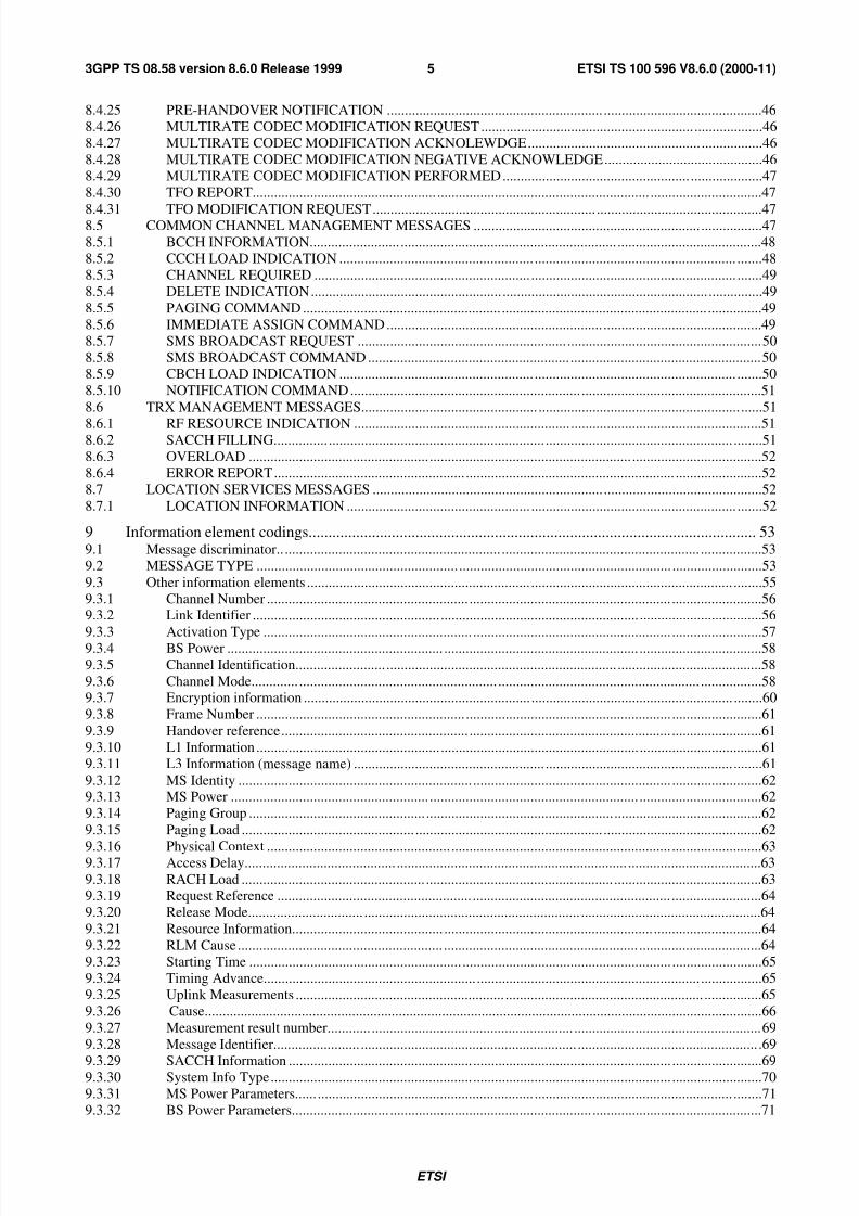
3.5 Transmission of a transparent L3-Message in acknowledged mode ................................................... .............123.6 Reception of a transparent L3-Message in acknowledged mode.................................... ..................................12
3.7 Transmission of a transparent L3-Message in unacknowledged mode ............................................. ...............12
3.8 Reception of a transparent L3-Message in unacknowledged mode................................. .................................12
3.9 Link error indication.............................................................. .......................................................... .................13
4 Dedicated channel management procedures.......................................................................................... 134.1 Channel activation ............................................................... ............................................................ .................13
4.1.1 Signalling Procedure......................................................... ......................................................... .................13
4.1.2 Activation for Intra-Cell Channel Change ........................................................ ..........................................14
4.1.3 Activation for Asynchronous Handover ................................................................ .....................................15
4.1.4 Activation for Synchronous Handover..................................................... ...................................................15
4.1.5 Activation for Secondary Channels in Multislot Configuration.............................................................. ....15
4.1.6 Channel reactivation .............................................................. .................................................... .................15
4.2 Channel MODE MODIFY ............................................................... ......................................................... .......16
4.3 Handover detection........................ ............................................................ .......................................................16
4.4 Start of encryption .......................................................... ......................................................... .........................164.5 Measurement reporting..................... ................................................................. .............................................. .17
4.5.1 Basic measurement reporting........................................................... ................................................... ........18
4.5.2 Measurement pre-processing ................................................. ..................................................... ................18
4.5.2.1 Pre-processing configuration.......................... ....................................................... ................................18
4.5.2.2 Pre-processed measurement reporting....................... ........................................................ ....................194.5.3 Extended measurement reporting................................ ........................................................... .....................19
4.6 Deactivate SACCH......................................... ................................................................. .................................20
4.7 Radio channel release ................................................................. ..................................................... .................20
4.8 MS power control .................................................. ........................................................ ...................................20
4.9 Transmission power control ....................................................... ...................................................... ................21
4.10 Connection failure .......................................................... ......................................................... .........................214.11 Physical context request ...................................................... ............................................................ .................22
4.12 SACCH information modify ................................................... ......................................................... ................224.13 Talker detection.............................................................. ........................................................ ..........................22
4.14 Listener detection ....................................................... ............................................................ ..........................22
4.15 Remote Codec Configuration .......................................................... ......................................................... ........23
4.16 Round Trip Delay Report ................................................. ....................................................... .........................234.17 Pre-handover Warning.................................... .................................................... ..............................................23
4.18 MultiRate Codec Configuration Change .................................................. ........................................................23
4.19 MultiRate Codec Configuration Change Performed......................................... ................................................24
4.20 TFO Report........................................................... .......................................................... ..................................24
4.21 TFO Modification Request..... ............................................................ ...................................................... ........25
5 Common channel management procedures........................................................................................... 255.1 Channel request by MS .............................................................. ..................................................... .................25
5.2 Paging...............................................................................................................................................................255.3 Delete indication................................ .......................................................................... .....................................265.4 CCCH load indication ............................................................. ........................................................ .................26
5.5 Broadcast information modify.......... ................................................................. ...............................................26

7/27/2019 A-Bis Interface Layer3
http://slidepdf.com/reader/full/a-bis-interface-layer3 5/83
ETSI
ETSI TS 100 596 V8.6.0 (2000-11)43GPP TS 08.58 version 8.6.0 Release 1999
5.6 Short Message Cell Broadcast............................................................... ................................................... ........26
5.7 IMMEDIATE ASSIGNMENT............................................. ............................................................. ...............29
5.8 Notification.......................................................................................................................................................30
6 TRX management procedures ............................................................................................................... 306.1 Radio resource indication ....................................................... ......................................................... .................30
6.2 SACCH filling information modify.......................... ................................................................. .......................31
6.3 Flow control ...................................................... ............................................................. ..................................31
6.4 Error reporting................................................... .................................................... ...........................................32
6a Location services procedures ................................................................................................................ 326a.1 LLP message transport ...................................................... ...................................................... .........................32
7 Error handling........................................................................................................................................ 327.1 General ...................................................... ............................................................ ...........................................32
7.2 Message discriminator error ............................................... ............................................................. .................337.3 Message type error ................................................ ....................................................... ....................................33
7.4 Message sequence error............. ....................................................... ....................................................... .........33
7.5 General information element errors................... ...................................................................... .........................33
7.6 Mandatory information element errors ......................................................... ....................................................33
7.7 Optional information element errors .......................................................... ......................................................337.8 Conditional information element errors..................................................... .......................................................34
8 Message formats and contents............................................................................................................... 348.1 Transparent messages...................... ................................................................. ............................................... .35
8.2 Non-transparent messages (BSC-BTS specific messages)............................................................ ...................35
8.3 Radio link layer management messages................................................... ........................................................35
8.3.1 DATA REQUEST ............................................................... ....................................................... ................36
8.3.2 DATA INDICATION........................................................... ...................................................... ................36
8.3.3 ERROR INDICATION.................. ........................................................ .....................................................36
8.3.4 ESTABLISH REQUEST ............................................................. ....................................................... ........36
8.3.5 ESTABLISH CONFIRM..... ............................................................ ...........................................................37
8.3.6 ESTABLISH INDICATION........................................... ........................................................ ....................37
8.3.7 RELEASE REQUEST ............................................................... ......................................................... ........37
8.3.8 RELEASE CONFIRM........... ............................................................ .........................................................37
8.3.9 RELEASE INDICATION........................................................... ........................................................ ........37
8.3.10 UNIT DATA REQUEST ............................................................. ....................................................... ........38
8.3.11 UNIT DATA INDICATION ......................................................... ...................................................... .......38
8.4 DEDICATED CHANNEL MANAGEMENT MESSAGES................................................................ ............38
8.4.1 CHANNEL ACTIVATION........................................................... ...................................................... .......39
8.4.2 CHANNEL ACTIVATION ACKNOWLEDGE.............................................................. ..........................40
8.4.3 CHANNEL ACTIVATION NEGATIVE ACKNOWLEDGE...................................................................40
8.4.4 CONNECTION FAILURE INDICATION ................................................................... .............................41
8.4.5 DEACTIVATE SACCH............................................................... ...................................................... ........41
8.4.6 ENCRYPTION COMMAND......................................................... ..................................................... .......41
8.4.7 HANDOVER DETECTION................................................................. ......................................................41
8.4.8 MEASUREMENT RESULT ................................................................ ......................................................41
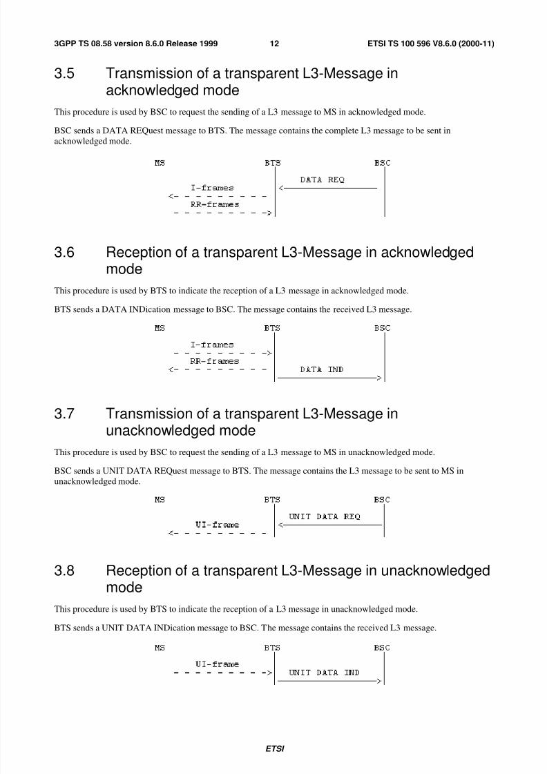
8.4.9 MODE MODIFY................................................................ ........................................................ ................42
8.4.10 MODE MODIFY ACKNOWLEDGE .................................................................... ....................................428.4.11 MODE MODIFY NEGATIVE ACKNOWLEDGE ................................................................. ..................43
8.4.12 PHYSICAL CONTEXT REQUEST............................................................ ...............................................43
8.4.13 PHYSICAL CONTEXT CONFIRM ........................................................... ...............................................43
8.4.14 RF CHANNEL RELEASE .......................................................... ........................................................ .......43
8.4.15 MS POWER CONTROL..................................................... ........................................................ ...............43
8.4.16 BS POWER CONTROL................. ............................................................ ................................................448.4.17 PREPROCESS CONFIGURE ................................................................. ...................................................44
8.4.18 PREPROCESSED MEASUREMENT RESULT .............................................................. .........................44
8.4.19 RF CHANNEL RELEASE ACKNOWLEDGE ................................................................. ........................44
8.4.20 SACCH INFO MODIFY ............................................................... ..................................................... ........44
8.4.21 TALKER DETECTION ....................................................... ....................................................... ...............458.4.22 LISTENER DETECTION ............................................................... ................................................... ........458.4.23 REMOTE CODEC CONFIGURATION REPORT.......................... ..........................................................45
8.4.24 ROUND TRIP DELAY REPORT........................................................... ...................................................46
7/27/2019 A-Bis Interface Layer3
http://slidepdf.com/reader/full/a-bis-interface-layer3 6/83
ETSI
ETSI TS 100 596 V8.6.0 (2000-11)53GPP TS 08.58 version 8.6.0 Release 1999
8.4.25 PRE-HANDOVER NOTIFICATION ............................................................ ............................................46
8.4.26 MULTIRATE CODEC MODIFICATION REQUEST ........................................................... ...................46
8.4.27 MULTIRATE CODEC MODIFICATION ACKNOLEWDGE................................................ .................46
8.4.28 MULTIRATE CODEC MODIFICATION NEGATIVE ACKNOWLEDGE............................................46
8.4.29 MULTIRATE CODEC MODIFICATION PERFORMED.................................................... ....................47
8.4.30 TFO REPORT................................................... ........................................................... ...............................47
8.4.31 TFO MODIFICATION REQUEST.............................................................. ..............................................478.5 COMMON CHANNEL MANAGEMENT MESSAGES ............................................................... .................47
8.5.1 BCCH INFORMATION......................... ............................................................ ........................................48
8.5.2 CCCH LOAD INDICATION ...................................................... ........................................................ .......48
8.5.3 CHANNEL REQUIRED ............................................................ ......................................................... .......49
8.5.4 DELETE INDICATION..................................................... ......................................................... ...............49
8.5.5 PAGING COMMAND ....................................................... ......................................................... ...............49
8.5.6 IMMEDIATE ASSIGN COMMAND............................................................ ............................................49
8.5.7 SMS BROADCAST REQUEST .......................................................... ......................................................50
8.5.8 SMS BROADCAST COMMAND ........................................................ .....................................................50
8.5.9 CBCH LOAD INDICATION ...................................................... ........................................................ .......50
8.5.10 NOTIFICATION COMMAND................................................................ ..................................................51
8.6 TRX MANAGEMENT MESSAGES................................................. ........................................................ ......51
8.6.1 RF RESOURCE INDICATION ............................................................ .....................................................518.6.2 SACCH FILLING............... ............................................................ .................................................... ........51
8.6.3 OVERLOAD .................................................. ........................................................ ....................................52
8.6.4 ERROR REPORT..................................................... .......................................................... ........................52
8.7 LOCATION SERVICES MESSAGES ................................................................ ............................................52
8.7.1 LOCATION INFORMATION ................................................... ......................................................... .......52
9 Information element codings................................................................................................................. 539.1 Message discriminator.............................................................. ....................................................... .................53
9.2 MESSAGE TYPE ........................................................ ........................................................... .........................53
9.3 Other information elements .............................................................. ........................................................ ........55
9.3.1 Channel Number ........................................................ ........................................................ .........................569.3.2 Link Identifier .................................................... ....................................................... ..................................56
9.3.3 Activation Type .......................................................... ....................................................... .........................579.3.4 BS Power ............................................................ ...................................................... ..................................58
9.3.5 Channel Identification......................... ................................................................ ........................................58
9.3.6 Channel Mode............. ....................................................... ........................................................ .................589.3.7 Encryption information ............................................................... ........................................................ ........60
9.3.8 Frame Number .......................................................... ......................................................... .........................61
9.3.9 Handover reference.................................................... ........................................................ .........................61
9.3.10 L1 Information................................................... ....................................................... ..................................61
9.3.11 L3 Information (message name) ..................................................... .................................................... ........61
9.3.12 MS Identity ................................................................. ....................................................... .........................629.3.13 MS Power ....................................................... .......................................................... ..................................62
9.3.14 Paging Group ................................................. .................................................... .........................................62
9.3.15 Paging Load ................................................ .................................................... ............................................62
9.3.16 Physical Context ................................................... ............................................................. .........................639.3.17 Access Delay.......................................... ................................................................ .....................................63
9.3.18 RACH Load ................................................... .................................................... .........................................639.3.19 Request Reference ...................................................... ....................................................... .........................64
9.3.20 Release Mode................................ ............................................................ ..................................................64
9.3.21 Resource Information.......................................... .......................................................... ..............................64
9.3.22 RLM Cause ......................................................... ...................................................... ..................................64
9.3.23 Starting Time ........................................................... .......................................................... .........................65
9.3.24 Timing Advance........................................................... .............................................................. .................65
9.3.25 Uplink Measurements .......................................................... ....................................................... ................65
9.3.26 Cause...........................................................................................................................................................66
9.3.27 Measurement result number............ ........................................................ ....................................................69
9.3.28 Message Identifier........................ ............................................................ .................................................. .69
9.3.29 SACCH Information ................................................... ....................................................... .........................699.3.30 System Info Type........................................................ ....................................................... .........................70
9.3.31 MS Power Parameters...... ............................................................ ....................................................... ........71
9.3.32 BS Power Parameters........................... ........................................................ ...............................................71

7/27/2019 A-Bis Interface Layer3
http://slidepdf.com/reader/full/a-bis-interface-layer3 7/83
ETSI
ETSI TS 100 596 V8.6.0 (2000-11)63GPP TS 08.58 version 8.6.0 Release 1999
9.3.33 Pre-processing Parameters .................................................. ........................................................ ................71
9.3.34 Pre-processed Measurements................... ............................................................ .......................................72
9.3.35 Full Immediate Assign Info .......................................................... ...................................................... ........72
9.3.36 SMSCB Information ............................................................ ....................................................... ................72
9.3.37 MS Timing Offset .................................................. ............................................................ .........................72
9.3.38 Erroneous Message ........................................................ .................................................... .........................72
9.3.39 Full BCCH Information (message name) .............................................................. .....................................739.3.40 Channel Needed...................................................... ........................................................... .........................73
9.3.41 CB Command type................................... ........................................................ ...........................................73
9.3.42 SMSCB Message ................................................... ............................................................ .........................74
9.3.43 CBCH Load Information .................................................... ........................................................ ................74
9.3.44 SMSCB Channel Indicator.......................................................... ........................................................ ........75
9.3.45 Group call reference........................................ ........................................................... .................................75
9.3.46 Channel description .......................................................... ......................................................... .................75
9.3.47 NCH DRX information....................................................... ........................................................ ................75
9.3.48 Command indicator............................ ............................................................ .............................................76
9.3.49 eMLPP Priority ............................................................ ...................................................... .........................76
9.3.50 UIC .......................................................... ........................................................... ........................................76
9.3.51 Main channel reference... ................................................................. ................................................... ........76
9.3.52 MultiRate configuration............................................................ .......................................................... ........779.3.53 MultiRate Control ....................................................... ....................................................... .........................77
9.3.54 Supported Codec Types .................................................... .................................................. ........................77
9.3.55 Codec Configuration............................................................ ...................................................... .................79
9.3.56 Round Trip Delay ...................................................... ........................................................ .........................79
9.3.57 TFO Status ............................................................. ............................................................ .........................80
9.3.58 LLP APDU ....................................................... ......................................................... .................................80
Annex A (informative): Change history .............................................................................................. 81

7/27/2019 A-Bis Interface Layer3
http://slidepdf.com/reader/full/a-bis-interface-layer3 8/83
ETSI
ETSI TS 100 596 V8.6.0 (2000-11)73GPP TS 08.58 version 8.6.0 Release 1999
Foreword
This Technical Specification has been produced by the 3rd
Generation Partnership Project (3GPP).
The contents of the present document are subject to continuing work within the TSG and may change following formalTSG approval. Should the TSG modify the contents of the present document, it will be re-released by the TSG with anidentifying change of release date and an increase in version number as follows:
Version x.y.z
where:
x the first digit:
1 presented to TSG for information;
2 presented to TSG for approval;
3 or greater indicates TSG approved document under change control.
y the second digit is incremented for all changes of substance, i.e. technical enhancements, corrections,
updates, etc.
z the third digit is incremented when editorial only changes have been incorporated in the document.

7/27/2019 A-Bis Interface Layer3
http://slidepdf.com/reader/full/a-bis-interface-layer3 9/83
ETSI
ETSI TS 100 596 V8.6.0 (2000-11)83GPP TS 08.58 version 8.6.0 Release 1999
1 Scope
The use and general aspects of the Base Station Controller (BSC) to Base Station Transceiver (BTS) interface (the A-
bis interface) are given in 3GPP TS 08.51.
This Technical Specification (TS) specifies the general structure of layer 3 and traffic management procedures andmessages used on the A-bis interface to support signalling procedures as defined in 3GPP TS 04.08. Support for
Location Services (LCS) related signalling, as defined in 3GPP TS 03.71, is also included. 3GPP TS 03.71 identifies
new A-bis signalling to support BTS-embedded Type B LMUs as well as standalone, Type B LMUs. The standalone
Type B LMU supports the layer 1 and 2 signalling for the A-bis as well as the Location Service message defined in this
specification.
Network management procedures and messages for the A-bis interface are defined in 3GPP TS 08.59.
The functional split between BSC and BTS is defined in 3GPP TS 08.52. The procedures and messages required to
support this split are defined in detail in this TS.
1.1 ReferencesThe following documents contain provisions which, through reference in this text, constitute provisions of the present
document.
• References are either specific (identified by date of publication, edition number, version number, etc.) or
non-specific.
• For a specific reference, subsequent revisions do not apply.
• For a non-specific reference, the latest version applies.
[1] 3GPP TS 01.04: "Digital cellular telecommunications system (Phase 2+); Abbreviations and
acronyms".
[2] 3GPP TS 03.20: "Digital cellular telecommunications system (Phase 2+); Security related network
functions".
[2a] 3GPP TS 03.71: “Digital cellular telecommunications system (Phase 2+); Location Services(LCS); (Functional description) - Stage 2”
[3] 3GPP TS 04.04: "Digital cellular telecommunications system (Phase 2+); Layer 1; General
requirements".
[4] 3GPP TS 04.05: "Digital cellular telecommunications system (Phase 2+); Data Link (DL) layer;
General aspects".
[5] 3GPP TS 04.06: "Digital cellular telecommunications system (Phase 2+); Mobile Station - BaseStation System (MS - BSS) interface; Data Link (DL) layer specification".
[6] 3GPP TS 04.08: "Digital cellular telecommunications system (Phase 2+); Mobile radio interface
layer 3 specification".
[7] 3GPP TS 04.12: "Digital cellular telecommunications system (Phase 2+); Short Message Service
Cell Broadcast (SMSCB) support on the mobile radio interface".
[7a] 3GPP TS 04.71: “Digital cellular telecommunications system (Phase 2+); Mobile radio interface
layer 3 Location Services (LCS) specification”.
[8] 3GPP TS 05.02: "Digital cellular telecommunications system (Phase 2+); Multiplexing and
multiple access on the radio path".
[9] 3GPP TS 05.05: "Digital cellular telecommunications system (Phase 2+); Radio transmission and
reception".

7/27/2019 A-Bis Interface Layer3
http://slidepdf.com/reader/full/a-bis-interface-layer3 10/83
ETSI
ETSI TS 100 596 V8.6.0 (2000-11)93GPP TS 08.58 version 8.6.0 Release 1999
[10] 3GPP TS 05.08: "Digital cellular telecommunications system (Phase 2+); Radio subsystem link
control".
[11] 3GPP TS 05.09: "Digital cellular telecommunications system (Phase 2+); Link Adaptation".
[12] 3GPP TS 05.10: "Digital cellular telecommunications system (Phase 2+); Radio subsystem
synchronization".
[13] 3GPP TS 08.06: "Digital cellular telecommunications system (Phase 2+); Signalling transport
mechanism specification for the Base Station System - Mobile-services Switching Centre (BSS -
MSC) interface".
[14] 3GPP TS 08.08: "Digital cellular telecommunications system (Phase 2+); Mobile-services
Switching Centre - Base Station System (MSC - BSS) interface; Layer 3 specification".
[15] 3GPP TS 08.51: "Digital cellular telecommunications system (Phase 2+); Base Station Controller -
Base Transceiver Station (BSC - BTS) interface; General aspects".
[16] 3GPP TS 08.52: "Digital cellular telecommunications system (Phase 2+); Base Station Controller -
Base Transceiver Station (BSC - BTS) interface; Interface principles".
[17] 3GPP TS 08.56: "Digital cellular telecommunications system (Phase 2+); Base Station Controller -Base Transceiver Station (BSC - BTS) interface; Layer 2 specification".
1.2 Abbreviations
Abbreviations used in this TS are listed in 3GPP TS 01.04
2 Protocol model
A model for L3 can be found in figure 2.1.
L2 addressing is made to TRX (or BCF) using the TEI of LAPD. Different L2 links are used for traffic management
messages (RSL, Radio Signalling Link), network management messages (OML, Operation & Maintenance Link) and
L2 management messages (L2ML, Layer 2 Management Link).
For traffic management, two types of signalling messages have been defined:
Transparent Messages: Messages which are forwarded by BTS without interpretation or changes.
Non-Transparent Messages: Messages which are sent only between BSC and BTS and which BTS is acting upon or
which are the results of BTS actions.
In addition, the messages have been grouped into four main groups: Radio Link Layer Management, Dedicated Channel
Management, Common Channel Management and TRX Management messages.
Discrimination between these types and groups is based on the Message Discriminator which is sent as the first octet inall messages. Transparent and non-transparent messages are discriminated by a transparency flag (T-bit) in the Message
Discriminator. Transparent messages are merely forwarded to L2 on the radio interface.
In order to address the relevant radio channel, a Channel Number element is included to support the distribution of
messages to relevant physical channels on the TRX. A Link Identifier element supports the distribution on logical
links/channels on the radio interface (compare the DLCI element of the A interface, 3GPP TS 08.06).
All messages in this GTS are to be transmitted on the A-bis interface using the I format of LAPD, except for
MEASUREMENT RESULT which is sent in UI format.

7/27/2019 A-Bis Interface Layer3
http://slidepdf.com/reader/full/a-bis-interface-layer3 11/83
ETSI
ETSI TS 100 596 V8.6.0 (2000-11)103GPP TS 08.58 version 8.6.0 Release 1999
Chan No
Link
distri-
bution
Other processes within BTS
Traffic Management
Procedures
(08.58)
Transparent
Messages
Non-
Transparent
Messages
Distribution
Network
Management
Procedures
(12.21)
L2
Management
Procedures
To radio
interface
0 62 63
RSL OML L2ML
L3
L2
Figure 2.1/08.58: L3 model
3 Radio Link Layer Management Procedures
This clause describes procedures related to the management of a link layer connection on the radio path.
3.1 Link establishment indication
This procedure is used by BTS to indicate to BSC that a layer 2 link on the radio path has been established in multi-
frame mode at the initiative of an MS. BSC can use this indication to set up an SCCP connection to MSC.
Upon reception of a SABM frame on a link on an active channel, the BTS sends an ESTablish INDication message to
BSC. The message contains the contents of the information field of the SABM frame if present.
The procedure is used in all establishment cases, for all channels and all SAPIs.

7/27/2019 A-Bis Interface Layer3
http://slidepdf.com/reader/full/a-bis-interface-layer3 12/83
ETSI
ETSI TS 100 596 V8.6.0 (2000-11)113GPP TS 08.58 version 8.6.0 Release 1999
3.2 Link establishment request
This procedure is used by BSC to request the establishment of a link layer connection in multi-frame mode on the radio
path.
The procedure is started by BSC sending an ESTablish REQuest message to BTS. BTS then establishes the link by
sending an SABM frame. Upon reception of the acknowledgement (UA-frame) from MS, BTS sends an ESTablishCONFirm message to BSC.
In case of a failure, BTS sends a RELease INDication and an ERRor INDication message to BSC (cf. 3GPP TS 04.06).
3.3 Link release indication
This procedure is used by BTS to indicate to BSC that a link layer connection on the radio path has been released at the
initiative of an MS.
When receiving a DISC frame on a link layer connection in multi-frame mode, BTS sends a RELease INDication
message to BSC. (If the link layer is in idle mode, BTS will send a DM frame to MS but does not notify BSC.)
Collision cases are treated as specified in 3GPP TS 04.06.
3.4 Link release request
This procedure is used by BSC to request the release of a link layer connection on the radio path.
The procedure is started by BSC sending a RELease REQuest message to BTS. BTS then sends a DISC frame to MS.
When it has received the acknowledgement (UA or DM frame), BTS sends a RELease CONFirm message to BSC.
Collision cases are treated as specified in 3GPP TS 04.06.
If BTS has repeated the DISC frame N200 times, BTS sends a RELease INDication and an ERRor INDication message
to BSC (cf. 3GPP TS 04.06).
7/27/2019 A-Bis Interface Layer3
http://slidepdf.com/reader/full/a-bis-interface-layer3 13/83
ETSI
ETSI TS 100 596 V8.6.0 (2000-11)123GPP TS 08.58 version 8.6.0 Release 1999
3.5 Transmission of a transparent L3-Message inacknowledged mode
This procedure is used by BSC to request the sending of a L3 message to MS in acknowledged mode.
BSC sends a DATA REQuest message to BTS. The message contains the complete L3 message to be sent in
acknowledged mode.
3.6 Reception of a transparent L3-Message in acknowledged
modeThis procedure is used by BTS to indicate the reception of a L3 message in acknowledged mode.
BTS sends a DATA INDication message to BSC. The message contains the received L3 message.
3.7 Transmission of a transparent L3-Message inunacknowledged mode
This procedure is used by BSC to request the sending of a L3 message to MS in unacknowledged mode.
BSC sends a UNIT DATA REQuest message to BTS. The message contains the L3 message to be sent to MS in
unacknowledged mode.
3.8 Reception of a transparent L3-Message in unacknowledgedmode
This procedure is used by BTS to indicate the reception of a L3 message in unacknowledged mode.
BTS sends a UNIT DATA INDication message to BSC. The message contains the received L3 message.

7/27/2019 A-Bis Interface Layer3
http://slidepdf.com/reader/full/a-bis-interface-layer3 14/83
ETSI
ETSI TS 100 596 V8.6.0 (2000-11)133GPP TS 08.58 version 8.6.0 Release 1999
3.9 Link error indication
This procedure is used by BTS to indicate an abnormal case such as the following.
- a protocol error as specified in 3GPP TS 04.06, subclauses 5.6.4, 5.7.3 and annex G;
- a link layer failure, i.e. the repetition of an I-frame N200 times without an acknowledgement;
- the repetition of an SABM or DISC frame N200 times without an acknowledgement;
- the reception of an SABM frame in multi-frame established state.
When such an event has occurred, BTS notifies BSC by sending an ERROR INDication message containing the
relevant cause information.
4 Dedicated channel management procedures
4.1 Channel activation
This procedure is used to activate a channel at the BTS for an MS which later will be commanded to this channel by an
IMMediate ASSIGN, an ASSIGN CoMmanD, an ADDitional ASSIGNment; a NOTIFICATION, a CHANNEL
RELEASE (with a Channel description) a HANDOver CoMmanD or a CONFiguration CHange CoMmanD message.
In the handover case, the procedure is used between the target BSC and the target BTS to activate a channel for a
subsequent handover from the old BTS.
4.1.1 Signalling Procedure
BSC determines what channel shall be used and starts up that channel at BTS by sending a CHANnel ACTIVation
message to the relevant TRX. This message contains the reason for the activation (immediate assignment, assignment,
asynchronous/synchronous handover, additional assignment, activation of a secondary channel in a multislotconfiguration), the identification of the channel to be used (channel no) and a complete description of the channel
(full/half rate, speech/data, coding/rate adaption, hopping sequence, encryption key etc.).
If the Encryption Information field is present, the activation is done with ciphering active. If the Encryption Information
element is not present, activation is done without ciphering.
After activating the channel as requested, TRX responds with the CHANnel ACTIVation ACKnowledge message. Thismessage contains the current frame number at BTS. The frame number is used by BSC to determine the Starting Timeparameter to be included in the following assignment message to MS. (A suitable number has to be added to current
frame number to take all possible signalling delays into account).

7/27/2019 A-Bis Interface Layer3
http://slidepdf.com/reader/full/a-bis-interface-layer3 15/83
ETSI
ETSI TS 100 596 V8.6.0 (2000-11)143GPP TS 08.58 version 8.6.0 Release 1999
If the TRX for some reason cannot activate the resource as requested by the CHANnel Activation message, the TRX
shall return a CHANnel ACTIVation Negative ACKnowledge message with the most appropriate cause value.
Possible cause values may be:
- O&M intervention (e.g. channel blocked);
- resource not available (e.g. speech coder, encryption device);
- equipment failure;
- channel already activated;
- etc.
In the handover case, the procedure is initiated by the target BSC when this receives the HANDOver REQuest message
from MSC (or autonomously by BSC for BSC internal handover). The BSC sends a CHANnel ACTIVation message to
the relevant TRX. The message contains the Handover Reference value which can be used by the BTS to check the
Handover Access from MS. After activation of the channel TRX responds with a CHANnel ACTIVation
ACKnowledge message containing the current frame number at BTS.
The BSC can then determine the Starting Time parameter to be included in the HANDOver REQuest ACKnowledge
message to MSC (and the HANDOver CoMmanD message to MS).
4.1.2 Activation for Intra-Cell Channel Change
This activation precedes the Immediate Assignment, Assignment or Additional assignment procedures. The Timing
Advance element must be included in the CHANNEL ACTIVATION message.
BTS activates the channel and starts transmission and reception on the main channel in the indicated mode. Ciphering is
started if so indicated in the encryption information.
The reception and transmission on SACCH is also started immediately.
If the BS and/or MS power elements and/or the Physical Context element are present, the reception and transmission
processes and the L1-header of SACCH are initialized accordingly.

7/27/2019 A-Bis Interface Layer3
http://slidepdf.com/reader/full/a-bis-interface-layer3 16/83
ETSI
ETSI TS 100 596 V8.6.0 (2000-11)153GPP TS 08.58 version 8.6.0 Release 1999
4.1.3 Activation for Asynchronous Handover
BTS starts transmission immediately on the main channel in the indicated mode and with encryption if so indicated. If
the MS Power element is present the BTS may start transmission also on the SACCH.
When receiving a correct access burst with the correct handover reference, BTS starts the normal reception process on
the main channel in the indicated mode and starts receiving (and sending if not started earlier) on SACCH. Decipheringis started if so indicated. The handover detection procedure towards BSC is also started.
4.1.4 Activation for Synchronous Handover
BTS starts transmission immediately on the main channel in the indicated mode and with encryption if so indicated. If
the MS Power and Timing Advance element are present, BTS shall start transmission also on SACCH with the timing
advance and MS power control parameters indicated. If only the MS power element is present the BTS may start
transmission also on the SACCH.
When receiving a correct access burst with the correct handover reference, BTS starts the normal reception process on
the main channel in the indicated mode, with deciphering applied if so indicated, and starts receiving (and sending if not
started earlier) on SACCH. The handover detection procedure towards BSC is also started. Alternatively, the reception
of a correctly decoded frame from the MS on the main channel, in the indicated mode and deciphering applied if soindicated, allows the start of sending on SACCH (if not already started) and starts the handover detection procedure
towards the BSC.
NOTE: The activation for synchronous handover can be used for pseudo synchronized handover.
4.1.5 Activation for Secondary Channels in Multislot Configuration
BTS activates the channel and starts transmission and reception on the traffic and SACCH channels in the indicated
mode. Ciphering is applied if so indicated in the encryption information.
If the BS and/or MS power elements and/or the Physical Context element are present, the reception if applicable and
transmission processes and the L1-header of SACCH are initialized accordingly.
4.1.6 Channel reactivation
This procedure is used by BSC to request a reactivation of an active channel. During the reactivation, information
flows, e.g., user information such as speech or data, that are common for the two phases of operation, are not
interrupted.
BSC initiates the procedure by sending a CHANNEL ACTivation message to BTS where the activation type indicates"reactivation", the BTS shall reactivate the channel with the new parameters. After having successfully reactivate the
channel with the parameters supplied the BTS responds with a CHANNEL ACTivation ACKnowledge message to
BSC.
If the TRX for some reason cannot reactivate the channel as requested in the CHANNEL ACTIVATION message, the
TRX shall return a CHANNEL ACTivation Negative ACKnowledge message with the most appropriate cause value.

7/27/2019 A-Bis Interface Layer3
http://slidepdf.com/reader/full/a-bis-interface-layer3 17/83
ETSI
ETSI TS 100 596 V8.6.0 (2000-11)163GPP TS 08.58 version 8.6.0 Release 1999
4.2 Channel MODE MODIFY
This procedure is used by BSC to request a change of the channel mode and/or a change between uni-directional and bi-
directional channel types of an active channel. In addition, for secondary channels in a multislot configuration, the
procedure can be used by BSC to request a change in the encryption information of an active channel.
BSC initiates the procedure by sending a MODE MODIFY message to BTS. The message contains the new mode to beused. After having changed to the new mode, BTS responds with a MODE MODIFY ACKnowledge message to BSC.
If the TRX for some reason cannot modify the channel as requested in the MODE MODIFY message, the TRX shall
return a MODE MODIFY Negative ACKnowledge message with the most appropriate cause value.
4.3 Handover detection
This procedure is used between the target BTS and BSC when a handed over MS accesses the new BTS.
The procedure is initiated by BTS upon detection of an MS on a channel activated for handover as described in
subclause 4.1.3 for the asynchronous handover and in subclause 4.1.4 for synchronous handover.
In case of an asynchronous handover, BTS builds the PHYsical INFOrmation message as specified in 3GPP TS 04.08,
sends the message to MS in unacknowledged mode on the main signalling link and starts timer T3105. A HANDOver
DETection message is sent to BSC. This message contains the measured delay of the access burst. If the timer expiresbefore the reception of a correctly decoded frame from MS, BTS repeats the PHYSical INFOrmation message to MS as
specified in 3GPP TS 04.08. If the PHYsical INFOrmation message has been repeated Ny1 times without a correctly
decoded frame being received from MS, the BTS shall send a CONNECTION FAILURE message to BSC with the
cause value "handover access failure".
In case of a synchronous handover, BTS only sends a HANDOver DETection message to BSC (no PHYsicalINFOrmation message sent to MS). If the handover detection is based on the detection of an handover access burst with
the correct handover reference, see subclause 4.1.4, the measured delay of the access burst is included in theHANDOver DETection message.
4.4 Start of encryption
This procedure is used to start encryption according to the procedure defined in 3GPP TS 04.08.
The procedure is initiated by BSC upon reception of the CIPHER MODE COMMAND message from MSC (see
3GPP TS 08.08).

7/27/2019 A-Bis Interface Layer3
http://slidepdf.com/reader/full/a-bis-interface-layer3 18/83
ETSI
ETSI TS 100 596 V8.6.0 (2000-11)173GPP TS 08.58 version 8.6.0 Release 1999
BSC sends the ENCRyption CoMmanD message to the relevant TRX and channel. In case of a Multislot configuration
the message is sent only to the TCH used as a main channel (defined in 3GPP TS 05.02). The message contains all
information required to select and load the user data and encryption device with the appropriate key and also the
complete Ciphering Mode Command message to be sent to MS.
After receipt of this message, TRX sends the CIPHering MODe CoMmanD message to MS in unciphered form and
starts deciphering as described in 3GPP TS 04.08 and 3GPP TS 03.20. The start of deciphering and the sending of theCiphering Mode Command message to MS must be done simultaneously.
When receiving the CIPHering MODe CoMmanD, MS starts both deciphering and enciphering and sends the
CIPHering MODe COMplete message.
TRX starts enciphering upon reception of any correct layer 2 frame which is received after start of deciphering.
If the TRX for some reason can not perform the enciphering as requested in the ENCRYPTION COMMAND, the TRX
shall return an ERROR REPORT message, e.g., with the cause "Encryption algorithm not implemented".
4.5 Measurement reporting
These procedures are used to report to BSC all parameters and measurement results required by BSC for handover
requirement determination. One procedure is also used to report to the BSC extended measurements made by MobileStations.
MS measures downlink received signal level and quality from the serving cell and received signal level from
surrounding cells as defined in 3GPP TS 05.05 and 3GPP TS 05.08. The measurement results are reported in
Measurement Report messages sent in every SACCH block (every 480 ms) or, in case SACCH is used also for other
signalling, in at least every second SACCH block (every 960 ms).
In addition, the MS which implements ECSD options shall use fast inband procedure for downlink quality reporting if
the use of such procedure has been ordered by the BSC.
The TRX measures the received signal level and the quality on the uplink of the current channel. The averaging period
is one SACCH block period (same as the basic period for MS).
These measurements made by MS and TRX form the basic raw data for the handover algorithms in BSC/MSC. The
support of forwarding this raw data over the A-bis interface is mandatory for both BTS and BSC. The procedure to be
used for this basic measurement reporting is defined in subclause 4.5.1.
In addition, the BTS and BSC may optionally support some pre-processing in BTS of these basic measurements. The
additional and optional procedures required to support this pre-processing are defined in subclause 4.5.2.
Extended measurements made by MS shall be forwarded to the BSC, using the same procedure as for ‘normal’
measurements. This case is described in subclause 4.5.3.

7/27/2019 A-Bis Interface Layer3
http://slidepdf.com/reader/full/a-bis-interface-layer3 19/83
ETSI
ETSI TS 100 596 V8.6.0 (2000-11)183GPP TS 08.58 version 8.6.0 Release 1999
4.5.1 Basic measurement reporting
This procedure is used by BTS to report the results of the basic radio measurements made by MS and TRX according to
3GPP TS 05.08 and 3GPP TS 05.05. The support of this procedure is mandatory in all BTS:s and all BSC:s. It is the
default procedure to use unless otherwise indicated (see subclause 4.5.2.1).
TRX reports all these measurements in MEASurement RESult messages to BSC. The sending of the MEASurementRESult messages is synchronized with the reception of SACCH blocks from MS.
If an uplink SACCH block does not contain a MEASurement REPort or an EXTended MEASurement REPort (see
subclause 4.5.3) from MS (e.g. when it sends a short message), only the uplink measurement results are included with
an indication that the MS measurements are missing.
4.5.2 Measurement pre-processing
These additional and optional procedures are included to support some pre-processing in BTS of radio measurementdata. When used, they may replace the basic procedure defined in subclause 4.5.1. However, it shall be possible to
change back to the basic procedure.
Pre-processing in BTS must not affect the procedures on the A interface (e.g. the Handover Candidate Enquiry
procedure).
4.5.2.1 Pre-processing configuration
This procedure is used by BSC to modify the pre-processing parameters according to reported communication
conditions (e.g. degradation of the communication).
In order to change the parameters, BSC sends a PREPROCESS CONFIGURE message to BTS.
A parameter setting in the PREPROCESS CONFIGURE message indicates if the basic procedure defined in subclause
4.5.1 or pre-processing is to be used.

7/27/2019 A-Bis Interface Layer3
http://slidepdf.com/reader/full/a-bis-interface-layer3 20/83
ETSI
ETSI TS 100 596 V8.6.0 (2000-11)193GPP TS 08.58 version 8.6.0 Release 1999
4.5.2.2 Pre-processed measurement reporting
This procedure is used by BTS to report the results of measurement pre- processing.
To report the results, BTS sends a PREPROCESSED MEASUREMENT RESULT message to BSC.
The conditions to send the message are set in the PREPROCESS CONFIGURE message.
4.5.3 Extended measurement reportingThis procedure is used by BTS to report the results of the extended measurements made by MS according to
3GPP TS 05.08.
If an uplink SACCH block contains an EXTended MEASurement REPort from MS, it shall be forwarded to the BSC
using the same procedure as when reporting regular measurement reports from an MS. Though, no measurement pre-
processing is possible.

7/27/2019 A-Bis Interface Layer3
http://slidepdf.com/reader/full/a-bis-interface-layer3 21/83
ETSI
ETSI TS 100 596 V8.6.0 (2000-11)203GPP TS 08.58 version 8.6.0 Release 1999
4.6 Deactivate SACCH
This procedure is used by BSC to deactivate the SACCH at BTS according to the Channel Release procedure defined in
3GPP TS 04.08.
When sending the Channel Release message to MS, BSC also sends the DEACTIVATE SACCH message to BTS to
deactivate the SACCH (see 3GPP TS 04.08, Channel Release procedure).
4.7 Radio channel release
This procedure is used by BSC to release a radio channel which is no longer needed.
When an activated radio channel is no longer needed, BSC sends an RF CHANnel RELease message to the relevantTRX and channel. After having released the addressed resources, the BTS sends a RF CHANnel RELeaseACKnowledge to BSC.
4.8 MS power controlThis procedure is used by BSC to set the MS power level or the parameters required by TRX for the control of MSpower.
The initial parameters are set by BSC in the CHANNEL ACTIVATION message (see Channel Activation procedure).
If these parameters are to be changed for an active channel, BSC sends a MS POWER CONTROL message to TRX.
The support of the power control performed by BTS is optional.
If power control is supported by BTS and it is to be used, this is indicated by optional parameters in the MS POWER
CONTROL message (or the CHANNEL ACTIVATION message). Based on the measurements performed on theuplink, TRX then attempts to keep the power control parameters within the limits set by the MS POWER CONTROL
message (or by the CHANNEL ACTIVATION message) by changing the MS Power Level field of the L1 header sent
to MS in each SACCH block. MS confirms the power in the uplink L1 header.
When the BTS supports MS power control the BSC can modify the MS power parameters during the connection (e.g.
because of a classmark change) by sending a MS POWER CONTROL message containing the new parameters.
The MS POWER CONTROL and the CHANNEL ACTIVATION message must also contain a maximum power
permitted for the MS.
In addition, the BTS which implements ECSD option shall use fast inband procedure for fast power control if the use of
such procedure has been ordered by the BSC.

7/27/2019 A-Bis Interface Layer3
http://slidepdf.com/reader/full/a-bis-interface-layer3 22/83
ETSI
ETSI TS 100 596 V8.6.0 (2000-11)213GPP TS 08.58 version 8.6.0 Release 1999
4.9 Transmission power control
This is an optional procedure which is used between BSC and BTS to set the TRX transmission power level or the
parameters required by TRX for the control of TRX transmission power.
The initial parameters are set by BSC in the CHANNEL ACTIVATION message (see Channel Activation procedure).
If these parameters are to be changed for an active channel, BSC sends a BS POWER CONTROL message to TRX.
The support of the power control and the fast power control performed by BTS are optional.
If power control is supported by BTS and it is to be used, this is indicated by optional parameters in the BS POWERCONTROL message (or the CHANNEL ACTIVATION message). Based on the Measurement Report messages sent by
MS, the TRX will then attempt to keep the power control parameters within the limits set in the BS POWER
CONTROL message (or by the CHANNEL ACTIVATION message) by changing the transmitted power on that
channel.
Based on the Fast Measurement Report messages sent by MS, the TRX will then attempt to keep the power controlparameters within the limits set in the BS POWER CONTROL message (or by the CHANNEL ACTIVATION
message) by changing the transmitted power on that channel.
If fast power control mechanism is supported by BTS and is to be used, this is indicated by optional paramters in the BS
POWER CONTROL message (or by the CHANNEL ACTIVATION message).
The maximum power of the TRX is determined from network planning criteria. However, BSC may indicate a lowermaximum power in the BS POWER CONTROL message (or the CHANNEL ACTIVATION message).
4.10 Connection failure
This procedure is used by BTS to indicate to BSC that an active connection has been broken (e.g. due to a radio link
failure as defined in 3GPP TS 05.08).
When BTS detects that a connection has been broken, BTS sends a CONNection FAILure INDication message to BSC
with the most proper cause value. Further actions are defined in 3GPP TS 04.08.
Some possible cause values are:
- radio link failure (as defined in 3GPP TS 05.08);
- hardware failure (e.g. transcoder failure);
- etc.

7/27/2019 A-Bis Interface Layer3
http://slidepdf.com/reader/full/a-bis-interface-layer3 23/83
ETSI
ETSI TS 100 596 V8.6.0 (2000-11)223GPP TS 08.58 version 8.6.0 Release 1999
4.11 Physical context request
This is an optional procedure which allows the BSC to obtain information on the "physical context" of a radio channel
just prior to a channel change. This information may be forwarded to the new TRX (possibly in another collocated cell).
The procedure is initiated by BSC sending a PHYsical CONTEXT REQuest message to TRX. TRX responds with a
PHYsical CONTEXT CONFirm message which contains information on the "physical context" of the channel.
4.12 SACCH information modify
This procedure is used by the BSC to modify the SACCH filling information (System Information) sent on an
individual SACCH channel. For this purpose, the BSC sends a SACCH INFO MODIFY message to the BTS. TheSACCH filling information as given in the SACCH INFO MODIFY message shall be used on the indicated channeluntil the channel is released or the information is changed by another SACCH INFO MODIFY message.
4.13 Talker detection
The procedure is used by the BTS during the period the channel is activated for a voice group call. Upon detection of anMS on a channel activated for group call as specified in subclause 4.1, the BTS builds the VGCS UPLINK GRANT
message as specified in 3GPP TS 04.08, sends the message to the MS in unacknowledged mode on the main signalling
link and starts timer T3115. A TALKER DETection message is sent to the BSC. This message contains the measured
delay of the access burst. If the timer expires before the reception of a correctly decoded frame from the MS, the BTS
repeats the VGCS UPLINK GRANT message to the MS as specified in 3GPP TS 04.08. If the VGCS UPLINK
GRANT message has been repeated Ny2 times without a correctly decoded frame being received from the MS, the BTS
shall send a CONNECTION FAILURE INDICATION message to the BSC with cause value "talker access failure".
4.14 Listener detection
The procedure is used by the BTS during the period the channel is activated for a voice group call. Upon detection of an
uplink access having the value reserved for replying to an uplink access request as specified in subclause 4.1. The BTS
builds the LISTENER DETection message and sends the message to the BSC. This message contains the measured
delay of the access burst.

7/27/2019 A-Bis Interface Layer3
http://slidepdf.com/reader/full/a-bis-interface-layer3 24/83
ETSI
ETSI TS 100 596 V8.6.0 (2000-11)233GPP TS 08.58 version 8.6.0 Release 1999
4.15 Remote Codec Configuration
This procedure is used by the BTS to report to the BSC the codec information received from the remote BSS prior to a
MultiRate Codec TFO establishment or within TFO. This information can be used by the BSC to solve potential codec
type and codec mode mismatches.
4.16 Round Trip Delay Report
This procedure is used by the BTS to report to the BSC the BTS to Transcoder or BTS to Remote BTS round triptransmission delay. This information can be used by the BSC to set the correct timing for a pre-handover warning and to
optimise the AMR Configuration and/or Adaptation algorithm.
4.17 Pre-handover Warning
This procedure is used by the BSC to notify the serving BTS that a handover is going to be performed and allow the
serving BTS to take the necessary steps in preparation of the handover (adaptation freezing for MultiRate Codec, TFO
discontinuation,….). The Pre-handover Warning may disable (withdraw the “general authorisation” of ) the RATSCCH
mechanism between BTS and MS for a while or permanently to ensure consistent configurations in BSC, BTSs and MS
during and after handover. The BSC shall provide to the BTS the codec configuration parameters after Handover.
In case the announced handover has failed, the BSC sends the Pre-handover Notification again to the serving BTS, this
time with the codec configuration parameters as before the handover attempt in order to re-establish the BTS operation
(adaptation enable for MultiRate Codec, TFO enable, RATSCCH authorisation, …).
4.18 MultiRate Codec Configuration ChangeThis procedure is used by the BSC to authorise the BTS to change the MultiRate Codec Configuration to solve a codec
mismatch prior to TFO establishment or within TFO. The BTS shall use the RATSCCH inband signalling with the MS
as defined by Rec 3GPP TS 05.09.
Once the MultiRate Codec Configuration has been changed, the BTS shall send a MultiRate CODEC MOD ACK to the
BSC to acknowledge the execution of the codec change. The MultiRate CODEC MOD ACK contains the final
MultiRate Codec configuration.

7/27/2019 A-Bis Interface Layer3
http://slidepdf.com/reader/full/a-bis-interface-layer3 25/83
ETSI
ETSI TS 100 596 V8.6.0 (2000-11)243GPP TS 08.58 version 8.6.0 Release 1999
If for any reason, the BTS is not able to complete the MultiRate Codec Configuration change, it should send a
MultiRate CODEC MOD Negative ACK with the most appropriate cause.
Possible causes are:
- tbd
4.19 MultiRate Codec Configuration Change Performed
This procedure is used by the BTS to report to the BSC that a MultiRate Codec Modification was performed using the
RATSCCH in-band signalling capability. The BTS shall report the MultiRate codec configuration after the completion
of the procedure.
4.20 TFO Report
This procedure is used by the BTS to report to the BSC that TFO (based on AMR) is established, or is not in operation
anymore.

7/27/2019 A-Bis Interface Layer3
http://slidepdf.com/reader/full/a-bis-interface-layer3 26/83
ETSI
ETSI TS 100 596 V8.6.0 (2000-11)253GPP TS 08.58 version 8.6.0 Release 1999
4.21 TFO Modification Request
This procedure is used by the BSC to change the TFO configuration while operating with AMR: enabling or disabling
TFO.
This procedure shall be used only during an established call. At call setup, Channel Activation procedure shall be used.
During an in-call modification from data to speech, Mode Modify procedure shall be used.
5 Common channel management procedures
5.1 Channel request by MSThe procedure is initiated by TRX upon detection of a random access from an MS (CHANnel REQuest message from
MS). TRX then sends a CHANnel ReQuireD message to BSC containing the Request Reference parameter (random
number selected by MS plus some low order bits of the TDMA frame number for the access) and the measured delay of
the Access Burst.
5.2 Paging
This procedure is used to request the paging of one mobile station on a given paging subchannel.
The paging of an MS is initiated by BSC sending a PAGing CoMmanD message to BTS. The message contains the MS
identity (TMSI or IMSI), the paging population number of the MS, optionally an indication for the MS about which
combination of channels will be needed for the subsequent transaction related to the paging and optionally an indicationof the eMLPP priority of the call.
The PAGing REQuest messages to be sent on the radio path are built and sent by BTS.
The use by BTS of the "extended paging" facilities and the general downlink scheduling of the downlink CCCH is
operator dependant and is not specified in this GTS. This process may also be influenced by O&M procedures.

7/27/2019 A-Bis Interface Layer3
http://slidepdf.com/reader/full/a-bis-interface-layer3 27/83
ETSI
ETSI TS 100 596 V8.6.0 (2000-11)263GPP TS 08.58 version 8.6.0 Release 1999
5.3 Delete indication
This procedure is used by BTS to indicate that due to overload on the downlink CCCH, an IMMEDIATE ASSIGN
COMMAND has been deleted.
For that purpose BTS sends a DELETE INDication message to BSC.
5.4 CCCH load indication
This procedure is used by a BTS to inform the BSC of the load on a particular CCCH timeslot.
The CCCH LOAD INDication message is sent regularly from BTS to BSC if the load exceeds some value set by O&M.
The sending rate is also set by O&M.
5.5 Broadcast information modify
This procedure is used by BSC to indicate to BTS the new information to be broadcast on BCCH.
For that purpose, BSC sends a BCCH INFOrmation message to BTS.
5.6 Short Message Cell Broadcast
Short Message Service Cell Broadcast messages are sent to BTS as SMS BROADCAST REQUEST or SMS
BROADCAST COMMAND messages.
With the SMS BROADCAST REQUEST mode of operation, the BSC handles the queuing, repetition and transmission
of the messages taking the capacity of the CBCHs (basic and extended channel (see 3GPP TS 05.02)) into account. The
BSC is also responsible for the segmentation of the SMS Cell Broadcast messages on the Radio interface:
With the SMS BROADCAST COMMAND mode of operation, the BSC can request the broadcast of a complete CellBroadcast message. The BSC handles the queuing, repetition and transmission of the messages taking the capacity of
the CBCHs (basic and extended channel [see 3GPP TS 05.02]) into account. The BSC is responsible for the
segmentation of the SMS Cell Broadcast messages on the Radio interface:

7/27/2019 A-Bis Interface Layer3
http://slidepdf.com/reader/full/a-bis-interface-layer3 28/83
ETSI
ETSI TS 100 596 V8.6.0 (2000-11)273GPP TS 08.58 version 8.6.0 Release 1999
With the SMS BROADCAST COMMAND mode of operation, the BSC can also set the BTS broadcast default mode.
The BTS is then responsible for transmission of a default message when no other message is to be broadcast.
Even though BSC handles the transmission of messages taking the capacity of CBCH into account, BTS can indicate to
BSC if an overflow or underflow situation is about to happen in the CBCH. With the CBCH LOAD INDICATION
mode of operation, the BTS can request immediate broadcast of m (=amount indicated in the CBCH Load Informationelement) scheduled SMSCB messages in the underflow situation. BSC shall transmit m scheduled messages and after
that continue the broadcast of messages according to its own timetable. If BTS requests more messages than BSC ispossessing, then BSC shall transmit only the amount it is possessing. CBCH LOAD INDICATION mode of operation
could only be applied when DRX mode is used (see 3GPP TS 04.12).

7/27/2019 A-Bis Interface Layer3
http://slidepdf.com/reader/full/a-bis-interface-layer3 29/83
ETSI
ETSI TS 100 596 V8.6.0 (2000-11)283GPP TS 08.58 version 8.6.0 Release 1999
With the CBCH LOAD INDICATION mode of operation, the BTS can also request immediate stop of broadcast for a
period of m (=amount indicated in the CBCH Load Information element) message slots in the overflow situation. BSCshall stop the broadcast for a period of m message slots and after that continue the broadcast of messages according to
its own timetable.

7/27/2019 A-Bis Interface Layer3
http://slidepdf.com/reader/full/a-bis-interface-layer3 30/83
ETSI
ETSI TS 100 596 V8.6.0 (2000-11)293GPP TS 08.58 version 8.6.0 Release 1999
5.7 IMMEDIATE ASSIGNMENT
This procedure is used by BSC to request the transmission of an immediate assign message on downlink CCCH. To
initiate the immediate assign, the BSC sends an IMMEDIATE ASSIGN COMMAND message. The message contains
the complete immediate assign message as defined in 3GPP TS 04.08 (IMMEDIATE ASSIGNMENT or IMMEDIATE
ASSIGNMENT EXTENDED or IMMEDIATE ASSIGNMENT REJECT) with the "Page Mode" element set to the
value "no change". Upon receipt of the message, the BTS may transmit the immediate assignment message as received
or combine several to construct the IMMEDIATE ASSIGNMENT EXTENDED or IMMEDIATE ASSIGNMENT
REJECT. The BTS may also update the "Page Mode" element before transmission.
The IMMEDIATE ASSIGNMENT EXTENDED message is either sent by the BSC in the IMMEDIATE ASSIGN
COMMAND, or built by the BTS from up to two IMMEDIATE ASSIGN COMMAND messages.
The IMMEDIATE ASSIGNMENT REJECT message is either sent by the BTS as received in the IMMEDIATE
ASSIGN COMMAND message or built by the BTS from the contents of two or more IMMEDIATE ASSIGN
COMMAND messages. For the latter case the BTS may consider request references with identical contents within thesame message as duplicates and all but one may be suppressed.

7/27/2019 A-Bis Interface Layer3
http://slidepdf.com/reader/full/a-bis-interface-layer3 31/83
ETSI
ETSI TS 100 596 V8.6.0 (2000-11)303GPP TS 08.58 version 8.6.0 Release 1999
5.8 Notification
This procedure is used to request that notification be performed by the BTS. The BSC indicates the exact action
required by the BTS in the command indicator.
The NOTIFication messages to be sent on the radio path are built and sent by BTS.
The BSC manages the NCH DRX information whilst the BTS manages the scheduling of the messages on the NCH.
If the BTS for some reason can not perform the notification commanded by the BSC, then the BTS shall return an
ERROR REPORT message with the relevant cause value.
6 TRX management procedures
6.1 Radio resource indication
This procedure is used to inform BSC on the interference levels on idle channels of a TRX.
In the RF RESource INDication message, TRX reports the interference level for each of the channels which have been
idle (not active) for the whole measurement period. See also 3GPP TS 08.08, subclause 3.1.3.1 and 3GPP TS 05.08,
subclause 3.1 e) of appendix A.
The RF RESource INDication message is sent regularly with a rate set by O&M.

7/27/2019 A-Bis Interface Layer3
http://slidepdf.com/reader/full/a-bis-interface-layer3 32/83
ETSI
ETSI TS 100 596 V8.6.0 (2000-11)313GPP TS 08.58 version 8.6.0 Release 1999
6.2 SACCH filling information modify
This procedure is used by BSC to indicate to BTS the new information to be used as filling information on SACCHs.
For that propose BSC sends a SACCH FILLing message to BTS.
6.3 Flow control
This procedure is defined to give some degree of flow control. It can be used for TRX processor overload, downlink
CCCH overload and ACCH overload.
The algorithm used in BSC to control the traffic flow is as follows:
Upon receipt of the first OVERLOAD message, BSC reduces the traffic by one step and starts timers T1 and T2.
During T1 all OVERLOAD messages are ignored in order not to reduce the traffic too rapidly. Reception of an
OVERLOAD message after T1 but still during T2 will decrease the traffic by one more step and timers T1 and T2 arerestarted. This step by step reduction of traffic is continued until maximum reduction is obtained.
If T2 expires (i.e. no OVERLOAD message was received during T2), the traffic will be increased by one step and T2
restarted. This step by step increase of traffic will be continued until full load has been resumed.
The number of steps and the method of reducing the load is considered to be implementation dependent. For example,
the amount of random accesses and thereby access grants can be reduced by use of the RACH Control parameters (e.g.
Access Control Class or Cell Barred) or the Cell Selection parameters (e.g. CELL-RESELECT-HYSTERESIS orRXLEV- ACCESS-MIN) in the system information messages of 3GPP TS 04.08.

7/27/2019 A-Bis Interface Layer3
http://slidepdf.com/reader/full/a-bis-interface-layer3 33/83
ETSI
ETSI TS 100 596 V8.6.0 (2000-11)323GPP TS 08.58 version 8.6.0 Release 1999
6.4 Error reporting
This procedure is used by BTS to report detected errors as described in clause 7 below if they cannot be reported by any
other procedure.
When TRX detects the reception of an erroneous message, it sends an ERROR REPORT message to BSC with the most
appropriate cause value. In order to identify the erroneous message, the Message Type, the Channel Number, the Link Identifier and/or the complete erroneous message can be included.
6a Location services procedures
These procedures are related to Location Services (LCS).
6a.1 LLP message transport
This procedure is used to convey LLP messages between the BTS-or Standalone Type B LMU and the BSC, as defined
in the Location Services (LCS) Stage 2 document 3GPP TS 03.71.
The sending entity (BSC, Standalone Type B LMU or BTS) sends a Location Information message containing an
embedded LLP message to the receiving entity (BSC, Standalone Type B LMU or BTS).
7 Error handling
7.1 General
The procedures specified above apply to those messages which pass the checks described below.
The behaviour of BSC in erroneous cases is implementation dependent.
The behaviour of BTS in erroneous cases is to ignore the message and to send a report to BSC. The report can be sent ineither of the following messages:
- CHANNEL ACTIVATION NACK in connection with channel activations;
- MODE MODIFY NACK in connection with a channel mode change;
- ERROR REPORT in other cases.
For procedures controlled by the BSC, and in particular procedures where the BSC sends a request for resources at the
BTS and waits for an acknowledge, the implementation in the BSC must provide means for avoiding deadlock
situations at the BTS as e.g. hanging resources.

7/27/2019 A-Bis Interface Layer3
http://slidepdf.com/reader/full/a-bis-interface-layer3 34/83
ETSI
ETSI TS 100 596 V8.6.0 (2000-11)333GPP TS 08.58 version 8.6.0 Release 1999
7.2 Message discriminator error
A message with a non-specified message discriminator is erroneous.
7.3 Message type error
A message with a non-specified message type is considered correct, but is ignored by BTS.
7.4 Message sequence error
A message with an existing message type which is not possible according to the specification and to the state of the
BTS is erroneous.
7.5 General information element errors
This category includes:
- Information element out of sequence;
- Abnormally duplicated element;
- Missing element.
A message with such an error is erroneous.
7.6 Mandatory information element errors
This includes:
a) Non-existing element type.
b) Information length error.
c) Content which does not comply with the specification (value reserved for future use is considered as case d)).
d) Value indicated as reserved for future use.
e) Bits reserved for future use not set to 0.
f) Content complying with specification but incompatible with the state.
g) Content complying with the specification but inconsistent.
All cases except e) are considered erroneous.
In case e), BTS simply ignores the reserved (RFU) bits.
7.7 Optional information element errors
The same categories of errors as in previous subclause apply.
In cases other than b), e), f) and g), BTS ignores the element and processes the rest of the message.
Cases b), f) and g) are considered erroneous.
In case e), BTS ignores the reserved (RFU) bits.

7/27/2019 A-Bis Interface Layer3
http://slidepdf.com/reader/full/a-bis-interface-layer3 35/83
ETSI
ETSI TS 100 596 V8.6.0 (2000-11)343GPP TS 08.58 version 8.6.0 Release 1999
7.8 Conditional information element errors
The same categories of errors as in subclause 7.6 apply.
If the conditions for presence of the element are met, the same erroneous cases as in subclause 7.6 apply.
If the conditions for presence of the element are not met, the same erroneous cases as in subclause 7.7 apply.
8 Message formats and contents
This clause defines the format and contents of the messages sent over the A-bis interface. Similar coding principles as
in recs. 04.08 and 08.08 are used.
For each message, the contained Information Elements are listed. For each Information Element, the following
information is given:
- Name of Information Element;
- Reference section for the coding of the Information Element;
- Presence condition for the Information Element;
M Mandatory, must always be present;
receiver: if not present, consider message erroneous;
C Conditional, presence depending on e.g.
a) value of other element;
b) presence of optional element;
receiver: if not present when condition met, consider
message erroneous, else accept message;
O Optional, receiver: present or not, accept message;
- Format of Information Element:
T Type only, fixed length, only Element Identifier;
V Value only, fixed length, no Element Identifier included;
TV Type and Value, fixed length, Element Identifier included;
TLV Type, Length and Value, variable length, Element Identifier and Length Indicator included;
- Total length of Information Element; for variable length, lower and upper limits.
NOTE: Maximum message length is determined by the N201 parameter of 3GPP TS 08.56.
In a message, the message discriminator is transmitted first. The purpose is to distinguish between transparent messages
(T-bit set to 1) and non-transparent messages (T-bit set to 0) and also between messages related to Radio Link Layer
Management, Dedicated Channel Management, Common Channel Management and TRX Management. The octets are
sent in the order shown in the description of the messages and information elements.

7/27/2019 A-Bis Interface Layer3
http://slidepdf.com/reader/full/a-bis-interface-layer3 36/83
ETSI
ETSI TS 100 596 V8.6.0 (2000-11)353GPP TS 08.58 version 8.6.0 Release 1999
8.1 Transparent messages
Transparent messages are used at the A-bis interface to convey layer 3 messages for the radio interface as defined in
3GPP TS 04.08 and for which BTS has to take or has taken no specific action. The T- bit of the Message Discriminator
is set to 1.
In the uplink direction (messages from MS), all messages received in I- frames and all messages received in UI-framesexcept for the MEASurement REPort message are considered as transparent. They are forwarded to BSC as DATAINDication and UNIT DATA INDication messages respectively.
In the downlink direction (messages to MS) all messages as defined in 3GPP TS 04.08 are transparent except for the
following messages, which are replaced by BSC-BTS specific messages over the A- bis interface and where BTS will
send the corresponding L3 message over the radio interface after the necessary actions have been taken:
Message to MS Replaced on A-bis interface by
CIPHering MODe CoMmanD ENCRyption CoMmanD
PAGing REQuest PAGing CoMmanDNOTIFication NOTIFication CoMmanDSYSTEM INFOrmation BCCH INFOrmation and SACCH FILLing
EXTENDED MEASUREMENT ORDER SACCH FILLing
Immediate assign (3 types) IMMEDIATE ASSIGN COMMAND
Transparent messages are sent by BSC as DATA REQuest or UNIT DATA REQuest messages.
8.2 Non-transparent messages (BSC-BTS specific messages)
These messages are used over the A-bis interface for messages on which BTS has to take some action (BSC to BTS
direction) and for messages which are the result from actions taken by BTS (BTS to BSC direction). The T-bit of theMessage Discriminator is set to 0.
8.3 Radio link layer management messages
These messages are related to Radio Link Layer Management procedures. They all have the following general format:
INFORMATION ELEMENT REFERENCE PRESENCE FORMAT LENGTH
Message discriminator 9.1 M V 1Message type 9.2 M V 1Channel number 9.3.1 M TV 2Link Identifier 9.3.2 M TV 2
(Information elements dependingon message type)

7/27/2019 A-Bis Interface Layer3
http://slidepdf.com/reader/full/a-bis-interface-layer3 37/83
ETSI
ETSI TS 100 596 V8.6.0 (2000-11)363GPP TS 08.58 version 8.6.0 Release 1999
The messages concerned are the following:
Message name Reference section
DATA REQuest 8.3.1
DATA INDication 8.3.2ERROR INDication 8.3.3ESTablish REQuest 8.3.4
ESTablish CONFirm 8.3.5ESTablish INDication 8.3.6RELease REQuest 8.3.7RELease CONFirm 8.3.8
RELease INDication 8.3.9UNIT DATA REQuest 8.3.10UNIT DATA INDication 8.3.11
8.3.1 DATA REQUEST
This message is sent from BSC to BTS to request the sending of a message in acknowledged mode on a radio link layer
connection.
INFORMATION ELEMENT REFERENCE PRESENCE FORMAT LENGTH
Message discriminator 9.1 M V 1Message type 9.2 M V 1Channel number 9.3.1 M TV 2Link Identifier 9.3.2 M TV 2L3 Information 9.3.11 M TLV >=3
8.3.2 DATA INDICATION
This message is sent from BTS to BSC to indicate the reception of a message in acknowledged mode on a radio link
layer connection.
INFORMATION ELEMENT REFERENCE PRESENCE FORMAT LENGTH
Message discriminator 9.1 M V 1Message type 9.2 M V 1Channel number 9.3.1 M TV 2Link Identifier 9.3.2 M TV 2L3 Information 9.3.11 M TLV >=3
8.3.3 ERROR INDICATION
This message is sent from BTS to BSC to indicate an abnormal case for a radio link layer connection.
INFORMATION ELEMENT REFERENCE PRESENCE FORMAT LENGTH
Message discriminator 9.1 M V 1
Message type 9.2 M V 1Channel number 9.3.1 M TV 2Link Identifier 9.3.2 M TV 2RLM Cause 9.3.22 M TLV 2-4
8.3.4 ESTABLISH REQUEST
This message is sent from BSC to BTS to request the establishment of a multi-frame mode (acknowledged mode) link
layer connection on the radio path.
INFORMATION ELEMENT REFERENCE PRESENCE FORMAT LENGTH
Message discriminator 9.1 M V 1
Message type 9.2 M V 1Channel number 9.3.1 M TV 2Link Identifier 9.3.2 M TV 2

7/27/2019 A-Bis Interface Layer3
http://slidepdf.com/reader/full/a-bis-interface-layer3 38/83
ETSI
ETSI TS 100 596 V8.6.0 (2000-11)373GPP TS 08.58 version 8.6.0 Release 1999
8.3.5 ESTABLISH CONFIRM
This message is sent from BTS to BSC to confirm the establishment of a radio link layer connection in multi-frame
(acknowledged) mode.
INFORMATION ELEMENT REFERENCE PRESENCE FORMAT LENGTH
Message discriminator 9.1 M V 1Message type 9.2 M V 1Channel number 9.3.1 M TV 2Link Identifier 9.3.2 M TV 2
8.3.6 ESTABLISH INDICATION
This message is sent from BTS to BSC to indicate the establishment of a radio link layer connection in multi-frame
mode, initiated by an MS.
INFORMATION ELEMENT REFERENCE PRESENCE FORMAT LENGTH
Message discriminator 9.1 M V 1Message type 9.2 M V 1Channel number 9.3.1 M TV 2Link Identifier 9.3.2 M TV 2L3 Information 9.3.11 O 1) TLV 3-23
1) The L3 Information field is present only if the SABM frame contained a non-empty information field.
NOTE: The "establish mode" parameter appearing in 3GPP TS 04.06 is used only on the MS side.
8.3.7 RELEASE REQUEST
This message is sent from BSC to BTS to request the release of multi- frame mode of a radio link layer connection.
INFORMATION ELEMENT REFERENCE PRESENCE FORMAT LENGTH
Message discriminator 9.1 M V 1Message type 9.2 M V 1Channel number 9.3.1 M TV 2Link Identifier 9.3.2 M TV 2Release Mode 9.3.20 M TV 2
8.3.8 RELEASE CONFIRM
This message is sent from BTS to BSC to confirm the release of multi- frame mode of a radio link layer connection.
INFORMATION ELEMENT REFERENCE PRESENCE FORMAT LENGTH
Message discriminator 9.1 M V 1
Message type 9.2 M V 1Channel number 9.3.1 M TV 2Link Identifier 9.3.2 M TV 2
8.3.9 RELEASE INDICATION
This message is sent from BTS to BSC to indicate the release of a radio link layer connection (initiated by MS).
INFORMATION ELEMENT REFERENCE PRESENCE FORMAT LENGTH
Message discriminator 9.1 M V 1Message type 9.2 M V 1Channel number 9.3.1 M TV 2
Link Identifier 9.3.2 M TV 2

7/27/2019 A-Bis Interface Layer3
http://slidepdf.com/reader/full/a-bis-interface-layer3 39/83
ETSI
ETSI TS 100 596 V8.6.0 (2000-11)383GPP TS 08.58 version 8.6.0 Release 1999
8.3.10 UNIT DATA REQUEST
This message is sent from BSC to BTS to request the sending of a message in unacknowledged mode on a radio link
layer connection.
INFORMATION ELEMENT REFERENCE PRESENCE FORMAT LENGTH
Message discriminator 9.1 M V 1Message type 9.2 M V 1Channel number 9.3.1 M TV 2Link Identifier 9.3.2 M TV 2L3 Information 9.3.11 M TLV 3-25
8.3.11 UNIT DATA INDICATION
This message is sent from BTS to BSC to indicate the reception of a message in unacknowledged mode on a radio link
layer connection.
INFORMATION ELEMENT REFERENCE PRESENCE FORMAT LENGTH
Message discriminator 9.1 M V 1Message type 9.2 M V 1Channel number 9.3.1 M TV 2Link Identifier 9.3.2 M TV 2L3 Information 9.3.11 M TLV 3-23
8.4 DEDICATED CHANNEL MANAGEMENT MESSAGES
These messages are related to Dedicated Channel Management procedures. They all have the following general format:
INFORMATION ELEMENT REFERENCE PRESENCE FORMAT LENGTH
Message discriminator 9.1 M V 1
Message type 9.2 M V 1Channel number 9.3.1 M TV 2
(Information elements dependingon message type)

7/27/2019 A-Bis Interface Layer3
http://slidepdf.com/reader/full/a-bis-interface-layer3 40/83
ETSI
ETSI TS 100 596 V8.6.0 (2000-11)393GPP TS 08.58 version 8.6.0 Release 1999
The messages concerned are the following:
Message name Reference section
CHANnel ACTIVation 8.4.1
CHANnel ACTIVation ACKnowledge 8.4.2CHANnel ACTIVation Negative ACK 8.4.3CONNection FAILure INDication 8.4.4
DEACTIVATE SACCH 8.4.5ENCRyption CoMmanD 8.4.6HANDOver DETection 8.4.7TALKER DETection 8.4.21
LISTENER DETection 8.4.22MEASurement RESult 8.4.8MODE MODIFY REQuest 8.4.9MODE MODIFY ACKnowledge 8.4.10MODE MODIFY Negative ACKnowledge 8.4.11
PHYsical CONTEXT REQuest 8.4.12PHYsical CONTEXT CONFirm 8.4.13RF CHANnel RELease 8.4.14
MS POWER CONTROL 8.4.15
BS POWER CONTROL 8.4.16PREPROCecc CONFIGure 8.4.17PREPROCessed MEASurement RESult 8.4.18RF CHANnel RELease ACKnowledge 8.4.19
SACCH INFO MODIFY 8.4.20REMOTE CODEC CONFiguration REPort 8.4.23Round Trip Delay REPort 8.4.24PRE-HANDOver NOTIFication 8.4.25MultiRate CODEC MODification REQuest 8.4.26
MultiRate CODEC MOD ACKnowledge 8.4.27MultiRate CODEC MOD Negative ACK 8.4.28
MultiRate CODEC MOD PERformed 8.4.29TFO REPort 8.4.30
TFO MODification REQuest 8.4.31
8.4.1 CHANNEL ACTIVATION
This message is sent from BSC to BTS in order to activate a radio channel. The attributes of the channel are defined in
the message.
INFORMATION ELEMENT REFERENCE PRESENCE FORMAT LENGTH
Message discriminator 9.1 M V 1Message type 9.2 M V 1Channel number 9.3.1 M TV 2Activation Type 9.3.3 M TV 2Channel Mode 9.3.6 M TLV 8-9Channel Identification 9.3.5 O 7) TLV 8
Encryption information 9.3.7 O 1) TLV >=3Handover Reference 9.3.9 C 2) TV 2BS Power 9.3.4 O 3) TV 2MS Power 9.3.13 O 3) TV 2Timing Advance 9.3.24 C 3) 4) TV 2BS Power Parameters 9.3.32 O 5) TLV >=2MS Power Parameters 9.3.31 O 5) TLV >=2Physical Context 9.3.16 O 6) TLV >=2SACCH Information 9.3.29 O 8) TLV >=3UIC 9.3.50 O 9) TLV 3Main channel reference 9.3.51 O 10) TV 2MultiRate configuration 9.3.52 O 11) TLV >=4MultiRate Control 9.3.53 O 12) TV 2Supported Codec Types 9.3.54 O 12) TLV >=5
1) The Encryption Information element is only included if ciphering is to be applied.
2) The Handover Reference element is only included if activation type is handover.

7/27/2019 A-Bis Interface Layer3
http://slidepdf.com/reader/full/a-bis-interface-layer3 41/83
ETSI
ETSI TS 100 596 V8.6.0 (2000-11)403GPP TS 08.58 version 8.6.0 Release 1999
3) If BS Power, MS Power and/or Timing Advance elements are present, they are to be used to set the initial
transmission power and the initial L1-header.
4) The Timing Advance element must be included if activation type is intra cell channel change.
5) The BS and MS Power Parameters elements are included to indicate that BS and/or MS power control is
to be performed by BTS. The maximum power to be used is indicated in the BS and MS Power elements
respectively.
6) Optional element for additional physical channel information.
7) Included if compatibility with phase1 is required.
8) Optional element for setting the SACCH filling information individually for this channel. If this element
is present, the SACCH filling information as given by this element shall be used for this channel
(replacing any SACCH filling information as given by the SACCH FILLING message(s)) until the
channel is released or the information is changed by a SACCH INFO MODIFY message. (If this element
is not present, the SACCH filling as given by the SACCH FILLING message(s) shall be used.)
9) The UIC element may be included for voice group calls. It is used in the same way as the BSIC for
decoding the random access bursts when decoding uplink access bursts. If not included, the BSIC shall beused for decoding uplink access bursts.
10) Optional element for multislot operation, it may be used in case of power control in the BTS.
11) Included if the Channel Mode indicates that a multi-rate speech codec is used.
12) Optionally included if the Channel Mode indicates that a multi-rate speech codec is used and TFO control
is required or to give to the BTS the possibility to change autonomously the multi-rate codec
configuration.
8.4.2 CHANNEL ACTIVATION ACKNOWLEDGE
This message is sent from BSC to BTS to acknowledge that the requested channel activation has been completed
correctly.
INFORMATION ELEMENT REFERENCE PRESENCE FORMAT LENGTH
Message discriminator 9.1 M V 1Message type 9.2 M V 1Channel number 9.3.1 M TV 2Frame number 9.3.8 M TV 3
The Frame Number element is used by BSC to calculate the Starting Time parameter when required.
8.4.3 CHANNEL ACTIVATION NEGATIVE ACKNOWLEDGE
This message is sent from BTS to BSC to indicate that the channel activation could not be performed as requested.
INFORMATION ELEMENT REFERENCE PRESENCE FORMAT LENGTH
Message discriminator 9.1 M V 1Message type 9.2 M V 1Channel number 9.3.1 M TV 2Cause 9.3.26 M TLV >=3
If the Channel Activation message was received with an erroneous Channel number information element, the Channel
Activation Negative Acknowledge message is returned with the Channel Number information element equal to the
received (and erroneous) Channel number and the Cause value "Mandatory Information Element Error" withDiagnostics equal to the Channel number element identifier value.

7/27/2019 A-Bis Interface Layer3
http://slidepdf.com/reader/full/a-bis-interface-layer3 42/83
ETSI
ETSI TS 100 596 V8.6.0 (2000-11)413GPP TS 08.58 version 8.6.0 Release 1999
8.4.4 CONNECTION FAILURE INDICATION
This message is sent from BTS to BSC to indicate that an active connection has been broken for some reason.
INFORMATION ELEMENT REFERENCE PRESENCE FORMAT LENGTH
Message discriminator 9.1 M V 1
Message type 9.2 M V 1Channel number 9.3.1 M TV 2Cause 9.3.26 M TLV >=3
8.4.5 DEACTIVATE SACCH
This message is sent from BSC to BTS in order to deactivate the SACCH of an active channel.
INFORMATION ELEMENT REFERENCE PRESENCE FORMAT LENGTH
Message discriminator 9.1 M V 1Message type 9.2 M V 1Channel number 9.3.1 M TV 2
8.4.6 ENCRYPTION COMMAND
This message is sent from BSC to BTS to start ciphering mode operation.
INFORMATION ELEMENT REFERENCE PRESENCE FORMAT LENGTH
Message discriminator 9.1 M V 1Message type 9.2 M V 1Channel number 9.3.1 M TV 2Encryption information 9.3.7 M TLV >=3Link Identifier 9.3.2 M TV 2L3 Info (CIPH MOD CMD) 9.3.11 M TLV 6
The L3 Info element contains the complete Ciphering Mode Command message as defined in 3GPP TS 04.08.
8.4.7 HANDOVER DETECTION
This message is sent from BTS to BSC when BTS correctly receives information from an MS on the handover activated
channel.
INFORMATION ELEMENT REFERENCE PRESENCE FORMAT LENGTH
Message discriminator 9.1 M V 1Message type 9.2 M V 1Channel number 9.3.1 M TV 2Access Delay 9.3.17 O 1) TV 2
1) The Access Delay element is included if the sending of the handover detection message was triggered by the
reception of a handover access burst with the correct handover reference.
8.4.8 MEASUREMENT RESULT
This message from BTS to BSC is used to report to BSC the results of radio channel measurements made by BTS
(uplink) and to convey the measurement reports from MS received on SACCH and in the L1 headers.
7/27/2019 A-Bis Interface Layer3
http://slidepdf.com/reader/full/a-bis-interface-layer3 43/83
ETSI
ETSI TS 100 596 V8.6.0 (2000-11)423GPP TS 08.58 version 8.6.0 Release 1999
INFORMATION ELEMENT REFERENCE PRESENCE FORMAT LENGTH
Message discriminator 9.1 M V 1Message type 9.2 M V 1Channel number 9.3.1 M TV 2Measurement result number 9.3.27 M TV 2Uplink Measurements 9.3.25 M TLV >=5BS Power 9.3.4 M TV 2
L1 Information 9.3.10 O 1) TV 3L3 Info (MEAS REP, EXT MEASREP or ENH MEAS REP)
9.3.11 O 1) TLV 21
MS Timing Offset 9.3.37 O 2) TV 2
1) The L1 Information element contains the last received L1-header (MS Power and Timing Advance) from
MS and the L3 Information element contains the complete MEASurement REPort message EXTended
MEASurement REPort message or ENHanced MEASurement REPort message received from MS. They
are included only if received since last (EXTended/ENHanced) MEASurement RESult message.
2) MS Timing Offset can be optionally included to increase the accuracy of possible distance measurements.
8.4.9 MODE MODIFY
This message is sent from BSC to BTS to request a change of channel mode of an active channel.
INFORMATION ELEMENT REFERENCE PRESENCE FORMAT LENGTH
Message discriminator 9.1 M V 1Message type 9.2 M V 1Channel number 9.3.1 M TV 2Channel Mode 9.3.6 M TLV 8-9Encryption information 9.3.7 O 1) TLV >=3Main channel reference 9.3.45 O 2) TV 2MultiRate configuration 9.3.52 O 3) TLV >=3Multirate Control 9.3.53 O 4) TV 2Supported Codec Types 9.3.54 O 4) TLV >=5
1) The Encryption Information element is only included if ciphering is to be applied.
2) Optional element for multislot operation, it may be used in case of power control in the BTS.
3) Included if the Channel Mode indicates that a multi-rate speech codec is used.
4) Optionally included if the Channel Mode indicates that a multi-rate speech codec is used and TFO control
is required or to give to the BTS the possibility to change autonomously the multi-rate codec
configuration.
8.4.10 MODE MODIFY ACKNOWLEDGE
This message is sent from BTS to BSC to confirm the change of channel mode of an active channel.
INFORMATION ELEMENT REFERENCE PRESENCE FORMAT LENGTH
Message discriminator 9.1 M V 1Message type 9.2 M V 1Channel number 9.3.1 M TV 2

7/27/2019 A-Bis Interface Layer3
http://slidepdf.com/reader/full/a-bis-interface-layer3 44/83
ETSI
ETSI TS 100 596 V8.6.0 (2000-11)433GPP TS 08.58 version 8.6.0 Release 1999
8.4.11 MODE MODIFY NEGATIVE ACKNOWLEDGE
This message is sent from BTS to BSC to indicate that the channel mode modification could not be performed as
requested.
INFORMATION ELEMENT REFERENCE PRESENCE FORMAT LENGTH
Message discriminator 9.1 M V 1Message type 9.2 M V 1Channel number 9.3.1 M TV 2Cause 9.3.26 M TLV >=3
8.4.12 PHYSICAL CONTEXT REQUEST
This message is sent from BSC to BTS to request the "physical context" of an active channel.
INFORMATION ELEMENT REFERENCE PRESENCE FORMAT LENGTH
Message discriminator 9.1 M V 1Message type 9.2 M V 1Channel number 9.3.1 M TV 2
8.4.13 PHYSICAL CONTEXT CONFIRM
This message is sent from BTS to BSC as a response to a PHYsical CONTEXT REQuest message. The message
contains the "physical context" information.
INFORMATION ELEMENT REFERENCE PRESENCE FORMAT LENGTH
Message discriminator 9.1 M V 1Message type 9.2 M V 1Channel number 9.3.1 M TV 2BS Power 9.3.4 M TV 2MS Power 9.3.13 M TV 2
Timing Advance 9.3.24 M TV 2Physical Context 9.3.16 O 1) TLV >=2
1) Optional element for additional physical channel information.
8.4.14 RF CHANNEL RELEASE
This message is sent from BSC to BTS to inform that a radio channel is no longer needed.
INFORMATION ELEMENT REFERENCE PRESENCE FORMAT LENGTH
Message discriminator 9.1 M V 1Message type 9.2 M V 1Channel number 9.3.1 M TV 2
8.4.15 MS POWER CONTROL
This message is sent from BSC to BTS to change the MS power level or the parameters used by TRX to control the MS
power.
INFORMATION ELEMENT REFERENCE PRESENCE FORMAT LENGTH
Message discriminator 9.1 M V 1Message type 9.2 M V 1Channel number 9.3.1 M TV 2MS Power 9.3.13 M TV 2MS Power Parameters 9.3.31 O 1) TLV >=2
1) If the MS Power Parameters element is present it indicates that the MS power control is to be performed
by TRX. The MS Power element then indicates the maximum MS power to be used.

7/27/2019 A-Bis Interface Layer3
http://slidepdf.com/reader/full/a-bis-interface-layer3 45/83
ETSI
ETSI TS 100 596 V8.6.0 (2000-11)443GPP TS 08.58 version 8.6.0 Release 1999
8.4.16 BS POWER CONTROL
This message is sent from BSC to BTS to change the TRX transmission power level or the parameters used by TRX to
control its transmission power.
INFORMATION ELEMENT REFERENCE PRESENCE FORMAT LENGTH
Message discriminator 9.1 M V 1Message type 9.2 M V 1Channel number 9.3.1 M TV 2BS Power 9.3.4 M TV 2BS Power Parameters 9.3.32 O 1) TLV >=2
1) If the BS Power Parameters element is present it indicates that the TRX transmission power control is to
be performed by TRX. The BS Power element then indicates the maximum transmission power to be
used.
8.4.17 PREPROCESS CONFIGURE
This message is sent from BSC to BTS to modify the pre-processing parameters used by BTS.
INFORMATION ELEMENT REFERENCE PRESENCE FORMAT LENGTH
Message discriminator 9.1 M V 1Message type 9.2 M V 1Channel number 9.3.1 M TV 2Preproc. Parameters 9.3.33 M TLV >=3
8.4.18 PREPROCESSED MEASUREMENT RESULT
This message is used by BTS to report the results of radio parameter pre-processing.
INFORMATION ELEMENT REFERENCE PRESENCE FORMAT LENGTH
Message discriminator 9.1 M V 1Message type 9.2 M V 1Channel number 9.3.1 M TV 2Preproc. Measurements 9.3.34 M TLV >=2
8.4.19 RF CHANNEL RELEASE ACKNOWLEDGE
This message is sent from BTS to BSC as an acknowledge to a RF CHANnel RELease message.
INFORMATION ELEMENT REFERENCE PRESENCE FORMAT LENGTH
Message discriminator 9.1 M V 1Message type 9.2 M V 1Channel number 9.3.1 M TV 2
8.4.20 SACCH INFO MODIFY
This message is sent from BSC to BTS to modify the SACCH filling information sent on an individual SACCH
channel. This new SACCH filling information shall be sent on the indicated channel until the channel is released or the
information is changed by another SACCH INFO MODIFY message.

7/27/2019 A-Bis Interface Layer3
http://slidepdf.com/reader/full/a-bis-interface-layer3 46/83
ETSI
ETSI TS 100 596 V8.6.0 (2000-11)453GPP TS 08.58 version 8.6.0 Release 1999
INFORMATION ELEMENT REFERENCE PRESENCE FORMAT LENGTH
Message discriminator 9.1 M V 1Message type 9.2 M V 1Channel number 9.3.1 M TV 2System Info Type 9.3.30 M TV 2L3 Info 9.3.11 O 1) TLV 22Starting Time 9.3.23 O 2) TV 3
1) If the L3 Info information element is not included, this indicates that transmission of the indicated
message shall be stopped, i.e. message shall no longer be sent on this channel.
2) The Starting Time element is optionally used to indicate when transmission of the new information is to
start and when transmission is to stop.
The System Info Type element indicates the type of SYSTEM INFORMATION/EXTENDED MEASUREMENT
ORDER message which follows in the L3 Info field.
The L3 Information element contains the relevant SYSTEM INFORMATION/EXTENDED MEASUREMENT
ORDER message as defined in 3GPP TS 04.08.
8.4.21 TALKER DETECTIONThis message is sent from BTS to BSC when BTS correctly receives on a channel activated for VGCS an access from
an MS indicating that it requires the uplink of the channel.
INFORMATION ELEMENT REFERENCE PRESENCE FORMAT LENGTH
Message discriminator 9.1 M V 1Message type 9.2 M V 1Channel number 9.3.1 M TV 2Access Delay 9.3.17 O 1) TV 2
1) The Access Delay element is included if the sending of the uplink access message was triggered by the reception
of an uplink access burst with the correct values.
8.4.22 LISTENER DETECTION
This message is sent from BTS to BSC when BTS correctly receives on a channel activated for VGCS or VBS anaccess from an MS indicating its presence on the channel.
INFORMATION ELEMENT REFERENCE PRESENCE FORMAT LENGTH
Message discriminator 9.1 M V 1Message type 9.2 M V 1Channel number 9.3.1 M TV 2Access Delay 9.3.17 O 1) TV 2
1) The Access Delay element is included if the sending of the uplink access message was triggered by the
reception of an uplink access burst with the correct value.
8.4.23 REMOTE CODEC CONFIGURATION REPORT
This message is sent by the BTS to the BSC to report the codec information received from a remote BTS prior to TFO
establishment or in TFO.
INFORMATION ELEMENT REFERENCE PRESENCE FORMAT LENGTH
Message discriminator 9.1 M V 1Message type 9.2 M V 1Channel number 9.3.1 M TV 2Codec Configuration 9.3.55 M TLV >=3Supported Codec Types 9.3.54 M TLV >=5

7/27/2019 A-Bis Interface Layer3
http://slidepdf.com/reader/full/a-bis-interface-layer3 47/83
ETSI
ETSI TS 100 596 V8.6.0 (2000-11)463GPP TS 08.58 version 8.6.0 Release 1999
8.4.24 ROUND TRIP DELAY REPORT
This message is sent by the BSC to the BTS to report the computed round trip transmission delay between the BTS and
the transcoder or between the BTS and the remote BTS when TFO is established.
INFORMATION ELEMENT REFERENCE PRESENCE FORMAT LENGTH
Message discriminator 9.1 M V 1Message type 9.2 M V 1Channel number 9.3.1 M TV 2Round Trip Delay 9.3.56 M TV 2
8.4.25 PRE-HANDOVER NOTIFICATION
This message is sent by the BSC to the serving BTS to notify the BTS that an handover is going to be performed.
It is also sent by the BSC to the serving BTS if the announced handover has failed.
INFORMATION ELEMENT REFERENCE PRESENCE FORMAT LENGTH
Message discriminator 9.1 M V 1Message type 9.2 M V 1Channel number 9.3.1 M TV 2MultiRateControl 9.3.53 M TV 2Codec Configuration 9.3.55 M TLV >=3
8.4.26 MULTIRATE CODEC MODIFICATION REQUEST
This message is sent by the BSC to the BTS to request and authorise the BTS to change the Multi-Rate codec
configuration using inband signalling message exchange.
INFORMATION ELEMENT REFERENCE PRESENCE FORMAT LENGTH
Message discriminator 9.1 M V 1Message type 9.2 M V 1Channel number 9.3.1 M TV 2MultiRate Configuration 9.3.52 O 1) TLV >=4
1) Not included if the BTS can solve the codec mismatch for TFO establisment
8.4.27 MULTIRATE CODEC MODIFICATION ACKNOLEWDGE
This message is sent by the BTS to the BSC to acknowledge the performed change of the MultiRate Codecconfiguration, when it was requested by the BSC with the MultiRate CODEC MODification REQuest message
INFORMATION ELEMENT REFERENCE PRESENCE FORMAT LENGTH
Message discriminator 9.1 M V 1Message type 9.2 M V 1
Channel number 9.3.1 M TV 2MultiRate Configuration 9.3.52 O 1) TLV >=4
8.4.28 MULTIRATE CODEC MODIFICATION NEGATIVEACKNOWLEDGE
This message is sent by the BTS to the BSC to report a failure to change the MultiRate Codec Configuration.
INFORMATION ELEMENT REFERENCE PRESENCE FORMAT LENGTH
Message discriminator 9.1 M V 1Message type 9.2 M V 1
Channel number 9.3.1 M TV 2Cause 9.3.26 M TLV >=3

7/27/2019 A-Bis Interface Layer3
http://slidepdf.com/reader/full/a-bis-interface-layer3 48/83
ETSI
ETSI TS 100 596 V8.6.0 (2000-11)473GPP TS 08.58 version 8.6.0 Release 1999
8.4.29 MULTIRATE CODEC MODIFICATION PERFORMED
This message is sent by the BTS to the BSC to inform the BSC of a performed change of the MultiRate Codec
Configuration in case the BTS is generally authorised to perform this change and has initiated this on its own.
INFORMATION ELEMENT REFERENCE PRESENCE FORMAT LENGTH
Message discriminator 9.1 M V 1Message type 9.2 M V 1Channel number 9.3.1 M TV 2MultiRate Configuration 9.3.52 M TLV >=4
8.4.30 TFO REPORT
This message is sent by the BTS to the BSC to inform the BSC that Tandem Free Operation with AMR is established,
or is not established anymore.
INFORMATION ELEMENT REFERENCE PRESENCE FORMAT LENGTH
Message discriminator 9.1 M V 1Message type 9.2 M V 1Channel number 9.3.1 M TV 2TFO Status 9.3.57 M TV 1
8.4.31 TFO MODIFICATION REQUEST
This message is sent by the BSC to the BTS to change the configuration of TFO while operating with AMR.
INFORMATION ELEMENT REFERENCE PRESENCE FORMAT LENGTH
Message discriminator 9.1 M V 1Message type 9.2 M V 1Channel number 9.3.1 M TV 2MultiRateControl 9.3.53 M TV 2
Supported Codec Type 9.3.54 O 1) TLV >=5
1) Optionally included if TFO is enabled within I.E. MultiRateControl
8.5 COMMON CHANNEL MANAGEMENT MESSAGES
These messages are related to Common Channel Management procedures. They all have the following general format:
INFORMATION ELEMENT REFERENCE PRESENCE FORMAT LENGTH
Message discriminator 9.1 M V 1Message type 9.2 M V 1Channel number 9.3.1 M TV 2
(Information elements dependingon message type)
The messages concerned are the following:
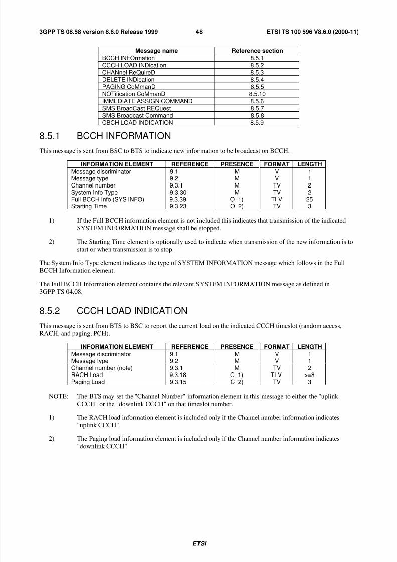
7/27/2019 A-Bis Interface Layer3
http://slidepdf.com/reader/full/a-bis-interface-layer3 49/83
ETSI
ETSI TS 100 596 V8.6.0 (2000-11)483GPP TS 08.58 version 8.6.0 Release 1999
Message name Reference section
BCCH INFOrmation 8.5.1
CCCH LOAD INDication 8.5.2CHANnel ReQuireD 8.5.3DELETE INDication 8.5.4PAGING CoMmanD 8.5.5NOTification CoMmanD 8.5.10
IMMEDIATE ASSIGN COMMAND 8.5.6SMS BroadCast REQuest 8.5.7SMS Broadcast Command 8.5.8CBCH LOAD INDICATION 8.5.9
8.5.1 BCCH INFORMATION
This message is sent from BSC to BTS to indicate new information to be broadcast on BCCH.
INFORMATION ELEMENT REFERENCE PRESENCE FORMAT LENGTH
Message discriminator 9.1 M V 1Message type 9.2 M V 1Channel number 9.3.1 M TV 2System Info Type 9.3.30 M TV 2Full BCCH Info (SYS INFO) 9.3.39 O 1) TLV 25Starting Time 9.3.23 O 2) TV 3
1) If the Full BCCH information element is not included this indicates that transmission of the indicated
SYSTEM INFORMATION message shall be stopped.
2) The Starting Time element is optionally used to indicate when transmission of the new information is to
start or when transmission is to stop.
The System Info Type element indicates the type of SYSTEM INFORMATION message which follows in the Full
BCCH Information element.
The Full BCCH Information element contains the relevant SYSTEM INFORMATION message as defined in
3GPP TS 04.08.
8.5.2 CCCH LOAD INDICATION
This message is sent from BTS to BSC to report the current load on the indicated CCCH timeslot (random access,
RACH, and paging, PCH).
INFORMATION ELEMENT REFERENCE PRESENCE FORMAT LENGTH
Message discriminator 9.1 M V 1Message type 9.2 M V 1Channel number (note) 9.3.1 M TV 2RACH Load 9.3.18 C 1) TLV >=8Paging Load 9.3.15 C 2) TV 3
NOTE: The BTS may set the "Channel Number" information element in this message to either the "uplink CCCH" or the "downlink CCCH" on that timeslot number.
1) The RACH load information element is included only if the Channel number information indicates
"uplink CCCH".
2) The Paging load information element is included only if the Channel number information indicates
"downlink CCCH".

7/27/2019 A-Bis Interface Layer3
http://slidepdf.com/reader/full/a-bis-interface-layer3 50/83
ETSI
ETSI TS 100 596 V8.6.0 (2000-11)493GPP TS 08.58 version 8.6.0 Release 1999
8.5.3 CHANNEL REQUIRED
This message is sent from BTS to BSC to indicate the reception of a CHANnel REQuest message (special access burst
message) from an MS.
INFORMATION ELEMENT REFERENCE PRESENCE FORMAT LENGTH
Message discriminator 9.1 M V 1Message type 9.2 M V 1Channel number 9.3.1 M TV 2Request Reference 9.3.19 M TV 4Access Delay 9.3.17 M TV 2Physical Context 9.3.16 O 1) TLV >=2
1) Optional element for additional physical channel information.
The Request Reference element contains the random access reference value sent by MS in the CHANnel REQuest
message and some low order bits of the absolute frame number for the reception of the access burst.
8.5.4 DELETE INDICATION
This message is sent from BTS to BSC to indicate the deletion of an access grant message (IMMediate ASSIGN) due to
overload of downlink CCCH.
INFORMATION ELEMENT REFERENCE PRESENCE FORMAT LENGTH
Message discriminator 9.1 M V 1Message type 9.2 M V 1Channel number 9.3.1 M TV 2Full Imm. Assign Info 9.3.35 M TLV 25
8.5.5 PAGING COMMAND
This message is sent from BSC to BTS to request the paging of an MS.
INFORMATION ELEMENT REFERENCE PRESENCE FORMAT LENGTH
Message discriminator 9.1 M V 1Message type 9.2 M V 1Channel number 9.3.1 M TV 2Paging Group 9.3.14 M TV 2MS Identity 9.3.12 M TLV 2-10Channel Needed 9.3.40 O 1) TV 2eMLPP Priority 9.3.49 O 2) TV 3
1) If the Channel Needed element is not present, the default value is assumed to be 00 (any channel).
2) If the eMLPP Priority is not present then the BTS does not include the eMLPP priority in the radiointerface message.
The Paging Group element is used by BTS to calculate the correct DRX paging block to be used for the transmission of
the PAGing REQuest message as defined in 3GPP TS 05.02.
8.5.6 IMMEDIATE ASSIGN COMMAND
This message is sent from BSC to BTS to request the transmission of an immediate assignment message.
INFORMATION ELEMENT REFERENCE PRESENCE FORMAT LENGTH
Message discriminator 9.1 M V 1Message type 9.2 M V 1Channel number 9.3.1 M TV 2Full Imm. Assign Info 9.3.35 M TLV 25
The Full Imm. Assign Info element contains the relevant immediate assignment message as defined in 3GPP TS 04.08
(IMMEDIATE ASSIGNMENT or IMMEDIATE ASSIGNMENT EXTENDED or IMMEDIATE ASSIGNMENT
REJECT) with the "Page Mode" element set to the value "no change".

7/27/2019 A-Bis Interface Layer3
http://slidepdf.com/reader/full/a-bis-interface-layer3 51/83
ETSI
ETSI TS 100 596 V8.6.0 (2000-11)503GPP TS 08.58 version 8.6.0 Release 1999
8.5.7 SMS BROADCAST REQUEST
This message is sent from BSC to BTS to request the sending of a Short Message Service Cell Broadcast message.
INFORMATION ELEMENT REFERENCE PRESENCE FORMAT LENGTH
Message discriminator 9.1 M V 1
Message type 9.2 M V 1Channel number 9.3.1 M TV 2SMSCB Information 9.3.36 M TV 24SMSCB Channel Indicator 9.3.44 O 1) TV 2
The SMSCB Information element contains the complete information to be broadcast on the CBCH as defined in
3GPP TS 04.12 (including the Layer 2 header to be used on the radio path).
1) The SMSCB Channel Indicator IE indicates the CBCH which shall be used for broadcasting the data. If
this information element is not present the basic CBCH (see 3GPP TS 05.02) shall be used.
8.5.8 SMS BROADCAST COMMAND
This message is sent from BSC to BTS to command Short Message Service Cell Broadcast.
INFORMATION ELEMENT REFERENCE PRESENCE FORMAT LENGTH
Message discriminator 9.1 M V 1Message type 9.2 M V 1Channel number 9.3.1 M TV 2CB Command type 9.3.41 M TV 2SMSCB message 9.3.42 M TLV 2-90SMSCB Channel Indicator 9.3.44 O 1) TV 2
The CB Command type IE contains the command to be performed, allowing the BSC to:
- request immediate broadcast i.e. transmission in the next CBCH opportunity;
- set the BTS broadcast default mode.
The SMSCB message IE contains the actual message to be broadcast on the CBCH i.e. a maximum of 88 octets of data.
The BTS is responsible for performing the segmentation, building the block types and padding if necessary, see
3GPP TS 04.12 for the message format on the radio path.
1) The SMSCB Channel Indicator IE indicates the CBCH which shall be used for broadcasting the data.
If this information element is not present the basic CBCH [see 3GPP TS 05.02] shall be used.
8.5.9 CBCH LOAD INDICATION
This message is sent from BTS to BSC to indicate a CBCH underflow/overflow situation in the BTS and to request the
BSC to accelerate or pause the cell broadcast for a period indicated by BTS.
INFORMATION ELEMENT REFERENCE PRESENCE FORMAT LENGTH
Message discriminator 9.1 M V 1Message type 9.2 M V 1Channel number 9.3.1 M TV 2CBCH Load Information 9.3.43 M TV 2SMSCB Channel Indicator 9.3.44 O 1) TV 2
The CBCH Load Information element indicates the load situation in CBCH (underflow/overflow) and information
about the requested acceleration/suspension period of cell broadcast.
1) The SMSCB Channel Indicator IE indicates the CBCH which shall be used for broadcasting the data. If this
information element is not present the basic CBCH [see 3GPP TS 05.02] shall be used.

7/27/2019 A-Bis Interface Layer3
http://slidepdf.com/reader/full/a-bis-interface-layer3 52/83
ETSI
ETSI TS 100 596 V8.6.0 (2000-11)513GPP TS 08.58 version 8.6.0 Release 1999
8.5.10 NOTIFICATION COMMAND
This message is sent from BSC to BTS to request a change of notification for voice group call.
INFORMATION ELEMENT REFERENCE PRESENCE FORMAT LENGTH
Message discriminator 9.1 M V 1
Message type 9.2 M V 1Channel number 9.3.1 M TV 2Command indicator 9.3.48 M 1) TLV 3-4Group call reference 9.3.45 O TLV 3-10Channel Description 9.3.46 O TLV 3-nNCH DRX information 9.3.47 O TLV 3
1) This information element indicates the type of command that is to be performed by the BTS with respectto information contained in the rest of the message.
8.6 TRX MANAGEMENT MESSAGES
These messages are related to TRX Management procedures. They all have the following general format (no channel
number included):
INFORMATION ELEMENT REFERENCE PRESENCE FORMAT LENGTH
Message discriminator 9.1 M V 1Message type 9.2 M V 1
(Information elements dependingon message type)
The messages concerned are the following:
Message name Reference section
RF RESource INDication 8.6.1
SACCH FILLing 8.6.2
OVERLOAD 8.6.3
ERROR REPORT 8.6.4
8.6.1 RF RESOURCE INDICATION
This message is sent from BTS to BSC to indicate the interference level on idle channels of a TRX.
INFORMATION ELEMENT REFERENCE PRESENCE FORMAT LENGTH
Message discriminator 9.1 M V 1Message type 9.2 M V 1
Resource Information 9.3.21 M TLV >=2
8.6.2 SACCH FILLING
This message is sent from BSC to BTS to indicate the new broadcast information to be used as filling information on
downlink SACCH.
INFORMATION ELEMENT REFERENCE PRESENCE FORMAT LENGTH
Message discriminator 9.1 M V 1Message type 9.2 M V 1System Info Type 9.3.30 M TV 2L3 Info (SYS INFO) 9.3.11 O 1) TLV 22
Starting Time 9.3.23 O 2) TV 3
1) If the L3 Info information element is not included this indicates that transmission of the indicated
SYSTEM INFORMATION message shall be stopped.

7/27/2019 A-Bis Interface Layer3
http://slidepdf.com/reader/full/a-bis-interface-layer3 53/83
ETSI
ETSI TS 100 596 V8.6.0 (2000-11)523GPP TS 08.58 version 8.6.0 Release 1999
2) The Starting Time element is optionally used to indicate when transmission of the new information is to
start and when transmission is to stop.
The System Info Type element indicates the type of SYSTEM INFORMATION message which follows in the L3 Infofield.
The L3 Information element contains the relevant SYSTEM INFORMATION message as defined in 3GPP TS 04.08.
8.6.3 OVERLOAD
This message is sent from BTS to BSC to indicate an overload situation. Possible cause values include:
- CCCH overload;
- ACCH overload;
- processor overload.
INFORMATION ELEMENT REFERENCE PRESENCE FORMAT LENGTH
Message discriminator 9.1 M V 1
Message type 9.2 M V 1Cause 9.3.26 M TLV >=3
8.6.4 ERROR REPORT
This message is sent from BTS to BSC to report a detected error which cannot be reported in any other message.
INFORMATION ELEMENT REFERENCE PRESENCE FORMAT LENGTH
Message discriminator 9.1 M V 1Message type 9.2 M V 1Cause 9.3.26 M TLV >=3Message Identifier 9.3.28 O 1) TV 2
Channel Number 9.3.1 O 2) TV 2Link identifier 9.3.2 O 3) TV 2Erroneous Message 9.3.38 O 4) TLV >=3
1) Used to indicate which type of message was considered erroneous.
2) Used to indicate for which radio channel the error is reported.
3) Used to indicate for which radio L2 link the error is reported.
4) This element may be used to carry the complete erroneous message as it was received from the BSC.
8.7 LOCATION SERVICES MESSAGES
These messages are related to Location Services (LCS).
8.7.1 LOCATION INFORMATION
This message is sent by the BSC, the BTS or Sandalone Type B LMU via Abis interface to convey an embedded LCS
LLP message.
INFORMATION ELEMENT REFERENCE PRESENCE FORMAT LENGTH
Message discriminator 9.1 M V 1Message type 9.2 M V 1LLP APDU 9.3.58 M LV 2-N

7/27/2019 A-Bis Interface Layer3
http://slidepdf.com/reader/full/a-bis-interface-layer3 54/83
ETSI
ETSI TS 100 596 V8.6.0 (2000-11)533GPP TS 08.58 version 8.6.0 Release 1999
9 Information element codings
This clause contains the codings of the signalling elements used. The following conventions are assumed for the
sequence of transmission of bits and bytes:
- Each bit position is numbered as 1 to 8. 8 7 6 5 4 3 2 1
- The least significant bit is bit 1 and is transmitted first, followed by bits 2, 3, 4 etc.
- In an element, octets are identified by number. Octet 1 is transmitted first, then octet 2 etc.
- When a field extends over more than one octet, the order of bit values progressively decreases as the octet
number increases. The least significant bit of the field is represented by the lowest numbered bit of the highest
numbered octet of the field.
- For variable length elements, a length indicator is included. This indicates the number of octets following in the
element.
- All spare or reserved bits are set to 0.
9.1 Message discriminator
A 1 octet field is used in all messages to discriminate between Transparent and Non-Transparent messages and also
between Radio Link Layer Management, Dedicated Channel Management, Common Channel Management, TRX
Management and Location Services messages.
8 7 6 5 4 3 2 1
G7 G6 G5 G4 G3 G2 G1 T
The T-bit is set to 1 to indicate that the message is to be/was considered transparent by BTS. All other messages shall
have the T-bit set to 0.
The G-bits are used to group the messages as follows:
G7 G6 G5 G4 G3 G2 G1 Message Group
0 0 0 0 0 0 0 reserved
0 0 0 0 0 0 1 Radio Link Layer Management messages
0 0 0 0 1 0 0 Dedicated Channel Management messages
0 0 0 0 1 1 0 Common Channel Management messages
0 0 0 1 0 0 0 TRX Management messages0 0 1 0 0 0 0 Location Services messages
All other values are reserved for future use.
9.2 MESSAGE TYPE
The Message Type uniquely identifies the function of the message being sent. It is a single octet and coded in the
following way:
8 7 6 5 4 3 2 1
EM Message type
Bit 8 is the extension bit and is reserved for future use. The following message types are used (all other values are
reserved):
8 7 6 5 4 3 2 1 Message Reference
0 0 0 0 - - - - Radio Link Layer Management messages:

7/27/2019 A-Bis Interface Layer3
http://slidepdf.com/reader/full/a-bis-interface-layer3 55/83
ETSI
ETSI TS 100 596 V8.6.0 (2000-11)543GPP TS 08.58 version 8.6.0 Release 1999
0 0 0 1 - DATA REQuest 8.3.1
0 0 1 0 - DATA INDication 8.3.2
0 0 1 1 - ERROR INDication 8.3.3
0 1 0 0 - ESTablish REQuest 8.3.4
0 1 0 1 - ESTablish CONFirm 8.3.5
0 1 1 0 - ESTablish INDication 8.3.6
0 1 1 1 - RELease REQuest 8.3.71 0 0 0 - RELease CONFirm 8.3.8
1 0 0 1 - RELease INDication 8.3.9
1 0 1 0 - UNIT DATA REQuest 8.3.10
1 0 1 1 - UNIT DATA INDication 8.3.11
0 0 0 1 - - - - Common Channel Management/TRX Management messages:
0 0 0 1 - BCCH INFOrmation 8.5.1
0 0 1 0 - CCCH LOAD INDication 8.5.2
0 0 1 1 - CHANnel ReQuireD 8.5.30 1 0 0 - DELETE INDication 8.5.4
0 1 0 1 - PAGING CoMmanD 8.5.5
0 1 1 0 - IMMEDIATE ASSIGN COMMAND 8.5.6
0 1 1 1 - SMS BroadCast REQuest 8.5.7
1 0 0 1 - RF RESource INDication 8.6.1
1 0 1 0 - SACCH FILLing 8.6.21 0 1 1 - OVERLOAD 8.6.3
1 1 0 0 - ERROR REPORT 8.6.4
1 1 0 1 - SMS BroadCast CoMmanD 8.5.8
1 1 1 0 - CBCH LOAD INDication 8.5.9
1 1 1 1 - NOTification CoMmanD 8.5.10
0 0 1 - - - - - Dedicated Channel Management messages:
0 0 0 0 1 - CHANnel ACTIVation 8.4.1
0 0 0 1 0 - CHANnel ACTIVation ACKnowledge 8.4.2
0 0 0 1 1 - CHANnel ACTIVation Negative ACK 8.4.30 0 1 0 0 - CONNection FAILure 8.4.4
0 0 1 0 1 - DEACTIVATE SACCH 8.4.50 0 1 1 0 - ENCRyption CoMmanD 8.4.6
0 0 1 1 1 - HANDOver DETection 8.4.7
0 1 0 0 0 - MEASurement RESult 8.4.8
0 1 0 0 1 - MODE MODIFY REQuest 8.4.9
0 1 0 1 0 - MODE MODIFY ACKnowledge 8.4.10
0 1 0 1 1 - MODE MODIFY Negative ACKnowledge 8.4.110 1 1 0 0 - PHYsical CONTEXT REQuest 8.4.12
0 1 1 0 1 - PHYsical CONTEXT CONFirm 8.4.13
0 1 1 1 0 - RF CHANnel RELease 8.4.14
0 1 1 1 1 - MS POWER CONTROL 8.4.15
1 0 0 0 0 - BS POWER CONTROL 8.4.161 0 0 0 1 - PREPROCess CONFIGure 8.4.17
1 0 0 1 0 - PREPROCessed MEASurement RESult 8.4.18
1 0 0 1 1 - RF CHANnel RELease ACKnowledge 8.4.19
1 0 1 0 0 - SACCH INFO MODIFY 8.4.20
1 0 1 0 1 - TALKER DETection 8.4.21
1 0 1 1 0 - LISTENER DETection 8.4.221 0 1 1 1 - REMOTE CODEC CONFiguration REPort 8.4.23
1 1 0 0 0 - Round Trip Delay REPort 8.4.24
1 1 0 0 1 - PRE-HANDOver NOTIFication 8.4.25
1 1 0 1 0 - MultiRate CODEC MODification REQest 8.4.26
1 1 0 1 1 - MultiRate CODEC MOD ACKnowledge 8.4.27
1 1 1 0 0 - MultiRate CODEC MOD Negative ACKnowledge 8.4.28
1 1 1 0 1 - MultiRate CODEC MOD PERformed 8.4.291 1 1 1 0 - TFO REPort 8.4.30
1 1 1 1 1 - TFO MODification REQuest 8.4.31

7/27/2019 A-Bis Interface Layer3
http://slidepdf.com/reader/full/a-bis-interface-layer3 56/83
ETSI
ETSI TS 100 596 V8.6.0 (2000-11)553GPP TS 08.58 version 8.6.0 Release 1999
0 1 - - - - - - Location Services messages:
0 0 0 0 0 1 - Location Information 8.7.1
9.3 Other information elements
The information elements used and the coding of their Element Identifier fields are:Element
Identifier bits
8 7 6 5 4 3 2 1 Element name Reference
0 0 0 0 0 0 0 1 Channel Number 9.3.1
0 0 0 0 0 0 1 0 Link Identifier 9.3.2
0 0 0 0 0 0 1 1 Activation Type 9.3.3
0 0 0 0 0 1 0 0 BS Power 9.3.4
0 0 0 0 0 1 0 1 Channel Identification 9.3.50 0 0 0 0 1 1 0 Channel Mode 9.3.6
0 0 0 0 0 1 1 1 Encryption Information 9.3.7
0 0 0 0 1 0 0 0 Frame Number 9.3.8
0 0 0 0 1 0 0 1 Handover Reference 9.3.90 0 0 0 1 0 1 0 L1 Information 9.3.10
0 0 0 0 1 0 1 1 L3 Information 9.3.110 0 0 0 1 1 0 0 MS Identity 9.3.12
0 0 0 0 1 1 0 1 MS Power 9.3.13
0 0 0 0 1 1 1 0 Paging Group 9.3.14
0 0 0 0 1 1 1 1 Paging Load 9.3.15
0 0 0 1 0 0 0 0 Physical Context 9.3.16
0 0 0 1 0 0 0 1 Access Delay 9.3.17
0 0 0 1 0 0 1 0 RACH Load 9.3.18
0 0 0 1 0 0 1 1 Request Reference 9.3.19
0 0 0 1 0 1 0 0 Release Mode 9.3.20
0 0 0 1 0 1 0 1 Resource Information 9.3.21
0 0 0 1 0 1 1 0 RLM Cause 9.3.220 0 0 1 0 1 1 1 Starting Time 9.3.23
0 0 0 1 1 0 0 0 Timing Advance 9.3.24
0 0 0 1 1 0 0 1 Uplink Measurements 9.3.25
0 0 0 1 1 0 1 0 Cause 9.3.26
0 0 0 1 1 0 1 1 Measurement result number 9.3.27
0 0 0 1 1 1 0 0 Message Identifier 9.3.28
0 0 0 1 1 1 0 1 reserved
0 0 0 1 1 1 1 0 System Info Type 9.3.30
0 0 0 1 1 1 1 1 MS Power Parameters 9.3.31
0 0 1 0 0 0 0 0 BS Power Parameters 9.3.32
0 0 1 0 0 0 0 1 Pre-processing Parameters 9.3.33
0 0 1 0 0 0 1 0 Pre-processed Measurements 9.3.34
0 0 1 0 0 0 1 1 reserved0 0 1 0 0 1 0 0 SMSCB Information 9.3.36
0 0 1 0 0 1 0 1 MS Timing Offset 9.3.37
0 0 1 0 0 1 1 0 Erroneous Message 9.3.38
0 0 1 0 0 1 1 1 Full BCCH Information 9.3.390 0 1 0 1 0 0 0 Channel Needed 9.3.40
0 0 1 0 1 0 0 1 CB Command type 9.3.41
0 0 1 0 1 0 1 0 SMSCB message 9.3.42
0 0 1 0 1 0 1 1 Full Immediate Assign Info 9.3.35
0 0 1 0 1 1 0 0 SACCH Information 9.3.29
0 0 1 0 1 1 0 1 CBCH Load Information 9.3.43
Element
Identifier bits8 7 6 5 4 3 2 1 Element name Reference
0 0 1 0 1 1 1 0 SMSCB Channel Indicator 9.3.44

7/27/2019 A-Bis Interface Layer3
http://slidepdf.com/reader/full/a-bis-interface-layer3 57/83
ETSI
ETSI TS 100 596 V8.6.0 (2000-11)563GPP TS 08.58 version 8.6.0 Release 1999
0 0 1 0 1 1 1 1 Group call reference 9.3.45
0 0 1 1 0 0 0 0 Channel description 9.3.46
0 0 1 1 0 0 0 1 NCH DRX information 9.3.47
0 0 1 1 0 0 1 0 Command indicator 9.3.48
0 0 1 1 0 0 1 1 eMLPP Priority 9.3.49
0 0 1 1 0 1 0 0 UIC 9.3.50
0 0 1 1 0 1 0 1 Main channel reference 9.3.510 0 1 1 0 1 1 0 MultiRate configuration 9.3.52
0 0 1 1 0 1 1 1 MultiRate Control 9.3.53
0 0 1 1 1 0 0 0 Supported Codec Types 9.3.54
0 0 1 1 1 0 0 1 Codec Configuration 9.3.55
0 0 1 1 1 0 1 0 Round Trip Delay 9.3.56
0 0 1 1 1 0 1 1 TFO Status 9.3.57
0 0 1 1 1 1 0 0 LLP APDU 9.3.58
0 0 1 1 1 1 0 1
to
1 1 1 0 1 1 1 1 Reserved for future use
1 1 1 1 0 0 0 0
to1 1 1 1 1 1 1 1 Not used
9.3.1 Channel Number
In the direction BSC to BTS the Channel Number parameter is used to indicate on which physical channel/subchannel
the message is to be sent. In the direction BTS to BSC the Channel Number indicates on which physical
channel/subchannel the message was received. It is coded in two octets as follows:
8 7 6 5 4 3 2 1
Element identifier 1
C5 C4 C3 C2 C1 TN 2
The C-bits describe the channel as follows:
C5 C4 C3 C2 C1
0 0 0 0 1 Bm + ACCH’s0 0 0 1 T Lm + ACCH’s0 0 1 T T SDCCH/4 + ACCH0 1 T T T SDCCH/8 + ACCH1 0 0 0 0 BCCH1 0 0 0 1 Uplink CCCH (RACH)1 0 0 1 0 Downlink CCCH (PCH + AGCH)
The T-bits indicate, coded in binary, the sub-channel number as specified in 3GPP TS 05.02.
TN is time slot number, binary represented as in 3GPP TS 05.02.
9.3.2 Link Identifier
This element identifies the signalling channel and SAPI of the radio data link.
8 7 6 5 4 3 2 1Element identifier 1
C2 C1 NA priority SAPI 2
The NA bit (bit 6 in octet 2) is set to 1 to indicate thet the Link Identifier is not applicable for this message. In all other
cases it is set to 0.
The C-bits indicate the channel type as follows:

7/27/2019 A-Bis Interface Layer3
http://slidepdf.com/reader/full/a-bis-interface-layer3 58/83
ETSI
ETSI TS 100 596 V8.6.0 (2000-11)573GPP TS 08.58 version 8.6.0 Release 1999
C2 C10 0 main signalling channel (FACCH or SDCCH)
0 1 SACCH
All other values are reserved for future use.
The SAPI field contains the SAPI value as defined in 3GPP TS 04.05.
The priority field contains the message priority for SAPI 0, as defined in 3GPP TS 04.06, as follows:
0 0 normal priority
0 1 high priority
1 0 low priority
All other values for SAPI 0 and all values for other SAPIs are reserved for future use.
9.3.3 Activation Type
This element is used to indicate the type of activation requested in the CHANnel ACTIVation message. It is coded in
two octets as follows:
8 7 6 5 4 3 2 1
Element identifier 1
R Reserved A3 A2 A1 2
The R bit indicates if the procedure is an initial activation or a reactivation.
R
0 Initial activation1 Reactivation
The A-bits indicate the type of activation, which defines the access procedure and the operation of the data link layer, asfollows:
A3 A2 A1
0 0 - Activation related to intra-cell channel change
0 - related to immediate assignment procedure
1 - related to normal assignment procedure
0 1 - Activation related to inter-cell channel change (handover)
0 - related to asynchronous handover procedure
1 - related to synchronous handover procedure
1 0 - Activation related to secondary channels0 - related to additional assignment procedure1 - related to multislot configuration
All other values reserved for future use.
NOTE: For the main TCH channel in a Multislot configuration activation types for intra-cell and inter-cell
channel change are used.

7/27/2019 A-Bis Interface Layer3
http://slidepdf.com/reader/full/a-bis-interface-layer3 59/83
ETSI
ETSI TS 100 596 V8.6.0 (2000-11)583GPP TS 08.58 version 8.6.0 Release 1999
9.3.4 BS Power
This information element indicates the TRX transmission power level on a particular channel.
8 7 6 5 4 3 2 1Element identifier 1
Reserved FPC Power Level 2
The FPC (Fast Power Control) field (octet 2) indicates whether Fast Measurement Reporting and Power Control
mechanism is used. It is coded as follows:
Value
0 Fast Power Control not in use
1 Fast Power Control in use
The Power Level field (octet 2) indicates the number of 2 dB steps by which the power shall be reduced from itsnominal value, Pn, set by the network operator to adjust the coverage. Thus the Power Level values correspond to the
following powers (relative to Pn):
Value Power level0 0 0 0 0 Pn
0 0 0 0 1 Pn - 2 dB0 0 0 1 0 Pn - 4 dB..
0 1 1 1 0 Pn - 28 dB0 1 1 1 1 Pn - 30 dBAll other values are reserved for future use.
See also 3GPP TS 05.05, subclause 4.1.2 and 3GPP TS 05.08, subclause 4.5.
9.3.5 Channel Identification
This information element describes some aspects of a channel together with its SACCH.
8 7 6 5 4 3 2 1
Element identifier 1
Length 2
04.08 "Channel Description" *
04.08 "Mobile Allocation" *
A * denotes that the whole of the 04.08 element including the element identifier and length should be included. The
04.08 "Mobile Allocation" shall for compatibility reasons be included but empty, i.e. the length shall be zero.
9.3.6 Channel Mode
This element gives information on the mode of coding/decoding and transcoding/rate adaption of a channel.
8 7 6 5 4 3 2 1Element identifier 1
Length 2
Reserved for future use DTXd DTXu 3Speech or data indicator 4
Channel rate and type 5Speech coding algor./data rate + transp ind 6
The DTX bits of octet 3 indicate whether DTX is applied:

7/27/2019 A-Bis Interface Layer3
http://slidepdf.com/reader/full/a-bis-interface-layer3 60/83
ETSI
ETSI TS 100 596 V8.6.0 (2000-11)593GPP TS 08.58 version 8.6.0 Release 1999
1 DTX is applied
0 DTX is not applied.
DTXd indicates use of DTX in the downlink direction (BTS to MS) and DTXu indicates use of DTX in the uplink direction (MS to BTS).
The "Speech or data indicator" field (octet 4) is coded as follows:
0000 0001 Speech
0000 0010 Data
0000 0011 Signalling
All other values are reserved.
The "Channel rate and type" field (octet 5) is coded as follows:
0000 0001 SDCCH
0000 1000 Full rate TCH channel Bm
0000 1001 Half rate TCH channel Lm
0000 1010 Full rate TCH channel bi-directional Bm, Multislot configuration0001 1010 Full rate TCH channel uni-directional downlink Bm, Multislot configuration
0001 1000 Full rate TCH channel Bm Group call channel
0001 1001 Half rate TCH channel Lm Group call channel
0010 1000 Full rate TCH channel Bm Broadcast call channel
0010 1001 Half rate TCH channel Lm Broadcast call channel
All other values are reserved.
The "speech coding algorithm/data rate + transparency indicator" field (octet 6) is coded as follows:
If octet 4 indicates speech, then octet 6 is coded as follows:
0000 0001 GSM speech coding algorithm version 10001 0001 GSM speech coding algorithm version 2
0010 0001 GSM speech coding algorithm version 3
All other values are reserved.
If octet 4 indicates signalling then octet 6 is coded as follows:
0000 0000 No resources required
All other values are reserved.
NOTE: GSM speech coding algorithm version 3 is also referred as GSM adaptive multirate speech coding
algorithm version 1.
If octet 4 indicates data, then octet 6 is coded as follows:
8 7 6 5 4 3 2 1ext T/NT Rate octet 6
Bit 8: Reserved for extension
Bit 7: 0 Transparent service
1 Non-transparent service.

7/27/2019 A-Bis Interface Layer3
http://slidepdf.com/reader/full/a-bis-interface-layer3 61/83
ETSI
ETSI TS 100 596 V8.6.0 (2000-11)603GPP TS 08.58 version 8.6.0 Release 1999
For the non-transparent service, bits 6 to 1 indicate the radio interface data rate:
65 4321
10 0001 asymmetric 43.5 kbit/s (downlink) + 14.5 kbit/s (uplink)
10 0010 asymmetric 29.0 kbit/s (downlink) + 14.5 kbit/s (uplink)
10 0011 asymmetric 43.5 kbit/s (downlink) + 29.0 kbit/s (uplink)
10 1001 asymmetric 14.5 kbit/s (downlink) + 43.5 kbit/s (uplink)
10 1010 asymmetric 14.5 kbit/s (downlink) + 29.0 kbit/s (uplink)
10 1011 asymmetric 29.0 kbit/s (downlink) + 43.5 kbit/s (uplink)
11 0100 43.5 kbit/s
11 0001 28.8 kbit/s
01 1000 14.5 kbit/s
01 0000 12 kbit/s
01 0001 6 kbit/s
all other values are reserved.
For the transparent service, bits 6-1 indicate the data rate:
65 4321
11 1000 32 kbit/s
11 1001 29 kbit/s
01 1000 14.4 kbit/s
01 0000 9.6 kbit/s
01 0001 4.8 kbit/s
01 0010 2.4 kbit/s
01 0011 1.2 kbit/s
01 0100 600 bit/s
01 0101 1 200/75 bit/s (1 200 network-to-MS, 75 MS-to-network)
All other values are reserved.
9.3.7 Encryption information
This element is a variable length element. It contains necessary information to control encryption devices.
8 7 6 5 4 3 2 1
Element identifier 1Length 2
Algorithm identifier 3
Key 4
n
The Algorithm Identifier field (octet 3) indicates the relevant ciphering algorithm. It is coded as:
0000 0000 Reserved

7/27/2019 A-Bis Interface Layer3
http://slidepdf.com/reader/full/a-bis-interface-layer3 62/83
ETSI
ETSI TS 100 596 V8.6.0 (2000-11)613GPP TS 08.58 version 8.6.0 Release 1999
0000 0001 No encryption shall be used.
0000 0010 GSM encryption algorithm version 1 (A5/1)
0000 0011 GSM A5/2
0000 0100 GSM A5/3
0000 0101 GSM A5/4
0000 0110 GSM A5/5
0000 0111 GSM A5/60000 1000 GSM A5/7
All other values are reserved
The Key field (octets 4-n) indicates the ciphering key. It shall be an integral number of octets and the length is given as
the value of the Length field minus 1.
9.3.8 Frame Number
This element contains the absolute frame number (FN) modulo 42432. It is used to carry the current timing in BTS to
BSC for calculation of the Starting Time parameter required in some messages.
8 7 6 5 4 3 2 1
Element identifier 1T1’ T3 (high) 2
T3 (low) T2 3
Octets 2-3 are coded as defined for octets 2-3 of the Starting Time information element of 3GPP TS 04.08.
9.3.9 Handover reference
The information is coded in two octets and contains the hand-over reference value.
8 7 6 5 4 3 2 1Element identifier 1
Hand RYHUUHIHUHQFH 2
The Handover Reference octet contains the handover reference value as defined in 3GPP TS 04.08.
9.3.10 L1 Information
This element carries the information used in the L1 header of SACCH blocks.
8 7 6 5 4 3 2 1
Element identifier 1MS power level FPC Reserved 2
Actual Timing Advance 3
Octets 2-3 contain the L1 header information of SACCH blocks. The information fields and codings are as defined in
3GPP TS 04.04.
9.3.11 L3 Information (message name)
This element contains a link layer service data unit (L3 message). It is used to forward a complete L3 message as
specified in 3GPP TS 04.08 between BTS and BSC.
8 7 6 5 4 3 2 1Element identifier 1
Length 2
Indicator 3Link Layer Service Data Unit 4
(i.e. a layer 3 message
as defined in 3GPP TS 04.08) n
The Length Indicator field (octets 2-3) indicates in binary the remaining length of the element (octets 4-n). The most
significant bit is bit 8 of octet 2 and the least significant bit is bit 1 of octet 3.

7/27/2019 A-Bis Interface Layer3
http://slidepdf.com/reader/full/a-bis-interface-layer3 63/83
ETSI
ETSI TS 100 596 V8.6.0 (2000-11)623GPP TS 08.58 version 8.6.0 Release 1999
Octets 4-n contain the complete L3 message as defined in 3GPP TS 04.08. In the message format section, the 04.08
message name to be included is indicated within brackets.
9.3.12 MS Identity
This element carries the identity of an MS (TMSI or IMSI). It is a variable length element.
8 7 6 5 4 3 2 1Element identifier 1
Length 2
3MS Identity
N
The MS Identity field (octets 3-N) is coded as specified for the Mobile Identity information element of 3GPP TS 04.08,
octets 3-N.
9.3.13 MS Power
This element carries the power level of MS.
8 7 6 5 4 3 2 1Element identifier 1
Reserved FPC Power Level 2
The FPC (Fast Power Control) field (octet 2) indicates whether Fast Measurement Reporting and Power Control
mechanism is used. It is coded as follows:
Value
0 Fast Power Control not in use
1 Fast Power Control in use
The coding and meaning of the Power Level field is as defined in 3GPP TS 05.05 and 3GPP TS 05.08. See also3GPP TS 04.04.
9.3.14 Paging Group
This element carries the paging population of an MS to be paged.
8 7 6 5 4 3 2 1Element identifier 1
Paging Group 2
The Paging Group field (octet 2) contains the binary representation of the paging group as defined in 3GPP TS 05.02.
9.3.15 Paging Load
This element carries data about the load of a paging channel (PCH).
8 7 6 5 4 3 2 1
Element identifier 12
Paging Buffer Space 3
The Paging Buffer Space field (octets 2-3) indicates the remaining space for Paging Commands associated with this
CCCH timeslot, given as the number of additional Paging Commands that it is possible to store. The number is binary
coded with the most significant bit in bit 8 of octet 2 and the least significant bit in bit 1 of octet 3.

7/27/2019 A-Bis Interface Layer3
http://slidepdf.com/reader/full/a-bis-interface-layer3 64/83
ETSI
ETSI TS 100 596 V8.6.0 (2000-11)633GPP TS 08.58 version 8.6.0 Release 1999
9.3.16 Physical Context
This element contains supplementary information on the transmission/reception process. It is a variable length element.
8 7 6 5 4 3 2 1Element identifier 1
Length 2Physical 3Context
Information N
The Physical Context Information field is not specified. This information should not be analysed by BSC, but merely
forwarded from one TRX/channel to another.
9.3.17 Access Delay
This element contains the delay of the access burst as measured by BTS at random access or at handover access.
8 7 6 5 4 3 2 1
Element identifier 1Access Delay 2
The Access Delay field contains the delay of the access burst as measured by BTS. The delay is expressed as defined
for the Timing Advance TA in 3GPP TS 05.10 but with the range extended to 8 bits, i.e. the six least significant bits of
the field correspond to the Timing Advance except for GSM 400 where all the 8 bits are used.
9.3.18 RACH Load
This element is used to carry information on the load of the RACH (Random Access Channel) associated with this
CCCH timeslot. It is of variable length.
8 7 6 5 4 3 2 1
Element identifier 1Length 23
RACH Slot Count 45
RACH Busy Count 67
RACH Access Count 8
9Supplementary
Information N
The RACH Slot Count field (octets 3-4) indicates the total number of available access slots over which the
measurement (counting) was performed. The value is binary coded with the most significant bit in bit 8 of the first octet
and the least significant bit in bit 1 of the second octet.
The RACH Busy Count field (octets 5-6) indicates the number of RACH burst periods during which the received signal
level has exceeded a given threshold. This will give a measure of the number of "busy" random access slots. The value
is binary coded with the most significant bit in bit 8 of the first octet and the least significant bit in bit 1 of the second
octet.
The RACH Access Count field (octets 7-8) indicates the number of received access bursts during the same
measurement period. The value is binary coded with the most significant bit in bit 8 of the first octet and the least
significant bit in bit 1 of the second octet.
The busy count signal level threshold and the measurement period are parameters set by O&M.
The Supplementary Information field may carry additional operator dependent information.
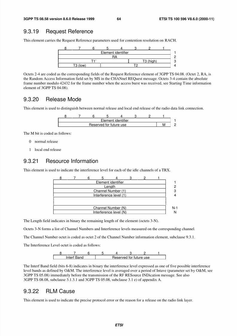
7/27/2019 A-Bis Interface Layer3
http://slidepdf.com/reader/full/a-bis-interface-layer3 65/83
ETSI
ETSI TS 100 596 V8.6.0 (2000-11)643GPP TS 08.58 version 8.6.0 Release 1999
9.3.19 Request Reference
This element carries the Request Reference parameters used for contention resolution on RACH.
8 7 6 5 4 3 2 1Element identifier 1
RA 2T1’ T3 (high) 3T3 (low) T2 4
Octets 2-4 are coded as the corresponding fields of the Request Reference element of 3GPP TS 04.08. (Octet 2, RA, is
the Random Access Information field set by MS in the CHANnel REQuest message. Octets 3-4 contain the absolute
frame number modulo 42432 for the frame number when the access burst was received, see Starting Time information
element of 3GPP TS 04.08).
9.3.20 Release Mode
This element is used to distinguish between normal release and local end release of the radio data link connection.
8 7 6 5 4 3 2 1Element identifier 1Reserved for future use M 2
The M bit is coded as follows:
0 normal release
1 local end release
9.3.21 Resource Information
This element is used to indicate the interference level for each of the idle channels of a TRX.
8 7 6 5 4 3 2 1Element identifier 1
Length 2
Channel Number (1) 3Interference level (1) 4
Channel Number (N) N-1Interference level (N) N
The Length field indicates in binary the remaining length of the element (octets 3-N).
Octets 3-N forms a list of Channel Numbers and Interference levels measured on the corresponding channel.
The Channel Number octet is coded as octet 2 of the Channel Number information element, subclause 9.3.1.
The Interference Level octet is coded as follows:
8 7 6 5 4 3 2 1Interf Band Reserved for future use
The Interf Band field (bits 6-8) indicates in binary the interference level expressed as one of five possible interferencelevel bands as defined by O&M. The interference level is averaged over a period of Intave (parameter set by O&M, see
3GPP TS 05.08) immediately before the transmission of the RF RESource INDication message. See also
3GPP TS 08.08, subclause 3.1.3.1 and 3GPP TS 05.08, subclause 3.1 e) of appendix A.
9.3.22 RLM Cause
This element is used to indicate the precise protocol error or the reason for a release on the radio link layer.

7/27/2019 A-Bis Interface Layer3
http://slidepdf.com/reader/full/a-bis-interface-layer3 66/83
ETSI
ETSI TS 100 596 V8.6.0 (2000-11)653GPP TS 08.58 version 8.6.0 Release 1999
8 7 6 5 4 3 2 1Element identifier 1
Length 2E Cause Value 3
The Cause Value is a one octet field if the extension bit is set to 0. If the extension bit is set to 1, the Cause Value is a
two octet field.
The Cause Value field is coded as follows:
8 7 6 5 4 3 2 1
0 0 0 0 0 0 0 0 reserved
0 0 0 0 0 0 0 1 timer T200 expired (N200+1) times
0 0 0 0 0 0 1 0 re-establishment request
0 0 0 0 0 0 1 1 unsolicited UA response
0 0 0 0 0 1 0 0 unsolicited DM response
0 0 0 0 0 1 0 1 unsolicated DM response, multiple frame established state
0 0 0 0 0 1 1 0 unsolicited supervisory response
0 0 0 0 0 1 1 1 sequence error
0 0 0 0 1 0 0 0 U-frame with incorrect parameters
0 0 0 0 1 0 0 1 S-frame with incorrect parameters
0 0 0 0 1 0 1 0 I-frame with incorrect use of M bit
0 0 0 0 1 0 1 1 I-frame with incorrect length
0 0 0 0 1 1 0 0 frame not implemented
0 0 0 0 1 1 0 1 SABM command, multiple frame established state
0 0 0 0 1 1 1 0 SABM frame with information not allowed in this state
All other values are reserved for future use.
9.3.23 Starting Time
This element provides the starting time expressed as FN modulo 42432 (FN is absolute frame number).
8 7 6 5 4 3 2 1Element identifier 1
T1’ T3 (high) 2T3 (low) T2 3
Octets 2-3 are coded as defined for octets 2-3 of the Starting Time information element of 3GPP TS 04.08.
9.3.24 Timing Advance
This element contains the timing advance to be used by MS in subsequent communications. It is calculated by BTS at
the reception of a CHANnel REQuest message (random access burst) or a handover access burst.
8 7 6 5 4 3 2 1Element identifier 1Timing Advance 2
The Timing Advance field contains the timing advance TA as specified in 3GPP TS 05.10.
Bits 7-8 of octet 2 are used in GSM 400 for support of extended cell range. For all other bands bit 7-8 are spare
according to 04.18.
9.3.25 Uplink Measurements
This element is used to report the results of the TRX measurements on the uplink radio path of an activated basic radio
channel. It is of variable length.

7/27/2019 A-Bis Interface Layer3
http://slidepdf.com/reader/full/a-bis-interface-layer3 67/83
ETSI
ETSI TS 100 596 V8.6.0 (2000-11)663GPP TS 08.58 version 8.6.0 Release 1999
8 7 6 5 4 3 2 1Element identifier 1
Length 2rfu DTXd RXLEV )8// XS 3Reserved RXLEV 68% XS 4
Reserved RXQUAL )8// XS RXQUAL 68% XS 5Supplementary 6
MeasurementInformation N
rfu = Reserved for Future Use.
The Length field indicates in binary the remaining length of the element (octets 3-N).
Octets 3-5 contain results from measurements made by TRX on the uplink.
The Supplementary Measurement Information field (octets 6-N) may carry additional operator dependent information.
The DTXd field (octet 3) indicates whether DTX was employed by TRX on the downlink transmission during the
measurement period.
The RXLEV-FULL-up and RXLEV-SUB-up fields (octets 3-4) report the average uplink signal level as measured byTRX over the measurement period on all slots and on a subset of the slots respectively (see 3GPP TS 05.08, subclause
8.2). Each field is coded as defined in 3GPP TS 05.08, subclause 8.1.4.
The RXQUAL-FULL-up and RXQUAL-SUB-up fields (octet 5) report the average uplink quality as measured by TRX
over the measurement period on all slots and on a subset of the slots respectively (see 3GPP TS 05.08, subclause 8.2).
Each field is coded as defined in 3GPP TS 05.08, subclause 8.2.4.
9.3.26 Cause
The cause element is used to indicate the reason for a particular event to have occurred and is coded as shown below.
8 7 6 5 4 3 2 1
Element identifier 1Length 2
E Cause Value 3Cause Extension 3a
4Diagnostic(s) if any
N
The Length field indicates in binary the remaining length of the element (octets 3-N).
The Cause Value is a single octet field (octet 3) if the extension bit E (bit 8) is set to 0. If it is set to 1 then the cause
value is a 2 octet field (octets 3 and 3a).
The Cause Value is divided into two fields: a class (bits 5-7 of octet 3) and a value within the class (bits 1-4 of octet 3).
If the value of the first octet of the cause field is 1XXX 0000 then the second octet is reserved for national applications(XXX will still indicate the class).
Diagnostic information is not available for every cause, see the table below. When available, it is coded in the same way
as the corresponding information element in clause 9. Inclusion of diagnostics is optional.
Classes:
Class (000): Normal event
Class (001): Normal event
Class (010): Resource unavailable
Class (011): Service or option not available
Class (100): Service or option not implemented

7/27/2019 A-Bis Interface Layer3
http://slidepdf.com/reader/full/a-bis-interface-layer3 68/83
ETSI
ETSI TS 100 596 V8.6.0 (2000-11)673GPP TS 08.58 version 8.6.0 Release 1999
Class (101): Invalid message (e.g. parameter out of range)
Class (110): Protocol error
Class (111): Interworking
CAUSE VALUES:
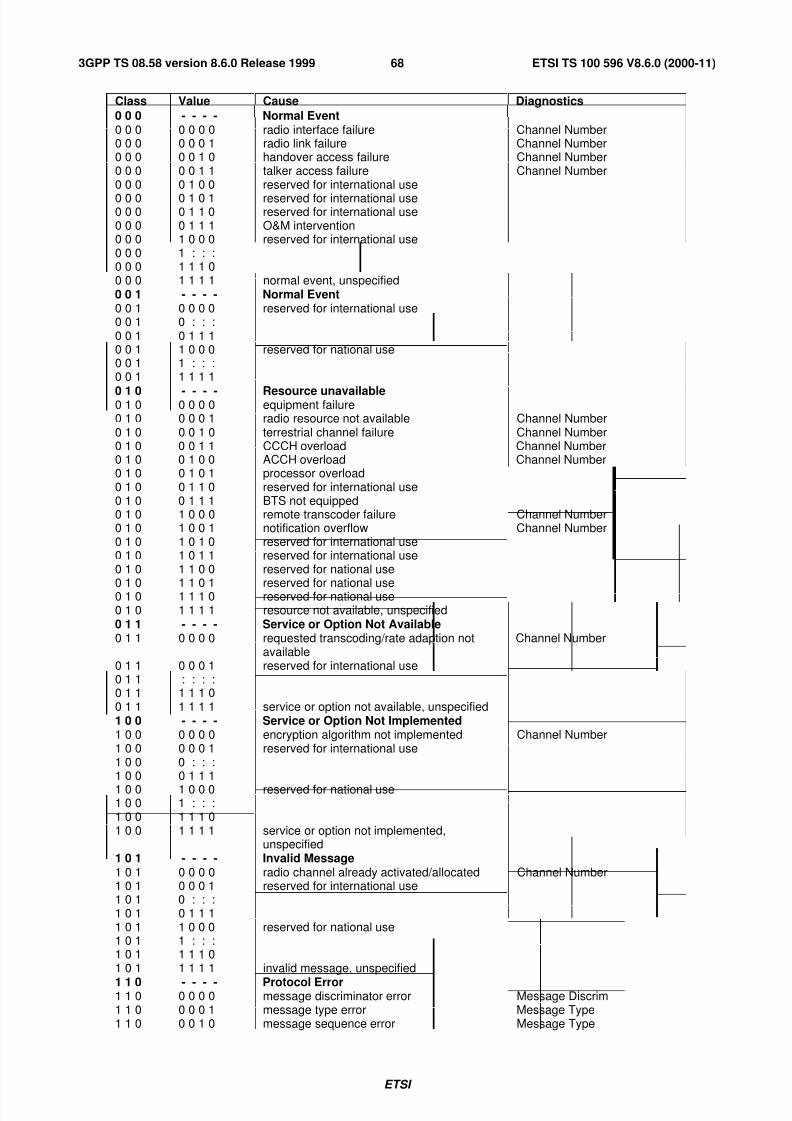
7/27/2019 A-Bis Interface Layer3
http://slidepdf.com/reader/full/a-bis-interface-layer3 69/83
ETSI
ETSI TS 100 596 V8.6.0 (2000-11)683GPP TS 08.58 version 8.6.0 Release 1999
Class Value Cause Diagnostics
0 0 0 - - - - Normal Event0 0 0 0 0 0 0 radio interface failure Channel Number0 0 0 0 0 0 1 radio link failure Channel Number0 0 0 0 0 1 0 handover access failure Channel Number0 0 0 0 0 1 1 talker access failure Channel Number0 0 0 0 1 0 0 reserved for international use
0 0 0 0 1 0 1 reserved for international use0 0 0 0 1 1 0 reserved for international use0 0 0 0 1 1 1 O&M intervention0 0 0 1 0 0 0 reserved for international use0 0 0 1 : : :0 0 0 1 1 1 00 0 0 1 1 1 1 normal event, unspecified0 0 1 - - - - Normal Event0 0 1 0 0 0 0 reserved for international use0 0 1 0 : : :0 0 1 0 1 1 10 0 1 1 0 0 0 reserved for national use0 0 1 1 : : :0 0 1 1 1 1 1
0 1 0 - - - - Resource unavailable0 1 0 0 0 0 0 equipment failure0 1 0 0 0 0 1 radio resource not available Channel Number0 1 0 0 0 1 0 terrestrial channel failure Channel Number0 1 0 0 0 1 1 CCCH overload Channel Number0 1 0 0 1 0 0 ACCH overload Channel Number0 1 0 0 1 0 1 processor overload0 1 0 0 1 1 0 reserved for international use0 1 0 0 1 1 1 BTS not equipped0 1 0 1 0 0 0 remote transcoder failure Channel Number0 1 0 1 0 0 1 notification overflow Channel Number0 1 0 1 0 1 0 reserved for international use0 1 0 1 0 1 1 reserved for international use0 1 0 1 1 0 0 reserved for national use
0 1 0 1 1 0 1 reserved for national use0 1 0 1 1 1 0 reserved for national use0 1 0 1 1 1 1 resource not available, unspecified0 1 1 - - - - Service or Option Not Available0 1 1 0 0 0 0 requested transcoding/rate adaption not
availableChannel Number
0 1 1 0 0 0 1 reserved for international use0 1 1 : : : :0 1 1 1 1 1 00 1 1 1 1 1 1 service or option not available, unspecified1 0 0 - - - - Service or Option Not Implemented1 0 0 0 0 0 0 encryption algorithm not implemented Channel Number1 0 0 0 0 0 1 reserved for international use1 0 0 0 : : :1 0 0 0 1 1 1
1 0 0 1 0 0 0 reserved for national use1 0 0 1 : : :1 0 0 1 1 1 01 0 0 1 1 1 1 service or option not implemented,
unspecified1 0 1 - - - - Invalid Message1 0 1 0 0 0 0 radio channel already activated/allocated Channel Number1 0 1 0 0 0 1 reserved for international use1 0 1 0 : : :1 0 1 0 1 1 11 0 1 1 0 0 0 reserved for national use1 0 1 1 : : :1 0 1 1 1 1 01 0 1 1 1 1 1 invalid message, unspecified
1 1 0 - - - - Protocol Error1 1 0 0 0 0 0 message discriminator error Message Discrim1 1 0 0 0 0 1 message type error Message Type1 1 0 0 0 1 0 message sequence error Message Type

7/27/2019 A-Bis Interface Layer3
http://slidepdf.com/reader/full/a-bis-interface-layer3 70/83
ETSI
ETSI TS 100 596 V8.6.0 (2000-11)693GPP TS 08.58 version 8.6.0 Release 1999
Class Value Cause Diagnostics1 1 0 0 0 1 1 general information element error1 1 0 0 1 0 0 mandatory information element error Element Identif1 1 0 0 1 0 1 optional information element error Element Identif1 1 0 0 1 1 0 information element non-existent Element Identif1 1 0 0 1 1 1 information element length error Element Identif1 1 0 1 0 0 0 invalid information element contents Inform. Element
1 1 0 1 0 0 1 reserved for international use1 1 0 1 0 1 0 reserved for international use1 1 0 1 0 1 1 reserved for international use1 1 0 1 1 0 0 reserved for national use1 1 0 1 1 0 1 reserved for national use1 1 0 1 1 1 0 reserved for national use1 1 0 1 1 1 1 protocol error, unspecified1 1 1 - - - - Interworking1 1 1 0 0 0 0 reserved for international use1 1 1 0 : : :1 1 1 0 1 1 11 1 1 1 0 0 0 reserved for national use1 1 1 1 : : :1 1 1 1 1 1 0
1 1 1 1 1 1 1 interworking, unspecified
9.3.27 Measurement result number
This element is used by BTS to number, (on a channel), the measurement result messages sent to BSC. It is set to 0 at
activation time of the channel. The numbering is modulo 256.
8 7 6 5 4 3 2 1
Element identifier 1Measurement result number 2
9.3.28 Message IdentifierThis element is used to indicate a message type within a message.
8 7 6 5 4 3 2 1Element identifier 1
Message Type 2
Octet 2 is coded as the Message Type information element, subclause 9.2.
9.3.29 SACCH Information
This element is used to carry the SACCH filling information (System Information messages, EXTENDED
MEASUREMENT ORDER message or MEASUREMENT INFORMATION message) that is to be used on a specificchannel. The MEASUREMENT INFORMATION message is periodically sent on SACCH.
8 7 6 5 4 3 2 1Element identifier 1
Length 2
Number of messages 3Type of 1st message 4
Length of 1st message 51st message j
Type of n’th message lLength of n’th message l+1
N
n’th message
The Length field (octet 2) indicates in binary the total remaining length of the element (octets 3 - N).
The Number of SI messages field (octet 3) indicates in binary the number of messages contained in the element.
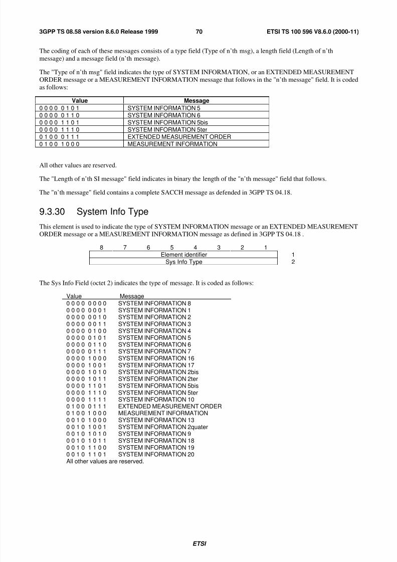
7/27/2019 A-Bis Interface Layer3
http://slidepdf.com/reader/full/a-bis-interface-layer3 71/83
ETSI
ETSI TS 100 596 V8.6.0 (2000-11)703GPP TS 08.58 version 8.6.0 Release 1999
The coding of each of these messages consists of a type field (Type of n’th msg), a length field (Length of n’th
message) and a message field (n’th message).
The "Type of n’th msg" field indicates the type of SYSTEM INFORMATION, or an EXTENDED MEASUREMENTORDER message or a MEASUREMENT INFORMATION message that follows in the "n’th message" field. It is coded
as follows:
Value Message
0 0 0 0 0 1 0 1 SYSTEM INFORMATION 50 0 0 0 0 1 1 0 SYSTEM INFORMATION 60 0 0 0 1 1 0 1 SYSTEM INFORMATION 5bis0 0 0 0 1 1 1 0 SYSTEM INFORMATION 5ter0 1 0 0 0 1 1 1 EXTENDED MEASUREMENT ORDER
0 1 0 0 1 0 0 0 MEASUREMENT INFORMATION
All other values are reserved.
The "Length of n’th SI message" field indicates in binary the length of the "n’th message" field that follows.
The "n’th message" field contains a complete SACCH message as defended in 3GPP TS 04.18.
9.3.30 System Info Type
This element is used to indicate the type of SYSTEM INFORMATION message or an EXTENDED MEASUREMENTORDER message or a MEASUREMENT INFORMATION message as defined in 3GPP TS 04.18 .
8 7 6 5 4 3 2 1Element identifier 1
Sys Info Type 2
The Sys Info Field (octet 2) indicates the type of message. It is coded as follows:
Value Message0 0 0 0 0 0 0 0 SYSTEM INFORMATION 80 0 0 0 0 0 0 1 SYSTEM INFORMATION 10 0 0 0 0 0 1 0 SYSTEM INFORMATION 20 0 0 0 0 0 1 1 SYSTEM INFORMATION 30 0 0 0 0 1 0 0 SYSTEM INFORMATION 40 0 0 0 0 1 0 1 SYSTEM INFORMATION 50 0 0 0 0 1 1 0 SYSTEM INFORMATION 60 0 0 0 0 1 1 1 SYSTEM INFORMATION 70 0 0 0 1 0 0 0 SYSTEM INFORMATION 160 0 0 0 1 0 0 1 SYSTEM INFORMATION 170 0 0 0 1 0 1 0 SYSTEM INFORMATION 2bis0 0 0 0 1 0 1 1 SYSTEM INFORMATION 2ter0 0 0 0 1 1 0 1 SYSTEM INFORMATION 5bis
0 0 0 0 1 1 1 0 SYSTEM INFORMATION 5ter0 0 0 0 1 1 1 1 SYSTEM INFORMATION 100 1 0 0 0 1 1 1 EXTENDED MEASUREMENT ORDER0 1 0 0 1 0 0 0 MEASUREMENT INFORMATION0 0 1 0 1 0 0 0 SYSTEM INFORMATION 130 0 1 0 1 0 0 1 SYSTEM INFORMATION 2quater0 0 1 0 1 0 1 0 SYSTEM INFORMATION 90 0 1 0 1 0 1 1 SYSTEM INFORMATION 180 0 1 0 1 1 0 0 SYSTEM INFORMATION 190 0 1 0 1 1 0 1 SYSTEM INFORMATION 20All other values are reserved.

7/27/2019 A-Bis Interface Layer3
http://slidepdf.com/reader/full/a-bis-interface-layer3 72/83
ETSI
ETSI TS 100 596 V8.6.0 (2000-11)713GPP TS 08.58 version 8.6.0 Release 1999
9.3.31 MS Power Parameters
This element carries the parameters required by TRX for MS power control.
8 7 6 5 4 3 2 1Element identifier 1
Length 2
MS Power Control3
ParametersN
The MS Power Control Parameters field contains the parameters and limits required when MS power control is to be
performed by BTS. The coding is operator dependant. Examples of possible parameters and algorithms can be found in
3GPP TS 05.08 (RXLEV, RX-QUAL-FULL, RX-QUAL-SUB, DISTANCE (Timing Advance) etc.).
9.3.32 BS Power Parameters
This element carries the parameters required by TRX for control of its own transmission power.
8 7 6 5 4 3 2 1
Element identifier 1Length 2
BS Power Control3
ParametersN
The BS Power Control Parameters field contains the parameters and limits required when TRX transmission power
control is to be performed by BTS. The coding is operator dependant. Examples of possible parameters and algorithms
can be found in 3GPP TS 05.08 (RXLEV, RX-QUAL-FULL, RX-QUAL-SUB, DISTANCE (Timing Advance) etc.).
9.3.33 Pre-processing ParametersThis element contains the parameters required by BTS for the pre-processing of radio measurement data.
8 7 6 5 4 3 2 1Element identifier 1
Length 2
reserved for future use P 3
Pre-processing4
ParametersN
The P bit (bit 1 of octet 3) indicates whether pre-processing is to be used and it is coded as follows:
0 use the basic measurement reporting procedure (report raw data);
1 use the pre-processed measurement reporting procedure.
If pre-processing is to be used, the Pre-processing Parameters field (octets 4-N) contains the parameters required byBTS. The coding of this field is operator dependant.

7/27/2019 A-Bis Interface Layer3
http://slidepdf.com/reader/full/a-bis-interface-layer3 73/83
ETSI
ETSI TS 100 596 V8.6.0 (2000-11)723GPP TS 08.58 version 8.6.0 Release 1999
9.3.34 Pre-processed Measurements
This element is used by BTS to report the results of the pre-processing of radio measurement data.
8 7 6 5 4 3 2 1Element identifier 1
Length 2
Pre-processed3
MeasurementsN
The Pre-processed Measurements field (octets 3-N) contains the results of the pre-processing in BTS. The coding of this
field is operator dependant.
9.3.35 Full Immediate Assign Info
This element is used to convey a full L3 immediate assign message (3 types).
8 7 6 5 4 3 2 1Element identifier 1Length Indicator 2
Full Immediate3
Assign Info
25
The Length Indicator field (octet 2) indicates in binary the remaining length of the element (octets 3-25).
The Full Immediate Assign Info field (octets 3-25) contains a complete immediate assign message (IMMEDIATE
ASSIGN or IMMEDIATE ASSIGN EXTENDED or IMMEDIATE ASSIGN REJECT) as defined in 3GPP TS 04.08.
9.3.36 SMSCB InformationThis element is used to convey a complete frame to be broadcast on the CBCH including the Layer 2 header for the
radio path.
8 7 6 5 4 3 2 1Element identifier 1
SMSCB frame 2
24
9.3.37 MS Timing Offset
The information is coded in two octets and contains the MS Timing Offset as measured by the BTS.
8 7 6 5 4 3 2 1Element identifier 1
Timing Offset 2
The meaning of the MS Timing Offset is as defined in 3GPP TS 05.10. The value of MS Timing Offset is the binaryvalue of the 8-bit Timing Offset field (octet 2) - 63. The range of MS Timing Offset is therefore -63 to 192.
9.3.38 Erroneous Message
This information element is used to carry a complete A-bis interface message which was considered erroneous at
reception.

7/27/2019 A-Bis Interface Layer3
http://slidepdf.com/reader/full/a-bis-interface-layer3 74/83
ETSI
ETSI TS 100 596 V8.6.0 (2000-11)733GPP TS 08.58 version 8.6.0 Release 1999
8 7 6 5 4 3 2 1Element identifier 1
Length 2Received Message 3
N
The Received Message field contains a complete A-bis interface L3 message as defined in clause 8 of this GTS,
including Message Discriminator and Message Type.
9.3.39 Full BCCH Information (message name)
This information element contains a complete L3 message as specified in 3GPP TS 04.08.
8 7 6 5 4 3 2 1Element identifier 1Length Indicator 2Layer 3 message 3
as 4defined
in 3GPP TS 04.08 25
The Length Indicator field (octet 2) indicates in binary the remaining length of the element (octets 3-25). The most
significant bit is bit 8 of octet 2 and the least significant bit is bit 1 of octet 2.
Octets 3-25 contain the complete L3 message as defined in 3GPP TS 04.08. In the message format section, the
3GPP TS 04.08 message name to be included is indicated within brackets.
9.3.40 Channel Needed
This information element is used to indicate to the mobile station which channel will be needed for the transaction
linked to the paging procedure.
8 7 6 5 4 3 2 1Element identifier 1
Reserved for future use Channel 2
The Channel Field (bits 1-2 of octet 2) indicates the further combination of channel which will be needed. It is coded as
follows:
Value Channel Needed.
0 0 Any Channel.
0 1 SDCCH.
1 0 TCH/F (Full rate).
1 1 TCH/F or TCH/H (Dual rate).
9.3.41 CB Command type
This element is used to indicate the type of broadcast requested.
8 7 6 5 4 3 2 1Element identifier 1
Command DefaultBroadcast
0Spare
Last Block 2
The Command Field (bits 5 to 8) indicates the command to be performed. It is coded as follows:

7/27/2019 A-Bis Interface Layer3
http://slidepdf.com/reader/full/a-bis-interface-layer3 75/83
ETSI
ETSI TS 100 596 V8.6.0 (2000-11)743GPP TS 08.58 version 8.6.0 Release 1999
Value Command0 0 0 0 Normal message Broadcast.1 0 0 0 Schedule message Broadcast.1 1 1 0 Default message Broadcast.1 1 1 1 Null message Broadcast.All other values are reserved.
When the Command Field is different from the value 1110 (Default message Broadcast), the BTS uses the SMSCBmessage IE together with the Command Field and the Last Block Field to build the blocks sent on the Radio interface,
as defined by 3GPP TS 04.12. In that case bit 4 is ignored.
When the Command Field takes the value 1110 (Default message Broadcast), the BTS uses the SMSCB message IE
together with the Default Broadcast Field and the Last Block Field to build the blocks sent on the Radio interface, as
defined by 3GPP TS 04.12.
The Default Broadcast Field (bit 4) is coded as follows:
Value Default message to be broadcast
0 Normal message.1 Null message.
The BTS uses the Last Block Field to signal to the MS the last block containing useful information as defined by
3GPP TS 04.12. This Field (bits 1 and 2) is coded as follows:
Value Last Block containing useful information
00 Block 401 Block 110 Block 2
11 Block 3
9.3.42 SMSCB Message
This element is used to convey the message to be broadcast on the CBCH.
8 7 6 5 4 3 2 1Element identifier 1
Length 2SMSCB Message 3
N
9.3.43 CBCH Load Information
This information element is used to indicate to the BSC the load situation of CBCH in the BTS.
8 7 6 5 4 3 2 1Element identifier 1
CBCHLoadType
Spare Message Slot Count 2
The CBCH Load Type field (bit 8 of octet 2) indicates either an underflow or an overflow situation of the CBCH in the
BTS. It is coded as follows:
Value CBCH Load Type
0 Underflow1 Overflow
The Message Slot Count field (bits 1-4 of octet 2) indicates either the amount of SMSCB messages that are needed
immediately by BTS or the amount of delay in message slots that is needed immediately by BTS depending on thevalue of the CBCH Load Type field. It is coded as follows:

7/27/2019 A-Bis Interface Layer3
http://slidepdf.com/reader/full/a-bis-interface-layer3 76/83
ETSI
ETSI TS 100 596 V8.6.0 (2000-11)753GPP TS 08.58 version 8.6.0 Release 1999
CBCH Load Type Message Slot Count
0 indicates the amount of SMSCB messages (1-15) that are needed immediately byBTS.
1 indicates the amount of delay in message slots (1-15) that is needed immediately byBTS.
9.3.44 SMSCB Channel Indicator
This element is used to indicate the CB channel [see 3GPP TS 05.02] to be used for broadcasting the data.
8 7 6 5 4 3 2 1
Element identifier 1
Spare Channel Ind 2
This element is used to indicate the CB channel to be used for broadcasting the data. The Channel Ind field is coded as
follows:
Value Channel Ind
0 0 0 0 Basic CBCH0 0 0 1 Extended CBCH (supporting the extended CBCH by the network or MSs is optional)all other values are reserved.
9.3.45 Group call reference
It is coded as follows:
8 7 6 5 4 3 2 1Element identifier 1
Length 2Descriptive group or broadcast call reference 3-8
The octets 3 to 8 are coded in the same way as the octets 1-6 in the Descriptive group or broadcast call reference
information element as defined in 3GPP TS 04.08.
9.3.46 Channel description
This is a variable length element used to pass a radio interface information element from BSC to BTS.
8 7 6 5 4 3 2 1Element identifier 1
Length 2
Group Channel Description 3-n
Octet j (j = 3, 4, ..., n) is the unchanged octet j-2 of a radio interface Group Channel description information element as
defined in 3GPP TS 04.08, n-2 is equal to the length of the radio interface Group channel description information
element.
9.3.47 NCH DRX information
This is a variable length element used to pass a radio interface information element from BSC to BTS.
8 7 6 5 4 3 2 1Element identifier 1
Length 2NCH DRX information 3
Octet 3 bits 1 and 2 are bits 1 and 2 of the radio interface NLN as defined in 3GPP TS 04.08.
Octet 3 bits 3, 4 and 5 are bits 1, 2 and 3 of the radio interface eMLPP priority as defined in 3GPP TS 04.08.
Octet 3 bit 6 is the NLN status parameter as defined in 3GPP TS 04.08.

7/27/2019 A-Bis Interface Layer3
http://slidepdf.com/reader/full/a-bis-interface-layer3 77/83
ETSI
ETSI TS 100 596 V8.6.0 (2000-11)763GPP TS 08.58 version 8.6.0 Release 1999
Octet 3 bits 7 and 8 are spare and set to zero.
9.3.48 Command indicator
8 7 6 5 4 3 2 1Element identifier 1
Length 2E Command Value 3
Command Extension 3a
The Command Value is a single octet field (octet 3) if the extension bit E (bit 8) is set to 0. If it is set to 1 then the
Command value is a 2 octet field (octets 3 and 3a).
COMMAND VALUES:
Value Command
0 0 0 0 0 0 0 Start0 0 0 0 0 0 1 Stop0 0 0 0 0 1 0 reserved for international use0 : : : : : :
1 0 0 0 0 0 0
1 0 0 0 0 0 1 reserved for national use1 : : : : : :1 1 1 1 1 1 1
9.3.49 eMLPP Priority
This Information Element contains the eMLPP priority of the call.
It is coded as follows:
8 7 6 5 4 3 2 1Element identifier 1
spare call priority 2
The call priority field (bit 3 to 1 of octet 2) is coded in the same way as the call priority field (bit 3 to 1 of octet 5) in the
Descriptive group or broadcast call reference information element as defined in 3GPP TS 04.08.
9.3.50 UIC
It is coded as follows:
8 7 6 5 4 3 2 1Element identifier 1
Length 2UIC information 3
Octet 3 bits 1 to 6 contain the radio interface octet 2 bits 3 to 8 of the UIC information element as defined in
3GPP TS 04.08.
Octet 3 bits 7 and 8 are spare and set to zero.
9.3.51 Main channel reference
This element contains the main channel reference of a multislot connection.
It is coded in two octets as follows:

7/27/2019 A-Bis Interface Layer3
http://slidepdf.com/reader/full/a-bis-interface-layer3 78/83
ETSI
ETSI TS 100 596 V8.6.0 (2000-11)773GPP TS 08.58 version 8.6.0 Release 1999
8 7 6 5 4 3 2 1Element identifier 1
Reserved for future use TN 2
TN is time slot number, binary represented as in 3GPP TS 05.02.
9.3.52 MultiRate configurationThis element gives the description of the multirate speech codec configuration to be applied.
8 7 6 5 4 3 2 1
Element identifier 1Length 2
Rest of element coded as in 3GPP TS 04.08 not including3GPP TS 04.08 element identifier or 3GPP TS 04.08 octet length
value
3-n
9.3.53 MultiRate Control
This element indicates whether TFO is enabled or not and whether the BSC authorises the BTS to performautonomously multi-rate codec changes and whether an handover is to be expected.
It is coded in two octets as follows:
8 7 6 5 4 3 2 1Element identifier 1
Spare PRE RAE TFO 3
The TFO field (bit 1 of octet 3) indicates if TFO is enabled or not. It is coded as follows:
Value TFO
0 Tandem Free Operation is enabled
1 Tandem Free Operation is disabled
The RAE field (bits 2-3, octet 3) defines whether the RATSCCH mechanism is enabled or not. It is coded as follows:
Value RAE
0 0 RATSCCH mechanism is generally enabled, the BTS may change the AMR configuration within
the given SCS and MACS constraints and within the given radio and Abis channel.
0 1 RATSCCH mechanism will potentially be enabled for one exchange. The BSC will use a
MultiRate CODEC MOD REQ message for that purpose
1 0 reserved
1 1 RATSCCH mechanism is generally disabled
The PRE field (bit 4 of octet 3) indicates if an handover is to be expected soon or not. It is coded as follows:
Value PRE
0 Handover is not expected, respectively has failed
1 Handover is expected soon
9.3.54 Supported Codec Types
This element indicates the codec types supported by the BSS or remote BSS.
It is coded as follows:

7/27/2019 A-Bis Interface Layer3
http://slidepdf.com/reader/full/a-bis-interface-layer3 79/83
ETSI
ETSI TS 100 596 V8.6.0 (2000-11)783GPP TS 08.58 version 8.6.0 Release 1999
8 7 6 5 4 3 2 1Element identifier 1
Length 2Sys-ID 3
ext Codec List 4-n
Preferred Codec Type n+1
The Sys-ID field (octet 3) identifies the system that sends or has sent the configuration. It should be set to 0000 0000 for
GSM.
The Codec List field (octet 4) lists the codec types that are supported by the BSS and Transcoder, and are therefore
potential candidates for TFO establishment. If the Preferred Codec Type is not present (this field is set to “1111.1111”),
then the Codec List belongs to the remote BSS, otherwise it is the list of alternative Preferred Codec Types. It is coded
as follows:
Bit 1: Set to 1 if the GSM FR Speech Codec is supported.
Bit 2: Set to 1 if the GSM HR Speech Codec is supported.
Bit 3: Set to 1 if the GSM EFR Speech Codec is supported.
Bit 4: Set to 1 if the GSM FR AMR Speech Codec is supported.
Bit 5: Set to 1 if the GSM HR AMR Speech Codec is supported
Bit 6-7: Reserved, set to 0.Bit 8: Reserved for extension, set to 0.
If bit 4 of the Codec List field (octet 4) indicates that FR AMR is supported or if bit 5 of the Codec List field (octet 4)
indicates that HR AMR is supported, the following two octets (octets 5-6) should be coded as follows:
8 7 6 5 4 3 2 1Spare TFO_VER MACS 5
SCS 6
If both FR AMR and HR AMR are supported, the octets 5-6 shall be sent twice. The first occurrence shall correspond to
FR AMR configuration, the second one shall correspond to HR AMR configuration.
The MACS field (bits 1-2 of octet 5, if present) indicates the Maximum number of AMR Codec ModeS the BSS can
support in the Active Codec Set. It should be coded as follows:
0 0: A maximum of four codec modes can be supported in the Active Codec Set
0.1: A maximum of one codec mode can be supported in the Active Codec Set
1.0: A maximum of two codec modes can be supported in the Active Codec Set
1.1: A maximum of three codec modes can be supported in the Active Codec Set
The TFO_VER field (bits 3-4 of octet 5, if present) indicates the TFO_VERSION.
0 0 : Version 0 of TFO
All other values reserved for future used
The SCS field (octet 6 if present) indicates the Set of AMR Codec modes Supported by the BSS. It should be coded as
follows:
Bit 8: Set to 1 if the AMR 12.2 Codec Mode is supported.
Bit 7: Set to 1 if the AMR 10.2 Codec Mode is supported.
Bit 6: Set to 1 if the AMR 7.95 Codec Mode is supported.
Bit 5: Set to 1 if the AMR 7.40 Codec Mode is supported.
Bit 4: Set to 1 if the AMR 6.70 Codec Mode is supported.Bit 3: Set to 1 if the AMR 5.90 Codec Mode is supported.
Bit 2: Set to 1 if the AMR 5.15 Codec Mode is supported.
Bit 1: Set to 1 if the AMR 4.75 Codec Mode is supported.

7/27/2019 A-Bis Interface Layer3
http://slidepdf.com/reader/full/a-bis-interface-layer3 80/83
ETSI
ETSI TS 100 596 V8.6.0 (2000-11)793GPP TS 08.58 version 8.6.0 Release 1999
The Preferred Codec Field (bits 1-8, octet n+1) indicates the preferred codec type for TFO establishment. It is coded as
follows;
0 0 0 0 . 0 0 0 0: Full Rate Codec is preferred
0 0 0 0 . 0.0 0 1: Half Rate Codec is preferred
0 0 0 0 . 0 0 1.0: Enhanced Full Rate Codec is preferred0 0 0 0 . 0 0 1.1: FR Adaptive Multi-Rate Codec is preferred
0 0 0 0 . 0 1 0 0: HR Adaptive Multi-Rate Codec is preferred
1 1 1 1 . 1 1 1 1: No preferred codec type
All other values reserved for future used
9.3.55 Codec Configuration
This element indicates the active codec in the BSS or the remote BSS
It is coded as follows:
8 7 6 5 4 3 2 1Element identifier 1
Length 2Active Codec Type 3
The Active Codec Type field (bits 1-8, octet 3) indicates the type of codec in use. It is coded as follows:
0 0 0 0 . 0 0 0 0: Full Rate Codec in use
0 0 0 0 . 0 0 0 1: Half Rate Codec in use
0 0 0 0 . 0 0 1 0: Enhanced Full Rate Codec in use
0 0 0 0 . 0 0 1 1: FR Adaptive Multi Rate Codec in use
0 0 0 0 . 0 1 0 0: HR Adaptive Multi Rate Codec in use
All other values are reserved for future use
If the Active Codec Type field (octet 3) indicates that AMR (FR or HR) is the active codec type, then the following two
octets (octets 4-5) shall provide the configuration in use. They shall be coded as follows:
8 7 6 5 4 3 2 1
Spare ICM 4Active Codec Set 5
The ICM field (bits 1-2, octet 4) defines the Initial Codec Mode. It is coded as defined in the 3GPP TS 05.09, section
3.4.1.
The Active Codec Set (octet 5) defines the set of AMR codec modes used in the active set. It is coded as defined for the
Set of AMR codec modes in the Multi-Rate configuration IE in the 3GPP TS 04.08, section 10.5.2.21aa.
9.3.56 Round Trip Delay
This element indicates the value of the calculated round trip delay between the BTS and the transcoder, or between the
BTS and the remote BTS, if TFO is established.
It is coded in 2 octets as follows:
8 7 6 5 4 3 2 1Element identifier 1
RTD DelayIND
2
The RTD field is the binary representation of the value of the round trip delay in 20 ms increments.

7/27/2019 A-Bis Interface Layer3
http://slidepdf.com/reader/full/a-bis-interface-layer3 81/83
ETSI
ETSI TS 100 596 V8.6.0 (2000-11)803GPP TS 08.58 version 8.6.0 Release 1999
The Delay IND field indicates if the delay corresponds to a BTS to transcoder delay or to a BTS to remote BTS delay. It
is coded as follows:
Value Delay IND
0 The RTD field contains the BTS-Transcoder round trip delay
1 The RTD field contains the BTS-Remote BTS round trip delay
9.3.57 TFO Status
This element indicates if TFO is established. It is coded in 2 octets as follows :
8 7 6 5 4 3 2 1Element identifier 1Spare TFO 2
The TFO field shall be coded as follows :
Value TFO
0 TFO is not established
1 TFO is established
9.3.58 LLP APDU
This is a variable length element that conveys an embedded message or message segment associated with the higher
level protocol LLP, as defined in 3GPP TS 04.71. This element can be sent from the BSC to the BTS or to the
Standalone Type B LMU, and vice versa.
8 7 6 5 4 3 2 1
Element identifier 1
Length 2The rest of the information element contains the embeddedmessage that contains a Facility Information Element as defined in3GPP TS 04.71 excluding the Facility IEI and length of Facility IEI
octets defined in 3GPP TS 04.71.
3-n

7/27/2019 A-Bis Interface Layer3
http://slidepdf.com/reader/full/a-bis-interface-layer3 82/83
ETSI
ETSI TS 100 596 V8.6.0 (2000-11)813GPP TS 08.58 version 8.6.0 Release 1999
Annex A (informative):Change history
SMG# CR Rev Subject New VersS29 A035 Modifications to Channel Mode IE due to EDGE 8.0.2
S30 A036 1 ECSD Asymmetry 8.1.0
S30 A037 1 Modification due to Fast Power Control for ECSD 8.1.0
S30 A043 L3 Info IE length in SACCH INFO MODIFY and FILLING 8.1.0
S30 A045 Introduction of the AMR SMG2 TRAU/SMG11 TFO 8.1.0
S30bis A046 2 Support of extended timing advance information element in08.58
8.2.0
S30bis A049 TFO AMR 8.2.0
S30bis A051 Access delay info element clarification for GSM400 8.2.0
S31 A050 3 Addition of LCS message 8.3.0
- - - Editorial correction to Change History and graphics update forfont compatibility
8.3.1
s31bis A052 Enhanced measurement reporting capability 8.4.0
GP-01 A054 Correction to Channel Mode IE 8.5.0- - - FPC in figure on BS Power IE re-introduced 8.5.0
GP-02 A056 2G-3G cell reselection and HO, EGPRS 8.6.0
- - - Many table formats corrected. Headers corrected 8.6.0

7/27/2019 A-Bis Interface Layer3
http://slidepdf.com/reader/full/a-bis-interface-layer3 83/83
82 ETSI TS 100 596 V8.6.0 (2000-11)3GPP TS 08.58 version 8.6.0 Release 1999
History
Document history
V8.3.1 May 2000 Publication
V8.4.0 October 2000 Publication
V8.5.0 October 2000 Publication
V8.6.0 November 2000 Publication
Related Documents