Place Graphic Here One of the major issues that prevent a large- scale dissemination of drip irrigation system is the requirement of high pumping pressure, which incurs a high cost of pumping and power systems. The high pressure is used to maintain the working condition of pressure-compensate emitters, which are installed at the outlets of drip irrigation system to compensate pressure loss and evenly distribute flows for each crop. Abstract Introduction Methodology Results A Bio-inspired Pressure Compensating Emitter for Low-Cost Drip Irrigation Systems Ruo-Qian Wang, Amos G Winter V Dept. of Mechanical Engineering, MIT ©Copyright, All Rights Reserved Contact: [email protected] Place Graphic Here Background Because of climate change, population growth, urbanization, and water pollution, the world is facing a water and food crisis. For example, the projected annual water usage of India for 2025 is 1020 km 3 , among which agriculture use contributes to 73% [1]. Drip irrigation is a potential solution • Save 30-70% water use compared to flood irrigation • Increase crop yields by 23-98% • Allow high-value crops to grow [2] High cost prevents large-scale applications • only 5% adoption of drip irrigation • high cost of ~$3000/acre with solar power • 90% of cost is power and pumping systems [2] A technological breakthrough is needed • Pumping power = pressure x flow rate • Current pressure demand is 3.5 bar [2] • Pressure compensating emitter (figure 1 & 5) needs ~1 bar [2] A bio-inspired design -30 -25 -20 -15 -10 -5 5 0 -5 -10 -15 -20 -25 -30 0.5 1 A / A0 Kp ∆P e) A new architecture of the pressure-compensate emitter is proposed using a flexible tube enclosed in a pressurized chamber similar to the design of a medical instrument called “Starling resistor”. This design enables the external pressure of the tube to correlate with the driving pressure, such that a higher driving pressure leads to a higher external pressure and consequently collapses the tube. The desirable feature that the flow rate is independent of the upstream pressure variation can be achieved with this new design at a lower driving pressure. This project is aimed to find the optimal combination of the design parameters that govern the physics behind the collapsible tube. A laboratory experiment has been conducted using rubber tubes with a variety of lengths, wall thicknesses and inner diameters. Then, an attempt to collapse the experimental results are made and empirical formula of activation pressure and regulated flow rate are given. Experiment Setup References [1] FAO. "Agriculture, food and water." (2003). [2] Information provided by Jain Irrigation Ltd. [3] Zimoch, et al. ”Bio-inspired, low-cost, self- regulating valves for drip irrigation in developing countries." IDETC (2013). Acknowledgement The authors would like to thank Jain Irrigation Inc. and MIT Tata Center for Research and Design for their support throughout the project. We are exploring a new drip emitter architecture consisting of an enclosed collapsible tube for pressure compensation. This novel architecture is based on a “Starling Resistor” – a means of restricting fluid flow by applying an external pressure to a flexible tube. Starling resistors are commonly found throughout the human body. An example is the bronchi in the lungs, which collapse and make a person wheeze when they exhale hard (see figure 4). [3] www.sultansurgicalcenter.com A series of experiments has been conducted to investigate the pressure compensation of collapsible tubes inside a pressurized chamber (figure 6), including four factors: • Tube length (L) • Wall Thickness (h) • Inner Diameter (D) • Materials (E) Pressure compensation • Flow rate increases with pressure before activation pressure • Flow rate is independent of pressure variation after activation pressure • The minimum activation pressure is ~ 0.2 bar (figure 7) Self-excited oscillation • Co-existing with pressure compensating • Potentially anti-clogging Hysteric effect Flow rate is higher in pressure increasing compared to pressure decreasing (arrows in figure 7) Figure 1 Pressure Compensating emitter Figure 2 Water and food crisis in India Figure 3 High pressure is needed in drip irrigation Figure 4 Collapsible tubes in respiratory airways Figure 5 Pressure compensation in commercial emitter Figure 6 Experimental Configuration Figure 7 Experimental results MIT GLOBAL ENGINEERING AND RESEARCH (GEAR) LABORATORY GEAR.MIT.EDU GEAR LAB GEAR LAB GEAR LAB G G G G P (bar)

Welcome message from author
This document is posted to help you gain knowledge. Please leave a comment to let me know what you think about it! Share it to your friends and learn new things together.
Transcript
Place Graphic Here
Place Graphic Here
One of the major issues that prevent a large-scale dissemination of drip irrigation system is the requirement of high pumping pressure, which incurs a high cost of pumping and power systems. The high pressure is used to maintain the working condition of pressure-compensate emitters, which are installed at the outlets of drip irrigation system to compensate pressure loss and evenly distribute flows for each crop.
Abstract Introduction Methodology Results
A Bio-inspired Pressure Compensating Emitter for Low-Cost Drip Irrigation Systems Ruo-Qian Wang, Amos G Winter V
Dept. of Mechanical Engineering, MIT
©Copyright, All Rights Reserved Contact: [email protected]
Place Graphic Here
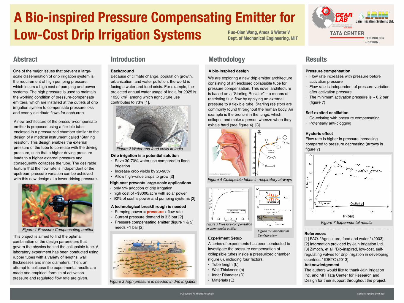
BackgroundBecause of climate change, population growth, urbanization, and water pollution, the world is facing a water and food crisis. For example, the projected annual water usage of India for 2025 is 1020 km3, among which agriculture use contributes to 73% [1].
Drip irrigation is a potential solution• Save 30-70% water use compared to flood
irrigation• Increase crop yields by 23-98%• Allow high-value crops to grow [2]
High cost prevents large-scale applications• only 5% adoption of drip irrigation• high cost of ~$3000/acre with solar power• 90% of cost is power and pumping systems [2]
A technological breakthrough is needed• Pumping power = pressure x flow rate• Current pressure demand is 3.5 bar [2]• Pressure compensating emitter (figure 1 & 5)
needs ~1 bar [2]
A bio-inspired design
0.2 0.4 0.6 0.8 1.0
-30
-25
-20
-15
-10
-5
~ 0.1-0.3 bar 20 40 60
∆P [cm H2O]1
2
3
4
5
Q [liter/sec].
Pin Pout
Pin = Pout
NO FLOW
5
0
-5
-10
-15
-20
-25
-30
0.5 1A / A0
Kp
∆P
b)
d)
a)
c)
Pin PoutQ.
Pin > Pout
PRESSURE COMPENSATION
Pin
compression
e)
PinPout
Pin
h
E
�AA02r
L
D
FIGURE 2. Bio-inspired pressure-compensation. a) Flow rate -pressure relationship in the human airway, as measured by Afschriftet.al. The graphic is partially based on the image available athttp://en.wikipedia.org/wiki/File:Respiratory system complete en.svg(accessed January 5, 2013) [8]. b) Simple model of the human airway:a flexible tube (orange) fixed on two rigid supports (black) and placed ina chamber open to the inlet pressure. To represent all variables used, thevalve is drawn in the pressure-compensating configuration. c) Relaxedconfiguration of the valve. When the inlet and outlet pressures areequal, there is no differential pressure acting across the flexible tube,whose diameter is constant. d) Pressure compensating configuration.When Pin > Pout , a difference in pressure across the flexible tubecauses its collapse and gradual variation in cross sectional area, whichobstructs the flow. e) Tube Law. The variation of cross sectional area ofa flexible cylinder with transmural pressure. Black solid line representsempirical relationship. Orange dashed line represents equation 3 withn = 3/2. The inset shapes represent the cross-sectional area of the tubeat various pressures. . Figure 2e) is based on Fig. 1 in [6].
pressures, the walls of the tube cave in and the response is gov-erned by bending of the tube walls. This asymmetry is shown inFig. 2e. The relationship between cross sectional area and trans-mural pressure in elastic tubes is commonly called the tube law,and is determined experimentally [9]. However, in the interestof simplicity, following Shapiro [6], a dimensionless analyticalexpression can be fitted to the experimental curve, of the form
DPKp
= a�n �1, (3)
where a = A/A0, A0 = pr2, n is an empirical factor between 1and 2, and Kp represents the bending stiffness of the tube’s walls,and is proportional to E(h/r)3. Subtracting 1 ensures there is nopredicted area change for zero transmural pressure.
The system shown in Fig. 2b,c,d is one version of a deviceoften called the Starling Resistor, which is a simplified but veryuseful model of physiological flows in the lungs and blood ves-sels [10].
Combining equations 2 and 3, Shapiro [6] arrived at the fol-lowing relationship,
⇣DPKp
⌘1/2
⇣DPKp
+1⌘1/n = Q
✓K f
2Kp
rA2
0
◆1/2, (4)
which describes the relationship between the applied pressuredifference DP and the flow rate Q̇ through the tube. This ex-pression is plotted in Fig. 3 for n ranging between 1 and 2.In all cases, the pressure-compensating effect is strong beyondDP/Kp ⇡ 2, which marks the activation pressure of the valve.The case for n = 2 and DP � Kp approaches the exact pres-sure compensation as derived in the previous section. This isevident in the asymptotic approach of the curve for n = 2 to
Q̇⇣
K f2Kp
rA2
0
⌘1/2= 1. We note that, following Shapiro [6], we as-
sume that L µ D, that is the friction loss occurs near the exit, overa length proportional to the smallest diameter of the constriction.
PROOF-OF-CONCEPT PROTOTYPETo demonstrate that elastic tube deformation can result in
pressure-compensation in the range of pressures and flow ratesrequired by drip irrigation, we constructed a laboratory-scaleprototype of a PC valve modelled on the human airway. In thissection, we describe our methods and results of testing the pro-totype.
Prototype Design and ConstructionOne benefit of the simple features of the elastic tube PC
valve design is that it can be realized in a variety of ways. In
4 Copyright c� 2013 by ASME
A new architecture of the pressure-compensate emitter is proposed using a flexible tube enclosed in a pressurized chamber similar to the design of a medical instrument called “Starling resistor”. This design enables the external pressure of the tube to correlate with the driving pressure, such that a higher driving pressure leads to a higher external pressure and consequently collapses the tube. The desirable feature that the flow rate is independent of the upstream pressure variation can be achieved with this new design at a lower driving pressure.
This project is aimed to find the optimal combination of the design parameters that govern the physics behind the collapsible tube. A laboratory experiment has been conducted using rubber tubes with a variety of lengths, wall thicknesses and inner diameters. Then, an attempt to collapse the experimental results are made and empirical formula of activation pressure and regulated flow rate are given.
Experiment SetupReferences[1] FAO. "Agriculture, food and water." (2003).[2] Information provided by Jain Irrigation Ltd.[3] Zimoch, et al. ”Bio-inspired, low-cost, self-regulating valves for drip irrigation in developing countries." IDETC (2013).AcknowledgementThe authors would like to thank Jain Irrigation Inc. and MIT Tata Center for Research and Design for their support throughout the project.
We are exploring a new drip emitter architecture consisting of an enclosed collapsible tube for pressure compensation. This novel architecture is based on a “Starling Resistor” – a means of restricting fluid flow by applying an external pressure to a flexible tube. Starling resistors are commonly found throughout the human body. An example is the bronchi in the lungs, which collapse and make a person wheeze when they exhale hard (see figure 4). [3]
www.sultansurgicalcenter.com
A series of experiments has been conducted to investigate the pressure compensation of collapsible tubes inside a pressurized chamber (figure 6), including four factors:• Tube length (L)• Wall Thickness (h)• Inner Diameter (D)• Materials (E)
Pressure compensation• Flow rate increases with pressure before
activation pressure• Flow rate is independent of pressure variation
after activation pressure• The minimum activation pressure is ~ 0.2 bar
(figure 7)
Self-excited oscillation• Co-existing with pressure compensating• Potentially anti-clogging
Hysteric effectFlow rate is higher in pressure increasing compared to pressure decreasing (arrows in figure 7)
Figure 1 Pressure Compensating emitter
Figure 2 Water and food crisis in India
Figure 3 High pressure is needed in drip irrigation
Figure 4 Collapsible tubes in respiratory airways
Figure 5 Pressure compensation in commercial emitter
Figure 6 Experimental Configuration
Figure 7 Experimental results
MIT GLOBAL ENGINEERING AND RESEARCH (GEAR) LABORATORY
GEAR.MIT.EDU
GEARLABGEARLABGEARLABGGGG
P (bar)
Related Documents