A better calculator: Processing hand-written mathematical expressions to solve problems Will Thimbleby May 5, 2004

Welcome message from author
This document is posted to help you gain knowledge. Please leave a comment to let me know what you think about it! Share it to your friends and learn new things together.
Transcript

A better calculator: Processing hand-written
mathematical expressions to solve problems
Will Thimbleby
May 5, 2004
Abstract
Current methods of calculating and entering mathematical expressions ontypical calculators, whether handheld or on screen, are awkward and cum-bersome. Today, computers are capable of almost anything — yet GUIcalculators are still imitations the very earliest electronic models! Usersare being forced to use calculators a unnatural way dictated by obsoletemetaphors. A novel calculator, that provides a natural interface, much likepen and paper is presented. The interface provides a dynamic method ofentering conventional written expressions by normal gestures and providescontinual feedback showing the calculation and results. Furthermore, theuser interface adjusts and copes with partial expressions, morphing the ex-pressions to correct position and syntax. Gestures are also used to editand manipulate calculations. The user interface is declarative, in that alldisplays, even with partial user input, are of correct calculations.
A usability test was designed and conducted to evaluate the effectivenessof the system when compared with current handheld or computer calcula-tors. It was found that the new system presented here was faster for morecomplex expressions and importantly, gave users more confidence in its re-sults. The majority of users said that they would prefer to use this calculatorrather than their existing calculator.
This thesis provides a survey of the relevant literature, a detailed descrip-tion of the algorithms and gesture recognition, and illustrates the calculatorbehaviour with image sequences taken from real use.
Contents
1 Introduction 11.1 The problem . . . . . . . . . . . . . . . . . . . . . . . . . . . 11.2 A solution . . . . . . . . . . . . . . . . . . . . . . . . . . . . . 21.3 Outline . . . . . . . . . . . . . . . . . . . . . . . . . . . . . . 5
2 Existing methods 62.1 Linear Interfaces . . . . . . . . . . . . . . . . . . . . . . . . . 62.2 Template based interfaces . . . . . . . . . . . . . . . . . . . . 72.3 Visual entry . . . . . . . . . . . . . . . . . . . . . . . . . . . . 82.4 Summary . . . . . . . . . . . . . . . . . . . . . . . . . . . . . 10
3 Symbol recognition 113.1 Issues with symbol recognition . . . . . . . . . . . . . . . . . 123.2 Segmentation . . . . . . . . . . . . . . . . . . . . . . . . . . . 133.3 Signal processing . . . . . . . . . . . . . . . . . . . . . . . . . 153.4 Statistical methods . . . . . . . . . . . . . . . . . . . . . . . . 153.5 Structural and syntactic methods . . . . . . . . . . . . . . . . 163.6 Model matching . . . . . . . . . . . . . . . . . . . . . . . . . . 173.7 Summary . . . . . . . . . . . . . . . . . . . . . . . . . . . . . 19
4 Expression recognition 204.1 Issues with expression recognition . . . . . . . . . . . . . . . . 204.2 Top-down versus bottom-up . . . . . . . . . . . . . . . . . . . 244.3 Methods . . . . . . . . . . . . . . . . . . . . . . . . . . . . . . 244.4 Summary . . . . . . . . . . . . . . . . . . . . . . . . . . . . . 30
5 Implementation 315.1 Tools . . . . . . . . . . . . . . . . . . . . . . . . . . . . . . . . 315.2 Symbol recognition . . . . . . . . . . . . . . . . . . . . . . . . 325.3 Expression recognition . . . . . . . . . . . . . . . . . . . . . . 345.4 Summary . . . . . . . . . . . . . . . . . . . . . . . . . . . . . 38
6 Calculation 396.1 Simple calculators . . . . . . . . . . . . . . . . . . . . . . . . 406.2 Useable calculators . . . . . . . . . . . . . . . . . . . . . . . . 406.3 Symbolic calculators . . . . . . . . . . . . . . . . . . . . . . . 406.4 A new design . . . . . . . . . . . . . . . . . . . . . . . . . . . 416.5 Summary . . . . . . . . . . . . . . . . . . . . . . . . . . . . . 43
ii
7 The interface 447.1 User interface design . . . . . . . . . . . . . . . . . . . . . . . 457.2 Pen based user interfaces . . . . . . . . . . . . . . . . . . . . 467.3 Pen based expression entry . . . . . . . . . . . . . . . . . . . 467.4 Feedback . . . . . . . . . . . . . . . . . . . . . . . . . . . . . 487.5 The design . . . . . . . . . . . . . . . . . . . . . . . . . . . . 497.6 Summary . . . . . . . . . . . . . . . . . . . . . . . . . . . . . 51
8 Usability testing 528.1 Designing the test . . . . . . . . . . . . . . . . . . . . . . . . 528.2 Participants . . . . . . . . . . . . . . . . . . . . . . . . . . . . 538.3 The test . . . . . . . . . . . . . . . . . . . . . . . . . . . . . . 538.4 Summary . . . . . . . . . . . . . . . . . . . . . . . . . . . . . 54
9 Evaluation 559.1 Statistics . . . . . . . . . . . . . . . . . . . . . . . . . . . . . 559.2 Results . . . . . . . . . . . . . . . . . . . . . . . . . . . . . . . 559.3 Conclusions . . . . . . . . . . . . . . . . . . . . . . . . . . . . 589.4 Summary . . . . . . . . . . . . . . . . . . . . . . . . . . . . . 60
10 Further Work 6110.1 Symbol recognition . . . . . . . . . . . . . . . . . . . . . . . . 6110.2 Expression recognition . . . . . . . . . . . . . . . . . . . . . . 6210.3 Calculation . . . . . . . . . . . . . . . . . . . . . . . . . . . . 6210.4 The user interface . . . . . . . . . . . . . . . . . . . . . . . . 6210.5 Testing . . . . . . . . . . . . . . . . . . . . . . . . . . . . . . 63
11 Conclusion 64
A Anonymous Questionnaire 71
B Result 74
iii
Chapter 1
Introduction
Figure 1.1: An abacus.
Somewhere around 200AD, the abacus was invented. Since that time wehave always used instruments to aid our mental arithmetic and to help uswith mathematics. Various adding instruments have been devised over thecenturies, but it wasn’t until 1614 when John Napier invented his bonesand then his logarithms that any further progress was made. These allowedpeople to multiply and divide easily.
In 1642 Blaise Pascal invented a mechanical adding machine, and in1942 Gottfried Leibnitz constructed the first mechanical calculator capableof multiplication and division. Leibnitz’s calculators formed the mainstayof calculating devices until the late nineteenth century.
In the 1970s with the development of electronics, electronic calculatorsbecame popular. For the most part their design copied earlier mechanicalcalculators. Abacus arithmetic was
still being taught inschools as late as the1990s in Taiwan! Thevirtually limitless preci-sion more than compen-sating for the lack oftrigonometric functions.
Thirty years later, when desktop and handheld computers can do al-most anything, today’s calculators merely imitate early electronic calcu-lators. The calculator provided in your Start menu by Microsoft is lesspowerful, and less expressive, than my 10 year old Sharp calculator. Yetcomputers today can do a lot better than just simple imitations of mechan-ical calculators.
1.1 The problem
Calculators often do not do mathematics as we understand it. Type 4×−5into your calculator and you probably will not be getting −20 as an answer.Both of the standard calculators on two leading operating systems, Mac OSX and Windows XP, give an answer of −1 when a 10-year-old could tell youthat the answer is −20. This is not unusual, and in fact it gets worse. Try10+20% and the results are even less certain: you might get 12, 12.5, 22, or
1
150. No-one understands what the button is supposed to do manufacturesadd it so that they can have another button, and users avoid it because theydo not know what it does.
You might think I’m over exaggerating the problem. If so, get yourcalculator out of your desk or open up one on your computer and try thesesums (without paper!):
4×−5, 10 + 20%, 10−π,5× 32+44−2
, 3 sin 2π (1.1)
Most will be hard and some of them you will find impossible, yet noneof them are complicated.
All children are taught first to do mathematics by hand and then re-taught to use handheld calculators in school. Why do we have to teachcalculator use in schools?
1.1.1 Linearisation
For the most part calculator users have to enter expressions through a key-board in a linear fashion. This forces an unnatural linearisation of innatelytwo dimensional mathematical expressions. This linearisation introduces ad-ditional special characters to compensate for the loss of spatial information.For example ‘^’ may be introduced to provide exponents, and additionalparentheses are used to group sub-expressions. Before the user can beginto use these calculators she must “compile” her expression into “calculator-speak”, working out the precedence relationships and adding in the addi-tional symbols.
We now take the fact that we have to “compile” sums into the correctkey sequence. Before the calculator will understand it. Often it is not alogical process. A simple sum like x = 2 + 3 is entered
� �x� �� �
=� �� �2� �� �
+� �� �3� �, but a
sum like 2 × −3 is entered differently as� �2� �� �×� �� �
−/+� �� �3� �and cos 3 is entered� �
3� �� �cos� �.Extra features seem to have been added to calculators without a spare
thought for the design. Complex numbers are essentially a gimmick on mostcalculators, and usually it is easier to work out complex sums explicitly.Often working out simple sums like
√−1 or eiπ is impossible.
Calculators often ignore fundamental mathematic principles like referen-tial transparency. Names should mean the same things. Memories, numbers,values like (2+2%) and π are often treated in completely different ways. Thisis not mathematics.
1.2 A solution
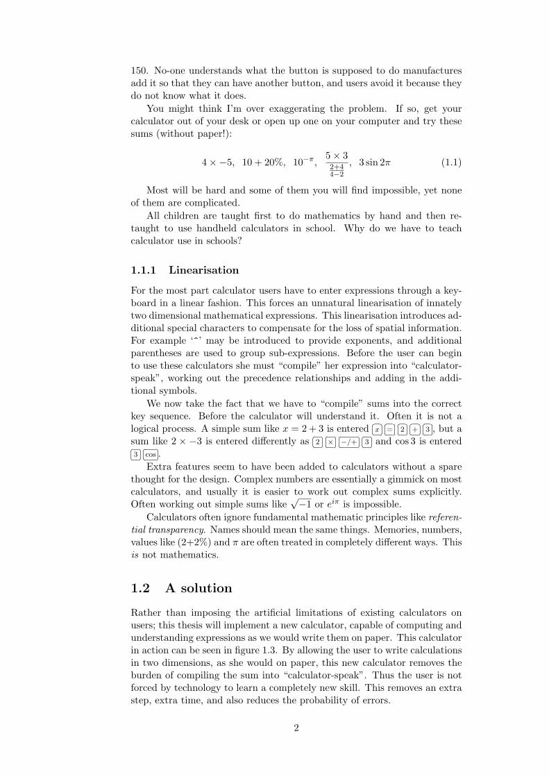
Rather than imposing the artificial limitations of existing calculators onusers; this thesis will implement a new calculator, capable of computing andunderstanding expressions as we would write them on paper. This calculatorin action can be seen in figure 1.3. By allowing the user to write calculationsin two dimensions, as she would on paper, this new calculator removes theburden of compiling the sum into “calculator-speak”. Thus the user is notforced by technology to learn a completely new skill. This removes an extrastep, extra time, and also reduces the probability of errors.
2

The calculator developed in this thesis provides an intuitive interface,such that users who are not confident in using existing calculators, will beable to use and understand this calculator. The solution is to create acalculator that can work like a pad of paper. Anyone will understand howit works and be able to use it without training.
This calculator will consist of four distinct parts, these are shown infigure 1.2.
1. Segmentation
!
23
+ 4
92. Symbol recognition
!
23
+ 4
9
Brief Article
The Author
April 1, 2004
23 + 4√9
= 6 (1)
1
3. Expression recognition
Brief Article
The Author
April 1, 2004
23 + 4√9
= 6 (1)
1
4. Calculation
Brief Article
The Author
April 1, 2004
23 + 4√9
= 6 (1)
1
4. User Interface
1a.
1b.
2.
3.
Figure 1.2: The expression recognition process
1. A symbol recogniser that segments the strokes written by the user ona pen-based device, then determines which symbols have been written.
2. An expression processor which takes the symbols with their relativepositioning and size and provides the mathematical expressions theyrepresent.
3. A calculator that provides the answers to the expressions.
4. A user interface which provides a transparent interaction, from hand-writing to displaying the result, including the relevant feedback, to theuser, so they can understand what is being computed.
3
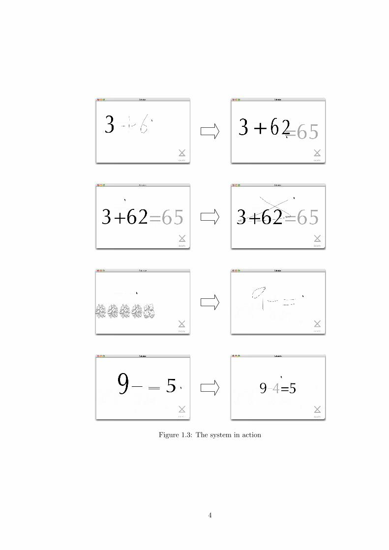
Figure 1.3: The system in action
4

This design of the calculator is reflected in the structure of this thesis.This thesis also describes the results from user testing that show that thenew calculator is more intuitive and easier to use.
1.3 Outline
The next chapter, chapter 2, describes in more detail the current methods,of entering mathematical expressions. Then chapters 3 and 5 cover the tech-nology that is used to provide expression recognition systems, this dividesinto two distinct parts. Chapter 3 covers symbol recognition and chapter 4expression recognition. Chapter 5 describes in detail the specific algorithmsused to create a new calculator. Chapter 6 covers the method of calculatingand answer and chapter 7 the pen-based user interface.
The user testing and results are reported on in chapters 8 and 9. Chapter8 describes the testing and chapter 9 describes the results.
Chapter 10 discusses the direction further development could take. Thefinal chapter, chapter 11, summarises the findings and contributions of thisthesis and concludes.
Figure 1.4: A complex example of a parsed expression
5

Chapter 2
Existing methods
This section discusses existing methods used for mathematical expressionentry into a computer. Some are used specifically to do calculations, andothers are used just to typeset documents. The three main methods for en-tering mathematical expressions are described, linear interfaces, template,and visual methods. Any of these methods can be used to provide an inter-active calculator; however, some are more suitable than others.
A useful paper by Kajler and Soiffer [22] covers the area, it gives agood overview of the techniques and design involved in interface systems foralgebra entry. They concentrate on template based systems, though theydo touch on pen and voice.
2.1 Linear Interfaces
A linear interface provides a means to enter expression s as a sequence ofcommands, for instance
� �2� �� �
+� �� �3� �� �� �� �
4� �.2.1.1 Simple linear expressions
Any simple pocket calculator requires expressions to be entered as a simplelinear sequence of operands and operators. The simplest calculators haveno concept of precedence or parentheses, and the more complex provideoperators for powers and trigonometric functions. Thus 2,+, 3,×, 4 can becalculated as either 20 or 14, depending on the calculator.
However expressions are not linear, and therefore they have to be con-verted so that the calculator can understand them. This processes of lineari-sation or compilation has to be done before the calculation. For instance,equation 2.1 has to be written in linear form as (2+3^3)/(1+1/2).
2 + 33
1 + 12
(2.1)
For simple handheld calculators this is nearly impossible to calculate,because they lack the ability to cope with brackets or precedence. Theequation would have to be entered as
� �MC� �� �
1� �� �/� �� �
2� �� �+� �� �
1� �� �M+� �� �
C� �� �3� �� �� �� �
3� �� �� �� �
3� �� �+� �� �
2� �� �=� �� �
/� �� �MR� �, a little convoluted! The majority of more complex linear
interfaces will understand a simple linearisation of the expression. But morecomplicated functions, or notations such as log or
∫, often have unusual and
strange input command sequences that has to be learnt.
6

2.1.2 Reverse Polish NotationPostfix notation wasdevised in 1920 bythe Polish mathemati-cian Jan Lukasiewicz.RPN was invented byCharles Hamblin in themid-1950s, to enablezero-address memorystores. It was first usedas a user interface forthe HP-35 handheldscientific calculator inthe late 1960’s.
Reverse Polish Notation (RPN), or postfix notation, is an arithmetic formulanotation, in which the operands precede the operator, thus removing theneed for parentheses. For instance the expression 4 × (2 + 3) would beentered as
� �4� �� �
2� �� �3� �� �
+� �� �� �.
Whilst this provides a more efficient way both to enter the formula and tocalculate the expression (RPN is very easy to calculate on a stack based ma-chine), the system is unintuitive and many people struggle with it. Ratherthan enabling users to more easily calculate expressions, RPN imposes fur-ther artificial limitations that the user has to overcome. Because of thisRPN is declining in popularity.
2.1.3 LATEX
LATEX [23] is a document preparation system for the TEX typesetting pro-gram. It is popular among mathematicians and scientists; mainly becauseof its high typesetting quality and the ease of including mathematical ex-pressions.
Mathematical expressions are expressed in LATEX as a textual commandstring. It recognises simple linear expressions but for more complicatedexpressions the learning curve is steep and many different commands mustbe learnt. As a typesetting program LATEX supports many different ways ofwriting the same expression and is not designed for parsing the expression.Equation 2.1 above, can be expressed as \frac{2+3^3}{1+\frac{1}{2}}.More complicated expressions can run to many lines.
2.1.4 Mathematica, Maple et al.
Mathematica [32] and Maple [29] are two examples of general purpose com-puter algebra systems. Although both at one point required a linear ex-pression entry, they now provide a template based entry system as well (seebelow, section 2.2). The expressions being entered in these software pack-ages were becoming too complex, to enter quickly and accurately enter in alinear form.
Each software package has its own proprietary format for entering ex-pressions. An example of Mathematica input to integrate an expression isIntegrate[(4x^3/Log[x]),{x,10,20}].
2.2 Template based interfaces
Template based interfaces are becoming more common as users require amore productive interafce to enter mathematical expressions. A templateeditor has been a part of Microsoft Word since 1993 [36], and many computeralgebra systems such as Mathematica provide template interfaces. LyX [28]provides a template based interface for mathematical expression entry forLATEX.
The basic idea of a template editor is to allow the user to constructthe equation by using templates of different mathematical expressions. Ba-sic operations such as addition and multiplication can be entered from thekeyboard. Operations which are not on the keyboard, or that are two-dimensional in nature (including fractions, exponentiatio, and integration),
7
are entered by using a template. The templates contain place-holders fornumbers or further templates. Templates are typically added through se-lection from a toolbar or palette, and selected using the arrow keys or themouse. The user can therefore build up an equation recursively, by addingtemplates within templates.
Figure 2.1 shows a screenshot of a half-entered expression in Microsoft’stemplate based equation editor. At the top of the window is a toolbar thatprovides the templates for the editor. The rest of the window shows theequation as it stands so far. The grey boxes are the placeholders for furthertemplates or simple expressions.
Figure 2.1: Screenshot of Microsoft’s Equation Editor.
2.3 Visual entry
Mathematical expressions use a two-dimensional structure of symbols toconvey information, so it is natural to use a two dimensional entry method.Understanding a mathematical expression requires both symbol and struc-tural recognition. These two activities are performed by all complete math-ematical expression recognition systems.
Blostein [6] divides the mathematics recognition problem into six pro-cesses, which are outlined below.
• Symbol recognition
– Pre-processing — noise reduction, de-skewing, etc.
– Segmentation, to isolate symbols
– Recognition of symbols
• Expression recognition
– Identification of spatial relationships among symbols
– Identification of logical relationships among symbols
8

– Construction of meaning
Since the 1960s a lot of research and time has gone into recognising math-ematical expressions using computer vision. This has been motivated by anumber of reasons; originally the main purpose was to digitise mathematicaldocuments, such as integral tables. Recently, as technology has progressed,especially as pen based interfaces have become more common, some of thefocus has moved towards hand-written formula entry methods. The formeruses off-line data and the latter on-line data where temporal informationabout the input is available.
2.3.1 Off-line
Off-line recognition usually involves digitising mathematical documents thathave already been written, and then analysing them. Digitising typesetdocuments has been an area of research for some time, Anderson [2] wasusing syntax directed recognition in 1968. Typeset mathematics has a farmore rigourous and consistent nature than hand-written expressions, in bothlayout and apperance. Thus different methods are more suited to recognisinghand-written and typeset expressions.
2.3.2 On-line
On-line processing is almost always by necessity hand entered expressions.These are entered though a pen and tablet interface, such as a Wacom tablet[53], or by using other dedicated hardware.
The advantage of pen based systems over other methods of expressionentry is their natural and intuitive interface. Most users are accustomedto writing mathematical expressions on paper, and a pen based interfaceutilises a symmetry with pencil on paper. Users are therefore capable ofusing their existing experience, reducing the need to learn new information.A pen-based system also provides an advantage over real paper, because ofthe power it has to manipulate and solve mathematical expressions.
A disadvantage of pen-based systems is that the inconsistency of howusers write mathematical expressions makes them extremely hard to recog-nise. The system has to deal with an arbitrary order of entry, the diversenature of the same symbols, and a rough positioning of the various elementsof the expression.
There are several existing implementations of pen based expression entrysystems, these are listed here. These implementations are discussed furtherin the next two sections.
• Freehand Formula Entry System (FFES) is a complete system for for-mula entry and conversion to LATEX [47]. FFES makes use of severaldistinct components. Including Caltech Interface Tools (CIT) [13] thatprovides a nearest-neighbour symbol classifier
• DRACULAE (Diagram Recognition Application for Computer Un-derstanding of Large Algebraic Expressions) [43, 44] implements atree-transformation based approach to recognizing the syntax and se-mantics of mathematical expressions. It is an alternative expressionrecognition algorithm for FFES.
9

• Yuko Eto and Masakazu Suzuki [17] present a mathematical formularecogniser that uses minimal spanning trees to reconstruct the formula.
• Blostein and Schuerr [7] present a graph rewriting parser that uses agraph rewriting language, as do Lavirotte and Pottier [25].
• Littin [27] makes use of a modified grammar to parser his expressions.
2.4 Summary
This chapter has described existing methods for entering mathematical ex-pressions, linear entry, template interfaces and visual on-line pen based in-terfaces. Linear entry methods can be powerful but are always limited bytheir structure. Symbolic manipulation programs such as Mathematica nowsupport template based entry methods to overcome the limitations of a lin-ear entry. Template based entry allows a more natural two dimensionalmethod of construction of expressions in two dimensions but is still fairlyawkward, and has not found widespread use.
Pen based mathematical expression entry systems. on the other hand,attempt to provide a completely natural method of input. However thetechnology and ideas are relatively young and are still an area of activeresearch. A pen based interface is utilised for the calculator developed inthis thesis, because it provides a natural method that allows anyone to useit without training.
10

Chapter 3
Symbol recognition
1. Segmentation1a.
!
23
+ 4
92. Symbol recognition1b.
Figure 3.1: Symbol recognition.
Symbol recognition is the segmentation and recognition of the users input,used to isolate symbols and then determine their meaning. This covers thefirst three points from section 2.3. Symbol recognition solely recognises thesymbols, it does not interpreting them within their context. For example‘–’ has only one meaning, a horizontal line. Its semantic meaning (minus ordivision) is determined later within the context of the whole expression.
Symbol or pattern recognition has been an active area of research sincebefore computers were invented and has been attempted using many dif-ferent methods. The most common methods are briefly described here,examining the benefits and detriments of each for use with handwriting.The different recognition methods can be roughly classified into three majorgroups: statistical, structural and syntactic, and model matching methods.Different methods can be combined. For example, a two stage classifica-tion process might use a simple and fast pre-classification before the finalclassification is done.
Symbol recognition of mathematics, even typeset mathematics, is a hardtask. It is difficult because of the large character set, and the variety of dif-ferent typefaces and font sizes. Within typeset mathematics this is restrictedto a smaller subset of possibilities than is encountered by hand-written ex-
11
pressions.With typeset data, raw pixel input is segmented into symbols and then
recognised. For on-line data character strokes are grouped into symbolsand then recognised. Problems occur because of the wide range of ways ofwriting symbols and the numerous different ways of segmenting the stokesinto symbols.
This chapter will deal briefly with some of these issues facing symbolrecognition, symbol segmentation and finally the three areas of recognitionmethods mentioned above.
3.1 Issues with symbol recognition
3.1.1 Noise
Noise is often removed in a pre-processing step before recognition to makerecognition easier. It should remove dust and specks. This processing stephas to be able to differentiate between small mathematical symbols (such asdots and commas) that are notation and noise. Differentiating noise fromsymbols is a hard task and often needs to be integrated semantically intothe expression parser.
Fortunately this is a more significant problem for processing scanned in-put, where noise occurs during the scanning process. Using a pen and tabletinterface as on-line input there is no noise except when the user accidentallydraws on the tablet. This will not often occur, and the user will be able tonotice when it happens and correct it.
3.1.2 Segmentation
Brief Article
The Author
March 31, 2004
1 < x
kx
1
Brief Article
The Author
March 31, 2004
1 < x
kx
1
Ambiguous expression
Possible segmentations
Multiple interpretations
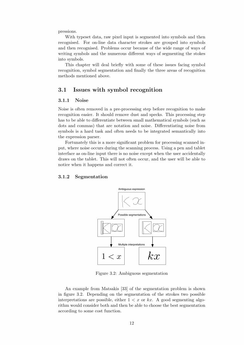
Figure 3.2: Ambiguous segmentation
An example from Matsakis [33] of the segmentation problem is shownin figure 3.2. Depending on the segmentation of the strokes two possibleinterpretations are possible, either 1 < x or kx. A good segmenting algo-rithm would consider both and then be able to choose the best segmentationaccording to some cost function.
12

3.1.3 Non-contiguous symbols
Non-contiguous symbols are symbols like ‘i’ and ‘t’, where the whole symbolis often not written in one stroke. In fact, a writer often dots the i’s or crossesthe t’s after finishing the whole word. These cause problems in an on-linesituation when segmenting symbols. The computer has to wait for the userto finish the symbol at some undetermined point in the future before it canrecognise it.
A simple way to handle this is to recognise the symbols, but to allowalteration later by the addition of a dot or cross. Both ‘i’ and ‘t’ can berecognised as an ‘l’, until the user alters it by adding an extra stroke.
3.1.4 Cursive writing
The majority of mathematical notation can not be written in a cursive formand is usually printed. Each symbol is written separately from every otherso that each stroke in an expression belongs to only one symbol.
However some of the functions like the trigonometric functions (e.g., sin,tan) and logarithms can be written cursively. With large vocabularies mostmethods of handling cursive writing split the cursive words into charactersbefore recognition. The majority of mathematics recognition implementa-tions simply enforce printed characters; for mathematics this is not much ofa disadvantage but it is still an awkward interface for the user.
The small vocabulary of valid cursive words used in mathematics provideanother solution; each word can be recognised in its entirety as a cursivestroke. For example there would be a cursive-sin path that recognises theentirety of sin written cursively. This is also awkward and handles differentwriting styles badly. The usual solution is to cut the stroke into characterswhich are then recognised separately.
3.1.5 Overlapping symbols
Separating the data for distinct symbols from each other often requires asemantic understanding of the structure of the formula. With on-line dataonly strokes need to be segmented not pixels; this is simpler. The small setof valid composite symbols (×,=, 4 . . .) constructed of more than one strokealso make this a simpler problem. The geometric relationship of overlappingsymbols is a different problem, and is discussed in section 4.1.4.
3.1.6 Symbols
Some symbols have a large range of possible scales and aspect ratios, forexample brackets,
∑, and √. This makes them harder to recognise. For on-
line hand-written input the problem is more complex, because the variationin symbol style is greater.
3.2 Segmentation
Symbol segmentation needs to occur before recognition. It groups togetherthe data corresponding to separate symbols. Segmentation can also involve
13

segmenting the entire document or input into text, graphics and mathemat-ics. Segmentation is easier with on-line data, but it still has to overcomesome of the issues mentioned in the last section, section 3.1.
The total cost of any segmentation of the mathematical expression canbe calculated as the sum of the costs of each symbol identified. The costof an individual symbol can be calculated in several ways, however, a goodmethod is to use the probability of the best interpretation of the strokesgiven by the symbol recogniser.
3.2.1 Exhaustive search
Given that the number of strokes that can be combined into a symbol isreasonably limited to three or four, the complexity of an exhaustive searchis not exponential but polynomial — roughly O(n4), where n is the numberof strokes. For simple equations of even five or ten strokes, this becomesimpractical and inefficient. Thus ways of constraining the search have to beused, the next two sections outline two possible constraints.
3.2.2 Temporal ordering
Temporal ordering is a simple constraint on the segments allowed. Onlystrokes written consecutively in time may potentially be part of the samesymbol. The constraint creates a linear string structure, and segmentationtakes the form of partitioning this string, giving a much improved complexityof O(n). This method does not allow for non-contiguous symbols.
3.2.3 Minimal spanning tree
The problem with temporal ordering is that it is overly restrictive. To dealappropriately with non-contiguous symbols, or augmented symbols (con-verting a “<” into a “6”) the constraint needs to be less restrictive. Aconstraint that matches the criteria is a minimal spanning tree (MST).
A spanning tree of a connected undirected graph is a set of edges whichconnect all the vertices of the graph, such that no cycle exists between anytwo vertices. Within a weighted graph the MST is a spanning tree whosesummed edge weight is less than or equal to that of all other spanningtrees in the graph. Minimal spanning trees can be efficiently computed byusing either Kruskal or Prim’s algorithms. These are both greedy algorithmsthat run in polynomial time, or more accurately O(m log n) where m is thenumber of edges and n is the number of vertices.
The minimal spanning tree for a set of strokes can be thought of as theminimal spanning tree of a fully connected graph, where the strokes are thevertices, and the weight of an edge is the distance between the strokes.
Once the minimal spanning tree has been found, segmentation can beconstrained to only consider partitions that form connected subtrees in theMST. For example in figure 3.3 there are seven symbols, four of which con-tain double strokes, ‘x’ twice, ‘=’ and ‘4’. For a correct segmentation to befound these strokes need to be connected in the spanning tree. The set ofconnected strokes is then explored and the cost is calculated for the possiblesegmentations. In figure 3.3 these edges do exist, so the correct segmentationis contained within the tree.
14

Figure 3.3: A minimal spanning tree
Matsakis [33] provides a good analysis of the complexity of using MSTs,where he shows that although the worst case is still exponential, the com-plexity in practice is often much closer to the best case of O(n).
3.3 Signal processing
The pattern recognition problem can be viewed as a signal processing prob-lem, where the closed contour of a pattern is considered as a periodic signal[41]. Such a signal can be expressed as a series of sums of complex numbersas given by the coefficient of the Fourier Series. The coefficients are thenused to calculate the distance between a feature vector and a generic vectorto be classified.
The Fourier coefficients can be used to define invariants under affinetransformations, such as rotation, scaling and translation. This is a usefulfeature for symbol recognition, because most symbols remain the same underaffine transformation. However, this invariance causes problems in the caseof the digits ‘2’ and ‘5’ as well as ‘6’ and ‘9’; it is also a problem for othersymbols such as the ‘×’ operator, which matches ‘+’. These ambiguitieshave to be resolved by other methods.
3.4 Statistical methods
Statistical methods recognise a character by choosing either the most prob-able character or choosing the character with the least probability of wrongclassification. Features of the characters such as loops or curvature are as-sumed to be variables with statistical distributions. Different classes havedifferent distributions. Several statistical methods are described in this sec-tion.
3.4.1 Simple statistical matching
Odaka et al. [16] describes a simple statistical method for on-line characterrecognition. Characters are first pre-classified by the number of strokes, theneach stroke is approximated by a small number of line segments of equallength. The final classification is chosen by the minimal distance betweenthe feature vector of the unknown character and the set of reference patterns.The feature vector of a character consisting of s strokes and n points is:
15

L = (x11, y11, x12, y12, ..., xsn, ysn) (3.1)The Mahalanobis dis-tance is the same as theEuclidean distance if thecovariance matrix is theidentity matrix.
The distance between a feature vector L and the reference pattern ofclass θ is the Mahalanobis distance:
D(L, θ) = (L−Mθ)C−1θ (L−Mθ)T (3.2)
where Mθ is the mean vector and C−1θ is the covariance matrix of the
reference class. The Mahalanobis distance takes the sample variability intoaccount, it weights the differences by the range of variability in the direc-tion of the sample point. Thus it is often used in computer vision systemsfor comparing feature vectors whose elements are have different ranges andamounts of variation.
Simple statistical matching can be used for any features of charactersnot just stroke points. For instance, the loops, cusps, and corners of thestroke could be used.
3.4.2 Hidden Markov ModelsHMMs were first usedby Markov himself in aletter sequence analysisof the text of EugeneOnegin in 1913. Sincethen they have been wellused in text analysis andspeech recognition.
A Hidden Markov Model (HMM) is a finite state machine in which thetransitions between states and the outputs are probabilistic rather thandeterministic. HMMs have been used for a number of years in speech recog-nition. The similarity of the speech recognition and handwriting recognitionproblems suggests that the solutions could be similar. Starner et al. [48]demonstrated this well. They used a HMM-based continuous speech recog-nition system to recognise on-line cursive handwriting. With only a simplechange to their model, altering the features used by the front end module,the system could recognise cursive handwriting with an word error rate of4.1%.
In a regular Markov model, the state is directly visible to the observer,and therefore the state transition probabilities are the only parameters. Ahidden Markov model adds outputs: each state has a probability distributionover the possible output tokens. Therefore, looking at a sequence of tokensgenerated by an HMM does not directly indicate the sequence of states.
Originally HMM-based systems were used to recognise entire words, how-ever with increased vocabulary, character models are now far more popular.Stroke models are also used, concatenated to form symbols.
When using HMMs for symbol recognition, the probability of each tran-sition is based on the occurrence of certain features. Low-level metrics suchas slope and curvature or more syntactic features such as cusps and loopscan be used. These probabilities can be trained into the model. When pre-sented with a sequence of observations of features from a symbol, we cancalculate the probability it was generated by an HMM. Each symbol hasits own HMM, and thus we can calculate the probability that an observedinput is a specific symbol. The set of symbols and probabilities can then bepassed on to the expression recognition module.
3.5 Structural and syntactic methods
Structural and syntactic methods are used for pattern recognition taskswhere the structure of the pattern is of principal importance for classifica-
16
tion.Syntactic methods use the features found in patterns as the primitives of
a formal language. The basic features are represented as terminal symbolsof the language, which are combined into the non-terminals according tothe grammar. Each class has its own grammatical rules and the pattern isclassified according to the syntactically corresponding class. Often existenceor absence of structural features is not enough to classify a pattern, thereforemore information on the relationship between features is needed.
Structural methods are based on a similar analysis of features, howeverthe classification is based on matching and decision rules rather than parsing.Recognition is performed in a hierarchical manner, using low-level featuresto pre-classify before considering higher level features and structures.
3.5.1 Picture Description Language
Picture Description Language (PDL) is a syntactic method introduced byShawn [45]. PDL uses straight line segments as primitives. These have headsand tails, four directions and three lengths. The grammar rules used in PDLdescribe how line segments can join together. Although this is a simplemethod it could be used (with some alteration) to recognise mathematics.
3.5.2 Elastic structural matching
Chan and Yeung [10] describe a structural method in which the unknownpattern is deformed if it does not match any of the classes. The primitivesor terminals of the grammar are line segments, a counter-clockwise and aclockwise curve, a loop, and a dot. A character is composed of a sequenceof the base features.
Recognition is performed by choosing the first matching class. If nomatch is found the character is morphed until it matches a class. Morph-ing occurs in three stages, first by modifying the base features, then thedirection, and finally both structure and direction.
3.6 Model matching
Model matching is based on the assumption that hand-written charactersare distorted realisations of ideal models. At the training stage, templatesor ideal models are recorded. At the recognition stage these are comparedto the data to be recognised. A distance measure is then generated betweenthe data and the template using features from the data. This distance isused to generate a likelihood value indicating the closeness of the match.
3.6.1 Simple model matching
Similar to the feature vector of equation 3.1, a stroke can be defined as afeature vector of the x, y positions of the points that make up the stroke ofn points.
L = ((x1, y1), (x2, y2), ..., (xn, yn)) (3.3)
A simple distance measure between a feature vector L and the model Mis then written as:
17

D(L,M) =n∑
i=1
(Li −Mi)2 (3.4)
The distance measure is the sum of the squares of the distance betweencorresponding points on the data and the model. Before this method canwork, some pre-processing needs to be done. The data is scaled to themodel’s size and then centred on top of the model. This is a very simpledistance measure and more complex features of the stroke could be usedsuch as curvature and timing.
3.6.2 Elastic matching
Originally used in speech recognition, elastic matching has found a use incharacter recognition. One problem with the simple matching above is thattwo models can look exactly alike and yet not match. The simple matchingscheme matches up points based on their index in the patterns, however theindices might not correspond. Elastic matching, also called dynamic timewarping, is a non-linear matching method that solves this problem.
Dynamic time warping can be used to compare all kinds of continuousfunctions of continuous parameters, for example position over time. It isbased on the idea that the underlying speed of the process can vary. Theeffect of this variation in one of the axes can be eliminated when comparingtwo functions if the parameter axes are warped. Thus elastic matchingis insensitive to the distortion caused by different writing speeds, and thevariation of the number and distribution of the sample points within a stroke.
Elastic matching uses dynamic programming methods to provide theoptimal time warping and point-to-point correspondence that minimises thedissimilarities.
A modified version of what Tappert [49] describes is presented here.First, the characters are pre-processed. The data points are resampled sothat they are spaced evenly in distance instead of time. Then they arenormalised to a specified height. The feature vector of a stroke consists ofthe slope angle φi of a curve and the normalised coordinates xi, yi
The distance between two points, Pi = (φi, xi, yi) and Pj = (φj , xj , yj)is given by the equation:
d(i, j) = α×min{|φi − φj |, 2π− φi − φj}+ β × (|xi − xj |+ |yi − yj |) (3.5)
where α and β are coefficients that can be determined to best minimisethe intraclass distance and maximise the interclass distance between thesymbol models classified according to their symbol.
The distance between an unknown character and the model is now foundby minimising the following equation:
D = minw∈W
n∑i=1
d(i, w(i)) (3.6)
where W is the set of all possible time warping functions w defininga point-to-point correspondence between the unknown and the model andn is the number of points in the unknown character. The time warpingfunctions are constrained by boundary conditions. In this case, the boundary
18

condition ensures that the end points are matched against each other andthat the function w is continuous and monotonically increasing. All thepoints in the unknown are matched, but points in the model can be skipped.This is called band-limited time warping.
Thus using dynamic programming the distance can be computed recur-sively in this way:
D(1, 1) = d(1, 1)D(i, j) = d(i, j) + min{D(i− 1, j), D(i− 1, j − 1), D(i− 1, j − 2)}
D = D(n, m) (3.7)
where D(i, j) is the cumulative distance up to the point i. D(N,M)examines all the possible paths from (n, m) down to (1, 1) recursively, andthe path with the minimal cumulative distance is chosen as the time warpingfunction.
3.6.3 Shape metamorphism
A physics based shape metamorphism method is described by Pavlidis et al.[39]. Their method uses a distance measure based on the “degree of mor-phing” between an unknown curve and a template curve. A physics-basedapproach substantiates the “degree of morphing” as a deformation energyand casts the problem as an energy minimization problem. The curve is splitat key points, corners and points of low curvature. The morphing is thendone by stretching and bending these segments and the energy needed foundusing dynamic programming techniques. The shape is selected based on theminimal degree of morphing or energy required to change the unknown intoa recognised template.
3.7 Summary
In this chapter the main problems and methods for both symbol segmenta-tion and recognition have been discussed. Segmentation combines strokesinto symbols minimising the total cost. Brute force symbol segmentation istoo complex for large expressions, therefore two simple solutions were pre-sented that restrict the segmentation. These were temporal ordering anduse of a minimal spanning tree. A temporal solution is preferable becauseit allows on-line segmentation to take place.
Symbol recognition classifies the strokes after segmentation. Three mainmethods were presented: statistical, structural and syntactic, and modelmatching methods, each with examples. Model matching is used for symbolrecognition for the system designed in this thesis, it is simple and effective.
The methods used for segmentation and recognition are described ingreater detail in chapter 5.
19

Chapter 4
Expression recognition
!
23
+ 4
9
Brief Article
The Author
April 1, 2004
23 + 4√9
= 6 (1)
1
3. Expression recognition2.
Figure 4.1: Expression recognition.
The purpose of expression recognition is to determine the meaning of theexpression given the symbols and their relative placement and sizes. Thischapter will cover some of the issues that make expression recognition dif-ficult, before covering the main categories of existing techniques and somemore esoteric methods.
4.1 Issues with expression recognition
Mathematical expressions are not easy to understand. Mathematical nota-tion is very subtle, and makes use of relative sizes and placements continu-ally. Without the context it is often hard even for humans to comprehendsome mathematical notation.
4.1.1 Ambiguous symbols
In mathematics most symbols have a well defined meaning. ‘2’ always meanstwo and ‘+’ always mean plus. However several common symbols have anambiguous meaning outside of their context. A dot can represent a decimalpoint, a multiplication or an annotation like ‘x’; a horizontal line can be aninfix subtraction operator, a prefix negation, a fraction bar or part of a morecomplicated symbol such as ‘=’ or ‘6’.
The sole way of determining the meaning of these symbols is from theircontext within the whole expression. The ambiguitity of these symbolstherefore must be addressed during a structural and semantic analysis ofthe expression.
20
4.1.2 Ambiguous spatial relationships
Much of the meaning of a mathematical expression is contained within itsspatial relationships. Exponentiation and multiplication are implied by therelative positions of symbols, in contrast to operations such as additionwhere the ‘+’ symbol is always placed between its two operands. Impliedoperations are hard to determine as they are implied by a rough spatialpositioning.
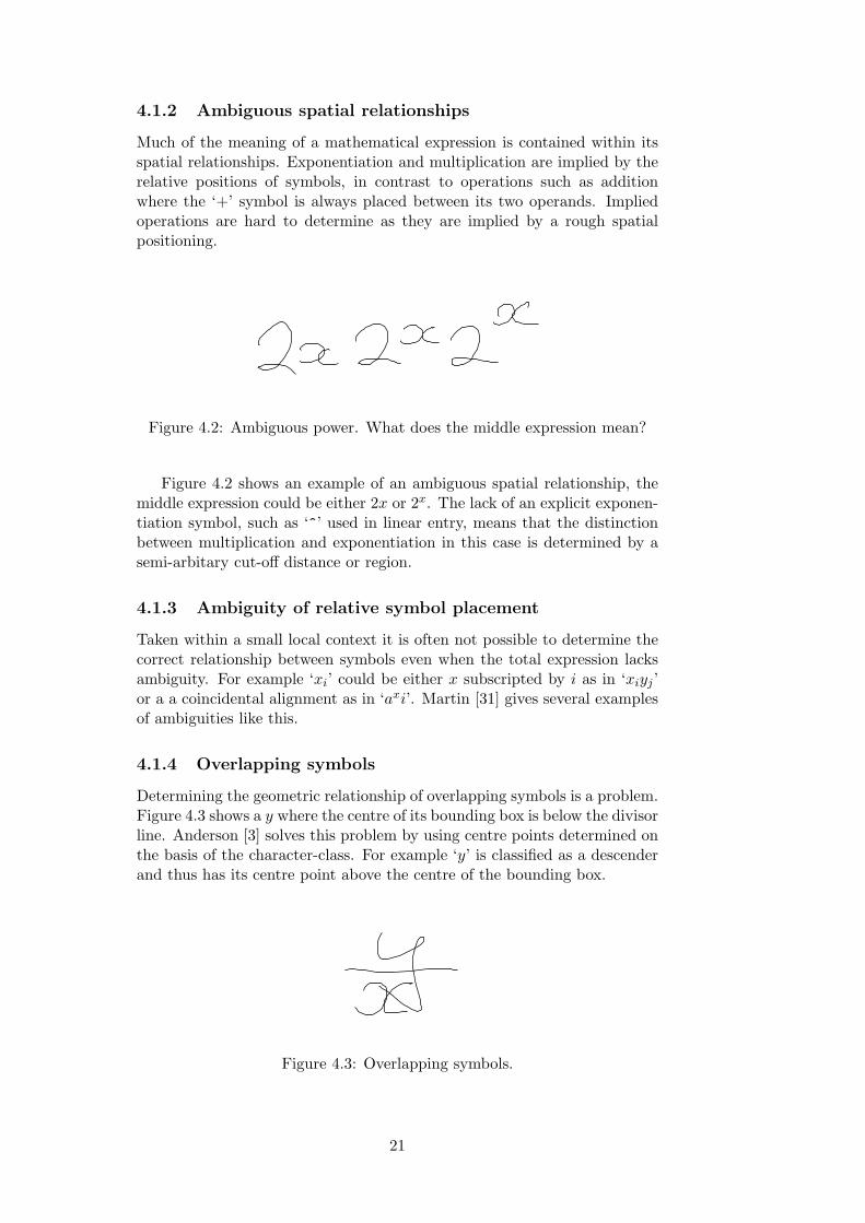
Figure 4.2: Ambiguous power. What does the middle expression mean?
Figure 4.2 shows an example of an ambiguous spatial relationship, themiddle expression could be either 2x or 2x. The lack of an explicit exponen-tiation symbol, such as ‘^’ used in linear entry, means that the distinctionbetween multiplication and exponentiation in this case is determined by asemi-arbitary cut-off distance or region.
4.1.3 Ambiguity of relative symbol placement
Taken within a small local context it is often not possible to determine thecorrect relationship between symbols even when the total expression lacksambiguity. For example ‘xi’ could be either x subscripted by i as in ‘xiyj ’or a a coincidental alignment as in ‘axi’. Martin [31] gives several examplesof ambiguities like this.
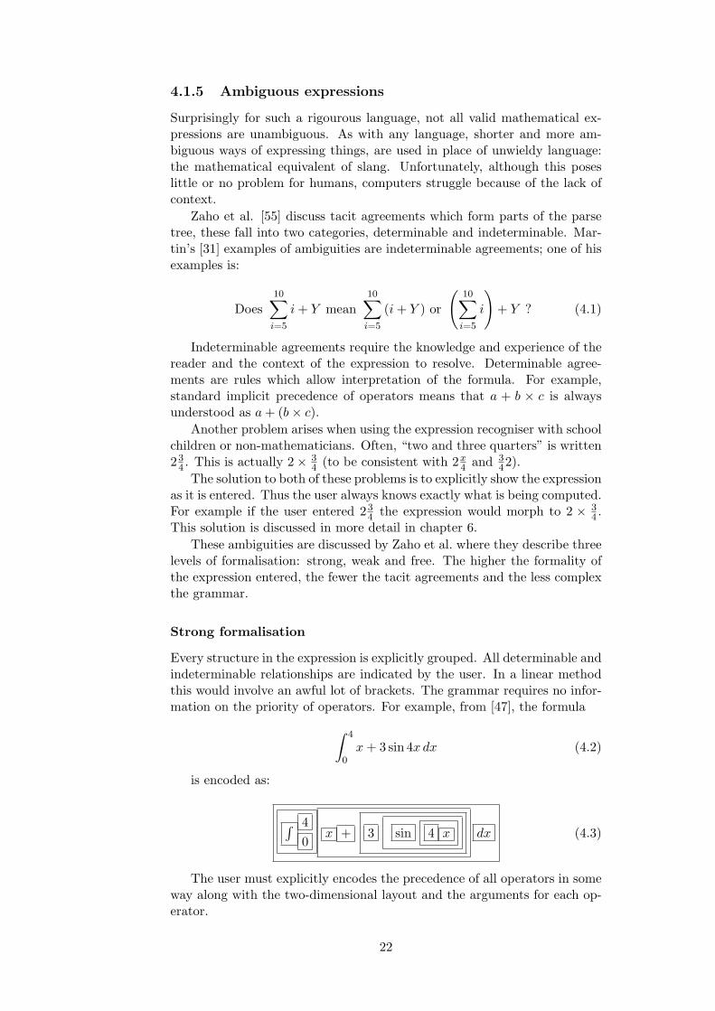
4.1.4 Overlapping symbols
Determining the geometric relationship of overlapping symbols is a problem.Figure 4.3 shows a y where the centre of its bounding box is below the divisorline. Anderson [3] solves this problem by using centre points determined onthe basis of the character-class. For example ‘y’ is classified as a descenderand thus has its centre point above the centre of the bounding box.
Figure 4.3: Overlapping symbols.
21
4.1.5 Ambiguous expressions
Surprisingly for such a rigourous language, not all valid mathematical ex-pressions are unambiguous. As with any language, shorter and more am-biguous ways of expressing things, are used in place of unwieldy language:the mathematical equivalent of slang. Unfortunately, although this poseslittle or no problem for humans, computers struggle because of the lack ofcontext.
Zaho et al. [55] discuss tacit agreements which form parts of the parsetree, these fall into two categories, determinable and indeterminable. Mar-tin’s [31] examples of ambiguities are indeterminable agreements; one of hisexamples is:
Does10∑i=5
i + Y mean10∑i=5
(i + Y ) or
(10∑i=5
i
)+ Y ? (4.1)
Indeterminable agreements require the knowledge and experience of thereader and the context of the expression to resolve. Determinable agree-ments are rules which allow interpretation of the formula. For example,standard implicit precedence of operators means that a + b × c is alwaysunderstood as a + (b× c).
Another problem arises when using the expression recogniser with schoolchildren or non-mathematicians. Often, “two and three quarters” is written23
4 . This is actually 2× 34 (to be consistent with 2x
4 and 342).
The solution to both of these problems is to explicitly show the expressionas it is entered. Thus the user always knows exactly what is being computed.For example if the user entered 23
4 the expression would morph to 2 × 34 .
This solution is discussed in more detail in chapter 6.These ambiguities are discussed by Zaho et al. where they describe three
levels of formalisation: strong, weak and free. The higher the formality ofthe expression entered, the fewer the tacit agreements and the less complexthe grammar.
Strong formalisation
Every structure in the expression is explicitly grouped. All determinable andindeterminable relationships are indicated by the user. In a linear methodthis would involve an awful lot of brackets. The grammar requires no infor-mation on the priority of operators. For example, from [47], the formula∫ 4
0x + 3 sin 4x dx (4.2)
is encoded as:
∫ 40
x + 3 sin 4 x dx (4.3)
The user must explicitly encodes the precedence of all operators in someway along with the two-dimensional layout and the arguments for each op-erator.
22

Weak formalisation
The user has to specify fewer relationships in a weak formalisation system.The grammar encodes the precedence of operators. The resulting weakgrammar uses grammatical categories like sentence, relation, term and factorto encode the priorities. The example formula is now entered as:
∫ 40
x + 3 sin 4 x dx (4.4)
This level of formalisation is similar to that of template based equationediting.
Free formalisation
Free formalisation requires fewer specified relationships still, the only struc-ture required is that specifying the layout of the formula.
∫ 40
x + 3 sin 4 x dx (4.5)
A grammar to parse free expressions has to be extended to determinethe start and end of groups of symbols, such as brackets. In the examplethe grammar has to determine the grouping for sin and the integrand.
No formalisation
No formalisation in which the system determines all relationships betweensymbols is the ideal situation. The user can concentrate on the meaning ofthe expression without worrying about explicitly defining its layout. Thisis the system implemented by most expression parsers, although often theposition of symbols is restricted.
4.1.6 Badly written expressions
It is possible to write expressions whose meaning is simply indeterminable.For example a ambiguous typeset expression is shown in equation 4.6.
a
b
c
(4.6)
The solution in this case would simply be to deterministically choose oneor the other interpretation, a/(b/c) or (a/b)/c. There is no right or wronganswer. Whilst the above equation was actually well formatted but am-biguous, the problem is increased when users write expressions that are justmeaningless. Equation 4.7 is an example. However dealing with these oddexpressions is a distant second objective to dealing with correctly formattedexpressions properly.
√4 = x + 2 (4.7)
23

In equation 4.7, perhaps a good parser would attempt a recognition andachieve
√4 = x + 2. Users of pen-based systems will enter expressions
like this. Knowing that these expressions exist and can be entered is moreimportant for algorithm design than dealing with them in a sensible way.
4.1.7 Little redundancy in mathematical notation
Mathematical notation does not contain much redundancy, unlike musicnotation, where information is duplicated to aid reading. For example, barlines are redundant but provide a cross-check with the rest of the notation.The relative lack of redundancy in mathematics means that less informationis available for checking the interpretation of a expression.
4.2 Top-down versus bottom-up
Formula recognition methods tend to rely solely on one or other parsingmethod: top-down or bottom-up. Top-down parsing, or goal directed pars-ing, builds the parse tree from the root down to the leaves. Bottom-upparsing, on the other hand, constructs the parse tree from the input begin-ning at the leaves and working up towards the root. The recursive tree-likenature of mathematical expressions means that either method can be suc-cessfully used to parse them.
Bottom-up parsing is the style adopted by the majority of people de-veloping mathematical expression parsers. The top-most operator is de-termined by the surrounding symbols as the parse tree is built. A benefitof using bottom-up parsers is that they are data-driven, which means thatthe parsing is directed by the data. For instance, if no “×” exists in theexpression, then it is never parsed or looked for.
This benefit means that bottom-up parsers appear to be better suited tothe recognition of mathematical expressions as the input symbols drive theparser. The majority of existing expression parsers are bottom-up parsers.However, bottom-up parsers are inefficient when unnecessary reductions areperformed, and can create a lot of backtracking. In multi-dimensional do-mains, like mathematics, there tends to be no specific starting point, asthere is in linear structures (the end points). Therefore, bottom-up methods,which group together recognised sub-components, world appear to performbetter in these extend domains.
Top-down parsers have several disadvantages that have reduced theirappeal relative to bottom-up parsers. They have difficulties in parsing in-complete or fragmentary data, or parsing inputs that fall outside the gram-mar. They still need to backtrack when the wrong rule is chosen and rulesare tried regardless of the input data. Many rules are often tried that donot play a role in the actual derivation. This inefficiency is often stated asa reason to ignore top-down parsers. However mathematics consists of arelatively small grammar, and efficiency is not of prime concern: the mosteffective method should be chosen.
4.3 Methods
This section provides an overview of existing methods to parse mathemat-ical expressions. The methods described in this section differ in their per-
24

formance, power and ability to handle handwriting. The benefits of each isdescribed.
Blostein and Grbavec [6] provide a good overview of the categories ofexisting mathematical expression parsers.
4.3.1 Modified grammars
One method takes existing one-dimensional string grammars, and appliesthem to the multi-dimensional domain of mathematics. Geometric relation-ships between symbols can be encoded as extra terminals or as additionalchecks on the production rules. This technique is only useful with on-lineordered input. Time is used to order the symbols before parsing, and ex-pressions are restricted to a non-arbitrary order of entry.
Littin [27] uses a SLR(1) parser with additional tests on the geometric re-lationship of the symbols. He achieves this by first creating a SLR(1) parser,which he then extends to contain geometric tests where necessary. The ge-ometric tests check that the symbols are in the correct locations. Tolerancefor sloppiness is implemented by thresholds on the geometric relationships.
To use this modified grammar the user has to enter the symbols for anexpression in a predefined order. For example,
a + b
c− d(4.8)
has to be entered in the order a, +, b, —, c, -, d. This ordering is usedto produce a string which can then be parsed by the SLR(1) parser. Littinjustifies this restriction by the fact that people tend to enter expressionsusing similar orderings. While this is a reasonable assumption the majorityof the time, it is an extremely unintuitive restriction on the user. Further-more, editing during or after entry is limited to the deletion or alteration ofthe most recently written symbol. Thus Littin has constructed a expressionentry system rather than an editing system.
The advantage of using a SLR(1) parser for this problem is its time andspace efficiency. The computational complexity of Littin’s system is O(g),where g is the number of symbols in the input formula. It is however severelyrestricted in its usefulness.
4.3.2 Syntactic Methods
Syntactic methods use a top-down approach. They utilise the structure ofan expression to direct the parse.
One of the major problems with the syntactic approach is that it strug-gles to handle errors or uncertainty from symbol recognition. It also hasproblems because the tests are based on bounding-box coordinates whichprovide a fairly crude recognition of spatial relationships. For example, alimit expression under a
∑is required to have an x-extent that lies strictly
within the∑
’s x-extent.
Coordinate grammars
Coordinate grammars are used by Anderson [4] for both arithmetic andmatrix mathematical notation recognition. Each coordinate grammar pro-duction divides up the set of symbols into subsets.
25

Each grammar rule starts with a set of symbols and a syntactic goal(e.g. FACTOR, DIVTERM, LIMIT). Each rule specifies how to subdividethe set of symbols into subsets each with their own subgoal. Partitioningconditions are used to describe spatial constraints. For example, the additionrule TERM subdivides the set of symbols into, the set of symbols to the left,and the set of symbols to the right of an addition symbol. Each of thesesubsets has a new subgoal FACTOR. If this production fails, there is noaddition symbol or no symbols to the right and left of the addition, thenthe parser tries an alternative.
Concatenation operators
Concatenation operators offer a geometric approach. Every symbol is con-tained within vertical or horizontal concatenations. For instance a + b
c isparsed as hcat(a,+,vcat(b,−, c)). This approach is used by Martin [30].When the concatenation operators are applied they define the subdivisionof the plane.Martin’s system from
1967 was one of the veryearliest systems of pars-ing mathematics. Structure specification schemes
Structural specification schemes are based on operators that divide the pat-tern into one or more sub-patterns. The implementation is based on Chang’s[11] scheme, which is described in depth in section 5.3.1.
4.3.3 Projection-profile cutting
Projection-profile cutting, also called structural analysis, determines thestructure of an expression through repeated horizontal and vertical projec-tions of the expressions image. Projection-profile cutting has been used ona whole range of document-image analysis applications. It has been used torecognise of music notation separating staves and isolating particular musicsymbols. Projection profiles have also been used to divide a page up intosections, columns and paragraphs.
Projection-profile cutting is applied recursively, creating a tree struc-ture representing the expression’s geometric structure. Each cut alternatesbetween projecting horizontally and vertically, and provides regions whichare subsequently cut into further sub-regions, down to the symbol level.Thus projection cutting creates a tree structure of horizontal and verticalconcatenation.
Figure 4.4 shows how a vertical projection profile cut is created. Theheight of the histogram is determined by the area of the symbols’ boxesabove it, but can also be determined by other factors such as the densityof pixels. The expression in figure 4.4 can be subdivided based on theminima of the histogram, producing three sub-regions: the integral symbol,the fraction and the differential. These can then be horizontally projected,thus providing the numerator and denominator of the fraction.
The disadvantage of projection-profile cutting is that special processingis needed for square roots and superscripts. It also has problems with sloppyhand-written expressions and skewed writing.
26
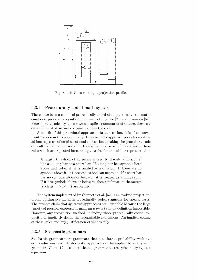
Figure 4.4: Constructing a projection profile.
4.3.4 Procedurally coded math syntax
There have been a couple of procedurally coded attempts to solve the math-ematics expression recognition problem, notably Lee [26] and Okamoto [52].Procedurally coded systems have no explicit grammar or structure, they relyon an implicit structure contained within the code.
A benefit of this procedural approach is fast execution. It is often conve-nient to code in this way initially. However, this approach provides a ratherad hoc representation of notational conventions, making the procedural codedifficult to maintain or scale up. Blostein and Grbavec [6] lists a few of theserules which are repeated here, and give a feel for the ad hoc representation.
A length threshold of 20 pixels is used to classify a horizontalline as a long bar or a short bar. If a long bar has symbols bothabove and below it, it is treated as a division. If there are nosymbols above it, it is treated as boolean negation. If a short barhas no symbols above or below it, it is treated as a minus sign.If it has symbols above or below it, then combination characters(such as =,>,6,⊇) are formed.
The system implemented by Okamoto et al. [52] is an evolved projection-profile cutting system with procedurally coded segments for special cases.The authors claim that syntactic approaches are untenable because the largevariety of possible expressions make an a priori syntax definition impossible.However, any recognition method, including those procedurally coded, ex-plicitly or implicitly define the recognisable expressions. An implicit codingof these rules and any justification of that is silly.
4.3.5 Stochastic grammars
Stochastic grammars are grammars that associate a probability with ev-ery production used. A stochastic approach can be applied to any type ofgrammar. Chou [12] uses a stochastic grammar to recognise noisy typesetequations.
27
For any given sequence of productions in a given parse the probabilityof this sequence can be calculated. The correct parsing is the parse withthe highest probability. These probabilities can be assigned by algorithmsworking from examples.
Stochastic grammars cope well with geometric tests. Symbols can beassigned a probability of having various geometric relationships. This re-flects the actual uncertainty of these relationships, as opposed to constraineddeterministic predicates for relationships. Another advantage is that thestochastic approach can take into direct account possible alternative andconfidence values from the output of the symbol recogniser. As a result thestochastic parser itself can choose the most likely alternative in the ambigu-ous case.
4.3.6 Graph rewriting
Graph rewriting is a general computational technique, information is repre-sented as an attributed graph, and is manipulated by updating the graphthrough graph rewriting rules. A graph rewriting rule (g ::= h) specifiesthat a sub-graph of the main graph isomorphic to g can be replaced by an-other graph h, within the main graph. Graph rewriting has been used fora wide range of tasks, including recognising music [5], schematic diagraminterpretation [8], flow chart description, organic chemistry molecules andimages of particle trajectories from physics experiments.
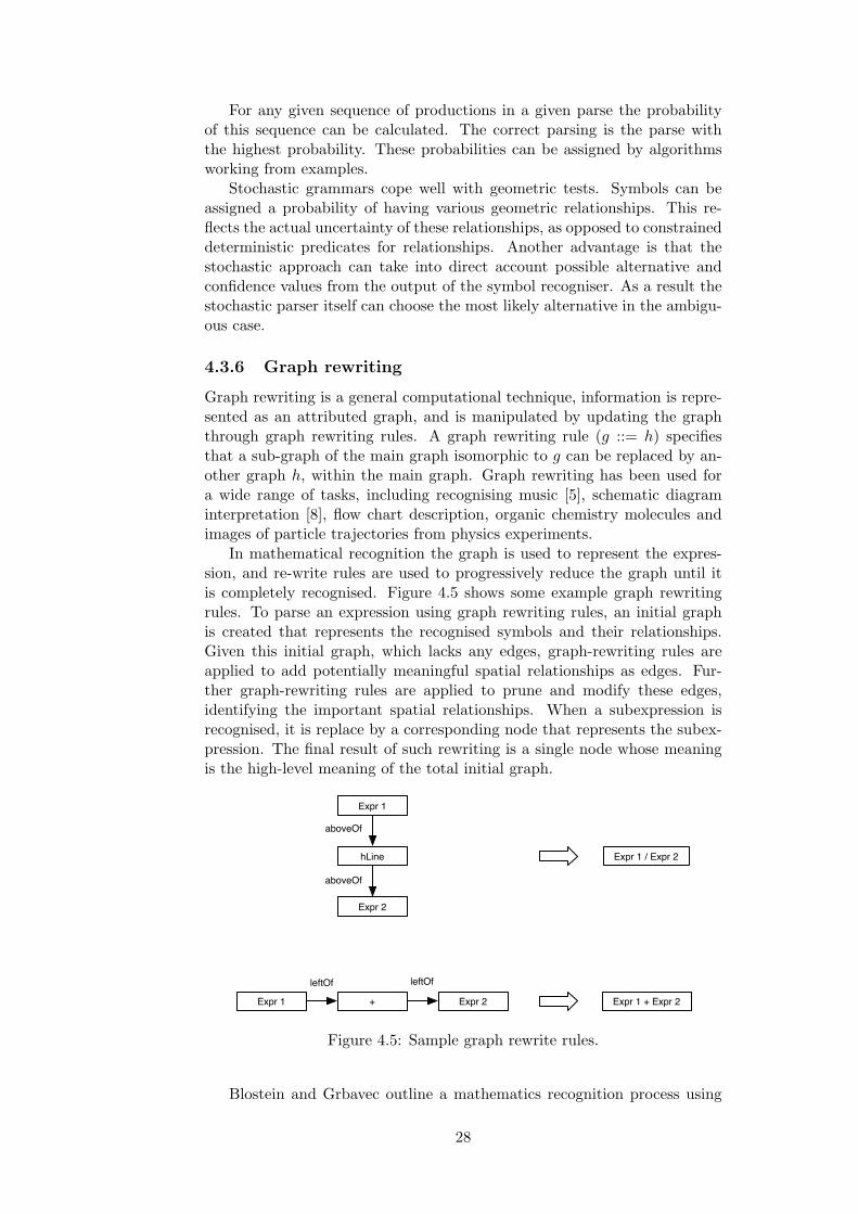
In mathematical recognition the graph is used to represent the expres-sion, and re-write rules are used to progressively reduce the graph until itis completely recognised. Figure 4.5 shows some example graph rewritingrules. To parse an expression using graph rewriting rules, an initial graphis created that represents the recognised symbols and their relationships.Given this initial graph, which lacks any edges, graph-rewriting rules areapplied to add potentially meaningful spatial relationships as edges. Fur-ther graph-rewriting rules are applied to prune and modify these edges,identifying the important spatial relationships. When a subexpression isrecognised, it is replace by a corresponding node that represents the subex-pression. The final result of such rewriting is a single node whose meaningis the high-level meaning of the total initial graph.
aboveOf
aboveOf
leftOf leftOf
Expr 1
hLine
Expr 2
Expr 1 / Expr 2
Expr 1 + Expr 2 Expr 1 + Expr 2
Figure 4.5: Sample graph rewrite rules.
Blostein and Grbavec outline a mathematics recognition process using
28
graph rewriting in [20], which was subsequently refined in a second parper[7] using a graph rewriting language PROGRES. The refined recognitionprocess is divided into three phases.
• Build: Add edges between symbols/nodes that are related by po-tentially meaningful associations. Edges are labeled aboveOf, leftOf,super and sub.
• Constrain: Apply knowledge of notational conventions to removecontradictions and resolve ambiguities. This includes, disambiguat-ing the meaning of horizontal lines as fractions or minus signs, andremoving contradictory associations.
• Parse: Use information about operator precedence to group symbolsinto subexpressions and interpret.
The graph-rewriting system interprets an expression in a bottom-upmanner, with no backtracking. This is possible, Blostein and Grbavec claim,because the rewriting rules are chosen so that any execution path leads tothe correct answer.
Good results seem to be possible, the nature of mathematics fitting easilywith that of graph-rewriting. Graph rewriting has the benefits of strongtheoretical foundations, and has been shown to be a useful technique forseveral high level recognition problems. However, graph rewriting methodsdo not make any allowance for uncertainty, and the hard constraints thatthey impose restrict their flexibility to deal with handwriting.
4.3.7 Data and knowledge driven modules
Faure and Wang [18] present an interesting semantic description of the prob-lem. The emphasis is on extracting the structure of mathematics rather thansymbol recognition. They reference evidence showing that humans recognisethe structure of an expression before recognising the symbols. For example,syntactic structures such as division are recognised before noticing that thenumerator or denominator is illegible.
Data driven segmentation uses a combination of techniques similar toprojection-profile splitting and a method for masking out difficult strokessuch as square roots. Then knowledge driven segmentation corrects therelation tree produced by the data driven segmentation. It uses domainspecific knowledge to look for sets of specific patterns, updating the relationtree with pattern dependant corrections. This module contains knowledgeabout the subset of the lexicon used, the syntactic rules, the writing orderof symbols and their shapes.
4.3.8 Tree transformation
Zanibbi et al. [44] outline an implementation that makes extensive use oftrees, tree transformations and the directionality of notation; DRACULAE(or Diagram Recognition Application for Computer Understanding of LargeAlgebraic Expressions).
DRACULAE divides the expression recognition problem into three phases:layout, syntax and semantics. The layout phase extracts a spatial structureform the symbols constructing a “baseline structure tree”. In this tree every
29

symbol is assigned one baseline. These baselines are grouped into a hierarchyof dominant and nested baselines. The next phase, syntax, identifies gram-matical structures — multiple-symbol tokens such as numbers and functions(e.g., sin). These structures in conjunction with the baseline structure tree,can be used to construct a parse tree. The semantics phase then utilisesknowledge of operator precedence and association to transform this into anoperator tree.
Zanibbi et al. state several benefits of their method. The separationof the structure and semantic phases, whilst rarely used in this domain,is useful. It makes the system easier to adapt. DRACULAE exploits thepreferred left-to-right reading used by humans. This method too shows animpressive ability to recognise large badly written expressions.
4.3.9 Minimal spanning trees
Yuko Eto and Masakazu Suzuki [17] present a mathematical formula recog-niser that uses minimal spanning trees to reconstruct the formula. Anyexpression will take the form of graph of symbols, edges represent mathe-matical relationships. With the correct weighting for the edges, the idea isthat this correct spanning tree can be found by finding the minimal span-ning tree. This idea is similar to that of using minimal spanning trees forsegmentation. Looking at figure 3.3, we can see that the structure of thespanning tree almost contains the expression structure simply by using asimple Euler distance.
First a graph is created with nodes representing the symbols, similar tothat of graph rewriting. The graph contains edges linking different symbols.These edges’ labels and costs represent the ambiguity of the relationship be-tween symbols. The recognition is then computed by calculating a minimalspanning tree in two stages. First the n admissible lowest cost spanningtrees are found, then their costs are adjusted to take into account the globalstructure of the formula. The minimum of these is chosen.
This method has several benefits It uses both the local cost in the graphand also the global cost of the expression. Recognition of expressions isquick and simple. Yuko and Masakazu demonstrate good accuracy, and themethod shows promise.
4.4 Summary
In this chapter the main problems and methods for expression segmentationhave been discussed. Expression recognition determines the meaning of anexpression given the symbols and their relative placement and sizes.
The different challenges faced by expression recognition methods werediscussed. Different formalisations enabled by various parsers, and the ben-efit of top-down and bottom-up parsing, were also discussed. Numerousdifferent methods were also described, and the benefits of each was dis-cussed.
30

Chapter 5
Implementation
The initial intention was to produce a graph rewriter similar to the one pre-sented in [20]. Section 4.3.6 gives an overview of how this works. Strokebased matching was used, and an attempt to perform stroke segmentationwithin the graph rewriting was undertaken. It was thought that combin-ing stroke segmentation and expression recognition would provide a morepowerful solution.
The graph rewriting solution worked for simple interactions but not fornore complex situations, such as nested divisors. It was realised that toproperly implement a graph rewriting algorithm a proper graph grammarwould need to be developed. It was also thought that a simpler solutionmight be able to provide the same functionality.
The redesign of the expression recognition used a simple recursive descentstructural scheme. This section outlines the final design of the whole system,including the new algorithm for expression recognition.
5.1 Tools
In this section a brief overview is provided of the tools used to programand structure the implementation. This will hopefully make it easier tounderstand, and better enable its further use.
The code was written in Java an object orientated language which pro-duces cross-platform. Java provides a clean and sensible structure in whichto program applications in an object orientated paradigm. Some effort wasmade to keep the design of the whole system well structured, using objectorientated techniques. By writing in a cross-platform environment, it ishoped that the system may find wider usefulness.
Unfortunately, although Java’s language design and structure providesa sensible way to program, Its graphical user interfaces are poor. A specificMac OS X technology, Cocoa, was used. It provides a simpler and morefamiliar way for the author to create graphical user interfaces. This enabledthe creation of a prototype in a much shorter time span. In the code theModel-View-Controller pattern [15] is used, which keeps the user interfaceseparate from the model. The model, entirely written in Java, is cross-platform, the interface is not. For cross-platform support only the userinterface layer need to be replaced.
The code and binary are available online at [54].
31

5.2 Symbol recognition
The underlying symbol recogniser used by this system is simple and fast.I make use of a two stage classification. Pre-classification is done by thenumber of strokes. These sets of strokes are then recognised by a modelmatching method described in section 3.6.
5.2.1 Pre-processing
To enable the model matching method to work properly the models andthe data have to be normalised in some fashion. First, the data pointsare resampled so that they are spaced evenly in distance instead of time.The data is always scaled uniformly so that the largest dimension of thetemplate is matched by the size of the same dimension of the data beingchecked against it. Normalising to a specified height or width as Tappert[49] does causes problems with symbols like −, 1, and ·.
Problems still caused by small dots (any symbol can be scaled to themodel and be matched) are solved by a special case which recognises anysymbols under a certain size as a dot.
Smoothing and de-skewing are common pre-processing methods that al-ter the written expression with global operators. Smoothing is often used tomake symbol recognition easier by removing high-resolution noise from theinput. De-skewing straightens a expression that was written at an angle.Least squares linear regression and Hough transforms are used to determinethe baseline which can then accounted for.
Neither of these were found to be necessary. Smoothing was ineffectiveand de-skewing has trouble with short formulae. A de-skewed formula, xy,can be recognised wrongly as xy. This ambiguity is difficult to resolve.
5.2.2 Segmentation
Mathematical expressions typically consist of symbols from the Arabic nu-merals and the Roman and Greek alphabets. Of these symbols, those thatare composite are drawn with overlapping strokes, with a few notable ex-ceptions: i, j, %, !,∴, and =. These disjoint symbols can be handled proce-durally, but that restricts the character recogniser, every disjoint compositesymbol must have a special rule.
Typically, if a user writes with some care, there is no overlap betweenseparate symbols. From personal experience this is true for the majority ofpeople using a pen and tablet.
A combination of temporal ordering segmentation and a simple spatialcheck are used. Strokes are only combined into a symbol if they are tempo-rally consecutive. A modifier is applied to the fitness of a segmentation tomake overlapping strokes more likely to be composite symbols. Any segmen-tation that combines overlapping strokes has a multiplier applied to reduceits cost.
The symbol segmenter holds a queue of the strokes entered by the user.As a new stroke is written it is added to the end of the queue to be segmented.When the size of the queue reaches twice the number of maximum strokes inany model, it is possible for the segmenter to segment the first two strokeswithout error.
32

To do this, the segmenter recursively tests all possible combinations ofstrokes in the queue. The segmented combination with the lowest sumof distances between segmented symbols and models is chosen. The bestcombination of strokes for the first symbol is then used, and these strokesare removed from the queue.
This is a reduced version of the temporal ordering segmentation method.By restricting the segmenter to two symbols, the symbols can be recognisedas the user enters them, providing valuable feedback.
Figure 5.1 shows some output showing the recognition of the strokes‘432’. The lowest total sum of the symbols is used to choose 43 instead of01 or any of the other choices. The symbol choices shown are the best forthat number of strokes, so the most likely single stroke that matches thefirst stroke of a 4 is 0
1st Symbol: 1 strokes best: 0 (5653.3955)2nd Symbol: 1 strokes best: 1 (64.828865)2nd Symbol: 2 strokes best: 4 (7712.3564)
1st Symbol: 2 strokes best: 4 (162.56503)2nd Symbol: 1 strokes best: 3 (919.0894)2nd Symbol: 2 strokes best: 4 (8252.45)
**Recognised: 4 (162.56503)
delay
Figure 5.1: Segmentation ouput
Once a symbol has been recognised, the stroke data is discarded, andthe symbol is unchangeable.
Thus the only restriction the user has to conform to is that any symbolmust be written in one go. In other words all is must be dotted and all tscrossed before the next symbol is started. The symbol segmenter has oneparameter: the time between drawing a stroke and the start of recognition.The longer this time is, the more time the user has to enter compositesymbols like =. However, the system will be slower in to provide feedbackby symbol recognition. After the short time delay the segmenter recognisesthe first symbol on the queue regardless of the number of strokes the userhas written.
Composite symbols + and =
The composite symbols + and = pose another problem. They can bothbe accurately recognised in two different ways. The decomposed strokesof these composite symbol are in them selves symbols. The strokes of anaddition symbol could also match the two symbols, ‘−1’. The decomposedversions of these symbols are more likely, because the spatial relationshipbetween the strokes is flexible.
The solution to this is to provide for each composite symbol, a set ofsymbols that it overrides. Thus if a segmentation of two strokes best matchesan equality but is better recognised separately as two bars, the distances areadjusted to make the equality more likely.
33
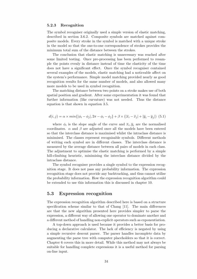
5.2.3 Recognition
The symbol recogniser originally used a simple version of elastic matching,described in section 3.6.2. Composite symbols are matched against com-posite models. Every stroke in the symbol is matched with a unique strokein the model so that the one-to-one correspondence of strokes provides theminimum total sum of the distance between the strokes.
The conclusion that elastic matching is unnecessary was reached aftersome limited testing. Once pre-processing has been performed to resam-ple the points evenly in distance instead of time the elasticity of the timedoes not have a significant effect. Once the symbol recogniser containedseveral examples of the models, elastic matching had a noticeable affect onthe system’s performance. Simple model matching provided nearly as goodrecognition results for the same number of models, and also allowed manymore models to be used in symbol recognition.
The matching distance between two points on a stroke makes use of bothspatial position and gradient. After some experimentation it was found thatfurther information (like curvature) was not needed. Thus the distanceequation is that shown in equation 3.5.
d(i, j) = α×min{|φi − φj |, 2π− φi − φj}+ β × (|xi − xj |+ |yi − yj |) (5.1)
where φi is the slope angle of the curve and xi, yi are the normalisedcoordinates. α and β are adjusted once all the models have been enteredso that the interclass distance is maximised whilst the intraclass distance isminimised. The classes represent recognisable symbols. Different methodsof writing each symbol are in different classes. The interclass distance ismeasured by the average distance between all pairs of models in each class.The adjustment to optimise the elastic matching is performed by a simplehill-climbing heuristic, minimising the interclass distance divided by theintraclass distance.
The symbol recogniser provides a single symbol to the expression recog-nition stage. It does not pass any probability information. The expressionrecognition stage does not provide any backtracking, and thus cannot utilisethe probability information. How the expression recognition algorithm couldbe extended to use this information this is discussed in chapter 10.
5.3 Expression recognition
The expression recognition algorithm described here is based on a structurespecification scheme similar to that of Chang [11]. The main differencesare that the new algorithm presented here provides simpler to parse theexpression, a different way of allowing one operator to dominate another anda different method of handling non-explicit operators such as exponentiation.
A top-down approach is used because it provides a better basis for pro-ducing a declarative calculator. The lack of efficiency is negated by usinga simple recursive descent parser. The parser handles incomplete data byaugmenting the parse tree with computer placeholders so that it is correct.Chapter 6 covers this in more detail. While this method may not always besuitable for handling complete expressions it is a useful method for parsingon-line input.
34
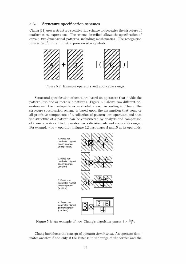
5.3.1 Structure specification schemes
Chang [11] uses a structure specification scheme to recognise the structure ofmathematical expressions. The scheme described allows the specification ofcertain two-dimensional patterns, including mathematics. The recognitiontime is O(n2) for an input expression of n symbols.
+ BA )C(
Figure 5.2: Example operators and applicable ranges.
Structural specification schemes are based on operators that divide thepattern into one or more sub-patterns. Figure 5.2 shows two different op-erators and their sub-patterns as shaded areas. According to Chang, thestructure specification scheme is based upon the assumption that some orall primitive components of a collection of patterns are operators and thatthe structure of a pattern can be constructed by analysis and comparisonof these operators. Each operator has a division rule and applicable ranges.For example, the + operator in figure 5.2 has ranges A and B as its operands.
1. Parse non-dominated highest priority operator (multiplication)
3. Parse non-dominated highest priority operator (addition)
4. Parse non-dominated highest priority operator (numbers)
2. Parse non-dominated highest priority operator (division)
Figure 5.3: An example of how Chang’s algorithm parses 3× 2+64 .
Chang introduces the concept of operator domination. An operator dom-inates another if and only if the latter is in the range of the former and the
35

converse is false. Therefore ‘+’ dominates ‘—’ in the pattern a+ bc , whereas
‘—’ dominates ‘+’ in the pattern a+bc . Thus a combination of dominance
and precedence can be used to define an ordering relation on the operators.Any non-dominated operator has precedence over a dominated one.
5.3.2 The new algorithm
The algorithm is implemented as recursive descent parser. Operator prece-dence implicit in the order that the recursive descent parser attempts them.Either an operator is found and the pattern split into the appropriate sub-patterns, or the parser attempt to find the next operator. In this new al-gorithm, each operator totally divides the pattern. Chang’s algorithm whoexcludes the area vertically overlapping operator from the sub-patterns (seefigure 5.2).
The new algorithm pre-parses the sub-patterns of dominating operators,in order to correctly prioritise dominated operators. Chang uses a more com-plex notion of domination in order to correctly prioritise operators withoutpre-parsing. Chang’s method, while more powerful, requires a more com-plex parsing strategy. Pre-parsing allows a simpler, recursive descent parserto be used. Unlike Chang’s method the new algorithm does not need toprioritise and keep track of operators and sub-patterns in a queue.
Pre-parsing takes a non-dominated dominating operator and parses itssub-patterns before the recursive descent starts. For example, a division op-erator parses its numerator and denominator first, stopping the numeratoror denominator from being parsed in the normal recursive descent. Only op-erators that make use of the two dimensional nature of expressions dominateothers. The two implemented operators that dominate others are divisionand exponentiation.
Figure 5.4 shows how the algorithm parses 3× 2+64 . First the dominated
sub-patterns are fully parsed (2 + 6 and 4), then the algorithm performs anormal recursive descent, parsing first the multiplication and then the divi-sion. The recursive descent priority ordering for this equation is: division,addition, multiplication, numbers. The division parses its two dominatedsub-patterns, then reparses the complete pattern containing the division.Compare this with figure 5.3, that shows Chang’s method which has tomaintain a queue of operators.
Division is handled easily in this manner because the syntax definesthe range of the operands or sub-patterns explicitly. Thus division can becomputed first before the rest of the expression is parsed. Unfortunatelyexponentiation cannot be considered in this way. Although the exponentis explicitly defined by the baseline structure of the expression, the base isnot.
5.3.3 Exponentiation
Exponentiation causes more problems for syntax directed parsing than forother methods such as graph rewriting. This is because there is no explicitsyntax to be directed by, so the top-down parser struggles to extract powersin order to handle them first. Chang attempts to solve this problem by lim-iting the area in which powers can be written. His two-dimensional divisionrule can be seen in figure 5.5. However, completely structural approaches
36

1. Pre-parse divisor sub-patterns first
2. Parse sub-patterns 2+6 and 4
3. Parse whole expression
3. Parse multiplication
3. Correctly parsed expression
Figure 5.4: An example of how the new algorithm parses 3× 2+64 .
such as Chang’s, fail. The rules assumes that only whole syntactic units areparsed and not numbers composed of multiple digits. Chang’s pure struc-tural specification scheme is incapable of parsing 1
2
2 or 123. To solve thisproblem the baseline structure is used in a bottom-up method similar tothat described by Zanibbi et al. [44].
N
NE
Figure 5.5: Chang’s [11] division rule for exponentiation.
Exponentiation is best parsed bottom-up. 212 can be understood cor-
rectly only after the fraction has been parsed and its baseline determined.The recursive descent is in order of mathematical priority, but the pre-parsing is in syntactic order. Thus divisions have a higher syntactic prioritythan exponentiation, and are pre-parsed first. The pre-parser is essentiallya bottom-up syntactic parser.
Exponentiation is parsed in two stages: a pre-parsing of the exponent,and later the actual exponentiation. Whilst this is awkward, it fits simplyinto the structure of the recursive descent parser.
Pre-parsing is done by grouping symbols by baseline into a tree struc-ture. Each exponentiation level is recursively parsed. Figure 5.6 shows the
37
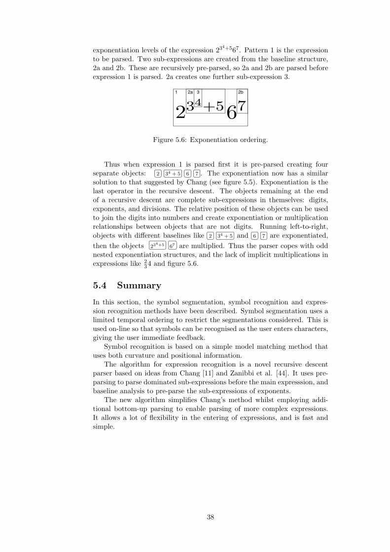
exponentiation levels of the expression 234+567. Pattern 1 is the expressionto be parsed. Two sub-expressions are created from the baseline structure,2a and 2b. These are recursively pre-parsed, so 2a and 2b are parsed beforeexpression 1 is parsed. 2a creates one further sub-expression 3.
normal recursive descent parsing first the multiplication and then the divi-sion. The recursive descent priority ordering for this equation is: division,addition, multiplication then numbers. The division parses its two dom-inated sub-patterns then reparses the whole pattern the division is from.Compare this with figure 5.2, which shows Chang’s method which has tokeep a queue of operators.
Division can be handled easily in this manner because the syntax definesthe range of the operands or sub-patterns explicitly. Thus division can becomputed first before the rest of the expression is parsed. Unfortunatelyexponentiation does not, the exponent is explicitly defined by the baselinestructure of the expression but the base is not.
5.3.3 Exponentiation
Exponentiation causes more problems for syntax directed parsing than forother methods such as graph rewriting. This is because there is no explicitsyntax to be directed by, the top-down parser struggles to determine powerswhich need to be handled first. Chang attempts this problem by limitingthe area in which powers can be written, his two-dimensional division rulecan be seen in figure 5.4. However A completely structural approach suchas Chang’s fails. This rules assumes that numbers are whole syntactic unitsand not composed of multiple digits. A similar rule to deal with multipledigits would have a third sub-pattern centrally aligned to concatenate digits.Chang’s pure structural specification scheme is incapable of parsing 1
22 or
123. To solve this problem I make use of the baseline structure in a bottomup method similar to the one described by Zanibbi et al. in [35].
N
N
E
Figure 5.4: Chang’s [15] division rule for exponentiation.
Exponentiation is best parsed bottom-up, 212 can be understood correctly
only after the fraction is first parsed and its baseline determined. The waythe recursive descent parser is built the recursive descent is not in order ofmathematical priority it is instead in syntactic order. Thus divisions aresyntactically a higher priority than exponentiation. The pre-parsing can bethought of as a bottom up syntactic parser.
Exponentiation is done in these two stages, a pre-parsing of the exponentand later the actual exponentiation. Whilst this is awkward it fits into therecursive descent parser simply.
The pre-parsing is done by grouping the symbols by baseline into a treelike structure. Each exponentiation level is recursively parsed.
234+5 × 67 (5.1)
First the explicit grouping provided by the higher baseline is calculatedthen after the majority of the recursive descent is complete, when the baseof the exponentiation has been calculated the exponentiation is computed.
37
normal recursive descent parsing first the multiplication and then the divi-sion. The recursive descent priority ordering for this equation is: division,addition, multiplication then numbers. The division parses its two dom-inated sub-patterns then reparses the whole pattern the division is from.Compare this with figure 5.2, which shows Chang’s method which has tokeep a queue of operators.
Division can be handled easily in this manner because the syntax definesthe range of the operands or sub-patterns explicitly. Thus division can becomputed first before the rest of the expression is parsed. Unfortunatelyexponentiation does not, the exponent is explicitly defined by the baselinestructure of the expression but the base is not.
5.3.3 Exponentiation
Exponentiation causes more problems for syntax directed parsing than forother methods such as graph rewriting. This is because there is no explicitsyntax to be directed by, the top-down parser struggles to determine powerswhich need to be handled first. Chang attempts this problem by limitingthe area in which powers can be written, his two-dimensional division rulecan be seen in figure 5.4. However A completely structural approach suchas Chang’s fails. This rules assumes that numbers are whole syntactic unitsand not composed of multiple digits. A similar rule to deal with multipledigits would have a third sub-pattern centrally aligned to concatenate digits.Chang’s pure structural specification scheme is incapable of parsing 1
22 or
123. To solve this problem I make use of the baseline structure in a bottomup method similar to the one described by Zanibbi et al. in [35].
N
N
E
Figure 5.4: Chang’s [15] division rule for exponentiation.
Exponentiation is best parsed bottom-up, 212 can be understood correctly
only after the fraction is first parsed and its baseline determined. The waythe recursive descent parser is built the recursive descent is not in order ofmathematical priority it is instead in syntactic order. Thus divisions aresyntactically a higher priority than exponentiation. The pre-parsing can bethought of as a bottom up syntactic parser.
Exponentiation is done in these two stages, a pre-parsing of the exponentand later the actual exponentiation. Whilst this is awkward it fits into therecursive descent parser simply.
The pre-parsing is done by grouping the symbols by baseline into a treelike structure. Each exponentiation level is recursively parsed.
234+5 × 6 (5.1)
First the explicit grouping provided by the higher baseline is calculatedthen after the majority of the recursive descent is complete, when the baseof the exponentiation has been calculated the exponentiation is computed.
37
1 2a 3 2b
Figure 5.6: Exponentiation ordering.
Thus when expression 1 is parsed first it is pre-parsed creating fourseparate objects:
� �2� �� �
34 + 5� �� �6� �� �
7� �. The exponentiation now has a similarsolution to that suggested by Chang (see figure 5.5). Exponentiation is thelast operator in the recursive descent. The objects remaining at the endof a recursive descent are complete sub-expressions in themselves: digits,exponents, and divisions. The relative position of these objects can be usedto join the digits into numbers and create exponentiation or multiplicationrelationships between objects that are not digits. Running left-to-right,objects with different baselines like
� �2� �� �
34 + 5� �and� �6� �� �
7� �are exponentiated,then the objects
� �234+5� �� �
67� �are multiplied. Thus the parser copes with oddnested exponentiation structures, and the lack of implicit multiplications inexpressions like 2
34 and figure 5.6.
5.4 Summary
In this section, the symbol segmentation, symbol recognition and expres-sion recognition methods have been described. Symbol segmentation uses alimited temporal ordering to restrict the segmentations considered. This isused on-line so that symbols can be recognised as the user enters characters,giving the user immediate feedback.
Symbol recognition is based on a simple model matching method thatuses both curvature and positional information.
The algorithm for expression recognition is a novel recursive descentparser based on ideas from Chang [11] and Zanibbi et al. [44]. It uses pre-parsing to parse dominated sub-expressions before the main expresssion, andbaseline analysis to pre-parse the sub-expressions of exponents.
The new algorithm simplifies Chang’s method whilst employing addi-tional bottom-up parsing to enable parsing of more complex expressions.It allows a lot of flexibility in the entering of expressions, and is fast andsimple.
38

Chapter 6
Calculation
Brief Article
The Author
April 1, 2004
23 + 4√9
= 6 (1)
1
4. Calculation
Brief Article
The Author
April 1, 2004
23 + 4√9
= 6 (1)
1
3.
Figure 6.1: Answer calculation.
The majority of current research on expression recognition has been directedtowards that of expression entry, although there have been attempts tomarry expression entry with calculation (for example, the PenCalc project[40]). None of the existing implementations or publications have attemptedto use expression recognition as a user interface for a calculator. The waycalculation works affects the method of interaction.
Few people have properly considered how to build an intuitive calcula-tor, with the notable exception of [50]. This brief chapter covers the waysin which current calculators work their problems and how these might beinterfaced with online handwriting. The calculator used in this thesis ispresented and how it could work for online handwritting is briefly discussed.Further discussion of the user interface is presented in chapter 7.
+
!
–
÷
2
3
1
…1
Enforced artificial parse tree.Figure 6.2: A simple parse tree.
39

6.1 Simple calculators
A simple handheld calculator only operates on two numbers at once. Anyexpression has to be written out so that its binary parse tree is as deepas possible (see figure 6.2). Such calculators are easy to program but anightmare to use! For example, the simple expression (1 + 2) ∗ (3 + 4) hasto use the parse tree in Figure-6.3
This is obviously not an intuitive user interface, and yet it is used by themajority of small handheld calculators use, and is probably what childrenare given as their first calculator. This is an unusable interface for a two-dimensional hand-written calculator.
×
+
43
+
21
×
+
4
MR
3
M
+
21
Natural parse tree. Artificial simple parse tree.
Figure 6.3: A simple but nasty calculation.
6.2 Useable calculators
The vast majority of more complex handheld and simple computer calcula-tors allow some form of linear entry would allow the above example to beentered as (1+2)∗(3+4). These are actually useful calculators. Some allowyou to edit the expression; others like the Sharp EL-531VH, don’t.Frege was the first to
devise an axiomatisationof propositional logic andof predicate logic, andthe first major proponentof logicism... until KurtGodel showed it was im-possible.
Yet the design of these calculators has still not been thought through.Often features are ‘tacked on’ as extras and are neither integrated nor fullythought through. They ignore explicit mathematical rules, such as refer-ential transparency. Referential transparency, set out by Gottlob Frege in1884, provides a clear idea of how variables should be treated. In essence,names always mean the same thing. Thus in a + a = 20, both occurrencesof the letter a should mean the same thing (in this case 10). Furthermore,expressions should behave like the numbers they represent. The Sharp calcu-lator’s different treatment of π, memories, numbers and values like (2+2%),is an example of referential opacity, simply bad mathematics.
Thimbleby [50, 51] provides even more examples and further damningcriticism of how calculators are designed and built.
6.3 Symbolic calculators
Software packages such as Mathematica and Maple, and to a lesser extenthand-held calculators like the Texas Instruments’ TI-89, are examples of
40
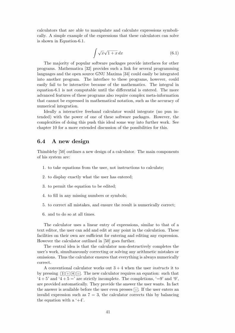
calculators that are able to manipulate and calculate expressions symboli-cally. A simple example of the expressions that these calculators can solveis shown in Equation-6.1. ∫ √
x√
1 + x dx (6.1)
The majority of popular software packages provide interfaces for otherprograms. Mathematica [32] provides such a link for several programminglanguages and the open source GNU Maxima [34] could easily be integratedinto another program. The interface to these programs, however, couldeasily fail to be interactive because of the mathematics. The integral inequation-6.1 is not computable until the differential is entered. The moreadvanced features of these programs also require complex meta-informationthat cannot be expressed in mathematical notation, such as the accuracy ofnumerical integration.
Ideally a interactive freehand calculator would integrate (no pun in-tended) with the power of one of these software packages. However, thecomplexities of doing this push this ideal some way into further work. Seechapter 10 for a more extended discussion of the possibilities for this.
6.4 A new design
Thimbleby [50] outlines a new design of a calculator. The main componentsof his system are:
1. to take equations from the user, not instructions to calculate;
2. to display exactly what the user has entered;
3. to permit the equation to be edited;
4. to fill in any missing numbers or symbols;
5. to correct all mistakes, and ensure the result is numerically correct;
6. and to do so at all times.
The calculator uses a linear entry of expressions, similar to that of atext editor, the user can add and edit at any point in the calculation. Thesefacilities on their own are sufficient for entering and editing any expression.However the calculator outlined in [50] goes further.
The central idea is that the calculator non-destructively completes theuser’s work, simultaneously correcting or solving any arithmetic mistakes oromissions. Thus the calculator ensures that everything is always numericallycorrect.
A conventional calculator works out 3 + 4 when the user instructs it toby pressing
� �3� �� �
+� �� �4� �� �
=� �. The new calculator requires an equation: such that‘4 + 5’ and ‘4 + 5 =’ are strictly incomplete. The completions, ‘=9’ and ‘9’,are provided automatically. They provide the answer the user wants. In factthe answer is available before the user even presses
� �=� �. If the user enters an
invalid expression such as 7 = 3, the calculator corrects this by balancingthe equation with a ‘+4’.
41
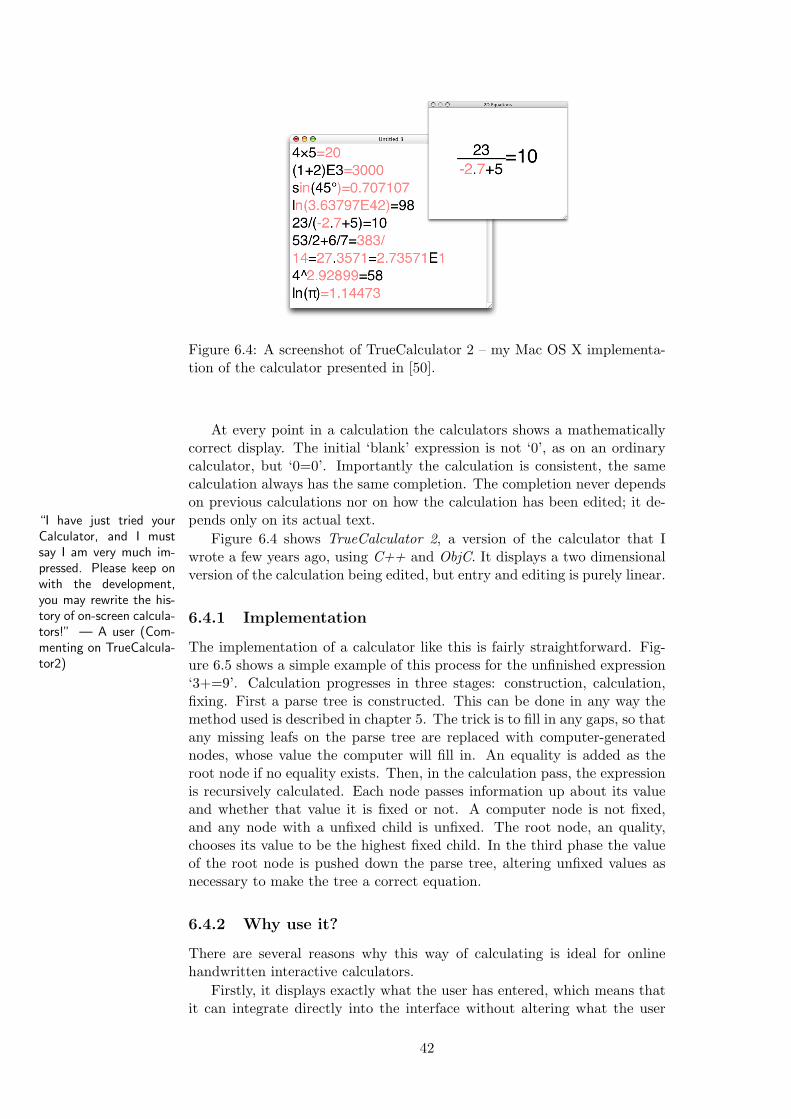
Figure 6.4: A screenshot of TrueCalculator 2 – my Mac OS X implementa-tion of the calculator presented in [50].
At every point in a calculation the calculators shows a mathematicallycorrect display. The initial ‘blank’ expression is not ‘0’, as on an ordinarycalculator, but ‘0=0’. Importantly the calculation is consistent, the samecalculation always has the same completion. The completion never dependson previous calculations nor on how the calculation has been edited; it de-pends only on its actual text.“I have just tried your
Calculator, and I mustsay I am very much im-pressed. Please keep onwith the development,you may rewrite the his-tory of on-screen calcula-tors!” — A user (Com-menting on TrueCalcula-tor2)
Figure 6.4 shows TrueCalculator 2, a version of the calculator that Iwrote a few years ago, using C++ and ObjC. It displays a two dimensionalversion of the calculation being edited, but entry and editing is purely linear.
6.4.1 Implementation
The implementation of a calculator like this is fairly straightforward. Fig-ure 6.5 shows a simple example of this process for the unfinished expression‘3+=9’. Calculation progresses in three stages: construction, calculation,fixing. First a parse tree is constructed. This can be done in any way themethod used is described in chapter 5. The trick is to fill in any gaps, so thatany missing leafs on the parse tree are replaced with computer-generatednodes, whose value the computer will fill in. An equality is added as theroot node if no equality exists. Then, in the calculation pass, the expressionis recursively calculated. Each node passes information up about its valueand whether that value it is fixed or not. A computer node is not fixed,and any node with a unfixed child is unfixed. The root node, an quality,chooses its value to be the highest fixed child. In the third phase the valueof the root node is pushed down the parse tree, altering unfixed values asnecessary to make the tree a correct equation.
6.4.2 Why use it?
There are several reasons why this way of calculating is ideal for onlinehandwritten interactive calculators.
Firstly, it displays exactly what the user has entered, which means thatit can integrate directly into the interface without altering what the user
42
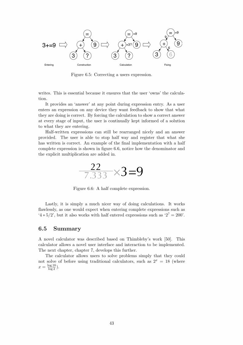
=
+
?
9
3
=
+
?
9
3
=3?
=9
3+=9
=
+
6
9
3
9
6
=9
Construction Calculation FixingEntering
Figure 6.5: Correcting a users expression.
writes. This is essential because it ensures that the user ‘owns’ the calcula-tion.
It provides an ‘answer’ at any point during expression entry. As a userenters an expression on any device they want feedback to show that whatthey are doing is correct. By forcing the calculation to show a correct answerat every stage of input, the user is continually kept informed of a solutionto what they are entering.
Half-written expressions can still be rearranged nicely and an answerprovided. The user is able to stop half way and register that what shehas written is correct. An example of the final implementation with a halfcomplete expression is shown in figure 6.6, notice how the denominator andthe explicit multiplication are added in.
Figure 6.6: A half complete expression.
Lastly, it is simply a much nicer way of doing calculations. It worksflawlessly, as one would expect when entering complete expressions such as‘4 ∗ 5/2’, but it also works with half entered expressions such as ‘2? = 200’.
6.5 Summary
A novel calculator was described based on Thimbleby’s work [50]. Thiscalculator allows a novel user interface and interaction to be implemented.The next chapter, chapter 7, develops this further.
The calculator allows users to solve problems simply that they couldnot solve of before using traditional calculators, such as 2x = 18 (wherex = log 18
log 2 ).
43
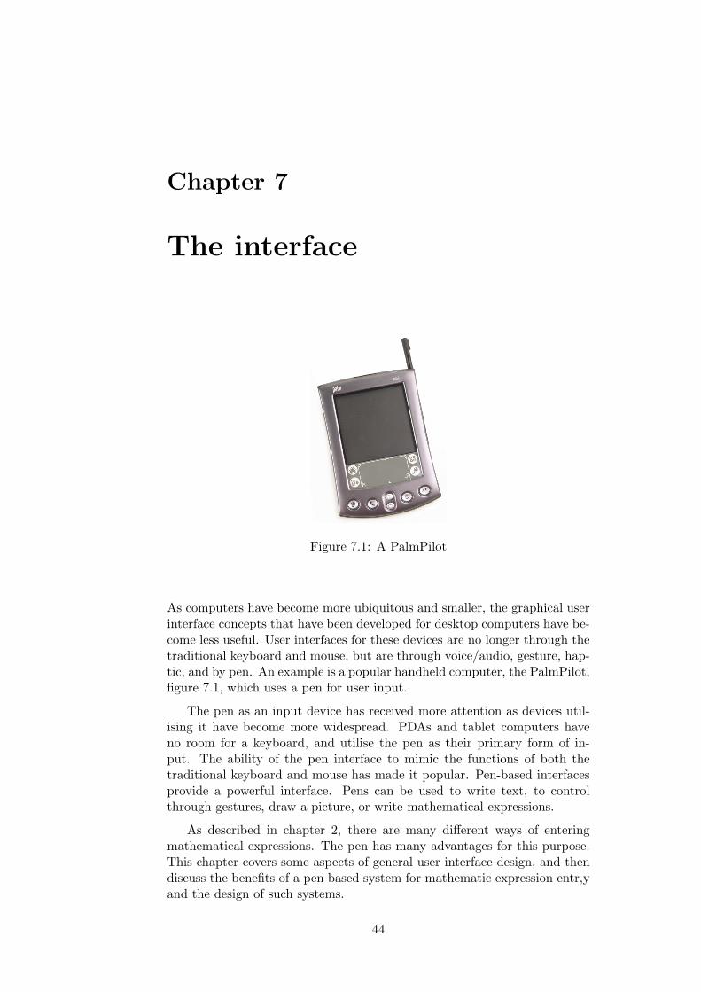
Chapter 7
The interface
Figure 7.1: A PalmPilot
As computers have become more ubiquitous and smaller, the graphical userinterface concepts that have been developed for desktop computers have be-come less useful. User interfaces for these devices are no longer through thetraditional keyboard and mouse, but are through voice/audio, gesture, hap-tic, and by pen. An example is a popular handheld computer, the PalmPilot,figure 7.1, which uses a pen for user input.
The pen as an input device has received more attention as devices util-ising it have become more widespread. PDAs and tablet computers haveno room for a keyboard, and utilise the pen as their primary form of in-put. The ability of the pen interface to mimic the functions of both thetraditional keyboard and mouse has made it popular. Pen-based interfacesprovide a powerful interface. Pens can be used to write text, to controlthrough gestures, draw a picture, or write mathematical expressions.
As described in chapter 2, there are many different ways of enteringmathematical expressions. The pen has many advantages for this purpose.This chapter covers some aspects of general user interface design, and thendiscuss the benefits of a pen based system for mathematic expression entr,yand the design of such systems.
44

7.1 User interface design
The user interface is an essential part of any system. A good user interfaceenables a user to understand what is happening and enables them to makethe computer do what they want. A major part of the motivation for thisthesis is the present array of bad, awkward and cumbersome user interfaces,used to enter mathematical expressions and to get answers. Problems withthe current user interfaces were highlighted in chapter 6.
Usability has always been area of research in computer science. Eversince computers were cogs and wheels, people have been struggling to makethem ever more usable. With the invention of graphical user interfaces over30 years ago, user interface design became an area of mainstream research.Unsurprisingly, there is a wide body of literature concerning the good designof user interfaces, [14, 24, 46]. Many people have provided user interfaceguidelines that dictate how a good user interface should work. Highlighthere are some of the concepts that good user interfaces should be based on.These guidelines are neither comprehensive nor commandments, but theyprovide an understanding of some of the more important design problemsand solutions.
Visibility of system status: The system should always keep the user in-formed about what is going on, providing appropriate timely feedback.Changes in behavior should be reflected in the appearance of the pro-gram.
Symmetry: Symmetry with the real world and other programs. The in-terface should be logically consistent with interfaces that the user isalready used to.
Consistency and standards: Users should never have to think about wh-ether different words, situations, or actions mean the same thing. Like-wise follow platform guidelines.
Error recovery: Help users recognise, diagnose, and recover from errors.Errors should be precise, indicating the problem and constructivelysuggesting a solution.
Undo: To this effect support undo and redo, allowing recovery from mis-takes. Permanent actions should be clearly marked.
Modeless interfaces: Limit user activity to one well-defined context un-less there is a good reason not to. Do not change the rules of the gamewithout clear indication.
Feature exposure: Let the user see clearly what functions are available.Provide no hidden methods or shortcuts.
Help: Provide help and documentation. No matter how intuitive a system,a user will always need some help.
Aesthetics: Aesthetic minimalist design. Do not clutter the interface withirrelevant information.
Section 7.5 outlines how these guidelines are used in the design of myprototype.
45

7.2 Pen based user interfaces
Compared to the literature on general user interface design there is surpris-ingly little related to pen-based user interfaces. Many papers have beenpublished on handwriting recognition, very few have been written regard-ing pen based interfaces. PenPoint [9] is one of the few complete systemsdescribed. Research on specific areas of pen based interfaces has been con-ducted, notably text entry, editing, and the use of special gestures to controladditional functions.
Meyer [35] gives a good detailed overview of the whole technology, in-cluding both a history of pen based computing and more technical aspectsof the hardware and software.
A pen is different from a mouse. It provides better and finer control (trywriting your signature with a mouse). Whilst it is easy to manipulate threeor more buttons on a mouse, it is difficult to hold a pen and press buttonson the barrel.
7.2.1 Advantages
The major advantage of a pen-based system is the symmetry of the interface.The majority of users are already competent at writing with a pen. Thisadvantage is especially prevalent with mathematical expressions, becausethe majority of mathematical work is still done on paper with a pen orpencil. Using a pen based system to enter expressions means that anyonecan use it with little or no training.There need be no restrictions on how anequation is written. Ideally if a mathematician writes an equation neatly inexactly the same way as they would on paper, it can be recognised.
The other main advantage is there is no need for any other interface.Pens can replicate the complete functionality of both keyboard and mouse.There is no need switch mode, the pen can be used for both.
7.3 Pen based expression entry
Any pen-based expression entry system should support certain features thatmake the interface easy to use and flexible. Several of these are covered inthe next few sub-sections.
7.3.1 Sketching
Ideally a user could draw rough sketches in the same way in a computersystem. Often when solving a problem a user will not jump straight ontoher computer and solve it. First she will do some rough working, drawdiagrams, record measurements, or jot down formulae. This process helpsthe user to get a feel for the problem, aiding the derivation of its solution.
The system should behave exactly like a sheet of paper, allowing a userto doodle and sketch away. Unfortunately, this is virtually impossible. Au-tomatically detecting the difference between sketches and equations is veryhard. One solution would be to specify areas in which mathematical expres-sions are parsed and others where you can draw.
46

7.3.2 Expressions
The system should allow the user to enter expressions as they would onpaper, without unnatural restrictions. For example, the user should notbe forced to enter the expression in a linear fashion as some expressionrecognition methods require [27].
The restrictions imposed by this system the small timing constraints,and the requirement for contiguous symbols to be written in one go, are notintrusive so the user does not have to alter their way of writing overly much.
7.3.3 Editing
It should be possible to edit expressions. Both input and output expressions(that is, an expression just entered, and one that has been computed) shouldbe treated in the same manner. The system should allow high-level editing,such as rearranging. Insertion and deletion should be possible at any point inthe expression. Moving and rearranging sub-expressions and the expressionas a whole should be supported.
Ideally, the user is able to perform editing functions such as insert, delete,cut, and paste. To implement this with a pen based interface, withoutleaving the paradigm, requires special gestures that are assigned to each ofthe editing functions. For example, a scribble could be used for deletion, acaret for insertion at a point, and circling for selection. This allows the userto perform all input and editing operations using the pen without resortingto special menus, buttons, or a keyboard.
Character editing is different from expression editing. Character editinginvolves correcting the computers guess at the semantics of a set of strokes.Expression editing is more complex, involving moving copying and changingsub-expressions.
Character editing
Character of symbol editing should ideally be a non-issue, but unfortunatelyit is. Character editing can be achieved simply by a pop-up menu that allowsyou to select a correct symbol. However pop-up menus are awkward withpen based user interfaces, and [19] introduces the idea of tap correcting asymbol. This works by displaying underneath each symbol alternatives thatyou can select by tapping on them.
Expression editing
The basis of most editing functions is the ability to select parts of the expres-sion to manipulate. One method of doing this that is suited to pen-basedinterfaces is to allow the user to circle the intended part or subexpression.Rearranging can then be achieved by dragging, deletion and duplication canbe accomplished through gestures.
7.3.4 Gestures
A gesture is a written command specified by a single stroke of the pen. Theyare fast and iconic, which makes them easier to remember [37].
The user should be able to interact through the use of natural gesturesrather than buttons or other interface concepts that leave the pen and paper
47

paradigm. Any special functions, such as deletion or undo, should havenatural gestures associated with them. In the case of deletion, the usercould scribble over the symbols to be removed. This allows the user toperform all operations using the pen, without having to revert to keyboardor mouse.
Figure 7.2: The undo gesture from Mac OS X.
Gestures are relatively underused by users [1]. The reasons for not usinggestures are two-fold: either users did not know the gesture existed (or hadforgotten), or the user hesitated to use the gesture because the computernormally misrecognised it.
7.4 Feedback
The first user interface guideline from section 7.1 was “Visibility of systemstatus”. Providing good feedback is a well recognised requirement.
7.4.1 Annotation
For providing character feedback different methods have been used such as:annotating the written strokes with a small character, and altering the colouror style of the strokes [47]. These methods have several disadvantages. Oftenthe annotation is not clear, it is usually quite small, and changing colour orstyle is a subtle effect without clear meaning. Littin [27] used a vector fontthat replaced the strokes.
7.4.2 Morphing
Littin [27] suggested morphing as a suitable method for retaining continuitybetween an entered expression and a recognised expression. He describes amethod that replaces the stroke data with a vector font similar to handwrit-ing which is then morphed to the correct place.
Zanibbi et al. [42] describe a different method of “style preserving morphs”in which the user’s stroke data is morphed to a appropriate size and location.An example of such a morph is shown in figure 7.3.
Their claim is that style-preseving morphs provide a better form of feed-back than typeset symbols, because users prefer rough-looking sketches; andtypeset input connotes an undesired authority and immutability.
The benefits of morphing are clear. They minimise the disruption of theuser’s mental map. By using gradual changes, the user can easily keep trackof what is happening. Morphing provides useful feedback on the accuracyof the ongoing interpretation.
48

a. Original input b. After style-preserving morph
Figure 2: The effect of a Style-Preserving Morph.
ten obvious, for example in Figure 3, where the super-scripted “2” has been interpreted as being adjacent to the“x”. Once these types of errors are identified, they areeasy to fix using operations built into FFES.In addition to increasing consistency, the resizing
of symbols also provides a small amount of feedbackon character recognition: if a handwritten symbol issquashed or stretched into an unexpected shape, it is asure sign of a recognition error. For example, in Figure 3,the lower-case “x” has clearly been mis-recognized.The new bounding boxes for symbols after the morph
are computed bottom-up from the baseline structure treereturned by DRACULAE, proceeding from leaf baselinesto the baseline below the EXPRESSION node at the rootof the tree.The procedure for formatting the bounding boxes of
each baseline is as follows:
1. An average of the height of the baseline symbols iscomputed, where each symbol height is weightedbased on identity. For example, the height of alower-case letter such as “x” is doubled. Flat sym-bols such as horizontal lines are not included in theaverage. Average height and typeset symbol aspectratios are then used to recompute the bounding boxsizes.
2. Baseline symbols are vertically aligned and any sub-expressions nested vertically relative to a symbol(e.g. superscripted, below) are placed 15 pixelsabove/below the parent symbol.
3. Horizontal spacing is cleaned up: first subexpres-sions which are nested above or below baseline sym-
a. Original input b. After style-preserving morph
Figure 3: Interpretation errors become clear.
bols are centered, and super and subscripted subex-pressions are spaced at a fixed distance of 15 pixelsto the right of their parent symbol. Then an aver-age of the baseline symbol widths is computed (thinsymbols such as ’i’ are not included in the average),and the larger of 15 pixels and 1/3 the average widthis placed between the areas filled by each baselinesymbol and its nested subexpressions.
The Align operation must preserve the semantics, whichimplies that aligning input should not alter baseline struc-ture. Ensuring that DRACULAEwould produce the samebaseline structure tree before and after using Align wasone of the key design constraints for the formatting algo-rithm.The formatting algorithm executes in under a second
on a 200MHz machine. Once it is complete we have atarget bounding box for each of the user-drawn symbols.The source and target bounding boxes are used to define ageometric transformation comprised of a translation anda scale that will achieve the desired effect. The trans-formation is divided into equal steps that are applied insequence to produce a morphing effect. We implementedthe morph in Tcl/Tk. It is achieved in fifteen frames, dis-played at approximately ten frames a second. In compar-ison, a typeset representation can be generated and dis-played in under a second.
5 ExperimentOur enhanced version of the equation editor could pro-vide feedback in terms of a conventional Render opera-tion (resulting in a typeset formula being displayed as abitmap in a separate window) or an Align operation (re-sulting in a style-preserving morph on the user’s drawingcanvas). In an attempt to isolate the effect of the style-preserving morph, we designed an experiment to com-pare the performance of FFES under three conditions ofavailable feedback:
1. conventional Render operation but no Align opera-tion,
2. Align operation but no Render operation, and
Figure 7.3: A style-preserving morph from [42]
7.5 The design
The system described in this thesis uses a single canvas for mathematicalexpressions. Sketching and drawing are unsupported. The user interface isshown in figure 7.4.
Figure 7.4: The user interface.
The interface is aesthetically simple. Its sole adornment is a reminderof the delete gesture in the bottom right corner. This solves the problem ofusers forgetting gestures. The interface is minimalist and clearly providesclear feature exposure, as specified in the guidelines in section 7.1.
The interface is completely modeless. After testing several different waysof editing expressions, it was found that for the majority of mathematicalexpressions, the easiest way of editing was to delete and rewrite portionsof the expression. This keeps the interface very simple. Allowing draggingor tap correcting creates areas of the screen that function differently fromeach other. By allowing only a simple delete gesture, no mode changes arenecessary. Every part of the screen or virtual paper acts like paper: everyclick and drag draws.
The ‘delete’ gesture is the only editing function. The hypothesise is thatno other editing commands are necessary. It is important to provide somevisual feedback to the user showing them what has changed because it is adestructive expression altering command. This is done by displaying a little‘poof’ animation wherever symbols from the expression are removed. Thisstandard from Mac OS X feedback animation is used to show deletion ofother items in other applications and contexts.
Undo would be a complex operation because the equation is continuously
49

morphed out of shape. An undo has to reset the morph before it can undoany editing operation. Undo was not implemented because of the complexityof the concept and interface for the user.
The visibility of the system’s status is provided through two kinds offeedback when entering expressions: annotation and morphing. As the useris writing, the system can process in the background. As mentioned insection 5, there is a short delay before symbol recognition takes place, toallow for composite disjoint symbols. After this delay, a symbol is recognised.The user is informed of this recognition by visual feedback: the writtenstrokes are replaced by a typeset character that is stretched to the stroke’sbounding box. Figure 7.5 demonstrates the improved clarity of this methodcompared to annotation. The left screenshot is from FFES [47]; the rightscreenshot from the system developed in this thesis.
Zanibbi et al. describe the typesetting of a calculation as a negative,connoting unwanted authority and immutability. For a calculator, this au-thority provided by typeset symbols is essential; a user has to trust ananswer.
Annotated Typeset replaced
Figure 7.5: A comparison of annotation versus replacing for feedback
By providing both explicit annotation (by replacement of symbols) andmorphing of layout, the system provides feedback on exactly what calcula-tion is being computed without disrupting the user’s map of what is hap-pening.
Morphing starts after a short time delay from when the user stop writing,and halts when the user starts writing again. This stops a morph fromdistracting the user and from rearranging expressions whilst they are tryingto enter them.
Morphing adjusts the layout as little as possible, keeping the shape of theexpression as congruent to the user’s writing as possible whilst reformattingit. The morph does two things. First, the average font size of the expressionis enforced over the whole expression. Second, all the symbols are rearrangedinto an appropriate position on the canvas. An example of an expressionbeing morphed is shown in figure 7.6.
The unique calculator described in chapter 6 also provides several veryuseful forms of feedback. It allows morphing to occur before the expressionis finished, and the user is continually kept informed of the solution to whatthey are entering.
Also, because the calculator enforces a mathematically correct expres-sion, parts of the expression (such as a denominator) left unfinished aredisplayed with a computer number in their place. Not only does this pro-vide mathematical feedback to the user (it might be the answer they want),but it also highlights the region or area unfinished.
Computer numbers are always displayed with a distinctly different styleto that of user entered symbols. The default display of such numbers is grey.
50
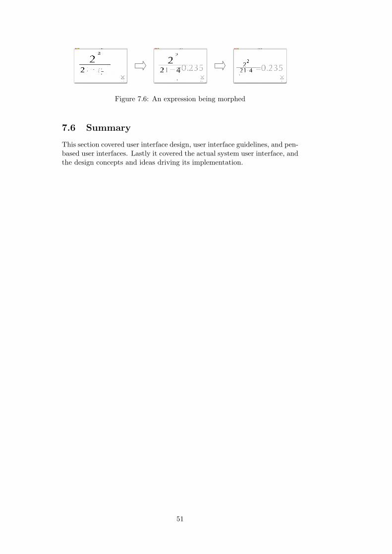
Figure 7.6: An expression being morphed
7.6 Summary
This section covered user interface design, user interface guidelines, and pen-based user interfaces. Lastly it covered the actual system user interface, andthe design concepts and ideas driving its implementation.
51
Chapter 8
Usability testing
In a usability test, a number of people representative of the final intendedusers, use the application, test it, and give feedback.
Usability testing is different to software testing. Software testing is a pro-cess specifically used to identify the correctness, completeness and quality ofdeveloped computer software. Usability testing is a means of measuring howwell people are able to use something for its intended purpose in practice.User testing provides an insight into how people might use a system. Thisinsight is often contrary to the expectations of the developers of the system.
The main purpose in usability testing this system was to evaluate whetherit provides a significant usability improvement over other ways calculationsare performed. The system is successful if some users would prefer to use itover existing calculators like standard handheld calculators.
The testing also provides an opportunity to corroborate or refute theuser interface principles, discussed in the last chapter, and implemented inthe calculating system. These include the morphing feedback, the use of theunique declarative engine and the limited editing facilities. The testing alsocovers the accuracy and timeliness of the systems symbol and expressionrecognition.
8.1 Designing the test
There are a number of different ways to conduct a usability test. Redishand Dumas [21] provide a comprehensive study of the whole area.
The ‘thinking aloud’ protocol is a method used to gather data duringa test by asking real users to think aloud as they are performing a set ofspecified tasks. Similar methods are sometimes used in psychology. Usersare asked to say out-loud whatever they are looking at, thinking, doing andfeeling as they perform a task. This enables observers to see how users reactto and use their product. The observers objectively take notes of everythingthe users say and do. Often the tests are video and audio taped for reference.The advantage of this method is that the researcher can “get inside” theuser’s head and find out what they are thinking. The disadvantage is that“thinking aloud” is often unnatural and awkward for the users.
Paired user testing is different a approach. It attempts to overcome theawkwardness of thinking aloud. In paired user testing, the testing is doneby pairs of users. The users are instructed to discuss what they are thinkingand doing with each other. When a problem occurs, they work through
52

it together. An advantage of this method is that the atmosphere is muchmore natural and relaxed. It can also be argued that the results are morereflective of a real world situation, because users often ask their peers forhelp.
8.1.1 What to measure?
Usability testing generally involves measuring the response of test subjectsin four areas: time on task, accuracy, recall, and emotional response. Threemodified areas was used to test this system:
Time on Task – How long does it take users to complete a set of basictasks? (For example, find the answer to 3× (4 + 5).)
Accuracy – How many mistakes did the symbol or expression recognisermake? (How did the user cope?)
Ease of use – How does the user feel about the tasks completed? (Confi-dent? Stressed? Would the user recommend this system to a friend?)
8.2 Participants
The ideal users for usability testing are those within the system’s targeteddemographic. They will have the same background knowledge and skills ofcomputers and mathematics as expected users.
The target population for this calculator is anyone who owns and makesuse of a calculator. School children, the general public, and mathematiciansare all within the broad intended audience. A number of people were chosenthat could effectively represent this audience.
If there are too few participants the system will not be rigourously tested.However, too many users will require and a lot of extra time to analyse [21].Dummas and Redish suggest that six to twelve participants is appropriate;others such as Nielsen [38] suggest three to five participants.
A total of nine participants took part in the testing, four of whom knewme personally. Three of these had seen the system before testing, and twowere comfortable using a pen and tablet. These users were reflective of thetarget audience, and included the general public, students, and professionals.
8.3 The test
Personal experience has shown that the pen and tablet are initially difficultto use. Before the test began, users were allowed to familiarise themselveswith the pen and tablet. This involved suggesting that they try to writewords and numbers and draw pictures with the user interface. The observerthen gave a short demonstration of the system, running through a samplesum. When the user announced that they were ready, the observer startedthe test by giving the user a list of tasks on a piece of paper, (see figure 8.1).Some of these questions were based on old GCSE mathematics papers.
The thinking aloud protocol was used. Participants undertook severaltasks while an observer (myself) watched them and helped when they wereunable to solve problems. On conclusion of the test, the observer discussed
53

any issues that arose during testing. This was supplemented by an anony-mous questionnaire. The tests were recorded on video and the interactionon screen was recorded.
An anonymous questionnaire has the advantage that participants canfreely express their thoughts about the system without fear of retribution.Having a discussion afterwards allows the questionnaire to ask additionalquestions resulting from issues that arose in the testing.
After discussing the calculating system with the observer, users wereasked to perform the same calculations again on either their own pocketcalculator or the standard one provided (a Sharp EL-531GH D.A.L.). Thesetests were also recorded.
Upon completion of the test, the video recordings were reviewed andinformation on error rates and time on task was extracted and recorded.
• Practice calculations:
– Calculate 3 + 62
– Calculate 7× 4
– Calculate 45
– Calculate 9− = 5
– Calculate 32
– Calculate 3? = 64
• Simple calculations:
– Calculate 2× 3 + 4
– Calculate 22
21−4
– Calculate 9− 2/3
• Mathematical problems:
– What is the average of 21, 34 and 56?
– What multiple of 32 equals 50?
– What power of two is 28?
Figure 8.1: Usability tasks.
61
• Practice calculations:
– Calculate 3 + 62
– Calculate 7× 4
– Calculate 45
– Calculate 9− = 5
– Calculate 32
– Calculate 3? = 64
• Simple calculations:
1. Calculate 2× 3 + 4
2. Calculate 22
21−4
3. Calculate 9− 2/3
• Mathematical problems:
3. What is the average of 21, 34 and 56?
4. What multiple of 32 equals 50?
5. What power of two is 28?
Figure 8.1: Usability tasks.
54
• Practice calculations:
– Calculate 3 + 62
– Calculate 7× 4
– Calculate 45
– Calculate 9− = 5
– Calculate 32
– Calculate 3? = 64
• Simple calculations:
1. Calculate 2× 3 + 4
2. Calculate 22
21−4
3. Calculate 9− 2/3
• Mathematical problems:
4. What is the average of 21, 34 and 56?
5. What multiple of 32 equals 50?
6. What power of two is 28?
Figure 8.1: Usability tasks.
54
Figure 8.1: Usability tasks.
8.4 Summary
The design and structure of the user testing was described. The thinkingaloud protocol was used with nine participants. The tasks the users under-took are shown in figure 8.1. These tests were observed and recorded forlater analysis.
The results of the usability testing are detailed and discussed in the nextchapter, chapter 9.
54

Chapter 9
Evaluation
This chapter reports on the findings of the user testing — overall impression,accuracy, and timings. The user interface is evaluated with respect to theusability criteria in section 8.1.1 and the users responses in the question-naires. The chapter concludes with an overall evaluation of the system anda summary of the positive and negative aspects of the system.
9.1 Statistics
A total of nine participants gives a good indication of the usability of thesystem. However, the statistical results generated from this user testingshould be treated as preliminary. For more statistically valid results, alarger number of participants would be required.
A second more comprehensive test, consisting of more participants shouldbe undertaken to corroborate the preliminary testing presented here.
9.2 Results
Participants found the interface and concepts easy to learn and use. Whenasked to rate the system in terms of ease of use compared to other systemsthey had used, on a scale of 0 (Worse) to 5 (Better), the answers were allabove 3 and had an average of 4.1.
The results presented here were extracted from the video tapes of the usertests and from the questionaires. Comprehensive results from the anony-mous questionnaire, and some verbal questions, are in appendix B. Thissection provides objective results for user testing. The next section assessesand discusses these results.
9.2.1 Time on Task
Figure-9.1 shows the average time for the users to complete each of thetasks in figure 8.1. It shows a comparison in seconds of the time for a userto complete each tasks using this system and using their own calculator.The last two tasks were uncompleted by several users when using a normalcalculator, so these results are averages over the users that completed themsuccessfully.
Participant four had problems with the second task 22
21−4 , they wereunable to work out how to square numbers. When they did they then
55
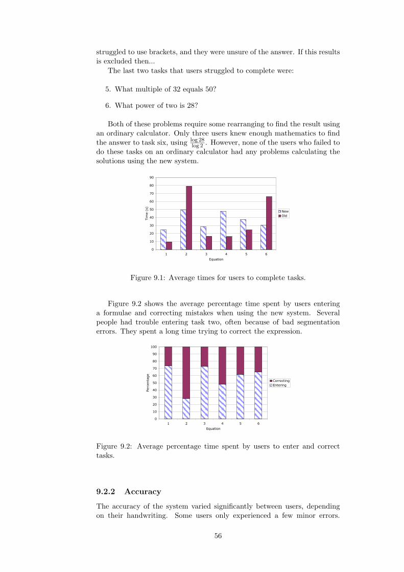
struggled to use brackets, and they were unsure of the answer. If this resultsis excluded then...
The last two tasks that users struggled to complete were:
5. What multiple of 32 equals 50?
6. What power of two is 28?
Both of these problems require some rearranging to find the result usingan ordinary calculator. Only three users knew enough mathematics to findthe answer to task six, using log 28
log 2 . However, none of the users who failed todo these tasks on an ordinary calculator had any problems calculating thesolutions using the new system.
0
10
20
30
40
50
60
70
80
90
1 2 3 4 5 6
Equation
Tim
e (
s)
New
Old
Figure 9.1: Average times for users to complete tasks.
Figure 9.2 shows the average percentage time spent by users enteringa formulae and correcting mistakes when using the new system. Severalpeople had trouble entering task two, often because of bad segmentationerrors. They spent a long time trying to correct the expression.
0
10
20
30
40
50
60
70
80
90
100
1 2 3 4 5 6
Equation
Percentage
Correcting
Entering
Figure 9.2: Average percentage time spent by users to enter and correcttasks.
9.2.2 Accuracy
The accuracy of the system varied significantly between users, dependingon their handwriting. Some users only experienced a few minor errors.
56
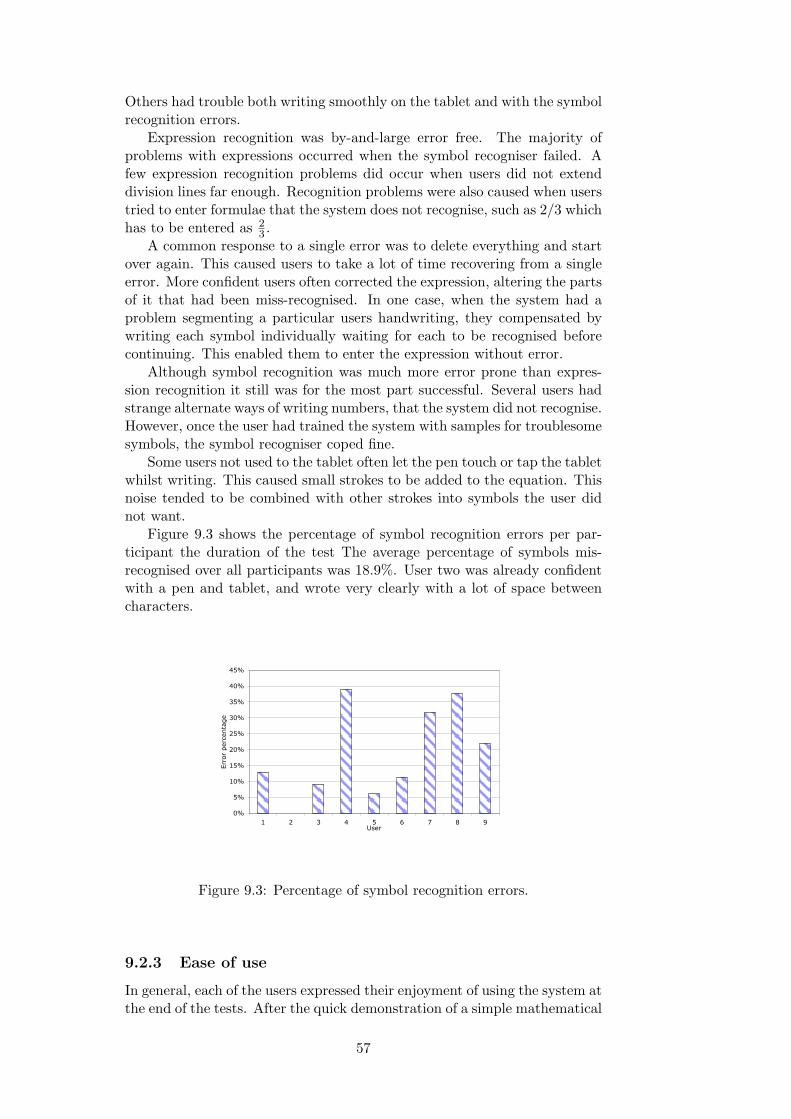
Others had trouble both writing smoothly on the tablet and with the symbolrecognition errors.
Expression recognition was by-and-large error free. The majority ofproblems with expressions occurred when the symbol recogniser failed. Afew expression recognition problems did occur when users did not extenddivision lines far enough. Recognition problems were also caused when userstried to enter formulae that the system does not recognise, such as 2/3 whichhas to be entered as 2
3 .A common response to a single error was to delete everything and start
over again. This caused users to take a lot of time recovering from a singleerror. More confident users often corrected the expression, altering the partsof it that had been miss-recognised. In one case, when the system had aproblem segmenting a particular users handwriting, they compensated bywriting each symbol individually waiting for each to be recognised beforecontinuing. This enabled them to enter the expression without error.
Although symbol recognition was much more error prone than expres-sion recognition it still was for the most part successful. Several users hadstrange alternate ways of writing numbers, that the system did not recognise.However, once the user had trained the system with samples for troublesomesymbols, the symbol recogniser coped fine.
Some users not used to the tablet often let the pen touch or tap the tabletwhilst writing. This caused small strokes to be added to the equation. Thisnoise tended to be combined with other strokes into symbols the user didnot want.
Figure 9.3 shows the percentage of symbol recognition errors per par-ticipant the duration of the test The average percentage of symbols mis-recognised over all participants was 18.9%. User two was already confidentwith a pen and tablet, and wrote very clearly with a lot of space betweencharacters.
0%
5%
10%
15%
20%
25%
30%
35%
40%
45%
1 2 3 4 5 6 7 8 9User
Err
or
per
centa
ge
Figure 9.3: Percentage of symbol recognition errors.
9.2.3 Ease of use
In general, each of the users expressed their enjoyment of using the system atthe end of the tests. After the quick demonstration of a simple mathematical
57

expression, not a single user asked a question regarding the use of the system.Every user found that the system worked as they expected it to.
Feedback from the questionnaires reflects this. Comments were madeby all participants praising the simple and intuitive user interface. Usersliked the lack of buttons and the need not to think about things like extrabrackets.
However, several users also expressed some frustration with the symbolrecognition, especially when the system repeatedly misrecognised certainsymbols. Most users also commented that they the pen and tablet, awkwardto use.
Every user liked the morphing, and they particularly liked the fact thatthey could instantly see what the calculator was calculating. The majorityalso liked the delete gesture, and did not think that the calculator neededfurther methods of editing expressions.
Some users did find that the delete gesture was difficult to use over alarge area, and several suggested the addition of a ‘clear’ button.
9.3 Conclusions
9.3.1 Time on task
For the simpler sums, like 9 − 2/3, a handheld calculator was much fasterthan the new system. This was expected. The majority of users were familiarwith handheld calculators, and had used them over many years.
The new system lags a small amount of time to allow users to entercomposite symbols. A couple of users commented that it was a bit slow.This could easily be remedied by changing the time settings for individualusers.
Encouragingly two of the tasks were actually faster on the new system.They were faster for different reasons. Task two, 22
21−4 , was faster becauseusers could enter it “as they saw it” rather than having to search for buttonson a calculator.
For the last task “What power of two is 28?”, every user was able tocomplete the task on the new system, yet most struggled to solve it ona handheld calculator. Thus this new calculator enables users to performmathematics that they could not do before. It was faster mainly becauseusers did not have to rearrange the expression in their head. This washelpful, even for those who knew the rearrangement.
However, the actual differences in the time taken, are only guidelines.The actual results are not statistically significant.
9.3.2 Accuracy
A large part of the time taken to complete the tasks was taken up with re-covering from symbol recognition errors. There is a fairly strong correlationbetween the percentage of errors and the time taken. Figure 9.4 shows therelationship between these two measurements. The correlation coefficient ishigh, roughly 0.78, but the lack of samples mean that this is not significant.
The accuracy percentage of 81.1% is poor. One in five characters is mis-recognised on average. This significantly lowers the usability of the system.
58

It is clear from figure 9.3 that the symbol recogniser is capable of good recog-nition rates with the right style of handwriting. Once a user has trained thesystem for their handwriting it is possible that much higher recognition rateswill follow.
0
50
100
150
200
250
300
350
400
0% 10% 20% 30% 40% 50%
Percentage of errors
Tota
l tim
e t
aken
Figure 9.4: Total time taken and the percentage of errors for each user.
It seems reasonable to assert that with a better symbol recogniser thetime taken to enter expressions would be shorter. The approach used issimple and reasonably effective, but the symbol recogniser is definitely theweakest part of the system. In the next chapter ways are suggested in whichit could be improved.
The symbol recogniser had specific problems with some users’ handwrit-ing. This is partially because of the small set of models used to train thesystem. Problems occurred when it failed to recognise a users writing repeat-edly, as there was no alternative method of entering symbols or correctingthe recogniser. This is likely to be a problem with any symbol recogniser,so an alternative method of entering or correcting symbols would be usefulas a backup.
When calculating mathematics, input accuracy is not the most impor-tant. Output accuracy is far more important. No user got the wrong answerwith the new system. Displaying the computed equation in an easily un-derstandable two dimensional format,, provided the feedback necessary tounderstand what was being computed. Users knew when their calculationswere wrong.
Handheld calculators, on the other hand, do not provide this feedback.Several users got some of the answers wrong and did not realise this untilthey were prompted. U got even some of the simpler sums wrong (like9− 2/3) without realising their mistakes. This inaccuracy in output, in theresult, far more concerning than poor input accuracy.
The new calculator provides an improved system that users can placemore trust in. They are able to use it faster, without having to recheck theirformulae. It is clear that the two-dimensional typesetting, and morphing,provide good feedback that communicates to the user effectively.
9.3.3 Ease of use
The general impression from the users was that the new calculator is intuitiveand that users did not have problems using the system to calculate themathematical expressions they wanted.
59

Some users tried using mathematical formulae that are unsupported suchas ‘/’ and ‘÷’. When these were not recognised, they found it confusing.There is no reason why these could not be supported by the system as itstands without major modifications. The more notation recognised, theeasier and more logical the calculating system will be for its users.
No user had trouble editing expressions using the delete gesture. Otherediting functions like cut and paste were never missed and users liked thesimplicity of one function.
9.4 Summary
Although the preliminary user testing presented here was limited in scale,the results still provide a good indication of how usable the system is. Forimproved statistics a larger scale test of the system (incorporating the feed-back from these tests) would have to take place.
Users found the new calculator more intuitive and easier to use thantraditional calculators. The new system was also faster in some cases andallowed users to complete problems they could not do otherwise.
Typesetting and feedback though morphing successfully allowed the userto understand what the calculator was doing. Importantly, users never ar-rived at a incorrect answer with the new calculator, compared to severalsimple mistakes that were never noticed when using traditional calculators.
The concepts and ideas implemented in the new calculator were shown tobe a success. The new design provides a significant improvement in usabilityover traditional interfaces.
60

Chapter 10
Further Work
Both from the user testing and my own design process created many ideasabout how to extend the system, make it more powerful, add new featuresand how to make it easier to use. Some of the more interesting and relevantideas and issues are presented and discussed here, in a structure reflectionthat of this thesis.
10.1 Symbol recognition
Symbol recognition is currently based on an effective simple matching algo-rithm. However, the symbol segmenter and recogniser do not communicatewith the expression recognition module. They are two entirely separateprocesses.
The system uses a probabilistic segmentation and symbol recognitionalgorithm, so these modules could give the expression recognition algorithmmore information. This would potentially lead to better expression recog-nition. Probability information could be used in conjunction with a back-tracking expression recogniser, allowing the system to use the symbol thatbest fits the entire expression as well as the user’s strokes.
A novel method of symbol editing, could be used in which the user simplyrewrites a new character over the top of the one that it will replace. A mainbenefit of this is its simplicity and the lack of needing a mode change. Adisadvantage is that if the recogniser failed the first time then it mightfail again, however the recogniser can eliminate the old character from itschoices. It would allow the system to implement a better symbol correctionscheme whilst retaining its simple modeless interface.
The current system does not support any form of cursive writing. Whilenot a necessary feature, it would be beneficial in the future from the per-spective of ease of use. Cursive writing would be more useful if the systemwere extended to support written words, like functions and constants, thattend to be written cursively.
Although the system can be trained explicitly, it would be if this couldhappen automatically as the user corrects the systems mistakes.
Expanding the number of symbols recognised to include symbols like π,letters, and other Greek characters, would enable the system to handle morecomplex expressions. This does not require any further programming or de-velopment except the entering and recording of additional symbol models foruse by the symbol recogniser. Extra vocabulary would have to be balanced
61

by further expression and calculation additions.
10.2 Expression recognition
A backtracking symbol recogniser would be able to test different possiblerelationships between symbols, and then to choose the input as a “mostcomplete” expression. A backtracking recogniser could also make use ofprobabilistic information from the symbol recogniser, testing the differentsymbol possibilities to see what would fit best into the expression, given thecontext available at this level.
Currently the different classes of letters (for instance, descenders) andtheir corresponding different baselines are not accounted for. It would be asimple alteration to give symbols a appropriate baseline and to utilise it inthe recognition process.
Additional mathematical syntax can be easily added into the parser.The majority like square-roots would provide little problem for the currentsyntactical method. However, some of the more complex structures likeintegrals and sum are more difficult, because of the crude spatial relation-ships enforced by bounding box conditions. A possible solution is to useprobabilistic, or less strict, bounding boxes combined with a backtrackingexpression recogniser.
10.3 Calculation
The method of calculation employed in the system is a significant featureof the user interface as it stands. However, the calculator is limited incomplexity to simple calculations. Many additional features and operationsare already built in to my original calculator TrueCalculator 2 (see page 42).These include trigonometric functions, user defined constants, logarithms,roots, and factorials. All of these features could easily be added to thecalculator, without alteration of any other modules in system. Further,simple improvements could be added easily within the current interface andmetaphor, including support for complex numbers.
A more complex possibility is the use of a more complicated symboliccomputation backend. The expression recognition system could provide analternative interface to a symbolic computation package, such as open sourceMaxima [34], or commercial Mathematica [32]. An advantage of this idea isthat it would enable calculation of far more complex mathematics (such asintegrals and symbolic solving) without reinventing the wheel.
10.4 The user interface
Just as paper allows sketching of diagrams and doodles it can also be usedto do more than one calculation at a time. These would make the interfacemore natural, more like paper. If implemented internally, the calculatorwould lose some flexibility in expression recognition. The calculator couldbe embedded within a larger system, for instance a tablet PC, that usedspecific areas for writing and pictures.
Some users found that there sometimes was not enough room to entertheir additional symbols into an existing expression. Two solutions for fur-
62

ther work would be, the addition of a insert space gesture that adds in agap into an expression and the morphing of an expression as a user writesto accommodate the users input.
Users requested a clear button, a similar metaphor to starting a newpage. This could be provided as a simple gesture or an external button.
Users did not request further editing functions, but they could be usefulfor more complex expressions. The editing functions (cut, copy, paste anddrag) ideally could be implemented as modeless functions.
An obvious use for such expression recognisers is to generate LATEX sourcecode. Once the parse tree has been produced from the expression recogniser,generating accurate LATEX is trivial. Transcribing mathematics in LATEX istedious at best; transcribing hand-written formulae into LATEX would be auseful feature for anyone writing LATEX documents.
However, the greatest improvement to the user interface is unrelated tothe system itself, but instead relevant to the hardware it is used on. Usertesting found that the majority of the users and testers had trouble using apen and tablet. Several people mentioned that seeing their writing appearin a different place to where they were writing was disorientating. By usinga different input and output device such problems could be overcome. Anexample of this would be a smart white-board in a classroom.
A handheld version of the software would be even better, allowing usersto replace their pocket calculator completely with a handheld PalmPilot ortablet PC.
10.5 Testing
Unrelated to the actual development of the system, further testing would beable to show with statistically significant results if it is easier to use. Testingwould also help to further guide the design of the system.
63

Chapter 11
Conclusion
This thesis has described and evaluated a novel calculator, which providesa natural interface, much like pen and paper, for entering mathematicalexpressions. User testing has shown that it is a useful interface and that itis more intuitive and more accurate in use than traditional calculators.
In addition to the novel pen based interface to on-line mathematicalcalculations, this thesis has made a number of further contributions:
• A simple algorithm to automatically group and recognise a user’sstrokes into symbols, using the symbol recogniser to evaluate differentgroupings.
• A simple but effective symbol recogniser based on model matching,that was significantly faster than elastic matching for the same criteriaand provided no noticeable degradation in recognition.
• A novel interface that provides a dynamic method of entering conven-tional written expressions by normal gestures and provides continualfeedback showing the calculation and results.
• New user interface concepts for the computation of mathematics in-cluding:
– On-line recognition of symbols and replacement with typeset char-acters, clearly and immediately showing what has been recog-nised.
– Automatic morphing of symbols into correct and pleasantly ar-ranged calculations after the user has finished writing.
– The ability to edit and add to the calculation anywhere.
– Extra space added to calculations, like longer division bars, toaid the addition of more symbols.
– The use of a single delete gesture to edit expressions, making thecalculator completely modeless and providing the user with anextremely simple interface.
– The use of a declarative engine to ensure that calculations arealways correct and that the expression being computed is alwaysdisplayed. This enables the user to have complete confidence intheir answers.
64
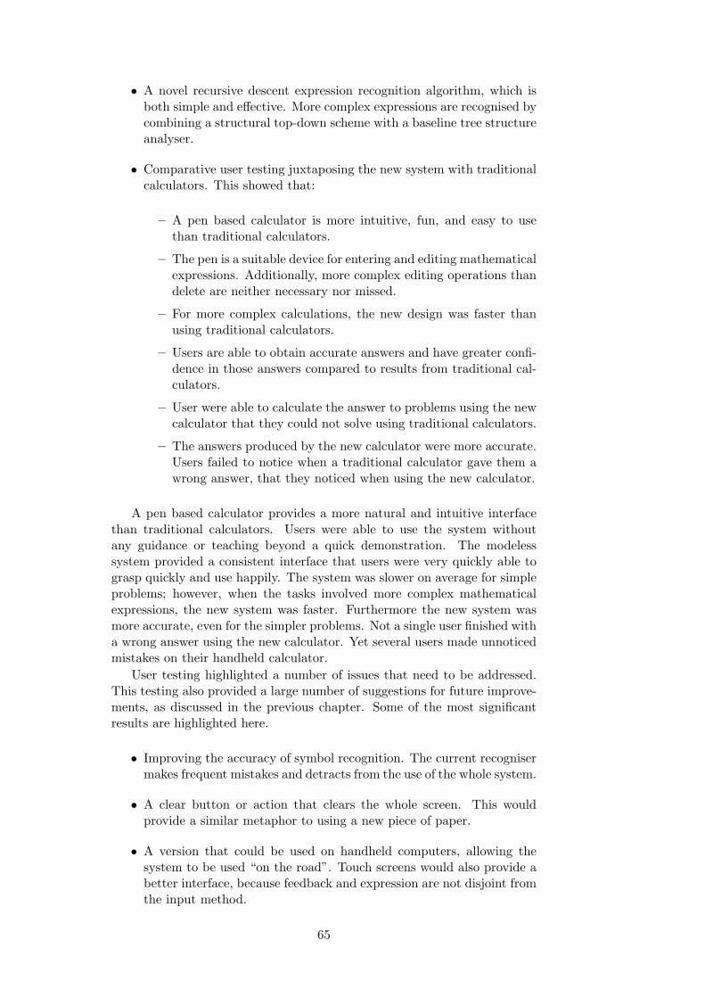
• A novel recursive descent expression recognition algorithm, which isboth simple and effective. More complex expressions are recognised bycombining a structural top-down scheme with a baseline tree structureanalyser.
• Comparative user testing juxtaposing the new system with traditionalcalculators. This showed that:
– A pen based calculator is more intuitive, fun, and easy to usethan traditional calculators.
– The pen is a suitable device for entering and editing mathematicalexpressions. Additionally, more complex editing operations thandelete are neither necessary nor missed.
– For more complex calculations, the new design was faster thanusing traditional calculators.
– Users are able to obtain accurate answers and have greater confi-dence in those answers compared to results from traditional cal-culators.
– User were able to calculate the answer to problems using the newcalculator that they could not solve using traditional calculators.
– The answers produced by the new calculator were more accurate.Users failed to notice when a traditional calculator gave them awrong answer, that they noticed when using the new calculator.
A pen based calculator provides a more natural and intuitive interfacethan traditional calculators. Users were able to use the system withoutany guidance or teaching beyond a quick demonstration. The modelesssystem provided a consistent interface that users were very quickly able tograsp quickly and use happily. The system was slower on average for simpleproblems; however, when the tasks involved more complex mathematicalexpressions, the new system was faster. Furthermore the new system wasmore accurate, even for the simpler problems. Not a single user finished witha wrong answer using the new calculator. Yet several users made unnoticedmistakes on their handheld calculator.
User testing highlighted a number of issues that need to be addressed.This testing also provided a large number of suggestions for future improve-ments, as discussed in the previous chapter. Some of the most significantresults are highlighted here.
• Improving the accuracy of symbol recognition. The current recognisermakes frequent mistakes and detracts from the use of the whole system.
• A clear button or action that clears the whole screen. This wouldprovide a similar metaphor to using a new piece of paper.
• A version that could be used on handheld computers, allowing thesystem to be used “on the road”. Touch screens would also provide abetter interface, because feedback and expression are not disjoint fromthe input method.
65

It is hoped that creation of this new calculator will prompt people torethink the methods by which we do mathematics. Calculators are currentlyrestricted by obsolete metaphors, as the testing and very creation of thissystem has shown. Ultimately, it would be great if pen based calculatorscould find a use on handheld computers and tablet PCs, as well as in schoolclassrooms, where they would be an ideal way of teaching mathematics tochildren. I am confident that the prototype developed in this thesis chartsa course in the right direction.
66

Bibliography
[1] J. Landay A. Long Jr. and L. Rowe. Pda and gesture uses in practice:Insights for designers of pen-based user interfaces. Report #CSD-97-976, Jan 1998.
[2] R. H. Anderson. Syntax Directed Recognition of Hand-Printed Two-Dimensional Mathematics, pages 436–459. Academic Press, New York,1968.
[3] R.H. Anderson. A comment on the recognition of hand-printed two-dimensional mathematical expressions, 1971.
[4] R.H. Anderson. Two-dimensional mathematical notation, pages 147–177. Springer -Verlag, 1977.
[5] S. Baumann. A simplified attribute graph grammar for high-level musicrecognition. pages 1080–1083, Montreal, Canada, Aug 1995.
[6] D. Blostein and A. Grbavec. Recognition of mathematical notation,1996.
[7] Dorothea Blostein and Andy Schuerr. Computing with graphs andgraph transformation. Software Practice and Experience, 29(3):1–21,1999.
[8] H. Bunke. Attributed programmed graph grammars and their appli-cation to schematic diagram interpretation. volume 4, pages 574–582,1982.
[9] R. Carr and D. Shafer. The Power of PenPoint. Addison-Wesley, 1991.
[10] K. Chan and D. Yeung. A simple yet robust structural approach forrecognizing on-line handwritten alphanumerical characters, Aug 1998.
[11] S. Chang. A method for the structural analysis of two-dimensionalmathematical expressions. Information Sciences, 2(3):253–272, 1970.
[12] P. Chou. Recognition of equations using a two-dimensional stochasticcontext-free grammar. Proc. SPIE Visual Communications and ImageProcessing IV, pages 852–863, Nov 1989.
[13] Cit. http://www.cs.caltech.edu/arvo/software.html.
[14] Apple computer Inc. Human Interface Guidelines: The Apple DesktopInterface. Addison Wesley, 1987.
[15] R. Johnson E. Gamma, R. Helm and J. Vlissides. Design Patterns.Addison-Wesley, 1995.
67

[16] Odaka et al. On-line recognition of handwritten characters by approxi-mating each stroke with several points. IEEE Transactions on Systems,Man, and Cybernetics, 12(6):898–903, November 1982.
[17] Yuko Eto and Masakazu Suzuki. Mathematical formula recognitionusing virtual link network. In Proceedings of the Sixth InternationalConference on Document Analysis and Recognition (ICDAR ’01), page762. IEEE Computer Society, 2001.
[18] C. Faure and Z. Wang. Automatic perception of the structure of hand-written mathematical expressions, in computer processing of handwrit-ing. World Scientific, pages 337–361, 1990.
[19] D. Goldberg and A. Goodisman. Stylus user interfaces for manipulat-ing text. In Proceedings of the 4th annual ACM symposium on Userinterface software and technology, pages 127–135. ACM Press, 1991.
[20] A. Grbavec and D. Blostein. Mathematics recognition using graphrewriting. pages 417–421, Montreal, Canada, Aug 1995.
[21] J. Redish J. Dumas. A Practical Guide to Usability Testing. Intellect.
[22] Norbert Kajler and Neil Soiffer. A survey of user interfaces for computeralgebra systems. J. Symb. Comput., 25(2):127–159, 1998.
[23] L. Lamport. LATEX: A Document Preparation System. Addison Wesley.
[24] B. Laurel and S. Mountford. The Art of Human-Computer InterfaceDesign. Addison-Wesley Longman Publishing Co., Inc., 1990.
[25] Stephane Lavirotte and Loıc Pottier. Optical formula recgonition. vol-ume 1, pages 357–361, Ulm, Germany, 1997.
[26] H. Lee and J. Wang. Design of a mathematical expression recognitionsystem. pages 1084–1087, Montreal, Canada, Aug 1995.
[27] R. Littin. The pen input of mathematical expressions. Master’s thesis,University of Waikato, 1993.
[28] Lyx. http://www.lyx.org/.
[29] Maple. http://www.maplesoft.com/.
[30] W. A. Martin. A fast parsing scheme for hand-printed mathematicalexpressions, 1967.
[31] William A. Martin. Computer input/output of mathematical expres-sions. In Proceedings of the second ACM symposium on Symbolic andalgebraic manipulation, pages 78–89. ACM Press, 1971.
[32] Mathematica. http://www.wolfram.com/products/mathematica/.
[33] Nicholas E. Matsakis. Recognition of handwritten mathematical ex-pressions, May 1999.
[34] Maxima. http://maxima.sourceforge.net/.
68

[35] A. Meyer. Pen computing: a technology overview and a vision. SIGCHIBull., 27(3):46–90, 1995.
[36] Microsoft. Microsoft Word User’s Guide, Version 6.0. Microsoft Press,1993.
[37] A. Morrel-Samuels. Clarifying the distinction between lexical and ges-tural commands. Man-Machine Studies, 32:581–590, 1990.
[38] J. Nielsen and R. Mack, editors. Usability Inspection Methods. JohnWiley & Sons Inc.
[39] I. Pavlidis, R. Singh, and N. Papanikolopoulos. Recognition of on-linehandwritten patterns through shape metamorphosis, 1996.
[40] Pencalc. http://www.cs.ust.hk/pencalc/.
[41] E. Persoon and K-S. Fu. Shape discrimination using fourier descrip-tors. IEEE Transaction on Systems, Man and Cybernetics, 7(3):170–179, Mar 1977.
[42] J. Arvo R. Zanibbi, K. Novins and K. Zanibbi. Aiding manipula-tion of handwritten mathematical expressions through style-preservingmorphs. pages 127–134, Ottawa, Canada, June 2001.
[43] Dorothea Blostein Richard Zanibbi and James R. Cordy. Baseline struc-ture analysis of handwritten mathematics notation. pages 768–773,Seattle, Washington, 2001.
[44] Dorothea Blostein Richard Zanibbi and James R. Cordy. Recognizingmathematical expressions using tree transformation. IEEE Transac-tions on Pattern Analysis and Machine Intelligence, 24(11):1455–1467,November 2002.
[45] A. C. Shaw. The formal picture description scheme as a basis for pictureprocessing systems. Information and Control, 14:9–52, 1969.
[46] B. Shneiderman. Designing the user interface: Strategies for effectivehuman-computer interaction. Addison Wesley, 1992.
[47] Steve Smithies. Freehand formula entry system. Master’s thesis, Uni-versity of Otago, Dunedin, New Zealand, May 1999.
[48] T. Starner, J. Makhoul, R. Schwartz, and G. Chou. line cursive hand-writing recognition using speech recognition techniques, 1994.
[49] C. C. Tappert. Adaptive on-line handwriting recognition. InternationalConference on Pattern Recognition, pages 1004–1007, 1984.
[50] H. Thimbleby. A new calculator and why it is necessary, 1996.
[51] H. Thimbleby. Calculators are needlessly bad, 2000.
[52] H. Twaakyondo and M. Okamoto. Structure analysis and recognitionof mathematical expressions. pages 430–437, Montreal, Canada, Aug1995.
[53] Wacom. http://www.wacom.com.
69

[54] http://will.thimbleby.net.
[55] Yanjie Zhao, Tetsuya Sakurai, Hiroshi Sugiura, and Tatsuo Torii. Amethodology of parsing mathematical notation for mathematical com-putation. In Proceedings of the 1996 international symposium on Sym-bolic and algebraic computation, pages 292–300. ACM Press, 1996.
70

Appendix A
Anonymous Questionnaire
The following pages show the anonymous questionnaire used for usabilitytesting. The results from these questionnaires are shown in appendix B
71

Thank you for taking part in my usability testing. During or after youruse of the system please answer the following questions by either circling theappropriate answer or writing in the space provided.
Answers you give here are completely confidential, and will not be lookedat till all the user-testing is finished and all questionnaires have been groupedtogether.
Questions
Have you seen the system before?How much do you normally use computers?What is your occupation?What is your overall impression of the system?
What did you feel to be the best parts of the system?
What did you feel to be the worst parts of the system?
How accurate was the system at recognising your handwriting and mathe-matics?
What do you use to normally calculate mathematics?
72
Which aspects make it better than how you normally calculate mathemat-ics?
Which aspects make it worse than how you normally calculate mathemat-ics?
What did you think about the user interface? Feedback and editing?
Did you enjoy using the system and what could be improved?
Comments
Are there any other comments you would like to make?
73

Appendix B
Result
Have you seen the system before? Yes Yes No No No Yes No No No Howmuch do you normally use computers?
• Not very often - for essays mainly
• lots
• Everyday for about 7 hours
• Lots
• Lots and Lots
• Only when I need to
• 1-4 hours a day
• 2 or 3 times a week
• Not much
What is your occupation?
• Student
• Placement officer
• Computer science student
• Student
• Doorsafe manager
• International student
• Handyman
• Mathematics student
What is your overall impression of the system?
• Its really good when you get the hang of it
• sleek styly + I want to use it
• very good
74
• very cool user friendly concept — got a few niggles that need ironingout
• new — interesting
• a lot of potential — needs to recognise my 5’s
• very good and highly intuitive
• It works very well — sometimes the recogniser seems to be a bit slug-gish. It’s easy to be confident of what I’m calculating because it dis-plays it on screen.
What did you feel to be the best parts of the system?
• Is fairly easy to use when you get the hang of it — you can write whatyou know of the sum and it works the rest out.
• sound effects — clean look — idea!
• much more natural than having to type equations in
• when the computer would fill in the blanks even if you hadn’t finishedthe sum
• add and change elements in the calculation
• it’s simplicity, use of ”question mark” — also the ability of people withpoor handwriting to produce clear equations
• the ease with which sums could be written in to the system havingbeen copied direct from ‘printed’ notation
• Easy to edit equations — adding and removing parts — it works outthe answer for me — understood nearly all of my handwriting
What did you feel to be the worst parts of the system?
• It didn’t always recognise my numbers/signs
• got confused when it didn’t understand my writing — actually I havean idea, decrease the size of the numbers when its a
• simple equation so you can sneak nos in
• Had to adjust how I wrote = to get it to work
• hand recognition (not working that well)
• The time used to clean the window
• the tablet takes a bit of getting used to and it didn’t like my number8s which I though were inoffensive
• Interpreted = as two fraction bars creating a big mess to clean up froma small error
How accurate was the system at recognising your handwriting and mathe-matics?
• Generally very good but didn’t recognise some.
75

• good for all numbers — except 4/5 had to make it recognise
• good, had problems with = and 5’s
• had trouble with some numbers + signs — but possibility of updatingthe system on my scribbling was good
• problem with getting it to delete properly and struggled to recognisemy 5’s
• almost flawless 4 is almost + but other wise no mistakes at all
What do you use to normally calculate mathematics?
• Calculator
• head – i only do simple stuff
• My head
• fingers, other people
• my head — paper or pencil — not complicated stuff
• a graphical calculator and computer programs
• an abacus (I don’t ‘do’ maths)
• pencil and paper — a calculator if I really need one — often computers
Which aspects make it better than how you normally calculate mathemat-ics?
• You don’t have to find/understand all the buttons as you do on ascientific calculator
• I am more comfortable using comps these days so I’m not scared ofusing it. Also, it’s a dream come true, someone giving me the answerjust by writing the equation
• 2 to power of what = 28 are made much easier as you don’t have torearrange anything to do the calculation
• I can see how the sum is working and edit it at will. I can draw howI see the sum in my head
• the possibility to change the calculation without starting all over again
• the way you use it is much more intuitive and saves you time in termsof writing the answer down
• the problem does not have to be converted by me into a format compre-hensible by a calculator and can do stuff I couldn’t do on a calculator
• it requires an input method I am not familiar with
• no thinking about brackets or trying to find numerical keys on a key-board — can see the computation taht it’s done. — can edit it, or addmore steps to the computation, (in the middle of the expression!)
76

Which aspects make it worse than how you normally calculate mathemat-ics?
• You have to cross out things when you’ve finished with it rather thanjust simply pressing cancel, you have to be careful about where youwrite numbers and signs, can be a bit confusing
• not as quick for simple calculations
• takes the fun out of using your head
• you can spend more time writing perfectly than doing the sum
• it didn’t recognise my numbers frequently
• learn to recognise 8’s and = signs. Maybe it easier to delete stuff -maybe somewhere on screen to press to clear the screen
• slow to recognise after input — can end up making the same errorseveral times in a row as I try to enter something and it gets it wrong
What did you think about the user interface? Feedback and editing?
• excellent — didn’t notice it that much
• v. good I found it hard to use the pen
• easy to use, edit. impressed
• I’ve always liked pens better than buttons
• very simple, really intuitive (esp. the delete gesture) nice how it addsin and calculates placeholders
Did you enjoy using the system and what could be improved?
• Yes but I got a bit confused at first.
• Include letters rather than ? ie. 2x rather than 2?
• Yes — the handwriting recognition could be better — if it were able todistinguish similar symbols and throw up a warning — the user couldre-input the symbols
• Yes, and clean the window — a possibility for deleting everything onthe screen
• the method of deleting
• yes — a lot — could do with delete all — clear page — or equivalent— extend it to cope with multiple expressions — want to see severalresults at once
Are there any other comments you would like to make?
• get a good degree dude!
• from a teachers point of view: would be great fun to try this out onpupils
• i like the explosions — Maths teachers would love it
• it works really well
77
Related Documents