PASCO scientific Student Manual 75 A Ammeter V Voltmeter Section 6 HOW ARE VALUES OF CIRCUIT VARIABLES MEASURED? INTRODUCTION People who use electric circuits for practical purposes often need to measure quantitative values of electric pressure difference and flow rate of charge. To do this they use instruments called “voltmeters” and “ammeters.” In this section you will investigate the behavior of these instruments. You will then combine these instruments in a circuit to measure the resistance of circuit components. 6.1 Commentary Your teacher will provide you with an instrument labeled “voltmeter” and with another labeled “ammeter.” The circuit diagram symbol for a voltmeter is a box labeled “V”, and the symbol for an ammeter is a box labeled “A”. There are two main types of voltmeters and ammeters: The “analog” type has a number line scale and a movable pointer, while the “digital” type provides a numerical readout. Your teacher will demonstrate the proper use of the instruments available in your classroom. Please note that connecting them directly to a battery can often damage ammeters. Follow instructions carefully! Do not connect an ammeter in any circuit until your teacher has shown you how to do this properly.

Welcome message from author
This document is posted to help you gain knowledge. Please leave a comment to let me know what you think about it! Share it to your friends and learn new things together.
Transcript

PASCO scientific Student Manual 75
A
Ammeter
V
Voltmeter
Section 6 HOW ARE VALUES OF CIRCUIT
VARIABLES MEASURED?
INTRODUCTION People who use electric circuits for practical purposes often need to measure quantitative values of electric pressure difference and flow rate of charge. To do this they use instruments called “voltmeters” and “ammeters.” In this section you will investigate the behavior of these instruments. You will then combine these instruments in a circuit to measure the resistance of circuit components. 6.1 Commentary Your teacher will provide you with an instrument labeled “voltmeter” and with another labeled “ammeter.” The circuit diagram symbol for a voltmeter is a box labeled “V”, and the symbol for an ammeter is a box labeled “A”. There are two main types of voltmeters and ammeters: The “analog” type has a number line scale and a movable pointer, while the “digital” type provides a numerical readout. Your teacher will demonstrate the proper use of the instruments available in your classroom. Please note that connecting them directly to a battery can often damage ammeters. Follow instructions carefully!
Do not connect an ammeter in any circuit until your teacher has shown you how to do this properly.

PASCO scientific Student Manual 76
INVESTIGATION ONE: WHAT DOES A “VOLTMETER” DO? The readout of an instrument labeled “voltmeter” is intended by the manufacturer to tell you the electric pressure difference between any two points on a circuit to which it is connected. In this investigation you will investigate the actual behavior of your voltmeter. 6.2 Activity: Testing the voltmeter qualitatively Each diagram below is shown with a pair of extra wires connected to two points on a circuit. Figure 6.2a shows a voltmeter connected to the free ends of one of the pairs of extra wires. Do not build the circuit yet; just study the diagrams.
L
LA
BV
L
LA
B
Figure 6.2a Figure 6.2b VOLTMETER CONNECTED EXTRA WIRES CONNECTED TO ACROSS A PAIR OF BULBS BOTH SIDES OF THE BATTERY
L
LA
B
L
LA
B
Figure 6.2c Figure 6.2d EXTRA WIRES CONNECTED TO EXTRA WIRES CONNECTED TO BOTH SIDES OF UPPER BULB BOTH SIDES OF LOWER BULB 1. Color code each of the diagrams above, including the extra wires. 2. Based on the color code, is there a pressure difference across the voltmeter in Figure 6.2a? Do you think it is equal or unequal to the pressure difference across the pair of bulbs? Why? Suppose the voltmeter shown in Figure 6.2a is connected to the free ends of the extra wires in each of the other circuits . Try to envision the pressure difference in these wires as acting on the voltmeter, and the meter reading as telling you how the voltmeter is responding to this action.
2 cells

PASCO scientific Student Manual 77
3. How would you describe the pressure difference that acts on the voltmeter when it is connected across the battery as in Figure 6.2b – compared with the pressure difference that acts on it when it is connected across the pair of bulbs as in Figure 6.2a? Do you predict these pressure differences should be the same or different? Explain your reasoning. 4. Predict how these pressure differences will compare:
a) across bulb A (as in Figure 6.2c) compared to the battery (Figure 6.2b)?
b) across bulb B (as in Figure 6.2d) compared to the battery
(Figure 6.2b)? c) across bulb A (Figure 6.2c) compared to across bulb B
(Figure 6.2d)? 6.3 Commentary The symbol for the quantitative value of electric pressure is ”V”. The symbol ”∆V“ will be used for the difference between two electric pressure values. The unit for expressing quantitative values of electric pressure and of electric pressure difference is the VOLT. Values of electric pressure difference are measured by a voltmeter in volts. D-cells are designed to maintain their (+) terminals at about 1.5 volts electric pressure higher than their (-) terminals. 6.4 Activity: Testing the voltmeter quantitatively 1. Color code the wires for the circuit diagram in Figure 6.4a, using red-to-blue for the pressure difference maintained by the battery between its terminals. Do not connect the voltmeter yet.
V =
V =
V =
V =
L
LA
B
Figure 6.4a
VOLTMETER READINGS

PASCO scientific Student Manual 78
2. Predict how many volts of electric pressure difference your red-to-blue color difference corresponds to in this situation where the battery consists of two D-cells connected in series. Explain. 3. Your teacher will provide a voltmeter. Connect the voltmeter to each of the locations indicated in Figure 6.4a, and record the readings provided by this instrument in the corresponding spaces on the circuit diagram. 4. What evidence do you observe in these instrument readings that your voltmeter is actually measuring the differences of electric pressure that exist in the circuit between the various pairs of points to which it is connected? 5. Now color code the wires for the circuit diagram in Figure 6.4b, which has two different kinds of bulbs.
V =
V =
V =
V =
R
LA
B
Figure 6.4b VOLTMETER READINGS WITH TWO DIFFERENT BULBS
6. Based on your previous measurements, and your knowledge of long and round bulbs, predict the pressure differences you will detect across each: Prediction: Round: Long: 7. Set up the circuit in Figure 6.4b. Use your voltmeter to measure the pressure difference at each of the locations shown, and record the readings in the spaces provided on the figure. 8. Did the voltmeter reading confirm your predictions for bulbs A and B? Does the brightness of bulb B also confirm the prediction? Explain.

PASCO scientific Student Manual 79
L LL LΔV= ΔV=ΔV=
L
V
9. Construct the circuit shown in Figure 6.4c. Before doing measurements, predict what you will observe. Prediction: Measure the pressure differences across each of the parts of the circuit indicated in the diagram, and record the readings in the spaces provided.
Figure 6.4c
VOLTMETER READINGS IN PARALLEL BRANCHES 10. How do the three pressure differences compare? How would they compare if the battery and the two bulbs had been connected in a series circuit? Activity 6.5: Investigating voltmeter resistance 1. Connect the circuit shown in Figure 6.5a. Describe the observed behavior of both the bulb and the voltmeter
2. What do your observations tell you about the resistance of a voltmeter?
Figure 6.5a VOLTMETER CONNECTED
IN SERIES 3. Speculate why a voltmeter would be designed with that resistance? 4. Why isn’t a voltmeter normally connected to a circuit as in Figure 6.5?

PASCO scientific Student Manual 80
INVESTIGATION TWO: USING A VOLTMETER WITH A CAPACITOR 6.6 Activity: Pressure difference during charging and discharging
L
L
V
Figure 6.6a VOLTMETER CONNECTED ACROSS A CAPACITOR
1. Color code the diagram above as a circuit in which the capacitor is fully charged. 2. Set up the circuit; observe the voltmeter while the capacitor is charging. Describe what you observe for the voltmeter reading as the capacitor is charging while the long bulbs are lit. 3. What do you think the voltmeter is “sensing”, or responding to, in the wires connected to it? What is it sensing in the capacitor plates connected to the wires? 4. Remove the battery from the circuit, but do not connect the free ends of the wires. What happens to the voltmeter reading? What is the voltmeter “sensing” now? 5. Now, reconnect the free ends of the wires and observe the voltmeter reading while the capacitor discharges. What happens to the voltmeter reading during capacitor discharging? Why is this happening?

PASCO scientific Student Manual 81
6. Repeat the charging-discharging process a few times, and sketch a graph of pressure difference as a function of time during capacitor charging. Investigate the variations using one cell, two cells and three cells in your battery case. Sketch each approximate graph below.
7. Draw a bar graph of the maximum pressure difference as a function of the number of cells.
8. According to your observations, what do you think determines the amount of the maximum pressure difference in a circuit?
Maximum Pressure Difference vs. Number of Cells
1 2 3
Pres
sure
Diff
eren
ce, i
n Vo
lts
1.5
3.0
4.5
Number of Cells
Approximate Graphs of Pressure Difference vs. Time
1.5
3.0
4.5
1.5
3.0
4.5
1.5
3.0
4.5
Time Time Time
Pres
sure
Diff
eren
ce, i
n Vo
lts
Pres
sure
Diff
eren
ce, i
n Vo
lts
Pres
sure
Diff
eren
ce, i
n Vo
lts1 Cell 2 Cells 3 Cells

PASCO scientific Student Manual 82
INVESTIGATION THREE: WHAT DOES AN AMMETER DO? DO NOT BEGIN THIS INVESTIGATION UNTIL YOUR TEACHER HAS DESCRIBED HOW TO USE AMMETERS WITHOUT DAMAGING THEM. 6.7 Activity: Testing the ammeter in series circuits 1. Using two D-cells in the battery and two long bulbs, connect each of the circuits shown below. Observe the reading on the ammeter in each case. How do the meter readings compare?
Figure 6.7a Figure 6.7b Figure 6.7c SERIES CIRCUITS WITH AMMETER
Now, replace one of the long bulbs in Figure 6.7c with a round bulb, as in the figures below. Move the ammeter around the circuit as in the previous activity.
Figure 6.7d Figure 6.7e Figure 6.7f CIRCUITS WITH AMMETER AND TWO TYPES OF BULBS
2. Explain the difference in ammeter readings from the values observed in the previous exercise. (Question 1) 6.8 Commentary The symbol for the quantitative value of flow rate is “I”. The rate of flow through a circuit component is commonly called the “current” through that component. The unit for expressing quantitative values of current is named for a French scientist, Andre Ampere. The AMPERE is often shortened simply to AMP. Values of current are measured by an ammeter in amperes (or amps).
A
L
A
LA L
R R R
A
L
A
LA L
LL L

PASCO scientific Student Manual 83
6.9 Activity: Testing the ammeter in parallel circuits Set up the circuit as shown in Figure 6.9a using two cells in the battery case.
1. Insert the ammeter at each of the locations indicated by a current symbol (I) in Figure 6.9a. Record the readings provided by this instrument in the corresponding spaces on the figure — labeled I1, I2, I3, and I4. (I1 and I4 represent the current in the ‘trunk’ of the circuit, and I2 and I3 represent the current in the ‘branches’.
Figure 6.9a INSERTING AMMETER AT
FOUR DIFFERENT LOCATIONS 2. What evidence do you have that the ammeter is accurately measuring the flow rates that exist in all parts of the circuit? 6.10 Activity: Investigating ammeter resistance 1. Predict: Suppose you were to “short circuit” the long bulb in Figure 6.10a using a wire as shown in the diagram. That would, in effect, remove the long bulb’s resistance from the circuit. How would you expect the ammeter’s reading to change?
Figure 6.10a
SHORTING OUT ONE BULB
NOTE: Have the instructor check the circuit and make sure that the ammeter is connected for at least a 300 mA scale. With excessive current, the ammeter will be damaged.
2. Set up the circuit and do the experiment. Was your prediction correct? What did you observe? 3. Next connect the circuit shown in Figure 6.10b. Compare the meter reading to what you observed in Activity 6.10 a.
3
L L
I =
L L
1I =
I2
4
I ==
L
R
A
2 cells

PASCO scientific Student Manual 84
4. Considering the change in bulb brightness for the long and the round bulb, does the ammeter act like a short circuit?
Figure 6.10b AMMETER AROUND
LONG BULB 5. What can you conclude about the resistance of the ammeter? Explain. 6. Why would an instrument designer plan to manufacture an ammeter with this resistance? 7. Speculate why it is easy to damage an ammeter. INVESTIGATION FOUR: HOW DO WE MEASURE RESISTANCE? Besides light bulb filaments, there are circuit components called “resistors” (usually made of carbon), that hinder charge flow but do not emit light. These can be obtained with just about any resistance value. In this section you will learn how to measure resistance. 6.11 Commentary The symbol ”R“ is used for the quantitative value of the resistance of a circuit component. The unit for expressing resistance values is the Ohm (symbol Ω) named for Georg Ohm, a German physicist and high school teacher. In circuit diagrams, resistors are indicated by the symbol at the right.
L
R2 cells
A
Resistor Symbol

PASCO scientific Student Manual 85
V
A
RX
6.12 Activity: Measuring resistance In this activity you will determine the quantitative value of resistance. Predict in advance: if you find that a low pressure difference across a bulb or resistor results in a large current, would you refer to the bulb as having a high or low resistance? Prediction: Measuring the resistance of a circuit component requires both a voltmeter and an ammeter (or milliammeter). The procedure is as follows:
(a) Connect the resistor to a battery. (b) Use a voltmeter to measure the pressure difference across the resistor in volts. (c) Use an ammeter to measure the current through the resistor in amperes. (d) Prepare a graph in which you plot voltage (x-axis) vs. current (y-axis). (e) Determine the value of the slope of the line; this value represents the amount of
resistance in volts/amperes, or ohms. Your teacher will provide two different resistors, labeled as Rx and Ry. Set up the circuit shown in Figure 6.12, with Rx as the resistance. Then repeat the procedure for Ry. 1. Using 1 cell, then 2 cells, and then 3 cells, measure the pressure difference ∆V across the resistor labeled Rx and simultaneously the current through Rx. Repeat the measurements for Ry. Record the data in the table below. Then plot the data for both resistors on the same set of axes and determine the slopes. Figure 6.12 CIRCUIT FOR DETERMINING RESISTANCE

PASCO scientific Student Manual 86
TABLE 6.12
Rx Ry
Cells
Pressure Difference (in volts)
Flow Rate or Current (in amps)
Slope in Volts Amps (ohms)
Pressure Difference (in volts)
Flow Rate or Current (in amps)
Slope in Volts Amps (ohms)
1
2
3
Graph of Voltage vs. Current for Two Resistors 2. Compare the slopes you found for Rx and Ry using the same three voltages. What can you conclude about the values of the resistance for the two resistors?
This calculation can be expressed by means of the following important equation: Resistance = Voltage Difference or in symbols R = ∆V
Current I
This equation says that the ratio of ∆V to I represents the amount of resistance R in a resistor. It says that the amount of resistance R in a resistor is equivalent to the amount of pressure difference ∆V (or voltage) that must be applied across the resistor for flow rate I to occur. That makes sense, because a large resistance value does require a large pressure difference to drive flow rate through the resistor.
Current, in amps
Vol
tage
, in
volts
0
5 V
PASCO scientific Student Manual 87
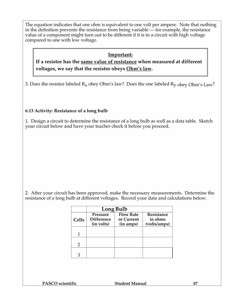
The equation indicates that one ohm is equivalent to one volt per ampere. Note that nothing in the definition prevents the resistance from being variable — for example, the resistance value of a component might turn out to be different if it is in a circuit with high voltage compared to one with low voltage.
Important: If a resistor has the same value of resistance when measured at different voltages, we say that the resistor obeys Ohm’s law.
3. Does the resistor labeled Rx obey Ohm’s law? Does the one labeled Ry obey Ohm’s Law? 6.13 Activity: Resistance of a long bulb 1. Design a circuit to determine the resistance of a long bulb as well as a data table. Sketch your circuit below and have your teacher check it before you proceed. 2. After your circuit has been approved, make the necessary measurements. Determine the resistance of a long bulb at different voltages. Record your data and calculations below.
Long Bulb
Cells Pressure
Difference (in volts)
Flow Rate or Current (in amps)
Resistance in ohms
(volts/amps) 1
2
3

PASCO scientific Student Manual 88
A B
Current, in amps
Vol
tage
, in
volts
0
5 V
3. Does a long bulb obey Ohm’s Law? (Suggestion: To answer this question, plot a graph of pressure difference vs. flow rate at different voltages.) 6.14 Commentary: The “equivalent resistance” idea Suppose you have some boxes, with terminals connected to combinations of bulbs inside the boxes. Each box will behave like a resistor, and the resistance of the box is called the “equivalent resistance” of the bulbs contained in it. In Figures 6.14a and 6.14b, the shaded areas labeled A and B represent two such boxes. The equivalent resistances of the boxes can be compared by connecting them to the same battery and measuring the flow rates that the battery voltage drives through them. Figure 6.14a Figure 6.14b
CIRCUITS WITH EQUIVALENT RESISTANCES 6.15 Activity: Equivalent resistance for parallel and series resistors In Figures 6.15a and 6.15b, the shaded areas indicate that we will be comparing the equivalent resistance of two long bulbs in parallel with the equivalent resistance of a single long bulb. Do not set up these circuits until you have answered questions 1 and 2.
Figure 6.15a Figure 6.15b COMPARING EQUIVALENT RESISTANCES
L LL
A A

PASCO scientific Student Manual 89
1. Explain how observing the ammeter readings will enable you to decide if the equivalent resistance of two bulbs in parallel is greater than, less than, or equal to the resistance of a single bulb. 2 What does your intuition tell you about the equivalent resistance of two bulbs in parallel compared to the resistance of a single bulb? 3. Now, connect your battery as in Figure 6.15a and then as in Figure 6.15b. How does the equivalent resistance of the two parallel bulbs in circuit 6.15b compare to the resistance of the single bulb in circuit 6.15a? What is the evidence? Remove the pair of bulbs and reconnect them in series, as in Figure 6.15c. Then connect your battery as in Figure 6.15a and then as in Figure 6.15c.
Figure 6.15a Figure 6.15c COMPARING EQUIVALENT RESISTANCES
4. How does the equivalent resistance of the two series bulbs in circuit 6.15c compare to the resistance of the single bulb in circuit 6.15a? What is the evidence? 5. Color-code the circuits in Figures 6.15a, 6.15b and 6.15c below, and use the colors to explain the ammeter readings observed in 6.15b and 6.15c, compared to 6.15a.
L
LL LL
AA A
Figure 6.15a Figure 6.15b Figure 6.15c
L
A
L
L
A
PASCO scientific Student Manual 90
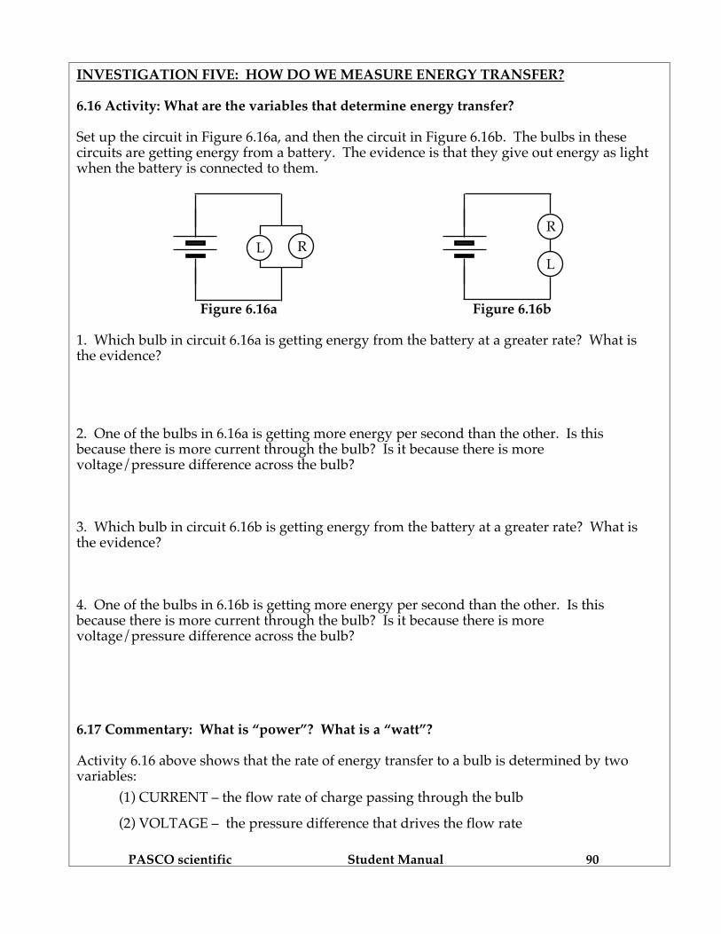
INVESTIGATION FIVE: HOW DO WE MEASURE ENERGY TRANSFER? 6.16 Activity: What are the variables that determine energy transfer? Set up the circuit in Figure 6.16a, and then the circuit in Figure 6.16b. The bulbs in these circuits are getting energy from a battery. The evidence is that they give out energy as light when the battery is connected to them.
L
RL R
Figure 6.16a Figure 6.16b 1. Which bulb in circuit 6.16a is getting energy from the battery at a greater rate? What is the evidence? 2. One of the bulbs in 6.16a is getting more energy per second than the other. Is this because there is more current through the bulb? Is it because there is more voltage/pressure difference across the bulb? 3. Which bulb in circuit 6.16b is getting energy from the battery at a greater rate? What is the evidence? 4. One of the bulbs in 6.16b is getting more energy per second than the other. Is this because there is more current through the bulb? Is it because there is more voltage/pressure difference across the bulb? 6.17 Commentary: What is “power”? What is a “watt”? Activity 6.16 above shows that the rate of energy transfer to a bulb is determined by two variables: (1) CURRENT – the flow rate of charge passing through the bulb (2) VOLTAGE – the pressure difference that drives the flow rate

PASCO scientific Student Manual 91
We would like to find out how these variables combine to determine the rate of transfer of energy when both of them are varying. We will use the professional term POWER for rate of transfer of energy.
"POWER" MEANS AMOUNT OF ENERGY TRANSFERRED PER SECOND. Energy transferred to a bulb comes from a battery or some other energy source. When we need to distinguish between transfer to one part of a circuit and from some other part, we will use the terms POWER INPUT and POWER OUTPUT. The unit of power is the WATT. The magnitude of the watt is defined as follows:
When a 1 volt pressure difference drives a 1 ampere flow rate through a bulb, the rate of transfer of energy to that bulb is defined to be 1 WATT of power.
Figure 6.17 shows a “unit” cell connected to a “unit” bulb. Chemical activity in this imaginary cell maintains a 1 volt pressure difference in its terminals, and the resistance of this special bulb allows the cell to drive a 1 ampere flow rate through it. The symbol P is used for amount of power input. Therefore, P = 1 watt for a unit bulb lit by a unit cell, illustrated in Figure 6.17.
Figure 6.17
DEFINING ONE WATT OF POWER INPUT TO AN IMAGINARY BULB
“Unit” cells and bulbs cannot be bought in stores, but they make circuit diagrams especially easy to analyze. This will help us find out how current and voltage combine to determine power input to resistors. 6.18 Activity: How do current and voltage jointly determine power transfer? We can use the definition of the watt provided in Figure 6.17 to determine the power input to a box that contains any combination of “unit” bulbs. Figures 6.18a and 6.18b show how “unit” cells in series can provide 1 volt across each bulb in a variety of different combinations that let different battery voltages drive different currents through different boxes.
∆V = 1 voltPower input to the bulb is P = 1 watt
= 1 ampereI
I

PASCO scientific Student Manual 92
Two shaded boxes with different combinations of “unit” bulbs are shown in Figures 6.18a and 6.18b. Here’s how to determine the magnitudes of the variables: POWER input to a box - is equal to - the number of “unit” bulbs in box CURRENT through the box - is equal to - the number of parallel paths in box VOLTAGE that drives current - is equal to - the number of “unit” cells in battery
Figure 6.18a BOX WITH 8 UNIT BULBS
Figure 6.18b BOX WITH 6 UNIT BULBS
Imagine an arrowtail with one shaft drawn next to each bulb in Figures 6.18a and 6.18b, representing a 1 ampere flow rate through each bulb. 1. On Figures 6.18a and 6.18b, draw arrowtails to represent current into and out of the shaded boxes. Draw one shaft in the arrowtail for each ampere. 2. Near each shaded box in Figures 6.18a and 6.18b, write P = ? (a number for watts of power input to the box.) Near each arrowtail, write I = ? (a number for amperes of flow rate into and out of the box.) Near each battery, write ∆V = ? (a number for volts of pressure difference across the box.) 3. Look at the numbers you placed on Figures 6.18a and 6.18b. Write an equation that describes the pattern of relationship between P, I, and ∆V.
PASCO scientific Student Manual 93
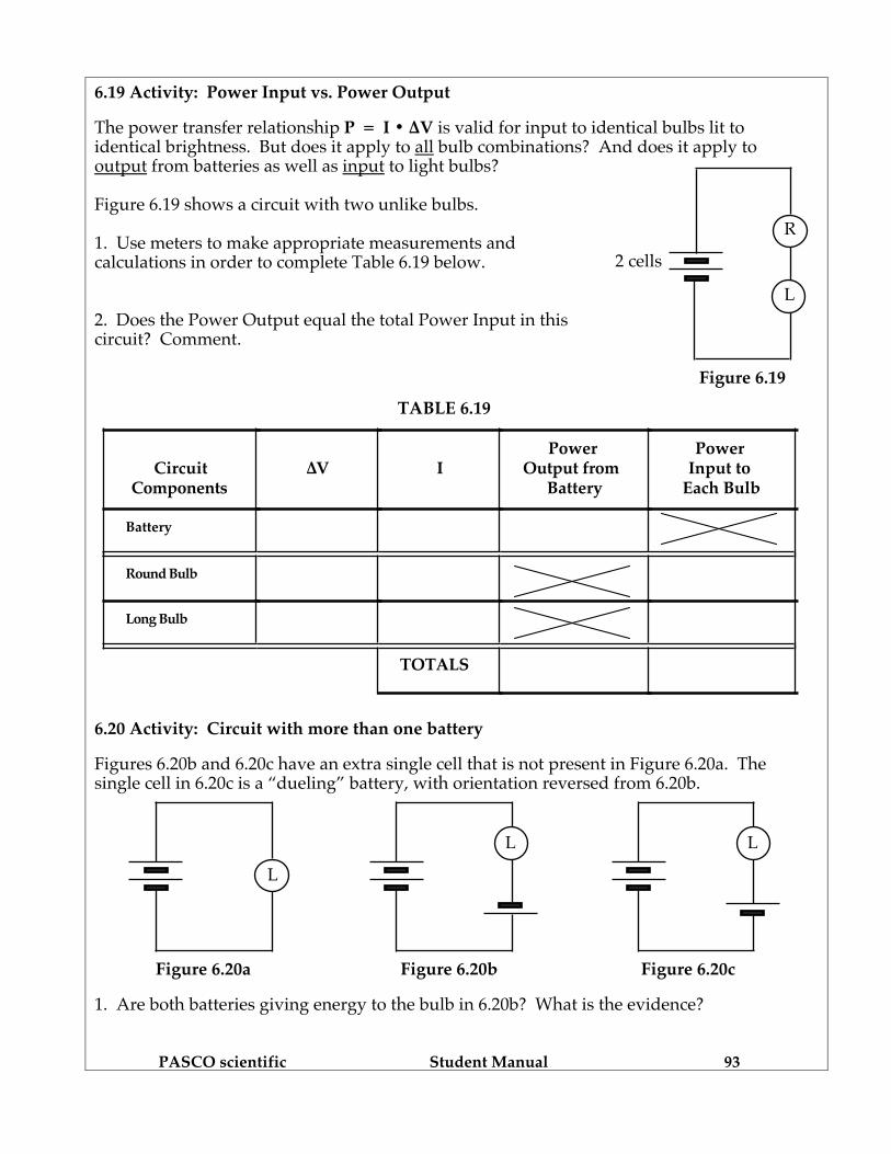
Figure 6.19 shows a circuit with two unlike bulbs.
1. Use meters to make appropriate measurements and calculations in order to complete Table 6.19 below.
2. Does the Power Output equal the total Power Input in this circuit? Comment.
L
R
2 cells
6.19 Activity: Power Input vs. Power Output The power transfer relationship P = I • ∆V is valid for input to identical bulbs lit to identical brightness. But does it apply to all bulb combinations? And does it apply to output from batteries as well as input to light bulbs? Figure 6.19 shows a circuit with two unlike bulbs. 1. Use meters to make appropriate measurements and calculations in order to complete Table 6.19 below. 2. Does the Power Output equal the total Power Input in this circuit? Comment.
Figure 6.19
TABLE 6.19
CircuitComponents
∆V IPower
Output from Battery
Power Input to
Each Bulb
Battery
Round Bulb
Long Bulb
TOTALS
6.20 Activity: Circuit with more than one battery Figures 6.20b and 6.20c have an extra single cell that is not present in Figure 6.20a. The single cell in 6.20c is a “dueling” battery, with orientation reversed from 6.20b.
Figure 6.20a Figure 6.20b Figure 6.20c 1. Are both batteries giving energy to the bulb in 6.20b? What is the evidence?
L L
L

PASCO scientific Student Manual 94
CircuitComponents ∆V I
Power Giving
Power Receiving
2 Cell Battery
Single Cell
Bulb
TOTALS
2. Are both batteries giving energy to the bulb in 6.20c? What is the evidence? 3. Could the single cell in 6.20c be getting energy from the stronger 2-cell battery? Explain your reasoning.
Using meters, make appropriate measurements from the circuit in Figure 6.20c only and complete Table 6.20.
TABLE 6.20
?? 4. Does the power output in this circuit equal the power input? Explain.
5. Is the circuit in Figure 6.20c “re-energizing” the single cell? Explain.
6.21 Activity: Energy storage in capacitors You may be able to answer the following questions from previous experience. If not, try doing the experiments first. 1. When a capacitor is being charged through light bulbs, is some of the energy stored in the battery being transferred to the capacitor as well as to the bulbs? What is the evidence?

PASCO scientific Student Manual 95
2. Compare this situation to pushing a plunger into a sealed air syringe and then letting the plunger go.
3. Compare the amount of energy stored in a 100,000 µf capacitor with the amount stored in a 25,000 µf capacitor that has been charged with the same battery. What is the evidence?

PASCO scientific Student Manual 96
SUMMARY EXERCISE 1. Explain what electrical quantity each of the two meters measures, and what units are used for the measurement. Ammeter: Voltmeter: 2. In terms of experimental procedures, how is resistance determined? What units are used for measuring resistance? 3. A good measuring instrument should have as little interference as possible on the system being measured. For both an ammeter and a voltmeter, describe:
a) whether the resistance of an ammeter and a voltmeter is high or low, and why: Ammeter: Voltmeter:
b) how the meter should be connected in a circuit in relation to the circuit elements: Ammeter: Voltmeter:
c) why each meter needs to have its particular resistance to be a good measuring device:
Ammeter: Voltmeter:

PASCO scientific Student Manual 97
4. Describe how the resistance of the X and Y resistors was affected by the different voltages you used. Describe how the resistance of the long bulb was affected by the different voltages you used. Compare the behavior of the two kinds of devices. Does each type of device obey Ohm’s law?
5. For a circuit containing a battery, two bulbs and a capacitor in series, sketch graphs describing how the voltage across each element and the current through each element will behave during the charging of the capacitor.
Time Time Time
Capacitor Battery Light Bulbs
Time Time Time
Capacitor Battery Light Bulbs

PASCO scientific Student Manual 98
6. Consider the equivalent resistance of each of the following four combinations of bulbs. List each in order from the least resistance to the greatest resistance. Prediction:
Then devise a method and build circuits to check your answers. Actual:
7. Power is the rate of energy transfer, so which household bulb would be brighter: a 100-watt or a 60-watt bulb? Explain. 8. Which bulb (a 100-watt or a 60-watt) has the largest resistance? Use the relationship P = ∆V • I in your explanation. 9. Compare a rechargeable battery and a capacitor: a) In what ways are they similar? b) In what ways are they different?
R RR L R L
A B C D
Related Documents