Hindawi Publishing Corporation International Journal of Vehicular Technology Volume 2013, Article ID 718920, 9 pages http://dx.doi.org/10.1155/2013/718920 Research Article A 7-Level Single DC Source Cascaded H-Bridge Multilevel Inverter with a Modified DTC Scheme for Induction Motor-Based Electric Vehicle Propulsion Farid Khoucha, 1,2 Khoudir Marouani, 2 Mohamed Benbouzid, 1 Abdelaziz Kheloui, 2 and Abdeslam Mamoune 1 1 University of Brest, EA 4325 LBMS, Kergoat Street, CS 93837, 29238 Brest Cedex 03, France 2 Ecole Militaire Polytechnique, UER ELT, 16111 Algiers, Algeria Correspondence should be addressed to Mohamed Benbouzid; [email protected] Received 1 September 2012; Revised 15 January 2013; Accepted 16 January 2013 Academic Editor: Lingyang Song Copyright © 2013 Farid Khoucha et al. is is an open access article distributed under the Creative Commons Attribution License, which permits unrestricted use, distribution, and reproduction in any medium, provided the original work is properly cited. is paper presents a new hybrid cascaded H-bridge multilevel inverter motor drive DTC scheme for electric vehicles where each phase of the inverter can be implemented using a single DC source. Traditionally, each phase of the inverter requires DC source for 2 + 1 output voltage levels. In this paper, a scheme is proposed that allows the use of a single DC source as the first DC source which would be available from batteries or fuel cells, with the remaining (−1) DC sources being capacitors. is scheme can simultaneously maintain the capacitors of DC voltage level and produce a nearly sinusoidal output voltage due to its high number of output levels. In this context, high performances and efficient torque and flux control are obtained, enabling a DTC solution for hybrid multilevel inverter powered induction motor drives intended for electric vehicle propulsion. Simulations and experiments show that the proposed multilevel inverter and control scheme are effective and very attractive for embedded systems such as automotive applications. 1. Introduction Currently, automotive applications such as EV’s seem to constitute an increasingly effective alternative to conven- tional vehicles, allowing vehicle manufacturers to fulfill users requirements (dynamic performances and fuel consumption) and environmental constraints (pollutant emissions reduc- tion) [1]. e electric propulsion system is the heart of EV. It consists of the motor drive, transmission device, and wheels. In fact, the motor drive, comprising the electric motor, the power converter, and the electronic controller, is the core of the EV propulsion system. e motor drive is configured to respond to a torque demand set by the driver [2]. e induction motor seems to be a very interesting solution for EV’s propulsion. FOC and DTC have emerged as the standard industrial solutions to achieve high dynamic performance [3–5]. However some drawbacks of both meth- ods have motivated important research efforts in the last decades. Particularly for DTC, the high torque ripple and the variable switching frequency introduced by the hys- teresis comparators have been extensively addressed [6, 7]. In addition, several contributions that combine DTC prin- ciples together with PWM and SVM have been reported to correct these problems. is approach is based on the load angle control, from which a voltage reference vector is computed which is finally modulated by the inverter [8]. Although one major feature of classic DTC is the absence of modulators and linear controllers, this approach has shown significant improvements and achieves similar dynamic performance. On the other hand, power converter technology is continuously developing, and cascaded multilevel inverters have become a very attractive solution for EV applications, due to its modular structure, higher voltage capability, reduced common mode voltages, near sinusoidal outputs, and smaller or even no output filter [9–12]. In general, cascaded multilevel inverter may be classified in two groups.

Welcome message from author
This document is posted to help you gain knowledge. Please leave a comment to let me know what you think about it! Share it to your friends and learn new things together.
Transcript
Hindawi Publishing CorporationInternational Journal of Vehicular TechnologyVolume 2013 Article ID 718920 9 pageshttpdxdoiorg1011552013718920
Research ArticleA 7-Level Single DC Source Cascaded H-BridgeMultilevel Inverter with a Modified DTC Scheme forInduction Motor-Based Electric Vehicle Propulsion
Farid Khoucha12 Khoudir Marouani2 Mohamed Benbouzid1
Abdelaziz Kheloui2 and Abdeslam Mamoune1
1 University of Brest EA 4325 LBMS Kergoat Street CS 93837 29238 Brest Cedex 03 France2 Ecole Militaire Polytechnique UER ELT 16111 Algiers Algeria
Correspondence should be addressed to Mohamed Benbouzid mohamedbenbouziduniv-brestfr
Received 1 September 2012 Revised 15 January 2013 Accepted 16 January 2013
Academic Editor Lingyang Song
Copyright copy 2013 Farid Khoucha et alThis is an open access article distributed under the Creative Commons Attribution Licensewhich permits unrestricted use distribution and reproduction in any medium provided the original work is properly cited
This paper presents a new hybrid cascaded H-bridge multilevel inverter motor drive DTC scheme for electric vehicles where eachphase of the inverter can be implemented using a single DC source Traditionally each phase of the inverter requires 119899 DC sourcefor 2119899 + 1 output voltage levels In this paper a scheme is proposed that allows the use of a single DC source as the first DC sourcewhich would be available from batteries or fuel cells with the remaining (119899 minus 1) DC sources being capacitors This scheme cansimultaneously maintain the capacitors of DC voltage level and produce a nearly sinusoidal output voltage due to its high numberof output levels In this context high performances and efficient torque and flux control are obtained enabling a DTC solution forhybrid multilevel inverter powered induction motor drives intended for electric vehicle propulsion Simulations and experimentsshow that the proposed multilevel inverter and control scheme are effective and very attractive for embedded systems such asautomotive applications
1 Introduction
Currently automotive applications such as EVrsquos seem toconstitute an increasingly effective alternative to conven-tional vehicles allowing vehicle manufacturers to fulfill usersrequirements (dynamic performances and fuel consumption)and environmental constraints (pollutant emissions reduc-tion) [1]
The electric propulsion system is the heart of EV Itconsists of the motor drive transmission device and wheelsIn fact the motor drive comprising the electric motor thepower converter and the electronic controller is the core ofthe EV propulsion system The motor drive is configured torespond to a torque demand set by the driver [2]
The induction motor seems to be a very interestingsolution for EVrsquos propulsion FOC and DTC have emergedas the standard industrial solutions to achieve high dynamicperformance [3ndash5] However some drawbacks of both meth-ods have motivated important research efforts in the last
decades Particularly for DTC the high torque ripple andthe variable switching frequency introduced by the hys-teresis comparators have been extensively addressed [6 7]In addition several contributions that combine DTC prin-ciples together with PWM and SVM have been reportedto correct these problems This approach is based on theload angle control from which a voltage reference vectoris computed which is finally modulated by the inverter [8]Although one major feature of classic DTC is the absence ofmodulators and linear controllers this approach has shownsignificant improvements and achieves similar dynamicperformance
On the other hand power converter technology iscontinuously developing and cascaded multilevel invertershave become a very attractive solution for EV applicationsdue to its modular structure higher voltage capabilityreduced common mode voltages near sinusoidal outputsand smaller or even no output filter [9ndash12] In generalcascaded multilevel inverter may be classified in two groups
2 International Journal of Vehicular Technology
The first one refers to the amplitude of isolated DC sourcesdevoted to supply each H-bridge cell If the amplitude ofall sources is equal then the inverter is called symmetricalotherwise if at least one of the sources presents differentamplitude then it will be called asymmetrical The secondclassification labels the multilevel inverter whether hybridor not If the converter is implemented with differentsemiconductor device technologies different nature of DCsources (fuel cells batteries and supercapacitors) andor if itpresents a hybrid modulation strategy then it is classified ashybrid [13ndash15] This structure greatly simplifies the convertercomplexity
The proposed control algorithm eliminates the need ofadditional isolated DC sourcesThe control strategy regulatesthe DC link voltages of capacitors connected to the smallestvoltages of a two-cell 7-level cascaded H-bridge inverter [16]Specifically and in comparison to previous works [17 18] theproposed control does not use an angle for capacitor voltageregulation but a comparison voltage level This will facilitatea DSP implementation
The carried out simulations and experiments validatethe voltage control strategy and confirm the high dynamicperformance of the proposed method presenting very lowtorque ripple
2 Multilevel Inverter Topology
The power circuit of the cascaded H-bridge multilevelinverter is illustrated in Figure 1The inverter is composed bythe series connection of power cells each one containing anH-bridge inverter and an isolatedDC source In the particularcase of asymmetric inverters these sources are not equal(1198811gt 1198812)The asymmetry of the input voltages can reduce or
when properly designed eliminate redundant output levelsmaximizing the number of different levels generated by theinverterTherefore this topology can achieve the same outputvoltage quality with less number of semiconductors spacecosts and internal fault probability than the symmetric fedtopology
A particular cell 119894 can generate three voltage levels(+119881119894 0 minus119881
119894) The total inverter output voltage for a particular
phase 119895 is then defined by
119907119894119873
=
119898
sum
119895=1
119907119894119895
=
119898
sum
119895=1
119881119895(1198781198951
minus 1198781198952) 119894 isin 119886 119887 119888 (1)
where 119907119894119873
is the total output voltage of phase 119894 (resp theneutral of the inverter119873) the output voltage of cell of phaseand the switching state associated to cell
It should be noticed how the output voltage of one cellis defined by one of the four binary combinations of theswitching state with ldquo1rdquo and ldquo0rdquo representing the ldquoOnrdquo andldquoOffrdquo states of the corresponding switch respectively
The inverter generates different voltage levels (eg aninverter with 119898 = 4 cells can generate (2119898+1 minus 1 = 31)different voltage levels)When using three-phase systems thenumber of different voltage vectors is given by 3119899
119897(119899119897minus 1) + 1
where 119899119897is the number of levels For example for the 119898 = 4
case with 31 levels there are 2791 different voltage vectors
IMCell A1 main inverter
DC linkRectifier H inverter
11987812
11987812
11987811
11987811Cell B1
Cell B2
Cell C1
Cell C2
NCell B1 auxiliary inverter
a b c
119907119886119899 119907119887119899 119907119888119899
Figure 1 Hybrid cascaded multilevel converter topology
Table 1 7-Level asymmetric cascaded inverter switching states
119899119897
Cell 1 Cell 2 Total11987811
11987812
1199071198861
11987821
11987822
1199071198862
119907119886119873
1 1 0 3119907DC 0 0 0 3119907DC
2 1 0 3119907DC 0 1 minus119907DC 2119907DC
3 0 0 0 1 0 119907DC 119907DC
4 0 0 0 0 0 0 05 0 0 0 0 1 minus119907DC minus119907DC
6 0 1 minus3119907DC 1 0 119907DC minus2119907DC
7 0 1 minus3119907DC 0 0 0 minus3119907DC
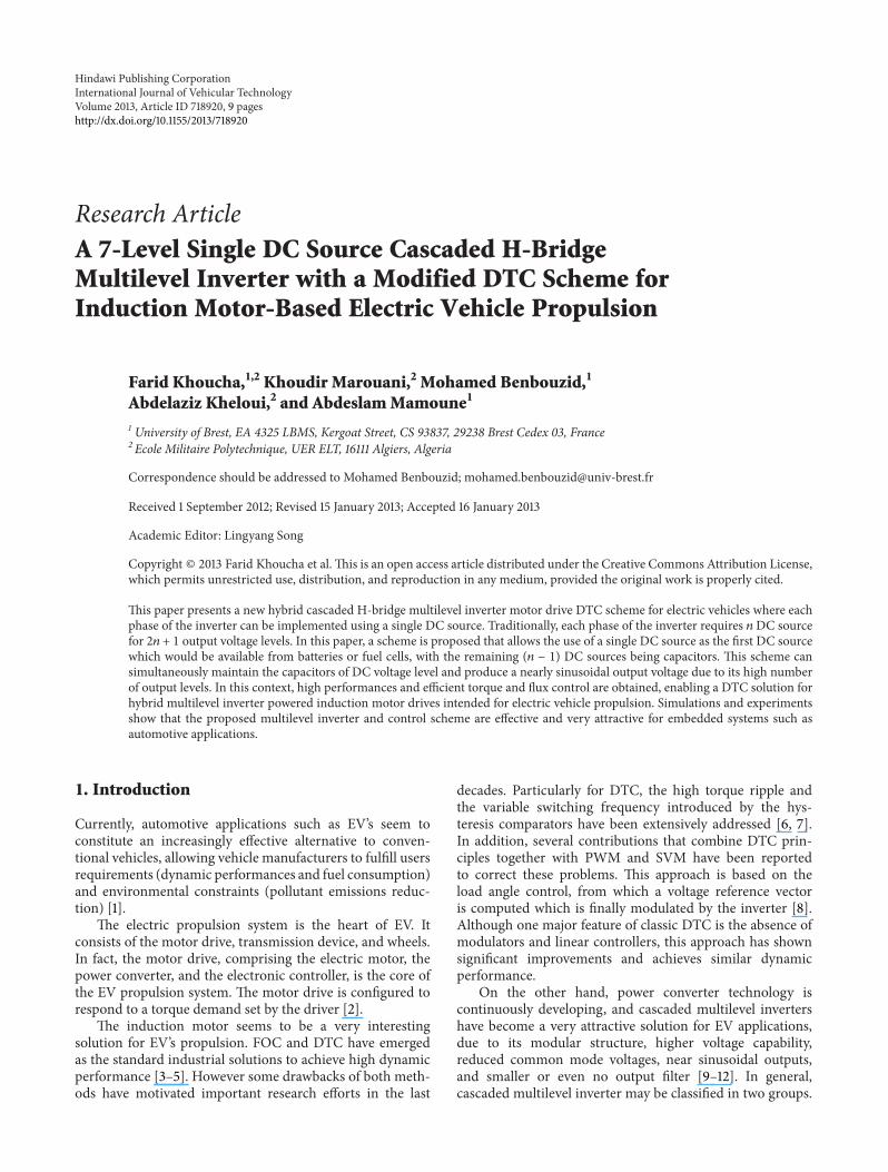
Table 1 summarizes the output levels for an asymmetric 7-level inverter using only 119898 = 2 cells per phase (only phasevoltage is given) An example of the voltage waveform for anasymmetric 7-level inverter is illustrated by Figure 2
3 DTC-PWM Control
31 DTC Basic Principles The stator voltage space vector (119907119904)
of an induction motor is related to the stator flux vector 120595119904in
a stator fixed coordinate system by
119907119904= 119877119904119894119904+
119889120595119904
119889119905
(2)
Neglecting the voltage drop in the stator resistance 119877119904
the stator flux vector is the time integral of the stator voltagevector Hence for a small sampling period 119879
119904 (2) can be
expressed by
Δ120595119904asymp 119907119904119879119904 (3)
On the other hand the motor torque is related to thestator and rotor fluxes by
119879119890=
3
2
119901
119896
120590119871119904
1003816100381610038161003816120595119904
1003816100381610038161003816
1003816100381610038161003816120595119903
1003816100381610038161003816sin (120575) (4)
where 119896 = 119871119898119871119904 If both flux magnitudes are kept constant
in (4) the torque can be controlled directly by changing
International Journal of Vehicular Technology 3
1000
002 0025 003 035 004 0045 005 0055 006
1198811198861
(V)
Time (s)
minus100
500
minus50
002 0025 003 035 004 0045 005 0055 006
1198811198862
(V)
Time (s)
200
0
002 0025 003 035 004 0045005 0055 006
119881119886119899
(V)
Time (s)
minus200
Figure 2Asymmetricmultilevel inverterwith 7-level output voltagesynthesis
the load angle This can be easily achieved since variationsin the stator flux vector change the load angle due to slowerrotor flux dynamics
Considering (3) and (4) it follows that the stator voltagevector can be used to manipulate the load angle and conse-quently to control the torque
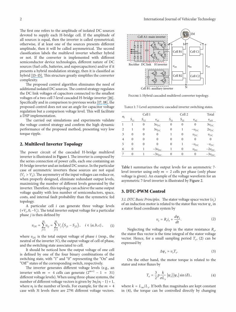
32 Flux and Torque Control by Load Angle Tracking Intraditional DTC the influence over the load angle of eachvoltage vector generated by the inverter is determined andstored in a lookup table according to the stator flux positionin the complex plane This is difficult to extend for multilevelinverter fed drives where the complexity increases in hugeproportions in relation to the levels generated by the inverterTherefore it is easier to look at the problem in a differentway the torque error can be used to generate a reference loadangle 120575
lowast necessary to correct the torque behavior Then thedesired load angle can be used to compute the exact voltagevector that will produce the necessary flux variationΔ120595
119904This
principle is illustrated in Figure 3 Note that once providedthe reference load angle 120575
lowast the reference stator flux vector120595lowast
119904can be computed by
120595lowast
119904=
1003816100381610038161003816120595lowast
119904
1003816100381610038161003816cos (120575lowast + 120579
119903) + 119895
1003816100381610038161003816120595lowast
119904
1003816100381610038161003816sin (120575
lowast+ 120579119903) (5)
where |120595lowast
119904| is the fixed stator flux amplitude reference and 120579
119903
is the rotor flux vector angle Note that (120575lowast + 120579119903) corresponds
to the reference stator flux vector angle 120579lowast
119904
Then the desired stator voltage vector 119907lowast119904can be obtained
by
119907119904asymp
Δ120595119904
119879119904
=
120595lowast
119904minus 120595119904
119879119904
(6)
Finally 119907lowast
119904has to be generated by the inverter This
is commonly performed with PWM or SVM for 2-level
120579119904
120579119903120572
120575
120575lowast
120573
120595lowast120573
120595lowast119904
120595lowast120572
120595119903
120595119904
Δ120595119904 asymp 119907lowast119904 119879119904
Figure 3 Stator voltage vector influence over the stator flux vector
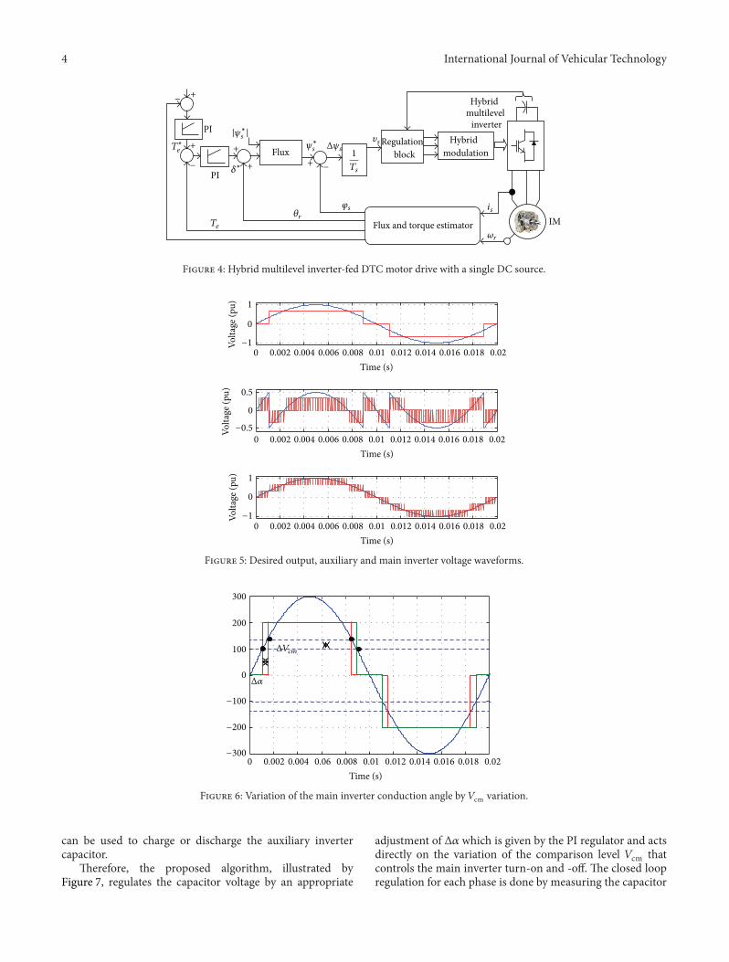
inverters [19] The use of a multilevel inverter will reducethe torque ripple amplitude due to the reduction of therate of change of the common-mode voltage (number ofstep variations in a fixed time span) and in this caseusing the hybrid modulation method [20] a fixed-frequencyoutput voltage will be obtained concentrating the voltagespectrum around the carrier frequency of the small powercell Hence themost important drawbacks of traditional DTCare corrected A simplified control diagram of the proposedstrategy is shown in Figure 4 The outer speed control loop isomitted
4 Hybrid Modulation Strategy
The hybrid modulation is specially conceived for the asym-metric multilevel H-bridge inverter structure [14]
The basic idea is to take advantage of the different powerrates among the cells to reduce switching losses and improvethe converter efficiency From Figure 5 it can be seen thatthe inverter generates a rectangular waveform which is atthe same frequency of the reference (turn-on and -off onlyone time during a half reference cycle) The remaining ofthe output voltage second trace in Figure 5 is synthesized bythe auxiliary inverter at high switching frequency (with sinu-soidal PWM) This completes the generation of a multilevelsteppedwaveformwith a high-frequency component (similarto a multicarrier-based PWM) but with the difference thatfewer switching losses are produced to achieve it Typicaloutput waveform of the inverter using this modulation isshown in the third trace of Figure 5 Note that the outputhas 7 different voltage levels given by all the possible com-binations of the series connection of (+119881DC 0 minus119881DC) and(+2119881DC 0 minus2119881DC)
5 Capacitor Voltage Control
Capacitor voltage control in the auxiliary inverter is achallenging task [14 21] The proposed control method isbased on a hybrid modulation that consists of adjustingthe main inverter turn-on This indeed corresponds toadjusting the active and reactive powers that the maininverter injects to the load (if 120572 is chosen to be exactly18∘ the main inverter injects only active power) By shiftingthe voltage waveform synthesized by the main inverter(Figure 6) one could also inject some reactive power which
4 International Journal of Vehicular Technology
IM
Regulationblock
Hybridmultilevel
inverterHybrid
modulationFlux
PI
119879119890
119879lowast119890
120575lowast
119894119904
120596119903
Flux and torque estimator
1
119879119904
+
+ +
+ +
minus
minus minus
120593119904
PI
120579119903
∣120595lowast119904 ∣ 119907119904120595lowast
119904 Δ120595119904
Figure 4 Hybrid multilevel inverter-fed DTC motor drive with a single DC source
1
0
0minus1
0002 0004 0006 0008 001 0012 0014 0016 0018 002
Time (s)
Volta
ge (p
u)
05
0
0minus05
0002 0004 0006 0008 001 0012 0014 0016 0018 002
Time (s)
Volta
ge (p
u)
1
0
0minus1
0002 0004 0006 0008 001 0012 0014 0016 0018 002
Time (s)
Volta
ge (p
u)
Figure 5 Desired output auxiliary and main inverter voltage waveforms
300
200
100
0
minus100
minus200
minus3000 0002 0004 006 0008 001 0012 0014 0016 0018 002
Time (s)
Δ119881119888119898
Δ120572
Figure 6 Variation of the main inverter conduction angle by 119881cm variation
can be used to charge or discharge the auxiliary invertercapacitor
Therefore the proposed algorithm illustrated byFigure 7 regulates the capacitor voltage by an appropriate
adjustment of Δ120572 which is given by the PI regulator and actsdirectly on the variation of the comparison level 119881cm thatcontrols the main inverter turn-on and -off The closed loopregulation for each phase is done by measuring the capacitor
International Journal of Vehicular Technology 5
SHPWM
+
+
+
++
+minus minus
minus
minus
PI
c119894119888
1198811198862
1198811198861 ref
119881119888 ref
Δ119881119888 119881119888
119881119888
119881cm
Δ119881cm
119881119886119904 ref
SecondaryH-bridgeinverter
MainH-bridgeinverter
Figure 7 Closed-loop control of the capacitor voltages
Figure 8 7-level single DC source cascaded H-bridge multilevelinverter
voltage From the capacitors voltage error the PI regulatorgives directly the necessary Δ119881cm to be added to the initialcomparison level which leads to changing the conductionangle 120572 of the main inverter that allows the secondaryinverter capacitor charging
6 Experimental and Simulations Results
61 Hybrid Modulation Strategy Implementation The above-discussed hybrid modulation strategy has been experimen-tally implemented (Figure 8) The proposed hybrid mod-ulation strategy main results are illustrated by Figure 9As abovementioned the inverter generates a rectangularwaveform which is at the same frequency of the reference(Figure 9(a)) The remaining of the output voltage is synthe-sized by the auxiliary inverter at high switching frequencywith sinusoidal PWM (Figure 9(b)) Figure 9(c) shows thetypical output waveform of the 7-level inverter under hybridmodulation
62 Simulation Tests on an Induction Motor-Based EVPropulsion To evaluate the dynamic performances of theproposed control strategy numerical simulations have beencarried out on an EV propelled by an induction motorsupplied with 7-level single DC source cascaded multilevelinverter (Figure 4)
Output voltageReference voltage
(a) Main H-bridge inverter voltages
Output voltageReference voltage
Auxiliary source current
(b) Secondary H-bridge inverter voltages and auxiliary source (feeding theH-bridge) current
Auxiliarysourcecurrent
Voltage supplycurrent
Load current
7-level inverterphase voltage
(c) The main outputs
Figure 9 Desired output main auxiliary and inverter voltage andcurrent waveforms of the realized 7-level inverter under hybridmodulation
Simulations were done using the standardized ECE-15and EUDCdriving cycle [22]The achieved performances areillustrated by Figures 10 to 15
The simulation results show that the speed referencerequired by the driver is well-tracked as shown byFigure 10 One can see that the induction motor developedtorque presents fewer ripples compared to a traditional DTC
6 International Journal of Vehicular Technology
180
160
140
120
100
80
60
40
20
0
minus200 2 4 6 8 10 12
SpeedReference speed
Time (s)
Spee
d (r
ads
)
Figure 10 Speed with the ECE-15 + EUDC driving cycle
4
35
3
25
2
1
15
05
0
minus050 2 4 6 8 10 12
TorqueReference torque
Time (s)
Torq
ue (N
m)
Figure 11 Reference and developed torques
(Figure 11) This is due to the quality of the voltage supplyingthe inverter (Figure 12) Consequently the stator currentsare almost sinusoidal (Figure 13) and better dynamicsare obtained operating practically with constant flux(Figure 14)
Figure 15 shows the capacitor voltages waveforms whichsupply each auxiliary H-bridge of the three phase hybridmultilevel inverter One can notice the oscillations aroundthe reference Moreover these voltages are quiet identicalHowever their difference becomes very large when there isa significant acceleration or deceleration requested by thedriver Indeed in these cases different amounts of energyare required due to the induction motor operating point fastvariation
Time (s)0 2 4 6 8 10 12
400
300
200
100
0
minus200
minus100
minus300
minus400
Out
put v
olta
ge (V
)
Figure 12 Output voltage waveform
Time (s)
20
15
10
5
0
minus5
minus10
minus150 2 4 6 8 10 12
Curr
ent (
A)
ibic
ia
Figure 13 Stator currents waveforms
The above-presented simulation results confirm thatindependently of the requested speed and torque the capac-itor voltages are controlled and the validity of the proposedcontrol approach is proven
7 Conclusion
In this paper a control strategy has been proposed for a hybridcascaded multilevel inverter with a modified DTC schemeintended for induction motor-based EV propulsion In thiscase the main inverter uses a single DC voltage source andthe auxiliary inverter capacitor voltages are controlled in eachphase In addition DTC-PWM allows the operation with afixed switching frequency the reduction in the torque ripplewithout output filter and high-performance torque and fluxcontrol
The proposed control method simplifies the DTC appli-cation in embedded systems by reducing the inverter cost
International Journal of Vehicular Technology 7
09
08
06
07
05
04
03
02
01
00 2 4 6 8 10 12
Flux
mag
nitu
de (W
b)
Time (s)
0802
0801
08
0799
0798
0797
11 110211004 11008 11012 11016
Time (s)
Flux
mag
nitu
de (W
b)
(a) Flux magnitude
1
08
06
04
02
0
minus02
minus04
minus06
minus08
minus1minus1 minus08 minus06 minus04 minus02 0 02 04 06 08 1
Ψ119902
120595119889
(b) Flux locus
Figure 14 Magnitude and locus of the stator flux in the DTC-PWM
102
100
98
96
94
92
900 2 4 6 8 10 12
Time (s)
Volta
ge1198811198881(V
)
(a) Phase a
102
100
98
96
94
92
900 2 4 6 8 10 12
Time (s)
Volta
ge1198811198882(V
)
(b) Phase b102
100
98
96
94
92
900 2 4 6 8 10 12
Time (s)
Volta
ge1198811198883(V
)
(c) Phase c
1005
100
995
99
985
98
975
97
965
960 2 4 6 8 10 12
Capa
cito
r vol
tage
(V)
Time (s)
1198811198882
1198811198881 1198811198883
119881ref
(d) Capacitor voltage comparison zoom
Figure 15 Capacitor voltage waveforms
8 International Journal of Vehicular Technology
Table 2 Rated data of the simulated induction motor
1 kW 50Hz 400230V 3459 A 1420 rpm119877119904= 467Ω 119877
119903= 8Ω 119871
119904= 119871119903= 0347H 119871
119898= 0366H
119869 = 006 kgsdotm2 120573 = 0042Nmsdotsec
and complexity (by decreasing the semiconductor and thesource numbers) Moreover there is no need for hysteresiscomparators and lookup tables All these key features makethe proposed control approach very attractive for embeddedsystems such as automotive applications
Appendix
See Table 2
Nomenclature
EV Electric vehicleDTC Direct torque controlFOC Field-oriented controlPWM Pulse width modulationSVM Space vector modulation119904 (119903) Stator (rotor) index119907 (119894) Voltage (current)120595 Flux119879119890 Electromagnetic torque
119877 Resistance119871 (119871119898) Inductance (mutual inductance)
120590 Leakage coefficient 120590 = 1 minus 1198712
119898119871119904119871119903
120575 Load angle119901 Pole pair number
References
[1] C C Chan A Bouscayrol and K Chen ldquoElectric hybrid andfuel cell vehicles architectures and modellingrdquo IEEE Transac-tions on Vehicular Technology vol 59 no 2 pp 589ndash598 2010
[2] M Zeraoulia M E H Benbouzid and D Diallo ldquoElectricmotor drive selection issues for HEV propulsion systems acomparative studyrdquo IEEE Transactions on Vehicular Technologyvol 55 no 6 pp 1756ndash1764 2006
[3] D O Neacsu and K Rajashekara ldquoComparative analysis oftorque-controlled IM drives with applications in electric andhybrid vehiclesrdquo IEEE Transactions on Power Electronics vol 16no 2 pp 240ndash247 2001
[4] A Haddoun M E H Benbouzid D Diallo R AbdessemedJ Ghouili and K Srairi ldquoA loss-minimization DTC schemefor EV induction motorsrdquo IEEE Transactions on VehicularTechnology vol 56 no 1 pp 81ndash88 2007
[5] D Casadei G Serra A Tani L Zarri and F ProfumoldquoPerformance analysis of a speed-sensorless induction motordrive based on a constant switching-frequency DTC schemerdquoIEEE Transactions on Industry Applications vol 39 no 2 pp476ndash484 2003
[6] C A Martins X Roboam T A Meynard and A S CarvalholdquoSwitching frequency imposition and ripple reduction in DTCdrives by using a multilevel converterrdquo IEEE Transactions onPower Electronics vol 17 no 2 pp 286ndash297 2002
[7] J Rodrıguez J Pontt S Kouro and P Correa ldquoDirect torquecontrol with imposed switching frequency in an 11-level cas-caded inverterrdquo IEEE Transactions on Industrial Electronics vol51 no 4 pp 827ndash833 2004
[8] G S Buja and M P Kazmierkowski ldquoDirect torque control ofPWM inverter-fed ACmotorsmdasha surveyrdquo IEEE Transactions onIndustrial Electronics vol 51 no 4 pp 744ndash757 2004
[9] M Malinowski K Gopakumar J Rodriguez and M A PerezldquoA survey on cascaded multilevel invertersrdquo IEEE Transactionson Industrial Electronics vol 57 no 7 pp 2197ndash2206 2010
[10] P Cortes A Wilson S Kouro J Rodriguez and H Abu-Rub ldquoModel predictive control of multilevel cascaded H-bridgeinvertersrdquo IEEE Transactions on Industrial Electronics vol 57no 8 pp 2691ndash2699 2010
[11] J Dixon J Pereda C Castillo and S Bosch ldquoAsymmetricalmultilevel inverter for traction drives using only one DCsupplyrdquo IEEE Transactions on Vehicular Technology vol 59 no8 pp 3736ndash3743 2010
[12] J Rodriguez J-S Lai and F Z Peng ldquoMultilevel inverters asurvey of topologies controls and applicationsrdquo IEEE Transac-tions on Industrial Electronics vol 49 no 4 pp 724ndash738 2002
[13] F Khoucha S M Lagoun K Marouani A Kheloui and M EH Benbouzid ldquoHybrid cascaded H-bridge multilevel-inverterinduction-motor-drive direct torque control for automotiveapplicationsrdquo IEEE Transactions on Industrial Electronics vol57 no 3 pp 892ndash899 2010
[14] Z Du L M Tolbert B Ozpineci and J N Chiasson ldquoFunda-mental frequency switching strategies of a seven-level hybridcascaded H-bridge multilevel inverterrdquo IEEE Transactions onPower Electronics vol 24 no 1 pp 24ndash22 2009
[15] C Rech and J R Pinheiro ldquoImpact of hybrid multilevel modu-lation strategies on input and output harmonic performancesrdquoIEEE Transactions on Power Electronics vol 22 no 3 pp 967ndash977 2007
[16] F Khoucha A Ales A Khoudiri K Marouani M E H Ben-bouzid and A Kheloui ldquoA 7-level single DC source cascadedH-bridgemultilevel inverters control using hybridmodulationrdquoin Proceedings of the 19th International Conference on ElectricalMachines (ICEM rsquo10) pp 1ndash5 Rome Italy September 2010
[17] J Liao K Corzine and M Ferdowsi ldquoA new control methodfor single-DC-source cascaded H-bridge multilevel convertersusing phase-shiftmodulationrdquo inProceedings of the 23rdAnnualIEEE Applied Power Electronics Conference and Exposition(APEC rsquo08) pp 886ndash890 Austin Tex USA February 2008
[18] S Kouro R Bernai H Miranda J Rodrıguez and J PonttldquoDirect torque control with reduced switching losses for asym-metric multilevel inverter fed induction motor drivesrdquo inProceedings of the 41st IEEE IAS AnnualMeeting pp 2441ndash2446Tampa Fla USA October 2006
[19] D Casadei F Profumo G Serra and A Tani ldquoFOC and DTCtwo viable schemes for induction motors torque controlrdquo IEEETransactions on Power Electronics vol 17 no 5 pp 779ndash7872002
[20] M Veenstra and A Rufer ldquoControl of a hybrid asymmetricmultilevel inverter for competitive medium-voltage industrialdrivesrdquo IEEE Transactions on Industry Applications vol 41 no2 pp 655ndash664 2005
[21] J Liao K Wan and M Ferdowsi ldquoCascaded H-bridge mul-tilevel invertersmdasha reexaminationrdquo in Proceedings of the IEEEVehicle Power and Propulsion Conference (VPPC rsquo07) pp 203ndash207 Arlington Va USA September 2007
International Journal of Vehicular Technology 9
[22] A Haddoun M E H Benbouzid D Diallo R Abdessemed JGhouili and K Srairi ldquoModeling analysis and neural networkcontrol of an EV electrical differentialrdquo IEEE Transactions onIndustrial Electronics vol 55 no 6 pp 2286ndash2294 2008
2 International Journal of Vehicular Technology
The first one refers to the amplitude of isolated DC sourcesdevoted to supply each H-bridge cell If the amplitude ofall sources is equal then the inverter is called symmetricalotherwise if at least one of the sources presents differentamplitude then it will be called asymmetrical The secondclassification labels the multilevel inverter whether hybridor not If the converter is implemented with differentsemiconductor device technologies different nature of DCsources (fuel cells batteries and supercapacitors) andor if itpresents a hybrid modulation strategy then it is classified ashybrid [13ndash15] This structure greatly simplifies the convertercomplexity
The proposed control algorithm eliminates the need ofadditional isolated DC sourcesThe control strategy regulatesthe DC link voltages of capacitors connected to the smallestvoltages of a two-cell 7-level cascaded H-bridge inverter [16]Specifically and in comparison to previous works [17 18] theproposed control does not use an angle for capacitor voltageregulation but a comparison voltage level This will facilitatea DSP implementation
The carried out simulations and experiments validatethe voltage control strategy and confirm the high dynamicperformance of the proposed method presenting very lowtorque ripple
2 Multilevel Inverter Topology
The power circuit of the cascaded H-bridge multilevelinverter is illustrated in Figure 1The inverter is composed bythe series connection of power cells each one containing anH-bridge inverter and an isolatedDC source In the particularcase of asymmetric inverters these sources are not equal(1198811gt 1198812)The asymmetry of the input voltages can reduce or
when properly designed eliminate redundant output levelsmaximizing the number of different levels generated by theinverterTherefore this topology can achieve the same outputvoltage quality with less number of semiconductors spacecosts and internal fault probability than the symmetric fedtopology
A particular cell 119894 can generate three voltage levels(+119881119894 0 minus119881
119894) The total inverter output voltage for a particular
phase 119895 is then defined by
119907119894119873
=
119898
sum
119895=1
119907119894119895
=
119898
sum
119895=1
119881119895(1198781198951
minus 1198781198952) 119894 isin 119886 119887 119888 (1)
where 119907119894119873
is the total output voltage of phase 119894 (resp theneutral of the inverter119873) the output voltage of cell of phaseand the switching state associated to cell
It should be noticed how the output voltage of one cellis defined by one of the four binary combinations of theswitching state with ldquo1rdquo and ldquo0rdquo representing the ldquoOnrdquo andldquoOffrdquo states of the corresponding switch respectively
The inverter generates different voltage levels (eg aninverter with 119898 = 4 cells can generate (2119898+1 minus 1 = 31)different voltage levels)When using three-phase systems thenumber of different voltage vectors is given by 3119899
119897(119899119897minus 1) + 1
where 119899119897is the number of levels For example for the 119898 = 4
case with 31 levels there are 2791 different voltage vectors
IMCell A1 main inverter
DC linkRectifier H inverter
11987812
11987812
11987811
11987811Cell B1
Cell B2
Cell C1
Cell C2
NCell B1 auxiliary inverter
a b c
119907119886119899 119907119887119899 119907119888119899
Figure 1 Hybrid cascaded multilevel converter topology
Table 1 7-Level asymmetric cascaded inverter switching states
119899119897
Cell 1 Cell 2 Total11987811
11987812
1199071198861
11987821
11987822
1199071198862
119907119886119873
1 1 0 3119907DC 0 0 0 3119907DC
2 1 0 3119907DC 0 1 minus119907DC 2119907DC
3 0 0 0 1 0 119907DC 119907DC
4 0 0 0 0 0 0 05 0 0 0 0 1 minus119907DC minus119907DC
6 0 1 minus3119907DC 1 0 119907DC minus2119907DC
7 0 1 minus3119907DC 0 0 0 minus3119907DC
Table 1 summarizes the output levels for an asymmetric 7-level inverter using only 119898 = 2 cells per phase (only phasevoltage is given) An example of the voltage waveform for anasymmetric 7-level inverter is illustrated by Figure 2
3 DTC-PWM Control
31 DTC Basic Principles The stator voltage space vector (119907119904)
of an induction motor is related to the stator flux vector 120595119904in
a stator fixed coordinate system by
119907119904= 119877119904119894119904+
119889120595119904
119889119905
(2)
Neglecting the voltage drop in the stator resistance 119877119904
the stator flux vector is the time integral of the stator voltagevector Hence for a small sampling period 119879
119904 (2) can be
expressed by
Δ120595119904asymp 119907119904119879119904 (3)
On the other hand the motor torque is related to thestator and rotor fluxes by
119879119890=
3
2
119901
119896
120590119871119904
1003816100381610038161003816120595119904
1003816100381610038161003816
1003816100381610038161003816120595119903
1003816100381610038161003816sin (120575) (4)
where 119896 = 119871119898119871119904 If both flux magnitudes are kept constant
in (4) the torque can be controlled directly by changing
International Journal of Vehicular Technology 3
1000
002 0025 003 035 004 0045 005 0055 006
1198811198861
(V)
Time (s)
minus100
500
minus50
002 0025 003 035 004 0045 005 0055 006
1198811198862
(V)
Time (s)
200
0
002 0025 003 035 004 0045005 0055 006
119881119886119899
(V)
Time (s)
minus200
Figure 2Asymmetricmultilevel inverterwith 7-level output voltagesynthesis
the load angle This can be easily achieved since variationsin the stator flux vector change the load angle due to slowerrotor flux dynamics
Considering (3) and (4) it follows that the stator voltagevector can be used to manipulate the load angle and conse-quently to control the torque
32 Flux and Torque Control by Load Angle Tracking Intraditional DTC the influence over the load angle of eachvoltage vector generated by the inverter is determined andstored in a lookup table according to the stator flux positionin the complex plane This is difficult to extend for multilevelinverter fed drives where the complexity increases in hugeproportions in relation to the levels generated by the inverterTherefore it is easier to look at the problem in a differentway the torque error can be used to generate a reference loadangle 120575
lowast necessary to correct the torque behavior Then thedesired load angle can be used to compute the exact voltagevector that will produce the necessary flux variationΔ120595
119904This
principle is illustrated in Figure 3 Note that once providedthe reference load angle 120575
lowast the reference stator flux vector120595lowast
119904can be computed by
120595lowast
119904=
1003816100381610038161003816120595lowast
119904
1003816100381610038161003816cos (120575lowast + 120579
119903) + 119895
1003816100381610038161003816120595lowast
119904
1003816100381610038161003816sin (120575
lowast+ 120579119903) (5)
where |120595lowast
119904| is the fixed stator flux amplitude reference and 120579
119903
is the rotor flux vector angle Note that (120575lowast + 120579119903) corresponds
to the reference stator flux vector angle 120579lowast
119904
Then the desired stator voltage vector 119907lowast119904can be obtained
by
119907119904asymp
Δ120595119904
119879119904
=
120595lowast
119904minus 120595119904
119879119904
(6)
Finally 119907lowast
119904has to be generated by the inverter This
is commonly performed with PWM or SVM for 2-level
120579119904
120579119903120572
120575
120575lowast
120573
120595lowast120573
120595lowast119904
120595lowast120572
120595119903
120595119904
Δ120595119904 asymp 119907lowast119904 119879119904
Figure 3 Stator voltage vector influence over the stator flux vector
inverters [19] The use of a multilevel inverter will reducethe torque ripple amplitude due to the reduction of therate of change of the common-mode voltage (number ofstep variations in a fixed time span) and in this caseusing the hybrid modulation method [20] a fixed-frequencyoutput voltage will be obtained concentrating the voltagespectrum around the carrier frequency of the small powercell Hence themost important drawbacks of traditional DTCare corrected A simplified control diagram of the proposedstrategy is shown in Figure 4 The outer speed control loop isomitted
4 Hybrid Modulation Strategy
The hybrid modulation is specially conceived for the asym-metric multilevel H-bridge inverter structure [14]
The basic idea is to take advantage of the different powerrates among the cells to reduce switching losses and improvethe converter efficiency From Figure 5 it can be seen thatthe inverter generates a rectangular waveform which is atthe same frequency of the reference (turn-on and -off onlyone time during a half reference cycle) The remaining ofthe output voltage second trace in Figure 5 is synthesized bythe auxiliary inverter at high switching frequency (with sinu-soidal PWM) This completes the generation of a multilevelsteppedwaveformwith a high-frequency component (similarto a multicarrier-based PWM) but with the difference thatfewer switching losses are produced to achieve it Typicaloutput waveform of the inverter using this modulation isshown in the third trace of Figure 5 Note that the outputhas 7 different voltage levels given by all the possible com-binations of the series connection of (+119881DC 0 minus119881DC) and(+2119881DC 0 minus2119881DC)
5 Capacitor Voltage Control
Capacitor voltage control in the auxiliary inverter is achallenging task [14 21] The proposed control method isbased on a hybrid modulation that consists of adjustingthe main inverter turn-on This indeed corresponds toadjusting the active and reactive powers that the maininverter injects to the load (if 120572 is chosen to be exactly18∘ the main inverter injects only active power) By shiftingthe voltage waveform synthesized by the main inverter(Figure 6) one could also inject some reactive power which
4 International Journal of Vehicular Technology
IM
Regulationblock
Hybridmultilevel
inverterHybrid
modulationFlux
PI
119879119890
119879lowast119890
120575lowast
119894119904
120596119903
Flux and torque estimator
1
119879119904
+
+ +
+ +
minus
minus minus
120593119904
PI
120579119903
∣120595lowast119904 ∣ 119907119904120595lowast
119904 Δ120595119904
Figure 4 Hybrid multilevel inverter-fed DTC motor drive with a single DC source
1
0
0minus1
0002 0004 0006 0008 001 0012 0014 0016 0018 002
Time (s)
Volta
ge (p
u)
05
0
0minus05
0002 0004 0006 0008 001 0012 0014 0016 0018 002
Time (s)
Volta
ge (p
u)
1
0
0minus1
0002 0004 0006 0008 001 0012 0014 0016 0018 002
Time (s)
Volta
ge (p
u)
Figure 5 Desired output auxiliary and main inverter voltage waveforms
300
200
100
0
minus100
minus200
minus3000 0002 0004 006 0008 001 0012 0014 0016 0018 002
Time (s)
Δ119881119888119898
Δ120572
Figure 6 Variation of the main inverter conduction angle by 119881cm variation
can be used to charge or discharge the auxiliary invertercapacitor
Therefore the proposed algorithm illustrated byFigure 7 regulates the capacitor voltage by an appropriate
adjustment of Δ120572 which is given by the PI regulator and actsdirectly on the variation of the comparison level 119881cm thatcontrols the main inverter turn-on and -off The closed loopregulation for each phase is done by measuring the capacitor
International Journal of Vehicular Technology 5
SHPWM
+
+
+
++
+minus minus
minus
minus
PI
c119894119888
1198811198862
1198811198861 ref
119881119888 ref
Δ119881119888 119881119888
119881119888
119881cm
Δ119881cm
119881119886119904 ref
SecondaryH-bridgeinverter
MainH-bridgeinverter
Figure 7 Closed-loop control of the capacitor voltages
Figure 8 7-level single DC source cascaded H-bridge multilevelinverter
voltage From the capacitors voltage error the PI regulatorgives directly the necessary Δ119881cm to be added to the initialcomparison level which leads to changing the conductionangle 120572 of the main inverter that allows the secondaryinverter capacitor charging
6 Experimental and Simulations Results
61 Hybrid Modulation Strategy Implementation The above-discussed hybrid modulation strategy has been experimen-tally implemented (Figure 8) The proposed hybrid mod-ulation strategy main results are illustrated by Figure 9As abovementioned the inverter generates a rectangularwaveform which is at the same frequency of the reference(Figure 9(a)) The remaining of the output voltage is synthe-sized by the auxiliary inverter at high switching frequencywith sinusoidal PWM (Figure 9(b)) Figure 9(c) shows thetypical output waveform of the 7-level inverter under hybridmodulation
62 Simulation Tests on an Induction Motor-Based EVPropulsion To evaluate the dynamic performances of theproposed control strategy numerical simulations have beencarried out on an EV propelled by an induction motorsupplied with 7-level single DC source cascaded multilevelinverter (Figure 4)
Output voltageReference voltage
(a) Main H-bridge inverter voltages
Output voltageReference voltage
Auxiliary source current
(b) Secondary H-bridge inverter voltages and auxiliary source (feeding theH-bridge) current
Auxiliarysourcecurrent
Voltage supplycurrent
Load current
7-level inverterphase voltage
(c) The main outputs
Figure 9 Desired output main auxiliary and inverter voltage andcurrent waveforms of the realized 7-level inverter under hybridmodulation
Simulations were done using the standardized ECE-15and EUDCdriving cycle [22]The achieved performances areillustrated by Figures 10 to 15
The simulation results show that the speed referencerequired by the driver is well-tracked as shown byFigure 10 One can see that the induction motor developedtorque presents fewer ripples compared to a traditional DTC
6 International Journal of Vehicular Technology
180
160
140
120
100
80
60
40
20
0
minus200 2 4 6 8 10 12
SpeedReference speed
Time (s)
Spee
d (r
ads
)
Figure 10 Speed with the ECE-15 + EUDC driving cycle
4
35
3
25
2
1
15
05
0
minus050 2 4 6 8 10 12
TorqueReference torque
Time (s)
Torq
ue (N
m)
Figure 11 Reference and developed torques
(Figure 11) This is due to the quality of the voltage supplyingthe inverter (Figure 12) Consequently the stator currentsare almost sinusoidal (Figure 13) and better dynamicsare obtained operating practically with constant flux(Figure 14)
Figure 15 shows the capacitor voltages waveforms whichsupply each auxiliary H-bridge of the three phase hybridmultilevel inverter One can notice the oscillations aroundthe reference Moreover these voltages are quiet identicalHowever their difference becomes very large when there isa significant acceleration or deceleration requested by thedriver Indeed in these cases different amounts of energyare required due to the induction motor operating point fastvariation
Time (s)0 2 4 6 8 10 12
400
300
200
100
0
minus200
minus100
minus300
minus400
Out
put v
olta
ge (V
)
Figure 12 Output voltage waveform
Time (s)
20
15
10
5
0
minus5
minus10
minus150 2 4 6 8 10 12
Curr
ent (
A)
ibic
ia
Figure 13 Stator currents waveforms
The above-presented simulation results confirm thatindependently of the requested speed and torque the capac-itor voltages are controlled and the validity of the proposedcontrol approach is proven
7 Conclusion
In this paper a control strategy has been proposed for a hybridcascaded multilevel inverter with a modified DTC schemeintended for induction motor-based EV propulsion In thiscase the main inverter uses a single DC voltage source andthe auxiliary inverter capacitor voltages are controlled in eachphase In addition DTC-PWM allows the operation with afixed switching frequency the reduction in the torque ripplewithout output filter and high-performance torque and fluxcontrol
The proposed control method simplifies the DTC appli-cation in embedded systems by reducing the inverter cost
International Journal of Vehicular Technology 7
09
08
06
07
05
04
03
02
01
00 2 4 6 8 10 12
Flux
mag
nitu
de (W
b)
Time (s)
0802
0801
08
0799
0798
0797
11 110211004 11008 11012 11016
Time (s)
Flux
mag
nitu
de (W
b)
(a) Flux magnitude
1
08
06
04
02
0
minus02
minus04
minus06
minus08
minus1minus1 minus08 minus06 minus04 minus02 0 02 04 06 08 1
Ψ119902
120595119889
(b) Flux locus
Figure 14 Magnitude and locus of the stator flux in the DTC-PWM
102
100
98
96
94
92
900 2 4 6 8 10 12
Time (s)
Volta
ge1198811198881(V
)
(a) Phase a
102
100
98
96
94
92
900 2 4 6 8 10 12
Time (s)
Volta
ge1198811198882(V
)
(b) Phase b102
100
98
96
94
92
900 2 4 6 8 10 12
Time (s)
Volta
ge1198811198883(V
)
(c) Phase c
1005
100
995
99
985
98
975
97
965
960 2 4 6 8 10 12
Capa
cito
r vol
tage
(V)
Time (s)
1198811198882
1198811198881 1198811198883
119881ref
(d) Capacitor voltage comparison zoom
Figure 15 Capacitor voltage waveforms
8 International Journal of Vehicular Technology
Table 2 Rated data of the simulated induction motor
1 kW 50Hz 400230V 3459 A 1420 rpm119877119904= 467Ω 119877
119903= 8Ω 119871
119904= 119871119903= 0347H 119871
119898= 0366H
119869 = 006 kgsdotm2 120573 = 0042Nmsdotsec
and complexity (by decreasing the semiconductor and thesource numbers) Moreover there is no need for hysteresiscomparators and lookup tables All these key features makethe proposed control approach very attractive for embeddedsystems such as automotive applications
Appendix
See Table 2
Nomenclature
EV Electric vehicleDTC Direct torque controlFOC Field-oriented controlPWM Pulse width modulationSVM Space vector modulation119904 (119903) Stator (rotor) index119907 (119894) Voltage (current)120595 Flux119879119890 Electromagnetic torque
119877 Resistance119871 (119871119898) Inductance (mutual inductance)
120590 Leakage coefficient 120590 = 1 minus 1198712
119898119871119904119871119903
120575 Load angle119901 Pole pair number
References
[1] C C Chan A Bouscayrol and K Chen ldquoElectric hybrid andfuel cell vehicles architectures and modellingrdquo IEEE Transac-tions on Vehicular Technology vol 59 no 2 pp 589ndash598 2010
[2] M Zeraoulia M E H Benbouzid and D Diallo ldquoElectricmotor drive selection issues for HEV propulsion systems acomparative studyrdquo IEEE Transactions on Vehicular Technologyvol 55 no 6 pp 1756ndash1764 2006
[3] D O Neacsu and K Rajashekara ldquoComparative analysis oftorque-controlled IM drives with applications in electric andhybrid vehiclesrdquo IEEE Transactions on Power Electronics vol 16no 2 pp 240ndash247 2001
[4] A Haddoun M E H Benbouzid D Diallo R AbdessemedJ Ghouili and K Srairi ldquoA loss-minimization DTC schemefor EV induction motorsrdquo IEEE Transactions on VehicularTechnology vol 56 no 1 pp 81ndash88 2007
[5] D Casadei G Serra A Tani L Zarri and F ProfumoldquoPerformance analysis of a speed-sensorless induction motordrive based on a constant switching-frequency DTC schemerdquoIEEE Transactions on Industry Applications vol 39 no 2 pp476ndash484 2003
[6] C A Martins X Roboam T A Meynard and A S CarvalholdquoSwitching frequency imposition and ripple reduction in DTCdrives by using a multilevel converterrdquo IEEE Transactions onPower Electronics vol 17 no 2 pp 286ndash297 2002
[7] J Rodrıguez J Pontt S Kouro and P Correa ldquoDirect torquecontrol with imposed switching frequency in an 11-level cas-caded inverterrdquo IEEE Transactions on Industrial Electronics vol51 no 4 pp 827ndash833 2004
[8] G S Buja and M P Kazmierkowski ldquoDirect torque control ofPWM inverter-fed ACmotorsmdasha surveyrdquo IEEE Transactions onIndustrial Electronics vol 51 no 4 pp 744ndash757 2004
[9] M Malinowski K Gopakumar J Rodriguez and M A PerezldquoA survey on cascaded multilevel invertersrdquo IEEE Transactionson Industrial Electronics vol 57 no 7 pp 2197ndash2206 2010
[10] P Cortes A Wilson S Kouro J Rodriguez and H Abu-Rub ldquoModel predictive control of multilevel cascaded H-bridgeinvertersrdquo IEEE Transactions on Industrial Electronics vol 57no 8 pp 2691ndash2699 2010
[11] J Dixon J Pereda C Castillo and S Bosch ldquoAsymmetricalmultilevel inverter for traction drives using only one DCsupplyrdquo IEEE Transactions on Vehicular Technology vol 59 no8 pp 3736ndash3743 2010
[12] J Rodriguez J-S Lai and F Z Peng ldquoMultilevel inverters asurvey of topologies controls and applicationsrdquo IEEE Transac-tions on Industrial Electronics vol 49 no 4 pp 724ndash738 2002
[13] F Khoucha S M Lagoun K Marouani A Kheloui and M EH Benbouzid ldquoHybrid cascaded H-bridge multilevel-inverterinduction-motor-drive direct torque control for automotiveapplicationsrdquo IEEE Transactions on Industrial Electronics vol57 no 3 pp 892ndash899 2010
[14] Z Du L M Tolbert B Ozpineci and J N Chiasson ldquoFunda-mental frequency switching strategies of a seven-level hybridcascaded H-bridge multilevel inverterrdquo IEEE Transactions onPower Electronics vol 24 no 1 pp 24ndash22 2009
[15] C Rech and J R Pinheiro ldquoImpact of hybrid multilevel modu-lation strategies on input and output harmonic performancesrdquoIEEE Transactions on Power Electronics vol 22 no 3 pp 967ndash977 2007
[16] F Khoucha A Ales A Khoudiri K Marouani M E H Ben-bouzid and A Kheloui ldquoA 7-level single DC source cascadedH-bridgemultilevel inverters control using hybridmodulationrdquoin Proceedings of the 19th International Conference on ElectricalMachines (ICEM rsquo10) pp 1ndash5 Rome Italy September 2010
[17] J Liao K Corzine and M Ferdowsi ldquoA new control methodfor single-DC-source cascaded H-bridge multilevel convertersusing phase-shiftmodulationrdquo inProceedings of the 23rdAnnualIEEE Applied Power Electronics Conference and Exposition(APEC rsquo08) pp 886ndash890 Austin Tex USA February 2008
[18] S Kouro R Bernai H Miranda J Rodrıguez and J PonttldquoDirect torque control with reduced switching losses for asym-metric multilevel inverter fed induction motor drivesrdquo inProceedings of the 41st IEEE IAS AnnualMeeting pp 2441ndash2446Tampa Fla USA October 2006
[19] D Casadei F Profumo G Serra and A Tani ldquoFOC and DTCtwo viable schemes for induction motors torque controlrdquo IEEETransactions on Power Electronics vol 17 no 5 pp 779ndash7872002
[20] M Veenstra and A Rufer ldquoControl of a hybrid asymmetricmultilevel inverter for competitive medium-voltage industrialdrivesrdquo IEEE Transactions on Industry Applications vol 41 no2 pp 655ndash664 2005
[21] J Liao K Wan and M Ferdowsi ldquoCascaded H-bridge mul-tilevel invertersmdasha reexaminationrdquo in Proceedings of the IEEEVehicle Power and Propulsion Conference (VPPC rsquo07) pp 203ndash207 Arlington Va USA September 2007
International Journal of Vehicular Technology 9
[22] A Haddoun M E H Benbouzid D Diallo R Abdessemed JGhouili and K Srairi ldquoModeling analysis and neural networkcontrol of an EV electrical differentialrdquo IEEE Transactions onIndustrial Electronics vol 55 no 6 pp 2286ndash2294 2008
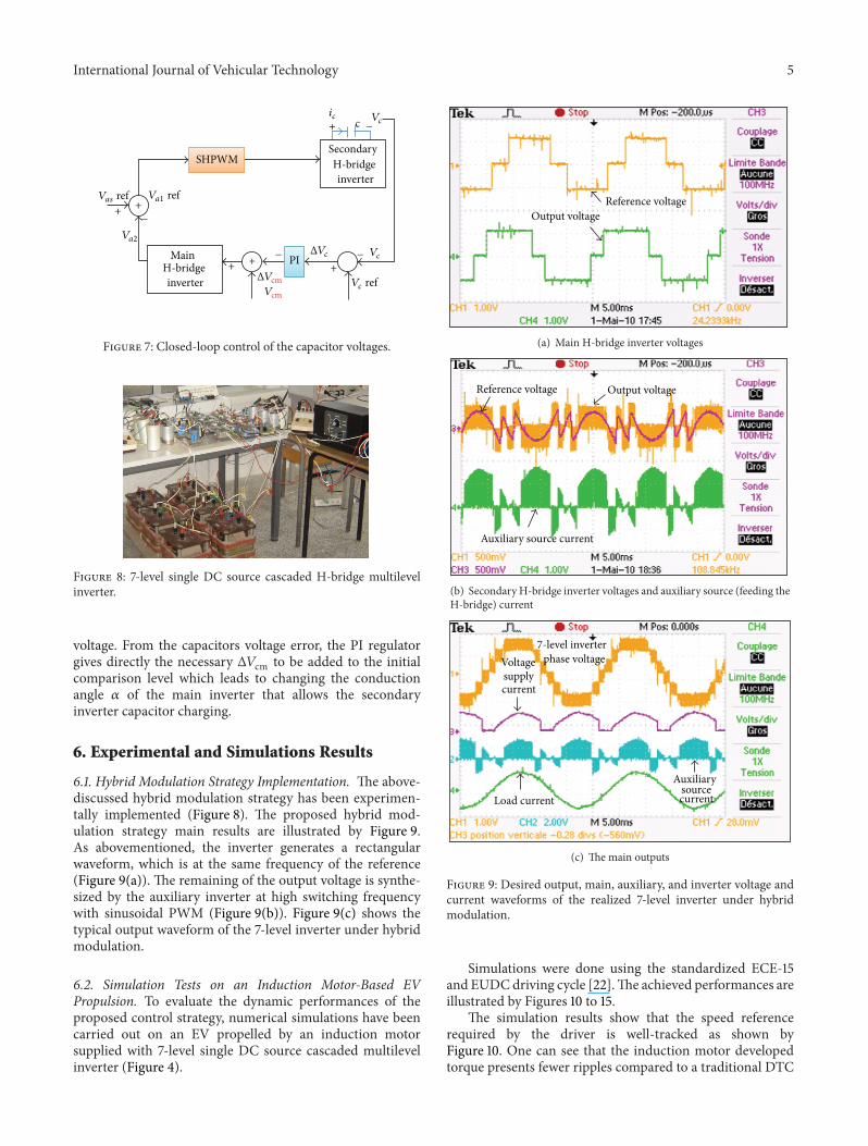
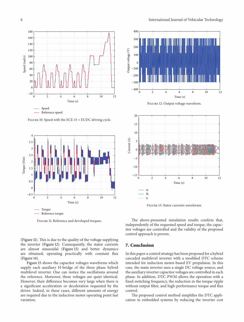
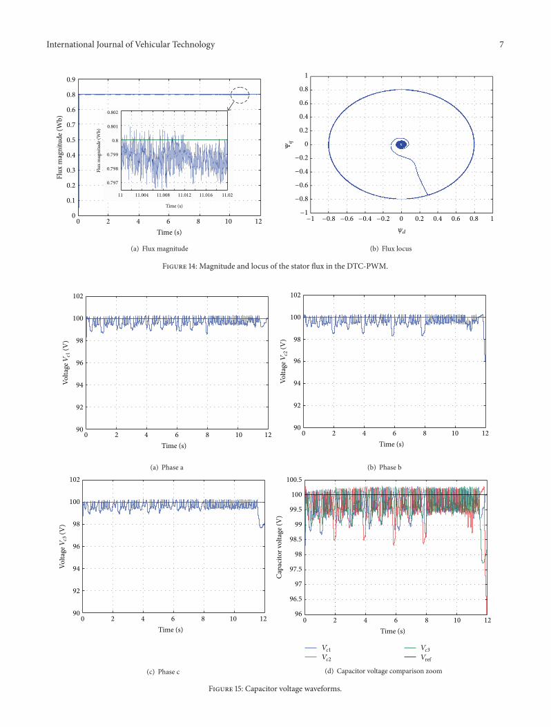
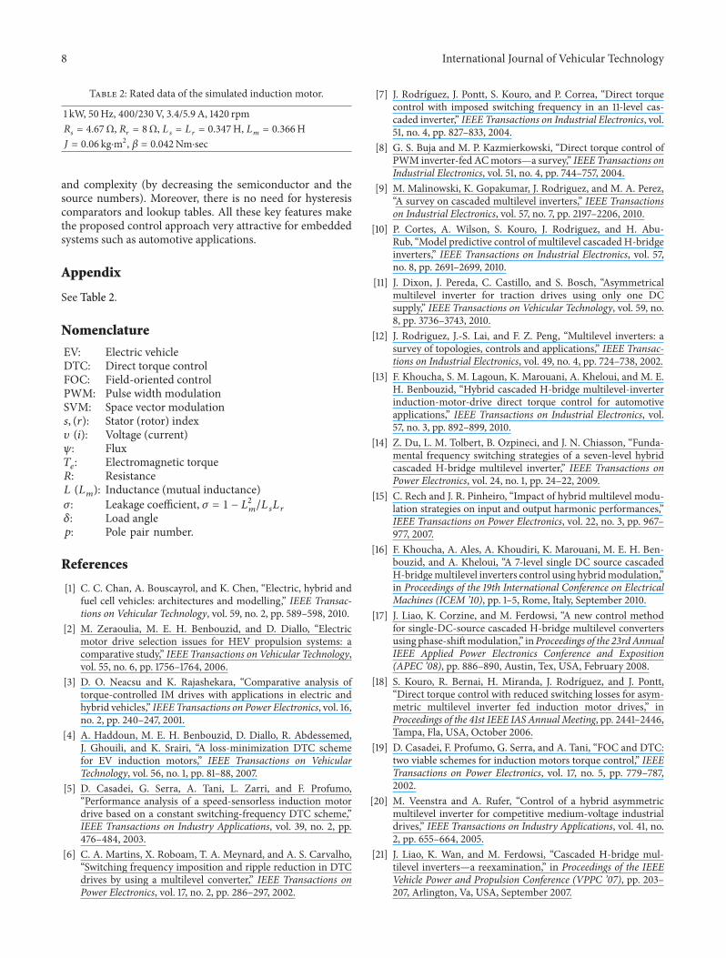

International Journal of Vehicular Technology 9
[22] A Haddoun M E H Benbouzid D Diallo R Abdessemed JGhouili and K Srairi ldquoModeling analysis and neural networkcontrol of an EV electrical differentialrdquo IEEE Transactions onIndustrial Electronics vol 55 no 6 pp 2286ndash2294 2008
Related Documents