* Corresponding authors: Ido Sliverman ( [email protected]), Michael Paul ([email protected]) Deceased A 50 kW Liquid-Lithium Target for BNCT and Material-Science Applications Michael Paul 1,* , Ido Silverman 2,* , Shlomi Halfon 2 , Semion Sukoriansky 3 , Boris Mikhailovich 3 , Tala Palchan 1 , Arkady Kapusta 3 , Arthur Shoihet 4 , Daniel Kijel 2 , Alexander Arenshtam 2, and Eli Barami 2,3 1 Racah Institute of Physics, Hebrew University, Jerusalem, Israel 91904 2 Soreq Nuclear Research Center, Yavne, Israel 81800 3 Department of Mechanical Engineering, Ben-Gurion University of the Negev, Beer-Sheva, Israel 4 NRCN, Beer-Sheva, Israel Abstract. A compact Liquid Lithium Target (LiLiT) has been operating at SARAF for several years with beam power of several kW (1.9-2.5 MeV, up to 2 mA). When bombarding the lithium with low energy protons neutrons are generated. The neutron source, mainly used for nuclear astrophysics research, was decommissioned in 2016 towards an upgraded model - with possible applications to Boron Neutron Capture Therapy (BNCT) and material-science studies. The improved version has been designed to sustain 50 kW proton beam power (2.5 MeV, ~20 mA) to provide sufficient neutron flux required for clinical BNCT application. The new model has a 50 mm wide lithium jet to enable dissipation of the higher beam power and an improved heat exchanger to remove the power to a secondary cooling loop. A new Annular Linear INduction electro-magnetic pump (ALIN) has been designed and built to provide the required lithium flow rate. Other mechanical improvements facilitate the maintenance of the system and the robustness of operation. Radiological risks due to the 7Be produced in the reaction are reduced by using an integrated lead shielding of the lithium reservoir. An integrated neutron moderator is being designed to adjust the neutron energy to the spectrum best suited to BNCT. A low power (6 kW) model of the new design with a narrower nozzle (18 mm wide) and a rotating-magnet electro-magnetic pump is operating at SARAF to support the ongoing astrophysics and nuclear research program [1], [2]. To fulfill clinical BNCT, the upgraded LiLiT model will require an accelerator of appropriate energy and intensity. The design features of the new system are presented in this paper. 1 Background Neutrons, penetrating non-ionizing particles, can be utilized in a form of radiotherapy generally termed today Neutron Capture Therapy (NCT). NCT was first suggested by G. L. Locher [3] as early as 1936, a few years only after the discovery of the neutron by J. Chadwick [4]. It is based on the radiological effects of radiations emitted following the in-situ neutron capture on a suitable nucleus. The target nucleus is best selected so that the capture results in energetic charged particles, which have a short range in tissues and a high specific energy loss (dE/dx) for maximal biological local damage. A high thermal neutron cross section and minimal residual activity are also important criteria in the selection of the target nucleus. The availability of 10 B, a stable isotope of boron, following the rich medical literature developed on the toxicology of boron and a large cross section of 3840 barns of the 10 B(n,) 7 Li reaction for thermal neutrons have made this nuclide appropriate in the modality called Boron Neutron Capture Therapy (BNCT). On absorption of a thermal neutron by 10 B, the excited 11 B nucleus promptly (~ 10-12 s) decays to two charged particles ( and 7 Li) accompanied with high probability by a 478 keV -ray. The emitted charged particles and 7 Li sharing a total energy of 2.31 MeV (1.47 MeV and 0.84 MeV, respectively) are highly-ionizing particles with short range in organic matter (~ 9 m and ~5 m, respectively) that are similar to the size of a single cell. The implementation of Boron Neutron Capture Therapy (BNCT) as a cancer radiotherapy requires an intense and practicable source of low energy (epithermal) neutrons. For many years, suitable neutron sources for BNCT were constrained to nuclear reactors. A reactor can produce a sufficient neutron flux (estimated to ~10 9 n/cm 2 /s [5]) at an irradiation facility beam port for therapy duration of 30-90 min (see [6]) but suffers significant drawbacks in suitability and availability. Worldwide efforts to design an accelerator-based neutron converter have focused on the use of lithium through the reaction 7 Li(p,n) 7 Be [7–13] at proton energies of 1.9-2.8 MeV, which produces average neutrons energies in the range 25 - 500 keV. However, a reliable conventional lithium target working under beam power levels (~ tens kW), as considered for therapy purpose in the energy range above, proves very difficult to build because of the mechanical, chemical and thermal properties of lithium (principally its low melting point at UCANS-8 EPJ Web of Conferences 231, 03004 (2020) https://doi.org/10.1051/epjconf/202023103004 © The Authors, published by EDP Sciences. This is an open access article distributed under the terms of the Creative Commons Attribution License 4.0 (http://creativecommons.org/licenses/by/4.0/).

Welcome message from author
This document is posted to help you gain knowledge. Please leave a comment to let me know what you think about it! Share it to your friends and learn new things together.
Transcript

* Corresponding authors: Ido Sliverman ( [email protected]), Michael Paul ([email protected])
Deceased
A 50 kW Liquid-Lithium Target for BNCT and Material-Science Applications
Michael Paul1,*, Ido Silverman2,*, Shlomi Halfon2, Semion Sukoriansky3, Boris Mikhailovich3, Tala Palchan1,
Arkady Kapusta3, Arthur Shoihet4, Daniel Kijel2, Alexander Arenshtam2, and Eli Barami2,3
1Racah Institute of Physics, Hebrew University, Jerusalem, Israel 91904 2Soreq Nuclear Research Center, Yavne, Israel 81800 3Department of Mechanical Engineering, Ben-Gurion University of the Negev, Beer-Sheva, Israel 4NRCN, Beer-Sheva, Israel
Abstract. A compact Liquid Lithium Target (LiLiT) has been operating at SARAF for several years with
beam power of several kW (1.9-2.5 MeV, up to 2 mA). When bombarding the lithium with low energy protons
neutrons are generated. The neutron source, mainly used for nuclear astrophysics research, was
decommissioned in 2016 towards an upgraded model - with possible applications to Boron Neutron Capture
Therapy (BNCT) and material-science studies. The improved version has been designed to sustain 50 kW
proton beam power (2.5 MeV, ~20 mA) to provide sufficient neutron flux required for clinical BNCT
application. The new model has a 50 mm wide lithium jet to enable dissipation of the higher beam power and
an improved heat exchanger to remove the power to a secondary cooling loop. A new Annular Linear
INduction electro-magnetic pump (ALIN) has been designed and built to provide the required lithium flow
rate. Other mechanical improvements facilitate the maintenance of the system and the robustness of operation.
Radiological risks due to the 7Be produced in the reaction are reduced by using an integrated lead shielding
of the lithium reservoir. An integrated neutron moderator is being designed to adjust the neutron energy to
the spectrum best suited to BNCT. A low power (6 kW) model of the new design with a narrower nozzle (18
mm wide) and a rotating-magnet electro-magnetic pump is operating at SARAF to support the ongoing
astrophysics and nuclear research program [1], [2]. To fulfill clinical BNCT, the upgraded LiLiT model will
require an accelerator of appropriate energy and intensity. The design features of the new system are presented
in this paper.
1 Background
Neutrons, penetrating non-ionizing particles, can be
utilized in a form of radiotherapy generally termed today
Neutron Capture Therapy (NCT). NCT was first
suggested by G. L. Locher [3] as early as 1936, a few
years only after the discovery of the neutron by J.
Chadwick [4]. It is based on the radiological effects of
radiations emitted following the in-situ neutron capture on
a suitable nucleus. The target nucleus is best selected so
that the capture results in energetic charged particles,
which have a short range in tissues and a high specific
energy loss (dE/dx) for maximal biological local damage.
A high thermal neutron cross section and minimal residual
activity are also important criteria in the selection of the
target nucleus. The availability of 10B, a stable isotope of
boron, following the rich medical literature developed on
the toxicology of boron and a large cross section of 3840
barns of the 10B(n,)7Li reaction for thermal neutrons
have made this nuclide appropriate in the modality called
Boron Neutron Capture Therapy (BNCT). On absorption
of a thermal neutron by 10B, the excited 11B nucleus
promptly (~ 10-12 s) decays to two charged particles (
and 7Li) accompanied with high probability by a 478 keV
-ray. The emitted charged particles and 7Li sharing a
total energy of 2.31 MeV (1.47 MeV and 0.84 MeV,
respectively) are highly-ionizing particles with short
range in organic matter (~ 9 m and ~5 m, respectively)
that are similar to the size of a single cell. The
implementation of Boron Neutron Capture Therapy
(BNCT) as a cancer radiotherapy requires an intense and
practicable source of low energy (epithermal) neutrons.
For many years, suitable neutron sources for BNCT were
constrained to nuclear reactors. A reactor can produce a
sufficient neutron flux (estimated to ~109 n/cm2/s [5]) at
an irradiation facility beam port for therapy duration of
30-90 min (see [6]) but suffers significant drawbacks in
suitability and availability.
Worldwide efforts to design an accelerator-based
neutron converter have focused on the use of lithium
through the reaction 7Li(p,n)7Be [7–13] at proton energies
of 1.9-2.8 MeV, which produces average neutrons
energies in the range 25 - 500 keV. However, a reliable
conventional lithium target working under beam power
levels (~ tens kW), as considered for therapy purpose in
the energy range above, proves very difficult to build
because of the mechanical, chemical and thermal
properties of lithium (principally its low melting point at
UCANS-8EPJ Web of Conferences 231, 03004 (2020) https://doi.org/10.1051/epjconf/202023103004
© The Authors, published by EDP Sciences. This is an open access article distributed under the terms of the Creative Commons Attribution License 4.0 (http://creativecommons.org/licenses/by/4.0/).

181°C). The development of the liquid-lithium target
LiLiT as a high-intensity epithermal neutron source,
operated in conjunction with the SARAF linear
accelerator has led us to investigate its application for
neutron radiotherapy [1, 14, 15].
The source strength of epithermal neutron spectrum
(0.1 eV - 10 keV) optimal for BNCT clinical use is
considered to be of the order of 109 n/cm2/s, together with
minimizing fluxes and dose rate of thermal neutrons
(causing collateral dose to surface tissue without
penetrating to a deep-seated tumor) and of fast neutrons
(causing collateral dose to healthy tissue through knock-
out protons). A beam-shaping assembly is therefore
necessary for the tailoring of the 7Li(p,n) neutrons to an
optimal spectrum, together with a shield for reducing the
accompanying gamma dose. In order to respond to these
demands, it is estimated that the proton beam power on
the lithium target must be of the order of 30-50 kW for
proton energy in the range 1.91-2.5 MeV.
The present project was aimed at the design and
realization of a high-power liquid-lithium target
compatible with the neutron fluxes required for BNCT, as
far as both spectrum and intensity are concerned.
2 Thermal and mechanical design of the system
2.1. Heat transfer calculations
Heat transfer calculations of the Boron Neutron Capture
Therapy (BNCT) target were performed using the
commercial ANSYS-Fluent 17.2 software. The current
simulations concentrated on the mitigation of the
excessive evaporation risk. In order to examine the
required velocity, enabling safe operation of the system,
the inlet velocity and the values of the beam power were
varied in the range of 1-20 m/s and 5-50 kW, and the
temperatures and evaporation rates were examined for
these conditions. A laminar solver was employed to solve
the Navier-Stokes equations together with the energy
equation for heat computations. Solving the equation with
the assumption of a laminar flow is the worst case in terms
of temperature analysis as turbulence enhances heat
transfer in the fluid. Figure 1 presents the estimated mass
evaporation rate as a function of lithium velocity and
beam power. These results are for a 50 mm wide nozzle
and gaussian beam parameters of x = 8 mm and y = 12
mm, which have been chosen from mechanical and
neutronic considerations. Acceptable conditions
regarding evaporation rate, up to 10 mg/h (established
according to the experience with the original LiLiT
system), are below the double black line. Based on these
simulations, it was found that the system will be able to
dissipate ~30 kW proton beam with lithium jet velocity of
~6 m/s which was achieved with the original LiLiT
system. For 50 kW beam power a 13 m/s lithium jet
velocity is required to maintain evaporation below ~10
mg/h. It will be available with the system upgraded design
describe hereby. The lithium jet thickness was set to 1.5
mm, well above the stopping range of 2.5 MeV protons.
Fig. 1. Mass evaporation rate as a function of lithium velocity
and beam power, for a gaussian beam parameters of x = 8 mm
and y = 12 mm. Acceptable conditions regarding evaporation
rate are below the double black line (evaporation rate below 10
mg/h). A more conservative operation limit of 1 mg/h is marked
by a single black line
2.2 System final design and fabrication
The liquid-lithium nozzle, a critical component in the
system, has been designed based on water experimental
simulations, since water flow at 20°C and lithium flow at
225°C have almost identical Reynolds numbers. A water
loop for the water simulation experiments was designed
and built (Figure 2a) to create water flow velocities up to
20 m/s through the nozzle.
Fig. 2. a) A water loop for the nozzle design water simulation
experiments; b) a preliminary wide nozzle design; c) wide
nozzle during water experiments (water piles up below the
nozzle at a velocity of ~10 m/s)
A preliminary wide nozzle was designed (Figure 2b)
and a plastic model of the nozzle was built and tested in
water flow simulation system (Figure 2c). A stable water
film with a smooth surface was created when the jet
velocity was below 10 m/s. At velocities above ~10 m/s
(above ~0.75 l/s) water was seen piled up downstream the
nozzle (Figure 2c), probably due to a bottleneck in the
flow exit back to the 1'' pipe. The final design has a 2"
outlet pipe to provide enough through put for the low
velocity return flow.
The 50 mm wide lithium nozzle optimized for high
power but small source size has been designed based on
a b c
UCANS-8EPJ Web of Conferences 231, 03004 (2020) https://doi.org/10.1051/epjconf/202023103004
2

the results of these water tests. The new design (see Figure
3) features an improvement in system maintenance by
providing a method to replace the nozzle without
changing the whole irradiation chamber and providing a
backup method of heating the nozzle with internal heaters.
The new design also features a method to deal with
accidental lithium spillage into the irradiation chamber
which had been an operating issue with the original
design.
In addition, a revised version of the lithium heat-
exchanger (HX) has been completed and produced. The
new HX is designed to provide higher cooling rate, better
response to thermal cycles and to reduce the risks of oil
leak from the cooling loop, with long helical oil tubes and
minimum welded joints. It also contains two connecting
ports for electromagnetic pumps (EMP), one for the
original rotating magnets EMP type at the middle of the
HX height and a second at the bottom to connect to the
new Annular Linear INduction (ALIN) type pump being
commissioned. The new design also provides a method
for lithium replacement. It is presented in Figure 4.
Fig. 3. The final design of the full power wide nozzle and the
nozzle chamber
Fig. 4. on the left, a model of the revised full power version of
the lithium heat exchanger, and at the right side a picture of the
internal part before final welding
2.3 The ALIN pump design
For this project we reconsidered our choice of EMP
lithium pump. The BNCT system requires a highly
reliable, low-maintenance and efficient device (pump) for
providing continuous circulation of liquid Li in the LiLiT
system. The pump must be hermetically sealed and
capable to work uninterruptedly for a long time without
leaks, at high temperature and in contact with radioactive
and chemically aggressive material. Mechanical pumps -
centrifugal or positive displacement - were rejected as
unable to satisfy the above requirements. An induction
magneto-hydrodynamics (MHD) pump was eventually
selected.
Based on the thermal design, the following pumping
parameters were specified for the nominal working point
(at maximal pump efficiency): volumetric flow rate Q =
2×10⁻³ m3/s, pumping pressure P = 2 bar.
Three possible MHD pump types were considered:
1. Helical induction pump driven by fast rotating
permanent magnets
2. Annular Linear Induction pump driven by 3-
phase AC magnetic system (ALIN type)
3. Helical Induction pump driven by 3-phase AC
magnetic system (HIP type)
Type 1 pump, having a rotating part, has been
evaluated as requiring more maintenance than the
induction types and hence as a possible cause of higher
radiation dose exposure for the operating staff.
Reduced scale laboratory helical pump driven by AC
inductor (HIP) was built and tested in the BGU MHD
laboratory. The pump was designed and built for use with
an existing laboratory 3-phase inductor of rotating
magnetic field. The laboratory inductor could generate
relatively weak magnetic field (up to 50 mT), such that
the estimated pumping pressure was limited to 0.5 bar.
The pump successfully produced the design pressure.
However, the experiment revealed an inherent weakness
of this design – high friction losses in the multi-turn
helical channel.
A numerical code was developed for computation of
the pump geometric, hydraulic and electric parameters.
Some of the selected design parameters for the two ALIN
pumps built (the prototype laboratory version and the final
BNCT system version) are given in Table 1.
Table 1. Design and tested parameters of the two ALIN pumps
Parmeter Symbol Units Value
Lab. pump
BNCT pump
Total pump diameter Dmax m 0.35 0.378 Total pump length Lmax m 0.72 0.72 Length of active zone of the inductor
La m 0.684 0.684
External diameter of the annular channel
Dc mm 82 112
Annular channel gap Δ mm 3 4 Diameter of ferromagnetic core
dfc mm 67 100
Number of electric coils Nc 18 24 Magnetic field in the channel gap
B T 0.167 0.247
Diameter of the coil wire DW mm 3 2.76 Number of wire windings in a bundle
NW - 70 36
Mean LM flow velocity V m/s 2.73 3 Synchronic velocity of magnetic field
VS m/s 11.4 8.4
Mean slip S = 1-V/VS 0.76 0.64 Electric current in a phase I A 18 40 Magnetomotive force MMF A·turns 7560 11520 Total active electric power WE W 3495 8350 Hydraulic efficiency of the pump
% 14 17
Conceptual representation of the ALIN type pump is
shown on Figure 5. Linear induction pumps use a
traveling magnetic field wave created by 3-phase currents.
The induced azimuthal currents and the radial component
of the traveling magnetic field generate a Lorentz force
pushing the liquid metal along the channel annulus. The
three-phase winding arrangement for the solenoids
usually follows the sequence AA ZZ BB XX CC YY
UCANS-8EPJ Web of Conferences 231, 03004 (2020) https://doi.org/10.1051/epjconf/202023103004
3
where A, B, C denote the balanced three-phase winding
and X, Y, Z the opposite phase.
In order to test the new pump design, a low
temperature version of the pump operating with Galinstan
(Ga-In-Sn, liquid metal at >16°C) alloy was built and
tested before the final high temperature version operating
with liquid Lithium was built. Experimental circuit
equipped with control valves, Venturi flow-meter,
electronic pressure transmitters, three-phase transformer
with variable voltage supply, programmable variable
frequency power supply, frequency converter and gauss-
meter for measurements of magnetic field induction was
built to test the performances of this pump. The liquid
metal flow-rate and pump pressure were measured at
different electrical currents and frequencies. At any given
set of electrical parameters, the flow rate is controlled by
closing/opening control valve. The prototype pump was
tested with two possible 3-phase connections – “star” and
“delta”. The characteristic Pressure-Flow rate curves at 50
Hz with “star” phase connections are shown on Figure 6.
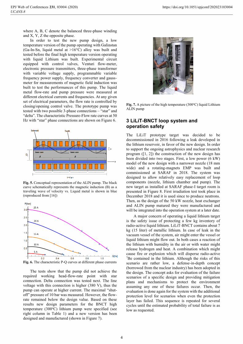
Fig. 5. Conceptual representation of the ALIN pump. The black
curve schematically represents the magnetic induction (B) as a
traveling wave of velocity vs. Liquid metal is shown in blue
(reproduced from [16])
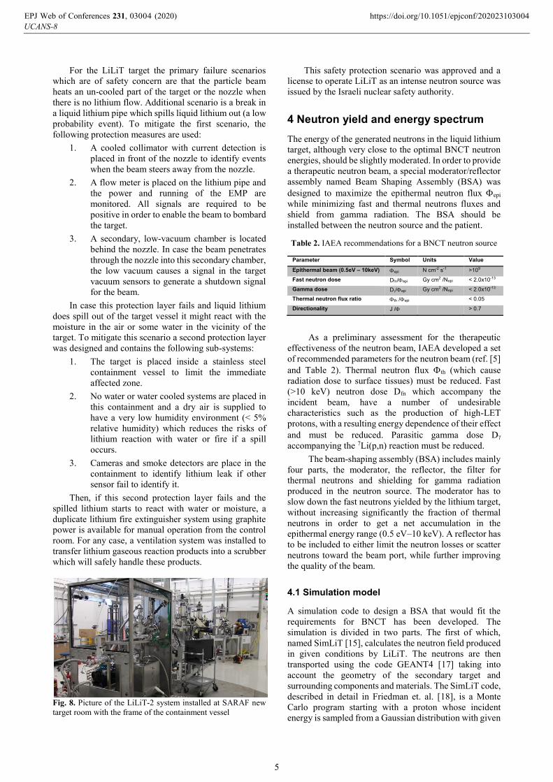
Fig. 6. The characteristic P-Q curves at different phase currents
The tests show that the pump did not achieve the
required working head-flow-rate point with star
connection. Delta connection was tested next. The line
voltage with this connection is higher (380 V), thus the
pump can operate at higher current. The maximal “shut-
off” pressure of 10 bar was measured. However, the flow-
rate remained below the design value. Based on these
results new design parameters for the BNCT high
temperature (300oC) lithium pump were specified (see
right column in Table 1) and a new version has been
designed and manufactured (shown in Figure 7).
Fig. 7. A picture of the high temperature (300oC) liquid Lithium
ALIN pump
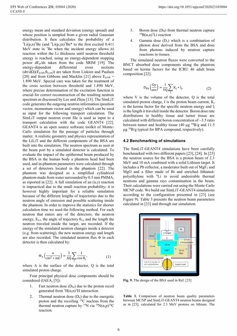
3 LiLiT-BNCT loop system and operation safety
The LiLiT prototype target was decided to be
decommissioned in 2016 following a leak developed in
the lithium reservoir, in favor of the new design. In order
to support the ongoing astrophysics and nuclear research
program ([1, 2]) the construction of the new design has
been divided into two stages. First, a low power (6 kW)
model of the new design with a narrower nozzle (18 mm
wide) and a rotating-magnets EMP was built and
commissioned at SARAF in 2018. The system was
designed to allow relatively easy replacement of loop
components (nozzle, lithium chamber and pump). The
new target as installed at SARAF phase-I target room is
presented in Figure 8. First irradiation test took place in
December 2018 and it is used since to produce neutrons.
Then, as the design of the 50 kW nozzle, heat exchanger
and ALIN pump matured they were manufactured and
will be integrated into the operation system at a later date.
A major concern of operating a liquid lithium target
is the safety issue of protecting a few kg inventory of
radio-active liquid lithium. LiLiT-BNCT contains about 7
kg (15 liter) of metallic lithium. In case of leak in the
vacuum vessel of the system, air might enter the vessel or
liquid lithium might flow out. In both cases a reaction of
the lithium with humidity in the air or with water might
release hydrogen and heat. A combination which might
cause fire or explosion which will disperse radio-active 7Be contained in the lithium. Although the risks of this
scenario are rather low, a defense-in-depth concept
(borrowed from the nuclear industry) has been adopted in
the design. The concept asks for evaluation of the failure
scenarios of a specific design and providing mitigation
plans and mechanisms to protect the environment
assuming any one of these failures occur. Then, the
evaluation is done again for the system with the additional
protection level for scenarios when even the protection
layer has failed. This sequence is repeated for several
cycles until the estimated probability of total failure is as
low as requested.
UCANS-8EPJ Web of Conferences 231, 03004 (2020) https://doi.org/10.1051/epjconf/202023103004
4
For the LiLiT target the primary failure scenarios
which are of safety concern are that the particle beam
heats an un-cooled part of the target or the nozzle when
there is no lithium flow. Additional scenario is a break in
a liquid lithium pipe which spills liquid lithium out (a low
probability event). To mitigate the first scenario, the
following protection measures are used:
1. A cooled collimator with current detection is
placed in front of the nozzle to identify events
when the beam steers away from the nozzle.
2. A flow meter is placed on the lithium pipe and
the power and running of the EMP are
monitored. All signals are required to be
positive in order to enable the beam to bombard
the target.
3. A secondary, low-vacuum chamber is located
behind the nozzle. In case the beam penetrates
through the nozzle into this secondary chamber,
the low vacuum causes a signal in the target
vacuum sensors to generate a shutdown signal
for the beam.
In case this protection layer fails and liquid lithium
does spill out of the target vessel it might react with the
moisture in the air or some water in the vicinity of the
target. To mitigate this scenario a second protection layer
was designed and contains the following sub-systems:
1. The target is placed inside a stainless steel
containment vessel to limit the immediate
affected zone.
2. No water or water cooled systems are placed in
this containment and a dry air is supplied to
have a very low humidity environment (< 5%
relative humidity) which reduces the risks of
lithium reaction with water or fire if a spill
occurs.
3. Cameras and smoke detectors are place in the
containment to identify lithium leak if other
sensor fail to identify it.
Then, if this second protection layer fails and the
spilled lithium starts to react with water or moisture, a
duplicate lithium fire extinguisher system using graphite
power is available for manual operation from the control
room. For any case, a ventilation system was installed to
transfer lithium gaseous reaction products into a scrubber
which will safely handle these products.
Fig. 8. Picture of the LiLiT-2 system installed at SARAF new
target room with the frame of the containment vessel
This safety protection scenario was approved and a
license to operate LiLiT as an intense neutron source was
issued by the Israeli nuclear safety authority.
4 Neutron yield and energy spectrum
The energy of the generated neutrons in the liquid lithium
target, although very close to the optimal BNCT neutron
energies, should be slightly moderated. In order to provide
a therapeutic neutron beam, a special moderator/reflector
assembly named Beam Shaping Assembly (BSA) was
designed to maximize the epithermal neutron flux epi
while minimizing fast and thermal neutrons fluxes and
shield from gamma radiation. The BSA should be
installed between the neutron source and the patient.
Table 2. IAEA recommendations for a BNCT neutron source
Parameter Symbol Units Value
Epithermal beam (0.5eV – 10keV) epi N cm-2 s-1 >109
Fast neutron dose Dfn/epi Gy cm2 /Nepi < 2.0x10⁻¹³
Gamma dose D/epi Gy cm2 /Nepi < 2.0x10⁻¹³
Thermal neutron flux ratio th /epi < 0.05
Directionality J / > 0.7
As a preliminary assessment for the therapeutic
effectiveness of the neutron beam, IAEA developed a set
of recommended parameters for the neutron beam (ref. [5]
and Table 2). Thermal neutron flux th (which cause
radiation dose to surface tissues) must be reduced. Fast
(>10 keV) neutron dose Dfn which accompany the
incident beam, have a number of undesirable
characteristics such as the production of high-LET
protons, with a resulting energy dependence of their effect
and must be reduced. Parasitic gamma dose D
accompanying the 7Li(p,n) reaction must be reduced.
The beam-shaping assembly (BSA) includes mainly
four parts, the moderator, the reflector, the filter for
thermal neutrons and shielding for gamma radiation
produced in the neutron source. The moderator has to
slow down the fast neutrons yielded by the lithium target,
without increasing significantly the fraction of thermal
neutrons in order to get a net accumulation in the
epithermal energy range (0.5 eV–10 keV). A reflector has
to be included to either limit the neutron losses or scatter
neutrons toward the beam port, while further improving
the quality of the beam.
4.1 Simulation model
A simulation code to design a BSA that would fit the
requirements for BNCT has been developed. The
simulation is divided in two parts. The first of which,
named SimLiT [15], calculates the neutron field produced
in given conditions by LiLiT. The neutrons are then
transported using the code GEANT4 [17] taking into
account the geometry of the secondary target and
surrounding components and materials. The SimLiT code,
described in detail in Friedman et. al. [18], is a Monte
Carlo program starting with a proton whose incident
energy is sampled from a Gaussian distribution with given
UCANS-8EPJ Web of Conferences 231, 03004 (2020) https://doi.org/10.1051/epjconf/202023103004
5
energy mean and standard deviation (energy spread) and
whose position is sampled from a given radial Gaussian
distribution. It then calculates the probability of a 7Li(p,n)7Be (and 7Li(p,n)7Be* to the first excited 0.411
MeV state in 7Be when the incident energy allows it)
reaction within the Li thickness until neutron threshold
energy is reached, using an energy-dependent stopping
power dEp/dx taken from the code SRIM [19]. The
energy-dependent differential cross sections
(dσ/dΩ)(Ep,lab,θn,cm)) are taken from Liskien and Paulsen
[20] and from Gibbons and Macklin [21] above Ep,lab =
1.890 MeV. Special care was taken for the treatment of
the cross section between threshold and 1.890 MeV,
where precise determination of the excitation function is
crucial for correct reconstruction of the resulting neutron
spectrum as discussed by Lee and Zhou [13]. The SimLiT
code generates the outgoing neutron information (position
vector, momentum vector and energy) which can be used
as input for the following transport calculation. The
SimLiT output neutron event file is used as input to a
transport calculation with the code GEANT4 [22].
GEANT4 is an open source software toolkit of Monte-
Carlo simulation for the passage of particles through
matter. A realistic geometry and physics representation of
the LiLiT and the different components of the BSA are
built into the simulation. The neutron spectrum as seen at
the beam port by a simulated detector is calculated. To
evaluate the impact of the epithermal beam produced by
the BSA in the human body a phantom head had been
used, and in-phantom parameters were calculated through
a set of detectors located in the phantom [22]. The
phantom was designed as a simplified cylindrical
phantom made from water surrounded by 0.5 mm PMMA,
as reported in [22]. A full simulation of an (n,γ) reaction
is impractical due to the small reaction probability; it is
however highly important for a reliable simulation
because of the different lengths of trajectories due to the
neutron angle of emission and possible scattering inside
the phantom. In order to improve the statistics for shorter
calculation time we used the following method. For each
neutron that enters any of the detectors, the neutron
energy, En,i, the angle of trajectory n,j and the length the
neutron traveled inside the target, are recorded. If the
energy of the simulated neutron changes inside a detector
(e.g. from scattering), the new neutron energy and length
are also recorded. The simulated neutron flux in each
detector is then calculated by:
n (n
cm2 ∗ mC) =
1
AQ∑
1
cos θj,
j
(1)
where A is the surface of the detector, Q is the total
simulated proton charge.
Four principal physical dose components should be
considered (IAEA, [5]):
1. Fast neutron dose (Dfn) due to the proton recoil
generated from 1H(n,n)1H interaction.
2. Thermal neutron dose (Dn) due to the energetic
proton and the recoiling 14C nucleus from the
thermal neutron capture by 14N via 14N(n,p)14C
reaction.
3. Boron dose (DB) from thermal neutron capture 10B(n,α)7Li reaction
4. Gamma dose (Dγ) which is a combination of
photon dose derived from the BSA and dose
from photons induced by neutron capture
reactions in tissues.
The simulated neutron fluxes were converted to the
BNCT absorbed dose components along the phantom
based on kerma factors for the ICRU 46 adult brain
composition [22].
DEn (Gy
sec) =
I
VQ∑ Kj ∗ lj
j
, (2)
where V is the volume of the detector, Q is the total
simulated proton charge, I is the proton beam current, Kj
is the kerma factor for the specific neutron energy and lj
is the length it traveled inside the detector. Boron dose rate
distributions in healthy tissue and tumor tissue are
calculated with different boron concentration of ~3.5 ratio
between tumor and healthy tissue (40 μg 10B/g and 11.5
μg 10B/g typical for BPA compound, respectively).
4.2 Benchmarking of simulations
The SimLiT-GEANT4 simulations have been carefully
benchmarked with two different papers [23], [24]. In [23]
the neutron source for the BSA is a proton beam of 2.3
MeV and 10 mA combined with a solid Lithium target. It
includes a Pb reflector, a moderator built out of MgF2 and
MgO and a filter made of Bi and enriched lithiated-
polyethylene with 6Li to avoid undesirable thermal
neutrons and gamma rays contamination in the beam.
Their calculations were carried out using the Monte Carlo
MCNP code. We build our SimLiT-GEANT4 simulations
according to the configuration presented in [23] (see
Figure 9). Table 3 presents the neutron beam parameters
calculated in [23] and through our simulation.
Fig. 9. The design of the BSA used in Ref. [23]
Table 3. Comparison of neutron beam quality parameters
between MCNP and SimLiT-GEANT4 neutron beams designed
as in [23], calculated for 2.3 MeV protons on lithium. The
After renormalizing the doses in order that the maximum healthy
punctual tissue dose is 11RBE-Gy, the total tumor and healthy tissue
dose profi les have been obtained (Fig. 13). The normalization factor
corresponds to themaximum treatment time of 40 min for which a 2.77
RBE-Gy mean dose is delivered to skin with maximum punctual dose of
15.58 RBE-Gy and a mean of 3.71 RBE-Gy to healthy brain tissue.
During this time of irradiation the mean tumor dose of 56.5 RBE-Gy
with a minimum tumor dose of 52.2 RBE-Gy can be reached, while a
therapeutic ratio of tumor to normal tissue is 5.38.
Table 4 reports in-phantom parameters of different published
works.
The Fig. 14 shows longitudinal section in the head-phantom of the
deposited energy of neutrons (a) and gamma rays (b), where the red
and blue colors are representative for maximum and minimum-de-
posited energy, respectively.
Fig. 9. The final designed BSA.
Fig. 10. Neutron spectrum at beam port of the optimized BSA.
Table 3
Beam parameters of our BSA configuration and some published works.
Beam
parameters
Neutron
yield
(x1014 n/ s)
ɸepi
(x109
n/ cm2 s)
Dfn/ ɸepi
(x10–13
Gy.cm2)
Dg/ ɸepi
(x10–13
Gy.cm2)
ɸepi/
ɸthermal
J/ ɸ
IAEA criteria – (0.5–1) < 2 < 2 > 20 > 0.7
Our work 5.78E-2 1.04 1.25 1.89 29.4 0.657
(Cerullo et al.,
2002)
4 2.51 3.45 0.21 114.5 0.57
(Rasouli et al.,
2012)
1.45 4.43 0.59 1.98 121.2 0.61
(Rahmani and
Shahriari,
2011)
– 0.819 7.98 1.18 – –
Fig. 11. Neutron flux profi les in head phantom.
Fig. 12. Dose profi les in healthy tissue.
Fig. 13. Dose profi les in tumor and healthy tissue during maximum treatment
time.
L. Zaidi et al.
UCANS-8EPJ Web of Conferences 231, 03004 (2020) https://doi.org/10.1051/epjconf/202023103004
6
discrepancy in the Dfn/ɸepi values between the MCNP and
SimLiT-Geant4 simulations is under study
Model epi
[109 n/cm2/sec]
Dfn/epi
[10-13 Gy cm2]
epi/thermal J/
MCNP 1.04 1.25 29.4 0.657
SimLiT-Geant4 1.24 4.51 21 0.607
In ref. [24], two types of neutron generation
reactions have been considered. One is p-Li reaction and
the other is p-Be reaction. The p-Li reaction gives larger
number of neutrons than the p-Be reaction at low proton
energy region around 2-3 MeV, and the neutron energy is
much lower than that produced by the p-Be reaction at
higher proton energy. In their work they calculated, using
the Monte-Carlo MCNP code, several moderator
materials including fluorine, F. From these results they
decided to use the moderator materials; MgF2 for the p-Li
reaction and LiF for the p-Be reaction. We choose to
benchmark the configuration of the MgF2 36 cm x 21 cm
as moderator material for the p-Li reaction. Table 4 shows
the comparison of the values required for the BNCT
system.
Table 4. Calculated values for neutron epithermal flux, ratio of
fast to epithermal neutrons and thermal flux for a 7Li(p,n) setup
after moderation [24]. The Table compares values calculated
with two main established transport codes (MCNP, GEANT4).
Model epi
[n/cm2/sec/mA]
Dfn/epi
[Gy cm2]
thermal
MCNP 2.79*107 1.0*10-12 3.29*103
SimLiT-Geant4 4.51*107 8.9*10-13 2.31*104
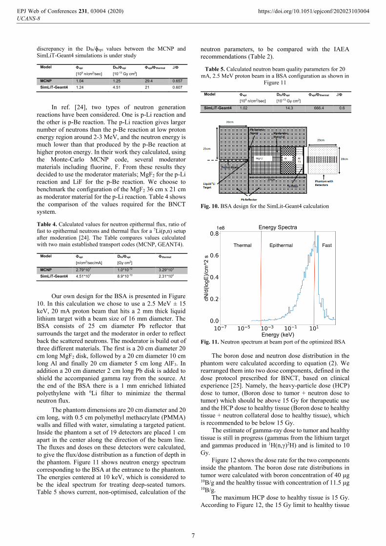
Our own design for the BSA is presented in Figure
10. In this calculation we chose to use a 2.5 MeV ± 15
keV, 20 mA proton beam that hits a 2 mm thick liquid
lithium target with a beam size of 16 mm diameter. The
BSA consists of 25 cm diameter Pb reflector that
surrounds the target and the moderator in order to reflect
back the scattered neutrons. The moderator is build out of
three different materials. The first is a 20 cm diameter 20
cm long MgF2 disk, followed by a 20 cm diameter 10 cm
long Al and finally 20 cm diameter 5 cm long AlF3. In
addition a 20 cm diameter 2 cm long Pb disk is added to
shield the accompanied gamma ray from the source. At
the end of the BSA there is a 1 mm enriched lithiated
polyethylene with 6Li filter to minimize the thermal
neutron flux.
The phantom dimensions are 20 cm diameter and 20
cm long, with 0.5 cm polymethyl methacrylate (PMMA)
walls and filled with water, simulating a targeted patient.
Inside the phantom a set of 19 detectors are placed 1 cm
apart in the center along the direction of the beam line.
The fluxes and doses on these detectors were calculated,
to give the flux/dose distribution as a function of depth in
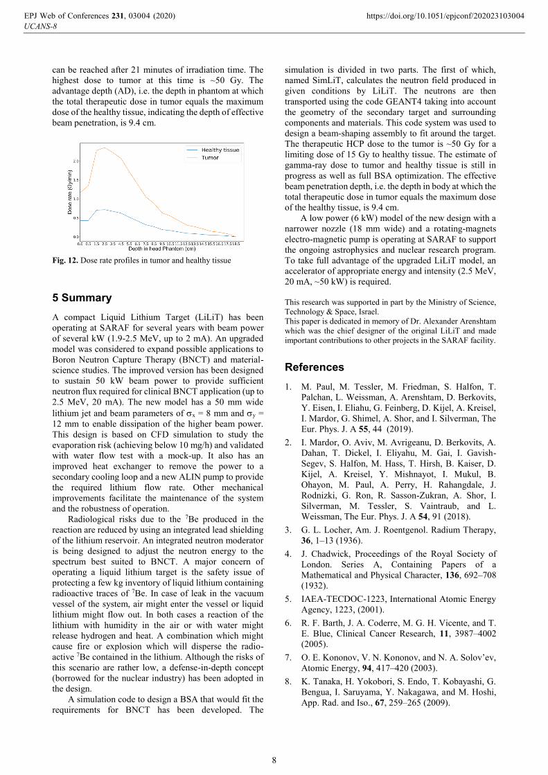
the phantom. Figure 11 shows neutron energy spectrum
corresponding to the BSA at the entrance to the phantom.
The energies centered at 10 keV, which is considered to
be the ideal spectrum for treating deep-seated tumors.
Table 5 shows current, non-optimised, calculation of the
neutron parameters, to be compared with the IAEA
recommendations (Table 2).
Table 5. Calculated neutron beam quality parameters for 20
mA, 2.5 MeV proton beam in a BSA configuration as shown in
Figure 11
Model epi
[109 n/cm2/sec]
Dfn/epi
[10-13 Gy cm2]
epi/thermal J/
SimLiT-Geant4 1.02 14.3 666.4 0.6
Fig. 10. BSA design for the SimLit-Geant4 calculation
Fig. 11. Neutron spectrum at beam port of the optimized BSA
The boron dose and neutron dose distribution in the
phantom were calculated according to equation (2). We
rearranged them into two dose components, defined in the
dose protocol prescribed for BNCT, based on clinical
experience [25]. Namely, the heavy-particle dose (HCP)
dose to tumor, (Boron dose to tumor + neutron dose to
tumor) which should be above 15 Gy for therapeutic use
and the HCP dose to healthy tissue (Boron dose to healthy
tissue + neutron collateral dose to healthy tissue), which
is recommended to be below 15 Gy.
The estimate of gamma-ray dose to tumor and healthy
tissue is still in progress (gammas from the lithium target
and gammas produced in 1H(n,γ)2H) and is limited to 10
Gy.
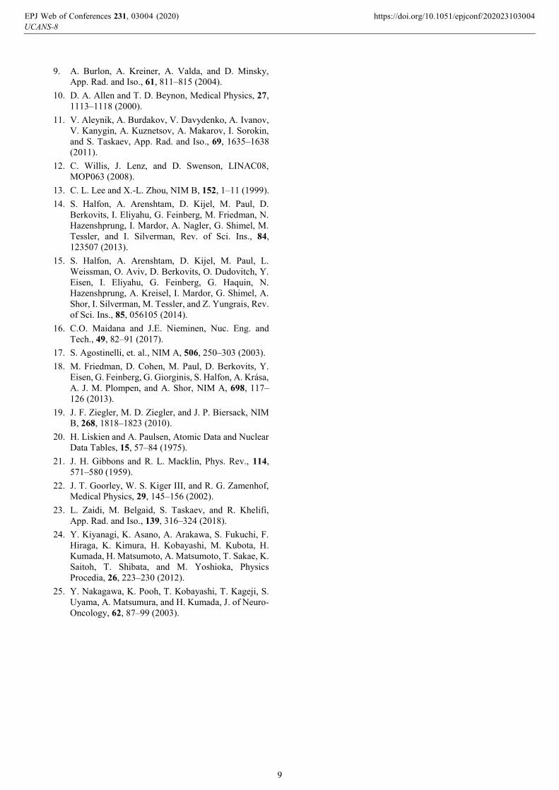
Figure 12 shows the dose rate for the two components
inside the phantom. The boron dose rate distributions in
tumor were calculated with boron concentration of 40 μg 10B/g and the healthy tissue with concentration of 11.5 μg 10B/g.
The maximum HCP dose to healthy tissue is 15 Gy.
According to Figure 12, the 15 Gy limit to healthy tissue
UCANS-8EPJ Web of Conferences 231, 03004 (2020) https://doi.org/10.1051/epjconf/202023103004
7
can be reached after 21 minutes of irradiation time. The
highest dose to tumor at this time is ~50 Gy. The
advantage depth (AD), i.e. the depth in phantom at which
the total therapeutic dose in tumor equals the maximum
dose of the healthy tissue, indicating the depth of effective
beam penetration, is 9.4 cm.
Fig. 12. Dose rate profiles in tumor and healthy tissue
5 Summary
A compact Liquid Lithium Target (LiLiT) has been
operating at SARAF for several years with beam power
of several kW (1.9-2.5 MeV, up to 2 mA). An upgraded
model was considered to expand possible applications to
Boron Neutron Capture Therapy (BNCT) and material-
science studies. The improved version has been designed
to sustain 50 kW beam power to provide sufficient
neutron flux required for clinical BNCT application (up to
2.5 MeV, 20 mA). The new model has a 50 mm wide
lithium jet and beam parameters of x = 8 mm and y =
12 mm to enable dissipation of the higher beam power.
This design is based on CFD simulation to study the
evaporation risk (achieving below 10 mg/h) and validated
with water flow test with a mock-up. It also has an
improved heat exchanger to remove the power to a
secondary cooling loop and a new ALIN pump to provide
the required lithium flow rate. Other mechanical
improvements facilitate the maintenance of the system
and the robustness of operation.
Radiological risks due to the 7Be produced in the
reaction are reduced by using an integrated lead shielding
of the lithium reservoir. An integrated neutron moderator
is being designed to adjust the neutron energy to the
spectrum best suited to BNCT. A major concern of
operating a liquid lithium target is the safety issue of
protecting a few kg inventory of liquid lithium containing
radioactive traces of 7Be. In case of leak in the vacuum
vessel of the system, air might enter the vessel or liquid
lithium might flow out. In both cases a reaction of the
lithium with humidity in the air or with water might
release hydrogen and heat. A combination which might
cause fire or explosion which will disperse the radio-
active 7Be contained in the lithium. Although the risks of
this scenario are rather low, a defense-in-depth concept
(borrowed for the nuclear industry) has been adopted in
the design.
A simulation code to design a BSA that would fit the
requirements for BNCT has been developed. The
simulation is divided in two parts. The first of which,
named SimLiT, calculates the neutron field produced in
given conditions by LiLiT. The neutrons are then
transported using the code GEANT4 taking into account
the geometry of the secondary target and surrounding
components and materials. This code system was used to
design a beam-shaping assembly to fit around the target.
The therapeutic HCP dose to the tumor is ~50 Gy for a
limiting dose of 15 Gy to healthy tissue. The estimate of
gamma-ray dose to tumor and healthy tissue is still in
progress as well as full BSA optimization. The effective
beam penetration depth, i.e. the depth in body at which the
total therapeutic dose in tumor equals the maximum dose
of the healthy tissue, is 9.4 cm.
A low power (6 kW) model of the new design with a
narrower nozzle (18 mm wide) and a rotating-magnets
electro-magnetic pump is operating at SARAF to support
the ongoing astrophysics and nuclear research program.
To take full advantage of the upgraded LiLiT model, an
accelerator of appropriate energy and intensity (2.5 MeV,
20 mA, ~50 kW) is required.
This research was supported in part by the Ministry of Science,
Technology & Space, Israel.
This paper is dedicated in memory of Dr. Alexander Arenshtam
which was the chief designer of the original LiLiT and made
important contributions to other projects in the SARAF facility.
References
1. M. Paul, M. Tessler, M. Friedman, S. Halfon, T.
Palchan, L. Weissman, A. Arenshtam, D. Berkovits,
Y. Eisen, I. Eliahu, G. Feinberg, D. Kijel, A. Kreisel,
I. Mardor, G. Shimel, A. Shor, and I. Silverman, The
Eur. Phys. J. A 55, 44 (2019).
2. I. Mardor, O. Aviv, M. Avrigeanu, D. Berkovits, A.
Dahan, T. Dickel, I. Eliyahu, M. Gai, I. Gavish-
Segev, S. Halfon, M. Hass, T. Hirsh, B. Kaiser, D.
Kijel, A. Kreisel, Y. Mishnayot, I. Mukul, B.
Ohayon, M. Paul, A. Perry, H. Rahangdale, J.
Rodnizki, G. Ron, R. Sasson-Zukran, A. Shor, I.
Silverman, M. Tessler, S. Vaintraub, and L.
Weissman, The Eur. Phys. J. A 54, 91 (2018).
3. G. L. Locher, Am. J. Roentgenol. Radium Therapy,
36, 1–13 (1936).
4. J. Chadwick, Proceedings of the Royal Society of
London. Series A, Containing Papers of a
Mathematical and Physical Character, 136, 692–708
(1932).
5. IAEA-TECDOC-1223, International Atomic Energy
Agency, 1223, (2001).
6. R. F. Barth, J. A. Coderre, M. G. H. Vicente, and T.
E. Blue, Clinical Cancer Research, 11, 3987–4002
(2005).
7. O. E. Kononov, V. N. Kononov, and N. A. Solov’ev,
Atomic Energy, 94, 417–420 (2003).
8. K. Tanaka, H. Yokobori, S. Endo, T. Kobayashi, G.
Bengua, I. Saruyama, Y. Nakagawa, and M. Hoshi,
App. Rad. and Iso., 67, 259–265 (2009).
UCANS-8EPJ Web of Conferences 231, 03004 (2020) https://doi.org/10.1051/epjconf/202023103004
8
9. A. Burlon, A. Kreiner, A. Valda, and D. Minsky,
App. Rad. and Iso., 61, 811–815 (2004).
10. D. A. Allen and T. D. Beynon, Medical Physics, 27,
1113–1118 (2000).
11. V. Aleynik, A. Burdakov, V. Davydenko, A. Ivanov,
V. Kanygin, A. Kuznetsov, A. Makarov, I. Sorokin,
and S. Taskaev, App. Rad. and Iso., 69, 1635–1638
(2011).
12. C. Willis, J. Lenz, and D. Swenson, LINAC08,
MOP063 (2008).
13. C. L. Lee and X.-L. Zhou, NIM B, 152, 1–11 (1999).
14. S. Halfon, A. Arenshtam, D. Kijel, M. Paul, D.
Berkovits, I. Eliyahu, G. Feinberg, M. Friedman, N.
Hazenshprung, I. Mardor, A. Nagler, G. Shimel, M.
Tessler, and I. Silverman, Rev. of Sci. Ins., 84,
123507 (2013).
15. S. Halfon, A. Arenshtam, D. Kijel, M. Paul, L.
Weissman, O. Aviv, D. Berkovits, O. Dudovitch, Y.
Eisen, I. Eliyahu, G. Feinberg, G. Haquin, N.
Hazenshprung, A. Kreisel, I. Mardor, G. Shimel, A.
Shor, I. Silverman, M. Tessler, and Z. Yungrais, Rev.
of Sci. Ins., 85, 056105 (2014).
16. C.O. Maidana and J.E. Nieminen, Nuc. Eng. and
Tech., 49, 82–91 (2017).
17. S. Agostinelli, et. al., NIM A, 506, 250–303 (2003).
18. M. Friedman, D. Cohen, M. Paul, D. Berkovits, Y.
Eisen, G. Feinberg, G. Giorginis, S. Halfon, A. Krása,
A. J. M. Plompen, and A. Shor, NIM A, 698, 117–
126 (2013).
19. J. F. Ziegler, M. D. Ziegler, and J. P. Biersack, NIM
B, 268, 1818–1823 (2010).
20. H. Liskien and A. Paulsen, Atomic Data and Nuclear
Data Tables, 15, 57–84 (1975).
21. J. H. Gibbons and R. L. Macklin, Phys. Rev., 114,
571–580 (1959).
22. J. T. Goorley, W. S. Kiger III, and R. G. Zamenhof,
Medical Physics, 29, 145–156 (2002).
23. L. Zaidi, M. Belgaid, S. Taskaev, and R. Khelifi,
App. Rad. and Iso., 139, 316–324 (2018).
24. Y. Kiyanagi, K. Asano, A. Arakawa, S. Fukuchi, F.
Hiraga, K. Kimura, H. Kobayashi, M. Kubota, H.
Kumada, H. Matsumoto, A. Matsumoto, T. Sakae, K.
Saitoh, T. Shibata, and M. Yoshioka, Physics
Procedia, 26, 223–230 (2012).
25. Y. Nakagawa, K. Pooh, T. Kobayashi, T. Kageji, S.
Uyama, A. Matsumura, and H. Kumada, J. of Neuro-
Oncology, 62, 87–99 (2003).
UCANS-8EPJ Web of Conferences 231, 03004 (2020) https://doi.org/10.1051/epjconf/202023103004
9
Related Documents