International Test and Evaluation Association Test Technology Review Huntsville, Alabama November 5, 2015 Approved for Public Release; Distribution Unlimited; PA# AEDC2014-139 A-10 ANALYSIS USING THE HPCMP CREATE TM -AV KESTREL PRODUCT UTILIZING THE FIREBOLT PROPULSION COMPONENT Jason B. Klepper and Bonnie D. Heikkinen Aerospace Testing Alliance Arnold Engineering Development Complex Arnold Air Force Base, TN Robert H. Nichols University of Alabama Birmingham Arnold Engineering Development Complex Arnold Air Force Base, TN

Welcome message from author
This document is posted to help you gain knowledge. Please leave a comment to let me know what you think about it! Share it to your friends and learn new things together.
Transcript

International Test and Evaluation Association
Test Technology ReviewHuntsville, Alabama November 5, 2015
Approved for Public Release; Distribution Unlimited; PA# AEDC2014-139
A-10 ANALYSIS USING THE HPCMP CREATETM-AV KESTREL PRODUCT UTILIZING THE FIREBOLT
PROPULSION COMPONENT
Jason B. Klepper and Bonnie D. HeikkinenAerospace Testing Alliance
Arnold Engineering Development ComplexArnold Air Force Base, TN
Robert H. NicholsUniversity of Alabama Birmingham
Arnold Engineering Development ComplexArnold Air Force Base, TN

ITEA2015 TTR - 2CREATE-AV
0110010101100100010111001 Approved for Public Release; Distribution Unlimited; PA# AEDC2014-139
Background
A-10 single seat tactical aircraft
Two TF34-GE-100 high bypass
turbofans mounted above and
behind inboard section of wing
– Flow quality over the wing
must be maintained
– Distorted flow over wing likely to
be ingested by engine and cause stability issues
A-10 mission requires operation of aircraft at high AOA and AOSS
To mitigate distorted flow over wing, A-10 currently uses a movable slat on the inboard wing leading edge
To reduce maintenance cost, SPO interested in replacing movable slat with fixed geometry on wing inboard leading edge
Several candidate geometries tested on 10% scale model in AEDC 16T wind tunnel

ITEA2015 TTR - 3CREATE-AV
0110010101100100010111001 Approved for Public Release; Distribution Unlimited; PA# AEDC2014-139
Purpose/Outline
Summarize the use of CREATETM-AV Kestrel with Firebolt propulsion component in analyzing the A-10
Tunnel scale simulations– Baseline Wing
– Modified Wing
Flight scale simulations (Baseline wing only)– Using Firebolt Cap 1 (0-D engine model)
– Using Firebolt Cap 2 (full annulus turbomachinery)
Flight scale store separation simulations using Firebolt Cap 1 to simulate propulsion effects– Baseline and modified wing using all unstructured meshes
– Baseline wing using NBOB capability
Conclusions
ITEA2015 TTR - 4CREATE-AV
0110010101100100010111001 Approved for Public Release; Distribution Unlimited; PA# AEDC2014-139
CREATETM Overview
Computational Research and Engineering Acquisition Tools and Environments (CREATETM)– DOD HPCMP program to improve acquisition timeline, cost,
and performance through the use of CSE tools
– Covers ships (SHIPS), aircraft (AV), antenna design and analysis (RF), meshing (MG)
– CREATE-AV Kestrel – fixed wing
Helios – rotary wing
DaVinci – conceptual design

ITEA2015 TTR - 5CREATE-AV
0110010101100100010111001 Approved for Public Release; Distribution Unlimited; PA# AEDC2014-139
Kestrel - Firebolt Overview
Kestrel: High-fidelity simulation tool used to model aircraft flow-field behavior
Firebolt: Modular propulsion component– FB Cap 1: Low-order (0-D) steady-state or transient engine
models (cycle decks)
– FB Cap 2: High-fidelity full annulus rotating turbomachinery
Kestrel - Firebolt combination provides virtual system to simulate integrated airframe-inlet-propulsion system dynamic performance– Maneuvering aircraft
– Complex unsteady inlet distortion

ITEA2015 TTR - 6CREATE-AV
0110010101100100010111001 Approved for Public Release; Distribution Unlimited; PA# AEDC2014-139
Airframe/Inlet/Engine Integration
Historical Process
– Scale model testing of airframe and inlet in wind tunnel
– Reduce wind tunnel results to AIP distortion patterns
– Engine stability testing with distortion patterns
– First time airframe/inlet/engine are coupled is at flight test
Kestrel with Firebolt
– Enables integration of airframe/inlet/engine simulations
– Allow discovery of possible integration issues early in weapon system design cycle
– Impact weapon system development
Schedule
Cost
CFD Inlet Predictions Wind Tunnel Tests AIP Distortion Patterns Distortion Screen Tests
Flight Test Verification
1.20
1.18
1.16
1.14
1.12
1.10
1.08
1.06
1.04
1.02
1.00
0.98
0.96
0.94
0.92
0.90
Run 1603 Point 4
0.9
0
0.9
2
0.92 0.9
4
0.9
4
0.96
0.9
6
0.96
0.98
0.98
0.9
8
0.9
8
0.98
0.98
1.00
1.0
0
1.00
1.0
01.0
0
1.00
1.00
1.02
1.0
2
1.021.02
1.0
2
1.0
4
1.04
1.0
4
1.04

ITEA2015 TTR - 7CREATE-AV
0110010101100100010111001 Approved for Public Release; Distribution Unlimited; PA# AEDC2014-139
Tunnel Scale Simulations
Wind tunnel geometry (10% Scale)
– Replaceable inboard wing leading edge
– Port nacelle: flow through
– Starboard nacelle
Connected to calibrated ejector
40-probe rake with high response total pressure probes
CFD tunnel geometry (10% Scale)
– No sting or ejector body modeled
– Port nacelle: flow through
– Starboard nacelle: sink boundary condition (constant mass flow)
CFD tunnel simulations
– Mesh: 30 million cells
– HLLE+ inviscid flux scheme
– Spalart-Allmaras Delayed Detached Eddy Simulation (SA-DDES) turbulence model
– 1x10⁻⁴ sec. time step
– Typical solution: 20,000 iterations
Time-averaged over 15,000 iterations (1.5 sec)
36 hours on 512 cores
Baseline Wing with
Extended SlatModified Wing
Sink BC Flow Thru
Stall Strip
Stall Strip
ITEA2015 TTR - 8CREATE-AV
0110010101100100010111001 Approved for Public Release; Distribution Unlimited; PA# AEDC2014-139
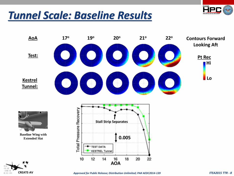
Tunnel Scale: Baseline Results
17o 19o 20o 21o 22oAoA
Test:
Contours Forward Looking Aft
HiPt Rec
KestrelTunnel:
Stall Strip Separates
0.005
AOA
Lo
Baseline Wing with
Extended Slat

ITEA2015 TTR - 9CREATE-AV
0110010101100100010111001 Approved for Public Release; Distribution Unlimited; PA# AEDC2014-139
Tunnel Scale: Modified Results
17o 18o 19o 20o 21oAoA
Test:
Contours Forward Looking Aft
HiPt Rec
KestrelTunnel:
Stall Strip Separates
0.010
AOA
Lo
Modified Wing
ITEA2015 TTR - 10CREATE-AV
0110010101100100010111001 Approved for Public Release; Distribution Unlimited; PA# AEDC2014-139
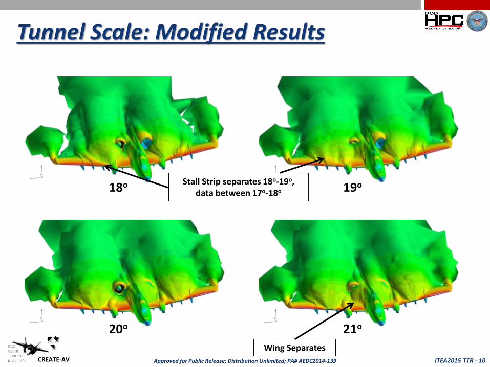
Tunnel Scale: Modified Results
Stall Strip separates 18o-19o,data between 17o-18o
Wing Separates
18o 19o
20o 21o
ITEA2015 TTR - 11CREATE-AV
0110010101100100010111001 Approved for Public Release; Distribution Unlimited; PA# AEDC2014-139
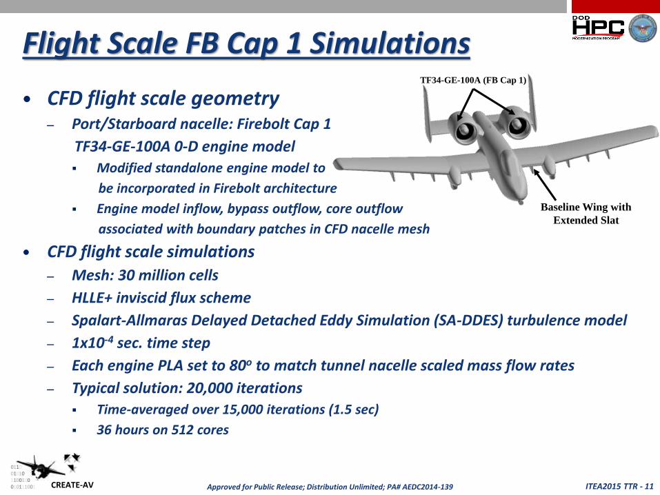
Flight Scale FB Cap 1 Simulations
CFD flight scale geometry– Port/Starboard nacelle: Firebolt Cap 1
TF34-GE-100A 0-D engine model
Modified standalone engine model to
be incorporated in Firebolt architecture
Engine model inflow, bypass outflow, core outflow
associated with boundary patches in CFD nacelle mesh
CFD flight scale simulations
– Mesh: 30 million cells
– HLLE+ inviscid flux scheme
– Spalart-Allmaras Delayed Detached Eddy Simulation (SA-DDES) turbulence model
– 1x10⁻⁴ sec. time step
– Each engine PLA set to 80o to match tunnel nacelle scaled mass flow rates
– Typical solution: 20,000 iterations
Time-averaged over 15,000 iterations (1.5 sec)
36 hours on 512 cores
TF34-GE-100A (FB Cap 1)
Baseline Wing with
Extended Slat

ITEA2015 TTR - 12CREATE-AV
0110010101100100010111001 Approved for Public Release; Distribution Unlimited; PA# AEDC2014-139
Flight Scale FB Cap 1 Results
17o 19o 20o 21o 22oAoA
Test:
Contours Forward Looking Aft
HiPt Rec
KestrelTunnel:
Stall Strip Separates
0.005
AOA
Lo
KestrelFlight:

ITEA2015 TTR - 13CREATE-AV
0110010101100100010111001 Approved for Public Release; Distribution Unlimited; PA# AEDC2014-139
Flight Scale FB Cap 2 Simulations
CFD flight scale geometry– Port Nacelle: FB Cap 1 - TF34-GE-100A 0-D engine model– Starboard Nacelle: FB Cap 2 - TF34 rotating turbomachinery fan
Core inflow/outflow boundaries set from 0-D model
CFD flight scale simulations– Mesh: 105 million cells (A-10: 30 million, TF34 Fan: 75 million)– HLLE+ inviscid flux scheme– Spalart-Allmaras Delayed Detached Eddy Simulation (SA-DDES) turbulence model– 5x10⁻⁶ sec. time step– 0-D engine PLA set to 80o
– TF34 fan set to 6500 RPM (matches 0-D engine model fan speed)
• Typical solution: ~15 rotor revolutions (720 cores)– ~10 rotor revolutions at “quasi-steady” state– 14 sec/iter, 2000 iter/revolution, 3.5 revolutions/day, 4-6 days/solutions
TF34 Fan (FB Cap 2) TF34-GE-100A (FB Cap 1)
Baseline Wing with Extended Slats
28 Rotor Blades
Bypass Duct
Core Inflow Duct
Core Inflow BC
Core Outflow BC
TF34 Fan
ITEA2015 TTR - 14CREATE-AV
0110010101100100010111001 Approved for Public Release; Distribution Unlimited; PA# AEDC2014-139
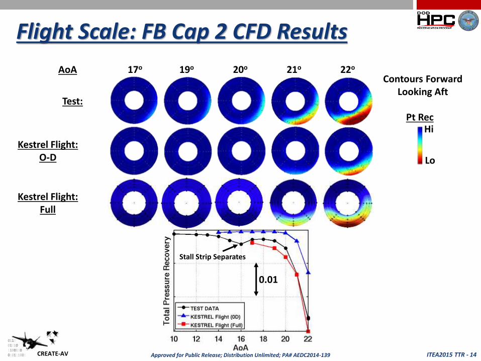
Flight Scale: FB Cap 2 CFD Results
17o 19o 20o 21o 22oAoA
Test:
Contours Forward Looking Aft
HiPt Rec
Stall Strip Separates
0.01
Lo
Kestrel Flight:O-D
Kestrel Flight:Full
ITEA2015 TTR - 15CREATE-AV
0110010101100100010111001 Approved for Public Release; Distribution Unlimited; PA# AEDC2014-139
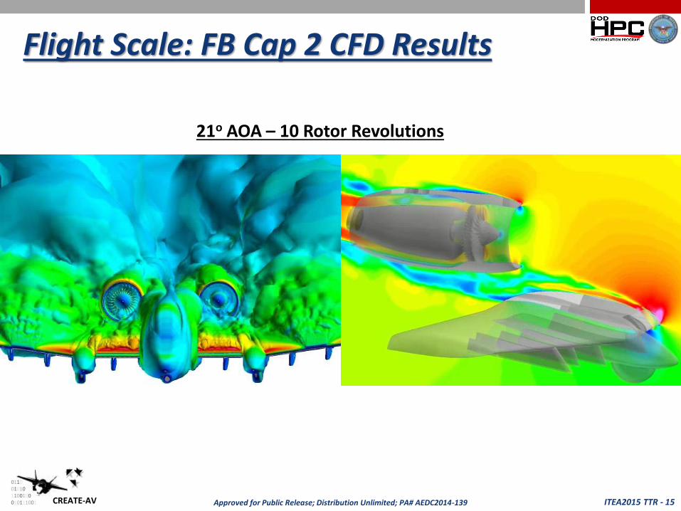
Flight Scale: FB Cap 2 CFD Results
21o AOA – 10 Rotor Revolutions
ITEA2015 TTR - 16CREATE-AV
0110010101100100010111001 Approved for Public Release; Distribution Unlimited; PA# AEDC2014-139
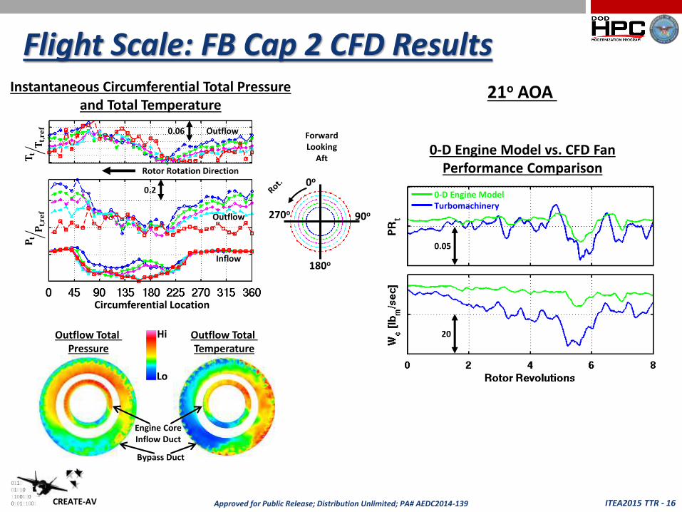
Flight Scale: FB Cap 2 CFD Results
Circumferential Location
0.2
0.06
Outflow
Inflow
0o
90o270o
ForwardLooking
Aft
Rotor Rotation Direction
Outflow
Instantaneous Circumferential Total Pressure and Total Temperature
0-D Engine ModelTurbomachinery
0.05
20
0-D Engine Model vs. CFD FanPerformance Comparison
180o
Hi
Lo
Outflow Total Pressure
Outflow Total Temperature
Engine Core Inflow Duct
Bypass Duct
൘𝐏𝐭𝐏𝐭,𝐫𝐞𝐟
൘𝐓𝐭𝐓𝐭,𝐫𝐞𝐟
21o AOA

ITEA2015 TTR - 17CREATE-AV
0110010101100100010111001 Approved for Public Release; Distribution Unlimited; PA# AEDC2014-139
Fuel Tank Store Separation Simulations
Proposed wing modification in close proximity
to several store pylons
Compare store separation characteristics for
baseline and modified wing– Empty 600-gallon fuel tank store
– Two pylons; Two separate Flight conditions
– Overset meshes and 6DOF
A-10 mesh– Slat retracted due to flight conditions of drop
– Used FB Cap 1 TF34-GE-100A 0-D engine model at 80o PLA
– Controlled unstructured volume mesh under aircraft in region of drop: 37 million cells
Empty 600-gallon fuel tank mesh– 7.5 million cells
– Included mass, moments of inertia,
CG, and forward lug ejector forces
Typical solution: 18,000 iterations– 13,000 iterations after drop (1.3 sec)
– 48 hours on 512 cores
1000
Forward Lug Ejector Forces600-gallon Fuel Tank Surface Mesh
ITEA2015 TTR - 18CREATE-AV
0110010101100100010111001 Approved for Public Release; Distribution Unlimited; PA# AEDC2014-139
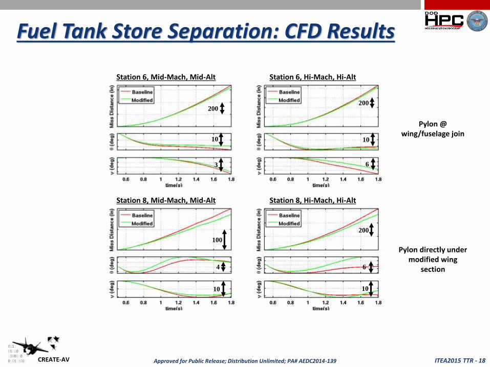
Fuel Tank Store Separation: CFD Results
Station 6, Mid-Mach, Mid-Alt Station 6, Hi-Mach, Hi-Alt
Station 8, Mid-Mach, Mid-Alt Station 8, Hi-Mach, Hi-Alt
200
10
3
200
10
6
100
4
10
200
6
10
Pylon @ wing/fuselage join
Pylon directly under modified wing
section

ITEA2015 TTR - 19CREATE-AV
0110010101100100010111001 Approved for Public Release; Distribution Unlimited; PA# AEDC2014-139
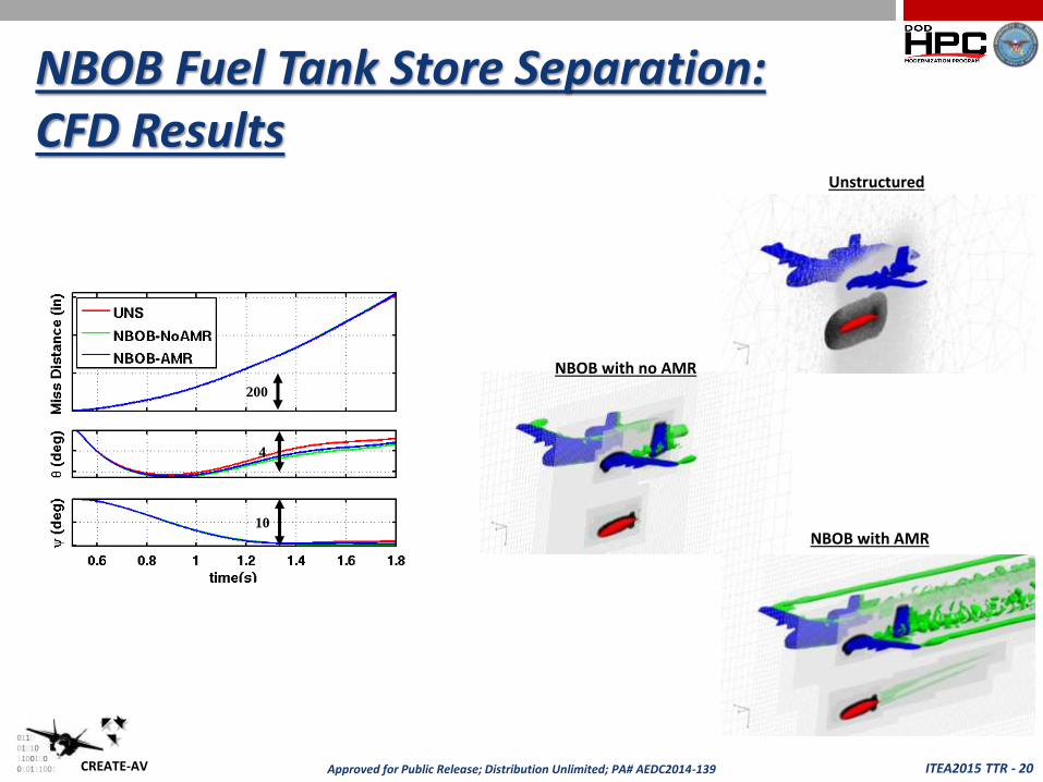
NBOB Fuel Tank Store Separation:CFD Simulation NBOB Benefits
– Easier mesh generation
– Better capture wake and off-body flow-field characteristics
Trimmed UNS mesh cells more than 15 inches from the surface– Orig Baseline A-10: 37 million; Trimmed Baseline A-10: 22 million
– Orig Tank: 7.5 million; Trimmed Tank: 5.5 million
Ran NBOB cases with/without AMR– Solution mesh refinement every 250 iterations for case with AMR
Cartesian solver– Initial Cartesian grid: 37 million cells (with/without AMR)
– Without AMR final Cartesian grid: 48 million cells (geometric refinement)
– With AMR final Cartesian grid: 183 million cells (geometric/solution refinement)
Solutions Times– All UNS: 10.5 sec/iter
– NBOB without AMR: 8.5 sec/iter
– NBOB with AMR 11.5 sec/iter
ITEA2015 TTR - 20CREATE-AV
0110010101100100010111001 Approved for Public Release; Distribution Unlimited; PA# AEDC2014-139
NBOB Fuel Tank Store Separation:CFD Results
200
4
10
NBOB with AMR
Unstructured
NBOB with no AMR
ITEA2015 TTR - 21CREATE-AV
0110010101100100010111001 Approved for Public Release; Distribution Unlimited; PA# AEDC2014-139
Conclusions
Assisted and added value to A-10 wind tunnel test program with Kestrel - Firebolt
Modeled A-10 wind tunnel test geometry for the baseline wing and one proposed wing modification
Included propulsion effects via the 0-D TF34-GE-100A engine model using FB Cap 1
Demonstrated A-10 full aircraft with full annulus TF34 rotating turbomachinery fan using FB Cap 2
Demonstrated store separation characteristics for baseline and proposed wing modification with full unstructured mesh system and NBOB mesh system
Provided feedback to developers to improve Kestrel-Firebolt
ITEA2015 TTR - 22CREATE-AV
0110010101100100010111001 Approved for Public Release; Distribution Unlimited; PA# AEDC2014-139
Acknowledgements:
The material presented in this paper is a product of the CREATETM-AV Element of the Computational Research and Engineering for Acquisition
Tools and Environments (CREATETM) Program sponsored by the US Department of Defense HPC Modernization Program (HPCMP) Office.
Computational resources were also provided by HPCMP.

ITEA2015 TTR - 23CREATE-AV
0110010101100100010111001 Approved for Public Release; Distribution Unlimited; PA# AEDC2014-139
Questions?
Related Documents