ENGINE AND EMISSION CONTROL – Engine Control System ENGINE CONTROL SYSTEM GENERAL INFORMATION A cable-type accelerator mechanism and a sus- pended-type pedal have been adopted. SERVICE SPECIFICATIONS Items Standard value Accelerator cable play mm 3–5 Engine idle speed rpm 700 ± 50 ON-VEHICLE SERVICE ACCELERATOR CABLE CHECK AND ADJUSTMENT 1. Turn A/C and lights OFF. Inspect and adjust at no load. 2. Warm engine until stabilised at idle. 3. Confirm idle speed is at prescribed rpm. 4. Stop engine (ignition switch OFF). 5. Confirm there are no sharp bends in accelerator cable. 6. Check inner cable for correct slack. 7. If there is too much slack or no slack, adjust play by the following procedures. (1) Loosen the adjusting bolt to release the cable. (2) After moving the plate to the position immediately before the throttle lever starts to move, move the plate back towards the throttle body by the standard value amount only to bring the accelerator cable play to the standard value. Standard value: 3–5 mm (3) Tighten the adjusting bolts to the specified torque. 8. Adjust accelerator cable play and confirm throttle lever stopper touches the fixed SAS. Main Index 17 Index Adjusting bolts Plate 5 Nm Fixed SAS

Welcome message from author
This document is posted to help you gain knowledge. Please leave a comment to let me know what you think about it! Share it to your friends and learn new things together.
Transcript

ENGINE AND EMISSION CONTROL – Engine Control System
ENGINE CONTROL SYSTEMGENERAL INFORMATIONA cable-type accelerator mechanism and a sus-pended-type pedal have been adopted.
SERVICE SPECIFICATIONS
Items Standard value
Accelerator cable play mm 3–5
Engine idle speed rpm 700 ± 50
ON-VEHICLE SERVICEACCELERATOR CABLE CHECK ANDADJUSTMENT1. Turn A/C and lights OFF.
Inspect and adjust at no load.2. Warm engine until stabilised at idle.3. Confirm idle speed is at prescribed rpm.4. Stop engine (ignition switch OFF).5. Confirm there are no sharp bends in accelerator cable.6. Check inner cable for correct slack.
7. If there is too much slack or no slack, adjust play bythe following procedures.(1) Loosen the adjusting bolt to release the cable.(2) After moving the plate to the position immediately
before the throttle lever starts to move, move theplate back towards the throttle body by the standardvalue amount only to bring the accelerator cable playto the standard value.
Standard value: 3–5 mm
(3) Tighten the adjusting bolts to the specified torque.
8. Adjust accelerator cable play and confirm throttle leverstopper touches the fixed SAS.
Adjusting bolts
Plate
5 Nm
Fixed SAS
Service Department

ENGINE AND EMISSION CONTROL – Engine Control System
ACCELERATOR CABLE AND PEDALREMOVAL AND INSTALLATION
Post-installation OperationAdjusting the Accelerator Cable (Refer to P.17-3.)
5 Nm
5 Nm
13 Nm
3
12
56
7
9
4
10
811
Removal steps of accelerator cable1. Accelerator cable connection2. Adjusting bolts
A 3. Accelerator cable4. Bolt
Removal steps of accelerator pedal5. Nut6. Accelerator pedal bracket7. Cotter pin8. Washer9. Accelerator pedal
10. Spring11. Accelerator pedal stopper

ENGINE AND EMISSION CONTROL – Engine Control System
INSTALLATION SERVICE POINTA ACCELERATOR CABLE INSTALLATIONAs shown in diagram, install so that the marked part is atthe top of the vehicle body.
Marked part
Accelerator cable

ENGINE AND EMISSION CONTROL – Cruise Control System
CRUISE CONTROL SYSTEMGENERAL INFORMATIONBy using the cruise control, the driver can driveat the speed he/she likes [in a range of approximate-
ly 40–200 km/h] without depressing the acceleratorpedal.
CONSTRUCTION DIAGRAM
Vacuum pump assembly
Stop light switch
Actuator
Inhibitor switch
Vehicle speed sensor
Throttle position sensor
Control unit
Control switch
Cruise control indicator

ENGINE AND EMISSION CONTROL – Cruise Control System
SERVICE SPECIFICATIONS
Items Standard value
Accelerator cable play mm 3–5
SPECIAL TOOLS
Tool Tool number and name Supersession Application
MB991502
MUT-
MB991502 Reading diagnosis troublecode
Auto-cruise control systeminspection
ROM Pack –
MB991529
Diagnosis trouble codecheck harness
Tool not necessary ifMUT-II is available
Checking the diagnosis troublecode.
Service Department

ENGINE AND EMISSION CONTROL – Cruise Control System
TROUBLESHOOTINGSTANDARD FLOW OF DIAGNOSIS TROUBLESHOOTINGRefer to GROUP 00 – How to use Troubleshooting/Inspection Service Points.
DIAGNOSIS FUNCTIONDIAGNOSIS CODES CHECKRead a diagnosis code by the MUT-II or voltmeter. (Referto GROUP 00 – How to use Troubleshooting/InspectionService Points.)
ERASING DIAGNOSIS CODESRefer to GROUP 00 – How to use Troubleshooting/InspectionService Points.METHOD OF ERASING DIAGNOSIS CODESThe diagnosis codes can be erased by disconnecting the(–) cable from the battery for 10 seconds or more and thenre-connecting it, or by the following procedure.1. Turn the ignition switch to ON.2. With the SET switch at the ON position, press the main
switch to ON, and within 1 second after this, turn theRESUME switch to ON.
3. With the SET switch once more at the ON position, holdthe stop light switch ON for a continuous period of 5seconds or more.
INPUT SWITCH CODE INSPECTION METHOD1. Connect the MUT-II to the diagnosis connector (16-pin)
underneath the instrument under cover.2. With the ignition switch in the ON position, press the
cruise control SET switch to the ON position.3. Within 1 second after pressing the cruise control main
switch to ON, turn the cruise control RESUME switchto ON.
4. Operate each switch listed in the input inspection tableand take a reading of the input switch codes with theMUT-II.
Main Switch
Cruise Control Switch

ENGINE AND EMISSION CONTROL – Cruise Control System
Input Inspection Table
Code No. Input operation Operation judgement
21 SET switch ON Cruise control-ECU judges that SET switch is ON
22 RESUME switch ON Cruise control-ECU judges that RESUME switch is ON
23 Stop light switch (ON when brake pedal is depressed)
Cruise control-ECU judges that stop light switch is ON
24 Cruise control-ECU judges that vehicle speed is 40 km/h or higher
25
Vehicle speed signalCruise control-ECU judges that vehicle speed is lower than40 km/h
26
Inhibitor switch (ON when select lever inN range) <A/T>Clutch pedal switch (ON when clutchpedal is depressed)<M/T>
Cruise control-ECU judges that the inhibitor switch or clutchpedal switch is ON
27 CANCEL switch ON Cruise control-ECU judges that CANCEL switch is ON
28 Throttle position sensor signal Cruise control-ECU judges that throttle position sensor vol-tage is 1.5 V or more
29 Idle position switch Cruise control-ECU judges that idle position switch is OFF
INSPECTION CHART FOR DIAGNOSIS CODES
Code No. Diagnosis items Reference page
11 Electric vacuum pump drive system P.17–10
12 Vehicle speed sensor system P.17–11
14 Electric vacuum pump power supply system P.17–11
15 Cruise control switch P.17–11
16 Cruise control-ECU P.17–12
17 Throttle position sensor system P.17–12

ENGINE AND EMISSION CONTROL – Cruise Control System
INSPECTION PROCEDURE FOR DIAGNOSIS CODES
Code No.11 Electric vacuum pump drive system Probable cause
[Comment]This diagnosis code is output if the release valve, control valve and motor drive signals fromthe electric vacuum pump are not input to the cruise control-ECU.
Malfunction of the electric vacuum pump Malfunction of the stop light switch Malfunction of the connector Malfunction of the harness Malfunction of the cruise control-ECU
NG
NG
OK
OK
OK
OK
NG
Replace
NGReplace
OKNG
Repair
OK
NG NG Repair
OK
NG Repair NG
Cruise control component [electricvacuum pump] inspection(Refer to P.17-28.)
Measure at electric vacuum pump con-nector A-01. Disconnect the connector and
measure at the harness side. Voltage between terminal (1) and
groundOK: Battery positive voltage
Measure at cruise control-ECU connec-tor B-101. Disconnect the connector and
measure at the harness side. Voltage between terminal (7) and
ground (for driving release valve) Voltage between terminal (8) and
ground (for driving control valve) Voltage between terminal (16) and
ground (for driving motor)OK: Battery positive voltage
Check the following connector. B-101.
Check trouble symptom
Replace the cruise control-ECU.
Check trouble symptom
Cruise control component [stop lightswitch] inspection(Refer to P.17-27.)
Check the following connectors.B-18 B-74, B-76.
Check trouble symptom
Check the following connector.A-01.
Check the harness between the electricvacuum pump and cruise control-ECU,and repair if necessary.
Service Department

ENGINE AND EMISSION CONTROL – Cruise Control System
Code No.12 Vehicle speed signal system Probable cause
[Comment]This diagnosis code is output if the vehicle speed signals from the vehicle speed sensor arenot input to the cruise control-ECU when the vehicle speed is 40 km/h or more.
Malfunction of the vehicle speed sensor Malfunction of the connector Malfunction of the harness Malfunction of the cruise control-ECU
Yes
NG
NO
OK NGRepair
OK
NG
Is the speedometer operating normally?
Disconnect the vehicle speed sensorA-88.
Measure at cruise control-ECU connec-tor B-101. Disconnect the connector and
measure at the harness side. Voltage between terminal (10) and
ground.OK: 4.5 V or more.
Check the harness between the vehiclespeed sensor and cruise control-ECU,and repair if necessary.
Vehicle speed sensor circuit inspection(Refer to GROUP 54 – CombinationMeter.)
Check the following connector.B-101.
Check trouble symptom
Replace the cruise control-ECU.
Code No.14 Electric vacuum pump power supply system Probable cause
This diagnosis code is output if the electric vacuum pump release valve, control valve andmotor driving signals are not input into the cruise control ECU.
Stop lamp switch fault Connector fault Harness fault Cruise control ECU fault
NG
OK
OK
OK
NG
OK
NGReplace
Measure at electric vacuum pump con-nector A-01. Measure at the harness side with
the connector disconnected. Voltage between terminal (1) and
groundOK: Battery voltage
Check stop lamp switch (See P.17-27).
Check trouble symptom
Check connectors B–74 and B–18.
NG
NGRectify
Check connectors A–01, A–28 andB–101.
Check trouble symptom
Replace cruise control ECU
Check and rectify the harness betweenthe electric vacuum pump and thecruise control ECU
NGRectify
Code No.15 Cruise control switch Probable cause
[Comment]This diagnosis code is output if the cruise control RESUME switch, SET switch or CANCELswitch remains ON.
Malfunction of the cruise control switch
Replace the cruise control switch.

ENGINE AND EMISSION CONTROL – Cruise Control System
Code No.16 Cruise control-ECU Probable cause
[Comment]This diagnosis code is output if there is an abnormality in the CANCEL hold circuit or themicroprocessor monitor circuit in the cruise control-ECU.
Malfunction of the cruise control-ECU
Replace the cruise control-ECU.
Code No.17 Throttle position sensor system Probable cause
[Comment]This diagnosis code is output if a voltage of 1.5 V or more when the idle position switch isON or 0.2 V or less when the idle position switch is OFF is output for a continuous periodof 4 seconds or more.
Malfunction of the throttle position sensor Malfunction of the connector Malfunction of the harness Malfunction of the cruise control-ECU
NO
Yes
NG Repair
NGRepair
MUT-II Self-Diagnosis codeIs diagnosis code No. 14 output fromthe engine control module?
Check the following connector.B-101.
Check trouble symptom
Inspect the harness between thethrottle position sensor and cruisecontrol-ECU
Replace the cruise control-ECU.
Throttle position sensor inspection(Refer to GROUP 13A – On-vehicleInspection of MPI Components.)
OK
NG
OK

ENGINE AND EMISSION CONTROL – Cruise Control System
INSPECTION CHART FOR TROUBLE SYMPTOMS
Trouble symptom Inspectionprocedure No. Reference page
Communication with Communication with all systems is not possible. 1 See belowMUT-II is not possible.
Communication with cruise control-ECU only is notpossible. 2 P.17-14
Input switch inspection using the MUT-II is not possible. (However, diagnosisinspection is possible.) 3 P.17-15
Cruise control is not Even if brake pedal is depressed 4 P.17-16cancelled.
Even if the clutch pedal is depressed <M/T> 5 P.17-17
Even if the select lever is set to N range <A/T> 6 P.17-18
Even if CANCEL switch is set to ON 7 P.17-18
The diagnosis result displayed on the MUT-II is normal even though cruisecontrol cannot be set. 8 P.17-19
Cruise control cannot be set. 9 P.17-20
Hunting (repeated acceleration and deceleration) occurs at the set vehiclespeed. 10 P.17-21
Even though cruise control main switch is ON, switch indicator does not illumi-nate. (However, cruise control is normal.) 11 P.17-21
Cruise control main switch illumination light does not illuminate. 12 P.17-22
Cruise control indicator light inside combination meter does not illuminate.(However, cruise control is normal.) 13 P.17-22
INSPECTION PROCEDURE FOR TROUBLE SYMPTOMSINSPECTION PROCEDURE 1
Communication with MUT-II is not possible. (Communication with all systems is not possible.) Probable cause
[Comment]The reason is probably a defect in the power supply system (including ground) for the diagnosis line.
Malfunction of the connector Malfunction of the harness
Refer to GROUP 13A – Troubleshooting

ENGINE AND EMISSION CONTROL – Cruise Control System
INSPECTION PROCEDURE 2
Communication with MUT-II is not possible. (Communicationwith cruise control-ECU only is not possible.) Probable cause
[Comment]The cause is probably a malfunction of auto-cruise control main switch circuit or a malfunctionof cruise control-ECU ground circuit.
Malfunction of the cruise control main switch Malfunction of the connector Malfunction of the harness Malfunction of the cruise control-ECU
*1
OK
*2
NGReplace
OK
OKNG
NG
OK
NG
NGRepair
NG
OK
OK
NGNG
Repair Repair
NG
Cruise control main switch inspection(Refer to P.17-32.)
Measure at cruise control main switchconnector B-23. Disconnect the connector and
measure at the harness side. Voltage between the terminal (2)
and groundOK: Battery positive voltage
Check the following connectors. B-23, B-76, B-77, B-101.
Check trouble symptom
Check the harness between the cruisecontrol main switch and power supply,and repair if necessary.
Check the following connector.B-76
Measure at cruise control-ECU connec-tor B-101. Disconnect the connector and
measure at the harness side. Continuity between terminal (6) and
ground, terminal (8) and ground andbetween terminal (14) and ground.OK: Continuity
Check trouble symptom
Check the harnesses between the cru-ise control main switch and ground orbetween the cruise control main switchand cruise control-ECU, and repair ifnecessary.
Check the harness between the cruisecontrol-ECU and ground, and repair ifnecessary.
Check the following connector.B-101
Check trouble symptom
Replace the cruise control-ECU.
NOTE*1 indicates malfunction of the cruise control main switch circuit.*2 indicates malfunction of the cruise control-ECU ground circuit.
Service Department

ENGINE AND EMISSION CONTROL – Cruise Control System
INSPECTION PROCEDURE 3
Input switch inspection using the MUT-II is not possible.(However, diagnosis inspection is possible.) Probable cause
[Comment]The cause is probably a malfunction of cruise control switch circuit system.
Malfunction of the cruise control switch Malfunction of the clock spring Malfunction of the connector Malfunction of the harness
OK
OK
OK
OK
NG
NGReplace
NGReplace
NG NGRepair
OK
NG Repair
NG
Check the harness between the clockspring and cruise control-ECU, and re-pair if necessary.
Cruise control switch inspection (Referto P.17-32.)
Clock spring inspection (Refer toGROUP 52B – Air Bag Modulesand Clock Spring.)
Measure at clock spring connectorB-30. Ground Voltage between terminal (2) and
groundOK: Battery positive voltage
Check the following connectors.B-30 and B-41
Check trouble symptom
Check the following connectors.B-30, B-76 and B-77.
Check trouble symptom
Check the harness between the clockspring and power supply, and repairif necessary.
Service Department

ENGINE AND EMISSION CONTROL – Cruise Control System
INSPECTION PROCEDURE 4
Even if brake pedal is depressed, cruise control is not can-celled. Probable cause
[Comment]The cause is probably a malfunction of stop light switch or a malfunction of stop light circuit.
Malfunction of the stop light switch Malfunction of the connector Malfunction of the harness Malfunction of the cruise control-ECU
NO
OK
OK
OK
NG
Yes
NGReplace
NG NG Repair
OK
NGRepair
NG
Does stop light illuminate?
Cruise control component [stop lightswitch] inspection(Refer to P.17-27.)
Measure at stop light switch connectorB-18. Disconnect the connector and
measure at the harness side. Voltage between terminal (2) and
groundOK: Battery positive voltage
Check the following connectors.B-18, B-41 and B-101.
Check trouble symptom
Check the harness between the stoplight switch and junction block (1), andrepair if necessary.
Replace the cruise control-ECU.
Check the following connectors.B-76 and B-85.
Check trouble symptom
Check the harness between the stoplight switch and power supply, and re-pair if necessary.
Service Department

ENGINE AND EMISSION CONTROL – Cruise Control System
INSPECTION PROCEDURE 5
Even if clutch pedal is depressed, cruise control is not can-celled. <M/T> Probable cause
[Comment]The cause is probably a malfunction of clutch pedal position switch or clutch circuit.
Malfunction of the clutch pedal position switch Malfunction of the connector Malfunction of the harness Malfunction of the cruise control-ECU
NGOK
OK
OK
NGReplace
NG
NG
Repair
Repair
Clutch pedal position switch inspection(Refer to P.17-28.)
Measure at clutch pedal position switchconnector B-96. Disconnect the connector and
measure at the harness side. Voltage between terminal (2) and
groundOK: Battery positive voltage
Check the following connectors.B-41, B-96.
Check trouble symptom
Check the following connectors.B-41, B-96, B-101.
Inspect the harness between the clutchpedal position switch and ground.
Check the harness between the clutchpedal position switch and cruise control-ECU and repair if necessary.
NGReplace the cruise control-ECU.
Check trouble symptom
NG
Repair
OK
NG

ENGINE AND EMISSION CONTROL – Cruise Control System
INSPECTION PROCEDURE 6
Even if select lever is set to N range, cruise control is not can-celled. <A/T> Probable cause
[Comment]The cause is probably an open-circuit in the output signal circuit in N range.
Malfunction of the connector Malfunction of the harness Malfunction of the cruise control-ECU
NG
Repair
OK
NGNG
Repair
OK
Check the following connectors.A-89 and B-101.
Check trouble symptom
Inspect the harness between the inhibi-tor switch and cruise control-ECU.
Replace the cruise control-ECU.
INSPECTION PROCEDURE 7
Even if cruise control CANCEL switch is set to ON, cruise con-trol is not cancelled. Probable cause
[Comment]The cause is probably an open-circuit in the circuit inside the CANCEL switch.
Malfunction of the cruise control-ECU
Replace the cruise control switch.
Service Department

ENGINE AND EMISSION CONTROL – Cruise Control System
INSPECTION PROCEDURE 8
The diagnostic result displayed on the MUT-II is normal eventhough cruise control cannot be set. Probable cause
[Comment]Because of an open-circuit in the battery backup circuit system, the fail-safe function preventsdiagnosis codes from being memorised and displayed even though cruise control is cancelled.
Malfunction of the connector Malfunction of the harness Malfunction of the cruise control-ECU
OK
OK
NG
NG NGRepair
OK
NG
Measure at cruise control-ECU connec-tor B-101. Disconnect the connector and
measure at the harness side. Voltage between terminal (6) and
groundOK: Battery positive voltage
Check the following connector.B-101
Check trouble symptom
Replace the cruise control-ECU.
Check the following connectors.B-76, B-80, B-41 and B-101.
Check trouble symptom
Check the harness between the cruisecontrol-ECU and power supply, and re-pair if necessary.
Service Department

ENGINE AND EMISSION CONTROL – Cruise Control System
INSPECTION PROCEDURE 9
Cruise control cannot be set. Probable cause
[Comment]The cause is probably that the fail-safe function is cancelling cruise control. In this case,the MUT-II can be used to check the trouble symptoms in each system by inspecting thediagnosis codes. The MUT-II can also be used to check if the circuits of each input switchare normal or not by inspecting the input switch codes.
Malfunction of the cruise control main switch Malfunction of the cruise control switch Malfunction of the clock spring Malfunction of the harnesses or connectors Malfunction of the cruise control-ECU
Yes
No
No
Yes
No
No
Yes
Yes
No
Yes
Can the cruise control communicate with the MUT-II?
Is the diagnosis system diagnosis displayed on the MUT-IInormal?
Are any of MUT-II diagnosis code Nos. 11, 12, 15, 16 or17 output?
Is input switch inspection possible with the MUT-II?
Are either of MUT-II diagnosis code Nos. 23 or 26 output?
Replace the cruise control-ECU.
Inspection for each trouble symptom. (Refer to inspection procedure No. 2 on P.17-14.)
Inspection for each trouble symptom. (Refer to inspection procedure No. 8 on P.17-19.)
Inspection for each diagnosis code.(Code No.11: Refer to P.17-10.)(Code No.12: Refer to P.17-11.)(Code No.15: Refer to P.17-11.)(Code No.16: Refer to P.17-11.)(Code No.17: Refer to P.17-12.)
Inspection for each trouble symptom. (Refer to inspection procedure No. 3 on P.17-15.)
Stop light switch input circuit system [code No. 23] in-spection (Refer to inspection procedure No. 4 P.17-16.)
Inhibitor switch input circuit system [code No.26] inspec-tion (Refer to inspection procedure No.5 on P.17-17.)
Service Department

ENGINE AND EMISSION CONTROL – Cruise Control System
INSPECTION PROCEDURE 10
Hunting (repeated acceleration and deceleration) occurs at theset vehicle speed. Probable cause
[Comment]The cause is probably a malfunction of vehicle speed sensor or incorrect vacuum in the electricvacuum pump or actuator.
Malfunction of the vehicle speed sensor Malfunction of the electric vacuum pump Malfunction of the actuator Malfunction of the cruise control-ECU
OK
OK
Actuator inspection (Refer to P.17-29.)
OK
Electric vacuum pump inspection (Refer to P.17-28.)
Vehicle speed sensor inspection (Refer to GROUP 54 – Combination Meter.)
Replace the cruise control-ECU.
NG
NG
NG
Replace
Replace
Replace
INSPECTION PROCEDURE 11
Even though cruise control main switch is ON, switch indica-tor does not illuminate. (However, cruise control is normal.) Probable cause
[Comment]Blown bulb in cruise control main switch
Malfunction of the cruise control main switch
Replace the cruise control main switch.
Service Department
Service Department

ENGINE AND EMISSION CONTROL – Cruise Control System
INSPECTION PROCEDURE 12
Cruise control main switch illumination light does not illumi-nate. Probable cause
[Comment]The cause is probably a malfunction of cruise control main switch or a malfunction of harnessor connector.
Malfunction of the cruise control main switch Malfunction of the connector Malfunction of the harness
OK
OK
OK
NG
NGReplace
NG NGRepair
OK
NGRepair
NG
Cruise control main switch inspection(Refer to P.17-32.)
Measure at cruise control main switchconnector B-23. Disconnect the connector and
measure at the harness side. Voltage between terminal (2) and
groundOK: Battery positive voltage
Check the following connectors.B-23.
Check trouble symptom
Check the harness between the cruisecontrol main switch and junction block(2), and repair if necessary.
Check the following connectors.B-30 and B-77.
Check trouble symptom
Check the harness between the cruisecontrol main switch and power supply,and repair if necessary.
INSPECTION PROCEDURE 13
Cruise control indicator inside combination meter does not il-luminate. (However, cruise control is normal.) Probable cause
[Comment]The cause is probably a malfunction of bulb or a malfunction of connector or harness.
Malfunction of the bulb Malfunction of the harness Malfunction of the connector Malfunction of the cruise control-ECU
OK
Yes
NGReplace
No NGRepair
OK
NG
Check bulb in combination meter.
Indicator illuminates when terminal No.15 of auto-cruise control-ECU harness-side connector B-101 is grounded.
Replace the cruise control-ECU.
Check the following connectors.B-77, B-80, B-101, C-03, C-04, C-05.
Check trouble symptom
Check the harness between the com-bination meter and Assist-ECU and be-tween Assist-ECU and cruise ECU, andrepair if necessary.
Service Department
Service Department

ENGINE AND EMISSION CONTROL – Cruise Control System
INSPECTION PROCEDURE 14
Stop light switch input circuit system inspection (Code No. 23)
OKNG
NGRepairCheck the following connectors.
B–18, B-41, B-74 B-76, B-85 and B-101.
Check trouble symptom Check the harness between junction block (2) and cruisecontrol-ECU, and repair if necessary.
INSPECTION PROCEDURE 15
Inhibitor switch input circuit system inspection (Code No. 26)
Check the harness between cruise control-ECU and powersupply.

ENGINE AND EMISSION CONTROL – Cruise Control System
CHECK AT ECU TERMINALS
TerminalNo. Check item Check conditions Normal
condition
Throttle positionsensor input/ac-
When the accelerator pedal is depressed fully4.0–5.5V
1 celerator pedalposition sensorinput
When the accelerator pedal is returned0.5–0.7V
Closed throttle When the accelerator pedal is depressed (Idle switch ON) 4.5–5.5V2 position switch
input When the accelerator switch is not depressed (Idle switchOFF)
0V
No OD-OFF request Battery voltage3 A/T control output
OD-OFF request 0V
When the brake pedal is depressed (Stop lamp switch ON) Battery voltage
4 Stop lamp switchinput When the brake pedal is not depressed (Stop lamp switch
OFF) 0V
Ignition switch ON
5 Pump power Main switch ON Battery voltagesupply
Stop lamp switch OFF
ECU power Ignition switch ON6 ECU power
supply Main switch ONBattery voltage
7 Electric vacuum When decelerating with the set Release valve closed 0V
8pump releasevalve,control
switch during travel at a con-stant speed Control valve open Battery voltage
7valve input
When constant speed travel is Release valve open Battery voltage
8cancelled with the cancelswitch Control valve closed Battery voltage
When not operated (All switches OFF) 0V
Cruise control When Flicked down (Set switch ON) 3V9 Cruise control
switch input When flicked up (Resume switch ON) 6V
When flicked toward the driver (Cancel switch ON) Battery voltage
Vehicle speed The sensor repeatedly turns Sensor ON 0V10 Vehicle speed
sensor input ON/OFF when the vehiclemoves forwards or backwards Sensor OFF 4.5V
Diagnosis control Ignition switch ON11 Diagnosis controlinput
Ignition switch ON 4.0V or greater
12 ACC powersupply When the ignition switch is on ACC Battery voltage
Service Department

ENGINE AND EMISSION CONTROL – Cruise Control System
TerminalNo.
Normal conditionCheck conditionsCheck item
Inhibitor switchWhen the shift lever is other than in the N position (Inhibitorswitch OFF) Battery voltage
13input <A/T>
When the shift lever is in the N position (Inhibitor switch ON) 0V13
Clutch pedal When the clutch pedal is released (switch OFF) Battery voltageswitch input<M/T> When the clutch pedal is pressed (switch ON) 0V
14 Ground – –
Indicator lamp When travelling at constant-speed (Indicator lamp illuminated) 0V
15 input (In combinationmeter)
When constant-speed travel cancelled (Indicator lampextinguished) Battery voltage
During constant-speed travel with Set switch (Motor stopped/running
Battery voltage/0V
Electric vacuum
Accelerating with Resume switch during constant-speed travel(Motor stopped/running)
Battery voltage/0V
16 Electric vacuumpump motor input Decelerating with Set switch during constant-speed travel
(Motor stopped) Battery voltage
Constant-speed travel cancelled with Cancel switch(Motor stopped) Battery voltage

ENGINE AND EMISSION CONTROL – Cruise Control System
ON-VEHICLE SERVICECRUISE CONTROL SYSTEM OPERATION CHECK
CRUISE CONTROL MAIN SWITCH INDICATOR LIGHT1. Turn the ignition key to ON2. Check to be sure that the indicator within the switch illumi-
nates when the main switch is switched ON.
CRUISE CONTROL SETTING1. Switch ON the main switch.2. Drive at the desired speed within the range of
approximately 40–200 km/h.3. Switch ON the SET switch.4. Check to be sure that when the switch is released the
speed is the desired constant speed.NOTEIf the vehicles speed decreases to approximately 15 km/hbelow the set speed because of climbing a hill for example,the cruise control will be cancelled.
SPEED-INCREASE SETTING1. Set to the desired speed.2. Switch ON the RESUME switch.3. Check to be sure that acceleration continues while the
switch is hold, and that when it is released the constantspeed at the time when it was released becomes thedriving speed.
SPEED REDUCTION SETTING1. Set to the desired speed.2. Switch ON the SET switch.3. Check to be sure that deceleration continues while the
switch is pressed, and that when it is released the constantspeed at the time when it was released becomes thedriving speed.NOTEWhen the vehicle speed reaches the low limit [approxi-mately 40 km/h during deceleration, the cruise controlwill be cancelled.
Cruise control main switch
SET switch : ON
RESUME switch: ON
SET switch: ON

ENGINE AND EMISSION CONTROL – Cruise Control System
CANCEL switch: ON
RETURN TO THE SET SPEED BEFORE CANCELLATIONAND CRUISE CONTROL CANCELLATION1. Set the cruise speed control.2. When any of the following operations are performed while
at constant speed during cruise control, check if normaldriving is resumed and deceleration occurs.(1) Switch ON the CANCEL switch.(2) The brake pedal is depressed.(3) The selector lever is moved to the “N” range <A/T>.(4) The clutch pedal is depressed <M/T>.
3. At a vehicle speed of 40 km/h or higher, check if whenthe RESUME switch is switched ON, vehicle speed returnsto the speed before cruise control driving was cancelled,and constant speed driving occurs.
4. When the main switch is turned to OFF while drivingat constant speed, check if normal driving is resumedand deceleration occurs.
CRUISE CONTROL COMPONENT CHECK
STOP LIGHT SWITCH
Measurementconditions
For stop lightcircuitTerminal No.
For cruise con-trol circuitTerminal No.
2 3 1 4
When brake pedaldepressed.
When brake pedal notdepressed.
THROTTLE POSITION SENSORRefer to GROUP 13A – On-vehicle Inspection of MPI Compo-nents.
RESUME switch: ON

ENGINE AND EMISSION CONTROL – Cruise Control System
INHIBITOR SWITCH (“N” POSITION)
Measurement conditions Terminal No.
4 8 9 10
Selector lever is at ”N” position
Selector lever is not at ”N” position
CLUTCH PEDAL SWITCH
Measurement conditions Terminal No.
1 2
When clutch pedal is depressed
When clutch pedal is not depressed
CRUISE VACUUM PUMP1. Disconnect the vacuum hose from the electric vacuum
pump and connect a vacuum gauge to the vacuum pump.2. Disconnect the electric vacuum pump connector.
3. Connect terminal (1) to the battery (+) terminal, and con-nect terminals (2) and (3) to the battery (–) terminal.
4. Check to be sure that the vacuum gauge shows a readingof 53 kPa (398 mm Hg)or more when terminal (4) is con-nected to the battery (–) terminal.
Vacuumgauge
<Release valve closed, control valveclosed>
Battery

ENGINE AND EMISSION CONTROL – Cruise Control System
5. In this condition, check to be sure that the vacuum gaugeshows a 20 kPa (150 mm Hg) or less when terminals (2)and (3) are disconnected from the battery.
ACTUATOR1. Disconnect the vacuum hose from the vacuum actuator
and connect a hand vacuum pump to the vacuum actuator.2. Confirm that the throttle lever operates and the vacuum
is also maintained when a vacuum is present.
<Release valve open>
Battery
<Control valve open>
Battery
Cruise control

ENGINE AND EMISSION CONTROL – Cruise Control System
CRUISE CONTROLREMOVAL AND INSTALLATION
1
2
3
4
Vacuum pump removal steps1. Vacuum hose2. Electric vacuum pump and bracket
assembly
3. Electric vacuum pump4. Bracket

ENGINE AND EMISSION CONTROL – Cruise Control System
CAUTION: SRSBefore removal of air bag module and clockspring, refer to the followings:GROUP 52B – SRS Service Precautions.GROUP 52B – Air Bag Modules and ClockSpring.
11
7
109
6
8
Control switch removal steps Airbag module (See group 52B)6. Control switch
Control unit removal steps Floor console box assembly
(See group 52A) Centre air outlet assembly
(See group 52-Instrument Panel) Ash tray
(See group 52A-Instrument Panel)
Air conditioner control unit and radio/tape player
7. Cruise control ECU
Sensor removal steps8. Throttle position sensor9. Inhibitor switch
10. Stop lamp switch11. Clutch pedal switch

ENGINE AND EMISSION CONTROL – Cruise Control System
INSPECTIONCRUISE CONTROL SWITCH CHECKMeasure the resistance between the terminals when eachof the SET, RESUME and CANCEL switches is pressed.If the values measured at this time correspond to those inthe table below, then there is no problem.
Switch position Resistance between terminals
Switch OFF No continuity
CANCEL switch ON Approx. 1.1 kΩ
RESUME switch ON Approx. 331 Ω
SET switch ON Approx. 3.1 kΩ
MAIN switch held in 0 Ω
MAINRESUME
SETCANCEL
1
2
Service Department
Service Department

ENGINE AND EMISSION CONTROL – Emission Control System
EMISSION CONTROL SYSTEMGENERAL INFORMATIONThe emission control system consists of the following subsystems: Positive crankcase ventilation system Evaporative emission control system Exhaust emission control system
Items Name Specification
Crankcase emissioncontrol system
Positive crankcase ventilation (PCV) valve Variable flow type(Purpose: HC reduction)
Evaporative emissioncontrol system
CanisterPurge control valve
EquippedManifold vacuum purge(Purpose: HC reduction)
Exhaust emissioncontrol system
Air-fuel ratio control device–MPI system(vehicles with catalytic converter)
Oxygen sensor feedback type(Purpose: CO, HC, NOx reduction)
Exhaust gas recirculation system EGR valve EGR control solenoid valve
EquippedSingle typeDuty cycle type solenoid valve(Purpose: NOx reduction)
Catalytic converter Monolith type(Purpose: CO, HC, NOx reduction)
EMISSION CONTROL DEVICE REFERENCE TABLE
Related parts
Crankcaseemissioncontrolsystem
Evaporativeemissioncontrolsystem
Air/fuelratiocontrolsystem
Catalyticconverter
Exhaustgasrecircula-tionsystem
Referencepage
PCV valve X 17-38
MPI system component X X Group 13A
EGR valve X 17-46
EGR control solenoidvalve X 17-47
Catalytic converter X 17-48
SERVICE SPECIFICATIONS
Items Specification
EGR control solenoid valve coil resistance [at 20C] Ω 36–44
Service Department
Service Department
Service Department
Service Department
ENGINE AND EMISSION CONTROL – Emission Control System
SPECIAL TOOL
Tool Tool number and name Supersession Application
MD998770
Oxygen sensorwrench
– Removal/Installation of heatedoxygen sensor
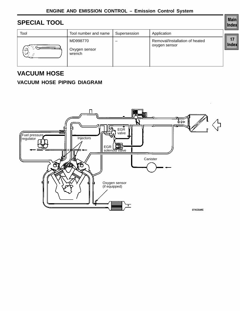
VACUUM HOSEVACUUM HOSE PIPING DIAGRAM
Canister
EGR solenoid valve
Oxygen sensor(if equipped)
EGRvalveFuel pressure
regulator Injectors
Service Department

ENGINE AND EMISSION CONTROL – Emission Control System
VACUUM CIRCUIT DIAGRAM
EGR solenoid(ON: closed)
Intake air plenum
Throttle body
From aircleaner
Fuel pressureregulator
Canister
EGRvalve
To combustionchamber
M
E P A
L
R
B
G
Y
GG

ENGINE AND EMISSION CONTROL – Emission Control System
VACUUM HOSE INSTALLATION1. When connecting the vacuum hoses, they should be securely
inserted onto the nipples.2. Connect the hoses correctly, using the VACUUM HOSE PIPING
DIAGRAM as a guide.
VACUUM HOSE INSPECTION1. Using the VACUUM HOSE PIPING DIAGRAM as a guide, check
to be sure that the vacuum hoses are correctly connected.2. Check the connection condition of the vacuum hoses, (removed,
loose, etc.) and check to be sure that there are no bends ordamage.

ENGINE AND EMISSION CONTROL – Emission Control System
PCV valve
CRANKCASE EMISSION CONTROL SYSTEMGENERAL INFORMATIONThe crankcase emission control system is a systemfor preventing the escape of blow-by gases frominside the crankcase into the atmosphere.Fresh air is sent from the air cleaner into the crank-case through the breather hose to be mixed withthe blow-by gases inside the crankcase.The blow-by gas inside the crankcase is drawninto the intake manifold through the positive crank-case ventilation valve.
The positive crankcase ventilation valve is designedto lift the plunger according to the intake manifoldvacuum so as to regulate the flow of blow-by gasproperly.In other words, the blow-by gas flow is regulatedduring low load engine operation to maintain enginestability, while the flow is increased during highload operation to improve the ventilation perform-ance.
SYSTEM DIAGRAM
Breather hose
Positive crankcaseventilation valve
Ventilation hose
Catalytic converter <if equipped>
COMPONENT LOCATIONPositive crankcase ventilation valve

ENGINE AND EMISSION CONTROL – Emission Control System
POSITIVE CRANKCASE VENTILATION SYSTEMCHECK
1. Remove the ventilation hose from the positive crankcaseventilation valve.
2. Remove the positive crankcase ventilation valve fromthe rocker cover.
3. Reinstall the positive crankcase ventilation valve at theventilation hose.
4. Start the engine and run at idle.
5. Place a finger at the opening of the positive crankcaseventilation valve and confirm that vacuum of the intakemanifold is felt.
NOTEAt this moment, the plunger in the positive crankcaseventilation valve moves forward and backward.
6. If vacuum is not felt, clean the positive crankcase ventila-tion valve or replace it.
7. Install the positive crankcase ventilation valve.
POSITIVE CRANKCASE VENTILATION (PCV)VALVE CHECK1. Insert a thin rod into the positive crankcase ventilation
valve from the side shown in the illustration (rocker coverinstallation side), and move the rod back and forth toconfirm that the plunger moves.
2. If the plunger does not move, there is a clogging in thepositive crankcase ventilation valve. In this case, cleanor replace the valve.
Positive crankcaseventilation valve
Positive crankcaseventilation

ENGINE AND EMISSION CONTROL – Emission Control System
EVAPORATIVE EMISSION CONTROL SYSTEMGENERAL INFORMATIONThe evaporative emission control system preventsfuel vapours generated in the fuel tank from escap-ing into the atmosphere.Fuel vapours from the fuel tank flow through thefuel tank pressure control valve and vapour pipe/hose to be stored temporarily in the EVAP canister.When the vehicle is in operation, fuel vapours storedin the EVAP canister flow through the EVAP purgesolenoid and purge port and go into the intakemanifold plenum to be sent to the combustionchamber.
When the engine coolant temperature is low orwhen the intake air quantity is small (when theengine is at idle, for example), the engine controlmodule brings the EVAP purge solenoid into theOFF state to shut off the fuel vapour flow to theintake manifold plenum. This does not only insurethe driveability when the engine is cold or runningunder low load but also stabilise the emission level.
SYSTEM DIAGRAM
CanisterFrom fuel tank
OFF
ON
Controlrelay
Enginecontrolmodule
Volume air flow sensor
Intake air temperaturesensor
Barometric pressuresensor
Engine coolant temperaturesensor
Throttle body
Purge controlsolenoid valve
COMPONENT LOCATIONEvaporative emission purge solenoid

ENGINE AND EMISSION CONTROL – Emission Control System
PURGE CONTROL SYSTEM CHECK1. Disconnect the vacuum hose (red stripes) from the throttle
body and connect it to a hand vacuum pump.2. Plug the nipple from which the vacuum hose was removed.3. When the engine is cold and hot, apply a vacuum while
the engine is idling, and check the condition of the engineand the vacuum.
When engine is cold[Engine coolant temperature: 40C or less]
Vacuum Engine status Normal condition
400 mmHg 3,000 rpm Vacuum is main-tained
When engine is hot[Engine coolant temperature: 80C or higher]
Vacuum Engine status Normal condition
400 mmHg Idling Vacuum is main-tained
3,000 rpm Vacuum will leakfor approximately3 minutes afterthe engine isstarted.After 3 minuteshave elapsed, thevacuum will bemaintained mo-mentarily, afterwhich it will againleak.*
NOTE* The vacuum will leak continuously if the atmospheric
pressure is approximately 580 mmHg or less, or thetemperature of the intake air is approximately 50Cor higher.
Vacuum hose(red stripe)
Plug

ENGINE AND EMISSION CONTROL – Emission Control System
PURGE PORT VACUUM CHECK1. Disconnect the vacuum hose (red stripe) from the throttle
body purge vacuum nipple and connect a hand vacuumpump to the nipple.
2. Start the engine and check to see that, after raising theengine speed by racing the engine, purge vacuum raisesproportionately with the rise in engine speed.
NOTEIf there is a problem with the change in vacuum, it ispossible that the throttle body purge port may be cloggedand require cleaning.
EVAPORATIVE EMISSION PURGE SOLENOIDCHECK1. Remove the engine cover. Refer to GROUP 11B.2. Disconnect the vacuum hose (black stripe, red stripe)
from the solenoid valve.
NOTEBefore disconnecting the vacuum hose, always makea mark so that it can be reconnected at original position.
3. Disconnect the harness connector.
4. Connect a hand vacuum pump to nipple (A) of the solenoidvalve (refer to the illustration at left).
5. Check air tightness by applying a vacuum with voltageapplied directly from the battery to the purge control so-lenoid valve and without applying voltage.
Battery voltage Normal condition
Applied Vacuum leaks
Not applied Vacuum maintained
6. Measure the resistance between the terminals of the so-lenoid valve.
Standard value: 36–44 Ω [at 20C]
Vacuum hose(red stripe)
Vacuum
Engine speed (rpm)
A
Battery
B

ENGINE AND EMISSION CONTROL – Emission Control System
VOLUME AIR FLOW SENSOR, ENGINE COOLANTTEMPERATURE SENSOR AND INTAKE AIRTEMPERATURE SENSOR CHECKTo inspect these parts, refer to GROUP 13A – On-vehicleInspection of MPI Components.
AIR CONDITIONING SWITCH CHECKTo inspect the air conditioning switch, refer to GROUP 55– Air Conditioning Switch.

ENGINE AND EMISSION CONTROL – Emission Control System
CANISTER AND TWO WAY VALVEREMOVAL AND INSTALLATION
1
2
3
45
Removal steps1. Vapour hose2. Purge hose connection3. Canister4. Breather valve5. Canister bracket
INSPECTIONTWO-WAY VALVERefer to GROUP 13F – Fuel Supply

ENGINE AND EMISSION CONTROL – Emission Control System
EXHAUST GAS RECIRCULATION (EGR) SYSTEMGENERAL INFORMATIONThe exhaust gas recirculation (EGR) system lowersthe nitrogen oxide (NOx) emission level. When theair/fuel mixture combustion temperature is high,a large quantity of nitrogen oxides (NOx) is gener-ated in the combustion chamber. Therefore, thissystem recirculates part of emission gas from theexhaust port of the cylinder head to the combustionchamber through the intake manifold to decreasethe air/fuel mixture combustion temperature, result-ing in reduction of NOx.The EGR flow rate is controlled by the EGR valveso as not to decrease the driveability.
OPERATIONWhen the engine coolant temperature is low, whenthe engine is at idle or when a wide open throttleoperation is performed, the EGR valve is keptclosed, achieving no EGR. In normal vehicleoperation performed after warming up of the engine,the EGR valve is opened to carry out EGR.
The engine control module monitors EGR systemvia the manifold differential pressure sensor andturns on the check engine/malfunction indicatorlight to notify the driver if a failure occurs in theEGR system.
SYSTEM DIAGRAM
Volume air flow sensorEngine coolanttemperature sensorCrank angle sen-sor
ONOFF
Vacuum controlvalve
EGR solenoid
EGRvalve
Enginecontrolmodule
AE
Control relay
Battery

ENGINE AND EMISSION CONTROL – Emission Control System
COMPONENT LOCATIONEGR solenoid EGR valve
EGR SYSTEM CHECK1. Remove the engine cover. Refer to GROUP 11B.2. Disconnect the vacuum hose (green stripe) that connects
to the EGR valve, and then connect a hand vacuumpump via a three-way terminal.
3. With the engine in cold and hot conditions, check thecondition of vacuum when rapid racing has been per-formed by opening the throttle valve quickly.
When engine is cold[Engine coolant temperature: 20C or less]
Throttle valve Normal vacuum condition
Open quickly No vacuum will generate(remained as barometric pressure).
When engine is hot[Engine coolant temperature: 80C or higher]
Throttle valve Normal vacuum condition
Open quickly It will momentarily rise over100 mmHg
4. Disconnect the three-way terminal.5. Connect the hand vacuum pump directly to the EGR
valve.6. Check whether the engine stalls or the idling is unstable
when a vacuum of 220 mmHg or higher is applied duringidling.
Three-wayterminal
EGR valve

ENGINE AND EMISSION CONTROL – Emission Control System
VACUUM CONTROL VALVE CHECK1. Disconnect the vacuum hose (white stripe) from the
vacuum control valve and connect the hand vacuum pumpto the vacuum control valve.
2. Plug the disconnected vacuum hose.3. Start the engine and run at idle.4. Check the vacuum condition.
Engine condition Normal vacuum condition
Idling Approx. 170 mmHg
EGR VALVE CHECK1. Remove the EGR valve and inspect for sticking, carbon
deposits, etc. If necessary, clean with a suitable solventso that the valve seats correctly.
2. Connect a hand vacuum pump to the EGR valve.3. Apply 500 mmHg of vacuum, and check to be sure that
the vacuum is maintained.4. Apply a vacuum and check the passage of air by blowing
through one side of the EGR passage.
Vacuum Passage of air
40 mmHg or less Air is not blown out
220 mmHg or more Air is blown out
5. Use a new gasket, and tighten to the specified torque.
Specified torque: 22 Nm
Plug White stripe

ENGINE AND EMISSION CONTROL – Emission Control System
EGR PORT VACUUM CHECK1. Disconnect the vacuum hose (green stripe) from the
throttle body EGR vacuum nipple and connect a handvacuum pump to the nipple.
2. Start the engine and check to see that, after raising theengine speed by racing the engine, vacuum remains fairlyconstant.
EGR SOLENOID CHECK
NOTEWhen disconnecting the vacuum hose, always make amark so that it can be reconnected at original position.
1. Disconnect the vacuum hose (yellow stripe, green stripe)from the solenoid valve.
2. Disconnect the harness connector.
3. Connect a hand vacuum pump to the nipple to whichthe green-striped vacuum hose was connected.
4. Check air tightness by applying a vacuum with voltageapplied directly from the battery to the EGR control so-lenoid valve and without applying voltage.
Battery voltage Normal condition
Not applied Vacuum leaks
Applied Vacuum maintained
5. Measure the resistance between the terminals of the so-lenoid valve.
Standard value: 36–44Ω [at 20C]
Engine speed (rpm)
Vacuum
Battery

ENGINE AND EMISSION CONTROL – Emission Control System
CATALYTIC CONVERTERGENERAL INFORMATIONThe three-way catalytic converter, together withthe closed loop air-fuel ratio control based on theoxygen sensor signal, oxidises carbon monoxides(CO) and hydrocarbons (HC) and reduces nitrogenoxides (NOx).
When the mixture is controlled at stoichiometricair-fuel ratio, the three-way catalytic converter pro-vides the highest purification against the three con-stituents, namely, CO, HC and NOx.
REMOVAL AND INSTALLATION
17
4
5
8
9
107
3
17
1213
14
15
1
11
6
2
34 Nm
44 Nm
49 Nm
49 Nm
13 Nm
16
49 Nm13 Nm
13 Nm
16
18
13 Nm
3
7 Nm
13 Nm
49 Nm
10
13 Nm
67
13 Nm
13 Nm 34 Nm
1
5
3
31
24
9
3
<SEDAN>
<WAGON>
Removal steps1. Hanger2. Main muffler assembly3. Hanger bracket4. Gasket5. Rear floor heat protector panel6. Hanger7. Centre exhaust pipe8. Gasket9. Damper
10. Hanger bracket11. Harness protector12. Catalytic converter13. Gasket
A 14. Oxygen sensor15. Hanger16. Front exhaust pipe17. Gasket18. Front floor heat protector

ENGINE AND EMISSION CONTROL – Emission Control System
REMOVAL SERVICE POINTAOXYGEN SENSOR REMOVALRemove the oxygen sensor with the special tool (MD998770).
INSPECTIONInspect for damage, cracking or deterioration. Replace if faulty.
Caution1. Stop the engine immediately if engine misfiring oc-
curs, otherwise an abnormally hot exhaust systemwill damage the catalytic converter or other under-body parts.
2. Correct and repair the ignition or fuel system if thereare malfunctions, otherwise engine misfiring mayoccur which will damage the catalytic converter.
3. Observe manufacturer’s specifications when doingservice work.