For 1/2” – 1-1/2” (12.7mm – 38.1mm) Tube O.D. www.elliott-tool.com Tube & Pipe Cleaners Tube Testers Tube Plugs Tube Removal Tube Installation 99150 Series Electric Rolling Motor Operating and Maintenance Instructions WARNING: Read these instructions before using this tool.

Welcome message from author
This document is posted to help you gain knowledge. Please leave a comment to let me know what you think about it! Share it to your friends and learn new things together.
Transcript

For 1/2” – 1-1/2” (12.7mm – 38.1mm) Tube O.D.
www.elliott-tool.com
Tube & Pipe Cleaners Tube Testers Tube Plugs Tube Removal Tube Installation
99150 Series Electric Rolling Motor
Operating and Maintenance InstructionsWARNING: Read these instructions before using this tool.


99150 Series 3
Table of ContentsIntroduction .......................................................................................................... 4
Safety Instructions ................................................................................................ 5
Setup .................................................................................................................... 7
Troubleshooting Electric Rolling Motors............................................................... 9
Care & Maintenance ........................................................................................... 10
Brush Replacement ............................................................................................ 11
99150 Series Parts Diagram ............................................................................... 12
99150 Series Parts List ...................................................................................... 13
Technical Information ......................................................................................... 14
Warranty ............................................................................................................. 15

4 99150 Series
Introduction
Thank you for purchasing this Elliott product. More than 100 years of experience have been employed in the design and manufacture of this tool, representing the highest standard of quality, value and durability. Elliott tools have proven themselves in thousands of hours of trouble free field operation.
If this is your first Elliott purchase, welcome to our company; our products are our ambassadors. If this is a repeat purchase, you can rest assured that the same value you have received in the past will continue with all of your purchases, now and in the future.
The Elliott 99150 Series Electric Rolling Motor is be used with the Elliott Model ELC110220 Electronic Torque Controller to expand tubes in the following types of equipment:
Heat Exchangers
Condensers
Chillers
Evaporators
Air Conditioners
If you have any questions regarding this product, manual or operating instructions, please call Elliott at +1 800 332 0447 toll free (USA only) or +1 937 253 6133, or fax us at +1 937 253 9189 for immediate service.
99150 Series 5
Safety Instructions
1. Read all safety and operating instructions contained in this manual prior to use of the tool. Failure to follow all instructions listed below may result in electrical shock, fire and/or serious injury.
2. Do not operate this tool while under the influence of drugs or alcohol.3. Do not operate this tool in an explosive atmosphere, such as in the presence of flammable liq-
uids, gases or dust.4. Check the motor, cable and plug prior to every use of the tool. Repair or replace any defective
parts prior to use of the tool.5. Do not use motor in wet conditions.6. Use only extension cords and plugs approved for outdoor use when working outdoors.7. Use appropriate safety equipment (i.e. safety glasses, ear plugs, dust masks, etc.) when using
this tool.8. Ensure that long hair or loose fitting clothes are secure prior to use of the tool.9. Do not use motor without the additional handle.10. Never apply the motor to an unsecured work piece.11. Power cable should be located to the rear of the motor during operation, away from the rotating
spindle.12. Always hold the motor with both hands and maintain a safe stance during use.13. Stay clear of any objects that may interfere with the operator’s ability to maintain control of the
motor as it reaches maximum torque.14. Always disconnect the motor from the power source prior to performing any maintenance or
repairs.
Protection
To avoid damage to the tool and/or possible injury to the operator:
Do not continue to run the motor after the motor has reached its maximum torque.Do not operate the motor beyond the maximum amperage rating shown on the name plate.
Use only original replacement parts from the motor manufacturer.

6 99150 SeriesTM-101 Model No. 9017 Super Maxi-Torq®
Pneumatic Rolling Control Page 6 of 20

99150 Series 7
Setup
Side HandleONLY OPERATE THE MOTOR WITH THE SIDE HANDLE INSTALLED!
Assemble the side handle to the motor housing just behind the drive spindle. Rotate the side handle to a position suitable for the operator. Secure the assembly in place by turning the handle to tighten the clamping collar.
Speed SelectionDO NOT ATTEMPT TO CHANGE THE SPEED WHILE THE MOTOR IS RUNNING!
This motor is equipped with a mechanical two-speed gearbox. To select high speed, press in on the selector switch and slide the switch in the direction of the double arrows (>>). To select low speed, press in on the selector switch and slide the switch in the direction of the single arrow (<). If the switch will not slide completely, rotate the spindle slightly by hand while still pressing in on the switch until the gearbox engages and the switch slides the full distance.
Operating this motor in the high speed selection will yield faster RPMs for higher productivity and less torque than the low speed selection.
If the motor is running in the high speed selection and the torque controller is set at it’s highest limit setting and the tubes are being under-expanded, switch the motor to the low speed selection and rerun the torque controller setup.
Connect to Torque ControllerTo get full use of the auto-reverse and torque shut-off features, this motor must be used with the Elliott Model ELC110220 Electronic Torque Controller. Connect the 7-pin connector on the motor cord to the 7-pin socket on the torque controller. The controller will automatically detect whether the motor is 110V or 220V and whether the motor is auto-reversing or manual reversing. (Note: The operating voltage must correspond with the voltage indicated on the motor’s name plate. 99150-110 motors designed for 110V can be used with 120V as well. 99150-220 motors designed for 220V can be used with 240V as well.

8 99150 Series
Setup
When operating the motor in conjunction with Elliott’s ELC110220 Torque Controller the following maximum settings must be followed:
Grounded power cords have plugs with three prongs and require a three wire extension cord. Double insulated power cords have plugs with two prongs and can use either two or three wire extension cords. As the distance from the supply outlet increases, you must use a heavier gauge extension cord. Using extension cords with inadequately sized wire causes a serious drop in voltage, resulting in loss of power. Refer to the chart below to determine the required minimum wire size.
ModelSingle Phase
VoltageMaximum Amperage
Maximum ELC110220 Setting
99150-110-7P 110 10.0 50099150-220-7P 220 5.0 250
Recommended Minimum Wire Gauge for Extension Cords
Nameplate Amperes
Extension Cord Length
25’ (7.6m) 50’ (15.2m) 75’ (22.8m) 100’ (30.5m) 150’ (45.7m) 200’ (61.0m)0.0 - 5.0 16 16 16 14 12 128.1 - 12.0 14 14 12 10 - -
Electric motors are designed to operate within a specific amperage range. Operating above the maximum specified amperage rating will result in damage to the motor.
If using an extension cord, avoid excessive lengths and/or undersized wire gauge cords. The ELC110220 is designed to operate at a minimum voltage of 100 VAC. The use of an undersized extension cord can create a voltage drop that may adversely affect the operation of the ELC110220. An extension cord that is hot to the touch is most likely undersized and should be replaced with the next larger size wire.

99150 Series 9
Troubleshooting Electric Rolling Motors
Symptom Possible Causes Solution
Motor won’t run.
Loose plug connections.Ensure all plug connections are
secure.
Motor voltage doesn’t match power source voltage.
Ensure that motor voltage matches the voltage of the power source.
Torque controller is in “Auto” or “Assisted” mode & is waiting for
additional input.
Check the torque controller dialogscreen & enter info required.
Motor will not shut off at controller setting.
Limit setting on the torque controller is set too high.
Recalculate or reduce limit setting.
Torque required exceeds motorcapacity.
Set motor speed (if 2-speed) to lowerspeed or switch to larger motor.
Motor set at low speed setting(2-speed motors only).
Set motor to high speed setting.
Motor is too large for application. Switch to a smaller motor.
Defective trigger switch. Replace the trigger switch.
Defective motor.Have the motor serviced by an
authorized repair specialist.
Motor runs hot.
Motor is operating at or aboveits max. amperage rating.
Set motor speed (if 2-speed) to lowerspeed or switch to larger motor.
Ambient temperature are high. See Care & Maintenance
on page 10.
Defective motor.Have the motor serviced by an
authorized repair specialist.
Motor will not auto-reverse.
Loose plug connection.Ensure plug connection to torque
controller is secure.

10 99150 Series
Care & MaintenanceEnvironments with high ambient temperatures require closer attention to care and use. In order to achieve optimal motor performance consider the following:
• Clean Power–The use of a reliable, consistent power supply will help minimize voltage fluctuations that can be harmful to the motor.
• Ambient Temperature–As the ambient temperature rises, so does the need for cooling. When used in high ambient temperature conditions, operators should run the motor under no load for 10 to 15 seconds periodically during the shift to enable ambient air to pass through the motor and cool the internal parts. Frequency and duration of cooling periods are dependent on the ambient tempera-ture. If using in conjunction with Elliott ELC110220, this practice will not adversely affect the perfor-mance of the controller.
• Cooling Motors–In the event that conditions are so extreme that the cooling recommendation above is not sufficient, operators should consider implementing a multiple motor system where motors are run for a short period of time then allowed to rest while a secondary motor is put into service. Alternating motors in this manner will allow the motor to cool and avoid damage due to overheating.
• Internal Operation Temperature–The operating temperature of the internal components must not reach 284 degrees Fahrenheit (140 degrees Celsius).
To ensure years of reliable operation, follow these simple care and maintenance suggestions:
• Keep the motor clean and free of dirt and other contaminants.• Do not allow contaminants inside the motor housing.• When the brush lengths are .25” (6.35mm) or less, brushes need to be replaced. (See instructions
below.) Brushes should be replaced by a maintenance technician. They must be run in by a 20 min-ute idle run of the tool. Also, the condition of the commutator must be checked. In case of irregular coloring of the individual blades and surface crashes, send the tool to an authorized service center.
Environmental Protection
Raw Material Recycling instead of Waste Disposal
The components that make up this tool, as well as its packaging, are made of recyclable materials and should be disposed of in accordance with local rules and regulations.

99150 Series 11
Brush Replacement
When To Replace The Carbon Brushes:When the brush lengths are .25” (6.35mm) or less, brushes need to be replaced. Brushes are field-serviceable components and should be replaced by a maintenance technician.
1. Disconnect motor from any power source.2. Remove (3) side screws (Item 7) and (4) long screws (Item 10) from the D-handle (Item 4).3. Lift up the flat spring to remove the carbon brush (Item 15) from the brush holder (Item 14).4. Remove the screw & lock washer holding the wire terminal attached to the carbon brush & de-
tach the carbon brush from the holder.5. Attach the wire terminal of the new carbon brush with the screw and lock washer. (IMPORTANT:
Ensure that the wire lead on the carbon brush terminal is under the contact washer (Item 24).6. Lift up the flat spring & insert the new carbon brush into the brush holder and release the flat
spring to hold the carbon brush in place.7. Repeat steps 2 thru 5 for replacing the carbon brush on the other side of the rotor complete (Item
12).8. Replace the D-handle sides and (3) screws.

12 99150 Series
99150 Series Parts Diagram
Ersatzteilliste
Änderungen vorbehalten
30
33
32
29
EHB 16/2.4 S R/L
6
4
8
3
29
2a
2I1
2a1
1I 2I
3 4
8
7
5 6
1
2
4
3
19
15
1614
17
10
11
3
4
6
5
RL
47
2322
21
11
1312
18
28
4
20
1
7
10
8
10
10
5
27
06/11
261I
45
46
25 247
11
48
31
44
3435
43
36
41
42
36
40
37
37 3938
22
21
99150 Series 13
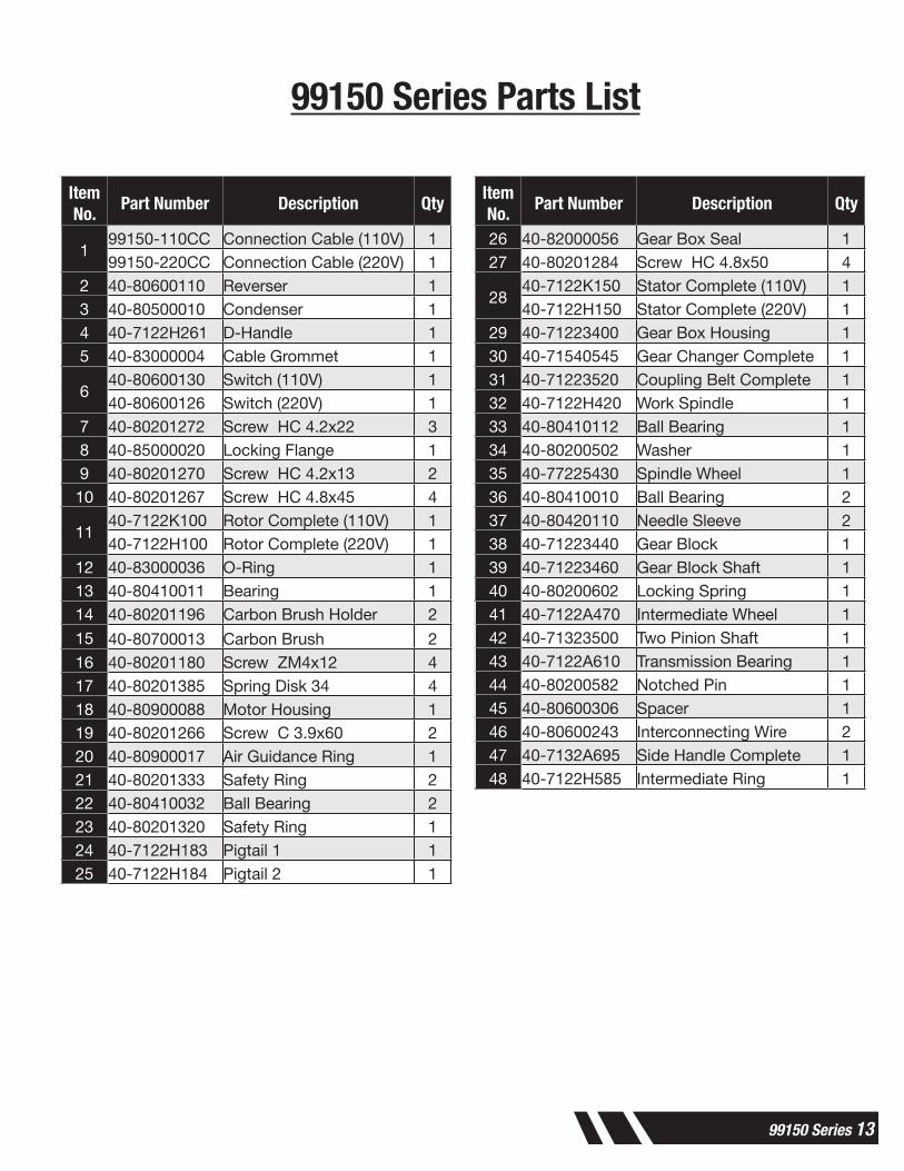
99150 Series Parts List
Item No.
Part Number Description Qty
199150-110CC Connection Cable (110V) 199150-220CC Connection Cable (220V) 1
2 40-80600110 Reverser 13 40-80500010 Condenser 14 40-7122H261 D-Handle 15 40-83000004 Cable Grommet 1
640-80600130 Switch (110V) 140-80600126 Switch (220V) 1
7 40-80201272 Screw HC 4.2x22 38 40-85000020 Locking Flange 19 40-80201270 Screw HC 4.2x13 210 40-80201267 Screw HC 4.8x45 4
1140-7122K100 Rotor Complete (110V) 140-7122H100 Rotor Complete (220V) 1
12 40-83000036 O-Ring 113 40-80410011 Bearing 114 40-80201196 Carbon Brush Holder 2
15 40-80700013 Carbon Brush 216 40-80201180 Screw ZM4x12 417 40-80201385 Spring Disk 34 418 40-80900088 Motor Housing 119 40-80201266 Screw C 3.9x60 220 40-80900017 Air Guidance Ring 121 40-80201333 Safety Ring 222 40-80410032 Ball Bearing 223 40-80201320 Safety Ring 124 40-7122H183 Pigtail 1 125 40-7122H184 Pigtail 2 1
Item No.
Part Number Description Qty
26 40-82000056 Gear Box Seal 127 40-80201284 Screw HC 4.8x50 4
2840-7122K150 Stator Complete (110V) 140-7122H150 Stator Complete (220V) 1
29 40-71223400 Gear Box Housing 130 40-71540545 Gear Changer Complete 131 40-71223520 Coupling Belt Complete 132 40-7122H420 Work Spindle 133 40-80410112 Ball Bearing 134 40-80200502 Washer 135 40-77225430 Spindle Wheel 136 40-80410010 Ball Bearing 237 40-80420110 Needle Sleeve 238 40-71223440 Gear Block 139 40-71223460 Gear Block Shaft 140 40-80200602 Locking Spring 141 40-7122A470 Intermediate Wheel 142 40-71323500 Two Pinion Shaft 143 40-7122A610 Transmission Bearing 144 40-80200582 Notched Pin 145 40-80600306 Spacer 146 40-80600243 Interconnecting Wire 247 40-7132A695 Side Handle Complete 148 40-7122H585 Intermediate Ring 1

14 99150 Series
Technical Information
Rated Voltage: 110V / 120V (99150-110) 220V / 240V (99150-220)Rated Power Input (Watts): 1100Frequency: 50 – 60 HzMax. Amperage: 10A (110V) 5A (220V)ELC110220 Limit Setting: 500 (110V) 250 (220V)Free Speed (No Load): 760 (Low Gear) / 1250 (High Gear)Max. Torque (Ft.-Lbs. / N*m): 8 / 10.8 @ 690 RPM (High Gear) 12 / 16.3 @ 290 RPM (Low Gear)Protection Class: II (Double Insulation)Degree of Protection: IP 20Interference Suppression: as per DIN VDE 0875, EN 55014
All rights of changes due to technical development reserved.
Dimensions (without toolbox):Length (Inches / mm): 18 / 457.2 Width (Inches / mm): 8 / 203.2 (w/ Side Handle)Height (Inches / mm): 5.5 / 139.7Weight (Lbs. / Kg): 9.3 / 4.2
Dimensions (with toolbox):Length (Inches / mm): 20 / 508 Width (Inches / mm): 10.5 / 266.7Height (Inches / mm): 10 / 254Weight (Lbs. / Kg): 11.3 / 5.1
Noise Emission:Noise emission figures are based on DIN 45 649, part 2, DIN 45 635, part 21, and DIN EN 27 574 (ISO 7574).
- noise level (LWAc) (94+3) dB re 1 pW
working place-related emission figure (LpA) 84 dB per DIN 45635 – 21 – KL 2
- noise level (LWA) 88 dB re 1 pWworking place-related emission figure (LpA, cyc) 79 dB per DIN 45635.

WARRANTYShould any part, of Seller’s own manufacture, prove to have been defective in material or workmanship when shipped (as determined by Seller), Seller warrants that it will, at its sole option, repair or replace said part f.o.b., point of manufacture, provided that Buyer notifies, in writing, of such defect within twelve (12) months from date of shipment from the manufacturing plant.
On request of Seller, the part claimed to be defective will be returned, transportation, insurance, taxes and duties prepaid, to the factory where made, for inspection. Any item, which has been purchased by Seller, is warranted only to the extent of the original manufacturer’s warranty to Seller. Seller shall not be liable for any damages or delays caused by defective material or workmanship.
No allowance will be made for repairs or alterations made by others without Seller’s written consent or approval. If repairs or alterations are attempted without Seller’s consent, Seller’s warranty is void.
THE WARRANTIES PROVIDED IN THE OBLIGATIONS AND LIABILITIES OF SELLER HEREUNDER, AND THE RIGHTS AND REMEDIES OF BUYER HEREUNDER ARE EXCLUSIVE AND IN SUBSTITUTION FOR, AND BUYER HEREBY WAIVES ALL OTHER WARRANTIES, GUARANTEES, OBLIGATIONS, CLAIMS FOR LIABILITIES, RIGHTS AND REMEDIES, EXPRESS OR IMPLIED, ARISING BY LAW OR OTHERWISE, INCLUDING BUT NOT LIMITED TO THE IMPLIED WARRANTY FOR MERCHANTABILITY AND FITNESS FOR PURPOSE. Seller’s total liability is limited to the lower of the cost of repair or replacement.

Elliott Tool Technologies, Ltd. 1760 Tuttle Avenue Dayton, Ohio 45403-3428Phone: +1 937 253 6133 • +1 800 332 0447 Fax: +1 937 253 9189www.ell iott-tool.com
Printed in the USA© 05/2018 Elliott Tool Technologies, Ltd.TM-106
Elliott Tool offers a complete line of precision tube tools to meet your needs. Contact us or your local support.
Contact Us
www.elliott-tool.com/support
Locally Supported By:
Related Documents


![ROBERT JAMES ELLIOTT CURRICULUM VITAE CITIZENSHIP ...haskayne.ucalgary.ca/.../robert-elliott-cv.pdf · R.J. Elliott – CV [September, 2006 - Page 1] ROBERT JAMES ELLIOTT CURRICULUM](https://static.cupdf.com/doc/110x72/5fdc51cfa239fb15507e657b/robert-james-elliott-curriculum-vitae-citizenship-rj-elliott-a-cv-september.jpg)

