AIAA 99-2951 THE 260 - THE LARGEST SOLID ROCKET MOTOR EVER TESTED P. Criinmins, M Consineau, C. Rogers and V Shell Gei~corp Aerojet Sacramento, CA 35"' AIAAIASMEISAEIASEE Joint Propulsion Conference and Exhibit 20-24 June 1999 Los Angeles, California Shuckelford 1 ID. Wol.k:unail.cm:~il a11;rch :AIAA ?ti0 palxl. MC- I .doc https://ntrs.nasa.gov/search.jsp?R=20000033816 2018-06-11T04:18:57+00:00Z

Welcome message from author
This document is posted to help you gain knowledge. Please leave a comment to let me know what you think about it! Share it to your friends and learn new things together.
Transcript

AIAA 99-2951
THE 260 - THE LARGEST SOLID ROCKET
MOTOR EVER TESTED
P. Criinmins, M Consineau, C. Rogers and V Shell
Gei~corp Aerojet
Sacramento, CA
35"' AIAAIASMEISAEIASEE Joint Propulsion
Conference and Exhibit
20-24 June 1999 Los Angeles, California
Shuckelford 1 ID. Wol.k:unail.cm:~il a11;rch :AIAA ?ti0 palxl. MC- I .doc
https://ntrs.nasa.gov/search.jsp?R=20000033816 2018-06-11T04:18:57+00:00Z
AlAA 99-2951
THE 260 - THE LARGEST SOLID ROCKET MOTOR EVER TESTED
P. Crirnmins, M. Cousineau, C. Rogers and V. Shell Gencorp Aerojet P 0 Box 13222
Sacramento Ca 958 13-6000
Abstract
Acrojet in the mid 1960s. under contracc to NASA. built and static hot fire tested the largest solid rocket motor (SRM) in history for h e purpose of demonstrating the feasibility of utilizing large SRMs for space. exploration. This program successfully fabricated two high strength stccl chambers, loaded each with approximately 1.68 million pounds of propellant, and static test fired these giants with their nozzles up from an underground silo located adjacent to the Florida everglades. Maximum thrust and t o d impulse in excess of 5,000,000 lbf and 3,470,000,000 Ibf-sec were achieved. Flames from the
7. Motor Ignition
8. Engineering the project over 3000 miles away from the fabrication, casting and inspection activities
This program was highly successful and NASA used some thc technology that was derived to develop the Space Shuttle SRM Boosters. This propam was con- ductcd in the infancy of solid rocketry and represented a very large undertaking as well as significant forward thinking and risk management on NASA's part.
Motor Dcscripdon
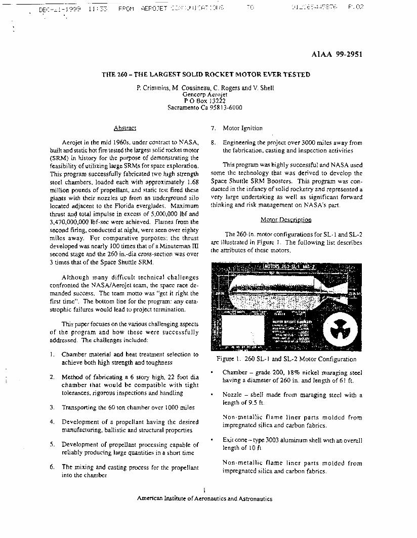
second tiring, conducted at night, were seen over eighty The 260-in. motor configurations for SL-I and SL-2
miles away. For comparative purposes: the thrust arc illustrated in Figurc I . The following list describes developed was nearly 100 times that of a Minuteman IU the atmbutes of thesc motors.
second stage and the 260 in.-dia cross-section was over 3 times that of the Space Shuttle SRM.
Although many difficult technical challenges confronted the NASAiAerojet team, the spacc race dc- manded success. Thc team motto was "get it right the first time". The bottom line for the program: any cata- strophic failures would lead to project tcrmination.
This paper focuses on the various challenging aspects of the program and how thesc were successfully addressed. The challenges included:
1 . Chamber material and heat treatment selection to achieve both high strength and toughness
2. Method of fabricating a 6 story high, 22 foot dia charnbcr lhat would be compatible with tight tolerances, rigorous inspections and handling
3. Transporting thc 60 Ion chamber over 1000 miles
4. Development of a propellant having the desired manufacturing, ballistic and structural properties
5. Development of propellant processing capable of reliably producing large quantities in a shon time
6. The mixing and casting process for the propellanr into the charnbcr
Figure 1. 260 SL- I and SL-2 Motor Configuration
- Chamber - gradc 200, 1 8% nickel muraging steel having a diameter of 260 in. and length of 61 ft.
Nozzle - shell made from maraging steel with a length of 9.5 ft
Yon-metallic f l ame l iner p a n s moldcd from impregnatcd silica and carbon fabrics.
Exjt cone- type 3003 aluminum shell with an overall length of 10 R.
Non-metallic flame l iner parts moldcd from impregnatcd silica and carbon fabrics.
1 American institute ofAeronautics and Astronautics

Nozqlelexit cone expansion ratio of 6: 1.
~ntcrflal insulation - V-44 (asbestos and silica filled nitrilk rubber).
Fo&ard and af t boots made from V-45 (silica filled nitrile rubber).
Propellant - PBAN; bore configuration was wagon wheel.
Motor Asscmhly - length of 80.7 ft. and wcight of 1,858,300 pounds.
Ignition system -30 in. dia rockct motor placed in 260 in.-dia nozzle
Initial Effon
Initial effort (circa 1963) on the 260 in. dia rocket motor program was under the cognizance of the U. S. Air Fo~ccI(AFRPL) and consisted of design and analysis studies and laboratory testing to obtain data that would be uscful in the building of the 260. The 1965 modification to the DoDfiASA agreement granted full rcsponsibiIity to NASA Lewis Rescarch (contract NAS3-6284). Despite the early changes, the 260 program is usually lhought of ac an all NASA development effort
Early'in the program the Air Force specified that Aerojet use 18% nickel maraging steel. which was an excellent material, but one for which manufacturing experience was somewhat limikd. Consequently much of the 1963 - 1965 laboratory testing was directed to its characterization (strength, toughness, weldability, cold rolling, etc.) and scale up of prior materials and proccsses to the components and assembly sizes required for the 260 in. dia rocket motor program.
Srudies leading to the use of grade 200, 18% nickel maraging 'stecl for the rockct motor were initiated at Aerojet under Air Forcc contract AF 33(657)-8740. During 1962, Aerojet reviewed a nurnbcr of different alloy steels for chamber fabrication including D6AC. AISI 4335V, 18% nickcl maraging steel (3 grades), 9Ni-4Co, 12% nickel maraging steel and HY 150 materials. The low alloy stecls werc discarded because of the need to devclop and construct very large protective atmosphe+ gantry furnace-quench and temper facilities lo heat-vent the 260 in-dia chambers. Thc 9 Ni-4Co and 12% maraging steel wcre ncw developments while the HY 150 steel, an advanced submarine hull stecl, did not meet the strength -weight requirements. Consequently 18% nickel maraging stecl was selectcd as the best
candidate and the 3 major grades, 200,250 and 300 KSI nominal yield sucngth, wcrc evaluated with regard to melting practice, material properties, welding, heat treating, forging and forming. The thrcc nominal strength levels produced by air melt, air melt plus vacuum dcgas and vacuum arc remelt werc evaluated for strength, duc~ility, fracture toughness, stress corrosion resistancc, weldability, ctc. Various solution treating temperatures (1 500- 1675°F) and aging cycles (850-950°F for 2- 1 6 hours) wcrc investigated. Weld processcs evaluated included the incn gas shielded tungsten arc (TIG); incn gas shielded metal (MIG) and submerged arc process. Typical mechanical properties obtained for parent material and weldmcnts arc shown in Figurc 2. Based on the rcsults of the program, the grade 200, 18% nickel maraging steel produced by vacuum arc remelting, welded by the TIG process and post weld aging at 900eF for 4-8 hours were selected.
Thesc materials and process studies were expanded and applied directly to the 260 in. dia chamber fabrication at Sun Ship. The technology developed at Aerojet was transferred to Sun Ship through extensive materials and process development and manufacture of subscalc pressure vessels using the processcs. tooling and cquipmcnt to bc used in the manufacture of the 260 in. dia chambers. This program assured thc complete connollability and undcrsvanding of the malerials and fabrication techniques.
Tcsts were conducted to determine the effects of temperature variations within the large agjng furnace used for post weld maraging of the monolithic 260 in.dia chambers. Weldments produced using the production equipment, processes and wcld wirc were evaiuatcd. Stress corrosion tests using various hydrotest fluids were performed and a solution of 1.56 sodium dichromatc with pH adjuslmcnt to 7.4 using sodium hydroxide was selected. Extensive machinability tests were performed to develop acceptable process parameters w d fluids for all anticipated proccsses, e. g. turning, milling. drilling. lapping, ctc.. used for manufacture. Weld repair tests to establish process parameters, number of permissible repair welds. past wcld aging cycles and fixtures, etc., wcrc conducted. Non-dcsmcti ve inspection techniques werc also evaluatcd and dcfecf containing samples of plates, forgings and weldmcnts wcre testcd to insure that the critical flaw sizes and types, determined by fracrure toughness tests and analyses could be readily dctectcd OR full scale hardware.
Thc parent metal required for this total devclopmcnt efforr at Sun Ship waq ohtained from subscale and full- scdc platcs, bars and forgings produced by our suppliers.
American hti tUte of Aeronautics and Astronautics

Note: I ) Welding by chamber manufacture processes not practical
kigure 2. 260 Typical Tcnsile ~ r o ~ e r t i e s and Fracturc Toughness of 18% Nickcl Maraging Steels
Plate sizep of 431 x 104 x 0.61 in. and ring forgings 260 &a x 32 4 3.5 in, were successfully produced and used for hardwkre manufacture. Test material from each platc and forg+g was tested for chemistry, metallurgical. tensile and toughness properties for both parent and weldmcnts over the full range of temperatures and times expec te l in the large aging furnace to cnsurc compatibrlity between plates, forging and weld wire. This total materials and process development program ended with the successful manufacture and hydroburst of two 36 in.dia process evaluation prcssure vessels. The burst tcsts a~so'~rovided biaxial properties that were uscd to verify thc'criteria and analyses used for hardware design. This extensive materials and process development ovcr approximately 18 months served to verify thc matenals. processes and equipment to be used during hardware manufacture. inspection and testing. It also provided the main aJenue to the technology required for manufactbring reliable rocket chambers in a sea coast shpbuilding environment.
Simiiar process and propellant development was conduct4 initially, and is described under Propellant and Casting sections of this paper.
Chamber Fabrication I
The fabrication of a chamber of this magnitude exceeded the capabilities of Aerojct in terms of expcricnde and facilities. Consequently Arrojet teamcd with SUD Ship and Dry Dock Co. located in the Philadelphia area. This mamagc proved beneficial in that each company brought technologics necessary for the succeks of the program. Aerojet's contributions lay in the a d s of chamber design, chamber ~natcrials and processing technology, nondestructive inspection. structural testing of the finished chamber md ovcr~ l l
rocket design experience. Sun Ship's contributions lay in the areas of handling largc metal plates, fabricating large metallic structures and having facilities, including overhead cranes, big enough KO accommodate the 22 foot dia chamber. Additionally. Sun's location on the Delaware River allowed ease of shipment via barge to the Aerojet facility in Florida.
Prior to building the first 260 in. dia chamber, a 280 in. dia chamber was fabricated using mild steel for purposes of identifying any problems relating to handling, welding, and the ability to maintain the required tight tolerances. The 280 in dia chamber was subsequentiy uscd as a warer storage tank to support hydrotcsting of the 260 in dia chambers.
A wmbinaion of cold formed segments for the dome areas, forgings for the Y-joint areas, and rolled plates for the cylinder were used in the chamber fabrication as shown in Figure 3.' All were made of grade 200. 18% nickel maraging steel. The Ladish Co. supplied the forgings. Sun Ship performed the cold forming and rolling operations. Plates used in fabricating the cylindrical sections were 408 x 102 x 0.60-in. (after extracting test coupons); two plates joined by longitudinal T'IG welds were required for each cylindrical section.
'The terminology 260 SL is used in this figure and elswhcrc in this paper. Thc SL designation indicates a short length configuration, as the full length was not required for such a demonstration program. Thc shon length motors werc approximately 80 feet long and capable of 3.5 million pounds thrust for about two minutcs. The first two SL motors tired used propellanr burning ratcs and nozzle size appropriate for full-lcngth design.
3 American institute ofAeronaulics and Astronautics
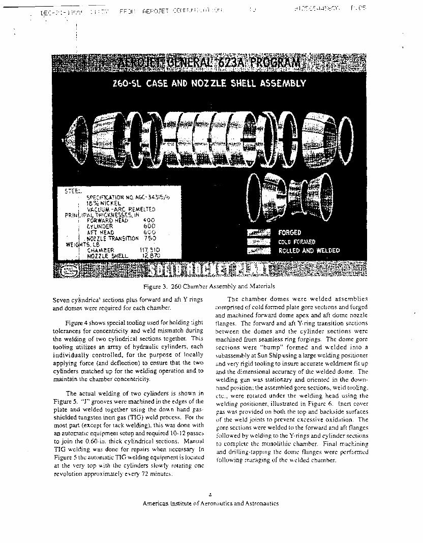
Figure 3. 260 Chambcr Assembly and Materials
Seven cyiindrical sections plus forward and a f i Y rings and domes were required for each chamber.
Figure 4 shows special tooling used for holding right tolerances for concentricity and weld misrnatch during the welding of two cylindrical sections together. This tooling utilizes an array of hydraulic cylinders. each individually controlled. for the purpose of locally applying force (and deflection) to cnswe that the two cylinders matched up for the welding operation and to maintain the chamber concentricity.
The actual welding of two cylinders is shown in Figure 5. "J" grooves were machined in the edges of the plate and welded together using the doun hand gas- shiclded tungsten incrt gas (TIG) weld process. For the most part (except for ~ a c k welding), this was done with an automatic equipment sctup and required t 0- 12 passcb to join thc 0.60-in. thick cylindrical sections. Manual TIC wclding was donc for rcpairs when ~tccessary. In Figure 5 ttlc au~on~atic TIC wclhng equipment i s locatcd at the very top with thc cylinders slowly ro~ating one rcvolutiort approximately e r q 72 minu~cs.
Thc chamber domes were welded assemblies comprised of cold formed plate gorc sections and forged and machined forward dome apex and aft dome nozzle flanges. The fonvard and aft Y-ring transition scctions hctween the d o n c s and the cylinder seclions were machined h m seamless ring forgings. The dome gore scctions were "bump" formed and welded in lo a subasserr~bly at Sun Ship using a large welding positianer and very rigid tooling to insurc accurate weldrnen~ f i t up and the dimensional accuracy of Lhc welded dome. The welding gun waq stationary and oricnted in the down- :land posirion; the assembled gore secrions, weld ~ooljng. ccc., were rotated undcr the welding head using thc welding positioner, illustrated in Figurc 6. inert cover pas was provided on both the top and backside surfaces of thc weld joints to prevenl excessive oxidation. The gore scctions wcre welded to the forward and aft flangcs iollowed by welding to the Y-rings and cylindcr sections ro cornplctc the rnonolilhic chamber Final machining and drilling-lapping the dorrlr flanges were p:rfc)rmcci following maraping of thc &clded cha~nher.
American Lnstitute of Aeron;rutics and Astrona~ltics

r . .-.* "I,. . . jg a:;. . I ' .. . ,: . . * .. . . .. .,g~it~ 2% : *,--
Figure 4. 260 Chamber Cylindrical Welding Tooling Figure 5. 260 Chamber Welding of W o Cylindrical Case Sections
All welds u,ere radiographically inspected for porosity, Raws and foreign material. Weldment X-ray parameters and acccptancc criteria for such were b a e d on the fracture analysis and material toughness, e.g. what size flaw could be tolerated without detrimental propagation during hydrotest and motor firing. Ovcr a quarter of a mile of welds were inspcctcd for each chamber.
Heat treating of the chamber was accomplished by subjecting thc chamher to 900°F for 8 hours. This was done by building a special structurc to house the chamhcr. Gas furnaces and blowcrs wcre attached to the structure and provided the heating and its d~siribution through an enclosed ducting system (no dircct flame impingcmcnt on the chamber). Thcnnocouples arrachd to the chamhcr wall provided the necessary information for controlling furnace hear and its disuibution.
Aftcr aping. thc charr~bcr was placcd vertically in thc hydrotcst s t u d and the aft boss and the tlrcadsd holes uscd for nozzle ait;ichment wcrc machined.
Nozzle Fabrication
The nozzle assembly consisted of a maraging steel nozzle shell and type 3003 aluminum exic cone structural components with flame liners. The nozzle shell had an entrance cap (welded gore sections) plus three for@ngs dl welded together using the down-hand GTWA welding process to form the convergent-divergent nozzlc shcll. The nozzle shell was finished machined (bolt holes drillcd, etc.) after the welded assembly w a heat-treated at 900°F for 8 hours. The entrance throat and the flamc liners wcre bonded internally to the nozzlc shell. The exir cone external support system wa.\ machincd from a singie type 3003 aluminum forging. The exit conc flame liner was bonded internally i o this suppon structure. All of the flamc liners were tapc wrdpped using impregnated silica and/or carbon tape, which was autoclaved cured to achicve the required densiry and propcnies. Tape wrap angles were selected t o optinuze crosion rcsis~ance and minimizc ply lifting during firing.
5 America11 Institute o f Aeronautics and Astronautics
Structural Proof Testiqg
The chambcr and nozzle were hydrostatic proof tested to a pressure of 737 psig (meazured at the highest point) for purposes of verifying their structural integrity. The forward skin waz loaded concurrent with the pres- sure load.
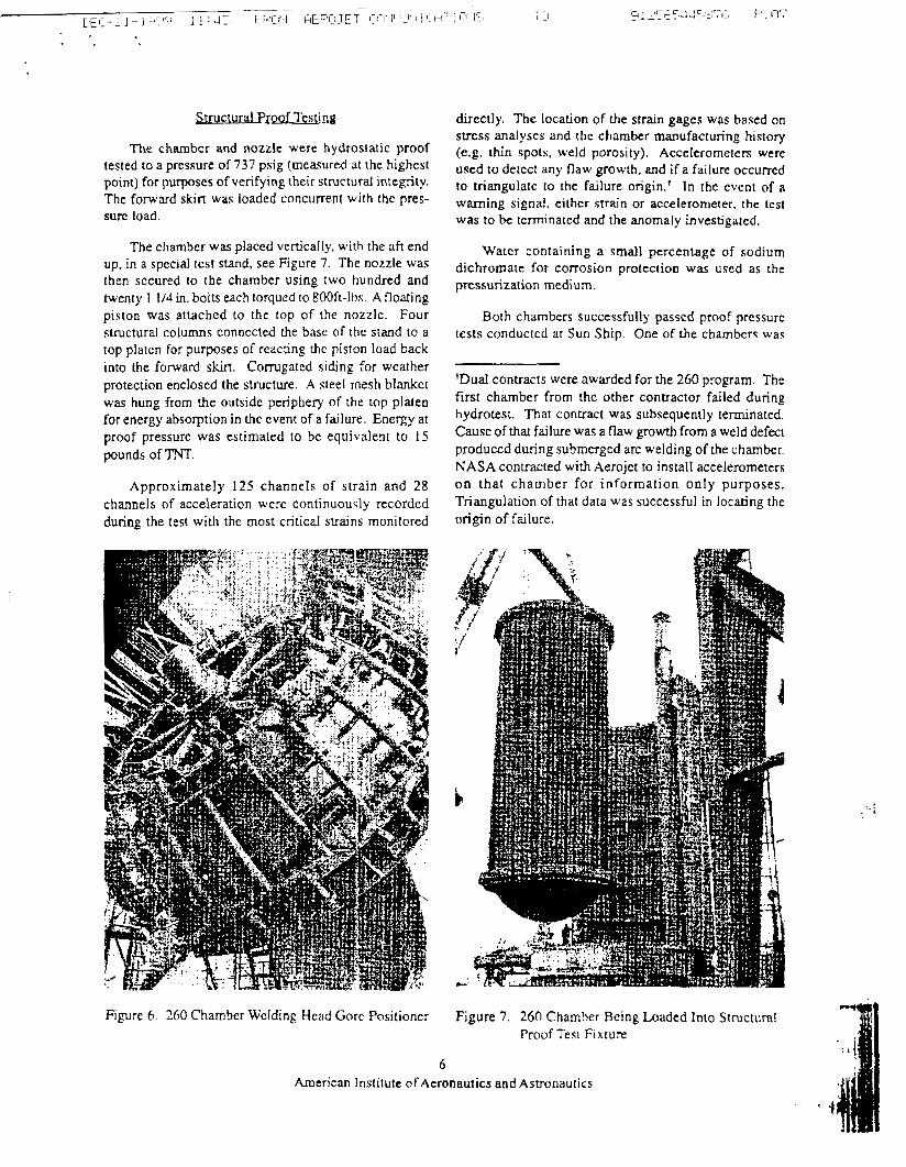
The chamber was placed vertically, with the aft end up, in a special tcst stand, see Figure 7. The nozzle was then sccured to the chamber using two hundred and twenty I 114 in. bolts each torqued to 800ft-lbs. A floating piston was attached to the top of the nozzlc. Four structural columns connected the bass of the stand to a top platen for purposes of reaccing the piston load back into h e forward s h . Corrugated siding for weather protection enclosed the structure. A steel mesh blankct was hung from the outside peripherq of the top plaen for energy absorption in thc event of a failure. Energy at proof pressure was estimated to be equivalen~ to 15 pounds of TNT.
Approximately 125 channels of strain and 28 channels of acceleration were continuously recorded during the test with the most critical strains monitored
directly. The location of the strain gages was based on stress analyses and the chan te r manufacturing history (e.g. thin spots, weld porosity). Accelerometers werc used to detect any flaw growth, and if a failure occurred to triangulate to the failure origin.' In the event of a warning signal. either strain or accelerometer. the test was to be tcrrninatcd and the anomaly investigated.
Water containing a small percentage of sodium dichromate for corrosion protection was ~ised as the pressurization medium.
Both chambers successfully passcd proof pressure tests conducted at Sun Ship. One of the chambcrs was
'Dual contracts were awarded for the 260 program. The first chamber from the other contractor failed during hydrotest. That contract was subsequently terminated. Cause of that failure was a flaw growth from a weld defect produced during submerged arc welding of the chamber. KASA contracted with Aerojet to install accelerometers on that chamber for information only purposes. Triangulation of that data was successful in locating the origin of failure.
Figure 6 260 Chamber Welding Hcad Gorc Positioner Figure 7 . 260 Chamber Being Loaded Into Structuml Proof Test Fixture
6 American institute of Aeronautics and Astronautics

reused for the 260 SL-3 static firing. This chamber was hydrostatic tested at Dade County Florida in a slightly different manner. It was placed in thc underground silo and the nozzlc capped.
Transmnation to Cast Site
Following hydrotest the chambers wcrc painted and then placed on a barge, Figure 8, for transport down the inter coastal waterway to Florida. The tra11sport for thc final few miles from where the waterway ended was by truck and trailcr. During ;he transport of thc second chamber the bargc encountered a hurricane and was beached. Fortunately the chamber support was designed to lake out torsional loads and the chamber was undarnaped.
Figure 9. 260 Motor Cast Configuration
Other facilities included a general processing building, a quality control laboratory, a fuel preparation building, an oxidizer preparation building, a qualification motor building, continuous mix building. two vertical batch mix stations and a remote conlrol house ro support static testing.
Constructing roads throughout thc plan1 required f i l l dirt, and the most convenient place to obtain this was adjacent to the road. Consequently there was a series of "canals" next to most roads. Some of the best bass fishing in Florida were at these "canals". However, bass were not h e only inhabitants, and i t came to pass that alligator
--
crossing signs were required along cenain suctches of F i p r c 8. 260 Chamber Bcing Trdnsported to
the roadway. Aerojet's Florida Rocket Facility
J%c Florida Dade Countv Facjliry
In anticipation of the 260 program and futurc booster contracts Aerojet acquired a site south of Miami and adjacent to the everglades. This site (approximately 74,000 acres) was about 250 miles south of Cape Canaverai, and both were accessible by barges. In parallel with designing the motor, work began on thc huge facil i t ies requircd for the motor and propellant production, static test firings, and supporting acrivities. The overall concept was that the chamber wrould bc insulated in the horizontal attitude and then lowered nose first into a below ground silo, illustrated in Figurc 9. with the nozzle at ground lcvel Propellant casting and cure, core removal, nozzle asscrnbly and tcst firing was done in this vedcal nou lc up position in the undcrgmund silo. This silo was constructed to accommodate a full-length motor. Thcre was a prcat deal of concern abour the silo becoming flotded sincc the ground level wils essen~ially sea level. ' f ic 150-ft. depth proved to be no problem for a cornpctent caisson contractor.
An office building for the permanent staff was located in Homestead approximately 1 2 miles away.
Insulating the Charnbe~
V-44, an asbestos and silica filled Ritrile tubber. was used to thermally insulate the chamber cylindrical and dome walls. Sheets of the insulation were bonded to the chamber interior using a room temperature curing bonding systcm. This was donc in a series of steps with the chamber in the horizontal position. In the case of the domes the sheets of insulation were cut to form gore sections. V-45 silica filled nitrile rubber boots (also called flaps) were installed in the forward and aft ends in the area of the equaors.
Propellant and lincr formulation and process dcvclopment work conducted at thc Sacramento facility Icd to the selection of an 86% solid PBAN propellant for thc motor. Extensivc processing and cured pmp~1fBR1 '" testing was conductcd on propcllmt from small atid ffilflt
7 American Institute of Aeronautics and Astronautics

scale batches and then full scale batches. Tests included pot life, viscosity. cure, chemical and physical propcrtics of cured and uncured propellant. ballistics, mechanical and bond properties. Comprehens4ve mechanical and propellanr-liner bond tests wcre performcd to determine allowable properties and full scale motor structural margins. Many of thc tests wcre repeated on thc propellant produced at Dade County.
The size of the 260 in. dia motor and the processes selected for producing the motor imposed a number of unique requirements, some of which werc time related on the propcllant and liner bonding system. Among those requirements were: long propellant liner bonding life, low propellant viscosity, long propellan[ pot life and steady state cure of the propellant.
For the 260 SL motor a liner substrate was required to bond the propellant grain to the rubber thermal insulator. A liner bonding life' of several months was essential for the motor process. Typical liner bonding lives are in the order of days. The PBANIepoxy developed for the motor satisfied all of the processes as well as all bond strength requirements.
The motor was cast using a bayonet cast process which involved forcing the propellant down a 6 in. dia hose from the cast pot into the motor. This process required a propellant having both a low viscosity and a long pot life.
Many sorid propellants never re.ach a stcady state- of-cure. When held at the cure temperature, they increase in modulus with an attendant decrease in elongation and strain bcaring capability. Such behavior is highly undesirable for a large motor which requires 2-3 weeks to cast, since it would cause significant mechanical property gradients in the propellant grain. The 260 SL-1 and -2 propellant reached a steady state-of-cure after three weeks thus minimizing such gradients.
The Dade County mix facilities consisted of two 600-gal. Day vertical mixers and an UK-200 continuous mixer. All mixers were used in loading rhc 260 in. dia motors.
Propellant reproducibility and predictability werc cssential to a successful motor firing. Thcse objectives were met by utilizing singlc propcllant raw material lots
(or master blends) for each of the motors and by conducting lot standardization tests with each new lor by testing thc propcllant produced in production mixes prior to each motor cast. Laboratory acceptance testing was performed on all raw materials before use and on all process intermediates and uncured propellant before casting. Mcchwical propeny tes~s werc performed O H cach batch after cure, and ballistic test motors werc fired.
To preparc for cast aftcr chamber placement in the underground silo, core tooling was installcd. the roller mounted cast building movcd over thc silo. casr tooling sct up and motor preheated to the cure temperature. When thc loaded propellant pots arrived from the mix stations they were hoistcd to one of three cast stands. 6-in. d j a hoses, or bayonets, were attached to each pot and the propcllant was forced down the hoses. The hoses were shortened as the propellant level rose. ?\vo to three weeks wcre required to complete the casting process. The gralii was then cured for approximately three weeks. The propellant grain as viewed from the top is shown in Figure 10.
After cure the motor was cooled to ambient tcmperature, the cast building moved and the core stripped. The bore of the grain was then visuallj inspectcd for defects; no significant ones were found for 260 SL-1 and -2 but were found for 260 SL-3.
A concern carly in the program was whether during core su-ipping tbe propcllant grain lobes would slump, thus binding against the core and making.irs removal clifficult. Laboratory slump tests were not conclusive. A take-apart core was designed to avoid this possible problem. The core was easily removed in one piece so that this precaution was not needed.
Ipniticm Svstem
A non-conventional ignition system was employed for the 260 dcmonsmtion firings and consisted of placing a 30 in. dia rocket motor in the nozzle of the 260. t h t 30 in. dia motor was anached to a sled, which iH 1UR was mounted to a track so that when the igniter t i ~ t t l F fired its thrust carried it and the sled up the track, ad away from the 260 motor. Two long 2 'h in cables, attached to thc sled and secured to the ground, forced the sledlmotor into a circular orbit once the sledlmotor clearcd the track. The igniter motor provided penetration of gascs to approximately 7 0 8 of the motor bore Icng~ll.
260 SI .-!-ad SL-2 Static F i r i w . b
?Liner bonding life is defined as the timc intend berwccn The first and beand static test firings vet$ @flf#m.,
cure of the liner LO contact with the propellant in thc motor. on Septembcr 35, 1965 and February 23, 15166 (ill night)
8 American Institute of Aeronautics and Asvonautics

Figure 10. Top Vicw of 260 Motor Grain Configuration
and were totally successful. Performance was necly identical for thc two firings with the maximum thrust and total impulse being 3.6 million pounds force and 375,000,000 pound seconds respectively. Thc thrust time curvc is shown in Figure 11. Figure 12 shows the firing of 260 S L 1. As noted previously the propellant burning rate and nozzle sizing was similar to that which would be used in the full-length configuration.
Figure I I . 260 SL Hor Fire Test Results Wf4' c 9
American institute ofAeron
260 SL-3 Static Firirg
NASA contracted witb Aerojet for a third 260 sletlc i
firing with the primary objectives of:
Testing a large ablative nozzle using a suhmergtd nozzle configuration similar to that proposed for t izP
with thrust vector control systems
Demonstrating a PBAN propellant fbfFH~11 an increased bum rate from 0.45 to tl:q$ duplicate full-length mass flow rates
The 260 SL- I chambcr was rehabilitared (incl~~dii!P )of test) for the SL-3 firing.
The 260 SL-3 rnoror fired on June 17, 1967 A maximum lhrust in excess of5 pounds rhtusl Wile achicved. However b e tesl was not a total suctP98 I R that chunks of prop ell an^ wcre ejected which loss of the c x i ~ cone in the latter ponion oi Based on observations during castit# Wid k anomalies after core stripping, it was c o n c i ~
autics and Astronautics
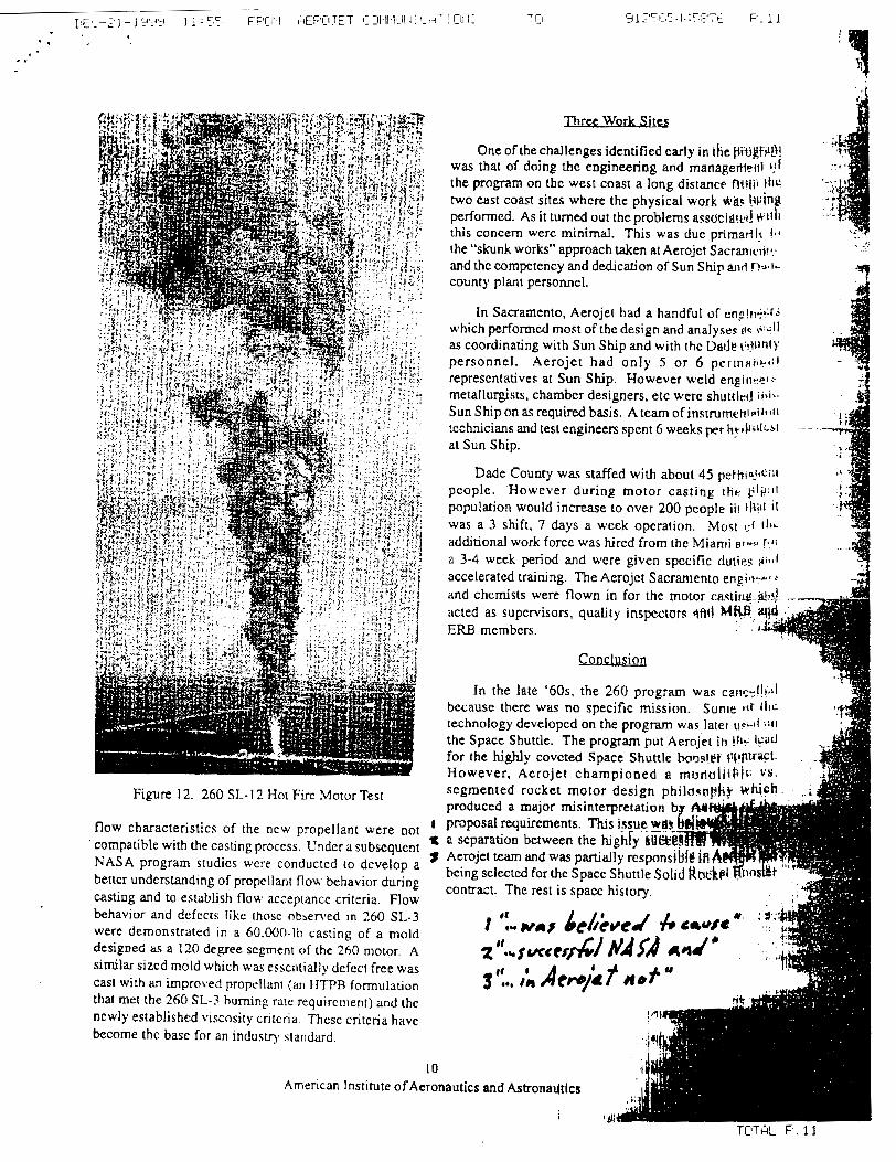
Figure 1 2. 260 SL- I ? Hot Fire Motor Test
flow characteristics of the ncw propellant were not I
' compatible with the casting process. Under a subsequent t NASA program siudies wcre conducted to develop a 9 beucr understanding of propellant flow behavior during casting and to establish flow acceptance criteria. Flow behavior and defects like thosc obsenred In 260 SI,-3 were demonstrated in a 60,000-lb casting of a mold designed i ~ r a 120 degree s c l e n t of the 260 motor. A sirnilarsizcd mold which was essentially defect free was cast with an impro\,ed propellanr (an IITPB formulation Lhal met the 260 SL-3 burning rare requirement) and the newly established viscosity cntcria. Thesc critcria have become thc base for an industq standard.
10 American Institute ofAeron
Three work Sites J One of the challenges identified early in ihe Ptti#fl&!
was that of doing the engineering and rnanagerif~i~l the program on the west coast a long distance M?iii the '
two cast coast sites w performed. As it Lurne this concern were mi the "skunk works" and thc compctency and d d c a t i o n of Sun Ship and ~ . J . I -
county plant personnel.
In Sacramento, Aeroj which performed most o f t as coordinating with Sun Ship and with the Ddtjr t:!Jl!no' personnel. Aerojet had only 5 o r 6 p e r l n n r l k * ~ ~ representatives at Sun Ship. However weld engi11t.i.r.- metallurgists, chamber designers, etc were shuttled i i J -
Sun Ship on required basis. Ateam of i n s t r u m e t ~ ~ ~ i ~ * ~ ~ ~ technicians and test cngineers spent 6 weeks pr hF.,li+bI~bl --- - -
at Sun Ship.
Dade County was st people. However during motor casting tHe C;ISI~I population would increase to over 200 people it! lk;tt
was a 3 shift, 7 days a week opcration. h.lost t:f 1111.
additional work force was hired from the Mianri s t - c J i b l i
a 3-4 week period and wcre given spccific duties di-i accelerated training. The Aerojct Sacramento engill-as a
and chcmists were f l acted as supervisors, qu ERB members.
Conclusiorl
In the late '60s, the 260 program was ca~ir r f ! .~ l l because there w a ~ no specific mission. S u n ~ e H r iilc technology developed on the program was later uc~l! ~ 1 1 1
the Space Shuttle. The program put ernj jet ih !!I+ 1:ild
for the highly coveted Space Shuttle booslef V C ~ f l t ~ % t . . - However, Acrojet championed a rnt,ricriilbir: c.8.
segmented rocket mot produced a major misinterpretati proposal requirements. Ths issue a separation between the hjghry b Aerojet tearn and was partially responsl bcing sclectcd for thc Spacc Shuttle Soli contract. The rest is spacc history.
r ':.. vr l CI.//iucd k LIW. : s ' z "- u r c tr&l NAgA w d st!.. ;; Acrr/i f r e f "
autics and Astronadtics
TOTAL P . 11
Related Documents


![Rocket! :]](https://static.cupdf.com/doc/110x72/558c01cdd8b42abd5b8b4570/rocket-.jpg)

