NASA Technical NASA-TP- 1937 19820006403 Paper . _ 1937 December 1981 Interactive Design and Analysis of Future Large Spacecraft Concepts L. Bernard Garrett

Welcome message from author
This document is posted to help you gain knowledge. Please leave a comment to let me know what you think about it! Share it to your friends and learn new things together.
Transcript

NASATechnical NASA-TP- 1937 19820006403
Paper . _1937
December 1981
Interactive Design andAnalysis of Future LargeSpacecraft Concepts
L. Bernard Garrett

3 1176 00519 4734

NASATechnicalPaper1937
1981
Interactive Design andAnalysis of Future LargeSpacecraft Concepts
L. Bernard GarrettLangley Research CenterHampton, Virginia
NI_ANational Aeronauticsand Space Administration
Scientific and TechnicalInformation Branch

The use of trade names in this publication does not
constitute endorsement, either expressed or implied,
by the National Aeronautics and Space Administration.

ABBREVIATIONS
ACS attitude control system
ACTD active damping
AMCD Annular Momentum Control Device
ANALOG Analogous Modeling (module)
AVID Aerospace Vehicle Interactive Design (program)
CP central processing
CRT cathode ray tube
DYLO Dynamic Loads (module)
GTS General Truss Synthesizer (module)
Isp specific impulse
LASS Large Advanced Space Systems
LASSDB LASS data base
MRS microwave radiometer spacecraft
POST Postprocessor (module)
RCD Rigid-body Control Dynamics (module)
RCS reaction control system
RF radio frequency
rms root mean square
SA Surface Accuracy (module)
SAP Structural Analysis Program
S/C Spacecraft
TA Thermal Analysis (module)
TTSS Tetrahedral Truss Structures Synthesizer
iii


SUMMARY
An overview is presented of an interactive computer-aided design program used to
perform systems-level design and analysis of large spacecraft concepts. The primary
emphases are on rapid design and analysis of integrated spacecraft, including auto-
matic spacecraft modeling for lattice (trusslike) structures. Capabilities and per-
formance of the twenty-some multidiscipline applications modules, the executive and
data management software, and graphics display features are reviewed. A single user
at an interactive terminal can create, design, analyze, and conduct parametric
studies of Earth-orbiting spacecraft with relative ease. The approach is partic-
ularly useful in the conceptual design phase of advanced space missions when a
multiplicity of concepts must be evaluated in a cost-effective and timely manner.
Data generated in the design, analysis, and performance evaluation of an Earth-
orbiting large-diameter (750-m) antenna satellite are used to illustrate current
capabilities. Computer run time statistics for the individual modules quantify the
speed at which modeling, analysis, and design evaluation of integrated spacecraft
concepts can be accomplished in a user interactive computing environment.
INTRODUCTION
Large space systems on the order of hundreds of meters in size are projected to
become operational in the future. The sizes will be determined by one or two prin-
cipal considerations: economy of scale (e.g., antenna or sensor farms mounted on
platforms with shared central utility supporting subsystems) or advanced systems
which require large physical areas (e.g., high-power solar arrays or remote sensing
microwave radiometer antenna systems). These future spacecraft, unlike today's
spacecraft which are generally enclosed monocoque structures with a few appendages,
will have large expanses of lattice (trusslike) structures with hundreds or thousands
of individual connecting members. The lightweight, flexible structures will be sub-
jected to on-orbit environmental loads (gravity gradient, thermal, low-frequency
transient vibrations, etc.) which usually were ignored in past spacecraft designs.
Unless efficient design and analysis capabilities are developed for these advanced
structures, the engineers will be severely taxed by the modeling, design, and anal-
ysis effort.
The purpose of this paper is to describe an efficient computed-aided design and
analysis capability which has been developed to relieve the engineer of much of the
effort required in the past. Automated capabilities can be used to rapidly synthe-
size, evaluate, and determine performance characteristics and costs for future large
spacecraft concepts. The Large Advanced Space Systems (LASS) computer-aided design
and analysis program (ref. I) is used to illustrate the power, efficiency, and versa-
tility of the approach. Although the LASS capabilities are by no means complete, the
program represents an initial effort to use interactive data-processing capabilities
and spacecraft-systems-analysis-oriented software to guide the design of future large
space systems.
The coupling of space environment modeling algorithms with simplified analysis
and design modules in the LASS program permits rapid evaluation of competing space-
craft and mission designs. The approach is particularly useful in the conceptual

design phase of advanced space missions when a multiplicity of concepts must be
considered before a limited set can be selected for more detailed analysis.
Integrated spacecraft systems-level data and data files are generated for subsystem
and mission reexamination and/or refinement and for more rigorous analyses.
COMPUTER-AIDED DESIGN AND ANALYSIS CAPABILITIES
LASS Program Overview
The LASS program consists of twenty-some multidiscipline applications modules
that include structural, thermal, and control system modeling; on-orbit static,
dynamic, and thermal loading analyses; structural element design; surface accuracyanalysis and cost approximations. The modules reside on both mainframe (Control Data
CYBER 175 computer) and minicomputer (Prime 750 computer) systems. The modules are
executable from remote interactive graphics terminals. Data files are transferable
between the two computer systems. Processing and data control are accomplished via
simple efficient executive and data-base programs and file management routines. User
prompts for file names and unformatted data inputs are provided. CRT graphic dis-
plays of finite-element models and of summary information (temperature contours,
element loading histograms, mode shapes, etc.) are presented to the user for imme-
diate assessment and interactive modification of the spacecraft and/or mission asnecessary.
Discussion of Capabilities
The primary LASS modules and basic functions of each module are shown in fig-
ure I. The Aerospace Vehicle Interactive Design (AVID) program, developed by Wilhite
(ref. 2), provides executive control and data-base management capabilities for LASS.
Additional procedure files and data file management routines reside in the individualLASS modules.
LASS was developed for multidiscipline spacecraft systems analysts as opposed
to single discipline specialists or computer systems experts. The executive,
data-base/file management routines, and applications modules were selected to providea rapid, cost effective computer-aided design and analysis capability for future
large spacecraft systems concepts. The program is user friendly, prompting the
analyst with queries or requests for information such as unformatted input data, file
names, and processing paths. The applications modules have been integrated to pass
compatible, properly formatted files and data-base information between single
discipline programs. The creation, unbundling, and reformatting of data aretransparent to the user.
LASS, operating in conjunction with AVID, keeps the user well informed on the
status of data in the data base or in the permanent files. Data which were created
external to an individual application program are displayed for user modification if
desired. Variables missing from the data base are flagged with a nonfatal error
message, permitting the user to input the desired values. New input variables not
required by previous modules are input or modified by the user at the interactive
terminal. Data that are more or less constant for each new case are defaulted in the
modules with user override capabilities. Finally, data which are created from an
individual application module and required by any subsequent module are written to a
properly formatted file for immediate execution by the subsequent module or are
reformatted by the later module in a manner which is transparent to the user. Data
2

created on one computer system can be transferred to another computer system for
execution of another applications module. For example, files created on the mini-
computer can be automatically reformatted and transferred to the mainframe computerfor a batch execution of the Structural Analysis Program (SAP). Upon completion of
the run, the SAP output files can be accessed on the minicomputer for continuation of
the interactive processing session.
Executive Program
The small AVID executive program (50 to 100 lines of coded instructions) allows
the analyst to run the applications modules individually or in any desired sequence
by menu selection. The menu of spacecraft programs currently available is shown intable I. All modules are set up to run in the interactive mode except for the ones
prefaced with the word batch and the static and dynamic structural analysismodules. Note that all batch modules with the exception of the structural analyses
modules have an interactive counterpart. Only the structural analyses modules have
to be run in the batch mode because of the Langley Research Center 70 000-word memory
interactive constraint for the mainframe computers. (Typical structural models ana-
lyzed to date require 150K to 200K memory for these modules.) The minicomputer
system does not have this constraint.
The interactive design process begins with the user simply entering a string of
single characters associated with the desired program sequence. The AVID system then
automatically sets up all commands to the computer operating system such as calling
sequences, data-base and file attachment, program run commands, and return of the
system to user control. This use of executive program capabilities and internal
procedure files frees the analyst from details of computer operation and system
protocol and lets him concentrate exclusively on the spacecraft design tasks. Theseautomated features also eliminate unnecessary repetitious effort each time the mod-
ules are run; thereby, input errors and throughput time are reduced.
Data-Base and File Management Systems
The AVID data-base manager program shown in figure I can be used for editing
data either on a variable-by-variable basis or for specialized updates of larger
quantities of data. In normal LASS operations, this program is not utilized sincedata base and files are automatically created and updated by the individual applica-
tions modules.
LASS uses a combination AVID data-base program and file management routine
internal to the various applications modules to create, modify, store, and retrieve
data and to transfer appropriately formatted data between the applications modules.Data are stored either in the AVID data base (which is used for single variables or
small arrays, up to a total of 1024 variables) or in LASS user nameable permanent
files. The LASS file structure showing the required input and output files associ-
ated with each applications module is shown in figure 2. LASSDB refers to the data-
base file, all other acronyms refer to permanent file names. Default names are shown
also; however, the user may uniquely name any file with a six-character alphanumeric
designation. Each module is set up to prompt the user to specify the names of all
required input and output files. Files or data-base parameters are updated at the
completion of each module if the uder specifies the same name for the output files
3

as for the corresponding input file. If the file names are different then each file
is stored separately for later use, modification, or removal by the user.
Normally, it is easier to start a design process with previously created data
base and files and simply modify the input variables as needed at the terminal than
to start with all zero or default variables and create every input variable anew.
This is an effective labor-saving approach particularly in parametric analyses from a
given baseline (such as spacecraft size, orbital altitude, material perturbations,
and change-out of a single subsystem).
LASS Applications Modules
The Tetrahedral Truss Structures Synthesizer (TTSS), ANALOG, and the General
Truss Synthesizer (GTS) modules allow the user to create the finite-element model of
the spacecraft structure, design the structural members and hardware components, add
the supporting subsystems, and calculate the mass and inertia properties of the
spacecraft.
TTSS.- The Tetrahedral Truss Structures Synthesizer module, developed by
W. D. Honeycutt of the General Dynamics Corporation, Convair Division, is used to
rapidly model flat or curved tetrahedral truss structures and to initially size the
structural members. The module automatically generates the nodal geometry; the mem-
ber connectivity, cross-sectional areas, and masses; and the resultant finite-element
model of the structure for a specified dish diameter, shape, number of bays, and a
diagonal angle which defines the truss depth. The tetrahedral truss configuraton
definition and major hardware components are shown in figure 3(a).
The truss structural members are assumed to be circular tubes, isogrids, or
triangular truss struts as shown in figure 3(b). The surface and diagonal members
are sized separately for Euler buckling from input material properties and initial
loading conditions. Upper and lower surface members are pinned; diagonal elements
may be pinned or clamped at the user's option. Structural members can be constrained
to minimum material thicknesses and tube diameters so that the column buckling equa-
tions will not design members too small for practical use. An option also permits
the sizing of the member (diameter and thickness) from user-specified length over
radius of gyration and a tube radius over thickness inputs.
The folding hinges, spiders, bearings, and end fittings masses are computed as
functions of the structural member diameter. A mesh reflective surface and the sup-
port system may be optionally included in the calculations and is automatically dis-
tributed at each nodal point on one of the surfaces. The mesh control system, used
to maintain contour is computed as a percentage of the mesh weight. A contingency
mass is included which is defined as a percentage of the mass of all the structural
components.
Forty-five input variables as shown in table II are needed to run TTSS. The
module calculates and outputs the mass of the structural components, mesh system and
total system; the center of gravity; and mass inertia properties. The displayed
outputs also include structural member dimensions, hardware part counts, unit masses,
total group masses, mesh area, and configuration packaging dimensions for inward and
outward folded deployable surfaces. Uniquely nameable data base and files, including
a complete finite-element model of the tetrahedral truss, are created in TTSS forlater use in other modules.

In about 5 wall-clock min on the minicomputer, TTSS can detail all 6864 struts
of a 32-bay tetrahedral dish of any diameter, curvature, and truss depth, size the
structural members, incorporate all joints, pins, hinges, reflective mesh systems,
display the output summary data and the structural finite-element model, and write
the data-base/file information to LASS retrievable permanent disk storage. An eight-
bay case (420 elements) can be completed in I to 2 wall-clock min on the minicomputer
or in 6 wall-clock min using 27 sec of CP time on the mainframe computer. It should
be noted that the use of the minicomputer reduces wall-clock times by factors of 5 to
10 because of the higher data transmission rates provided with this system (9600 baud
on the minicomputer versus 1200 baud on the mainframe) and because the modules are
not rolled in and out of core as they are in the Langley mainframe computer system
during heavy usage periods.
ANALOG.- The ANALOG module is a preprocessor for TTSS and permits a large number
of tetrahedral truss members in a flat platform or curved dish truss to be replaced
for analysis by a smaller number of equivalent members, as illustrated in figure 4.
The approach and transformation equations, developed by Leondis (ref. 3), are basedon the use of a set of Constitutive Relations (stiffness characteristics) for repeat-
ing platelike lattice structures such as a tetrahedral truss. Member sizes and
geometry, physical properties, and loads are transformed in such a manner as to
retain the equivalent strength, stiffness, mass, inertia, and thermal characteristics
of the original structure. The original dish diameter and truss depth are retained
in the analogous model. The analogous modeling capability is particularly useful for
rapid parametric analyses. For example, a single pass through all the LASS modules
for a spacecraft with an eight-bay dish (121 nodes, 439 elements) required 5 min of
CP time - including CP times of 62 and 159 sec, respectively, for the structural
analysis program static and dynamic (15 modes) solutions. This case required
I I/2 wall-clock hr of interactive processing time on the mainframe computer during a
relatively busy period of the day. In contrast, the 16-bay case (421 nodes,
1723 elements) required 30 min of CP time (SAP static and dynamic CP times of 275 and
759 sec, respectively) and would require about 8 wall-clock hr. Yet, the spacecraft
mass, inertias, center of gravity, and center of pressure agreed to within I per-cent for the two cases.
GTS.- The GTS module is used to complete the definition of the spacecraft struc-
ture, materials, and supporting subsystems. Required inputs include dish data files
from TTSS; added structural members and connectivity, member design loads; subsystem
locations, masses and areas; and mesh blockage factor. Outputs include the design of
the added members, a finite-element model of the total spacecraft; an atmospheric
drag approximation model; and updated mass, inertia, center-of-gravity, and center-
of-pressure properties. The mass per unit area of all elements needed for the
thermal analysis is also generated in this module. For 10 to 100 added elements,
mainframe central processing times of 2 to 10 sec are typical for GTS. Nominal wall-
clock times of 10 min are required for the addition of 10 to 20 elements and sub-
systems. However, throughput times can vary significantly depending on the number of
elements and associated descriptors which the analyst must key in from the
terminal. GTS can also be used to create spacecraft designs from keyboard input when
no tetrahedral truss structure is desired. Alternatively, finite-element model data
formatted by external structural analysis programs can be preprocessed and read
directly into GTS to save labor and time.
RCD.- The Rigid-Body Control Dynamics (RCD) module calculates the on-orbit
environment and maneuver forces and torques at user-specified circular orbital alti-
tude and spacecraft orientation. It then determines the momentum storage and desat-
uration requirements, and iterates the masses of the control systems, propellent, and
5

tankage to meet the orbit-keeping, attitude control, and maneuver requirements of the
spacecraft. Principal features of RCD are shown in figure 5. The total torque and
force time histories are analyzed to determine cyclic momentum for momentum exchange
system sizing and accompanying momentum desaturation requirements. Momentum desat-
uration is accomplished by reaction control system (RCS) thrusters. RCS requirements
for orbit keeping are also determined. Finally, RCS requirements are computedby
assuming RCS control in lieu of the momentum exchange plus desaturation systems.
Technical capabilities for this module were provided by Chiarappa and Eggleston
(ref. 4). References 5 and 6 also provide supporting information on satellite drag
and referenced atmospheric data.
Spacecraft mass, inertia, areas, and centers of gravity and pressure are input
from GTS created files. Those parameters are updated in RCD in accordance with the
momentum exchange and propulsion systems sizing and mass computations. A total of 34
addition input variables (shown in table III) plus a thruster force matrix are needed
to run RCD. Input categories include orbital parameters; spacecraft orientation
(inertial or Earth oriented), maneuver requirements, and pointing accuracy; control
devices and thruster locations and characteristics; and propellant resupply
periods. An arbitrary number of RCS thrusters may be located at multiple nodes. The
thrust level and direction for each individual thruster is user specified. The pro-
gram assumes that individual thrusters can fire in either a positive or negative
direction along one of the principal axes. RCD executes in less than I min CP time
and 15 min wall-clock time on the mainframe computer for three iterations on control
system and propellant masses.
SAP static.- The static-load-carrying capabilities and internal stresses in the
individual structural members are evaluated in the Structural Analysis Program (SAP)
(ref. 7), which was originally the work of Edward L. Wilson of the University of
California at Berkeley, and the Static Loads (STLO) module. SAP is a general purpose
structural analysis program for static or dynamic linear analyses of three-
dimensional structural systems. SAP static calculates nodal displacements and
rotations and member forces and internal stresses. The calculations are performed
for up to five separate load conditions and for the linear combination of all loads
acting simultaneously. However, the program requires loading inputs to perform the
analyses which are provided by the STLO module.
STLO.- The STLO module operates in two parts. STLO, part I, collects all the
appropriate static loads data in a properly formatted file, STAMOD (fig. 2), for SAP
and generates environmental and spacecraft induced loads for five loading conditions:
(I) pretension, (2) thermal, (3) gravity gradient, (4) atmospheric drag, and
(5) static thrust. The structural finite-element model is included in the STAMOD
file. Inputs to STLO, part I, include a full description of the mass points for the
gravity gradient computations from the DYML file, the projected area approximations
for the atmospheric drag loads from GTS and RCD files, the isothermal member temper-
atures from the Thermal Analysis module and thrust and pretensioning forces. Fol-
lowing the SAP run, STLO, part 2, outputs summary data of the actual loads on the
structural members, compares them to the design loads, and permits the user to rede-
sign the members if the actual loads differ considerably from the design loads. If
many members are poorly designed, the user can instruct the program to recycle
through the appropriate TTSS and/or GTS modules with the updated design loads and
revise the member sectional areas. If the spacecraft mass and inertia properties are
significantly modified, the RCD module can redefine the control system
requirements. Continuous iterations can be performed under user control until a
satisfactory solution is obtained for the structural loads; member sizes; spacecraft
mass, inertia, and drag properties; and the control system requirements. At any step

in the design and analysis process, the user may decide that he has a poor design and
may revise the design or change subsystems (which may be either current space-
qualified hardware or advanced technology subsystems) and continue with the design
process.
STLO executes in less than 10 sec CP time and 15 wall-clock min on the mainframe
computer for 439 elements and 5 loading conditions. For 5 static loads, SAP static
executes on the mainframe computer in 62 sec CP time for an 8-bay dish (420 members)
and 275 sec CP time for a 16-bay dish (1704 members).
T__A.-If thermal loads are to be included, the Thermal Analysis (TA) module is
used to compute the radiation equilibrium temperature for each structural element at
a given position in the spacecraft orbit. Technical capabilities for the module were
developed by G. A. Howell of the General Dynamics Corporation, Convair Division, from
the original work of Ballanger and Christensen (ref. 8). Heat sources are solar
radiation, Earth albedo, and Earth radiation. The thermal response of each element
is determined from the balance between absorption of energy from the three heat
sources and reradiation of energy from the elements to deep space. The position ofthe elements relative to the Sun and the Earth are varied at 36 intervals in the
orbit. Earth shadowing is included. The elements may be single or double shadowed
by a translucent mesh. There is no radiation exchange or conduction between elements
and no shadowing of elements by other elements. Inputs to TA include the thermal
properties of the elements and mesh transmissivity constants; the finite-element
geometry and unit area data files from GTS and/or RCD; and Sun-Earth-spacecraft geom-
etry inputs from RCD. Outputs include the temperature of each element at a user-
specified location in orbit, temperature contours of the dish upper and lower surface
elements, and a temperature file TATMPS. Since one isothermal temperature is com-
puted per element, the thermal model is completely compatible with the structural
finite-element model. Temperatures for each element are read into STLO from the
TATMPS file for use in conjunction with SAP for the generation of thermal loads and
deflections. For 439 members, evaluated 12 min apart in the orbit, TA executes in16 sec CP time and about 10 wall-clock min.
S__AA.-Performance must also be factored into the design evaluation process. For
example, for large-aperture systems, surface distortions, boresight offset, and
defocus are important parameters leading to the establishment of RF antenna or solar
concentrator performance and figure control requirements. The LASS Surface Accuracy
(SA) module establishes these first-order effects on performance. SA computes the
overall surface roughness (rms displacement), lines of constant derivation from an
ideal surface (distortions) and changes in focal length, boresight direction, and
boresight displacement for reflective surfaces. The SAP static module files supply
SA with the finite-element model data for all original and statically displaced node
point locations. SA plots the local normal displacement and distortion contours for
the mesh surface nodes. The shapes of surfaces available are parabolic, spherical,or flat.
It should be noted that most spacecraft are free-free structures which must have
nonredundant translational constraints for purposes of static analysis. The STLO
module has been coded to automatically provide nonredundant constraints at three node
points on opposite corners of the dish structure (one node restrained in x, y, and
z, one node clamped in x and z, and one node clamped in z only) to arrive at
static loads. The calculated loads and stresses are valid for the real free-free
spacecraft; however, resulting static deflections at individual node points are sen-sitive to the method of restraint and the nodes which are restrained. The Surface

Accuracy program is used to convert the artificially constrained nodal deflections
into distortions that are independent of the constraints.
SAP dynamic.- In the LASS program the SAP Dynamic Analysis module is used to
generate modal frequencies, normalized deflections, and associated generalized forces
and stresses. The deflections are normalized to unit generalized mass. All appro-
priate dynamic analysis data accumulated from the structural synthesizer and other
analysis modules are combined in a properly formatted input file (DYML) for the
SAP Dynamic Analysis module. An automated eigenvalue shift procedure has been
employed in LASS to overcome most numerical instability or singularity problems
associated with rigid body modes (normally there are six of these zero roots for
three-dimensional structures). SAP outputs data on the number of nodes requested by
the user, including the first six rigid body modes which are nearly equal to zero.
The remaining seven to N modes correspond to the flexible body modes for the linear
system. A postprocessor has been added to the LaRC version of LASS to scale and plot
flexible body mode shapes for the spacecraft structure. SAP Dynamic executes on the
mainframe computer in 159 CP sec for an 8-bay case for 15 vibrational modes and 109
nodes with three degrees of freedom each. A corresponding 16-bay case with 409 nodesexecutes in 797 CP sec.
DYLO.- Other capabilities of LASS include the Dynamic Loads (DYLO) module devel-
oped by Leondis (ref. I) to provide dynamic deflection data at node points and
dynamic loads on each member. Inputs include the flexible body modes from SAP
dynamic, the finite-element files (DYML), and user-specified transient force func-
tions and structural damping characteristics. The use of active damping systems can
be evaluated in this module.
POST.- The Postprocessor (POST) module converts data from the analogous model
form used for internal program computations to equivalent real model form. POST
outputs summary data of overall spacecraft mass, size, and inertia, and individual
subsystem components (types, number required, dimensions, and masses). The number
and masses of fittings, pins, bearings, and connectors; mesh system masses; and
spacecraft mass contingency are also outputs. The module runs in less than I sec CPtime and 2 min wall-clock time.
COST.- Developmental and first-unit costs are computed in the COST module
principally from cost-estimating relationships. Subroutines calculate costs asso-
ciated with large space structures comprised of many structural members of various
types of materials and design complexity. Spacecraft subsystem costs are approxi-
mated from subsystem masses or performance. Shuttle launch costs are based on both
spacecraft/subsystem mass and on packaging volumes. On-orbit construction costs may
be estimated from user inputs on construction time and crew size. All costs esti-
mating relationships are in 1976 dollars; however, total costs are updatable to any
subsequent year with appropriate inflation factors.
Selected Mission and Spacecraft Desiqn Details
The capabilities of the LASS program to deal with the multidiscipline aspects of
spacecraft preliminary design are illustrated by examples in the design, analysis,
and parametric evaluation of an advanced spacecraft - the passive microwave radiom-
eter spacecraft (MRS) designed to perform soil moisture measurements from low Earthorbit.

Microwave Radiometry
Passive microwave radiometry technology can be applied in remote sensing soil
moisture applications to support crop forecasting (ref. 9). It is preferable to
monitor at microwave frequencies (<5 GHz) in order to penetrate clouds, haze, and
ground cover. A large-aperture, smooth-surface antenna is required to capture and
focus the low-signal-level Earth radiation on the sensors. The concept of passive
microwave sensing (ref. 10) is depicted in figure 6. The resulting measurements are
brightness temperatures which are functions of soil ambient temperatures and emis-
sivity, where the emissivity is strongly dependent on the soil dielectric properties
or the water content in the soil (to a depth of about 25 cm). The combination of
antenna size and orbit altitude can be varied to meet the 1-km resolution requirements
(i.e., the smaller the antenna size the lower the altitude but the higher the
propellant mass requirements for long-duration missions). Missions and spacecraft
systems requirements are summarized in table IV.
Spacecraft Details
The MRS structure and supporting systems are shown schematically in figure 7.
The structure consists of a relatively stiff double-layered tetrahedral truss dish
(graphite/epoxy composite structural members) with an RF reflective mesh (aluminized
Du Pont Kapton with a unit mass of 0.03 kg/m 2) attached to offsets on the concave
surface. Support beams (graphite/epoxy composite) and tension cables (Du Pont
Kevlar) provide stabilization and boresight control for the feed horns mounted on a
curved beam located at the focal arc of the reflector. The spacecraft dish points
toward nadir with the feed beam oriented normal to the spacecraft velocity vector.
Attitude control is provided by a dual-ring Annular Momentum Control Device
(AMCD) and eight I-N liquid oxygen/liquid hydrogen thrusters. The AMCD rings are
magnetically supported in races at the outer periphery of the convex surface of the
dish to provide pitch, roll, and yaw control as illustrated in figure 8. Orbital
velocity makeup is provided by four larger liquid oxygen/liquid hydrogen thrusters.
Two are located on the dish structure to provide 1500 N thrust each and two are
located at the extremities of the feed beam to provide 500 N thrust each. Three pro-
pellant tanks are located on the convex side of the dish in a triangular arrangement
at thre three center-most nodes. Other subsystems included in the analysis are shown
in figure 7.
Three-year propellant resupply periods are assumed in the analysis. AMCD tip
speeds of 200 m/sec which are within the strength capabilities of applicable mate-
rials were used. The spacecraft is assumed to undergo one maneuver every five orbitswith maneuver rates and accelerations of 10-e rad/sec and 10-_ rad/sec , respec-
tively. AMCD desaturation is once every orbit.
Microwave Radiometer Spacecraft Study Results
Parametric Analysis
Spacecraft size and mass are significant contributors to the overall cost and
performance of large advanced spacecraft systems. The orbital attitude and antennasize of MRS can be varied over wide combinations of values and still meet the 1-km
resolution requirements of the mission. For example, a 400-m-diameter spacecraft
operating at an altitude of 400 km will provide the same resolution as a I000-m-
9

diameter spacecraft at an altitude of 1000 km. The smaller spacecraft will require
significantly less structural mass but additional propellant for orbital velocity
makeup because of higher atmospheric drag. A parametric analysis was conducted by
using the LASS program to establish altitude and size combinations which would yield
the minimum total spacecraft mass. The results are shown in figure 9. An optimumMRS antenna size around 750 m and an orbital altitude of 750 km is indicated. At the
lower altitudes, the spacecraft mass is dominated by the propellant mass required to
maintain orbital velocity. At the higher altitudes, the structure and the reflectiveantenna mesh masses become dominant.
Optimization studies of future spacecraft must include consideration of many
advanced subsystems in the overall design if the potential performance, costs, and
benefits of large systems are to be established. For example, additional control
system options may be available to the MRS in the future. These include higher-
specific-impulse electric-thruster systems which may be used in combination with, or
in lieu of, the AMCD system. Results of such control-systems trade-offs are shown in
figures 10 and 11.
These results and other data presented herein are used principally to reinforce
the premise that rapid analysis and evaluation capabilities such as those provided by
the LASS program are needed prior to the initiation of the expensive, time-consumingpreliminary and final design processes.
Another labor-saving feature incorporated into the LASS program is the automated
computation of effective drag areas for lattice structures with porous reflective
antenna mesh. This process is generally lengthy and time-consuming. However, it is
mandatory that this be an input for computation of orbital propellant requirements.
In single discipline analyses, the structural analyst may have no need for these
areas and the aerodynamicist is sometimes faced with the formidable task of gener-
ating these data for various structural elements and orientations from design draw-
ings. Drag areas can range from a low percent of the solid spacecraft area in the
direction of the velocity vector up to multiples of solid area depending on such
factors as the spacecraft size and orientation and the type and quantity of struc-
tural members. Leondis (ref. I) has provided a capability in the LASS program to
rapidly accumulate these areas from the model data created in ANALOG, TTSS, GTS, and
RCD. The atmospheric drag area approximation approach is illustrated in figure 12.Each node, which consists of the intersection of several structural members at vari-
ous orientations, is reduced from the finite-element model to an equivalent solid
structural area normal to the spacecraft velocity vector. The blockage effects of
upstream areas on downstream areas are factored into the solution. In addition, the
program will incorporate the drag effects of the variable transmissibility mesh into
the solution from user-specified inputs on the porosity of the reflective mesh and
the orientation angle at which mesh appears solid to the incident molecules. Solid
areas of supporting subsystems (such as solar arrays) are included. The resulting
outputs are effective drag areas of the spacecraft in the x-, y-, and z-directions.
These areas plus center-of-gravity and center-of-pressure offsets required for the
control system solution are automatically read into the RCD module from the GTS
module. The solution is integrated over 60 points in the circular orbit. (Note:
the effective drag areas are continuously changed for inertial-oriented spacecraft
whereas for the nadir pointing spacecraft, the X-, Y-, and Z, areas remain constant
throughout the orbit.) For the MRS baseline case, the effective drag area was
approximately 55 percent of that for the solid area of the spacecraft in the orbital
velocity direction.
I0

Static Loads Analysis and Structural Member Design
All MRS structural members were analyzed and designed in LASS to accommodate the
on-orbit environmental loading conditions and the self-imposed loads created by the
tension cables and static thrusters. The dish structural members were hollow tubes,
tension cables were solid rods, and feed/feed support beams were triangular truss
struts. All members, except the tension cables, were sized to accommodate combined
Euler buckling axial loads and bending-moment loads. Loads created by bending
moments were reduced to stress equivalent axial forces in the analysis. Histograms
of the combined static loads (atmospheric drag, gravity gradient, static thrust,
thermal, and pretensioning) on the various structural members are given in figure 13
for the 750-m-diameter MRS baseline case. The internal load levels and the number of
structural members have been converted back into the 16-bay real model in accordance
with the transformations developed in reference 3. These real-to-analogous model
transformations approximate the general distribution of internal loads in the real
structure.
The surface members and the diagonal members were designed to carry the maximum
load experienced by any individual member in that class. However, it is apparent
from the load histogram distribution in figure 13 that use of a design load for the
lighter loaded members would significantly reduce spacecraft structural mass and
control system requirements. If the members are selectively designed as per the load
histogram distribution, the masses of the dish structure and the control system could
be reduced by 50 percent or more.
Additional spacecraft mass savings could be realized if alternative concepts
from tension cables are developed to boresight the dish and feed beam. The results
of the loads analysis revealed that the structure is loading itself via the tension
cables and all environmental loads are relatively small in comparison (about I to 10
orders of magnitude lower). In descending order of importance, the net load on the
structural elements for the MRS baseline case were contributed by
(I) Pretensioning
(2) Static thrust for orbital velocity
(3) Thermal
(4) Gravity gradient
(5) Atmospheric drag
The contributions of various load conditions are illustrated in figures 14 and 15 for
the three-load case (thermal, gravity gradient, and atmospheric drag) and for thermal
load only. Note that there is little change in the loads levels or distribution from
the thermal-only case to the three-load case. changes in orbit altitude, spacecraft
orientation, and orbit location (for thermal) would change the relative ranking ofthese loads.
Thermal Analysis
Thermal loads on the individual elements will vary throughout the orbit and it
is not generally known a priori where in the orbit the loads reach the maximum.
However, some insight on maximum thermal loading can be gained by calculating element
11

temperatures and temperature differentials at selected orbital points. In this
study, heating rates and temperatures of each MRS structural element were calculated
in the LASS Thermal Analysis (TA) module at four points in the orbit:
Point a: Orbit anomaly angle = 1.5 rad
Time = 0.40 hr (just prior to S/C entry into Earth shadow)
Point b: Orbit anomaly angle = 3.7 rad
Time = 0.98 hr (just prior to S/C exit from Earth shadow)
Point c: Orbit anomaly angle = 3.9 rad
Time = 1.03 hr (just after S/C exit from Earth shadow)
Point d: Orbit anomaly angle = 5.8 rad
Time = 1.53 hr (midway in Sunlight portion of orbit)
Start and end of Earth shadow were at anomaly angles of 1.6 and 3.8 rad (time of
0.4239 hr and 1.005 hr), respectively. The orbit period was 1.667 hr at the 750-km
altitude. Summary results in the thermal computations for each point are given in
table V where the maximum and minimum temperatures of the various elements are shown.
Element temperatures for point c (just after exit of the spacecraft from Earth
shadow) were selected for use in the static loads analysis. This point was selected
on the combined basis of near maximum temperature difference between elements and
relatively low temperatures for all the elements. Thermal loads for some of the
individual elements were more than an order of magnitude below the pretensioning
loads and were not significant enough to warrant a more detailed examination. How-
ever, for other spacecraft which are not self-loading, the thermal loads could become
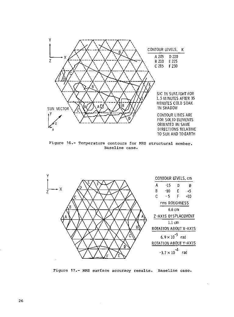
a significant design consideration. Selected thermal contours for dish members
oriented in the same direction are shown in figure 16. The solid lines denote the
structural members for which the temperature contours are applicable. Similar con-
tours are also plotted for both concave and convex surface members oriented in the
other directions. The contours aid the analyst in rapidly visualizing approximate
temperature ranges and distributions for the entire structure and is preferable in
the interactive analysis to review of temperature printouts for hundreds of members.
Surface Accuracy
Contours of the MRS surface distortions of the structural nodes on the mesh side
of the dish are shown in figure 17. The deviation from a perfect spherical segment
are caused principally by the structural loadings from the tension cables. MRS sur-
face roughness of 6.6 cm exceeds the 6-mm accuracy requirements by an order of magni-
tude. However, these distortions are principally affected by the cable tensioning
(note the near symmetry of contour patterns about the X- and Z-axes). Thus, it is
expected that predesign of the surface (i.e., tailored mesh offsets) to yield a
spherical mesh surface which, when under tension, will reduce the effective large-
scale distortion error to acceptable millimeter levels.
Defocus and boresight offset data for the dish are also presented in figure 17.
The surface is drawn inward (toward the feed) an average of 1.1 cm. More signifi-
cant, the tension cables draw the feed toward the dish by 22 cm for an overall
defocus distance of 23 cm. The boresight offset between the dish and feed is about
25 cm. This translates into a ground-track pointing-location error for the dish of
about 300 m which is within the 1-km resolution accuracy band. Proper predesign of
12

the preloaded antenna structural members should significantly reduce the defocus and
boresight errors for the MRS spacecraft.
If the tension cables are eliminated, the structural surface distortions caused
by environmental effects (thermal, gravity gradient, and atmospheric drag) are
reduced more than an order of magnitude and meet the 6-mm surface accuracy require-
ments as shown in figure 18. Defocus and boresight errors are reduced
commensurately.
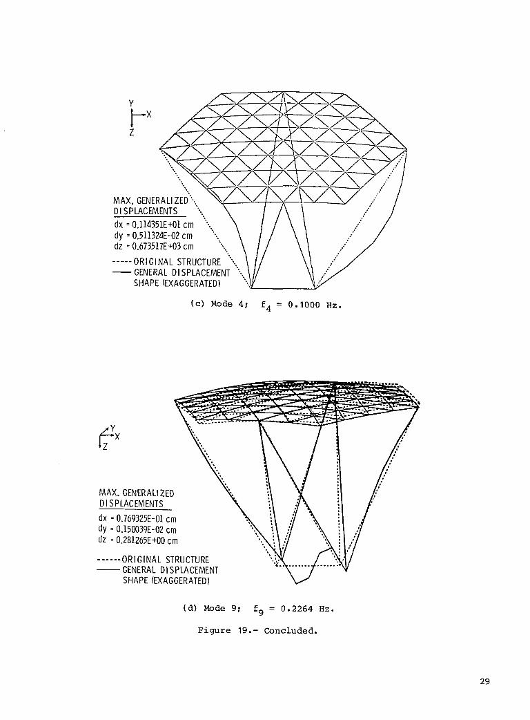
Dynamic Analysis
The lowest natural vibration frequencies for each of three MRS spacecraft sizes
range from 0.04 to 0.09 Hz and are listed in table VI. These frequencies are far
below the design capabilities of space-qualified controllers/actuators and will
require innovative control concepts and much more detailed analysis. Also shown is
the fundamental frequency of a 725-m-diameter dish which is an order of magnitude
higher than the spacecraft with the attached feed system. Selected mode shapes for
the MRS baseline are shown in figure 19. These figures were generated in the Inter-
active Plotting module from SAP dynamic solutions. Although this study did not
address minimum vibrational frequency or flexible-body control system requirements for
the MRS, it should be noted that the triangular truss beams could be replaced with
somewhat stiffer structural elements to provide moderate increases (possibly a factor
of 2 or 3) in the lower order frequencies. However, even with technology advances in
stiff, lightweight materials and structural design concepts, it is likely that these
low frequencies and possibly high-amplitude vibrations will be typical of large
future systems.
CONCLUDING REMARKS
Capabilities, performance, and advantages of a systems-oriented interactive
computer-aided design and analysis system have been presented. A single user at an
interactive terminal can create, design, analyze, and conduct parametric studies of
Earth-orbiting spacecraft with relative ease. The approach is shown to be particu-
larly useful in the conceptual design phase where various missions and spacecraft
options are to be evaluated in a cost-effective, timely manner.
The Large Advanced Space Systems (LASS) computer-aided design and analysis pro-
gram was developed specifically to provide spacecraft system analysts with the inter-
active capabilities to rapidly analyze and evaluate spacecraft performance across
several disciplines. The primary technical emphases are on structures, thermal ana-
lyses, and controls. Simple and efficient executive, data-base, and file management
systems relieve the analyst of much of the tedium associated with computer system
command protocol and formatted data inputs, reduce possibilities for input errors,
and greatly increase throughput capabilities. Extensive graphical displays let the
analyst rapidly evaluate the results, make timely design changes, and continue in the
interactive processing mode.
An example problem of a large microwave radiometer spacecraft in low-Earth orbit
has been used to illustrate current capabilities of the interactive LASS program.
Output results of the MRS study include optimized spacecraft mass, establishment of
propulsion and control system sensitivities to current and advanced subsystems,
13

optimized structural design, quantification of spacecraft loads and environmental
effects on antenna performance (surface accuracy), and definiton of structural
dynamics.
The interactive design and analysis capabilities for advanced spacecraft systems
are by no means complete; however, the LASS program represents a substantial start in
that direction. The program demonstrates that rapid modeling, analysis, and design of
integrated spacecraft can be accomplished with user interactive computer-aided design
software. Spacecraft redesign is easily accomplished and baseline designs can be
altered in an orderly manner for subsystem and mission design trades. Top-level
systems data are available to discipline analysts for subsystem reexamination and/or
refinement and for more rigorous analysis.
Langley Research Center
National Aeronautics and Space Administration
Hampton, VA 23665
November 12, 1981
REFERENCES
I. Leondis, Alex: Large Advanced Space Systems Computer-Aided Design and Analysis
Program. NASA CR-159191, 1980.
2. Wilhite, A. W.; and Rehder, J. J.: AVID: A Design System for Technology Studies
of Advanced Transportation Concepts. AIAA Paper 79-0872, May 1979.
3. Leondis, A. F.: Large Advanced Space System (LASS) Computer Program. AIAA
Paper 79-0904, May 1979.
4. Chiarappa, Daniel; and Eggleston, David: Low Altitude Vertistat Equations of
Motion. GDC-ERR-AN-977, General Dynamics/Convair Div., Dec. 1966.
5. Cook, G. E.: Satellite Drag Coefficients. Tech. Rep. 65005, British R.A.E.,
Jan. 1965. (Available from DTIC as AD 464 391.)
6. COSPAR Working Group IV, compilers: CIRA 1965. North-Holland Pub. Co.
(Amsterdam), 1965.
7. Cronk, M. J.: SOLID SAP: User's Manual. CASD-CIH-74-008, General Dynamics/
Convair Div., Oct. 1977. (Revised Oct. 1978.)
8. Ballinger, John C.; and Christensen, Emmet H.: Environmental Control Study of
Space Vehicles. (Part II) Thermal Environmental of Space - Supplement A:
Graphical Presentation of Solar, Planetary Thermal and Planetary Albedo Radia-
tion Incident to Space Vehicles. ERR-AN-016, Eng. Dep., General
Dynamics/Convair Div., Jan. 1961.
9. Comm. on Remote Sensing Programs for Earth Resource Surveys: Microwave Remote
Sensing From Space for Earth Resource Surveys. Contract NASW-3043, Natl. Acad.
Sci.-Natl. Res. Counc., 1977. (Available as NASA CR-15781.)
10. Lovelace, U. M.: A Microwave Radiometer Spacecraft. AAS 78-151, American Astro-
naut. Soc., Oct.-Nov. 1978.
14

TABLE I.- LASS MENU
[Input letter(s) of program(s) to be executed]
A - AVID DATA MANACEMENT_AM o AVID DMP
B - LASS PREPROCESSOR- ANALOG
C - TEIRAHEDRAL TG'4SS STRUCTURESYNTHESIZER - TTSS
r) - GI[NERAL TRUSS SYNTHESIZER - GTS
£ RIGID-BODY CONTROLDYNAMICS - RED
F THERMALANALYSIS - TA
C - STATIC LOADS - SL
H - STRUCTURALANALYSIS _AM ISTATIC _]YNAM]C_ - SAP
! SLt_FACEACCURACY-SA
J - ACTIVE DAMPING - ACTD
K - DYNAMIC LOADS - DL
L - LASS POST PROCESSOR- POST
M - LASS COST _AM - COST
N - EXIT LASS PROCi%AM
0 - BATCH TTSS
P - BATCH RED
0 - SYSTEMOESIC_ _ COST MODULE- SOCM
R - BATCHGTS
S - C,ENERAL TRUSS SYNTHESIZER (NON-DISH)
T - BATCH TA
U - INTERACTIVE MODEPLOTTING MODULE
v - BCX RING AND POST PROCESSOR
TABLE II.- LASS INPUT VARIABLES
! RFOM -RADIO FR£OLi(NCY DIAMETER IMETERS}2 SHAPE -SHAPE FLAG I-PARABOLA. ?-SPHERE, 3-FLAT3 FOVERD -FOCAL LENGTH TO RF DIAMETER RATIO4 NBA¥S -NUMBER OF BAYS IN REAl.. 0IS,H STRUCTURE5 A_AYS -ANALYSIS NIJINBEROF BAYS6 THETA -DIACONAL ANGLE TO SURFACE (RADIANS|7 500M -MESH STANO-OFF DISTANCE (METERS}8 M{XJNTF-DISH MOUNTING FLAG: B-APEX, 1-£OG£, 3-FRIEEg REMOVF-STRUT REMOVEFLAG: e-NO, D-NEWSET, g-REPEAT
10 NI_OOE -NI.JIHBEROF _ SPa_PES[e-NO SAP MOOELS)II XANACM-X COOROINATEFOR ANGULARACCELERATION [METERSI12 YANACM-Y COOROINATEFOR ANCAJLARACCELERATION |METERSI13 ZANACM-Z COORI_INATEFOR ANr_XJLARACCELERATION IMETERS)14 TUBTYP -STRUT TYPE (_-(./R, I-CUtER, 2o|SOG, 3-TRUSSIS SLOR -SURFACE STRUT L£N(:;TH OVER RADIUS Oi: GYR RATIO10 S00] -SURFACE STRUT DIAMETER OVER THICKNESS RATIO17 SSYMM -SURFACE STRUT YOUNCSMODULUS(NEWTONS/SQUAREMETER|18 SMINC_ -SURFACE STRUT MINII'_ DIAMETER (METERS]10 SMINTM -SURFACE STRUT MINII_JM THICKNESS [METERS2_ SPCRI'I -SURFACE STRUT EULER LOAD FOR I:IESIGN INEWTONS)21 SHAR -SURFACE STRUT HINGE AREA RATIO22 SHLR -SURFACE STRUT HINGE LENGTH RATIO23 SFb"W_O-SURFACE STRUT HINF._ MOOULUSOR TRUSS LACE PIOOLILUS24 OLOR -DIACONAL STRUT LENOTH OVER RADIUS OF GYR RATIO25 DDOT -DIACONAL STRUT DIAMETER OVER THICKNESS RATIO21_ DSYMM -DIAGONAL STRUT YOLIMGSMCIDULUSINEWTOI%'S/S{:_JAREMETER}27 OMINDH -DIAGONAL STRUT MINII"_ DIAf'IETER (METERS}28 DI'I]NTM -DIAGONAL STRUT MINIHUN THICKNESS IHE'I'ERS)2g DPCRM -DIA_L STRUT EULER LOAD FOR I:}IESIGN {NEWTONS}3_ DIFRO0 -DIACONAL STRUT PIN-ENDED (ROD] FLAG: _-BEAM, I-RO{]31 DSSM -DIAGONAL STRUT SHEAR MODULUSIN/MIX2} USED IF DIFROO-e.32 SRH0 -SURFACE STRUT DENSITY {_]LOCRAMS/CUBIC /_ETERI33 SSBRW -SURFACE STRUT BEARING REFERENCEWEIr._-IT (KIL0f.A_AMSI34 SEFRW -SURFACE STRUT END FITTING REFERENCE WEIC_T (KIL0r__RAMS)35 5HLAEE -SURFACE STRUT HINGE OR LACE DENSITY (KILOGRAMS/M£TERII3I
DRFIOM -DIAGONAL STRUT DENSITY {KILOC__qAMS/CLIBICMETER)37 [_58Rw -DIAGONAL STRUT BEARING REFERENCE wEIGHT IKILOGRAMS}38 DEFRW -DIAGONAL STRUT END FITTING REFERENCE WEIGHT (KILOr_..,RAMSI3g DLACE -DIAGONAL STRUT TRUSS LACING DENSITY (KILOCRAMS/METERII3I4e UWSTON-UNIT WEIGHT OF STAND-OFF I I IWIETERSLONG) [KILOC.RAHS)41 SRWI'I -SPIDER REFERENCE WEIGHT {KILOCRAMS|42 LA#MESH-UNIT WEIGHT OF MESH (KILOC,RAMSISQUARE METER|"13 U_MCSR-MESH SYSTEM 'TOMESH DNLY 'WEIGHTRATID44 WTCONT -WEIGHT CONTINGENCY {ALL WEIGHTI{I*WTCONTI)45 MESH(_IK-MESH ON 8AC_ FLAG (-1 , ONLY IF FLATI O-FRONT
15

TABLE III.- RIGID-BODY CONTROL DYNAMICS INPUT
I H - ORBIT ALTITUDE (METERS)2 INCLIN -ORBIT INCLINATION IRADIANS)
3 PSIN -.ORBIT ASCENDING NODE (RADIANS4 TFUEL - TIME BETWEEN REFUELling .",:EARS,5 ISP - SPECIFIC IMPULSE (HEWTON-SECONDS PER KILOGRAMJ6 CD - AERODYNAMIC DRAG COEFFICIENT
7 IE - ORIENTATION FLAG (= I. FO_ INERTIAL OR = 2. FOR EARTH)B OPSI -EULER ANGLES (3) DEFINING ORIENTATION OF SPACECRAFT FOR BSTH9 OTHETA INERTIAL AND EARTH. OPSI IS ROTATION ABOUT THE Z AXIS,
10 OPHI OTHETA ABOUT THE NEW Y AXIS. OPHI ABOUT >c. (RADIANS)
11 WM3(1 ) - SPACECRAFT MANEUVER RATE REQUIREMENT X, Y, Z COMPONENTS12 WM3(2) RESPECTIVELY (RADIANS PER SECOND%13 idM3"(3)
14 ALFAM3 - SPACECRAFT M;_4EUVER ACCELERATION REGUIREMENT X, Y. Z
15 (2) COMPONENTS RESPECTIVELY (RADIANS PER SECOND SQUARED)16 (3}
17 NM - NUMBER OF MANEUVERS PER ORBIT
IB E3(1) - INERTIAL ATTITUDE ACCURACY REQUIREMENT X, Y, Z COMPONENTS19 E3(2) RESPECTIVELY (RADIANS)20 E3(3)
21 UAS3(1 }- UNIT VECTOR ALONG AMCD SPIN AXIS X, Y, Z COMPONENTS22 UAS3 (2) RESPECTIVELY_3 UAS3 (3)
_4 _AMMA - _CD IoIVDT AXIS ANGULAR-RANGE IRADIANS)_S _0 -_-AMCD L_41T WHEEL RADIUS (METERS)
_S _-MA - _ATIO OF TOTAL TO DOUBLE WHEEL MASS27 K_J - AMCD MASS SIZING PROPORTIONALITY FACTOR (METERS PER SECOND)2B t4ORDES - NUMBER OF ORBITS BETWEEN DESATURATIONS29 _CS - MASS OF ACS EXCLUDIHG AMCD ACTUATION ASSEMBLY (KILOGRAMS)30 PACS - POWER REQUIREMENT OF ACS EXCLUDING AMCD SPIN AXIS (WATTS)
31 LMII} - MINIML_I LINEAR IMPULSE BIT WHEN CONTROLLING TORQUE,32 LM(2) X, Y, Z AXES RESPECTIVELY {NEWTON-SECONDS)33 LM (3)
34 NRCSGP - NUMBER OF THRUSTER GRIDPOINTS (= NL_IBER OF RE_dS IN RCSMAT)
TABLE IV.- MRS SYSTEM DESIGN REQUIREMENTS
Frequency, GHz ................................................ 1.08, 2.03, and 4.95
Resolution, km .................................................................. I
aperture, m/beam ............................................. 300 (nominal)
antenna aperture, m ............................................ 750 (nominal)
length, m ...................................................... 575 (nominal)
........................................................................ 70
accuracy, mm ...................................................... . ..... 6
altitude range, km ............................................... 400 to 1000
orbit altitude, km ..................................................... 750
inclination .......................................... 60 ° and Sun synchronous
Lifetime, yr .................................................... 15 with 3 resupply
accuracy, deg ....................................................... 0.01
rate, deg/sec ........................................................... 0.060
rate, bps ........................................................... _30 x 106
kW ....................................................................... 10
system ........................................ Shuttle transportation system

TABLE V.- MEMBER TEMPERATURES
Maximum/minimum temperature, K, for -
Point
Concave surface Convex Diagonal Feed Feed support Tension(mesh side) surface beam beam cables
A 312/232 312/237 312/236 313 312/308 310/286
B 191/183 184/183 179/176 191 179/179 180/180
C 251/201 264/196 255/214 267 261/256 262/229
D 332/324 328/324 325/300 321 298/271 301/275
TABLE VI.- LASS DYNAMIC ANALYSIS FOR
FIRST NATURAL VIBRATIONAL FREQUENCY
MRS antenna First elastic
diameter, m frequency, Hz
400 0.09019
750 .0560
1000 .04191
Dish only .6255
(725 diam.)
17

AV'OEXECUi'VES S MlAVID DATA AVIDMGMT PROG DATA BASE
I TETRAHEDRALTRUSS I
l STRUCTURE ,IGENERALTRUSS|r ELEM I SYNTHESIZER _ ANALOG I SYNTHESIZER I-E_EM--I
'D__E_GN; _ ' ,L L DESIGN j
I PROPITANKMASSES RIGID-BODY lI AMCDMASSES CONTROLDYNAMICSI CG. CP. INERTIAS
I RCSTORQUES . 1
LITHERMAL ANALYSIS I STATICLOADSJ_-"ISAP (STATIC)I ISAP (DYNAMIC)__
l PRETENSION I _ IELEMFORCES] MODES -7I THERMAL I _ CONTINUE! DEFLECT ! FREQUENCY I"I bKAV UffAU I I /FI FM_ + ISTRESSES ', GENDEFLECTiIATMOS DRAG, I_'pr6F_ih_i',,---I--" "
ISTATICTHRUSTI I X_L_ 7 NO '[IDYNAM,CIi _ RETURNTO I LOADS/I
[ D_T6_YI-6"N-S-ISURFACEACCURACYI _SS ORGTS I ACTIVEIIDAMPINGI,BORESIGHTCHANGESi [ ELASTICDEFLECT'IJ
IPOSTPROCESSOR I IGYRO DAMPER SIZE,I
I_ ; ELEMLOADS l_I DDT&E ........
l FIRST UNIT _'-----_ _EM, _.,[ _ RETURNTO YES
TTSSORGTS" _uL_,_CONTINUE _ NO "X_/
Figure I.- LASS computer program flowchart.
IN OUT IN OUT
LASSD8 I JLASSOB ANALOG MOOLAN STAMOO SAP STAPEg$1mTlC
1 IDYNMOO LASSOB 1MDDLAN TTSS OESIGN GTMX STLO 2 LASSDB
CT.x GTS GTMX OYML SA OIAPEgI TSSOP AREAGP ¥N&MIC
_^_0B I IDY"L RCD DYML SA LASSDBAREACP STAPEg
AREAGP
RCSMAT* j LASSOB IDTAPEg
I LASSDB I I LASSDBLASSOB TA DYFFMX DYLO/AD CT.xDYML TATMPS AMCDMX DYFFMX
STTHHX
LASSDe I LASSDB GTMX J
CTMxOYML J STAMOD LASSOB ISTLO 1 TTSSOPAREAGP AMCDMX POST
TAIMPS STTHMX
AMCDMX [STTHMXLASSDB LASSDB
LCERDB COST LCERDB
I* BATCH EXIT
Figure 2.- File structure of LASS,
18

_._.._'CARPENTER" LEAF SPRING
HINGEDSTRUCTURALMEMBER
_ J@ DA L._.J
PACKAGETYPE B _NGE-i,
34 FULLYDEPLOYED
65 76 , [ .8 _IAGONAL
8 BAYS 10 BAYS _'=;" ANGLEBAY DEFINITIONS
(a) Configuration definition.
i 2 3
HOLLOWTUBE I SOGRID TRIANGULARTRUSS
(b) Structural member types.
Figure 3.- Principal features in TTSS module.
19

IEAL ANA GY
32 _' 4 BAYS_6864STRUCTURALELEMENTS t02 STRUCTURALELEMENTS1585NODES 3]. NODES
Figure 4.- Analogous modeling concept.
SLEWREQTL_ MOMENTUM
EXCHANGESYSTEM ----_PREDESIGNDATASIZING
CYCLICMOMENTUM I IMOMENTUM lCALCULATE DESATURATION PROPULSIONI
ENVIRONMENTJ ORBIT ORBIT/STATIONKEEPING_ SYSTEM
TORQUEANDFORCE[-'1 ENVIRONMENTANALYSIS ]REQUIREMENTS
INPUT- ATMOSDRAG __ REACTIONTHRUSTERSONLYACSGRAVGRAD
OTHER
Figure 5.- Rigid-body control dynamics module.
20

I i / iI _I / /
_ I I I i
l I l I I
_/_ HORN
J-RECEIVER
____ ,_ _ FOCALARC _:_ X X )_:_MICROWAVE I__,DIATION
,_ "_ATA RELAY
SWATH
r--_RESOLUTION BRIGHTNESS --
' ELEMENT TEMPERATURE
I I I I I I ISWATH
Figure 6.- Microwave sensing concept.
PROPELLANTTANKS(3)_ SOLARPANELS-_x,x,x,x,x,x,x,x,x_cl I.._FGYRO DAMPERS
, - -- (21
, RcsTHRUSTERS\ / --. _" AMRn / "-SERVICE MODULES
_%"_ _.. _'io";,';'_,;_,/ (21ORAP_ //\ __EL.v__"" "'""7COMPOSITETETRAHEDRAL// \/ L92EN /TRUSSSTRUCTURE II \_ UAULI-b /
(HOLLOWRO_EMENTS} // II /
__---- GRAPHITE/EPOXY _-GRAPHITE/EPO×Y COMPOSITECOMPOSITE FEED\\ FEEDSUPPORTBEAM
\\ ARRAY BEAM ffRIANGULARSTRUTS (21)...... \\ffRIANGULAR STRUT1
ORBIT KEEPING \_ _/_ /-SENSOR MODULETHRUSTERS(4) _ ,, •
!RS (4)--_\ _-_ NOTE: ALUMINIZED KAPTONANTENNAMESH NOT SHOWN
Figure 7.- Microwave radiation spacecraft.
21

_--_ WHEEL/RING
CONTROLRACE,._j
RINGS-------// _ SENSOR
Figure 8.- Dual-momentum vector control concept.
103200 X
,(\ \ BASELINE /_T TALSICMRS ' 0
150 . \ I / . MASS
CUMULATIVE I _,MASS, 100 _\ STRUCTUREkg \\\\(ELEMENTS,CONNECTORS,
\_ HINGES,ETC.)
PROPELLANT _. 1
soIsp=400sec) _I _MESH
AMCD/
0200 400 600 800 i000
ANTENNADIAMETER.mALTITUDE.km
Figure 9.- MRS mass optimization.
22

200-x 103 I \/-CRYOGENIC PROPELLANT
,,,150-
TOTALSPACECRAFT _ "x_j/_
MASS. kg
x _ PROPULSION_
(Isp= 3000sec)500 i i i i i
200 400 600 800 i000
ANTENNADIAMETER,mALTITUDE,km
Figure I0.- Cryogenic versus electric propulsion options.
100000 -
,%'%.\%%
xk. ". /- PROP_%_ToMNN_SSNFoORRcCS,
MASS,kgl0000 _ AMCDANDPROPULSION
PROPELLANT-__
AMCD/ ""
I000 ........ ' ........ ii00 I000 i0 000
SPECIFICIMPULSE.sec
Figure 11.- MRS control subsystems trade-off.
750-m diameter; 750-km altitude; 3-yr
propellant resupply.
23

NOBtOCKAOEI_-:___q)A3B3_COMPLE_BLOCKAOE
PARTIALBLOCKAGE _']
AN
°___. Vm-_A__O_CU_SP_OVo= SICVELOCITYIN ORBIT
EACHNODEPOINTREDUCEDTOEQUIVALENTCIRCULARAREAEACHAREAHAS A BLOCKAGEFACTOR,B (= 1 IF SOLID)MASKINGAREASREDUCEDIN PROPORTIONTO DOWNSTREAMDISTANCEDRAGIS FUNCTIONOFMASKEDAREATIMES BLOCKAGEFACTOR
Figure 12.- Atmospheric drag approximation.
240-
CONCAVESURFACE _ _ DIAGONAL
_u_ o_o _ _ _MEMBERS _ _
o I_nHn_ _ _MEMBERLOADS,newtons
160-CONVEXSURFACE
120_
NUMBEROF MEMBERSMEMBERS 80 + TENSION
-- COMPRESSION40
0 .... _ ,_. _. ,-e ,..e
MEMBERLOADS,newtons
Figure 13.- MRS member loads for five-load condition (atmospheric drag,
gravity gradient, static thrust, thermal, and pretensioning).
24

CONVEXSURFACE DIAGONAL
400 MEMBERS 320 MEMBERS
_oo _ _o _ _"-_ //s + TENSIONY'/: _ "'" -COMPRESSION
NUMBEROF 200 "'" 160MEMBERS 72
1oo _ _ _o
-625-375-125 125 375 025-62 -375-125 125 375 625
MEMBERLOADS, newtons
Figure 14.- MRS member loads for three environmental loads
(thermal, gravity gradient, and atmospheric drag).
+ TENSION- COMPRESSION
CONVEXSURFACE400 - MEMBERS 320 DIAGONAL
_ MEMBERS300 - 240 ,_
NUMBEROF _ _ _
_s _oo,- _ _ _o100 - _ 80
o _ _ ,o _ , ,-625 -375 -125 125 375 625 -625 -375 -125 125 375 625
MEMBERLOADS, newtons
Figure 15.- MRS member loads for thermal load only.
25
i ........-----_-_7"'---'#k,,--_u,-.,, CONTOURLEVELS. K/ \"_\ / \ A 205 D 220
<i--/_-_k-7\ , B210 E225\,, C 215 F230
--7c,.... TC---_-- 7,,_.._,,,/',,/,,,
% .......
1.5 MINUTES AFTER35MINUTESCOLDSOAK
SUN VECTOR"\/C\_'k_ZJ' _'T IN SHADOW
• Y _--_ CONTOURLINESARE
_z \_I;',L:I',Y _o=so_,o_=_sORIENTEDIN SAMEx DIRECTIONSRELATIVE
TO SUNAND TOEARTH
Figure 16.- Temperature contours for MRS structural member.Baseline case.
Y CONTOURLEVELS.cm
[_ A -15 D 0Z B -I0 E +5
C - 5 F +I0
rms ROUGHNESS
6.6cm
Z-AXIS DISPLACEMENT
I.I cm
ROTATIONABOUTX-AXIS
6.9x10 .5 rad
ROTATIONABOUTY-AXIS
-3.7 x 10.4 rad
Figure 17.- MRS surface accuracy results. Baseline case.
26

Y CONTROLLEVELS,cm
Z_ A -.050 D +.025X B -.025 E +.050
C 0 F + .075G +.i00
_X rmsROUGHNESS
3.5x lO-2cm, Z_AX_'I_S'_D_ME NT
2.2 x 10⁻²cm
ROTATIONABOUTX-AXIS
F -7.5 x i0-7 radROTATIONABOUTY-AXIS
-i. 3 x 10.6 rad
Figure 18.- MRS distortions from environmental loads.
27

MAX. GENERALIZEDDISPLACEMENTS
d× : 0.6zII500E-02cmdy =0.186487E-03cmdz =0.332419E+00cm
.... ORIGINALSTRUCTUREGENERALDISPLACEMENTSHAPE(EXAGGERATED)
(a) Mode I; fl = 0.05601Hz.
Y
MAX. GENERALIZEDDISPLACEMENTS
dx =0.227811E-03cmdy =0.277zI22E+00cmdz =0.I14786E+00cm
..... ORIGINALSTRUCTUREGENERALDISPLACEMENTSHAPE(EXAGGERATED)
(b) Mode 2; f2 = 0.06935 Hz.
Figure 19.- Generalized displacements from LASS dynamic
analysis for MRS baseline case.
28
--XZ
MAX. GENERALIZED'..
DISPLACEMENTS '-. \"... \
dy =0.511324E-02cm ".,,, \dz =0.6735].7E+03cm ",,,. \
..... ORIGINAL STRUCTURE ",. \
-- GENERALD,SPLACEMENT-'-../_/SHAPE(EXAGGERATED) ;V /
(c) Mode 4; f4 = 0.1000 Hz.
N_AX.GENERALIZEDDISPLACEMENTS
dx : 0 769325E-01cmdy : 0 15003gE-02cmdz =0 281265E+00cm
4
...... ORIGINALSTRUCTURE "'GENERALDISPLACEMENTSHAPE(EXAGGERATED)
(d) Mode 9; f9 = 0.2264 Hz.
Figure 19.- Concluded.
29


1. Report NO. 2. Government Accession No. 3. Recipient's _1_ No.
NASA TP-1937
4. Titleand Subtitle 5. Repo_ Date
INTERACTIVE DESIGN AND ANALYSIS OF FUTURE LARGE December 1981
SPACECRAFT CONCEPTS 6. Performing Or_nizationCode
506-62-43-07
7. Author(s) 8. PerformingOr_nlzation Report No.
L. Bernard Garrett L-14739
,. 10. Work Unit No.
9. Performing Organization Name and Addre_
NASA Langley Research Center "'11. Contract or Grant'No.
Hampton, VA 23665
13. Ty_ of Repo_ and Period Cover_
12. Sponsoring Agency Name and Address Technical Paper
National Aeronautics and Space Administration 14. Sponsoring Agency CodeWashington, DC 20546
15. _pplementary Notes
This report was presented at the AIAA 16th Thermophysics Conference at Palo Alto,California, June 23-25, 1981, and is available as AIAA Paper No. 81-1177.
16. Abstract
An overview is presented of an interactive computer-aided design program used to
perform systems-level design and analysis of large spacecraft concepts. The primary
emphases are on rapid design and analysis of integrated spacecraft, including
automatic spacecraft modeling for lattice (trusslike) structures. Capabilities and
performance of the twenty-some multidiscipline applications modules, the executive
and data management software, and graphics display features are reviewed. A single
user at an interactive terminal can create, design, analyze, and conduct parametric
studies of Earth-orbiting spacecraft with relative ease. The approach is
particularly useful in the conceptual design phase of advanced space missions when a
multiplicity of concepts must be evaluated in a cost-effective and timely manner.
Data generated in the design, analysis, and performance evaluation of an Earth-
orbiting large-diameter (750-m) antenna satellite are used to illustrate current
capabilities. Computer run time statistics for the individual modules quantify the
speed at which modeling, analysis, and design evaluation of integrated spacecraft
concepts can be accomplished in a user interactive computing environment.
17. Key Words (Suggested by Author(s)) 18. Distribution Statement
Interactive computer-aided design Unclassified- Unlimited
Large space systems
Spacecraft design
Subject Category 18
19. Security Classif.(of this report) 20. Security Classif. (of this page) 21. No. of Pages 22. Price
Unclassified Unclassified 32 A03
For sale by theNationalTechnicalInformationService,Springfield,Virginia 22161lIASA-tangley,]9GI


%_ ,9 _ _* . - _ LANGLEY RESEARCH CENTER
/ll!l/////l///l///l////l///l///ll/////l/l////l////l/l////l/////INational Aeronautics and THIRD-CLASS BULK RATE Postage ahd
Space Administration NationalAei 3 1176 00519 4734Space Administrat_n
Washington, D.C. NASA-45120546
Official Business
Penalty for Private Use, $300
__A POSTMASTER: If Undeliverable (Section 158Postal Manual) Do Not Return
Related Documents


![[@IndeedEng] Large scale interactive analytics with Imhotep](https://static.cupdf.com/doc/110x72/548497a45806b5cc588b4649/indeedeng-large-scale-interactive-analytics-with-imhotep.jpg)