Notes III Notes ■ Delivery and s tor age Packing box over 6 layers in pile is unallowed. Never climb the packing box, neither stand on it, nor place heavy objects on it. Do no t mov e or drag the product by the cab les connected with it. Forbid collision or scratch to the panel and displayer. Packing box should be protected from damping, insolation and raining. ■ Open packing box to check Ensure things in packing box are the required ones. Ensure the product is not damaged in delivery. Ensure the parts i n pa cking box a re in accordance to th e ord er. Contact us in time if the product ty pe is in consistent with the order, the re is s hort of accessories, or product damage in delivery. ■ Connection Only qualified persons can connect the system or check the connection. The sy stem must be earthed, its r esistance must be less tha n 4 Ω and the ground wire cannot be replaced by zero wire. Connection must be correct and fir m to avoid t he pr oduct to be da maged or other unexpected result. Connect w ith surge diode in the specified direction to avoid the damage to the syste m. Switch o ff power supply before p ulling o ut plug or open ing electr ic cabinet. ■ Troubleshootin g Switch off power supply before troubleshoo ting or changing components. Troublesho ot and then sta rtup th e system when th ere is short cir cuit or overloa d. Do not switch on or off it freque ntly and an interv al is 1 minute at least after the system is powered on again.

Welcome message from author
This document is posted to help you gain knowledge. Please leave a comment to let me know what you think about it! Share it to your friends and learn new things together.
Transcript
8/17/2019 980TDc CNC Turning Controller User Manual
http://slidepdf.com/reader/full/980tdc-cnc-turning-controller-user-manual 1/461
Notes
III
Notes
Delivery and storage
Packing box over 6 layers in pile is unallowed.
Never climb the packing box, neither stand on it, nor place heavy objects on it.
Do not move or drag the product by the cables connected with it.
Forbid collision or scratch to the panel and displayer.
Packing box should be protected from damping, insolation and raining.
Open packing box to check
Ensure things in packing box are the required ones.
Ensure the product is not damaged in delivery.
Ensure the parts in packing box are in accordance to the order.
Contact us in time if the product type is inconsistent with the order, there is short of
accessories, or product damage in delivery.
Connection
Only qualified persons can connect the system or check the connection.
The system must be earthed, its resistance must be less than 4Ω and the ground wire
cannot be replaced by zero wire.
Connection must be correct and firm to avoid the product to be damaged or other
unexpected result.
Connect with surge diode in the specified direction to avoid the damage to the system.
Switch off power supply before pulling out plug or opening electric cabinet.
Troubleshooting
Switch off power supply before troubleshooting or changing components.
Troubleshoot and then startup the system when there is short circuit or overload.
Do not switch on or off it frequently and an interval is 1 minute at least after the system is
powered on again.

8/17/2019 980TDc CNC Turning Controller User Manual
http://slidepdf.com/reader/full/980tdc-cnc-turning-controller-user-manual 2/461
GSK980TDc Turning CNC System User Manual
IV
All specification and designs are subject to change without further notice.
Warning!
Please read this user manual and a manual from machine builder completelybefore installation, programming and operation; do operate the system and
machine according to user manuals, otherwise it may damage the system,
machine, workpiece and even injure the operator.
Cautions!
Functions, technical indexes described in this user manual are only for the
system. Actual functions and technical performance of machine tool with this
CNC system are determined by machine builder’s design, so refer to its user
manual.
The system is employed with integrated machine control panel and the keys
on machine control panel are defined by PLC program. Functions of keys in
this user manual are for standard PLC program. Please notice it!
Refer to user manual from machine manufacturer about functions and
meanings of keys on machine control panel.
Announcement!
This manual describes various items as much as possible. However,
operations allowable or unallowable can not be explained one by one due to
so many possibilities that may involve with, so the contents that are not
specially stated in this manual shall be considered to be unavailable.

8/17/2019 980TDc CNC Turning Controller User Manual
http://slidepdf.com/reader/full/980tdc-cnc-turning-controller-user-manual 3/461
Summary
V
Programming
GSK980TDc CNC Technical Specification, Product
Type, Command and Program Format
Operation
GSK980TDc CNC Operation Use
Ⅲ Installation and Connection
GSK980TDc CNC Installation, Connection and Setting
Appendix
CNC Ladder Function Allocation, Alarm Message Table

8/17/2019 980TDc CNC Turning Controller User Manual
http://slidepdf.com/reader/full/980tdc-cnc-turning-controller-user-manual 4/461
GSK980TDc Turning CNC System User Manual
VI
Safety Responsibility
Manufacturer’s safety responsibility
—— The manufacturer should be responsible for the cleared or the controlled safety in the design
and the structure of the CNC system and the accessories.
——The manufacturer should be responsible for the CNC system and the accessories.
——The manufacturer should be responsible for the message and the suggestion for the user.
User’s safety responsibility
—— The user should study and train the system safety operation, master the safety operation
content.
—— The user should be responsible for the danger caused by increasing, changing or modifying
the CNC system, the accessories by itself.
—— The user should be responsible for the danger because of the mistaken operation, regulation,
maintenance, installation and storage.

8/17/2019 980TDc CNC Turning Controller User Manual
http://slidepdf.com/reader/full/980tdc-cnc-turning-controller-user-manual 5/461
Contents
I
CONTENTS
Programming
CHAPTER 1 PROGRAMMING .......................................................................................................... 1
1.1 GSK980TDc Introduction ....................................................................................................... 1
1.1.1 Product introduction ..................................................................................................... 1
1.1.2 Technical specification ................................................................................................. 2
1.1.3 Environment and conditions......................................................................................... 4
1.1.4 Power supply ................................................................................................................ 5
1.1.5 Guard ........................................................................................................................... 51.2 CNC System of Machine Tools and CNC Machine Tools ...................................................... 5
1.3 Programming Fundamentals .................................................................................................. 7
1.3.1 Coordinates definition .................................................................................................. 71.3.2 Machine coordinate system, Machine Zero and machine reference point .................. 7
1.3.3 Workpiece coordinate system and Program Zero ....................................................... 8
1.3.4 Interpolation function .................................................................................................... 9
1.3.5 Absolute programming and incremental programming ............................................. 10
1.3.6 Diameter programming and radius programming ...................................................... 101.4 Structure of an NC Program ................................................................................................. 11
1.4.1 General structure of a program .................................................................................. 11
1.4.2 Main program and subprogram ................................................................................. 151.5 Program Run ........................................................................................................................ 15
1.5.1 Sequence of program run .......................................................................................... 15
1.5.2 Execution sequence of word ...................................................................................... 161.6 Basic Axis Incremental System ............................................................................................ 17
1.6.1 Incremental system speed of basic axis .................................................................... 17
1.6.2 Incremental system unit of basic axis ........................................................................ 17
1.6.3 Incremental system data range of basic axis............................................................. 18
1.6.4 Incremental system data range and unit of basic axis............................................... 18
1.6.5 Program address value unit and range of incremental system of basic axis ............ 201.7 Additional Axis Incremental System ..................................................................................... 21
1.7.1 Additional axis being the current incremental system ............................................... 21
1.7.2 Additional axis being IS-A incremental system .......................................................... 21
CHAPTER 2 MSTF COMMAND ....................................................................................................... 22
2.1 M (Miscellaneous Function) ................................................................................................. 22
End of program M02 ........................................................................................................... 22
End of program run M30 ..................................................................................................... 22
Subprogram call M98 .......................................................................................................... 23
Return from subprogram M99 ............................................................................................. 23
Macro program call M9000~M9999................................................................................... 24
M commands defined by standard PLC ladder diagram ....................................................... 24
Program stop M00 ............................................................................................................... 25
Program optional stop M01.................................................................................................... 25
Spindle CW, CCW and stop control M03, M04, M05 ............................................................ 26Cooling control M08, M09 ................................................................................................... 26
Tailstock control M10, M11 .................................................................................................. 26
8/17/2019 980TDc CNC Turning Controller User Manual
http://slidepdf.com/reader/full/980tdc-cnc-turning-controller-user-manual 6/461
GSK980TDc Turning CNC System User Manual
II
Chuck control M12, M13 ..................................................................................................... 26
Spindle position/speed control switch M14, M15 .................................................................. 26
Spindle clamped/released M20, M21 .................................................................................... 27
The 2nd spindle position/speed switch M24, M25 ................................................................ 27
Lubricating control M32, M33 ................................................................................................ 27
Spindle automatic gear change M41, M42, M43, M44 .......................................................... 27Spindle 8-point orientation M50~M58 .................................................................................. 27
The 2nd spindle rotation CCW, rotation CW , stop M63, M64, M65 ..................................... 272.2 Spindle Function ................................................................................................................... 28
2.2.1 Spindle speed switching value control ....................................................................... 28
2.2.2 Spindle speed analog voltage control ........................................................................ 28
2.2.3 Constant surface speed control G96, constant rotational speed control G97 ........... 29
2.2.4 Spindle override ......................................................................................................... 31
2.2.5 Multiple spindle control function ................................................................................. 32
2.2.6 Cs contour control funciton ........................................................................................ 332.3 Tool Function ........................................................................................................................ 33
2.3.1 Tool control ................................................................................................................. 33
2.3.2 Tool life management ................................................................................................. 37
CHAPTER 3 G COMMANDS ........................................................................................................... 46
3.1 Commands ........................................................................................................................... 46
3.1.1 Modal, non-modal and initial mode ............................................................................ 47
3.1.2 Omitting words ........................................................................................................... 48
3.1.3 Related definitions...................................................................................................... 493.2 Rapid Traverse Movement G00 ......................................................................................... 49
3.3 Linear Interpolation G01 .................................................................................................... 50
3.4 Circular Interpolation G02, G03 ......................................................................................... 513.5 Three-point Circular Interpolation G05 .............................................................................. 54
3.6 Ellipse Interpolation G6.2, G6.3 ........................................................................................... 56
3.7 Parabola Interpolation G7.2, G7.3 ..................................................................................... 59
3.8 Plane Selection G17~G19 .................................................................................................. 61
3.9 Polar Coordinate Interpolation G12.1, G13.1....................................................................... 62
3.10 Cylindrical Interpolation G7.1 ............................................................................................. 65
3.11 Chamfering Function .......................................................................................................... 68
3.11.1 Linear chamfering ..................................................................................................... 68
3.11.2 Circular chamfering .................................................................................................. 70
3.11.3 Special cases ........................................................................................................... 723.12 Dwell G04 ........................................................................................................................ 74
3.13 Machine Zero Function....................................................................................................... 74
3.13.1 Machine 1st reference point G28 .......................................................................... 74
3.13.2 Machine 2nd, 3rd, 4th reference point G30 .......................................................... 753.14 Skip Interpolation G31 ..................................................................................................... 77
3.15 Automatic Tool Offset G36, G37 ...................................................................................... 79
3.16 Workpiece Coordinate System G50 ................................................................................ 81
3.17 Local Coordinate System ................................................................................................... 82
3.18 Workpiece Coordinate System G54~G59 ........................................................................ 84
3.19 Fixed Cycle Command ....................................................................................................... 873.19.1 Axial cutting cycle G90 .......................................................................................... 87
3.19.2 Radial cutting cycle G94........................................................................................ 90
8/17/2019 980TDc CNC Turning Controller User Manual
http://slidepdf.com/reader/full/980tdc-cnc-turning-controller-user-manual 7/461
Contents
III
3.19.3 Caution of fixed cycle commands ............................................................................ 923.20 Multiple Cycle Commands ................................................................................................. 93
3.20.1 Axial roughing cycle G71 ......................................................................................... 93
3.20.2 Radial roughing cycle G72 ....................................................................................... 99
3.20.3 Closed cutting cycle G73 ..................................................................................... 103
3.20.4 Finishing cycle G70 ................................................................................................ 1073.20.5 Axial grooving multiple cycle G74 ....................................................................... 108
3.20.6 Radial grooving multiple cycle G75 ....................................................................... 1113.21 Thread Cutting Commands .............................................................................................. 114
3.21.1 Thread cutting with constant lead G32 .................................................................. 115
3.21.2 Rigid thread cutting G32.1 ..................................................................................... 117
3.21.3 Thread cutting with variable lead G34................................................................. 119
3.21.4 Z thread cutting G33 ............................................................................................ 121
3.21.5 Rigid tapping G84, G88 ......................................................................................... 122
3.21.6 Thread cutting cycle G92 ....................................................................................... 125
3.21.7 Multiple thread cutting cycle G76 ........................................................................... 1283.22 Constant Surface Speed Control G96, Constant Rotational Speed Control G97 ...... 132
3.23 Feedrate per Minute G98, Feedrate per Rev G99 ........................................................... 133
3.24. Additional Axis Function .................................................................................................. 135
3.24.1 Additional axis start ................................................................................................ 135
3.24.2 Motion of additional axis ........................................................................................ 135
3.24.3 Additional axis coordinates display ........................................................................ 1353.25 Macro Commands ............................................................................................................ 135
3.25.1 MACRO variables .................................................................................................. 136
3.25.2 Operation and jump command G65 .................................................................... 140
3.25.3 Program example with macro command ............................................................... 143
3.26 Statement Macro Command............................................................................................. 146
3.26.1 Arithmetic and logic operation ............................................................................... 146
3.26.2 Transfer and cycle .................................................................................................. 1473.27 Metric/Inch Switch ............................................................................................................ 150
CHAPTER 4 TOOL NOSE RADIUS COMPENSATION (G41, G42) ............................................. 152
4.1 Application .......................................................................................................................... 152
4.1.1 Overview .................................................................................................................. 152
4.1.2 Imaginary tool nose direction ................................................................................... 152
4.1.3 Compensation value setting ..................................................................................... 156
4.1.4 Command format ..................................................................................................... 1574.1.5 Compensation direction ........................................................................................... 157
4.1.6 Notes ........................................................................................................................ 159
4.1.7 Application ................................................................................................................ 1604.2 Tool Nose Radius Compensation Offset Path .................................................................... 161
4.2.1 Inner and outer side ................................................................................................. 161
4.2.2 Tool traversing when starting tool ............................................................................ 162
4.2.3 Tool traversing in Offset mode ................................................................................. 163
4.2.4 Tool traversing in Offset canceling mode ................................................................. 167
4.2.5 Tool interference check ............................................................................................ 168
4.2.6 Commands for canceling compensation vector temporarily.................................... 170

8/17/2019 980TDc CNC Turning Controller User Manual
http://slidepdf.com/reader/full/980tdc-cnc-turning-controller-user-manual 8/461
GSK980TDc Turning CNC System User Manual
IV
Operation
CHAPTER 1 OPERATION MODE AND DISPLAY INTERFACE .................................................... 173
1.1 Panel Division .................................................................................................................... 173
1.1.1 State indication ........................................................................................................ 1741.1.2 Edit keypad.............................................................................................................. 174
1.1.3 Menu display ........................................................................................................... 175
1.1.4 Machine panel ......................................................................................................... 1761.2 Summary of Operation Mode ............................................................................................ 179
1.3 Display Interface ................................................................................................................ 179
1.3.1 POS interface .......................................................................................................... 179
1.3.2 PRG interface .......................................................................................................... 184
1.3.3 TOOL OFFSET Interface ........................................................................................ 189
1.3.4 ALARM interface ..................................................................................................... 193
1.3.5 Setting interface ...................................................................................................... 1941.3.6 PARAMETER Interfaces ......................................................................................... 196
1.3.7 Diagnosis Interface ................................................................................................. 198
1.3.8 Graph Interface ....................................................................................................... 199
1.3.9 Ladder Interface ...................................................................................................... 200
CHAPTER 2 POWER ON/OFF AND PROTECTION ..................................................................... 205
2.1 System Power-on .............................................................................................................. 205
2.2 System Power-off .............................................................................................................. 205
2.3 Overtravel Protection ......................................................................................................... 206
2.3.1 Hardware overtravel protection ............................................................................... 206
2.3.2 Software Overtravel Protection ............................................................................... 2062.4 Emergency Operation ....................................................................................................... 207
2.4.1 Reset ....................................................................................................................... 207
2.4.2 Emergency stop ...................................................................................................... 207
2.4.3 Feed hold ................................................................................................................ 207
2.4.4 Power-off ................................................................................................................. 207
CHAPTER 3 MANUAL OPERATION ............................................................................................. 209
3.1 Coordinate Axis Move ....................................................................................................... 209
3.1.1 Manual feed ............................................................................................................ 209
3.1.2 Manual rapid traverse ............................................................................................. 209
3.1.3 Speed tune .............................................................................................................. 2103.2 Other Manual Operations ................................................................................................... 211
3.2.1 Spindle CCW, CW, stop control ...............................................................................211
3.2.2 Spindle jog ................................................................................................................ 211
3.2.3 Cooling control ........................................................................................................ 212
3.2.4 Lubricating control ................................................................................................... 212
3.2.5 Chuck control .......................................................................................................... 212
3.2.6 Tailstock control ....................................................................................................... 213
3.2.7 Hydraulic control ..................................................................................................... 213
3.2.8 Manual tool change ................................................................................................. 213
3.2.9 Spindle override ...................................................................................................... 214CHAPTER 4 MPG/STEP OPERATION .......................................................................................... 215
4.1 Step Feed .......................................................................................................................... 215

8/17/2019 980TDc CNC Turning Controller User Manual
http://slidepdf.com/reader/full/980tdc-cnc-turning-controller-user-manual 9/461
Contents
V
4.1.1 Increment selection ................................................................................................. 215
4.1.2 Moving direction selection ....................................................................................... 2164.2 MPG(handwheel) Feed ..................................................................................................... 216
4.2.1 Increment selection ................................................................................................. 217
4.2.2 Moving axis and direction selection ........................................................................ 217
4.2.3 Other operations ..................................................................................................... 2184.2.4 Explanation items .................................................................................................... 219
CHAPTER 5 MDI OPERATION ...................................................................................................... 220
5.1 Block Input ......................................................................................................................... 220
5.2 Block Execution ................................................................................................................. 221
5.3 Parameter Setting.............................................................................................................. 221
5.4 Data Alteration ................................................................................................................... 222
5.5 Other Operations ............................................................................................................... 222
CHAPTER 6 PROGRAM EDIT AND MANAGEMENT ................................................................... 223
6.1 Program Creation .............................................................................................................. 223
6.1.1 Creating a block number ......................................................................................... 223
6.1.2 Inputting a program ................................................................................................. 223
6.1.3 Searching a character ............................................................................................. 226
6.1.4 Inserting a character ............................................................................................... 229
6.1.5 Deleting a character ................................................................................................ 230
6.1.6 Altering a character ................................................................................................. 230
6.1.7 Deleting a single block ............................................................................................ 231
6.1.8 Copying and pasting a block ................................................................................... 232
6.1.9 Canceling and recovering a program ...................................................................... 233
6.1.10 Program save ........................................................................................................ 2336.1.11 Macro program edit ............................................................................................... 234
6.1.12 Creating and modifying a program annotation ..................................................... 2346.2 Deleting Programs ............................................................................................................. 235
6.2.1 Deleting a program .................................................................................................. 235
6.2.2 Deleting all programs .............................................................................................. 2376.3 Selecting a Program .......................................................................................................... 238
6.3.1 Searching ................................................................................................................ 238
6.3.2 Scanning ................................................................................................................. 239
6.3.3 Direct confirmation .................................................................................................. 2396.4 Executing a Program ......................................................................................................... 240
6.5 Renaming a Program ........................................................................................................ 241
6.6 Copying a Program ........................................................................................................... 242
6.7 Program Management ....................................................................................................... 244
6.7.1 Program list ................................................................................................................ 2446.8 Other Operations Available in Edit Mode .......................................................................... 244
CHAPTER 7 TOOL OFFSET AND SETTING ................................................................................ 246
7.1 Tool Positioning Setting ..................................................................................................... 246
7.2 Trial Toolsetting .................................................................................................................. 247
7.3 Toolsetting by Machine Zero Return ................................................................................. 248
7.4 Coordinates Record .......................................................................................................... 2517.5 Setting and Altering the Offset Value ................................................................................ 252
7.5.1 Offset setting ........................................................................................................... 252

8/17/2019 980TDc CNC Turning Controller User Manual
http://slidepdf.com/reader/full/980tdc-cnc-turning-controller-user-manual 10/461
GSK980TDc Turning CNC System User Manual
VI
7.5.2 Offset alteration ....................................................................................................... 252
7.5.3 Offset alteration in communication mode ............................................................... 253
7.5.4 Clearing the offset values ....................................................................................... 253
7.5.5 Setting and altering the tool wear ........................................................................... 253
7.5.6 Locking and unlocking the offset value ................................................................... 254
7.5.7 No.0 tool offset moving workpiece coordinate system ........................................... 254
CHAPTER 8 AUTO OPERATION .................................................................................................. 256
8.1 Automatic Run ................................................................................................................... 256
8.1.1 Selection of a program running ............................................................................... 256
8.1.2 Start of automatic run .............................................................................................. 256
8.1.3 Stop of automatic run .............................................................................................. 256
8.1.4 Automatic run from an arbitrary block ..................................................................... 257
8.1.5 Adjustment of the feedrate, rapid rate .................................................................... 258
8.1.6 Spindle speed adjustment ....................................................................................... 2588.2 Running State .................................................................................................................... 259
8.2.1 Single block execution ............................................................................................ 2598.2.2 Dry run ..................................................................................................................... 259
8.2.3 Machine lock ........................................................................................................... 259
8.2.4 MST lock ................................................................................................................. 260
8.2.5 Block skip ................................................................................................................ 2608.3 MPG Trial-cut ..................................................................................................................... 260
8.3.1 Switching MPG trial-cut mode................................................................................. 260
8.3.2 Command speed in MPG trial-cut mode ................................................................ 261
8.3.3 Notes in MPG trial-cut mode ................................................................................... 262
8.3.4 Temporarily invalid in MPG trial-cut mode .............................................................. 262
8.4 Other Operations ............................................................................................................... 263CHAPTER 9 ZERO RETURN OPERATION .................................................................................. 264
9.1 Program Zero Return ........................................................................................................ 264
9.1.1 Program Zero .......................................................................................................... 264
9.1.2 Program zero return steps ...................................................................................... 2649.2 Machine Zero Return ......................................................................................................... 265
9.2.1 Machine Zero .......................................................................................................... 265
9.2.2 Machine Zero return steps ...................................................................................... 2659.3 Other Operations in Zero Return ....................................................................................... 266
CHAPTER 10 DATA SETTING ....................................................................................................... 267
10.1 Data Setting ..................................................................................................................... 267
10.1.1 Switch setting ........................................................................................................ 267
10.1.2 Level setting .......................................................................................................... 267
10.1.3 Parameter operation ............................................................................................. 27010.2 Clock Setting ................................................................................................................... 271
10.3 Graphic Display ............................................................................................................... 272
10.4 Parameter Setting ........................................................................................................... 275
10.4.1 State parameter ..................................................................................................... 275
10.4.2 Data parameter, pitch compensation .................................................................... 278
10.4.3 Often used parameters ......................................................................................... 280
CHAPTER 11 U OPERATION FUNCTION .................................................................................... 283
11.1 File Management Function Introduction .......................................................................... 283
8/17/2019 980TDc CNC Turning Controller User Manual
http://slidepdf.com/reader/full/980tdc-cnc-turning-controller-user-manual 11/461
Contents
VII
11.2 Often Used File Operation Function Introduction ............................................................ 283
11.2.1 File extension and return ....................................................................................... 283
11.2.2 File selection and cancellation of file selection ..................................................... 284
11.2.3 File copy ................................................................................................................ 28611.3 Data Copy and Resume .................................................................................................. 286
11.3.1 Entering backup/resume page .............................................................................. 28611.3.2 Backup/resume operation ..................................................................................... 287
11.3.3 Operation path selection ....................................................................................... 287
11.3.4 Format of data backup/resume file........................................................................ 288
11.3.5 Level explanation of data backup/resume operation ............................................ 28911.4 Notes ................................................................................................................................ 289
CHAPTER 12 COMMUNICATION ................................................................................................. 290
12.1 GSK980TDc Communication Software GSKComm ....................................................... 290
12.1.1 GSKComm’s system (PC) requirements .............................................................. 290
12.1.2 Software interface ................................................................................................. 290
12.1.3 Receiving files (CNC→PC) ................................................................................... 291
12.1.4 Sending files (CNC→PC) ...................................................................................... 293
12.1.5 Part program management ................................................................................... 29512.2 Preparatory before Communication ................................................................................ 296
12.2.1 Communication cable connection ......................................................................... 296
12.2.2 Communication setting baud rate ......................................................................... 296
CHAPTER 13 MACHINING EXAMPLES ....................................................................................... 298
13.1 Programming ................................................................................................................... 299
13.2 Program Input .................................................................................................................. 301
13.2.1 View a saved program .......................................................................................... 30113.2.2 Creating a new program ....................................................................................... 301
13.3 Checkout a Program .......................................................................................................... 302
13.3.1 Graphic setting ......................................................................................................... 302
13.3.2 Program check ...................................................................................................... 30213.4 Toolsetting and Running .................................................................................................. 303
III Connection
CHAPTER 1 NSTALLATION LAYOUT ........................................................................................... 307
1.1 GK980TDc System Connection ........................................................................................ 307
1.1.1 GK980TDc, GSK980TDc-V rear cover interface layout .......................................... 308
1.1.2 Interface explanation ................................................................................................ 3081.2 GSK980TDc Installation .................................................................................................... 308
1.2.1 GSK980TDc external dimensions ............................................................................ 308
1.2.2 Preconditions of the cabinet installation .................................................................. 308
1.2.3 Measures against interference ................................................................................ 308
CHAPTER 2 DEFINITION & CONNECTION OF INTERFACE SIGNALS ..................................... 310
2.1 Connection to Drive Unit ................................................................................................... 310
2.1.1 Drive interface definition .......................................................................................... 3102.1.2 Code pulse and direction signals ............................................................................. 310
2.1.3 Drive unit alarm signal nALM ................................................................................... 310
8/17/2019 980TDc CNC Turning Controller User Manual
http://slidepdf.com/reader/full/980tdc-cnc-turning-controller-user-manual 12/461
GSK980TDc Turning CNC System User Manual
VIII
2.1.4 Axis enable signal nEN ............................................................................................ 311
2.1.5 Pulse disable signal nSET ....................................................................................... 311
2.1.6 Zero signal nPC ....................................................................................................... 311
2.1.7 Connection to a drive unit ........................................................................................ 3132.2 Being Connected with Spindle Encoder ............................................................................ 314
2.2.1 Spindle encoder interface definition ......................................................................... 3142.2.2 Signal explanation .................................................................................................... 314
2.2.3 Being connected with spindle encoder interface ..................................................... 3142.3 Being Connected with MPG (Manual Pulse Generator) ................................................... 315
2.3.1 MPG interface definition ........................................................................................... 315
2.3.2 Signal explanation .................................................................................................... 3152.4 Spindle Interface ................................................................................................................ 316
2.4.1 Spindle interface definition ....................................................................................... 316
2.4.2 Connection to inverter .............................................................................................. 3172.5 GSK980TDc/GSK980TDc-V being Connected with PC ................................................ 317
2.5.1 Communication interface definition ............................................................................ 3172.5.2 Communication interface connection....................................................................... 317
2.6 Power Interface Connection .............................................................................................. 318
2.7 I/O Interface Definition ....................................................................................................... 318
2.7.1 Input signal ............................................................................................................... 320
2.7.2 Output signal ............................................................................................................ 3212.8 I/O Function and Connection ............................................................................................ 323
2.8.1 Stroke limit and emergency stop .............................................................................. 323
2.8.2 Tool change control .................................................................................................. 325
2.8.3 Machine zero return ................................................................................................. 331
2.8.4 Spindle control .......................................................................................................... 337
2.8.5 Spindle switching volume control ............................................................................. 340
2.8.6 Spindle automatic gearing control ............................................................................ 341
2.8.7 Spindle eight-point orientation function .................................................................... 343
2.8.8 Spindle Cs axis control function ............................................................................... 346
2.8.9 Multiple spindle function ........................................................................................... 349
2.8.10 Rigid tapping function ............................................................................................ 353
2.8.11 External cycle start and feed hold .......................................................................... 354
2.8.12 Cooling control ....................................................................................................... 355
2.8.13 Lubricating control .................................................................................................. 356
2.8.14 Chuck control ......................................................................................................... 357
2.8.15 Tailstock control ...................................................................................................... 3602.8.16 Low pressure detection .......................................................................................... 361
2.8.17 Hydraulic control (only applied to 980TDc-V) ........................................................ 362
2.8.18 Safety door detection ............................................................................................. 362
2.8.19 CNC macro variables ............................................................................................. 363
2.8.20 External override .................................................................................................... 363
2.8.21 External MPG ......................................................................................................... 364
2.8.22 Tri-color Lamp ........................................................................................................ 365
2.8.23 Gear/tool number display (only applied to 980TDc-V) .......................................... 3652.9 Commonly Use Symbol of Electricity Drawing .................................................................. 366
CHAPTER 3 PARAMETERS............................................................................................................. 367 3.1 Parameter Description (by sequence) .............................................................................. 367
3.1.1 Bit parameter ............................................................................................................ 376

8/17/2019 980TDc CNC Turning Controller User Manual
http://slidepdf.com/reader/full/980tdc-cnc-turning-controller-user-manual 13/461
Contents
IX
3.1.2 Data parameter ........................................................................................................ 390
3.1.3 PLC parameters(standard PLC definition) .......................................................... 3903.2 Parameter Description (by function sequence) ................................................................. 394
3.2.1 X, Z, Y, 4th,5th axis control logic ................................................................................ 394
3.2.2 Acceleration & deceleration control ......................................................................... 396
3.2.3 Precision compensation ........................................................................................... 3973.2.4 Machine protection ................................................................................................... 399
3.2.5 Machine zero return ................................................................................................. 400
3.2.6 Threading function ................................................................................................... 403
3.2.7 Spindle control .......................................................................................................... 404
3.2.8 Tool compensation ................................................................................................... 406
3.2.9 Tool life management function ................................................................................. 406
3.2.10 Tool wear parameter .............................................................................................. 407
3.2.11 Edit and display ...................................................................................................... 407
3.2.12 Communication setting .......................................................................................... 408
3.2.13 MPG Parameters ................................................................................................... 408
3.2.14 PLC axis control function ....................................................................................... 408
3.2.15 Skip function ........................................................................................................... 409
3.2.16 Automatic tool setting function ............................................................................... 409
3.2.17 Input and output function in metric and inch system ............................................. 410
3.2.18 Parameters related to arc turning .......................................................................... 410
3.2.19 Parameters related to the additional ...................................................................... 410
CHAPTER 4 MACHINE DEBUGGING METHODS AND MODES ................................................. 412
4.1 Emergency Stop and Limit ................................................................................................ 412
4.2 Drive Unit Configuration .................................................................................................... 412
4.3 Gear Ratio Adjustment ...................................................................................................... 4124.4 ACC&DEC Characteristic Adjustment ............................................................................... 413
4.5 Mechanical (Machine) Zero Adjustment ............................................................................ 414
4.6 Spindle Adjustment ............................................................................................................ 416
4.6.1 Spindle encoder ....................................................................................................... 416
4.6.2 Spindle brake ........................................................................................................... 416
4.6.3 Switch volume control of spindle speed................................................................... 417
4.6.4 Analog voltage control of spindle speed .................................................................. 4184.7 Backlash Offset ................................................................................................................. 417
4.8 Tool Post Debugging ......................................................................................................... 418
4.9 Step/MPG Adjustment ....................................................................................................... 418
CHAPTER 5 DIAGNOSIS MESSAGE............................................................................................ 420
5.1 CNC Diagnosis .................................................................................................................. 420
5.1.1 I/O status and data diagnosis message ................................................................... 420
5.1.2 CNC motion state and data diagnosis message ..................................................... 420
5.1.3 Diagnosis keys ......................................................................................................... 421
5.1.4 Others ....................................................................................................................... 4225.2 PLC State .......................................................................................................................... 422
5.2.1 X address (machine→PLC , defined by standard PLC ladders) ............................. 422
5.2.2 Y address (PLC→machine, defined by standard PLC ladders) .............................. 424
5.2.3 Machine panel .......................................................................................................... 4265.2.4 F address(CNC→PLC) ............................................................................................ 428
5.2.5 G address (PLC→CNC) ........................................................................................... 432
8/17/2019 980TDc CNC Turning Controller User Manual
http://slidepdf.com/reader/full/980tdc-cnc-turning-controller-user-manual 14/461
GSK980TDc Turning CNC System User Manual
X
5.2.6 Address A (message display requiery signal, defined by standard PLC ladders) ... 437
5.2.7 K address(K parameter, standard PLC definition) .............................................. 4385.3 PLC Data ........................................................................................................................... 440
5.3.1 Timer address T(defined by standard PLC ladders) ................................................ 440
5.3.2 Counter address C(Defined by standard PLC Ladders) .......................................... 441
5.3.3 Timer presetting address DT(Defined by standard PLC ladders) ........................... 4415.3.4 Counter presetting address DC ............................................................................... 442
CHAPTER 6 MEMORIZING PITCH ERROR COMPENSATION ................................................... 443
6.1 Function Description .......................................................................................................... 443
6.2 Specification ...................................................................................................................... 443
6.3 Parameter Setting ............................................................................................................. 443
6.3.1 Pitch compensation .................................................................................................. 443
6.3.2 Pitch error compensation number ............................................................................ 443
6.3.3 Pitch error compensation interval ............................................................................ 444
6.3.4 Offset value .............................................................................................................. 4446.4 Notes of Offset Setting ...................................................................................................... 444
6.5 Setting Examples of Offset Parameters ............................................................................ 444

8/17/2019 980TDc CNC Turning Controller User Manual
http://slidepdf.com/reader/full/980tdc-cnc-turning-controller-user-manual 15/461
I Programming

8/17/2019 980TDc CNC Turning Controller User Manual
http://slidepdf.com/reader/full/980tdc-cnc-turning-controller-user-manual 16/461
Chapter 1 Programming
1
P r o gr ammi n g
CHAPTER 1 PROGRAMMING
1.1 GSK980TDc Introduction
1.1.1 Product introduction
GSK980TDc is a new upgraded software, its software, hardware based on GSK980TDb, its
structure horizontal and vertical, matched with 8.4 inch color LCD, with 5 feed axes (including C axis),
2 analog spindles, least input increment 0.1μm. It uses the graphic interface, friendly human-machine
operation window. It can realize the PLC on-line display, real-time monitoring and MPG trial-cut
function.
Being upgraded product of GSK980TDb, GSK980TDc CNC turning is the better choice.
.
GSK980TDc GSK980TDc-V X, Z, Y, 4th, 5th ; axis name and axis type of Y, 4 th, 5th can be defined
2ms interpolation period, control precision 1μm, 0.1μm
Max. speed 60m/min(up to 24m/min in 0.1μm)
Adapting to the servo spindle to realize the spindle continuously positioning, rigid tapping, and
the rigid thread machining
Built-in multi PLC programs, and the PLC program currently running can be selected
G71 supporting flute contour cycle cutting
Statement macro command programming, macro program call with parameter
Metric/inch programming, automatic toolsetting, automatic chamfer, tool life management
function Chinese, English, Spanish, Russian display can be selected by parameters.
USB interface, U disc file operation, system configuration and software
8/17/2019 980TDc CNC Turning Controller User Manual
http://slidepdf.com/reader/full/980tdc-cnc-turning-controller-user-manual 17/461
GSK980TDc Turning CNC System User Manual
2
P r o gr ammi n g
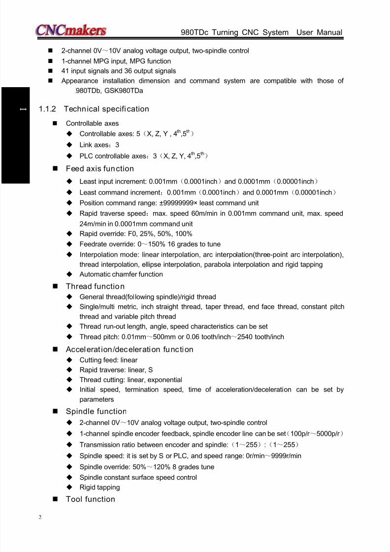
2-channel 0V~10V analog voltage output, two-spindle control
1-channel MPG input, MPG function
41 input signals and 36 output signals
Appearance installation dimension and command system are compatible with those of
GSK980TDb, GSK980TDa
1.1.2 Technical specification
Controllable axes
Controllable axes: 5(X, Z, Y , 4th,5th)
Link axes:3
PLC controllable axes:3(X, Z, Y, 4th,5th)
Feed axis function
Least input increment: 0.001mm(0.0001inch)and 0.0001mm(0.00001inch)
Least command increment:0.001mm(0.0001inch)and 0.0001mm(0.00001inch) Position command range: ±99999999× least command unit
Rapid traverse speed:max. speed 60m/min in 0.001mm command unit, max. speed
24m/min in 0.0001mm command unit
Rapid override: F0, 25%, 50%, 100%
Feedrate override: 0~150% 16 grades to tune
Interpolation mode: linear interpolation, arc interpolation(three-point arc interpolation),
thread interpolation, ellipse interpolation, parabola interpolation and rigid tapping
Automatic chamfer function
Thread function General thread(following spindle)/rigid thread
Single/multi metric, inch straight thread, taper thread, end face thread, constant pitch
thread and variable pitch thread
Thread run-out length, angle, speed characteristics can be set
Thread pitch: 0.01mm~500mm or 0.06 tooth/inch~2540 tooth/inch
Accelerat ion/deceleration function
Cutting feed: linear
Rapid traverse: linear, S
Thread cutting: linear, exponential
Initial speed, termination speed, time of acceleration/deceleration can be set by
parameters
Spindle function
2-channel 0V~10V analog voltage output, two-spindle control
1-channel spindle encoder feedback, spindle encoder line can be set(100p/r ~5000p/r )
Transmission ratio between encoder and spindle:(1~255):(1~255)
Spindle speed: it is set by S or PLC, and speed range: 0r/min~9999r/min
Spindle override: 50%~120% 8 grades tune
Spindle constant surface speed control
Rigid tapping
Tool function

8/17/2019 980TDc CNC Turning Controller User Manual
http://slidepdf.com/reader/full/980tdc-cnc-turning-controller-user-manual 18/461
Chapter 1 Programming
3
P r o gr ammi n g
Tool length compensation
Tool nose radius compensation(C)
Tool wear compensation
Tool life management
Toolsetting mode: fixed-point toolsetting, trial-cut toolsetting, reference point return
toolsetting, automatic toolsetting
Tool offset execution mode: modifying coordinate mode, tool traverse mode
Precision compensation
Backlash compensation
Memory pitch error compensation
PLC function
Two-level PLC program,up to 5000 steps,the 1st program refresh period 8ms
PLC program communication download
PLC warning and PLC alarm
Many PLC programs(up to 16PCS), the PLC program currently running can be
selected
Basic I/O:41 input signals /36 output signals
Man-machine interface
8.4″ wide screen LCD,resolution: 640×480
Chinese, English, Spanish, Russian display
Planar tool path display
Real-time clock
Operation management
Operation mode: edit, auto, MDI, machine zero return, MPG/single, manual, program
zero return
Multi-level operation privilege management
Alarm record
Program edit
Program capacity: 40MB,384 programs(including subprograms and macro programs)
Edit function: program/block word search, modification, deletion
Program format: ISO command, statement macro command programming, relative
coordinate, absolute coordinate and compound coordinate programming
Program call: macro program call with parameter, 4-level program built-in
Communication function
RS232:two-way transmitting part programs and parameters, PLC program, system
software serial upgrade
USB:U file operation, U file directly machining, PLC program, system software U
upgrade
Safety function
Emergency stop
Hardware travel limit
Software travel check Data backup and recovery

8/17/2019 980TDc CNC Turning Controller User Manual
http://slidepdf.com/reader/full/980tdc-cnc-turning-controller-user-manual 19/461
GSK980TDc Turning CNC System User Manual
4
P r o gr ammi n g
G command table
Command Func tion Command Func tion Command Function
G00 Rapid traverse
(positioning)G30
2n
, 3r
, 4 reference point
returnG71
Axial roughing cycle
(flute cycle)
G01 Linear interpolation G31 Skip function G72 Radial roughing cycle
G02 CW arc interpolation G32 Constant pitch thread cutting G73 Closed cutting cycle
G03 CCW arc interpolation G32.1 Rigid thread cutting G70 Finishing cycle
G04 Dwell, exact stop G33 Z tapping cycle G74 Axial grooving cycle
G05 Three-point arc
interpolation
G34 Thread cutting with variable
lead
G75Radial grooving cycle
G6.2 Ellipse interpolation
(CW)
G36 Automatic tool compensation X
G76 Multiple thread cutting
cycle
G6.3 Ellipse interpolation
(CCW)
G37 Automatic tool compensation Z
G80 Rigid tapping state
cancel
G7.2 Parabola interpolation(CW)
G40 Tool nose radius compensationcancel
G84 Axial rigid tapping
G7.3 Parabola interpolation
(CCW)
G41 Tool nose radius compensation
left
G88Radial rigid tapping
G12.1 Polar coordinate
interpolation G42 Tool nose radius compensation
right
G90 Axial cutting cycle
G7.1 Cylinder interpolation G50 Workpiece coordinate system
setting
G92Thread cutting cycle
G15 Polar coordinate
command cancelG52 Local workpiece coordinate
system
G94Radial cutting cycle
G16 Polar coordinate
command G54 Workpiece coordinate system 1
G96 Constant surface speed
control
G17 Plane selection
commandG55
Workpiece coordinate system 2G97 Constant surface speed
control cancel
G18 Plane selection
commandG56 Workpiece coordinate system 3 G98
Feed per minute
G19 Plane selection
commandG57 Workpiece coordinate system 4 G99
Feed per revolution
G10 Data input ONG58 Workpiece coordinate system 5
G11 Data input OFFG59 Workpiece coordinate system 6
G20 Input in inch G65 Macro command non-modal
callG21 Input in metric G66 Macro program modal call
G28Reference point return
G67 Macro program modal call
cancel
1.1.3 Environment and conditions
GSK980TDc storage delivery, working environment as follows:
Item Working conditions Storage delivery conditions
Ambient temperature 0~45 -40~+70
Ambient humidity ≤90%(no freezing) ≤95%(40 ) Atmosphere pressure 86 kPa~106 kPa 86 kPa~106 kPa
Altitude ≤1000m ≤1000m

8/17/2019 980TDc CNC Turning Controller User Manual
http://slidepdf.com/reader/full/980tdc-cnc-turning-controller-user-manual 20/461
Chapter 1 Programming
5
P r o gr ammi n g
1.1.4 Power supply
GSK980TDc can normally run in the following AC input power supply.
Voltage: within(0.85~1.1)×200V (rated AC input voltage);
Frequency: 49Hz~51Hz continuously changing
1.1.5 Guard
GSK980TDc guard level is not less than IP20.
1.2 CNC System of Machine Tools and CNC Machine Tools
CNC machine tool is an electro-mechanical integrated product, composed of Numerical Control
Systems of Machine Tools, machines, electric control components, hydraulic components, pneumatic
components, lubricant, cooling and other subsystems (components), and CNC systems of machine
tools are control cores of CNC machine tools. CNC systems of machine tools are made up of
computerized numerical control(CNC), servo (stepper) motor drive devices, servo (or stepper) motoretc.
Operational principles of CNC machine tools: according to requirements of machining
technology, edit user programs and input them to CNC, then CNC outputs motion control commands
to the servo (stepper) motor drive devices, and last the servo (or stepper) motor completes the cutting
feed of machine tool by mechanical driving device; logic control commands in user programs to
control spindle start/stop, tool selections, cooling ON/OFF, lubricant ON/OFF are output to electric
control systems of machine tools from CNC, and then the electric control systems control output
components including buttons, switches, indicators, relays, contactors and so on. Presently, the
electric control systems are employed with Programmable Logic Controller (PLC) with characteristics
of compact, convenience and high reliance. Thereof, the motion control systems and logic control
systems are the main of CNC machine tools.
GSK980TDc Turning Machine CNC system has simultaneously motion control and logic control
function to control two axes of CNC machine tool to move, and has nested PLC function. Edit PLC
programs (ladder diagram) according to requirements of input and output control of machine tool and
then download them to GSK980TDc Turning Machine CNC system, which realizes the required
electric control requirements of machine tool, is convenient to electric design of machine tool and
reduces cost of CNC machine tool.
Software used to control GSK980TDc Turning Machine CNC system is divided into system
software (NC for short) and PLC software (PLC for short). NC system is used to control the display,
communication, edit, decoding, interpolation and acceleration/deceleration, and PLC system for
controlling explanations, executions, inputs and outputs of ladder diagrams.
Standard PLC programs are loaded (except for the special order) when GSK980TDc Turning
Machine CNC System is delivered, concerned PLC control functions in following functions and
operations are described according to control logics of standard PLC programs, marking with
“Standard PLC functions” in GSK980TDc Turning CNC System User Manual. Refer to Operation
Manual of machine manufacturer about functions and operations of PLC control because the
machine manufacturer may modify or edit PLC programs again.
8/17/2019 980TDc CNC Turning Controller User Manual
http://slidepdf.com/reader/full/980tdc-cnc-turning-controller-user-manual 21/461
GSK980TDc Turning CNC System User Manual
6
P r o gr ammi n g
Fig. 1-1
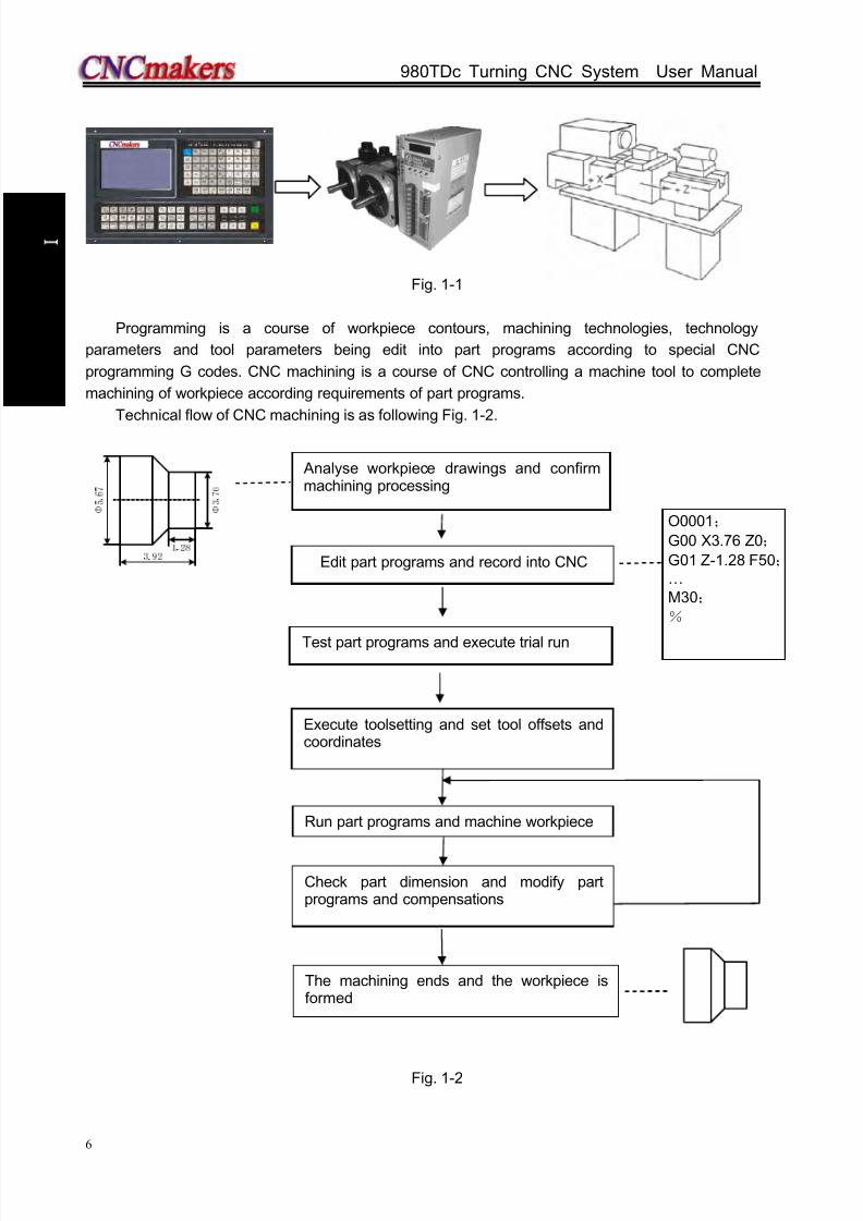
Programming is a course of workpiece contours, machining technologies, technology
parameters and tool parameters being edit into part programs according to special CNC
programming G codes. CNC machining is a course of CNC controlling a machine tool to complete
machining of workpiece according requirements of part programs.
Technical flow of CNC machining is as following Fig. 1-2.
Fig. 1-2
O0001;
G00 X3.76 Z0;
G01 Z-1.28 F50;…M30;
%
Analyse workpiece drawings and confirmmachining processing
Edit part programs and record into CNC
Test part programs and execute trial run
Check part dimension and modify partprograms and compensations
Execute toolsetting and set tool offsets andcoordinates
Run part programs and machine workpiece
The machining ends and the workpiece isformed

8/17/2019 980TDc CNC Turning Controller User Manual
http://slidepdf.com/reader/full/980tdc-cnc-turning-controller-user-manual 22/461
Chapter 1 Programming
7
P r o gr ammi n g
1.3 Programming Fundamentals
1.3.1 Coordinates defini tion
Sketch map of CNC turning machine is as follows:
Fig. 1-3
GSK980TDc uses a rectangular coordinate system composed of X, Z axis. X axis is
perpendicular with axes of spindle and Z axis is parallel with axes of spindle; negative directions of
them approach to the workpiece and positive ones are away from it.
There is a front tool post and a rear tool post of NC turning machine according to their relative
position between the tool post and the spindle, Fig. 1-4 is a coordinate system of the front tool post
and Fig. 1-5 is a rear tool post one. It shows exactly the opposite of X axes, but the same of Z axes
from figures. In the manual, it will introduce programming application with the front tool post
coordinate system in the following figures and examples.
X
Z
X
Z
Fig.1-4 Front tool post coordinate system Fig.1-5 Rear tool post coordinate system
1.3.2 Machine coordinate system, Machine Zero and machine reference point
Machine tool coordinate system is a benchmark one used for CNC counting coordinates and a
fixed one on the machine tool. Machine tool zero is a fixed point which position is specified by zero
switch or zero return switch on the machine tool. Usually, the zero return switch is installed on max.
stroke in X, Z positive direction. Machine reference point is located at the position at which the
machine zero value adding the data parameter No.114/No.115 value. When No.114/No.115 value is 0,
the machine reference point coincides with the machine zero. The coordinates of machine reference

8/17/2019 980TDc CNC Turning Controller User Manual
http://slidepdf.com/reader/full/980tdc-cnc-turning-controller-user-manual 23/461
GSK980TDc Turning CNC System User Manual
8
P r o gr ammi n g
point is the No.120/No.121 value. Machine zero return/G28 zero return is to execute the machine
reference point return. After the machine zero return/machine reference point return is completed,
GSK980TDc machine coordinate system which takes No.120 value as the reference point, which is
referred to I Programming, Section 3.13.
Note: Do not execute the machine reference point return without the reference point switch installed on the
machine tool, otherwise, the motion exceeds the travel limit and the machine to be damaged.
1.3.3 Workpiece coordinate system and Program Zero
The workpiece coordinate system is a rectangular coordinate system based on the part drawing,
also called floating coordinate system. After the workpiece is installed on the machine, the absolute
coordinates of tool’s current position is set by G50 according to the workpiece’s measure, and so the
workpiece coordinate system is established in CNC. Generally, Z axis of the workpiece coordinate
system coincides with the spindle axis. The established workpiece is valid till it is replaced by a new
one. The system can set 6 workpiece coordinate systems G54~G59 in advance. Refer to I
Programming, Section 3.18 about the details of workpiece coordinate system. A sub workpiece coordinate system is created in a workpiece coordinate system, which is called
as a local coordinate system. Refer to I Programming, Section 3.17 about the details of the local
coordinate system.
The current position of workpiece coordinate system set by G50 is the program zero.
Note: Do not execute the machine reference point return withou t using G50 to set the workpiece coordinate
system after power on, otherwise, the alarm occurs.
In the above figure, XOZ is the coordinate system of machine tool, X1O1Z1 is the workpiece
coordinate system of X axis located at the heading of workpiece, X2O2Z2 is the one of X axis located
at the ending of workpiece, O point is the machine reference point, A point is the tool nose and
Fig. 1-6
(x,z)
(x1,z1)
(x2,z2)
O2 O1Z1 (Z2)
X2 X1
z2
z1
x1/2 (x2/2)
X/2
Z
RodWorkpiece
(0,0)
X
Z

8/17/2019 980TDc CNC Turning Controller User Manual
http://slidepdf.com/reader/full/980tdc-cnc-turning-controller-user-manual 24/461
Chapter 1 Programming
9
P r o gr ammi n g
coordinates of A point in the above-mentioned coordinate systems is as follows:
A point in the machine tool coordinate system: (x,z);
A point in X1O1Z1 coordinate system: (x1,z1);
A point in X2O2Z2 coordinate system: (x2,z2).
1.3.4 Interpolation function
Interpolation is defined as a planar or three dimensional contour formed by path of 2 or multiple
axes moving at the same time, also called Contour control. The controlled moving axis is called link
axis when the interpolation is executed. The moving distance, direction and speed of it are controlled
synchronously in the course of running to form the required Composite motion path. Positioning
control is defined that motion end point of one axis or multiple axes instead of the motion path in the
course of running is controlled.
GSK980TDc X and Z axis are link axes and 2 axes link CNC system. The system possesses
linear, circular and thread interpolation function.
Linear interpolation: Composite motion path of X, Z axis is a straight line from starting point toend point.
Circular interpolation: Composite motion path of X, Z axis is arc radius defined by R or the circle
center (I, K) from starting point to end point.
Thread interpolation: Moving distance of X or Z axis or X and Z axis is defined by rotation angle
of spindle to form spiral cutting path on the workpiece surface to realize the
thread cutting. For thread interpolation, the feed axis rotates along with the
spindle, the long axis moves one pitch when the spindle rotates one rev,
and the short axis and the long axis directly interpolate.
Example:
Fig. 1-7
…
G32 W-27 F3; (B→C; thread interpolation)
G1 X50 Z-30 F100;G1 X80 Z-50; (D→E; linear interpolation)
G3 X100 W-10 R10; (E→F; circular interpolation)

8/17/2019 980TDc CNC Turning Controller User Manual
http://slidepdf.com/reader/full/980tdc-cnc-turning-controller-user-manual 25/461
GSK980TDc Turning CNC System User Manual
10
P r o gr ammi n g
…
M30;
1.3.5 Absolute programming and incremental programming
Specify coordinate values of path’s end point or target position in programming and there are 3
kinds of programming method according to coordinate values in programming: absolute programming,
incremental programming and compound programming.
Programming with X/Z axis absolute coordinate value to program (present with X, Z) is defined to
be the absolute programming;
Programming with X/Z axis incremental movement (present with U, W) is defined to be the
incremental programming;
In the system, X, Z axis separately uses the absolute programming and incremental program,
which is called the compound programming.
Example: A→B linear interpolation
Fig.1-8
Absolute programming: G01 X200 Z50;Incremental programming: G01 U100 W-50;
Compound programming: G01 X200 W-50; or G01 U100 Z50
Note: When there are command address X/ U or Z/ W at the same time, X/Z command value is valid.
Example: G50 X10 Z20;
G01 X20 W30 U20 Z30; 【End point of the block (X20, Z30)】
1.3.6 Diameter programming and radius programming
Programming methods of X coordinate values are divided into: diameter programming and
radius programming.
Diameter programming: when NO.001 Bit2 is 0, X input command value is in diameter and X
coordinate is in diameter at the moment;
Radius programming: when NO.001 Bit2 is 1, X input command value is in radius and X
coordinate is in radius at the moment.
Addresses relevant to diameter or radius programming
Address ExplanationDiameter
programming
Radius
programming
Addresses
relevant todiameter or
radius
XX coordinate
In diameter In radiusG50 setting X coordinate
UX increment In diameter In radius
X finishing allowance in G71, G72, G73 In diameter In radius
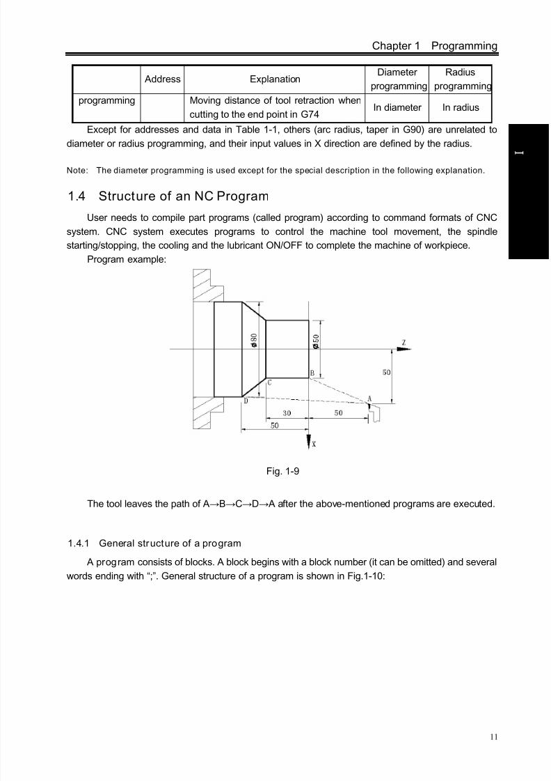
8/17/2019 980TDc CNC Turning Controller User Manual
http://slidepdf.com/reader/full/980tdc-cnc-turning-controller-user-manual 26/461
Chapter 1 Programming
11
P r o gr ammi n g
Address Explanation
Diameter
programming
Radius
programming
programming Moving distance of tool retraction when
cutting to the end point in G74In diameter In radius
Except for addresses and data in Table 1-1, others (arc radius, taper in G90) are unrelated to
diameter or radius programming, and their input values in X direction are defined by the radius.
Note: The diameter programming is used except for the special description in the following explanation.
1.4 Structure of an NC Program
User needs to compile part programs (called program) according to command formats of CNC
system. CNC system executes programs to control the machine tool movement, the spindle
starting/stopping, the cooling and the lubricant ON/OFF to complete the machine of workpiece.
Program example:
Fig. 1-9
The tool leaves the path of A→B→C→D→ A after the above-mentioned programs are executed.
1.4.1 General structure of a program A program consists of blocks. A block begins with a block number (it can be omitted) and several
words ending with “;”. General structure of a program is shown in Fig.1-10:

8/17/2019 980TDc CNC Turning Controller User Manual
http://slidepdf.com/reader/full/980tdc-cnc-turning-controller-user-manual 27/461
GSK980TDc Turning CNC System User Manual
12
P r o gr ammi n g
Fig. 1-10 Structure of a program
Program name
There are most 384 programs stored in GSK980TDc. To identify it, each program has only one
program name (there is no the same program name) beginning with command address O and the
following 4 digits.
Program number (0000~9999, the leading zero can be omitted)
Address O
Word
A word is the basic command unit to command CNC system to complete the control function,
composed of an English letter (called command address) and the following number (operation
command with/without sign). The command address describes the meaning of its following operation
command and there may be different meaning in the same command address when the different
words are combined together. All words of GSK980TDc are in Table 1-2.
Table 1-2 Word table
Address Command value range Funct ion meaning Unit
O 0~9999 Program name
N 0~9999 Block number
G 00~99 Preparatory function
X-99999999~99999999 X coordinate Relevant to IS-B, IS-C
0~99999.999(s) Pause time
Z -99999999~99999999 Z coordinate Relevant to IS-B, IS-C
Y -99999999~99999999 Y coordinate Relevant to IS-B, IS-C
U
-99999999~99999999 X increment Relevant to IS-B, IS-C
0~
99999.999(s) Pause time
-99999~99999X finishing allowance in G71,G72,
G73Relevant to IS-B, IS-C

8/17/2019 980TDc CNC Turning Controller User Manual
http://slidepdf.com/reader/full/980tdc-cnc-turning-controller-user-manual 28/461
Chapter 1 Programming
13
P r o gr ammi n g
Address Command value range Funct ion meaning Uni t
1~99999 Cutting depth in G71 Relevant to IS-B, IS-C
-99999999~99999999 X tool retraction clearance in G73 Relevant to IS-B, IS-C
W
-99999999~99999999 Z increment Relevant to IS-B, IS-C
1~99999 Cutting depth in G72 Relevant to IS-B, IS-C-99999~99999 Z finishing allowance in G71,G72,
G73Relevant to IS-B, IS-C
-99999999~99999999 Z tool retraction in G73 Relevant to IS-B, IS-C
V -99999999~99999999 Y increment Relevant to IS-B, IS-C
R
-99999999~99999999 Arc radius Relevant to IS-B, IS-C
1~99999 Tool retraction in G71, G72 Relevant to IS-B, IS-C
1~9999 (times) Roughing cycle times in G73
1~99999 Tool retraction clearance in G74,
G75Relevant to IS-B, IS-C
1~99999 Tool retraction clearance from end
point in G74, G75Relevant to IS-B, IS-C
1~99999999 Finishing allowance in G76 Relevant to IS-B, IS-C
-99999999~99999999 Taper in G90, G92, G94, G96 Relevant to IS-B, IS-C
I
-99999999~99999999 X vector between arc center and
starting pointRelevant to IS-B, IS-C
0.06~25400(tooth/inch) Metric thread teeth
K-99999999~99999999 Z vector between arc center and
starting point
Relevant to IS-B, IS-C
F
0~8000(mm/min) Feedrate per minute
0.0001~500(mm/r) Feedrate per rev
0.001~500(mm) Metric thread lead
S0~9999(r/min) Spindle speed specified
00~04 Multi-gear spindle output
T 01~32 Tool function
M
00~99 Miscellaneous function output,
program execution flow
9000~9999 Subprogram call
P
0~9999999(0.001s) Pause time
0~9999Calling times of subprogram
number
0~999 Subprogram call times
0~9999999 X circle movement in G74, G75 Relevant to IS-B, IS-C
Thread cutting parameter in G76
0~99999Initial block number of finishing in
the compound cycle command
1~9999999 Parabola mouth size in G7.2,G7.3
Relevant to IS-B, IS-C

8/17/2019 980TDc CNC Turning Controller User Manual
http://slidepdf.com/reader/full/980tdc-cnc-turning-controller-user-manual 29/461
GSK980TDc Turning CNC System User Manual
14
P r o gr ammi n g
Address Command value range Funct ion meaning Unit
Q
0~9999 End block number of finishing in
the compound cycle
0~9999999 Z circle movement in G74, G75 Relevant to IS-B, IS-C
1~9999999 First cut-in depth in G76 Relevant to IS-B, IS-C
1~9999999 Min. cut-in depth in G76 Relevant to IS-B, IS-C
0~360000 Offset angle between one-turn
signal and starting point of thread
cutting at the initial angle in G32
0~9999 Angle between long axis of the
ellipse and Z in G6.2, G6.3
0~9999 Angle between long axis of the
ellipse and Z in G7.2, G7.3
A0~99999999 Length of long radius of ellipse in
G6.2, G6.3Relevant to IS-B, IS-C
B0~99999999 Length of short radius of ellipse in
G6.2, G6.3Relevant to IS-B, IS-C
H 01~99 Operand in G65
Block
A block which is basic unit of CNC program consists of a sequence of words, ending with “;” or
“*” . There is the character “;” or “*” between blocks. “;” is used to separate blocks in the manual as
follows:
/ N0030 G0 X20 Z30 ;
One block may be with a number of words or only with “; ”ending character(EOB) instead of
words. There must be one or more blank space between many words.
There is only one for other addresses except for N, G, S, T, H, L in one block, otherwise the
system alarms. The last word in the same address is valid when there are more N, G, S, T, H, L in the
same block. The last G code is valid when there are more G codes which are in the same group inone block.
Block number
A block number consists of an address N and its following 4-digit: N0000~N9999, and the
leading zero can be omitted. The block number must be at the beginning of block, otherwise the block
is invalid.
The block number can be omitted, but there must be the block number when the program
calls/skips the target block. The increment of block number is at will and it better to increase or
decrease the sequence of block number in order to conveniently search and analyze programs.
When “Automatic number” in the switch window is set to “ON”, block numbers will beautomatically created incrementally and their increment is defined by No.42.
End of block
Block number
Block skip

8/17/2019 980TDc CNC Turning Controller User Manual
http://slidepdf.com/reader/full/980tdc-cnc-turning-controller-user-manual 30/461
Chapter 1 Programming
15
P r o gr ammi n g
Character for block sk ip
Insert “/” in the front of block and startup when some block cannot be executed (cannot be
deleted), and the system skips the block and executes the next one. The block with “/” in the front of it
is executed if the block skip switch is not started.
Character for end of a program
“%” is an ending character of program. “%” is a mark of communication ended when the program
is transmitted. The system will automatically insert “%” at the end of program.
Program annotation
A program annotation has less than 20 characters (10 Chinese characters) for each program,
lies in a bracket following its program name and is expressed only in English and digitals in CNC
system; it can be edited in Chinese in PC and displayed in Chinese in CNC system after being
downloaded.
1.4.2 Main program and subprogram
To simply the programming, when the same or similar machining path and control procedure is
used many times, its program commands are edited to a sole program to call. A program which calls
the program is the main program and the called program (end with M99) is subprogram. They both
take up the program capacity and storage space of system. The subprogram has own name, and can
be called at will by the main program and also can run separately. The system returns to the main
program to continue when the subprogram ends as follows.
Main program
O0001;
G50 X100 Z100;
M3 S1 T0101;
G0 X0 Z0;
G1 U200 Z200 F200;
M98 P21006;
G0 X100 Z100;
M5 S0 T0100;
M30;%
O1006;
G1 X50 Z50;
U100 W200;
U30 W-15 F250;
M99;
%
Subprogram
Call
Return
1.5 Program Run
1.5.1 Sequence of program run
Running the current open program must be in Auto mode. GSK980TDc cannot open two or more
programs at the same, and runs only program any time. When the first block is open, the cursor islocated in the heading of the first block and can be moved in Edit mode. In the run stop state in Auto
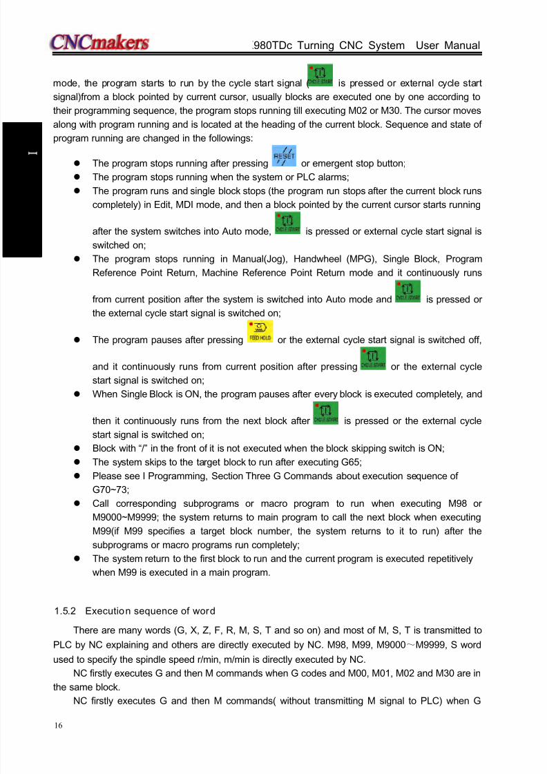
8/17/2019 980TDc CNC Turning Controller User Manual
http://slidepdf.com/reader/full/980tdc-cnc-turning-controller-user-manual 31/461
GSK980TDc Turning CNC System User Manual
16
P r o gr ammi n g
mode, the program starts to run by the cycle start signal ( is pressed or external cycle start
signal)from a block pointed by current cursor, usually blocks are executed one by one according to
their programming sequence, the program stops running till executing M02 or M30. The cursor moves
along with program running and is located at the heading of the current block. Sequence and state of
program running are changed in the followings:
The program stops running after pressing or emergent stop button;
The program stops running when the system or PLC alarms;
The program runs and single block stops (the program run stops after the current block runs
completely) in Edit, MDI mode, and then a block pointed by the current cursor starts running
after the system switches into Auto mode, is pressed or external cycle start signal is
switched on;
The program stops running in Manual(Jog), Handwheel (MPG), Single Block, Program
Reference Point Return, Machine Reference Point Return mode and it continuously runs
from current position after the system is switched into Auto mode and is pressed or
the external cycle start signal is switched on;
The program pauses after pressing or the external cycle start signal is switched off,
and it continuously runs from current position after pressing or the external cycle
start signal is switched on;
When Single Block is ON, the program pauses after every block is executed completely, and
then it continuously runs from the next block after is pressed or the external cycle
start signal is switched on;
Block with “/” in the front of it is not executed when the block skipping switch is ON;
The system skips to the target block to run after executing G65;
Please see I Programming, Section Three G Commands about execution sequence of
G70~73;
Call corresponding subprograms or macro program to run when executing M98 or
M9000~M9999; the system returns to main program to call the next block when executing
M99(if M99 specifies a target block number, the system returns to it to run) after the
subprograms or macro programs run completely; The system return to the first block to run and the current program is executed repetitively
when M99 is executed in a main program.
1.5.2 Execution sequence of word
There are many words (G, X, Z, F, R, M, S, T and so on) and most of M, S, T is transmitted to
PLC by NC explaining and others are directly executed by NC. M98, M99, M9000~M9999, S word
used to specify the spindle speed r/min, m/min is directly executed by NC.
NC firstly executes G and then M commands when G codes and M00, M01, M02 and M30 are inthe same block.
NC firstly executes G and then M commands( without transmitting M signal to PLC) when G

8/17/2019 980TDc CNC Turning Controller User Manual
http://slidepdf.com/reader/full/980tdc-cnc-turning-controller-user-manual 32/461
Chapter 1 Programming
17
P r o gr ammi n g
codes and M98, M99, M9000~M9999 are in the same block.
When G codes and M, S, T executed by PLC are in the same block, PLC defines M, S, T and G
to be executed simultaneously, or execute M, S ,T after G codes. Please see User Manual of machine
manufacturer for execution sequence of commands.
Execution sequence of G, M, S, T in the same block defined by GSK980TDc standard PLC
program is as follows:
M3, M4, M8, M10, M12, M32, M41, M42, M43, M44, S, T and G codes are executed
simultaneously;
M5, M9, M11, M13, M33 after G codes are executed;
M00, M01, M02, M30 after other commands of current block are executed.
1.6 Basic Axis Incremental System
The incremental system includes least input increment(input) and least command increment
(output). Least input increment is the least movement unit of programming movement distance, and
least command increment is the least unit of tool traversing on the machine. The two incrementsystems use mm, inch or deg.
The basic axes include X, Z, and their incremental system has IS-B, IS-C selected by No.00.1
ISC.
001 ISC
Increment 0-IS-B(μ level)
1-IS-C(0.1μ level)
In different incremental system, selecting the different axis pulse output mode can receive the
different output speed. The selection is executed by No.203 ABPx.
203 ABP5 ABP4 ABPZ ABPY ABPX
n-axis pulse 0-axis output is completed by pressing ‘PULSE+DIRECTION’
1-axis output is completed by pressing ‘AB-phase pulse’
1.6.1 Incremental system speed of basic axis
Corresponding
speed
Output mode
μ level(IS-B) 0.1μ level(IS-C)
Metric machine
(mm/min)
Inch machine
(inch/min)
Metric machine
(mm/min)
Inch machine
(inch/min)Pulse+direction 60,000 6,000 6,000 600
AB quadrature 240,000 24,000 24,000 2,400
1.6.2 Incremental system unit of basic axis
In different incremental system and different metric/inch, the least input/output increment is
different as follows:
μ level(IS-B) Least input
increment(input)
Least command
increment(output)
Metric machinemetric input(G21) 0.001 (mm) 0.001 (mm)
0.001 (deg) 0.001 (deg)
inch input(G20) 0.0001 (inch) 0.001 (mm)
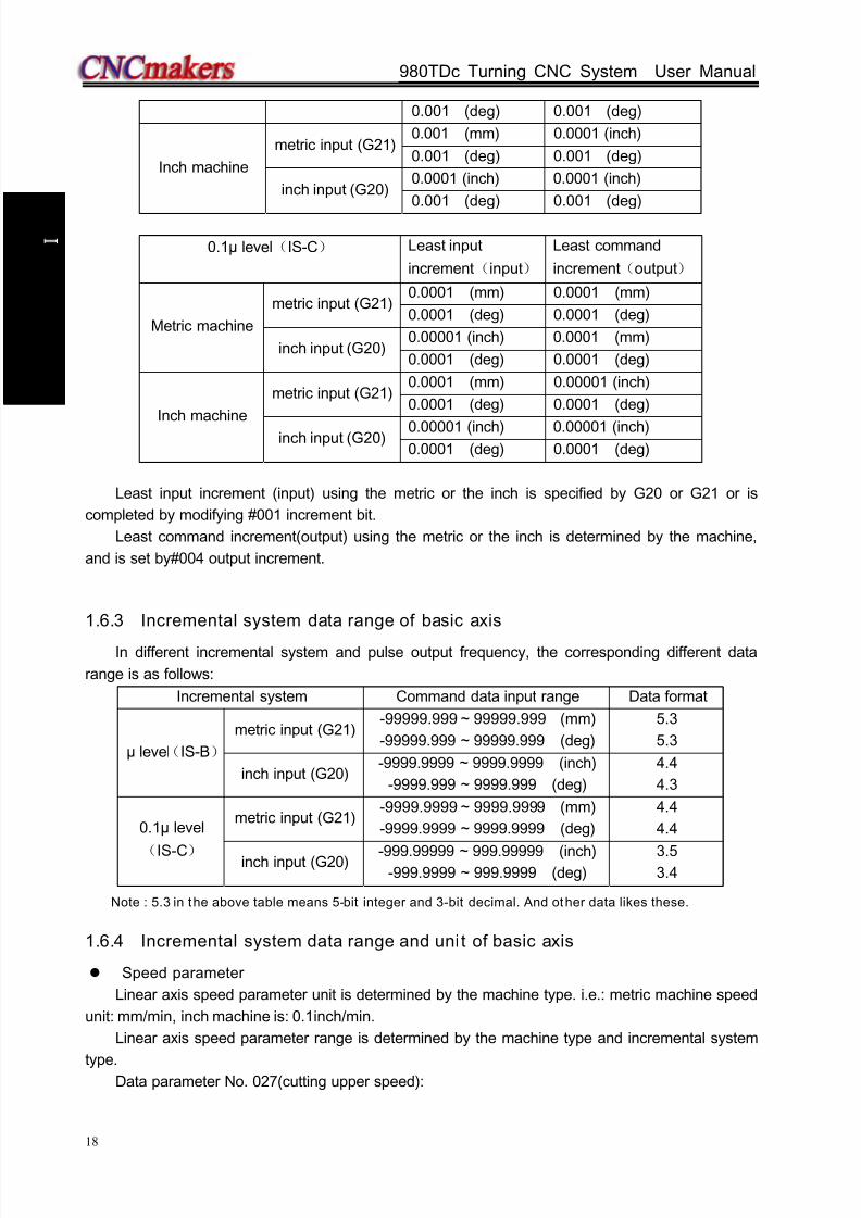
8/17/2019 980TDc CNC Turning Controller User Manual
http://slidepdf.com/reader/full/980tdc-cnc-turning-controller-user-manual 33/461
GSK980TDc Turning CNC System User Manual
18
P r o gr ammi n g
0.001 (deg) 0.001 (deg)
Inch machine
metric input (G21)0.001 (mm) 0.0001 (inch)
0.001 (deg) 0.001 (deg)
inch input (G20)0.0001 (inch) 0.0001 (inch)
0.001 (deg) 0.001 (deg)
0.1μ level(IS-C) Least input
increment(input)
Least command
increment(output)
Metric machine
metric input (G21)0.0001 (mm) 0.0001 (mm)
0.0001 (deg) 0.0001 (deg)
inch input (G20)0.00001 (inch) 0.0001 (mm)
0.0001 (deg) 0.0001 (deg)
Inch machine
metric input (G21)0.0001 (mm) 0.00001 (inch)
0.0001 (deg) 0.0001 (deg)
inch input (G20) 0.00001 (inch) 0.00001 (inch)0.0001 (deg) 0.0001 (deg)
Least input increment (input) using the metric or the inch is specified by G20 or G21 or is
completed by modifying #001 increment bit.
Least command increment(output) using the metric or the inch is determined by the machine,
and is set by#004 output increment.
1.6.3 Incremental system data range of basic axis
In different incremental system and pulse output frequency, the corresponding different data
range is as follows:
Incremental system Command data input range Data format
μ level(IS-B)
metric input (G21)-99999.999 ~ 99999.999 (mm)
-99999.999 ~ 99999.999 (deg)
5.3
5.3
inch input (G20)-9999.9999 ~ 9999.9999 (inch)
-9999.999 ~ 9999.999 (deg)
4.4
4.3
0.1μ level
(IS-C)
metric input (G21)-9999.9999 ~ 9999.9999 (mm)
-9999.9999 ~ 9999.9999 (deg)
4.4
4.4
inch input (G20) -999.99999 ~ 999.99999 (inch)-999.9999 ~ 999.9999 (deg)
3.53.4
Note : 5.3 in the above table means 5-bit integer and 3-bit decimal. And other data likes these.
1.6.4 Incremental system data range and unit of basic axis
Speed parameter
Linear axis speed parameter unit is determined by the machine type. i.e.: metric machine speed
unit: mm/min, inch machine is: 0.1inch/min.
Linear axis speed parameter range is determined by the machine type and incremental system
type.Data parameter No. 027(cutting upper speed):
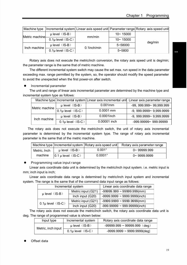
8/17/2019 980TDc CNC Turning Controller User Manual
http://slidepdf.com/reader/full/980tdc-cnc-turning-controller-user-manual 34/461
Chapter 1 Programming
19
P r o gr ammi n g
Machine type Incremental system Linear axis speed unit Parameter range Rotary axis speed unit
Metric machineμ level(IS-B)
mm/min10~ 15000
deg/min0.1μ level(IS-C) 10~ 15000
Inch machine μ level(IS-B) 0.1inch/min 5~580000.1μ level(IS-C) 5~5800
Rotary axis does not execute the metric/inch conversion, the rotary axis speed unit is deg/min;
the parameter range is the same that of metric machine.
The different incremental system switch may cause the set max. run speed in the data parameter
exceeding max. range permitted by the system, so, the operator should modify the speed parameter
to avoid the unexpected when the first power-on after switch.
Incremental parameter
The unit and range of linear axis incremental parameter are determined by the machine type and
incremental system type as follows:
Machine type Incremental system Linear axis incremental unit Linear axis parameter range
Metric machineμ level(IS-B) 0.001mm -99, 999.999~ 99,999.999
0.1μ level(IS-C) 0.0001 mm -9, 999.9999~ 9,999.9999
Inch machineμ level(IS-B) 0.0001inch -9, 999.9999~ 9,999.9999
0.1μ level(IS-C) 0.00001 inch -999.99999~ 999.99999
The rotary axis does not execute the metric/inch switch, the unit of rotary axis incremental
parameter is determined by the incremental system type. The range of rotary axis incremental
parameter is the same that of the metric machine.
Machine type Incremental system Rotary axis speed unit Rotary axis parameter range
Metric, Inch
machine
μ level(IS-B) 0.001° 0~ 99999.999
0.1 μ level(IS-C) 0.0001° 0~ 9999.9999
Programming value input range
Linear axis coordinate data unit is determined by the metric/inch input system. i.e. metric input is
mm; inch input is inch;
Linear axis coordinate data range is determined by metric/inch input system and incremental
system. The range is the same that of the command data input range as follows:
Incremental system Linear axis coordinate data range
μ level(IS-B) Metric input (G21) -99999.999 ~ 99999.999(mm)
Inch input (G20) -9999.9999 ~ 9999.9999(inch)
0.1μ level(IS-C) Metric input (G21) -9999.9999 ~ 9999.9999(mm)
Inch input (G20) -999.99999 ~ 999.99999(inch)
The rotary axis does not execute the metric/inch switch, the rotary axis coordinate data unit is
deg. The range of programmed value is shown below:
Input type Incremental system Rotary axis coordinate data range
Metric, inch inputμ level(IS-B) -99999.999 ~ 99999.999(deg)
0.1μ level(IS-C) -9999.9999 ~ 9999.9999(deg)
Offset data
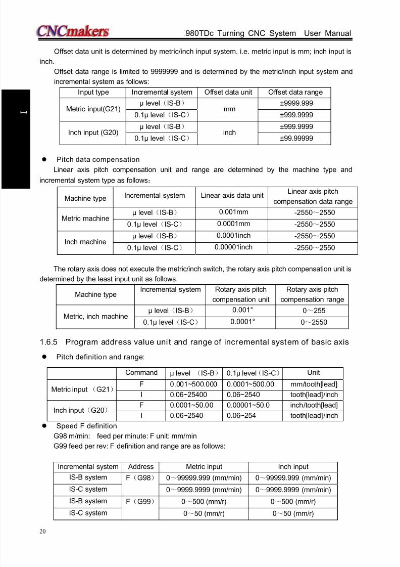
8/17/2019 980TDc CNC Turning Controller User Manual
http://slidepdf.com/reader/full/980tdc-cnc-turning-controller-user-manual 35/461
GSK980TDc Turning CNC System User Manual
20
P r o gr ammi n g
Offset data unit is determined by metric/inch input system. i.e. metric input is mm; inch input is
inch.
Offset data range is limited to 9999999 and is determined by the metric/inch input system and
incremental system as follows:
Input type Incremental system Offset data unit Offset data range
Metric input(G21)μ level(IS-B)
mm±9999.999
0.1μ level(IS-C) ±999.9999
Inch input (G20)μ level(IS-B)
inch±999.9999
0.1μ level(IS-C) ±99.99999
Pitch data compensation
Linear axis pitch compensation unit and range are determined by the machine type and
incremental system type as follows:
Machine type Incremental system Linear axis data unit
Linear axis pitch
compensation data range
Metric machineμ level(IS-B) 0.001mm -2550~2550
0.1μ level(IS-C) 0.0001mm -2550~2550
Inch machineμ level(IS-B) 0.0001inch -2550~2550
0.1μ level(IS-C) 0.00001inch -2550~2550
The rotary axis does not execute the metric/inch switch, the rotary axis pitch compensation unit is
determined by the least input unit as follows.
Machine type
Incremental system Rotary axis pitch
compensation unit
Rotary axis pitch
compensation range
Metric, inch machineμ level(IS-B) 0.001° 0~255
0.1μ level(IS-C) 0.0001° 0~2550
1.6.5 Program address value unit and range of incremental system of basic axis
Pitch definition and range:
Speed F definition
G98 m/min: feed per minute: F unit: mm/min
G99 feed per rev: F definition and range are as follows:
Incremental system Address Metric input Inch input
IS-B system F(G98)
0~99999.999 (mm/min) 0~99999.999 (mm/min)
IS-C system 0~9999.9999 (mm/min) 0~9999.9999 (mm/min)
IS-B system F(G99) 0~500 (mm/r) 0~500 (mm/r)
IS-C system 0~50 (mm/r) 0~50 (mm/r)
Command μ level (IS-B) 0.1μ level(IS-C) Unit
Metric input (G21)F 0.001~500.000 0.0001~500.00 mm/tooth[lead]
I 0.06~25400 0.06~2540 tooth[lead]/inch
Inch input(G20) F 0.0001~50.00 0.00001~50.0 inch/tooth[lead]
I 0.06~2540 0.06~254 tooth[lead]/inch

8/17/2019 980TDc CNC Turning Controller User Manual
http://slidepdf.com/reader/full/980tdc-cnc-turning-controller-user-manual 36/461
Chapter 1 Programming
21
P r o gr ammi n g
1.7 Addit ional Axis Incremental System
Least incremental system in μ level(IS-B) or 0.1μ level(IS-C), the additional axis does not
execute the link, and is not used alone. When the least incremental output of additional axis is 0.01 inthe low precision requirement and the feedrate must be fast, and so the working efficiency largely
increases. The least incremental system of additional axis does not sometime consist with the current
least incremental system. The system adds the optional function of the least incremental system of
the additional axis (Y, 4th , 5th axis) .
Additional axis incremental system is set by No..187 as follows:
187 nIS1 nIS0
nIS1, nIS0:select the least incremental system of each additional axis (n means the axis name ofeach additional axis)
nIS1 nIS0 Incremental system of axisLeast
input/output
0 0Same with current incremental
system of basic axis (XY)0 1 IS-A 0.011 0 IS-B 0.001
1 1 IS-C 0.0001
Note: The least I/O in the above table is expressed without considering the metric/inch and rotary axis.
1.7.1 Additional axis being the current incremental system
IS-B or IS-C: the relative speed and data range of additional axis is the same that the described
in Section 1.6.
1.7.2 Additional axis being IS-A incremental system
IS-A: the max. speed of additional axis is separate 10 times and 100 times of IS-B and IS-C. The
relative data and parameter range are same those of the incremental system of current basic axis
(refer to Section 1.6).
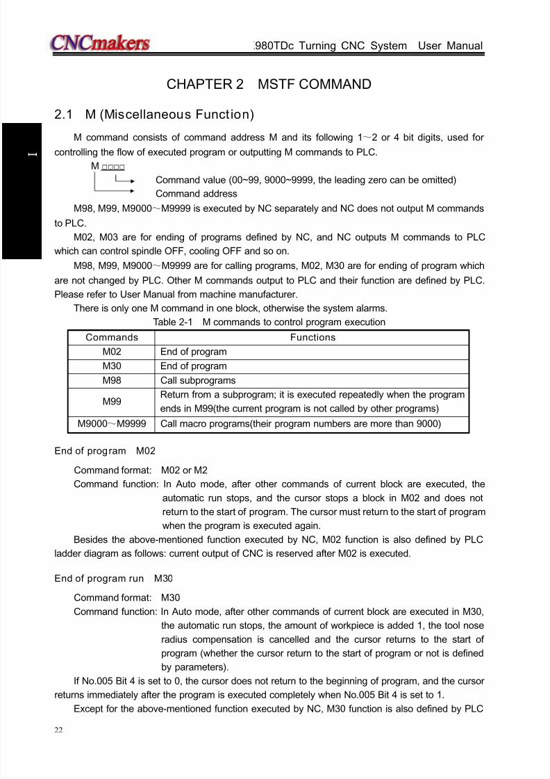
8/17/2019 980TDc CNC Turning Controller User Manual
http://slidepdf.com/reader/full/980tdc-cnc-turning-controller-user-manual 37/461
GSK980TDc Turning CNC System User Manual
22
P r o gr ammi n g
CHAPTER 2 MSTF COMMAND
2.1 M (Miscellaneous Funct ion)
M command consists of command address M and its following 1~2 or 4 bit digits, used forcontrolling the flow of executed program or outputting M commands to PLC.
M
Command value (00~99, 9000~9999, the leading zero can be omitted)
Command address
M98, M99, M9000~M9999 is executed by NC separately and NC does not output M commands
to PLC.
M02, M03 are for ending of programs defined by NC, and NC outputs M commands to PLC
which can control spindle OFF, cooling OFF and so on.
M98, M99, M9000~M9999 are for calling programs, M02, M30 are for ending of program which
are not changed by PLC. Other M commands output to PLC and their function are defined by PLC.
Please refer to User Manual from machine manufacturer.
There is only one M command in one block, otherwise the system alarms.
Table 2-1 M commands to control program execution
Commands Functions
M02 End of program
M30 End of program
M98 Call subprograms
M99Return from a subprogram; it is executed repeatedly when the program
ends in M99(the current program is not called by other programs)M9000~M9999 Call macro programs(their program numbers are more than 9000)
End of program M02
Command format: M02 or M2
Command function: In Auto mode, after other commands of current block are executed, the
automatic run stops, and the cursor stops a block in M02 and does not
return to the start of program. The cursor must return to the start of program
when the program is executed again.
Besides the above-mentioned function executed by NC, M02 function is also defined by PLC
ladder diagram as follows: current output of CNC is reserved after M02 is executed.
End of program run M30
Command format: M30
Command function: In Auto mode, after other commands of current block are executed in M30,
the automatic run stops, the amount of workpiece is added 1, the tool nose
radius compensation is cancelled and the cursor returns to the start of
program (whether the cursor return to the start of program or not is defined
by parameters).
If No.005 Bit 4 is set to 0, the cursor does not return to the beginning of program, and the cursorreturns immediately after the program is executed completely when No.005 Bit 4 is set to 1.
Except for the above-mentioned function executed by NC, M30 function is also defined by PLC

8/17/2019 980TDc CNC Turning Controller User Manual
http://slidepdf.com/reader/full/980tdc-cnc-turning-controller-user-manual 38/461
Chapter 2 MSTF Command
23
P r o gr ammi n g
ladder diagram as follows: the system closes M03, M04 or M08 signal output and outputs M05 signal
after M30 is executed.
Subprogram call M98
Command format:
M98 P
Command function: In Auto mode, after other commands are executed in M98, CNC calls
subprograms specified by P, and subprograms are executed 9999 times at
most. M98 is invalid in MDI mode.
Return from subprogram M99
Command format: M99 P
Command function: After other commands of current block in the subprogram are executed, the
system returns to the main program and continues to execute next block
specified by P, and calls a block following M98 of current subprogram when
P is not input. The current program is executed repeatedly when M99 is
defined to end of program (namely, the current program is executed withoutcalling other programs). M99 is invalid in MDI mode.
Example: Execution path of calling subprogram (with P in M99) as Fig. 2-1.
Execution path of calling subprogram (without P in M99) as Fig. 2-2.
Fig. 2-1
Called subprogram number ( 0000 ~ 9999 ) . The leading zero of
subprogram number can be omitted when the calling times is not input; the
subprogram number must be with 4 digits when the calling times is input..
Call times: 1~9999. The calling times cannot be input when it is 1.
Executed block after returning to the main program is 0000~
9999,and its leading zero can be omitted.

8/17/2019 980TDc CNC Turning Controller User Manual
http://slidepdf.com/reader/full/980tdc-cnc-turning-controller-user-manual 39/461
GSK980TDc Turning CNC System User Manual
24
P r o gr ammi n g
Fig. 2-2
Subprogram calls can be nested up to four levels as shown in Fig. 2-3.
O 1 0 0 1;.. .. . .. . .M 9 8 P 1 0 0 2 ;. . .. . .. . .. . .M 3 0 ;
M a in p ro g r a m
L e v e l 1 L ev el 2
O 1 0 0 3;.........M 9 8 P 1 0 0 4 ;............M 9 9 ;
S u b p r o g r a m
O 1 0 0 4;. ... ... ..M 9 8 P 1 0 0 5 ;. ... ... ... ..M 9 9 ;
S u bp r o g ra m
O 1 0 0 2;.. .. . .. . .M 9 8 P 1 0 0 3 ;. . .. . .. . .. . .M 9 9 ;
S u b p r o g r a m
O1005;.. .. . .. . .. . .. . .. . .. . .. . .M 9 9 ;
S u b p r o g r a m
L e v e l 3 L e ve l 4
Fig. 2-3 Subprogram nesting
Macro program call M9000~
M9999
Command format: M
9000~9999
Command function: call macro programs corresponding to command values (O9000~O9999).
Macro programs: O9000~O9999 programs are for machine manufacturer, used for editing
subprogram with special functions, called macro programs. The system must have 2-level operation
level (machine manufacturer) when editing O9000~O9999, and macro programs calling commands
are executed to call with 3~5 operation level. M9000~M9999 are invalid in MDI mode.
M commands defined by standard PLC ladder diagram
Other M commands are defined by PLC except for the above-mentioned ones(M02, M30, M98,
M99, M9000~M9999). The following M commands are defined by standard PLC, and GSK980TDc
Turning Machine CNC system is used for controlling machine tool. Refer to commands of machine
manufacturer about functions, significations, control time sequence and logic of M commands.
M commands defined by standard PLC ladder diagram.

8/17/2019 980TDc CNC Turning Controller User Manual
http://slidepdf.com/reader/full/980tdc-cnc-turning-controller-user-manual 40/461
Chapter 2 MSTF Command
25
P r o gr ammi n g
Table 2-2 M commands
Command Function Remark
M00 Program pause
M01 Program optional stop
M03 Spindle clockwise (CW) Functions interlocked
and states reservedM04 Spindle counterclockwise (CCW)
*M05 Spindle stop
M08 Cooling ON Functions interlocked
and states reserved*M09 Cooling OFF
M10 Tailstock forward Functions interlocked
and states reservedM11 Tailstock backward
M12 Chuck clamping Functions interlocked
and states reservedM13 Chuck releasing
M14 Spindle position control Functions interlocked
and states reserved*M15 Spindle speed control
M20 Spindle clamping Functions interlocked
and states reserved*M21 Spindle releasing
M24 The 2n spindle position control Functions interlocked
and states reserved*M25 The 2n spindle speed control
M32 Lubricating ON Functions interlocked
and states reserved*M33 Lubricating OFF
*M50 Spindle orientation cancel
Functions interlocked
and states reserved
M51 Spindle orientate to No. 1 point
M52 Spindle orientate to No. 2 pointM53 Spindle orientate to No. 3 point
M54 Spindle orientate to No. 4 point
M55 Spindle orientate to No. 5 point
M56 Spindle orientate to No. 6 point
M57 Spindle orientate to No. 7 point
M58 Spindle orientate to No. 8 point
M63 The 2nd spindle rotation CCWFunctions interlocked
and states reservedM64 The 2nd spindle rotation CW
*M65 The 2nd spindle stop
*M41, M42,
M43, M44Spindle automatic gear shifting
Functions interlocked
and states reserved
Note: Commands with “ *” defined by standard PLC is valid when power on.
Program stop M00
Command format: M00 or M0
Command function: After M00 is executed, the program stops and the system displays “Pause”,
and then the program continuously runs after the cycle start key is pressed.
Program optional s top M01
Command format: M01 or M1

8/17/2019 980TDc CNC Turning Controller User Manual
http://slidepdf.com/reader/full/980tdc-cnc-turning-controller-user-manual 41/461
GSK980TDc Turning CNC System User Manual
26
P r o gr ammi n g
Command function: in AUTO, MDI mode, it is valid. Press and its indicator lights and the
system enters the optional stop state, at the moment, the program stops run
and the system displays “PAUSE” after M01 is executed, after the cycle start
key is pressed, the program continuously runs. When the program optional
stop switch is not open, the program does not pause even if M01 runs.
Spindle CW, CCW and stop control M03, M04, M05
Command format: M03 or M3
M04 or M4;
M05 or M5.
Command function: M03: Spindle CW rotation;
M04: Spindle CCW rotation;
M05: Spindle stop.
Note: Refer to time sequence of output defined by standard PLC ladder in INSTALLATION &
CONNECTION.
Cooling control M08, M09
Command format: M08 or M8;
M09 or M9;
Command function: M08: Cooling ON;
M09: Cooling OFF.Note: Refer to time sequence and logic of M08, M09 defined by standard PLC ladder in
INSTALLATION & CONNECTION.
Tailstock control M10, M11
Command format: M10;
M11;
Command function: M10: tailstock going forward;
M11: tailstock going backward.
Note: Refer to time sequence and logic of M10, M11 defined by standard PLC ladder in
INSTALLATION & CONNECTION
Chuck contro l M12, M13
Command format: M12;
M13;
Command function: M12: chuck clamping;
M13: chuck releasing.Note: Refer to time sequence and logic of M12, M13 defined by standard PLC ladder in
INSTALLATION & CONNECTION.
Spindle posit ion/speed control switch M14, M15
Command format:M14;
M15;
Command function:M14:spindle is in the position control mode from speed control mode;M15:spindle is in speed control mode from the position control mode.
Note: Refer to time sequence and logic of M14, M15 defined by standard PLC ladder in INSTALLATION
8/17/2019 980TDc CNC Turning Controller User Manual
http://slidepdf.com/reader/full/980tdc-cnc-turning-controller-user-manual 42/461
Chapter 2 MSTF Command
27
P r o gr ammi n g
& CONNECTION.
Spindle clamped/released M20, M21
Command format:M20;
M21;
Command function:M20:spindle clamped
M21:spindle released
Note: Refer to time sequence and logic of M20, M21 defined by standard PLC ladder in INSTALLATION
& CONNECTION.
The 2nd spindle position/speed switch M24, M25
Command format:M24;
M25;
Command function:M24:The 2nd spindle is switched from the speed control mode to the position
control mode;
M25:The 2nd spindle is switched from the position control mode to the speed
control mode.
Note: Refer to time sequence and logic of M24, M25 defined by standard PLC ladder in INSTALLATION
& CONNECTION.
Lubricating control M32, M33
Command format:M32;
M33;
Command function:M32:lubricating ON;M33:lubricating OFF.
Note: Refer to time sequence and logic of M32, M33 defined by standard PLC ladder in INSTALLATION
& CONNECTION.
Spindle automatic gear change M41, M42, M43, M44
Command format:M4n;(n=1, 2, 3, 4)
Command function:When the system executes M4n, the spindle changes to gear n.
Note: Refer to t ime sequence and logic of M41, M42, M43, M44 defined by standard PLC ladder in
INSTALLATION&CONNECTION.
Spindle 8-point or ientation M50~
M58
Command format:M5n;(n=0~8)
Command function:M50:cancel orientation state;
M5n(n=0~8):the spindle oriented to No. n point.
Note: Refer to time sequence and logic of M50~M58 defined by standard PLC ladder in
INSTALLATION & CONNECTION.
The 2nd spindle rotation CCW, rotation CW , stop M63, M64, M65
Command format: M63;
M64;
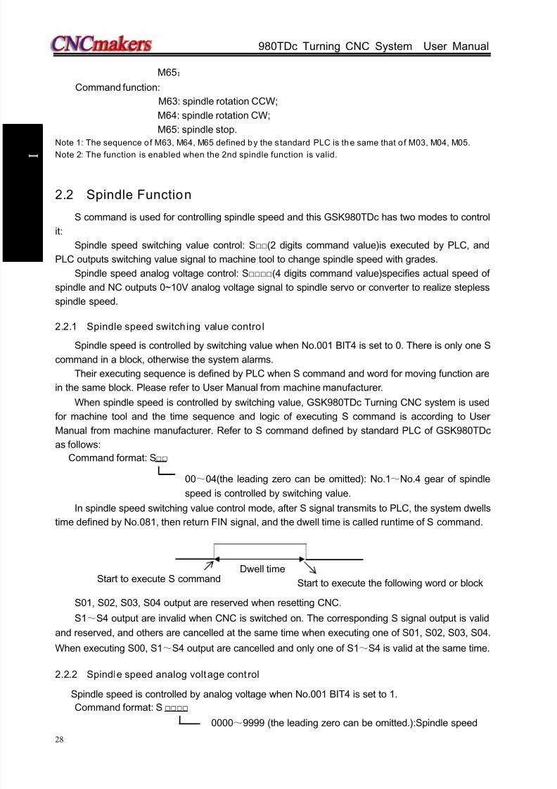
8/17/2019 980TDc CNC Turning Controller User Manual
http://slidepdf.com/reader/full/980tdc-cnc-turning-controller-user-manual 43/461
GSK980TDc Turning CNC System User Manual
28
P r o gr ammi n g
M65;
Command function:
M63: spindle rotation CCW;
M64: spindle rotation CW;
M65: spindle stop.
Note 1: The sequence of M63, M64, M65 defined by the s tandard PLC is the same that o f M03, M04, M05.
Note 2: The function is enabled when the 2nd spindle function is valid.
2.2 Spindle Function
S command is used for controlling spindle speed and this GSK980TDc has two modes to control
it:
Spindle speed switching value control: S(2 digits command value)is executed by PLC, and
PLC outputs switching value signal to machine tool to change spindle speed with grades.
Spindle speed analog voltage control: S(4 digits command value)specifies actual speed ofspindle and NC outputs 0~10V analog voltage signal to spindle servo or converter to realize stepless
spindle speed.
2.2.1 Spindle speed switch ing value contro l
Spindle speed is controlled by switching value when No.001 BIT4 is set to 0. There is only one S
command in a block, otherwise the system alarms.
Their executing sequence is defined by PLC when S command and word for moving function are
in the same block. Please refer to User Manual from machine manufacturer.
When spindle speed is controlled by switching value, GSK980TDc Turning CNC system is used
for machine tool and the time sequence and logic of executing S command is according to User
Manual from machine manufacturer. Refer to S command defined by standard PLC of GSK980TDc
as follows:
Command format: S
00~04(the leading zero can be omitted): No.1~No.4 gear of spindle
speed is controlled by switching value.
In spindle speed switching value control mode, after S signal transmits to PLC, the system dwells
time defined by No.081, then return FIN signal, and the dwell time is called runtime of S command.
S01, S02, S03, S04 output are reserved when resetting CNC.
S1~S4 output are invalid when CNC is switched on. The corresponding S signal output is valid
and reserved, and others are cancelled at the same time when executing one of S01, S02, S03, S04.
When executing S00, S1~S4 output are cancelled and only one of S1~S4 is valid at the same time.
2.2.2 Spindle speed analog voltage control
Spindle speed is controlled by analog voltage when No.001 BIT4 is set to 1.Command format: S
0000~9999 (the leading zero can be omitted.):Spindle speed
Dwell timeStart to execute S command Start to execute the following word or block
8/17/2019 980TDc CNC Turning Controller User Manual
http://slidepdf.com/reader/full/980tdc-cnc-turning-controller-user-manual 44/461
Chapter 2 MSTF Command
29
P r o gr ammi n g
analog voltage control
Command function: The spindle speed is defined, and the system outputs 0~10V analog voltage
to control spindle servo or converter to realize the stepless timing. S
command value is not reserved, and it is 0 after the system is switched on.
When the spindle speed analog voltage control is valid, there are 2 methods to input the spindle
speed: the spindle fixed speed is defined by S command( r/min), and is invariant without changing S
command value, which is called constant speed control(G97 modal); other is the tangent speed of
tool relative to the outer circle of workpiece defined by S command, which is called constant surface
speed control (G96 modal), and the spindle speed is changed along with the absolute coordinates
value of X absolute coordinates in programming path when cutting feed is executed in the constant
surface speed.
Please refer to Section 2.2.3.
The system can execute 4 gears spindle speed. Count the analog voltage value corresponding
to the specified speed according to setting value(corresponding to No.037~No.040) of max. spindle
speed (analog voltage is 10V)of current gear, and then output to spindle servo or converter to ensurethat the spindle actual speed and the requirement are the same.
After the system is switched on, the analog output voltage is 0V. The analog output voltage is
reserved (except that the system is in cutting feed in the surface speed control mode and the
absolute value of X absolute coordinates is changed) after S command is executed. The analog
output voltage is 0V after S0 is executed. The analog output voltage is reserved when the system
resets and emergently stops.
Parameters relative to the analog voltage control of spindle speed:
System parameter No.021: offset value of output voltage with max. spindle speed (the analog
output voltage is 10V);
System parameter No.036: offset value of output voltage with spindle speed 0 (the analog outputvoltage is 10V);
System parameter No.037~No.040: max. spindle speed (the analog output voltage is 10V) with
spindle 1~4 gears(corresponding to M41~M44).
2.2.3 Constant surface speed control G96, constant rotational speed control G97
Command format: G96 S__; (S0000~S9999, the leading zero can be omitted.)
Command function: The constant surface speed control is valid, the cutting surface speed is
defined (m/min) and the constant rotational speed control is cancelled.
G96 is modal G code. If the current modal is G96, G96 cannot be input.
Command format: G97 S__; (S0000~S9999, the leading zero can be omitted.)
Command function: The constant surface speed control is cancelled, the constant rotational
speed control is valid and the spindle speed is defined (r/min). G96 is
modal G code. If the current modal is G97, G97 cannot be input.
Command format: G50 S__; (S0000~S9999, the leading zero can be omitted.)
Command function: define max. spindle speed limit (r/min) in the constant surface speed control
and take the current position as the program reference point.
G96, G97 are the modal word in the same group but one of them is valid. G97 is the initial word
and the system defaults G97 is valid when the system is switched on.
When the machine tool is turning it, the workpiece rotates based on the axes of spindle as thecenter line, the cutting point of tool cutting workpiece is a circle motion around the axes, and the
instantaneous speed in the circle tangent direction is called cutting surface (for short surface
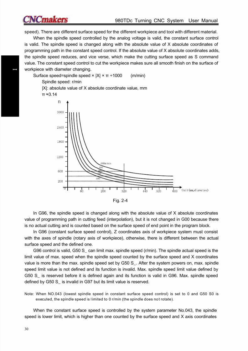
8/17/2019 980TDc CNC Turning Controller User Manual
http://slidepdf.com/reader/full/980tdc-cnc-turning-controller-user-manual 45/461
GSK980TDc Turning CNC System User Manual
30
P r o gr ammi n g
speed). There are different surface speed for the different workpiece and tool with different material.
When the spindle speed controlled by the analog voltage is valid, the constant surface control
is valid. The spindle speed is changed along with the absolute value of X absolute coordinates of
programming path in the constant speed control. If the absolute value of X absolute coordinates adds,
the spindle speed reduces, and vice verse, which make the cutting surface speed as S command
value. The constant speed control to cut the workpiece makes sure all smooth finish on the surface of
workpiece with diameter changing.
Surface speed=spindle speed × |X| × π ÷1000 (m/min)
Spindle speed: r/min
|X|: absolute value of X absolute coordinate value, mm
π ≈3.14
Fig. 2-4
In G96, the spindle speed is changed along with the absolute value of X absolute coordinates
value of programming path in cutting feed (interpolation), but it is not changed in G00 because there
is no actual cutting and is counted based on the surface speed of end point in the program block.
In G96 (constant surface speed control), Z coordinates axis of workpiece system must consist
with the axes of spindle (rotary axis of workpiece), otherwise, there is different between the actual
surface speed and the defined one.G96 control is valid, G50 S_ can limit max. spindle speed (r/min). The spindle actual speed is the
limit value of max. speed when the spindle speed counted by the surface speed and X coordinates
value is more than the max. spindle speed set by G50 S_. After the system powers on, max. spindle
speed limit value is not defined and its function is invalid. Max. spindle speed limit value defined by
G50 S_ is reserved before it is defined again and its function is valid in G96. Max. spindle speed
defined by G50 S_ is invalid in G97 but its limit value is reserved.
Note: When NO.043 (lowest spindle speed in constant surface speed control) is set to 0 and G50 S0 is
executed, the spindle speed is l imited to 0 r/min (the spindle does no t rotate).
When the constant surface speed is controlled by the system parameter No.043, the spindle
speed is lower limit, which is higher than one counted by the surface speed and X axis coordinates

8/17/2019 980TDc CNC Turning Controller User Manual
http://slidepdf.com/reader/full/980tdc-cnc-turning-controller-user-manual 46/461
Chapter 2 MSTF Command
31
P r o gr ammi n g
value.
Example:
G0230
Z axis
A
BC
50D
X axis
Fig. 2-5
O0001 ; (Program name)N0010 M3 G96 S300; (Spindle rotates clockwise, the constant surface speed control is
valid and the surface speed is 300 m/min)
N0020 G0 X100 Z100; (Rapid traverse to A point with spindle speed 955 r/min)
N0030 G0 X50 Z0; (Rapid traverse to B point with spindle speed 1910 r/min)
N0040 G1 W-30 F200; (Cut from B to C with spindle speed 1910 r/min)
N0050 X80 W-20 F150; (Cut from C to D with spindle speed 1910 r/min and surface speed
1194 r/min)
N0060 G0 X100 Z100; (Rapid retract to A point with spindle speed 955 r/min)
N0110 M30; (End of program, spindle stopping and cooling OFF)
N0120 %
Note 1: S value commanded in G96 is also reserved in G97. Its value is resumed when the system is in G96
again; Example:
G96 S50; (Cutting surface speed 50m/min)
G97 S1000; (Spindle speed 1000 r/min)
G96 X3000; (Cutting surface speed 50m/min)
Note 2: The constant surface speed contro l is valid when the machine tool is locked (X, Z do not move when
their motion command are executed);
Note 3: To gain the precise thread machining, it should not be adopted with the constant surface speed
control but the constant rotational speed (G97) in the course of thread cutting;
Note 4: From G96 to G97, if none of S command (r/min) is commanded in the program block in G97, the last
spindle speed in G96 is taken as S command in G97, namely, the spindle speed is not changed at this
time;
Note 5: In G96, when the spindle speed counted by the cutting surface speed is more than max. speed of
current spindle gear (system parameter No.037~No.040), at this time, the spindle speed is limited to
max. one of current spindle gear.
2.2.4 Spindle override
When the spindle speed analog voltage control is valid, the spindle actual speed can be tuned
real time by the spindle override and is limited by max spindle speed of current gear after the spindle
override is tuned, and it also limited by limited values of max. and min. spindle speed in constant
surface speed control mode.
The system supplies 8 steps for spindle override (50%~120% increment of 10%). The actual

8/17/2019 980TDc CNC Turning Controller User Manual
http://slidepdf.com/reader/full/980tdc-cnc-turning-controller-user-manual 47/461
GSK980TDc Turning CNC System User Manual
32
P r o gr ammi n g
steps and tune of spindle override are defined by PLC ladder and introductions from machine
manufacturer should be referred when using it. Refer to the following functions of GSK980TDc
standard PLC ladder.
The spindle actual speed specified by GSK980TDc standard PLC ladder can be tuned real time
by the spindle override tune key at 8 steps in 50%~120% and it is not reserved when the spindle
override is switched off. Refer to the operations of spindle override in OPERATION.
2.2.5 Multiple spindle control function
GSK980TDc can control up to two analog spindles. One S code is used to command one of them
which are selected by PLC signal and which have the gear change function.
Because GSK980TDc has only one spindle encoder interface, the 2nd spindle has no encoder
feedback and the spindle speed is not displayed.
Being the speed command, S code is sent to the spindle selected by the spindle selection signal
(SWS1, SWS2 <G27#0, G27#1>), and each spindle rotates with the specified speed. When the
spindle has not received the spindle selection signal, it rotates with the previous speed, which makesthe spindle rotates with different speed in different time. Each spindle has its own stop signal and
enabling signal.
When 001#4 is set to 1, setting MSEN(196#4)to 1 can start the multiple spindle control
function.
The spindle control has several methods which are set by MSI(196#7)as follows:
Multiple spindle control method A
When SWS1 signal selects the 1st spindle, SIND signal is used to determine that the spindle
analog voltage is controlled by PLC or CNC, R011 to R121 signals are used to set the spindle analog
voltage. These signals do not influence the 2nd spindle.
Multiple spindle control method A is shown below.
Multiple spindle control method B
Each spindle has separate SIND signal.When the spindle selection signal, the 1st spindle or the 2nd spindle SIND signal is set to 1, SIND
signals separately determine each spindle to be controlled by PLC or CNC.
Multiple spindle control method B is shown below.
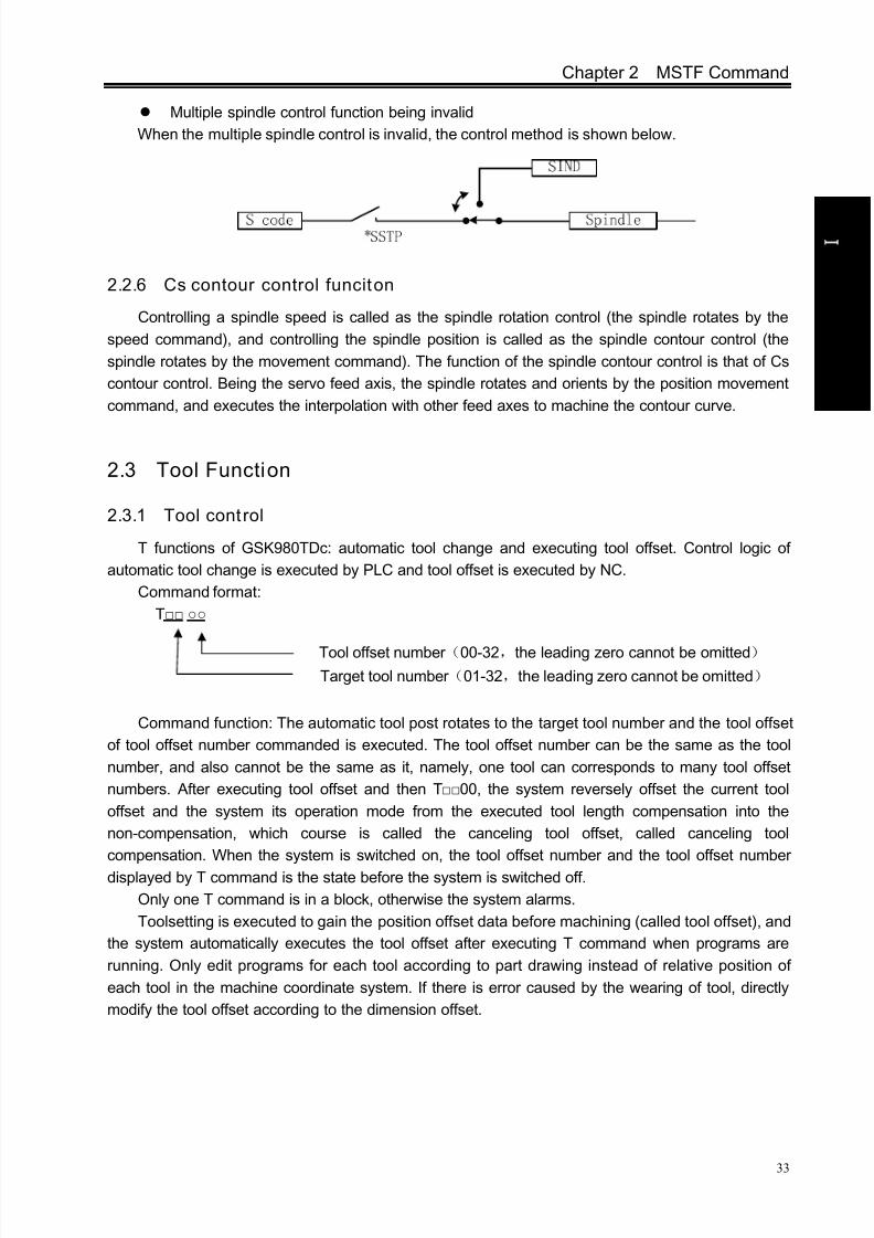
8/17/2019 980TDc CNC Turning Controller User Manual
http://slidepdf.com/reader/full/980tdc-cnc-turning-controller-user-manual 48/461
Chapter 2 MSTF Command
33
P r o gr ammi n g
Target tool number (01-32,the leading zero cannot be omitted)
Multiple spindle control function being invalid
When the multiple spindle control is invalid, the control method is shown below.
2.2.6 Cs contour control funciton
Controlling a spindle speed is called as the spindle rotation control (the spindle rotates by the
speed command), and controlling the spindle position is called as the spindle contour control (the
spindle rotates by the movement command). The function of the spindle contour control is that of Cs
contour control. Being the servo feed axis, the spindle rotates and orients by the position movement
command, and executes the interpolation with other feed axes to machine the contour curve.
2.3 Tool Function
2.3.1 Tool control
T functions of GSK980TDc: automatic tool change and executing tool offset. Control logic of
automatic tool change is executed by PLC and tool offset is executed by NC.
Command format:
T
Command function: The automatic tool post rotates to the target tool number and the tool offset
of tool offset number commanded is executed. The tool offset number can be the same as the tool
number, and also cannot be the same as it, namely, one tool can corresponds to many tool offset
numbers. After executing tool offset and then T00, the system reversely offset the current tool
offset and the system its operation mode from the executed tool length compensation into the
non-compensation, which course is called the canceling tool offset, called canceling tool
compensation. When the system is switched on, the tool offset number and the tool offset number
displayed by T command is the state before the system is switched off.
Only one T command is in a block, otherwise the system alarms.
Toolsetting is executed to gain the position offset data before machining (called tool offset), and
the system automatically executes the tool offset after executing T command when programs are
running. Only edit programs for each tool according to part drawing instead of relative position of
each tool in the machine coordinate system. If there is error caused by the wearing of tool, directly
modify the tool offset according to the dimension offset.
Tool offset number (00-32,the leading zero cannot be omitted)

8/17/2019 980TDc CNC Turning Controller User Manual
http://slidepdf.com/reader/full/980tdc-cnc-turning-controller-user-manual 49/461
GSK980TDc Turning CNC System User Manual
34
P r o gr ammi n g
Fig.2-6 tool offset
The tool offset is used for the programming. The offset corresponding to the tool offset number in
T command is added or subtracted on the end point of each block. Tool offset in X direction in
diameter or radius is set by No.004 Bit4. For tool offset in diameter or radius in X direction, the
external diameter is changed along with diameter or radius when the tool length compensation is
changed.
Example: When the state parameter No.004 Bit4 is set to 0 and X tool length compensation
value is 10mm, the external diameter of workpiece is 10mm; when No. 004 is set to 1 and X tool
length compensation value is 10mm, the external diameter of workpiec is 20mm. Fig.2-5 is the course
of creating, executing and canceling tool offset in traverse mode.
Fig. 2-7 Creation, execution and cancellation of tool length compensation
G01 X100 Z100 T0101; (Block 1, start to execute the tool offset)
G01 W150; (Block 2, tool offset Block 2, tool offset)
G01 U150 W100 T0100; (Block 3, canceling tool offset)
There are two methods defined by No.003 Bit4 to execute the tool length compensation:Bit4=0: The tool length compensation is executed by the tool traversing;
Bit4=1: The tool length compensation is executed by modifying the coordinates;
Example:
Table 2-4
Tool offset number X Z
00 0.000 0.000
01 0.000 0.000
02 12.000 -23.000
03 24.560 13.452

8/17/2019 980TDc CNC Turning Controller User Manual
http://slidepdf.com/reader/full/980tdc-cnc-turning-controller-user-manual 50/461
Chapter 2 MSTF Command
35
P r o gr ammi n g
Fig. 2-7 Tool traversing mode
Fig. 2-8 Modifying the coordinates mode
In Edit and Auto mode, a sole T word in executing tool offset (it is not with the motion command
in the same block) is relative to No.004 BIT3 setting (as Fig.2-6 and Fig.2-7). When No.003 Bit4=1
and a sole T command is executed, the tool offset number is displayed in poor, which is cleared
out(tool offset number is still displayed in poor when tool offset is not executed for one axis, the
previous bit of tool offset number is for X axis tool compensation and the next one is for Z axis tool
compensation) after executing tool offset.
Example: When No.003 Bit4 is 1 and a sole T0101 is executed, the system displays after
State of TT0202
Coordinates
displaying(Incrementalcoordinates)U: 12.000W: -23.000(Absolutecoordinates)X: 0.000Z: 0.000
State of TT0303
Coordinates
displaying(Incrementalcoordinates)U: 24.560W: 13.452(Absolutecoordinates)X: 0.000Z: 0.000
State of TT0100
Coordinates
displaying(Incrementalcoordinates)U: 0.000W: 0.000(Absolutecoordinates)X: 0.000Z: 0.000
01 tool withoutthe toolcompensation
Change 2 tooland execute itsoffset by the tooltraversing with 12mmin X positive directionand 23mm in Znegative direction
Change 3 tooland execute its offset
by the tool traversingwith 12.56mm in Xpositive direction and36.452mm in Z positivedirection
State of TT0100
Coordinatesdisplaying(Incrementalcoordinates)U: 0.000W: 0.000(Absolutecoordinates)X: 0.000Z: 0.000
01 tool
without the toolcompensation
State of TT0202
Coordinatesdisplaying(Incrementalcoordinates)U: 0.000W: 0.000
(Absolutecoordinates)X: -12.000Z: 23.000
Change 2 tool
and execute itsoffset by modifyingthe coordinates
State of TT0303
Coordinatesdisplaying(Incrementalcoordinates)U: 0.000W: 0.000(Absolutecoordinates)X: -24.560Z: -13.452
Change 3 tool
and execute itsoffset bymodifying thecoordinates

8/17/2019 980TDc CNC Turning Controller User Manual
http://slidepdf.com/reader/full/980tdc-cnc-turning-controller-user-manual 51/461
GSK980TDc Turning CNC System User Manual
36
P r o gr ammi n g
executing Z axis as follows:
Executing a sole T0101 and tool offsets of two axes are not executed
Executing W0 after T0101, X tool offset is not executed but that of Z is done
When T command and the motion command are in the same block and execute tool offset by
modifying coordinates, the motion command and T command are executed at the same time, the
system executes by adding the current tool offset to coordinates of motion command and whether the
traverse speed is employed the cutting feedrate or the rapid traverse speed defined by the motion
command.
When T command and the motion command are in the same block and execute tool offset by
traversing tool, the motion command or T command is executed separately. Firstly tool change is
executed and then the motion command is executed. The tool offset is executed at current rapid
traverse speed.The tool offset is cancelled after one of the following operations is executed:
1. Execute T00 command;

8/17/2019 980TDc CNC Turning Controller User Manual
http://slidepdf.com/reader/full/980tdc-cnc-turning-controller-user-manual 52/461
Chapter 2 MSTF Command
37
P r o gr ammi n g
2. Execute G28 or manual machine reference point return (only the tool offset of coordinate
axis which is executed machine reference point return is cancelled, and another one which is
not executed machine reference point return is not cancelled);
When No.084 is not 1 (2~32) and target tool number is not equal to current display tool number,
the control sequence and logic of tool post is defined by PLC ladder diagram after commanding T
command, please see User Manual of machine tool manufacturer. GSK980TDc standard PLC ladder
diagram defines as follows: clockwise rotation for selecting tool, counterclockwise rotation for tool
post clamping, directly inputting tool selection signal for tool change. Please refer to
INSTALLATION & CONNECTION.
When the system is employed with line-up tool post, No.084 should be set to 1 and different tool
number is executed by different tool offset as T0101, T0102, T0103.
2.3.2 Tool life management
1. Starting tool life management funct ion
The state parameter No.002 Bit0 (TLIF) is the market whether the tool life management functionis valid or not, the corresponding tool life management window is not displayed when it is invalid.
002 Tool life management
Bit 0 Tool life management function is not valid.
1 Tool life management function is valid.
2. Tool life management display window
Press repetitively into the tool life management display window .
1)
“ Tool compensation->tool life” windowThe current window displays the life management data of current used tool life management and
defined tool groups. The window is shown below:
Current tool state: display the current used tool life management data;
Tool number: current used tool and tool compensation number;Group: the group where the tool is;
Life: tool life data, the specified value can be time or number of times according to the different
count N value; press to record the time or clear the times.
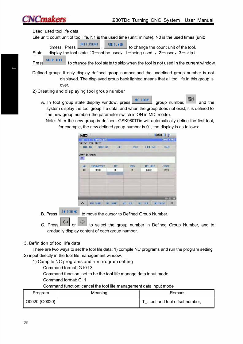
8/17/2019 980TDc CNC Turning Controller User Manual
http://slidepdf.com/reader/full/980tdc-cnc-turning-controller-user-manual 53/461
GSK980TDc Turning CNC System User Manual
38
P r o gr ammi n g
Used: used tool life data.
Life unit: count unit of tool life, N1 is the used time (unit: minute), N0 is the used times (unit:
times) . Press , to change the count unit of the tool.
State: display the tool state(0-not be used,1-being used ,2-used,3-skip).
Press to change the tool state to skip when the tool is not used in the current window.
Defined group: It only display defined group number and the undefined group number is not
displayed. The displayed group back lighted means that all tool life in this group is
over.
2) Creating and displaying tool group number
A. In tool group state display window, press , group number, and the
system display the tool group life data, and when the group does not exist, it is defined to
the new group number( the parameter switch is ON in MDI mode).
Note: After the new group is defined, GSK980TDc will automatically define the first tool,for example, the new defined group number is 01, the display is as follows:
B. Press to move the cursor to Defined Group Number.
C. Press or to select the group number in Defined Group Number, and to
gradually display content of each group number.
3. Definition of tool li fe data
There are two ways to set the tool life data: 1) compile NC programs and run the program setting;
2) input directly in the tool life management window.
1) Compile NC programs and run program setting
Command format: G10 L3
Command function: set to be the tool life manage data input mode
Command format: G11
Command function: cancel the tool life management data input mode
Program Meaning Remark
O0020 (O0020) T_: tool and tool offset number;

8/17/2019 980TDc CNC Turning Controller User Manual
http://slidepdf.com/reader/full/980tdc-cnc-turning-controller-user-manual 54/461
Chapter 2 MSTF Command
39
P r o gr ammi n g
G10 L3; Set to be the tool life management data
input mod
P01; Tool group number, too group number
setting range(1~32)
N_: tool life count mode, N0 is the
used time(minute) to count tool
life and N1 is the used number
of times to count the tool
life(unit: min)
T0101 L500 N0; Tool number, life, mode(number of
times) setting
T0201 L600 N1; Tool number, life and mode(min) setting
P02; Another tool group number
T0303 L200 N0; L_: tool life data, the specified value
can be time or number of times
according to the different count
N value
T0304 L300 N0;
G11; Cancel the tool life management data
input mode
M30;
Note 1: The tool group numbers specified by P may not be the continuous, but it is better to gradually
increase the sequence number to easily search the too l group number.
Note 2: The tool life is 0 when the life data L_ is omitted, and the tool mode is 0 (minute) when the specified
mode N_ is omitted, at the time, the system only counts and doest not alarm for the output.
Note 3: Other commands between G10 L3 and G11 are ignored.
Note 4: Running the tool li fe preset program (such as O0020) completely clear all previous life data and
preset the life data according to the program requirements.
Note 5: Prevent the life data from being modified manually when the part programs are running until the run
state stops (except fo r runn ing the too l life preset programs).
Note 6: All tool life data is stored when power-down.
2) Input tool life management data in the tool life management window
Input directly the tool life management data in tool compensation- >tool life window in MDI
mode, parameter switch ON and 3-level operation limit.
A. alter data:
In tool compensation -> tool life window, press to move the tool to the life position,
input directly data, such as 500, press to confirm the input. Press to
complete data input (tool offset, life) .
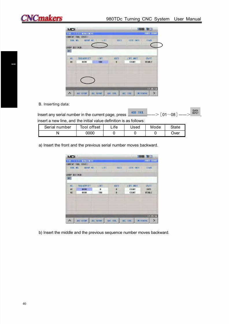
8/17/2019 980TDc CNC Turning Controller User Manual
http://slidepdf.com/reader/full/980tdc-cnc-turning-controller-user-manual 55/461
GSK980TDc Turning CNC System User Manual
40
P r o gr ammi n g
B. Inserting data:
Insert any serial number in the current page, press ――>[01~08]――> ,
insert a new line, and the initial value definition is as follows:
Serial number Tool offset Life Used Mode State
N 0000 0 0 0 Over
a) Insert the front and the previous serial number moves backward.
b) Insert the middle and the previous sequence number moves backward.

8/17/2019 980TDc CNC Turning Controller User Manual
http://slidepdf.com/reader/full/980tdc-cnc-turning-controller-user-manual 56/461
Chapter 2 MSTF Command
41
P r o gr ammi n g
c) Insert behind
C. Delete data:
a) Delete data in all groups.
In tool compensation-> tool life window, press to delete all defined data.
Before operation
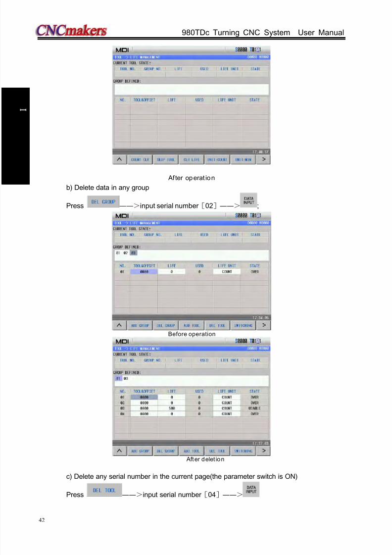
8/17/2019 980TDc CNC Turning Controller User Manual
http://slidepdf.com/reader/full/980tdc-cnc-turning-controller-user-manual 57/461
GSK980TDc Turning CNC System User Manual
42
P r o gr ammi n g
Af ter operat ion
b) Delete data in any group
Press ――>input serial number [02]――> ;
Before operation
After delet ion
c) Delete any serial number in the current page(the parameter switch is ON)
Press ――>input serial number [04]――>
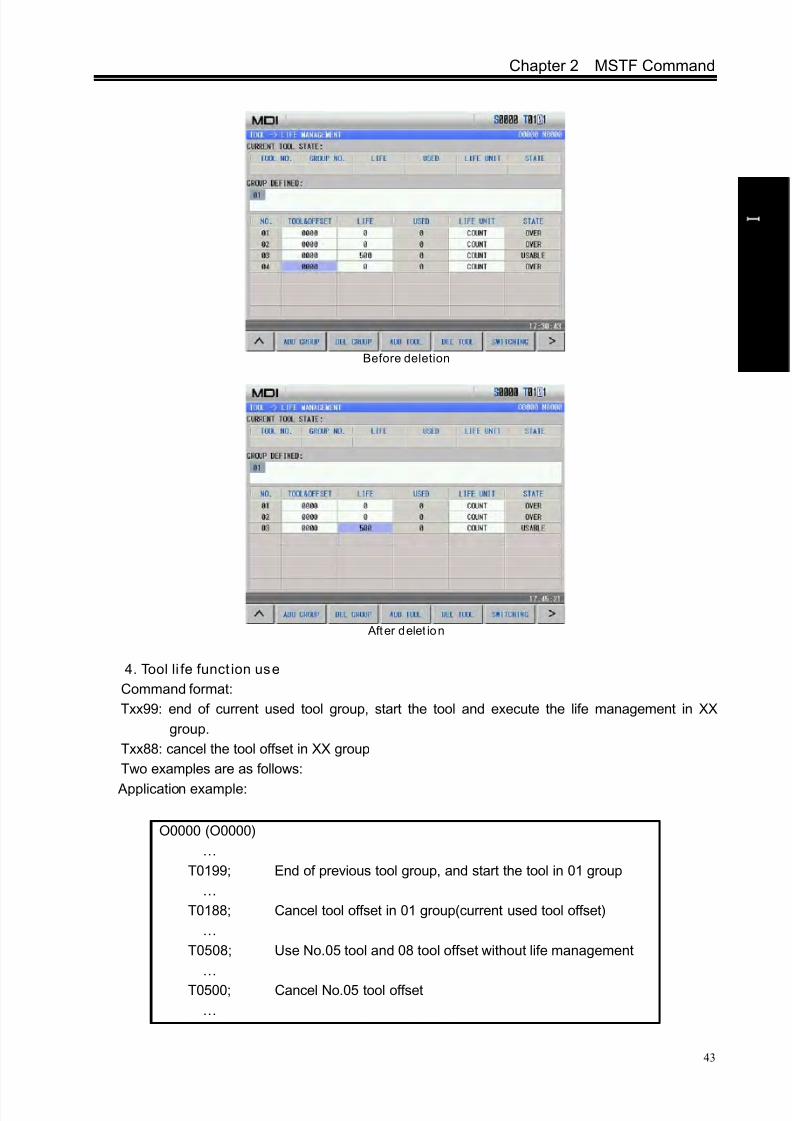
8/17/2019 980TDc CNC Turning Controller User Manual
http://slidepdf.com/reader/full/980tdc-cnc-turning-controller-user-manual 58/461
Chapter 2 MSTF Command
43
P r o gr ammi n g
Before deletion
After delet ion
4. Tool li fe funct ion use
Command format:
Txx99: end of current used tool group, start the tool and execute the life management in XX
group.
Txx88: cancel the tool offset in XX group
Two examples are as follows:
Application example:
O0000 (O0000)
…
T0199; End of previous tool group, and start the tool in 01 group
…
T0188; Cancel tool offset in 01 group(current used tool offset)
…
T0508; Use No.05 tool and 08 tool offset without life management
…
T0500; Cancel No.05 tool offset
…

8/17/2019 980TDc CNC Turning Controller User Manual
http://slidepdf.com/reader/full/980tdc-cnc-turning-controller-user-manual 59/461
GSK980TDc Turning CNC System User Manual
44
P r o gr ammi n g
T0299; End of No.05 tool and start the tools in 02 group
…
T0199;End of tools in No.02 group, start tools in No.02 group, and
start the next tool when there are many tools in No.01 group.
…
5. Tool life count:
When the count result is for the used life value being more than or equal to the setting value
of the life data, the next tool group number selects the standby tool in the commanded selection
tool group and the new selected tool will be counted, the count will be continuously executed and
the system alarms to output to PLC when all tool life in the tool groups reaches and there is no
standby tools. Executing the counting in MDI mode is determined by No.002 Bit3 (MDITL).
002 MDITL
MDITL=0 Tool life management is invalid in MDI mode.MDITL=1 Tool life management is valid in MDI mode.
The tool life count has two methods including time and number of times.
A. Time count
Use the time (minute) to count the tool life in cutting feed mode(such as G01, G02, G03,
G32, G33, G34 and so on), and do not count it in G00, G04, single block stop, machine lock,
auxiliary lock, dry run and so on.
B. Number of times count
There are two methods about the number of times count which is determined by No.002 Bit2
(LIFC).
002 LIFC
LIFC=0 Tool life management count mode 1
Execute the tool select (Txx99) to change the tool number, execute the count in the cutting
feed mode (except for machine lock, auxiliary lock, dry run state). The count is not executed
when the tool number is changed and the system is not in the cutting feed mode.
Application example:
Use 3 times in 01 tool group use once in 01 tool group
LIFC=1 Tool life management count 2
The tool group adds when the machining program runs to M30(M99), when the system
…
T0199
…
T0199
…
T0199
…
…
T0199
…
T0299
…
T0199
…
T0299
…
T0199
…
1st times
2nd times
3rd times
8/17/2019 980TDc CNC Turning Controller User Manual
http://slidepdf.com/reader/full/980tdc-cnc-turning-controller-user-manual 60/461
Chapter 2 MSTF Command
45
P r o gr ammi n g
resets halfway, the number of time does not add, the count is not executed in machine lock,
auxiliary lock and dry run mode.
6. G, F signals relevant to tool life function
a) Tool change signal TLCH(F064#0)
[Type] output signal
[Function] inform PLC that the last tool life ends of in this group
[Output condition] the signal is set to 1, the last tool life in one group ends, all other tool
life ends.
b) New tool selection signal TLNW(F064#1)
[Type] output signal
[Function] inform a new tool in some tool group has been selected
[Output condition] the signal is set to 1 and a new tool in some tool group has been
selected.
c) Tool change reset signal TLRST(G048#7)
[Type] input signal
[Function] clear all execution data
[Operation] when the signal is set to 1, the control unit clears the used tool life data of in
all groups; the tool state is reset to the unused.
Note: when the automatic operation signal OP is “ 0”, the tool change reset signal TLRST is valid.
d) Tool skip signal TLSKP(G048#5)
[Type] input signal
[Function]use the following two methods to change the tools which have not reached the
life:
1)When LIFJ(NO.2#4)is set to 1,the selection signals of the tool group number
(G47#0~#4)specify the tool group number, then, the tool skip signal TLSKP
becomes “1”,the next T command skips the tool which is being used of the
current group, and the tool which life has not reach in the group specified by
G47#0~#4 is used.
2)When LIFJ(NO.2#4)is set to 0,the group numbers specified by the tool group
number signal(G47#0~#4)are invalid, the tool skip signal TLSKP becomes “1”,
the machine skips to the next tool in the current used tool group.
[Operation]when the signal is set to 1, the operation described in [Function] is executed.
Note: When cycle start light signal(STL) and feed pause light signal(SPL) must be “ 0”, inputting TLSKP signal
is valid.
e) Tool group number selection signal TL01~TL16(G47#0~#4)
[Type] input signal
[Function] when TLSKP is input, using the tool group selection signal TL01~TL16
specifies the tool group number with the binary system. The specified tool
group number = G47#4~#0+1.
[Operation] specify the selected tool group
8/17/2019 980TDc CNC Turning Controller User Manual
http://slidepdf.com/reader/full/980tdc-cnc-turning-controller-user-manual 61/461
GSK980TDc Turning CNC System User Manual
46
P r o gr ammi n g
CHAPTER 3 G COMMANDS
3.1 Commands
G command consists of command address G and its following 1~2 bits command value, usedfor defining the motion mode of tool relative to the workpiece, defining the coordinates and so on.
Refer to G commands as Fig. 3-1.
G
G words are divided into 9 groups (00, 01, 02, 03, 06,07,12,14,16,21). Except that commands
in the group 01 and 00 are not in the same block, G words in the different groups can be input to the
same block and the last one is valid when two or more G words in the same group are input. The
words in the different groups without the same parameter (word) can be in the same block and their
functions are valid without sequence at the same time. The system alarms when G words do not
belong to Table 3-1 or they are optional functions without being supplied.
Table 3-1 G command list
Word Group Function Remark
G00
01
Rapid traverse movement Initial modal G command
G01 Linear interpolation
Modal G commands
G02 Circular interpolation(CW)
G03 Circular interpolation(CCW)G05 Three-point circular interpolation
G6.2 Ellipse interpolation (CW)
G6.3 Ellipse interpolation (CCW)
G7.2 Parabola interpolation (CW)
G7.3 Parabola interpolation (CCW)
G32 Thread cutting
G32.1 Rigid thread cutting
G33 Z tapping cycle
G34 Variable pitch thread cutting
G90 Axial cutting cycleG92 Thread cutting cycle
G84 End rigid tapping
G88 Side rigid tapping
G94 Radial cutting cycle
G04
00
Dwell time preset
Non-modal G commands
G7.1 Cylinder interpolation
G10 Data input
G11 Data input cancel
G28 Machine reference point automatic return
G30 Machine 2nd, 3rd , 4th reference point
G31 Skip interpolationG36 Automatic tool compensation X
G37 Automatic tool compensation Z
Command value(00~99,the leading zero can be omitted) Command address G

8/17/2019 980TDc CNC Turning Controller User Manual
http://slidepdf.com/reader/full/980tdc-cnc-turning-controller-user-manual 62/461
Chapter 3 G Commands
47
P r o gr ammi n g
G50 Setting workpiece coordinate system
G52 Setting local coordinate system
G65 Macro command
G70 Finishing cycle
G71 Axial roughing cycle
G72 Radial roughing cycleG73 Closed c
G74 Axial grooving cycle
G75 Radial grooving cycle
G76 Multiple thread cutting cycleG20 06 Inch select Modal G commandG21 Metric select Initial mode G commandG96
02Constant surface speed ON Modal G command
G97 Constant surface speed OFF Initial mode G command
G9803
Feed per minute Initial mode G command
G99 Feed per rev Modal G commandG40
07
Cancel cutter radius compensation Initial mode G command
G41Tool nose radius compensation left
contour (option)Modal G command
G42Tool nose radius compensation right
contour(option)
G6612 Modal G command
G67
G54
14
Workpiece coordinate system 1
Modal G command
G55 Workpiece coordinate system 2
G56 Workpiece coordinate system 3
G57 Workpiece coordinate system 4
G58 Workpiece coordinate system 5
G59 Workpiece coordinate system 6
G17
16
XY plane Modal G command
G18 ZX plane Initial mode G command
G19 YZ plane Modal G command
G12.1
21
Polar coordinate interpolation
Non-modal G commandG13.1 Polar coordinate interpolation cancel
3.1.1 Modal, non-modal and ini tial mode
G commands are divided into group 00, 01, 02, 03, 06, 07, 16, 21.
After G commands are executed, their defined functions and states are valid until they are
changed by others in the same group, which commands are called modal G commands. After the
modal G words are executed, and before their defined functions and states are changed, the G
command cannot be input again when they are executed by the following block.
The defined function and state are valid one time after G command is executed, and the G wordmust be input again when it is executed every time, which command is called non-modal G
command.

8/17/2019 980TDc CNC Turning Controller User Manual
http://slidepdf.com/reader/full/980tdc-cnc-turning-controller-user-manual 63/461
GSK980TDc Turning CNC System User Manual
48
P r o gr ammi n g
After the system is switched on, the valid modal G commands which are not executed their
functions or states are called initial mode G command. Take it as the initial mode G command to be
executed when it is not be input after the system is switched on.
3.1.2 Omitting words
To simplify the programming, their command values are reserved after executing words in Table
3-2. If the words are contained in the previous blocks, they cannot be input when the words are used
with the same values and definitions in the following blocks.
Table 3-2
Note 1: For the command addresses with functions (such as F, used for feedrate per minu te, feedrate per
revolution and metric pitch and so on), they can be omitted not to input when executing the same
function to definite words after the words are executed. For example, after executing G98 F_ without
executing the thread command, the pitch must be inpu t with F word when machining metric thread.
Note 2: They can be omitted not to input when the address characters X(U) , Z(W) are the coordi nates of end
point of block and the system defaults the current absolute coordinates in X or Z direction to the
coordinate value of end point of b lock.
Note 3: The corresponding words must be input when the command addresses which are not in Table 3-2
are used.
Example 1:
O0001;
Command
addressFunction Initial value when power-on
U Cutting depth in G71 No.51 parameter value
U Move distance of X tool retraction in G73 No.53 parameter valueW Cutting depth in G72 No.51 parameter value
W Move distance of X tool retraction in G73 No.54 parameter value
RMove distance of tool retraction in G71, G72
cycleNo.52 parameter value
R Cycle times of stock removal in turning in G73 No.55 parameter value
RMove distance of tool retraction after
cutting in G74, G75No.56 parameter value
R Allowance of finishing in G76 No.60 parameter value
R Taper in G90, G92, G94, G96 0
(G98) F Feedrate per minute(G98) No.30 parameter value(G99) F Feedrate per rev (G99) 0
F Metric pitch(G32, G92, G76) 0
I Inch pitch(G32, G92) 0
S Spindle speed specified(G97) 0
S Spindle surface speed specified(G96) 0
S Spindle speed switching value output 0
P
Finishing times of thread cutting in G76;
Tool retraction width of thread cutting in G76
Angle of tool nose of thread cutting in G76;
No.57 parameter value
No.19 parameter value
No.58 parameter value
Q Min. cutting value in G76 No.59 parameter value

8/17/2019 980TDc CNC Turning Controller User Manual
http://slidepdf.com/reader/full/980tdc-cnc-turning-controller-user-manual 64/461
Chapter 3 G Commands
49
P r o gr ammi n g
G0 X100 Z100; (rapid traverse to X100 Z100; the modal G0 is valid)
X20 Z30; (rapid traverse to X20 Z30; the modal G0 is not input)
G1 X50 Z50 F300; (linear interpolation to X50 Z50, feedrate 300mm/min; the modal G1 is
valid)
X100; (linear interpolation to X100 Z50, feedrate 300mm/min; Z coordinate is
not input and is the current coordinates Z50; F300 is kept, G1 is modal
and is not input)
G0 X0 Z0; (rapid traverse to X0 Z0 and the modal G0 is valid)
M30;
Example 2:
O0002;
G0 X50 Z5; (rapid traverse to X50 Z5)
G04 X4; (dwell 4 seconds)
G04 X5; (dwell 5 seconds again, G04 is non-modal and is needed to input again)
M30;
Example 3 (the first run after power-on) :
O0003;
G98 F500 G01 X100 Z100; (Feedrate per minute 500mm/min in G98)
G92 X50 W-20 F2 ; (F value is a pitch and must be input in thread cutting)
G99 G01 U10 F0.01 (Feedrate per revolution in G99 must be input again)
G00 X80 Z50 M30;
3.1.3 Related defin itions
In the user manual, the definitions of Word are as follows except for the especial explanations:
Starting point: position before the current block runs;End point: position after the current block ends;
X: X absolute coordinates of end point;
U: different value of absolute coordinates between starting point and end point;
Z: Z absolute coordinates of end point;
W: different value of absolute coordinates between starting point and end point;
F: cutting feedrate.
3.2 Rapid Traverse Movement G00
Command format: G00 X(U) Z(W) ;
Command function: X, Z rapidly traverses at the respective traverse speed to the end points
from their starting point. G00 is initial command as Fig.3-1.
X, Z traverses at the respective traverse speed, the short axis arrives the
end point and the length axis continuously moves to the end point and the
compound path may be not linear.
Command specification: G00 is initial mode;
X, U, Z, W range: ±99999999× least input increment;
Can omit one or all command addresses X(U), Z(W). The coordinate values of starting point and
end point are the same when omitting one command address; the end point and the starting
point are in the same position when all are omitted. X, Z are valid, and U, W are invalid when X,U, Z and W are in the same one block. X, U, Z, W rang is referred to Table 1-2 of Section 1.4.1,
unit: mm//inch.
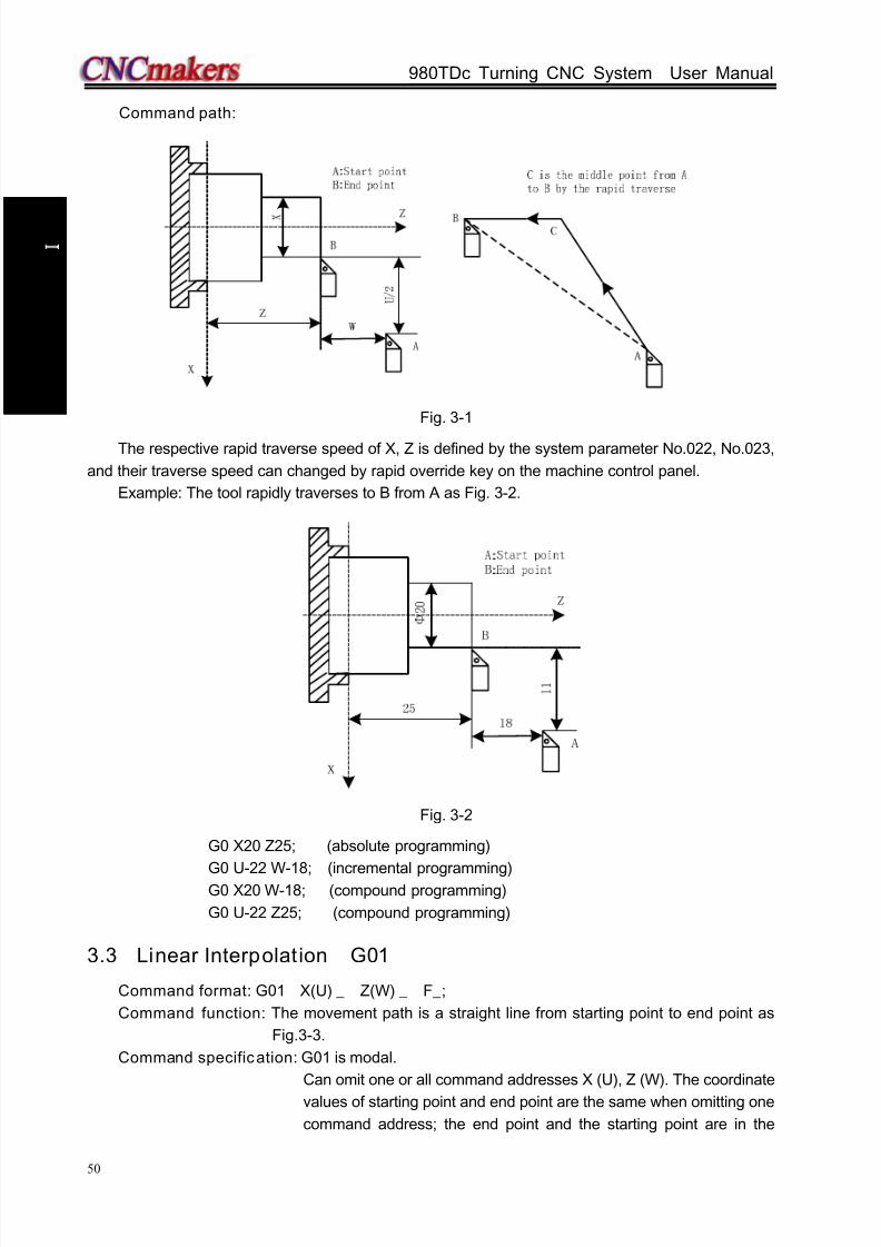
8/17/2019 980TDc CNC Turning Controller User Manual
http://slidepdf.com/reader/full/980tdc-cnc-turning-controller-user-manual 65/461
GSK980TDc Turning CNC System User Manual
50
P r o gr ammi n g
Command path:
Fig. 3-1
The respective rapid traverse speed of X, Z is defined by the system parameter No.022, No.023,
and their traverse speed can changed by rapid override key on the machine control panel.
Example: The tool rapidly traverses to B from A as Fig. 3-2.
Fig. 3-2
G0 X20 Z25; (absolute programming)
G0 U-22 W-18; (incremental programming)G0 X20 W-18; (compound programming)
G0 U-22 Z25; (compound programming)
3.3 Linear Interpolat ion G01
Command format: G01 X(U) _ Z(W) _ F_;
Command function: The movement path is a straight line from starting point to end point as
Fig.3-3.
Command specification: G01 is modal.
Can omit one or all command addresses X (U), Z (W). The coordinate
values of starting point and end point are the same when omitting one
command address; the end point and the starting point are in the

8/17/2019 980TDc CNC Turning Controller User Manual
http://slidepdf.com/reader/full/980tdc-cnc-turning-controller-user-manual 66/461
Chapter 3 G Commands
51
P r o gr ammi n g
same position when all are omitted. X, U, Z, W rang is referred to
Table 1-2 of Section 1.4.1, unit: mm//inch.
F command value is the vector compound speed of X and Z
instantaneous speed and the actual cutting feedrate is the product
between the feedrate override and F command value.
After F command value is executed, it has been reserved unless the
new one is executed. Do not repeat it when the following G
commands adopt functions of F word. Its range is referred to Table
1-2.
Note: In G98, F max. value cannot exceed the value set by the data parameter No.027(upper speed of cutting
feed), otherwise, the system alarms.
Command path:
Fig. 3-3
Example: Cutting path from Φ40 to Φ60 as Fig.3-4:
Fig. 3-4
3.4 Circular Interpolation G02, G03
Command format: G02 R__
X(U) __ Z(W) __
G03 I__ K__
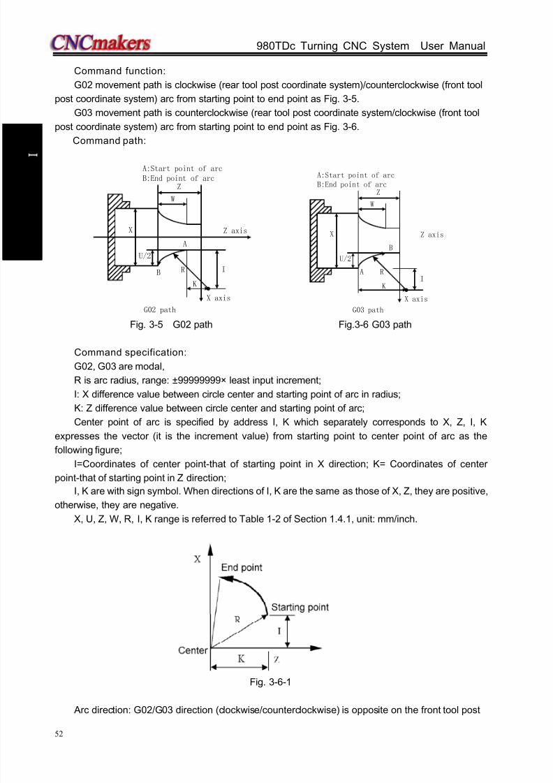
8/17/2019 980TDc CNC Turning Controller User Manual
http://slidepdf.com/reader/full/980tdc-cnc-turning-controller-user-manual 67/461
GSK980TDc Turning CNC System User Manual
52
P r o gr ammi n g
Command function:
G02 movement path is clockwise (rear tool post coordinate system)/counterclockwise (front tool
post coordinate system) arc from starting point to end point as Fig. 3-5.
G03 movement path is counterclockwise (rear tool post coordinate system/clockwise (front tool
post coordinate system) arc from starting point to end point as Fig. 3-6.
Command path:
U/2
X Z axis
X axis
A
B
Z
W
I
A:Start point of arcB:End point of arc
K
R
G02 path
U/2
X Z axis
X axis
A
B
Z
W
IKR
G03 path
A:Start point of arcB:End point of arc
Fig. 3-5 G02 path Fig.3-6 G03 path
Command specification:
G02, G03 are modal,
R is arc radius, range: ±99999999× least input increment;
I: X difference value between circle center and starting point of arc in radius;
K: Z difference value between circle center and starting point of arc;Center point of arc is specified by address I, K which separately corresponds to X, Z, I, K
expresses the vector (it is the increment value) from starting point to center point of arc as the
following figure;
I=Coordinates of center point-that of starting point in X direction; K= Coordinates of center
point-that of starting point in Z direction;
I, K are with sign symbol. When directions of I, K are the same as those of X, Z, they are positive,
otherwise, they are negative.
X, U, Z, W, R, I, K range is referred to Table 1-2 of Section 1.4.1, unit: mm/inch.
Fig. 3-6-1
Arc direction: G02/G03 direction (clockwise/counterclockwise) is opposite on the front tool post

8/17/2019 980TDc CNC Turning Controller User Manual
http://slidepdf.com/reader/full/980tdc-cnc-turning-controller-user-manual 68/461
Chapter 3 G Commands
53
P r o gr ammi n g
coordinate system and the rear one as Fig.3-7:
Fig. 3-7Notes:
When I = 0 or K = 0, they can be omitted; one of I, K or R must be input, otherwise the system
alarms.
R is valid and I, K are invalid when they are input at the same time.
R value must be equal to or more than half distance from starting point to end point, and the
system alarms if the end point is not on the arc defined by R command;
Omit all or one of X(U), Z(W); coordinates of starting point and end point of this axis are the same
when omitting ones, the path is a full circle(360°) in G02/G03 when center point are specified
by I,K; the path is 0(0°) when center point is specified by R.
R should be used for programming. The system executes in R= 22K I + to ensure starting
point and end point of arc path are the specified ones in I, K programming.
When the distance from center point to end point is not equal to R(R= 22K I + ) in I,K
programming, the system automatically adjusts position of center point to ensure starting point
and end point of arc path are the specified ones; when the distance from center point to end point
is more than 2R, and the system alarms.
Arc is less than 360° when R is commanded, the arc is more than 180° when R is negative, and it
is less than or equal to 180° when R is positive.
Example: Arc cutting path from Φ45.25 to Φ63.06 shown in Fig. 3-8.

8/17/2019 980TDc CNC Turning Controller User Manual
http://slidepdf.com/reader/full/980tdc-cnc-turning-controller-user-manual 69/461
GSK980TDc Turning CNC System User Manual
54
P r o gr ammi n g
φ63.060
X
Z
End point
Starting point
Circle center
Fig. 3-8
Compound programming in G02/G03:
Fig. 3-9 Circular programming example
Program: O0001
N001 G0 X40 Z5; (Rapidly traverse)
N002 M03 S200; (Start spindle)
N003 G01 X0 Z0 F900; (Approach workpiece)
N005 G03 U24 W-24 R15; (Cut R15 arc)
N006 G02 X26 Z-31 R5; (Cut R5 arc)
N007 G01 Z-40; (Cut φ26)
N008 X40 Z5; (Return to starting point)
N009 M30; (End of program)
3.5 Three-point Circular Interpolation G05
Command format: G05 X(U)__ Z(W)__ I__ K__ F__

8/17/2019 980TDc CNC Turning Controller User Manual
http://slidepdf.com/reader/full/980tdc-cnc-turning-controller-user-manual 70/461
Chapter 3 G Commands
55
P r o gr ammi n g
Command function: when you do not know positions of the circular center of arc and the radius
but coordinates of three points on the arc, you can use G5 to confirm the
arc direction through the middle position between the initial point and end
point.
Command specification: G05 is modal;
I: incremental coordinate value(X) (radius value, direction) of the middle point where
the circular passes corresponding to the starting point, range: ±99999999× least
input increment;
K: incremental coordinate value(Z, direction) of the middle point where the circular
passes corresponding to the starting point, range: ±99999999× least input
increment; as Fig.3-10:
X, U, Z, W, R, I, K range is referred to Table 1-2 of Section 1.4.1, unit: mm/inch.
Fig. 3-10
Notes:
Middle point: any one point except for the starting point and end point on the arc;
The system alarms when the three points are in the same line;
I=0 when it is omitted, K=0 when it is omitted; the system alarm when they are omitted
simultaneously;
The meanings of I, K I are similar to their displacement values of the circle center coordinates
corresponding to starting point ones in G02/G03;
G05 does not execute the whole circle machining;

8/17/2019 980TDc CNC Turning Controller User Manual
http://slidepdf.com/reader/full/980tdc-cnc-turning-controller-user-manual 71/461
GSK980TDc Turning CNC System User Manual
56
P r o gr ammi n g
Example: (machining semi-circle)
Fig. 3-10-1
3.6 Ellipse Interpolation G6.2, G6.3
Command format: G6.2
X(U)__ Z(W)__ A__ B__ Q__
G6.3
Command function: G6.2 motion path is the CW(rear tool post coordinates)/CCW(front tool
post coordinates) ellipse.
G6.3 motion path is the CCW(rear tool post coordinates)/CW(front tool
post coordinates) ellipse.
Command path:
G6.2 path sketch map G6.3 path sketch map
Explanation:
A: Length of ellipse’s long radius (0<A<= 99999.999mm, no sign )
B: Length of ellipse’s short radius (0<B<= 99999.999mm, no sign )
Q: angle between the long axis and Z coordinate system of ellipse (CCW 0-99999999,
unit: 0.001°)
Program:G0 X10 Z10G05 X30 Z10 I5 K-5
X
Z
Middle point
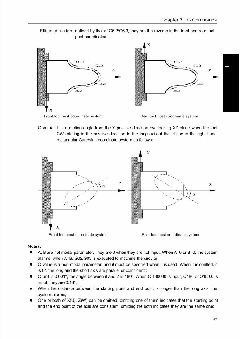
8/17/2019 980TDc CNC Turning Controller User Manual
http://slidepdf.com/reader/full/980tdc-cnc-turning-controller-user-manual 72/461
Chapter 3 G Commands
57
P r o gr ammi n g
Ellipse direction: defined by that of G6.2/G6.3, they are the reverse in the front and rear tool
post coordinates.
Front tool post coordinate system Rear tool post coordinate system
Q value: It is a motion angle from the Y positive direction overlooking XZ plane when the tool
CW rotating in the positive direction to the long axis of the ellipse in the right hand
rectangular Cartesian coordinate system as follows:
Front tool post coordinate system Rear tool post coordinate system
Notes:
A, B are not modal parameter. They are 0 when they are not input. When A=0 or B=0, the system
alarms; when A=B, G02/G03 is executed to machine the circular;
Q value is a non-modal parameter, and it must be specified when it is used. When it is omitted, it
is 0°, the long and the short axis are parallel or coincident ;
Q unit is 0.001°, the angle between it and Z is 180°. When Q 180000 is input, Q180 or Q180.0 is
input, they are 0.18°;
When the distance between the starting point and end point is longer than the long axis, the
system alarms; One or both of X(U), Z(W) can be omitted; omitting one of them indicates that the starting point
and the end point of the axis are consistent; omitting the both indicates they are the same one;
X
Z Z
X
Z
X
Z
X

8/17/2019 980TDc CNC Turning Controller User Manual
http://slidepdf.com/reader/full/980tdc-cnc-turning-controller-user-manual 73/461
GSK980TDc Turning CNC System User Manual
58
P r o gr ammi n g
Only machines the ellipse which is less than 180°(including 180°);
G6.2/G6.3 are used to the compound cycle G70—G73, and their notes are the same those of
G02, G03;
G6.2, G6.3 are used to C tool compensation and their notes are the same those of G02, G03.
Example: machine from Φ43.14 to Φ63.82:
Z
End point
Starting point
Z A:48B:25Q:0
X
Example: machine from Φ43.14 to Φ63.82:
Q:60
Z
X
Z
Starting point
End point
G6.2/G6.3 compound program example :
Fig. 3-11
Program:
G6.2 X63.82 Z-50.0 A48 B25 Q60000;
orG6.2 U20.68 W-50.0 A48 B25 Q60000;
Program:
G6.2 X63.82 Z-50.0 A48 B25 Q0 ;or
G6.2 U20.68 W-50.0 A48 B25 ;

8/17/2019 980TDc CNC Turning Controller User Manual
http://slidepdf.com/reader/full/980tdc-cnc-turning-controller-user-manual 74/461
Chapter 3 G Commands
59
P r o gr ammi n g
Program: O0001
N001 G0 X60 Z5; (rapidly position)
N002 M03 S200; (spindle ON)
N003 G01 X24.24 Z0 F100; (approach the workpiece)
N005 G6.3 X40 W-35 A44 B20; (cutting A44 B20 ellipse block)
N006 G01 X32 Z-60;
N007 Z-79;
N008 G0 X60
N009 Z5; (return to the starting point)
N0010 M30; (end of program)
3.7 Parabola Interpolation G7.2, G7.3
Command format: G7.2
X(U)__ Z(W)__ P__ Q__G7.3
Command function: G7.2 motion path is the CW (rear tool post coordinates)/CCW(front tool
post coordinates) parabola.
G7.3 motion path is the CCW (rear tool post coordinates)/CW(front tool
post coordinates) parabola.
Command path:
G7.2 path sketch map G7.3 path sketch map
Explanation:
G7.2, G7.3 are modal;
P is in the parabola standard equation Y2=2PX, its range: 1~9999999(unit:
0.001mm, without sign);
Q is the angle between the symmetrical axis of parabola and Z, and its range: 0~
99999999 (unit: 0.001°) .Parabola direction: G7.2/7.3 interpolation directions in the front tool post coordinate system and
the rear are reverse.
抛
物
线
起
点
S t ar t i n g
of p ar a b ol a
抛
物
线
终
点
E n d
p oi n t of p ar
a b ol a
S t ar t i n g
p oi n t of
p ar a b ol a
E n d
p oi n t of p ar a b ol a
X X
Z Z

8/17/2019 980TDc CNC Turning Controller User Manual
http://slidepdf.com/reader/full/980tdc-cnc-turning-controller-user-manual 75/461
GSK980TDc Turning CNC System User Manual
60
P r o gr ammi n g
Front tool post coordinate system Rear tool post coordinate system
Q value: it is a motion angle from the Y positive direction overlooking XZ plane when the tool
CW rotating in the positive direction to the long axis of the parabola in the right hand rectangular
Cartesian coordinate system as follows:
Front tool post coordinate system Rear tool post coordinate system
Notes:
P cannot be 0 or omitted, otherwise the system alarms;
P has no sign. If it has the negative sign, its absolute value is executed;
Q can be omitted, at the time, the symmetrical axis of the parabola is parallel with or coincident
with Z ;
The system alarms when the straight line on which the starting point and the end point is parallel
with the symmetrical axis of the parabola;
G7.2, G7.3 can be used to the compound cycle G70~G73, and their notes are the same those
of G02, G03;
G7.2, G7.3 are used to C tool compensation, and their notes are the same those of G02, G03;
Example: when the parabola P=100(the least increment is 0.0001mm), its symmetrical axis is
parallel with Z. Its machining sketch map and programming are as follows:
ZZ
X
X
X
X
Z Z

8/17/2019 980TDc CNC Turning Controller User Manual
http://slidepdf.com/reader/full/980tdc-cnc-turning-controller-user-manual 76/461
Chapter 3 G Commands
61
P r o gr ammi n g
Program:
O0001(O0001)
G00 X120 Z100 T0101 M03 S800;
G00 X10 Z10;
G00 X0;
G01 Z0 F120 M08;
X30;
G7.3 X60 Z-40 P10000 Q0;
G01 X90 Z-60;X110 Z-85;
X120;
M09;
G00 X120 Z100 M05 S0;
M30;
3.8 Plane Selection G17~G19
Command format:
G17……XY planeG18……ZX plane
G19……YZ plane
Command function: use G commands to select the plane of the arc interpolation or the one of
the cutter compensation
Command explanation: G17, G18, G19 are modal, and the plane does not change in the block
without the command.
Notes:
Firstly set the basic axis Y when the system selects G17, G19 plane;
Cannot switch the planes in C tool compensation;
G71~G76,G90,G92,G94 can be used in G18 plane; The plane selection code can be in the same block with G codes in the other groups;
The movement command is not relevant to the plane selection;
X
Z
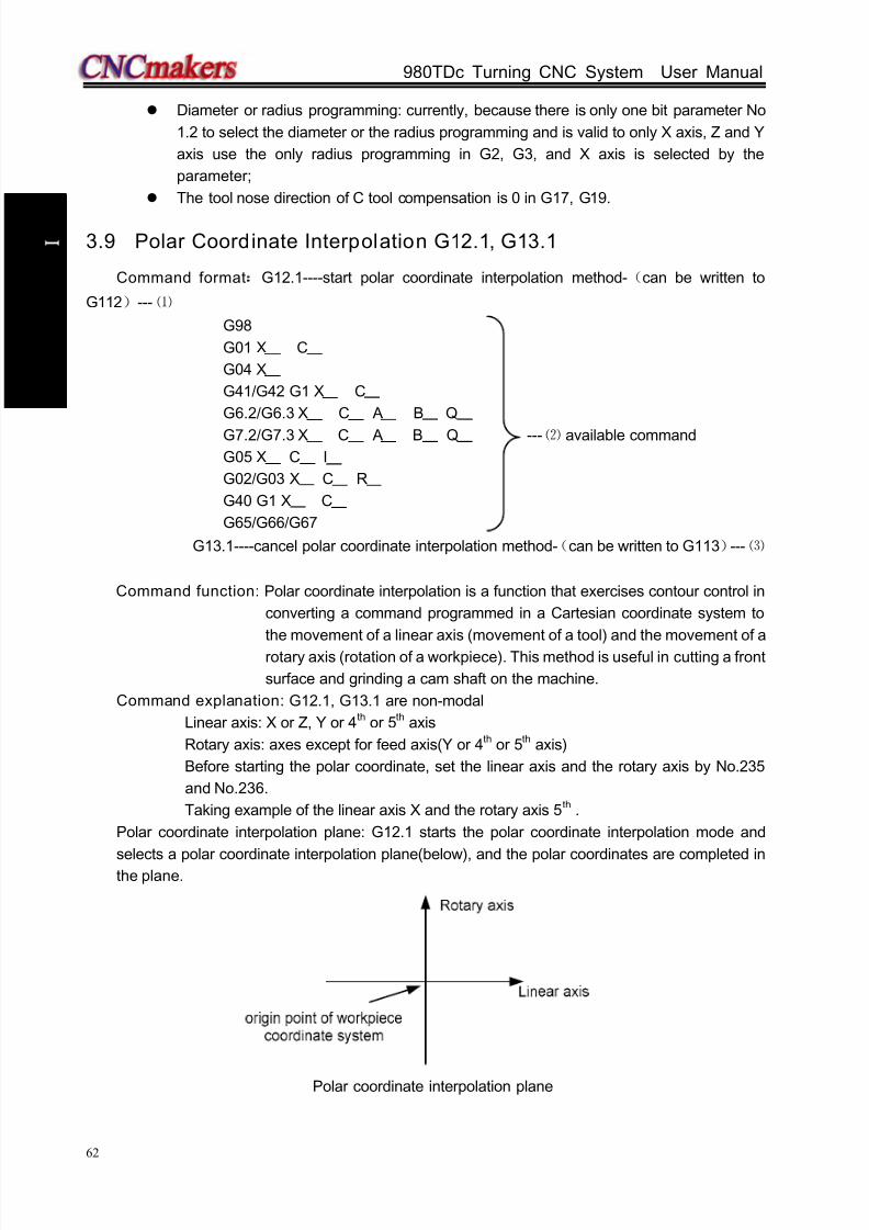
8/17/2019 980TDc CNC Turning Controller User Manual
http://slidepdf.com/reader/full/980tdc-cnc-turning-controller-user-manual 77/461
GSK980TDc Turning CNC System User Manual
62
P r o gr ammi n g
Diameter or radius programming: currently, because there is only one bit parameter No
1.2 to select the diameter or the radius programming and is valid to only X axis, Z and Y
axis use the only radius programming in G2, G3, and X axis is selected by the
parameter;
The tool nose direction of C tool compensation is 0 in G17, G19.
3.9 Polar Coordinate Interpolation G12.1, G13.1
Command format:G12.1----start polar coordinate interpolation method-(can be written to
G112)--- ⑴
G98
G01 X C
G04 X
G41/G42 G1 X C
G6.2/G6.3 X C A B Q
G7.2/G7.3 X C A B Q --- ⑵ available command
G05 X C I
G02/G03 X C R
G40 G1 X C
G65/G66/G67
G13.1----cancel polar coordinate interpolation method-(can be written to G113)--- ⑶
Command function: Polar coordinate interpolation is a function that exercises contour control in
converting a command programmed in a Cartesian coordinate system to
the movement of a linear axis (movement of a tool) and the movement of a
rotary axis (rotation of a workpiece). This method is useful in cutting a front
surface and grinding a cam shaft on the machine.
Command explanation: G12.1, G13.1 are non-modal
Linear axis: X or Z, Y or 4 th or 5th axis
Rotary axis: axes except for feed axis(Y or 4th or 5th axis)
Before starting the polar coordinate, set the linear axis and the rotary axis by No.235
and No.236.
Taking example of the linear axis X and the rotary axis 5 th .
Polar coordinate interpolation plane: G12.1 starts the polar coordinate interpolation mode and
selects a polar coordinate interpolation plane(below), and the polar coordinates are completed inthe plane.
Polar coordinate interpolation plane
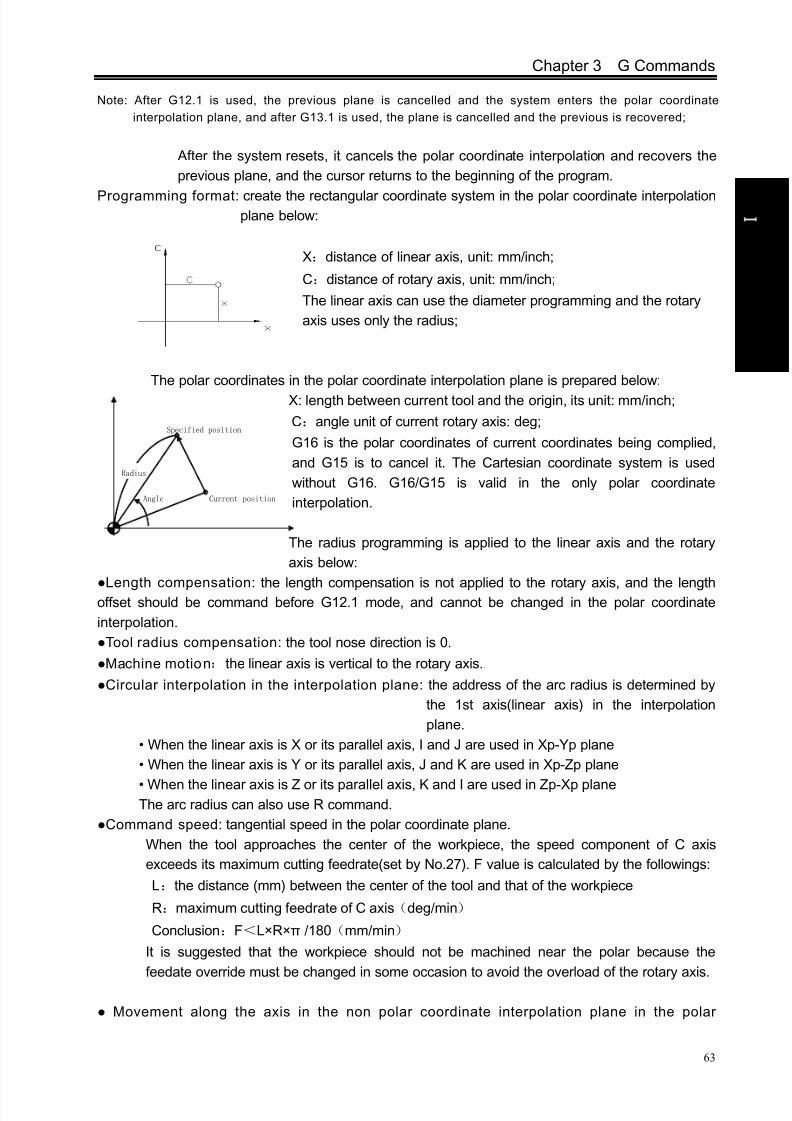
8/17/2019 980TDc CNC Turning Controller User Manual
http://slidepdf.com/reader/full/980tdc-cnc-turning-controller-user-manual 78/461
Chapter 3 G Commands
63
P r o gr ammi n g
Note: After G12.1 is used, the previous plane is cancelled and the system enters the polar coordinate
interpolation plane, and after G13.1 is used, the plane is cancelled and the previous is recovered;
After the system resets, it cancels the polar coordinate interpolation and recovers the
previous plane, and the cursor returns to the beginning of the program.
Programming format: create the rectangular coordinate system in the polar coordinate interpolationplane below:
X:distance of linear axis, unit: mm/inch;
C:distance of rotary axis, unit: mm/inch;
The linear axis can use the diameter programming and the rotary
axis uses only the radius;
The polar coordinates in the polar coordinate interpolation plane is prepared below:
X: length between current tool and the origin, its unit: mm/inch;
C:angle unit of current rotary axis: deg;
G16 is the polar coordinates of current coordinates being complied,
and G15 is to cancel it. The Cartesian coordinate system is used
without G16. G16/G15 is valid in the only polar coordinate
interpolation.
The radius programming is applied to the linear axis and the rotary
axis below:
Length compensation: the length compensation is not applied to the rotary axis, and the lengthoffset should be command before G12.1 mode, and cannot be changed in the polar coordinate
interpolation.
Tool radius compensation: the tool nose direction is 0.
Machine motion:the linear axis is vertical to the rotary axis.
Circular interpolation in the interpolation plane: the address of the arc radius is determined by
the 1st axis(linear axis) in the interpolation
plane.
• When the linear axis is X or its parallel axis, I and J are used in Xp-Yp plane
• When the linear axis is Y or its parallel axis, J and K are used in Xp-Zp plane
• When the linear axis is Z or its parallel axis, K and I are used in Zp-Xp plane The arc radius can also use R command.
Command speed: tangential speed in the polar coordinate plane.
When the tool approaches the center of the workpiece, the speed component of C axis
exceeds its maximum cutting feedrate(set by No.27). F value is calculated by the followings:
L:the distance (mm) between the center of the tool and that of the workpiece
R:maximum cutting feedrate of C axis(deg/min)
Conclusion:F<L×R×π /180(mm/min)
It is suggested that the workpiece should not be machined near the polar because the
feedate override must be changed in some occasion to avoid the overload of the rotary axis.
Movement along the axis in the non polar coordinate interpolation plane in the polar
Specified position
Current positionAngle
Radius
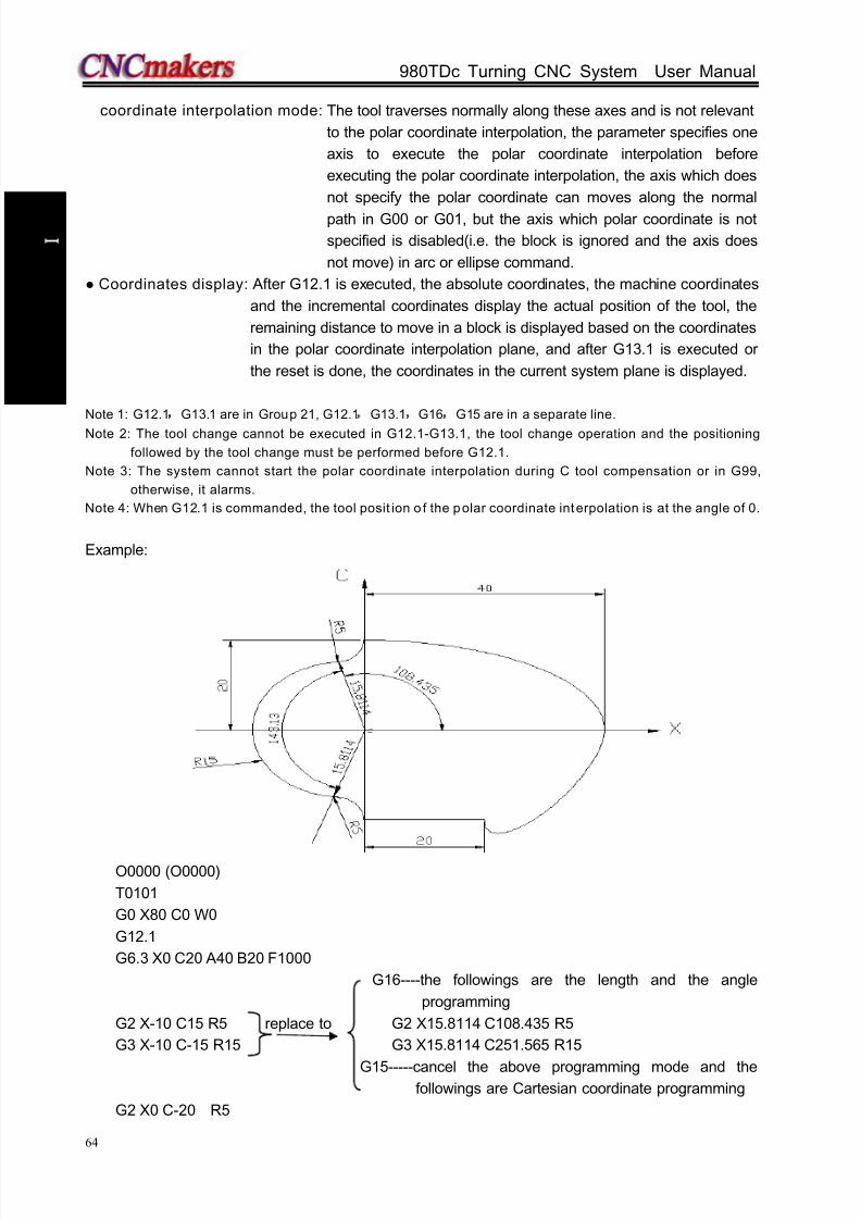
8/17/2019 980TDc CNC Turning Controller User Manual
http://slidepdf.com/reader/full/980tdc-cnc-turning-controller-user-manual 79/461
GSK980TDc Turning CNC System User Manual
64
P r o gr ammi n g
coordinate interpolation mode: The tool traverses normally along these axes and is not relevant
to the polar coordinate interpolation, the parameter specifies one
axis to execute the polar coordinate interpolation before
executing the polar coordinate interpolation, the axis which does
not specify the polar coordinate can moves along the normal
path in G00 or G01, but the axis which polar coordinate is not
specified is disabled(i.e. the block is ignored and the axis does
not move) in arc or ellipse command.
Coordinates display: After G12.1 is executed, the absolute coordinates, the machine coordinates
and the incremental coordinates display the actual position of the tool, the
remaining distance to move in a block is displayed based on the coordinates
in the polar coordinate interpolation plane, and after G13.1 is executed or
the reset is done, the coordinates in the current system plane is displayed.
Note 1: G12.1,G13.1 are in Group 21, G12.1,G13.1,G16,G15 are in a separate line.
Note 2: The tool change cannot be executed in G12.1-G13.1, the tool change operation and the positioning
followed by the tool change must be performed before G12.1.
Note 3: The system cannot start the polar coordinate interpolation during C tool compensation or in G99,
otherwise, it alarms.
Note 4: When G12.1 is commanded, the tool posit ion o f the polar coordinate interpolation is at the angle of 0.
Example:
O0000 (O0000)
T0101
G0 X80 C0 W0
G12.1
G6.3 X0 C20 A40 B20 F1000
G16----the followings are the length and the angle
programming
G2 X-10 C15 R5 replace to G2 X15.8114 C108.435 R5
G3 X-10 C-15 R15 G3 X15.8114 C251.565 R15
G15-----cancel the above programming mode and thefollowings are Cartesian coordinate programming
G2 X0 C-20 R5

8/17/2019 980TDc CNC Turning Controller User Manual
http://slidepdf.com/reader/full/980tdc-cnc-turning-controller-user-manual 80/461
Chapter 3 G Commands
65
P r o gr ammi n g
G1 X40 C-20
G7.3 X80 C0 P10000 Q60000
G13.1
M30
3.10 Cylindrical Interpolation G7.1
Command function:The amount of travel of a rotary axis specified by an angle is once
internally converted to a distance of a linear axis along the outer surface
so that linear interpolation or circular interpolation can be performed with
another axis. After interpolation, such a distance is converted back to
the amount of travel of the rotary axis. The cylindrical interpolation
function allows the side of a cylinder to be developed for
programming(below).
Command format:G07.1 Cc ;(enable/cancel cylindrical interpolation mode)
Cc: the radius of the cylinder ;
Radius ≠0:starts the cylindrical interpolation mode
Radius=0:cancels the cylindrical interpolation mode
(1) A coordinate command from starting the cylindrical interpolation mode to
completing its cancellation is a cylindrical coordinate system;
G07.1 Cxxxx(cylindrical radius value);……starting the cylindrical interpolation
……;
……; ………The coordinate command in the range is a cylindrical
coordinate system
……;
G07.1 C0; ……cancel the cylindrical interpolation
(2) G7.1 is non-modal ;
(3) The cylindrical interpolation mode is cancelled in power-on and reset;
(4) The rotary axis executes a program by an angle, a rolling function of a rotary
axis in the cylindrical interpolation mode will be automatically invalid, and a
programming command value must be more than 3600 when the interpolation
range is more than one circle;
(5) The coordinate value can be absolute or incremental;
(6) The tool nose radius compensation G41, G42 can be executed and their tool
nose directions are 0;
(7) A feedrate specified in the cylindrical interpolation mode is a speed on the
developed cylindrical surface, its unit: mm/min or inch/min;
Spread

8/17/2019 980TDc CNC Turning Controller User Manual
http://slidepdf.com/reader/full/980tdc-cnc-turning-controller-user-manual 81/461
GSK980TDc Turning CNC System User Manual
66
P r o gr ammi n g
Restrictions:
(1) In the cylindrical interpolation mode, the linear G1, the arc G2, G3(arc radius
is specified by R, its unit is mm or inch), ellipse G6.2, G6.3, parabola G7.2,
G7.3 interpolation;
(2) G00 positioning operation cannot be executed in a cylindrical interpolationmode;
(3) Before executing the cylindrical interpolation mode, the tool nose radius
compensation mode which is being executed is cancelled, the tool
compensation is started or completed in a cylindrical interpolation mode;
(4) Miscellaneous function T cannot be used in the cylindrical interpolation mode;
(5) The feedrate in the cylindrical interpolation mode specifies G98(feed per
minute);
(6) G50 setting workpiece coordinate system in the cylindrical interpolation mode
cannot be used; (7) A rotary axis and a linear axis of only current cylinder in the cylindrical
interpolation is specified;
Plane selection: Before a cylindrical interpolation, the plane where the interpolation is should
be selected firstly, one axis in the plane is a linear axis in the cylindrical
interpolation and another is a corresponding linear axis of the developed
rotary axis (below).
Basic coordinate system:
The rotary axis is set to X or its parallel axis in the cylindrical interpolation mode:

8/17/2019 980TDc CNC Turning Controller User Manual
http://slidepdf.com/reader/full/980tdc-cnc-turning-controller-user-manual 82/461
Chapter 3 G Commands
67
P r o gr ammi n g
The rotary axis is set to Y or its parallel axis in the cylindrical interpolation mode:
The rotary axis is set to Z or its parallel axis in the cylindrical interpolation mode:
Relative parameters:
Only rotary axis is specified in the cylindrical interpolation, and it can be a basic axis or an axis
parallel to the basic axis. The axis name of three additional axes are set by NO.225, NO.226,
NO.227 (Y:89, A:65,B:66,C:67), the attribute of an axis is set by NO.230, NO.231,
NO.232(see the following table).
Setting value Meaning
0 It is not three basic axes and their parallel axis
1 X of three basic axes
2 Y of three basic axes
3 Z of three basic axes
5 An axis parallel to X axis
6 An axis parallel to Y axis
7 An axis parallel to Z axis
Example:
No. 224 is set to 5, the cylindrical interpolation is executed in G18 plane, the rotary axis of the
cylindrical interpolation is set to the 5th axis(state parameter P187). The axis name of the 5 th is C(data
parameter No. 225), the axis is an one parallel to X axis (NO.230). The radius of the cylinder is
57.299mm, and the developed cylindrical surface is shown below:

8/17/2019 980TDc CNC Turning Controller User Manual
http://slidepdf.com/reader/full/980tdc-cnc-turning-controller-user-manual 83/461
GSK980TDc Turning CNC System User Manual
68
P r o gr ammi n g
O0071(taking example of the cylindrical interpolation G7.1)
G18;
G98;
G00 X150 Z105 C0;
G01 X114.598 Z105 F200; G07.1 C57.299;
G41 G01 Z120;
N10 G01 C30.0;
N20 G03 Z90 C60 R30;
N30 G01 Z70;
N40 G02 Z60 C70 R10;
N50 G01 C150;
N60 G02 Z70 C190 R75;
N70 G01 Z110 C230;
N80 G03 Z120 C270 R75;
N90 G01 C360;
G40 G01 Z105;
G07.1 C0;
M30;
3.11 Chamfering Function
Chamfering function is to insert one straight line or circular between two contours to make the
tool smoothly transmit from one contour to another one. GSK980TDc uses the linear and circular
chamfering functions.
3.11.1 Linear chamfering
Linear chamfering: insert one straight line in the linear contours, arc contours, linear contour and
arc contour. The command address of linear chamfering is L, behind which data is the length of
chamfering straight line. The linear chamfering must be used in G01, G02 or G03 command.
A. Linear to l inear
Command format: G01 X(U)_ Z(W)_ L_ ;G01 X(U)_ Z(W)_ ;
Command format: G01 X(U)_ Z(W)_ L_ ;

8/17/2019 980TDc CNC Turning Controller User Manual
http://slidepdf.com/reader/full/980tdc-cnc-turning-controller-user-manual 84/461
Chapter 3 G Commands
69
P r o gr ammi n g
Command function: insert one straight line between two linear interpolation blocks.
B. Linear to ci rcular
Command format: G01 X(U)_ Z(W)_ L_;
G02/G03 X(U)_ Z(W)_ R_;
Or
G01 X(U)_ Z(W)_ L_;
G02/G03 X(U)_ Z(W)_ I_ K_;
Command function: insert one straight line between the linear and circular interpolation blocks.
C. Circular to circular
Command format: G02/G03 X(U)_ Z(W)_ R_ L_;
G02/G03 X(U)_ Z(W)_ R_;
Or
G02/G03 X(U)_ Z(W)_ I_ K_ L_;
G02/G03 X(U)_ Z(W)_ I_ K_;
Command function: insert one straight line between two circular interpolation blocks.

8/17/2019 980TDc CNC Turning Controller User Manual
http://slidepdf.com/reader/full/980tdc-cnc-turning-controller-user-manual 85/461
GSK980TDc Turning CNC System User Manual
70
P r o gr ammi n g
D. Circular to linear
Command format: G02/G03 X(U)_ Z(W)_ R_ L_;
G01 X(U)_ Z(W)_;
Or
G02/G03 X(U)_ Z(W)_ I_ K_ L_;
G01 X(U)_ Z(W)_;
Command function: insert one straight line block between circular and linear interpolation
block.
3.11.2 Circu lar chamfering
Circular chamfering: insert one circular between linear contours, circular contours, linear contour
and circular contour, the circular and the contour line are transited by the tangent. The command of
circular chamfering is D, and the data behind the command is the radius of chamfering circular. The
circular chamfering must be used in G01, G02 or G03.
A. Linear to l inear
Command format: G01 X(U)_ Z(W)_ D_;
G01 X(U)_ Z(W)_;
Command function: insert one circular between two straight lines, the inserted circular
block and two straight lines are tangent, the radius is the data behind
the command address D.
Angular bisector
Circular tangent line

8/17/2019 980TDc CNC Turning Controller User Manual
http://slidepdf.com/reader/full/980tdc-cnc-turning-controller-user-manual 86/461
Chapter 3 G Commands
71
P r o gr ammi n g
B. Linear to ci rcular
Command format: G01 X(U)_ Z(W)_ D_;
G02/G03 X(U)_ Z(W)_ R_;
or
G01 X(U)_ Z(W)_ D_;
G02/G03 X(U)_ Z(W)_ I_ K_;
Command function: insert one circular between linear and circular, the inserted circular is
tangent to the linear and the circular, and the radius is the data
behind the command address D.
C. Circular to circular
Command format: G02/G03 X(U)_ Z(W)_ R_ D_;
G02/G03 X(U)_ Z(W)_ R_;
or
G02/G03 X(U)_ Z(W)_ R_ D_;
G02/G03 X(U)_ Z(W)_ I_ K_;or
G02/G03 X(U)_ Z(W)_ I_ K_ D_;
G02/G03 X(U)_ Z(W)_ I_ K_;
or
G02/G03 X(U)_ Z(W)_ I_ K_ D_;
G02/G03 X(U)_ Z(W)_ R_;
Command function: insert one circular between two circular blocks, the inserted circular is
tangent to the two circular blocks, and the radius is the data behind
the command address D.
Tangential point
Tangential point
Tangential point
Tangential point
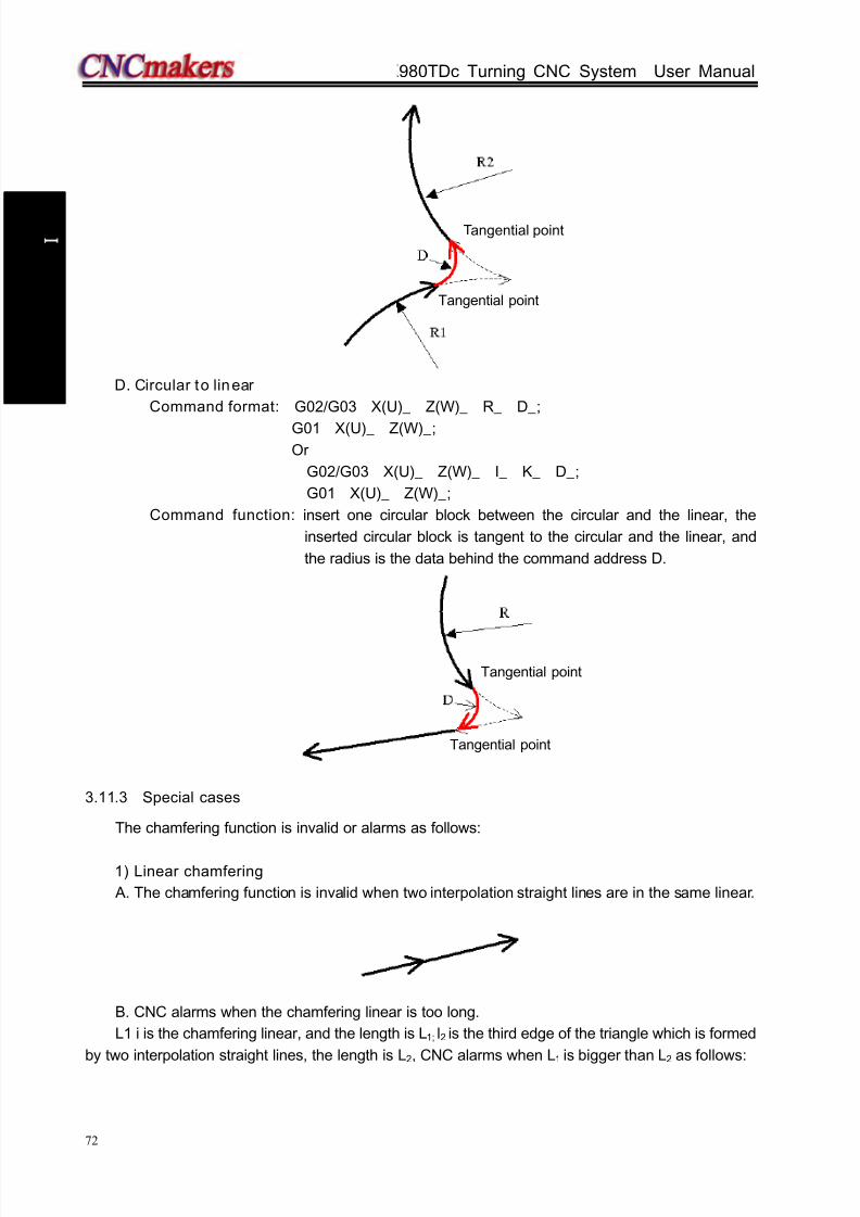
8/17/2019 980TDc CNC Turning Controller User Manual
http://slidepdf.com/reader/full/980tdc-cnc-turning-controller-user-manual 87/461
GSK980TDc Turning CNC System User Manual
72
P r o gr ammi n g
D. Circular to linear
Command format: G02/G03 X(U)_ Z(W)_ R_ D_;
G01 X(U)_ Z(W)_;Or
G02/G03 X(U)_ Z(W)_ I_ K_ D_;
G01 X(U)_ Z(W)_;
Command function: insert one circular block between the circular and the linear, the
inserted circular block is tangent to the circular and the linear, and
the radius is the data behind the command address D.
3.11.3 Special cases
The chamfering function is invalid or alarms as follows:
1) Linear chamfering
A. The chamfering function is invalid when two interpolation straight lines are in the same linear.
B. CNC alarms when the chamfering linear is too long.
L1 i is the chamfering linear, and the length is L1; l2 is the third edge of the triangle which is formed
by two interpolation straight lines, the length is L2, CNC alarms when L1 is bigger than L2 as follows:
Tangential point
Tangential point
Tangential point
Tangential point

8/17/2019 980TDc CNC Turning Controller User Manual
http://slidepdf.com/reader/full/980tdc-cnc-turning-controller-user-manual 88/461
Chapter 3 G Commands
73
P r o gr ammi n g
C. Some linear block is too short
The chamfering linear length is L, CNC alarms when other end of the caculated chamfering
linear is not in the interpolation linear(in the extension line of the interpolation linear).
2) Circular chamfering
A. The circular chamfering function is invalid when two interpolation straight lines are in the same
block.
B. CNC alarms when the chamfering circular radius is too big.
CNC alarms when the chamfering circular radius is D, max. circular radius of the tangential
linear lines is Rmax which is less than D as follows.
C. The circular chamfering function is invalid when the linear and the circular, or the circular and
the linear are tangential.
D. The circular chamfering function is invalid when one circular and another one are tangential.

8/17/2019 980TDc CNC Turning Controller User Manual
http://slidepdf.com/reader/full/980tdc-cnc-turning-controller-user-manual 89/461
GSK980TDc Turning CNC System User Manual
74
P r o gr ammi n g
The circular chamfering function is valid when the circular tangency is as follows:
3.12 Dwell G04
Command format: G04 P__ ; or
G04 X__ ; or
G04 U__ ; or
G04;
Command function: each axis stops the motion, the modal of G commands and the reserved
data, state are not changed, and execute the next block after dwelling the
defined time.
Command specification: G04 is non-modal.
G04 dwell time is defined by the word P__, X__ or U__.Range of -99999999~99999999 (unit: ms).
X, U range is -99999999~99999999 x least input unit (unit: s)
Notes:
The exact stop is executed between the blocks when P, X, U are not input.
The system exactly stop a block when P, X, U are not input or P, X , U specify negative
values.
P is valid when P, X, U are in the same block; X is valid when X, U are in the same block.
When the system executes the feed hold in G04, dwell can be executed after the current
delay time.
3.13 Machine Zero Funct ion
3.13.1 Machine 1st reference poin t G28
Command format: G28 X(U) Z(W) ;
Command function: the tool rapid traverses to the middle point defined by X(U), Z(W) from
starting point and then return to the machine zero.
Command specifications:
G28 is non-modal.
X, Z, Y: absolute coordinates of middle point;U, W, V: Z absolute coordinates of middle point;
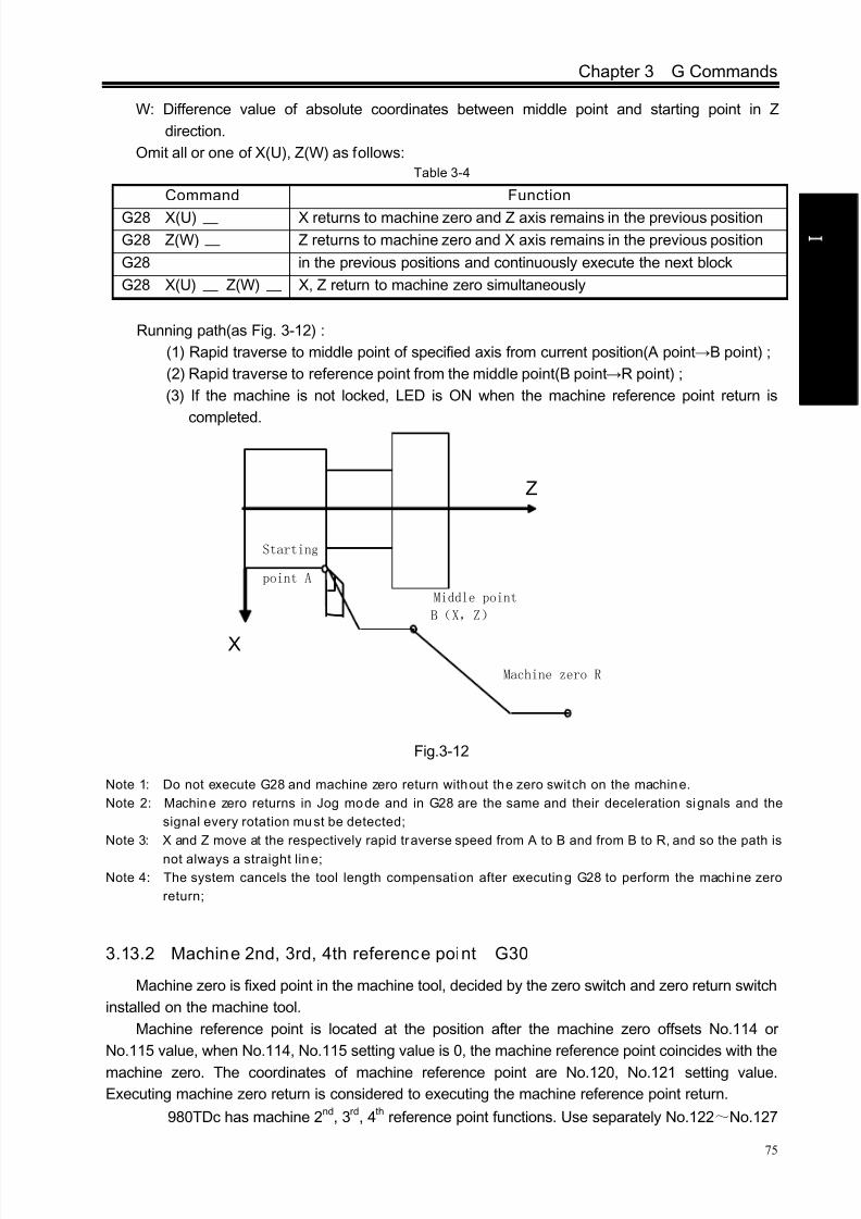
8/17/2019 980TDc CNC Turning Controller User Manual
http://slidepdf.com/reader/full/980tdc-cnc-turning-controller-user-manual 90/461
Chapter 3 G Commands
75
P r o gr ammi n g
W: Difference value of absolute coordinates between middle point and starting point in Z
direction.
Omit all or one of X(U), Z(W) as follows:Table 3-4
Running path(as Fig. 3-12) :
(1) Rapid traverse to middle point of specified axis from current position(A point→B point) ;
(2) Rapid traverse to reference point from the middle point(B point→R point) ;
(3) If the machine is not locked, LED is ON when the machine reference point return is
completed.
Z
X
Middle point
B(X,Z)
Machine zero R
Starting
point A
Fig.3-12
Note 1: Do not execute G28 and machine zero return without the zero switch on the machine.
Note 2: Machine zero returns in Jog mode and in G28 are the same and their deceleration signals and the
signal every rotation must be detected;
Note 3: X and Z move at the respectively rapid traverse speed from A to B and from B to R, and so the path is
not always a straight line;
Note 4: The system cancels the tool length compensation after executing G28 to perform the machine zero
return;
3.13.2 Machine 2nd, 3rd, 4th reference point G30
Machine zero is fixed point in the machine tool, decided by the zero switch and zero return switch
installed on the machine tool.
Machine reference point is located at the position after the machine zero offsets No.114 or
No.115 value, when No.114, No.115 setting value is 0, the machine reference point coincides with the
machine zero. The coordinates of machine reference point are No.120, No.121 setting value.
Executing machine zero return is considered to executing the machine reference point return.
GSK980TDc has machine 2nd, 3rd, 4th reference point functions. Use separately No.122~No.127
Command Function
G28 X(U) X returns to machine zero and Z axis remains in the previous position
G28 Z(W) Z returns to machine zero and X axis remains in the previous position
G28 in the previous positions and continuously execute the next block
G28 X(U) Z(W) X, Z return to machine zero simultaneously
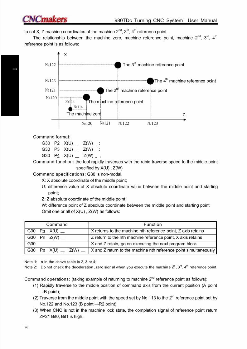
8/17/2019 980TDc CNC Turning Controller User Manual
http://slidepdf.com/reader/full/980tdc-cnc-turning-controller-user-manual 91/461
GSK980TDc Turning CNC System User Manual
76
P r o gr ammi n g
to set X, Z machine coordinates of the machine 2nd, 3rd, 4th reference point.
The relationship between the machine zero, machine reference point, machine 2nd, 3rd, 4th
reference point is as follows:
Command format:
G30 P2 X(U) __ Z(W) __;
G30 P3 X(U) __ Z(W) __;
G30 P4 X(U) Z(W) ;
Command function: the tool rapidly traverses with the rapid traverse speed to the middle point
specified by X(U) , Z(W)
Command specifications: G30 is non-modal.
X: X absolute coordinate of the middle point;
U: difference value of X absolute coordinate value between the middle point and starting
point;
Z: Z absolute coordinate of the middle point;
W: difference point of Z absolute coordinate between the middle point and starting point.
Omit one or all of X(U) , Z(W) as follows:
Command Function
G30 Pn X(U) X returns to the machine nth reference point, Z axis retains
G30 Pn Z(W) Z return to the nth machine reference point, X axis retains
G30 X and Z retain, go on executing the next program blockG30 Pn X(U) Z(W) X and Z return to the machine nth reference point simultaneously
Note 1: n in the above table is 2, 3 or 4;
Note 2: Do not check the deceleration , zero signal when you execute the machine 2nd
, 3rd
, 4th
reference point.
Command operations: (taking example of returning to machine 2nd reference point as follows):
(1) Rapidly traverse to the middle position of command axis from the current position (A point
→B point);
(2) Traverse from the middle point with the speed set by No.113 to the 2nd reference point set by
No.122 and No.123 (B point →R2 point);(3) When CNC is not in the machine lock state, the completion signal of reference point return
ZP21 Bit0, Bit1 is high.
The machine zero
The 3r machine reference point
The 4 machine reference point
The 2n machine reference point
Z
X
120
120
121 122 123
121
123
122
114
114 The machine reference point

8/17/2019 980TDc CNC Turning Controller User Manual
http://slidepdf.com/reader/full/980tdc-cnc-turning-controller-user-manual 92/461
Chapter 3 G Commands
77
P r o gr ammi n g
Starting point A
Z
X
Middle pointB(X,Z)
The machine 2nd reference point R2
Note 1: Execute the machine 2nd
, 3rd
, 4th
reference point return after you manually execute the machine
reference point return or G28 (machine reference point return).Note 2: A→B and B0→R2, two axes separately traverse, and so their trails are linear or not.
Note 3: CNC cancels the tool leng th compensation after you execute G30 to return 2nd, 3rd, and 4th
reference point.
Note 4: Must not execute G30 (machine 2nd, 3rd, 4th reference point return) when the zero switch is not
installed on the machine.
Note 5: Do not set the workpiece coordinate system when you execute the 2nd, 3rd, and the machine 4th
reference point return.
3.14 Skip Interpolation G31
Command format: G31 X(U)_ Z(W)_ F_;
Command function: in executing the command, when the outside skip signal (X3.5) is input, the
system stops the command to execute the next block. The function is used
to the dynamic measure (such as milling machine), toolsetting measure
and so on of workpiece measure.
Command explanations: non-modal G command (00 group);
Its address format is same that of G01;
Cancel the tool nose radius compensation before using it;
Feedrate should not be set to too big to get the precise stop position;
a. following block execution after skip:
1. The next block of G31 is the incremental coordinate programming shown in Fig. 3-13:

8/17/2019 980TDc CNC Turning Controller User Manual
http://slidepdf.com/reader/full/980tdc-cnc-turning-controller-user-manual 93/461
GSK980TDc Turning CNC System User Manual
78
P r o gr ammi n g
Fig. 3-13
2. The next block of G31 is the absolute coordinate programming of one axis as Fig. 3-14:
Fig. 3-14
3. The next block of G31 is the absolute coordinate programming of two axes shown in Fig. 3-15:
Program: G31 Z200 F100
G01 X100 Z300
100
(100,300)
Input skipsignal here
Actual motion
Motion without skip signal
200 300
100
Z
X
Fig. 3-15
8/17/2019 980TDc CNC Turning Controller User Manual
http://slidepdf.com/reader/full/980tdc-cnc-turning-controller-user-manual 94/461
Chapter 3 G Commands
79
P r o gr ammi n g
b. Signals relevant to G31
Skip signal:
SKIP: X3.5
Type: input signal
Function: X3.5 ends the skip cutting. I.e. in a block containing G31, the skip signal becoming the
absolute coordinate position of “1” is to be stored in the macro variable (#997~#999
separately corresponds to X, Z, Y)
Operation: when the skip signal becomes “0”, CNC executes as follows:
When the block is executing G31, CNC stores the current absolute coordinates of
each axis. CNC stops G31 to execute the next block, the skip signal detects its state
instead of its RISING EDGE. So when the skip signal is “1”, it meets the skip
conditions.
Note: If G31 is not used, X3.5 inpu t interface is used to the common input in terface. The skip signal is valid ,
CNC immediately stops the feed axis (without acceleration/deceleration execution), and G31 feedrate
should be as low as possible below 1000 mm/min to get the precise stop position.
c. Parameters relevant to G31: refer to Ⅲ INSTALLATION & CONNECTION, Section 3.2.15.
3.15 Automatic Tool Offset G36, G37
Command format: G36 X__;
G37 Z__;
Command function: when the command is executed to make the tool move to the measured
position, the CNC automatically measures the difference between the current
actual coordinates and the command coordinates to be the tool offset value.The function is used to the automatic toolsetting.
Explanations: X absolute coordinate(only used to G36), Z absolute coordinate (only used to G37);
Non-modal G command (00 group);
Cancel the tool nose radius compensation before using it;
Only use the absolute programming;
Define the workpiece coordinate system before using the command;
Specify the tool number and tool compensation number before using the command;
a. Signals relevant to G36, G37 automatic tool offset:
Measured position arrival signal:
XAE(X3.6) ――――corresponding to G36ZAE(X3.7) ――――corresponding to G37
Type: input signal
Function: when the position measured by the program command is different from that where the
tool actually reaches (i.e. at the time, the measured position arrival signal becomes
“1”), the difference of the coordinates is added to the current tool compensation value
to update the compensation value. When G36X_(or G37Z_) is executed, the tool firstly
rapidly traverses to the position measured by the command, and decelerates and
temporarily stop the position before the measured position, and then, reaches to the
measured position at the speed set by No.141. When the measured position arrivalsignal corresponding to G command becomes “1”, and the tool is in the measured
position range ±ε, CNC updates the offset compensation value and ends the block.

8/17/2019 980TDc CNC Turning Controller User Manual
http://slidepdf.com/reader/full/980tdc-cnc-turning-controller-user-manual 95/461
GSK980TDc Turning CNC System User Manual
80
P r o gr ammi n g
When the measured position arrival signal does not become “1”, and after the tool
reaches the measured position distance ε, the CNC alarms, ends the block and does
not update the offset compensation value.
b. Parameters relevant to G36, G37: refer to INSTALLATION, Section 3.2.16.
c. G36, G37 automatic tool offset command use
Feedrate and alarm
From the initial position to the measured position specified by Xa or Za in G36 or G37, the tool
rapidly traverses to A zone and stops at T point (Xa– γx or Za– γz) , and then traverses to B, C and D
at the feedrate set by No.141. The system alarms when the tool traverses in B zone and the
measured point arrival signal of the end point is set to. CNC alarms when the tool stops at V point.
Example:
G50 X760 Z1100; create the workpiece coordinate system
T0101; define No. 1 tool and execute its tool compensation
G36 X200; traverse to X toolsetting point ( X toolsetting point coordinate: 200)
T0101; execute X tool compensation again
G00 X204; retract a little
G37 Z800; traverse to Z toolsetting point ( Z toolsetting point coordinate: 800)
T0101; execute Z tool compensation again and the toolsetting is completed
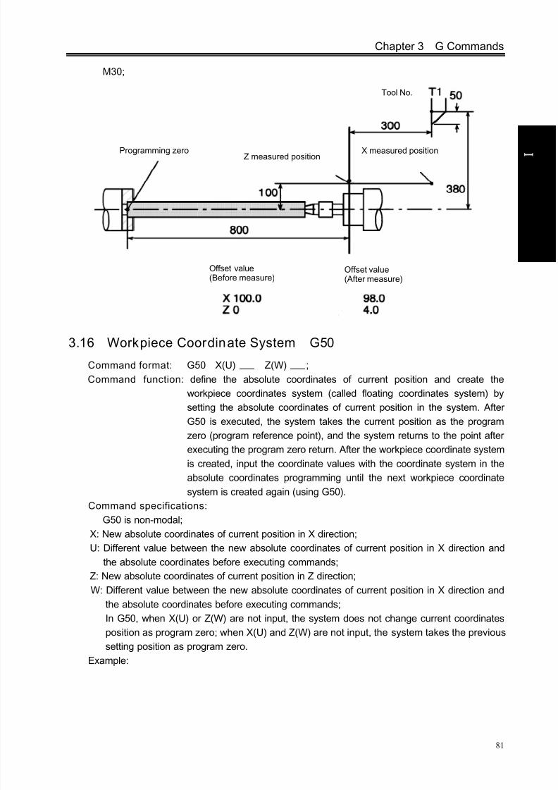
8/17/2019 980TDc CNC Turning Controller User Manual
http://slidepdf.com/reader/full/980tdc-cnc-turning-controller-user-manual 96/461
Chapter 3 G Commands
81
P r o gr ammi n g
M30;
3.16 Workpiece Coordinate System G50
Command format: G50 X(U) Z(W) ;
Command function: define the absolute coordinates of current position and create the
workpiece coordinates system (called floating coordinates system) by
setting the absolute coordinates of current position in the system. After
G50 is executed, the system takes the current position as the program
zero (program reference point), and the system returns to the point after
executing the program zero return. After the workpiece coordinate system
is created, input the coordinate values with the coordinate system in the
absolute coordinates programming until the next workpiece coordinate
system is created again (using G50).
Command specifications:
G50 is non-modal;
X: New absolute coordinates of current position in X direction;
U: Different value between the new absolute coordinates of current position in X direction andthe absolute coordinates before executing commands;
Z: New absolute coordinates of current position in Z direction;
W: Different value between the new absolute coordinates of current position in X direction and
the absolute coordinates before executing commands;
In G50, when X(U) or Z(W) are not input, the system does not change current coordinates
position as program zero; when X(U) and Z(W) are not input, the system takes the previous
setting position as program zero.
Example:
Programming zeroZ measured position
Offset value
(Before measure)
Offset value
(After measure)
X measured position
Tool No.
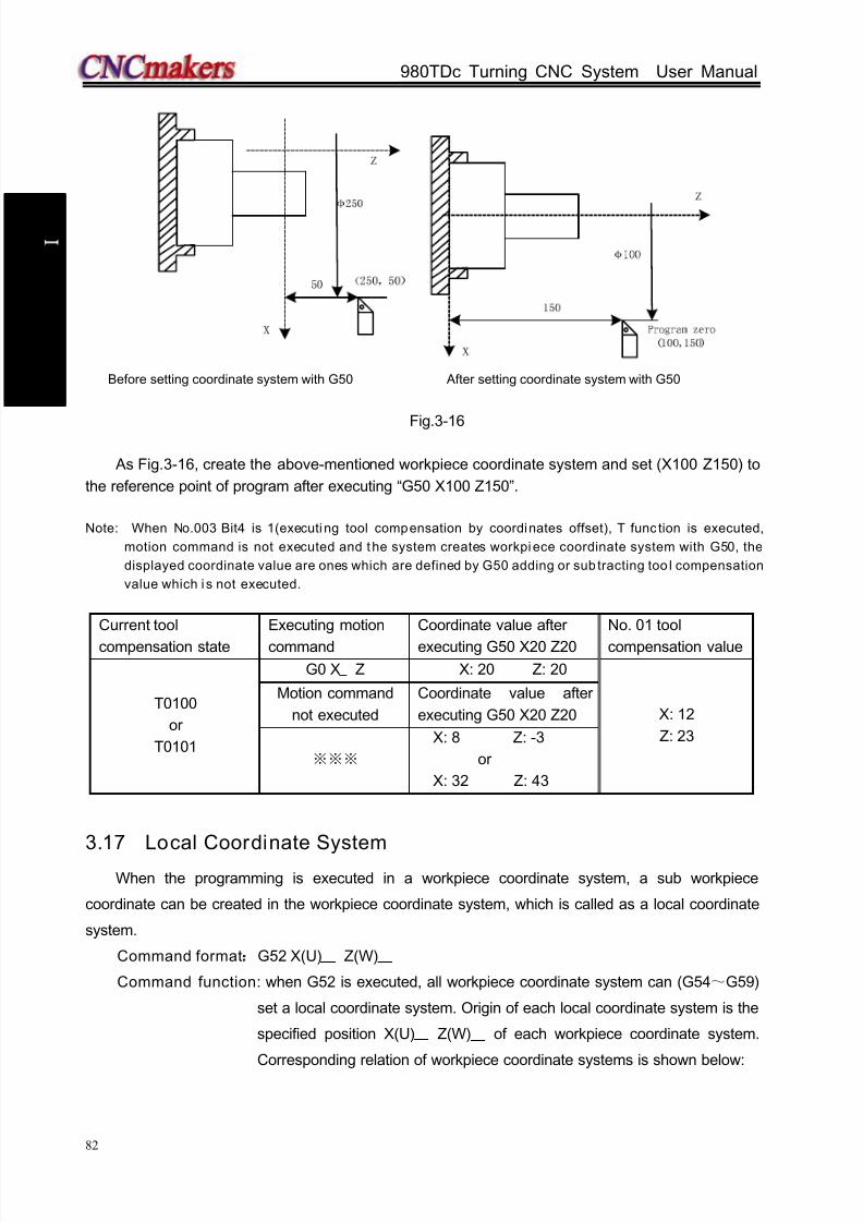
8/17/2019 980TDc CNC Turning Controller User Manual
http://slidepdf.com/reader/full/980tdc-cnc-turning-controller-user-manual 97/461
GSK980TDc Turning CNC System User Manual
82
P r o gr ammi n g
Before setting coordinate system with G50 After setting coordinate system with G50
Fig.3-16
As Fig.3-16, create the above-mentioned workpiece coordinate system and set (X100 Z150) to
the reference point of program after executing “G50 X100 Z150”.
Note: When No.003 Bit4 is 1(executing tool compensation by coordinates offset), T func tion is executed,
motion command is not executed and the system creates workpiece coordinate system with G50, the
displayed coordinate value are ones which are defined by G50 adding or sub tracting too l compensation
value which i s not executed.
Current tool
compensation state
Executing motion
command
Coordinate value after
executing G50 X20 Z20
No. 01 tool
compensation value
T0100
or
T0101
G0 X Z X: 20 Z: 20
X: 12
Z: 23
Motion command
not executed
Coordinate value after
executing G50 X20 Z20
※※※
X: 8 Z: -3
or
X: 32 Z: 43
3.17 Local Coordinate System
When the programming is executed in a workpiece coordinate system, a sub workpiece
coordinate can be created in the workpiece coordinate system, which is called as a local coordinate
system.
Command format:G52 X(U) Z(W)
Command function: when G52 is executed, all workpiece coordinate system can (G54~G59)
set a local coordinate system. Origin of each local coordinate system is the
specified position X(U) Z(W) of each workpiece coordinate system.
Corresponding relation of workpiece coordinate systems is shown below:

8/17/2019 980TDc CNC Turning Controller User Manual
http://slidepdf.com/reader/full/980tdc-cnc-turning-controller-user-manual 98/461
Chapter 3 G Commands
83
P r o gr ammi n g
Explanation: G52 is in Group 00, and is simple. X(U) Z(W) is the position of origin of the
specified local coordinate system in the current workpiece coordinate system.
Results in absolute or incremental execution are the same.
Notes:
Setting of local coordinate system does not change a workpiece coordinate system and a machine
coordinate system.
Temporarily cancel tool nose radius compensation when G52 is executed.
After G52 is specified, the local coordinate system does not remain valid until the next G52 is
specified. G52 does not perform movement when it is specified.
When a local coordinate system is cancelled, its zero and that of workpiece coordinate system are
consistent, i.e., command G52 X0 Z0 or G52 U0 W0.
When G50 sets a workpiece coordinate system, local coordinate systems of all workpiece coordinate
systems which axes are specified are cancelled. The local coordinate systems which coordinate axes
are not specified are not cancelled when not all axes’ coordinate value are specified.
Whether the local coordinate system is cancelled is determined by a parameter when reset, machine
zero return or end of program.
X
Z
Z′
X′
Local coordinate system
G54 workpiece coordinate system
G52 X Z
X
Z
Z′
X′
Local coordinate system
G59 workpiece coordinate system
G52 X Z
G55G56
G57
G58
Origin of coordinate system
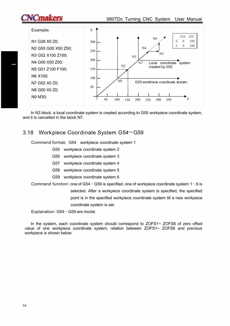
8/17/2019 980TDc CNC Turning Controller User Manual
http://slidepdf.com/reader/full/980tdc-cnc-turning-controller-user-manual 99/461
GSK980TDc Turning CNC System User Manual
84
P r o gr ammi n g
Example:
N1 G28 X0 Z0;
N2 G55 G00 X50 Z50;
N3 G52 X100 Z100;N4 G00 X50 Z50;
N5 G01 Z100 F100;
N6 X100;
N7 G52 X0 Z0;
N8 G00 X0 Z0;
N9 M30;
In N3 block, a local coordinate system is created according to G55 workpiece coordinate system,and it is cancelled in the block N7.
3.18 Workpiece Coordinate System G54~G59
Command format:G54 workpiece coordinate system 1
G55 workpiece coordinate system 2
G56 workpiece coordinate system 3
G57 workpiece coordinate system 4
G58 workpiece coordinate system 5G59 workpiece coordinate system 6
Command function: one of G54~G59 is specified, one of workpiece coordinate system 1~6 is
selected. After a workpiece coordinate system is specified, the specified
point is in the specified workpiece coordinate system till a new workpiece
coordinate system is set.
Explanation: G54~G59 are modal.
In the system, each coordinate system should correspond to ZOFS1~ ZOFS6 of zero offset
value of one workpiece coordinate system, relation between ZOFS1~ ZOFS6 and previousworkpiece is shown below:
50 100 150 200 250 300 350
50
100
150
200
250
300
N2
N3
N4
N5
N6
X
Z
G55 work iece coordinate s stem
Local coordinate systemcreated by G52
N7
N8
G54 G55
X 0 100
Z 0 100

8/17/2019 980TDc CNC Turning Controller User Manual
http://slidepdf.com/reader/full/980tdc-cnc-turning-controller-user-manual 100/461
Chapter 3 G Commands
85
P r o gr ammi n g
When
11.7( APRS)is set to 1, an absolute coordinate system is set after machine zero return,and then EXOFS and ZOFSn setting values are offset. Current workpiece coordinate setting afterzero return is shown: new workpiece coordinates=current absolute coordinates-(ZOFSn + EXOFS).
G54~G59 workpiece coordinate system switch
Specifying G54~G59 can switch 6 workpiece coordinate systems to make the system work in
different workpiece systems. Absolute coordinate variation of current position is the origin offset value
between the new workpiece coordinate system and the old. Namely:new absolute coordinates
=current absolute coordinates -(ZOFS new – ZOFS old)
Example:
Example 1: Absolute coordinates after zero return is(0,0);EXOF=(0,0) ; ZOFS1=(-10,-10);
Absolute coordinate values after zero return in G54: 0 - (-10 + 0) = 10;
Example 2:
Absolute coordinate values after zero return:(20,20);EXOF=(5,5) ; ZOFS2=(10, 10);
Absolute coordinate values after zero return in G55: 20 - (10 + 5) = 5;
Example 3:
Current absolute coordinates (10,10); EXOF=(5,5) ; ZOFS1=(-10,-10); ZOFS2 =
(-30,-30); absolute coordinate values from G54 to G55: 10-(-30-(-10))= 30
EXOFS:external workpiece coordinate zero(it is added to zero offset value of each workpiececoordinate system, its value is a part of tool compensation->setting in the workpiece coordinatesystem)
ZOFSn:zero offset value of each workpiece coordinate system ZOFS1~ZOFS6(its value is a
part of tool compensation->setting in the workpiece coordinate system)
Workpiece
coordinatesystem 1 G54
Workpiececoordinatesystem 2 G55
Workpiececoordinatesystem 3 G56
Workpiececoordinatesystem 4 G57
Workpiececoordinatesystem 5G58
Workpiececoordinatesystem 6 G59
EXOFS
ZOFS1
ZOFS2
ZOFS3ZOFS4
ZOFS5
ZOFS6
Absolute coordinate at machine zero

8/17/2019 980TDc CNC Turning Controller User Manual
http://slidepdf.com/reader/full/980tdc-cnc-turning-controller-user-manual 101/461
GSK980TDc Turning CNC System User Manual
86
P r o gr ammi n g
Notes:
When 11.7( APRS)is set to 0, the absolute coordinate system after machine zero return is
not set, and the EXOF and ZOFSn offset cannot be executed because the workpiece
coordinate system is not set again.
Modification setting of EXOFS and ZOFSn are valid only in non-run state, namely, setting
values of each workpiece coordinate system cannot be modified when a program is running.
The workpiece coordinate system offset is immediately valid after values of EXOFS and
ZOFSn are modified.
Whether the incremental coordinates include offset values of the coordinate system is set
by05.1(PPD).
In tool nose radius compensation mode, compensation is cancelled temporarily in G54~G59,
and is recovered in the next movement command.
When G54~G59 and G50 are in the same block, G54~G59 are invalid, but G50 is valid.
When G50 sets the coordinate system, origin of the current workpiece system is modified. So,
there is an offset value of origins between a new coordinate system set by G50 and
previously current coordinate system. The offset value should be added to offset values of
origins of all workpiece coordinate systems, i.e. all workpiece coordinate systems move the
same values, which are shown below:
Offset value A are all workpiece coordinate systems, which are shown below:
8/17/2019 980TDc CNC Turning Controller User Manual
http://slidepdf.com/reader/full/980tdc-cnc-turning-controller-user-manual 102/461
Chapter 3 G Commands
87
P r o gr ammi n g
3.19 Fixed Cycle Command
To simplify programming, the system defines G command of single machining cycle with one
block to complete the rapid traverse to position, linear/thread cutting and rapid traverse to return to
the starting point:
G90: axial cutting cycle;G92: thread cutting cycle;
G94: radial cutting cycle;
G92 will be introduced in section Thread Function.
3.19.1 Axial cut ting cycle G90
Command format: G90 X(U) __ Z(W) __ F__; (cylinder cutting)
G90 X(U) __ Z(W) __ R__ F__; (taper cutting)
Command function: From starting point, the cutting cycle of cylindrical surface or taper surface
is completed by radial feeding(X) and axial (Z or X and Z) cutting.
Command specifications:
G90 is modal;
Starting point of cutting: starting position of linear interpolation(cutting feed)
End point of cutting: end position of linear interpolation(cutting feed)
X: X absolute coordinates of cutting end point
U: different value of X absolute coordinate between end point and starting point of cutting
Z: different value of Z absolute coordinate between end point and starting point of cutting
W: different value of Z absolute coordinate between end point and starting point of cutting
R: different value (radius value) of X absolute coordinates between end point and start point of
cutting. When the signs of R is not the same that of U, R≤U/2; when R=0 or the input is
default, the cylinder cutting is executed as Fig.3-17, otherwise, the cone cutting is executed
as Fig. 3-18; unit: mm.
Ranges of X, U, Z, W,R are referred to Table 1-2 of Section 1.4.1, unit: mm/inch.
Cycle process:
① X rapidly traverses from starting point to cutting starting point;
② Cutting feed (linear interpolation) from the cutting starting point to cutting end point;
③ X executes the tool retraction at feedrate (opposite direction to the above-mentioned ①), and
return to the position which the absolute coordinates and the starting point are the same;
④ Z rapidly traverses to return to the starting point and the cycle is completed.

8/17/2019 980TDc CNC Turning Controller User Manual
http://slidepdf.com/reader/full/980tdc-cnc-turning-controller-user-manual 103/461
GSK980TDc Turning CNC System User Manual
88
P r o gr ammi n g
Fig. 3-17
Fig. 3-18
Cutting path: Relative position between cutting end point and starting point with U, W, R, and tool path
of U, W, R with different signs are shown in Fig. 3-19:
1) U>0,W<0,R>0 2) U<0,W<0,R<0
W
U/2 ③ ①
②
④ R
WZ
X
Z
X
①
②
③
④
U/ 2
R

8/17/2019 980TDc CNC Turning Controller User Manual
http://slidepdf.com/reader/full/980tdc-cnc-turning-controller-user-manual 104/461
Chapter 3 G Commands
89
P r o gr ammi n g
3) U>0,W>0,R<0 ,R≤U/2 4) U<0,W>0,R>0,R≤U/2
④
R
W
U/2③
②
①
Z
X
R
W
U/2
②
①
④
③
Z
X
Fig. 3-19
Example: Fig. 3-20, rod Φ125×110
Fig. 3-20
Program : O0002;
M3 S300 G0 X130 Z3;
G90 X120 Z-110 F200; (A→D, cut Φ120)
X110 Z-30;X100;
X90;
X80;
X70;
X60;
G0 X120 Z-30;
G90 X120 Z-44 R-7.5 F150;
Z-56 R-15
Z-68 R-22.5
Z-80 R-30M30;
( A→B,6 times cutting cycle Φ60, increment of 10mm)
(B→C,4 times taper cutting)
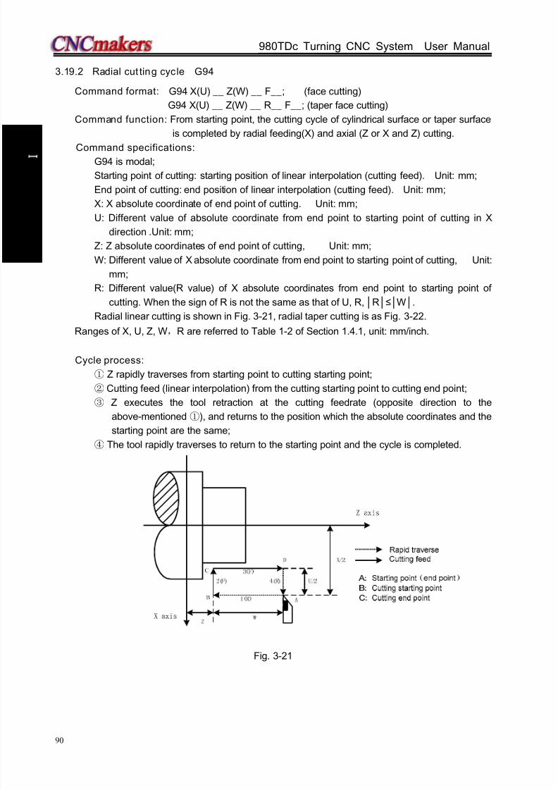
8/17/2019 980TDc CNC Turning Controller User Manual
http://slidepdf.com/reader/full/980tdc-cnc-turning-controller-user-manual 105/461
GSK980TDc Turning CNC System User Manual
90
P r o gr ammi n g
3.19.2 Radial cut ting cycle G94
Command format: G94 X(U) __ Z(W) __ F__; (face cutting)
G94 X(U) __ Z(W) __ R__ F__; (taper face cutting)
Command function: From starting point, the cutting cycle of cylindrical surface or taper surface
is completed by radial feeding(X) and axial (Z or X and Z) cutting. Command specifications:
G94 is modal;
Starting point of cutting: starting position of linear interpolation (cutting feed). Unit: mm;
End point of cutting: end position of linear interpolation (cutting feed). Unit: mm;
X: X absolute coordinate of end point of cutting. Unit: mm;
U: Different value of absolute coordinate from end point to starting point of cutting in X
direction .Unit: mm;
Z: Z absolute coordinates of end point of cutting, Unit: mm;
W: Different value of X absolute coordinate from end point to starting point of cutting, Unit:
mm;R: Different value(R value) of X absolute coordinates from end point to starting point of
cutting. When the sign of R is not the same as that of U, R, R≤W.
Radial linear cutting is shown in Fig. 3-21, radial taper cutting is as Fig. 3-22.
Ranges of X, U, Z, W,R are referred to Table 1-2 of Section 1.4.1, unit: mm/inch.
Cycle process:
① Z rapidly traverses from starting point to cutting starting point;
② Cutting feed (linear interpolation) from the cutting starting point to cutting end point;
③ Z executes the tool retraction at the cutting feedrate (opposite direction to the
above-mentioned ①), and returns to the position which the absolute coordinates and thestarting point are the same;
④ The tool rapidly traverses to return to the starting point and the cycle is completed.
Fig. 3-21

8/17/2019 980TDc CNC Turning Controller User Manual
http://slidepdf.com/reader/full/980tdc-cnc-turning-controller-user-manual 106/461
Chapter 3 G Commands
91
P r o gr ammi n g
Fig. 3-22
Cutting path: Relative position between cutting end point and starting point with U, W is shown in
Fig.3-23:
1) U>0 W<0 R<0 2) U<0 W<0 R<0
R
W
U/2
①
②
③
④
R
W
U/2
①
②
③
④
Z
X
Z
X
(3)U>0 W>0 R<0 (R≤W) 4)U<0 W>0 R<0 (R≤W)
R
U/2
①
②
③
④
R
U/2
W
W
Z
X
Z
X
①
②
③
④
Fig. 3-23
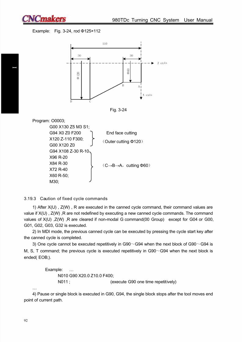
8/17/2019 980TDc CNC Turning Controller User Manual
http://slidepdf.com/reader/full/980tdc-cnc-turning-controller-user-manual 107/461
GSK980TDc Turning CNC System User Manual
92
P r o gr ammi n g
Example: Fig. 3-24, rod Φ125×112
Fig. 3-24
Program: O0003;G00 X130 Z5 M3 S1;
G94 X0 Z0 F200 End face cutting
X120 Z-110 F300;
G00 X120 Z0
G94 X108 Z-30 R-10
X96 R-20
X84 R-30
X72 R-40
X60 R-50;
M30;
3.19.3 Caution of fixed cycle commands
1) After X(U) , Z(W) , R are executed in the canned cycle command, their command values are
value if X(U) , Z(W) ,R are not redefined by executing a new canned cycle commands. The command
values of X(U) ,Z(W) ,R are cleared if non-modal G command(00 Group) except for G04 or G00,
G01, G02, G03, G32 is executed.
2) In MDI mode, the previous canned cycle can be executed by pressing the cycle start key after
the canned cycle is completed.3) One cycle cannot be executed repetitively in G90~G94 when the next block of G90~G94 is
M, S, T command; the previous cycle is executed repetitively in G90~G94 when the next block is
ended( EOB;).
Example: …
N010 G90 X20.0 Z10.0 F400;
N011 ; (execute G90 one time repetitively)
…
4) Pause or single block is executed in G90, G94, the single block stops after the tool moves end
point of current path.
(Outer cutting Φ120)
(C→B→ A,cuttingΦ60)

8/17/2019 980TDc CNC Turning Controller User Manual
http://slidepdf.com/reader/full/980tdc-cnc-turning-controller-user-manual 108/461
Chapter 3 G Commands
93
P r o gr ammi n g
3.20 Multiple Cycle Commands
Multiple cycle commands of the system includes axial roughing cycle G71, radial roughing cycle
G72, closed cutting cycle G73, finishing cycle G70, axial grooving multiple cycle G74, axial grooving
multiple cycle G75 and multiple thread cutting cycle G76. When the system executes these
commands, it automatically counts the cutting times and the cutting path according to theprogrammed path, travels of tool infeed and tool retraction, executes multiple machining cycle (tool
infeed → cutting→retract tool→tool infeed ), automatically completes the roughing, finishing
workpiece and the starting point and the end point of command are the same one.
3.20.1 Axial roughing cycle G71
G71 has two kinds of roughing cycle: type I and type II.
Command format:G71 U(Δd) R(e) F S T ;⑴
G71 P(ns) Q(nf) U(Δu) W(Δw) K0/1 J0/1;⑵
N(ns) G0/G1 X(U)..; N(ns) G0/G1 X(U) Z(W)…;
........; ........;
....F; ....F;
....S; ⑶ ....S; ⑶
.... ..
N(nf).....; N(nf).....;
Type I Type II
Command function: G71 is divided into three parts:
1st blocks for defining the travels of tool infeed and retract tool, the cutting feedrate, the⑴
spindle speed and the tool function when roughing;
2nd blocks for defining the block interval, finishing allowance;⑵
3rd blocks for some continuous finishing path, counting the roughing path without being⑶
executed actually when executing G71.
According to the finishing path, the finishing allowance, the path of tool infeed and tool retract,
the system automatically counts the path of roughing, the tool cuts the workpiece in paralleling with Z,
and the roughing is completed by multiple executing the cutting cycle tool infeed→cutting→toolretraction. The starting point and the end point are the same one. The command is applied to the
formed roughing of non-formed rod.
Relevant definitions:
Finishing path: The above-mentioned Part 3 of G71(ns~nf block)defines the finishing path, and
the starting point of finishing path (starting point of ns block)is the same these of
starting point and end point of G71, called A point; the first block of finishing
path(ns block)is used for X rapid traversing or tool infeed, and the end point of
finishing path is called to B point; the end point of finishing path(end point of nf
block)is called to C point. The finishing path is A→B→C.

8/17/2019 980TDc CNC Turning Controller User Manual
http://slidepdf.com/reader/full/980tdc-cnc-turning-controller-user-manual 109/461
GSK980TDc Turning CNC System User Manual
94
P r o gr ammi n g
Roughing path: The finishing path is the one after offsetting the finishing allowance(Δu,Δw) and
is the path contour formed by executing G71. A, B, C point of finishing path
after offset corresponds separately to A’, B’, C’ point of roughing path, and the
final continuous cutting path of G71 is B’→C’ point.
Δd: It is each travel(unit: mm, radius value) of X tool infeed in roughing, its value:
0.001~99.999(unit: mm/inch,radius value) without sign, and the direction of tool infeed is
defined by move direction of ns block. The command value Δd is reserved after executing
U(Δd) and the value of system parameter No.051 is rewritten to Δd×1000(unit: 0.001 mm) .
The value of system parameter No.051 is regarded as the travel of tool infeed when U(Δd) is
not input.
e: It is travel (unit: mm/inch, radius value) of X tool retraction in roughing its value: 0.001~99.999
(unit: mm,radius value) without sign, and the direction of tool retraction is opposite to that of
tool infeed, the command value e is reserved and the value of system parameter No.052 is
rewritten to e×1000(unit: 0.001 mm) after R(e) is executed. The value of system parameter
No.052 is regarded as the travel of tool retraction when R(e) is not input.
ns: Block number of the first block of finishing path.
nf: Block number of the last block of finishing path.
Δu: X finishing allowance is ±99999999× least input increment with sign symbol (diameter, unit:
mm/inch, with sign). X coordinate offset of roughing path compared to finishing path, i.e. the
different value of X absolute coordinates between A’ and A. The system defaults Δu=0 when
U(Δu) is not input, i.e. there is no finishing allowance in X direction for roughing cycle.
Δw: Z finishing allowance is ±99999999× least input increment with sign symbol (diameter, unit:
mm/inch, with sign). the Z coordinate offset of roughing path compared to finishing path, i.e.
the different value of Z absolute coordinate between A’ and A. The system defaults Δw=0
when W(Δw) is not input, i.e. there is no Z finishing allowance for roughing cycle.
K: When K is not input or is not 1, the system does not check the program monotonicity except
that the Z value of starting point and end point of the arc or ellipse or parabola or the arc is
more than 180 degree; K=1, the system checks the program monotonicity.
F: Feedrate; S: Spindle speed; T: Tool number, tool offset number.
M, S, T, F: They can be specified in the first G71 or the second ones or program ns~nf. M, S, T,
F functions of M, S, T, F blocks are invalid in G71, and they are valid in G70 finishing blocks.
Type I:
1)Execution process: (Fig. 3-25)
① X rapidly traverses to A’ from A point, X travel is Δu, and Z travel is Δw;
②
X moves from A’ is Δd( tool infeed), ns block is for tool infeed at rapid traverse speed with G0,
is for tool infeed at feedrate F with G71, and its direction of tool infeed is that of A→B point;
③ Z executes the cutting feeds to the roughing path, and its direction is the same that of Z
coordinate A→B point;
④ X, Z execute the tool retraction e (45° straight line) at feedrate, the directions of tool
retraction is opposite to that of too infeed;
⑤ Z rapidly retracts at rapid traverse speed to the position which is the same that of Z
coordinate;
⑥ After executing X tool infeed (Δd+e)again, the end point of traversing tool is still on the
middle point of straight line between A’ and B’(the tool does not reach or exceed B’), and
after executing the tool infeed (Δd+e)again, execute ;③ after executing the tool infeed
(Δd+e)again, the end point of tool traversing reaches B’ point or exceeds the straight line
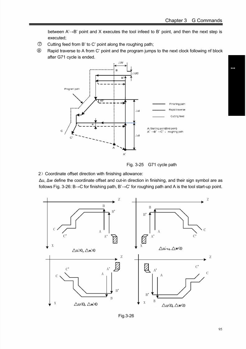
8/17/2019 980TDc CNC Turning Controller User Manual
http://slidepdf.com/reader/full/980tdc-cnc-turning-controller-user-manual 110/461
Chapter 3 G Commands
95
P r o gr ammi n g
between A’→B’ point and X executes the tool infeed to B’ point, and then the next step is
executed;
⑦ Cutting feed from B’ to C’ point along the roughing path;
⑧ Rapid traverse to A from C’ point and the program jumps to the next clock following nf block
after G71 cycle is ended.
Fig. 3-25 G71 cycle path
2)Coordinate offset direction with finishing allowance:
Δu, Δw define the coordinate offset and cut-in direction in finishing, and their sign symbol are as
follows Fig. 3-26: B→C for finishing path, B’→C’ for roughing path and A is the tool start-up point.
Fig.3-26

8/17/2019 980TDc CNC Turning Controller User Manual
http://slidepdf.com/reader/full/980tdc-cnc-turning-controller-user-manual 111/461
GSK980TDc Turning CNC System User Manual
96
P r o gr ammi n g
Type II:
The type II is different from the type I as follows:
1)Relative definition: more one parameter than the type I .
J:When J is not input or J is not 1, the system does not execute the run along the roughing
contour; J=1: the system executes the run along the roughing contour.2)The system does not execute the monotonous increasing or the monotonous decreasing
along X external contour, and the workpiece can be up to 10 grooves as follows:
Fig. 3-26-1(type Ⅱ)
But, the Z external contour must be the monotonous increasing or the monotonous
decreasing, and the following contour cannot be machined:
Fig. 3-26-2(type Ⅱ)
3)The first tool cutting need not the vertical: the machining can be executed when Z is the
monotonous change shape as follows:
Fig. 3-26-3

8/17/2019 980TDc CNC Turning Controller User Manual
http://slidepdf.com/reader/full/980tdc-cnc-turning-controller-user-manual 112/461
Chapter 3 G Commands
97
P r o gr ammi n g
4) After the turning, the system should execute the tool retraction, the retraction travel is
specified by R(e)or No. 52 as follows:
Fig. 3-26-4(typeⅡ)
5)Command execution process:roughing path A->H
Fig. 3-26-5(typeⅡ)
Notes:
ns block is only G00, G01. When the workpiece is type II, the system must specify the two
axes X(U) and Z(W), and W0 must be specified when Z does not move;
For type II, only X finishing allowance can be specified; when Z finishing allowance is
specified, the whole machining path offsets, and it can be specified to 0;
For type II, after the current grooving is completed to execute the next, the tool approaches
the workpiece(remark 25 and 26) in the remainder tool retraction distance at G1 speed; when
the tool retraction is 0 or the remainder distance is less than the tool retraction, and the tool
approaches the workpiece at G1 speed;
Some workpiece without remarking the type I or the type II adapts the both;
For the finishing path(ns~nf block),Z dimension must be monotonous change(always
increasing or decreasing), X dimension in the type I must be monotonous change and does
not need in the type II;
ns~nf blocks in programming must be followed G71 blocks. If they are in front of G71 blocks,the system automatically searches and executes ns~nf blocks, and then executes the next
program following nf block after they are executed, which causes the system executes ns~nf

8/17/2019 980TDc CNC Turning Controller User Manual
http://slidepdf.com/reader/full/980tdc-cnc-turning-controller-user-manual 113/461
GSK980TDc Turning CNC System User Manual
98
P r o gr ammi n g
blocks repetitively;
ns~nf blocks are used for counting the roughing path and the blocks are not executed when
G71 is executed. F, S, T commands of ns~nf blocks are invalid when G71 is executed, at the
moment, F, S, T commands of G71 blocks are valid. F, S, T of ns~nf blocks are valid when
executing ns~nf to command G70 finishing cycle; In ns~nf blocks, there are only G commands: G00, G01, G02, G03, G04, G05, G6.2, G6.3,
G7.2, G7.3, G96, G97, G98, G99, G40, G41, G42 and the system cannot call subprograms
(M98/M99);
G96, G97, G98, G99, G40, G41, G42 are invalid when G71 is executed, and are valid when
G70 is executed;
When G71 is executed, the system can stop the automatic run and manual traverse, but
return to the position before manual traversing when G71 is executed again, otherwise, the
following path will be wrong;
When the system is executing the feed hold or single block, the program pauses after the
system has executed end point of current path;
d , u are specified by the same U and different with or without being specified P, Q
commands;
G71 cannot be executed in MDI, otherwise, the system alarms;
There are no the same block number in ns~nf when compound cycle commands are
executed repetitively in one program;
The tool retraction point should be high or low as possible to avoid crashing the workpiece.
Example:Fig. 3-73(Type I)
Fig. 3-27
Program: O0004;
G00 X200 Z10 M3 S800; (Spindle clockwise with 800 r/min)
G71 U2 R1 F200; (Cutting depth each time 4mm, tool retraction 2mm [in
diameter])
G71 P80 Q120 U0.5 W0.2; (roughing a---e, machining allowance: X, 1mm;Z, 2mm)

8/17/2019 980TDc CNC Turning Controller User Manual
http://slidepdf.com/reader/full/980tdc-cnc-turning-controller-user-manual 114/461
Chapter 3 G Commands
99
P r o gr ammi n g
N80 G00 X40 S1200; (Positioning)
G01 Z-30 F100 ; (a→b)
X60 W-30; (b→c) a→b→c→d→e blocks for finishing path
W-20; (c→d)
N120 X100 W-10; (d→e)
G70 P80 Q120; (a---e blocks for finishing path)
M30; (End of block)
3.20.2 Radial roughing cycle G72
Command format:G72 W(Δd) R(e) F S T ; ⑴
G72 P(ns) Q(nf) U(Δu) W(Δw); ⑵
N (ns) .....;
........;
....F;
....S;
....; ⑶
·
N (nf).....;
Command function: G72 is divided into three parts:
⑴ 1st blocks for defining the travels of tool infeed and tool retraction, the cutting speed, the
spindle speed and the tool function in roughing;⑵ 2nd blocks for defining the block interval, finishing allowance;
⑶ 3rd blocks for some continuous finishing path, counting the roughing path without being
executed actually when G72 is executed.
According to the finishing path, the finishing allowance, the path of tool infeed and retract tool,
the system automatically counts the path of roughing, the tool cuts the workpiece in paralleling with Z,
and the roughing is completed by multiple executing the cutting cycle tool infeed→cutting feed→tool
retraction. The starting point and the end point of G72 are the same one. The command is applied to
the formed roughing of non-formed rod.
Relevant definit ions:
Finishing path: the above-mentioned Part ⑶ of G71(ns~nf block)defines the finishing path,
and the starting point of finishing path (i.e. starting point of ns block)is the same
these of starting point and end point of G72, called A point; the first block of
finishing path(ns block)is used for Z rapid traversing or cutting feed, and the end
point of finishing path is called to B point; the end point of finishing path(end
point of nf block)is called to C point. The finishing path is A→B→C.
Roughing path: The finishing path is the one after offsetting the finishing allowance(Δu, Δw) and
is the path contour formed by executing G72. A, B, C point of finishing path after
offset corresponds separately to A’, B’, C’ point of roughing path, and the final
continuous cutting path of G72 is B’→C’ point.
Δd: it is Z cutting in roughing, its value: 0.001~99.999(unit: mm/inch) without sign symbol, and
the direction of tool infeed is determined by ns block traverse direction. the specified value
8/17/2019 980TDc CNC Turning Controller User Manual
http://slidepdf.com/reader/full/980tdc-cnc-turning-controller-user-manual 115/461
GSK980TDc Turning CNC System User Manual
100
P r o gr ammi n g
Δd is reserved and the data value is switched to the corresponding value to save to No.051
after W(Δd) is executed. The value of system parameter No.051 is regarded as the tool
infeed clearance when R(e) is not input.
e: it is Z tool retraction clearance in roughing, its value: 0~99.999(unit: mm) without sign
symbol, and the direction of tool retraction is opposite to that of tool infeed, the specified
value e is reserved and the data value is switched to the corresponding value to save to
No.052 after R(e) is executed. The value of system parameter No.052 is regarded as the
tool retraction clearance when R(e) is not input.
ns: Block number of the first block of finishing path.
nf: Block number of the last block of finishing path.
Δu:it is X finishing allowance in roughing, its range: ±99999999×least input increment(X
coordinate offset of roughing contour corresponding to the finishing path, i.e. X absolute
coordinate difference between A’ and A.(diameter, unit: mm/inch, with sign symbol).
Δw:it is Z finishing allowance in roughing, its range: ±99999999×least input increment(Z
coordinate offset of roughing contour corresponding to the finishing path, i.e. Z absolutecoordinate difference between A’ and A.(diameter, unit: mm/inch, with sign symbol).
F: Cutting feedrate; S: Spindle speed; T: Tool number, tool offset number.
M, S, T, F: They can be specified in the first G72 or the second ones or program ns~nf. M, S, T,
F functions of M, S, T, F blocks are invalid in G72, and they are valid in G70 finishing blocks.
Execution process: Fig. 3-28
①X rapidly traverses to A’ from A point, X travel is Δu, and Z travel is Δw;
②X moves from A’ is Δd( tool infeed), ns block is for tool infeed at rapid traverse speed
with G0, is for tool infeed at G72 feedrate F in G1, and its direction of tool infeed is
that of A→B point;③X executes the cutting feeds to the roughing path, and its direction is the same that of
X coordinate B→C point;
④X, Z execute the tool retraction e (45°straight line)at feedrate, the directions of tool
retraction is opposite to that of tool infeed ;
⑤X rapidly retracts at rapid traverse speed to the position which is the same that of Z
coordinate;
⑥ After Z tool infeed (Δd+e)again is executed, the end point of traversing tool is still on
the middle point of straight line between A’ and B’(the tool does not reach or exceed
B’), and after Z executes the tool infeed (Δd+e)again, is executed;③ after the tool
infeed (Δd+e) is executed again, the end point of tool traversing reaches B’ point or
exceeds the straight line between A’→B’ point and Z executes the tool infeed to B’
point, and then the next step is executed;
⑦Cutting feed from B’ to C’ point along the roughing path;
⑧Rapidly traverse to A from C’ point and the program jumps to the next clock following
nf block after G71 cycle is completed.

8/17/2019 980TDc CNC Turning Controller User Manual
http://slidepdf.com/reader/full/980tdc-cnc-turning-controller-user-manual 116/461
Chapter 3 G Commands
101
P r o gr ammi n g
Fig. 3-28
Command specifications:
ns~nf blocks in programming must be followed G72 blocks. If they are in the front of G72
blocks, the system automatically searches and executes ns~nf blocks, and then executes the
next program following nf block after they are executed, which causes the system executes
ns~nf blocks repetitively;
ns~nf blocks are used for counting the roughing path and the blocks are not executed when
G72 is executed. F, S, T commands of ns~nf blocks are invalid when G72 is executed, at the
moment, F, S, T commands of G72 blocks are valid. F, S, T of ns~nf blocks are valid when
executing ns~nf to command G70 finishing cycle;
There are G00, G01 without the word X(U) in ns block, otherwise the system alarms;
The dimensions in X, Z direction must be changed monotonously (always increasing or
reducing) for the finishing path;
In ns~nf blocks, there are only G commands: G01, G02, G03, G04, G05, G6.2, G6.3, G7.2,
G7.3, G96, G97, G98, G99, G40, G41, G42 and the system cannot call subprograms
(M98/M99);
G96, G97, G98, G99, G40, G41, G42 are invalid when G72 is executed, and are valid when
G70 is done;
When G72 is executed, the system can stop the automatic run and manual traverse, but
return to the position before manual traversing when G72 is executed again, otherwise, the
following path will be wrong;
When the system is executing the feed hold or single block, the program pauses after the
system has executed end point of current path;
d , u are specified by the same U and different with or without being specified P, Q
commands;
There are no the same block number in ns~nf when compound cycle commands are
executed repetitively in one program; G72 cannot be executed in MDI, otherwise, the system alarms;
The tool retraction point should be high or low as possible to avoid crashing the workpiece.

8/17/2019 980TDc CNC Turning Controller User Manual
http://slidepdf.com/reader/full/980tdc-cnc-turning-controller-user-manual 117/461
GSK980TDc Turning CNC System User Manual
102
P r o gr ammi n g
Coordinate offset direction with finishing allowance:
Δu, Δw define the coordinate offset and its direction of cut-in in finishing, and their sign symbol
are as follows Fig. 3-29: B→C for finishing path, B’→C’ for roughing path and A is the tool start-up
point.
Fig.3-75
Example:Fig. 3-30
Fig.3-30
Program:
O0005;
G00 X176 Z10 M03 S500 (Change No.2 tool and execute its compensation, spindle
CW rotation with 500 r/min)
G72 W2.0 R0.5 F300; (Tool infeed 2mm, tool retraction 0.5mm)
G72 P10 Q20 U0.2 W0.1; (Roughing a--d,X roughing allowance 0.2mm and Z 0.1mm)
Fig.3-29
8/17/2019 980TDc CNC Turning Controller User Manual
http://slidepdf.com/reader/full/980tdc-cnc-turning-controller-user-manual 118/461
Chapter 3 G Commands
103
P r o gr ammi n g
N10 G00 Z-55 S800 ; (Rapid traverse)
G01 X160 F120; (Infeed to a point)
X80 W20; (Machining a—b) Blocks for finishing path
W15; (Machining b—c)
N20 X40 W20 ; (Machining c—d)
G70 P050 Q090 M30; (Finishing a—d)
3.20.3 Closed cutting cycle G73
Command format: G73 U(Δi) W (Δk) R (d) F S T ; ⑴
G73 P(ns) Q(nf) U(Δu) W(Δw) ; ⑵
N (ns) .....;
.......;
....F;
....S; ⑶
....;
·
N (nf) .....;
Command functions: G73 is divided into three parts:
⑴ Blocks for defining the travels of tool infeed and tool retraction, the cutting speed, the spindle
speed and the tool function when roughing;
Blo⑵ cks for defining the block interval, finishing allowance;
Blocks for some continuous finishing path, counting the roughing path without being⑶
executed actually when executing G73.
According to the finishing allowance, the travel of tool retraction and the cutting times, the system
automatically counts the travel of roughing offset, the travel of each tool infeed and the path of
roughing, the path of each cutting is the offset travel of finishing path, the cutting path
approaches gradually the finishing one, and last cutting path is the finishing one according to the
finishing allowance. The starting point and end point of G73 are the same one, and G73 is
applied to roughing for the formed rod. G73 is non-modal and its path is shown in Fig.3-31.
Relevant definit ions:
Finishing path: The above-mentioned Part 3 of G73 (ns~nf block)defines the finishing path,
and the starting point of finishing path (start point of ns block)is the same these
of starting point and end point of G73, called A point; the end point of the firstblock of finishing path(ns block)is called B point; the end point of finishing
path(end point of nf block) is called C point. The finishing path is A→B→C.
Roughing path: It is one group of offset path of finishing one, and the roughing path times are
the same that of cutting. After the coordinates offset, A, B, C of finishing path
separately corresponds to An, Bn , Cn of roughing path(n is the cutting times,
the first cutting path is A1, B1, C1 and the last one is Ad, Bd, Cd). The
coordinates offset value of the first cutting compared to finishing path is
(Δi×2+Δu, Δw+Δk) (diameter programming) , the coordinates offset value of
the last cutting compared to finishing path is(Δu, Δw) , the coordinates offset
value of each cutting compared to the previous one is as follows:Δi: It is X tool retraction clearance in roughing, and its range is ±99999999× least input
increment (radius, unit: mm/inch, with sign symbol) , Δi is equal to X coordinate offset
8/17/2019 980TDc CNC Turning Controller User Manual
http://slidepdf.com/reader/full/980tdc-cnc-turning-controller-user-manual 119/461
GSK980TDc Turning CNC System User Manual
104
P r o gr ammi n g
value (radius value) of A1 point compared to Ad point. The X total cutting travel(radius
value) is equal to |Δi| in roughing, and X cutting direction is opposite to the sign of Δi: Δi
>0, the system executes X negative cutting in roughing. It is reserved after Δi specified
value is executed and the data is switched to the corresponding value to save to NO.053.
The No.053 value is regarded as X tool retraction clearance in roughing when U(Δi) is
not input.
Δk: It is Z tool retraction clearance in roughing, and its range is ±99999999× least input
increment (radius, unit: mm/inch, with sign symbol) , Δk is equal to Z coordinate offset
value (radius value) of A1 point compared to Ad point. Z total cutting travel(radius value)
is equal to |Δk| in roughing, and Z cutting direction is opposite to the sign of Δk: Δi>0,
the system executes Z negative cutting in roughing. It is reserved after Δk specified
value is executed and the data is switched to the corresponding value to save to NO.054.
The No.054 value is regarded as Z tool retraction clearance in roughing when W(Δk) is
not input.
d: It is the cutting times 1~9999 (unit: times). R5 means the closed cutting cycle is completedby 5 times cutting. R (d) is reserved after it is executed and NO.055 value is rewritten to d
(unit: times). No.055 value is regarded as the cutting times when R(d) is not input. When
the cutting times is 1, the system completes the closed cutting cycle based on 2 times
cutting.
ns: Block number of the first block of finishing path.
nf: Block number of the last block of finishing path.
Δu: It is X finishing allowance and its range is ±99999999× least input increment (diameter,
unit: mm/inch, with sign symbol) and is the X coordinate offset of roughing path
compared to finishing path, i.e. the different value of X absolute coordinates of A 1
compared to A. Δu>0,it is the offset of the last X positive roughing path compared tofinishing path. The system defaults Δu=0 when U(Δu) is not input, i.e. there is no X
finishing allowance for roughing cycle.
Δw: It is Z finishing allowance and its range is ±99999999× least input increment (diameter,
unit: mm/inch, with sign symbol) and is the X coordinate offset of roughing path
compared to finishing path, i.e. the different value of Z absolute coordinates of A1
compared to A. Δw>0,it is the offset of the last X positive roughing path compared to
finishing path. The system defaults Δw=0 when W(Δw) is not input, i.e. there is no Z
finishing allowance for roughing cycle.
F: Feedrate; S: Spindle speed; T: Tool number, tool offset number.
M, S, T, F: They can be specified in the first G73 or the second ones or program ns~nf. M, S,
T, F functions of M, S, T, F blocks are invalid in G73, and they are valid in G70 finishing blocks.
Execution process: (Fig. 3-31)
① A→ A1: Rapid traverse;
②
First roughing A1→B1→C1 :
A1→B1: Rapid traverse speed in ns block in G0, cutting feedrate specified by G73 in ns block
in G1;
B1→C1: Cutting feed.
③ C1→ A2: Rapid traverse.
④
Second roughing A2→B2→C2 :
A2→B2: Rapid traverse speed in ns block in G0, cutting feedrate specified by G73 in ns block
in G1;

8/17/2019 980TDc CNC Turning Controller User Manual
http://slidepdf.com/reader/full/980tdc-cnc-turning-controller-user-manual 120/461
Chapter 3 G Commands
105
P r o gr ammi n g
B2→C2: Cutting feed.
⑤ C2→ A3: Rapid traverse:
…………
No. n times roughing, An→Bn→Cn :
An→Bn: ns Rapid traverse speed in ns block in G0, cutting feedrate specified by G73 in ns
block in G1;
Bn→Cn: Cutting feed.
Cn→ An+1: Rapid traverse;
…………
Last roughing, Ad→Bd→Cd :
Ad→Bd: Rapid traverse speed in ns block in G0, cutting feedrate specified by G73 in ns block
in G1;
Bd→Cd: Cutting feed.
Cd→ A: Rapid traverse to starting point;
A1
A3
A2
A4
AnAd
A
B1
B3
B2
B4Bn
Bd
B
C1
C3C2
C4Cn
CdC
w
K+w
u/2i+u/2
Finishing path
A: Starting point(End point)
An—Bn—Cn: roughing path
Rapid traverse
Cutting feed
B
Fig. 3-31 G73 path
Command specifications:
ns~nf blocks in programming must be followed G73 blocks. If they are in the front of G73blocks, the system automatically searches and executes ns~nf blocks, and then executes
the next program following nf block after they are executed, which causes the system
executes ns~nf blocks repetitively.
ns~nf blocks are used for counting the roughing path and the blocks are not executed when
G73 is executed. F, S, T commands of ns~nf blocks are invalid when G71 is executed, at the
moment, F, S, T commands of G73 blocks are valid. F, S, T of ns~nf blocks are valid when
executing ns~nf to command G70 finishing cycle.
There are only G00, G01 in ns block.
I n ns~nf blocks, there are only G commands: G00, G01, G02, G03, G04, G05, G6.2, G6.3,G7.2, G7.3, G96, G97, G98, G99, G40, G41, G42 and the system cannot call subprograms
(M98/M99) .

8/17/2019 980TDc CNC Turning Controller User Manual
http://slidepdf.com/reader/full/980tdc-cnc-turning-controller-user-manual 121/461
GSK980TDc Turning CNC System User Manual
106
P r o gr ammi n g
G96, G97, G98, G99, G40, G41, G42 are invalid when G73 is executed, and are valid when
G70 is executed.
When G73 is executed, the system can stop the automatic run and manual traverse, but
return to the position before manual traversing when G73 is executed again, otherwise, the
following path will be wrong.
When the system is executing the feed hold or single block, the program pauses after the
system has executed end point of current path.
i , u are specified by the same U and Δk , Δw are specified by the same U, and they are
different with or without being specified P,Q commands.
G73 cannot be executed in MDI, otherwise, the system alarms.
There are no the same block number in ns~nf when compound cycle commands are
executed repetitively in one program.
The tool retraction point should be high or low as possible to avoid crashing the workpiece.
Coordinate offset direction with finishing allowance:
Δi, Δk define the coordinates offset and its direction of roughing; Δu, Δw define the coordinateoffset and the cut-in direction in finishing, and their sign symbols are as follows Fig. 3-32: A is tool
start-up point, B→C for workpiece contour, B’→C’ for roughing contour and B’’→C’’ for finishing path.
1)Δi<0 Δk>0, u<0 Δw>0; 2)Δi>0 Δk>0, u>0 Δw>0;
A ’
B
A
Z
X
Z
X
B ’
A ’’
B ’’
CC ’
C ’’
A
A ’ A ’’
B
B ’
B ’’
CC ’
C ’’
3)Δi<0 Δk <0, u<0 Δw<0; 4)Δi>0 Δk <0, u>0 Δw<0;
Z
X
Z
X
AA’
A’’
C
C’C
’’
B
B’ B’’
A’
B’
B’’
C’
A
A’’
B
C
C’’
Fig.3-32

8/17/2019 980TDc CNC Turning Controller User Manual
http://slidepdf.com/reader/full/980tdc-cnc-turning-controller-user-manual 122/461
Chapter 3 G Commands
107
P r o gr ammi n g
Example:Fig. 3-33
starting point(200,10)
1
0.5/2
0.3
0.5/2
0.3
Fig.3-34
Program: O0006;
G99 G00 X200 Z10 M03 S500; (Specify feedrate per rev and position starting point and
start spindle)
G73 U1.0 W1.0 R3 ; (X tool retraction with 2mm, Z 1mm)
G73 P14 Q19 U0.5 W0.3 F0.3 ; (X roughing with 0.5 allowance and Z 0.3mm)
N14 G00 X80 W-40 ;
G01 W-20 F0.15 S600 ;
X120 W-10 ;
W-20 ; Blocks for finishing
G02 X160 W-20 R20 ;
N19 G01 X180 W-10 ;
G70 P14 Q19 M30; (Finishing)
3.20.4 Finishing cyc le G70
Command format: G70 P(ns) Q(nf) ;Command function: The tool executes the finishing of workpiece from starting point along with
the finishing path defined by ns~nf blocks. After executing G71, G72 or
G73 to roughing, execute G70 to finishing and single cutting of finishing
allowance is completed. The tool returns to starting point and execute the
next block following G70 block after G70 cycle is completed.
ns: Block number of the first block of finishing path.
nf: Block number of the last block of finishing path.
G70 path is defined by programmed one of ns~nf blocks. Relationships of relative position
of ns, nf block in G70~G73 blocks are as follows:

8/17/2019 980TDc CNC Turning Controller User Manual
http://slidepdf.com/reader/full/980tdc-cnc-turning-controller-user-manual 123/461
GSK980TDc Turning CNC System User Manual
108
P r o gr ammi n g
........
G71/G72/G73 ……;
N (ns) ......
........
· F· S Blocks for finishing path
·
·
N (nf)……
...
G70 P(ns) Q(nf);
...
Command specifications:
ns~nf blocks in programming must be followed G70 blocks. If they are in the front of G71
blocks, the system automatically searches and executes ns~nf blocks, and then executes
the next program following nf block after they are executed, which causes the system
executes ns~nf blocks repetitively.
F, S, T in ns~nf blocks are valid when executing ns~nf to command G70 finishing cycle.
G96, G97, G98, G99, G40, G41, G42 are valid in G70;
When G70 is executed, the system can stop the automatic run and manual traverse, but
return to the position before manual traversing when G70 is executed again, otherwise, the
following path will be wrong.
When the system is executing the feed hold or single block, the program pauses after the
system has executed end point of current path. G70 cannot be executed in MDI, otherwise, the system alarms.
There are no the same block number in ns~nf when compound cycle commands are
executed repetitively in one program.
The tool retraction point should be high or low as possible to avoid crashing the workpiece.
3.20.5 Axial grooving multip le cycle G74
Command format: G74 R(e) ;
G74 X(U) Z(W) P(Δi) Q(Δk) R(Δd) F ;
Command function: Axial (X axis) tool infeed cycle compounds radial discontinuous cuttingcycle: Tool infeeds from starting point in radial direction( Z), retracts, infeeds again,
and again and again, and last tool retracts in axial direction, and retracts to the Z
position in radial direction, which is called one radial cutting cycle; tool infeeds in axial
direction and execute the next radial cutting cycle; cut to end point of cutting, and
then return to starting point (starting point and end point are the same one in G74),
which is called one radial grooving compound cycle. Directions of axial tool infeed
and radial tool infeed are defined by relative position between end point X(U) Z(W)
and starting point of cutting. G75 is used for machining radial loop groove or column
surface by radial discontinuously cutting, breaking stock and stock removal.
Relevant definitions:Starting point of axial cutting cycle: starting position of axial tool infeed for each axial cutting
cycle, defining with An(n=1,2,3……), Z coordinate of An is

8/17/2019 980TDc CNC Turning Controller User Manual
http://slidepdf.com/reader/full/980tdc-cnc-turning-controller-user-manual 124/461
Chapter 3 G Commands
109
P r o gr ammi n g
the same that of starting point A, the different value of X
coordinate between An and An-1 is Δi. The starting point A1
of the first axial cutting cycle is the same as the starting
point A, and the X coordinate of starting point (Af ) of the
last axial cutting cycle is the same that of cutting end point.
End point of axial tool infeed: starting position of axial tool infeed for each axial cutting cycle,
defining with Bn(n=1,2,3……), Z coordinate of Bn is the same
that of cutting end point, X coordinate of Bn is the same that of
An , and the end point (Bf ) of the last axial tool infeed is the
same that of cutting end point.
End point of radius tool retraction: end position of radius tool infeed (travel of tool infeed is Δd)
after each axial cutting cycle reaches the end point of axial
tool infeed, defining with Cn(n=1,2,3……), Z coordinate of
Cn is the same that of cutting end point, and the different
value of X coordinate between Cn and An is Δd;
End point of axial cutting cycle: end position of axial tool retraction from the end point of
radius tool retraction, defining with Dn(n=1, 2, 3……), Z
coordinate of Dn is the same that of starting point, X
coordinate of Dn is the same that of Cn (the different value
of X coordinate between it and An is Δd);
Cutting end point: it is defined by X(U) Z(W) , and is defined with Bf of the last axial
tool infeed.
R(e) : it is the tool retraction clearance after each axial(Z) tool infeed, and its range is
0~99.999(unit:mm) without sign symbols. The specified value is reserved validly after
R(e) is executed and the data is switched to the corresponding value to save to NO.056.The NO.056 value is regarded as the tool retraction clearance when R(e) is not input.
X: X absolute coordinate value of cutting end point Bf (unit: mm).
U: Different value of X absolute coordinate between cutting end point Bf and starting point.
Z: Z absolute coordinate value of cutting end point Bf (unit: mm).
W: Different value of Z absolute coordinates between cutting end point Bf and starting point.
P(Δi) :radial(X) cutting for each axial cutting cycle , range: 0<Δi≤ 9999999× least input
increment (unit: least input increment, diameter value, without sign symbol).
Q(Δk):radial(Z) cutting for each axial cutting cycle, range: 0<Δk≤ 9999999× least input
increment (unit: least input increment, diameter value, without sign symbol).
R(Δd) : radial (X) tool retraction after cutting to end point of axial cutting, range: 0~99999999×least input increment (unit: mm/inch, diameter value, without sign symbol).. The radial (X)
tool retraction clearance is 0 when the system defaults the axial cutting end point. The
system defaults the tool retraction is executed in positive direction when X(U) and P(Δi)
are omitted.
Execution process: (Fig. 3-34)
①
Axial (Z) cutting feed k from the starting point of axial cutting cycle, feed in Z
negative direction when the coordinates of cutting end point is less than that of
starting point in Z direction, otherwise, feed in Z positive direction;
Axial (Z) rapid tool retraction e and its direction is opposite to the feed direction of ①;
③
X executes the cutting feed (Δk+e) again, the end point of cutting feed is still in it
between starting point An of axial cutting cycle and end point of axial tool infeed, Z
executes the cutting feed (Δk+e)again and execute ②; after Z executing the cutting

8/17/2019 980TDc CNC Turning Controller User Manual
http://slidepdf.com/reader/full/980tdc-cnc-turning-controller-user-manual 125/461
GSK980TDc Turning CNC System User Manual
110
P r o gr ammi n g
feed (Δk+e)again, the end point of cutting feed is on Bn or is not on it between An and
Bn cutting feed to Bn in Z direction and then execute ④;
④ Radial(X) rapid tool retraction d to Cn , when X coordinate of B f (cutting end point)
is less than that of A (starting point), retract tool in X positive, otherwise, retract tool
in X negative direction;
⑤
Axial(Z axial) rapid retract tool to Dn, No. n axial cutting cycle is completed. If the
current axial cutting cycle is not the last one, execute ⑥ ; if it is the previous one
before the last axial cutting cycle, execute ⑦;
⑥
Radial(X axial)rapid tool infeed, and it direction is opposite to ④ retract tool. If the end
point of tool infeed is still on it between A and A f (starting point of last axial cutting
cycle) after X executes the tool infeed (d+i) , i.e. Dn→ An+1 and then execute ①
(start the next axial cutting cycle); if X end point of tool infeed is not on it between Dn
and Af after tool infeed (d+i), rapidly traverse to Af and execute ① to start the
first axial cutting cycle;
⑦ X rapidly traverse to return to A, and G74 is completed.
Fig. 3-34 G74 path
Command specifications:
The cycle movement is executed by Z(W) and P(Δk) blocks of G74, and the movement is not
executed if only “G74 R(e) ; ” block is executed;
Δd and e are specified by the same address and whether there are Z(W) and P(Δk) word or
not in blocks to distinguish them;
The tool can stop in Auto mode and traverse in Manual mode when G74 is executed, but the
tool must return to the position before executing in Manual mode when G74 is executed again,
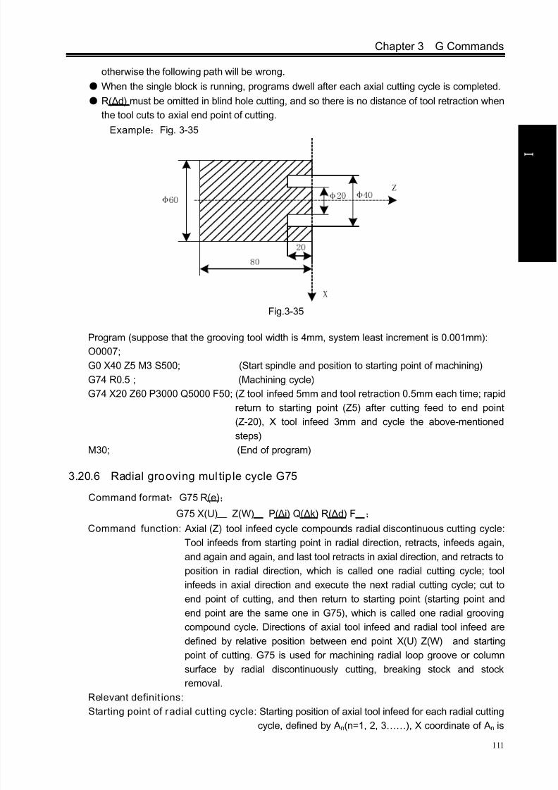
8/17/2019 980TDc CNC Turning Controller User Manual
http://slidepdf.com/reader/full/980tdc-cnc-turning-controller-user-manual 126/461
Chapter 3 G Commands
111
P r o gr ammi n g
otherwise the following path will be wrong.
When the single block is running, programs dwell after each axial cutting cycle is completed.
R(Δd) must be omitted in blind hole cutting, and so there is no distance of tool retraction when
the tool cuts to axial end point of cutting.
Example:Fig. 3-35
Fig.3-35
Program (suppose that the grooving tool width is 4mm, system least increment is 0.001mm):
O0007;
G0 X40 Z5 M3 S500; (Start spindle and position to starting point of machining)
G74 R0.5 ; (Machining cycle)
G74 X20 Z60 P3000 Q5000 F50; (Z tool infeed 5mm and tool retraction 0.5mm each time; rapid
return to starting point (Z5) after cutting feed to end point
(Z-20), X tool infeed 3mm and cycle the above-mentioned
steps)
M30; (End of program)
3.20.6 Radial grooving mul tip le cycle G75
Command format:G75 R(e);
G75 X(U) Z(W) P(Δi) Q(Δk) R(Δd) F ;
Command function: Axial (Z) tool infeed cycle compounds radial discontinuous cutting cycle:
Tool infeeds from starting point in radial direction, retracts, infeeds again,
and again and again, and last tool retracts in axial direction, and retracts to
position in radial direction, which is called one radial cutting cycle; tool
infeeds in axial direction and execute the next radial cutting cycle; cut to
end point of cutting, and then return to starting point (starting point and
end point are the same one in G75), which is called one radial grooving
compound cycle. Directions of axial tool infeed and radial tool infeed are
defined by relative position between end point X(U) Z(W) and starting
point of cutting. G75 is used for machining radial loop groove or column
surface by radial discontinuously cutting, breaking stock and stock
removal.
Relevant definit ions:
Starting point of radial cutting cycle: Starting position of axial tool infeed for each radial cutting
cycle, defined by An(n=1, 2, 3……), X coordinate of An is

8/17/2019 980TDc CNC Turning Controller User Manual
http://slidepdf.com/reader/full/980tdc-cnc-turning-controller-user-manual 127/461
GSK980TDc Turning CNC System User Manual
112
P r o gr ammi n g
the same that of starting point A, the different value of X
coordinate between An and An-1 is Δk. The starting point
A1 of the first radial cutting cycle is the same as the
starting point A, and Z starting point (A f ) of the last axial
cutting cycle is the same that of cutting end point.
End point of radial tool infeed: Starting position of radial tool infeed for each radial cutting
cycle, defined by Bn (n=1, 2, 3……), X coordinates of Bn is
the same that of cutting end point, Z coordinates of Bn is the
same that of An, and the end point (Bf ) of the last radial tool
infeed is the same that of cutting end point.
End point of axial tool retraction: End position of axial tool infeed (travel of tool infeed is Δd)
after each axial cutting cycle reaches the end point of axial
tool infeed, defining with Cn(n=1,2,3……), X coordinate of
Cn is the same that of cutting end point, and the different
value of Z coordinate between Cn and An is Δd;
End point of radial cutting cycle: End position of radial tool retraction from the end point of
axial tool retraction, defined by Dn(n=1, 2, 3……), X
coordinate of Dn is the same that of starting point, Z
coordinates of Dn is the same that of Cn (the different value
of Z coordinate between it and An is Δd);
Cutting end point: It is defined by X(U) Z(W) , and is defined with Bf of the last radial
tool infeed.
R(e) : It is the tool retraction clearance after each radial(X) tool infeed, its range is 0~99.999 (unit:
mm, radius value) without sign symbols. The specified value is reserved validly after R(e)
is executed and the data is switched and saved to No.056. NO.056 value is regarded as
the tool retraction clearance when R(e) is not input.
X: X absolute coordinate value of cutting end point Bf (unit: mm).
U: Different value of X absolute coordinate between cutting end point Bf and starting point.
Z: Z absolute coordinate value of cutting end point Bf (unit:mm).
W: Different value of Z absolute coordinate between cutting end point Bf and starting point A(unit:
mm).
P(Δi) : Radial(X) discontinuous tool infeed of each axial cutting cycle, its range: 0<Δi≤ 9999999
(IS_B)/ 0<Δk≤ 99999999(IS_C) (unit: least input increment, without sign symbol).
Q(Δk) : Axial(Z) discontinuous tool infeed of each radial cutting cycle, its range: 0 <Δk≤
9999999(IS_B)/0<Δk≤ 99999999( IS_C)(unit: least input increment, without sign
symbol)..
R(Δd): Axial (Z) tool retraction clearance after cutting to end point of radial cutting, its range:
0~99999999×least input increment(unit: mm/inch, without sign symbol).
The system defaults the tool retraction clearance is 0 after the radial cutting end point is
completed when R(Δd) is omitted.
The system defaults it executes the positive tool retraction when Z(W) and Q(Δk) are
omitted.

8/17/2019 980TDc CNC Turning Controller User Manual
http://slidepdf.com/reader/full/980tdc-cnc-turning-controller-user-manual 128/461
Chapter 3 G Commands
113
P r o gr ammi n g
Fig. 3-36 G75 path
Execution process: (Fig. 3-36)① Radial (X) cutting feed i from the starting point of radial cutting cycle, feed in X
negative direction when the coordinates of cutting end point is less than that of
starting point in X direction, otherwise, feed in X positive direction;
② Radial(X) rapid tool retraction e and its direction is opposite to the feed direction of ①;
③ X executes the cutting feed (Δk+e) again, the end point of cutting feed is still in it
between starting point An of radial cutting cycle and end point of radial tool infeed, X
executes the cutting feed (Δi+e) again and executes ②; after X cutting feed (Δi+e) is
executed again, the end point of X cutting feed is on Bn or is not on it between An and
Bn cutting feed to Bn and then execute4 ;
④
Axial(Z) rapid tool retraction d to Cn , when Z coordinate of Bf (cutting end point) isless than that of A (starting point), retract tool in Z positive, otherwise, retract tool in Z
negative direction;
⑤ Radial (Z) rapid retract tool to Dn, No. n radial cutting cycle is completed. The current
radial cutting cycle is not the last one, execute ⑥; if it is the previous one before the
last radial cutting cycle, execute ⑦;
⑥ Axial(X) rapid tool infeed, and it direction is opposite to ④ retract tool. If the end point
of tool infeed is still on it between A and Af (starting point of last radial cutting cycle)
after Z tool infeed (d+k), i.e. Dn→ An+1 and then execute ① (start the next radial
cutting cycle); if the end point of tool infeed is not on it between Dn and Af after Z tool
infeed (d+k), rapidly traverse to Af and execute ① to start the first radial cuttingcycle;
⑦ Z rapidly traverses to A, and G75 is completed.

8/17/2019 980TDc CNC Turning Controller User Manual
http://slidepdf.com/reader/full/980tdc-cnc-turning-controller-user-manual 129/461
GSK980TDc Turning CNC System User Manual
114
P r o gr ammi n g
Explanation:
The cycle movement is executed by X(W) and P(Δi) blocks of G75, and the movement is not
executed if only “G75 R(e) ; ” block is executed;
Δd and e are specified by the same address R and whether there are X(U) and P(Δi) words or
not in blocks to distinguish them;
The tool can stop in Auto mode and traverse in Manual mode when G75 is executed, but the
tool must return to the position before executing in Manual mode when G75 is executed again,
otherwise the following path will be wrong;
When the system is executing the feed hold or single block, the program pauses after the
system has executed end point of current path;
R(Δd) must be omitted in grooving, and so there is no tool retraction clearance when the tool
cuts to radial cutting end point.
Example:Fig.3-37
Fig. 3-37 G75 cutting
Program (suppose the grooving tool width is 4mm, the system least increment is 0.001mm):
O0008;
G00 X150 Z50 M3 S500; (Start spindle with 500 r/min)
G0 X125 Z-20; (Position to starting point of machining)
G75 R0.5 F150; (Machining cycle)
G75 X40 Z-50 P6000 Q3000; (X tool infeed 6mm every time, tool retraction 0.5mm,
rapid returning to starting point (X125) after infeeding
to end point (X40), Z tool infeed 3mm and cycle the
above-mentioned steps to continuously run programs)
G0 X150 Z50; (Return to starting point of machining)
M30; (End of program)
3.21 Thread Cutting Commands
GSK980TDc CNC system can machine many kinds of thread cutting, including metric/inch single,
multi threads, thread with variable lead and tapping cycle. Length and angle of thread run-out can be
changed, multiple cycle thread is machined by single sided to protect tool and improve smooth finish
of its surface. Thread cutting includes: continuous thread cutting G32, thread cutting with variable
lead G34, Z thread cutting G33, Thread cutting cycle G92, Multiple thread cutting cycle G76.The machine used for thread cutting must be installed with spindle encoder whose pulses are set
by No.070m. Drive ratio between spindle and encoder is set by No.110 and No.111. X or Z traverses
8/17/2019 980TDc CNC Turning Controller User Manual
http://slidepdf.com/reader/full/980tdc-cnc-turning-controller-user-manual 130/461
Chapter 3 G Commands
115
P r o gr ammi n g
to start machine after the system receives spindle signal per rev in thread cutting, and so one thread
is machined by multiple roughing, finishing without changing spindle speed.
The system can machine many kinds of thread cutting, such as thread cutting without tool
retraction groove. There is a big error in the thread pitch because there are the acceleration and the
deceleration at the starting and ending of X and Z thread cutting, and so there is length of thread
lead-in and distance of tool retraction at the actual starting and ending of thread cutting.
X, Z traverse speeds are defined by spindle speed instead of cutting feedrate override in thread
cutting when the pitch is defined. The spindle override control is valid in thread cutting. When the
spindle speed is changed, there is error in pitch caused by X and Z acceleration/deceleration, and so
the spindle speed cannot be changed and the spindle cannot be stopped in thread cutting, which will
cause tool and workpiece to be damaged.
3.21.1 Thread cutting with constant lead G32
Command format: G32 X(U)_ Z(W)_ F(I)_ J_ K_ Q_
Command function: The path of tool traversing is a straight line from starting point to end point asFig.3-33; the longer moving distance from starting point to end point(X in radius value) is
called as the long axis and another is called as the short axis. In course of motion, the long
axis traverses one lead when the spindle rotates one revolution, and the short axis and
the long axis execute the linear interpolation. Form one spiral grooving with variable lead
on the surface of workpiece to realize thread cutting with constant lead. Metric pitch and
inch pitch are defined respectively by F, I. Metric or inch straight, taper, end face thread
and continuous multi-section thread can by machined in G32.
Command specifications:
G32 is modal;
Pitch is defined to moving distance when the spindle rotates one rev(X in radius);Execute the straight thread cutting when X coordinates of starting point and end point are the
same one(not input X or U);
Execute the end face thread cutting when X coordinates of starting point and end point are the
same one(not input Z or W);
Execute the cutting taper thread when X and Z coordinates of starting point and end point are
different;
Related definitions:
F: Metric pitch is moving distance of long axis when the spindle rotates one rev: 0.001 mm~500
mm. After F is executed, it is valid until F with specified pitch is executed again.
I: Teeth per inch. It is ones per inch(25.4 mm) in long axis, and also is circles of spindle rotation
when the long axis traverses one inch(25.4 mm) :0.06tooth/inch~25400tooth/inch. After I is
executed, it is valid until I with specified pitch is executed again. The metric, inch input both
express the teeth per inch thread.
J: Movement in the short axis in thread run-out, its range: ±99999999× least input increment with
negative sign; if the short axis is X, its value is specified with the radius; J value is the modal
parameter.
K: Length in the long axis in thread run-out, its range: ±99999999× least input increment. If the
long axis is X, its value is in radius without direction; K is modal parameter.
Q: Initial angle(offset angle)between spindle rotation one rev and starting point of thread cutting:
0~360000 (unit: 0.001 degree). Q is non-modal parameter, must be defined every time,
otherwise it is 00.

8/17/2019 980TDc CNC Turning Controller User Manual
http://slidepdf.com/reader/full/980tdc-cnc-turning-controller-user-manual 131/461
GSK980TDc Turning CNC System User Manual
116
P r o gr ammi n g
Q rules:
1. Its initial angle is 0° if Q is not specified;
2. For continuous thread cutting, Q specified by its following thread cutting block except for the
first block is invalid, namely Q is omitted even if it is specified;
3. Multi threads formed by initial angle is not more than 65535;
4. Q unit : 0.0010 . Q180000 is input in program if it offsets 1800 with spindle one-turn; if Q180 or
Q180.0, it is 0.18°.
Difference between long axis and short axis is shown in Fig. 3-38.
X axis
Current point
Z axis
W
U / 2
X
Z
F x
Fz
a
E n d
p o i n t
Fig. 3-38 G32 path
Notes:
J, K are modal. The thread run-out is previous J, K value when they are omitted in the next
block in continuous thread cutting. Their mode are cancelled when no thread cutting are
executed;
There is no thread run-out when J, or J, K are omitted; K=J is the thread run-out value when K
is omitted;
There is no thread run-out when J=0 or J=0, K=0;
The thread run-out value J=K when J≠0,K=0;
There is no thread run-out when J=0 or K≠0;
If the current block is for thread and the next block is the same, the system does not test the
spindle encoder signal per rev at starting the next block to execute the direct thread cutting,
which function is called as continuous thread machining;
After the feed hold is executed, the system displays “Pause” and the thread cutting
continuously executes not to stop until the current block is executed completely; if the
continuous thread cutting is executed, the program run pauses after thread cutting blocks are
executed completely; In Single block, the program stops run after the current block is executed. The program stops
running after all blocks for thread cutting are executed;
Tool path
End point of G32 program
J
K

8/17/2019 980TDc CNC Turning Controller User Manual
http://slidepdf.com/reader/full/980tdc-cnc-turning-controller-user-manual 132/461
Chapter 3 G Commands
117
P r o gr ammi n g
The thread cutting decelerates to stop when the system resets, emergently stop or its drive
unit alarms.
Example: Pitch: 2mm. δ1 = 3mm,δ2 = 2mm,total cutting depth 2mm divided into two times cut-in.
Program:
O0009;
G00 X28 Z3; (First cut-in 1mm)
G32 X51 W-75 F2.0; (First taper cutting)
G00 X55; (Tool retraction)
W75; (Z returns to the starting point)
X27; (Second tool infeed 0.5mm)
G32 X50 W-75 F2.0; (Second taper thread cutting )
G00 X55; (Tool retraction)
W75 ; (Z returns to the starting point)M30;
3.21.2 Rigid thread cut ting G32.1
Command format:G32.1 X(U)__ Z(W)__ C(H)__F(I)__ S__;
Command function:The traditional thread interpolation calculates the current distance of the
movement of the feed axis based on the feedback pulse count of the position encoder
installed on the spindle, which can realize the feed axis to follow the thread
interpolation mode of the spindle. Its disadvantages are that there is a big error in the
thread lead in acceleration/deceleration. In the rigid thread interpolation mode, the
working of the spindle motor is the same that of the servo motor, and the
interpolations between the feed axis and the spindle execute the thread interpolation
to get the thread with high precision.
Command explanation:
G32.1 :rigid thread interpolation command;
C :start angle of thread interpolation;
(X,Z) :end point coordinates of thread interpolation;
F(I) :thread lead, F(I)> 0 right-hand thread, F(I)< 0 left-hand thread;
S :spindle speed;
Fig.3-39
Starting point
End point
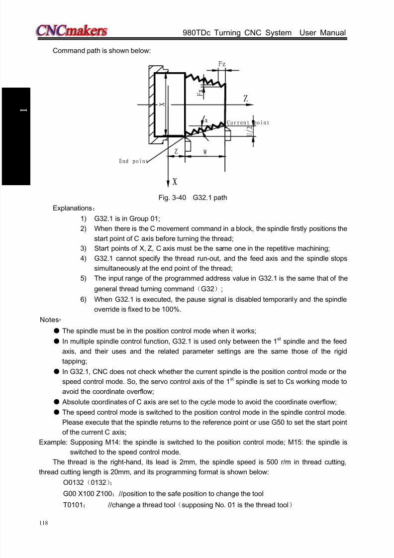
8/17/2019 980TDc CNC Turning Controller User Manual
http://slidepdf.com/reader/full/980tdc-cnc-turning-controller-user-manual 133/461
GSK980TDc Turning CNC System User Manual
118
P r o gr ammi n g
Command path is shown below:
W
U / 2
X
Z
F x
Fz
a
X
Z
End point
Current point
Fig. 3-40 G32.1 path
Explanations:
1) G32.1 is in Group 01;
2) When there is the C movement command in a block, the spindle firstly positions the
start point of C axis before turning the thread;
3) Start points of X, Z, C axis must be the same one in the repetitive machining;
4) G32.1 cannot specify the thread run-out, and the feed axis and the spindle stops
simultaneously at the end point of the thread;
5) The input range of the programmed address value in G32.1 is the same that of the
general thread turning command(G32);
6) When G32.1 is executed, the pause signal is disabled temporarily and the spindle
override is fixed to be 100%.
Notes:
The spindle must be in the position control mode when it works;
In multiple spindle control function, G32.1 is used only between the 1 st spindle and the feed
axis, and their uses and the related parameter settings are the same those of the rigid
tapping;
In G32.1, CNC does not check whether the current spindle is the position control mode or the
speed control mode. So, the servo control axis of the 1st spindle is set to Cs working mode to
avoid the coordinate overflow; Absolute coordinates of C axis are set to the cycle mode to avoid the coordinate overflow;
The speed control mode is switched to the position control mode in the spindle control mode.
Please execute that the spindle returns to the reference point or use G50 to set the start point
of the current C axis;
Example: Supposing M14: the spindle is switched to the position control mode; M15: the spindle is
switched to the speed control mode.
The thread is the right-hand, its lead is 2mm, the spindle speed is 500 r/m in thread cutting,
thread cutting length is 20mm, and its programming format is shown below:
O0132(0132);
G00 X100 Z100;//position to the safe position to change the tool
T0101; //change a thread tool(supposing No. 01 is the thread tool)
8/17/2019 980TDc CNC Turning Controller User Manual
http://slidepdf.com/reader/full/980tdc-cnc-turning-controller-user-manual 134/461
Chapter 3 G Commands
119
P r o gr ammi n g
G00 X25 Z2; //position to the thread starting point(supposing the shape has been made at
the last tool)
M14; //switch the spindle from speed control mode to position control mode(it is 0。
position after switch)
G50 C0; // set the zero of the rotary axis(it is important to set it because the operation isrelevant to the start angle of the following thread turning)
G32.1 Z-20 F2 S500 M08;//thread turning; the speeds of the spindle and the feed axis are0 in
end point
G00 X30; //tool retraction
X24.5 Z2 C0; //return to thread starting point, and prepare for repetitively machining
G32.1 Z-20 F2 S500; // repetitively machine
....; //repetitively machine
G00 X100; //tool retraction
Z100; //return to tool change positionM15; //switch the spindle from position control mode to speed control mode
....; //execution the 2nd machining procedure
....;
M30; //end of program
3.21.3 Thread cutt ing with variable lead G34
Command format:
G34 X(U)__ Z(W)__ F(I)__ J__ K__ R__ ;
Command function: The motion path of tool is a straight line from starting point of X, Z to end
point specified by the block, the longer moving distance from starting pointto end point(X in radius value) is called as the long axis and another is
called as the short axis. In course of motion, the long axis traverses one
lead when the spindle rotates one rev, the pitch increases or decreases a
specified value per rev and one spiral grooving with variable lead on the
surface of workpiece to realize thread cutting with variable lead. Tool
retraction can be set in thread cutting.
F, I are specified separately to metric, inch pitch. Executing G34 can machine metric or inch
straight, taper, end face thread with variable pitch.
Command specifications:
G34 is modal;
Meanings of X(U) , Z(W) , J, K are the same that of G32;
F: Specify lead, and its range is referred to Table 1-2;
I: Specify thread teeth per inch, and its range is referred to Table 1-2;
R: Increment or decrement of pitch per rev, R=F1- F2, with direction; F1>F2, pitch decreases
when R is negative; F1<F2, pitch increases when R is positive (as Fig. 3-41);
R: ±0.001~±500.000 mm/pitch (metric thread);
±0.060~±25400 tooth/inch (inch thread).
The system alarms when R exceeds the above-mentioned range or the pitch exceeds
permissive value or is negative owing to R increases or decreases.

8/17/2019 980TDc CNC Turning Controller User Manual
http://slidepdf.com/reader/full/980tdc-cnc-turning-controller-user-manual 135/461
GSK980TDc Turning CNC System User Manual
120
P r o gr ammi n g
Fig. 3-41 Variable pitch thread
Note: It is the same as that of G32.
Example: First pitch of starting point: 4mm, increment 0.2mm per rev of spindle.
δ 2
X
Zδ 1
5 0
7 0
Fig. 3-42 Variable pitch thread machining
Use macro variables to simplify programming when G34 is used many times. δ1 = 4mm,δ2 =
4mm, total cutting depth 4mm, total cutting cycle 15 times; first tool infeed 0.8mm, gradual decreasing
cutting every time 0.2mm, min. infeed 0.2mm.
Program:O0010;
G00 X60 Z4 M03 S500;
G65 H01 P#102 Q800;
G65 H01 P#103 Q0;
N10 G65 H02 P#104 Q#103 R1;
G65 H01 P#103 Q#104;
G65 H81 P30 Q#104 R15;
G00 U-10;
G65 H01 P#100 Q#102;
G00 U-#100;
G34 W-78 F3.8 J5 K2 R0.2;
G00 U10;
Z4;
G65 H03 P#101 Q#100 R200;
G65 H01 P#102 Q#101;
G65 H86 P20 Q#102 R200;
G65 H80 P10;
N20 G65 H01 P#102 R200;
G65 H80 P10;N30 M30;
First tool infeed: assignment #102=0.8mm
Cycle count: assignment #103=0
Cycle count starting: #104=#103+1
#103=#104
Total cutting cycle times: #104=15,jump to block N30
Tool infeed to Ф50
Cutting infeed: #100=#102
Tool infeed
Variable pitch cutting
Tool retraction
Z returns to starting point
Decreasing of cutting feed again: #101=#100-0.2
Assignment again #102=#101
Infeed: Jump to block N20 when #102 0.2mm≦
Unconditionally jump to block N10
Min. infeed: #102=0.2
Unconditionally jump to block N10
Starting point of
machining

8/17/2019 980TDc CNC Turning Controller User Manual
http://slidepdf.com/reader/full/980tdc-cnc-turning-controller-user-manual 136/461
Chapter 3 G Commands
121
P r o gr ammi n g
3.21.4 Z thread cut ting G33
Command format:G33 Z(W)__ F(I)__ L__ ;
Command function: Tool path is from starting point to end point and then from end point to
starting point. The tool traverses one pitch when the spindle rotates one rev, the pitch
is consistent with pitch of tool and there is spiral grooving in internal hole ofworkpiece and the internal machining can be completed one time.
Command specification: G33 is modal command;
Z(W): When Z or W is not input and starting point and end point of Z axis are the same one, the
thread cutting must not be executed;
F: Thread pitch, and its range is referred to Table 1-2;
I: Teeth per inch thread 0.06~25400 teeth/inch; its range is referred to Table 1-2. It is single
thread when L is omitted.
Cycle process:
Z tool infeed (start spindle before G33 is executed);①
② M05 signal outputs after Z reaches the specified end point in programming;
③ Test spindle after completely stopping;
④ Spindle rotation (CCW) signal outputs(reverse to the original rotation direction);
Z executes the tool retracts to starting point⑤ ;
⑥ M05 signal outputs and the spindle stops;
⑦ Repeat the steps ①~⑤ if multi threads are machined.
Example: Fig. 3-89, thread M10×1.5
Program:
O0011;
G00 Z90 X0 M03; Start spindle
G33 Z50 F1.5; Tap cycle
M03 Start spindle again
G00 X60 Z100; Machine continuously
M30Note 1: Before tapping, define rotation direction of spindle according to tool rotating. The spindle stops
rotation after the tapping is completed and the spindle is started again when machining thread
continuously.
Note 2: G33 is for rigid tapping . The spindle decelerates to stop after its stop signal is valid, at the moment,
Z executes continuously infeeds along with the spindle rotating, and so the actual cutting bottom
hole is deeper than requirement and the length is defined by the spindle speed and its brake in
tapping.
Note 3: Z rapid traverse speed in tapping is defined by spindle speed and pitch is not relevant to cutting
feedrate override.
Note 4: In Single block to feed hold, the tapping cycle continuously executes not to stop until the tool
returns to starting point when the system displays “ Pause” .
Fig. 3-89
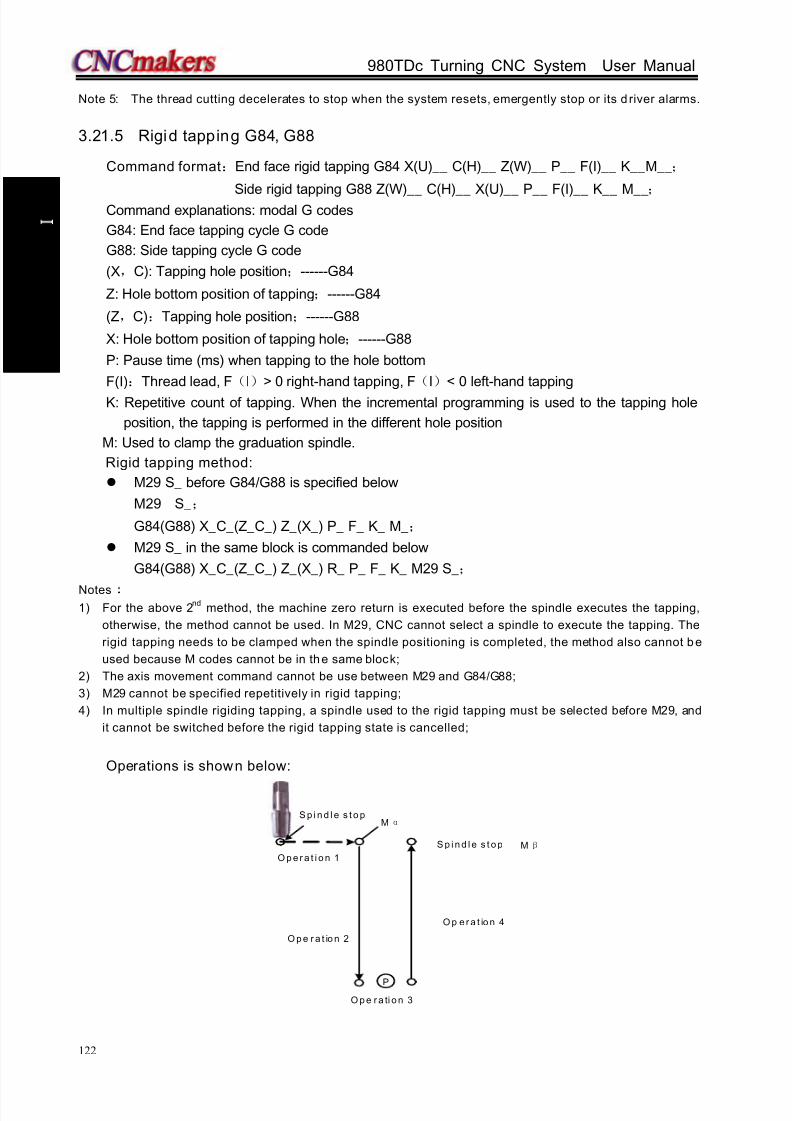
8/17/2019 980TDc CNC Turning Controller User Manual
http://slidepdf.com/reader/full/980tdc-cnc-turning-controller-user-manual 137/461
GSK980TDc Turning CNC System User Manual
122
P r o gr ammi n g
Note 5: The thread cutting decelerates to stop when the system resets, emergently stop or its d river alarms.
3.21.5 Rigid tapping G84, G88
Command format:End face rigid tapping G84 X(U)__ C(H)__ Z(W)__ P__ F(I)__ K__M__;
Side rigid tapping G88 Z(W)__ C(H)__ X(U)__ P__ F(I)__ K__ M__;
Command explanations: modal G codes
G84: End face tapping cycle G code
G88: Side tapping cycle G code
(X,C): Tapping hole position;------G84
Z: Hole bottom position of tapping;------G84
(Z,C):Tapping hole position;------G88
X: Hole bottom position of tapping hole;------G88
P: Pause time (ms) when tapping to the hole bottom
F(I):Thread lead, F(I)> 0 right-hand tapping, F(I)< 0 left-hand tapping
K: Repetitive count of tapping. When the incremental programming is used to the tapping hole
position, the tapping is performed in the different hole position
M: Used to clamp the graduation spindle.
Rigid tapping method:
M29 S_ before G84/G88 is specified below
M29 S_;
G84(G88) X_C_(Z_C_) Z_(X_) P_ F_ K_ M_;
M29 S_ in the same block is commanded below
G84(G88) X_C_(Z_C_) Z_(X_) R_ P_ F_ K_ M29 S_;
Notes1) For the above 2
nd method, the machine zero return is executed before the spindle executes the tapping,
otherwise, the method cannot be used. In M29, CNC cannot select a spindle to execute the tapping. The
rigid tapping needs to be clamped when the spindle positioning is completed, the method also cannot be
used because M codes cannot be in the same block;
2) The axis movement command cannot be use between M29 and G84/G88;
3) M29 cannot be specified repetitively in rigid tapping;
4) In multiple spindle rigiding tapping, a spindle used to the rigid tapping must be selected before M29, and
it cannot be switched before the rigid tapping state is cancelled;
Operations is shown below:
S p i n d l e s t o p
P
O p e r a t io n 2
O p e r a t i o n 1
O p e r a ti o n 3
O p e r a t io n 4
M α
S p i n d l e s t o p M β

8/17/2019 980TDc CNC Turning Controller User Manual
http://slidepdf.com/reader/full/980tdc-cnc-turning-controller-user-manual 138/461
Chapter 3 G Commands
123
P r o gr ammi n g
Execution explanations:
Operation 1:positioning to the hole position(starting point of rigid tapping);
Before starting operation 2, the system outputs Mα when it has M code used to clamp the
spindle;
Operation 2:start the rigid tapping;
Operation 3:pause time P in rigid tapping in hole bottom;
Operation 4:the rigid tapping returns to the hole bottom(starting point of rigid tapping;
When the block for rigid tapping specifies M code used to clamp the spindle, Mβ is output.
Note: α value is set in 170, β=
α
1, so, these corresponding M codes in PLC are executed.
Rigid tapping sequence
Taking example of G84 right-hand tapping, explain the creation, execution and cancellation of
rigid tapping.
Creation and execution of rigid tapping
The spindle rotation operation is defined that the rotary axis is switched to the position control
mode(i.e. send the position mode switch signal to the servo spindle), and the system checks the
position mode arrival signal of the servo spindle.
Rigid tapping cancellation
The cancellation methods of rigid tapping are shown below:
1) G80 cancels the rigid tapping mode;
2) G codes commands other cycles;
3) Other G codes in Group 01;
4) CNC resets.
The falling edge of F76.3 signal cancels the rigid tapping mode signal.
(a) RTCRG(186#2) is set to ‘1’ when:
The system executes directly the next block instead of waiting the rigid tapping mode signal
RGTAP<G61#0> to become ‘0’.

8/17/2019 980TDc CNC Turning Controller User Manual
http://slidepdf.com/reader/full/980tdc-cnc-turning-controller-user-manual 139/461
GSK980TDc Turning CNC System User Manual
124
P r o gr ammi n g
Rigid tapping cancellation is shown below:
(b) RTCRG(186#2) is set to ‘0’ when:
Wait the rigid tapping mode signal RGTAP<G61#0> to become ‘0’ and then execute the next
block. Rigid tapping cancellation is shown below:
Notes:
In rigid tapping, when the tapping direction is changed(i.e. G84 and G88 are switched),the
system specifies again the hole bottom position of the tapping, otherwise, the unexpectedresult rises;
The rigid tapping G command is in Group 01, it is cancelled temporarily in the rigid tapping
state, and then is recovered it after the tapping is done;
The dry run function is disabled in rigid tapping;
In the rigid tapping, the machine lock function is valid; the tapping axis and the spindle do not
move when the machine lock function is enabled;
When the reset is executed in the rigid tapping, the rigid tapping state is released and the
spindle returns to the previous state before the rigid tapping;
In rigid tapping, when the tapping block is executed and the tapping returns, the feed
hold/single block run function is disabled temporarily till the tapping return completes; In rigid tapping mode, the backlash compensation is performed to compensate the dry run of
the spindle rotation(CW, CCW). It is set in parameters (33~34 or 180~182). The
backlash compensation along the tapping axis is performed in general method;
In multiple spindle tapping, the 1st spindle is used to the graduation and the 2nd to the tapping.
After the 1st spindle graduation is completed, the spindle must be clamped on the machine
and the machine clamping/releasing M code can be specified in the rigid tapping. M code
used to clamp the spindle is added in G84/G88, i.e. the system can output two kinds of M
code. M code used to clamp the spindle is set in the data parameter (170). M code used to
the releasing is the setting value +1 of 170;
Setting RTORI(state parameter 186#7)to 1 can execute the reference point return of the
spindle before the system starts the rigid tapping.

8/17/2019 980TDc CNC Turning Controller User Manual
http://slidepdf.com/reader/full/980tdc-cnc-turning-controller-user-manual 140/461
Chapter 3 G Commands
125
P r o gr ammi n g
3.21.6 Thread cut ting cycle G92
Command format: G92 X(U) _ Z(W) _ F_ J_ K_ L ; (Metric straight thread cutting cycle)
G92 X(U) _ Z(W) _ I_ J_ K_ L ; (Inch straight thread cutting cycle)
G92 X(U) _ Z(W) _ R_ F_ J_ K_ L ; (Metric taper thread cutting cycle)
G92 X(U) _ Z(W) _ R_ I_ J_ K_ L ; (Metric taper thread cutting cycle)Command function: Tool infeeds in radial(X) direction and cuts in axial(Z or X, Z) direction from
starting point of cutting to realize straight thread, taper thread cutting cycle with
constant thread pitch. Thread run-out in G92: at the fixed distance from end
point of thread cutting, Z executes thread interpolation and X retracts with
exponential or linear acceleration, and X retracts at rapidly traverse speed after
Z reaches to end point of cutting as Fig. 3-44.
Command specifications:
G92 is modal;
Starting point of cutting: starting position of thread interpolation;
End point of cutting: end position of thread interpolation;X: X absolute coordinate of end point of cutting, unit: mm;
U: different value of X absolute coordinate from end point to starting point of cutting, unit: mm;
Z: Z absolute coordinate of end point of cutting, unit: mm;
W: Different value of X absolute coordinate from end point to starting point of cutting, unit: mm;
R: Different value(radius value) of X absolute coordinate from end point to starting point of cutting.
When the sign of R is not the same that of U, R≤U/2, unit: mm;
F: Thread lead, its range: 0< F ≤500 mm. After F value is executed, it is reserved and can be
omitted;
I: Thread teeth per inch, its range: 0.06tooth/inch~25400tooth/inch , it is reserved and it can be
omitted not to input after I specified value is executed;
J: Movement in the short axis in thread run-out, its range 0~99999999× least input increment ,
unit: mm/inch, without direction ( automatically define its direction according to starting position
of program), and it is modal parameter. If the short axis is X, its value is specified by radius;
K: Movement in the long axis in thread run-out, its range: 0~99999999× least input increment ,
unit: mm/inch, without direction ( automatically define its direction according to starting position
of program), and it is modal parameter. If the long axis is X, its value is specified by radius;
L: Multi threads: 1~99 and it is modal parameter. (The system defaults it is single thread when L
is omitted).
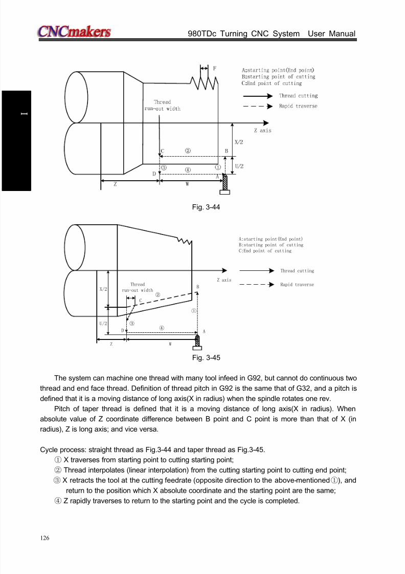
8/17/2019 980TDc CNC Turning Controller User Manual
http://slidepdf.com/reader/full/980tdc-cnc-turning-controller-user-manual 141/461
GSK980TDc Turning CNC System User Manual
126
P r o gr ammi n g
Fig. 3-44
Z W
④
Z axisThread
run-out width
A
①
②
③
B
C
D
X/2Rapid traverse
Thread cutting
A:starting point(End point)B:starting point of cuttingC:End point of cutting
U/2
Fig. 3-45
The system can machine one thread with many tool infeed in G92, but cannot do continuous two
thread and end face thread. Definition of thread pitch in G92 is the same that of G32, and a pitch is
defined that it is a moving distance of long axis(X in radius) when the spindle rotates one rev.Pitch of taper thread is defined that it is a moving distance of long axis(X in radius). When
absolute value of Z coordinate difference between B point and C point is more than that of X (in
radius), Z is long axis; and vice versa.
Cycle process: straight thread as Fig.3-44 and taper thread as Fig.3-45.
① X traverses from starting point to cutting starting point;
② Thread interpolates (linear interpolation) from the cutting starting point to cutting end point;
③ X retracts the tool at the cutting feedrate (opposite direction to the above-mentioned ①), and
return to the position which X absolute coordinate and the starting point are the same;
④ Z rapidly traverses to return to the starting point and the cycle is completed.

8/17/2019 980TDc CNC Turning Controller User Manual
http://slidepdf.com/reader/full/980tdc-cnc-turning-controller-user-manual 142/461
Chapter 3 G Commands
127
P r o gr ammi n g
Notes:
Length of thread run-out is specified by 019 when J, K are omitted;
Length of thread run-out is K in the long direction and is specified by 019 when J is
omitted;
Length of thread run-out is J=K when K is omitted;
There is no thread run-out when J=0 or J=0, K=0;
Length of thread run-out is J=K when J≠0,K=0;
There is no thread run-out when J=0,K≠0;
After executing the feed hold in thread cutting, the system does not stop cutting until the
thread cutting is completed with Pause on screen;
After executing single block in thread cutting, the program run stops after the system
returns to starting point(one thread cutting cycle is completed);
They are executed as the positive values when J, K negative values are input;
Thread cutting decelerates to stop when the system resets, emergently stops or its driver
alarms. Command path: relative position between thread cutting end point and starting point with U, W, R
and tool path and thread run-out direction with different U, W, R signs below:
Fig.3-46
1) U>0,W<0,R>0 2) U<0,W<0,R<0
W
U/2 ③ ①
②
④ R
WZ
X
Z
X
①
②
③
④
U/2
R
J
K
J
K
3) U>0,W>0,R<0 ,R≤U/2 4) U<0,W>0,R>0,R≤U/2
④
R
W
U/2③
②
①
Z
X
R
W
U/2
②
①
④
③
Z
X
JK
J
K

8/17/2019 980TDc CNC Turning Controller User Manual
http://slidepdf.com/reader/full/980tdc-cnc-turning-controller-user-manual 143/461
GSK980TDc Turning CNC System User Manual
128
P r o gr ammi n g
Example:Fig.3-47
Fig.3-47Program:
O0012;
M3 S300 G0 X150 Z50 T0101; (Thread tool)
G0 X65 Z5; (Rapid traverse)
G92 X58.7 Z-28 F3 J3 K1; (Machine thread with 4 times cutting, the first tool infeed
1.3mm)
X57.7 ; (The second tool infeed 1mm)
X57; (The third tool infeed 0.7mm)
X56.9; (The fourth tool infeed 0.1mm)
M30;
3.21.7 Multip le thread cutting cycle G76
Command format: G76 P(m) (r) (a) Q(dmin) R(d) ;G76 X(U) Z(W) R(i) P(k) Q( d) F(I) ;
Command function: Machining thread with specified depth of thread (total cutting depth)is
completed by multiple roughing and finishing, if the defined angle of
thread is not 0°, thread run-in path of roughing is from its top to bottom,
and angle of neighboring thread teeth is the defined angle of thread. G76
can be used for machining the straight and taper thread with thread
run-out path, which is contributed to thread cutting with single tool edge to
reduce the wear of tool and to improve the precision of machining thread.
But G76 cannot be used for machining the face thread. machining path is
shown in Fig. 3-48(a): Relevant definitions:
Starting point(end po int): Position before block runs and behind blocks run, defined by A point;
End point of thread(D point): End point of thread cutting defined by X(U) Z(W) .The tool
will not reach the point in cutting if there is the thread run-out path;
Starting point of thread: Its absolute coordinates is the same that of A point and the different
value of X absolute coordinates between C and D is i(thread taper with radius value). The tool
cannot reach C point in cutting when the defined angle of thread is not 0°;
Reference point of thread cut ting depth (B point) : Its absolute coordinates is the same that
of A point and the different value of X absolute coordinate between B and C is k(thread taper with
radius value).The cutting depth of thread at B point is 0 which is the reference point used for
counting each thread cutting depth by the system;
Thread cutting depth: It is the cutting depth for each thread cutting cycle. It is the different value

8/17/2019 980TDc CNC Turning Controller User Manual
http://slidepdf.com/reader/full/980tdc-cnc-turning-controller-user-manual 144/461
Chapter 3 G Commands
129
P r o gr ammi n g
(radius value, without signs) of X absolute coordinate between B and intersection of reversal
extension line for each thread cutting path and straight line BC. The cutting depth for each
roughing is n ×d, n is the current roughing cycle times, d is the thread cutting depth of first
roughing;
Thread cutting amount: Different value between the current thread current depth and theprevious one:( 1nn −− ) ×d;
End point of tool retraction: It is the end position of radial (X) tool retraction after the thread
cutting in each thread roughing, finishing cycle is completed, defining with E point;
Thread cut-in point: Bn (n is the cutting cycle times) is the actual thread cutting starting point in
each thread roughing cycle and finishing cycle, B1 is the first thread roughing cutting-in point, Bf is
the last thread roughing cut-in point, Be is the thread finishing cutting-in point. Bn is X, Z
replacement formula corresponding to B.
α Z replacement2 X replacement
tga:thread angle;
X: X absolute coordinate (unit: mm) of thread end point;
U: Different value (unit: mm) of X absolute coordinate between thread end point and starting point;
Z: Z absolute coordinate (unit: mm) of thread end point;
W: Different value (unit: mm) of Z absolute coordinate between thread end point and starting point;
P(m): Times of thread finishing: 00~99 (unit: times). It is valid after m specified value is executed,
and the system parameter 057 value is rewritten to m. The value of system parameter 057 is
regarded as finishing times when m is not input. In thread finishing, every feed cutting amount is
equal to the cutting amount d in thread finishing dividing the finishing times m;
P(r): Width of thread run-out 00~99(unit: 0.1×L,L is the thread pitch). It is valid after r specified value
is executed and the system parameter 019 value is rewritten to r. The value of system parameter
019 is the width of thread run-out when r is not input. The thread run-out function can be applied to
thread machining without tool retraction groove and the width of thread run-out defined by system
parameter 019 is valid for G92, G76;
P(a): Angles at taper of neighboring two tooth,range: 00~99,unit:deg(°). It is valid after a specified
value is executed and the system parameter 058 value is rewritten to a. The system parameter
058 value is regarded as angle of thread tooth. The actual angle of thread in defined by tool ones
and so a should be the same as the tool angle;
Q( dmin): Minimum cutting travel of t hread roughing, range: 0 ~ 999999( IS-C)/ 0 ~
99999( IS-B),(unit: least input increment, radius value). When ( 1nn −− ) × d < dmin, dmin
is regarded as the cutting travel of current roughing, i.e. depth of current thread cutting is
( 1n − × d+ dmin) . Setting dmin is to avoid the too small of roughing amount and too many
roughing times caused by the cutting amount deceleration in thread roughing. After Q( dmin) is
executed, the specified value dmin is valid and the system data parameter NO. 059 value is
rewritten to dmin (unit: 0.001). w hen Q( dmin) is not input, the system data parameter NO.059
value is taken as the least cutting amount;
R(d): It is the cutting amount in thread finishing, range: 00~99.999 (unit: mm/inch, radius value
without sign symbols), the radius value is equal to X absolute coordinates between cut-in point Be of
thread finishing and Bf of thread roughing. After R(d) is executed, the specified value d is reservedand the system parameter 060 value is rewritten to d×1000(unit: 0.001 mm) . The value of system
parameter 060 is regarded as the cutting travel of thread finishing when R(d) is not input;

8/17/2019 980TDc CNC Turning Controller User Manual
http://slidepdf.com/reader/full/980tdc-cnc-turning-controller-user-manual 145/461
GSK980TDc Turning CNC System User Manual
130
P r o gr ammi n g
R(i): It is thread taper and is the different value of X absolute coordinate between thread starting
point and end point, rang: -99999.999~99999.999(IS_B)/-9999.9999~9999.9999(IS_C) (unit::
mm/inch, radius value). The system defaults R(i)=0(straight thread) when R(i) is not input;
P(k): Depth of thread tooth, the total cutting depth of thread, range: 1~99999999(unit: least input
increment, radius value, without sign symbols). The system alarms when P(k) is not input;
Q( d): Depth of the 1st thread cutting, range: 1~99999999 unit: least input increment, radius
value, without sign symbols). The system alarms when d is not input;
F: metric thread pitch, its range is referred to Table 1-2;
I: thread teeth per inch for inch thread, its range is referred to Table 1-2.
J:movement amount (run-out amount) (unit: mm/inch, without direction) in the short axis when
thread run-out; when the short axis is X, its value is designated by radius and is simple
parameter;
K:movement amount (run-out amount) (unit: mm/inch, without direction) in the long axis when
thread run-out; when the long axis is X, its value is designated by radius and is simple
parameter.
Note: J, K are not compi led in G76, its thread run-out method is the same that of the previous, i.e. the thread
run-out i s executed according to P® or No.19; when J or, K, or J, K are compiled, the thread run-out
method is the same those of G32, G92.
X
a x
i s
B1Bn
Bf
Z W
X/2
Z axis
Rapid traverse
Thread cutting
A:Starting point(End point)B:Reference point of thread
cutting depthC:Starting point of thread cuttingD:End point of thread cutting
Be
r
i
D
U/2
C
a/2
A
d
d√n
k
d
E
Fig. 3-48(a)
Cut-in method as follows: Fig. 3-48(b):

8/17/2019 980TDc CNC Turning Controller User Manual
http://slidepdf.com/reader/full/980tdc-cnc-turning-controller-user-manual 146/461
Chapter 3 G Commands
131
P r o gr ammi n g
Fig. 3-48(b)
Pitch is defined to moving distance ( X radius value) of long axis when the spindle rotates one rev.Z is long when absolute value of coordinate difference between C point and D point in Z direction is
more than that of X direction ( radius value, be equal to absolute value of i); and vice versa
Execution process:
① The tool rapidly traverses to B1, and the thread cutting depth is d. The tool only
traverses in X direction when a=0; the tool traverses in X and Z direction and its
direction is the same that of A→D when a≠0;
② The tool cuts threads paralleling with C→D to the intersection of D→E (r ≠0: thread
run-out);
③ The tool rapidly traverses to E point in X direction;
④
The tool rapidly traverses to A point in Z direction and the single roughing cycle is
completed;
⑤ The tool rapidly traverses again to tool infeed to Bn ( is the roughing times), the cutting
depth is the bigger value of ( n ×d) ,( 1-n ×d+dmin) , and execute ② if the
cutting depth is less than(k-d) ; if the cutting depth is more than or equal to(k-d) , the tool
infeeds(k-d) to Bf , and then execute ⑥ to complete the last thread roughing;
⑥ The tool cuts threads paralleling with C→D to the intersection of D→E (r ≠0: thread
run-out);
⑦ X axis rapidly traverses to E point;
⑧
Z axis traverses to A point and the thread roughing cycle is completed to execute thefinishing;
⑨ After the tool rapidly traverses to B(the cutting depth is k and the cutting travel is d),
execute the thread finishing, at last the tool returns to A point and so the thread finishing
cycle is completed;
⑩ If the finishing cycle time is less than m, execute ⑨ to perform the finishing cycle, the
thread cutting depth is k and the cutting travel is 0; if the finishing cycle times are equal
to m, G76 compound thread machining cycle is completed.
Notes:
In thread cutting, execute the feed hold, the system displays Pause after the thread
cutting is executed completely, and then the program run pauses; Execute single block in thread cutting, the program run stops after returning to starting
point(one thread cutting cycle is completed);
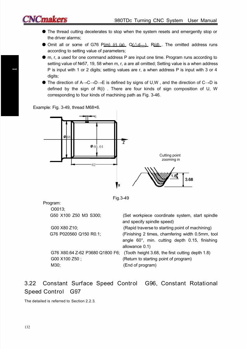
8/17/2019 980TDc CNC Turning Controller User Manual
http://slidepdf.com/reader/full/980tdc-cnc-turning-controller-user-manual 147/461
GSK980TDc Turning CNC System User Manual
132
P r o gr ammi n g
The thread cutting decelerates to stop when the system resets and emergently stop or
the driver alarms;
Omit all or some of G76 P(m) (r) (a) Q(dmin) R(d) . The omitted address runs
according to setting value of parameters;
m, r, a used for one command address P are input one time. Program runs according to
setting value of 57, 19, 58 when m, r, a are all omitted; Setting value is a when address
P is input with 1 or 2 digits; setting values are r, a when address P is input with 3 or 4
digits;
The direction of A→C→D→E is defined by signs of U,W , and the direction of C→D is
defined by the sign of R(i) . There are four kinds of sign composition of U, W
corresponding to four kinds of machining path as Fig. 3-46.
Example: Fig. 3-49, thread M68×6.
6
60.64
68
62
Fig.3-49Program:
O0013;
G50 X100 Z50 M3 S300; (Set workpiece coordinate system, start spindle
and specify spindle speed)
G00 X80 Z10; (Rapid traverse to starting point of machining)
G76 P020560 Q150 R0.1; (Finishing 2 times, chamfering width 0.5mm, tool
angle 60°, min. cutting depth 0.15, finishing
allowance 0.1)
G76 X60.64 Z-62 P3680 Q1800 F6; (Tooth height 3.68, the first cutting depth 1.8)
G00 X100 Z50 ; (Return to starting point of program)
M30; (End of program)
3.22 Constant Surface Speed Control G96, Constant Rotational
Speed Control G97
The detailed is referred to Section 2.2.3.
Cutting pointzooming in

8/17/2019 980TDc CNC Turning Controller User Manual
http://slidepdf.com/reader/full/980tdc-cnc-turning-controller-user-manual 148/461
Chapter 3 G Commands
133
P r o gr ammi n g
3.23 Feedrate per Minute G98, Feedrate per Rev G99
Command format: G98 F_; (its range is referred to Section 1.6.5, the leading zero can be
omitted, feed rate per minute is specified, mm/min)
Command function: cutting feed rate is specified as mm/min, G98 is the modal G command.
G98 cannot be input if the current command is G98 modal.Command format: G99 F_; (its range is referred to Section 1.6.5, the leading zero can be
omitted)
Command function: Cutting feed rate is specified as mm/min, G99 is the modal G command.
G99 input may be omitted if current state is G99. The actual cutting
feedrate is gotten by multiplying the F command value (mm/r) to the
current spindle speed(r/min). If the spindle speed varies, the actual
feedrate changes too. If the spindle cutting feed amount per rev is
specified by G99 FXXXX , the even cutting texture on the surface of
workpiece will be gotten. In G99 state, a spindle encoder should be fixed
on the machine tool to machine the workpiece.G98, G99 are the modal G commands in the same group and only one is valid. G98 is the initial state
G command and the system defaults G98 is valid when the system turns on.
Reduction formula of feed between per rev and per min:
Fm = Fr ×S
Fm: feed per min (mm/min) ;
Fr : feed per rev (mm/r) ;
S: spindle speed (r/min) .
After the system turns on, the feedrate is ones set by 030 and F value is reserved after F is
executed. The feed rate is 0 after F0 is executed. F value is reserved when the system resets and
emergently stops. The feedrate override is reserved when the system is turned off.
Note: In G99 modal, there is the uneven cutting feed rate when the spindle speed is lower than 1 r/min; there
is the follow error in the actual cutting feed rate when there is the swing in the spindle speed. To gain
the high machining qualit y, it is recommended that the selected spindle speed should be not lower
than min. speed of spindle servo or converter.
Cutting feed: The system can control the motions in X, Z direction contributed that the motion path of
tool and the defined path by commands (line straight, arc ) is consistent, and also
instantaneous speed on the tangent of motion path and F word is consistent, which
motion control is called cutting feed or interpolation. The cutting feedrate is specified by
F, the system divides the cutting feedrate specified by F according to the programmingpath into vector in X, Z direction, also controls the instantaneous speed in X, Z direction
to contribute that the combined speed of vector in X, Z direction is equal to F command
value.
Example: In Fig. 2-101, the data in the brackets are the coordinates for each point (it is thediameter in X axis), the system parameter No.022 is 3800, the system parameter
No.023 is 7600, the rapid override and feedrate override are 100%.
2 2
2 2
x x
x z
z z
x z
d f F
d d
d f F
d d
= •
+
= •
+
F is the combined speed of vector of X/Y-axis instantaneous speed;dx is the X-axis instantaneous(dt) increment,f x is the X-aixs instantaneous speed in X direction;dz is the Z-axis instantaneous(dt) increment ,f z is the Z-axis instantaneous speed.

8/17/2019 980TDc CNC Turning Controller User Manual
http://slidepdf.com/reader/full/980tdc-cnc-turning-controller-user-manual 149/461
GSK980TDc Turning CNC System User Manual
134
P r o gr ammi n g
Fig. 3-50
Program as follows:
G50 X160 Z80; (Create a workpiece coordinate system)G0 G98 X50 Z0; (Rapid traverse from A to B through M point. A→M: X-axis rapid traverse
speed 7600mm/min, Z-axis 7600mm/min in Z direction, M→B: X-axis
rapid traverse
speed 0mm/min, Z-axis 7600mm/min in Z direction
G1 W-30 F100; (B→C, X-axis rapid traverse speed 0mm/min, Z-axis 100mm/min)
X100 W-20; (C→D, X-axis rapid traverse speed 156mm/min, Z-axis 62mm/min)
X140; (D→E, X-axis rapid traverse speed 200mm/min, Z-axis 0mm/min)
G3 W-100 R20; (EFG circular interpolation, E point: X axis instantaneous speed 200mm/min,
Z axis 0mm/min
F point: X-axis instantaneous speed 0mm/min,Z axis 100mm/min)
W-10; (G→H, X axis rapid traverse speed 0 mm/min, Z axis 100mm/min)
M30;
The system supplies 16 steps for spindle override (0%~150%, increment of 10%).PLC ladder
defines tune ways of spindle override and whether the actual feedrate override steps is reserved or
not after the system is switched off, which is referred by user manual from machine manufacturer
when using the system. Refer to the following functions of GSK980TDc standard PLC ladder.
The cutting feedrate can be tuned real time by the feedrate override key on the operator panel or
the external override switch, and the actual cutting feedrate is tuned at 16 steps in 0~150%
(increment of 10%) but it is invalid for thread cutting to tune the feedrate override. Refer to
OPERATION about cutting feedrate override.
Related parameters:
System parameter No.027: the upper limit value of cutting feedrate(they are the same in X, Z
direction, diameter/min in X direction);
System parameter No.029: exponential function for time constant of acceleration/deceleration
when cutting feed and manual feed;
System parameter No.030: initial (ultimate) speed of acceleration/deceleration in exponential
function when cutting feed and manual feed.
x
z
A Starting point
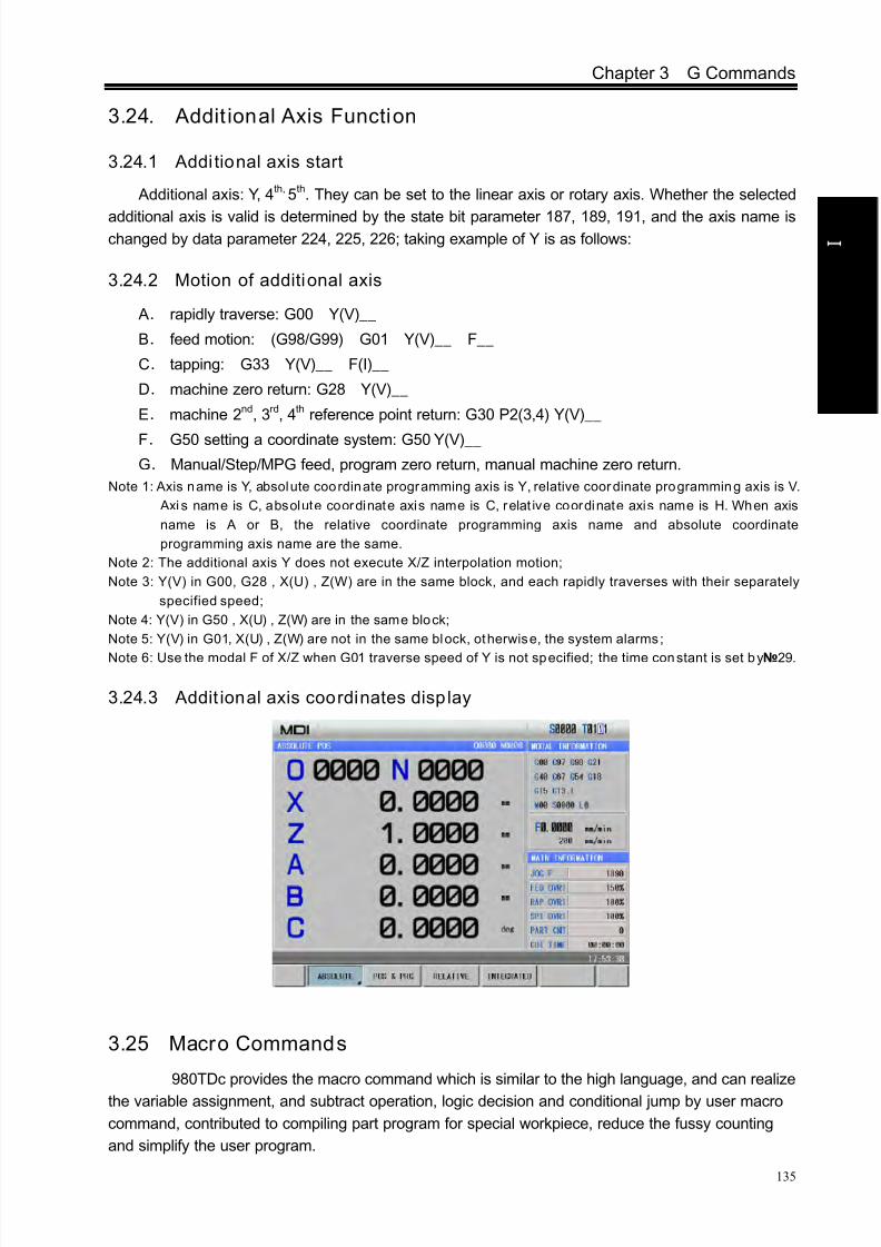
8/17/2019 980TDc CNC Turning Controller User Manual
http://slidepdf.com/reader/full/980tdc-cnc-turning-controller-user-manual 150/461
Chapter 3 G Commands
135
P r o gr ammi n g
3.24. Addit ional Axis Function
3.24.1 Additional axis start
Additional axis: Y, 4th, 5th. They can be set to the linear axis or rotary axis. Whether the selected
additional axis is valid is determined by the state bit parameter 187, 189, 191, and the axis name ischanged by data parameter 224, 225, 226; taking example of Y is as follows:
3.24.2 Motion of additional axis
A. rapidly traverse: G00 Y(V)__
B. feed motion: (G98/G99) G01 Y(V)__ F__
C. tapping: G33 Y(V)__ F(I)__
D. machine zero return: G28 Y(V)__
E. machine 2nd, 3rd, 4th reference point return: G30 P2(3,4) Y(V)__
F. G50 setting a coordinate system: G50 Y(V)__
G. Manual/Step/MPG feed, program zero return, manual machine zero return.
Note 1: Axis name is Y, absolute coordinate programming axis is Y, relative coordinate programming axis is V.
Axi s name is C, absolute coordinate axis name is C, relat ive coordinate axis name is H. When axis
name is A or B, the relative coordinate programming axis name and absolute coordinate
programming axis name are the same.
Note 2: The additional axis Y does not execute X/Z interpolation motion;
Note 3: Y(V) in G00, G28 , X(U) , Z(W) are in the same block, and each rapidly traverses with their separately
specified speed;
Note 4: Y(V) in G50 , X(U) , Z(W) are in the same block;
Note 5: Y(V) in G01, X(U) , Z(W) are not in the same block, otherwise, the system alarms;
Note 6: Use the modal F of X/Z when G01 traverse speed of Y is not specified; the time constant is set by 29.
3.24.3 Addit ional axis coordinates disp lay
3.25 Macro Commands
GSK980TDc provides the macro command which is similar to the high language, and can realize
the variable assignment, and subtract operation, logic decision and conditional jump by user macro
command, contributed to compiling part program for special workpiece, reduce the fussy counting
and simplify the user program.
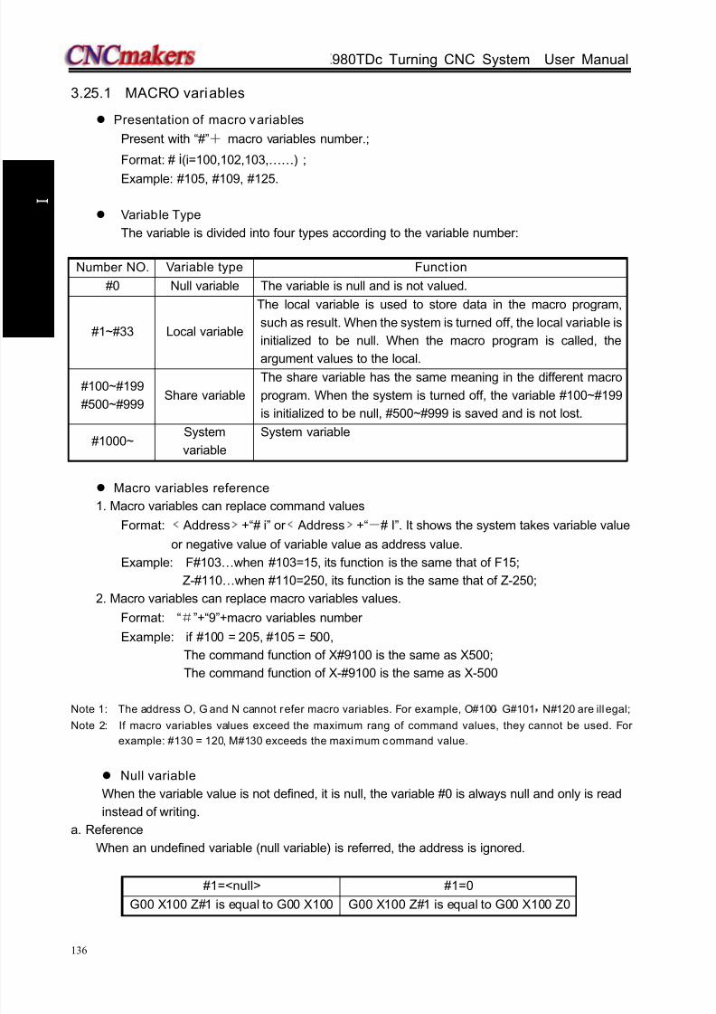
8/17/2019 980TDc CNC Turning Controller User Manual
http://slidepdf.com/reader/full/980tdc-cnc-turning-controller-user-manual 151/461
GSK980TDc Turning CNC System User Manual
136
P r o gr ammi n g
3.25.1 MACRO variables
Presentation of macro variables
Present with “#”+ macro variables number.;
Format: # i(i=100,102,103,……) ;
Example: #105, #109, #125.
Variable Type
The variable is divided into four types according to the variable number:
Number NO. Variable type Funct ion
#0 Null variable The variable is null and is not valued.
#1~#33 Local variable
The local variable is used to store data in the macro program,
such as result. When the system is turned off, the local variable is
initialized to be null. When the macro program is called, the
argument values to the local.
#100~#199
#500~#999Share variable
The share variable has the same meaning in the different macro
program. When the system is turned off, the variable #100~#199
is initialized to be null, #500~#999 is saved and is not lost.
#1000~System
variable
System variable
Macro variables reference
1. Macro variables can replace command values
Format: ﹤ Address﹥+“# i” or ﹤ Address﹥+“-# I”. It shows the system takes variable value
or negative value of variable value as address value.
Example: F#103…when #103=15, its function is the same that of F15;
Z-#110…when #110=250, its function is the same that of Z-250;
2. Macro variables can replace macro variables values.
Format: “#”+“9”+macro variables number
Example: if #100 = 205, #105 = 500,
The command function of X#9100 is the same as X500;
The command function of X-#9100 is the same as X-500
Note 1: The address O, G and N cannot refer macro variables. For example, O#100,
G#101,
N#120 are illegal;Note 2: If macro variables values exceed the maximum rang of command values, they cannot be used. For
example: #130 = 120, M#130 exceeds the maximum command value.
Null variable
When the variable value is not defined, it is null, the variable #0 is always null and only is read
instead of writing.
a. Reference
When an undefined variable (null variable) is referred, the address is ignored.
#1=<null> #1=0G00 X100 Z#1 is equal to G00 X100 G00 X100 Z#1 is equal to G00 X100 Z0

8/17/2019 980TDc CNC Turning Controller User Manual
http://slidepdf.com/reader/full/980tdc-cnc-turning-controller-user-manual 152/461
Chapter 3 G Commands
137
P r o gr ammi n g
b. Operation
Except for using <null variable > to value, the <null variable> used to operation in other
conditions is the same as that of “0”.
#1=<null> #1=0
#2=#1
↓(execution result)
#2=<null>
#2=#1
↓(execution result)
#2=0
#2=#1﹡5
↓(execution result)
#2=0
#2=#1﹡5
↓(execution result)
#2=0
#2=#1+#1
↓(execution result)
#2=0
#2=#1+#1
↓(execution result)
#2=0
c. Condition expression
<null>s in EQ(=) & NE(≠) are different to “0”.
#1=<null> #1=0
#1 EQ #0
↓
Valid
#1 EQ #0
↓ Invalid
#1 NE #0
↓
Invalid
#1 NE #0
↓
Invalid#1 GE #0
↓
Valid
#1 GE #0
↓
Invalid
#1 GT #0
↓
Invalid
#1 GT #0
↓
Invalid
Variable display

8/17/2019 980TDc CNC Turning Controller User Manual
http://slidepdf.com/reader/full/980tdc-cnc-turning-controller-user-manual 153/461
GSK980TDc Turning CNC System User Manual
138
P r o gr ammi n g
(1) In macro window, the variable being displayed to the null means it is null, i.e. it is not
defined. The variable being displayed to “********” means it exceeds the displayable
range.
(2) The share variable (#100~#199, #500~#999) values are displayed in the macro variable
window, and is also displayed the window, the data is input directly to value the share
variable.
(3) The local variable (#1~#33) and the system variable values are not displayed. Some
local variable or system variable value is displayed by assigned with the share variable.
System variable
(1)Interface signal: CNC only executes G and F signals. Whether there are I/O to correspond
to it is defined by PLC.
Variable No. Function
#1000~#1015
#1032
Correspond G54.0~G54.7, G55.0~G55.7 signal states
Correspond G54, G55 signal states#1100~#1115
#1132
Correspond F54.0~G54.7, F55.0~F55.7 signal states
Correspond F54, F55 signal states
#1133 Correspond F56, F57, F58, F59 signal states
(2) Tool compensation system variable:
Compensation
No.
X compensation
value
Z compensation
value
Tool tip radius
compensation valueImagery
tool tip
position T
Y compensation
value
WearGeometric
shapeWear
Geometric
shapeWear
Geometric
shapeWear
Geometric
shape
1…
32
#2001…
#2032
#2701…
#2732
#2101…
#2132
#2801…
#2832
#2201…
#2232
#2901…
#2932
#2301…
#2332
#2401…
#2432
#2451…
#2482
(3) Machined workpiece number:
Variable No. Function
#3901 Machined workpiece number(completion)
(4) System modal information variable
Variable
No. Function
#4001
G00, G01, G02, G03, G05, G32, G33, G34, G80,
G84, G88, G90, G92, G94, G124(G06.2),
G126(G06.3),G132(G32.1),G144(G07.2),G146(G07.3)
No. 1 group
#4002 G96, G97 No. 2 group
#4005 G98, G99 No. 3 group
#4006 G20, G21 No. 6 group
#4007 G40, G41, G42 No. 7 group
#4012 G66, G67 No. 12 group
#4013 G54,G55,G56,G57,G58,G59 No. 14 group#4016 G17,G18,G19 No. 16 group
#4109 F command

8/17/2019 980TDc CNC Turning Controller User Manual
http://slidepdf.com/reader/full/980tdc-cnc-turning-controller-user-manual 154/461
Chapter 3 G Commands
139
P r o gr ammi n g
#4113 M command
#4114 Serial No.
#4115 Program No.
#4119 S command
#4120 T command
(5) system variable of coordinate position information:
Variable No. Position signal Coordinate systemTool compensation
valueRead in running
#5001~#5005 End point of blockWorkpiece
coordinate systemNot including Possible
#5021~#5025 Current positionMachine
coordinate systemIncluding impossible
#5041~#5045 Current positionWorkpiece
coordinate system
Note: The posi tion listed in the above table separately cor responds orderly to X, Y, Z, 4
th, 5
th axis. For example:
#5001 meanings to be X position information, #5002 meanings to be Y position information, #5003
meanings to be Z position information and #5004 meanings to 4th
position information and #5005
meanings to 5th
position information.
(6)Compensation values of workpiece coordinate systems
Variable No. Function
#5201~#5205 External workpiece zero offset value of 1st ~5th axis
#5221~#5225 G54 workpiece zero offset value of 1st ~5th axis
#5241~#5245 G55 workpiece zero offset value of 1st ~5th axis
#5261~#5265 G56 workpiece zero offset value of 1st ~5th axis#5281~#5285 G57 workpiece zero offset value of 1st ~5th axis
#5301~#5305 G58 workpiece zero offset value of 1st ~5th axis
#5321~#5325 G59 workpiece zero offset value of 1st ~5th axis
Note: Message described in the above table separately corresponds to X, Y, Z, the 4th
, 5th
axis. For
example, #5201 means the offset message of X axis, #5202 means the one of Y axis,
#5203 means
the one of Z axis,#5204 means the one of the 4th axis, #5205 means the one of the 5th axis.
(7) Application:

8/17/2019 980TDc CNC Turning Controller User Manual
http://slidepdf.com/reader/full/980tdc-cnc-turning-controller-user-manual 155/461
GSK980TDc Turning CNC System User Manual
140
P r o gr ammi n g
O0100; (#100 is the machined workpiece number, its
initial value=0)
G00 X100 Z100;
T0101;
IF[#100<100]GOTO10; (has continuously machined
100?)
G65 P9580 U-0.01 W-0.01; (call the macro program
compensation tool wear)
N10 G00 X50 Z50;
……;
……;
……;
Machine program;
……;
T0202;IF[#100<100]GOTO20; (has continuously machined
100?)
G65 P9580 U-0.01 W-0.01; (call the macro program
compensation tool wear)
N20 ……;
……;
……;
#100=#100+1; (machined workpiece number +1)
IF[#100==101]THEN #100=0;
M30;
O9580;
G65 H23 P#101 Q#4120 R100; (obtain the
tool offset No.)
#102=2000+#101; (X wear macro
variable)
#103=2100+#101; (Z wear macro
variable)
#9102=#9102+#21; (modify X wear)
#9103=#9103+#23; (modify Z wear)
T#4120; (call a new tool offset value)
M99;
3.25.2 Operation and jump command G65
Command format:
G65 Hm P# i Q# j R# k;
m: operation or jump command, range 01~99.
# I: macro variables name for storing values.
# j: macro variables name 1 for operation, can be constant.
# k: macro variables name 2 for operation, can be constant.
Command significance: # i = #j O # k
Example: P#100 Q#101 R#102…..#100 = #101 O #102;
P#100 Q#101 R15….#100 = #101 O 15;
P#100 Q-100 R#102…..#100 = -100 O #102;
Note: Macro variable name has no “#” when it is presented directly with constant.
Macro command list
Command format Functions Definitions
G65 H01 P#i Q#j Assignment # i = # j assign value of j to iG65 H02 P#i Q#j R#k; Decimal add operation # i = # j + # k
G65 H03 P#i Q#j R#k; Decimal subtract operation # i = # j - # k
Operation sign specified by Hm

8/17/2019 980TDc CNC Turning Controller User Manual
http://slidepdf.com/reader/full/980tdc-cnc-turning-controller-user-manual 156/461
Chapter 3 G Commands
141
P r o gr ammi n g
Command format Functions Definitions
G65 H04 P#i Q#j R#k; Decimal multiplication operation # i = # j×# k
G65 H05 P#i Q#j R#k; Decimal division operation # i = # j÷# k
G65 H11 P#i Q#j R#k; Binary addition # i = # j OR # k
G65 H12 P#i Q#j R#k; Binary multiplication(operation) # i = # j AND # k
G65 H13 P#i Q#j R#k; Binary exclusive or # i = # j XOR # k
G65 H21 P#i Q#j; Decimal square root # i = j#
G65 H22 P#i Q#j; Decimal absolute value # i = |# j |
G65 H23 P#i Q#j R#k; Decimal remainder Remainder of # i = (#j÷# k)
G65 H24 P#i Q#j; Decimal into binary # i = BIN(# j )
G65 H25 P#i Q#j; Binary into decimal # i = DEC(# j )
G65 H26 P#i Q#j R#k;Decimal multiplication/division
operation
# i = # i×# j÷# k
G65 H27 P#i Q#j R#k; Compound square root # i =22
## k j +
G65 H31 P#i Q#j R#k; Sine # i = # j×sin(# k)
G65 H32 P#i Q#j R#k; Cosine # i = # j×cos(# k)
G65 H33 P#i Q#j R#k; Tangent # i = # j×tan(# k)
G65 H34 P#i Q#j R#k; Arc tangent # i = ATAN(# j / # k)
G65 H80 Pn; Unconditional jump Jump to block n
G65 H81 Pn Q#j R#k; Conditional jump 1Jump to block n if # j = # k,otherwise
the system executes in order
G65 H82 Pn Q#j R#k; Conditional jump 2Jump to block n if # j ≠ # k, otherwise
the system executes in order
G65 H83 Pn Q#j R#k; Conditional jump 3
Jump to block n if # j ﹥ # k,
otherwise the system executes in
order
G65 H84 Pn Q#j R#k; Conditional jump 4
Jump to block n if # j ﹤ # k,
otherwise the system executes in
order
G65 H85 Pn Q#j R#k; Conditional jump 5Jump to block n if # j ≥ # k, otherwise
the system executes in order
G65 H86 Pn Q#j R#k; Conditional jump 6
Jump to block n if # j ≤# k, otherwise
the system executes in orderG65 H99 Pn; P/S alarm (500+n) alarms
1 Operation commands
1) Assignment of macro variables: # I = # J
G65 H01 P#I Q#J
(Example) G65 H01 P# 101 Q1005; (#101 = 1005)
G65 H01 P#101 Q#110; (#101 = #110)
G65 H01 P#101 Q-#102; (#101 = -#102)
2) Decimal add operation: # I = # J+# K
G65 H02 P#I Q#J R#K
(Example) G65 H02 P#101 Q#102 R15; (#101 = #102+15)

8/17/2019 980TDc CNC Turning Controller User Manual
http://slidepdf.com/reader/full/980tdc-cnc-turning-controller-user-manual 157/461
GSK980TDc Turning CNC System User Manual
142
P r o gr ammi n g
3) Decimal subtract operation: # I = # J-# K
G65 H03 P#I Q#J R# K
(Example) G65 H03 P#101 Q#102 R#103; (#101 = #102-#103)
4) Decimal multiplication operation: # I = # J×# K
G65 H04 P#I Q#J R#K
(Example) G65 H04 P#101 Q#102 R#103; (#101 = #102×#103)
5) Decimal division operation: # I = # J÷# K
G65 H05 P#I Q#J R#K
(Example) G65 H05 P#101 Q#102 R#103; (#101 = #102÷#103)
6) Binary logic add(or) : # I = # J.OR. # K
G65 H11 P#I Q#J R#K
(Example) G65 H11 P#101 Q#102 R#103; (#101 = #102.OR. #103)
7) Binary logic multiply(and) : # I = # J.AND. # K
G65 H12 P#I Q#J R#K
(Example ) G65 H12 P# 201 Q#102 R#103; (#101 = #102.AND.#103)8) Binary executive or: # I = # J.XOR. # K
G65 H13 P#I Q#J R#K
(Example) G65 H13 P#101 Q#102 R#103; (#101 = #102.XOR. #103)
9) Decimal square root: # I = J#
G65 H21 P#I Q#J
(Example) G65 H21 P#101 Q#102 ; ( 102##101 = )
10) Decimal absolute value: # I = | # J |
G65 H22 P#I Q#J
(Example) G65 H22 P#101 Q#102 ; (#101 = | #102 |)
11) Decimal remainder: # I = # J-TRUNC(#J/#K)×# K,TRUNC: omit decimal fraction
G65 H23 P#I Q#J R#K
(Example) G65 H23 P#101 Q#102 R#103; (#101 = #102- TRUNC (#102/#103)×#103
12) Decimal converting into binary: # I = BIN (# J)
G65 H24 P#I Q#J
(Example) G65 H24 P#101 Q#102 ; (#101 = BIN(#102) )
13) Binary converting into decimal: # I = BCD (# J)
G65 H25 P#I Q#J
(Example) G65 H25 P#101 Q#102 ; (#101 = BCD(#102) )
14) Decimal multiplication/division operation: # I =(# I×# J) ÷# KG65 H26 P#I Q#J R# k
(Example) G65 H26 P#101 Q#102 R#103; (#101 =(# 101×# 102) ÷#103)
15) Compound square root: # I =2## K J
2+
G65 H27 P#I Q#J R#K
(Example) G65 H27 P#101 Q#102 R#103; (#101 =22 103#102# + )
16) Sine: # I = # J•SIN(# K) (Unit: ‰)
G65 H31 P#I Q#J R#K
(Example) G65 H31 P#101 Q#102 R#103; (#101 = #102•SIN(#103) )
17) Cosine: # I = # J•COS(# K) (Unit: ‰)G65 H32 P#I Q#J R# k
(Example) G65 H32 P#1Q#102 R#103; (#101 =#102•COS(#103) )

8/17/2019 980TDc CNC Turning Controller User Manual
http://slidepdf.com/reader/full/980tdc-cnc-turning-controller-user-manual 158/461
Chapter 3 G Commands
143
P r o gr ammi n g
18) Tangent: # I = # J•TAM(# K) (Unit: ‰)
G65 H33 P#I Q#J R# K
(Example) G65 H33 P#101 Q#102 R#103; (#101 = #102•TAM(#103) )
19) Cosine: # I = ATAN(# J /# K) (Unit: ‰)
G65 H34 P#I Q#J R# k
(Example) G65 H34 P#101 Q#102 R#103; (#101 =ATAN(#102/#103) )
2 Jump commands
1) Unconditional jump
G65 H80 Pn; n: Block number
(Example) G65 H80 P120; (jump to N120)
2) Conditional jump 1 #J.EQ.# K ( = )
G65 H81 Pn Q#J R# K; n: Block number
(Example) G65 H81 P1000 Q#101 R#102;
The program jumps N1000 when # 101= #102 and executes in order when #101 ≠#102.
3) Conditional jump 2 #J.NE.# K ( ≠ )
G65 H82 Pn Q#J R# K; n: Block number
(Example) G65 H82 P1000 Q#101 R#102;
The program jumps N1000 when # 101 ≠ #102 and executes in order when #101 = #102.
4) Conditional jump 3 #J.GT.# K ( > )
G65 H83 Pn Q#J R# K; n: Block number
(Example) G65 H83 P1000 Q#101 R#102;
The program jumps N1000 when # 101 > #202 and executes in order when #101 ≤
#102.
5) Conditional jump 4 #J.LT.# K ( < =)
G65 H84 Pn Q#J R# K; n: Block number(Example) G65 H84 P1000 Q#101 R#102;
The program jumps N1000 when # 101<#102 and executes in order when #101≥#102.
6) Conditional jump 5 #J.GE.# K ( ≥ )
G65 H85 Pn Q#J R# K; n: Block number
(Example) G65 H85 P1000 Q#101 R#102;
The program jumps N1000 when # 101 ≤ #1 and executes in order when #101 < #102.
7) Conditional jump 6 #J.LE.# K ( ≤ )
G65 H86 Pn Q#J R# K; n: Block number
(Example) G65 H86 P1000 Q#101 R#102;
8) P/S alarm
G65 H99 Pi; i: alarm number +500
(Example) G65 H99 P15;
P/S alarm 515.Note: Block number can be specified by variables. Such as: G65 H81 P#100 Q#101 R#102;
The program jumps to b lock that i ts block number is specified by #100.
3.25.3 Program example with macro command
Differences between user macro program call (G65, G66) and subprogram call (M98) are as
follows:
1. G65, G66 can specify the argument data and send them to macro program and M98 has no
such function.
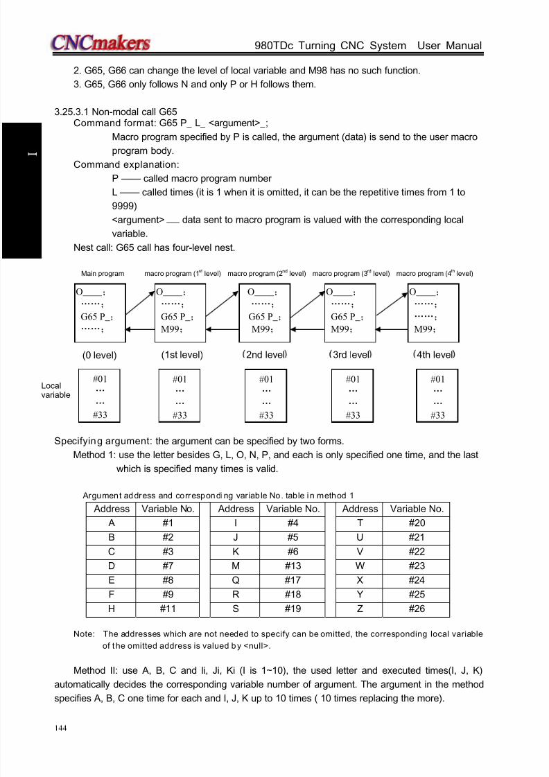
8/17/2019 980TDc CNC Turning Controller User Manual
http://slidepdf.com/reader/full/980tdc-cnc-turning-controller-user-manual 159/461
GSK980TDc Turning CNC System User Manual
144
P r o gr ammi n g
2. G65, G66 can change the level of local variable and M98 has no such function.
3. G65, G66 only follows N and only P or H follows them.
3.25.3.1 Non-modal call G65Command format: G65 P_ L_ <argument>_;
Macro program specified by P is called, the argument (data) is send to the user macroprogram body.
Command explanation:
P —— called macro program number
L —— called times (it is 1 when it is omitted, it can be the repetitive times from 1 to
9999)
<argument> —— data sent to macro program is valued with the corresponding local
variable.
Nest call: G65 call has four-level nest.
Main program macro program (1st level) macro program (2nd level) macro program (3rd level) macro program (4th level)
Specifying argument: the argument can be specified by two forms.
Method 1: use the letter besides G, L, O, N, P, and each is only specified one time, and the last
which is specified many times is valid.
Argument address and corresponding variab le No. table in method 1
Address Variable No. Address Variable No. Address Variable No.
A #1 I #4 T #20
B #2 J #5 U #21
C #3 K #6 V #22
D #7 M #13 W #23
E #8 Q #17 X #24
F #9 R #18 Y #25
H #11 S #19 Z #26
Note: The addresses which are not needed to specify can be omitted, the corresponding local variable
of the omitted address is valued by <null>.
Method II: use A, B, C and li, Ji, Ki (I is 1~10), the used letter and executed times(I, J, K)
automatically decides the corresponding variable number of argument. The argument in the method
specifies A, B, C one time for each and I, J, K up to 10 times ( 10 times replacing the more).
#01
…
… #33
#01
…
… #33
#01
…
… #33
#01
…
… #33
#01
…
… #33
Localvariable
O____ ;
……;
G65 P_ ;
……;
O____ ;
……;
G65 P_ ;
M99;
O____ ;
……;
……;
M99;
O____ ;
……;
G65 P_ ;
M99;
O____ ;
……;
G65 P_ ;
M99;
(0 level) (1st level) 2nd level 3rd level 4th level
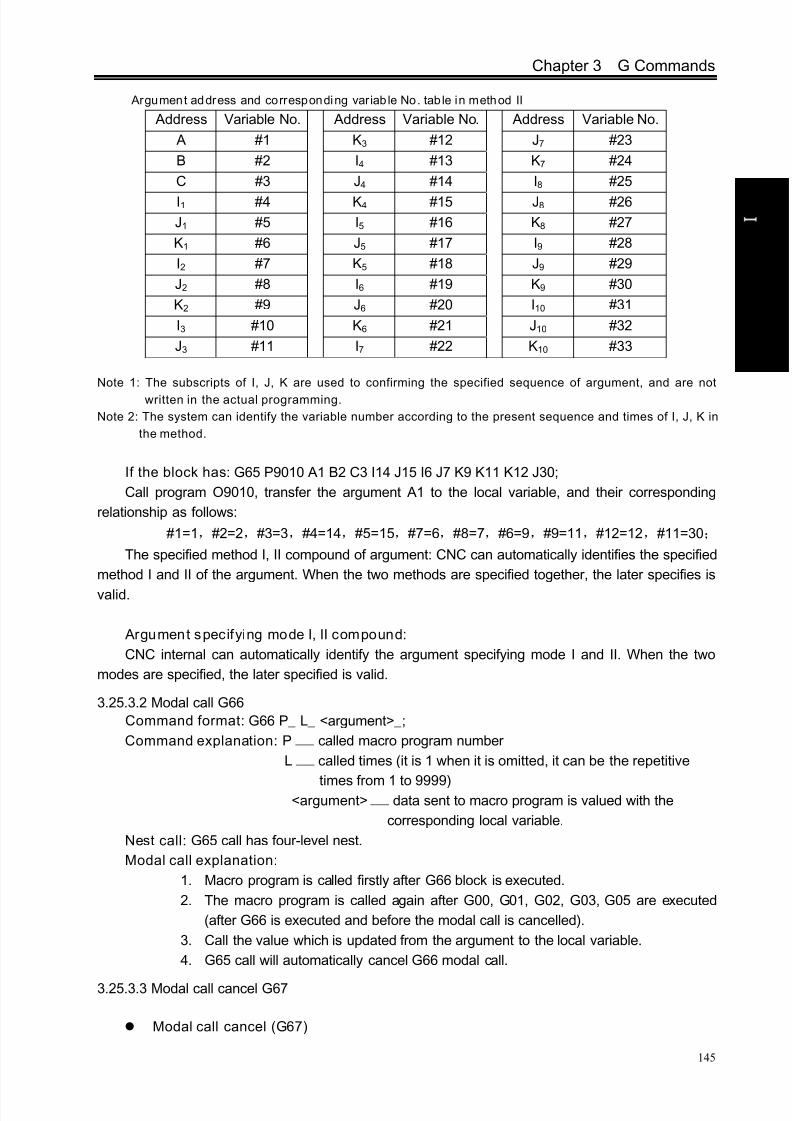
8/17/2019 980TDc CNC Turning Controller User Manual
http://slidepdf.com/reader/full/980tdc-cnc-turning-controller-user-manual 160/461
Chapter 3 G Commands
145
P r o gr ammi n g
Argument address and corresponding variab le No. tab le in method II
Address Variable No. Address Variable No. Address Variable No.
A #1 K3 #12 J7 #23
B #2 I4 #13 K7 #24
C #3 J4 #14 I8 #25
I1 #4 K4 #15 J8 #26
J1 #5 I5 #16 K8 #27
K1 #6 J5 #17 I9 #28
I2 #7 K5 #18 J9 #29
J2 #8 I6 #19 K9 #30
K2 #9 J6 #20 I10 #31
I3 #10 K6 #21 J10 #32
J3 #11 I7 #22 K10 #33
Note 1: The subscripts of I, J, K are used to confirming the specified sequence of argument, and are not
written in the actual programming.
Note 2: The system can identify the variable number according to the present sequence and times of I, J, K in
the method.
If the block has: G65 P9010 A1 B2 C3 I14 J15 I6 J7 K9 K11 K12 J30;
Call program O9010, transfer the argument A1 to the local variable, and their corresponding
relationship as follows:
#1=1,#2=2,#3=3,#4=14,#5=15,#7=6,#8=7,#6=9,#9=11,#12=12,#11=30;
The specified method I, II compound of argument: CNC can automatically identifies the specified
method I and II of the argument. When the two methods are specified together, the later specifies is
valid.
Argument specifying mode I, II compound:
CNC internal can automatically identify the argument specifying mode I and II. When the two
modes are specified, the later specified is valid.
3.25.3.2 Modal call G66
Command format: G66 P_ L_ <argument>_;
Command explanation: P —— called macro program number
L —— called times (it is 1 when it is omitted, it can be the repetitive
times from 1 to 9999)<argument> —— data sent to macro program is valued with the
corresponding local variable.
Nest call: G65 call has four-level nest.
Modal call explanation:
1. Macro program is called firstly after G66 block is executed.
2. The macro program is called again after G00, G01, G02, G03, G05 are executed
(after G66 is executed and before the modal call is cancelled).
3. Call the value which is updated from the argument to the local variable.
4. G65 call will automatically cancel G66 modal call.
3.25.3.3 Modal call cancel G67
Modal call cancel (G67)

8/17/2019 980TDc CNC Turning Controller User Manual
http://slidepdf.com/reader/full/980tdc-cnc-turning-controller-user-manual 161/461
GSK980TDc Turning CNC System User Manual
146
P r o gr ammi n g
Command format: G67;
Command explanation: cancel G66 modal macro program call
Application:
O2005(O2005) ;
G00 X100 Z50;
G66 P0100 L2 A2 B20 C20 I30 J20 K20; call P0100 two times when the system executes the block
G01 X80 Z50; call P0100 two times (update the local variable according to the argument) after the
system has executed the block
G67; cancel G66 modal call
G01 X20 Z50; the system does not call P0100 after it executes the block
M30;
3.26 Statement Macro Command
3.26.1 Arithmetic and logic operation
Table 3-20 Arithmetic and logic operation
Funct ion Expression format Remark
Definition or assignment #i = #j
addition
subtraction
multiplication
division
#i = #j + #k
#i = #j - #k
#i = #j * #k
#i = #j / #k
Or
AndExclusive Or
#i = #j OR #k
#i = #j AND #K#i = #j XOR #K
Logic operation is executed by
the binary system
Square root
Absolute value
Rounding-off
FUP
FIX
Natural logarithm
Exponential function
#i = SQRT[#j]
#i = ABS[#j]
#i = ROUND[#j]
#i = FUP [#j]
#i = FIX [#j]
#i = LN[#j]
#i = EXP[#j]
Sine
Arc sine
Cosine
Arc cosine
Tangent
Arc tangent
#i = SIN[#j]
#i = ASIN[#j]
#i = COS[#j]
#i = ACOS[#j]
#i = TAN[#j]
#i = ATAN[#i]/ [#j]
Angle unit is specified by
degree. For example: 90°30’
is expressed by 90.5°
BCD to BIN
BIN to BCD
#i = BIN[#j]
#i = BCD[#j]Used for switching with PMC
Relative explanation:
1. Angle unit
Angle units of SIN, COS, ASIN, ACOS, TAN and ATAN are degree (°). For example:
90°30 means to be 90.5ˊ ° (degree).
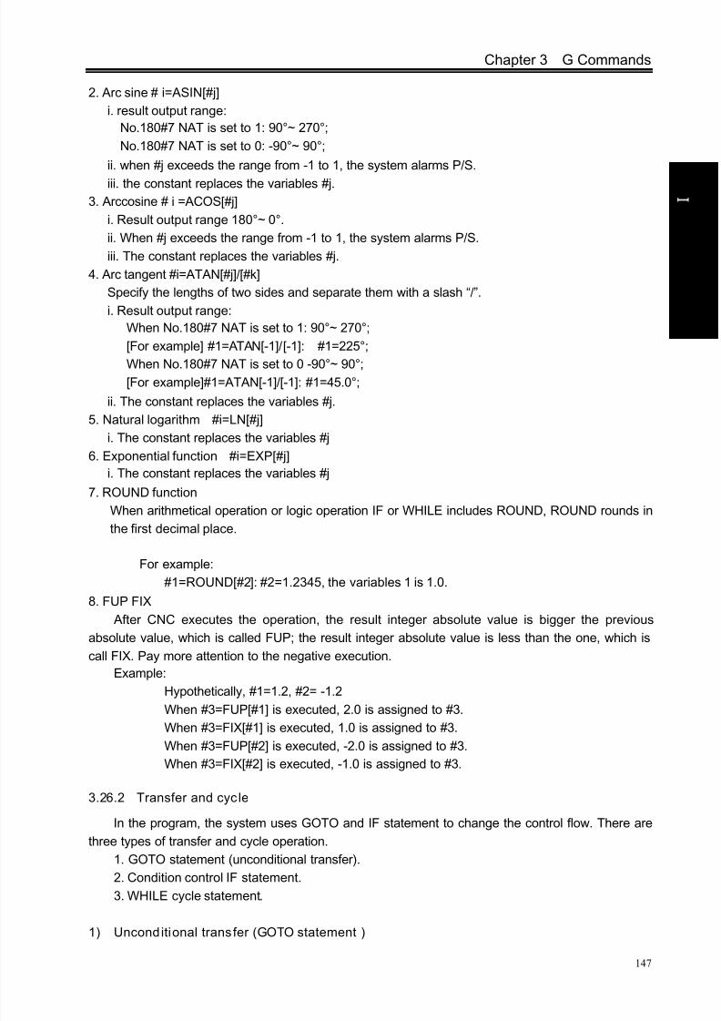
8/17/2019 980TDc CNC Turning Controller User Manual
http://slidepdf.com/reader/full/980tdc-cnc-turning-controller-user-manual 162/461
Chapter 3 G Commands
147
P r o gr ammi n g
2. Arc sine # i=ASIN[#j]
i. result output range:
No.180#7 NAT is set to 1: 90°~ 270°;
No.180#7 NAT is set to 0: -90°~ 90°;
ii. when #j exceeds the range from -1 to 1, the system alarms P/S.
iii. the constant replaces the variables #j.
3. Arccosine # i =ACOS[#j]
i. Result output range 180°~ 0°.
ii. When #j exceeds the range from -1 to 1, the system alarms P/S.
iii. The constant replaces the variables #j.
4. Arc tangent #i=ATAN[#j]/[#k]
Specify the lengths of two sides and separate them with a slash “/”.
i. Result output range:
When No.180#7 NAT is set to 1: 90°~ 270°;
[For example] #1=ATAN[-1]/[-1]: #1=225°;
When No.180#7 NAT is set to 0 -90°~ 90°;
[For example]#1=ATAN[-1]/[-1]: #1=45.0°;
ii. The constant replaces the variables #j.
5. Natural logarithm #i=LN[#j]
i. The constant replaces the variables #j
6. Exponential function #i=EXP[#j]
i. The constant replaces the variables #j
7. ROUND function
When arithmetical operation or logic operation IF or WHILE includes ROUND, ROUND rounds in
the first decimal place.
For example:
#1=ROUND[#2]: #2=1.2345, the variables 1 is 1.0.
8. FUP FIX
After CNC executes the operation, the result integer absolute value is bigger the previous
absolute value, which is called FUP; the result integer absolute value is less than the one, which is
call FIX. Pay more attention to the negative execution.
Example:
Hypothetically, #1=1.2, #2= -1.2
When #3=FUP[#1] is executed, 2.0 is assigned to #3.When #3=FIX[#1] is executed, 1.0 is assigned to #3.
When #3=FUP[#2] is executed, -2.0 is assigned to #3.
When #3=FIX[#2] is executed, -1.0 is assigned to #3.
3.26.2 Transfer and cycle
In the program, the system uses GOTO and IF statement to change the control flow. There are
three types of transfer and cycle operation.
1. GOTO statement (unconditional transfer).
2. Condition control IF statement.
3. WHILE cycle statement.
1) Unconditional transfer (GOTO statement )

8/17/2019 980TDc CNC Turning Controller User Manual
http://slidepdf.com/reader/full/980tdc-cnc-turning-controller-user-manual 163/461
GSK980TDc Turning CNC System User Manual
148
P r o gr ammi n g
Transfer to the block which serial number is n. The system alarms when others exceeds the
range from 1 to 99999, and it specifies the serial number with the statement.
Format: GOTO n; n: serial number(1~99999)
Example: GOTO 1;
GOTO #101;
2) Condit ional contro l (IF statement )
GOTO format: IF[ conditional statement]GOTO n;
When the specified conditional statement is valid, the system transfers to the block which serial
number is n; When the specified conditional statement is valid, the system executes the next block.
Example:
When the variable #1 is more than 10, the system transfers to the block which serial
number is N2.
N2 G00 X10.0;
THEN format: IF[conditional expression]THEN<macro program statement >;
When the condition expression is valid, the system executes only one statement following THEN.
Example: IF[#1 EQ #2] THEN #3=0;
When #1 value is equal to the #2, 0 is assigned to the variable #3; when they are not equal, the
system orderly executes the followings instead of the assignment statement after THEN.
Conditional expression: the conditional expression must include the conditional operator, two
sides of conditional operator can be variable, constant or expression, and it must be closed with the
brackets ‘[’ ‘]’.
Conditional operator: the system uses the conditional operators listed in the following table.
Conditional operator Meaning
EQ or = = Equal to (=)
NE or <> Not equal to (≠)
GT or > More than (>)GE or >= More than or equal to (≥)
LT or < Less than (<)
LE or <= Less than or equal to (≤)
Example: IF[3<>2]GOTO 2; its meaning: when 3 is not equal 2, the system skips to N2 block;
IF[#101>=7.22]THEN #101=SIN30; its meaning: when #101 is more than or equal to
7.22, the system executes the assignment after THEN. i.e. the sine value of 30 degree
is assigned to the variable #101.
Typical program: the following program counts the sum of the integer 1~10.
Program
IF [#1GT10] GOTO2;
If the conditionis not met.
If the conditionis met.

8/17/2019 980TDc CNC Turning Controller User Manual
http://slidepdf.com/reader/full/980tdc-cnc-turning-controller-user-manual 164/461
Chapter 3 G Commands
149
P r o gr ammi n g
3) Cycle (WHILE statement)
Specify one conditional expression after WHILE. When the specified conditional is valid, the
system executes the blocks between DO and END; otherwise, the system skips to the block after
END.
Example:
WHILE [conditional expression] DOm; (m=1, 2, 3)
When the condition When the
is not met. condition is met.
END m;
Explanation: when the specified condition is valid, the system executes the block between DO
and END; otherwise, executes the block after END. The two tabs after DO and END are consistent,
and the tab value can be 1, 2 or 3, otherwise, the system alarms.
Nest: the tab (1~3) in DO, END can be used many times. But the system alarms when there is
the intercross repetitive cycle in the program.
O9500#1=0;… …the sum is initialized to be 0
#2=1;… …the summand number is initialized to be 1
N1 IF[#2 GT 10]GOTO 2;… … the system skips to N2 when the summand is more than 10
#1= #1+#2; … …count the sum of two numbers
#2= #2+1; … … the summand adds 1GOTO 1; … … unconditionally skip to the block N1
N2 M30; … … end of program
Program

8/17/2019 980TDc CNC Turning Controller User Manual
http://slidepdf.com/reader/full/980tdc-cnc-turning-controller-user-manual 165/461
GSK980TDc Turning CNC System User Manual
150
P r o gr ammi n g
3.27 Metric/Inch Switch
Command format: G20; (inch input)
G21; (metric input)
Explanation: input/output unit of CNC system is divided into two, i.e., metric unit: mm and inch unit:inch.
Input unit of modifying the system has also:
Modifying BIT0 (metric/inch): 0: metric input 1: inch input
No. 001# completely corresponds to G20/G21, namely, the parameter also changes
when G20/G21 is executed; G20/G21 mode also changes when the parameter is
modified, and the alarm prompt occurs after modification. Parameters relevant to
metric/inch are referred to Installation & Connection, Section 3.2.17.
NotesNo.001#0(INI) input increment unit change
①. After the input increment unit is changed (inch/metric input), the following unit system is
changed: (i.e.: mm<>inch; mm/min<>inch/min):
-F specifies the feedrate (mm/min<>inch/min), thread lead (mm <>inch)
—position command (mm<>inch)
—tool compensation value (mm<>inch)
—MPG graduation unit (mm<>inch)
—movement distance in incremental feed (mm<>inch)
—some data parameters, including NO.49~NO.54, NO.56, NO.59, NO.60, NO.114~ NO.116,
NO.120~ NO.127, NO.140, No.141, No.154; the unit is 0.001mm(IS-B) in the metric input
system, is 0.0001inch(IS-B) in the inch input system. For example, the same parameter
NO.49 setting value is 100m, it means to be 0.1mm in the metric input system (G21), and
it means 0.01inch in the inch input system (G20).
②.The machine coordinates will automatically switch after the input increment unit change is
switched:
No.004#0(SCW) output command unit change
SCW=0: the system minimal command increment uses the metric output (0.001mm)
SCW=1: the system minimal command increment uses the inch output (0.0001inch)
Some data parameter meanings will be changed when the output control bit parameter SCW ischanged:
①.Speed parameter:
Metric machine: mm/min
Inch machine: 0.1 inch/min
Example: when the speed is set to 3800, the metric machine is 3800 mm/min and the
inch machine is 380 inch/min.
Speed parameters: No.22, No.23, No.27, No.28~No.31, No.32, No.33, No.41, No.107,
No.113;
②.Position(length) parameter
metric machine: 0.001 mminch machine: 0.0001 inch
When the setting is 100, the metric machine is 0.1mm and the inch machine is 0.01
8/17/2019 980TDc CNC Turning Controller User Manual
http://slidepdf.com/reader/full/980tdc-cnc-turning-controller-user-manual 166/461
Chapter 3 G Commands
151
P r o gr ammi n g
inch.
Position parameters: No.34, No.35, No.37~No.40, No.45~No.48, No.102~No.104 and
all pitch error compensation parameter;
Note 1: When the minimal inpu t increment unit and the minimal command unit are different, the maximal error
is the half of minimal command un it. The error cannot be accumulated.Note 2: The current system increment is IS-B in the above explanation.

8/17/2019 980TDc CNC Turning Controller User Manual
http://slidepdf.com/reader/full/980tdc-cnc-turning-controller-user-manual 167/461
GSK980TDc Turning CNC System User Manual
152
P r o gr ammi n g
CHAPTER 4 TOOL NOSE RADIUS COMPENSATION (G41, G42)
4.1 Application
4.1.1 Overview
Part program is compiled generally for one point of tool according to a workpiece contour. The
point is generally regarded as the tool nose A point in an imaginary state (there is no imaginary tool
nose point in fact and the tool nose radius can be omitted when using the imaginary tool nose point to
program) or as the center point of tool nose arc ( as Fig. 4-1). Its nose of turning tool is not the
imaginary point but one arc owing to the processing and other requirement in the practical machining.
There is an error between the actual cutting point and the desired cutting point, which will cause the
over- or under-cutting affecting the part precision. So a tool nose radius compensation is needed in
machining to improve the part precision.
Fig. 4-1 Tool
Fig. 4-2 Tool nose center path
4.1.2 Imaginary tool nose direction
Suppose that it is generally difficult to set the tool nose radius center on the initial position as Fig.
4-3; suppose that it is easily set the tool nose on it as Fig. 4-4; The tool nose radius can be omitted in
programming. Fig. 4-5 and Fig.4-6 correspond separately to the tool paths of tool nose center
programming and imaginary tool nose programming when tool nose radius is executed or not.
Tool path with imaginary tool nose and without C compensation
Tool path with imaginarytool nose and Ccompensation
Tool nose center path without C compensation
Tool nose center path with C compensation
Error
Tool nose
Workpiece

8/17/2019 980TDc CNC Turning Controller User Manual
http://slidepdf.com/reader/full/980tdc-cnc-turning-controller-user-manual 168/461
Contents
153
P r o gr ammi n g
Tool path is shown in Fig.4-5 when the tool nose center programming is executed.
Fig. 4-5-1 the tool nose center path is Fig. 4-5-2 precise cutting with toolthe same that of programmed path without radius compensationtool radius compensation
The tool path is shown in Fig. 4-6 when imaginary tool nose programming is executed
Fig. 4-6-1 the imaginary tool nose path is Fig. 4-5-2 precise cutting with toolthe same that of programmed path without radius compensationtool radius compensation
The tool is supposed to one point in programming but the actual cutting blade is not one ideal
point owing to machining technology. Because the cutting blade is not one point but one circular,
machining error is caused which can be deleted by tool nose circular radius compensation. In actual
machining, suppose that there are different position relationship between tool nose point and tool
nose circular center point, and so it must create correct its direction of imaginary tool nose.
From tool nose center to imaginary tool nose, set imaginary tool nose numbers according to tool
direction in cutting. Suppose there are 10 kinds of tool nose setting and 9 directions for position
relationship. The tool nose directions are different in different coordinate system (rear tool post
coordinate system and front tool post coordinate system) even if they are the same tool nose
direction numbers as the following figures. In figures, it represents relationships between tool noseand starting point, and end point of arrowhead is the imaginary tool nose; T1~T8 in rear tool post
coordinate system is as Fig. 4-7; T1~T8 in front tool post coordinate system is as Fig. 4-8. The tool
Starting pointStarting point
Fig. 4-3 Programming with tool nose Fig. 4-4 Programming with imaginary tool nose
Programmed pathProgrammed path
Tool nosecenter ath
Tool nosecenter ath Start compensation
Programmed path
Imaginary tool nosepath
Programmed path
Imaginary tool nosepath
Start compensation

8/17/2019 980TDc CNC Turning Controller User Manual
http://slidepdf.com/reader/full/980tdc-cnc-turning-controller-user-manual 169/461
GSK980TDc Turning CNC System User Manual
154
P r o gr ammi n g
nose center and starting point for T0 and T9 are shown in Fig. 4-9.
Z axis
X axis
Imaginary tool
nose No.1
Imaginary tool
nose No. 2
Imaginary tool
nose No.3 Imaginary tool
nose No.4
Imaginary tool
nose No.5 Imaginary tool
nose No.6
Imaginary tool
nose No.7 Imaginary tool
nose No. 8
Fig. 4-7 Imaginary tool nose number in rear tool post coordinate system
Rear tool post coordinate system
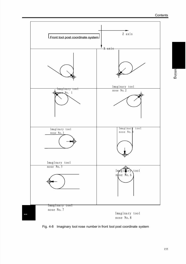
8/17/2019 980TDc CNC Turning Controller User Manual
http://slidepdf.com/reader/full/980tdc-cnc-turning-controller-user-manual 170/461
Contents
155
P r o gr ammi n g
Z axis
X axis
Imaginary tool
nose No. 1
Imaginary tool
nose No.2
Imaginary tool
nose No.3
Imaginary tool
nose No.4
Imaginary tool
nose No.5
Imaginary tool
nose No.6
Imaginary tool
nose No.7 Imaginary tool
nose No.8
Fig. 4-8 Imaginary tool nose number in front tool post coordinate system
Front tool post coordinate system

8/17/2019 980TDc CNC Turning Controller User Manual
http://slidepdf.com/reader/full/980tdc-cnc-turning-controller-user-manual 171/461
GSK980TDc Turning CNC System User Manual
156
P r o gr ammi n g
Fig. 4-9 Tool nose center on starting point
4.1.3 Compensation value setting
Preset imaginary tool nose number and tool nose radius value for each tool before executing
tool nose radius compensation. Set the tool nose radius compensation value in OFFSET window (as
Fig. 4-1), R is tool nose radius compensation value and T is imaginary tool nose number.
Table 4-1 CNC tool nose radius compensation value display window
number X Z R T000 0.000 0.000 0.000 0
001 0.020 0.030 0.020 2
002 1.020 20.123 0.180 3
… … … … …
032 0.050 0.038 0.300 6
Note: X tool offset value can be specified in diameter or radius, set by No.004 Bit4 ORC, offset value is in
radius when ORC=1 and is in d iameter when ORC=0.
In toolsetting, the tool nose is also imaginary tool nose point of Tn (n=0~9) when takingTn(n=0~9) as imaginary tool nose. For the same tool, offset value from standard point to tool nose
radius center (imaginary tool nose is T3) is different with that of ones from standard point to imaginary
tool nose(imaginary tool nose is T3) when T0 and T3 tool nose points are selected to toolsetting in
rear tool post coordinate system, taking tool post center as standard point. It is easier to measure
distances from the standard point to the tool nose radius center than from the standard point to the
imaginary tool nose, and so set the tool offset value by measuring distance from the standard point to
the imaginary tool nose(tool nose direction of T3).

8/17/2019 980TDc CNC Turning Controller User Manual
http://slidepdf.com/reader/full/980tdc-cnc-turning-controller-user-manual 172/461
Contents
157
P r o gr ammi n g
Fig. 4-10 Tool offset value of tool post center as benchmark
4.1.4 Command format
X Z T ;
Commands Function specifications Remark
G40 Cancel the tool nose radius compensation
See Fig.4-11
and 4-12G41
Tool nose radius left compensation is specified by G41 in rear tool
post coordinate system and tool nose radius right compensation is
specified by G41 in front tool post coordinate system
G42 Tool nose radius right compensation is specified by G42 in rear tool
post coordinate system and tool nose radius left compensation is
specified by G42 in front tool post coordinate system
4.1.5 Compensation direction
Specify its direction according to relative position between tool nose and workpiece when
executing tool nose radius compensation is shown in Fig. 4-11 and Fig.4-12.
G40
G41
G42
G00
G01

8/17/2019 980TDc CNC Turning Controller User Manual
http://slidepdf.com/reader/full/980tdc-cnc-turning-controller-user-manual 173/461
GSK980TDc Turning CNC System User Manual
158
P r o gr ammi n g
Z
X
G42:Tool is right to
workpiece from its
movement direction
G41:Tool is left to
workpiece from its
movement direction
Workpiece
Tool
Fig. 4-11 Compensation direction of rear coordinate system
Z axis Z axis
X axis X axis

8/17/2019 980TDc CNC Turning Controller User Manual
http://slidepdf.com/reader/full/980tdc-cnc-turning-controller-user-manual 174/461
Contents
159
P r o gr ammi n g
Z
G41:Tool is right to
workpiece from its
movement direction
G42:Tool is left to
workpiece from its
movement direction
Workpiece
Tool
X
Fig. 4-12 Compensation direction of front coordinate system
4.1.6 Notes
The system is in tool nose radius compensation mode at initial state, and starts to create tool
nose radius compensation offset mode when executing G41 or G42. When the system starts to
execute compensation, it pre-read two blocks, and the next block is saved to storage for tool
nose radius compensation when executing one of them. The system reads two blocks in
“Single” mode and stops after executing end point of the first block.
In tool nose radius compensation mode, the tool nose center moves to end point of previous
block and is vertical to its path when the system executes two block or more than blocks without
motion Command.
The system cannot create and cancel tool nose radius compensation.
Tool nose radius R is without negative value, otherwise there is a mistake running path.
Tool nose radius compensation is created and cancelled in G00 or G01 instead of G02 or G03,
otherwise, the system alarms.
The system cancels the tool nose radius compensation mode when pressingRESET
key.
G40 must be specified to cancel offset mode before the program is ended, otherwise the tool
path offsets one tool nose radius.
The system executes the tool nose radius compensation in main program and subprogram but
X axis
Z axisZ axis
X axis

8/17/2019 980TDc CNC Turning Controller User Manual
http://slidepdf.com/reader/full/980tdc-cnc-turning-controller-user-manual 175/461
GSK980TDc Turning CNC System User Manual
160
P r o gr ammi n g
must cancel it before calling subprogram and then create it again in the subprogram.
The system does not execute the tool nose radius compensation in G71, G72, G73, G74, G75,
G76 and cancel it temporarily.
The system executes the tool nose radius compensation in G90, G94, it offsets one tool nose
radius for G41 or G42.
4.1.7 Application
Machine a workpiece in the front tool post coordinate system as Fig. 4-13. Tool number:
T0101, tool nose radius R=2, imaginary tool nose number T=3.
X
Z
R 6
Fig. 4-13
For toolsetting in Offset Cancel mode, after toolsetting, Z axis offsets one tool nose radius
and its direction is relative to that of imaginary tool nose and toolsetting point, otherwise the
system excessively cuts tool nose radius when it starts to cut.
Set the tool nose radius R and imaginary tool nose direction in “TOOL OFFSET&WEAR”
window as following:
Table 4-3
No. X Z R T
001 2.000 3
002 … … … …
… … … … …
007 … … … …
008 … … … …
Program:
G00 X100 Z50 M3 T0101 S600; (Position, start spindle, tool change and execute
tool compensation)
G42 G00 X0 Z3; (Set tool nose radius compensation)G01 Z0 F300; (Start cutting)
X16;

8/17/2019 980TDc CNC Turning Controller User Manual
http://slidepdf.com/reader/full/980tdc-cnc-turning-controller-user-manual 176/461
Contents
161
P r o gr ammi n g
Z-14 F200;
G02 X28 W-6 R6;
G01 W-7;
X32;
Z-35;
G40 G00 X90 Z40; (Cancel tool nose radius compensation)
G00 X100 Z50 T0100;
M30;
4.2 Tool Nose Radius Compensation Offset Path
4.2.1 Inner and outer side
Inside is defined that an angle at intersection of two motion blocks is more than or equal to 180°;
Outside is 0~180°.
3 steps to execute tool nose radius compensation: tool compensation creation, tool
compensation execution and tool compensation canceling.
Tool traverse is called tool compensation creation (starting tool) from offset canceling to G41 orG42 execution.
Note: Meanings of S, L, C in the following figures are as follows: S――Stop point of single block; L――linear;
C――circular.
Note: Tool movement path is marked with the tool nose direction 0 in the following figures.
Note: Tool path i s described in rear tool post coordinate system and too l compensation direction G41 in the
following figures.
Workpiece side
Inner
Outer
Programmed path
Programmed path
Workpiece side
Outer

8/17/2019 980TDc CNC Turning Controller User Manual
http://slidepdf.com/reader/full/980tdc-cnc-turning-controller-user-manual 177/461
GSK980TDc Turning CNC System User Manual
162
P r o gr ammi n g
4.2.2 Tool traversing when starting tool
(a) Tool t raversing inside along corner(α≥180°)
1) Linear → linear 2) linear→ circular
Workpiece
Programmed path
α
LS L
Tool nose center path
r
α
L
SC
Workpiece
Programmed pathTool nose center path
(b) Tool traversing inside along corner(180°>α≥90°)
1) Linear → linear 2) linear → circular
r r
L S LL
αWorkpiece
Programmed path
Tool nose center path
(c) Tool traversing inside along corner (α<90°)
1)Linear →linear 2)Linear →circular
r
r
L
L
L
L
L
αProgrammed path
Tool nose center path
r
r
L
L
LC
S
α
Workpiece
Programmed pathTool nose center path
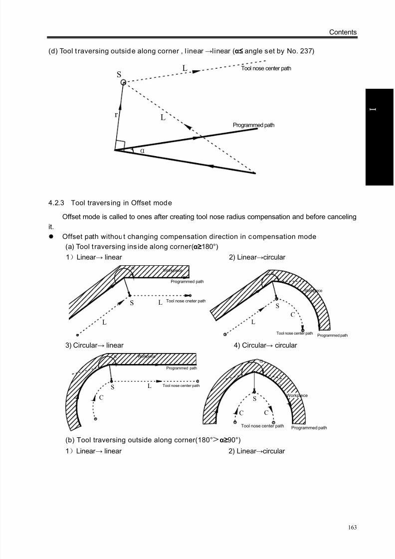
8/17/2019 980TDc CNC Turning Controller User Manual
http://slidepdf.com/reader/full/980tdc-cnc-turning-controller-user-manual 178/461
Contents
163
P r o gr ammi n g
4.2.3 Tool traversing in Offset mode
Offset mode is called to ones after creating tool nose radius compensation and before canceling
it.
Offset path without changing compensation direction in compensation mode
(a) Tool t raversing ins ide along corner(α≥180°)
1)Linear → linear 2) Linear →circular
LS
L
α
Tool nose cneter path
Programmed path
Workpiece
C
S
L
α
Tool nose center pathProgrammed path
Workpiece
3) Circular → linear 4) Circular → circular
L
C
S
α Workpiece
Programmed path
Tool nose center path
S
CC
α
Workpiece
Programmed pathTool nose center path
(b) Tool traversing outside along corner(180°>α≥90°)
1)Linear → linear 2) Linear →circular
(d) Tool t raversing outside along corner , l inear →l inear (α≤ angle set by No. 237)
α
L
L
r
S
Programmed path
Tool nose center path
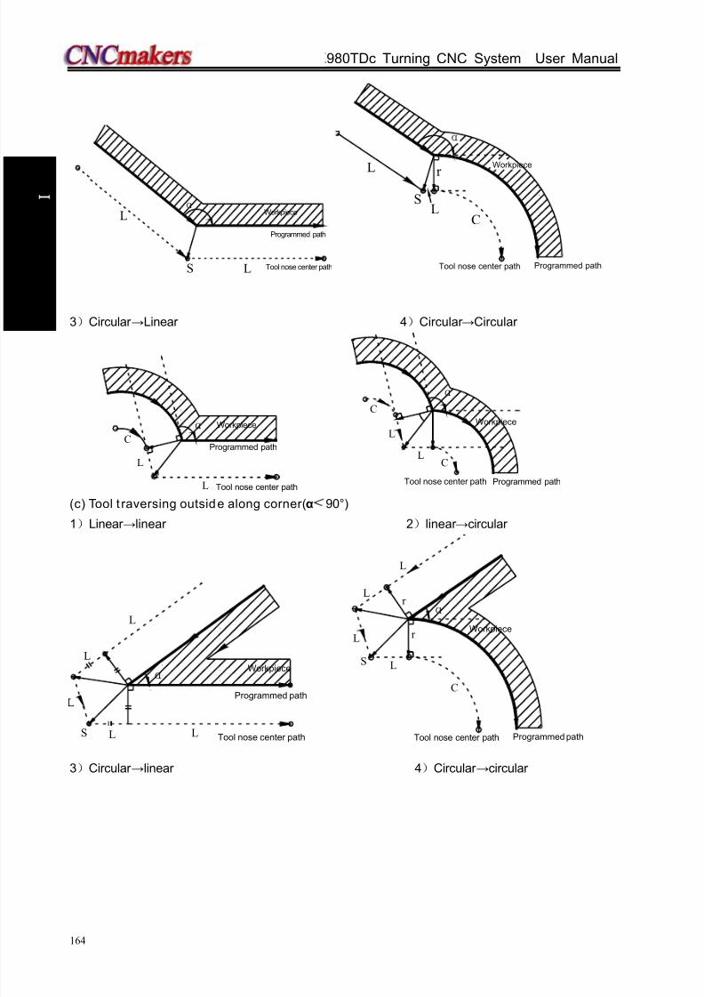
8/17/2019 980TDc CNC Turning Controller User Manual
http://slidepdf.com/reader/full/980tdc-cnc-turning-controller-user-manual 179/461
GSK980TDc Turning CNC System User Manual
164
P r o gr ammi n g
S
αL
L
Workpiece
Programmed path
Tool nose center path
L
S
CL
α
r
Workpiece
Tool nose center path Programmed path
3)Circular →Linear 4)Circular →Circular
α
L
C
L
Workpiece
Programmed path
Tool nose center path
α
CL
C
L
Workpiece
Programmed pathTool nose center path
(c) Tool t raversing outside along corner(α<90°)
1)Linear →linear 2)linear →circular
L
LL
L
α
S
Workpiece
Programmed path
Tool nose center path
L
L
r
α
L
C
S
L
r
Tool nose center path Programmed path
Workpiece
3)Circular →linear 4)Circular →circular
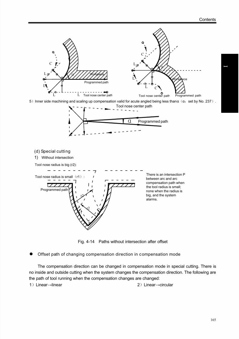
8/17/2019 980TDc CNC Turning Controller User Manual
http://slidepdf.com/reader/full/980tdc-cnc-turning-controller-user-manual 180/461
Contents
165
P r o gr ammi n g
L
C
L
L L
α Workpiece
Programmed path
Tool nose center path
L
C
L
L C
α
Workpiece
Programmed pathTool nose center path 5)Inner side machining and scaling up compensation valid for acute angled being less than α(α:set by No. 237).
α
Tool nose center path
Programmed path
(d) Special cutting
1) Without intersection
Programmed path
P
Tool nose radius is small(r1):
r1 r1
r2
r2
Tool nose radius is big (r2):
There is an intersection P
between arc and arccompensation path whenthe tool radius is small;none when the radius isbig, and the systemalarms.
Fig. 4-14 Paths without intersection after offset
Offset path of changing compensation direction in compensation mode
The compensation direction can be changed in compensation mode in special cutting. There is
no inside and outside cutting when the system changes the compensation direction. The following are
the path of tool running when the compensation changes are changed:
1)Linear →linear 2)Linear →circular

8/17/2019 980TDc CNC Turning Controller User Manual
http://slidepdf.com/reader/full/980tdc-cnc-turning-controller-user-manual 181/461
GSK980TDc Turning CNC System User Manual
166
P r o gr ammi n g
r
r
G42G41
S
L
LProgrammed path
Tool center path
Workpiece
Workpiece
G42
G41
S
C
L
r
r Workpiece
Workpiece
Programmed path
Tool center path
3)Circular →linear 4)Circular →circular
S
r
r
LC
G42
Workpiece
Workpiece
Tool center path
Programmed path
G41
r r
C
C
Workpice
Workpiece
G41
G42
STool center path
Programmed path
5) No intersection when compensation is executed normally
When the system executes G41 and G42 to change the offset direction between block A and B, a
vector perpendicular to block B is created from its starting point.
i ) L inear----Linear
Fig. 4-15a Linear—linear, no intersection(changing compensation direction)
ii ) Linear ---circular

8/17/2019 980TDc CNC Turning Controller User Manual
http://slidepdf.com/reader/full/980tdc-cnc-turning-controller-user-manual 182/461
Contents
167
P r o gr ammi n g
G41G42
G42
L L
C
Tool nose center path
Programmed path
Fig. 4-15b Linear—circular without intersection (changing compensation direction)
iii ) Circular-----circular
LL
C
C
G42
G41
Tool nose center path
Programmed path
Fig. 4-15c Circular—circular without intersection (changing compensation direction)
4.2.4 Tool traversing in Offset canceling mode
In compensation mode, when the system executes a block with one of the followings, it enters
compensation canceling mode, which is defined to compensation canceling of block.
1. Execute G40 in a program;
2. Execute M30.
The system cannot execute G02 and G03 when canceling C tool compensation (tool nose radius
compensation), otherwise the system alarms and stops run.
In compensation canceling mode, the system executes the block and ones in the register for tool
nose radius compensation. At the moment, the run stops after one block is executed when singleblock is ON. The system executes the next one but does not read its following one when pressing
CYCLE START button again.
(a) Tool traversing ins ide along corner(α≥180°)
1)Linear →linear 2)Circular →linear

8/17/2019 980TDc CNC Turning Controller User Manual
http://slidepdf.com/reader/full/980tdc-cnc-turning-controller-user-manual 183/461
GSK980TDc Turning CNC System User Manual
168
P r o gr ammi n g
α
r G40
S
L
LTool center path
Programmed path
Workpiece
L
S
G40r
α
CProgrammed path
Tool center path
Workpiece
(b) Tool traversing outside along corner(180°>α≥90°)
1)Linear →linear 2)Circular →linear
L
r
α
r
G40
S
LL
Workpiece
Intersection
Programmed path
Tool center path C
α
r
S
L
ce
L
IntersectionL
r
(c) Tool t raversing outside along corner(α<90°)
1)Linear →linear 2)Circular →linear
L
L
L
S
G40
r
α
r
L
Programmed path
Workpiece
Tool center path
L
r
C
α
r
G40
S
L
L
L
Tool center path
Workpiece
Programmed path
4.2.5 Tool interference check
“Interference” is defined that the tool cuts workpiece excessively and it can find out excessive
cutting in advance, the interference check is executed even if the excessive cutting is not created, but
the system cannot find out all tool interferences.
(1) Fundamental conditions
1) The tool path direction is different that of program path (angle is 90°~270° ).
2) There is a big difference (α>180°) for two angles between starting point and end point of tool
nose center path, and between starting point and end point of program path.
Example: linear machining

8/17/2019 980TDc CNC Turning Controller User Manual
http://slidepdf.com/reader/full/980tdc-cnc-turning-controller-user-manual 184/461
Contents
169
P r o gr ammi n g
Fig. 4-16a Machining interference (1)
Fig. 4-16b Machining interference (2)
(2) Executing it w ithout actual interference
1) Concave groove less than compensation value
Fig. 4-17 Executing interference (1)
Directions of block B and tool nose radius compensation path are opposite without interference,
the tools stops and the system alarms.
2) Concave channel less than compensation value
Direction difference of two paths(180°)
Tool nose center path
Programmed path

8/17/2019 980TDc CNC Turning Controller User Manual
http://slidepdf.com/reader/full/980tdc-cnc-turning-controller-user-manual 185/461
GSK980TDc Turning CNC System User Manual
170
P r o gr ammi n g
Fig. 4-18 Executing interference (2)
Directions of block B and tool nose radius compensation path are opposite without interference,
the tools stops and the system alarms.
4.2.6 Commands for canceling compensation vector temporarily
In compensation mode, the compensation vector is cancelled temporarily in G50, G71~G76 and
is automatically resumed after executing the commands. At the moment, the compensation is
cancelled temporarily and the tool directly moves from intersection to a point for canceling
compensation vector. The tool directly moves again to the intersection after the compensation mode
is resumed.
Setting coordinate system in G50
Fig. 4-19 Temporary compensation vector in G50
Note: SS indicates a point at which the tool stops twice in Single mode.
Reference poin t automatic return G28
In compensation mode, the compensation is cancelled in a middle point and is automatically
resumed after executing the reference point return in G28.
Fig. 4-20 Cancel compensation vector temporarily in G28 G71~G75 compound cycle; G76, G92 thread cutting
When executing G71~G76 , G96 thread cutting, the system does not execute the tool nose

8/17/2019 980TDc CNC Turning Controller User Manual
http://slidepdf.com/reader/full/980tdc-cnc-turning-controller-user-manual 186/461
Contents
171
P r o gr ammi n g
radius compensation and cancel it temporarily, and there is G00, G01,in the following blocks, and
the system automatically recovers the compensation mode.
G32, G33,G34 thread cutting
They cannot run in the tool nose radius compensation mode, otherwise, No.131 alarm occurs
“……CANNOT USED TO C COMPENSATION”.
Fig. 4-21 Cancel compensation vector temporarily in G71~G76
G32, G33, G34 constant thread cuttingThey cannot be executed in tool nose radius compensation mode, otherwise, No. 131 alarm
occurs “……the command cannot be used in C compensation mode.”
G90, G94 (taking an example of G42)
Compensation method of tool nose radius compensation in G90 or G94:
A. Cancel the previous tool nose radius compensation;
B. Create the previous C compensation before cutting, and the path in the following figure①
creates the previous radius compensation mode;
C. The paths 2, 3 in the following figure are the radius compensation cutting;
D. The path 4 in the following figure can cancel the radius compensation, and the tool returns to
the cycle starting point; there is G00,G01 in the following block, and the CNC automatically
recovers the compensation mode.
1
2
3
4
Programmed path
Tool nose center path
4
3
2
1
Programmed path
Tool nose center path
Fig. 4-22 Offset direction of G90 tool nose Fig. 4-23 Offset direction of G94 tool nose
radius compensation radius compensation

8/17/2019 980TDc CNC Turning Controller User Manual
http://slidepdf.com/reader/full/980tdc-cnc-turning-controller-user-manual 187/461
O p er a t i on
Operation

8/17/2019 980TDc CNC Turning Controller User Manual
http://slidepdf.com/reader/full/980tdc-cnc-turning-controller-user-manual 188/461
Chapter 1 Operation Mode and Display Interface
173
O p er a t i on
CHAPTER 1 OPERATION MODE AND DISPLAY INTERFACE
1.1 Panel Divis ion
GSK980TDc, GSK980TDc-V CNC system uses an integrated panel, which is divided as follows:
GSK980TDc panel division
GSK980TDc-V panel division
Machine panel
Display menuEdit keyboard
Soft function key
LCD
State indicator
State indicator
Machine panel
Display menu
Edit keyboard
Soft function key
LCD
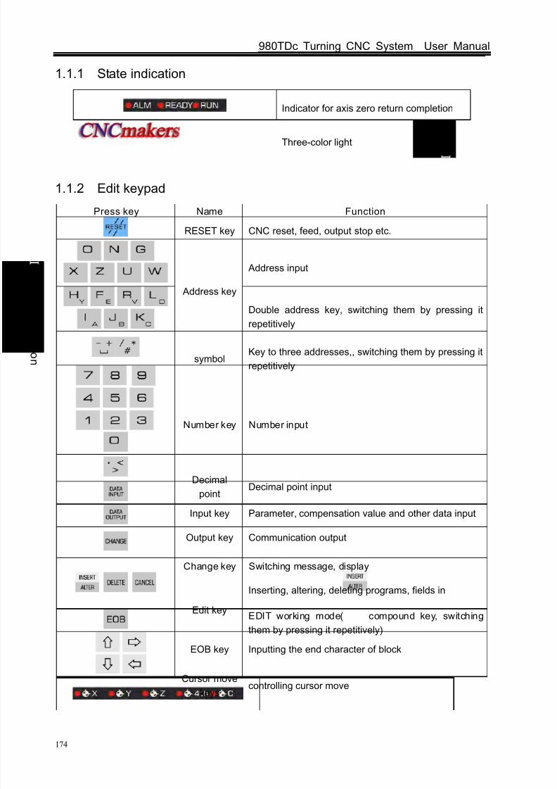
8/17/2019 980TDc CNC Turning Controller User Manual
http://slidepdf.com/reader/full/980tdc-cnc-turning-controller-user-manual 189/461
GSK980TDc Turning CNC System User Manual
174
O p er a t i on
1.1.1 State indication
Indicator for axis zero return completion
Three-color light
1.1.2 Edit keypad
Press key Name Function
RESET key CNC reset, feed, output stop etc.
Address input
Address key
Double address key, switching them by pressing it
repetitively
symbolKey to three addresses,, switching them by pressing it
repetitively
Number key Number input
Decimal
pointDecimal point input
Input key Parameter, compensation value and other data input
Output key Communication output
Change key Switching message, display
Edit key
Inserting, altering, deleting programs, fields in
EDIT working mode( compound key, switching
them by pressing it repetitively)
EOB key Inputting the end character of block
Cursor move
keyscontrolling cursor move
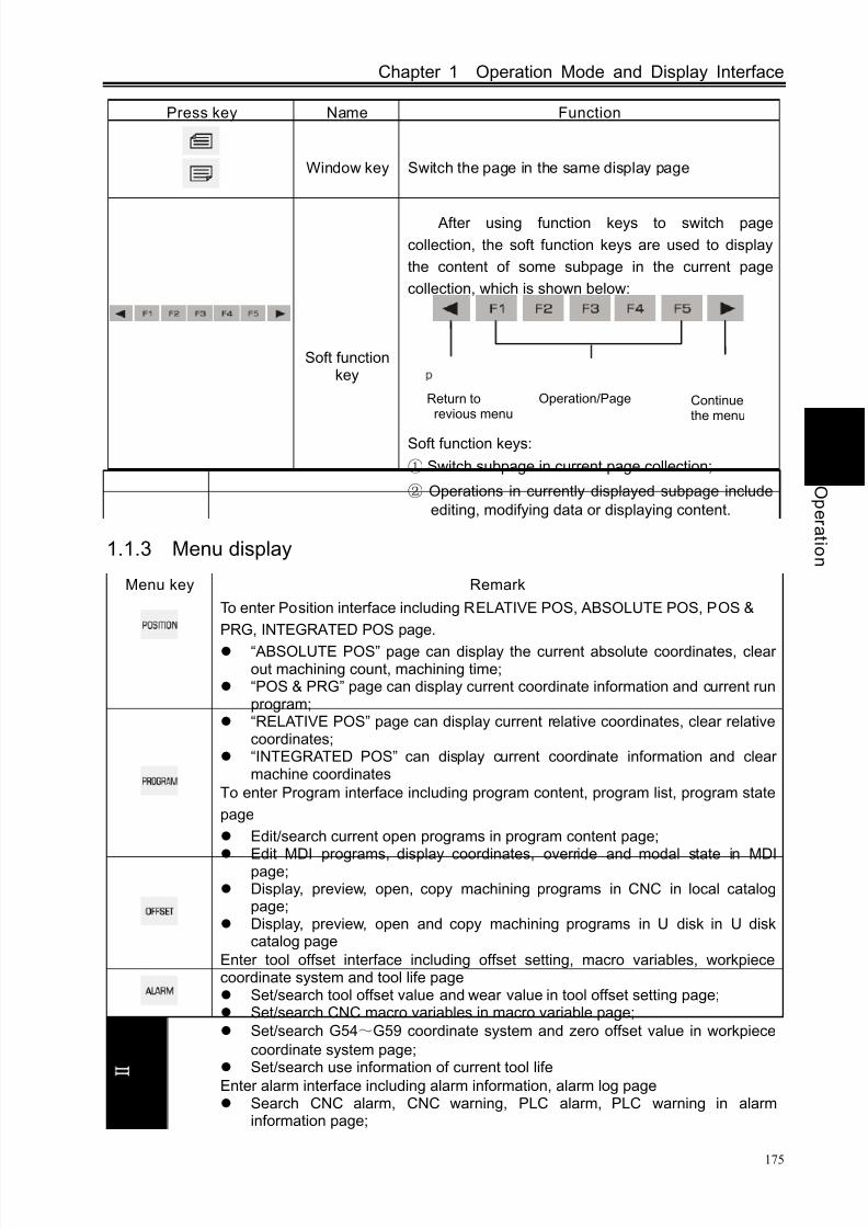
8/17/2019 980TDc CNC Turning Controller User Manual
http://slidepdf.com/reader/full/980tdc-cnc-turning-controller-user-manual 190/461
Chapter 1 Operation Mode and Display Interface
175
O p er a t i on
Press key Name Function
Window key Switch the page in the same display page
Soft functionkey
After using function keys to switch page
collection, the soft function keys are used to display
the content of some subpage in the current page
collection, which is shown below:
Soft function keys:
① Switch subpage in current page collection;
② Operations in currently displayed subpage include
editing, modifying data or displaying content.
1.1.3 Menu display
Menu key Remark
To enter Position interface including RELATIVE POS, ABSOLUTE POS, POS &
PRG, INTEGRATED POS page.
“ABSOLUTE POS” page can display the current absolute coordinates, clearout machining count, machining time;
“POS & PRG” page can display current coordinate information and current runprogram;
“RELATIVE POS” page can display current relative coordinates, clear relativecoordinates;
“INTEGRATED POS” can display current coordinate information and clearmachine coordinates
To enter Program interface including program content, program list, program state
page
Edit/search current open programs in program content page;
Edit MDI programs, display coordinates, override and modal state in MDIpage; Display, preview, open, copy machining programs in CNC in local catalog
page; Display, preview, open and copy machining programs in U disk in U disk
catalog page
Enter tool offset interface including offset setting, macro variables, workpiececoordinate system and tool life page Set/search tool offset value and wear value in tool offset setting page; Set/search CNC macro variables in macro variable page;
Set/search G54~G59 coordinate system and zero offset value in workpiece
coordinate system page; Set/search use information of current tool life
Enter alarm interface including alarm information, alarm log page Search CNC alarm, CNC warning, PLC alarm, PLC warning in alarm
information page;
Operation/PageReturn torevious menu
Continuethe menu
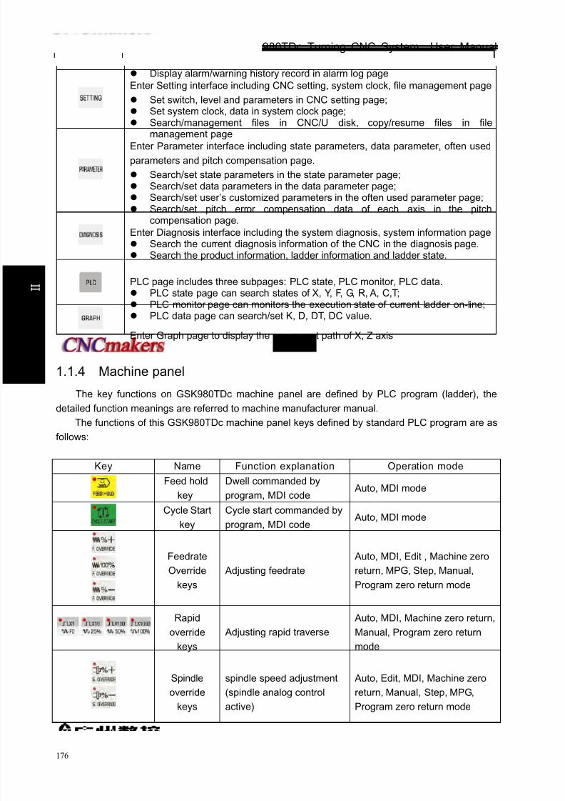
8/17/2019 980TDc CNC Turning Controller User Manual
http://slidepdf.com/reader/full/980tdc-cnc-turning-controller-user-manual 191/461
GSK980TDc Turning CNC System User Manual
176
O p er a t i on
Display alarm/warning history record in alarm log page
Enter Setting interface including CNC setting, system clock, file management page
Set switch, level and parameters in CNC setting page; Set system clock, data in system clock page; Search/management files in CNC/U disk, copy/resume files in file
management page
Enter Parameter interface including state parameters, data parameter, often used
parameters and pitch compensation page.
Search/set state parameters in the state parameter page; Search/set data parameters in the data parameter page; Search/set user’s customized parameters in the often used parameter page; Search/set pitch error compensation data of each axis in the pitch
compensation page.
Enter Diagnosis interface including the system diagnosis, system information page Search the current diagnosis information of the CNC in the diagnosis page. Search the product information, ladder information and ladder state.
PLC page includes three subpages: PLC state, PLC monitor, PLC data. PLC state page can search states of X, Y, F, G, R, A, C,T; PLC monitor page can monitors the execution state of current ladder on-line; PLC data page can search/set K, D, DT, DC value.
Enter Graph page to display the movement path of X, Z axis
1.1.4 Machine panel
The key functions on GSK980TDc machine panel are defined by PLC program (ladder), the
detailed function meanings are referred to machine manufacturer manual.
The functions of this GSK980TDc machine panel keys defined by standard PLC program are as
follows:
Key Name Function explanation Operation mode
Feed hold
key
Dwell commanded by
program, MDI code Auto, MDI mode
Cycle Start
key
Cycle start commanded by
program, MDI code Auto, MDI mode
FeedrateOverride
keys
Adjusting feedrate Auto, MDI, Edit , Machine zeroreturn, MPG, Step, Manual,
Program zero return mode
Rapid
override
keys
Adjusting rapid traverse
Auto, MDI, Machine zero return,
Manual, Program zero return
mode
Spindle
override
keys
spindle speed adjustment
(spindle analog control
active)
Auto, Edit, MDI, Machine zero
return, Manual, Step, MPG,
Program zero return mode

8/17/2019 980TDc CNC Turning Controller User Manual
http://slidepdf.com/reader/full/980tdc-cnc-turning-controller-user-manual 192/461
Chapter 1 Operation Mode and Display Interface
177
O p er a t i on
Key Name Function explanation Operation mode
Manual tool
change keymanual tool change
Machine zero return, Manual,
Step, MPG, Program zero return
mode
JOG key spindle jog on/off
C/S Switchswitch spindle speed/
position control
Lubricating
keyFor lubricating ON/OFF
Machine zero return, Manual,
Step, MPG, Program zero return
mode
Cooling key For cooling ON/OFF
Auto, Edit, MDI, Machine zero
return, Manual, Step, MPG,
Program zero return mode
Chuck
key(980TDc
-V)
Chuck clamping/releasing
Auto, Edit, MDI, Machine zero
return, Manual, Step, MPG,
Program zero return mode
Hydraulic
key(980TDc
-V)
Hydraulic output ON/OFF
Auto, Edit, MDI, Machine zero
return, Manual, Step, MPG,
Program zero return mode
Spindle
control keys
For spindle CCW
For spindle stop
For spindle CW
Machine zero return, Manual,
Step, MPG, Program zero return
mode
Rapid
traverse key
For rapid traverse /feedrate
switching Auto, MDI, Manual mode
X feed key
Z feed key
Y feed key
The 4th feed
key
Cs feed key
Positive/negative
movement of each axis in
Manual, Step mode
Machine zero return, Step,
Manual, Program zero return
mode
MPG axis
selection
key
Each axis selection in
MPG modeMPG mode
MPG/Step
increment
and Rapid
override
selection
key
Move amount per MPG
scale 0.001/0.01/0.1 mm
Move amount per step
0.001/0.01/0.1 mm
Rapid override F0, F50%,
F100%
Auto, MDI, Machine zero return,
Manual, Step, MPG, Program
zero return mode
Optionalstop
Execute M01 to pausewhen the optional stop is
Auto, MDI, and MPG trial-cutmode

8/17/2019 980TDc CNC Turning Controller User Manual
http://slidepdf.com/reader/full/980tdc-cnc-turning-controller-user-manual 193/461
GSK980TDc Turning CNC System User Manual
178
O p er a t i on
Key Name Function explanation Operation mode
enabled
Single Block
switch
For switching of
block/blocks execution,
Single block indicator lightsup if Single mode is active
Auto, MDI mode
Block Skip
switch
For skipping of block
headed with“/”sign, if its
switch is set for ON, the
Block Skip indicator lights
up
Auto, MDI mode
Machine
Lock key
If the machine is locked, its
indicator lights up, and X, Z
axis output is inactive.
Auto, MDI, Edit, Machine zero
return, Manual, Step, MPG,
Program zero return mode
M.S.T. Lock
key
If the miscellaneous
function is locked, its
indicator lights up and M,
S, T function output is
inactive.
Auto, MDI mode
Dry Run key
If dry run is active, the Dry
run indicator lights up. Dry
run for program/MDI codes
Auto, MDI mode
Edit mode
keyTo enter Edit mode
Auto, MDI, Machine zero return,
Manual, Step, MPG, Program
zero return mode
Auto mode
keyTo enter Auto mode
MDI, Edit, Machine zero return,
Manual, Step, MPG, Program
zero return mode
MDI mode
keyTo enter MDI mode
Auto, Edit, Machine zero return,
Manual, Step, MPG, Program
zero return mode
Machine
zero return
mode key
To enter Machine zero
return mode
Auto, MDI, Edit, Manual, Step,
MPG, Program zero return
mode
Step/MPG
mode key
To enter Step or MPG
mode (one mode by
parameter)
Auto, MDI, Edit, Machine zero
return, Manual, Program zero
return mode
Manual
mode keyTo enter Manual mode
Auto, MDI, Edit, Machine zero
return, Step, MPG, Program
zero return mode
Program
zero return
mode key
To enter Program zero
return mode
Auto, MDI, Edit, Machine zero
return, Step, MPG, Manual
mode
MPG trial-cutselection key
To enter MPG trial-cutmode
Auto, MDI, Edit, Machine zero
return, Step, MPG, Manual,
MPG trial-cut mode

8/17/2019 980TDc CNC Turning Controller User Manual
http://slidepdf.com/reader/full/980tdc-cnc-turning-controller-user-manual 194/461
Chapter 1 Operation Mode and Display Interface
179
O p er a t i on
1.2 Summary of Operation Mode
There are 8 modes in GSK980TDc, which are Edit, Auto, MDI, Machine zero, Step/MPG, Manual,
Program Zero, and MPG trial-cut modes.
Edit modeIn this mode, the operation of part program setup, deletion and alteration can be performed.
Auto mode
In this mode, the program is executed automatically.
MDI mode
In this mode, the operation of parameter input, command blocks input and execution can be
performed.
Machine zero mode
In this mode, the operation of X, Z machine zero return can be performed separately.
MPG / Step mode
In the Step/MPG feed mode, the moving is performed by an increment selected by CNC
system.
Manual mode
In this mode, the operation of Manual feed, Manual Rapid, feedrate override adjustment, Rapid
override adjustment and spindle ON/OFF, cooling ON/OFF, Lubricating ON/OFF, spindle jog,
manual tool change can be performed.
Program zero return mode
In this mode, the operation of X, Z program zero return can be performed separately.
MDP trail-cut mode
In this mode, rotating the MPG can control program’s execution speed, which can check whetherthe machining program is correct.
1.3 Display Interface
The chapter introduces page switch, relationship between operation input and soft key, and
concrete operation methods.
GSK980TDc has 9 function keys including POS, PRG, SET, etc. on its edit keyboard. Each
function key corresponds to one interface which has many pages and operation soft keys, which are
shown below:
1.3.1 POS interface
Press to enter POS interface which includes pages , ,
and , and these pages can be viewed by corresponding soft function key or
repetitively press .

8/17/2019 980TDc CNC Turning Controller User Manual
http://slidepdf.com/reader/full/980tdc-cnc-turning-controller-user-manual 195/461
GSK980TDc Turning CNC System User Manual
180
O p er a t i on
1) ABSOLUTE POS display interface
The X, Z coordinates displayed are the absolute position of the tool in current workpiece
coordinate system, these coordinates are memorized as power is down and the workpiece coordinate
system is specified by G50.
Basic information in POSITION interface (taking an example of the above figure):
G code : information of each G code;
M : last executed M code;
S :it is input spindle speed when analog spindle is executed, and input spindle’s gear
when the spindle is executed;
L : call times of subprogram;
F :the first half (0.0000mm/min) is the actual speed, and the second half (200mm/min)
is the command speed;
JOG F.( JOG speed): theory speed value of current override in JOG mode;
FED OVRI(Feedrate override):override selected by feedrate override switch;
RAD OVRI (Rapid override): display currently rapid override;
SPI OVRI (Spindle override): display the spindle override when NO.001 Bit1 is set to 1;
PART CNT(Part counting) : part counting adds 1 when M30 (M99 in the main program) is
executed;
CUT TIME: the system counts the time when the automatic run is started, time unit is hour,
minute and second in order.
The part counting and cut time are memorized at power-down, the clearing ways for them are
shown below:
Method 1:
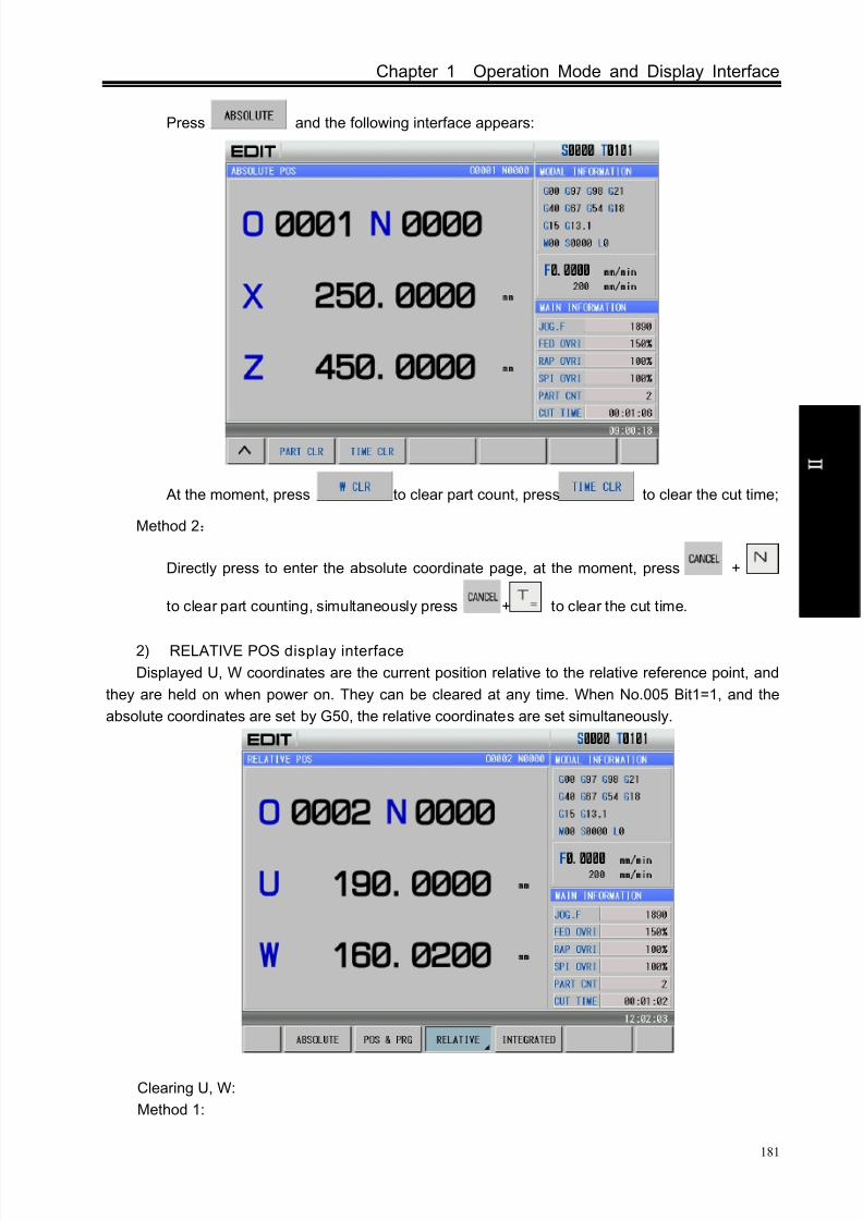
8/17/2019 980TDc CNC Turning Controller User Manual
http://slidepdf.com/reader/full/980tdc-cnc-turning-controller-user-manual 196/461
Chapter 1 Operation Mode and Display Interface
181
O p er a t i on
Press and the following interface appears:
At the moment, press to clear part count, press to clear the cut time;
Method 2:
Directly press to enter the absolute coordinate page, at the moment, press +
to clear part counting, simultaneously press + to clear the cut time.
2) RELATIVE POS display interface
Displayed U, W coordinates are the current position relative to the relative reference point, and
they are held on when power on. They can be cleared at any time. When No.005 Bit1=1, and the
absolute coordinates are set by G50, the relative coordinates are set simultaneously.
Clearing U, W:
Method 1:

8/17/2019 980TDc CNC Turning Controller User Manual
http://slidepdf.com/reader/full/980tdc-cnc-turning-controller-user-manual 197/461

8/17/2019 980TDc CNC Turning Controller User Manual
http://slidepdf.com/reader/full/980tdc-cnc-turning-controller-user-manual 198/461
Chapter 1 Operation Mode and Display Interface
183
O p er a t i on
Press and the following page is shown:
At the moment, press to clear X coordinate value, and press to clear
Z coordinate value;
Method 2:
Switch to the integrated coordinate page, simultaneously press + to clear X
machine coordinate value; meanwhile, press + to clear Z machine coordinate value.
Note 1: Clearing method is the same when many axes are enabled.
Note 2: Clearing operation is enabled only when each axis has no machine zero (No.0014 bit0 bit4 is set to
0) .
4) POS&PRG display interface
In POS&PRG interface, it displays ABSOLUTE, RELATIVE coordinate of the current
position (ABSOLUTE, DIST TO GO of current position and machine coordinates will be
displayed when No.180 BIT0 is set to 1) as well as 7 blocks of current program together. During
the program execution, the displayed blocks are refreshed dynamically and the cursor is located
in the block being executed.
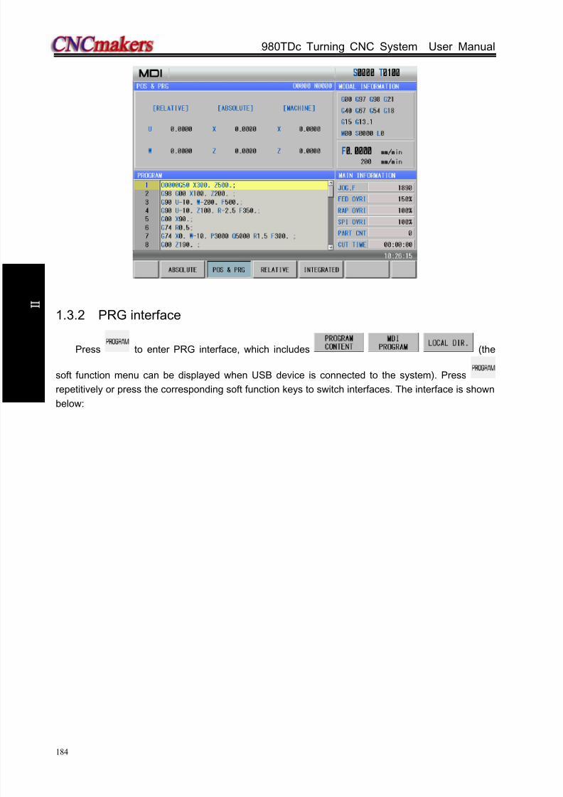
8/17/2019 980TDc CNC Turning Controller User Manual
http://slidepdf.com/reader/full/980tdc-cnc-turning-controller-user-manual 199/461
GSK980TDc Turning CNC System User Manual
184
O p er a t i on
1.3.2 PRG interface
Press to enter PRG interface, which includes (the
soft function menu can be displayed when USB device is connected to the system). Press
repetitively or press the corresponding soft function keys to switch interfaces. The interface is shown
below:
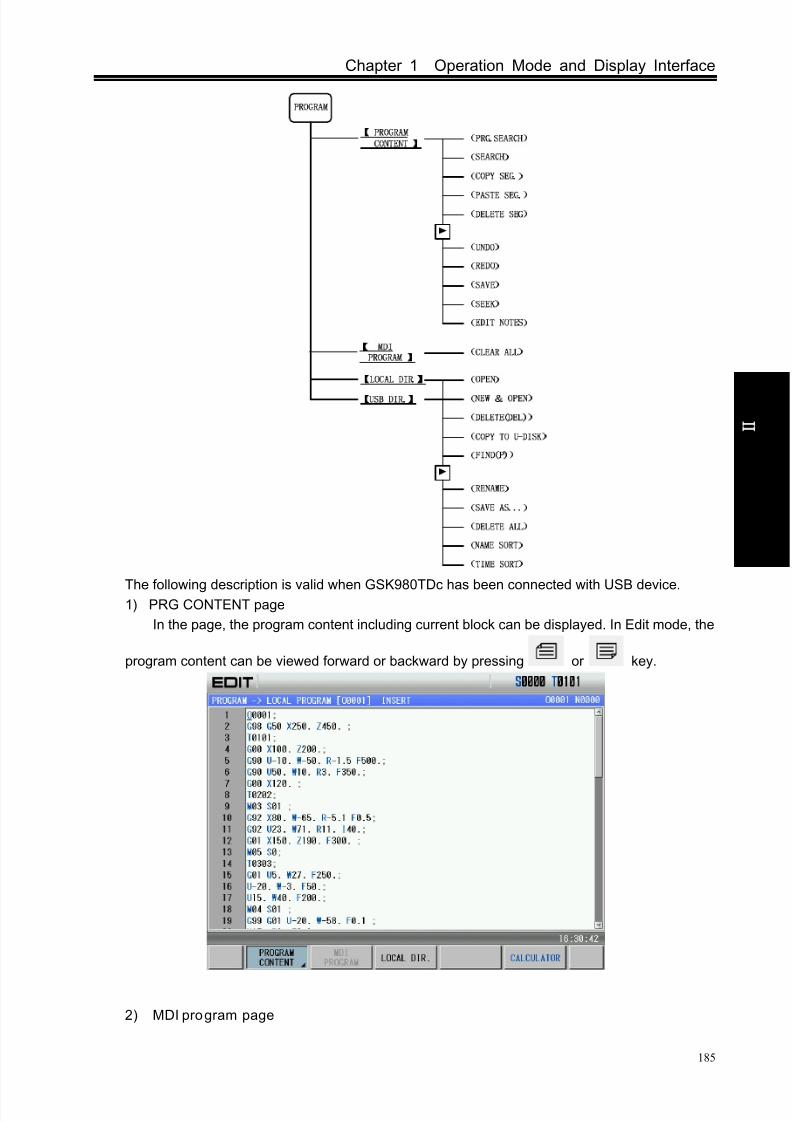
8/17/2019 980TDc CNC Turning Controller User Manual
http://slidepdf.com/reader/full/980tdc-cnc-turning-controller-user-manual 200/461
Chapter 1 Operation Mode and Display Interface
185
O p er a t i on
The following description is valid when GSK980TDc has been connected with USB device.1) PRG CONTENT page
In the page, the program content including current block can be displayed. In Edit mode, the
program content can be viewed forward or backward by pressing or key.
2) MDI program page

8/17/2019 980TDc CNC Turning Controller User Manual
http://slidepdf.com/reader/full/980tdc-cnc-turning-controller-user-manual 201/461
GSK980TDc Turning CNC System User Manual
186
O p er a t i on
In MDI mode, the page can be displayed, and is value when the corresponding soft function key is
pressed as follows:
3) Local directory page
Press to enter the local program page as follows:

8/17/2019 980TDc CNC Turning Controller User Manual
http://slidepdf.com/reader/full/980tdc-cnc-turning-controller-user-manual 202/461
Chapter 1 Operation Mode and Display Interface
187
O p er a t i on
Press to enter the next menu as follows:
4) U disk directory page

8/17/2019 980TDc CNC Turning Controller User Manual
http://slidepdf.com/reader/full/980tdc-cnc-turning-controller-user-manual 203/461
GSK980TDc Turning CNC System User Manual
188
O p er a t i on
Press to enter U disk directory page as follows:
Press to enter the next menu as follows:

8/17/2019 980TDc CNC Turning Controller User Manual
http://slidepdf.com/reader/full/980tdc-cnc-turning-controller-user-manual 204/461
Chapter 1 Operation Mode and Display Interface
189
O p er a t i on
1.3.3 TOOL OFFSET Interface
Press to enter the TOOL OFFSET interface which includes , ,
, (it enters the interface when No. 002 Bit0 is set to 1). Press
repetitively or corresponding keys to switch pages. The interface is shown below: .
1 TOOL OFFSET&WEAR interface
There are 5 pages and 33 offset & wear No. (No.000~No.032) available for user in the interface,
which can be shown as follows by pressing or key.

8/17/2019 980TDc CNC Turning Controller User Manual
http://slidepdf.com/reader/full/980tdc-cnc-turning-controller-user-manual 205/461
GSK980TDc Turning CNC System User Manual
190
O p er a t i on
When the valid axis number is more than 2, pressing or can display the tool offset &
wear pages of other three axes, which is shown below.
Note: The axis names of Y, the 4th
, the 5th
axis is defined by No.225.
2 MACRO interface
There are 25 pages in this interface, which can be shown by pressing or key. In
Macro window there are 600 (No.100~No.199 and No.500~No.999) macro variables which can be
specified by macro command or set directly by keypad. The public variable page is shown below:

8/17/2019 980TDc CNC Turning Controller User Manual
http://slidepdf.com/reader/full/980tdc-cnc-turning-controller-user-manual 206/461
Chapter 1 Operation Mode and Display Interface
191
O p er a t i on
The local variable page is shown below:
The system variable page is shown below:
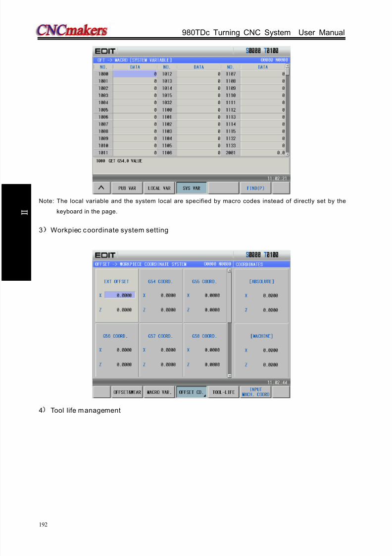
8/17/2019 980TDc CNC Turning Controller User Manual
http://slidepdf.com/reader/full/980tdc-cnc-turning-controller-user-manual 207/461
GSK980TDc Turning CNC System User Manual
192
O p er a t i on
Note: The local variable and the system local are specified by macro codes instead of directly set by the
keyboard in the page.
3 Workpiec coordinate system setting
4 Tool life management
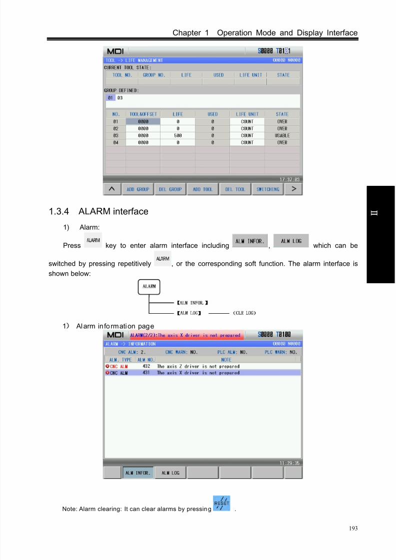
8/17/2019 980TDc CNC Turning Controller User Manual
http://slidepdf.com/reader/full/980tdc-cnc-turning-controller-user-manual 208/461
Chapter 1 Operation Mode and Display Interface
193
O p er a t i on
1.3.4 ALARM interface
1) Alarm:
Press key to enter alarm interface including , which can be
switched by pressing repetitively , or the corresponding soft function. The alarm interface is
shown below:
1
Alarm information page
Note: Alarm clearing: It can clear alarms by pressing .

8/17/2019 980TDc CNC Turning Controller User Manual
http://slidepdf.com/reader/full/980tdc-cnc-turning-controller-user-manual 209/461
GSK980TDc Turning CNC System User Manual
194
O p er a t i on
2 Alarm log page
1.3.5 Setting interface
Press to enter the SETTING interface including
which can be switched by pressing repetitively or corresponding soft keys. The interface is
shown below:
Note 1: *1, *2 soft function menus are displayed but *3 is not done when the cursor is in the switch setting
column in page; *1, *2 soft funct ion menus are not disp layed but *3 is done when the cursoris in the privilege setting o r parameter setting column;
Note 2: *4 soft function menu is displayed to (Copy to U disk) when the cursor is in CNC directory in
page; it is displayed to (Copy to CNC) when the cursor i s in U disk directory;
Note 3: *5 soft func tion menu is disp layed to (Select) when the system enters into page and theitem where the cursor is has not selected; it is d isplayed when the item has selected.
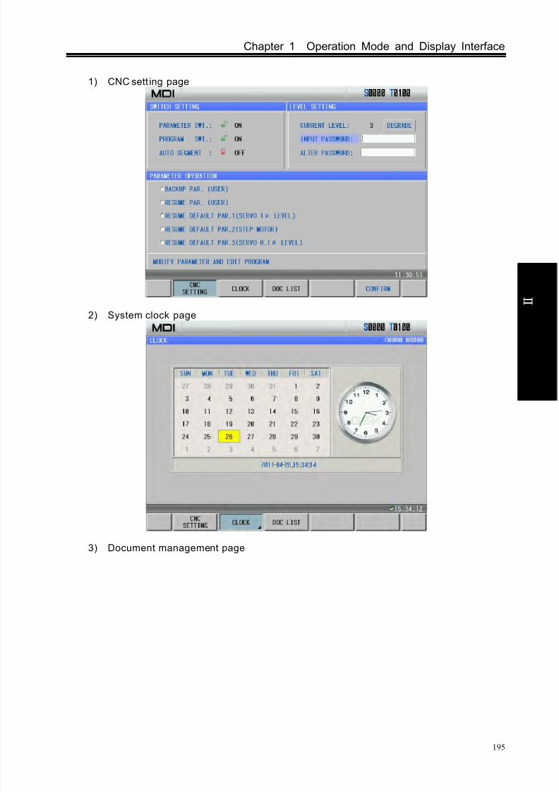
8/17/2019 980TDc CNC Turning Controller User Manual
http://slidepdf.com/reader/full/980tdc-cnc-turning-controller-user-manual 210/461
Chapter 1 Operation Mode and Display Interface
195
O p er a t i on
1) CNC sett ing page
2) System clock page
3) Document management page
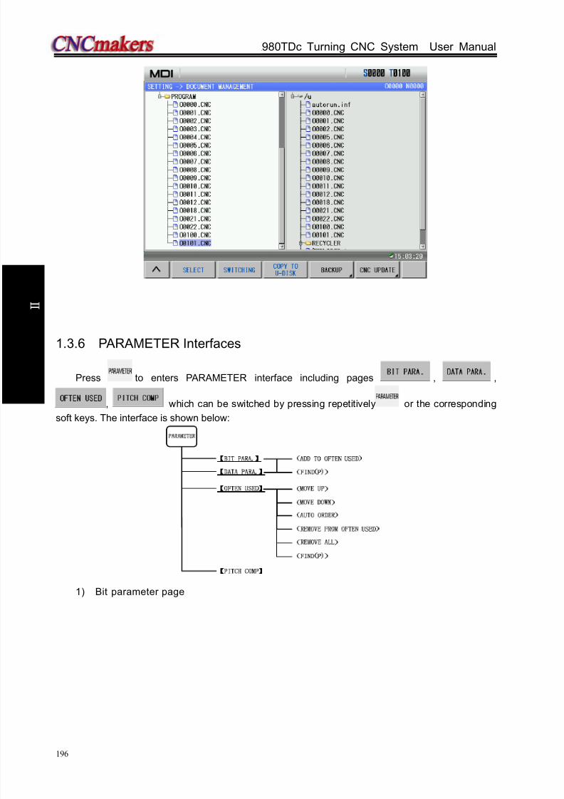
8/17/2019 980TDc CNC Turning Controller User Manual
http://slidepdf.com/reader/full/980tdc-cnc-turning-controller-user-manual 211/461
GSK980TDc Turning CNC System User Manual
196
O p er a t i on
1.3.6 PARAMETER Interfaces
Press to enters PARAMETER interface including pages , ,
, which can be switched by pressing repetitively or the corresponding
soft keys. The interface is shown below:
1) Bit parameter page

8/17/2019 980TDc CNC Turning Controller User Manual
http://slidepdf.com/reader/full/980tdc-cnc-turning-controller-user-manual 212/461
Chapter 1 Operation Mode and Display Interface
197
O p er a t i on
2) Data parameter page
3) Common used parameter page

8/17/2019 980TDc CNC Turning Controller User Manual
http://slidepdf.com/reader/full/980tdc-cnc-turning-controller-user-manual 213/461
GSK980TDc Turning CNC System User Manual
198
O p er a t i on
4) Pitch compensation parameter page
1.3.7 Diagnosis Interface
Press to enter diagnosis interface including pages which can be
switched by pressing repetitively or the corresponding soft keys. The interface is shown below:
:
1) System diagnos is page

8/17/2019 980TDc CNC Turning Controller User Manual
http://slidepdf.com/reader/full/980tdc-cnc-turning-controller-user-manual 214/461
Chapter 1 Operation Mode and Display Interface
199
O p er a t i on
The page is used to detect CNC interface signal and its inner run state. Please refer toINSTALLATION, Section 5.1.
2) System information page
1.3.8 Graph Interface
Press to enter GRAPH interface. The interface is shown below:
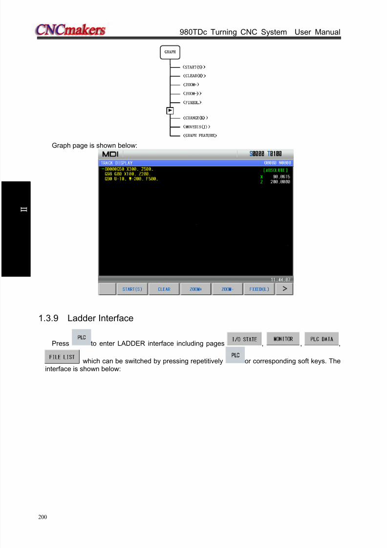
8/17/2019 980TDc CNC Turning Controller User Manual
http://slidepdf.com/reader/full/980tdc-cnc-turning-controller-user-manual 215/461
GSK980TDc Turning CNC System User Manual
200
O p er a t i on
Graph page is shown below:
1.3.9 Ladder Interface
Press to enter LADDER interface including pages , , ,
which can be switched by pressing repetitively or corresponding soft keys. Theinterface is shown below:

8/17/2019 980TDc CNC Turning Controller User Manual
http://slidepdf.com/reader/full/980tdc-cnc-turning-controller-user-manual 216/461
Chapter 1 Operation Mode and Display Interface
201
O p er a t i on
1) PLC I/O state page
The page can display PLC I/o state information.
2) Ladder monitor page
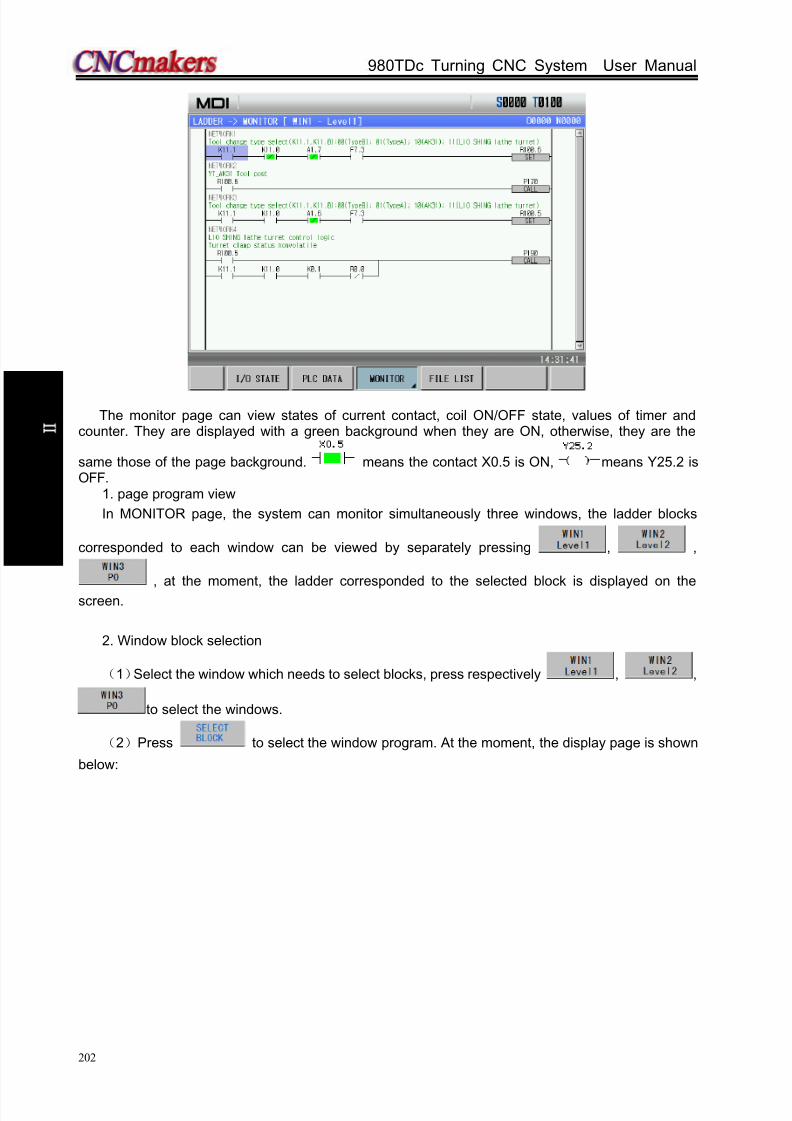
8/17/2019 980TDc CNC Turning Controller User Manual
http://slidepdf.com/reader/full/980tdc-cnc-turning-controller-user-manual 217/461
GSK980TDc Turning CNC System User Manual
202
O p er a t i on
The monitor page can view states of current contact, coil ON/OFF state, values of timer andcounter. They are displayed with a green background when they are ON, otherwise, they are the
same those of the page background. means the contact X0.5 is ON, means Y25.2 isOFF.
1. page program view
In MONITOR page, the system can monitor simultaneously three windows, the ladder blocks
corresponded to each window can be viewed by separately pressing , ,
, at the moment, the ladder corresponded to the selected block is displayed on the
screen.
2. Window block selection
(1)Select the window which needs to select blocks, press respectively , ,
to select the windows.
(2)Press to select the window program. At the moment, the display page is shown
below:
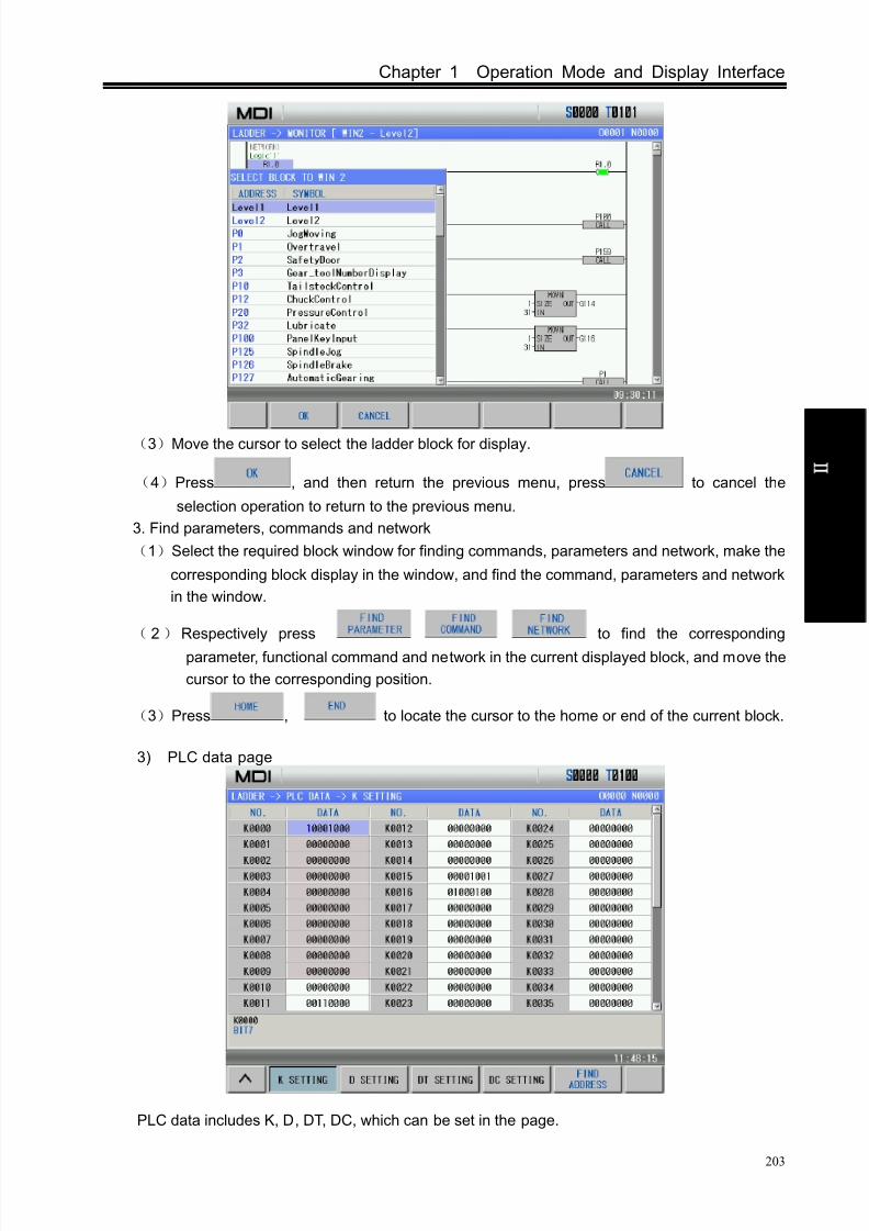
8/17/2019 980TDc CNC Turning Controller User Manual
http://slidepdf.com/reader/full/980tdc-cnc-turning-controller-user-manual 218/461
Chapter 1 Operation Mode and Display Interface
203
O p er a t i on
(3)Move the cursor to select the ladder block for display.
(4)Press , and then return the previous menu, press to cancel the
selection operation to return to the previous menu.
3. Find parameters, commands and network
(1)Select the required block window for finding commands, parameters and network, make the
corresponding block display in the window, and find the command, parameters and network
in the window.
( 2)Respectively press to find the corresponding
parameter, functional command and network in the current displayed block, and move the
cursor to the corresponding position.
(3)Press , to locate the cursor to the home or end of the current block.
3) PLC data page
PLC data includes K, D, DT, DC, which can be set in the page.
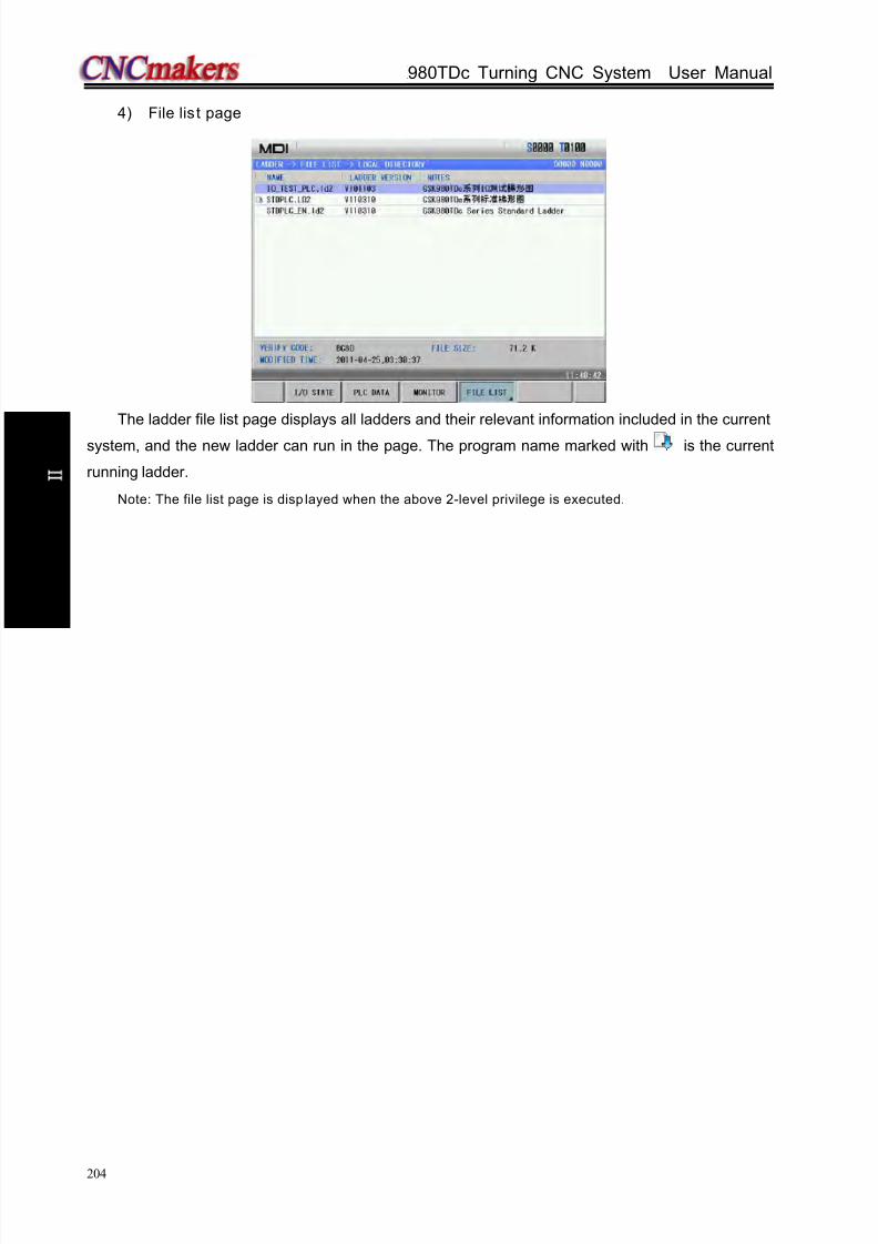
8/17/2019 980TDc CNC Turning Controller User Manual
http://slidepdf.com/reader/full/980tdc-cnc-turning-controller-user-manual 219/461
GSK980TDc Turning CNC System User Manual
204
O p er a t i on
4) File lis t page
The ladder file list page displays all ladders and their relevant information included in the current
system, and the new ladder can run in the page. The program name marked with is the current
running ladder.
Note: The file list page is disp layed when the above 2-level privilege is executed.

8/17/2019 980TDc CNC Turning Controller User Manual
http://slidepdf.com/reader/full/980tdc-cnc-turning-controller-user-manual 220/461
Chapter 2 Power ON/OFF And Protection
205
O p er a t i on
CHAPTER 2 POWER ON/OFF AND PROTECTION
2.1 System Power-on
Before GSK980TDc power on, the following items should be confirmed:1. The machine is in a normal state.
2. The power voltage conforms to the requirement of the machine.
3. The connection is correct and secure.
The following window is displayed after GSK980TDc is turned on:
The current position (ABSOLUTE POS) page is displayed after GSK980TDc automatic detectionand initiation are finished.
2.2 System Power-of f
Before power is off, ensure that:
1. The feed axes of the CNC is at stop;
2. Miscellaneous functions (spindle, cooling etc.) are OFF;
3. Cut off CNC power prior to machine power cutting off.
Note: Please refer to the machine manufacturer’s manual about turn-off the machine’s power supply.
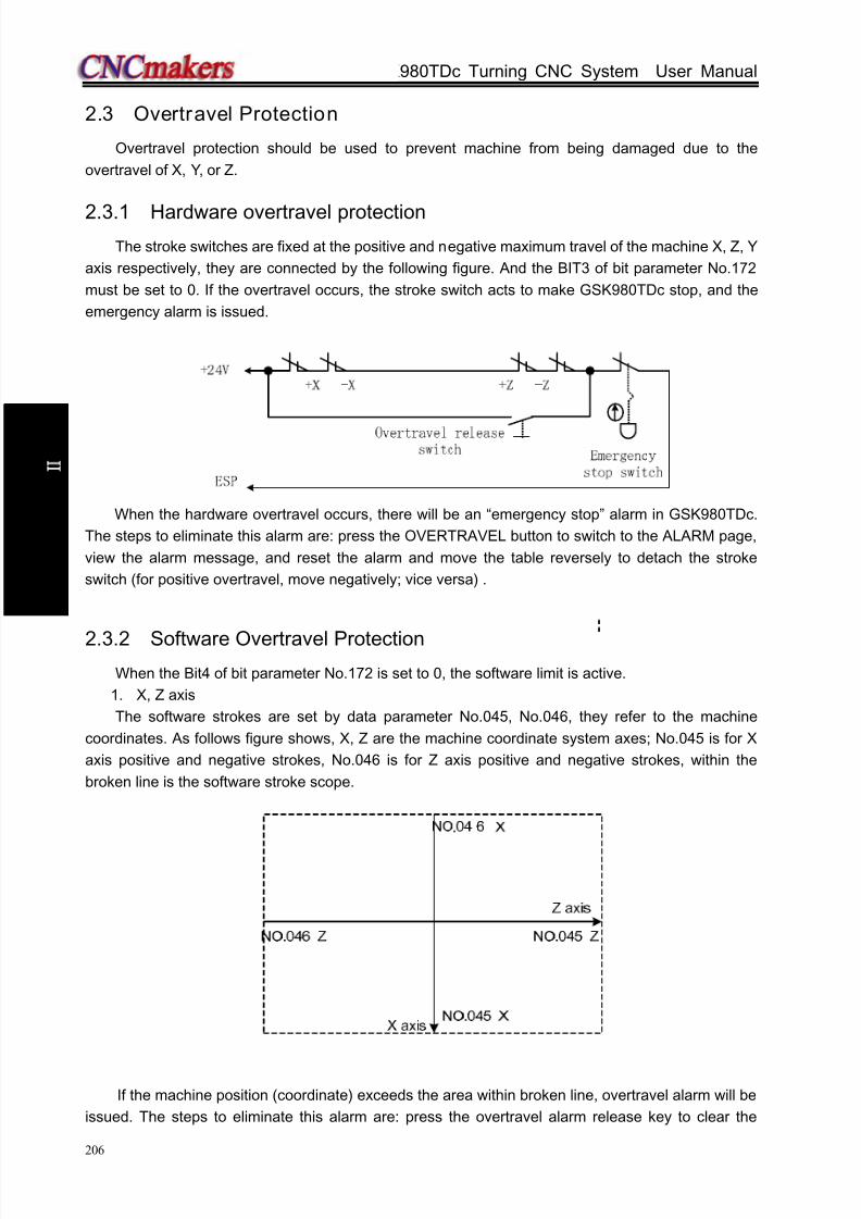
8/17/2019 980TDc CNC Turning Controller User Manual
http://slidepdf.com/reader/full/980tdc-cnc-turning-controller-user-manual 221/461
GSK980TDc Turning CNC System User Manual
206
O p er a t i on
2.3 Overtravel Protection
Overtravel protection should be used to prevent machine from being damaged due to the
overtravel of X, Y, or Z.
2.3.1 Hardware overtravel protectionThe stroke switches are fixed at the positive and negative maximum travel of the machine X, Z, Y
axis respectively, they are connected by the following figure. And the BIT3 of bit parameter No.172
must be set to 0. If the overtravel occurs, the stroke switch acts to make GSK980TDc stop, and the
emergency alarm is issued.
When the hardware overtravel occurs, there will be an “emergency stop” alarm in GSK980TDc.
The steps to eliminate this alarm are: press the OVERTRAVEL button to switch to the ALARM page,
view the alarm message, and reset the alarm and move the table reversely to detach the stroke
switch (for positive overtravel, move negatively; vice versa) .
2.3.2 Software Overtravel ProtectionWhen the Bit4 of bit parameter No.172 is set to 0, the software limit is active.
1. X, Z axis
The software strokes are set by data parameter No.045, No.046, they refer to the machine
coordinates. As follows figure shows, X, Z are the machine coordinate system axes; No.045 is for X
axis positive and negative strokes, No.046 is for Z axis positive and negative strokes, within the
broken line is the software stroke scope.
If the machine position (coordinate) exceeds the area within broken line, overtravel alarm will be
issued. The steps to eliminate this alarm are: press the overtravel alarm release key to clear the
8/17/2019 980TDc CNC Turning Controller User Manual
http://slidepdf.com/reader/full/980tdc-cnc-turning-controller-user-manual 222/461
Chapter 2 Power ON/OFF And Protection
207
O p er a t i on
alarm, then moves reversely (for positive overtravel, move out negatively; vice versa).
2. Additional axis
The stroke range setting is the same that of the basic axis. When the additional axis is enabled,
No. 045, No.046 displays stroke range parameter of the corresponding additional axis.
2.4 Emergency Operation
During the machining, some unexpected incidents may occur because of the user programming,
operation and product fault etc. So the GSK980TDc should be stopped immediately for these
incidents. This section mainly describes the resolutions that the system is capable of under the
emergency situation. Please see the relative explanation on these resolutions under the emergency
by machine manufacturer.
2.4.1 Reset
Press key to reset GSK980TDc system when there are abnormal output and axis
operations:
1 All axes motion stops;
2 M, S function output is inactive (the parameter sets whether the system automatically cuts off
signals of spindle rotation, lubricating, cooling by pressing key, defined by PLC
ladder);
3 Automatic run ends, modal function and state remain.
2.4.2 Emergency stop
During machine running, if the emergency button is pressed under the dangerous or emergent
situation (external SP signal active), the CNC system enters into emergency status and the machine
movement is stopped immediately. All the outputs such as the spindle running, cooling are cut off. If
the emergency button is released, the emergency alarm is cancelled and the CNC resets. Its circuit
wiring is shown in Section 2.3.1 of the Chapter.
Note 1: Ensure the fault is eliminated before the emergency alarm is cancelled.
Note 2: Pressing down the Emergency button prior to power on or off may alleviate the electric shock to the
machine system.
Note 3: Re-perform the machine zero return to get the correct position coordinate after the emergency alarm
is cancelled (machine zero return is forbidden if there is no machine zero on the machine.).
Note 4: Only Bit3 of the bit parameter No.172 is set to 0, is the external emergency stop active.
2.4.3 Feed hold
Press key during the machine running to make the running pause. However, in threading
cutting, tapping cycle state, the function cannot stop the running immediately.
2.4.4 Power-off
Under the dangerous or emergency situations during the machine running, the machine power

8/17/2019 980TDc CNC Turning Controller User Manual
http://slidepdf.com/reader/full/980tdc-cnc-turning-controller-user-manual 223/461
GSK980TDc Turning CNC System User Manual
208
O p er a t i on
should be cut off immediately to avoid the accidents. But it should be noted that there may be a large
error between the CNC coordinates displayed and the actual position. So the toolsetting operation
should be performed again.
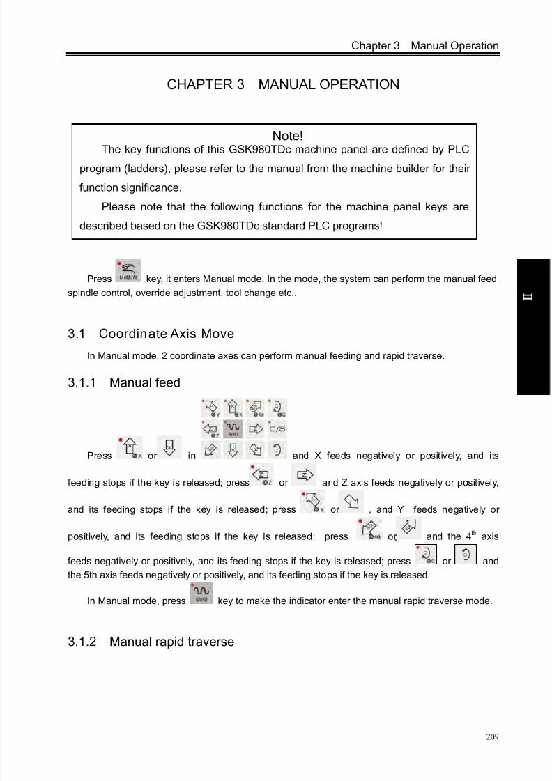
8/17/2019 980TDc CNC Turning Controller User Manual
http://slidepdf.com/reader/full/980tdc-cnc-turning-controller-user-manual 224/461
Chapter 3 Manual Operation
209
O p er a t i on
CHAPTER 3 MANUAL OPERATION
Press key, it enters Manual mode. In the mode, the system can perform the manual feed,
spindle control, override adjustment, tool change etc..
3.1 Coordinate Axis Move
In Manual mode, 2 coordinate axes can perform manual feeding and rapid traverse.
3.1.1 Manual feed
Press or in and X feeds negatively or positively, and its
feeding stops if the key is released; press or and Z axis feeds negatively or positively,
and its feeding stops if the key is released; press or , and Y feeds negatively or
positively, and its feeding stops if the key is released; press or and the 4th axis
feeds negatively or positively, and its feeding stops if the key is released; press or and
the 5th axis feeds negatively or positively, and its feeding stops if the key is released.
In Manual mode, press key to make the indicator enter the manual rapid traverse mode.
3.1.2 Manual rapid traverse
Note!The key functions of this GSK980TDc machine panel are defined by PLC
program (ladders), please refer to the manual from the machine builder for their
function significance.
Please note that the following functions for the machine panel keys are
described based on the GSK980TDc standard PLC programs!
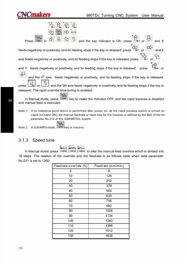
8/17/2019 980TDc CNC Turning Controller User Manual
http://slidepdf.com/reader/full/980tdc-cnc-turning-controller-user-manual 225/461
GSK980TDc Turning CNC System User Manual
210
O p er a t i on
Press in and the key indicator is ON; press or and X
feeds negatively or positively, and its feeding stops if the key is released; press or and Z
axis feeds negatively or positively, and its feeding stops if the key is released; press or ,
and Y feeds negatively or positively, and its feeding stops if the key is released; press or
and the 4th axis feeds negatively or positively, and its feeding stops if the key is released;
press or and the 5th axis feeds negatively or positively, and its feeding stops if the key is
released. The rapid override time-tuning is enabled.
In Manual mode, press key to make the indicator OFF, and the rapid traverse is disabledand manual feed is executed.
Note 1: If no reference point return is performed after power on, as the rapid traverse switch is turned on
(rapid ind icator ON), the manual feedrate or rapid rate for the traverse is defined by the Bit0 of the bit
parameter No.012 of this GSK980TDc system.
Note 2: In Edit/MPG mode, key is inactive.
3.1.3 Speed tune
In Manual mode, press , , to alter the manual feed override which is divided into
16 steps. The relation of the override and the feedrate is as follows table when data parameter
No.031 is set to 1260:
Feedrate override (%) Feedrate (mm/min)
0 0
10 126
20 252
30 378
40 504
50 630
60 756
70 882
80 1008
90 1134
100 1260
110 1386
120 1512
130 1638
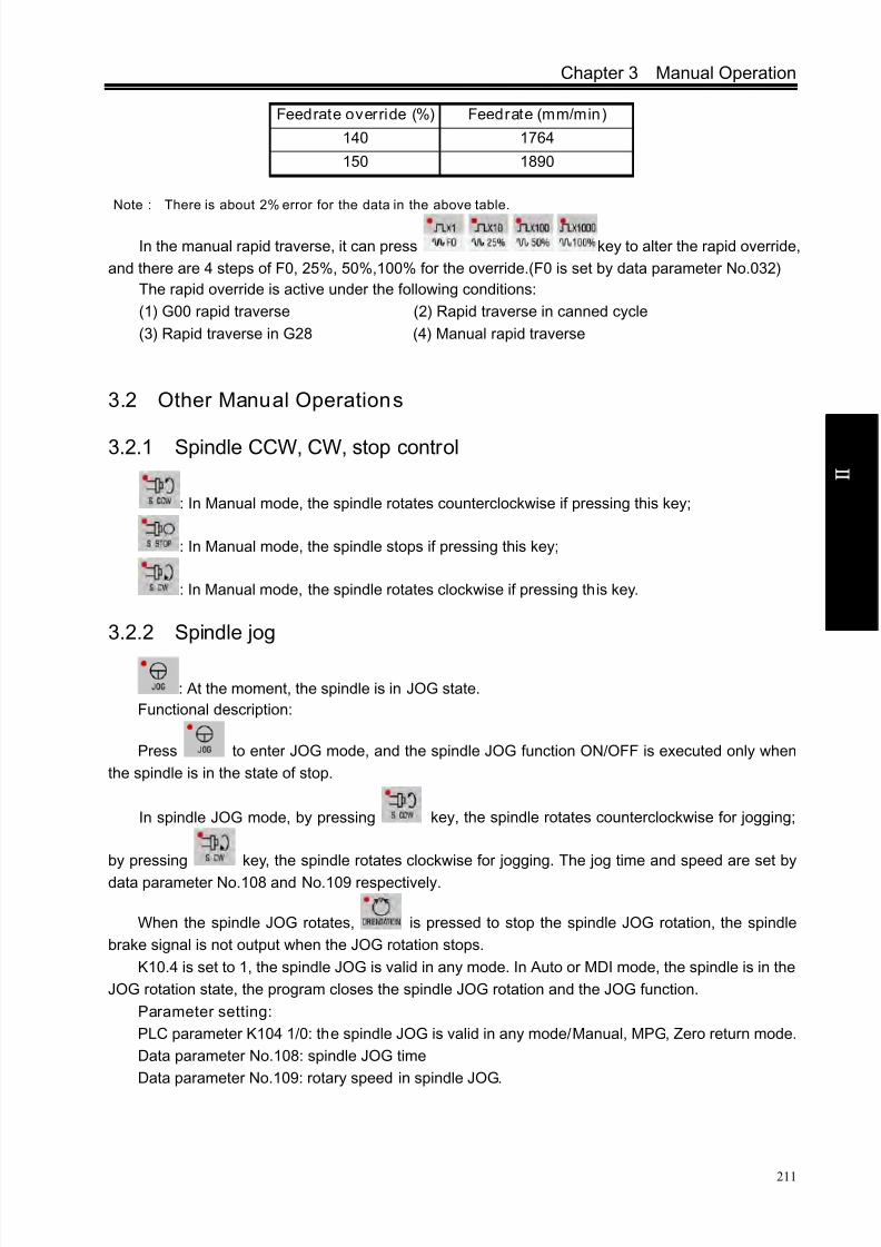
8/17/2019 980TDc CNC Turning Controller User Manual
http://slidepdf.com/reader/full/980tdc-cnc-turning-controller-user-manual 226/461
Chapter 3 Manual Operation
211
O p er a t i on
Feedrate override (%) Feedrate (mm/min)
140 1764
150 1890
Note : There is about 2% error for the data in the above table.
In the manual rapid traverse, it can press key to alter the rapid override,
and there are 4 steps of F0, 25%, 50%,100% for the override.(F0 is set by data parameter No.032)
The rapid override is active under the following conditions:
(1) G00 rapid traverse (2) Rapid traverse in canned cycle
(3) Rapid traverse in G28 (4) Manual rapid traverse
3.2 Other Manual Operations
3.2.1 Spindle CCW, CW, stop control
: In Manual mode, the spindle rotates counterclockwise if pressing this key;
: In Manual mode, the spindle stops if pressing this key;
: In Manual mode, the spindle rotates clockwise if pressing this key.
3.2.2 Spindle jog
: At the moment, the spindle is in JOG state.
Functional description:
Press to enter JOG mode, and the spindle JOG function ON/OFF is executed only when
the spindle is in the state of stop.
In spindle JOG mode, by pressing key, the spindle rotates counterclockwise for jogging;
by pressing key, the spindle rotates clockwise for jogging. The jog time and speed are set by
data parameter No.108 and No.109 respectively.
When the spindle JOG rotates, is pressed to stop the spindle JOG rotation, the spindle
brake signal is not output when the JOG rotation stops.
K10.4 is set to 1, the spindle JOG is valid in any mode. In Auto or MDI mode, the spindle is in the
JOG rotation state, the program closes the spindle JOG rotation and the JOG function.
Parameter setting:
PLC parameter K104 1/0: the spindle JOG is valid in any mode/Manual, MPG, Zero return mode.
Data parameter No.108: spindle JOG time
Data parameter No.109: rotary speed in spindle JOG.

8/17/2019 980TDc CNC Turning Controller User Manual
http://slidepdf.com/reader/full/980tdc-cnc-turning-controller-user-manual 227/461
GSK980TDc Turning CNC System User Manual
212
O p er a t i on
3.2.3 Cooling control
: In Manual mode, press this key, the cooling is switched on/off.
Parameter setting: PLC parameter K10.1 1/0: the spindle lubricating and cooling output
remains/closes in reset.
3.2.4 Lubricating control
Function description:
1. Non-automatic lubricating (DT017 =0)
When PLC DT013=0, it is the lubricating turn output. Pressing the can execute the
output. And the lubricating is cancelled by pressing it again. M32 is to execute lubricating output, and
M33 is to cancel lubricating output.
When PLC DT013 >1, it is timing lubricating output. Pressing the can execute the output.
And it is cancelled after a setting time by data parameter DT013; M32 is to execute lubricating output
and the output is cancelled after a time set by DT013. If the setting time is not yet up, M33 is executed
to cancel the lubricating output.
2. Automatic lubricating (DT017>0)
For automatic lubricating, the system executes the lubricating in the time set by DT017 and the
stops the output. After lubricating interval time set by DT016, the output is done again, it does
repetitively like this. During the automatic lubricating, M32, M33 codes as well as the key areall active.
Parameter setting:
PLC parameter: K10.1 1/0: the spindle lubricating/cooling output remains/closes in reset;
PLC parameter:K16.2 1/0: whether the lubricating outputs in power-on when the automatic
lubricating is valid;
PLC data DT005: M execution duration(ms);
PLC data DT013: lubricating start time (0-60000ms)(0:lubricating time is not limited);
PLC data: DT016 automatic lubricating interval time (ms);
PLC data: DT017: automatic lubricating output time (ms).
3.2.5 Chuck control
: press it to switch the chuck releasing/clamping in any mode.
Function description:
When the chuck control is invalid, the system alarms in executing the chuck control M command;
When the system checks the chuck clamping (K12.1=1), the spindle cannot be started when the
chuck is not clamped, and the chuck cannot be released after the spindle is started;
When using the input signal controls the chuck operation, the spindle should stop and delay thetime set by DT21, the control is valid.
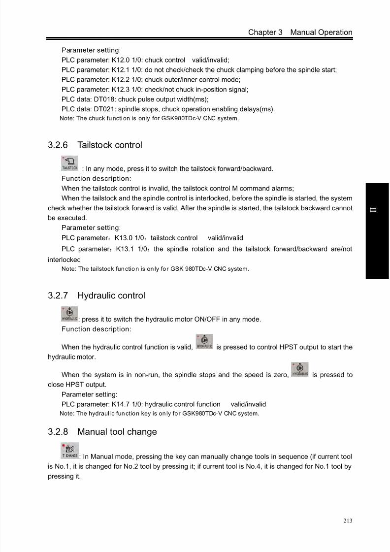
8/17/2019 980TDc CNC Turning Controller User Manual
http://slidepdf.com/reader/full/980tdc-cnc-turning-controller-user-manual 228/461
Chapter 3 Manual Operation
213
O p er a t i on
Parameter setting:
PLC parameter: K12.0 1/0: chuck control valid/invalid;
PLC parameter: K12.1 1/0: do not check/check the chuck clamping before the spindle start;
PLC parameter: K12.2 1/0: chuck outer/inner control mode;
PLC parameter: K12.3 1/0: check/not chuck in-position signal;
PLC data: DT018: chuck pulse output width(ms);
PLC data: DT021: spindle stops, chuck operation enabling delays(ms).
Note: The chuck function is only for GSK980TDc-V CNC system.
3.2.6 Tailstock control
: In any mode, press it to switch the tailstock forward/backward.
Function description:
When the tailstock control is invalid, the tailstock control M command alarms;
When the tailstock and the spindle control is interlocked, before the spindle is started, the system
check whether the tailstock forward is valid. After the spindle is started, the tailstock backward cannot
be executed.
Parameter setting:
PLC parameter :K13.0 1/0:tailstock control valid/invalid
PLC parameter :K13.1 1/0:the spindle rotation and the tailstock forward/backward are/not
interlocked
Note: The tailstock function is on ly for GSK 980TDc-V CNC system.
3.2.7 Hydraulic control
: press it to switch the hydraulic motor ON/OFF in any mode.
Function description:
When the hydraulic control function is valid, is pressed to control HPST output to start the
hydraulic motor.
When the system is in non-run, the spindle stops and the speed is zero, is pressed to
close HPST output.Parameter setting:
PLC parameter: K14.7 1/0: hydraulic control function valid/invalid
Note: The hydraulic function key is on ly for GSK980TDc-V CNC system.
3.2.8 Manual tool change
: In Manual mode, pressing the key can manually change tools in sequence (if current tool
is No.1, it is changed for No.2 tool by pressing it; if current tool is No.4, it is changed for No.1 tool by
pressing it.

8/17/2019 980TDc CNC Turning Controller User Manual
http://slidepdf.com/reader/full/980tdc-cnc-turning-controller-user-manual 229/461
GSK980TDc Turning CNC System User Manual
214
O p er a t i on
3.2.9 Spindle override
In Manual mode, if the spindle speed is controlled by analog voltage output, the spindle speed
may be overrided.
Pressing , can change the spindle speed in real-time to adjust 8 steps of 50%~120% of the spindle override.

8/17/2019 980TDc CNC Turning Controller User Manual
http://slidepdf.com/reader/full/980tdc-cnc-turning-controller-user-manual 230/461
Chapter 4 MPG/Step Operation
215
O p er a t i on
CHAPTER 4 MPG/STEP OPERATION
In MPG/Step mode, the machine moves by a specified increment.
4.1 Step Feed
Set the system parameter No.001 Bit3 to 0, and press key to enter the STEP working
mode, it displays as follows:
4.1.1 Increment selection
Press to select the move increment, the increment will be shown in the
page. When the BIT7(SINC) of K016 is 1, step width value is inactive; when the BIT7 is 0,
are all active. For example, to press key, the window is shown as
follows:
Note!The key functions of this GSK980TDc machine panel are defined by PLC
program (ladders), please refer to the manuals by the machine builder for their
significance.
Please note that the following description for the key functions in this chapter
is based on the GSK980TDc standard PLC program!

8/17/2019 980TDc CNC Turning Controller User Manual
http://slidepdf.com/reader/full/980tdc-cnc-turning-controller-user-manual 231/461
GSK980TDc Turning CNC System User Manual
216
V ol um e
O p er a t i on
4.1.2 Moving direction selection
Pressing or key once can move X negatively or positively by a step increment;
pressing or key once can move Z negatively or positively by a step increment;
pressing or key once can move Y negatively or positively by a step increment.
4.2 MPG(handwheel) Feed
Set the BIT3 of the system parameter No.001 to 1, and press key to enter the MPG mode,
it displays as follows:

8/17/2019 980TDc CNC Turning Controller User Manual
http://slidepdf.com/reader/full/980tdc-cnc-turning-controller-user-manual 232/461
Chapter 4 MPG/Step Operation
217
O p er a t i on
The MPG figure is shown as follows:
The handwheel (MPG) figu re
4.2.1 Increment selection
Press key to select the move increment, the increment will be shown in
the window. When the BIT7(SINC) of PLC K016 is 1, step is inactive; when BIT7 is 0,
are all active. For example, to press key, the window is shown as
follows:
4.2.2 Moving axis and direction selection
In MPG mode, press , , , , , key, the corresponding axis will
be selected. For example, press key and the window is shown below:

8/17/2019 980TDc CNC Turning Controller User Manual
http://slidepdf.com/reader/full/980tdc-cnc-turning-controller-user-manual 233/461
GSK980TDc Turning CNC System User Manual
218
V ol um e
O p er a t i on
The MPG feed direction is defined by its rotation direction. Generally, the MPG CW is for positive
feed, and CCW for negative feed. In case of that MPG CW is for negative feed, CCW for positive feed,
it may exchange the A, B signals of the MPG terminals. Bit0~Bit4 of NO. 013 selects the feed
direction of MPG rotation.
4.2.3 Other operations
1 Spindle CCW, CW, stop control
: In Manual mode, the spindle rotates counterclockwise if pressing this key;
: In Manual mode, the spindle stops if pressing this key;
: In Manual mode, the spindle rotates clockwise if pressing this key.
2
Spindle Jog
: at the moment, the spindle is in JOG working mode.
In spindle Jog mode, pressing can rotate counterclockwise for jogging; pressingcan rotate clockwise for jog. The jogging time and speed are set by DT12 and No.109 respectively.
Referred to Section 3.2.2.
3 Cooling control
Refer to OPERATION, Section 3.2.3
4 Lubricating control
Refer to OPERATION, Section 3.2.4
5
Chuck control
Refer to OPERATION, Section 3.2.5
6 Tailstock control
Refer to OPERATION, Section 3.2.6

8/17/2019 980TDc CNC Turning Controller User Manual
http://slidepdf.com/reader/full/980tdc-cnc-turning-controller-user-manual 234/461
Chapter 4 MPG/Step Operation
219
O p er a t i on
7 Hydraulic control
Refer to II OPERATION, Section 3.2.7
8) Manual tool change
: In MPG/Step mode, press it to change tools orderly.
9) Spindle override tune
In MPG/Step mode, if the spindle speed is controlled by analog voltage output, the spindle speed
may be overrided.
Pressing , can change the spindle speed in real-time to adjust 8 steps of 50%~120
% of the spindle override
4.2.4 Explanation items
The correspondence of the handwheel scale to the machine moving amount is as follows table:
Moving amount of each MPG scale
MPG increment 0.001 0.01 0.1 1
Specified coordinate value 0.001mm 0.01mm 0.1mm 1mm
(Taking example of the least input increment 0.001mm)
Note 1: The MPG increment is related to the system’s current metric/inch input state and the system’s least
input increment.
Note 2: The MPG speed cannot be more than 5r/s, otherwise, the scale value is inconsistent with the
movement amount.

8/17/2019 980TDc CNC Turning Controller User Manual
http://slidepdf.com/reader/full/980tdc-cnc-turning-controller-user-manual 235/461
GSK980TDc Turning CNC System User Manual
220
O p er a t i on
CHAPTER 5 MDI OPERATION
In MDI mode, the operations of parameter setting, code words input and execution can be
performed.
5.1 Block Input
Select MDI mode to enter PROGRAM->MDI page, to input an block G50 X50 Z100, the steps
are shown below:
1) Press key to enter MDI mode;
2) Press , and then press to enter MDI program page below:
The page is shown as follows after above operations are completed:
Note!The key functions of this GSK980TDc machine panel are defined by PLC
program (ladders), please refer to the manuals by the machine builder for their
significance.
Please note that the following description for the key functions in this chapter is
based on the GSK980TDc standard PLC program!
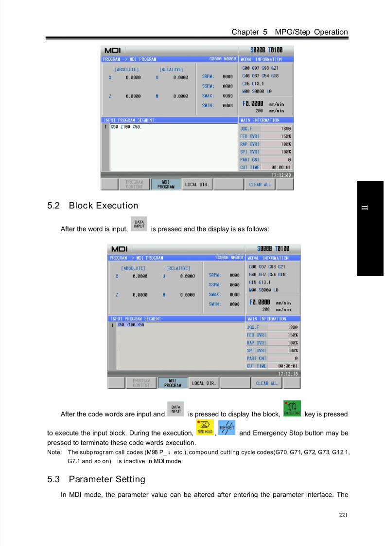
8/17/2019 980TDc CNC Turning Controller User Manual
http://slidepdf.com/reader/full/980tdc-cnc-turning-controller-user-manual 236/461
Chapter 5 MPG/Step Operation
221
O p er a t i on
5.2 Block Execut ion
After the word is input, is pressed and the display is as follows:
After the code words are input and is pressed to display the block, key is pressed
to execute the input block. During the execution, , and Emergency Stop button may be
pressed to terminate these code words execution.
Note: The subprogram call codes (M98 P_ etc.), compound cutting cycle codes(G70, G71, G72, G73, G12.1,
G7.1 and so on) is inactive in MDI mode.
5.3 Parameter Sett ing
In MDI mode, the parameter value can be altered after entering the parameter interface. The

8/17/2019 980TDc CNC Turning Controller User Manual
http://slidepdf.com/reader/full/980tdc-cnc-turning-controller-user-manual 237/461
GSK980TDc Turning CNC System User Manual
222
O p er a t i on
detailed is referred to OPERATION, Chapter 10.
5.4 Data Alteration
In PRG->MDI page, if there is an error during words inputting before executing the input block,
is pressed to cancel the display to alter the program, or is pressed to clear all the
input, then correct re-inputting is executed.
5.5 Other Operations
1. Adjusting spindle override
In MDI mode, the spindle speed can be adjusted when the analog voltage output controls the
spindle speed.
Pressing , can adjust the spindle override to change the spindle speed, which can
realize the 8 steps adjustment in real-time from 50%~120%.
2.Adjusting rapid override
Pressing can execute the rapid traverse, which can realize the 4 stepsadjustment in real-time.
3. Adjusting feedrate
In MDI mode, pressing , , can adjust the federate override to change thefederate, which can realize 16 steps adjustment from 0~150%.
4. Feedrate override is available.

8/17/2019 980TDc CNC Turning Controller User Manual
http://slidepdf.com/reader/full/980tdc-cnc-turning-controller-user-manual 238/461
Chapter 6 Program Edit and Management
223
O p er a t i on
CHAPTER 6 PROGRAM EDIT AND MANAGEMENT
In Edit mode, a program can be created, selected, altered, copied and deleted, and the
bidirectional communication of CNC to CNC, or CNC to PC can also be done.
To prevent the program to be altered or deleted accidentally, a program switch is set up for this
GSK980TDc system. And it must be turned on before program editing. Please see details in Section
10.1.1 of the part.
The system provides multi-level user permission to facilitate the management. More than 4 levels
(4 level, 3 level) can open the program switch to edit programs. See OPERATION, Section 10.1.2 .
6.1 Program Creation
6.1.1 Creating a block number
In the program, a block number can be added or not, the program is executed by the sequence.
When the “AUTO SEG” switch in SWITCH SETTING window is OFF, CNC doesn’t generate the block
number automatically, but the blocks may be numbered manually.
When the “AUTO SEG” switch in SWITCH SETTING window is ON, CNC generates the block
number automatically, it automatically generates the next block number by pressing or
in editing. The block number increment is set by the CNC data parameter No.042. (See details in
Section 10.1.1 of this part.)
6.1.2 Inputting a program
Press to enter the Edit mode. Press to enter the Program interface, create a
machining program before inputting a machining program. The creating method is shown below:
Method 1:
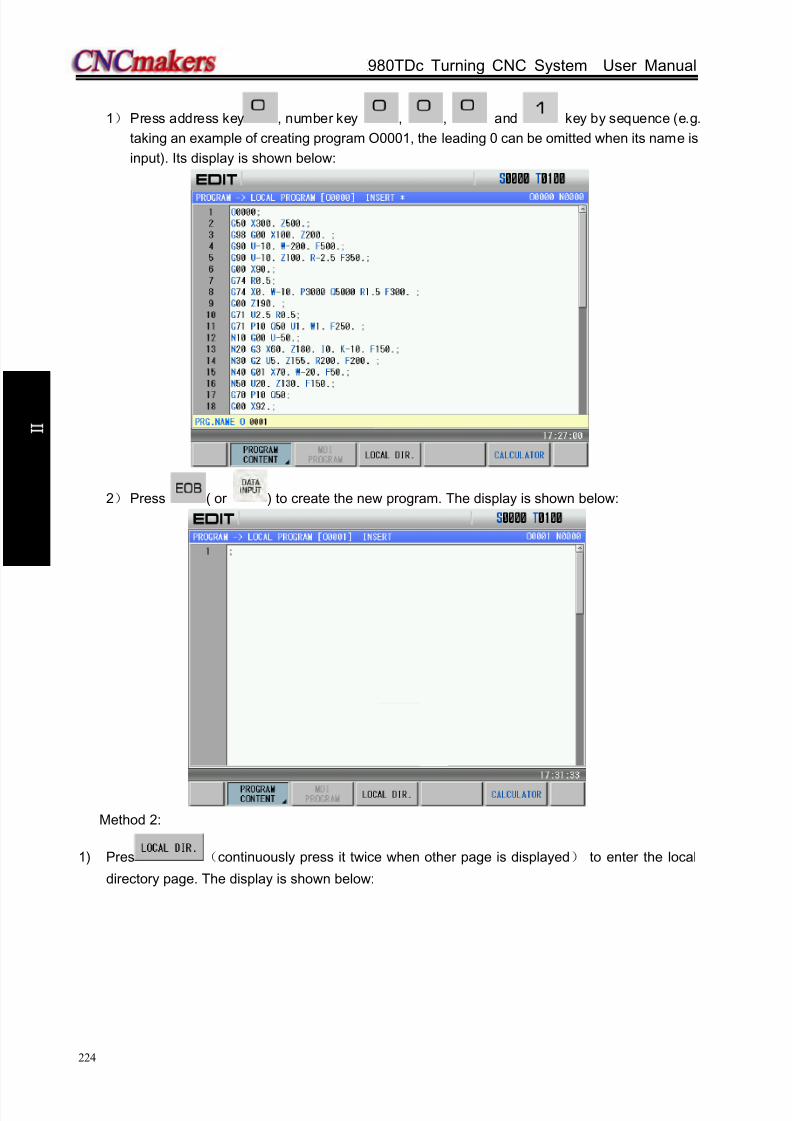
8/17/2019 980TDc CNC Turning Controller User Manual
http://slidepdf.com/reader/full/980tdc-cnc-turning-controller-user-manual 239/461
GSK980TDc Turning CNC System User Manual
224
O p er a t i on
1) Press address key , number key , , and key by sequence (e.g.
taking an example of creating program O0001, the leading 0 can be omitted when its name is
input). Its display is shown below:
2) Press ( or ) to create the new program. The display is shown below:
Method 2:
1) Pres (continuously press it twice when other page is displayed) to enter the local
directory page. The display is shown below:

8/17/2019 980TDc CNC Turning Controller User Manual
http://slidepdf.com/reader/full/980tdc-cnc-turning-controller-user-manual 240/461
Chapter 6 Program Edit and Management
225
O p er a t i on
2) Press ,input orderly , , , in the pop-up dialog box(taking
example of creating O0001, the leading zero can be omitted when it is input). It display is shown
below:
3) Press ( or ) to create the new program. The current page is automatically switched
into the program content page. Its display is shown below:

8/17/2019 980TDc CNC Turning Controller User Manual
http://slidepdf.com/reader/full/980tdc-cnc-turning-controller-user-manual 241/461
GSK980TDc Turning CNC System User Manual
226
O p er a t i on
Note: When a program is needed to create, the input program name exists , the system opens the file,
otherwise, it automatically create a new one.
Input the edited part program one by one, the character will be displayed on the screen
immediately as it is input(as for compound key, press this key repeatedly for alternate input),
after a block is finished, press or to terminate it.
Note: The unexpected pow er-off when the program is inpu t, the program being edited cannot be saved.
6.1.3 Searching a character
1. Scanning: To scan the character one by one by cursor
1) Press key to enter the Edit mode, then press key to enter the PRG CONTENT
window;
2) Press key, the cursor shifts a row upward; if the number of the column where the
cursor locates is over the total columns of the previous row, the cursor moves to the previous block
end (at “;” sign) after key is pressed;
3) Press key, the cursor shifts a row downward; if the number of the column where the
cursor locates is over the total columns of the next row, the cursor moves to the next block end (at “;”
sign) after the key is pressed;
4) Press key, the cursor shifts a column to the right; if the cursor locates at the row end,
it moves to the head of the next block;
5) Press key, the cursor shifts a column to the left; if the cursor locates at the row head,
it moves to the end of the next block;
6) Press key to window upward, the cursor moves to the 1st row and 1
st column of the

8/17/2019 980TDc CNC Turning Controller User Manual
http://slidepdf.com/reader/full/980tdc-cnc-turning-controller-user-manual 242/461
Chapter 6 Program Edit and Management
227
O p er a t i on
previous window, if it windows to the head of the program, the cursor moves to the 2nd
row and 1st
column;
7) Press key to window downward, the cursor moves to the 1st row and 1st column of
the next window, if it windows to the end of the program, the cursor moves to the last row and 1st
column of the program;
2. Finding: To search for the specified character upward or downw ard from the cursor
current location
The steps of finding is as follows:
1) Press to enter Edit mode, and press key to enter the PRG CONTENT window;
2) Press , and input the required characters to be searched(can input one block). For
example, finding “G00” page is shown below:
4) Press key ( or is determined by the location of the character searched to
the character where the cursor locates), it displays as follows:

8/17/2019 980TDc CNC Turning Controller User Manual
http://slidepdf.com/reader/full/980tdc-cnc-turning-controller-user-manual 243/461
GSK980TDc Turning CNC System User Manual
228
O p er a t i on
4) After the finding, the CNC system is still in FIND state, press or key again, the
next character can be found. Or press key to exit the FIND state.
5) If the character is not found, the prompt of “Search fail” will be displayed.
Note : During the searching, it doesn’t search the characters in the called subprogram, and the character in
subprogram is searched in subprogram.
3. Positioning the cursor to the specified line
1) Press to enter Edit mode, and press to enter the PRG CONTENT page.
2) Press , and input the line number (the line number of block is the left of one row label).For example, the cursor positions to the 10th line, the display is shown below:
3) Press (or ),and the display page is shown below:
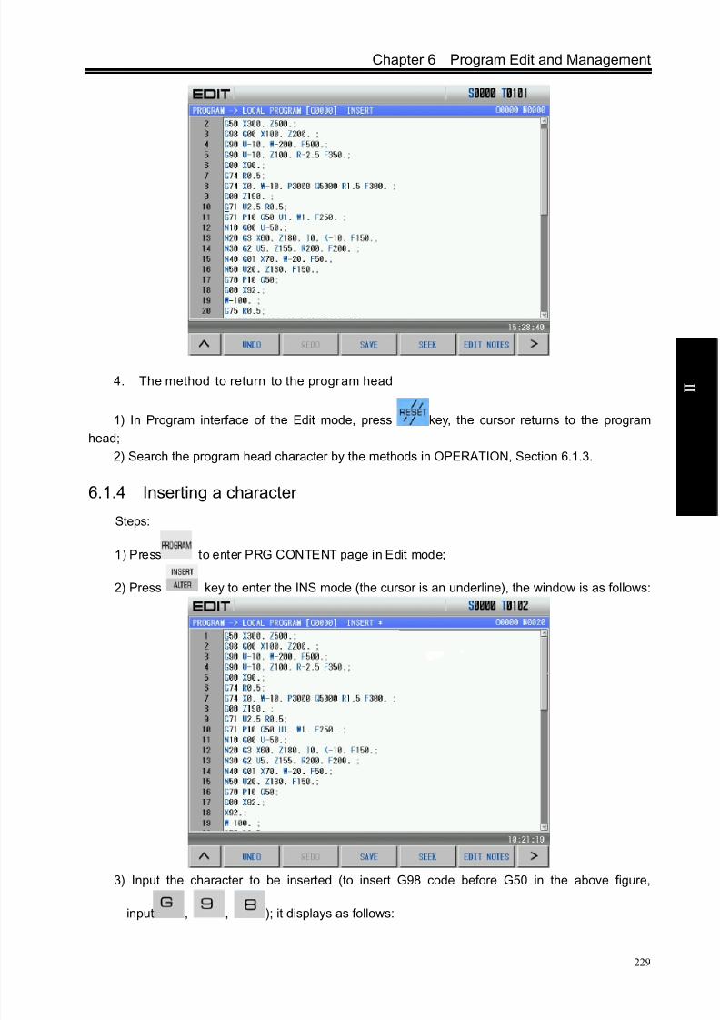
8/17/2019 980TDc CNC Turning Controller User Manual
http://slidepdf.com/reader/full/980tdc-cnc-turning-controller-user-manual 244/461
Chapter 6 Program Edit and Management
229
O p er a t i on
4. The method to return to the program head
1) In Program interface of the Edit mode, press key, the cursor returns to the program
head;
2) Search the program head character by the methods in OPERATION, Section 6.1.3.
6.1.4 Inserting a character
Steps:
1) Press to enter PRG CONTENT page in Edit mode;
2) Press key to enter the INS mode (the cursor is an underline), the window is as follows:
3) Input the character to be inserted (to insert G98 code before G50 in the above figure,
input , , ); it displays as follows:
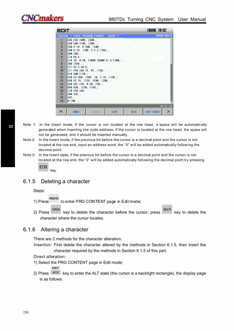
8/17/2019 980TDc CNC Turning Controller User Manual
http://slidepdf.com/reader/full/980tdc-cnc-turning-controller-user-manual 245/461
GSK980TDc Turning CNC System User Manual
230
O p er a t i on
Note 1: In the Insert mode, if the cursor is not located at the row head, a space wil l be automatically
generated when inserting the code address; if the cursor is located at the row head, the space will
not be generated, and it should be inserted manually.
Note 2: In the Insert mode, if the previous bit before the cursor is a decimal point and the cursor is not
located at the row end, input an address word, the “ 0” w ill be added automatically follow ing the
decimal point.
Note 3: In the Insert state, if the previous bit before the cursor is a decimal point and the cursor is not
located at the row end, the “ 0” w ill be added automatically foll owing the decimal point by pressing
key.
6.1.5 Deleting a character
Steps:
1) Press to enter PRG CONTENT page in Edit mode;
2) Press key to delete the character before the cursor; press key to delete the
character where the cursor locates.
6.1.6 Altering a characterThere are 2 methods for the character alteration:
Insertion: First delete the character altered by the methods in Section 6.1.5, then insert the
character required by the methods in Section 6.1.5 of this part.
Direct alteration:
1) Select the PRG CONTENT page in Edit mode;
2) Press key to enter the ALT state (the cursor is a backlight rectangle), the display page
is as follows:

8/17/2019 980TDc CNC Turning Controller User Manual
http://slidepdf.com/reader/full/980tdc-cnc-turning-controller-user-manual 246/461
Chapter 6 Program Edit and Management
231
O p er a t i on
3) Input the modified character(as the above figure, alter X300 to X250, input , ,
), it displays as follows:
Note 1: In ALTER state, the current character where the cursor locates is altered for the input one, and the
cursor moves a byte forward;
Note 2: In ALTER state, if the cursor is located at the “ ;” sign, the input character will substitute this sign,
and the next block will sh ift upward a row.
6.1.7 Deleting a single block
Steps:

8/17/2019 980TDc CNC Turning Controller User Manual
http://slidepdf.com/reader/full/980tdc-cnc-turning-controller-user-manual 247/461
GSK980TDc Turning CNC System User Manual
232
O p er a t i on
1) Press in Edit mode to enter program interface, and press to enter program
content page.
2) Move the cursor to the head of the block to be deleted, then press key.
6.1.8 Copying and pasting a block
Steps:
1) Select Edit mode, and the program content page is displayed;
2) Move the cursor to the required copy block, press , and the current block iscopied;
3) Move the cursor to the required paste position, press , and the copied block ispasted.
6.1.9 Canceling and recovering a program
Steps:1) Select Edit mode, the program content page is shown below:

8/17/2019 980TDc CNC Turning Controller User Manual
http://slidepdf.com/reader/full/980tdc-cnc-turning-controller-user-manual 248/461
Chapter 6 Program Edit and Management
233
O p er a t i on
2) Press to enter the next menu, which is shown below:
3) When the current content is changed(after modification, copy or deletion), ispressed to recover the previous content before the copy;
4) Recover and cancel are matched. Press , to cancel the previousoperation.
6.1.10 Program save
In Edit mode, after the program is edited or modified, although the system automatically saveprograms at regular time, the operator can select the operation to save the current program, whichmethod is shown below:
Method 1:
In the program content page, press to enter the next menu, press to savethe program into the CNC.
Method 2:Switch the current display page and the CNC will automatically save the current program.

8/17/2019 980TDc CNC Turning Controller User Manual
http://slidepdf.com/reader/full/980tdc-cnc-turning-controller-user-manual 249/461
GSK980TDc Turning CNC System User Manual
234
O p er a t i on
Note: “*” in the titl e bar is displayed when the program is not saved.
6.1.11 Macro program edit
Press key repeatedly, it enters MACRO state, as the following window shows:
Then it may input some special characters ([, ], =, >, <, +, *).
e.g. To input character “[”, it may press key repeatedly.
Note: The system cannot execute the program search and the scan in macro program edit state.
6.1.12 Creating and modifying a program annotation
GSK980TDc can add annotation to each line, and its steps are shown below:
1) Select Edit mode, press to enter program interface, press to enter the
program content page;
2) Press and the CNC automatically insert “( )” into the end of line where the cursor
is, and the display page is shown below:

8/17/2019 980TDc CNC Turning Controller User Manual
http://slidepdf.com/reader/full/980tdc-cnc-turning-controller-user-manual 250/461
Chapter 6 Program Edit and Management
235
O p er a t i on
3) Input annotation character into “( ). For example, input “KUAI” character string, and thedisplay page is shown below:
4) The modification of annotation is the same that of program content.
Note : The annotation added to the CNC could only be character. Actuall y, the CNC takes all content in “ ()”
as annotation, so, adding other annotation can be executed by using PC editing, and then be
transmitted to the CNC.
6.2 Deleting Programs
6.2.1 Deleting a program
Steps:
1) Select Edit mode, press to enter program interface, press to enter
program content page;
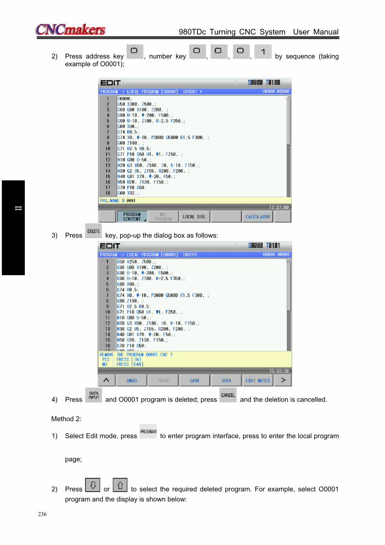
8/17/2019 980TDc CNC Turning Controller User Manual
http://slidepdf.com/reader/full/980tdc-cnc-turning-controller-user-manual 251/461
GSK980TDc Turning CNC System User Manual
236
O p er a t i on
2) Press address key , number key , , , by sequence (takingexample of O0001);
3) Press key, pop-up the dialog box as follows:
4) Press and O0001 program is deleted; press and the deletion is cancelled.
Method 2:
1) Select Edit mode, press to enter program interface, press to enter the local program
page;
2) Press or to select the required deleted program. For example, select O0001
program and the display is shown below:

8/17/2019 980TDc CNC Turning Controller User Manual
http://slidepdf.com/reader/full/980tdc-cnc-turning-controller-user-manual 252/461
Chapter 6 Program Edit and Management
237
O p er a t i on
3) Press key, pop-up the dialog box as follows:
4) Press and O0001 program is deleted; press and the deletion is cancelled.
6.2.2 Deleting all programs
Steps:
1) Refer to Section 6.2.1, Method 2 to enter the local program page;
2) Press to enter the next menu and the display is shown below:
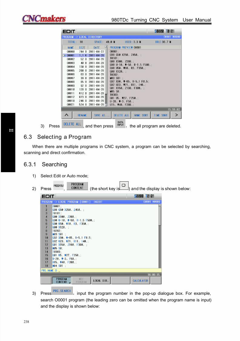
8/17/2019 980TDc CNC Turning Controller User Manual
http://slidepdf.com/reader/full/980tdc-cnc-turning-controller-user-manual 253/461
GSK980TDc Turning CNC System User Manual
238
O p er a t i on
3) Press , and then press ,the all program are deleted.
6.3 Selecting a Program
When there are multiple programs in CNC system, a program can be selected by searching,
scanning and direct confirmation.
6.3.1 Searching
1) Select Edit or Auto mode;
2) Press , (the short key is ) and the display is shown below:
3) Press ,input the program number in the pop-up dialogue box. For example,
search O0001 program (the leading zero can be omitted when the program name is input)
and the display is shown below:

8/17/2019 980TDc CNC Turning Controller User Manual
http://slidepdf.com/reader/full/980tdc-cnc-turning-controller-user-manual 254/461
Chapter 6 Program Edit and Management
239
O p er a t i on
4) Press (or , , ), the searched program will be displayed. If the program
does not exist, the CNC prompts “File does not exist”.
Note: In Edit mode, press or to search programs. When there is no programs, the CNC
automatically creates programs; press or to execute the search, and the CNC prompts
“ The file does not exist” when there is not the program.
6.3.2 Scanning
1) Select Edit or Auto mode;
2) Press to enter the program display page;
3) Press ;
4) Press or to display the next or previous program;
5) Repeat step 3 and 4 to display the saved programs one by one.
6.3.3 Direct confirmation
1) Select Edit or Auto mode (must be in non-run state);
2) Press to enter the program interface. When the system is not in “Local Directory” ,
is pressed, which displays is shown below:
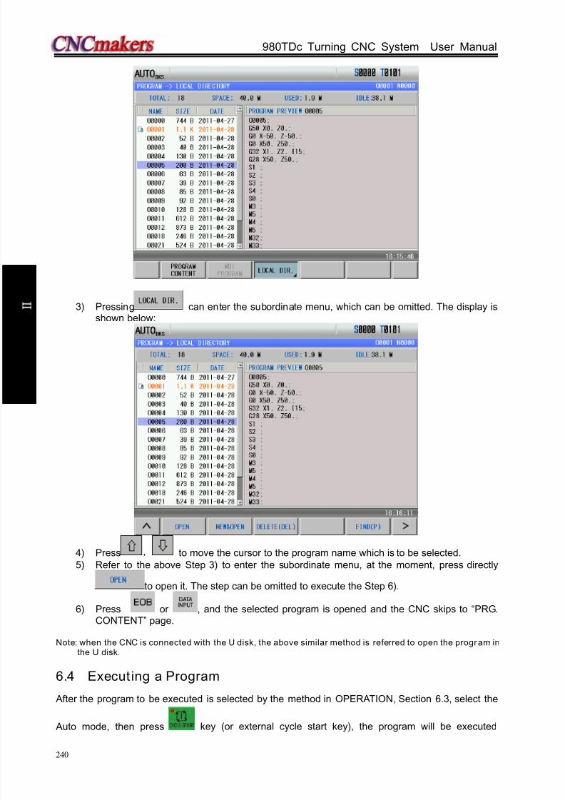
8/17/2019 980TDc CNC Turning Controller User Manual
http://slidepdf.com/reader/full/980tdc-cnc-turning-controller-user-manual 255/461
GSK980TDc Turning CNC System User Manual
240
O p er a t i on
3) Pressing can enter the subordinate menu, which can be omitted. The display isshown below:
4) Press , to move the cursor to the program name which is to be selected.
5) Refer to the above Step 3) to enter the subordinate menu, at the moment, press directly
to open it. The step can be omitted to execute the Step 6).
6) Press or , and the selected program is opened and the CNC skips to “PRG.CONTENT” page.
Note: when the CNC is connected with the U disk, the above similar method is referred to open the program inthe U disk.
6.4 Execut ing a Program
After the program to be executed is selected by the method in OPERATION, Section 6.3, select the
Auto mode, then press key (or external cycle start key), the program will be executed

8/17/2019 980TDc CNC Turning Controller User Manual
http://slidepdf.com/reader/full/980tdc-cnc-turning-controller-user-manual 256/461
Chapter 6 Program Edit and Management
241
O p er a t i on
automatically.
6.5 Renaming a Program
Methods of renaming a program is divided into two:Method 1:
1) Select Edit mode, press to enter the program interface, and in necessity press
to enter PRG CONTENT page (must be in Insert, Alter state):
2) Press to input a new program name;
3) Press .
Method 2:
1) Select Edit mode, press to enter the program interface, and in necessity press
to enter the local directory page:

8/17/2019 980TDc CNC Turning Controller User Manual
http://slidepdf.com/reader/full/980tdc-cnc-turning-controller-user-manual 257/461
GSK980TDc Turning CNC System User Manual
242
O p er a t i on
2) Press again to enter the subordinate menu, and press to open it:
3) Move the cursor to the program which is to be modified, press and input a new
program name in the pop-up diaglog box, and at last press .
Note: the method 1 is only used to the current program, and the method 2 is used to any programs.
6.6 Copying a Program
Methods of copying a program is divided into two:Method 1:
1) Select Edit mode, press to enter the program interface, and in necessity press
to enter PRG CONTENT page (must be in Insert, Alter state):
2) Press to input a new program name;
3) Press .
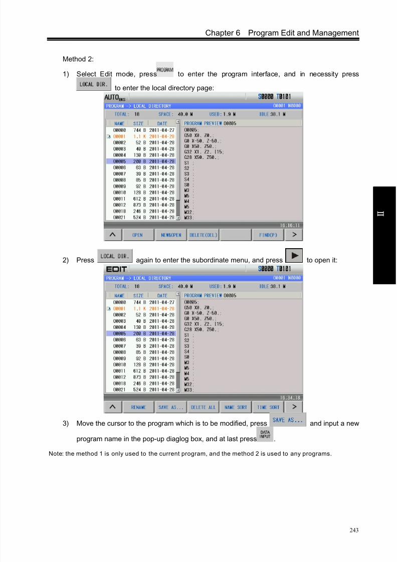
8/17/2019 980TDc CNC Turning Controller User Manual
http://slidepdf.com/reader/full/980tdc-cnc-turning-controller-user-manual 258/461
Chapter 6 Program Edit and Management
243
O p er a t i on
Method 2:
1) Select Edit mode, press to enter the program interface, and in necessity press
to enter the local directory page:
2) Press again to enter the subordinate menu, and press to open it:
3) Move the cursor to the program which is to be modified, press and input a new
program name in the pop-up diaglog box, and at last press .
Note: the method 1 is only used to the current program, and the method 2 is used to any programs.
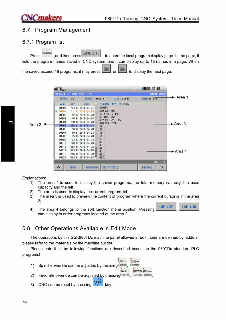
8/17/2019 980TDc CNC Turning Controller User Manual
http://slidepdf.com/reader/full/980tdc-cnc-turning-controller-user-manual 259/461
GSK980TDc Turning CNC System User Manual
244
O p er a t i on
6.7 Program Management
6.7.1 Program list
Press ,and then press to enter the local program display page. In the page, itlists the program names saved in CNC system, and it can display up to 18 names in a page. When
the saved exceed 18 programs, it may press or to display the next page.
Explanations:1) The area 1 is used to display the saved programs, the total memory capacity, the used
capacity and the left;2) The area is used to display the current program list;3) The area 3 is used to preview the content of program where the current cursor is in the area
2;
4) The area 4 belongs to the soft function menu position. Pressing ,can display in order programs located at the area 2.
6.8 Other Operations Available in Edit Mode
The operations by this GSK980TDc machine panel allowed in Edit mode are defined by ladders,
please refer to the materials by the machine builder.
Please note that the following functions are described based on the 980TDc standard PLC
programs!
1) Spindle override can be adjusted by pressing , ;
2) Feedrate override can be adjusted by pressing , ;
3) CNC can be reset by pressing key;
Area 1
Area 4
Area 2 Area 3
8/17/2019 980TDc CNC Turning Controller User Manual
http://slidepdf.com/reader/full/980tdc-cnc-turning-controller-user-manual 260/461
Chapter 6 Program Edit and Management
245
O p er a t i on
4) The operation mode is switched by pressing any of the keys among , , ,
, or ;5) The data transmission6) Refer to II OPERATION, Chapter 12
7) Cooling controlRefer to II Operation, Section 3.2.3
8) Lubricating controlRefer to II Operation, Section 3.2.4
9) Chuck control
Refer to II Operation, Section 3.2.510) Tailstock control
11) Refer to II Operation, Section 3.2.6
12) Hydraulic controlRefer to II Operation, Section 3.2.7
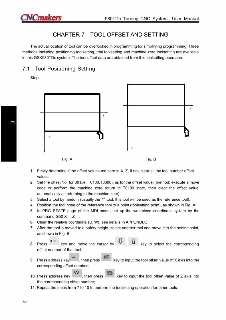
8/17/2019 980TDc CNC Turning Controller User Manual
http://slidepdf.com/reader/full/980tdc-cnc-turning-controller-user-manual 261/461
GSK980TDc Turning CNC System User Manual
246
O p er a t i on
CHAPTER 7 TOOL OFFSET AND SETTING
The actual location of tool can be overlooked in programming for simplifying programming. Three
methods including positioning toolsetting, trial toolsetting and machine zero toolsetting are available
in this GSK980TDc system. The tool offset data are obtained from this toolsetting operation.
7.1 Tool Positioning Setting
Steps:
x
Z
X
Z
Fig. A Fig. B
1. Firstly determine if the offset values are zero in X, Z, if not, clear all the tool number offset
values;
2. Set the offset No. for 00 (i.e. T0100,T0300), as for the offset value: (method: execute a move
code or perform the machine zero return in T0100 state, then clear the offset value
automatically as returning to the machine zero);
3. Select a tool by random (usually the 1st tool, this tool will be used as the reference tool);
4. Position the tool nose of the reference tool to a point (toolsetting point), as shown in Fig. A;
5. In PRG STATE page of the MDI mode, set up the workpiece coordinate system by the
command G50 X__ Z__;
6. Clear the relative coordinate (U, W), see details in APPENDIX;7. After the tool is moved to a safety height, select another tool and move it to the setting point,
as shown in Fig. B;
8. Press key and move the cursor by , key to select the corresponding
offset number of that tool;
9. Press address key , then press key to input the tool offset value of X axis into the
corresponding offset number;
10. Press address key , then press key to input the tool offset value of Z axis into
the corresponding offset number;
11. Repeat the steps from 7 to 10 to perform the toolsetting operation for other tools.
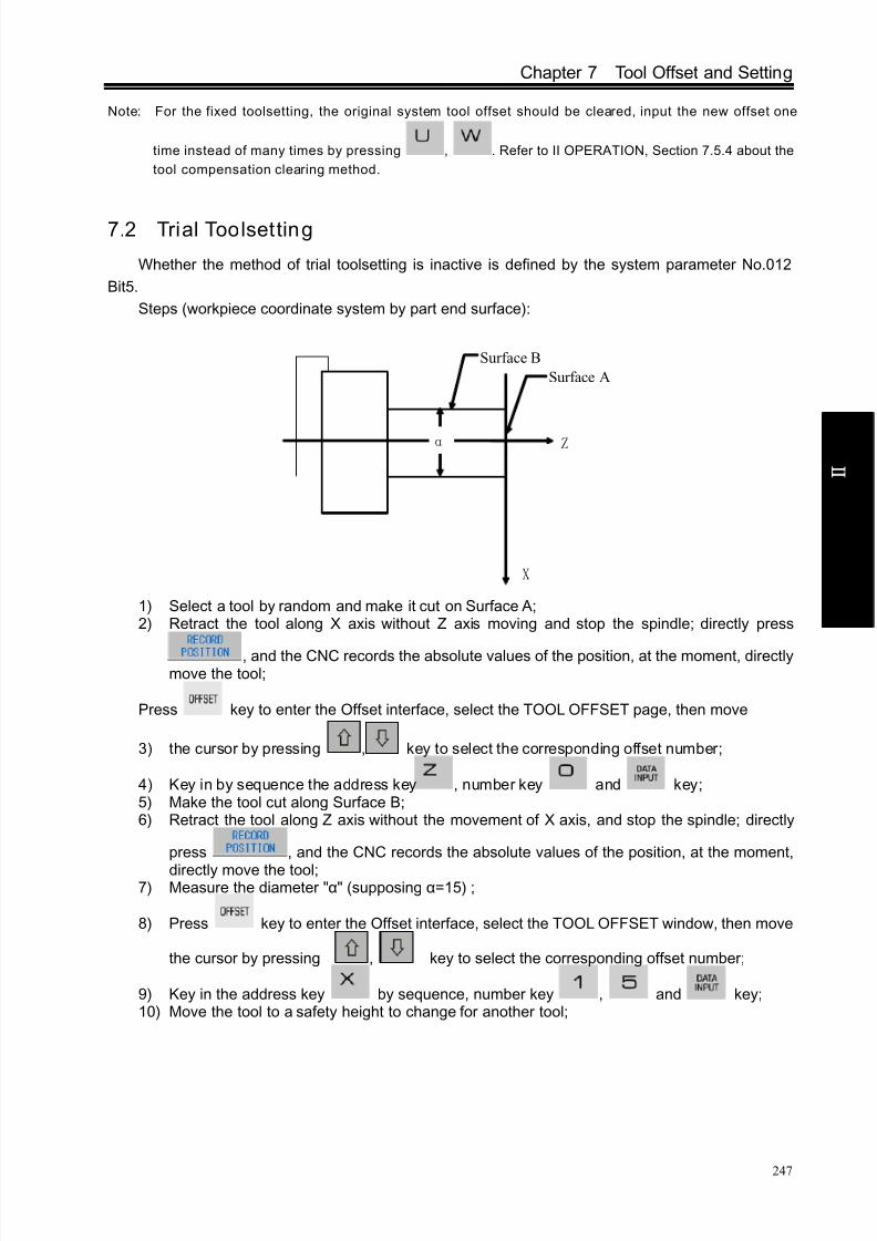
8/17/2019 980TDc CNC Turning Controller User Manual
http://slidepdf.com/reader/full/980tdc-cnc-turning-controller-user-manual 262/461
Chapter 7 Tool Offset and Setting
247
O p er a t i on
Note: For the fixed toolsetting, the original system tool offset should be cleared, input the new offset one
time instead of many times by pressing , . Refer to II OPERATION, Section 7.5.4 about the
tool compensation clearing method.
7.2 Trial Toolsetting
Whether the method of trial toolsetting is inactive is defined by the system parameter No.012
Bit5.
Steps (workpiece coordinate system by part end surface):
Z
X
α
Surface A
Surface B
1) Select a tool by random and make it cut on Surface A;2) Retract the tool along X axis without Z axis moving and stop the spindle; directly press
, and the CNC records the absolute values of the position, at the moment, directlymove the tool;
Press key to enter the Offset interface, select the TOOL OFFSET page, then move
3) the cursor by pressing , key to select the corresponding offset number;
4) Key in by sequence the address key , number key and key;5) Make the tool cut along Surface B;6) Retract the tool along Z axis without the movement of X axis, and stop the spindle; directly
press , and the CNC records the absolute values of the position, at the moment,
directly move the tool;7) Measure the diameter "α" (supposing α=15) ;
8) Press key to enter the Offset interface, select the TOOL OFFSET window, then move
the cursor by pressing , key to select the corresponding offset number;
9) Key in the address key by sequence, number key , and key;10) Move the tool to a safety height to change for another tool;

8/17/2019 980TDc CNC Turning Controller User Manual
http://slidepdf.com/reader/full/980tdc-cnc-turning-controller-user-manual 263/461
GSK980TDc Turning CNC System User Manual
248
O p er a t i on
Z
X
αˊ
表面 A1
表面 B1
βˊ
11) Make the tool to cut on Surface A1;12) Retract the tool along X axis without Z axis moving and stop the spindle;
13) Measure the distance "βˊ" between the Surface A1 and the workpiece coordinateorigin(supposing βˊ=1) ;
14) Press key to enter the Offset interface, select the TOOL OFFSET page, then move the
cursor by pressing , to select the corresponding offset number;
15) Key in by sequence the address key , sign key , number key , andkey;
16) Make the tool to cut on Surface B1;17) Retract the tool along Z axis without the movement of X axis, and stop the spindle;18) Measure the distance "α’ " (supposing α’=10);
19) Press key to enter the Offset interface, select the TOOL OFFSET window, then move
the cursor by pressing , to select the corresponding offset number;
20) Press orderly the address key , number key , and key;21) Repeat the execution from Step 10 to Step 20 to perform the toolsetting operation for other
tools.Note: The offset value may be large by this toolsetting method, so the tool compensation should be done by
the coordinate offset by the CNC system. (set the BIT4 of the CNC parameter No.003 to 1). Moreover,
the tool lengths compensation should be performed by using the T code in the 1st block, or the 1st
move block should contain the T code for the tool length compensation.
7.3 Toolsett ing by Machine Zero Return
There is no reference tool in this toolsetting methods, when the tool is worn or to be adjusted, it
only needs to be set again, and a machine zero return should be done before the toolsetting. The
machining could be continued by performing a machine zero return at power on after power-off, which
is very convenient for the operation.
Steps (workpiece coordinate system by part end surface):
Surface A1
Surface B1

8/17/2019 980TDc CNC Turning Controller User Manual
http://slidepdf.com/reader/full/980tdc-cnc-turning-controller-user-manual 264/461
Chapter 7 Tool Offset and Setting
249
O p er a t i on
Z
X
α
表面 A
表面 B
1) Press key to enter Machine Zero mode, move axes to machine zero;2) Select a tool by random and set the offset number of the tool to 00 (e.g. T0100, T0300) ;3) Make the tool to cut on Surface A;4) Retract the tool along X axis without the movement of Z axis, and stop the spindle; directly
press , and the CNC records the absolute values of the position, at the moment,directly move the tool;
5) Press key to enter the Offset interface, select the TOOL OFFSET window, then move
the cursor by pressing , key to select the corresponding offset number;
6) Key in by sequence the address key , number key and key to set theoffset value of Z axis;
7) Make the tool cut along Surface B;8) Retract the tool along Z axis without the movement of X axis, and stop the spindle;9) Measure the distance "α"(supposing α=15);
10) Press key to enter the Offset interface, select the TOOL OFFSET window, then move
the cursor by pressing , to select the corresponding offset number;
11) Key in by sequence the address key , number key , and key to setthe offset value of X axis;
12) Move the tool to a safety height for tool change;13) Change for another tool, and set the tool offset number to 00 (i.e. T0100, T0300);
Surface B
Surface A
Z
X
α1
表面 A1
表面 B1
β1
Surface B1
Surface A1

8/17/2019 980TDc CNC Turning Controller User Manual
http://slidepdf.com/reader/full/980tdc-cnc-turning-controller-user-manual 265/461
GSK980TDc Turning CNC System User Manual
250
O p er a t i on
14) Make the tool to cut on Surface A1;15) Retract the tool along X axis without Z axis moving and stop the spindle; measure the
distance "β1" between the Surface A1 and the workpiece coordinate system origin(supposing β1=1) ;
16) Press key to enter the Offset interface, select the TOOL OFFSET window, then move
the cursor by pressing , to select the corresponding offset number;
17) Key in by sequence the address key , sign key , number key , andkey to set Z offset value;
18) Make the tool to cut on Surface B1;19) Retract the tool along Z axis without the movement of X axis, and stop the spindle;20) Measure the distance "α1" (supposing α1=10);
21) Press key to enter the Offset interface, select the TOOL OFFSET window, then move
the cursor by pressing , key to select the corresponding offset number;
22) Key in by sequence the address key , number key , and key to setX offset value;
23) Move the tool to a safety position;24) Repeat the execution from Step 12 to Step 23 to perform the toolsetting operation for other
tools.
Note 1: Machine zero switch must be fixed for the toolsetting operation by machine zero return.
Note 2: The workpiece coordinate system setting can’t be done by G50 code after toolsetting by machine
zero return.
Note 3: The tool compensation should be done by coordinate offset by the CNC system (the system
parameter No.003 Bit4 is set to 1), further more, the tool lengths compensation should be performed
by using the T code in the 1st block, or the 1st move block should contain the T code for the toollength compensation.
Note 4: The corresponding parameters should be set as follows:
Bit7=0 of the system parameter No.004;
Bit5=1 of the system parameter No.012;
Bit7=1 of the system parameter No.012.
Note 5: The setting values of the system parameter No.047 should be close to the absolute coord inate
values of machine zero in workp iece coordinate system XOZ, as is shown in the following figu re:
As shown below:
Example: After machine zero returning, when the absolute coordinate of the tool in workpiece
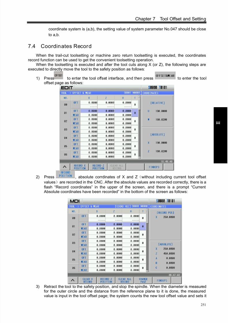
8/17/2019 980TDc CNC Turning Controller User Manual
http://slidepdf.com/reader/full/980tdc-cnc-turning-controller-user-manual 266/461
Chapter 7 Tool Offset and Setting
251
O p er a t i on
coordinate system is (a,b), the setting value of system parameter No.047 should be close
to a,b.
7.4 Coordinates Record
When the trail-cut toolsetting or machine zero return toolsetting is executed, the coordinatesrecord function can be used to get the convenient toolsetting operation.When the toolsetting is executed and after the tool cuts along X (or Z), the following steps are
executed to directly move the tool to the safety position as follows:
1) Press to enter the tool offset interface, and then press to enter the tooloffset page as follows:
2) Press , absolute corrdinates of X and Z(without including current tool offset
values)are recorded in the CNC. After the absolute values are recorded correctly, there is a
flash “Record coordinates” in the upper of the screen, and there is a prompt “Current Absolute coordinates have been recorded” in the bottom of the screen as follows:
3) Retract the tool to the safety position, and stop the spindle. When the diameter is measuredfor the outer circle and the distance from the reference plane to it is done, the measuredvalue is input in the tool offset page; the system counts the new tool offset value and sets it

8/17/2019 980TDc CNC Turning Controller User Manual
http://slidepdf.com/reader/full/980tdc-cnc-turning-controller-user-manual 267/461
GSK980TDc Turning CNC System User Manual
252
O p er a t i on
to the selected tool offset number according to the input value and the previous recordedabsolute coordinates.
Use the following methods to clear the recorded coordinates when the above methods are usedto execute the toolsetting:
1) In the tool offset page, after the absolute coordinates are input in some tool offset(for
example: Z0 is input in the No.01 tool offset number) and then the axis moves, the recordedcoordinates are cleared;
2) Press + simultaneously, and the recorded coordinates are cleared;
3) Press in the tool offset page and the recorded coordinates are cleared.
7.5 Setting and Altering the Offset Value
Refer to Section 1.3.3 about methods of entering the offset setting page.
7.5.1 Offset setting
1) Press key to enter the offset setting page, select the desired window by pressing the
, ;
2) Move the cursor to the location of the tool offset, wear number to be input.
Scanning: Press , to move the cursor in sequent
Searching: use the following press keys to directly move the cursor to the input position:
Press + offset number + or and input the offset number in
the pop-up dialogue box, press and the cursor directly positions the target
offset number.
3) After pressing the address key or , the numerical number may be keyed in
(decimal point allowed);
4) Press and the CNC calculates the offset value automatically and displays the result
in the window.
7.5.2 Offset alteration
1) Refer to OPERATION, Section 7.5.1, and move the cursor to the location of the offset
number that is to be altered;
2) If the offset value of X axis is to be altered, key in U; as for that of Z axis, key in W;;
3) Then key in the incremental value;
4) Press to add the current offset value to the value keyed in, the operation result will bedisplayed as a new offset value.
Example: The set X axis offset value is 5.678

8/17/2019 980TDc CNC Turning Controller User Manual
http://slidepdf.com/reader/full/980tdc-cnc-turning-controller-user-manual 268/461
Chapter 7 Tool Offset and Setting
253
O p er a t i on
The increment keyed in is U 1.5
Then the new offset value is 7.178 (=5.678+1.5)
7.5.3 Offset alteration in communication mode
For the alteration and setting of the offset value in the communication, please see Chapter 12 ofthis part for its operations.
Note 1: While changing the offset value, the new offset value takes effect after the T code is executed.
Note 2: If the actual workpiece dimensions doesn’t confo rms to that of the part drawing, subtract the error
from the orig inal offset value for the oversize workpiece, add the error to the original offset value for
the undersize workpiece.
Example: The external diameter of the workpiece to be machined is Ф55.382, and the No.01 offset
value is applied in the machining. Before machining, the values in No.01 are shown as
follows table:
No. X Z T R
00 0 0 0 0
01 16.380 -24.562 0 0
In machining, the actual external diameter measured of workpiece is Ф55.561, so the offset
value of No.01 can be altered as follows table:
No. X Z T R
00 0 0 0 0
01 16.201 -24.562 0 0
Note: To backup and restore the too l offset values, the relevant operations may be performed on PC via
communication.
7.5.4 Clearing the offset values
1) Move the cursor to the offset number to be cleared;
2) When the offset value of X axis is to be cleared, is pressed, then is done, the
offset will be cleared. Other axis clearing is done like that;Note: The offset clearing in the tool offset page doesn’t mean that the system in under the state with no
offsetting, if t he system is needed to be in thi s state, the offsetting i s required to be executed, which is
shown as follows:
Execute a positioning command in T0100 state or perform a machine zero return. After the offsetting is
finished, the “” in “T” shown at the right bottom of the screen will no t be backlighted.
7.5.5 Setting and altering the tool wear
To prevent the mistaken operation of the setting and alteration of the offset value (decimal point
missed, mislocated etc.), which may cause the tool collision by oversize offset value, for the visual
judgement for the tool wear by the operator, the TOOL WEAR window is set in this GSK980TDc
system. When the offset value is needed to be altered due to the inaccurate dimensions by the tool
wear, it may set or alter the wear value. The wear input range is defined by the data parameter
No.140, and they are saved even at power down.The setting and alteration methods for the tool wear are approximately identical to that of the tool
offset, and the wear value is input by U(X axis), W(Z axis), V(Y axis).
16.380-
55.561-55.382)
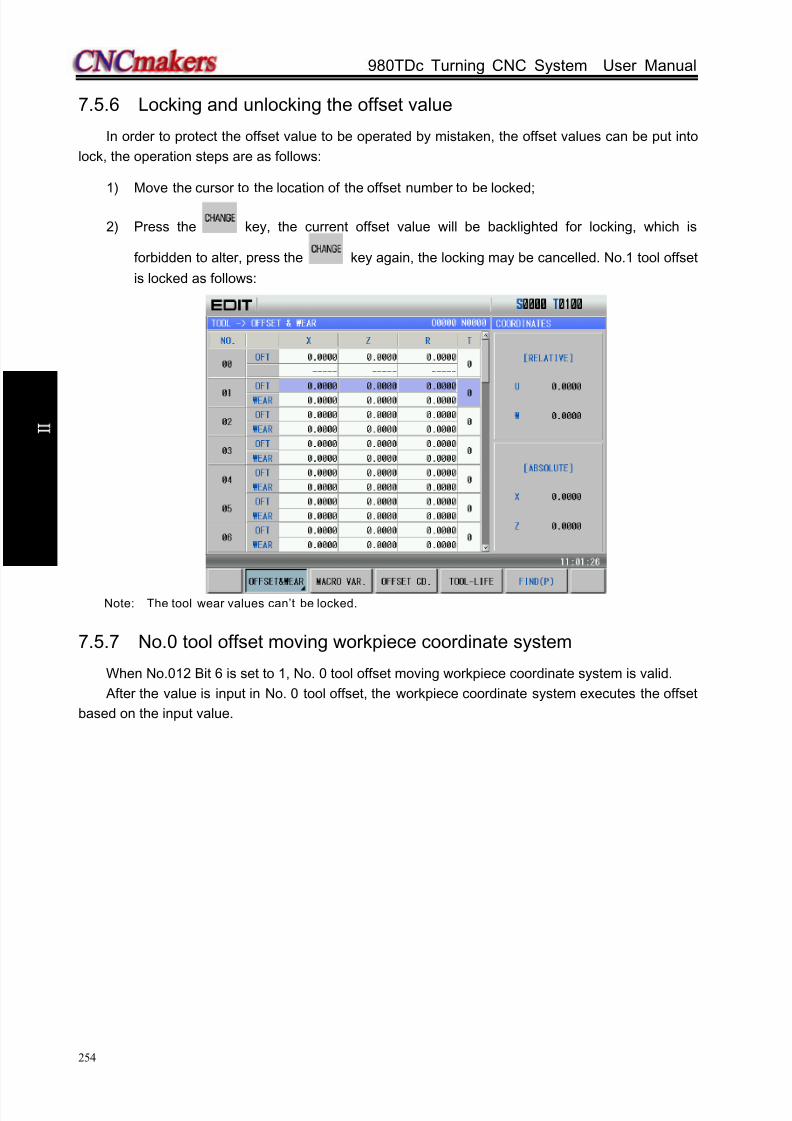
8/17/2019 980TDc CNC Turning Controller User Manual
http://slidepdf.com/reader/full/980tdc-cnc-turning-controller-user-manual 269/461
GSK980TDc Turning CNC System User Manual
254
O p er a t i on
7.5.6 Locking and unlocking the offset value
In order to protect the offset value to be operated by mistaken, the offset values can be put into
lock, the operation steps are as follows:
1) Move the cursor to the location of the offset number to be locked;
2) Press the key, the current offset value will be backlighted for locking, which is
forbidden to alter, press the key again, the locking may be cancelled. No.1 tool offset
is locked as follows:
Note: The tool wear values can’t be locked.
7.5.7 No.0 tool offset moving workpiece coordinate system
When No.012 Bit 6 is set to 1, No. 0 tool offset moving workpiece coordinate system is valid.
After the value is input in No. 0 tool offset, the workpiece coordinate system executes the offset
based on the input value.
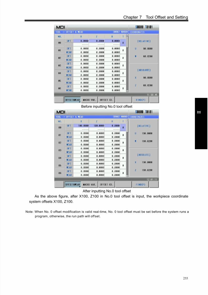
8/17/2019 980TDc CNC Turning Controller User Manual
http://slidepdf.com/reader/full/980tdc-cnc-turning-controller-user-manual 270/461
Chapter 7 Tool Offset and Setting
255
O p er a t i on
Before inputting No.0 tool offset
After inputting No.0 tool offset
As the above figure, after X100, Z100 in No.0 tool offset is input, the workpiece coordinate
system offsets X100, Z100.
Note: When No. 0 offset modification is valid real-time, No. 0 tool offset must be set before the system runs a
program, otherwise, the run path will off set.

8/17/2019 980TDc CNC Turning Controller User Manual
http://slidepdf.com/reader/full/980tdc-cnc-turning-controller-user-manual 271/461
GSK980TDc Turning CNC System User Manual
256
O p er a t i on
CHAPTER 8 AUTO OPERATION
8.1 Automatic Run
8.1.1 Selection of a program running
Refer to Section 6.3.
8.1.2 Start of automatic run
1. Press to select the Auto mode;
2. Press to start the program, and the program automatically runs.Note: Since the program execution begins from the block where the cursor locates, before pressing the
, make a check whether the cursor is located at the block to be executed.
8.1.3 Stop of automatic run
Stop by code (M00)
1. M00
After the block containing M00 is executed, the auto run is stopped. So the modal function and
state are all reserved. Press the or the external run key, the program execution continues.
2. M01
Press and the optional stop indicator is ON and the function is valid. After the block with
M01 is executed, the system stops the automatic run, the modal function and the state are saved.
Press or the external run key, and the program continuously runs.
Stop by a relevant key
1. In Auto run, by pressing or external pause key, the machine keeps the following state:
(1) The machine feed slows down to stop;
(2) The modal function and state are reserved;
Note
The key functions of GSK980TDc machine panel are defined by PLC program
(ladders), please refer to the materials by the machine builder for their
significance.
Please note that the following description for the keys function in this chapter
is based on GSK980TDc standard PLC program!

8/17/2019 980TDc CNC Turning Controller User Manual
http://slidepdf.com/reader/full/980tdc-cnc-turning-controller-user-manual 272/461
Chapter 8 AUTO Operation
257
O p er a t i on
(3) The program execution continues after pressing the key.
2. Stop by Reset key
(1) All axes movement is stopped.
(2) M, S function output is inactive (the automatic cut-off of signals such as spindle CCW/CW,
lubricating, cooling by pressing key can be set by the parameters)
(3) Modal function and state is held on after the auto run.
3. Stop by Emergency stop button
If the external emergency button (external emergency signal active) is pressed under the
dangerous or emergent situation during the machine running, the CNC system enters into emergency
state, and the machine moving is stopped immediately, all the output (such as spindle rotation,
cooling) are all cut off. If the Emergency button is released, the alarm is cancelled and CNC system
enters into reset mode.4. Switching operation mode
When Auto mode is switched to the Machine zero, MPG/Step, Manual, Program zero mode, the
current block “dwells” immediately; when the Auto mode is switched to the Edit, MDI mode in Auto
mode, the “dwell” is not displayed till the current block is executed.
Note 1: Ensure that the fault has been resolved before cancelling the emergency alarm.
Note 2: The electric shock to the device may be decreased by pressing the Emergency button before power
on and off.
Note 3: The Machine zero return operation should be performed again after the emergency alarm is
cancelled to ensure the correctness of the position coordinates (but this operation is forbidden if
there is no machine zero in the machine).Note 4: Only the BIT3 (MESP) of the bit parameter No.172 is set to 0, could the external emergency stop be
active.
8.1.4 Automatic run from an arbitrary block
Press key to enter the Edit mode, press key to enter the program content page;
1) Move the cursor to the block to be executed (for example, move the cursor to the 3rd row head ifit executes from the 3
rd row);

8/17/2019 980TDc CNC Turning Controller User Manual
http://slidepdf.com/reader/full/980tdc-cnc-turning-controller-user-manual 273/461
GSK980TDc Turning CNC System User Manual
258
O p er a t i on
2) If the mode (G, M, T, F code) of the current block where the cursor locates is defaulted andinconsistent with the running mode of this block, the corresponding modal function should beexecuted to continue next step.
3) Press key to enter the Auto mode, then press key to start the execution.
8.1.5 Adjustment of the feedrate, rapid rate
In Auto mode, the running speed can be changed by adjusting the feedrate override, rapid
override. It doesn’t need to change the settings of the program and parameter.
Adjustment of the feedrate override
Press , , 16-level real time feedrate can be obtained.
Note 1: The actual feedrate value is specified by F in feedrate override adjustment;
Note 2: Actual feedrate= value specifi ed by F× feedrate override
Adjustment of rapid over ride
It can realize the F0, 25%, 50%, 100% 4-level real time rapid override adjustment by
pressing , , , .
Note 1: The rapid traverse speeds of X, Z axis are set by the system parameter No.022, No.023
X axis actual rapid traverse rate = value set by parameter No.022X×rapid override
Z axis actual rapid t raverse rate = value set by parameter No.022Z×rapid override
Note 2: When the rapid override is F0, the min. rapid traverse rate is set by bit parameter No.032.
8.1.6 Spindle speed adjustment
While the spindle speed is controlled by the analog voltage output in Auto mode, it can be
adjusted by spindle override.
Press , to adjust the spindle override for the spindle speed, it can realize 8-level
real-time override adjustment between 50%~120%.

8/17/2019 980TDc CNC Turning Controller User Manual
http://slidepdf.com/reader/full/980tdc-cnc-turning-controller-user-manual 274/461
Chapter 8 AUTO Operation
259
O p er a t i on
Note : The actual output analog voltage = analog voltage by parameter × spindle override.
8.2 Running State
8.2.1 Single block execution
When a program is executed firstly, the system selects the single block run mode to avoid the
program error to cause the unexpected.
Press to select the single block run function in Auto mode; in single block mode, after the
current block is executed, the CNC stops run; press to execute the next block. Such repetition
is executed till the program is done.
Note 1: The single block stops at the mid point of G28 code.Note 2: For the single block state in the execution of canned cycle codes G90, G92, G94, G70~G76, refer to
the 1st part PROGRAMMING.
Note 3: While the subprogram calling (M98 ), or subprogram calling return (M99)is being executed, the
single block is inactive. But it is active except for N, O, P addresses in the block that contains M98 or
M99 code.
8.2.2 Dry run
Before the program is to be executed automatically, in order to avoid the programming errors, it
may select the Dry run mode to check the program.
In Auto mode, press to enter the dry run state; in Dry run state, the machine feed and
miscellaneous functions are both active (as machine lock, MST lock are both OFF), that means the
dry run switch has nothing to do with the machine feeding, MST functions, so the feedrate by program
is inactive and the CNC system runs at the speed described in the following table:
Program command
Rapid traverse Cutting feed
Rapid traverse switch ON Rapid traverse Max. manual feedrate
Rapid traverse switch OFF
Manual feedrate or rapid
traverse(see note) Manual feedrate
Note 1: The rate by manual feedrate or rapid rate is set by the BIT6 of the CNC system parameter No.004.
Note 2: The shift of rapid switch in Dry run mode doesn’t affect the rate of the current block being executed,
but that of the next block.
Note 3: The switch operation of Dry run is inactive if the ladder of this GSK980TDc is defined to be in auto
runn ing s tate (Auto, MDI mode).
8.2.3 Machine lock
In Auto mode, press to enter the machine lock; the machine lock and MST lock are usuallyused together to check the program. While the machine is in the lock run state:
1. The machine carriage doesn’t move, the “MACHINE” in the INTEGRATED POS window of the

8/17/2019 980TDc CNC Turning Controller User Manual
http://slidepdf.com/reader/full/980tdc-cnc-turning-controller-user-manual 275/461
GSK980TDc Turning CNC System User Manual
260
O p er a t i on
Position interface doesn’t vary too. The RELATIVE POS and ABSOLUTE POS, DIST TO GO
are refreshed continuously, which is the same as that the machine lock switch is OFF.
2. M, S, T commands can be executed normally.
8.2.4 MST lock
In Auto mode, press to enter the miscellaneous function lock state; The machine carriage
moves without the M, S, T code being executed. The machine lock and MST lock are usually used
together to check the program.
Note: When the MST lock is active, it takes no effect to the execution of M00, M29, M30, M98, M99.
8.2.5 Block skip
When a block in program is not needed to be executed and not to be deleted, this block skipfunction can be used. When the block is headed with “/ ” sign and Block skip indicator lights up (panel
key active or external skip input active), this block is skipped without execution in Auto mode. In Auto
mode, press to enter the state that the program skip is valid.
Note: While the block skip switch is off, the blocks headed with “ /” signs are executed normally in Auto
mode.
8.3 MPG Trial-cutThe user can use MPG trial-cut function after editing part programs, check the run path of
program. In MPG trial-cut function, rotating MPG controls the execution speed of program, which can
easily check the program error conveniently.
8.3.1 Switching MPG trial-cut mode
Press to enter the MPG trial-cut mode after a machinig program is selected as follows:

8/17/2019 980TDc CNC Turning Controller User Manual
http://slidepdf.com/reader/full/980tdc-cnc-turning-controller-user-manual 276/461
Chapter 8 AUTO Operation
261
O p er a t i on
At the moment, press and the display is shown below:
At the moment, rotating MPG makes the program start running. When the execution speed of
program is proportional to MPG speed, execution speed of program fastens as soon as the MPGrapidly rotates; the execution speed slows down as soon as the MPG slowly rotates. Movement
amount of one pulse can be adjusted by rapid override.
When the system is in the MPG trial-cut mode, it returns to Auto mode after is pressed. All
operations in MPG trial-cut mode are the same those of Auto mode.
8.3.2 Command speed in MPG trial-cut mode
1) Cutting feedrate
Cutting command speed in MPG trial-cut mode is determined by No. 241 and rapid override. The
command speed during actually rotating MPG is executed by the following:
[Command speed]×[MPG pulse amount per 1 second]×λ×([the parameter setting value] /100) ×

8/17/2019 980TDc CNC Turning Controller User Manual
http://slidepdf.com/reader/full/980tdc-cnc-turning-controller-user-manual 277/461
GSK980TDc Turning CNC System User Manual
262
O p er a t i on
(8/1000) (mm/min or inch/min)。
λ value is determined by the current rapid override, and their relationship is:
Rapid override λ value Rapid override λ value
F0 1 25% 10
50% 100 100% 100
Rapid traverse speed is clamped at 100% speed when it exceeds 100%, i.e.:
[MPG pulse amount per 1 second]×λ×([No.241setting value]/100)×(8/1000)≤1
2) Rapid traverse speed
Rapid traverse speed is clamped at the speed set by No.240, i.e.:
[Rapid traverse speed]=[rapid traverse speed of each axis]×([No.240 setting value]/100)× [MPG
pulse amount per 1 second]×λ×([No.241 setting value]/100)×(8/1000)
At the moment, when the speed by rapidly rotating MPG exceeds the clamped, the rapid traverse
speed is clamped at the setting value by parameter, i.e.:
[MPG pulse amount per 1 second]×λ×([No.241 setting value]/100)×(8/1000) ≤1
8.3.3 Notes in MPG trial-cut mode
Pay more attention to the followings when the system is in MPG trial-cut mode:
1) Press in Auto mode and the CNC does not switch to MPG trial-cut mode; when the
CNC is in MPG trial-cut mode, it escapes the MPG trial-cut mode from the next block by
pressing the mode switch key;
2) When the system executes the MPG trial-cut control, the single block signal and the feed
hold signal are valid. When the single block or feed hold stops, the program execution state
is recovered to the MPG trial-cut control after the cycle start key is pressed.3) Execution speed of blocks for movement and pause can be controlled by rotating MPG.
Their speed of blocks with M, S, T, F, i.e. without movement or pause cannot be
controlled(except for executing the tool offset in traverse mode) by rotating MPG which only
controls whether they are executed.
4) The spindle speed is not related to the MPG pulse. The spindle rotates with the commanded
speed even if the system is in the MPG trial-cut mode. For feed per rotation, reading the
current spindle speed is switched to the execution after feed per minute.
8.3.4 Temporarily invalid in MPG trial-cut mode
1) Executing screw cutting commands
In the course of executing screw cutting blocks (G32, G32.1, G33, G34, G76, G84, G88,
G92), the MPG trial-cut function is temporarily invalid with the speed under the override 100%,
and is valid in the next block again. The MPG control is invalid when the screw cutting is
executed actually, and it is valid in others.
2) Executing from the middle point to machine zero
In the course of executing the block (G28, G30) from the middle point to machine, the MPG
trial-cut is invalid temporarily and the block is executed with the speed under the override 100%,
and the next block is valid again.
3) Measuring related G commands execution with the override 100%When the system measures the related G commands, the MPG trial-cut is invalid
temporarily, is executed with the speed under the override 100%, at the moment, execution of

8/17/2019 980TDc CNC Turning Controller User Manual
http://slidepdf.com/reader/full/980tdc-cnc-turning-controller-user-manual 278/461
Chapter 8 AUTO Operation
263
O p er a t i on
the next block is valid again. The related G commands include:
G31, G36, G37
8.4 Other Operations
1. In Auto mode, press key to switch on/off the cooling;
2. Press any of the , , , , , , keys to switch the
operation modes;
3. Press the key to reset this CNC system.
4. Automatic lubricating operation (Refer to OPERATION, Chapter 3).

8/17/2019 980TDc CNC Turning Controller User Manual
http://slidepdf.com/reader/full/980tdc-cnc-turning-controller-user-manual 279/461
GSK980TDc Turning CNC System User Manual
264
O p er a t i on
CHAPTER 9 ZERO RETURN OPERATION
9.1 Program Zero Return
9.1.1 Program Zero
While the part is fixed on the machine, absolute coordinate of current tool position may be set by
G50 code according to the relative position between the tool and the part, so a workpiece coordinate
system is setup. The tool current position is called program zero, and this is the program zero return
position.
9.1.2 Program zero return steps
1. Press key, it enters the Program zero return mode, the bottom line of the window
displays “P. ZERO”:
2. Press the direction key of X, Z , Y, 4th, C axis, it returns to the program zero of X, Z , Y, 4
th or C
axis;
3. The machine axis moves toward the program zero return, and the axis stops with the program
zero return completion indicator ON after the axis returns to the program zero.
Note!The key functions of this GSK980TDc machine panel are defined by PLC
program (ladders), please refer to the manuals by the machine builder for their
significance.
Please note that the following description for the panel key functions in this
chapter is based on the GSK980TDc standard PLC program!

8/17/2019 980TDc CNC Turning Controller User Manual
http://slidepdf.com/reader/full/980tdc-cnc-turning-controller-user-manual 280/461
Chapter 9 Zero Return Operation
265
O p er a t i on
Note 1: The tool offset is not changed for the program zero return operation, if there is offset, the return
position is the poin t set by G50.
Note 2: Whether the key is held on at program zero return is defined by the bit parameter No.011 BIT2 (zero
return i s locked automatically).
9.2 Machine Zero Return
9.2.1 Machine Zero
The machine coordinate system is a reference coordinate system for CNC coordinate
operation. It is an inherent coordinate system of the machine. The origin of the machine coordinate
system is called machine zero (or machine reference point). It is defined by the zero or zero return
switch fixed on the machine. Usually this switch is fixed at the positive stroke point of each axis.
9.2.2 Machine Zero return steps
1. Press key, it enters the Machine zero mode, the bottom line of the window displays
“REF”:
2. Press , , , or key to return to the machine zero of X, Z, Y, 4th or C
axis;
3. The machine axis returns to the machine zero via the deceleration signal, zero signal
detection. At the machine zero, the axis stops, and the corresponding machine zero return completion
indicator lights up.
Note 1: If there is no machine zero on the machine, the machine zero operation is forbidden;
Note 2: The machine zero finish indicator is gone out on condition that: 1)The axis is moved out from
machine zero; 2) CNC is powered off.
Note 3: After the machine zero operation, the tool length compensation is cancelled by CNC;Note 4: Parameters related to machine zero return are referred to INSTALLATION and CONNECTION.
Note 5: After the machine zero return is executed, the original workpiece coordinate system is set again with
G50.

8/17/2019 980TDc CNC Turning Controller User Manual
http://slidepdf.com/reader/full/980tdc-cnc-turning-controller-user-manual 281/461
GSK980TDc Turning CNC System User Manual
266
O p er a t i on
9.3 Other Operations in Zero Return
1) The spindle rotates (CW, CCW), stops.
2) The cooling is ON or OFF.
3) The lubricating control.
4) Manual relative tool change.5) The spindle override tuning.
6) Rapid override tuning.
7) Feedrate override tuning.
8) Hydraulic chuck control (be applied to only GSK980TDc-V);
9) Hydraulic tailstock control (be applied to only GSK980TDc-V).
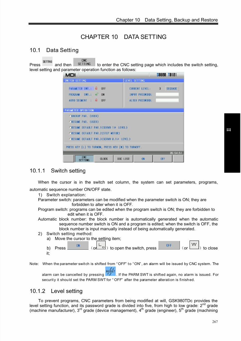
8/17/2019 980TDc CNC Turning Controller User Manual
http://slidepdf.com/reader/full/980tdc-cnc-turning-controller-user-manual 282/461
Chapter 10 Data Setting, Backup and Restore
267
O p er a t i on
CHAPTER 10 DATA SETTING
10.1 Data Setting
Press and then to enter the CNC setting page which includes the switch setting,level setting and parameter operation function as follows:
10.1.1 Switch setting
When the cursor is in the switch set column, the system can set parameters, programs,
automatic sequence number ON/OFF state.
1) Switch explanation:Parameter switch: parameters can be modified when the parameter switch is ON; they are
forbidden to alter when it is OFF.Program switch: programs can be edited when the program switch is ON; they are forbidden to
edit when it is OFF. Automatic block number: the block number is automatically generated when the automatic
sequence number switch is ON and a program is edited; when the switch is OFF, theblock number is input manually instead of being automatically generated.
2) Switch setting method:
a) Move the cursor to the setting item;
b) Press (or )to open the switch, press (or )to close
it;
Note: When the parameter switch is shifted from “OFF” to “ON” , an alarm will be issued by CNC system. The
alarm can be cancelled by pressing . If the PARM SWT is shifted again, no alarm is issued. For
securit y it should set the PARM SWT for “ OFF” after the parameter alteration is finished.
10.1.2 Level setting
To prevent programs, CNC parameters from being modified at will, GSK980TDc provides thelevel setting function, and its password grade is divided into five, from high to low grade: 2
nd grade
(machine manufacturer), 3rd
grade (device management), 4th grade (engineer), 5
th grade (machining
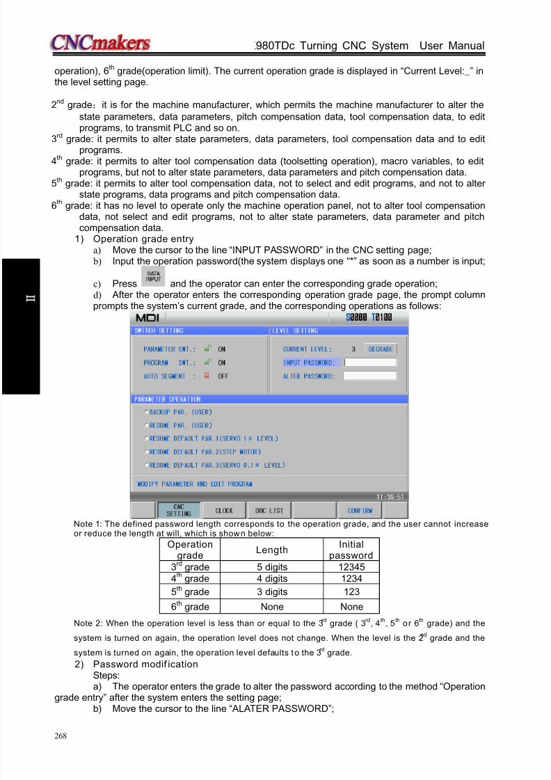
8/17/2019 980TDc CNC Turning Controller User Manual
http://slidepdf.com/reader/full/980tdc-cnc-turning-controller-user-manual 283/461
GSK980TDc Turning CNC System User Manual
268
O p er a t i on
operation), 6th
grade(operation limit). The current operation grade is displayed in “Current Level:_” inthe level setting page.
2nd
grade:it is for the machine manufacturer, which permits the machine manufacturer to alter the
state parameters, data parameters, pitch compensation data, tool compensation data, to editprograms, to transmit PLC and so on.
3rd grade: it permits to alter state parameters, data parameters, tool compensation data and to editprograms.
4th
grade: it permits to alter tool compensation data (toolsetting operation), macro variables, to editprograms, but not to alter state parameters, data parameters and pitch compensation data.
5th
grade: it permits to alter tool compensation data, not to select and edit programs, and not to alterstate programs, data programs and pitch compensation data.
6th
grade: it has no level to operate only the machine operation panel, not to alter tool compensationdata, not select and edit programs, not to alter state parameters, data parameter and pitchcompensation data.
1) Operation grade entrya) Move the cursor to the line “INPUT PASSWORD” in the CNC setting page; b) Input the operation password(the system displays one “*” as soon as a number is input;
c) Press and the operator can enter the corresponding grade operation;d) After the operator enters the corresponding operation grade page, the prompt columnprompts the system’s current grade, and the corresponding operations as follows:
Note 1: The defined password length corresponds to the operation grade, and the user cannot increaseor reduce the length at will, which is shown below:
Operationgrade
Length Initialpassword
3rd
grade 5 digits 12345
4th
grade 4 digits 1234
5th grade 3 digits 123
6th grade None None
Note 2: When the operation level is less than or equal to the 3rd
grade ( 3rd
, 4th
, 5th
or 6th
grade) and the
system is turned on again, the operation level does not change. When the level is the 2nd
grade and the
system is turned on again, the operation level defaults to the 3rd
grade.
2) Password modif icationSteps:
a) The operator enters the grade to alter the password according to the method “Operationgrade entry” after the system enters the setting page;
b) Move the cursor to the line “ALATER PASSWORD”;

8/17/2019 980TDc CNC Turning Controller User Manual
http://slidepdf.com/reader/full/980tdc-cnc-turning-controller-user-manual 284/461
Chapter 10 Data Setting, Backup and Restore
269
O p er a t i on
c) Input the new password, and then press ;d) The CNC prompts “ Input the new password again”;
e) Input the new password again and then press . When the two input passwordsare identical, the CNC prompts “Password has been altered, please save the new
password.” The password alteration is done successfully.
Note: The system prompts “ The new password is not identical with the confirmation” when the two
input passwords are not identical. At the moment, input the new password again.
3) Operation grade degradationThe degradation is to degrade from the high to the low, and its steps are shown below:
a) Input the password according the method of “Operation grade entry” after the systementers the setting page;
b) Move the cursor to the line “CURRENT LEVEL” and the system pops upas follows:
c) Press (or ), and the CNC prompts “Password degrades one grade”
as follows:

8/17/2019 980TDc CNC Turning Controller User Manual
http://slidepdf.com/reader/full/980tdc-cnc-turning-controller-user-manual 285/461
GSK980TDc Turning CNC System User Manual
270
O p er a t i on
d) Press (or ) again, and the degradation is done successfully as
follows:
Note 1: The degradation operation cannot be executed when the current level is the 6th
grade.
Note 2: The current password can be altered after degradation. When the system is in the high level, the
degradation can be executed to set to the low-level password.
10.1.3 Parameter operation
The parameter data (state parameter, data parameter) can be backup (stored) and recovered(read). Programs can be stored in the CNC when the backup or recovery is executed. The display is
shown below:
1) Option explanation:
Backup current parameters (user): the user to backup the CNC data (store)
Resume backup parameters(user): the user resumes the backup data (read)
Resume parameter 1(servo 1u level): the user reads the original parameter data matched

8/17/2019 980TDc CNC Turning Controller User Manual
http://slidepdf.com/reader/full/980tdc-cnc-turning-controller-user-manual 286/461
Chapter 10 Data Setting, Backup and Restore
271
O p er a t i on
with the servo drive with the precision 1um
Resume parameter 2(stepper 1u level): the user reads the original parameter data matched
with the stepper drive
Resume parameter 3(servo 0.1u level): the user reads the original parameter data matched
with the servo drive with the precision 0.1um
Note: When the level is the 2nd
grade, the backuping current parameters (user ) and resuming backup
parameters (user) become backuping current parameters (machine manufacturer) and resuming backup
parameters (machine manufacturer), which is used to backup and resume the manufacturer’s data.
2) Operation methods:a) Open the parameter switch;
b) Press to enter the MDI mode, move the cursor the required item;
c) Press (or simultaneously press , ), and the system prompts
whether to confirm the current operation.
d) Press again(or ), and the system prompts the backup or resume is
done successfully. When the recovery is done, the system prompts power-on again.
Note: Don’t turn off the system and execute other operations when the backup or resuming is executed.
10.2 Clock Sett ing
Press and then to enter the system clock page. The operator can alter thecurrent data and time as follows:
Press to enter the alteration mode, press , to move the cursor to the required
modification (Year/Month/Date/Minute/Second), input directly numbers, and press , thento escape from the alteration mode.

8/17/2019 980TDc CNC Turning Controller User Manual
http://slidepdf.com/reader/full/980tdc-cnc-turning-controller-user-manual 287/461
GSK980TDc Turning CNC System User Manual
272
O p er a t i on
10.3 Graphic Display
Press key to enter the path page as follows:
Press to open the next page menu as follows:
1) The START, STOP and CLEAR of the graphic path
In the path display page, press the (or ) and the system starts the drawing;
press (or ) , it stops drawing; press (or ), it clears the current
graphic path.
When the path exceeds the display range during automatic graph, the system regulate the
graphic center following the tool nose position in real time. Press (or ) and the
display area is locked, the system does not regulate the graphic center on when the path

8/17/2019 980TDc CNC Turning Controller User Manual
http://slidepdf.com/reader/full/980tdc-cnc-turning-controller-user-manual 288/461
Chapter 10 Data Setting, Backup and Restore
273
O p er a t i on
exceeds the display area. Press (or ) and the system releases the lock.
2) Scaling up and down
In the path display page, press (or ), (or ), the system scales
up/down the path in real time. Press (or ) each time, the graphic path is scaled up
2 fold, press (or ) each time, the graphic path is scaled down 2 fold.
3) Path disp lay moving
In the graph display page, press the cursor movement key to move the graphic path.
Press (or )to adjust mobile intervals.4) Graphic attribution display
In the path display page, press (or ) to display the graphic attribution window,including the current coordinate system, translation position, scaling and mobile interval. It is shown
below:
Press (or )again to close the graph attribution window.
5) Graphic parameter meaning
Coordinate system setting: 8 types of graphic paths can be displayed in this GSK980TDc CNC
system according to the front or rear tool post coordinate system, and there is 4 kinds of path as
follows: (switch X, Z axis by pressing or )
Bit parameter No.175
Bit1 Bit0Graphic path coordinate display

8/17/2019 980TDc CNC Turning Controller User Manual
http://slidepdf.com/reader/full/980tdc-cnc-turning-controller-user-manual 289/461
GSK980TDc Turning CNC System User Manual
274
O p er a t i on
Bit parameter No.175
Bit1 Bit0Graphic path coordinate display
0 0
0 1
1 0

8/17/2019 980TDc CNC Turning Controller User Manual
http://slidepdf.com/reader/full/980tdc-cnc-turning-controller-user-manual 290/461
Chapter 10 Data Setting, Backup and Restore
275
O p er a t i on
Bit parameter No.175
Bit1 Bit0Graphic path coordinate display
1 1
10.4 Parameter Sett ing
Parameter setting can adjust related characteristics of the drive unit and machine.
Press to enter Parameter interface which includes , , ,
as follows:
10.4.1 State parameter
1) Byte alteration: a) Turn on the parameter switch;
b) Enter the MDI mode;
c) Move the cursor to the parameter number to be set:

8/17/2019 980TDc CNC Turning Controller User Manual
http://slidepdf.com/reader/full/980tdc-cnc-turning-controller-user-manual 291/461
GSK980TDc Turning CNC System User Manual
276
O p er a t i on
Method 1: Press or to enter the page containing the parameter to be set, press
or key to move the cursor to the parameter number to be set;
Method 2: Press (or ) , and input the parameter number in the
pop-up dialogue box, at last, press .
4) Key in a new parameter value;
5) Press key, the parameter value is entered and displayed.
6) For security, the PARM SWT needs to be set to OFF after all parameter settings are
finished.
Example:Set the bit parameter No.001 Bit 3(STEP/MPG) to 1, and the other bits remain unchanged.
Move the cursor to No.001, input 00011000 by sequence according to the above steps. The
display is shown below:
Press to finish the parameter alteration. The page is shown below:

8/17/2019 980TDc CNC Turning Controller User Manual
http://slidepdf.com/reader/full/980tdc-cnc-turning-controller-user-manual 292/461
Chapter 10 Data Setting, Backup and Restore
277
O p er a t i on
2) Alteration by bit:
a) Turn on the parameter switch;
b) Enter the MDI mode;
c) Move the cursor to the parameter number to be set(the method is referred to Section
10.4.1 Step c);
d) Press to enter the bit alteration mode, at the moment, some bit of the parameter
is backlighted. Press or to move the cursor to the bit to be altered, then key in 0 or
1;
e) After all parameters setting is finished, the PARM SWT needs to be set to OFF for
security.
Note: After the system enters some bit of the parameter, is pressed to escape from the
alteration mode, and the cursor stops the parameter number .
Example:
Set the Bit3 of the bit parameter No.001 to 1, and the other bits remains unchanged.
Move the cursor to No.001 according to the above steps, press to skip to some bit of theparameter, and move the cursor to Bit3. The display is shown below:

8/17/2019 980TDc CNC Turning Controller User Manual
http://slidepdf.com/reader/full/980tdc-cnc-turning-controller-user-manual 293/461
GSK980TDc Turning CNC System User Manual
278
O p er a t i on
Input 1, and the parameter alteration is done.
10.4.2 Data parameter, pitch compensation
1) Turn on the parameter switch;
2) Enter the MDI mode;
3) Move the cursor to the No. of the parameter to be set;
4) Key in the new parameter value;
5) Press key, the value is entered and displayed;
6) After all parameters setting is finished, the PARM SWT needs to be set to OFF for security.
Explanation: The screw-pitch parameter can only be altered under the 2 level password author ity.
Example 1: set the data parameter No.027 to 7600.

8/17/2019 980TDc CNC Turning Controller User Manual
http://slidepdf.com/reader/full/980tdc-cnc-turning-controller-user-manual 294/461
Chapter 10 Data Setting, Backup and Restore
279
O p er a t i on
Move the cursor to No.027 by the steps above, key in 7600 by sequence as follows:
Press to finish the alteration. The display is shown below:
Example 2: set X value of the screw-pitch parameter No.000 to 12.
Move the cursor to screw-pitch parameter No.000 by the steps above, key in 12 in order as
follows:

8/17/2019 980TDc CNC Turning Controller User Manual
http://slidepdf.com/reader/full/980tdc-cnc-turning-controller-user-manual 295/461
GSK980TDc Turning CNC System User Manual
280
O p er a t i on
Press key to finish the alteration. The display page is shown below:
10.4.3 Often used parameters
Press to enter parameter interface, and press to enter the often used parameterpage. The page is shown below:

8/17/2019 980TDc CNC Turning Controller User Manual
http://slidepdf.com/reader/full/980tdc-cnc-turning-controller-user-manual 296/461
Chapter 10 Data Setting, Backup and Restore
281
O p er a t i on
The user can add the often used state parameter, data parameters to the often used parameters
to get the convenient search and alteration.
1) Adding often used parameters
a) In the state parameter page, press to enter the state parameter menu. Thepage is shown below:
b) Move the cursor to the required addition parameter number (taking example of No.003),
press , and the current parameter becomes the often used. The added isautomatically sorted in the last line. The page is shown below:

8/17/2019 980TDc CNC Turning Controller User Manual
http://slidepdf.com/reader/full/980tdc-cnc-turning-controller-user-manual 297/461
GSK980TDc Turning CNC System User Manual
282
O p er a t i on
At the moment, pressing , , can adjust the parameter sortingposition.
Note: The addit ion method of data parameter is similar to that of state parameter.
2) Sorting often used parameters
Pressing , can move the parameter where the current cursor is. Pressing
sorts all often used parameter in sequence number.
3) Removing often used parameters
Move the cursor to the required parameter in the often used parameter page. Press
and the current often used parameter is removed. Press and all often used parameters are removed.
4) Altering often used parameter
Parameters can be altered directly in the often used parameter page. Its alteration
method is the same that of state parameter and data parameter. Its value is also refreshed
in the state parameter or data parameter page.

8/17/2019 980TDc CNC Turning Controller User Manual
http://slidepdf.com/reader/full/980tdc-cnc-turning-controller-user-manual 298/461
Chapter 13 Communication
283
O p er a t i on
CHAPTER 11 U OPERATION FUNCTION
11.1 File Management Function Introduct ion
GSK980TDc has the file management function to execute the file copy, data backup, dataresume, the system upgrading (2nd grade) and so on.
In any states, press to select the setting interface, press to enter the filemanagement page. Insert U disk and the system automatically identifies it. The system displays the
icon at the lower right bottom of the system after it sucessfully identifies the icon as follows:
Press the soft key (or ) to select the CNC catalog or the U disk catalog, and
press , to move the line where the current cursor is.
11.2 Often Used File Operation Function Introduction
11.2.1 File extension and return
1) Move the cursor to the required extension file, press to extend it as follows:
Display the userparameters, toolcompensation, pitch
compensation, PLCprograms, partprogram and so onin the CNC catalogwindow
Display all filesin the U diskcatalog
window

8/17/2019 980TDc CNC Turning Controller User Manual
http://slidepdf.com/reader/full/980tdc-cnc-turning-controller-user-manual 299/461
GSK980TDc Turning CNC System User Manual
284
O p er a t i on
2) Move the cursor to the target file, press to return the previous catalog of the current
file as follow:
11.2.2 File selection and cancellation of file selectionTake an example of U:\gsk980tdc_backup\user\NCPROG\O0010.CNC to introduce the selection andcancellation.
1) Press to select setting interface, press to enter the file managementpage as follows:

8/17/2019 980TDc CNC Turning Controller User Manual
http://slidepdf.com/reader/full/980tdc-cnc-turning-controller-user-manual 300/461
Chapter 13 Communication
285
O p er a t i on
2) Move the cursor to O0101.CNC as follows:
3) Press (or )to select O0101.CNC as follows:
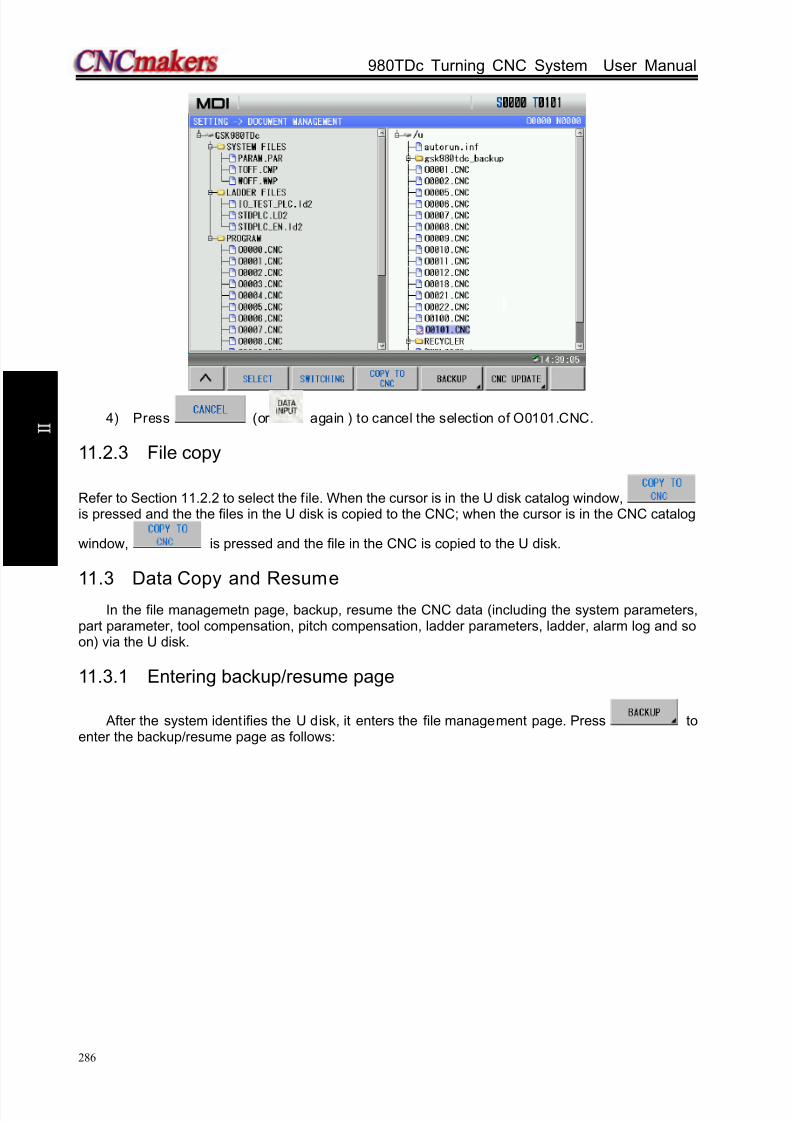
8/17/2019 980TDc CNC Turning Controller User Manual
http://slidepdf.com/reader/full/980tdc-cnc-turning-controller-user-manual 301/461
GSK980TDc Turning CNC System User Manual
286
O p er a t i on
4) Press (or again ) to cancel the selection of O0101.CNC.
11.2.3 File copy
Refer to Section 11.2.2 to select the file. When the cursor is in the U disk catalog window,is pressed and the the files in the U disk is copied to the CNC; when the cursor is in the CNC catalog
window, is pressed and the file in the CNC is copied to the U disk.
11.3 Data Copy and Resume
In the file managemetn page, backup, resume the CNC data (including the system parameters,part parameter, tool compensation, pitch compensation, ladder parameters, ladder, alarm log and soon) via the U disk.
11.3.1 Entering backup/resume page
After the system identifies the U disk, it enters the file management page. Press toenter the backup/resume page as follows:

8/17/2019 980TDc CNC Turning Controller User Manual
http://slidepdf.com/reader/full/980tdc-cnc-turning-controller-user-manual 302/461
Chapter 13 Communication
287
O p er a t i on
11.3.2 Backup/resume operation
1) Press , , , to move the cursor to the required option;
2) Press (or )to select the required option to be backup/resumed;
3) Press (or ) to cancel the selection when the cursor has been in theselected option;
4) Press or to select or cancel all selection;
5) Press (or )to execute the current selected.Note 1: Data which has been backup or has been done to store in the U disk can be resumed.Note 2: When the cursor is in the “BACKUP OPTION” column, all options in the the “RESUME OPTION”column cannot be selected; when the cursor is in the “ RESUME OPTOIN”, all options in the “ BACKUPOPTION” column cannot be selected;
Note 3: Pressing executes operations only in the column where the cursor is. When the cursoris in “ BACKUP OPTION” column, the resume operation i s executed. The backup, resume cannot be executedsimultaneously.
11.3.3 Operation path selection
When the user uses the U disk to execute the CNC data backup, the CNC creates a backup file
“gsk980tdc_backup” in the root catalog of the U disk. The backup file includes two backup data “U:\
gsk980tdc_backup\user” and “U:\ gsk980tdc_backup\serial number” (it is created by the system’s
serial number). When the user uses one U disk to execute data backup of many CNC systems, the
data in “U:\ gsk980tdc_backup\user” is replaced by the new but data in “U:\ gsk980tdc_backup\serial

8/17/2019 980TDc CNC Turning Controller User Manual
http://slidepdf.com/reader/full/980tdc-cnc-turning-controller-user-manual 303/461
GSK980TDc Turning CNC System User Manual
288
O p er a t i on
number” remains unchanged.
For the above reason, the user should execute the operation path selection during resuming
data:
Default path :U:\ gsk980tdc_backup\user
Serial number path:U:\ gsk980tdc_backup\serial number
Example: backup/resume data of many CNC systems
When the user backups the system A (serial number CT0000001), the generated file by data
backup is “U:\gsk980tdc_backup\CT0000001” and “U:\gsk980tdc_backup\user”; When the user
backups the system B(serial number CT0000002) , the generated file by data backup is
“U:\gsk980tdc_backup\CT0000002”. The “U:\gsk980tdc_backup\user” generated by A is replaced
automatically by the same name of the system B. At the moment, the user can execute the operation
path selection when it executes the data resume operation of the system A:
1) When the previous data of the system A is resumed, the operation path is :
“U:\gsk980tdc_backup\CT0000001”;
2) When the backup data of the system B is copied to the system A, the operation path is:
“U:\gsk980tdc_backup\CT0000002” or default path;
Press and appear the dialog box of operation path selection, and then select the
operation path by , when the cursor is in the resume column. Taking an example ofselecting the default path, the display is shown below:
11.3.4 Format of data backup/resume file
File Extension name
Content
Parameter file PARAM .PARState parameters, data
parametersTool compensationdata
TOFF .CMP Tool offset, tool wear
Pitch compensation WOFF .WMP Pitch compensation

8/17/2019 980TDc CNC Turning Controller User Manual
http://slidepdf.com/reader/full/980tdc-cnc-turning-controller-user-manual 304/461
Chapter 13 Communication
289
O p er a t i on
Alarm log Alarm.his .his Alarm log
PLC programNorequirements
.ld2 PLC programs
PLC parameter plcpar .dat K, D, DT, DC parameters
Part program O0000~O9999 .CNC Part programs
11.3.5 Level explanation of data backup/resume operation
Systemparameters
More than the 5th grade password
Toolcompensation
data
More than 5th grade(including the 5
th grade)
password
Pitchcompensation
More than 5th grade(including the 5th grade)password
Alarm log More than 5th grade(including the 5
th grade)
password
PLC programs More than 5th
grade(including the 5th
grade)password
PLC programs More than 5th grade(including the 5th grade)password
Backupoperation
Part programs More than 5th grade(including the 5th grade)password
Systemparameters
More than 3rd grade(including the 3rd grade)password
Toolcompensation
data
More than 5th grade(including the 5th grade)password
Pitch
compensation
More than 2nd
grade(including the 2nd
grade)
passwordPLC programs More than 5
th grade(including the 5
th grade)
password
PLCparameters
More than 2nd grade(including the 2nd grade)password
Resumeoperation
Part programs More than 4th grade(including the 4th grade)password
11.4 Notes
The user should pay more attention to the followings during executing the data backup/resume
operation:1) Need more than the 2nd grade password(including the 2nd grade) to resume more than
(including be equal to) 9000 part programs;
2) Backup/resume operation must be in MDI mode;
3) When the user executes the data backup operation, the system automatically replaces all
files in “U:\gsk980tdc_backup\user”, the user should save them as when they cannot be
replaced;
4) Stop part programs running before data backup/resume;
5) They must not stop unless the data backup/resume operation is completed;
6) The system is turned on again after the data resume is done.

8/17/2019 980TDc CNC Turning Controller User Manual
http://slidepdf.com/reader/full/980tdc-cnc-turning-controller-user-manual 305/461
GSK980TDc Turning CNC System User Manual
290
O p er a t i on
CHAPTER 12 COMMUNICATION
12.1 GSK980TDc Communication Software GSKComm
GSKComm is an allocated project administrator. It can execute the upload/download between
PC and CNC, conveniently transmit batch with easy operation, high communication efficiency and
reliability.
The followings introduce communication transmission and setting between GSK980TDc and
GSKComm. Refer to GSKComm explanations about GSKComm communication software functions.
12.1.1 GSKComm’s system (PC) requirements
Hardware: general PC with RS232 serial port, serial communication cable (3-wire)
Operation system: Microsoft Windows 98/2000/XP/2003
12.1.2 Software interface
Interface after GSKComm’s initial run:
Fig. 12-1 file download(PC→CNC)interface
GSKComm software takes an administrator as a unit to complete management. When it run
firstly, it does not upload project files, at the moment, the user should create an project program or
upload project to execute the communication operation. The display is shown below after the an
project is created:

8/17/2019 980TDc CNC Turning Controller User Manual
http://slidepdf.com/reader/full/980tdc-cnc-turning-controller-user-manual 306/461
Chapter 13 Communication
291
O p er a t i on
At the mode, the user can receive the files from the CNC to the current project or send files in the
current project to the CNC.
12.1.3 Receiving files (CNC→PC)
Click the option [Receive files from CNC] in [Communication] and GSKComm can receive files
from the CNC after the current project is selected as follows:
After [Receive Files ] is clicked, a dialog box about receiving files from the CNC, the required files
from the CNC including part programs, tool compensation (TOFF. CMP), pitch compensation
(WOFF.WMP), parameters (PARAM.PAR).
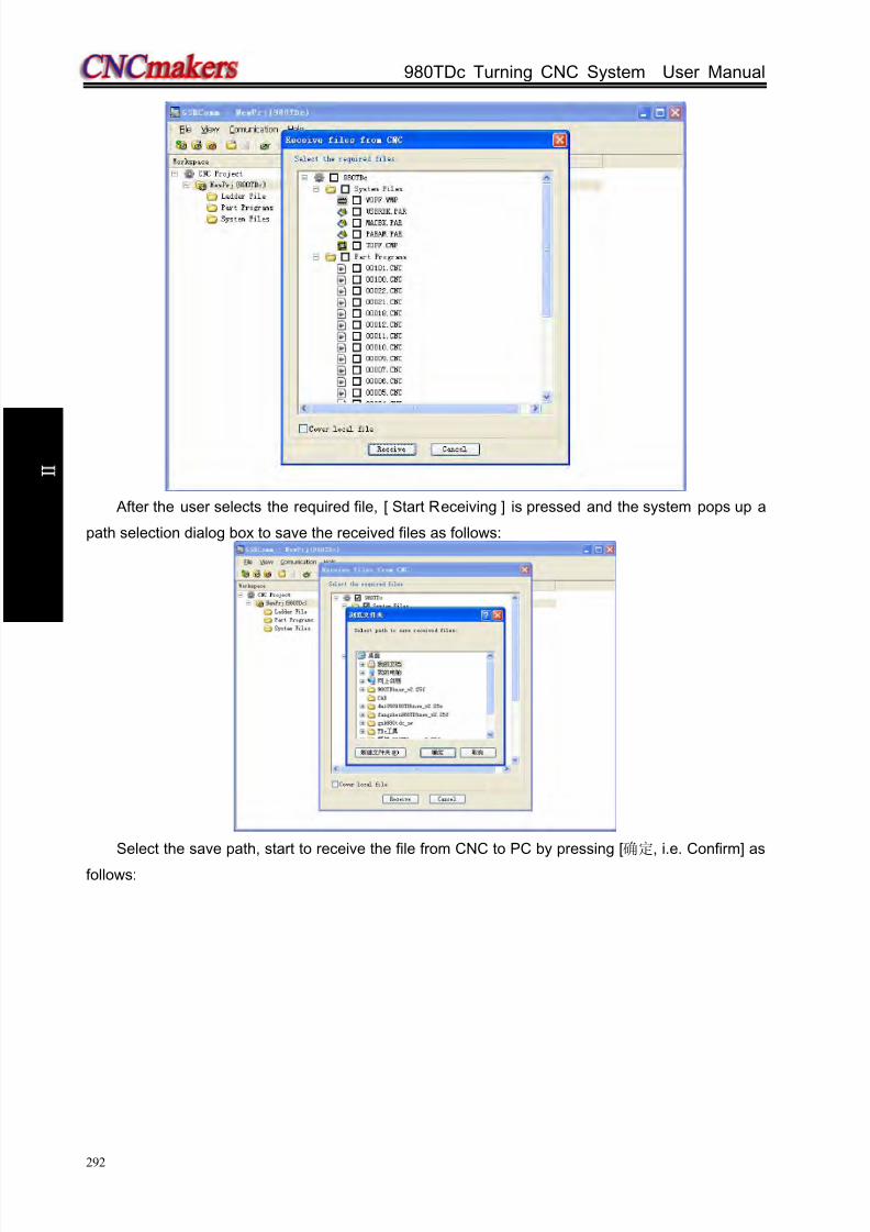
8/17/2019 980TDc CNC Turning Controller User Manual
http://slidepdf.com/reader/full/980tdc-cnc-turning-controller-user-manual 307/461
GSK980TDc Turning CNC System User Manual
292
O p er a t i on
After the user selects the required file, [ Start Receiving ] is pressed and the system pops up a
path selection dialog box to save the received files as follows:
Select the save path, start to receive the file from CNC to PC by pressing [确定, i.e. Confirm] as
follows:

8/17/2019 980TDc CNC Turning Controller User Manual
http://slidepdf.com/reader/full/980tdc-cnc-turning-controller-user-manual 308/461
Chapter 13 Communication
293
O p er a t i on
After the receiving is done, the system displays below:
12.1.4 Sending files (CNC→PC)
After the current project file is selected, the user clicks [Send projects to CNC] in the menu
[Communication], and so the receiving file from CNC is done. A dialog box to send files to CNC is
popped up as follows:
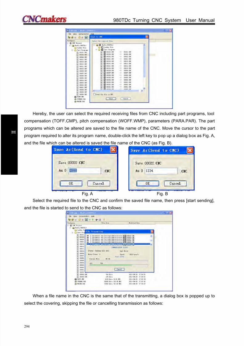
8/17/2019 980TDc CNC Turning Controller User Manual
http://slidepdf.com/reader/full/980tdc-cnc-turning-controller-user-manual 309/461
GSK980TDc Turning CNC System User Manual
294
O p er a t i on
Hereby, the user can select the required receiving files from CNC including part programs, tool
compensation (TOFF.CMP), pitch compensation (WOFF.WMP), parameters (PARA.PAR). The part
programs which can be altered are saved to the file name of the CNC. Move the cursor to the part
program required to alter its program name, double-click the left key to pop up a dialog box as Fig. A,
and the file which can be altered is saved the file name of the CNC (as Fig. B).
Fig. A Fig. B
Select the required file to the CNC and confirm the saved file name, then press [start sending],
and the file is started to send to the CNC as follows:
When a file name in the CNC is the same that of the transmitting, a dialog box is popped up to
select the covering, skipping the file or cancelling transmission as follows:

8/17/2019 980TDc CNC Turning Controller User Manual
http://slidepdf.com/reader/full/980tdc-cnc-turning-controller-user-manual 310/461
Chapter 13 Communication
295
O p er a t i on
When the part program name which is has the same that of the transmitted file, the covering
cannot be done, otherwise, the system pops up the wrong prompt as follows:
12.1.5 Part program management
Select the current project file, then click [Manage Part Programs] in the menu [Communication] ,
and the part programs in the CNC are managed. The system pops up a dialog box to manage part
programs in the CNC as follows:

8/17/2019 980TDc CNC Turning Controller User Manual
http://slidepdf.com/reader/full/980tdc-cnc-turning-controller-user-manual 311/461
GSK980TDc Turning CNC System User Manual
296
O p er a t i on
Press [Delete File] and the selected part programs are deleted in the CNC after the required
programs are selected.
Note: The program being used in the CNC cannot be deleted.
12.2 Preparatory before Communication
12.2.1 Communication cable connection
DB9 male plug is inserted into CN51 communication interface of the CNC, DB9 female plug is
inserted in to DB9-male serial port (COM0 or COM1) of PC. Connect the communication cable when
PC and CNC are turned off.
12.2.2 Communication setting baud rate
Setting the baud rate of communication ensures that the baud rate of PC is the same that of the
CNC communication.
The communication baud of the serial port is set by No.044; click [Communication Setup] in the
menu [Communication] and the system pops up a dialog box as follows:
Set the serial port and baud rate. The baud rate should be not less than 4800 when the data istransmitted between CNC and PC, the factory setting is :115200.

8/17/2019 980TDc CNC Turning Controller User Manual
http://slidepdf.com/reader/full/980tdc-cnc-turning-controller-user-manual 312/461
Chapter 13 Communication
297
O p er a t i on
Note 1: GSK980TDc has no network function, and so it has no network setting in its communication.
Note 2: Stop machining when the machining i s being done to get the stable communication.
Note 3: Must not turn o ff during the data transmission, otherwise, it causes the mistaken data transmission.

8/17/2019 980TDc CNC Turning Controller User Manual
http://slidepdf.com/reader/full/980tdc-cnc-turning-controller-user-manual 313/461
GSK980TDc Turning CNC System User Manual
298
O p er a t i on
CHAPTER 13 MACHINING EXAMPLES
Machine a part by a bar stock with dimension Φ136mm×180 mm, as follows:
4 ×
×
×
Z
Fig. 13-1
Machine it with 4 tools as follows:
Tool number Tool shape Explanation
No. 1 Outer circle rough turning tool
No. 2 Outer circle finish turning tool
No. 3 Grooving tool, tool width 3mm

8/17/2019 980TDc CNC Turning Controller User Manual
http://slidepdf.com/reader/full/980tdc-cnc-turning-controller-user-manual 314/461
Chapter 14 Machining Example
299
O p er a t i on
Tool number Tool shape Explanation
No. 4 Threading tool, tool nose angle 60°
13.1 Programming
Set up the workpiece coordinate system as Fig.13-1 according to the machining process and the
codes introduced in this manual. The programming steps are as follows:
O0001; Name of the part program
N0000 G0 X150 Z50; Position to the safety height for tool change
N0005 M12; Clamp the chuck
N0010 M3 S800; Start the spindle with speed 800
N0020 M8; Turn on the cooling
N0030 T0101; Change for the No. 1 tool
N0040 G0 X136 Z2; Approach the part
N0050 G71 U0.5 R0.5 F200; Cut depth 2mm and retract 1mm
N0055 G71 P0060 Q0150 U0.25
W0.5;
0.25mm pre-reserved in X axis, 0.5mm
machining allowance in Z axis
N0060 G0 X16; Approach to the end face of the part
N0070 G1 Z-23; Cut the Φ16 outer circle
N0080 X39.98; Cut the end face
N0090 W-33; Cut the Φ39.98 outer circle
N0100 X40; Cut the end face
N0105 W-30; Cut the Φ40 outer circle
N0110 G3 X80 W-20 R20; Cut the convex arc
N0120 G2 X120 W-20 R20; Cut the concave arc
N0130 G1 W-20; Cut the Φ120 outer circle
N0140 G1 X130 W-5; Cut the cone
N0150 G1 W-25; Cut the Φ130 outer circle
N0160 G0 X150 Z185; Rough cut end and back to the tool change
point
N0170 T0202; Change for the No.2 tool and execute its
offset
N0180 G70 P0060 Q0150; Fine cut cycle

8/17/2019 980TDc CNC Turning Controller User Manual
http://slidepdf.com/reader/full/980tdc-cnc-turning-controller-user-manual 315/461
GSK980TDc Turning CNC System User Manual
300
O p er a t i on
N0190 G0 X150 Z185; Rough cut end and back to the tool change
point
N0200 T0303; Change for the No.3 tool and execute its
offset
N0210 G0 Z-56 X42; Approach to the part
N0220 G1 X30 F100; Cut the Φ30 groove
N0230 G1 X37 F300; Return
N0240 G1 X40 W1.5; Chamfering
N0250 G0 X42 W30; Keep the width of the grooving
N0260 G1 X40 ;
N0262 G1 X37 W1.5; Chamfering
N0264 G1 X10; Cut the Φ10 groove
N0266 G0 X17 Z-1;
N0268 G1 X16;
N0270 G1 X14 Z0 F200; Chamfering
N0280 G0 X150 Z50; Return to the tool change point
N0290 T0404 S100; Changing for the No. 4 tool and set the
spindle speed for 100
N0300 G0 X42 Z-20; Approach the part
N0310 G92 X39 W-34 F3; Thread-cutting cycle
N0320 X38; Feed 1mm for the 2nd
cutting
N0320 X37; Feed 1mm for the 3rd cutting
N0330 X36.4; Feed 0.6mm for the 4th cutting
N0332 X36; Feed 0.4mm for the 5th cutting
N0340 G0 X150 Z50; Return to the tool change point
N0350 T0100 U0 W0; Change for the No.1 tool and execute its
offset
N0360 M5; Turn off the spindle
N0370 M9; Turn off cooling
N0380 M13; Unclamp the chuck
N0390 M30; Program ends

8/17/2019 980TDc CNC Turning Controller User Manual
http://slidepdf.com/reader/full/980tdc-cnc-turning-controller-user-manual 316/461
Chapter 14 Machining Example
301
O p er a t i on
13.2 Program Input
13.2.1 View a saved program
Press to enter program interface , and press to enter the local catalog page asfollows:
In above window the names of the programs saved can be viewed for renaming the new
program.
13.2.2 Creating a new program
Enter the local catalog page in Edit mode, press address key , choose a name that is not
same with the ones in this window (i.e. 0001), key in the number key , , , and
to create a new program as follows:

8/17/2019 980TDc CNC Turning Controller User Manual
http://slidepdf.com/reader/full/980tdc-cnc-turning-controller-user-manual 317/461
GSK980TDc Turning CNC System User Manual
302
O p er a t i on
Input the characters of the above edit program one by one and the editing program is done.
13.3 Checkout a Program
13.3.1 Graphic setting
Press to enter graph interface as follows:
13.3.2 Program check
Press to enter graph display page. Press to enter Auto mode, press ,
, to make the auxiliary function lock indicator , machine lock indicator , and dry
run indicator to enter the corresponding state. Press to start the drawing,
press to automatically run programs, check the program accuracy by displaying the tool motion
path, and the display page is the following after the run is completed:
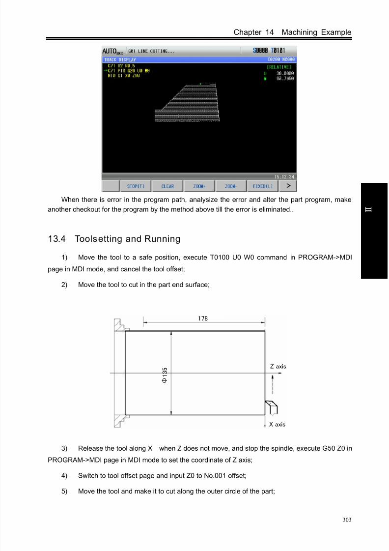
8/17/2019 980TDc CNC Turning Controller User Manual
http://slidepdf.com/reader/full/980tdc-cnc-turning-controller-user-manual 318/461
Chapter 14 Machining Example
303
O p er a t i on
When there is error in the program path, analysize the error and alter the part program, make
another checkout for the program by the method above till the error is eliminated..
13.4 Toolsetting and Running
1) Move the tool to a safe position, execute T0100 U0 W0 command in PROGRAM->MDI
page in MDI mode, and cancel the tool offset;
2) Move the tool to cut in the part end surface;
Z axis
X axis
178
Φ 1 3 5
3) Release the tool along X when Z does not move, and stop the spindle, execute G50 Z0 in
PROGRAM->MDI page in MDI mode to set the coordinate of Z axis;
4) Switch to tool offset page and input Z0 to No.001 offset;
5) Move the tool and make it to cut along the outer circle of the part;

8/17/2019 980TDc CNC Turning Controller User Manual
http://slidepdf.com/reader/full/980tdc-cnc-turning-controller-user-manual 319/461
GSK980TDc Turning CNC System User Manual
304
O p er a t i on
6) Release the tool along Z when X does not move, and stop the spindle, measure the
dimensions of the outer circle of the part (e.g. The measuring value is 135mm);
7) Execute G50 X135 command in PROGRAM>MDI page in MDI mode to set the coordinate
of X axis;
8) Switch to tool offset page, and input X135 to No.001 offset;
9) Move the tool to a safe position, and change No. 002 tool;
10) Start the spindle and move the tool to the toolsetting point, as A point in the following figure;
11) Switch to TOOL OFFSET window, move the cursor to No.002 offset and input X135 Z0;
12) Move the tool to a safe position, and change the No. 003 tool ;
13) Start the spindle and move the tool to the toolsetting point, as A point in the following figure;
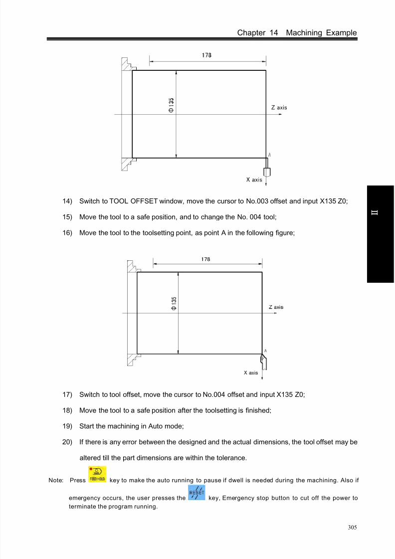
8/17/2019 980TDc CNC Turning Controller User Manual
http://slidepdf.com/reader/full/980tdc-cnc-turning-controller-user-manual 320/461
Chapter 14 Machining Example
305
O p er a t i on
14) Switch to TOOL OFFSET window, move the cursor to No.003 offset and input X135 Z0;
15) Move the tool to a safe position, and to change the No. 004 tool;
16) Move the tool to the toolsetting point, as point A in the following figure;
17) Switch to tool offset, move the cursor to No.004 offset and input X135 Z0;
18) Move the tool to a safe position after the toolsetting is finished;
19) Start the machining in Auto mode;
20) If there is any error between the designed and the actual dimensions, the tool offset may be
altered till the part dimensions are within the tolerance.
Note: Press key to make the auto running to pause if dwell is needed during the machining. Also if
emergency occurs, the user presses the key, Emergency stop button to cut off the power to
terminate the program running.

8/17/2019 980TDc CNC Turning Controller User Manual
http://slidepdf.com/reader/full/980tdc-cnc-turning-controller-user-manual 321/461
C onn e c t i on
Connection

8/17/2019 980TDc CNC Turning Controller User Manual
http://slidepdf.com/reader/full/980tdc-cnc-turning-controller-user-manual 322/461
Chapter 1 Installation Layout
307
CHAPTER 1 NSTALLATION LAYOUT
1.1 GK980TDc System Connect ion
1.1.1 GK980TDc, GSK980TDc-V rear cover interface layout
AXIS 5 SPINDLE
+5V
GND
N
L
INPUT
CN61
+12V
CN11
AXIS X
OUTPUT
CN62 CN15
CN13 CN12
AXIS Z AXIS Y
COM PORT
CN51
POWER SUPPLY
CN1
CN31
CN21CN14
AXIS 4 ENCODER
+5V
+5V
+5V
0V
-12V
0V
0V+24V
+24V
+12V
-12V
GSK-PB2
Power Supply
MPG
communication
Fig. 1-1 GSK980TDc rear cover interface layout
CN15
INPUT
CN61
OUTPUT
CN62
AXIS Y
CN13
AXIS Z
CN12
AXIS X
COM PORT
CN11
CN14
AXIS 4
CN21
ENCODER
MPG
CN51
+12V+24V -12V
CN31
+5V +5V
0V 0V +5V0V
CN1
Fig.1-2 GSK 980TDc-V rear cover interface layout

8/17/2019 980TDc CNC Turning Controller User Manual
http://slidepdf.com/reader/full/980tdc-cnc-turning-controller-user-manual 323/461
GSK980TDc Turning CNC System User Manual
308
C onn e c t i on
1.1.2 Interface explanation
Power box: GSK-PB2, for +5V, +24V, +12V, -12V, GND power supply
Filter(optional): Input terminals for 220V AC power, PE terminal for grounding, output
terminals to L, N terminals of GSK-PB2 power box
CN1: power supply interface CN11: X axis,pin15 D female, connect with X drive unit
CN12: Y axis,pin15 D female, connect with Y drive unit
CN13: Z axis,pin15 D female, connect with Z drive unit
CN14: 4th axis,pin15 D female, connect with 4th drive unit
CN15: spindle, pin 25 D female, connect with spindle drive unit
CN21: encoder, pin15 D male, connect with spindle encoder
CN31: MPG, pin26 D male, connect with MPG
CN51: communication, pin9 D female, connect PC RS232 interface
CN61: input, pin44 D male, connect with machine input
CN62: output, pin44 D female, connect with machine output
1.2 GSK980TDc Installation
1.2.1 GSK980TDc external dimensions
See appendix Ⅰ, Ⅱ.
1.2.2 Preconditions of the cabinet installation
The dust, cooling liquid and organic resolution should be effectively prevented from entering the
cabinet;
The designed distance between the CNC back cover and the cabinet should be not less than
20cm, the inside and outside temperature difference of the cabinet should be not more than 10
when the cabinet inside temperature rises;
Fans can be fixed in the cabinet to ventilate it;
The panel should be installed in a place where the cooling can’t splash;
The external electrical interference should be taken into consideration in cabinet design to
prevent it from interfering the CNC system.
1.2.3 Measures against interferenceIn order to insure the CNC stable working, the anti-interference technology such as space
electromagnetic radiation shielding, impact current absorbing, power mixed wave filtering are
employed in CNC design. And the following measures are necessary during CNC connection:
1. Make CNC far from the interference devices (inverter, AC contactor, static generator,
high-voltage generator and powered sectional devices etc.);
2. To supply the CNC via an isolation transformer, the machine with the CNC system should be
grounded, the CNC and drive unit should be connected with independent grounding wires at
the grounding point;
3. To inhibit interference: connect parallel RC circuit at both ends of AC winding (Fig. 1-3a), RC
circuit should approach to inductive loading as close as possible; reversely connect parallel
freewheeling diode at both ends of DC winding (Fig. 1-3b); connect parallel surge absorber at
the ends of AC motor winding (Fig. 1-3c);

8/17/2019 980TDc CNC Turning Controller User Manual
http://slidepdf.com/reader/full/980tdc-cnc-turning-controller-user-manual 324/461
Chapter 1 Installation Layout
309
C onn e c t i on
a) b) c)
Fig. 1-3
4. The CNC leadout cables use the twisted shield cable or shield cable, the cable shield tier is
grounded by an terminal at CNC side, signal cable should be as short as possible;
5. To reduce the mutual interference among the CNC signal cables, and among the strong
current, the wiring should follow the following:
Table 1-1 The Wiring requirement
Group Cable type Wiring requirement
A
AC power cable Tie up A group cables with a clearance at least 10cm
from that of B, C groups, or shield A group cables from
electromagnetism
AC coil
AC contactor
B
DC coil(24VDC)
Tie up B and A group cables separately or shield B
group cables; and the further B group cables are from
that of C group, the better it is
DC relay(24VDC)Cables between CNC and
strong-power cabinet
Cables between CNC and
machine
C
Cables between CNC and
servo drive unit Tie up C and A group cables separately, or shield C
group cables; and the cable distance between C group
and B group is at least 10cm and they are twisted pair
cables.
Position feedback cable
Position encoder cable
Handwheel(
MPG)
cableOther cables for shield
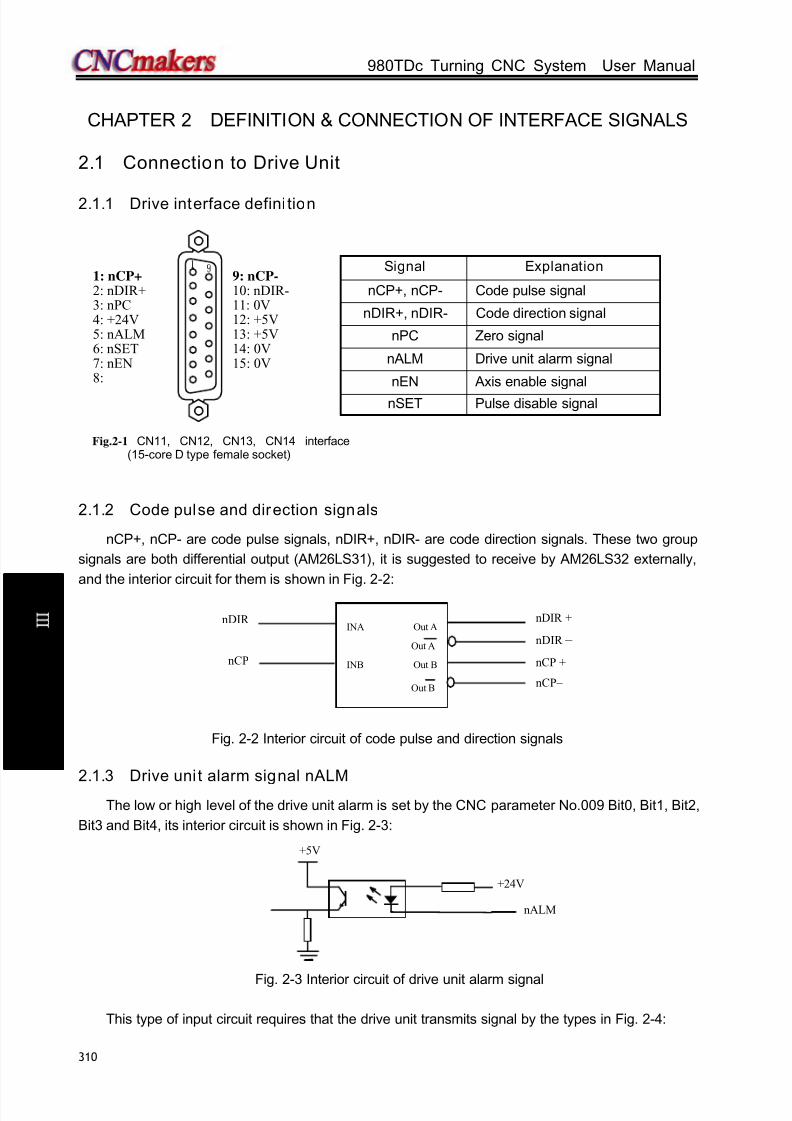
8/17/2019 980TDc CNC Turning Controller User Manual
http://slidepdf.com/reader/full/980tdc-cnc-turning-controller-user-manual 325/461
GSK980TDc Turning CNC System User Manual
310
C onn e c t i on
CHAPTER 2 DEFINITION & CONNECTION OF INTERFACE SIGNALS
2.1 Connection to Drive Unit
2.1.1 Drive interface defini tion
2.1.2 Code pulse and direction signals
nCP+, nCP- are code pulse signals, nDIR+, nDIR- are code direction signals. These two group
signals are both differential output (AM26LS31), it is suggested to receive by AM26LS32 externally,
and the interior circuit for them is shown in Fig. 2-2:
Fig. 2-2 Interior circuit of code pulse and direction signals
2.1.3 Drive unit alarm signal nALM
The low or high level of the drive unit alarm is set by the CNC parameter No.009 Bit0, Bit1, Bit2,
Bit3 and Bit4, its interior circuit is shown in Fig. 2-3:
Fig. 2-3 Interior circuit of drive unit alarm signal
This type of input circuit requires that the drive unit transmits signal by the types in Fig. 2-4:
Signal Explanation
nCP+, nCP- Code pulse signal
nDIR+, nDIR- Code direction signal
nPC Zero signal
nALM Drive unit alarm signal
nEN Axis enable signal
nSET Pulse disable signal
1: nCP+ 2: nDIR+3: nPC4: +24V5: nALM6: nSET7: nEN8:
9: nCP-
10: nDIR-11: 0V12: +5V13: +5V14: 0V15: 0V
Fig.2-1 CN11, CN12, CN13, CN14 interface(15-core D type female socket)
+5V
nALM
+24V
INA Out A
Out A
INB Out B
Out B
nDIR +
nDIR –
nCP +
nCP–
nDIR
nCP
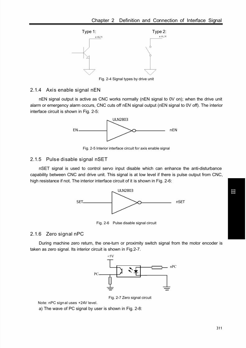
8/17/2019 980TDc CNC Turning Controller User Manual
http://slidepdf.com/reader/full/980tdc-cnc-turning-controller-user-manual 326/461
Chapter 2 Definition and Connection of Interface Signal
311
C onn e c t i on
Type 1: Type 2:
Fig. 2-4 Signal types by drive unit
2.1.4 Axis enable signal nEN
nEN signal output is active as CNC works normally (nEN signal to 0V on); when the drive unit
alarm or emergency alarm occurs, CNC cuts off nEN signal output (nEN signal to 0V off). The interior
interface circuit is shown in Fig. 2-5:
Fig. 2-5 Interior interface circuit for axis enable signal
2.1.5 Pulse disable signal nSET
nSET signal is used to control servo input disable which can enhance the anti-disturbance
capability between CNC and drive unit. This signal is at low level if there is pulse output from CNC,
high resistance if not. The interior interface circuit of it is shown in Fig. 2-6:
Fig. 2-6 Pulse disable signal circuit
2.1.6 Zero signal nPC
During machine zero return, the one-turn or proximity switch signal from the motor encoder istaken as zero signal. Its interior circuit is shown in Fig.2-7.
Fig. 2-7 Zero signal circuit
Note: nPC signal uses +24V level.
a) The wave of PC signal by user is shown in Fig. 2-8:
EN
ULN2803
nEN
SET
ULN2803
nSET
+5V
PC
nPC

8/17/2019 980TDc CNC Turning Controller User Manual
http://slidepdf.com/reader/full/980tdc-cnc-turning-controller-user-manual 327/461
GSK980TDc Turning CNC System User Manual
312
C onn e c t i on
Fig. 2-8 PC signal wave
Note: During the machine zero return, the CNC detects the jumping of the PC signal to judge the reference
point after the DEC switch is detached, which is active in both rise edge and trailing edge of the wave.
b) The wiring of NPN Hall element taken as both DEC signal and zero signal is shown in Fig. 2-9:
Fig. 2-9 Wiring by a NPN Hall element
c) The wiring of PNP Hall elements taken as both DEC signal and zero signal is shown in Fig.
2-10:
Fig. 2-10 Wiring by a PNP Hall element
NPN Hall element
DECn
nPC
PNP型霍尔元件 +24V
PNP Hall element
nDEC
nDEC
nPC
+24V

8/17/2019 980TDc CNC Turning Controller User Manual
http://slidepdf.com/reader/full/980tdc-cnc-turning-controller-user-manual 328/461
Chapter 2 Definition and Connection of Interface Signal
313
C onn e c t i on
2.1.7 Connection to a drive unit
GSK 980TDc/GSK980TDc-V is connected with our drive unit, shown in Fig. 2-11:
980TDc side(CN11,CN12, CN13, CN14)
GS2000T-N side CN1
nCP+ 1 2 PULS+
nCP - 9 17 PULS -
n DIR+ 2 1 SIGN+
nDIR - 10 16 SIGN -
n ALM 5 9 ALM+
nPC 3 29 ZOUT-
0V 14 23 SON
0V 11 24 COM- 25 ALM -
+24V 4 39 COM+
13 ZOUT+
Metal shell
Metal shell
Con nect ion betw een GSK980TDc and GS2000T-Neconomical servo unit
Note: On 980TDc side, interfaces CN11, CN12, CN13, CN14 adapts 2-stripe male plug; while on
GS2000T-N side, CN1 adapts DB44 3-stripe male plug;
Metal shell
GSK980TDc(CN11,CN12,CN13,CN14)
Connection between GSK980TDc and DA98 (A)
+
DA98(A)signalinterface
Metal shell
15
29
30
DA98B signalinterface
PULS+
SIGN+PULS-
ALM
SON36
23
5
CZ+COM+38
3732 DG
CZ-
14 SIGN-
nCP-nCP+
nDIR+
nPCnALM
+240V
10 nDIR-
Connection between GSK980TDc and DA98B
GSK980TDc(CN11,CN12,CN13,CN14)
Metal shell Metal shell

8/17/2019 980TDc CNC Turning Controller User Manual
http://slidepdf.com/reader/full/980tdc-cnc-turning-controller-user-manual 329/461
GSK980TDc Turning CNC System User Manual
314
C onn e c t i on
Connect ion b etween GSK980TDc and DY3
Metal shell
GSK980TDc(CN11, CN12,CN13,CN14)
DY3 signal interface
Metal shell
Connection between GSK980TDc and DF3
GSK980TDc(CN11, CN12,CN13,CN14)
Metal shell
DF3 signal interface
Metal shell
Fig. 2-11 GSK 980TDc/GSK980TDc-V CNC systems are connected with GSK drive unit
2.2 Being Connected with Spindle Encoder
2.2.1 Spindle encoder interface defini tion
2.2.2 Signal explanation
*PCS/PCS,*PBS/PBS,*PAS/PAS are the encoder C, B, A phases differential input signals
respectively, which are received by 26LS32; *PAS/PAS,*PBS/PBS are orthogonal square wave with
phase shift 90°and their maximum signal frequency is less than 1MHz; the encoder pulses for
GSK980TDc are set at will by parameter, the setting range is from 100 to 5000.
Its interior circuit is shown in Fig. 2-13: (n=A, B, C)
Fig. 2-13 Encoder signal circuit
2.2.3 Being connected with spindle encoder interface
GSK980TDc/GSK980TDc-V is connected with spindle encoder shown in Fig. 2-14, and it usestwisted pair cables. (exemplified by CHANGCHUN YIGUANG ZLF-12-102.4BM-C05D encoder):
Fig.2-12 CN21 encoder interface(15-core D type male socket)
8: PAS 7: *PAS6: PBS5: *PBS4: PCS3: *PCS
15: 0V 14: 0V13: +5V12: 5V11: 0V
PnS
*PnS
AM26LS32
Name Explanation
*PAS/PAS Encoder A phase pulse*PBS/PBS Encoder B phase pulse*PCS/PCS Encoder C phase pulse

8/17/2019 980TDc CNC Turning Controller User Manual
http://slidepdf.com/reader/full/980tdc-cnc-turning-controller-user-manual 330/461
Chapter 2 Definition and Connection of Interface Signal
315
C onn e c t i on
Fig. 2-14 GSK980TDc/GSK980TDc-V is connected with the encoder
2.3 Being Connected with MPG (Manual Pulse Generator)
2.3.1 MPG interface defini tion
Fig. 2-15 CN31 MPG interface
(26-core DB type male socket)
Signal ExplanationHA+,HA- MPG A phase signalHB+,HB- MPG B phase signal
+24VDC power supply
+5V,0V
Standard PLC Definition Address Funct ion
X6.0 X MPG axis selectionX6.1 Y MPG axis selectionX6.2 Z MPG axis selectionX6.3 increment×1X6.4 increment×10X6.5 increment×100
2.3.2 Signal explanation
HA,HB are the MPG A, B phase input signals respectively. Their interior circuit is shown in Fig.
2-16:
XHA-
470RR93
XHB-
470RR96
R98
1K
R94
1K
U57
TLP181
1
2
4
3
D49
1N4148
D47
1N4148
VCC
VCC
GND
GND
U55
TLP181
1
2
4
3
XHB+
XHA+
Fig. 2-16 MPG signal circuit
GSK980TDc/GSK980TDc-V is connected with MPG shown in Fig. 2-17:
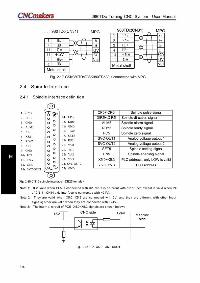
8/17/2019 980TDc CNC Turning Controller User Manual
http://slidepdf.com/reader/full/980tdc-cnc-turning-controller-user-manual 331/461
GSK980TDc Turning CNC System User Manual
316
C onn e c t i on
1114
3 HB+HA+
+5V
HA-HB-
24
Metal shell
GSK980TDc(CN31) MPG
Null
B-
B+A-
4
2
HB-
HA-
Null
HB+3
1411
Metal shell
GSK980TDc(CN31)
HA+ A+
MPG
Fig. 2-17 GSK980TDc/GSK980TDc-V is connected with MPG
2.4 Spindle Interface
2.4.1 Spindle interface defini tion
Note 1: It is valid when PC5 is connected with 0V, and it is dif ferent with other feed axes(it is valid when PC
of CN11~CN14 axis interface is connected with +24V).
Note 2: They are valid when X5.0~
X5.3 are connected with 0V, and they are different with other inputsignals( other are valid when they are connected with +24V).
Note 3: The internal circuit of PC5,X5.0~X5.3 signals are shown below :
Fig. 2-19 PC5, X5.0~X5.3 circuit
CP5+,CP5- Spindle pulse signal
DIR5+,DIR5- Spindle direction signal
ALM5 Spindle alarm signal
RDY5 Spindle ready signal
PC5 Spindle zero signal
SVC-OUT1 Analog voltage output 1
SVC-OUT2 Analog voltage output 2
SET5 Spindle setting signalEN5 Spindle enabling signal
X5.0~X5.3 PLC address,only LOW is valid
Y5.0~Y5.3 PLC address
Fig. 2-18 CN15 spindle interface(DB25 female)
1:CP5+
2:DIR5+
3:GND
4:ALM5
5:X5.0
6:X5.1
7:RDY5
8:X5.2
9:GND
10:PC5
11:+24V
12:GND
13:SVC-OUT1
14:CP5-
15:DIR5-
16:GND
17:+24V
18:SET5
19:EN5
20:Y5.0
21:Y5.1
22:Y5.2
23:Y5.3
24:SVC-OUT2
25:GND

8/17/2019 980TDc CNC Turning Controller User Manual
http://slidepdf.com/reader/full/980tdc-cnc-turning-controller-user-manual 332/461
Chapter 2 Definition and Connection of Interface Signal
317
C onn e c t i on
2.4.2 Connection to inverter
The analog spindle interface SVC may output 0~10V voltage, its interior signal circuit is shown in
Fig. 2-20:
Fig. 2-20 SVC signal circuit
GSK980TDc is connected with the inverter shown in Fig. 2-21:
Fig. 2-21 GSK980TDc/GSK980TDc-V is connected with the inverter
2.5 GSK980TDc/GSK980TDc-V being Connected with PC
2.5.1 Communication interface definition
Fig. 2-22 CN51 communication interface (DB9-female)
2.5.2 Communication interface connection
GSK980TDc/GSK980TDc-V can perform the communication by CN51 and PC(optional
communication software). GSK980TDc/GSK980TDc-V is connected with PC shown in Fig 2-23A:
GSK980TDc(CN51)
Metal shell
RS232 interface on PC
Metal shell
Fig. 2-23A GSK980TDc is connected with PC
Signal Explanation
RXD Receiving data
TXD Transmitting data
GND Signal grounding
6: 7:8:9:
1: 2: RXD3: TXD4:5: GND
SVC

8/17/2019 980TDc CNC Turning Controller User Manual
http://slidepdf.com/reader/full/980tdc-cnc-turning-controller-user-manual 333/461
GSK980TDc Turning CNC System User Manual
318
C onn e c t i on
2.6 Power Interface Connection
GSK-PB2 power box is applied in GSK980TDc system, which involves 4 groups of voltage:
+5V(3A) ,+12V(1A) ,-12V(0.5A) ,+24V(0.5A) , and its common terminal is COM(0V) . The connection
of GSK-PB2 power box to GSK980TDc XS2 interface has been done for its delivery from factory, and
the user only need to connect it to a 220V AC power in using.
+5 V
+5 V
0V
+5 V
+12V0V
-12V0V+24V
Fig. 2-24 system power interface CN1
2.7 I/O Interface Definit ion
Note!The I/O function significances of the unlabelled fixed addresses of
this GSK980TDb/GSK980TDb-V turning machine CNC system aredefined by PLC programs (ladders), and they are defined by themachine builder when matching with a machine, please refer to themanual by the machine builder.
The fixed address I/O function not be marked are described for
GSK980TDb PLC. The described contents without other specialexplanation are also applied to GSK980TDb-V.

8/17/2019 980TDc CNC Turning Controller User Manual
http://slidepdf.com/reader/full/980tdc-cnc-turning-controller-user-manual 334/461
Chapter 2 Definition and Connection of Interface Signal
319
C onn e c t i on
Fig.2-25 input
interface(CN61)
Pin Address Function Explanation
21~24 0V Power supply
interface
17~20
25~28Floating Floating Floating
1 X0.0 SAGT Guard door check signal
2 X0.1 SP External feed hold signal
3 X0.2 DIQP Chuck input signal
4 X0.3 DECX(DEC1) X deceleration signal
5 X0.4 DITW Tailstock control signal
6 X0.5 ESP External emergency stop signal
7 X0.6 PRES Pressure check signal
8 X0.7 T05 Tool signal /OV1
9 X1.0 T06/ strobe Tool signal /OV2/strobe signal
10X1.1
T07/
pregraduation
Tool signal /OV3/pregraducation
proximity switch
11
X1.2
T08/ tool post
worktable
overheat
Tool signal/OV4/ tool worktable
overheat check
12 X1.3 DECZ(DEC3) Z deceleration signal
13 X1.4 ST External cycle start signal
14 X1.5 M41I Shifting gear to 1s gear in-position
15 X1.6 M42I Shifting gear to 2n
gear in-position
16 X1.7 T01 Tool signal
29 X2.0 T02 Tool signal
30 X2.1 T03 Tool signal
31 X2.2 T04 Tool signal
32 X2.3 DECY(DEC2) Y deceleration signal33 X2.4 DEC4 4 deceleration signal
34 X2.5 DEC5 5 deceleration signal
35 X2.6 TCP Tool post clamping signal
36 X2.7 AEY/BDT External skip
37 X3.0 LMIX X overtravel
38 X3.1 LMIY Y overtravel
39 X3.2 LMIZ Z overtravel
40X3.3
WQPJ
Inner chuck releasing/outer chuck
clamping in-position signal
41X3.4
NQPJ
Inner chuck clamping/outré chuck
releasing in-position signal42 X3.5 SKIP G31 skip signal
43X3.6
AEX X tool measure position arrival
signal (G36)
44X3.7
AEZ Z tool measure position arrival
signal(G37)

8/17/2019 980TDc CNC Turning Controller User Manual
http://slidepdf.com/reader/full/980tdc-cnc-turning-controller-user-manual 335/461
GSK980TDc Turning CNC System User Manual
320
C onn e c t i on
Fig.2-26 output interface
(CN62)
Note 1: Various functions can be defined to some of the input and outpu t interfaces, and they are indicatedby “ /” sign in the table above.
Note 2: If output function is active, the output signal is through on to 0V. If output funct ion is inactive, the
output signal is cut off by high impedance.
Note 3: If input function is active, the input signal is through on to +24V. If input function is inactive, the
input signal is cut off with i t.
Note 4: The effecti veness of +24V, COM terminals are equivalent to those of the GSK980TDc/GSK980TDc
power box terminals that have the same names.
2.7.1 Input signal
Input signal means the signal from machine to CNC, when this signal is through on with +24V,
the input is active; when it is off with +24V, the input is inactive. The contact of input signal at machine
side should meet the following conditions:
Pin Address Function Explanation
17,18,19,
26,27,280V
Power supply
interfacePower supply 0V terminal
20~25 +24V Power supply
interfacePower supply +24V terminal
1 Y0.0 M08 Cooling output
2 Y0.1 M32 Lubricating output
3 Y0.2 Reserved
4 Y0.3 M03 Spindle rotation (CCW)
5 Y0.4 M04 Spindle rotation (CW)
6 Y0.5 M05 Spindle stop
7 Y0.6 reserved
8 Y0.7 SPZD Spindle brake
9 Y1.0 S1/M41 Spindle machine gear output 1
10 Y1.1 S2/M42 Spindle machine gear output 2
11 Y1.2 S3/M43 Spindle machine gear output 312 Y1.3 S4/M44 Spindle machine gear output 4
13 Y1.4 DOQPJ(M12) Chuck clamping output
14 Y1.5 DOQPS(M13) Chuck releasing output
15 Y1.6 TL+ Tool post CCW rotation
16 Y1.7 TL- Tool post CW rotation
29 Y2.0 TZD Tool post worktable brake
30 Y2.1 INDXS Tool post worktable graduation coil
31 Y2.2 YLAMP Three-color lamp-yellow
32 Y2.3 GLAMP Three-color lamp -green
33 Y2.4 RLAMP Three-color lamp -red
34 Y2.5 DOTWJ(M10) Tailstock forward35 Y2.6 DOTWS(M11) Tailstock backward
36 Y2.7 reserved
37 Y3.0 reserved
38 Y3.1 reserved
39 Y3.2 UO0 User macro output 0
40 Y3.3 UO1 User macro output 1
41 Y3.4 UO2 User macro output 2
42 Y3.5 UO3 User macro output 3
43 Y3.6 UO4 User macro output 4
44 Y3.7 UO5 User macro output 5

8/17/2019 980TDc CNC Turning Controller User Manual
http://slidepdf.com/reader/full/980tdc-cnc-turning-controller-user-manual 336/461
Chapter 2 Definition and Connection of Interface Signal
321
C onn e c t i on
Capacity of the contact: DC30V, 16mA above
Leakage current between contacts in open circuit: 1mA below
Voltage drop between contacts in closed circuit: 2V below (current 8.5mA, including cable
voltage drop)
There are two external input types for input signals: one type is input by contact switch whose
signals are from keys, stroke switch and contacts of relay at machine side, as shown in Fig. 2-27:
Fig. 2-27
The other type is input by switch with no contacts (transistor) as shown in Fig. 2-28A, 2-28B:
Fig. 2-28A NPN connection
Fig. 2-28B PNP connection
The input interface signals defined by PLC of GSK980TDc/GSK980TDc-V system involve
XDEC, ZDEC, ESP, ST, SP/SAGT, PRES, DITW, DIQP, T01~T08, TCP and so on.
2.7.2 Output signal
The output signal is used for the machine relay and indicator, if it is through on with 0V, the
output function is active; if it is off with 0V, the output function is inactive. There are 36 digital volume
outputs that they all have the same structure in I/O interface as shown in Fig. 2-29:

8/17/2019 980TDc CNC Turning Controller User Manual
http://slidepdf.com/reader/full/980tdc-cnc-turning-controller-user-manual 337/461
GSK980TDc Turning CNC System User Manual
322
C onn e c t i on
Fig. 2-29 Circuit for digital volume output module
The logic signal OUTx output from the main board is sent to the input terminal of inverter
(ULN2803) via a connector. And there are 2 types for nOUTx output: 0V, or high impedance. Its
typical application is as follows:
To drive LED
A serial resistance is needed to limit the current (usually 10mA) that goes through the LED by
using ULN2803 output to drive LED, which is shown in Fig. 2-30:
Fig. 2-30
To drive filament indicator
An external preheat resistance is needed to decrease the current impact at power on by using
ULN2803 output to drive filament indicator, and this resistance value should be within a range that the
indicator cannot be lighted up as shown in Fig. 2-31:
+24VCNC side Machineside
ULN2803output
+24VMachineside
CNC side
RelayULN2803
output
Fig. 2-31 Fig.2-32
To drive inductive load (such as relay)
To use ULN2803 output to drive an inductive load, it requires to connect a freewheeling diode
near the coil to protect output circuit and reduce interference as shown in Fig. 2-32:
The significances of the output signal of I/O interface are defined by PLC program, these signals
include S1~S4 (M41~M44), M3, M4, M5, M8, M10, M11, M32, TL-, TL+, U00~U05, DOQPJ,
DOQPS, SPZD signals etc.. And their common terminal is +24V.

8/17/2019 980TDc CNC Turning Controller User Manual
http://slidepdf.com/reader/full/980tdc-cnc-turning-controller-user-manual 338/461
Chapter 2 Definition and Connection of Interface Signal
323
C onn e c t i on
2.8 I/O Function and Connection
2.8.1 Stroke limit and emergency stop
Relevant signal
ESP: emergency stop signal, alarm issued if the system is not connected with +24V
LMIX: X overtravel limit check input
LMIY: Y overtravel limit check input
LMIZ: Z overtravel limit check input
Diagnosis data
0 0 0 ESP
Pin CN61.6
Signal diagnosisSignal ESP LMIX LMIY LMIZ
Diagnosis address X0.5 X3.0 X3.1 X3.2
Interface pin CN61.6 CN61.37 CN61.38 CN61.39
Control parameter
Bit parameter
1 7 2 ESP
ESP =0: Check ESP signal
=1: Do not check ESP signal
PLC bit parameter
K 1 0 LMIT LMIS
LMIT =1: Travel limit check function of each axis is valid.=0: Travel limit check function of each axis is invalid
LMIS =1: The system alarms for overtravel when the travel limit check signal is not connected
with +24V.
=0: The system alarms for overtravel when the travel limit check signal is connected with
+24V
Signal connection
The ESP signal circuit is shown in Fig.2-33:
Note! The I/O function significance of this GSK980TDb/GSK980TDb-V turning
machine CNC system is defined by PLC programs (ladders), and they are defined bythe machine builder when matching with a machine, please refer to the manual bythe machine builder.
The fixed address I/O function not be marked are described for GSK980TDbPLC. The described contents without other special explanation are also applied toGSK980TDb-V.

8/17/2019 980TDc CNC Turning Controller User Manual
http://slidepdf.com/reader/full/980tdc-cnc-turning-controller-user-manual 339/461
GSK980TDc Turning CNC System User Manual
324
C onn e c t i on
Fig. 2-33 ESP signal circuit
Machine external connection
(1) The series connection between the emergency stop and travel switch is shown in Fig. 2-34A:
Fig.2-34A Series connection between emergency stop and travel switch
(2) The separate connection between the emergency stop and travel switch is shown in Fig.
2-34B:
Fig. 2-34B Separate connection between the emergency stop and travel switch
Control logic
(1) Series connection between the emergency stop and travel switch
When the contact of the emergency stop switch is cut off, the ESP signal is off to +24V, and CNC
makes an emergency alarm. Meanwhile the CNC turns off the enable (EN) signal to stop the pulse
output. Except the functions processed by NC, other functions can also be defined by PLC program
when the emergency alarm is issued. The function defined by standard PLC program is: when
emergency alarm is issued, it turns off the signal output of M03, M04, M08, and outputs M05 signal at
the same time.
(2) Separate connection between the emergency stop and travel switch
1. Each axis has only one overtravel contact, and the system judges the overtravel alarm
based on the axis movement direction.
2. When the system alarms for the overtravel, the axis moves reversely, the reset key is
pressed to clear the alarm after the axis exceeds the limit position.Note: Before the overtravel limit function is enabled, the slider must be between the positive and the negative
limit; o therwise, the prompted alarm will not be consistent wi th actual situation.

8/17/2019 980TDc CNC Turning Controller User Manual
http://slidepdf.com/reader/full/980tdc-cnc-turning-controller-user-manual 340/461
Chapter 2 Definition and Connection of Interface Signal
325
C onn e c t i on
2.8.2 Tool change control
Relevant signals (by standard PLC program)
Signal
type
Code Interface Address Function Remark
Input
signal
T01 CN61.16 X1.7 Tool signal 1/Sensor A(Liuxin Tool Post)
T02 CN61.29 X2.0 Tool signal 2/Sensor B(Liuxin Tool Post)
T03 CN61.30 X2.1 Tool signal 3/Sensor C(Liuxin Tool Post)
T04 CN61.31 X2.2 Tool signal 4/Sensor D(Liuxin Tool Post)
T05 CN61.08 X0.7 Tool signal 5/Sensor E(Liuxin Tool Post) Also as
OV1 input
T06 CN61.09 X1.0Tool signal 6/strobe signal(Yantai AK31)
/Sensor F(Liuxin Tool Post)
Also as
OV2 input
T07 CN61.10 X1.1Tool signal7/pre-graduation proximity switch
(Yantai AK31)
Also as
OV3 input
T08 CN61.11 X1.2Tool signal8/tool post worktable overheat
check(Yantai AK31)
Also as
OV4 input
TCP CN61.35 X2.6 Tool post locking signal
Output
signal
TL+ CN62.15 Y1.6 Tool post rotation(CW) signal
TL- CN62.16 Y1.7 Tool post rotation(CCW) signal
TZD/TLS CN62.29 Y2.0Tool post worktabke brake(Yantai AK31)/
tool pot releasing(Liuxin Tool Post) INDXS/
TCLPCN62.30 Y2.1
Tool post worktable pregraduation coil(Yantai
AK31)/tool pot lock(Liuxin Tool Post)
Control parameter
Bit parameter
K 1 1 CHOT CHET TCPS CTCP TSGN CHTB CHTA
CHTA: tool change mode selection bit 0
CHTB: tool change mode selection bit 1(see following table)
TSGN =0 : tool signal HIGH(turn on +24V) is valid
=1 : tool signal LOW(turn off +24V) is valid
CTCP =0 : do not check tool post locking signal
=1 : check tool post locking signal
TCPS =0 : tool post locking signal LOW(turn off +24V) is valid
=1 : tool post locking signal HIGH(turn on +24V) is valid
CHET=0 : do not check tool signal after the tool change is completed
CHTB CHT A Tool post type0 0 Standard tool change mode B
0 1 Standard tool change mode A
1 0 Yantai AK31
1 1 Unused
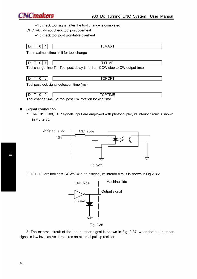
8/17/2019 980TDc CNC Turning Controller User Manual
http://slidepdf.com/reader/full/980tdc-cnc-turning-controller-user-manual 341/461
GSK980TDc Turning CNC System User Manual
326
C onn e c t i on
=1 : check tool signal after the tool change is completed
CHOT=0 : do not check tool post overheat
=1 : check tool post worktable overheat
D T 0 4 TLMAXT
The maximum time limit for tool change
D T 0 7 T1TIME
Tool change time T1: Tool post delay time from CCW stop to CW output (ms)
D T 0 8 TCPCKT
Tool post lock signal detection time (ms)
D T 0 9 TCPTIME
Tool change time T2: tool post CW rotation locking time
Signal connection
1. The T01~T08, TCP signals input are employed with photocoupler, its interior circuit is shown
in Fig. 2-35:
Fig. 2-35
2. TL+, TL- are tool post CCW/CW output signal, its interior circuit is shown in Fig.2-36:
Fig. 2-36
3. The external circuit of the tool number signal is shown in Fig. 2-37, when the tool number
signal is low level active, it requires an external pull-up resistor.
+24V
ULN2803
TL+/TL-
CNC侧CNC side
Output signal
Machine side

8/17/2019 980TDc CNC Turning Controller User Manual
http://slidepdf.com/reader/full/980tdc-cnc-turning-controller-user-manual 342/461
Chapter 2 Definition and Connection of Interface Signal
327
C onn e c t i on
·
Fig. 2-37
Function description (defined by standard PLC program)
The control sequence and control logic of the tool change are defined by PLC program. There
are 4 tool change modes defined as follows by standard PLC program:
1. CHTB (K11.1)=0, CHTA (K11.0)=0: tool change mode B
①During the tool change process, CNC outputs TL+ signal until the tool in-position signal is
detected, then CNC turns off TL+ signal output and outputs TL- signal after a delay time
specified by data parameter No.082. Then CNC detects TCP signal till it is detected, the CNC
turns off TL- signal after a delay time specified by the data parameter No.085. So the tool change
is over.
②When CHET(K0011.5) is set to 1(check tool signal after the tool change ends) and the tool
post (CCW) rotation time ends to confirm whether the current tool input signal is consistent with
the current tool No., if not, the system alarms.
③ The tool change process ends.
④ After the system outputs the tool post rotation(CCW)signal, if the CNC doesn’t receive the
TCP signal within the time set by DT08, an alarm will be issued and the TL- signal will be turnedoff.
⑤ When the tool post has no tool post locking signal, CTCP(K0011.3) is set to 0, at the time,
the system does not check the tool post locking signal.
or
Sequence of tool change mode B
2. CHTB (K11.1)=0,CHTA (K11.0)=1: tool change mode A:
① After the tool change is executed, the system outputs the tool rotation(CW)signal TL+ and
checks the tool in-position signal, and then after it has checked the tool signal and closes TL+,
last checks whether the tool signal skips, if done, it outputs the tool rotation (CCW) signal TL-.
Then, the system checks the locking signal TCP, it delays the time set by DT09 and closes
TL- after it has received the TCP;② When CHET(K0011.5)is set to 1(check tool signal after the tool change ends),the system
confirms whether the current tool input signal is consistent with the current tool number after the
CNC side Machine side
Hall switch

8/17/2019 980TDc CNC Turning Controller User Manual
http://slidepdf.com/reader/full/980tdc-cnc-turning-controller-user-manual 343/461
GSK980TDc Turning CNC System User Manual
328
C onn e c t i on
tool post (CCW) rotation time ends, if not, the system alarms;
③ The tool change process ends.
④ After the system outputs the too rotation(CCW) signal, when it has not received TCP signal in
the time set by DT08, it alarms and closes TCP signal.
⑤ If the tool post has no locking signal, CTCP(K0011.3)is set to 0,at the time, the system does
not check the tool post locking signal.
or
Sequence of tool change mode A
Note 1: DT07 setting is invalid , the system does not check in the delay time between the tool post (CW)stop
and the tool post (CCW) rotation locked.
Note 2: Except for DT07, relative parameter setting and function of other tool post cont rol are valid.
3.CHTB=1,CHTA =0 : Yantai AK31 series (6, 8, 10, 12 tools) Chanzhou SBWD-80
a). Tool change process
⑴. Ensure the tool post brake TZD signal is turned on.
⑵.The system executes the shortest path judge based on the target tool no. and the current tool
no., and selects the rotation direction of the output according to the nearby tool selection, outputs the
positive signal(TL+) or negative signal (TL-), and the tool post rotates to select the tool.⑶.During the rotation, the system decodes to identify the current tool no. based on the tool
encoding signal T1~T4 input. When it rotates to the previous tool before the target tool no,. it checks
the skip of the tool post strobe signal. The strobe signal of the previous signal before the target tool no.
executes the falling edge, the system outputs pregraduation electromagnetic signal of the tool post,
and the electromagnet is turned on.
⑷.When the input signal of the pregraduation proximity input signal of the tool post is HIGH, the
system closes the tool post rotation output signal (TL+ or TL-), and the motor stops.
⑸.After the system delays 50ms, it outputs the signal(TL- or TL+) which is reverse to the
previous rotation direction and the tool post rotates reversely.⑹.When the proximity input signal of the tool post locked is HIGH, the system closes the rotation
signal(TL-, TL+), and the motor stops. Then the system outputs the tool post brake signal TZD, and
the motor brake is turned on.
⑺.When the system delays 200ms,it closes the pregraduation electromagnetic output signal,
and then the electromagnet is turned off.
⑻.The system checks the current tool no. again and confirms whether the encoding signal of the
current tool is consistent with the target tool no..
⑼.The system confirms again whether the locked proximity switch signal is HIGH.
⑽.When the above steps are correct, the system closes the tool post brake signal TZD, and so
the tool change is completed.
⑾.In the course of the tool change, when the system has found the motor overheat signal, it

8/17/2019 980TDc CNC Turning Controller User Manual
http://slidepdf.com/reader/full/980tdc-cnc-turning-controller-user-manual 344/461
Chapter 2 Definition and Connection of Interface Signal
329
C onn e c t i on
alarms and closes output of all signals.
b). Tool change flow

8/17/2019 980TDc CNC Turning Controller User Manual
http://slidepdf.com/reader/full/980tdc-cnc-turning-controller-user-manual 345/461
GSK980TDc Turning CNC System User Manual
330
C onn e c t i on
4. CHTB (K11.1)=1,CHTA(K11.0)=1: Liuxin hydraulic tool post
4.1 . Corresponding table between position and signal
8-tool:
1 2 3 4 5 6 7 8
A
B
C
D
E
10-tool:
1 2 3 4 5 6 7 8 9 10
A
B
C
D
E
12-tool:
1 2 3 4 5 6 7 8 9 10 11 12
A
B
C
D
E
4.2 Signal specification
Sensor A, B, C, D: only check the tool, and are not any start signals
Sensor E: it executes the inductive once when one tool change is executed, which makes the
tool pot stop and the start signal be locked. When the tool pot rotates to the required
position, Sensor is inductive, i.e. the electromagnet to control the tool pot rotation is
turned off, which makes the tool stop rotation and start the electromagnet to lock the
tool pot to ensure that the tool pot is locked.
Sensor F: releasing/lock confirmation signal. When it is not inductive, the tool pot is released, at
the time, the tool pot is started to rotate. When it is not inductive, the tool pot is locked,
i.e. the tool change is completed.
Sol A: control the tool pot releasing/locking
Sol B: control the tool pot rotation(CW/CCW)
4.3 Tool change process description
Example: No. 1 tool is changed into No. 4 tool
Step 1: Sol A is turned on(tool pot is released)
Step 2: Ensure Sensor F is not inductive, Sol B is turned and the oil hydraulic motor rotates
Step 3: check the tool signal(Note: Sensor E is inductive for No. 1, 2, 3 tool, does not execute the
locking operation when the tool pot does not reach No. 4 tool). When No. 3 tool signal is confirmed,
Sensor E preparatory operation should be set to make the tool pot rotate to No.4 tool, at the time,
Sensor E is inductive, i.e. Sol B is turned on, the tool pot stops rotation and Sol A makes the tool potbe locked.

8/17/2019 980TDc CNC Turning Controller User Manual
http://slidepdf.com/reader/full/980tdc-cnc-turning-controller-user-manual 346/461
Chapter 2 Definition and Connection of Interface Signal
331
C onn e c t i on
2.8.3 Machine zero return
Relative signal
DECX: X deceleration signal;
DECY: Y deceleration signal;
DECZ: Z deceleration signal;
DEC4: 4th deceleration signal;
DEC5: 5th deceleration signal;
PCX: X zero signal;
PCY: Y zero signal;
PCZ: Z zero signal;
PC4: 4th zero signal;
PC5: 5th zero signal;
Diagnosis data
0 0 0 DEC5 DEC4 DECZ DECY DECX
Interface pin CN61.34 CN61.33 CN61.12 CN61.32 CN61.4
0 0 8 PC5 PC4 PCY PCZ PCX
Interface pin CN15.10 CN14.3 CN13.3 CN12.3 CN11.3
Controlling parameter
Status parameters0 0 4 DECI
Bit 5 1: During machine zero return, the deceleration signal is at high level;
0: During machine zero return, the deceleration signal is at low level;
0 0 5 PPD
Bit 1: 1: G50 sets relative coordinate system value;0: G50 does not set relative coordinate system value;
0 0 6 ZM5 ZM4 ZMY ZMZ ZMX
Bit4 1: 5th axis zero point return method C0: 5th axis zero point return method B
Bit3 1: 4th axis zero point return method C0: 4th axis zero point return method B
Bit2 1:Y axis zero point return method C0:Y axis zero point return method B
Bit1 1:Y axis zero point return method C0:Y axis zero point return method B
Bit0 1:X axis zero point return method C0:X axis zero point return method B
0 0 7 ZC5 ZC4 ZCY ZCZ ZCX
Bit 4 1: During machine zero return, the deceleration signal of the 5th axis (DEC5) and one-rotation
signal (PC5) are connected in parallel (use a proximity switch as a deceleration signal and
zero-point signal at the same time).
0: During machine zero return, the deceleration signal of the 5
th
axis (DEC5) and one-rotationsignal (PC5) are connected separately (use a proximity switch as a deceleration signal
and zero-point signal at the same time).

8/17/2019 980TDc CNC Turning Controller User Manual
http://slidepdf.com/reader/full/980tdc-cnc-turning-controller-user-manual 347/461
GSK980TDc Turning CNC System User Manual
332
C onn e c t i on
Bit 3 1: During machine zero return, the deceleration signal of the 4th axis (DEC4) and one-rotation
signal (PC4) are connected in parallel (use a proximity switch as a deceleration signal and
zero-point signal at the same time).
0: During machine zero return, the deceleration signal of the 4th axis (DEC4) and
one-rotation signal (PC4) are connected separately (use a proximity switch as a
deceleration signal and zero-point signal at the same time).
Bit 2 1: During machine zero return, the deceleration signal of the Y axis (DECY) and one-rotation
signal (PCY) are connected in parallel (use a proximity switch as a deceleration signal and
zero-point signal at the same time).
0: During machine zero return, the deceleration signal of the Y axis (DECY) and one-rotation
signal (PCY) are connected separately (use a proximity switch as a deceleration signal
and zero-point signal at the same time).
Bit 1 1: During machine zero return, the deceleration signal of the Z axis (DECZ) and one-rotation
signal (PCZ) are connected in parallel (use a proximity switch as a deceleration signal and
zero-point signal at the same time).0: During machine zero return, the deceleration signal of the Z axis (DECZ) and
one-rotation signal (PCZ) are connected separately (use a proximity switch as a
deceleration signal and zero-point signal at the same time).
Bit 0 1: During machine zero return, the deceleration signal of the X axis (DECX) and one-rotation
signal (PCX) are connected in parallel (use a proximity switch as a deceleration signal and
zero-point signal at the same time).
0: During machine zero return, the deceleration signal of the X axis (DECX) and one-rotation
signal (PCX) are connected separately (use a proximity switch as a deceleration signal
and zero-point signal at the same time).
0 1 1 NORF ZNLK
Bit3 1: Manual machine zero return is invalid;0: Manual machine zero return is valid;
Bit 2: 1: The direction key is self-locked during machine zero return; press the direction key once tillthe machine zero return is finished;
0: The direction key is not self-locked during machine zero return; press down the direction key;
0 1 2 APRS ISOT
Bit 7 1: CNC sets the absolute coordinate system automatically after reference point return;0: CNC does not set absolute coordinate system automatically after reference point return;
Bit 0 1: Manual rapid traverse is valid after system power-on and before machine zero return;0: Manual rapid traverse is invalid after system power-on and before machine zero return;
0 1 4 ZRS5 ZRS4 ZRSY ZRSZ ZRSX
Bit4, Bit3, Bit2, Bit1, Bit01: Machine zero point is set on the 5th, 4th, Y, Z, X axes; deceleration signal and zero point signal areneeded to be detected during machine zero return;0: Machine zero point is not set on the 5th, 4th, Y, Z, X axes; deceleration signal and zero point signalare not detected during machine zero return;
1 8 3 MZR5 MZR4 MZRY MZRZ MZRX
Bit4/Bit3/Bit2/Bit1/Bit0 1: The direction of machine zero return is negative;0: The direction of machine zero return is positive;

8/17/2019 980TDc CNC Turning Controller User Manual
http://slidepdf.com/reader/full/980tdc-cnc-turning-controller-user-manual 348/461

8/17/2019 980TDc CNC Turning Controller User Manual
http://slidepdf.com/reader/full/980tdc-cnc-turning-controller-user-manual 349/461
GSK980TDc Turning CNC System User Manual
334
C onn e c t i on
Fig. 2-41-a
Return process of machine zero mode B
A: Select Machine zero mode, press the manual positive or negative feed key(machine zero
return direction set by bit parameter No.183), the corresponding axis moves to the
machine zero by a rapid traverse speed. As the axis press down the deceleration switch
to cut off deceleration signal, the feeding slows down immediately, and it continues to run
in a fixed low speed.
B: When the deceleration switch is released, the deceleration signal contact is closed again.
And CNC begins to detect the encoder one-turn signal (PC), if this signal level skips, the
motion will be halted. And the corresponding zero return indicator on the operator panel
lights up for machine zero return completion.
When the BIT0 (ZMX) of the bit parameter No.006 are both set to 1, and the BIT5(DECI) of thebit parameter No.004 is set to 0, it chooses the machine zero return mode C, and the deceleration
signal low level is active.
So the sequence of machine zero return mode C is shown as follows:
Reversely
D e c e l e r a t e s
t o s t o p
Ti me (t)
Return
fini sh
Low return
speed
High return
speed
Vel ocit y (v )
nPC
Zero return speed
Deceleration switch
Fig. 2-41-b
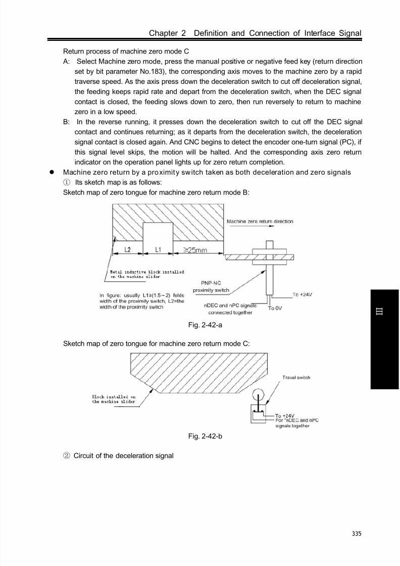
8/17/2019 980TDc CNC Turning Controller User Manual
http://slidepdf.com/reader/full/980tdc-cnc-turning-controller-user-manual 350/461
Chapter 2 Definition and Connection of Interface Signal
335
C onn e c t i on
Return process of machine zero mode C
A: Select Machine zero mode, press the manual positive or negative feed key (return direction
set by bit parameter No.183), the corresponding axis moves to the machine zero by a rapid
traverse speed. As the axis press down the deceleration switch to cut off deceleration signal,
the feeding keeps rapid rate and depart from the deceleration switch, when the DEC signal
contact is closed, the feeding slows down to zero, then run reversely to return to machine
zero in a low speed.
B: In the reverse running, it presses down the deceleration switch to cut off the DEC signal
contact and continues returning; as it departs from the deceleration switch, the deceleration
signal contact is closed again. And CNC begins to detect the encoder one-turn signal (PC), if
this signal level skips, the motion will be halted. And the corresponding axis zero return
indicator on the operation panel lights up for zero return completion.
Machine zero return by a proximity switch taken as both deceleration and zero signals
① Its sketch map is as follows:
Sketch map of zero tongue for machine zero return mode B:
Fig. 2-42-a
Sketch map of zero tongue for machine zero return mode C:
Fig. 2-42-b
② Circuit of the deceleration signal
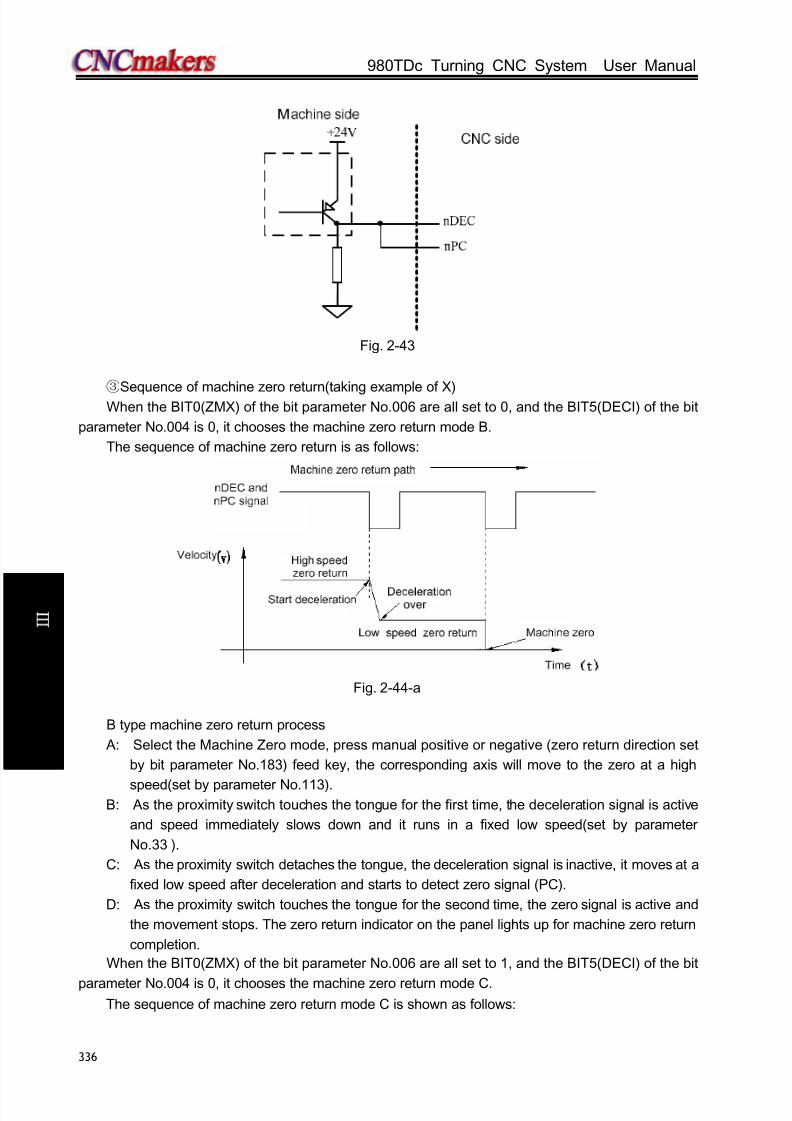
8/17/2019 980TDc CNC Turning Controller User Manual
http://slidepdf.com/reader/full/980tdc-cnc-turning-controller-user-manual 351/461
GSK980TDc Turning CNC System User Manual
336
C onn e c t i on
Fig. 2-43
③Sequence of machine zero return(taking example of X)When the BIT0(ZMX) of the bit parameter No.006 are all set to 0, and the BIT5(DECI) of the bit
parameter No.004 is 0, it chooses the machine zero return mode B.
The sequence of machine zero return is as follows:
Fig. 2-44-a
B type machine zero return process
A: Select the Machine Zero mode, press manual positive or negative (zero return direction set
by bit parameter No.183) feed key, the corresponding axis will move to the zero at a high
speed(set by parameter No.113).B: As the proximity switch touches the tongue for the first time, the deceleration signal is active
and speed immediately slows down and it runs in a fixed low speed(set by parameter
No.33 ).
C: As the proximity switch detaches the tongue, the deceleration signal is inactive, it moves at a
fixed low speed after deceleration and starts to detect zero signal (PC).
D: As the proximity switch touches the tongue for the second time, the zero signal is active and
the movement stops. The zero return indicator on the panel lights up for machine zero return
completion.
When the BIT0(ZMX) of the bit parameter No.006 are all set to 1, and the BIT5(DECI) of the bit
parameter No.004 is 0, it chooses the machine zero return mode C.The sequence of machine zero return mode C is shown as follows:

8/17/2019 980TDc CNC Turning Controller User Manual
http://slidepdf.com/reader/full/980tdc-cnc-turning-controller-user-manual 352/461
Chapter 2 Definition and Connection of Interface Signal
337
C onn e c t i on
Decel erati on swit ch
Zero r eturn
speed
Vel ocity (v )
High return speed
Low return
speed
Return
fini sh
Ti me (t)
D e c e l e r a t e s
t o s t o p
Reversel y
Fig. 2-44-b
C type machine zero return process
A: Select the Machine Zero mode, press manual positive or negative (zero return direction set
by bit parameter No.183) feed key, the corresponding axis will move to the zero at a high
speed(set by parameter No.113).
B: As the proximity switch touches the tongue for the first time, the deceleration signal is active.
The speed doesn’t slow down and it traverses on.
C: As the proximity switch detaches the deceleration switch, deceleration signal contact is
closed, the feed speed decelerates to zero, then it runs reversely by low return speed.D: As the proximity switch touches the deceleration switch for the second time in reverse
running, deceleration signal contact is cut off, it still runs by low return speed; as it detaches
the deceleration switch, deceleration signal contact is closed again, so the movement stops.
The zero return indicator for the corresponding axis on the panel lights up for zero return
completion.
2.8.4 Spindle control
Relevant signal (by standard PLC program)
Type Symbol Interface Address Function Remark
Input
signal
SAR CN15.6 X5.1 Spindle speed arrival signal It is valid when 0V
is inputSALM CN15.4 X5.3 Spindle abnormity alarm input
Output
signal
M03 CN62.4 Y0.3 Spindle rotation(CCW)
M04 CN62.5 Y0.4 Spindle rotation(CW)
M05 CN62.6 Y0.5 Spindle stop
SCLP CN62.7 Y0.6 Spindle clamped
SPZD CN62.8 Y0.7 Spindle brake
SVF CN62.37 Y3.0 Spindle servo OFF
SFR CN15.22 Y5.2 Spindle rotation(CW)Its function is
consistent with
that of M03

8/17/2019 980TDc CNC Turning Controller User Manual
http://slidepdf.com/reader/full/980tdc-cnc-turning-controller-user-manual 353/461
GSK980TDc Turning CNC System User Manual
338
C onn e c t i on
SRV CN15.23 Y5.3 Spindle rotation(CCW)
Its function is
consistent with
that of M04
Command
format
M03 Spindle rotation(CCW)
M04 Spindle rotation(CW)
M05 Spindle stop
M20 Spindle clamped They are valid in
analog spindleM21 Spindle released
Control parameter
Bit parameter
K 1 0 RSJG
RSJG =1: CNC not turn off M03, M04, M08, M32 output signals when pressing key;
=0: CNC turns off M03, M04, M08, M32 output signals when pressing key.
K 1 7 SCLP SALM SSTP SONC
SCLP =1: The spindle clamped command executes clamping the 2nd spindle when the
multi-spindle is valid.
=0: The spindle clamped command executes clamping the 1st spindle when the
multi-spindle is valid.
SALM =1: The system alarms when the spindle abnormal detection input signal is LOW (it is
turned off with 0V);
=0: The system alarms when the spindle abnormal detection input signal is HIGH (it isturned on with 0V) .
SSTP =1: The analog voltage is closed when the spindle stops;
=0: The analog voltage is not closed when the spindle stops.
SONC = 1: Spindle is disabled when clamping
= 0: Spindle motor torque decreases to 0 when spindle is clamping;1 7 5 SAR
Bit6 1: The spindle SAR signal is checked before cutting;0: The spindle SAR signal is not checked before cutting.
Data parameter
0 7 2 SAR_DELEYDelay check time (ms) of the spindle speed arrival.
D T 0 5 MTIME
Execution time of M code (ms)
D T 1 0 SPDDLT
Spindle braking delay output time after spindle stop (M05) is output
D T 1 1 SPZDTIME
Spindle braking output time (ms)

8/17/2019 980TDc CNC Turning Controller User Manual
http://slidepdf.com/reader/full/980tdc-cnc-turning-controller-user-manual 354/461
Chapter 2 Definition and Connection of Interface Signal
339
C onn e c t i on
D T 2 3 SVF_DELEY
Delay time before spindle motor torque decrease to 0 when spindle starts clamping;
D C 0 0 SPZERO
Spindle zero speed output range (m/min);
Signal connection
M03, M04, M05, SPZD signal output circuit is shown in Fig. 2-45A:
Fig. 2-45A
SAR, SALM signal input circuit is shown in Fig.2-45B:
Fig.2-45B
Operation sequence defined by standard PLC program)
Spindle operation sequence is show in Fig 2-46:
Fig. 2-46 spindle rotation(CW/CCW) sequence
Note: T2 is the delay time from sending the spindle stop signal to sending the spindle brake signal; T3 is the
spindle brake hold t ime.
Function description defined by standard PLC program)
① After the CNC is turned on, when M05 output is valid, M03 or M04 is executed, M03 or M04
output is valid and remains, at the time, M05 output is closed; when M03 or M04 output is valid, M05
is executed, M03 or M04 is closed, M05 output is valid and remains; the spindle brake SPZD signal
output delay is set by No.087(delay time from the spindle stop signal output to the spindle brake
SPZD signal output), the hold time of the brake signal is set by No. 089(the spindle brake output
time).
CW/CCW
T3 T2
Brake
Stop
Stop signal
+5V +24V 机床侧CNC Machine side
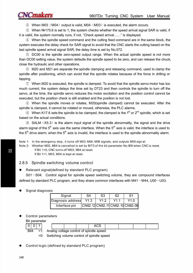
8/17/2019 980TDc CNC Turning Controller User Manual
http://slidepdf.com/reader/full/980tdc-cnc-turning-controller-user-manual 355/461
GSK980TDc Turning CNC System User Manual
340
C onn e c t i on
② When M03(M04)output is valid, M04(M03)is executed, the alarm occurs.
③ When 175.6 is set to 1, the system checks whether the speed arrival signal SAR is valid, if
it is valid, the system normally runs, if not, “Check speed arrival……” is displayed.
④ When the spindle speed command and the cutting feed command are in the same block, the
system executes the delay check for SAR signal to avoid that the CNC starts the cutting based on the
last spindle speed arrival signal SAR, the delay time is set by No.072.
⑤ DC00 is the spindle zero-speed output range. When the actual spindle speed is not more
than DC00 setting value, the system defaults the spindle speed to be zero, and can release the chuck,
close the hydraulic and other operations.
⑥ M20 and M21 are separate the spindle clamping and releasing command, used to clamp the
spindle after positioning, which can avoid that the spindle rotates because of the force in drilling or
tapping.
⑦ When M20 is executed, the spindle is clamped. To avoid that the spindle servo motor has too
much current, the system delays the time set by DT23 and then controls the spindle to turn off the
servo, at the time, the spindle servo reduces the motor excitation and the position control cannot be
executed, but the position check is still enabled and the position is not lost.
⑧ When the spindle moves or rotates, M20(spindle clamped) cannot be executed. After the
spindle is clamped, it cannot be rotated or moved, otherwise, the PLC alarms.
⑨ When K17.6 sets the spindle to be clamped, the clamped is the 1st or 2nd spindle, which is set
based on the actual conditions.
⑩ SALM(X5.3)is the alarm input signal of the spindle abnormality, the signal and the drive
alarm signal of the 5th axis use the same interface. When the 5 th axis is valid, the interface is used to
the 5th drive alarm; when the 5th axis is invalid, the interface is used to the spindle abnormality alarm.
Note 1: In the emergency stop, it turns off M03, M04, M08 signals, and outputs M05 signal;
Note 2: Whether M03, M04 is cancelled is set by BIT3 of the bit parameter No.009 when CNC is reset.
If Bit 1=0, CNC turns of f M03, M04 at reset;
If Bit 1=1, M03, M04 is kept at reset.
2.8.5 Spindle switching volume contro l
Relevant signal(defined by standard PLC program)
S01~S04: Control signal for spindle speed switching volume, they are compound interfaces
defined by standard PLC program, and they share common interfaces with M41~M44, U00~U03.
Signal diagnosis Signal S4 S3 S2 S1
Diagnosis address Y1.3 Y1.2 Y1.1 Y1.0
Interface pin CN62.12 CN62.11 CN62.10 CN62.09
Control parameters
Bit parameter
0 0 1 ACS
Bit4 =1: Analog voltage control of spindle speed
=0: Switching volume control of spindle speed
Control logic (defined by standard PLC program)
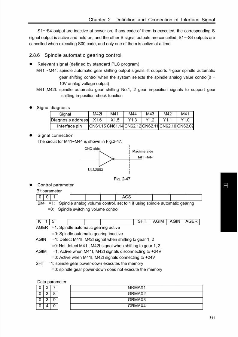
8/17/2019 980TDc CNC Turning Controller User Manual
http://slidepdf.com/reader/full/980tdc-cnc-turning-controller-user-manual 356/461
Chapter 2 Definition and Connection of Interface Signal
341
C onn e c t i on
S1~S4 output are inactive at power on. If any code of them is executed, the corresponding S
signal output is active and held on, and the other S signal outputs are cancelled. S1~S4 outputs are
cancelled when executing S00 code, and only one of them is active at a time.
2.8.6 Spindle automatic gearing control
Relevant signal (defined by standard PLC program)
M41~M44: spindle automatic gear shifting output signals. It supports 4-gear spindle automatic
gear shifting control when the system selects the spindle analog value control(0~
10V analog voltage output)
M41I,M42I: spindle automatic gear shifting No.1, 2 gear in-position signals to support gear
shifting in-position check function
Signal diagnosis
Signal M42I M41I M44 M43 M42 M41
Diagnosis address X1.6 X1.5 Y1.3 Y1.2 Y1.1 Y1.0
Interface pin CN61.15 CN61.14 CN62.12 CN62.11 CN62.10 CN62.09
Signal connection
The circuit for M41~M44 is shown in Fig.2-47:
Fig. 2-47
Control parameter
Bit parameter
0 0 1 ACS
Bit4 =1: Spindle analog volume control, set to 1 if using spindle automatic gearing
=0: Spindle switching volume control
K 1 5 SHT AGIM AGIN AGER
AGER =1: Spindle automatic gearing active
=0: Spindle automatic gearing inactive
AGIN =1: Detect M41I, M42I signal when shifting to gear 1, 2
=0: Not detect M41I, M42I signal when shifting to gear 1, 2
AGIM =1: Active when M41I, M42I signals disconnecting to +24V
=0: Active when M41I, M42I signals connecting to +24V
SHT =1: spindle gear power-down executes the memory
=0: spindle gear power-down does not execute the memory
Data parameter
0 3 7 GRMAX1
0 3 8 GRMAX20 3 9 GRMAX3
0 4 0 GRMAX4

8/17/2019 980TDc CNC Turning Controller User Manual
http://slidepdf.com/reader/full/980tdc-cnc-turning-controller-user-manual 357/461
GSK980TDc Turning CNC System User Manual
342
C onn e c t i on
GRMAX1,GRMAX2, GRMAX3, GRMAX4: The respective max. speeds of spindle gear 1, 2, 3, 4
when analog voltage output is 10V. Spindle speeds for M41, M42, M43, M44 when spindle automatic
gearing is active.
0 6 5 SFT1TME
Delay time 1 when automatic gearing signal output, see function description.
0 6 6 SFT2TME
Delay time 2 when automatic gearing signal output, see function description.
0 6 7 SFTREV
Output voltage of spindle gearing (0~10000, unit: mV)
0 6 7 SFTREV
The output voltage during spindle gear shift(0~10000, Unit: mV)
D T 0 0 SFT1TME
Time for original gear disable during spindle gear shift (ms),refer to function description for
details.
D T 0 1 SFT2TME
Delay time after spindle gear shift (ms), refer to function description for details.
Function description (defined by s tandard PLC program)
The spindle automatic gearing is active only under the spindle analog voltage control (BIT4 of thebit parameter No.001 set to 1) and the BIT 7 of the bit parameter No.164 is set to 1; if the spindle auto
gearing is inactive, alarm will be issued when M41~M44 is being executed and only one of them is
active at a time.
When spindle auto gearing is used to control automatic spindle mechanical gear switching, as
CNC executes S code, it calculates the analog voltage output to spindle servo or frequency
inverter based on the parameter of the current gear by M4n (M41~M44 to data parameters
No.037~No.040 respectively) to make the actual speed to be consistent with the S code.
When CNC is powered on, the spindle gear memorizing is set by the BIT1 of bit parameter
No.168.
If the BIT4 of bit parameter No.001 is 0, the spindle gear is not memorized at repowering after
power down, and the gear 1 will be defaulted, M41~M44 are not output. If BIT4 of bit parameter
No.001 is 1, the spindle gear is memorized at repowering after power down.
No gearing is done if the specified gear is consistent with the current gear. If not, gearing will be
performed, and the process defined by standard ladders is shown in the following:
①Execute any of M41, M42, M43, M44 codes, output analog voltage to spindle servo or
frequency inverter according to a value set by data parameter No.067 (Unit: mV);
② After a delay (gearing time 1) by the DT00, turn off the original gear output signal and output
the new gearing signal;
③If the gear is 1 or 2, and the BIT6 of the bit parameter No.164 is 1, it jumps to ④, or else it jumps to ⑤;
④Check the gear in-position input signal M41I, M42I, it jumps to ⑤ if the gear in-position is

8/17/2019 980TDc CNC Turning Controller User Manual
http://slidepdf.com/reader/full/980tdc-cnc-turning-controller-user-manual 358/461
Chapter 2 Definition and Connection of Interface Signal
343
C onn e c t i on
done; if not, the CNC waits the gear in-position signal;
⑤ After a delay (gearing time 2) by DT01, output spindle analog voltage by the current gear
according to a value set by data parameter No.037~No.040 (gear 1~4 ) and finish the gearing.
Note: The output of M41~M44 is held on when CNC is reset or i emergency stop, which is defined by
standard PLC ladder.
2.8.7 Spindle eight-point orientation function
Related signals
defined by s tandard PLC program
Type Symbol Interface Address Function Remark
Input
signal
COIN CN15.8 X5.2 Orientation completion signal
It is valid when
0V is inputSALM CN15.4 X5.3Spindle abnormality alarm
signal
Output
signal
STAO CN62.41 Y3.4 Spindle orientation start signal
SP0 CN62.42 Y3.5 Orientation position 0
SP1 CN62.43 Y3.6 Orientation position 1
SP2 CN62.44 Y3.7 Orientation position 2
SFR CN15.22 Y5.2 Spindle rotation (CW)
SRV CN15.23 Y5.3 Spindle rotation (CCW)
Note 1: STAO signal and the rotation CCW signal of the 2nd
spindle M64 are mult iplexed by the interface, so,
eight-point orientation function is invalid when the multiple spindle function i s valid.
Note 2: STAO, SP0, SP1, SP2 signal and macro output #1102 #1105 are multiplexed by the interface, so,
#1102 #1105 is invalid when the eight-point orientation function i s valid.
Command format
M51~M58: spindle orientation command
M50 : cancel spindle orientation command
M50~M58 corresponding to the orientation output are shown below:
Output signal
Programming command
SP2
(Y3.7)
SP1
(Y3.6)
SP0
(Y3.5)
STAO
(Y3.4)
M50 * * * 0M51 0 0 0 1
M52 0 0 1 1
M53 0 1 0 1
M54 0 1 1 1
M55 1 0 0 1
M56 1 0 1 1
M57 1 1 0 1
M58 1 1 1 1
Note: When M50 is executed, STAO output is disabled, SP0, SP1, SP2 output continues.
Control parameter

8/17/2019 980TDc CNC Turning Controller User Manual
http://slidepdf.com/reader/full/980tdc-cnc-turning-controller-user-manual 359/461
GSK980TDc Turning CNC System User Manual
344
C onn e c t i on
K 1 5 SPOR
SPOR =1: The spindle eight-orientation function is valid.
=0: The spindle eight-orientation function is invalid.
K 1 7 SALM
SALM =1: The system alarms when the spindle abnormality check input signal is LOW(it is not
connected with 0V).
=0: The system alarms when the spindle abnormality check input signal is HIGH(it is
connected with 0V).
Functional descrip tion(standard PLC program definition)1. After the positioning function commands M51~M58 are executed, PLC→Drive executes the
orientation selection signal SP0, SP1, SP2 to confirm the orientation position.
2. Delay 40ms, PLC→Drive executes the spindle orientation start signal STAO;(after the system
delays 100ms, the spindle rotation(CW/CCW) is disabled, at the same time, the system starts to
check the orientation completion signal (COIN).3. Drive unit starts the orientation.
4. After the drive unit orientation is completed, Drive →PLC outputs the spindle completion signal
COIN;
5. After PLC receives the spindle orientation completion signal COIN, the spindle orientation is
completed, but the spindle orientation signal STAO keeps the output.
6. When M51~M58 is input again, the spindle oriented to another position.
7. After the orientation is completed and when M50 is executed or the spindle orientation is
operated, PLC closes the spindle orientation signal STAO output and the drive unit cancels the
positioning function.
8. When the system has not received the orientation completion signal after the PLC sends the
orientation completion signal for 10000ms, it alarms “the spindle orientation time being long”.
9. Before the orientation, the spindle can rotate or stop; the spindle stops after the orientation.
Note 1: The drive is for the spindle servo drive unit.
Note 2: When the function i s selected, the spindle servo drive unit is matched and is valid in the external
speed control mode.
Orientation sequence drawing
Orientation function wiring diagram between GSK980TDc and DAP03
GSK980TDc signal interface DAP03 signal interface
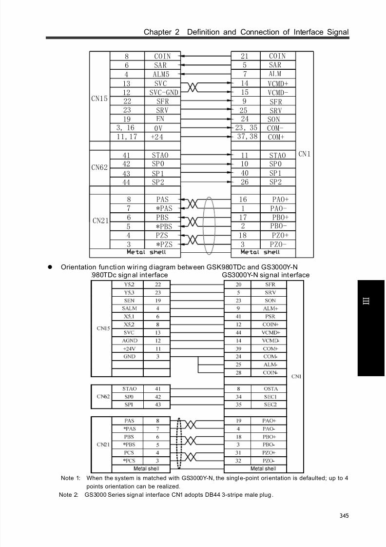
8/17/2019 980TDc CNC Turning Controller User Manual
http://slidepdf.com/reader/full/980tdc-cnc-turning-controller-user-manual 360/461
Chapter 2 Definition and Connection of Interface Signal
345
C onn e c t i on
CN1
SRVSFR
2322CN15
0V+2 4
4 ALM5 7 AL M
COM-COM+
SON24
SVC
SVC-GND
13
12
14 VCMD+
9 SFRSRV
15VCMD-
25
16 PAO+ 1 PAO- 17 PBO+ 2 PBO-
18 PZO+ 3 PZO-
CN21
8 PAS7 *PAS6 PBS5 *PBS4 PZS3 *PZS
SAR56 SAR
41 STAOSP042
44 SP243 SP1
11104026
STAOSP0
SP1SP2
CN62
8 COIN 21 COIN
19 EN
37,3823 , 353, 16
11,17
Orientation function wiring d iagram between GSK980TDc and GS3000Y-N
GSK980TDc signal interface GS3000Y-N signal interface
Note 1: When the system is matched with GS3000Y-N, the single-point orientation is defaulted; up to 4points orientation can be realized.
Note 2: GS3000 Series signal interface CN1 adopts DB44 3-stripe male plug .

8/17/2019 980TDc CNC Turning Controller User Manual
http://slidepdf.com/reader/full/980tdc-cnc-turning-controller-user-manual 361/461
GSK980TDc Turning CNC System User Manual
346
C onn e c t i on
2.8.8 Spindle Cs axis control function
Related signals defined by standard PLC program)
Type Symbol Interface Address Funct ion Remark
Input
signal
VPO CN15.5 X5.0Spindle speed/position control
stateIt is valid when
0V is input ALM5 CN15.4 X5.3
Alarm signal of the 5th drive
unit
Output
signal
VP CN15.20 Y5.0Spindle speed/position control
switch output
TAP CN15.21 Y5.1
The 2nd gain selection signal
of the spindle speed(used to
the rigid tapping)
SFR CN15.22 Y5.2 Spindle rotation CW
SRV CN15.23 Y5.3 Spindle rotation CCW
Command format
M14: The spindle is switched from the speed control mode into the position
M15: The spindle is switched from the position control mode into the speed
Note: When the spindle is rotary, Cs function is valid and the corresponding spindle servo drive unit is
speed/position switch working mode, the spindle speed/position cont rol switch is valid.
Control parameters
State parameters
0 0 1 Analog
spindle
Bit4 =1: Spindle speed analog control. When the spindle automatic gear change function is
used, it must be set to 1;
=0: Spindle speed switch control.
1 8 7 RCSY ROSY ROTY
Bit5 =1: Cs function of Y axis is valid/invalid(power-on again);
=0: Cs function of Y axis is valid/invalid(power-on again).
Bit 1, Bit0: 00 sets Y to be the linear axis; 01 sets Y to be the rotary axis(A type); 11 sets Y to be
the rotary axis(B type); 10 sets Y to be invalid.
1 8 9 RCS4 ROS4 ROT4
Bit5 =1: Cs function of the 4th axis is valid/invalid(power-on again);
=0: Cs function of the 4th axis is valid/invalid(power-on again).
Bit 1, Bit0: 00 sets the 4th to be the linear axis; 01 sets the 4th to be the rotary axis(A type); 11 sets
the 4th to be the rotary axis(B type); 10 sets the 4th to be invalid.
1 9 1 RCS5 ROS5 ROT5
Bit5 =1: Cs function of the 5th axis is valid/invalid(power-on again);

8/17/2019 980TDc CNC Turning Controller User Manual
http://slidepdf.com/reader/full/980tdc-cnc-turning-controller-user-manual 362/461
Chapter 2 Definition and Connection of Interface Signal
347
C onn e c t i on
=0: Cs function of the 5th axis is valid/invalid(power-on again).
Bit 1, Bit0: 00 sets the 5th to be the linear axis; 01 sets the 5th to be the rotary axis(A type); 11 sets
the 5th to be the rotary axis(B type); 10 sets the 5th to be invalid.
K 1 5 RCS RSCS
RCS =1: Cs function of the spindle is valid.
=0: Cs function of the spindle is invalid.
RSCS =1: The spindle contour control is disabled in emergency stop, reset.
=0: The spindle contour control is enabled in emergency stop, reset.
Note: K15.7 sets whether all Cs functions are valid, o187.5, o189.5, o191.5 set whether Cs functions of
the special axis is valid. When the multiple spindle function is valid, Cs function of only one axis is valid.
Function description defined by standard PLC program)
1. Control logic
1) After M14 is executed, PLC→Drive outputs the spindle speed/position control mode switch
signal;2) Drive unit starts the switch control mode. After the switch is completed, Drive→PLC outputs
the speed/position switch state signal VPO;
3) After the PLC receives the spindle speed/position switch state signal VPO, the spindle contour
control switch signal CON is set to 1. After the system has checked CNC spindle contour control
switch end signal FSCSL, M14 execution is ended. The spindle control mode switch is ended.
2. M15 execute processes are the same those of M14.
3. on the panel is equal to the spindle speed/position control mode switch in Manual
mode. In Manual/MPG mode, press and the CNC starts the spindle speed/position control
mode switch. After the CNC is switched into the spindle position control mode, the spindle orientation
indicator is ON, at the time, Cs position movement is performed. Press again and the CNC is
switched into the spindle speed control mode and the spindle orientation indicator is OFF. (For
980TDc-V, it is key on the panel)
4. Before switch, the spindle can rotate or stop. After switch, the spindle stops.
5. When the spindle is in Cs contour control mode, the spindle rotation(CW/CCW) output is
invalid.6. When the spindle is in the external speed control mode, the manual operation of Cs axis is
invalid.
7. When the alarm occurs in the servo or because of the too long switch time or the reset or
emergency stop appears in switch, PLC switches the spindle into the speed control state.
8. When PLC K15.6 is set to 1, the spindle contour control is disabled in emergency stop, reset.
PLC switches the spindle into the speed control state.

8/17/2019 980TDc CNC Turning Controller User Manual
http://slidepdf.com/reader/full/980tdc-cnc-turning-controller-user-manual 363/461
GSK980TDc Turning CNC System User Manual
348
C onn e c t i on
Connection diagram between GSK980TDc and DAP03 (taking example of Cs of the 5th
axis)
CN1
SRV
SFR
23
22
CN15
VPOVP
520
ZOUT-
DIR5-15
0V
11 +24
104 ALM5
PC5
DIR5
CP5+1
14
2
CP5-
SIGN-34
ZOUT+24
719
ALM
PULS-
SIGN+
PULS+42
33
28
COM-COM+
SON4
SVCSVC-GND
1312
14 VCMD+
9 SFR
SRV
VP1244 VPO
15 VCMD-
25
16 PAO+ 1 PAO- 17 PBO+ 2 PBO-
18 PZO+ 3 PZO-
CN21
8 PAS7 *PAS6 PBS
5 *PBS4 PZS3 *PZS
EN519
21 TAP 41 TAP
6 SAR 5 SAR
3/9 23/ 3537/38
Wiring diagram between GSK980TDc and GS3000Y-N spindle servo unit (the 5th
axis isCs axis in the fol lowing example)
GSK980TDc signal interface GS3000Y-N signal interface
GSK980TDc signal interface DAP03 signal interface
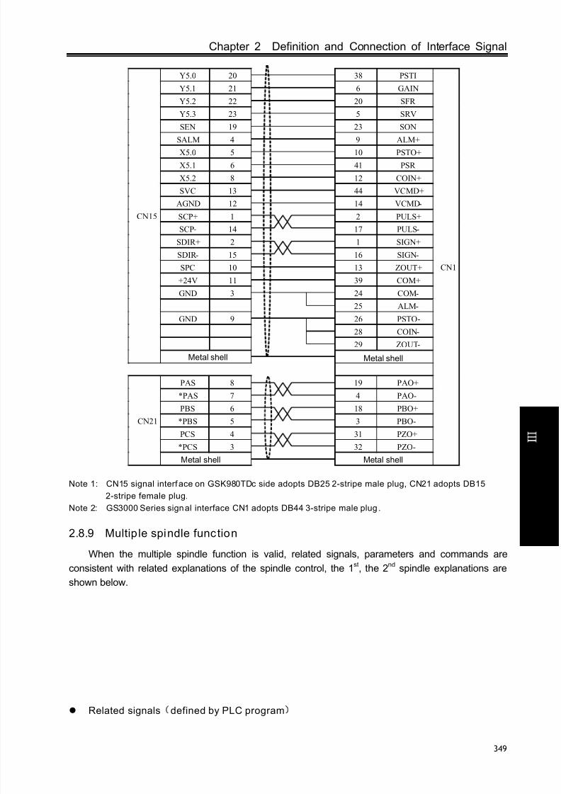
8/17/2019 980TDc CNC Turning Controller User Manual
http://slidepdf.com/reader/full/980tdc-cnc-turning-controller-user-manual 364/461
Chapter 2 Definition and Connection of Interface Signal
349
C onn e c t i on
Y5.0 20 38 PSTI
Y5.1 21 6 GAIN
Y5.2 22 20 SFR
Y5.3 23 5 SRV
SEN 19 23 SON
SALM 4 9 ALM+
X5.0 5 10 PSTO+
X5.1 6 41 PSR
X5.2 8 12 COIN+
SVC 13 44 VCMD+
AGND 12 14 VCMD-
SCP+ 1 2 PULS+
SCP- 14 17 PULS-
SDIR+ 2 1 SIGN+
SDIR- 15 16 SIGN-
SPC 10 13 ZOUT+
+24V 11 39 COM+
GND 3 24 COM-
25 ALM-
GND 9 26 PSTO -
28 COIN-
29 ZOUT-
CN15
Metal shell
PAS 8 19 PAO+
*PAS 7 4 PAO-
PBS 6 18 PBO+
*PBS 5 3 PBO-
PCS 4 31 PZO+
*PCS 3 32 PZO-
CN21
CN1
Metal shell
Metal shell Metal shell
Note 1: CN15 signal interface on GSK980TDc side adopts DB25 2-stripe male plug, CN21 adopts DB15
2-stripe female plug.
Note 2: GS3000 Series signal interface CN1 adopts DB44 3-stripe male plug .
2.8.9 Multip le spindle function
When the multiple spindle function is valid, related signals, parameters and commands areconsistent with related explanations of the spindle control, the 1st, the 2nd spindle explanations are
shown below.
Related signals defined by PLC program)

8/17/2019 980TDc CNC Turning Controller User Manual
http://slidepdf.com/reader/full/980tdc-cnc-turning-controller-user-manual 365/461
GSK980TDc Turning CNC System User Manual
350
C onn e c t i on
Type Symbol Interface Address Funct ion Remark
Input
signal
VPO2 CN61.40 X3.3The 2n spindle speed/position control
stateMultiplex with
the chuck
in-position
signal
SALM2 CN61.41 X3.4The 2nd spindle abnormality alarm
signal
Output
signal
VP2 CN62.36 Y2.7The 2n spindle speed/ position control
switch output
TAP2 CN62.39 Y3.2
The 2n gain selection signal of the 2n
spindle speed loop (used to rigid
tapping)
M63 CN62.40 Y3.3 The 2nd spindle rotation(CW)
M64 CN62.41 Y3.4 The 2nd spindle rotation(CCW)
Note 1: TAP2, M63, M64 and macro output #1100 #1102 are multiplexed by the interface, so #1100 #1102
are invalid when the multiple spindle function is valid.
Note 2: SALM2, VPO2 and the chuck in-position signals NQPJ, WQPJ are mult iplexed by the interface, so,
the system does not check the chuck in-position signal.
Command format
M63 the 2nd spindle rotates (CW)
M64 the 2nd spindle rotates (CCW)
M65 the 2nd spindle stops
M24 the 2nd spindle is switched from the speed control mode into the position control mode
M25 the 2nd spindle is switched from the position control mode into the speed control mode. The
speed control mode is defaulted after the system is turned on.
Note: Only the 4th
is rotary axis and Cs function of the 4th
is valid, at the same time, the corresponding spindle
servo drive unit is in speed/position switch working mode, the switch between the speed control and the
position control of the 2nd
spindle is valid.
Control parameters
1 8 9 RCS4 ROS4 ROT4
Bit5 =1: Cs function of the 4th axis is valid/invalid(power-on again);
=0: Cs function of the 4th axis is valid/invalid(power-on again).
Bit 1, Bit0: 00 sets the 4th
to be the linear axis; 01 sets the 4th
to be the rotary axis(A type); 11 setsthe 4th to be the rotary axis(B type); 10 sets the 4th to be invalid.
1 9 6 MSI CSS MSEN
Bit7 1: The multiple spindle control B type;
0: The multiple spindle control A type.
Bit6 1: In the multiple spindle control, the system separately controls Cs contour of each
spindle;
0: In the multiple spindle control, the system controls the Cs contour of only the 1st
spindle.
Bit4 1: The multiple spindle control function is valid;0: The multiple spindle control function is invalid;

8/17/2019 980TDc CNC Turning Controller User Manual
http://slidepdf.com/reader/full/980tdc-cnc-turning-controller-user-manual 366/461
Chapter 2 Definition and Connection of Interface Signal
351
C onn e c t i on
K 1 5 RCS RSCS
RCS =1: The spindle Cs function is valid;
=0: The spindle Cs function is invalid.
RSCS =1: The spindle contour control is disabled in emergency stop, reset;
=0: The spindle contour control is enabled in emergency stop, reset.
K 1 7 MSEN SALM2
MSEN =1: The multiple spindle control function is valid;
=0: The multiple spindle control function is invalid.
SALM2 =1: The system alarms when the check input signal of the 2nd spindle abnormality is
LOW;
=0: The system alarms when the check input signal of the 2nd spindle abnormality is
HIGH;
Function description(defined by the standard PLC program)
1.1. After the multiple spindle control function setting is valid, the system defaults to the 1
st
spindle control after power-on;
1.2. When M03, M04, M05 is executed, the corresponding signal of the 1st spindle outputs, at
that time, the system sets the 1st spindle control, hereafter, the S command being executed will
change the 1st spindle speed. In a similar way, M63, M64, M65 is executed, the corresponding signal
of the 2nd spindle outputs, at the time, the corresponding signal of the 2nd spindle outputs, and is
switched into the 2nd spindle control, after that, the executed S command will change the 2nd spindle
speed.
1.3. The spindle switch is invalid in rigid tapping.
1.4. The manual CW, CCW, STOP, SPINDLE OVRRRIDE keys on the panel are valid only to the
1st
spindle. When the current system is controlled by the 2nd
spindle, the manual control key of thespindle on the panel still controls the 1st spindle.
1.5. The spindle override of the 2nd spindle is fixed to 100%.
1.6. Cs axis control of two spindles can be separately switched and the current used spindle has
no requirements, that is, when the current is the 1st(2nd) spindle, the 2nd (1st) spindle executes the Cs
switch.
Cs control logic of the 2nd
spindle
1.1. After M24 is execute, PLC→Drive sends the 2nd spindle speed/position control mode switch
signal VP2;
1.2 Drive unit starts the switch control mode. After the switch is completed, Drive→PLC outputs
the speed/position switch state signal VPO2;1.3. After the PLC receives the spindle speed/position switch state signal VPO2, the 2 nd spindle
contour control switch signal CON(G127.7) is set to 1. After the system has checked the 2 nd spindle
contour control switch end signal FSCSL(F144.1), M24 execution is ended. The spindle control mode
switch is ended.
2. M25 execute processes are the same those of M24.
3. M25 only cancels M24 executing the speed/position switch. Executing M25 cannot switch the
system into the speed control mode when executing M29 switches the spindle into Cs contour
control.
4. on the panel is only used to Cs switch of the 1st
spindle. (For 980TDc-V, it is keyon the panel)
5. Before switch, the spindle can rotate or stop. After switch, the spindle stops.

8/17/2019 980TDc CNC Turning Controller User Manual
http://slidepdf.com/reader/full/980tdc-cnc-turning-controller-user-manual 367/461
GSK980TDc Turning CNC System User Manual
352
C onn e c t i on
6. When the spindle is in Cs contour control mode, the spindle rotation(CW/CCW) output is
invalid.
7. When the spindle is in the external speed control mode, the manual operation of Cs axis is
invalid.
8. When the alarm occurs in the servo or because of the too long switch time or the reset or
emergency stop appears in switch, PLC switches the spindle into the speed control state.
9. When PLC K15.6 is set to 1, the spindle contour control is disabled in emergency stop, reset.
PLC switches the spindle into the speed control state.
10. When PLC K17.7 is set to 1, the multiple spindle function is enabled, and the system does
not check the chuck in-position signal.
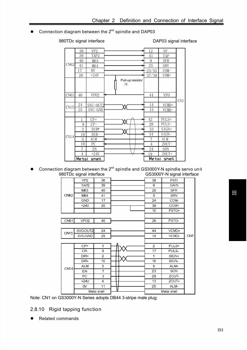
8/17/2019 980TDc CNC Turning Controller User Manual
http://slidepdf.com/reader/full/980tdc-cnc-turning-controller-user-manual 368/461
Chapter 2 Definition and Connection of Interface Signal
353
C onn e c t i on
Connection diagram between the 2nd
spindle and DAP03
CN1
M64M63
4140
CN14
VPO2
TAP2
40
39
ZOUT+
DIR-10
4 +24V
105 ALM
PC
DIR
CP+1
92
CP-
SIGN-34
ZOUT-
19
74
ALM
PULS-SIGN+
PULS+42
3328
COM+
SON24
SVC-OUT2SVC-GND
2425
14 VCMD+
9 SFRSRV
TAP41
44 VPO
15 VCMD-
25
COM-0V17
20 +24V
CN62
CN15
CN61
Pull-up resistor2K
36 VP2 12 VP
7 EN
23/3537/38
Connection diagram between the 2nd
spindle and GS3000Y-N spindle servo un it GSK980TDc signal interface GS3000Y-N signal interface
Note: CN1 on GS3000Y-N Series adopts DB44 3-stripe male plug;
2.8.10 Rigid tapping function
Related commands
DAP03 signal interfaceGSK980TDc signal interface
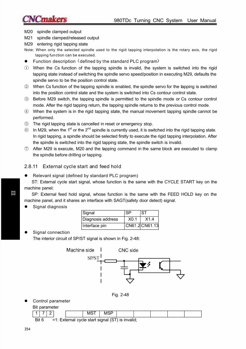
8/17/2019 980TDc CNC Turning Controller User Manual
http://slidepdf.com/reader/full/980tdc-cnc-turning-controller-user-manual 369/461
GSK980TDc Turning CNC System User Manual
354
C onn e c t i on
M20 spindle clamped output
M21 spindle clamped/released output
M29 entering rigid tapping state
Note: When only the selected spindle used to the rigid tapping interpolation is the rotary axis, the rigid
tapping function can be executed.
Function description
defined by the standard PLC program)
① When the Cs function of the tapping spindle is invalid, the system is switched into the rigid
tapping state instead of switching the spindle servo speed/position in executing M29, defaults the
spindle servo to be the position control state.
② When Cs function of the tapping spindle is enabled, the spindle servo for the tapping is switched
into the position control state and the system is switched into Cs contour control state.
③ Before M29 switch, the tapping spindle is permitted to the spindle mode or Cs contour control
mode. After the rigid tapping return, the tapping spindle returns to the previous control mode.
④ When the system is in the rigid tapping state, the manual movement tapping spindle cannot be
performed.
⑤ The rigid tapping state is cancelled in reset or emergency stop.
⑥ In M29, when the 1st or the 2nd spindle is currently used, it is switched into the rigid tapping state.
In rigid tapping, a spindle should be selected firstly to execute the rigid tapping interpolation. After
the spindle is switched into the rigid tapping state, the spindle switch is invalid.
⑦ After M29 is execute, M20 and the tapping command in the same block are executed to clamp
the spindle before drilling or tapping.
2.8.11 External cycle start and feed hold
Relevant signal (defined by standard PLC program)
ST: External cycle start signal, whose function is the same with the CYCLE START key on themachine panel;
SP: External feed hold signal, whose function is the same with the FEED HOLD key on the
machine panel, and it shares an interface with SAGT(safety door detect) signal.
Signal diagnosis
Signal SP ST
Diagnosis address X0.1 X1.4
Interface pin CN61.2 CN61.13
Signal connection
The interior circuit of SP/ST signal is shown in Fig. 2-48:
Fig. 2-48
Control parameter
Bit parameter1 7 2 MST MSP
Bit 6 =1: External cycle start signal (ST) is invalid;

8/17/2019 980TDc CNC Turning Controller User Manual
http://slidepdf.com/reader/full/980tdc-cnc-turning-controller-user-manual 370/461
Chapter 2 Definition and Connection of Interface Signal
355
C onn e c t i on
=0: External cycle start signal (ST) is valid;
Bit 5 =1: External stop signal (SP) is invalid;
=0: External stop signal (ST) is valid; the external feed hold switch is needed,
otherwise, “Feed hold” is displayed.
External connection circuit
The external connection circuit of SP, ST signals is shown in Fig. 2-49:
Fig. 2-49
2.8.12 Cooling control
Relevant signal (defined by standard PLC program)
Type Symbol Interface Address Funct ion Remark
Output signal M08 CN62.1 Y0.0 Cooling control output
Command formatM08 Cooing ON
M09 Cooling OFF
Signal connection
Its internal circuit is shown in Fig. 2-50:
Fig. 2-50 M08 internal circuit
Function description (defined by s tandard PLC program)
M09 is active, i.e. M08 is inactive, after CNC power on. To execute M08, M08 output is active and
cooling is turned on; to execute M09, M08 output is cancelled and cooling is turned off.
Note 1: M08 output is cancelled at CNC emergency stop.
Note 2: Whether M08 is cancelled is set by BIT3 of the bit parameter No.009 when CNC is reset.
When Bit1=0, M08 output is cancelled as CNC is reset;
When Bit1=1, M08 output is not cancelled as CNC is reset;
Note 3: There is no corresponding output signal for M09, and M08 output is cancelled if M09 is executed.
Note 4: The cool ing can be cont rol led by the key on operation panel, see details in OPERATION.
CN61 socket
G S K 9 8 0 T D b
SP
+24V
ST
Normal-close contact without lock

8/17/2019 980TDc CNC Turning Controller User Manual
http://slidepdf.com/reader/full/980tdc-cnc-turning-controller-user-manual 371/461
GSK980TDc Turning CNC System User Manual
356
C onn e c t i on
2.8.13 Lubr icating control
Relevant signal (defined by standard PLC program)
Type Symbol Interface Address Funct ion Remark
Output signal M32 CN62.2 Y0.1 Lubricating control output
Command
format
M32 Lubricating ON
M33 Lubricating OFF
Signal connection
The internal circuit is shown in Fig. 2-51:
Fig. 2-51 M32 circuit
Control parameter
PLC state parameter
K 1 0 RSJGRSJG =1: when is pressed, CNC does not close M03, M04, M08, M32 output signal.
=0: when is pressed, CNC closes M03, M04, M08, M32 output signal.
K 1 6 M32A
M32A =1: output lubricating in starting the system when the automatic lubricating is valid
=0: do not output lubricating in starting the system when the automatic lubricating is valid
PLC value
D T 1 3 MANLUBT
Time for manual lubricating ON (ms) (0: lubricating time is not limited);D T 0 1 6
Automatic lubricating time (0~2147483647ms)
D T 0 1 7
Automatic lubricating interval time (0~2147483647ms)
Function description
The lubricating defined by standard PLC program for this GSK980TDc system has two types:
Non-automatic and automatic lubricating, which are set by parameter:
DT17 =0: Non-automatic lubricating (same as version before)
DT17>0: Automatic lubricating, lubricating time DT17 and lubricating interval time DT16
available
1. Manual lubricating funct ion
Press on the machine operator panel and the system executes the lubricating output,
pressing it again and the system cancels the output. Execute M32 and the system executes the
output; execute M33 and the system stops it.
DT13>1: the system executes the timed lubricating output, and the output is executed by

8/17/2019 980TDc CNC Turning Controller User Manual
http://slidepdf.com/reader/full/980tdc-cnc-turning-controller-user-manual 372/461
Chapter 2 Definition and Connection of Interface Signal
357
C onn e c t i on
pressing , and is cancelled when the output exceeds the one set by DT13. After the system
executes M32, the lubricating output is executed within the time set by DT13 and it is cancelled.
Execute M33 in the time set by No. 112 and the output is cancelled.
2. Automatic lubricating
When K16.2 is set to 1, the system executes the lubricating in the time set by DT17, and thenstops the output. After it keeps the stop in the time set by DT16, it executes the lubricating again
repetitively, and executes the cycle in turn. In automatic lubricating, M32, M33, on the
machine panel are valid, and the lubricating time is the one set by DT17.
Note 1: The lubricating output is disabled in emergency stop;
Note 2: K No.0.10 Bit1 sets whether the lubricating output is cancelled in reset:
Bit1 0: the lubricating output is disabled in reset;
Bit1 1: the lubricating output remains unchanged in reset.
2.8.14 Chuck control Relevant signal (defined by standard PLC program)
DIQP: Chuck control input signal
DOQPJ: Inner chuck clamping output/outer chuck releasing output signal
DOQPS: Inner chuck releasing output/outer chuck clamping output signal
NQPJ: Inner chuck clamping in-position/outer chuck releasing in-position signal, sharing a
common interface with T08, M42I
WQPJ: Inner chuck releasing in-position/outer chuck clamping in-position signal, sharing a
common interface with T07, M41I
Note 1: The key on the operation panel of GSK980TDc-V can replace DIQP input signal, and the
diagnosis address is X0026.6.
Note 2: NQPJ, WQPJ with the 2nd
spindle signals SALM2, VPO2 multiplex interface, so, the system does not
check the chuck in-position signal when the multi-spindle function is valid.
Signal diagnosis
Signal DIQP NQPJ WQPJ DOQPJ DOQPS
Diagnosis address X0.2 X3.4 X3.3 Y1.4 Y1.5
Interface pin CN61.3 CN61.40 CN61.41 CN62.13 CN62.14
Control parameter
K 1 2 RCKC CCHU NYQP SLSP SLQP
SLQP =1: Chuck control function is active;
= 0: Chuck control function is inactive;
SLSP =1: Check chuck clamping when the chuck function is active;0: Does not check chuck clamping when the chuck function is active; if chuck is not
clamping, the spindle is disabled and an alarm is issued.
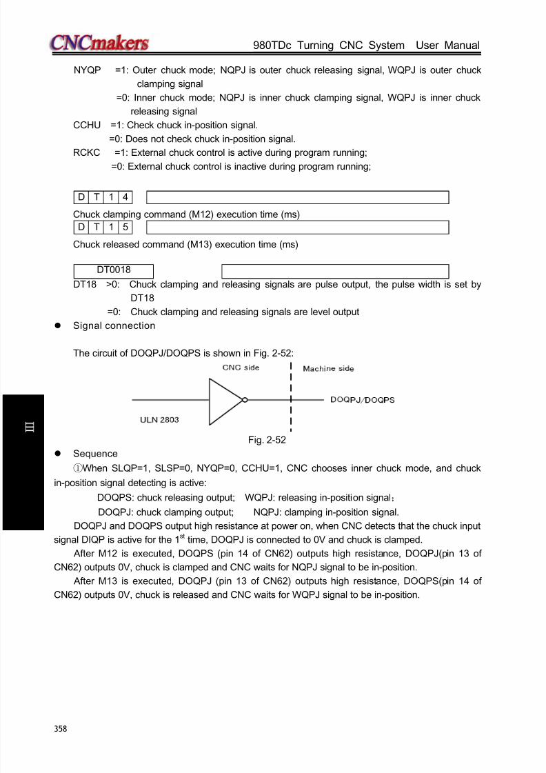
8/17/2019 980TDc CNC Turning Controller User Manual
http://slidepdf.com/reader/full/980tdc-cnc-turning-controller-user-manual 373/461
GSK980TDc Turning CNC System User Manual
358
C onn e c t i on
NYQP =1: Outer chuck mode; NQPJ is outer chuck releasing signal, WQPJ is outer chuck
clamping signal
=0: Inner chuck mode; NQPJ is inner chuck clamping signal, WQPJ is inner chuck
releasing signal
CCHU =1: Check chuck in-position signal.
=0: Does not check chuck in-position signal.
RCKC =1: External chuck control is active during program running;
=0: External chuck control is inactive during program running;
D T 1 4
Chuck clamping command (M12) execution time (ms)
D T 1 5
Chuck released command (M13) execution time (ms)
DT0018DT18 >0: Chuck clamping and releasing signals are pulse output, the pulse width is set by
DT18
=0: Chuck clamping and releasing signals are level output
Signal connection
The circuit of DOQPJ/DOQPS is shown in Fig. 2-52:
Fig. 2-52
Sequence
①When SLQP=1, SLSP=0, NYQP=0, CCHU=1, CNC chooses inner chuck mode, and chuck
in-position signal detecting is active:
DOQPS: chuck releasing output; WQPJ: releasing in-position signal;
DOQPJ: chuck clamping output; NQPJ: clamping in-position signal.
DOQPJ and DOQPS output high resistance at power on, when CNC detects that the chuck input
signal DIQP is active for the 1st
time, DOQPJ is connected to 0V and chuck is clamped. After M12 is executed, DOQPS (pin 14 of CN62) outputs high resistance, DOQPJ(pin 13 of
CN62) outputs 0V, chuck is clamped and CNC waits for NQPJ signal to be in-position.
After M13 is executed, DOQPJ (pin 13 of CN62) outputs high resistance, DOQPS(pin 14 of
CN62) outputs 0V, chuck is released and CNC waits for WQPJ signal to be in-position.
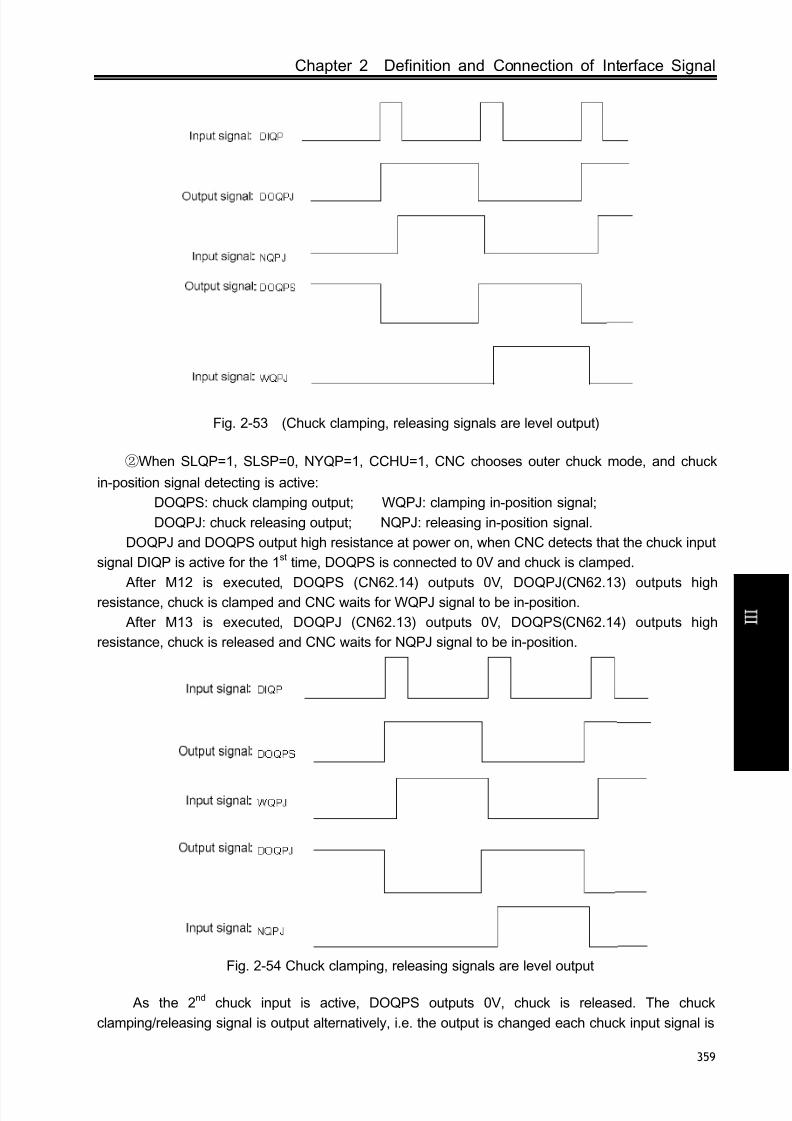
8/17/2019 980TDc CNC Turning Controller User Manual
http://slidepdf.com/reader/full/980tdc-cnc-turning-controller-user-manual 374/461
Chapter 2 Definition and Connection of Interface Signal
359
C onn e c t i on
Fig. 2-53 (Chuck clamping, releasing signals are level output)
②When SLQP=1, SLSP=0, NYQP=1, CCHU=1, CNC chooses outer chuck mode, and chuck
in-position signal detecting is active:
DOQPS: chuck clamping output; WQPJ: clamping in-position signal;
DOQPJ: chuck releasing output; NQPJ: releasing in-position signal.
DOQPJ and DOQPS output high resistance at power on, when CNC detects that the chuck input
signal DIQP is active for the 1st time, DOQPS is connected to 0V and chuck is clamped.
After M12 is executed, DOQPS (CN62.14) outputs 0V, DOQPJ(CN62.13) outputs highresistance, chuck is clamped and CNC waits for WQPJ signal to be in-position.
After M13 is executed, DOQPJ (CN62.13) outputs 0V, DOQPS(CN62.14) outputs high
resistance, chuck is released and CNC waits for NQPJ signal to be in-position.
Fig. 2-54 Chuck clamping, releasing signals are level output
As the 2nd chuck input is active, DOQPS outputs 0V, chuck is released. The chuck
clamping/releasing signal is output alternatively, i.e. the output is changed each chuck input signal is

8/17/2019 980TDc CNC Turning Controller User Manual
http://slidepdf.com/reader/full/980tdc-cnc-turning-controller-user-manual 375/461
GSK980TDc Turning CNC System User Manual
360
C onn e c t i on
active.
③The interlock between the chuck and the spindle
When SLQP=1, SLSP=0, M3 or M4 is active, the alarm is issued if M13 is executed and the
output is unchanged.
When SLQP=1, SLSP=0, CCHU=1, if M12 is executed in MDI or Auto mode, CNC does not
execute next code till it detects the chuck clamping in-position signal is active. When the chuck
input signal DIQP is active in Manual mode, the panel spindle CW, CCW key are inactive till it
detects the chuck clamping in-position signal is active. In spindle running or auto cycle processing,
DIQP input signal is inactive. And DOQPS, DOQPJ is held on at CNC reset and emergency stop.
2.8.15 Tailstock control
Relevant signal (defined by standard PLC program)
DOTWJ: Tailstock forward output signal
DOTWS: Tailstock backward output signal
DITW: Tailstock input signal, DITW and BDT share a common interface.
Note: For GSK980TDc-V, can replace DITW input signal, and the diagnosis address is X0026.5.
Signal diagnosis
Signal DITW DOTWJ DOTWS
Diagnosis address X0.4 Y2.5 Y2.6
Interface pin CN61.5 CN61.34 CN61.35
Control parameter
State parameterK 1 3 SPTW SLTW
SLTW =1: Tailstock function active.
=0: Tailstock function inactive.
SPTW =1: No interlock between spindle rotation and tailstock advancing and retracting,
tailstock may be moved regardless of the spindle, or spindle may run regardless of
tailstock;
=0: Interlock between spindle rotation and tailstock advancing and retracting, tailstock
retraction disabled as spindle is running, spindle disabled if tailstock does not
advance.
Signal connection
The tailstock circuit is shown in Fig. 2-55:
Fig. 2-55
Sequence (defined by standard PLC program)
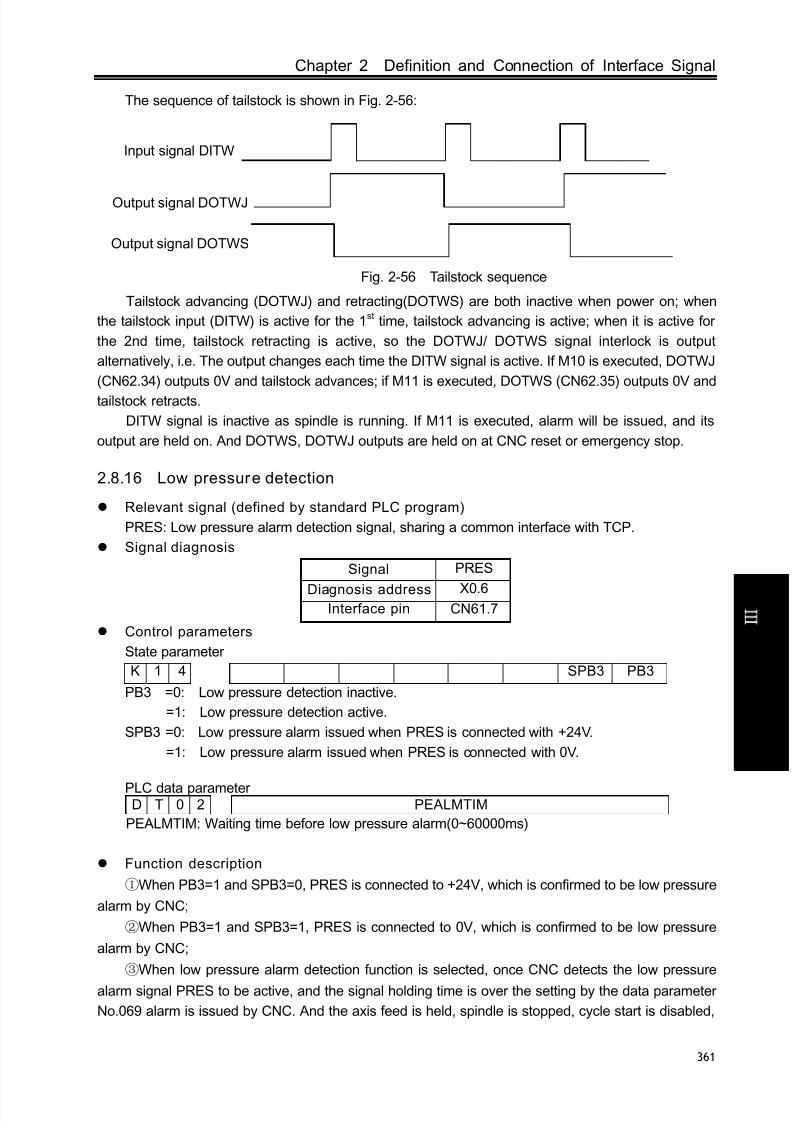
8/17/2019 980TDc CNC Turning Controller User Manual
http://slidepdf.com/reader/full/980tdc-cnc-turning-controller-user-manual 376/461
Chapter 2 Definition and Connection of Interface Signal
361
C onn e c t i on
The sequence of tailstock is shown in Fig. 2-56:
Tailstock advancing (DOTWJ) and retracting(DOTWS) are both inactive when power on; when
the tailstock input (DITW) is active for the 1st time, tailstock advancing is active; when it is active for
the 2nd time, tailstock retracting is active, so the DOTWJ/ DOTWS signal interlock is output
alternatively, i.e. The output changes each time the DITW signal is active. If M10 is executed, DOTWJ
(CN62.34) outputs 0V and tailstock advances; if M11 is executed, DOTWS (CN62.35) outputs 0V and
tailstock retracts.
DITW signal is inactive as spindle is running. If M11 is executed, alarm will be issued, and its
output are held on. And DOTWS, DOTWJ outputs are held on at CNC reset or emergency stop.
2.8.16 Low pressure detection
Relevant signal (defined by standard PLC program)
PRES: Low pressure alarm detection signal, sharing a common interface with TCP.
Signal diagnosis
Signal PRES
Diagnosis address X0.6Interface pin CN61.7
Control parameters
State parameter
K 1 4 SPB3 PB3
PB3 =0: Low pressure detection inactive.
=1: Low pressure detection active.
SPB3 =0: Low pressure alarm issued when PRES is connected with +24V.
=1: Low pressure alarm issued when PRES is connected with 0V.
PLC data parameterD T 0 2 PEALMTIM
PEALMTIM: Waiting time before low pressure alarm(0~60000ms)
Function description
①When PB3=1 and SPB3=0, PRES is connected to +24V, which is confirmed to be low pressure
alarm by CNC;
②When PB3=1 and SPB3=1, PRES is connected to 0V, which is confirmed to be low pressure
alarm by CNC;
③When low pressure alarm detection function is selected, once CNC detects the low pressure
alarm signal PRES to be active, and the signal holding time is over the setting by the data parameter
No.069 alarm is issued by CNC. And the axis feed is held, spindle is stopped, cycle start is disabled,
Input signal DITW
Output signal DOTWJ
Output signal DOTWS
Fig. 2-56 Tailstock sequence
8/17/2019 980TDc CNC Turning Controller User Manual
http://slidepdf.com/reader/full/980tdc-cnc-turning-controller-user-manual 377/461
GSK980TDc Turning CNC System User Manual
362
C onn e c t i on
the alarm may be cancelled by pressing key or cutting off power;
2.8.17 Hydraulic control (only applied to 980TDc-V)
Related signal defined by the standard PLC program)
EXHP: external hydraulic control input signalHPST: hydraulic control output signal
Note: The EXHP input signal can be replaced by key on the operation panel; the diagnosis
address is X0026.4;
Signal diagnosis
Signal HPST
Diagnosis address Y3.1Interface pin CN62.38
Control parameter
PLC state parameter
K 1 4 HPST
PB3 =0: the hydraulic control function is disabled.
=1: the hydraulic control function is enabled.
Function description
① When the hydraulic control function is enabled, pressing can control HPST output to
start the hydraulic motor.
② In non-run, the spindle stop with the speed 0, pressing can disable HPST output.
③ When the hydraulic control function enables and the hydraulic motor is started, the system
alarm, at the time, the spindle cannot rotate.
2.8.18 Safety door detection
Relevant signal
SAGT: For safety door detection, sharing a common interface with SP signal
Signal diagnosis
Signal SAGT
Diagnosis address X0.0
Interface pin CN61.1
Control parameter
PLC status parameters
K 1 4 SGSP SPB4 PB4
PB4 =0: Protection door detection function is invalid;
=1: Protection door detection function is valid;

8/17/2019 980TDc CNC Turning Controller User Manual
http://slidepdf.com/reader/full/980tdc-cnc-turning-controller-user-manual 378/461
Chapter 2 Definition and Connection of Interface Signal
363
C onn e c t i on
SPB4 =0: When SAGT is at low level (disconnect with +24V), the protection door is closed;
=1: When SAGT is at high level (connected with +24V), the protection door is closed;
SGSP =0: Spindle is disabled when the protection door is open;
=1: Spindle is not disabled when the protection door is open;
Function description (defined by standard PLC program)
①When PB4=1, SPB4=0, CNC confirms that the safety door is closed as SAGT is connected
to 0V;
②When PB4=1, SPB4=1, CNC confirms that the safety door is closed as SAGT is connected
to +24V;
③In Auto mode, if CNC detects the safety door is open, alarm is issued as cycle starts;
④In auto running, if CNC detects the safety door is open, the axis feed is held, and alarm is
issued by CNC;
⑤The safety door detection function is only active in Auto mode;
2.8.19 CNC macro variables
Relevant signal
Macro output signal: standard PLC defines 5 macro output interfaces #1100~#1105;
Macro input signal: standard PLC defines 16 macro output interfaces #1000~#1015
Signal diagnosis
Macro variable number #1105 #1104 #1103 #1102 #1101 #1100
Diagnosis address Y3.7 Y3.6 Y3.5 Y3.4 Y3.3 Y3.2
Macro variable number #1007 #1006 #1005 #1004 #1003 #1002 #1001 #1000
Diagnosis address X0.7 X0.6 X0.5 X0.4 X0.3 X0.2 X0.1 X0.0
Macro variable number #1015 #1014 #1013 #1012 #1011 #1010 #1009 #1008
Diagnosis address X1.7 X1.6 X1.5 X1.4 X1.3 X1.2 X1.1 X1.0
Function description (defined by standard PLC program)
U00~U05 signal output may be changed if macro variable #1100~#1105 are assigned. If
they are assigned for “1”, it outputs 0V, if they are assigned for “0”, it turns off their output signals.
Detect the macro variable #1000~#1015 values (input signal state), they may be used for
various processing if combined with other transfer judgment macro code.
2.8.20 External overr ide
Related signals
Type Symbol Interface Address Function Remark
Input
signal
OV1 CN61.8 X0.7 External override 1 The external
feedrate override
switch and the tool
signals T5~T8are multiplexed
OV2 CN61.9 X1.0 External override 2
OV3 CN61.10 X1.1 External override 3
OV4 CN61.11 X1.2 External override 4
8/17/2019 980TDc CNC Turning Controller User Manual
http://slidepdf.com/reader/full/980tdc-cnc-turning-controller-user-manual 379/461
GSK980TDc Turning CNC System User Manual
364
C onn e c t i on
Related parameters
PLC state parameter
K 1 6 ROVI SOVI
ROVI =0: External feedrate override does not inverse.
=1: External feedrate override inverses.
SOVI =0: External feedrate override switch is disabled.
=1: External feedrate override switch is enabled.
Function description
1. When the external feedrate override switch is selected, the button on the panel is disabled.
2. When the external feedrate override switch and the tool signal T5~T8 are multiplexed, and
Yantai, Liuxin Tool Post is selected or the total tool count is more than 4, the external feedrate
override cannot be selected.
3. When the external feedrate override inverses, the system changes the direction of the
override regulation.
2.8.21 External MPG
Related signals
CN31(MPG)PLC
address
Address
characterFunction Remark
5 X6.0 EHDX X MPG
Applied
toPSG-100-05E/L,
ZSSY2080 MPG
6 X6.1 EHDY Y MPG
8 X6.2 EHDZ Z MPG
9 X6.3EMP0 Increment ×1
22 X6.4 EMP1 Increment ×10
23 X6.5 EMP2 Increment ×100
11, 12, 13 GND
14,15 +5V
17,18 +24V
Related parameters
State parameter
0 0 1 MPG
Bit3 =0: Step working mode.
=1: MPG working mode.
PLC status parameters
K 1 6 SINC SINC2
SINC =0: When the system increment is 0.1μ, gear ×1000 in MPG and STEP mode is valid;
=1: When the system increment is 0.1μ, gear ×1000 in MPG and STEP mode is invalid;
SINC2 =0: When the system increment is 1μ, gear ×1000 in MPG and STEP mode is valid;
=1: When the system increment is 1μ, gear ×1000 in MPG and STEP mode is invalid;
Function description
① When SINC is set to 0.1, MPG/STEP mode ×1000-gear selection is disabled. When

8/17/2019 980TDc CNC Turning Controller User Manual
http://slidepdf.com/reader/full/980tdc-cnc-turning-controller-user-manual 380/461
Chapter 2 Definition and Connection of Interface Signal
365
C onn e c t i on
x1000-gearis selected before modifying the parameter, the system automatically changes into
×100-gear;
② When SINC is set to 1, MPG/STEP mode ×1000-gear selection is disabled. When x1000-gearis
selected before modifying the parameter, the system automatically changes into ×100-gear;
③ When the external MPG, its axis selection does not lock, that is, the axis selection of MPG is
disabled, the system changes to the non-axis selection state.
④ When the external MPG axis selection and gear selection input are enabled, the axis selection
on the panel and the gear selection keys are disabled; when the external MPG axis selection and
gear selection input are disabled, the axis selection on the panel and the gear selection keys are
enabled and self-locked.
2.8.22 Tri-color Lamp
Relevant s ignals and function definition (standard PLC program)
Signaltype Symbol Signalinterface Address Function
Outputsignal
CLPY CN62.31 Y2.2Yellow— normal state (non-running,
non-alarm state)
CLPG CN62.32 Y2.3 Green—running state
CLPR CN62.33 Y2.4 Red—alarm state
2.8.23 Gear/tool number display (only applied to 980TDc-V)
Signal diagnosis
Y0025 BIT7 BIT6 BIT5 BIT4 BIT3 BIT2 BIT1 BIT0Corresponding
BCD code
LED1
23
LED1
22
LED1
21
LED1
20
LED0
23
LED0
22
LED0
21
LED0
20
LED 0 displays the current tool number, BIT0~BIT3 of PLC diagnosis number Y25 are BCD code
of the current tool number; LED 1 displays the gear of the current spindle, BIT4~BIT7 of PLC
diagnosis number Y25 are BCD code of the current spindle gear and is shown below:
Function description
① When the tool count is less than 10, the gear and the tool number separately use one LED to
display.
② When the tool count is more than 10, LED 1 displays 10-digit numbers and the LED 0
displays the single digits.
③ When the gear and the tool number are displayed in time-division, that is, the gear instead of
the tool number is firstly display, the tool number instead of the gear is displayed after 1.5S, and the
system executes them like the above cycle.
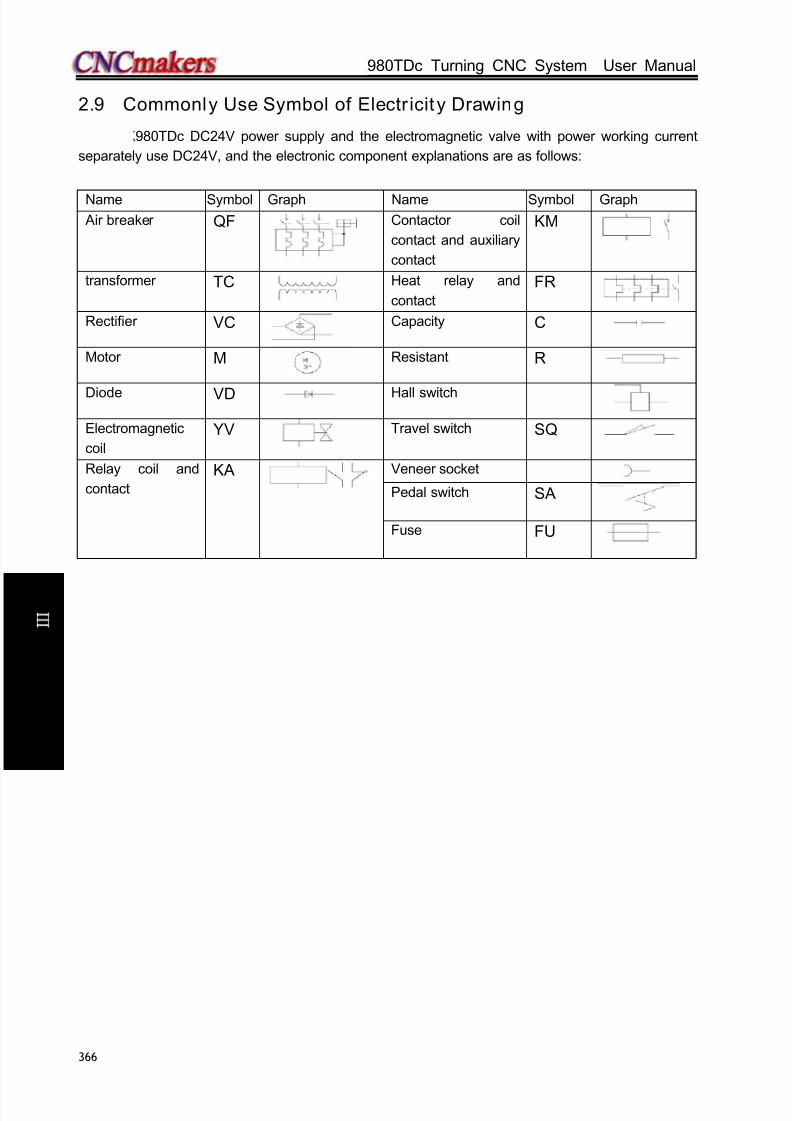
8/17/2019 980TDc CNC Turning Controller User Manual
http://slidepdf.com/reader/full/980tdc-cnc-turning-controller-user-manual 381/461
GSK980TDc Turning CNC System User Manual
366
C onn e c t i on
2.9 Commonly Use Symbol of Electr icit y Drawing
GSK980TDc DC24V power supply and the electromagnetic valve with power working current
separately use DC24V, and the electronic component explanations are as follows:
Name Symbol Graph Name Symbol Graph
Air breaker QF Contactor coil
contact and auxiliary
contact
KM
transformer TC Heat relay and
contact
FR
Rectifier VC Capacity C
Motor M Resistant R
Diode VD Hall switch
Electromagnetic
coil
YV Travel switch SQ
Relay coil and
contact
KA Veneer socket
Pedal switch SA
Fuse FU

8/17/2019 980TDc CNC Turning Controller User Manual
http://slidepdf.com/reader/full/980tdc-cnc-turning-controller-user-manual 382/461
Chapter 3 Parameters
367
V ol um e
C onn e c t i on
CHAPTER 3 PARAMETERS
The CNC bit and data parameters are described in this chapter, various functions can be set by
these parameters. The major parameter data type are listed as follows:Data type Range
(1) Bit
8 bit, 0 or 1(2) Bit axis
(3) Bit spindle
(4) Word
See relevant
parameters for
details
(5) Word axis
(6) Word spindle
Note: if the data type is not specified, the type is bit or word.
3.1 Parameter Descript ion (by sequence)
3.1.1 Bit parameter
The state parameter is expressed as follows:
Parameter No. BIT7 BIT6 BIT5 BIT4 BIT3 BIT2 BIT1 BIT0
0 0 1 *** *** *** ACS MPG PROG ISC INI
Bit4 1: Spindle analog voltage control
0: Spindle switching volume control
Bit3 1: MPG mode
0: Step mode
Bit2 1: Programming by radius
0: Programming by diameterBit1 1: IS-C incremental system
0: IS-B incremental system
Increment system Least input increment,
least command increment
Abbreviation
0 0.001mm,0.0001inch IS-B
1 0.0001mm, 0.00001inch IS-C
Bit0 1: Inch input
0: Metric input
0 0 2 CLK *** *** LIFJ MDITL LIFC TNRC TLIF
Bit7 1: Show clock

8/17/2019 980TDc CNC Turning Controller User Manual
http://slidepdf.com/reader/full/980tdc-cnc-turning-controller-user-manual 383/461
GSK980TDc Turning CNC System User Manual
368
V ol um e
C onn e c t i on
0: Conceal clock
Bit4 1: Tool life management group skip active
0: Tool life management group skip inactive
Bit3 1: Tool life management active in MDI mode
0: Tool life management inactive in MDI mode
Bit2 1: Tool life counting type 2, by times
0: Tool life counting type 1, by times
Bit1 1: Tool nose radius offset active
0: Tool nose radius offset inactive
Bit0 1: Tool life management active
0: Tool life management inactive
0 0 3 *** *** PCOMP TCOMP *** *** *** OIM
Bit5 1: Pitch error offset active
0: Pitch error offset inactive
Bit4 1: Tool offset by coordinate offset
0: Tool offset by move
Bit0 1: Offset automatically change in metric and inch conversion
0: Offset not change in metric and inch conversion
0 0 4 ABOT RDRN DECI ORC *** *** PROD SCW
Bit7 1: do not memorize absolute coordinate in power-down
0: memorize the absolute coordinate in power-down
Bit6 1: G00 is rapid traverse speed in dry run mode
0: G00 is manual feedrate in dry run modeBit5 1: DEC signal is high level for machine zero return
0: DEC signal is low level for machine zero return
Bit4 1: Tool offset by radius
0: Tool offset by diameter
Bit1 1: Relative position for programming in POSITION page
0: Relative position involving offset in POSITION page
Bit0 1: Inch system for min. code unit, active after repowering
0: Metric system for min. code unit, active after repowering
0 0 5 *** *** SMAL M30 *** POSRE PPD PCMD
Bit 5 1: Manual spindle gear change during the execution of S code;
0: Automatic spindle gear change during the execution of S code;
Bit 4 1: Cursor returns to the head of the program after the execution of M30;
0: Cursor does not return to the head of the program after the execution of M30;
Bit 2: 1: Position recording signal PRC is used during tool setting;
0: Position recording signal PRC is not used during tool setting;
Bit 1: 1: G50 sets relative coordinate value;
0: G50 does not set relative coordinate value;
Bit 0: 1: Axial output wave is pulse;
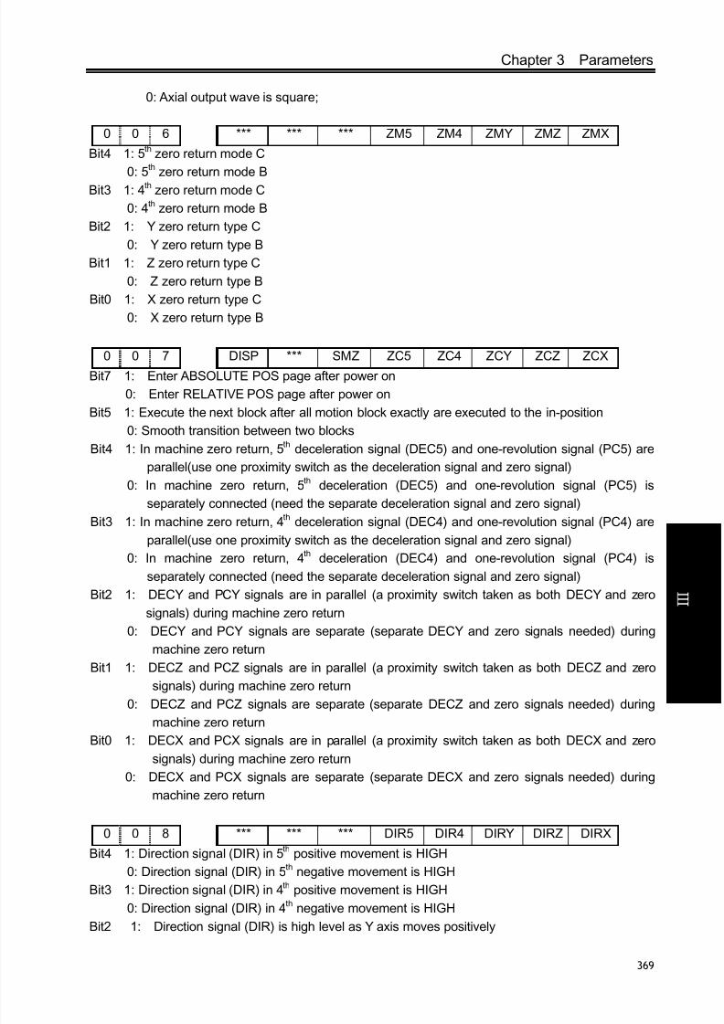
8/17/2019 980TDc CNC Turning Controller User Manual
http://slidepdf.com/reader/full/980tdc-cnc-turning-controller-user-manual 384/461
Chapter 3 Parameters
369
V ol um e
C onn e c t i on
0: Axial output wave is square;
0 0 6 *** *** *** ZM5 ZM4 ZMY ZMZ ZMX
Bit4 1: 5th zero return mode C
0: 5th zero return mode B
Bit3 1: 4th zero return mode C
0: 4th zero return mode B
Bit2 1: Y zero return type C
0: Y zero return type B
Bit1 1: Z zero return type C
0: Z zero return type B
Bit0 1: X zero return type C
0: X zero return type B
0 0 7 DISP *** SMZ ZC5 ZC4 ZCY ZCZ ZCXBit7 1: Enter ABSOLUTE POS page after power on
0: Enter RELATIVE POS page after power on
Bit5 1: Execute the next block after all motion block exactly are executed to the in-position
0: Smooth transition between two blocks
Bit4 1: In machine zero return, 5th deceleration signal (DEC5) and one-revolution signal (PC5) are
parallel(use one proximity switch as the deceleration signal and zero signal)
0: In machine zero return, 5th deceleration (DEC5) and one-revolution signal (PC5) is
separately connected (need the separate deceleration signal and zero signal)
Bit3 1: In machine zero return, 4th deceleration signal (DEC4) and one-revolution signal (PC4) are
parallel(use one proximity switch as the deceleration signal and zero signal)0: In machine zero return, 4th deceleration (DEC4) and one-revolution signal (PC4) is
separately connected (need the separate deceleration signal and zero signal)
Bit2 1: DECY and PCY signals are in parallel (a proximity switch taken as both DECY and zero
signals) during machine zero return
0: DECY and PCY signals are separate (separate DECY and zero signals needed) during
machine zero return
Bit1 1: DECZ and PCZ signals are in parallel (a proximity switch taken as both DECZ and zero
signals) during machine zero return
0: DECZ and PCZ signals are separate (separate DECZ and zero signals needed) during
machine zero return
Bit0 1: DECX and PCX signals are in parallel (a proximity switch taken as both DECX and zero
signals) during machine zero return
0: DECX and PCX signals are separate (separate DECX and zero signals needed) during
machine zero return
0 0 8 *** *** *** DIR5 DIR4 DIRY DIRZ DIRX
Bit4 1: Direction signal (DIR) in 5th positive movement is HIGH
0: Direction signal (DIR) in 5th negative movement is HIGH
Bit3 1: Direction signal (DIR) in 4
th
positive movement is HIGH0: Direction signal (DIR) in 4th negative movement is HIGH
Bit2 1: Direction signal (DIR) is high level as Y axis moves positively

8/17/2019 980TDc CNC Turning Controller User Manual
http://slidepdf.com/reader/full/980tdc-cnc-turning-controller-user-manual 385/461
GSK980TDc Turning CNC System User Manual
370
V ol um e
C onn e c t i on
0: Direction signal (DIR) is low level as Y axis moves negatively
Bit1 1: Direction signal (DIR) is high level as Z axis moves positively
0: Direction signal (DIR) is high level as Z axis moves negatively
Bit0 1: Direction signal (DIR) is high level as X axis moves positively
0: Direction signal (DIR) is high level as X axis moves negatively
0 0 9 *** *** *** 5ALM 4ALM YALM ZALM XALM
Bit4 1: 5th alarm signal (ALM5) is LOW alarm
0: 5th alarm signal (ALM5) is HIGH alarm
Bit3 1: 4th alarm signal (ALM5) is LOW alarm
0: 4th alarm signal (ALM5) is HIGH alarm
Bit2 1: Y alarm signal (YALM) is low level alarm
0: Y alarm signal (YALM) is high level alarm
Bit1 1: Z alarm signal (ZALM) is low level alarm
0: Z alarm signal (ZALM) is high level alarm
Bit0 1: X alarm signal (XALM) signal is low level alarm
0: X alarm signal (XALM) signal is high level alarm
0 1 0 *** *** *** CPF5 CPF4 CPF3 CPF2 CPF1
Bit0~ Bit4: Pulse frequency setting values of backlash offset (by BCD code)
The set frequency =(setting value+1) Kpps
CPF5 CPF4 CPF3 CPF2 CPF1Set frequency
(Kpps)
0 0 0 0 0 1
0 0 0 0 1 20 0 0 1 0 3
0 0 0 1 1 4
0 0 1 0 0 5
0 0 1 0 1 6
0 0 1 1 0 7
0 0 1 1 1 8
0 1 0 0 0 9
0 1 0 0 1 10
0 1 0 1 0 11
0 1 0 1 1 12
0 1 1 0 0 13
0 1 1 0 1 14
0 1 1 1 0 15
0 1 1 1 1 16
1 0 0 0 0 17
1 0 0 0 1 18
1 0 0 1 0 19
1 0 0 1 1 20
1 0 1 0 0 211 0 1 0 1 22

8/17/2019 980TDc CNC Turning Controller User Manual
http://slidepdf.com/reader/full/980tdc-cnc-turning-controller-user-manual 386/461
Chapter 3 Parameters
371
V ol um e
C onn e c t i on
1 0 1 1 0 23
1 0 1 1 1 24
1 1 0 0 0 25
1 1 0 0 1 26
1 1 0 1 0 27
1 1 0 1 1 28
1 1 1 0 0 29
1 1 1 0 1 30
1 1 1 1 0 31
1 1 1 1 1 32
0 1 1 BDEC BD8 *** *** NORF ZNIK *** ***
Bit7 1: Backlash offset type B, the offset data are output by ascending or descending type and the
set frequency is inactive;
0: Backlash offset type A, the offset data are output by the set frequency (by bit parameterNo.010) or 1/8 of it.
Bit6 1: Backlash offset is done by the 1/8 of the set frequency
0: Backlash offset is done by the set frequency
Bit3 1: Manual machine zero return inactive
0: Manual machine zero return active
Bit2 1: Direction key locked during zero return, homing continues to end by pressing direction key
once;
0: Direction key unlocked, which is held on during zero return
0 1 2 APRS WSFT DOFSI *** EAL *** EBCL ISOT
Bit7 1: Automatic ABSOLUTE set after reference return,;
0: ABSOLUTE not automatically set after reference return
Bit6 1: Workpiece coordinate offset active, defined by offset No.000
0: Workpiece coordinate offset inactive
Bit5 1: Trial tool setting active
0: Trial tool setting inactive
Bit3 1: Program editing allowed during CNC alarming
0: Program editing unallowed during CNC alarming
Bit1 1: Program end sign EOB displayed for “;”
0: Program end sign EOB displayed for “*”
Bit0 1: Prior to machine zero return after power on, manual rapid traverse active
0: Prior to machine zero return after power on, manual rapid traverse inactive
0 1 2 APRS WSFT DOFSI *** EAL *** *** ISOT
Bit7 1: Automatic ABSOLUTE set after reference return,;
0: ABSOLUTE not automatically set after reference return
Bit6 1: Workpiece coordinate offset active, defined by offset No.000
0: Workpiece coordinate offset inactive
Bit5 1: Trial tool setting active0: Trial tool setting inactive
Bit3 1: Program editing allowed during CNC alarming

8/17/2019 980TDc CNC Turning Controller User Manual
http://slidepdf.com/reader/full/980tdc-cnc-turning-controller-user-manual 387/461
GSK980TDc Turning CNC System User Manual
372
V ol um e
C onn e c t i on
0: Program editing unallowed during CNC alarming
Bit0 1: Prior to machine zero return after power on, manual rapid traverse active
0: Prior to machine zero return after power on, manual rapid traverse inactive
0 1 3 *** *** *** HW5 HW4 HWY HWZ HWX
Bit4 1: Coordinates increase in 5th MPG (CCW) rotation
0: Coordinates increase in 5th MPG (CW) rotation
Bit3 1: Coordinates increase in 4th MPG (CCW) rotation
0: Coordinates increase in 4th MPG (CW) rotation
Bit2 1: Coordinates increase in Y MPG (CCW) rotation
0: Coordinates increase in Y MPG (CW) rotation
Bit1 1: Coordinates increase in Z MPG (CCW) rotation
0: Coordinates increase in Z MPG (CW) rotation
Bit0 1: Coordinates increase in X MPG (CCW) rotation
0: Coordinates increase in X MPG (CW) rotation
0 1 4 *** *** *** ZRS5 ZRS4 ZRSY ZRSZ ZRSX
Bit 4, Bit3, Bit2, Bit1, Bit0
1: 5th, 4th, Y, Z, X have the machine zeroes. The system needs to check the deceleration signal
and zero signal in executing the machine zero return
0: 5th, 4th, Y, Z, X have no machine zeroes. The system does not check the deceleration signal
and zero signal till it returns to the zero of machine coordinate in executing the machine zero return
0 1 7 SCRD *** RSCD *** TSD QNI TSL TS1
Bit7 1:Coordinate system is stored before power-off;
0: Coordinate system is not stored before power-off; the default system is set by G54 after
power-on;
Bit5 1: Coordinate system is set by G54 after reset;
0: Coordinate system is not changed after reset;
Bit3 1: Movement direction discrimination is valid during offset measurement 4 point input;
0: Movement direction discrimination is invalid during offset measurement 4 point input;
Bit2 1: Tool offset number is set through G signal;
0: Tool offset number is set through the current cursor;
Bit1 1 Tool offset measurement detection signal is valid at low level;0: Tool offset measurement detection signal is valid at high level;
Bit0 1:Tool offset automatic measurement detection signal 1 point input;
0: Tool offset automatic measurement detection signal 4-point input;
1 7 2 *** MST MSP MOT ESP *** LZR ***
Bit6 1: External cycle start signal (ST) inactive, it is not the cycle start switch and can be defined
by macro code (#1014)
0: External cycle start signal (ST) active
Bit5 1: External SP signal inactive, and it is not the stop switch and can be defined by macro
code.( #1015)
0: External SP signal active with external dwell switch needed, otherwise CNC shows

8/17/2019 980TDc CNC Turning Controller User Manual
http://slidepdf.com/reader/full/980tdc-cnc-turning-controller-user-manual 388/461
Chapter 3 Parameters
373
V ol um e
C onn e c t i on
“Stop”.mailto:M@SP=1
Bit4 1: Not detect software stroke limit
0: Detect software stroke limit
Bit3 1: Emergency stop inactive
0: Emergency stop active
Bit1 1: Software limit is inactive after power-on and before machine zero return;
0: Software limit is active after power-on and before machine zero return;
1 7 4 *** *** *** *** KEY1 *** *** ***
Bit3 1: Program switch ON at power on
0: Program switch OFF at power on
1 7 5 SPFD SAR THDA VAL5 VAL4 VALY VALZ VALX
Bit7 1: In cutting feed, do not permit the spindle stopping rotation; the spindle stops, the feed also
stops when the system appears No.404 alarm cutting
0: In cutting feed, permit the spindle stops rotation; the spindle stops rotation, but the feeddoes not stop
Bit6 1: Detect spindle SAR signal prior to cutting
0: Not detect spindle SAR signal prior to cutting
Bit5 1: Thread machining is the exponential acceleration/deceleration
0: Thread machining is the linear acceleration/deceleration
Bit4 1: 5th movement key is _positive, is _negative
0: 5th movement key is _positive, is _negative
Bit3 1: 4th movement key is positive, is negative
0: 4th movement key is positive, is negative
Bit2 1: Y movement key is positive, is negative
0: Y movement key is positive, is negative
Bit1 1: movement key is positive, is negative
0: Z movement key is positive, is negative
Bit0 1: X movement key is positive, is negative
0: X movement key is positive, is negative
1 8 0 NAT *** *** *** *** *** *** SPOS
Bit7 1: Function ATAN, ASIN range is 90.0~270.0;
0: Function ATAN, ASIN range is -90.0~90.0
Bit0 1: DIS TO GO displayed in POS&PRG page
0: RELATIVE POS displayed in POS&PRG page
1 8 1 RLC MRC ZCL *** MCL *** *** LCNMD
Bit7 1: G52 local coordinate system is cancelled after reset;
0: G52 local coordinate system is not cancelled after reset;
Bit6 1: G52 local coordinate system is cancelled after the execution of M30, M02;
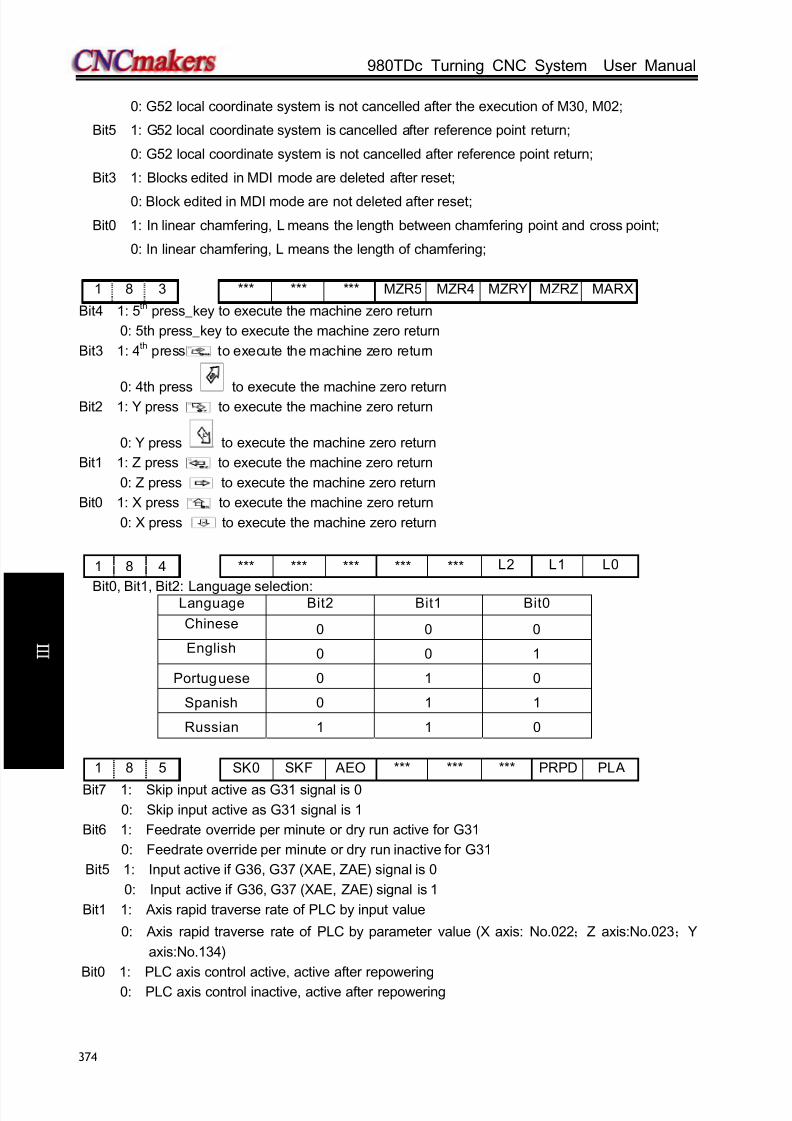
8/17/2019 980TDc CNC Turning Controller User Manual
http://slidepdf.com/reader/full/980tdc-cnc-turning-controller-user-manual 389/461
GSK980TDc Turning CNC System User Manual
374
V ol um e
C onn e c t i on
0: G52 local coordinate system is not cancelled after the execution of M30, M02;
Bit5 1: G52 local coordinate system is cancelled after reference point return;
0: G52 local coordinate system is not cancelled after reference point return;
Bit3 1: Blocks edited in MDI mode are deleted after reset;
0: Block edited in MDI mode are not deleted after reset;
Bit0 1: In linear chamfering, L means the length between chamfering point and cross point;
0: In linear chamfering, L means the length of chamfering;
1 8 3 *** *** *** MZR5 MZR4 MZRY MZRZ MARX
Bit4 1: 5th press_key to execute the machine zero return
0: 5th press_key to execute the machine zero return
Bit3 1: 4th press to execute the machine zero return
0: 4th press to execute the machine zero returnBit2 1: Y press to execute the machine zero return
0: Y press to execute the machine zero return
Bit1 1: Z press to execute the machine zero return
0: Z press to execute the machine zero return
Bit0 1: X press to execute the machine zero return
0: X press to execute the machine zero return
1 8 4 *** *** *** *** *** L2 L1 L0
Bit0, Bit1, Bit2: Language selection:Language Bit2 Bit1 Bit0
Chinese 0 0 0
English 0 0 1
Portuguese 0 1 0
Spanish 0 1 1
Russian 1 1 0
1 8 5 SK0 SKF AEO *** *** *** PRPD PLA
Bit7 1: Skip input active as G31 signal is 0
0: Skip input active as G31 signal is 1
Bit6 1: Feedrate override per minute or dry run active for G31
0: Feedrate override per minute or dry run inactive for G31
Bit5 1: Input active if G36, G37 (XAE, ZAE) signal is 0
0: Input active if G36, G37 (XAE, ZAE) signal is 1
Bit1 1: Axis rapid traverse rate of PLC by input value
0: Axis rapid traverse rate of PLC by parameter value (X axis: No.022;Z axis:No.023;Y
axis:No.134)
Bit0 1: PLC axis control active, active after repowering
0: PLC axis control inactive, active after repowering

8/17/2019 980TDc CNC Turning Controller User Manual
http://slidepdf.com/reader/full/980tdc-cnc-turning-controller-user-manual 390/461
Chapter 3 Parameters
375
V ol um e
C onn e c t i on
1 8 6 RTORI SRS *** *** *** RTCRG *** ***
Bit7 1: In executing M29, the spindle executes the machine zero return
0: In executing M29, the spindle does not execute the machine zero return
Bit6 1: The spindle selection signal is RGTSPn in the multiple spindle rigid tapping
0: The spindle selection signal is SWSn in the multiple spindle rigid tapping
Bit2 1: In rigid tapping cancel, do not wait for G61.0 to be 0 in executing the next block
0: In rigid tapping cancel, wait for G61.0 to be 0 in executing the next block
1 8 7 YIS1Y Y IS0 RCSY *** *** *** ROSY ROTY
BIT7,BIT6: Set Y incremental system,
00: consistent with the incremental system of the system,
01: IS-A,10: IS-B;11: IS-C.
Bit5 1: Y Cs function is valid/invalid(power-on again)
0: Y Cs function is valid/invalid(power-on again)
Bit1,Bit0 : 00 : sets Y to be linear,01 : sets Y to be rotary axis(A type),
11 : sets Y to be rotary axis(B type),
10: sets Y to be invalid
1 8 7 YIS1Y Y IS0 RCSY *** *** *** ROSY ROTY
[Data type]: Bit axis
BIT7, BIT6: Set the increment system of all axes;
00: Same with the original increment system; 01: IS-A; 10: IS-B; 11: IS-C;
Bit5 1: Cs function of auxiliary axis is enabled (needs to re-power on)
0: Cs function of auxiliary axis is not enabled (needs to re-power on)
Bit1, Bit0: 00: Set auxiliary axis as linear axis; 01: Set auxiliary axis as rotary axis (A type); 11:
Set auxiliary axis as rotary axis (B type); 10: Auxiliary axis is disabled;
Note: This parameter is invalid to X, Z axes.
1 8 8 *** RRTY *** *** *** RRLY RABY ROAY
[Data type]: Bit axis
Bit6 1: When Y is the rotary axis, the zero return uses D mode
0: When Y is the rotary axis, the zero return uses A, B, C mode
Bit2 1: When Y is the rotary axis, the relative coordinate cycle function is valid
0: When Y is the rotary axis, the relative coordinate cycle function is invalid
Bit1 1: Y rotates according to the symbol when it is the rotary axis
0: Y rotates contiguously when it is the rotary axis
Bit0 1: The absolute coordinate cycle function is valid when Y is the rotary axis
0: The absolute coordinate cycle function is valid when Y is the rotary axis
1 9 6 MSI CSS *** MSEN *** *** *** ***
Bit7 1: The multiple spindle control B0: The multiple spindle control A
Bit6 1: Cs control of each axis is executed in the multiple spindle control

8/17/2019 980TDc CNC Turning Controller User Manual
http://slidepdf.com/reader/full/980tdc-cnc-turning-controller-user-manual 391/461
GSK980TDc Turning CNC System User Manual
376
V ol um e
C onn e c t i on
0: Cs control of only the 1st spindle is executed in the multiple spindle control
Bit4 1: The multiple spindle control is enabled
0: The multiple spindle control is disabled
2 0 3 *** *** *** ABP5 ABP4 ABPY ABPZ ABPX
Bit4 1: 5th pulse outputs based on the two-phase quadrature
0: 5th pulse outputs based on (pulse+direction)
Bit3 1: 4th pulse outputs based on the two-phase quadrature
0: 4th pulse outputs based on (pulse+direction)
Bit2 1: Y pulse outputs based on the two-phase quadrature
0: Y pulse outputs based on (pulse+direction)
Bit1 1: Z pulse outputs based on the two-phase quadrature
0: Z pulse outputs based on (pulse+direction)
Bit0 1: X pulse outputs based on the two-phase quadrature
0: X pulse outputs based on (pulse+direction)
3.1.2 Data parameter
0 1 5 CMRn
[Data type] Word axis
[Data meaning] Pulse frequency multiplication coefficient
[Data range] 1~32767
0 1 6 CMDn
[Data type] Word axis
[Data meaning] Pulse frequency division coefficient;
[Data range] 1~32767
Explanation: Formula of electric gear ratio::
D
M
Z
Z
L
C
CMD
CMR*
**4 δ =
Δ: Least command increment;ZM: Teeth number of pulley on leading screw side;C: Motor encoder line number;
ZD Teeth number of pulley on motor side;L: Screw lead
0 1 9 THDCH
[Data meaning] Run-out length in threading
[Data range] 0~225
Thread run-out width= THDCH×0.1×screw lead
0 2 1 PSANGNT
[Data type] Word spindle
[Data meaning] Voltage offset value when spindle max. speed analog voltage output is 10V
[Data unit] mV
[Data range] -2000~2000(Unit: mV)
0 2 2 RPDFn
[Data type] Word axis

8/17/2019 980TDc CNC Turning Controller User Manual
http://slidepdf.com/reader/full/980tdc-cnc-turning-controller-user-manual 392/461
Chapter 3 Parameters
377
V ol um e
C onn e c t i on
[Data meaning] Maximum rapid traverse rate of all axes
[Data unit] Setting unit Data unit
Metric machine mm/min
Inch machine0.1inch/min
[Data range] 10~99999999
0 2 3 RPDFZ
[Data type] Word axis
[Data meaning] Acceleration/deceleration time constant during rapid traverse
[Data unit]
Setting unit Data unit
Metric machine mm/min
Inch machine 0.1inch/min
[Data range] 0~4000
0 2 6 THRDT
[Data meaning] ACC&DEC time constant of short axis in thread run-out
[Data unit] ms
[Data range] 0~4000
0 2 7 FEDMX
Data meaning] Upper limits of X, Z feedrate
[Data unit]
Setting unit Data unit
Metric machine mm/min
Inch machine 0.1inch/min
[Data range]
IS-B IS-C
Metric machine 10~15000 10~15000
Inch machine 5~5800 10~5800
0 2 8 THDFL
[Data meaning] X, Z initial speed in threading (mm/min)
[Data unit]
Setting unit Data unit
Metric machine mm/min
Inch machine 0.1inch/min
[Data range]
IS-B IS-C
Metric
machine 6~8000 6~8000
Inch machine 3~3000 3~3000

8/17/2019 980TDc CNC Turning Controller User Manual
http://slidepdf.com/reader/full/980tdc-cnc-turning-controller-user-manual 393/461
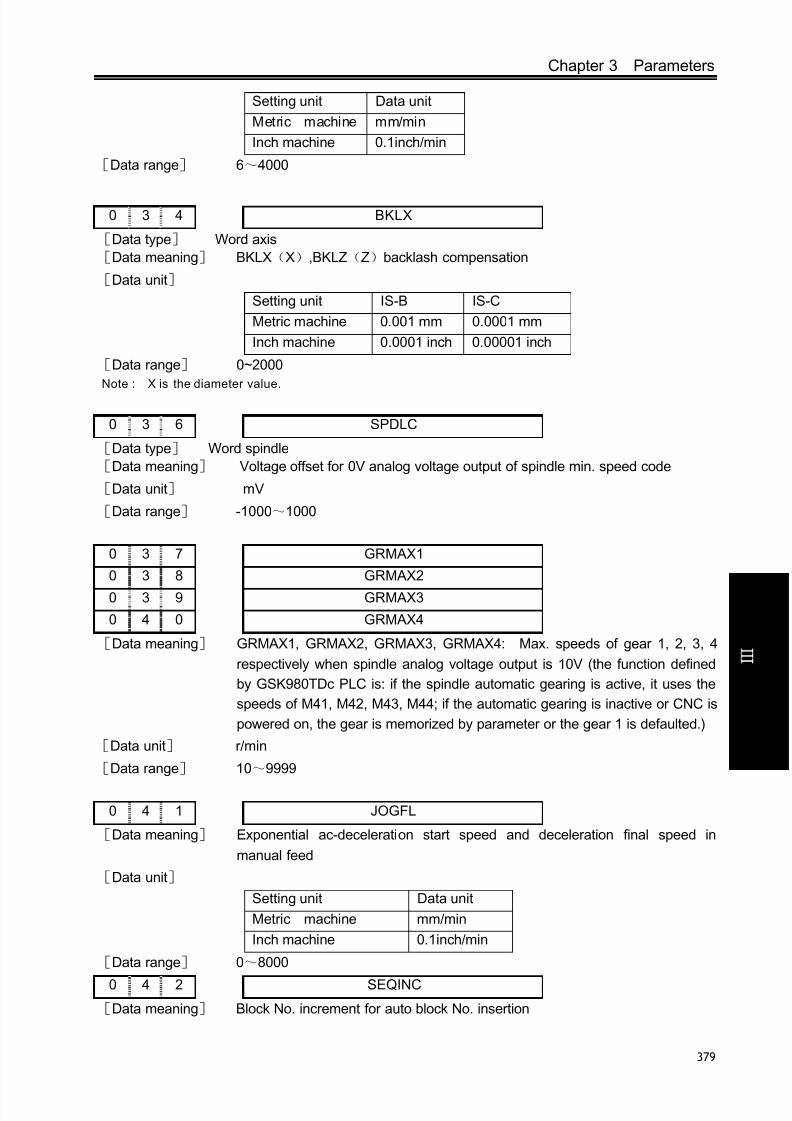
8/17/2019 980TDc CNC Turning Controller User Manual
http://slidepdf.com/reader/full/980tdc-cnc-turning-controller-user-manual 394/461
Chapter 3 Parameters
379
V ol um e
C onn e c t i on
Setting unit Data unit
Metric machine mm/min
Inch machine 0.1inch/min
[Data range] 6~4000
0 3 4 BKLX
[Data type] Word axis
[Data meaning] BKLX(X),BKLZ(Z)backlash compensation
[Data unit]
Setting unit IS-B IS-C
Metric machine 0.001 mm 0.0001 mm
Inch machine 0.0001 inch 0.00001 inch
[Data range] 0~2000
Note : X is the diameter value.
0 3 6 SPDLC
[Data type] Word spindle
[Data meaning] Voltage offset for 0V analog voltage output of spindle min. speed code
[Data unit] mV
[Data range] -1000~1000
0 3 7 GRMAX1
0 3 8 GRMAX2
0 3 9 GRMAX3
0 4 0 GRMAX4
[Data meaning] GRMAX1, GRMAX2, GRMAX3, GRMAX4: Max. speeds of gear 1, 2, 3, 4
respectively when spindle analog voltage output is 10V (the function defined
by GSK980TDc PLC is: if the spindle automatic gearing is active, it uses the
speeds of M41, M42, M43, M44; if the automatic gearing is inactive or CNC is
powered on, the gear is memorized by parameter or the gear 1 is defaulted.)
[Data unit] r/min
[Data range] 10~9999
0 4 1 JOGFL
[Data meaning] Exponential ac-deceleration start speed and deceleration final speed in
manual feed
[Data unit]
Setting unit Data unit
Metric machine mm/min
Inch machine 0.1inch/min
[Data range] 0~8000
0 4 2 SEQINC
[Data meaning] Block No. increment for auto block No. insertion

8/17/2019 980TDc CNC Turning Controller User Manual
http://slidepdf.com/reader/full/980tdc-cnc-turning-controller-user-manual 395/461
GSK980TDc Turning CNC System User Manual
380
V ol um e
C onn e c t i on
[Data range] 1~100
0 4 3 LOWSP
[Data meaning] (G96) Spindle min. speed under the constant surface speed control
[Data unit] r/min
[Data range] 0~9999
0 4 4 BRATE0
[Data meaning] Serial communication baud rate,
[Data unit] bit/s
[Data range] 1200,2400,4800,9600,19200,38400 57600 115200
0 4 5 LT1X1
0 4 6 LT1Z1
[Data type] Word axis
[Data meaning] LT1X1(X),LT1Z1(Z)positive max. travel,LT1X2(X),LT1Z2(Z)negative
max. travel
[Data unit]
Setting unit IS-B IS-C
Metric machine 0.001 mm 0.0001 mm
Inch machine 0.0001 inch 0.00001 inch
[Data range] -99999999~99999999
Note: If the BIT2 of the parameter No.001 is set for diameter, the X axis value is specified by diameter; if for
radius, the X axis value is specified by radius.
0 4 7 PRSn
[Data type] Word axis
[Data meaning] Setting value of absolute coordinate after machine zero return
[Data unit]
Setting unit IS-B IS-C
Metric input 0.001 mm 0.0001 mm
Inch input 0.0001 inch 0.00001 inch
[Data range] -99999999~99999999
0 5 1 MRCCD
[Data meaning] Each feeding for G71, G72 rough turning cycle, which may also be changed by
program code in auto running.
[Data unit]
Setting unit IS-B IS-C
Metric input 0.001 mm 0.0001 mm
Inch input 0.0001 inch 0.00001 inch
[Data range]
IS-B IS-C

8/17/2019 980TDc CNC Turning Controller User Manual
http://slidepdf.com/reader/full/980tdc-cnc-turning-controller-user-manual 396/461
Chapter 3 Parameters
381
V ol um e
C onn e c t i on
Metric input 1~99999 1~999999
Inch input 1~99999 1~999999
0 5 2 MRCDT
[Data meaning] Each retraction for G71, G72 rough turning cycle, which may also be changedby program code in auto running.
[Data unit]
Setting unit IS-B IS-C
Metric input 0.001 mm 0.0001 mm
Inch input 0.0001 inch 0.00001 inch
[Data range] 0~99999
0 5 3 PECSCX0
[Data meaning] X axis rough turning retraction in G73, which may also be changed by programcode in auto running.
[Data unit]
Setting unit IS-B IS-C
Metric input 0.001 mm 0.0001 mm
Inch input 0.0001 inch 0.00001 inch
[Data range] -9999999~9999999
0 5 4 PECSCZ
[Data meaning] Z axis rough turning retraction in G73, which may also be changed by programcode in auto running
[Data unit]
Setting unit IS-B IS-C
Metric input 0.001 mm 0.0001 mm
Inch input 0.0001 inch 0.00001 inch
[Data range] -9999999~9999999
0 5 5 PATIM
[Data meaning] Cycle times of G73, which may also be changed by program code in auto
running
[Data unit] times
[Data range] 1~9999
0 5 6 GROVE
[Data meaning] Retraction value of Z axis in G74; retraction value of X axis in G75; a specified
value in program during automatic running can also change the setting of this
parameter;
[Data unit] Setting unit IS-B IS-C
Metric input 0.001 mm 0.0001 mm

8/17/2019 980TDc CNC Turning Controller User Manual
http://slidepdf.com/reader/full/980tdc-cnc-turning-controller-user-manual 397/461
GSK980TDc Turning CNC System User Manual
382
V ol um e
C onn e c t i on
Inch input 0.0001 inch 0.00001 inch
[Data range] 0~99999
0 5 7 THRPT
[Data meaning] Repetitions of G76 finish machining, which may also be changed by program
code in auto running[Data unit] times
[Data range] 1~99
0 5 8 THANG
[Data meaning] Tool nose angle of G76 cycle, which may also be changed by program code in
auto running
[Data unit] deg
[Data range] 0~99
0 5 9 THCLM
[Data meaning] Min. cut depth of G76 cycle, which may also be changed by program code in
auto running
[Data unit]
Setting unit IS-B IS-C
Metric input 0.001 mm 0.0001 mm
Inch input 0.0001 inch 0.00001 inch
[Data range]
IS-B IS-CMetric input 0~99999 0~999999
Inch input 0~99999 0~999999
0 6 0 THDFN
[Data meaning] Finish allowance of G76, which may also be changed by program code in auto
running
[Data unit]
Setting unit IS-B IS-C
Metric input 0.001 mm 0.0001 mmInch input 0.0001 inch 0.00001 inch
[Data range]
IS-B IS-C
Metric input 0~99999 0~999999
Inch input 0~99999 0~999999
0 6 7 SFTREV
[Data type] Word spindle
[Data meaning] Output voltage of spindle gearing
[Data unit] mV

8/17/2019 980TDc CNC Turning Controller User Manual
http://slidepdf.com/reader/full/980tdc-cnc-turning-controller-user-manual 398/461
Chapter 3 Parameters
383
V ol um e
C onn e c t i on
[Data range] 0~10000
0 6 8 SJOGREV
[Data type] Word spindle
[Data meaning] spindle speed in manual (MPG) mode
[Data unit] r/min
[Data range] 0~3000
0 7 0 ENCODER_CNT
[Data type] Word spindle
[Data meaning] Spindle encoder pulses
[Data unit] line/revolution
[Data range] 100~5000
0 7 1 RESET_TIME
[Data meaning] Output time of reset signal
[Data unit] ms
[Data range] 16~4080
0 7 2 SAR_DELEY
[Data meaning] Delay detecting time of SAR signal
[Data unit] ms
[Data range] 0~4080
0 7 3 SPMOTORMAX
[Data type] Word spindle
[Data meaning] Max. spindle motor clamping speed, setting value=(max. spindle motor
clamping speed/max. spindle motor speed) ×4095
[Data unit] r/min
[Data range] 0~4095
Setting value =(max. clamp speed of spindle/max. speed of spindle motor )×4095.
0 7 4 SPMOTORMIN
[Data meaning] Min. spindle motor clamping speed, setting value=(min. spindle motor
clamping speed/max. spindle motor speed) ×4095
[Data unit] r/min
[Data range] 0~4095
Setting value =(min. clamping speed of spindle motor/max. speed of spindle motor )×4095
0 7 5 SPSPEEDLIMIT
[Data type] Word spindle[Data meaning] Maximum spindle rev speed(0~6000r/min)[0:unlimited]
[Data unit] r/min
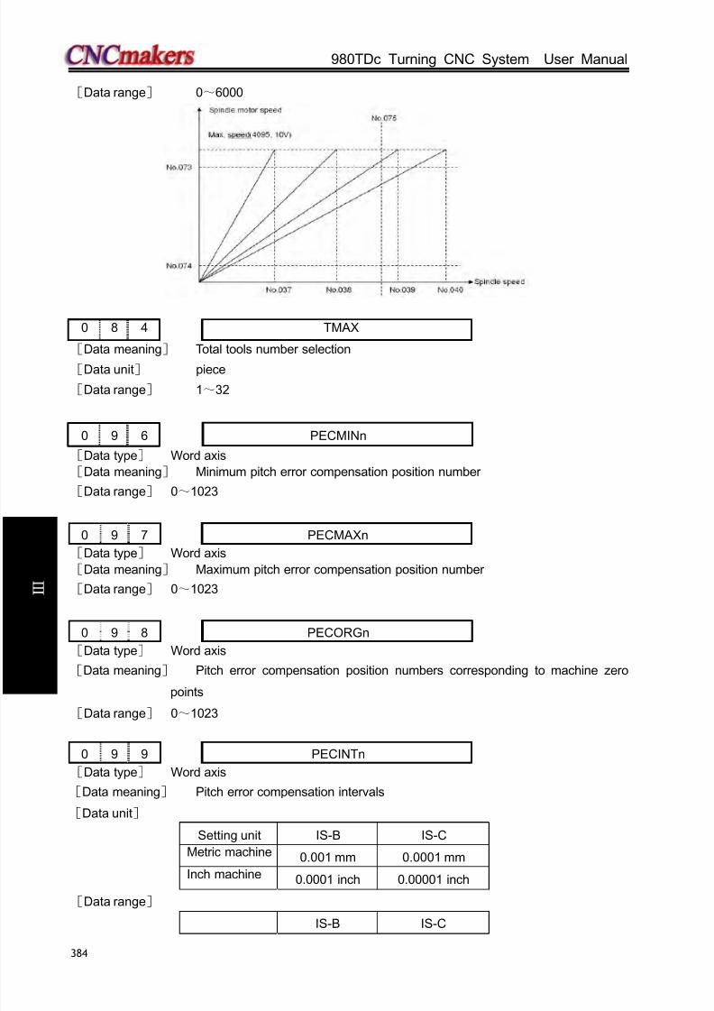
8/17/2019 980TDc CNC Turning Controller User Manual
http://slidepdf.com/reader/full/980tdc-cnc-turning-controller-user-manual 399/461
GSK980TDc Turning CNC System User Manual
384
V ol um e
C onn e c t i on
[Data range] 0~6000
0 8 4 TMAX
[Data meaning] Total tools number selection[Data unit] piece
[Data range] 1~32
0 9 6 PECMINn
[Data type] Word axis
[Data meaning] Minimum pitch error compensation position number
[Data range] 0~1023
0 9 7 PECMAXn
[Data type] Word axis
[Data meaning] Maximum pitch error compensation position number
[Data range] 0~1023
0 9 8 PECORGn
[Data type] Word axis
[Data meaning] Pitch error compensation position numbers corresponding to machine zero
points
[Data range] 0~1023
0 9 9 PECINTn
[Data type] Word axis
[Data meaning] Pitch error compensation intervals
[Data unit]
Setting unit IS-B IS-C
Metric machine 0.001 mm 0.0001 mm
Inch machine
0.0001 inch 0.00001 inch[Data range]
IS-B IS-C
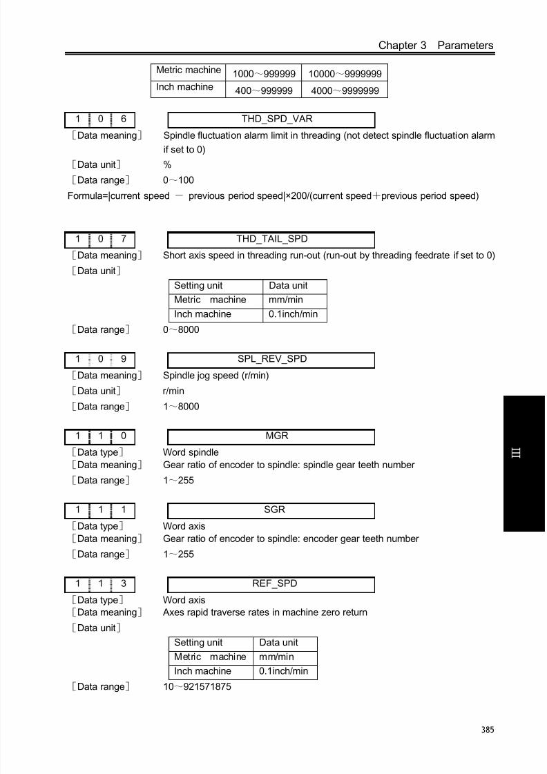
8/17/2019 980TDc CNC Turning Controller User Manual
http://slidepdf.com/reader/full/980tdc-cnc-turning-controller-user-manual 400/461
Chapter 3 Parameters
385
V ol um e
C onn e c t i on
Metric machine 1000~999999 10000~9999999
Inch machine 400~999999 4000~9999999
1 0 6 THD_SPD_VAR
[Data meaning] Spindle fluctuation alarm limit in threading (not detect spindle fluctuation alarmif set to 0)
[Data unit] %
[Data range] 0~100
Formula=|current speed - previous period speed|×200/(current speed+previous period speed)
1 0 7 THD_TAIL_SPD
[Data meaning] Short axis speed in threading run-out (run-out by threading feedrate if set to 0)
[Data unit] Setting unit Data unit
Metric machine mm/min
Inch machine 0.1inch/min
[Data range] 0~8000
1 0 9 SPL_REV_SPD
[Data meaning] Spindle jog speed (r/min)
[Data unit] r/min
[Data range] 1~8000
1 1 0 MGR
[Data type] Word spindle
[Data meaning] Gear ratio of encoder to spindle: spindle gear teeth number
[Data range] 1~255
1 1 1 SGR
[Data type] Word axis
[Data meaning] Gear ratio of encoder to spindle: encoder gear teeth number[Data range] 1~255
1 1 3 REF_SPD
[Data type] Word axis
[Data meaning] Axes rapid traverse rates in machine zero return
[Data unit]
Setting unit Data unit
Metric machine mm/min
Inch machine 0.1inch/min
[Data range] 10~921571875

8/17/2019 980TDc CNC Turning Controller User Manual
http://slidepdf.com/reader/full/980tdc-cnc-turning-controller-user-manual 401/461
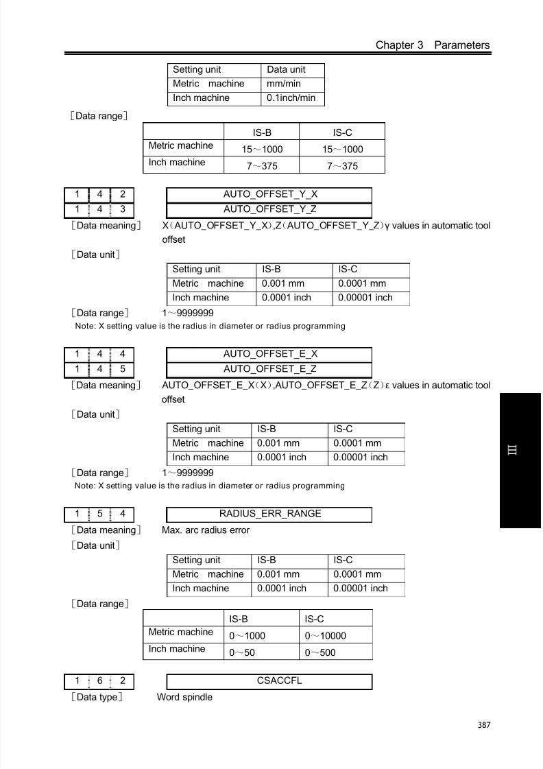
8/17/2019 980TDc CNC Turning Controller User Manual
http://slidepdf.com/reader/full/980tdc-cnc-turning-controller-user-manual 402/461
Chapter 3 Parameters
387
V ol um e
C onn e c t i on
Setting unit Data unit
Metric machine mm/min
Inch machine 0.1inch/min
[Data range]
IS-B IS-CMetric machine 15~1000 15~1000
Inch machine 7~375 7~375
1 4 2 AUTO_OFFSET_Y_X
1 4 3 AUTO_OFFSET_Y_Z
[Data meaning] X( AUTO_OFFSET_Y_X),Z( AUTO_OFFSET_Y_Z)γ values in automatic tool
offset
[Data unit]
Setting unit IS-B IS-CMetric machine 0.001 mm 0.0001 mm
Inch machine 0.0001 inch 0.00001 inch
[Data range] 1~9999999
Note: X setting value is the radius in diameter or radius programming
1 4 4 AUTO_OFFSET_E_X
1 4 5 AUTO_OFFSET_E_Z
[Data meaning] AUTO_OFFSET_E_X(X),AUTO_OFFSET_E_Z(Z)ε values in automatic tool
offset[Data unit]
Setting unit IS-B IS-C
Metric machine 0.001 mm 0.0001 mm
Inch machine 0.0001 inch 0.00001 inch
[Data range] 1~9999999
Note: X setting value is the radius in diameter or radius programming
1 5 4 RADIUS_ERR_RANGE
[Data meaning] Max. arc radius error
[Data unit]
Setting unit IS-B IS-C
Metric machine 0.001 mm 0.0001 mm
Inch machine 0.0001 inch 0.00001 inch
[Data range]
IS-B IS-C
Metric machine 0~1000 0~10000
Inch machine 0~50 0~500
1 6 2 CSACCFL
[Data type] Word spindle

8/17/2019 980TDc CNC Turning Controller User Manual
http://slidepdf.com/reader/full/980tdc-cnc-turning-controller-user-manual 403/461
GSK980TDc Turning CNC System User Manual
388
V ol um e
C onn e c t i on
[Data meaning] initial speed of CS acceleration/deceleration
[Data unit] deg/min
[Data range] 0~4000
1 6 3 CSACCTIME[Data type] Word spindle
[Data meaning] acceleration/deceleration time constant of CS
[Data unit] ms
[Data range] 0~4000
1 6 6 CAACCFL
[Data type] Word spindle
[Data meaning] initial speed of linear acceleration/deceleration in rigid tapping
[Data unit] Setting unit Data unit
Metric machine mm/min
Inch machine 0.1inch/min
[Data range] 0~4000
1 6 7 CAACCTIME
[Data meaning] linear acceleration/deceleration time constant in rigid tapping tool in-feed
[Data unit] ms
[Data range] 0~4000
1 6 9 RTAPBACKRATE
[Data meaning] override value in rigid tapping tool retraction (override is 100% when it is set to
0)
[Data unit] %
[Data range] 0~200
1 7 0 CMCODE
[Data meaning] M code used for spindle clamping during rigid tapping
[Data unit]
[Data range] 3~97
1 7 1 CAMAX_S
[Data meaning] max. spindle speed in rigid tapping
[Data unit] r/min
[Data range] 0~6000
2 1 6 ROT_REVY
[Data meaning] Y(ROT_REVY),4th(ROT_REV4),5th(ROT_REV5)is the movement pre
revolution of rotary axis
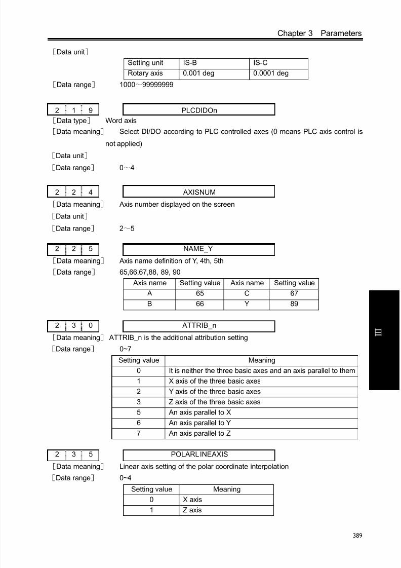
8/17/2019 980TDc CNC Turning Controller User Manual
http://slidepdf.com/reader/full/980tdc-cnc-turning-controller-user-manual 404/461
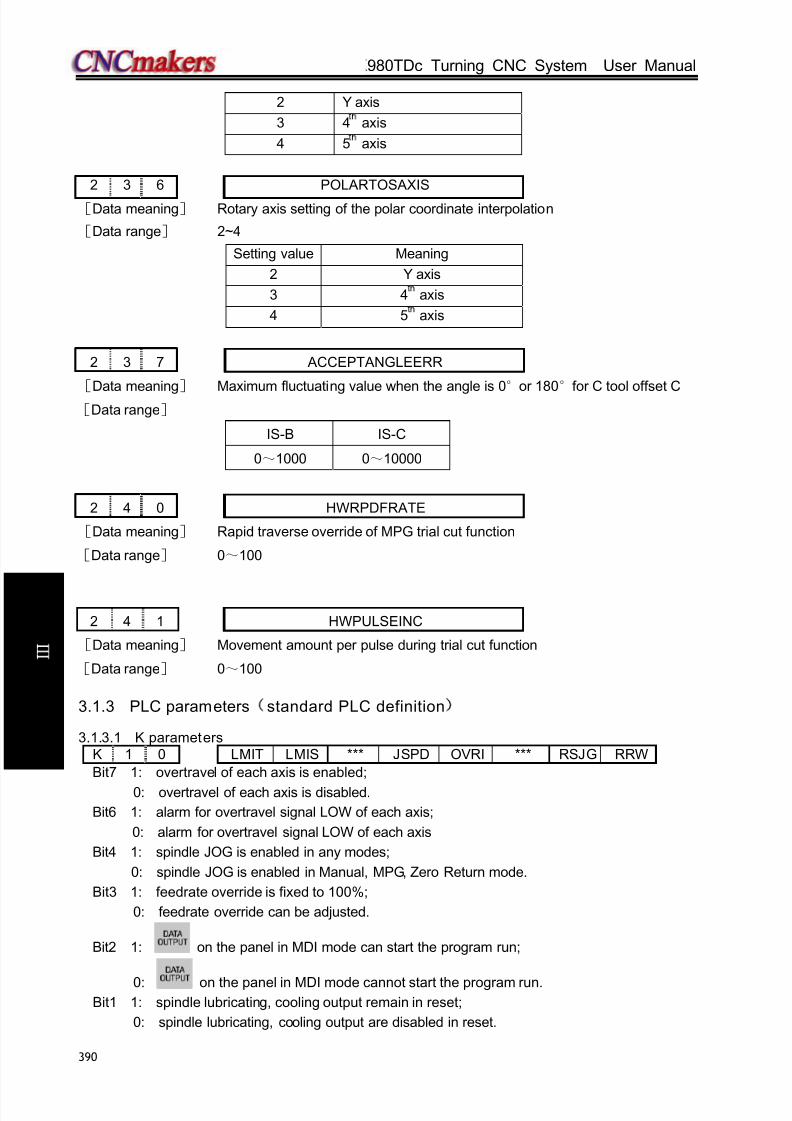
8/17/2019 980TDc CNC Turning Controller User Manual
http://slidepdf.com/reader/full/980tdc-cnc-turning-controller-user-manual 405/461
GSK980TDc Turning CNC System User Manual
390
V ol um e
C onn e c t i on
2 Y axis
3 4 axis
4 5 axis
2 3 6 POLARTOSAXIS
[Data meaning] Rotary axis setting of the polar coordinate interpolation
[Data range] 2~4
Setting value Meaning
2 Y axis
3 4 axis
4 5 axis
2 3 7 ACCEPTANGLEERR
[Data meaning
] Maximum fluctuating value when the angle is 0
°or 180
°for C tool offset C
[Data range]
IS-B IS-C
0~1000 0~10000
2 4 0 HWRPDFRATE
[Data meaning] Rapid traverse override of MPG trial cut function
[Data range] 0~100
2 4 1 HWPULSEINC
[Data meaning] Movement amount per pulse during trial cut function
[Data range] 0~100
3.1.3 PLC parameters standard PLC definition)
3.1.3.1 K parameters
K 1 0 LMIT LMIS *** JSPD OVRI *** RSJG RRW
Bit7 1: overtravel of each axis is enabled;
0: overtravel of each axis is disabled.
Bit6 1: alarm for overtravel signal LOW of each axis;
0: alarm for overtravel signal LOW of each axis
Bit4 1: spindle JOG is enabled in any modes;
0: spindle JOG is enabled in Manual, MPG, Zero Return mode.
Bit3 1: feedrate override is fixed to 100%;
0: feedrate override can be adjusted.
Bit2 1: on the panel in MDI mode can start the program run;
0: on the panel in MDI mode cannot start the program run.Bit1 1: spindle lubricating, cooling output remain in reset;
0: spindle lubricating, cooling output are disabled in reset.

8/17/2019 980TDc CNC Turning Controller User Manual
http://slidepdf.com/reader/full/980tdc-cnc-turning-controller-user-manual 406/461
Chapter 3 Parameters
391
V ol um e
C onn e c t i on
Bit0 1: the cursor returning to the beginning of the program is enabled in any working mode in
reset;
0: the cursor returning to the beginning of the program is enabled in Edit working mode.
K 1 1 CHOT CHET TCPS CTCP TSGN CHTB CHTA
Bit7 1: checks the tool post worktable overheating;
0: does not check the tool post worktable overheating.
Bit5 1: checks the tool signal when the tool change is completed;
0: does not check the tool signal when the tool change is completed.
Bit4 1: tool post locking signal HIGH(be connected with +24V) is enabled;
0: tool post locking signal LOW(not be connected with +24V) is enabled
Bit3 1: checks the tool post locking signal;
0: does not check the tool post locking signal.
Bit2 1: tool signal LOW(not be connected with +24V) is enabled;
0: tool signal HIGH(be connected with +24V)is enabled.
Bit1 Bit0 : tool change mode selects Bit1 tool change mode selects Bit 0
K 1 2 RCKC CCHU NYQP SLSP SLQP
Bit4 1: External chuck control is enabled during program running;0: External chuck control is disabled during program running
Bit3 1: the system checks the chuck in-position signal;
0: the system does not check the chuck in-position signal.
Bit2 1: in outer mode, NQPJ is the outer chuck released signal, and WQPJ is the outer chuck
clamped signal;
0: in inner mode, NQPJ is the inner chuck clamped signal, and WQPJ is the inner chuck
released signal.
Bit1 1: the system does not check whether the chuck is clamped when the chuck function is
enabled;
0: the system checks whether the chuck is clamped when the chuck function is enabled;when the chuck is not clamped, the system cannot start the spindle and alarms.
Bit0 1: the chuck control function is enabled;
0: the chuck control function is disabled.
K 1 3 RTSC SPTW SLTW
Bit2 1: External tailstock control is enabled during program running;
0: External tailstock control is disabled during program running;
Bit1 1: the spindle rotation and the tailstock forward/backward does not interlock, the tailstock
executes the forward no matter what the spindle is in any states; the spindle rotates nomatter what the tailstock is in any states;
0: the spindle rotation and the tailstock forward/backward interlock, the tailstock cannot
CHTB CHTA Tool post type
0 0 Standard tool change mode B
0 1 Standard tool change mode A
1 0 Yantai AK31 series(6, 8, 10, 12 tools)
1 1 Liuxin hydraulic tool post(8, 10, 12 tools)
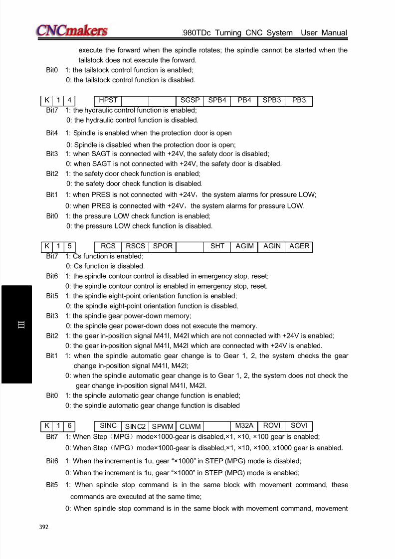
8/17/2019 980TDc CNC Turning Controller User Manual
http://slidepdf.com/reader/full/980tdc-cnc-turning-controller-user-manual 407/461
GSK980TDc Turning CNC System User Manual
392
V ol um e
C onn e c t i on
execute the forward when the spindle rotates; the spindle cannot be started when the
tailstock does not execute the forward.
Bit0 1: the tailstock control function is enabled;
0: the tailstock control function is disabled.
K 1 4 HPST SGSP SPB4 PB4 SPB3 PB3
Bit7 1: the hydraulic control function is enabled;
0: the hydraulic control function is disabled.
Bit4 1: Spindle is enabled when the protection door is open
0: Spindle is disabled when the protection door is open;
Bit3 1: when SAGT is connected with +24V, the safety door is disabled;
0: when SAGT is not connected with +24V, the safety door is disabled.
Bit2 1: the safety door check function is enabled;
0: the safety door check function is disabled.
Bit1 1: when PRES is not connected with +24V,the system alarms for pressure LOW;0: when PRES is connected with +24V,the system alarms for pressure LOW.
Bit0 1: the pressure LOW check function is enabled;
0: the pressure LOW check function is disabled.
K 1 5 RCS RSCS SPOR SHT AGIM AGIN AGER
Bit7 1: Cs function is enabled;
0: Cs function is disabled.
Bit6 1: the spindle contour control is disabled in emergency stop, reset;
0: the spindle contour control is enabled in emergency stop, reset.
Bit5 1: the spindle eight-point orientation function is enabled;
0: the spindle eight-point orientation function is disabled.
Bit3 1: the spindle gear power-down memory;
0: the spindle gear power-down does not execute the memory.
Bit2 1: the gear in-position signal M41I, M42I which are not connected with +24V is enabled;
0: the gear in-position signal M41I, M42I which are connected with +24V is enabled.
Bit1 1: when the spindle automatic gear change is to Gear 1, 2, the system checks the gear
change in-position signal M41I, M42I;
0: when the spindle automatic gear change is to Gear 1, 2, the system does not check the
gear change in-position signal M41I, M42I.
Bit0 1: the spindle automatic gear change function is enabled;
0: the spindle automatic gear change function is disabled
K 1 6 SINC SINC2 SPWM CLWM M32 A ROVI SOVI
Bit7 1: When Step(MPG)mode×1000-gear is disabled,×1, ×10, ×100 gear is enabled;
0: When Step(MPG)mode×1000-gear is disabled,×1, ×10, ×100, x1000 gear is enabled.
Bit6 1: When the increment is 1u, gear “×1000” in STEP (MPG) mode is disabled;
0: When the increment is 1u, gear “×1000” in STEP (MPG) mode is enabled;
Bit5 1: When spindle stop command is in the same block with movement command, these
commands are executed at the same time;
0: When spindle stop command is in the same block with movement command, movement
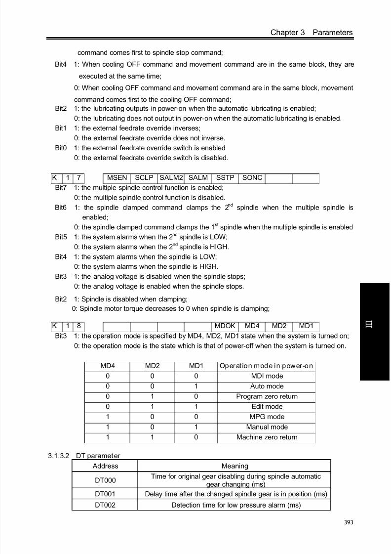
8/17/2019 980TDc CNC Turning Controller User Manual
http://slidepdf.com/reader/full/980tdc-cnc-turning-controller-user-manual 408/461
Chapter 3 Parameters
393
V ol um e
C onn e c t i on
command comes first to spindle stop command;
Bit4 1: When cooling OFF command and movement command are in the same block, they are
executed at the same time;
0: When cooling OFF command and movement command are in the same block, movement
command comes first to the cooling OFF command;Bit2 1: the lubricating outputs in power-on when the automatic lubricating is enabled;
0: the lubricating does not output in power-on when the automatic lubricating is enabled.
Bit1 1: the external feedrate override inverses;
0: the external feedrate override does not inverse.
Bit0 1: the external feedrate override switch is enabled
0: the external feedrate override switch is disabled.
K 1 7 MSEN SCLP SALM2 SALM SSTP SONC
Bit7 1: the multiple spindle control function is enabled;
0: the multiple spindle control function is disabled.
Bit6 1: the spindle clamped command clamps the 2nd spindle when the multiple spindle is
enabled;
0: the spindle clamped command clamps the 1st spindle when the multiple spindle is enabled
Bit5 1: the system alarms when the 2nd spindle is LOW;
0: the system alarms when the 2nd spindle is HIGH.
Bit4 1: the system alarms when the spindle is LOW;
0: the system alarms when the spindle is HIGH.
Bit3 1: the analog voltage is disabled when the spindle stops;
0: the analog voltage is enabled when the spindle stops.
Bit2 1: Spindle is disabled when clamping;
0: Spindle motor torque decreases to 0 when spindle is clamping;
K 1 8 MDOK MD4 MD2 MD1
Bit3 1: the operation mode is specified by MD4, MD2, MD1 state when the system is turned on;
0: the operation mode is the state which is that of power-off when the system is turned on.
MD4 MD2 MD1 Operat ion mode in power-on
0 0 0 MDI mode
0 0 1 Auto mode0 1 0 Program zero return
0 1 1 Edit mode
1 0 0 MPG mode
1 0 1 Manual mode
1 1 0 Machine zero return
3.1.3.2 DT parameter
Address Meaning
DT000Time for original gear disabling during spindle automatic
gear changing (ms)DT001 Delay time after the changed spindle gear is in position (ms)
DT002 Detection time for low pressure alarm (ms)

8/17/2019 980TDc CNC Turning Controller User Manual
http://slidepdf.com/reader/full/980tdc-cnc-turning-controller-user-manual 409/461
GSK980TDc Turning CNC System User Manual
394
V ol um e
C onn e c t i on
Address Meaning
DT004 Permit time for tool changing (ms)
DT005 M command execution time (ms)
DT006 S command execution time (ms)
DT007 Delay time for tool post from CW to CCW output (ms)
DT008 Tool post lock signal detection time (ms)
DT009 Tool post CCW rotation lock time (ms)
DT010 Spindle braking delay output time (ms)
DT011 Spindle braking output time (ms)
DT012 Spindle JOG time (ms)
DT013 Time for manual lubricating ON (0: time is not limited) (ms)
DT014 Chuck clamping command execution time (ms)
DT015 Chuck unclamping command execution time (ms)
DT016 Interval of automatic lubricating (ms) (can be modifieddirectly)
DT017Time for automatic lubrication output (ms) (can be modified
directly)
DT018 Chuck pulse output width (ms) (can be modified directly)
DT020 Spindle clamping/unclamping time (ms)
DT021 Spindle stop, chuck enable delay time (ms)
DT023Delay time before spindle motor torque decreases to 0 after
spindle starts clamping
3.1.3.3 DC parameters Address Meaning
DC000 Spindle zero speed output range (r/min)
3.2 Parameter Description (by function sequence)
3.2.1 X, Z, Y, 4th,5th axis control logic
0 0 1 *** *** *** ISC
Bit1 1: IS-C incremental system;
0: IS-B incremental system.
ISC Least input increment, least command increment Abbreviation
0 0.001mm,0.0001inch IS-B
1 0.0001mm,0.00001inch IS-C
0 0 5 PCMD
PCMD =1: CNC output wave is pulse
=0: CNC output wave is square
0 0 8 DIR5 DIR4 DIRY DIRZ DIRX

8/17/2019 980TDc CNC Turning Controller User Manual
http://slidepdf.com/reader/full/980tdc-cnc-turning-controller-user-manual 410/461
Chapter 3 Parameters
395
V ol um e
C onn e c t i on
Bit4 1: Direction signal (DIR) is HIGH when 5th positively moves ;
0: Direction signal (DIR) is HIGH when 5th negatively moves.
Bit3 1: Direction signal (DIR) is HIGH when 4th positively moves;
0: Direction signal (DIR) is HIGH when 4th negatively moves.
Bit2 1: Direction signal (DIR) is HIGH when Y positively moves ;
0: Direction signal (DIR) is HIGH when Y negatively moves.
Bit1 1: Direction signal (DIR) is HIGH when Z positively moves;
0: Direction signal (DIR) is HIGH when Z negatively moves.
Bit0 1: Direction signal (DIR) is HIGH when X positively moves;
0: Direction signal (DIR) is HIGH when X negatively moves.
If machine moving direction is inconsistent with the actually required direction, it may be
adjusted by this parameter.
0 0 9 5ALM 4ALM YALM ZALM XALM
Bit4 1: 5th alarm signal (ALM5) is LOW alarm;
0: 5th alarm signal (ALM5) is HIGH alarm.
Bit3 1: 4th alarm signal (ALM4) is LOW alarm;
0: 4th alarm signal (ALM4) is HIGH alarm.
Bit2 1: Y alarm signal (ALMY) is LOW alarm;
0: Y alarm signal (ALMY) is HIGH alarm.
Bit1 1: Z alarm signal (ZALM) is LOW alarm;
0: Z alarm signal (ZALM) is HIGH alarm.
Bit0 1: X alarm signal (XALM) is LOW alarm;
0: X alarm signal (XALM) is HIGH alarm.
This parameter may be adjusted based on the drive unit alarm s ignal level output.
1 7 5 SPFD
SPFD =1: Feeding stops if spindle stops in cutting
=0: Feeding not stop if spindle stops in cutting
1 8 7 YIS1Y Y IS0 *** *** ***
[Data type]: Bit axisBIT7,BIT6: set Y incremental system, 00: consistent with the incremental system of the system, 01:
IS-A,10: IS-B;11: IS-C.2 0 3 *** *** *** ABP5 ABP4 ABPY ABPZ ABPX
Bit4 1: 5th pulse outputs according to the two-phase quadradure (need to power-on again);
0: 5th pulse outputs according to (pulse + direction) (need to power-on again).
Bit3 1: 4th pulse outputs according to the two-phase quadradure (need to power-on again);
0: 4th pulse outputs according to (pulse + direction) (need to power-on again).
Bit2 1: Y pulse outputs according to the two-phase quadradure (need to power-on again);
0: Y pulse outputs according to (pulse + direction) (need to power-on again).
Bit1 1: Z pulse outputs according to the two-phase quadradure (need to power-on again);
0: Z pulse outputs according to (pulse + direction) (need to power-on again).
Bit0 1: X pulse outputs according to the two-phase quadradure (need to power-on again);0: X pulse outputs according to (pulse + direction) (need to power-on again).

8/17/2019 980TDc CNC Turning Controller User Manual
http://slidepdf.com/reader/full/980tdc-cnc-turning-controller-user-manual 411/461
GSK980TDc Turning CNC System User Manual
396
V ol um e
C onn e c t i on
3.2.2 Acceleration & deceleration control
0 2 2 RPDFn
[Data type] Word axis
[Data meaning] max. speed of X rapid traverse (radius value)
[Data unit] Setting unit Data unit
Metric machine mm/min
Inch machine 0.1inch/min
[Data range] 10~99999999
0 2 3 LINTn
[Data type] Word axis
[Data meaning] Acceleration/deceleration time constant value
[Data unit] ms[Data range] 10~4000
0 2 7 FEDM
[Data meaning] Upper limit of cutting feedrate
[Data unit]
Setting unit Data unit
Metric machine mm/min
Inch machine 0.1inch/min
[Data range]
IS-B IS-C
Metric machine 10~15000 10~15000
Inch machine 5~5800 10~5800
0 2 9 FEEDT
[Data meaning] Acceleration/deceleration time constant during cutting feed and manual feed
[Data unit] ms
[Data range] 0~4000
0 3 0 FEDFL
[Data meaning] The starting speed of cutting feed
[Data unit]
Setting unit Data unit
Metric machine mm/min
Inch machine 0.1inch/min
[Data range] IS-B IS-C

8/17/2019 980TDc CNC Turning Controller User Manual
http://slidepdf.com/reader/full/980tdc-cnc-turning-controller-user-manual 412/461
Chapter 3 Parameters
397
V ol um e
C onn e c t i on
Metric machine 0~8000 0~8000
Inch machine 0~3000 0~3000
0 3 1 JOGSPEED
[Data meaning] Set speed when manual feedrate override is 100%
[Data unit]
Setting unit Data unit
Metric machine mm/min
Inch machine 0.1inch/min
[Data range] 10~30000
0 3 2 RPDFLn
[Data type] Word axis[Data meaning] The rapid traverse rate when the override is F0
[Data unit]
Setting unit Data unit
Metric machine mm/min
Inch machine 0.1inch/min
[Data range]
IS-B IS-C
Metric machine 0~4000 0~4000
Inch machine 0~1500 0~1500
3.2.3 Precision compensation
0 0 3 PEC
Bit5 1: Pitch error offset active
0: Pitch error offset inactive
0 1 0 *** *** *** CPF5 CPF4 CPF3 CPF2 CPF1
CPF4~CPF1: Setting values of backlash offset pulse frequency (by BCD code)
The set frequency =(setting value+1) Kpps
CPF5 CPF4 CPF3 CPF2 CPF1 Set frequency(Kpps)
0 0 0 0 0 1
0 0 0 0 1 2
0 0 0 1 0 3
0 0 0 1 1 4
0 0 1 0 0 5
0 0 1 0 1 6
0 0 1 1 0 7
0 0 1 1 1 8
0 1 0 0 0 9
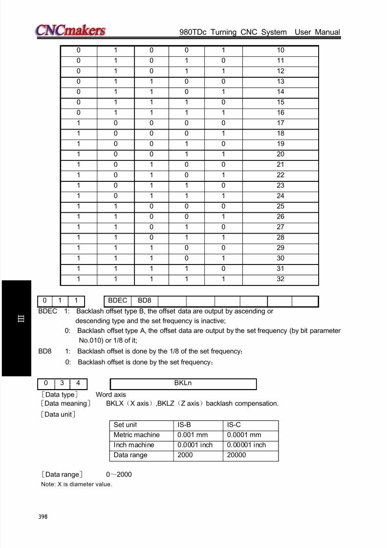
8/17/2019 980TDc CNC Turning Controller User Manual
http://slidepdf.com/reader/full/980tdc-cnc-turning-controller-user-manual 413/461
GSK980TDc Turning CNC System User Manual
398
V ol um e
C onn e c t i on
0 1 0 0 1 10
0 1 0 1 0 11
0 1 0 1 1 12
0 1 1 0 0 13
0 1 1 0 1 14
0 1 1 1 0 15
0 1 1 1 1 16
1 0 0 0 0 17
1 0 0 0 1 18
1 0 0 1 0 19
1 0 0 1 1 20
1 0 1 0 0 21
1 0 1 0 1 22
1 0 1 1 0 23
1 0 1 1 1 24
1 1 0 0 0 25
1 1 0 0 1 26
1 1 0 1 0 27
1 1 0 1 1 28
1 1 1 0 0 29
1 1 1 0 1 30
1 1 1 1 0 31
1 1 1 1 1 32
0 1 1 BDEC BD8
BDEC 1: Backlash offset type B, the offset data are output by ascending or
descending type and the set frequency is inactive;
0: Backlash offset type A, the offset data are output by the set frequency (by bit parameter
No.010) or 1/8 of it;
BD8 1: Backlash offset is done by the 1/8 of the set frequency;
0: Backlash offset is done by the set frequency;
0 3 4 BKLn[Data type] Word axis
[Data meaning] BKLX(X axis),BKLZ(Z axis)backlash compensation.
[Data unit]
Set unit IS-B IS-C
Metric machine 0.001 mm 0.0001 mm
Inch machine 0.0001 inch 0.00001 inch
Data range 2000 20000
[Data range] 0~2000
Note: X is diameter value.

8/17/2019 980TDc CNC Turning Controller User Manual
http://slidepdf.com/reader/full/980tdc-cnc-turning-controller-user-manual 414/461
Chapter 3 Parameters
399
V ol um e
C onn e c t i on
0 9 6 PECMINn
[Data type] Word axis
[Data meaning] Minimum pitch error compensation number
[Data range] 0~1023
0 9 7 PECMAXn
[Data type] Word axis
[Data meaning] Maximum pitch error compensation number
[Data range] 0~1023
0 9 8 PECORGn
[Data type] Word axis
[Data meaning] Pitch error compensation number corresponding to machine zero
[Data range] 0~1023
0 9 9 PECINTn
[Data type] Word axis
[Data meaning] Pitch error compensation intervals
[Data unit]
Setting unit IS-B IS-C
Metric machine 0.001 mm 0.0001 mm
Inch machine 0.0001 inch 0.00001 inch[Data range]
IS-B IS-C
Metric machine 1000~999999 10000~9999999
Inch machine 400~999999 4000~9999999
3.2.4 Machine protection
1 7 2 *** MST MSP MOT ESP *** LZR ***
Bit6 1: External cycle start signal (ST) inactive, it is not the cycle start switch and can be defined by
macro code (#1014);
0: External cycle start signal (ST) active.
Bit5 1: External SP signal inactive, and it is not the dwell switch and can be defined by macro code.
( #1015);
0: External SP signal active with external dwell switch connected, otherwise CNC shows
“stop”.mailto:M@SP=1
Bit4 1: Do not detect software stroke limit;
0: Detect software stroke limit.
Bit3 1: Emergency stop inactive;
0: Emergency stop active; Bit1 1: The software limit is valid after system is energized and before machine zero return is
performed;

8/17/2019 980TDc CNC Turning Controller User Manual
http://slidepdf.com/reader/full/980tdc-cnc-turning-controller-user-manual 415/461
GSK980TDc Turning CNC System User Manual
400
V ol um e
C onn e c t i on
0: The software limit is invalid after system is energized and before machine zero return isperformed;
0 4 5 LT1n1
0 4 6 LT1n2[Data type] Word axis
[Data meaning] LT1n1: Maximum stroke on positive direction; LT1n2: Maximum stroke on
negative direction
[Data Unit]
Setting unit IS-B IS-C
Metric machine 0.001 mm 0.0001 mm
Inch 0.0001 inch 0.00001 inch
[Data range] -99999999~99999999
Note: When bit 2 of parameter No. 001 set diameter programming, X axis is set by diameter system; when bit 2 set
radius programming, X axis is set by radius system.
PLC parameter
D T 0 2 PEALMTIM
[Data meaning] Under-pressure alarm detection time
[Data unit] ms
[Data range] 0~2147483647
D T 2 1 PSANGNT
[Data meaning] Chuck operation delay time after spindle stop;
[Data unit] ms
[Data range] 0~2147483647
3.2.5 Machine zero return
0 0 4 *** DECI ***
Bit5 1: Deceleration begins as DEC signal is connected to +24V in machine zero return
0: Deceleration begins as DEC signal is disconnected to +24V in machine zero return
0 0 5 PPD
Bit1 1: Relative and absolute coordinate set together for absolute setting and reference return by
G50
0: Only absolute coordinate set for absolute setting and reference point by G50
0 0 6 ZM5 ZM4 ZMY ZMZ ZMX
ZMX, ZMZ, ZMY, ZM4, ZM5: Return and initial backlash direction of X, Y, Z axes machine zeroes
at power on0: Zero return type C, machine zero return and backlash direction is positive;
1: Zero return type B, machine zero return and backlash direction is negative.

8/17/2019 980TDc CNC Turning Controller User Manual
http://slidepdf.com/reader/full/980tdc-cnc-turning-controller-user-manual 416/461
Chapter 3 Parameters
401
V ol um e
C onn e c t i on
0 0 7 ZC5 ZC4 ZCY ZCZ ZCX
ZCX, ZCZ, ZCY, ZC4, ZC5 =0: Separate DEC and zero signals needed during machine zero
return
=1: DEC and zero signals together by a proximity switch during
machine zero returnNote: This parameter should be set to 1 if a proximity switch is taken as both deceleration and zero signal.
0 1 1 *** *** NORF ZNIK *** ***
Bit3 1: Manual machine zero return inactivity
0: Manual machine zero return active
Bit2 1: Stop at zero by pressing direction key once in zero return with direction key locked;
0: Direction key should be held on in zero return with direction key unlocked.
0 1 2 APRS *** *** ISOTBit7 1: ABSOLUTE automatically set after reference return, the coordinate set by parameter
No.049 and No.050;
0: ABSOLUTE not automatically set after reference return
Bit 6 1: Prior to machine zero return after power-on or E-stop, manual rapid traverse active
0: Prior to machine zero return after power-on or E-stop, manual rapid traverse inactive
0 1 4 ZRS5 ZRS4 ZRSY ZRSZ ZRSX
Bit4, Bit3, Bit2, Bit1, Bit0 1: 5th, 4th, Y, Z, X has machine zero, the system detects DEC signal and
zero signal in executing machine zero return.
0: 5th, 4th, Y, Z, X has machine zero, the system does not detect DECsignal and zero signal in executing machine zero return
1 8 3 *** *** *** MZRY MZRY MZRY MZRZ MARX
Bit4 1: 5th press key_ to execute machine zero return;
0: 5th press key_ to execute machine zero return(has not defined the press key in the standard
PLC)
Bit3 1: 4th to execute the machine zero return;
0: 4th
to execute the machine zero return.Bit2 1: Y to execute the machine zero return;
0: Y to execute the machine zero return.
Bit1 1: Z to execute the machine zero return;
0: Z to execute the machine zero return.
Bit0 1: X to execute the machine zero return;
0: X to execute the machine zero return.
1 8 8 *** RRTn *** *** ***
[Data type] Bit axis
RRTn 1: when Y,4th , 5th are rotary axis, the zero return use D mode;

8/17/2019 980TDc CNC Turning Controller User Manual
http://slidepdf.com/reader/full/980tdc-cnc-turning-controller-user-manual 417/461
GSK980TDc Turning CNC System User Manual
402
V ol um e
C onn e c t i on
0: when Y,4th ,5th are rotary axis, the zero return use A, B,C mode( need to power-on again).
0 3 3 ZRNFL
[Data type] Word axis
[Data meaning] Lowest speed rate of X,Z machine zero return.[Data unit]
Set unit Data unit
Metric machine mm/min
Inch machine 0.1inch/min
[Data range] 6~4000
0 4 7 PRSn
[Data type] Word axis
[Data meaning] Setting value of absolute coordinate after machine zero return is performed
[Data unit]
Setting unit IS-B IS-C
Metric input 0.001 mm 0.0001 mm
Inch input 0.0001 inch 0.00001 inch
[Data range] -99999999~99999999
1 1 3 REF_SPD
[Data meaning
] high-speed of X,Z machine zero return.
[Data unit]
Set unit Data unit
Metric machine mm/min
Inch machine 0.1inch/min
[Data range] 10~921571875
1 1 4 REF_OFFSETX
[Data type] Word axis
[Data meaning] Offset value of machine zero point[Data unit]
Set unit IS-B IS-C
Metric input 0.001 mm 0.0001 mm
Inch input 0.0001 inch 0.00001 inch
[Data range] -99999~99999
1 2 0 REF1_COORDn
1 2 1 REF2_COORDn
1 2 2 REF3_COORDn1 2 3 REF4_COORDn
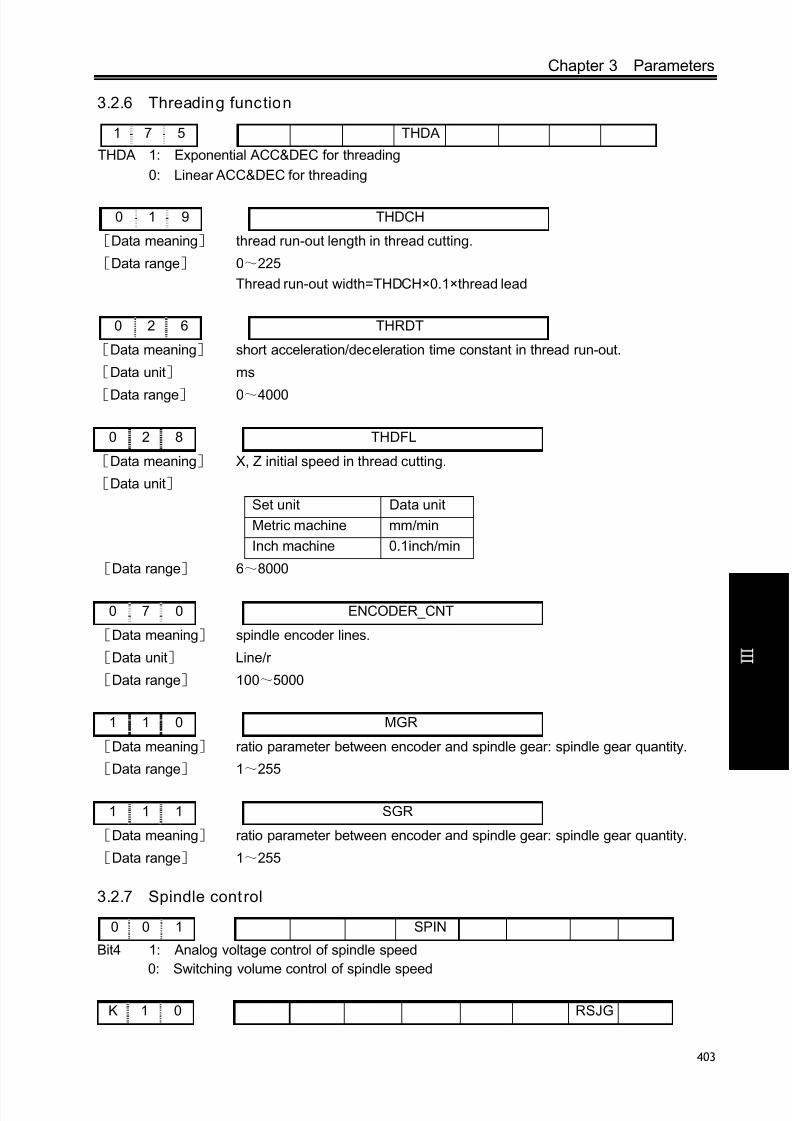
8/17/2019 980TDc CNC Turning Controller User Manual
http://slidepdf.com/reader/full/980tdc-cnc-turning-controller-user-manual 418/461
Chapter 3 Parameters
403
V ol um e
C onn e c t i on
3.2.6 Threading function
1 7 5 THDA
THDA 1: Exponential ACC&DEC for threading
0: Linear ACC&DEC for threading
0 1 9 THDCH
[Data meaning] thread run-out length in thread cutting.
[Data range] 0~225
Thread run-out width=THDCH×0.1×thread lead
0 2 6 THRDT
[Data meaning] short acceleration/deceleration time constant in thread run-out.
[Data unit] ms
[Data range] 0~4000
0 2 8 THDFL
[Data meaning] X, Z initial speed in thread cutting.
[Data unit]
Set unit Data unit
Metric machine mm/min
Inch machine 0.1inch/min
[Data range] 6~8000
0 7 0 ENCODER_CNT
[Data meaning] spindle encoder lines.
[Data unit] Line/r
[Data range] 100~5000
1 1 0 MGR
[Data meaning] ratio parameter between encoder and spindle gear: spindle gear quantity.
[Data range] 1~255
1 1 1 SGR
[Data meaning] ratio parameter between encoder and spindle gear: spindle gear quantity.
[Data range] 1~255
3.2.7 Spindle control
0 0 1 SPIN
Bit4 1: Analog voltage control of spindle speed
0: Switching volume control of spindle speed
K 1 0 RSJG

8/17/2019 980TDc CNC Turning Controller User Manual
http://slidepdf.com/reader/full/980tdc-cnc-turning-controller-user-manual 419/461
GSK980TDc Turning CNC System User Manual
404
V ol um e
C onn e c t i on
RSJG 1: when the reset is pressed, CNC does not close M03,M04,M08,M32 output signal;
0: when the reset is pressed, CNC closes M03, M04, M08, M32 output signal
0 2 1 PSANGNT
[Data meaning
] voltage offset compensation value when the analog voltage outputs 10V.
[Data unit] mV
[Data range] -2000~2000
0 3 6 SPDLC
[Data meaning] voltage offset compensation value when the analog voltage outputs 10V.
[Data unit] mV
[Data range] -1000~1000
0 3 7 GRMAX10 3 8 GRMAX2
0 3 9 GRMAX3
0 4 0 GRMAX4
[Data meaning] GRMAX1, GRMAX2, GRMAX3, GRMAX4: Max. speeds of spindle gear 1, 2,
3, 4 respectively when analog voltage output is 10V (function defined by
GSK980TDc PLC: if the spindle automatic gearing is active, they are the
speeds of M41, M42, M43, M44; if the automatic gearing is inactive or CNC is
powered on, the gears are memorized by parameter setting or the gear 1 is
defaulted.)
[Data unit] r/min
[Data range] 10~9999
0 6 7 SFTREV
[Data meaning] output voltage in spindle gear shifting.
[Data unit] mV
[Data range] 0~10000
0 6 8 SJOGREV
[Data meaning] spindle rotary axis speed in Manual (MPG) mode.[Data unit] r/min
[Data range] 0~3000
0 6 9 PEALMTIM
[Data meaning] pressure low alarm time width.
[Data unit] ms
[Data range] 0~60000
0 7 0 ENCODER_CNT[Data meaning] spindle encoder lines.
[Data unit] line/r
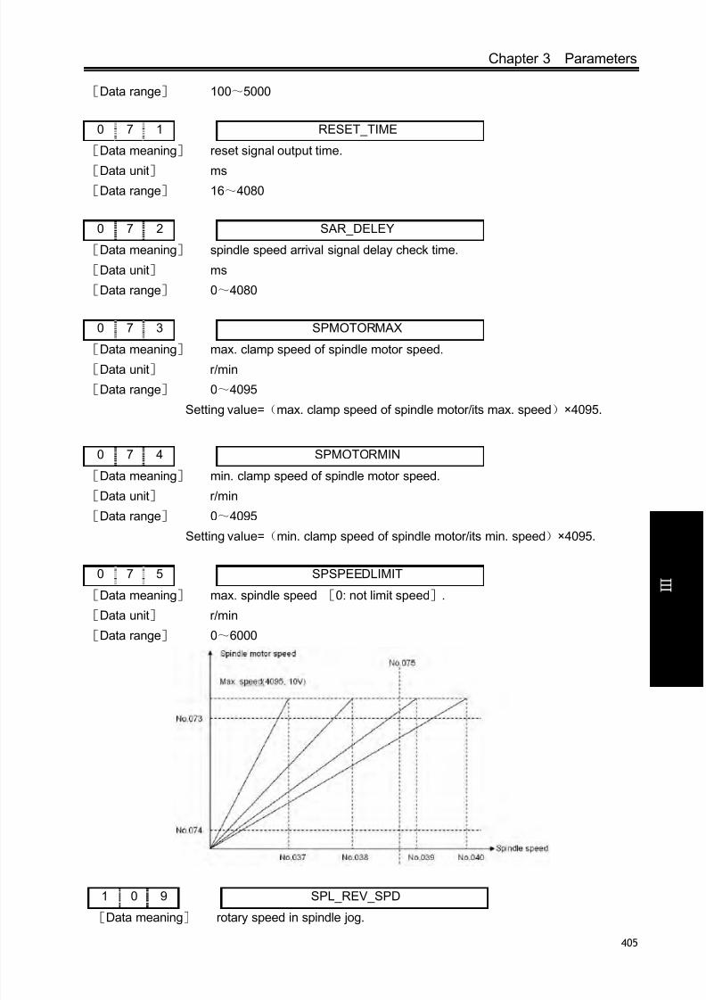
8/17/2019 980TDc CNC Turning Controller User Manual
http://slidepdf.com/reader/full/980tdc-cnc-turning-controller-user-manual 420/461
Chapter 3 Parameters
405
V ol um e
C onn e c t i on
[Data range] 100~5000
0 7 1 RESET_TIME
[Data meaning] reset signal output time.
[Data unit] ms[Data range] 16~4080
0 7 2 SAR_DELEY
[Data meaning] spindle speed arrival signal delay check time.
[Data unit] ms
[Data range] 0~4080
0 7 3 SPMOTORMAX
[Data meaning] max. clamp speed of spindle motor speed.[Data unit] r/min
[Data range] 0~4095
Setting value=(max. clamp speed of spindle motor/its max. speed)×4095.
0 7 4 SPMOTORMIN
[Data meaning] min. clamp speed of spindle motor speed.
[Data unit] r/min
[Data range] 0~4095
Setting value=(min. clamp speed of spindle motor/its min. speed)×4095.
0 7 5 SPSPEEDLIMIT
[Data meaning] max. spindle speed [0: not limit speed].
[Data unit] r/min
[Data range] 0~6000
1 0 9 SPL_REV_SPD
[Data meaning] rotary speed in spindle jog.
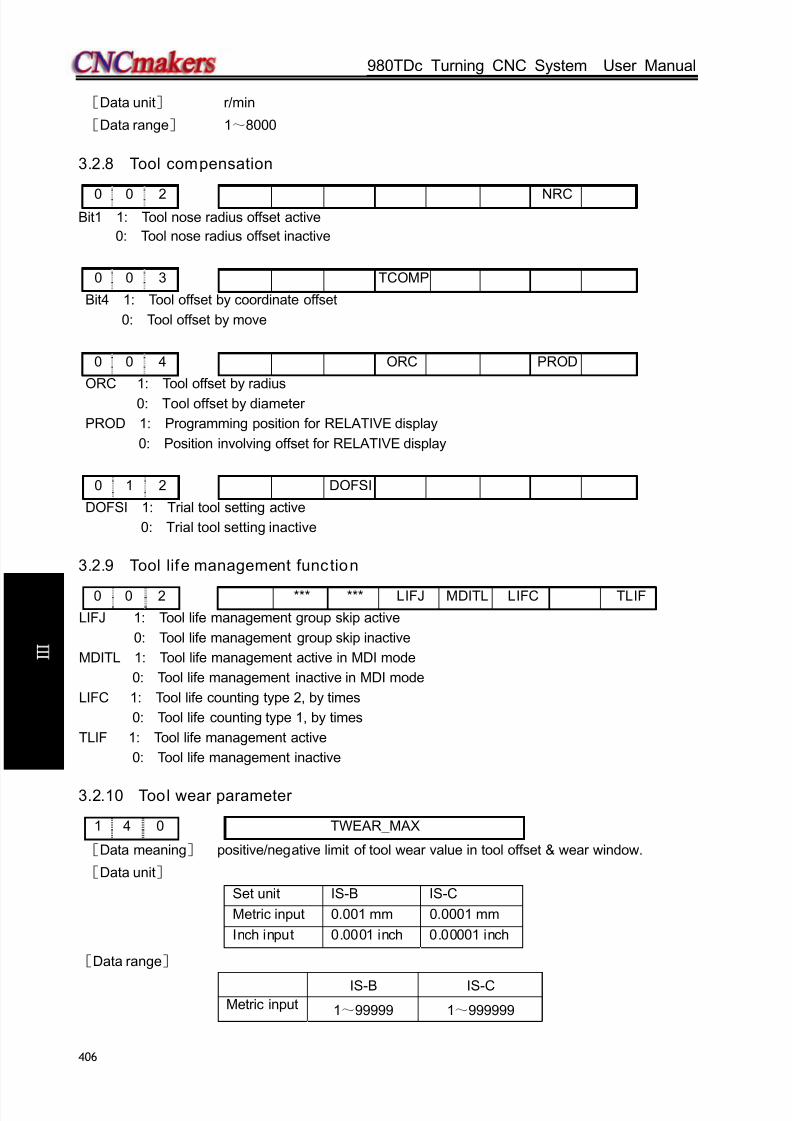
8/17/2019 980TDc CNC Turning Controller User Manual
http://slidepdf.com/reader/full/980tdc-cnc-turning-controller-user-manual 421/461
GSK980TDc Turning CNC System User Manual
406
V ol um e
C onn e c t i on
[Data unit] r/min
[Data range] 1~8000
3.2.8 Tool compensation
0 0 2 NRCBit1 1: Tool nose radius offset active
0: Tool nose radius offset inactive
0 0 3 TCOMP
Bit4 1: Tool offset by coordinate offset
0: Tool offset by move
0 0 4 ORC PROD
ORC 1: Tool offset by radius
0: Tool offset by diameter
PROD 1: Programming position for RELATIVE display
0: Position involving offset for RELATIVE display
0 1 2 DOFSI
DOFSI 1: Trial tool setting active
0: Trial tool setting inactive
3.2.9 Tool life management function
0 0 2 *** *** LIFJ MDITL LIFC TLIF
LIFJ 1: Tool life management group skip active
0: Tool life management group skip inactive
MDITL 1: Tool life management active in MDI mode
0: Tool life management inactive in MDI mode
LIFC 1: Tool life counting type 2, by times
0: Tool life counting type 1, by times
TLIF 1: Tool life management active
0: Tool life management inactive
3.2.10 Tool wear parameter
1 4 0 TWEAR_MAX
[Data meaning] positive/negative limit of tool wear value in tool offset & wear window.
[Data unit]
Set unit IS-B IS-C
Metric input 0.001 mm 0.0001 mm
Inch input 0.0001 inch 0.00001 inch
[Data range]
IS-B IS-CMetric input 1~99999 1~999999

8/17/2019 980TDc CNC Turning Controller User Manual
http://slidepdf.com/reader/full/980tdc-cnc-turning-controller-user-manual 422/461
Chapter 3 Parameters
407
V ol um e
C onn e c t i on
Inch input 1~99999 1~999999
3.2.11 Edit and display
0 0 5 M30
M30 1: Cursor to beginning after M300: Cursor to beginning by pressing CYCLE START key after M30
0 1 2 EAL EBCL
EAL 1: Program editing allowed during CNC alarming
0: Program editing unallowed during CNC alarming
EBCL 1: Program end sign EOB displayed for “;”
0: Program end sign EOB displayed for “*”
1 8 0 SPOS
Bit0 =1: DIS TO GO displayed in POS&PRG page
=0: RELATIVE POS displayed in POS&PRG page
1 8 4 *** PTEST *** *** *** L2 L1 L0
Bit0, Bit1, Bit2: Interface language selection
Language Bit2 Bit1 Bit0
Chinese 0 0 0
English 0 0 1
Portugal 0 1 0
Spanish 0 1 1
Russian 1 1 0
3.2.12 Communication setting
0 4 4 BRATE0
[Data meaning] baud rate of serial communication.
[Data unit] bit/s
[Data range] 1200,2400,4800,9600,19200,38400,57600 ,115200
3.2.13 MPG Parameters
0 0 1 *** *** MPG
Bit3 1: MPG mode
0: Step mode
0 1 3 *** *** *** HW5 HW4 HWY HWZ HWX
Bit4 1: coordinates increase when 5th MPG rotates CCW;
0: coordinates increase when 5th
MPG rotates CW.Bit3 1: coordinates increase when 4th MPG rotates CCW;
0: coordinates increase when 4th MPG rotates CW.

8/17/2019 980TDc CNC Turning Controller User Manual
http://slidepdf.com/reader/full/980tdc-cnc-turning-controller-user-manual 423/461
GSK980TDc Turning CNC System User Manual
408
V ol um e
C onn e c t i on
Bit2 1: coordinates increase when Y MPG rotates CCW;
0: coordinates increase when Y MPG rotates CW.
Bit1 1: coordinates increase when Z MPG rotates CCW;
0: coordinates increase when Z MPG rotates CW.
Bit0 1: coordinates increase when X MPG rotates CCW;
0: coordinates increase when X MPG rotates CW.
K 1 6 SINC SINC2 *** *** *** *** *** ***
Bit7 1: In STEP(MPG) mode and when the system increment is 0.1u, ×1000 gear is invalid,
0: In STEP(MPG) mode and when the system increment is 0.1u, ×1000 gear is valid,
Bit6 1: In STEP(MPG) mode and when the system increment is 1u, ×1000 gear is invalid,
0: In STEP(MPG) mode and when the system increment is 1u, ×1000 gear is valid,
Note: to avoid the step-out, the parameter should be set to 1 when the system is matched with the stepper
drive unit.
3.2.14 PLC axis control function
1 8 5 *** *** *** PRPD PLA
PRPD 1: Rapid traverse rate of PLC axis by input value
0: Rapid traverse rate of PLC axis by parameter value (X axis: No.022; Z axis:No.023;Y
axis:No.155;)
PLA 1: PLC axis control active, and active after repowering
0: PLC axis control inactive, and active after repowering
Note: The PLC axis control function is only provided by machine builder.
2 1 9 PLCDIDOn
[Data type] Word axis
[Data meaning] Select DI/DO in PLC axis control PLC
[Data unit]
[Data range] 0~4
3.2.15 Skip function
1 8 5 SK0 SKF *** *** ***
SK0 1: Skip input active as G31 signal is 0
0: Skip input active as G31 signal is 1
SKF 1: Feedrate override per minute or dry run active for G31
0: Feedrate override per minute or dry run inactive for G31Note: The skip function is only provided by machine builder.
3.2.16 Automatic tool setting function
1 8 5 AEO *** *** ***
AWO 1: when G36, G37 signal(XAE,ZAE)is 0, the input is valid;
0: G36, G37 signal(XAE,ZAE)is 1, the input is valid.

8/17/2019 980TDc CNC Turning Controller User Manual
http://slidepdf.com/reader/full/980tdc-cnc-turning-controller-user-manual 424/461
Chapter 3 Parameters
409
V ol um e
C onn e c t i on
1 4 1 AUTO_OFFSET_FEED
[Data meaning] feedrate in automatic tool compensation measure.
[Data unit]
Set unit Data unit
Metric machine mm/minInch machine 0.1inch/min
[Data range]
IS-B IS-C
Metric machine 15~1000 15~1000
Inch machine 7~375 7~375
1 4 2 AUTO_OFFSET_Y_X
1 4 3 AUTO_OFFSET_Y_Z
[Data meaning] X( AUTO_OFFSET_Y_X),Z( AUTO_OFFSET_Y_Z)γ value in automatic tool
offset.
[Data unit]
Set unit IS-B IS-C
Metric machine 0.001 mm 0.0001 mm
Inch machine 0.0001 inch 0.00001 inch
[Data range] 1~9999999
Note: X setting value is the radius in diameter programming and radius programming.
1 4 4 AUTO_OFFSET_E_X
1 4 5 AUTO_OFFSET_E_Z
[Data meaning] AUTO_OFFSET_E_X(X),AUTO_OFFSET_E_Z(Z)ε value in automatic tool
offset.
Note: The function needs the automatic tool setting device.
3.2.17 Input and output function in metric and inch system
0 0 1 *** *** INI
INI 1: Inch input0: Metric input
0 0 3 *** *** *** *** *** OIM
OIM 1: Offset automatically change in metric and inch conversion
0: Offset not change in metric and inch conversion
0 0 4 *** SCW
SCW 1: Inch system for min. code unit, active after repowering
0: Metric system for min. code unit, active after repowering

8/17/2019 980TDc CNC Turning Controller User Manual
http://slidepdf.com/reader/full/980tdc-cnc-turning-controller-user-manual 425/461
GSK980TDc Turning CNC System User Manual
410
V ol um e
C onn e c t i on
3.2.18 Parameters related to arc turning
1 5 4 RADIUS_ERR_RANGE
[Data meaning] max. value of arc radius error.
[Data unit]
Setting unit IS-B IS-C
Metric machine 0.001 mm 0.0001 mm
Inch machine 0.0001 inch 0.00001 inch
[Data range]
IS-B IS-C
Metric machine 0~1000 0~10000
Inch machine 0~50 0~500
3.2.19 Parameters related to the additional
1 8 7 YIS1Y Y IS0 RCSY *** *** *** ROSY ROTY
[Data type]: Bit axis
BIT7,BIT6: set Y incremental system,00: consistent with the incremental system of the system,01:
IS-A,10: IS-B;11: IS-C.
Bit5 1: Y Cs function is valid/invalid;
0: Y Cs function is valid/invalid.
Bit1,Bit0: 00 sets Y to be the linear, 01 sets Y to be the rotary(A type),11 sets Y to be the rotary (B
type),10 sets Y to be invalid.
Note: This parameter is invalid to axes X and Y.
1 8 8 *** RRTY *** *** *** RRLY RABY ROAY
[Data type]: Bit axis
Bit6 1: When Y is a rotary axis, the zero return uses D mode;
0: When Y is a rotary axis, the zero return uses A, B, C.
Bit2 1: When Y is a rotary axis, the relative coordinate cycle function is valid;
0: When Y is a rotary axis, the relative coordinate cycle function is invalid
Bit1 1: When Y is a rotary axis, its rotation direction is based on the symbol direction;
0: When Y is a rotary axis, its rotation direction is contiguous.
Bit0 1: When Y is a rotary axis, the absolute coordinate cycle function is valid;
0: When Y is a rotary axis, the absolute coordinate cycle function is invalid
Note: This parameter is invalid to axes X and Y.
2 1 6 ROT_REVn
[Data type] Word axis
[Data meaning] Axis movement per rotation (when the auxiliary axes are rotary axes)
[Data unit]
Setting Unit IS-B IS-C
Rotary axis 0.001 deg 0.0001 deg

8/17/2019 980TDc CNC Turning Controller User Manual
http://slidepdf.com/reader/full/980tdc-cnc-turning-controller-user-manual 426/461
Chapter 3 Parameters
411
V ol um e
C onn e c t i on
[Data range] 1000~99999999
2 2 4 AXISNUM
[Data meaning] The displayed axis number
[Data range] 2~5
2 2 5 NAME_n
[Data type] Word axis
[Data meaning]axis name definitions
[Data range] 65, 66, 67, 88, 89, 90
Axis name Setting value Axis name Setting value Axis name Setting value
X 88 A 65 C 67
Z 90 B 66 Y 89
2 3 0 ATTRIB_n
[Data type] Word axis
[Data meaning] The properties of each axis in coordinate system
[Data range] 0~7
Setting value Meaning0 Neither the basic three axes nor the parallel axis1 X axis of the basic three axes2 Y axis of the basic three axes3 Z axis of the basic three axes5 Parallel axis of X axis6 Parallel axis of Y axis7 Parallel axis of Z axis
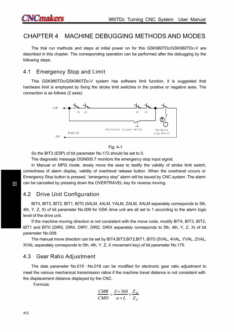
8/17/2019 980TDc CNC Turning Controller User Manual
http://slidepdf.com/reader/full/980tdc-cnc-turning-controller-user-manual 427/461
GSK980TDc Turning CNC System User Manual
412
C onn e c t i on
CHAPTER 4 MACHINE DEBUGGING METHODS AND MODES
The trial run methods and steps at initial power on for this GSK980TDc/GSK980TDc-V are
described in this chapter. The corresponding operation can be performed after the debugging by the
following steps.
4.1 Emergency Stop and Limit
This GSK980TDc/GSK980TDc-V system has software limit function, it is suggested that
hardware limit is employed by fixing the stroke limit switches in the positive or negative axes. The
connection is as follows (2 axes):
Fig. 4-1
So the BIT3 (ESP) of bit parameter No.172 should be set to 0.
The diagnostic message DGN000.7 monitors the emergency stop input signal.
In Manual or MPG mode, slowly move the axes to testify the validity of stroke limit switch,
correctness of alarm display, validity of overtravel release button. When the overtravel occurs or
Emergency Stop button is pressed, “emergency stop” alarm will be issued by CNC system. The alarm
can be cancelled by pressing down the OVERTRAVEL key for reverse moving.
4.2 Drive Unit Configuration
BIT4, BIT3, BIT2, BIT1, BIT0 (5ALM, 4ALM, YALM, ZALM, XALM separately corresponds to 5th,
4th, Y, Z, X) of bit parameter No.009 for GSK drive unit are all set to 1 according to the alarm logic
level of the drive unit.
If the machine moving direction is not consistent with the move code, modify BIT4, BIT3, BIT2,
BIT1 and BIT0 (DIR5, DIR4, DIRY, DIRZ, DIRX separately corresponds to 5th, 4th, Y, Z, X) of bit
parameter No.008.The manual move direction can be set by BIT4,BIT3,BIT2,BIT1, BIT0 (5VAL, 4VAL, YVAL, ZVAL,
XVAL separately corresponds to 5th, 4th, Y, Z, X movement key) of bit parameter No.175.
4.3 Gear Ratio Adjustment
The data parameter No.015~No.018 can be modified for electronic gear ratio adjustment to
meet the various mechanical transmission ratios if the machine travel distance is not consistent with
the displacement distance displayed by the CNC.
Formula:
D
M
Z
Z
LCMD
CMR×
×
×=
α
δ 360

8/17/2019 980TDc CNC Turning Controller User Manual
http://slidepdf.com/reader/full/980tdc-cnc-turning-controller-user-manual 428/461
Chapter 4 Machine Debugging methods and Modes
413
C onn e c t i on
CMR: Code multiplier coefficient (data parameter No.015, No.016, No.146, No.147, No.148)
CMD: Code frequency division coefficient (data parameter No.017, No.018, No.149, No.150,
No.151)
α : Pulse volume, motor rotation angle for a pulse
L: Screw lead
δ: Min. input code unit of CNC(0.001mm for GSK980TDc Z axis, 0.0005mm for X axis of
GSK980TDc)
ZM : gear teeth number of lead screw
ZD: gear teeth number of motor
Example: if gear teeth number of lead is 50, gear teeth number of motor is 30, pulse volume
α =0.075º, screw lead is 4mm,
The electronic gear ratio of X axis is:
The electronic gear ratio of Z axis is:
Then data parameter No.015(CMRX) =1, No.017(CMDX) =1; No.016(CMRZ) =2, No.018(CMDZ)
=1.
If the electronic gear ratio numerator is more than the denominator, the allowed CNC max. speed
will decrease. For example: the data parameter No.016(CMRZ) =2, No.018(CMDZ) =1, so the
allowed Z axis max. speed is 8000mm/min.
If the electronic gear ratio numerator is not equal to the denominator, the allowed CNC
positioning precision may decrease. For example: the data parameter No.016(CMRZ) =1,No.018(CMDZ) =5, so the pulse is not output as the input increment is 0.004, but a pulse is output if
the input increment is 0.005.
In order to ensure the CNC positioning precision and speed index, it is suggested that the CNC
electronic gear ratio is set to 1:1 and the electronic gear ratio calculated is set to the digital servo
when matching with digital servo.
When matching with the step drive, choose the drive unit with step division function as possible
as it can, and properly select mechanical transmission ratio. The 1:1 electronic gear ratio should be
ensured to avoid the excessive difference between the numerator and the denominator of this CNC
electronic gear ratio.
4.4 ACC&DEC Characteristic Adjustment
Adjust the relative CNC parameters according to the factors such as the drive unit, motor
characteristics and machine load:
Data parameter No.022, No.023, 155, 156, 157: X, Z, Y, 4th, 5th axis rapid traverse rate;
Data parameter No.024, No.025, 158, 159, 160: linear ACC&DEC time constant of X, Z,
Y , 4th, 5th axis rapid traverse rate;
Data parameter No.026: X axis exponential ACC&DEC time constant in threading;
Data parameter No.028: Exponential ACC&DEC start/end speed in threading;
Data parameter No.029: Exponential ACC&DEC time constant of cutting and manual feeding;Data parameter No.030: Exponential ACC&DEC start/end speed in cutting feeding;
BIT5 (SMZ) of bit parameter No.007: for smooth transition between cutting feedrates of adjacent
360 0 .0 005 360 50 1
0 .0 75 4 30 1
M
D
Z C M R
C M D L Z
δ
α
× ×
= × = × =
× ×
3 6 0 M
D
Z C M R
C M D L Z
δ
α
×
= ×
×
0.001 360 50 2
0.075 4 30 1
×
= × =
×

8/17/2019 980TDc CNC Turning Controller User Manual
http://slidepdf.com/reader/full/980tdc-cnc-turning-controller-user-manual 429/461
GSK980TDc Turning CNC System User Manual
414
C onn e c t i on
blocks
The larger the ACC&DEC time constant is, the slower the ACC&DEC is, the smaller the machine
movement impact and the lower the machining efficiency is, and vice versa.
If ACC&DEC time constants are equal, the higher the ACC&DEC start/end speed is, the faster
the ACC&DEC is, the bigger the machine movement impact and the higher the machining efficiency
is, and vice versa.
The principle for ACC&DEC characteristic adjustment is to properly reduce the ACC&DEC time
constant and increase the ACC&DEC start/end speed to improve the machining efficiency on the
condition that there is no alarm, motor out-of-step and obvious machine impact. If the ACC&DEC time
constant is set too small, and the start/end speed is set too large, it is easily to cause faults such as
drive unit alarm, motor out-of-step or machine vibration.
When the bit parameter No.007 BIT5(SMZ) =1, the feedrate drops to the start speed of the
ACC&DEC at the cutting path intersection, then it accelerates to the specified speed of the next block
to obtain an accurate positioning at the path intersection, but this will reduce the machining efficiency.
When BIT5=0, the adjacent cutting path transits smoothly by the ACC&DEC. The feedrate does not
always drop to the start speed when the previous path is finished and a circular transition
(non-accurate positioning) will be formed at the path intersection. The machining surface by this path
transition has a good finish and a higher machining efficiency. When the stepper motor drive unit is
applied, the BIT5 of the bit parameter No.007 should be set to 1 to avoid the out-of-step.
When the stepper motor drive unit is applied, the out-of-step may occur on the condition that
rapid traverse speed is too large, ACC&DEC time constant is too small, ACC&DEC start/end speed is
too large. The suggested parameter setting is as follows (the electronic gear ratio 1:1):
Data parameter No.022≤2500 Data parameter No.023≤5000
Data parameter No.155≤5000 Data parameter No.158≥350
Data parameter No.024≥350 Data parameter No.025≥350
Data parameter No.029≥150 Data parameter No.028≤100
Data parameter No.026≥200 Data parameter No.030≤50
If AC servo drive unit is applied to this system, the machining efficiency can be improved by a
larger start speed and a smaller ACC&DEC time constant setting. If optimum acc/dec characteristics
are required, the ACC&DEC time constant may be set to 0 which can be gotten by adjusting the AC
servo acc/dec parameters. The suggested settings for these parameters are as follows(electronic
gear ratio is 1:1):
Data parameter No.022=5000 Data parameter No.023=10000
Data parameter No.155=10000 Data parameter No.158≤60
Data parameter No.024≤60 Data parameter No.025≤60Data parameter No.029≤50 Data parameter No.028≤500
Data parameter No.026≤50 Data parameter No.030≤400
The parameter settings above are recommended for use, please refer to the actual conditions of
the drive unit, motor characteristic and motor load for their proper setting.
4.5 Mechanical (Machine) Zero Adjustment
Adjust the relevant parameters based on the active level of the connection signal, zero return
type and direction applied:
BIT5 (DECI) of the bit parameter No.004: active level of deceleration signal in machine zeroreturn.
BIT0, BIT1, BIT2,BIT3,BIT4 (ZMX, ZMZ, ZMY,ZM4, ZM5) of the bit parameter No.006: X, Z,

8/17/2019 980TDc CNC Turning Controller User Manual
http://slidepdf.com/reader/full/980tdc-cnc-turning-controller-user-manual 430/461
Chapter 4 Machine Debugging methods and Modes
415
C onn e c t i on
Y, 4th, 5th axis machine zero return mode B or C selection.
BIT0, BIT1, BIT2, BIT3, BIT4 (ZCX, ZCZ, ZCY, ZC4, ZC5) of the bit parameter No.007: whether a
proximity switch is taken as both deceleration and zero signals.
BIT2(ZNLK) of the bit parameter No.011: whether the direction key in zero return is self-locked.
BIT0, BIT1, BIT2, BIT3, BIT4(ZRSCX, ZRSCZ, ZRSCY, ZRSC4, ZRSC5) of the bit parameter
No.014: have/not the machine zero(zero turn mode BC/A)setting bit.
Data parameter No.033: low deceleration speeds of each axis in machine zero return.
Data parameter No.113: high speed of each axis in machine zero return.
BIT0, BIT1, BIT2, BIT3, BIT4(MZRX, MZRZ, MZRY, MZR4, MZR5) of the bit parameter No.183:
each axis zero return direction: negative or positive.
Only the stroke limit switch validity is confirmed, can the machine zero return be performed.
The machine zero is usually fixed at the max. travel point, and the effective stroke of the zero
return touch block should be more than 25mm to ensure a sufficient deceleration distance for
accurate zero return. The more rapid the machine zero return is, the longer the zero return touch
block should be. Or the moving carriage will rush over the block and it may affect the zero return
precision because of the insufficient deceleration distance.
Usually there are 2 types of machine zero return connection:
① The connection to AC servo motor: using a travel switch and servo motor one-turn signal
separately
Fig. 4-2
By this connection, when the deceleration switch is released in machine zero return, the one-turn
signal of encoder should be avoided to be at a critical point after the travel switch is released. In order
to improve the zero return precision, and it should ensure the motor reaches the one-turn signal of
encoder after it rotates half circle.
The parameter setting is as follows:
Bit parameter No.004 BIT5(DECI) =0
Bit parameter No.006 BIT0(ZMX) , BIT1(ZMZ) , BIT2(ZMY), BIT3(ZM4), BIT4(ZM5) =0
Bit parameter No.007 BIT0(ZCX) , BIT1(ZCZ) , BIT2(ZCY) , BIT3(ZC4), BIT4(ZC5)=0Bit parameter No.011 BIT2(ZNLK) =1
Bit parameter No.014 BIT0(ZRSCX) , BIT1(ZRSCZ) , BIT2(ZRSCY), BIT3(ZRSC4),
BIT4(ZRSC5) =1
Data parameter No.033=200
Data parameter No.183 BIT0(MZRX) , BIT1(MZRZ) , BIT2(MZRY), BIT3(MZR4) , BIT4(MZR5)
=0
② The connection to stepper motor: schematic diagram of using a proximity switch taken as
both deceleration signal and zero signal

8/17/2019 980TDc CNC Turning Controller User Manual
http://slidepdf.com/reader/full/980tdc-cnc-turning-controller-user-manual 431/461
GSK980TDc Turning CNC System User Manual
416
C onn e c t i on
Fig. 4-3
When matching the stepper motor, it is better to adjust the rapid override to 50% to avoid theout-of-step during rapid traversing of zero return, so the parameter settings are as follows:
Bit parameter No.004 BIT5(DECI) =0
Bit parameter No.006 BIT0(ZMX) , BIT1(ZMZ) , BIT2(ZMY), BIT3(ZM4), BIT4(ZM5) =0
Bit parameter No.007 BIT0(ZCX) , BIT1(ZCZ) , BIT2(ZCY), BIT3(ZC4), BIT4(ZC5) =1
Bit parameter No.011 BIT2(ZNLK) =0
Bit parameter No.014 BIT0(ZRSCX) , BIT1(ZRSCZ) , BIT2(ZRSCY), BIT3(ZRSC4), BIT4(ZRSC5)
=1
Data parameter No.033=200
Data parameter No.183 BIT0(MZRX), BIT1(MZRZ), BIT2(MZRY), BIT3(MZR4), BIT4(MZR5) =0
BIT0~BIT4of diagnosis message DGN.000 are used to check the validity of zero deceleration
signal.
4.6 Spindle Adjustment
4.6.1 Spind le encoder
Encoder with the pulses 100~5000p/r is needed to be installed on the machine for threading. The
pulses are set by data parameter No.70. The transmission ratio(spindle gear teeth/encoder gear teeth)
between encoder and spindle is 1/255~255. The spindle gear teeth are set by CNC data parameter
No.110, and the encoder gear teeth are set by data parameter No.111.Synchronous belt transmission should be applied for it (no sliding transmission).
The BIT3 of diagnosis message DGN.008 are used to check the validity of threads number
signal of the spindle encoder.
The DGN.011 and DNG.012 of diagnosis message are used to check the validity of thread signal
of the spindle encoder.
4.6.2 Spind le brake
After M05 code is executed, proper spindle brake time should be set to stop the spindle promptly
in order to enhance the machining efficiency. If the brake is employed with energy consumption type,
too long braking time may burn out the motor.
Data parameter No.087: delay from spindle stop(M05) to spindle brake output
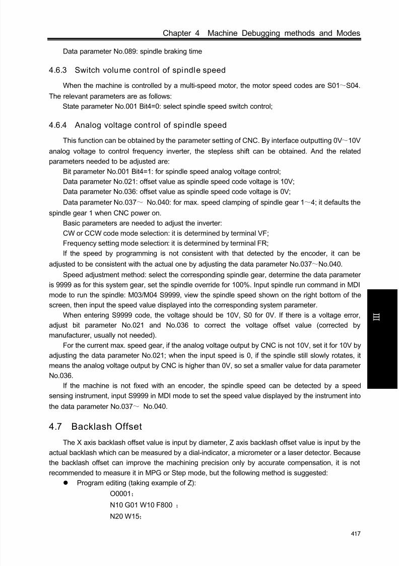
8/17/2019 980TDc CNC Turning Controller User Manual
http://slidepdf.com/reader/full/980tdc-cnc-turning-controller-user-manual 432/461
Chapter 4 Machine Debugging methods and Modes
417
C onn e c t i on
Data parameter No.089: spindle braking time
4.6.3 Switch volume control of spindle speed
When the machine is controlled by a multi-speed motor, the motor speed codes are S01~S04.
The relevant parameters are as follows:State parameter No.001 Bit4=0: select spindle speed switch control;
4.6.4 Analog voltage control of spindle speed
This function can be obtained by the parameter setting of CNC. By interface outputting 0V~10V
analog voltage to control frequency inverter, the stepless shift can be obtained. And the related
parameters needed to be adjusted are:
Bit parameter No.001 Bit4=1: for spindle speed analog voltage control;
Data parameter No.021: offset value as spindle speed code voltage is 10V;
Data parameter No.036: offset value as spindle speed code voltage is 0V;
Data parameter No.037~ No.040: for max. speed clamping of spindle gear 1~4; it defaults the
spindle gear 1 when CNC power on.
Basic parameters are needed to adjust the inverter:
CW or CCW code mode selection: it is determined by terminal VF;
Frequency setting mode selection: it is determined by terminal FR;
If the speed by programming is not consistent with that detected by the encoder, it can be
adjusted to be consistent with the actual one by adjusting the data parameter No.037~No.040.
Speed adjustment method: select the corresponding spindle gear, determine the data parameter
is 9999 as for this system gear, set the spindle override for 100%. Input spindle run command in MDI
mode to run the spindle: M03/M04 S9999, view the spindle speed shown on the right bottom of thescreen, then input the speed value displayed into the corresponding system parameter.
When entering S9999 code, the voltage should be 10V, S0 for 0V. If there is a voltage error,
adjust bit parameter No.021 and No.036 to correct the voltage offset value (corrected by
manufacturer, usually not needed).
For the current max. speed gear, if the analog voltage output by CNC is not 10V, set it for 10V by
adjusting the data parameter No.021; when the input speed is 0, if the spindle still slowly rotates, it
means the analog voltage output by CNC is higher than 0V, so set a smaller value for data parameter
No.036.
If the machine is not fixed with an encoder, the spindle speed can be detected by a speed
sensing instrument, input S9999 in MDI mode to set the speed value displayed by the instrument intothe data parameter No.037~ No.040.
4.7 Backlash Offset
The X axis backlash offset value is input by diameter, Z axis backlash offset value is input by the
actual backlash which can be measured by a dial-indicator, a micrometer or a laser detector. Because
the backlash offset can improve the machining precision only by accurate compensation, it is not
recommended to measure it in MPG or Step mode, but the following method is suggested:
Program editing (taking example of Z):
O0001; N10 G01 W10 F800 ;
N20 W15;
8/17/2019 980TDc CNC Turning Controller User Manual
http://slidepdf.com/reader/full/980tdc-cnc-turning-controller-user-manual 433/461
GSK980TDc Turning CNC System User Manual
418
C onn e c t i on
N30 W1;
N40 W-1;
N50 M30.
Set the backlash error offset to 0 before measuring:
Run the program by single blocks, search the measuring benchmark after 2 positioning
operations, record the current data, move 1mm in the same direction, then move 1mm to
point B reversely, read the current data.
Fig. 4-4 Schematic map of backlash measuring method
Backlash error offset value= | data of point A –data of point B |; then input its outcome to the
data parameter
No.034(BKLX) ,No.035(BKLZ) ,No.180(BKLY) ,No.181(BKL4) ,No.182(BKL5) (multiply X
axis data to 2 and input the outcome to data parameter No.034).
Data A: dial-indicator data at point A
Data B: dial-indicator data at point B
Note 1: The backlash offset mode can be set by Bit7 of CNC parameter No.011; the backlash frequency can
be set by Bi t6 of parameter No.011 and Bi t4, Bit3, Bit2, Bit1, Bit0 of bit parameter No.010.
Note 2: Check the machine backlash every 3 months.
4.8 Tool Post Debugging
GSK980TDc supports various kinds of tool post, and the parameter settings are based on the
machine manual. The parameter settings for the tool post running are as follows:
BIT2(TSGN) of K parameter No.011: high/low level selection of tool post in-position signal, when
the signal is low level active, a parallel pull-up resistor is needed.
Bit3 (CTCP) of K parameter No.011: check/do not check tool post lock signal in tool change;
Bit4 (TCPS)of K parameter No.011: tool post lock signal HIGH/LOW selection;Bit5 (CHET) of K parameter No.11: check/do not check tool signal;
Combinations and functions of tool change mode selection Bit1(CHTB), Bit0(CHTA) of K
parameter No.11 are referred to Tool Change Control .
Data parameter No.076: Duration for moving a tool in tool changing
Data parameter No.078: Upper limit time for changing one tool
Data parameter No.082: Delay time from tool post CCW stop to CW clamping start
Data parameter No.084: Total tools number
Data parameter No.085: Delay of tool post CW clamping
If the tool post doesn’t rotate at first power on for tool change, the phase connection of the
3-phase power of the tool post motor may be incorrect, it needs to press the RESET key immediatelyand cutoff the power, then check the wiring; if the fault is caused by this, exchange two phases of the
3-phase power.
Data reading
position
A
B
Reverse
position
8/17/2019 980TDc CNC Turning Controller User Manual
http://slidepdf.com/reader/full/980tdc-cnc-turning-controller-user-manual 434/461
Chapter 4 Machine Debugging methods and Modes
419
C onn e c t i on
The CW clamping duration setting should be proper, it should be neither longer nor shorter,
longer delay may damage the motor, shorter delay may cause the tool post not to be completely
clamped. The method to check the tool post clamping is: approach the dial-indicator to the tool post,
turn the tool post manually, and the pointer floating of the dial-indicator should not be over 0.01mm.
The BIT7(TL-) and BIT6(TL+) of diagnosis message DGN.005 are used to check the validity of
tool post CCW/CW output signal.
The BIT0~BIT3 (T01~T04) of diagnosis message DGN.000 are used to check the validity of
tool number T01~T04 signal.
During debugging, every tool, max. tools change should be performed to check the correctness
of the tool change, time parameter setting.
4.9 Step/MPG Adjustment
The key on the panel can be used to select the Step mode or MPG mode, which is set by
the BIT3 of bit parameter No.001.Bit3 =1: MPG mode active, Step mode inactive;
=0: Step mode active, MPG mode inactive;

8/17/2019 980TDc CNC Turning Controller User Manual
http://slidepdf.com/reader/full/980tdc-cnc-turning-controller-user-manual 435/461
GSK980TDc Turning CNC System User Manual
420
C onn e c t i on
CHAPTER 5 DIAGNOSIS MESSAGE
Diagnosis messages for GSK980TDc system are described in this chapter.
5.1 CNC Diagnosis
The part is used to check the CNC interface signals and internal running and it can’t be modified.
5.1.1 I/O status and data diagnosis message
0 0 0 ESP *** *** DEC5 DEC4 DECZ DECY DECX
Pin CN61.6 CN61.34 CN61.33 CN61.12 CN61.32 CN61.4
PLC fixed
address
X0.5 X2.5 X2.4 X1.3 X2.3 X0.3
DECX, DECY, DECZ, DEC4, DEC5: machine zero return signal of X, Y, Z, 4th, 5th
ESP: emergency stop signal
0 0 1 *** *** *** *** *** *** *** SKIP
Pin CN61.42
PLC fixed
address
X3.5
SKIP: skip signal
5.1.2 CNC motion state and data diagnosis message
0 0 3 *** *** *** RDY5 RDY4 RDYZ RDYY RDYX
RDY5~RDYX: X, Y, Z, 4th, 5th ready signal
0 0 4 *** *** *** EN5 EN4 ENZ ENY ENX
EN5~ENX: enabling signal
0 0 5 *** *** *** SET5 SET4 SETZ SETY SETX
SET5~SETX: pulse prohibit signal
0 0 6 *** *** *** DRO5 DRO4 DROZ DROY DROX
DRO5~DROX: X, Y, Z, 4th, 5th motion direction output
0 0 8 *** *** *** PC5 PC4 PCZ PCY PCX
PC5~PCX: X, Y, Z, 4th, 5th zero signal
0 0 9 *** *** *** ALM5 ALM4 ALMZ ALMY ALMX
ALM5~ ALMX: X, Y, Z, 4th, 5th alarm signal
0 1 0 MPG rotation data

8/17/2019 980TDc CNC Turning Controller User Manual
http://slidepdf.com/reader/full/980tdc-cnc-turning-controller-user-manual 436/461
Chapter 5 Diagnosis Message
421
C onn e c t i on
0 1 1 Spindle speed feedback data
0 1 2 Spindle speed maximum feedback data
0 1 3 Spindle 1 analog output value
0 1 4 Spindle 2 analog output value
0 4 8 X axis output pulse number
0 4 9 X axis actual output pulse number (FPGA actual output)0 5 0 Y axis output pulse number
0 5 1 Y axis actual output pulse number (FPGA actual output)
0 5 2 Z axis output pulse number
0 5 3 Z axis actual output pulse number (FPGA actual output)
0 5 4 4 axis output pulse number
0 5 5 4 axis actual output pulse number (FPGA actual output)
0 5 6 5 axis output pulse number
0 5 7 5 axis actual output pulse number (FPGA actual output)
0 6 7 Spindle encoder counting
0 6 8 MPG counting
0 6 9 The pulse number from the time that X axis starts detecting PC signal tPC signal is detected
0 7 0The pulse number from the time that Y axis starts detecting PC signal t
PC signal is detected
0 7 1The pulse number from the time that Z axis starts detecting PC signal t
PC signal is detected
0 7 2The pulse number from the time that 4 axis starts detecting PC signal
to PC signal is detected
0 7 3The pulse number from the time that 5 axis starts detecting PC signal
to PC signal is detected
0 7 4 The times of system powering off
0 7 5 The times of system undervoltage (when the power is not off)
0 7 6The times of insufficient time for data saving when the system is
undervoltage
5.1.3 Diagnosis keys
DGN.016~DGN.022 are the diagnosis messages of edit keypad keys; DGN.024~DGN.029 are
the diagnosis messages of machine operation panel keys. When pressing a key in the operation
panel, the corresponding bit displays “1”, and “0” after releasing this key. If it displays reversely, it
means there is a fault in the keypad circuit.
0 1 6 RST O N G P/Q 7 8 9Key
0 1 7 PGU X Z U W 4 5 6
Key
0 1 8 PGD H/Y F/E R/V D/L 1 2 3
Key
0 1 9 CRU RIGHT I/A J/B K/C - 0 .

8/17/2019 980TDc CNC Turning Controller User Manual
http://slidepdf.com/reader/full/980tdc-cnc-turning-controller-user-manual 437/461
GSK980TDc Turning CNC System User Manual
422
C onn e c t i on
Key
0 2 0 CRD LEFT M S T EOB INS/ALT DEL
Key
0 2 1 IN OUT CHG /,# CAN
Key
0 2 2 POS RPG OFT ALM SET PAR DGN GRA
Key
0 2 3 FLEFT F1 F2 F3 F4 F5 FRIGHT PLC
Key
5.1.4 Others
0 7 1 BOOT version No.
1 1 8 PLC execution time(ms)
1 1 9 Execution all time (h)
0 2 1 IN OUT CHG /,# CAN
Key
0 2 2 POS RPG OFT ALM SET PAR DGN GRA
Key
0 2 3 FLEFT F1 F2 F3 F4 F5 FRIGHT PLC
Key
5.2 PLC State
This part of diagnosis is used to detect the signal state of machine→PLC(X), PLC→machine(Y),
CNC→PLC (F), PLC→CNC (G) and alarm address A, and internal relay (R, K) states.
5.2.1 X address (machine→PLC , defined by standard PLC ladders)
X0000 T05 PRES ESP DITW DECX DIQP SP SAGT
T05: tool signal T05
PRES: pressure check input signal
ESP: emergency stop signal
DITW: tailstock control input

8/17/2019 980TDc CNC Turning Controller User Manual
http://slidepdf.com/reader/full/980tdc-cnc-turning-controller-user-manual 438/461
Chapter 5 Diagnosis Message
423
C onn e c t i on
DECX: X deceleration signal
DIQP: chuck control input
SP: external pause
SAGT: safety door check signal
X0001 T01 M42I M41I ST DECZ T08/CHOT T07/INDX T06/SELE
T01: tool signal T01
M42I: spindle automatic gear shifting 2-gear in-position signal
M41I: spindle automatic gear shifting 1-gear in-position signal
ST: external cycle start
DECZ: Z deceleration signal
T08/CHOT: tool signal T08/tool post worktable overheat
T07/INDX: tool signal T07/Yantai tool post pregraduation input
T06/SELE: tool signal T06/Yantai tool post strobe signal
X0002 AEY/BDT TCP DEC5 DEC4 DECY T04 T03 T02
AEY/BDT: external skip
TCP: tool post clamp signal
DEC5: 5th deceleration signal
DEC4: 4th deceleration signal
DECY: Y deceleration signal
T04: tool signal T04
T03: tool signal T03
T02: tool signal T02
X0003 AEZ AEX SKIP NQPJ WQPJ LMIZ LMIY LMIX
AEZ: G37 skip signal
AEX: G36 skip signal
SKIP: G31 skip signal
NQPJ: inner chuck clamp/outer chuck clamp in-position signal
WQPJ: inner chuck release/outer chuck clamp in-position signal
LMIZ: Z overtravel input
LMIY: Y overtravel input
LMIX: X overtravel input
X0005 *** *** *** *** SALM COIN SAR VPOSALM: spindle abnormality alarm input
COIN: spindle orientation completion signal
SAR: spindle speed arrival
VPO: spindle position/speed control state
X0006 *** *** ×100 ×10 ×1 ZHAN YHAN XHAN
×100: increment ×100(external)
×10: increment×10(external)
×1: increment×1(external)
ZHAN: Z selection(external)
YHAN: Y selection(external)

8/17/2019 980TDc CNC Turning Controller User Manual
http://slidepdf.com/reader/full/980tdc-cnc-turning-controller-user-manual 439/461
GSK980TDc Turning CNC System User Manual
424
C onn e c t i on
XHAN: X selection(external)
5.2.2 Y address (PLC→machine, defined by s tandard PLC ladders)
Y0000 SPZD SCLP M05 M04 M03 *** M32 COOL
SPZD: spindle brakeSCLP: spindle clamped
M05: spindle stop
M04: spindle rotation CCW
M03: spindle rotation CW
M32: lubricating output
COOL: cooling output
Y0001 TL- TL+ DOQPS DOQPJ S4/M44 S3/M43 S42/M42 S41/M41
TL-: TL-tool post rotation (CW)
TL+: TL+tool post rotation(CCW)DOQPS: chuck release
DOQPJ: chuck clamp
S4/M44: spindle mechanical 4-gear
S3/M43: spindle mechanical 3-gear
S2/M42: spindle mechanical 2-gear
S1/M41: spindle mechanical 1-gear
Y0002 VP2 DOTWS DOTWJ CLPR CLPG CLPY INDXS TZD
VP2: the 2nd spindle speed/position switch output
DOTWS: tailstock going backwardDOTWJ: tailstock going forward
CLPR: three-color lamp-red
CLPG: three-color lamp-green
CLPY: three-color lamp-yellow
INDXS: tool post worktable pregraduation coil
TZD: tool post worktable brake
Y0003 UO5/SP2 UO4/SP1 UO3/SP0 U2/M64/STAO U1/M63 U0/TAP2 HPS
T
SVF
UO5/SP2: user macro output 5/orientation position 2UO4/SP1: user macro output 4/orientation position 1
UO3/SP0: user macro output 3/orientation position 0
U2/M64/STAO: user macro output 2/the 2nd spindle CCW/orientation start signal
U1/M63: user macro output 1/the 2nd spindle CW
U0/TAP2: user macro output 0/the 2nd gain selection signal of the 2nd spindle speed loop(rigid
tapping)
HPST: hydraulic control output
SVF: spindle servo OFF (reduce the spindle servo excitation)
Y0005 *** *** *** *** SRV SFR TAP VP
SRV: spindle rotation(CW)

8/17/2019 980TDc CNC Turning Controller User Manual
http://slidepdf.com/reader/full/980tdc-cnc-turning-controller-user-manual 440/461
Chapter 5 Diagnosis Message
425
C onn e c t i on
SFR: spindle rotation(CCW)
TAP: the 2nd gain selection signal of the spindle speed loop
VP: spindle position/speed control switch output
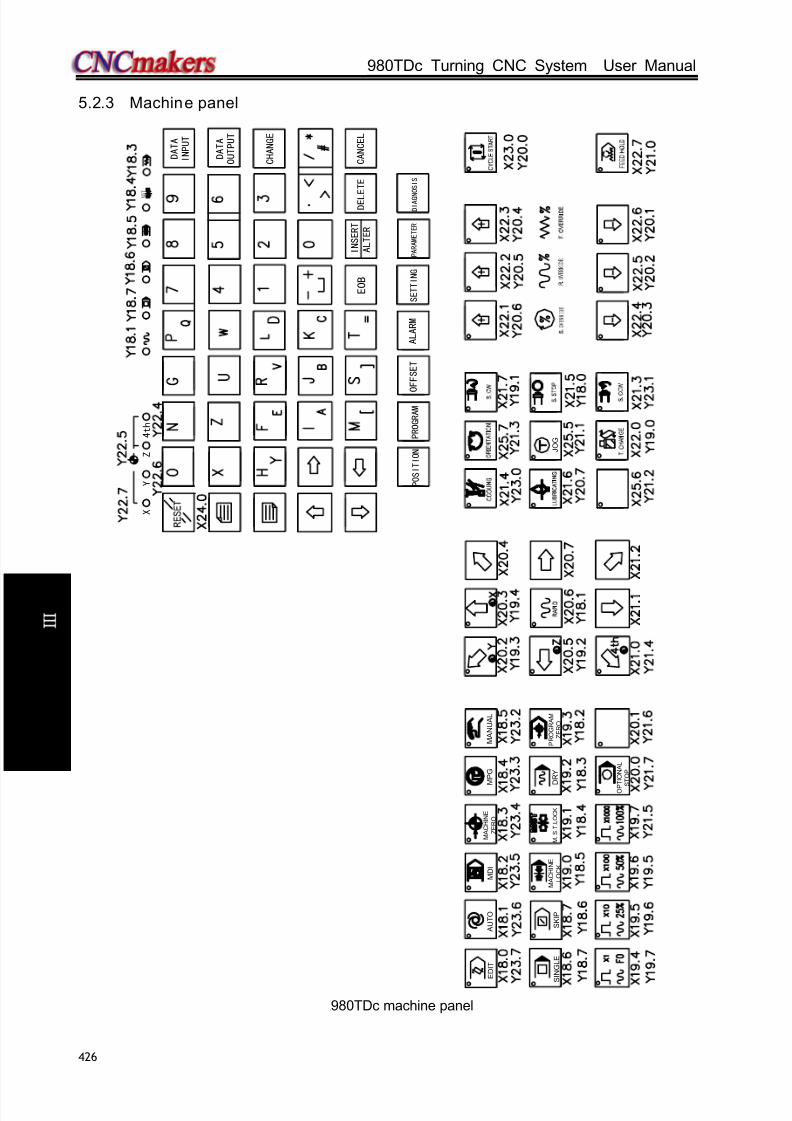
8/17/2019 980TDc CNC Turning Controller User Manual
http://slidepdf.com/reader/full/980tdc-cnc-turning-controller-user-manual 441/461
GSK980TDc Turning CNC System User Manual
426
C onn e c t i on
5.2.3 Machine panel
A U T O
M A C H I N E
L O C K
M D I
M .
S . T . L O C K
M A C H I N E
Z E R O
O P T I O N A L
S
T O P
M P G
P R O G R A M
Z E R O
M A N U A L
D I A G N
O S I S
D E L
E T E
C A N C E L
C H A N G E
O U T P U T
I N P U T
D A T A
P A R A M E T E R
A L T E R
E O B
A L A R M
S E T T I N G
M
S T
D A T A
J O G
P R O G R A M
P O S I T I O N
D R Y
S K I P
S
I N G L E
E D I T
4 t h
Z
X
Y
O F F S E T
I N S E R T
GSK980TDc machine panel

8/17/2019 980TDc CNC Turning Controller User Manual
http://slidepdf.com/reader/full/980tdc-cnc-turning-controller-user-manual 442/461
Chapter 5 Diagnosis Message
427
C onn e c t i on
TOOL NO.GEAR
GRAPHIC
AUTO
MACHINE LOCK
MDI
M.S.T.LOCK
MACHINE
ZERO
OPTIONAL
STOP
MPGPROGRAM
ZEROMANUAL
DIAGNOSIS
DELETE CANCEL
CHANGE
OUTPUT
INPUT
DATA
PARAMETER
ALTEREOB
ALARM SETTING
DATA
JOG
PROGRAMPOSITION
DRYSKIPSINGLE
EDIT
OFFSET
INSERT
GSK980TDc-V machine panel
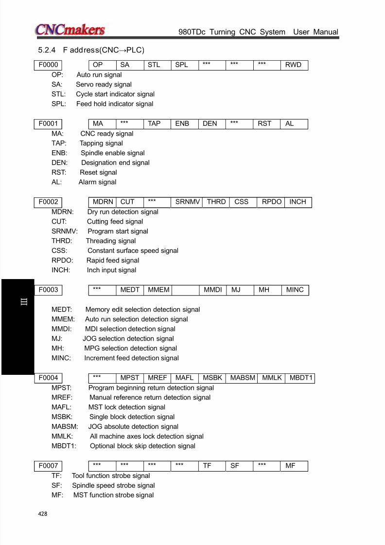
8/17/2019 980TDc CNC Turning Controller User Manual
http://slidepdf.com/reader/full/980tdc-cnc-turning-controller-user-manual 443/461
GSK980TDc Turning CNC System User Manual
428
C onn e c t i on
5.2.4 F address(CNC→PLC)
F0000 OP SA STL SPL *** *** *** RWD
OP: Auto run signal
SA: Servo ready signal
STL: Cycle start indicator signalSPL: Feed hold indicator signal
F0001 MA *** TAP ENB DEN *** RST AL
MA: CNC ready signal
TAP: Tapping signal
ENB: Spindle enable signal
DEN: Designation end signal
RST: Reset signal
AL: Alarm signal
F0002 MDRN CUT *** SRNMV THRD CSS RPDO INCH
MDRN: Dry run detection signal
CUT: Cutting feed signal
SRNMV: Program start signal
THRD: Threading signal
CSS: Constant surface speed signal
RPDO: Rapid feed signal
INCH: Inch input signal
F0003 *** MEDT MMEM MMDI MJ MH MINC
MEDT: Memory edit selection detection signal
MMEM: Auto run selection detection signal
MMDI: MDI selection detection signal
MJ: JOG selection detection signal
MH: MPG selection detection signal
MINC: Increment feed detection signal
F0004 *** MPST MREF MAFL MSBK MABSM MMLK MBDT1
MPST: Program beginning return detection signal
MREF: Manual reference return detection signal
MAFL: MST lock detection signal
MSBK: Single block detection signal
MABSM: JOG absolute detection signal
MMLK: All machine axes lock detection signal
MBDT1: Optional block skip detection signal
F0007 *** *** *** *** TF SF *** MF
TF: Tool function strobe signalSF: Spindle speed strobe signal
MF: MST function strobe signal

8/17/2019 980TDc CNC Turning Controller User Manual
http://slidepdf.com/reader/full/980tdc-cnc-turning-controller-user-manual 444/461
Chapter 5 Diagnosis Message
429
C onn e c t i on
F0009 DM00 DM01 DM02 DM30 *** *** *** ***
DM00: M decoding signal
DM01: M decoding signal
DM02: M decoding signal
DM30: M decoding signal
F0010 MB07 MB06 MB05 MB04 MB03 MB02 MB01 MB00F0011 MB15 MB14 MB13 MB12 MB11 MB10 MB09 MB08F0012 MB23 MB22 MB21 MB20 MB19 MB18 MB17 MB16F0013 MB31 MB30 MB29 MB28 MB27 MB26 MB25 MB24
Miscellaneous function codes MB00~MB31
F0022 SB07 SB06 SB05 SB04 SB03 SB02 SB01 SB00F0023 SB15 SB14 SB13 SB12 SB11 SB10 SB09 SB08F0024 SB23 SB22 SB21 SB20 SB19 SB18 SB17 SB16
F0025 SB31 SB30 SB29 SB28 SB27 SB26 SB25 SB24Spindle speed code signal SB00~SB31
F0026 TB07 TB06 TB05 TB04 TB03 TB02 TB01 TB00F0027 TB15 TB14 TB13 TB12 TB11 TB10 TB09 TB08F0028 TB23 TB22 TB21 TB20 TB19 TB18 TB17 TB16F0029 TB31 TB30 TB29 TB28 TB27 TB26 TB25 TB24
Tool function code signal TB00~TB31
F0036 R08O R07O R06O R05O R04O R03O R02O R01OF0037 *** *** *** *** R12O R11O R10O R09O
S12 bit code signal R01O~R12O
F0054 UO07 UO06 UO05 UO04 UO03 UO02 UO01 UO00F0055 UO15 UO14 UO13 UO12 UO11 UO10 UO09 UO08
Macro output signal UO00~UO15
F0056 U107 U106 U105 U104 U103 U102 U101 U100F0057 U115 U114 U113 U112 U111 U110 U109 U108F0058 U123 U122 U121 U120 U119 U118 U117 U116F0059 U131 U130 U129 U128 U127 U126 U125 U124
Macro output signal U100~131
F0064 *** *** *** *** *** *** TLNW TLCH
TLNW: New tool selection signal (for tool life management)TLCH: Tool change signal(for tool life management)
F0065 *** *** *** *** *** *** RGSPM RGSPPRGSPM: Spindle CCW rotation (in rigid tapping)RGSPP: Spindle CW rotation (in rigid tapping)
F0076 *** *** *** *** RTAP *** *** ***RTAP: rigid tapping method signal
F0091 *** *** *** *** MMMOD *** *** ***MMMOD: Mode signal; it informs system of the manual trial cut mode;

8/17/2019 980TDc CNC Turning Controller User Manual
http://slidepdf.com/reader/full/980tdc-cnc-turning-controller-user-manual 445/461
GSK980TDc Turning CNC System User Manual
430
C onn e c t i on
F0094 *** *** *** ZP5 ZP4 ZP3 ZP2 ZP1
ZP5: Reference point return end signal ZP5
ZP4: Reference point return end signal ZP4
ZP3: Reference point return end signal ZP3
ZP2: Reference point return end signal ZP2
ZP1: Reference point return end signal ZP1
F0102 *** *** *** MV5 MV4 MV3 MV2 MV1
MV5: Axis move signal MV5
MV4: Axis move signal MV4
MV3: Axis move signal MV3
MV2: Axis move signal MV2
MV1: Axis move signal MV1
F0106 *** *** *** MVD5 MVD4 MVD3 MVD2 MVD1
MVD5 Axis move direction signal MVD5
MVD4: Axis move direction signal MVD4
MVD3: Axis move direction signal MVD3
MVD2: Axis move direction signal MVD2
MVD1: Axis move direction signal MVD1
F0120 *** *** *** ZRF5 ZRF4 ZRF3 ZRF2 ZRF1
ZRF5: Reference point creation signal ZRF5
ZRF4: Reference point creation signal ZRF4
ZRF3: Reference point creation signal ZRF3ZRF2: Reference point creation signal ZRF2
ZRF1: Reference point creation signal ZRF1
F0129 *** *** *** *** *** *** *** KEAXSLKEAXSL: PLC axis control status selection signal
F0130 EBSYA *** *** EGENA EDENA *** *** ***EBSYA: PLC axis control group A command read completed signalEGENA: PLC axis control group A axis movement signalEDENA: PLC axis control group A auxiliary function implement signal
F0131 *** *** *** *** *** *** EABUFA EMFAEABUFA: PLC axis control group A buffer full signalEMFA: PLC axis control group A auxiliary function strobe signal
F0132 EM28A EM24A EM22A EM21A EM18A EM14A EM12A EM11APLC axis control group A auxiliary function code signals EM11A~EM28A
F0133 EBSYB *** *** EGENB EDENB *** *** ***EBSYB: PLC axis control group B command read completed signalEGENB: PLC axis control group B axis movement signalEDENB: PLC axis control group B auxiliary function implement signal
F0134 *** *** *** *** *** *** EABUFB EMFBEABUFB: PLC axis control group B buffer full signalEMFB: PLC axis control group B auxiliary function strobe signal

8/17/2019 980TDc CNC Turning Controller User Manual
http://slidepdf.com/reader/full/980tdc-cnc-turning-controller-user-manual 446/461
Chapter 5 Diagnosis Message
431
C onn e c t i on
F0135 EM28B EM24B EM22B EM21B EM18B EM14B EM12B EM11B
PLC axis control group A auxiliary function code signals EM11B~EM28B
F0136 EBSYC *** *** EGENC EDENC *** *** ***EBSYC: PLC axis control group C command read completed signal
EGENC: PLC axis control group C axis movement signalEDENC: PLC axis control group C auxiliary function implement signal
F0137 *** *** *** *** *** *** EABUFC EMFCEABUFC: PLC axis control group C buffer full signalEMFC: PLC axis control group C auxiliary function strobe signal
F0138 EM28C EM24C EM22C EM21C EM18C EM14C EM12C EM11CPLC axis control group A auxiliary function code signals EM11C~EM28C
F0139 EBSYD *** *** EGEND EDEND *** *** ***EBSYD: PLC axis control group D command read completed signal
EGEND: PLC axis control group D axis movement signalEDEND: PLC axis control group D auxiliary implement signal
F0140 *** *** *** *** *** *** EABUFD EMFDEABUFD: PLC axis control group D buffer full signalEMFD: PLC axis control group D auxiliary function strobe signal
F0141 EM28D EM24D EM22D EM21D EM18D EM14D EM12D EM11DPLC axis control group A auxiliary function code signals EM11D~EM28D
F0142 EM48A EM44A EM42A EM41A EM38A EM34A EM32A EM31APLC axis control group A auxiliary function code signals EM31A~EM48A
F0145 EM48B EM44B EM42B EM41B EM38B EM34B EM32B EM31BPLC axis control group B auxiliary function code signals EM3BA~EM48B
F0148 EM48C EM44C EM42C EM41C EM38C EM34C EM32C EM31CPLC axis control group C auxiliary function code signals EM31C~EM48C
F0151 EM48D EM44D EM42D EM41D EM38D EM34D EM32D EM31DPLC axis control group D auxiliary function code EM31D~EM48D
F0182 *** *** *** EACNT5 EACNT4 EACNT3 EACNT2 EACNT1EACNT5: PLC axis control 5th axis control signal
EACNT4: PLC axis control 4th axis control signalEACNT3: PLC axis control Y axis control signalEACNT2: PLC axis control Z axis control signalEACNT1: PLC axis control X axis control signal
F0198 *** *** *** PRO5 PRO4 PRO3 PRO2 PRO1
PRO4: Program zero return end signal PRO5
PRO4: Program zero return end signal PRO4
PRO3: Program zero return end signal PRO3
PRO2: Program zero return end signal PRO2
PRO1: Program zero return end signal PRO1
F0199 *** *** *** *** *** *** *** MSPHD

8/17/2019 980TDc CNC Turning Controller User Manual
http://slidepdf.com/reader/full/980tdc-cnc-turning-controller-user-manual 447/461
GSK980TDc Turning CNC System User Manual
432
C onn e c t i on
MSPHD: Spindle JOG detection signal
F0200 *** *** *** SIMSPL *** *** *** ***
SIMSPL: Analog spindle active
F0201 *** *** DECI *** *** DCS *** ***
DECI: DEC signal level selection in reference return
DCS: If OUT key may start program in MDI mode
F0205 *** *** *** *** *** ZNIK *** ***
ZNIK: Axis move key hold active in zero return
F0210 *** MST MSP *** MESP *** SINC SOVI
MST: Shield external cycle start signal
MSP: Shield external feed hold signal
MESP: Shield external emergency stop signal
F0212 *** *** *** COVL CINP CDWL *** ***
COVL: Bit check being executed
CINP: G04 code being executed
CDWL: RS232 interface being receiving
F0213 *** *** *** *** *** *** CTRD CTPU
CTRD: RS232 interface being transmitting
CTPU: Spindle jog/lubricating selection
F0214 *** *** *** VAL5 VAL4 VALY ZVAL XVAL
VAL5: 5th axis direction selection
VAL4: 4th axis direction selection
VALY: Y direction selection
VALZ: Z direction selection
VALX: X direction selection
5.2.5 G address (PLC→CNC)
G0004 *** *** *** *** FIN *** *** ***
FIN: MST function end signal
G0005 *** AFL *** *** *** *** *** ***
AFL: MST lock signal
SFIN: Spindle S function end signal
G0006 *** SKIPP *** OVC *** ABSM *** SRN
OVC: Feedrate override cancel signal
SRN: Program restart signal
G0007 RLSOT EXLM *** *** *** ST STLK ***
ST: Cycle start signal

8/17/2019 980TDc CNC Turning Controller User Manual
http://slidepdf.com/reader/full/980tdc-cnc-turning-controller-user-manual 448/461
Chapter 5 Diagnosis Message
433
C onn e c t i on
G0008 ERS RRW SP ESP *** *** *** IT
ERS: External reset signal
RRW: Reset and cursor return signal
SP: Feed hold signal
ESP: Emergency stop signal
G0010 JV07 JV06 JV05 JV04 JV03 JV02 JV01 JV00G0011 JV15 JV14 JV13 JV12 JV11 JV10 JV09 JV08
JOG override signal JV00~JV15
G0012 FV07 FV06 FV05 FV04 FV03 FV02 FV01 FV00Feedrate override signal FV00~FV07
G0014 *** *** *** *** *** *** RV2 RV1
RV2: Rapid feedrate override signal RV2
RV1: Rapid feedrate override signal RV1
G0018 *** *** *** *** HD HC HB HA
HD: MPG feed selection signal (01004th)
HC MPG feed selection signal (01015th)
HB: MPG feed selection signal (0011Y)
HA: MPG feed selection signal (0001X. 0010Z)
G0019 RT *** MP2 MP1 *** *** *** ***
RT: Manual rapid feed selection signal
MP2: MPG override signal MP2
MP1: MPG override signal MP1
G0027 CON *** *** SSTP2 SSTP1 *** SWS2 SWS1CON: Cs contouring control switch signalSSTP2: 2nd spindle stop signal (for multi-spindle function)SSTP1: 1st spindle stop signal (for multi-spindle function)SWS2: Multi-spindle selection signal 2SWS1: Multi-spindle selection signal 1
G0028 *** *** *** *** *** GR2 GR1 ***
GR2: Gear selection signalGR1: Gear selection signal
G0029 *** KSSTP *** SAR *** *** *** ***
KSSTP: spindle stop signal
SAR: spindle speed arrival
GR22: 2nd spindle gear selection signal 2 (for multi-spindle function)GR21: 2nd spindle gear selection signal 1 (for multi-spindle function)
G0030 SOV7 SOV6 SOV5 SOV4 SOV3 SOV2 SOV1 SOV0
SOV7: 2nd Spindle override signal SOV7
SOV6: 2nd Spindle override signal SOV6

8/17/2019 980TDc CNC Turning Controller User Manual
http://slidepdf.com/reader/full/980tdc-cnc-turning-controller-user-manual 449/461
GSK980TDc Turning CNC System User Manual
434
C onn e c t i on
SOV5: 2nd Spindle override signal SOV5
SOV4: 2nd Spindle override signal SOV4
SOV3: 1st Spindle override signal SOV3
SOV2: 1st Spindle override signal SOV2
SOV1: 1st Spindle override signal SOV1
SOV0: 1st Spindle override signal SOV0
G0032 R08I R07I R06I R05I R04I R03I R02I R01I
R08I: Spindle motor speed code signal R08I
R07I: Spindle motor speed code signal R07I
R06I: Spindle motor speed code signal R06I
R05I: Spindle motor speed code signal R05I
R04I: Spindle motor speed code signal R04I
R03I: Spindle motor speed code signal R03I
R02I: Spindle motor speed code signal R02I
R01I: Spindle motor speed code signal R01I
G0033 SIND *** *** *** R12I R11I R10I R09I
R09I: Spindle motor speed code signal R09I
R10I: Spindle motor speed code signal R10I
R11I: Spindle motor speed code signal R11I
R12I: Spindle motor speed code signal R12I
SGN: Spindle motor code polarity selection signal
SIND: Spindle motor speed code selection signal
G0043 ZRN *** DNC1 *** *** MD4 MD2 MD1
MD1: Current mode selection 1
MD2: Current mode selection 2
MD4: Current mode selection 3
DNC1: DNC selection signal
ZRN: Current mode selection 4
G0044 HDT *** *** *** *** *** MLK BDT
BDT: Block skip signal (PLC→CNC)
MLK: Machine lock signal(PLC→CNC)HDT: Manual tool change signal
G0046 DRN *** *** *** KEY1 *** SBK ***
SBK: Single block signal (PLC→CNC)
KEY1: Memory protection signal
DRN: Dry run signal
G0054 UI07 UI06 UI05 UI04 UI03 UI02 UI01 UI00
UI00: Macro input signal UI00
UI01: Macro input signal UI01
UI02: Macro input signal UI02
UI03: Macro input signal UI03

8/17/2019 980TDc CNC Turning Controller User Manual
http://slidepdf.com/reader/full/980tdc-cnc-turning-controller-user-manual 450/461
Chapter 5 Diagnosis Message
435
C onn e c t i on
UI04: Macro input signal UI04
UI05: Macro input signal UI05
UI06: Macro input signal UI06
UI07: Macro input signal UI07
G0055 UI15 UI14 UI13 UI12 UI11 UI10 UI09 UI08
UI08: Macro input signal UI08
UI09: Macro input signal UI09
UI10: Macro input signal UI10
UI11: Macro input signal UI11
UI12: Macro input signal UI12
UI13: Macro input signal UI13
UI14: Macro input signal UI14
UI15: Macro input signal UI15
G0061 *** *** RGTSP2 RGTSP1 *** *** *** RGTAP
RGTAP: Rigid tapping signal
RGTSP1: Spindle selection in rigid tapping RGTSP1
RGTSP2: Spindle selection in rigid tapping RGTSP2
G0074 *** *** SRVB SFRB *** *** *** ***
SFRB: Spindle CCW signal in rigid tapping
SRVB: Spindle CW signal in rigid tapping
G0100 *** *** *** +J5 +J4 +J3 +J2 +J1 +J1: Feed axis and direction selection signal +J1
+J2: Feed axis and direction selection signal +J2
+J3: Feed axis and direction selection signal +J3
+J4: Feed axis and direction selection signal +J4
+J5: Feed axis and direction selection signal +J5
G0102 *** *** *** -J5 -J4 -J3 -J2 -J1
-J1: Feed axis and direction selection signal -J1
-J2: Feed axis and direction selection signal -J2
-J3: Feed axis and direction selection signal -J3-J4: Feed axis and direction selection signal -J4
-J5: Feed axis and direction selection signal –J5
G0114 *** *** *** +L5 +L4 +L3 +L2 +L1
+L1: Axis overtravel signal +L1
+L2: Axis overtravel signal +L2
+L3: Axis overtravel signal +L3
+L4: Axis overtravel signal +L4
+L5: Axis overtravel signal +L5
G0116 *** *** *** -L5 -L4 -L3 -L2 -L1
-L1: Axis overtravel signal -L1

8/17/2019 980TDc CNC Turning Controller User Manual
http://slidepdf.com/reader/full/980tdc-cnc-turning-controller-user-manual 451/461
GSK980TDc Turning CNC System User Manual
436
C onn e c t i on
-L2: Axis overtravel signal -L2
-L3: Axis overtravel signal -L3
-L4: Axis overtravel signal -L4
-L5: Axis overtravel signal –L5
G0200 *** *** *** *** *** *** *** SPD
SPD Spindle jog signal
G0201 NT07 NT06 NT05 NT04 NT03 NT02 NT01 NT00
NT00: Current tool No. NT00
NT01: Current tool No. NT01
NT02: Current tool No. NT02
NT03: Current tool No. NT03
NT04: Current tool No. NT04
NT05: Current tool No. NT05
NT06: Current tool No. NT06
NT07: Current tool No. NT07
G0202 NT15 NT14 NT13 NT12 NT11 NT10 NT09 NT08
NT08: Current tool No. NT08
NT09: Current tool No. NT09
NT10: Current tool No. NT10
NT11: Current tool No. NT11
NT12: Current tool No. NT12
NT13: Current tool No. NT13NT14: Current tool No. NT14
NT15: Current tool No. NT15
G0203 NT23 NT22 NT21 NT20 NT19 NT18 NT17 NT16
NT16: Current tool No. NT16
NT17: Current tool No. NT17
NT18: Current tool No. NT18
NT19: Current tool No. NT19
NT20: Current tool No. NT20
NT21: Current tool No. NT21NT22: Current tool No. NT22
NT23: Current tool No. NT23
G0204 NT31 NT30 NT29 NT28 NT27 NT26 NT25 NT24
NT24: Current tool No. NT24
NT25: Current tool No. NT25
NT26: Current tool No. NT26
NT27: Current tool No. NT27
NT28: Current tool No. NT28
NT29: Current tool No. NT29
NT30: Current tool No. NT30
NT31: Current tool No. NT31

8/17/2019 980TDc CNC Turning Controller User Manual
http://slidepdf.com/reader/full/980tdc-cnc-turning-controller-user-manual 452/461
Chapter 5 Diagnosis Message
437
C onn e c t i on
5.2.6 Address A (message display requiery signal, defined by standard PLC
ladders)
Address Alarm No. Content
A0000.0 1000 Tool change too long A0000.1 1001 Tool post not in-position alarm as tool change ends
A0000.2 1002 Tool change unfinished alarm
A0000.3 1003 Tool post clamping signal not received
A0000.4 1004Recheck clamping signal, and clamping signal inactive as tool
change ends
A0000.5 1005 Tool change execution is mistaken before power off
A0000.6 1006 Pre-indexing proximity switch not arrived
A0000.7 1007 Tool post overheat alarm
A0001.0 1008 M10 and M11 codes disabled for tailstock function inactive
A0001.1 1009 Run-out disabled in spindle running A0001.3 1011 Spindle start unallowed as tailstock advancing not detected
A0001.4 1012 Cycle unallowed for cycle start disabled
A0001.5 1013 Spindle start unallowed for spindle enable off
A0001.6 1014 Confirm the tools of tool post (8, 10, 12 tools)
A0002.0 1014 Please reset BIT1, BIT0 of parameter 168 for tool post model
A0002.1 1016 Alarm of safe door not closed
A0002.3 1017 Alarm of chuck low pressure
A0002.4 1019 Chuck released unallowed in spindle running
A0002.5 1020 Clamping in-position signal inactive alarm in spindle running
A0002.6 1021Spindle start unallowed if chuck clamping in-position signal
inactive
A0003.0 1022 Spindle start unallowed for chuck releasing
A0003.0 1024 M12/M13 code disabled as chuck inactive
A0003.1 1025 Has not checked the chuck clamped/released start signal
A0003.3 1027 The tool pot is not released
A0003.4 1028 Has not found the target tool
A0003.5 1029 Has not received tool pot stop and locking start signal
A0003.7 1031Total tools is more than 4, and the external override cannot be
connected A0004.1 1032 Illegal M code
A0004.2 1033 Spindle jog disabled in non-analog spindle mode
A0004.3 1035 M63, M64 designation error
A0004.4 1036 Spindle gear change time is too long
A0004.5 1037 Spindle speed/position control switch time is too long
A0004.6 1038 The 2nd spindle speed/position control switch time is too long
A0004.7 1039 Spindle position control does not permit the orientation
A0005.0 1040 Spindle orientation time is too long
A0005.11041
Alarm for the abnormal spindle servo or frequency converter for
abnormality A0005.2 1042 Alarm for the abnormal 2nd spindle servo or frequency converter
A0005.3 1043 Forbid clamping the spindle when the spindle rotating or feeding

8/17/2019 980TDc CNC Turning Controller User Manual
http://slidepdf.com/reader/full/980tdc-cnc-turning-controller-user-manual 453/461
GSK980TDc Turning CNC System User Manual
438
C onn e c t i on
Address Alarm No. Content
A0005.4 1044 Spindle is clamped not to rotate or feed
A0007.0 2000 Hydraulic motor is not started
A0007.1 2001 Safety door has been opened
A0007.3 2003 Alarm for the tool pot unclocked
5.2.7 K address K parameter, standard PLC defin ition)
RRW =1: the cursor returning to the head of the program in any working modes when the
system resets is valid;
=0: the cursor returning to the head of the program in edit mode when the system resets is
valid
RSJG =1: the spindle lubricating, cooling output keep when the system resets;
=0: the spindle lubricating, cooling output close when the system resets.
OUTR =1: pressing can start the program run in MDI mode;
=0: pressing cannot start the program run in MDI mode.
OVRI =1: feedrate override is fixed to 100%;
=0: feedrate override can be adjusted.
JSPD =1: the spindle JOG in any modes are valid;
=0: the spindle JOG in MANUAL, MPG, ZERO RETURN are valid.
LMIS =1: overtravel signal LOW/HIGH alarm of each axis;
=0: overtravel signal LOW/HIGH alarm of each axis.
LMIT =1: overtravel of each axis is valid;
=0: overtravel of each axis is invalid.
K 1 1 CHOT *** CHET TCPS CTCP TSGN CHTB CHTA
CHTA: tool change mode selection bit 0
CHTB: tool change mode selection bit 1(see table below)
TSGN =0: tool signal HIGH (be connected to +24V) is valid
=1: tool signal HIGH (be not connected to +24V) is valid
CTCP =0: do not check the tool post lock signal
=1: check the tool post lock signal
TCPS =0: tool post lock signal LOW(be not connected to +24V) is valid
=1: tool post lock signal LOW(be connected to +24V) is validCHET=0: do check the tool signal when the tool change ends
=1: check the tool signal when the tool change ends
CHTB CHTA Tool post type
0 0 Standard tool change mode B
0 1 Standard tool change mode A
1 0 Yantai AK31 series(6, 8,10, 12 tools)
1 1 Liuxin hydraulic tool post(8, 10, 12 tools)
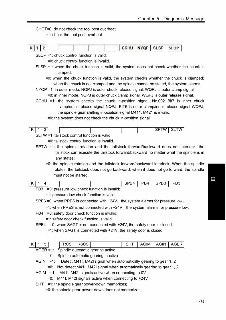
8/17/2019 980TDc CNC Turning Controller User Manual
http://slidepdf.com/reader/full/980tdc-cnc-turning-controller-user-manual 454/461
Chapter 5 Diagnosis Message
439
C onn e c t i on
CHOT=0: do not check the tool post overheat
=1: check the tool post overheat
SLQP =1: chuck control function is valid;=0: chuck control function is invalid.
SLSP =1: when the chuck function is valid, the system does not check whether the chuck is
clamped;
=0: when the chuck function is valid, the system checks whether the chuck is clamped;
when the chuck is not clamped and the spindle cannot be stated, the system alarms.
NYQP =1: in outer mode, NQPJ is outer chuck release signal, WQPJ is outer clamp signal;
=0: in inner mode, NQPJ is outer chuck clamp signal, WQPJ is outer release signal.
CCHU =1: the system checks the chuck in-position signal, No.002 Bit7 is inner chuck
clamp/outer release signal NQPJ, BIT6 is outer clamp/inner release signal WQPJ,
the spindle gear shifting in-position signal M411, M421 is invalid.=0: the system does not check the chuck in-position signal.
K 1 3 SPTW SLTW
SLTW =1: tailstock control function is valid;
=0: tailstock control function is invalid.
SPTW =1: the spindle rotation and the tailstock forward/backward does not interlock, the
tailstock can execute the tailstock forward/backward no matter what the spindle is in
any states;
=0: the spindle rotation and the tailstock forward/backward interlock. When the spindle
rotates, the tailstock does not go backward; when it does not go forward, the spindle
must not be started.
K 1 4 SPB4 PB4 SPB3 PB3
PB3 =0: pressure low check function is invalid;
=1: pressure low check function is valid.
SPB3 =0: when PRES is connected with +24V,the system alarms for pressure low;
=1: when PRES is not connected with +24V,the system alarms for pressure low.
PB4 =0: safety door check function is invalid;
=1: safety door check function is valid.
SPB4 =0: when SAGT is not connected with +24V, the safety door is closed;=1: when SAGT is connected with +24V, the safety door is closed.
K 1 5 RCS RSCS SHT AGIM AGIN AGER
AGER =1: Spindle automatic gearing active
=0: Spindle automatic gearing inactive
AGIN =1: Detect M41I, M42I signal when automatically gearing to gear 1, 2
=0: Not detect M41I, M42I signal when automatically gearing to gear 1, 2
AGIM =1: M41I, M42I signals active when connecting to 0V
=0: M41I, M42I signals active when connecting to +24VSHT =1: the spindle gear power-down memorizes;
=0: the spindle gear power-down does not memorize.

8/17/2019 980TDc CNC Turning Controller User Manual
http://slidepdf.com/reader/full/980tdc-cnc-turning-controller-user-manual 455/461
GSK980TDc Turning CNC System User Manual
440
C onn e c t i on
RSCS =1: close the spindle contour control in emergent stop, reset;
=0: does not close the spindle contour control in emergent stop, reset
RCS =1: Cs function is valid;
=0: Cs function is invalid.
K 1 6 SINC M32A ROVI SOVI
SINC 1: in Step(MPG) mode, ×1000 is invalid, ×1, ×10, ×100 are valid;
0: in Step(MPG) mode, ×1, ×10, ×100, ×1000 are valid.
SOVI =1: external feedrate override switch is valid;
=0: external feedrate override switch is invalid.
ROVI =1: external feedrate override is reverse;
=0: external feedrate override is not reverse.
M32A =1: output the lubricating in starting the system when the automatic lubricating is valid;
=0: do not output the lubricating in starting the system when the automatic lubricating is
valid.
K 1 7 MSEN SCLP SALM2 SALM SSTP *** *** ***
SSTP =0: do not close the analog voltage when the spindle stops;
=1: close the analog voltage when the spindle stops.
SALM =0: the alarm occurs when the spindle HIGH;
=1: the alarm occurs when the spindle HIGH.
SALM2=0: the occurs when the 2nd spindle HIGH;
=1: the occurs when the 2nd spindle LOW.
SCLP =0: the spindle clamping commands executes the 1st spindle clamped, the multi-spindle
function is valid;=1: the spindle clamping commands executes the 2nd spindle clamped, the multi-spindle
function is valid;
MSEN =0: the multi-spindle control function is invalid;
=1: the multi-spindle control function is invalid.
K 1 8 *** *** *** *** MDOK MD4 MD2 MD1
MDOK =0: the operation mode when power-on again is the one that the system is turned off;
=1: the operation mode when power-on is the one specified by MD4, MD2, MD1.
MD4 MD2 MD1 Operation mode when power on
0 0 0 MDI mode0 0 1 Auto mode
0 1 0 Program zero return
0 1 1 Edit mode
1 0 0 MPG mode
1 0 1 Manual mode
1 1 0 Machine zero return
5.3 PLC Data
5.3.1 Timer address T(defined by standard PLC ladders)
Address Meaning

8/17/2019 980TDc CNC Turning Controller User Manual
http://slidepdf.com/reader/full/980tdc-cnc-turning-controller-user-manual 456/461
Chapter 5 Diagnosis Message
441
C onn e c t i on
T0000 Timing the closing previous gear count
T0001 Timing from New gear outputting to FIN
T0002 M3, 4, 5, 8, 9, 10, 11, 32, 33 execution timing
T0004 timing from tool CCW stop to CW start
T0005 timing for tool CW
T0006 S code execution timing
T0007 M01, 02, 30 execution timing
T0008 Having not received alarm time of TCP signal
T0009 Tool rotation(CW) timing
T0010 Timing from the spindle stop to brake output
T0011 Spindle brake output timing
T0012 Spindle jog timing
T0013 timing the lubricating jog output time
T0018 Chuck pulse output timing
T0021 Spindle stop, check operation enabling delayT0039 M01,02,30 execution timing
T0046 Spindle speed/position switch timing
5.3.2 Counter address C(Defined by standard PLC Ladders)
Address Meaning
C0001 Rapid feedrate override - counting on MDI panel
C0002 Rapid feedrate override + counting on MDI panel
C0004 Feed - counting on MDI panel
C0005 Feed + counting on MDI panelC0006 Spindle override – counting on MDI panel
C0007 Spindle override + counting on MDI panel
C0016 Manual feed – counting on MDI panel
C0017 Manual feed + counting on MDI panel
C0020 2 resetting counting of tool change unfinished alarm
5.3.3 Timer presetting address DT(Defined by standard PLC ladders)
Address Meaning
DT000 Time for original gear disabling during spindle automaticgear changing (ms)
DT001 Delay time after the changed spindle gear is in position (ms)
DT002 Detection time for low pressure alarm (ms)
DT004 Permit time for tool changing (ms)
DT005 M command execution time (ms)
DT006 S command execution time (ms)
DT007 Delay time for tool post from CW to CCW output (ms)
DT008 Tool post lock signal detection time (ms)
DT009 Tool post CCW rotation lock time (ms)DT010 Spindle braking delay output time (ms)
DT011 Spindle braking output time (ms)
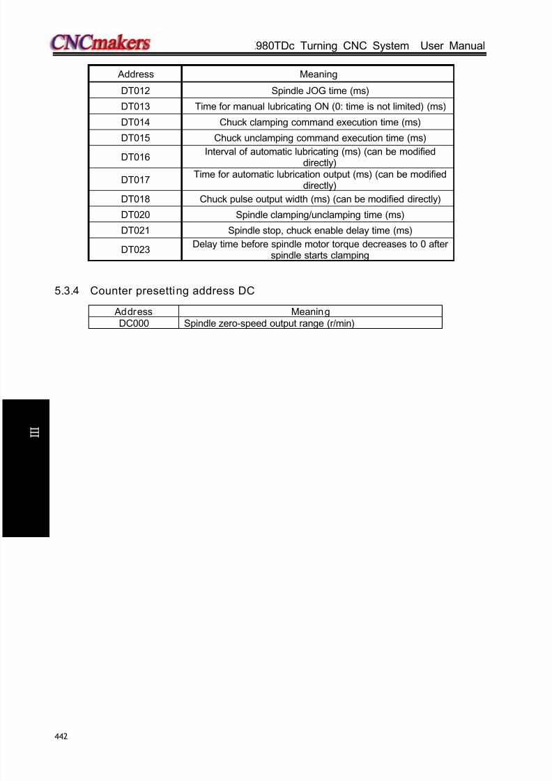
8/17/2019 980TDc CNC Turning Controller User Manual
http://slidepdf.com/reader/full/980tdc-cnc-turning-controller-user-manual 457/461
GSK980TDc Turning CNC System User Manual
442
C onn e c t i on
Address Meaning
DT012 Spindle JOG time (ms)
DT013 Time for manual lubricating ON (0: time is not limited) (ms)
DT014 Chuck clamping command execution time (ms)
DT015 Chuck unclamping command execution time (ms)
DT016Interval of automatic lubricating (ms) (can be modified
directly)
DT017Time for automatic lubrication output (ms) (can be modified
directly)
DT018 Chuck pulse output width (ms) (can be modified directly)
DT020 Spindle clamping/unclamping time (ms)
DT021 Spindle stop, chuck enable delay time (ms)
DT023Delay time before spindle motor torque decreases to 0 after
spindle starts clamping
5.3.4 Counter presetting address DC
Address Meaning
DC000 Spindle zero-speed output range (r/min)
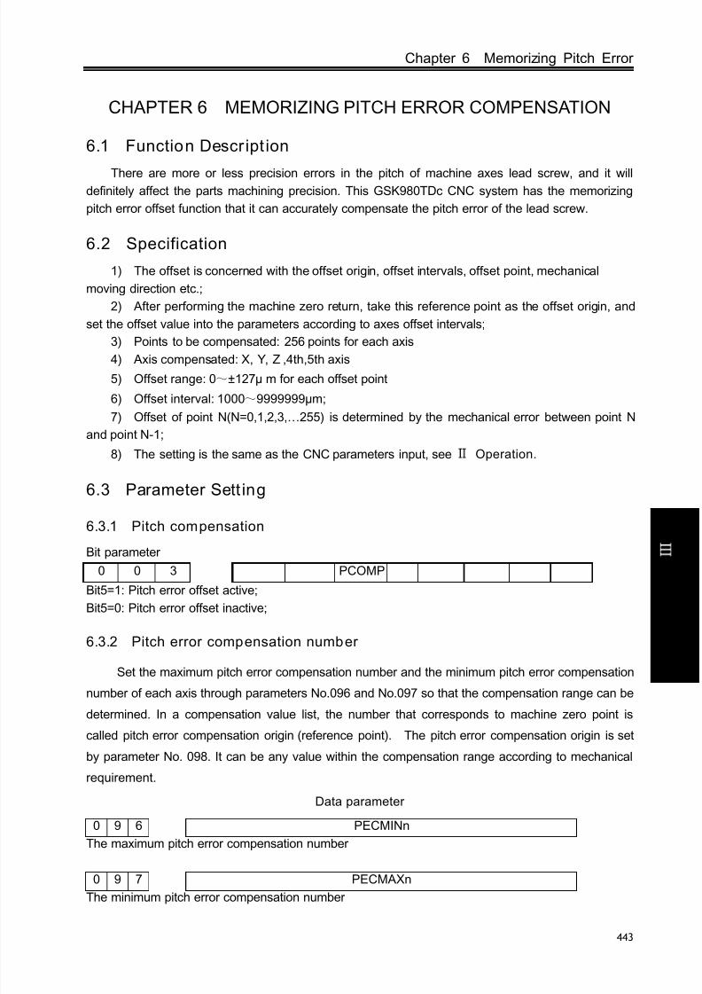
8/17/2019 980TDc CNC Turning Controller User Manual
http://slidepdf.com/reader/full/980tdc-cnc-turning-controller-user-manual 458/461
Chapter 6 Memorizing Pitch Error
443
C onn e c t i on
CHAPTER 6 MEMORIZING PITCH ERROR COMPENSATION
6.1 Function Descript ion
There are more or less precision errors in the pitch of machine axes lead screw, and it willdefinitely affect the parts machining precision. This GSK980TDc CNC system has the memorizing
pitch error offset function that it can accurately compensate the pitch error of the lead screw.
6.2 Specification
1) The offset is concerned with the offset origin, offset intervals, offset point, mechanical
moving direction etc.;
2) After performing the machine zero return, take this reference point as the offset origin, and
set the offset value into the parameters according to axes offset intervals;
3) Points to be compensated: 256 points for each axis4) Axis compensated: X, Y, Z ,4th,5th axis
5) Offset range: 0~±127µ m for each offset point
6) Offset interval: 1000~9999999µm;
7) Offset of point N(N=0,1,2,3,…255) is determined by the mechanical error between point N
and point N-1;
8) The setting is the same as the CNC parameters input, see Operation.
6.3 Parameter Sett ing
6.3.1 Pitch compensation
Bit parameter
0 0 3 PCOMP
Bit5=1: Pitch error offset active;
Bit5=0: Pitch error offset inactive;
6.3.2 Pitch error compensation number
Set the maximum pitch error compensation number and the minimum pitch error compensation
number of each axis through parameters No.096 and No.097 so that the compensation range can bedetermined. In a compensation value list, the number that corresponds to machine zero point is
called pitch error compensation origin (reference point). The pitch error compensation origin is set
by parameter No. 098. It can be any value within the compensation range according to mechanical
requirement.
Data parameter
0 9 6 PECMINn
The maximum pitch error compensation number
0 9 7 PECMAXn
The minimum pitch error compensation number

8/17/2019 980TDc CNC Turning Controller User Manual
http://slidepdf.com/reader/full/980tdc-cnc-turning-controller-user-manual 459/461
GSK980TDc Turning CNC System User Manual
444
C onn e c t i on
0 9 8 PECORGn
The pitch error compensation number that corresponds to machine zero point
6.3.3 Pitch error compensation interval
0 9 9 PECINTn
[Meaning] Interval between pitch error compensation point
[Unit]
Setting Unit IS-B IS-C
Metric machine 0.001 mm 0.0001 mm
Inch machine 0.0001 inch 0.00001 inch
[Range]
IS-B IS-C
Metric machine 1000~
999999 10000~
9999999Inch machine 400~999999 4000~9999999
6.3.4 Offset value
The axes pitch offset values are set according to the parameter No. in the following table. The
offset value is input by diameter with the input unit 0.001mm, which is irrelevant to diameter or radius
programming.
Offset No. X Z Y
000 … … …
001 5 -2 3
002 -3 4 -1
… … … …
255 … … …
6.4 Notes of Offset Setting
①The setting and alteration of pitch offset can only be done at the authority of password level 2.
② After the parameter of pitch offset is set, only the machine zero is returned could the offset be
done.
6.5 Sett ing Examples of Offset Parameters
①Data parameter No.099(pitch error origin) =0, Data parameter No.103 (offset interval)=10.000
When the pitch error origin is set to 0:
Assume that the pitch error compensation range is 0~255.
①Data parameter No.098 (pitch error origin) =0, Data parameter No.099 (offset interval)=10.000
When the pitch error origin is set to 0:
The offset value for the 1st segment is set by the position No.001 in the offset table, the offset
value for the 2nd segment is set by the position No.002 in the offset table, and the offset value for the
Nth segment is set by the position No.000+N in the offset table.
The machine zero is regarded as the reference point of pitch error origin, it begins to compensate

8/17/2019 980TDc CNC Turning Controller User Manual
http://slidepdf.com/reader/full/980tdc-cnc-turning-controller-user-manual 460/461
Chapter 6 Memorizing Pitch Error
445
C onn e c t i on
the position No.001 in the offset table from the machine zero. So the pitch error offset can only be
done in the positive moving direction of the machine coordinate system.
The position No.000 in the offset table corresponds to the reference point (i.e. pitch error origin
0), the offset point 1 corresponds to a point of positive 10.000 moving from this reference point, and a
following offset point from this point every 10.000 interval. The 127th offset point is the offset at
position 1270.000. Therefore, at offset point 1, set a offset value moving from 0 to 10.000, at offset
point 2, set a offset value when moving from 10.000 to 20.000. At offset point N, set a offset valuewhen moving from (N-1)×(offset interval) to N×(offset interval).
The following table content is resulted from the above:
Actually the machine moves from the reference point to the point of +30.000, the pitch error offset
is: (+7)+(-6)+(+4)=+5
②Data parameter No.099 (pitch error origin) =60, No.103(offset interval) =10.000
When the pitch error origin is set to 60:
For the positive moving, the 1st segment error offset is set by position No.061 in the offset table,
the 2nd segment by position No.062. The Nth segment error offset is set by position No.060+N in the
offset table.
For the negative moving, the 1st segment error offset is set by position No.060 in the offset table,
the 2
nd
segment by position No.059. The Nth segment error offset is set by position No.060-N in theoffset table.
The machine zero is taken as the reference point of the pitch error origin, when moving from the
positive of machine coordinate system, it begins to compensate by the corresponding position
No.061 in the offset table; when moving from the negative of the machine coordinate system, it
begins to compensate by the position No.060. Therefore the pitch offset can be done when moving in
the positive or the negative axis of machine coordinate system.
Machine coordinate
system
Offset
parameter No.
Offset
value
Drive unit current code
pulses before compensating
Drive unit current command
pulses after compensating
Reference point 0 000 000 00000 00000
10.000 001 7 10000 10007
20.000 002 -6 20000 20001
30.000 003 4 30000 30005
…… 004 …

8/17/2019 980TDc CNC Turning Controller User Manual
http://slidepdf.com/reader/full/980tdc-cnc-turning-controller-user-manual 461/461
GSK980TDc Turning CNC System User Manual
Setting
point
Machine
coordinate
system
(Reference point)0 +10.000-20.000-60.000
58 59 60 61
(-7) (-7) (+6) (+4)
127
+670.000
(+1)(+0)
-10.000
The position No.060 in the offset table corresponds to the reference point (60), position No.061
to a point of positive10.000 move from origin. So there is a offset point every 10.000 from position 61,
the 127th offset point corresponds to the offset of position +670.000. While the position No.059
corresponds to a point of negative 10.000 move from reference point. Also there is a offset point
every 10.000 from position 59, the offset point 0 corresponds to the offset at position -600.000.
Therefore the point N is set by a offset of move from (N-61)×(offset interval) to (N-60)×(offset
interval).
The following table content is resulted from the above:
Machine
coordinate
system
Offset parameter
No.Offset value
Drive unit current
code pulses before
compensating
Drive unit current
code pulses after
compensating
-30.000 058 -7 -30000 -29992
-20.000 059 -7 -20000 -19999
-10.000 060 +6 -10000 -10006
Reference
point 0 0 0
10.000 061 +4 10000 10004
…… 062 …
Related Documents