SBC - 2408 / 2410 / 2413 3 Stage Battery Charger User Manual Keep this manual in a safe place for quick reference at all times. This manual contains important safety and operation instructions for correct use of the battery charger. Read through the manua l and pay special attenti on to the markings and labels of the char ger, battery and equ ipment connected to th e battery syst em. Pay special attention to these two types of notices used in this manual. WARNING : Failure to heed this warning may cause injury to persons and damage to Equipment. CAUTION : Failure to observe this warning may result in damage to equipment and improper functioning of the Charger. WARNING : ● The charger is designed for in-door use. Protect the charger from ingress of water. ● This charger is made to charge only properly sized lead acid batteries. ● Don't recharging non-rechargeable batteries. ● Charging other types of battery or under-sized lead acid batteries may cause fire or explosion. ● Install the charger in accordance with all local codes ● Do not use the charger if it has been dropped or damaged. ● Do not remove casing of the charger, there is no user –serviceable parts inside. ● Do not charge the battery on boats. Remove the battery and charge on shore. ● Never attem pt to charge a frozen batte ry ● Never attem pt to charge a dama ged battery. ● Wear protective goggles and turn your face away when connecting or disconnecting the battery. ● Never place the c harger on top of a batter y . ● Never smoke, use an open flame, or create sparks near b attery or charger during normal charging operation as batteries may give out explosive gas. ● Do not charge batteries in an enclosu re (box- in) due to possible explosion of entrapped explosive gas. ● Use of accessory not recommended may cause risk of fire, electric shock. ● Disconnect the mains supply before connecting or disconnecting the links to the battery. ● If the charger does not work properly or if it has been damaged ,unplug its AC and DC connection. CAUTIONS : ● Refer to battery manufacturer’s specific recommended values for battery type settings and float voltage setting. ● Fix the charger to a horizontal solid support via four grooves at the flange of chassis, with four screws or nuts. ● Ensure all ventilation ports are not obstructed for efficient fan cooling, keep loose soft material or paper off at the bottom of the charger. ● During charging, the battery must be placed in a well ventilated area. ● If longer output charging cord is required, make sure the diameter is adequate for the current in given cable length.

Welcome message from author
This document is posted to help you gain knowledge. Please leave a comment to let me know what you think about it! Share it to your friends and learn new things together.
Transcript

7/30/2019 96669599 Solar Mobile Charger
http://slidepdf.com/reader/full/96669599-solar-mobile-charger 1/8
SBC - 2408 / 2410 / 2413
3 Stage Battery Charger
User Manual
Keep this manual in a safe place for quick reference at all times.
This manual contains important safety and operation instructions for correct use of the battery charger. Read through the manual and pay special attention to the markings and labels of the charger, battery and equipment connected to the battery system.
Pay special attention to these two types of notices used in this manual.
WARNING :Failure to heed this warning may cause injury to persons and damage to Equipment.
CAUTION :
Failure to observe this warning may result in damage to equipment and improper functioning of the Charger.
WARNING :
● The charger is designed for in-door use. Protect the charger from ingress of water.● This charger is made to charge only properly sized lead acid batteries.● Don't recharging non-rechargeable batteries.● Charging other types of battery or under-sized lead acid batteries may cause fire or explosion.● Install the charger in accordance with all local codes● Do not use the charger if it has been dropped or damaged.● Do not remove casing of the charger, there is no user –serviceable parts inside.● Do not charge the battery on boats. Remove the battery and charge on shore.● Never attempt to charge a frozen battery●
Never attempt to charge a damaged battery.● Wear protective goggles and turn your face away when connecting or disconnecting the battery.● Never place the charger on top of a battery .● Never smoke, use an open flame, or create sparks near battery or charger during normal charging operation as batteries may give
out explosive gas.● Do not charge batteries in an enclosure (box- in) due to possible explosion of entrapped explosive gas.● Use of accessory not recommended may cause risk of fire, electric shock.● Disconnect the mains supply before connecting or disconnecting the links to the battery.● If the charger does not work properly or if it has been damaged ,unplug its AC and DC connection.
CAUTIONS :
● Refer to battery manufacturer’s specific recommended values for battery type settings and float voltage setting.●
Fix the charger to a horizontal solid support via four grooves at the flange of chassis, with four screws or nuts.● Ensure all ventilation ports are not obstructed for efficient fan cooling, keep loose soft material or paper off at the bottom of the
charger.● During charging, the battery must be placed in a well ventilated area.● If longer output charging cord is required, make sure the diameter is adequate for the current in given cable length.
7/30/2019 96669599 Solar Mobile Charger
http://slidepdf.com/reader/full/96669599-solar-mobile-charger 2/8
Introduction
Congratulations on purchasing our new 3-Stage (IU0U) Switching Mode Battery Charger.This battery charger is suitable for wet, sealed (RVLA), calcium-calcium, GEL and AGM in both car (SLI) and deep cycle type of lead acid battery.It is a “set and forget” automatic charger which can be permanently connected to battery.These models have dual charge banks for charging two batteries simultaneously.The special selectable Power Supply Mode allows charging battery with external load.
Intended Use:
All Automotive, Marine, Mobile Home, Electric Scooters, Golf Carts, Solar, Deep Cycle, UPS Standby, Industrial & CommercialApplications.
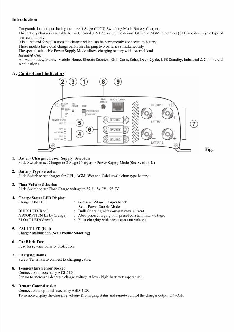
A. Control and Indicators
1. Battery Charger / Power Supply SelectionSlide Switch to set Charger to 3-Stage Charger or Power Supply Mode (See Section G)
2. Battery Type Selection
Slide Switch to set charger for GEL, AGM, Wet and Calcium-Calcium type battery.
3. Float Voltage SelectionSlide Switch to set Float Charge voltage to 52.8 / 54.0V / 55.2V.
4. Charge Status LED DisplayCharger ON LED : Green – 3-Stage Charger Mode
Red - Power Supply ModeBULK LED (Red ) : Bulk Charging with constant max. currentABSORPTION LED (Orange) : Absorption charging with preset constant max. voltage.FLOAT LED (Green) : Float charging with preset constant voltage
5. FAULT LED (Red)
Charger malfunction (See Trouble Shooting)
6. Car Blade FuseFuse for reverse polarity protection .
7. Charging BanksScrew Terminals to connect to charging cable.
8. Temperature Sensor SocketConnection to accessory ATS-5120Sensor to increase / decrease charge voltage at low / high battery temperature .
9. Remote Control socket
Connection to optional accessory ABD-4120.To remote display the charging voltage & charging status and remote control the charger output ON/OFF.
Fig.1
7/30/2019 96669599 Solar Mobile Charger
http://slidepdf.com/reader/full/96669599-solar-mobile-charger 3/8
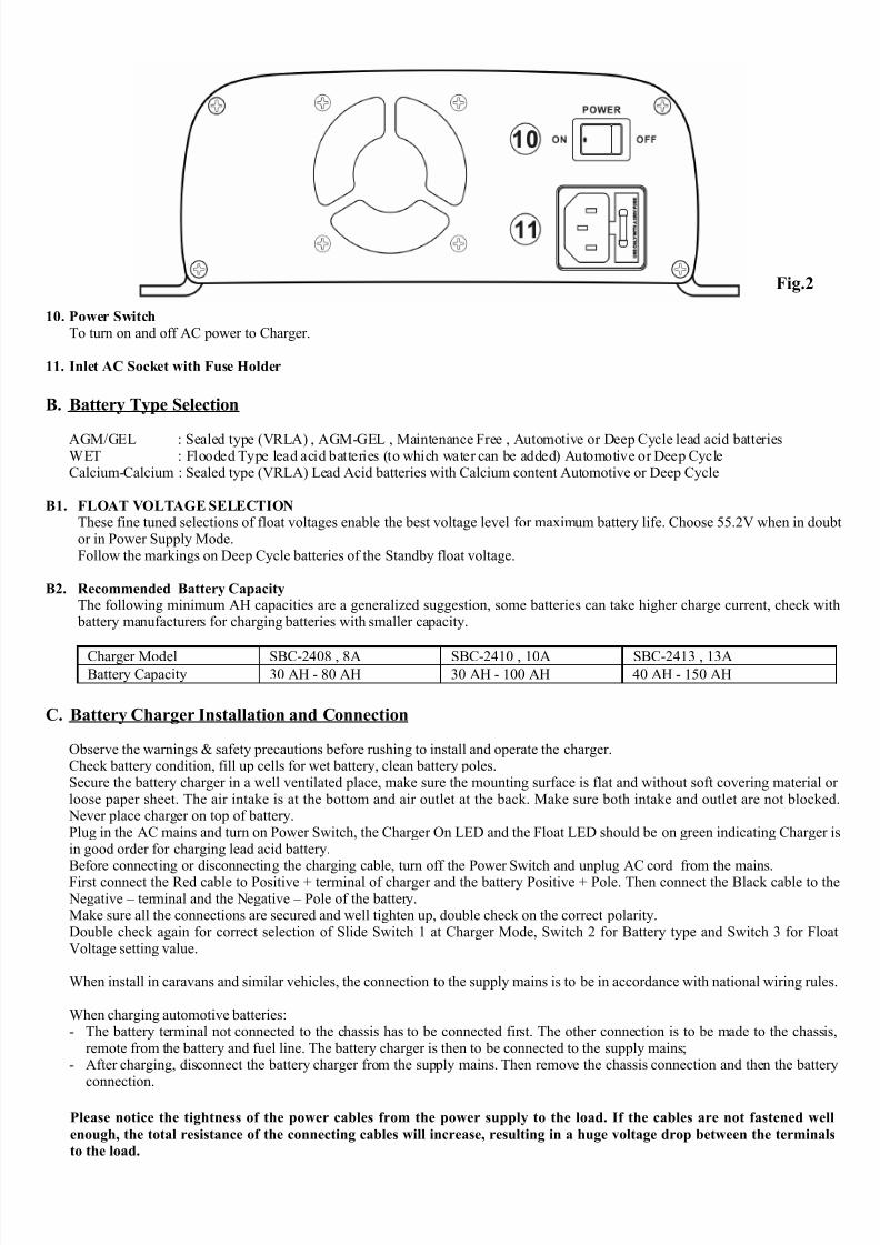
10. Power Switch
To turn on and off AC power to Charger.
11. Inlet AC Socket with Fuse Holder
B. Battery Type Selection
AGM/GEL : Sealed type (VRLA) , AGM-GEL , Maintenance Free , Automotive or Deep Cycle lead acid batteriesWET : Flooded Type lead acid batteries (to which water can be added) Automotive or Deep CycleCalcium-Calcium : Sealed type (VRLA) Lead Acid batteries with Calcium content Automotive or Deep Cycle
B1. FLOAT VOLTAGE SELECTIONThese fine tuned selections of float voltages enable the best voltage level for maximum battery life. Choose 55.2V when in doubtor in Power Supply Mode.Follow the markings on Deep Cycle batteries of the Standby float voltage.
B2. Recommended Battery CapacityThe following minimum AH capacities are a generalized suggestion, some batteries can take higher charge current, check with battery manufacturers for charging batteries with smaller capacity.
Charger Model SBC-2408 , 8A SBC-2410 , 10A SBC-2413 , 13ABattery Capacity 30 AH - 80 AH 30 AH - 100 AH 40 AH - 150 AH
C. Battery Charger Installation and Connection
Observe the warnings & safety precautions before rushing to install and operate the charger.Check battery condition, fill up cells for wet battery, clean battery poles.Secure the battery charger in a well ventilated place, make sure the mounting surface is flat and without soft covering material or loose paper sheet. The air intake is at the bottom and air outlet at the back. Make sure both intake and outlet are not blocked. Never place charger on top of battery.Plug in the AC mains and turn on Power Switch, the Charger On LED and the Float LED should be on green indicating Charger isin good order for charging lead acid battery.
Before connecting or disconnecting the charging cable, turn off the Power Switch and unplug AC cord from the mains.First connect the Red cable to Positive + terminal of charger and the battery Positive + Pole. Then connect the Black cable to the Negative – terminal and the Negative – Pole of the battery.Make sure all the connections are secured and well tighten up, double check on the correct polarity.Double check again for correct selection of Slide Switch 1 at Charger Mode, Switch 2 for Battery type and Switch 3 for FloatVoltage setting value.
When install in caravans and similar vehicles, the connection to the supply mains is to be in accordance with national wiring rules.
When charging automotive batteries:- The battery terminal not connected to the chassis has to be connected first. The other connection is to be made to the chassis,
remote from the battery and fuel line. The battery charger is then to be connected to the supply mains;- After charging, disconnect the battery charger from the supply mains. Then remove the chassis connection and then the battery
connection.
Please notice the tightness of the power cables from the power supply to the load. If the cables are not fastened well
enough, the total resistance of the connecting cables will increase, resulting in a huge voltage drop between the terminals
to the load.
Fig.2
7/30/2019 96669599 Solar Mobile Charger
http://slidepdf.com/reader/full/96669599-solar-mobile-charger 4/8
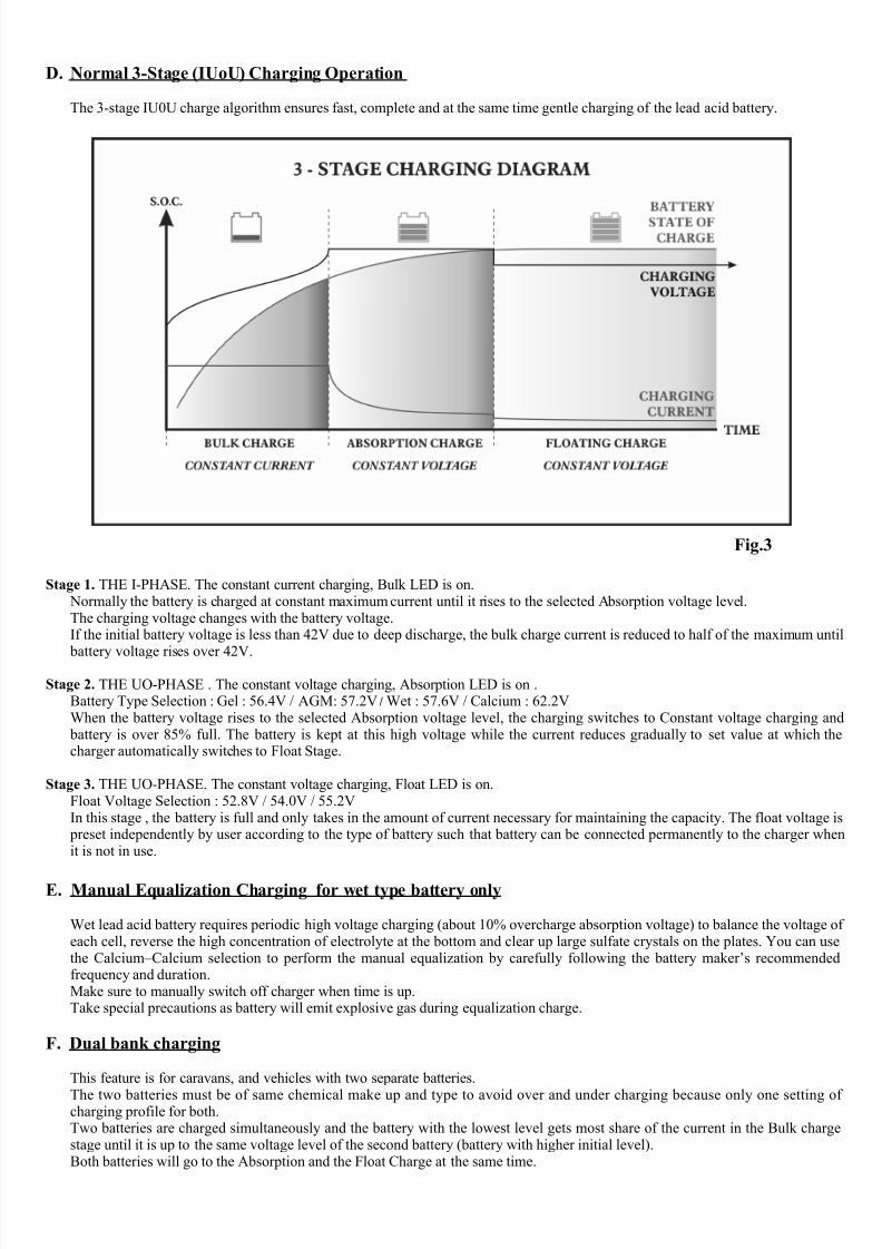
D. Normal 3-Stage (IUoU) Charging Operation
The 3-stage IU0U charge algorithm ensures fast, complete and at the same time gentle charging of the lead acid battery.
Stage 1. THE I-PHASE. The constant current charging, Bulk LED is on. Normally the battery is charged at constant maximum current until it rises to the selected Absorption voltage level.The charging voltage changes with the battery voltage.If the initial battery voltage is less than 42V due to deep discharge, the bulk charge current is reduced to half of the maximum until
battery voltage rises over 42V.
Stage 2. THE UO-PHASE . The constant voltage charging, Absorption LED is on .Battery Type Selection : Gel : 56.4V / AGM: 57.2V / Wet : 57.6V / Calcium : 62.2VWhen the battery voltage rises to the selected Absorption voltage level, the charging switches to Constant voltage charging and battery is over 85% full. The battery is kept at this high voltage while the current reduces gradually to set value at which thecharger automatically switches to Float Stage.
Stage 3. THE UO-PHASE. The constant voltage charging, Float LED is on.Float Voltage Selection : 52.8V / 54.0V / 55.2VIn this stage , the battery is full and only takes in the amount of current necessary for maintaining the capacity. The float voltage is preset independently by user according to the type of battery such that battery can be connected permanently to the charger whenit is not in use.
E. Manual Equalization Charging for wet type battery only
Wet lead acid battery requires periodic high voltage charging (about 10% overcharge absorption voltage) to balance the voltage of each cell, reverse the high concentration of electrolyte at the bottom and clear up large sulfate crystals on the plates. You can usethe Calcium–Calcium selection to perform the manual equalization by carefully following the battery maker’s recommendedfrequency and duration.Make sure to manually switch off charger when time is up.Take special precautions as battery will emit explosive gas during equalization charge.
F. Dual bank charging
This feature is for caravans, and vehicles with two separate batteries.
The two batteries must be of same chemical make up and type to avoid over and under charging because only one setting of charging profile for both.Two batteries are charged simultaneously and the battery with the lowest level gets most share of the current in the Bulk chargestage until it is up to the same voltage level of the second battery (battery with higher initial level).Both batteries will go to the Absorption and the Float Charge at the same time.
Fig.3

7/30/2019 96669599 Solar Mobile Charger
http://slidepdf.com/reader/full/96669599-solar-mobile-charger 5/8
G. Power Supply / 2-Stage Charger Mode (see Fig.4)
At this mode the Charger On (4) LED becomes red color and only Bulk and Float LED will function. The bulk LED will be off when battery is charged to about 80% full.The 3-stage charger becomes a 2-stage charger or as power supply in this selected mode because 3-stage charger overcharges battery with external load.This selected mode is intended for use to charge battery with external load such as caravan or other battery and external loadcombination.A 2-Stage charger can be used as a combination charger/power supply. An external load can draw current from the charger whilethe charger is recharging a battery. The charger does not care how much current is being diverted by an external circuit as itswitches from Bulk mode (constant current ) to Float mode based only on the battery terminal voltage.However, a 2-Stage charger cannot completely charge the battery when the charger switches from bulk mode to float mode. After switching to float mode, the battery will, in most cases, be about 80% recharged. The battery receives the remaining rechargewhile in float mode over several days.It is highly recommended to switch back to the 3-Stage Charger Mode periodically when the external load is disconnected.Also the external load should not be more than 50% of the max. current of the charger , unless the battery is fully charged up . If the bulk LED is on most of the time then the load is too large.
G1. As a stand alone power supplyIt can also be used as a stand alone power supply without connection to a batteryIt will provide a constant voltage according to the selected Float Voltage (52.8/54.0/55.2V) and rated DC current of the charger.However, it is not recommended for high surge load (such as lamp) in stand alone application as the initial high surge current
will trigger the overload protection of the power supply.
Fig.4 Power Supply / 2-Stage Charger Mode Application
7/30/2019 96669599 Solar Mobile Charger
http://slidepdf.com/reader/full/96669599-solar-mobile-charger 6/8
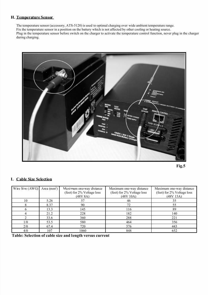
H. Temperature Sensor
The temperature sensor (accessory, ATS-5120) is used to optimal charging over wide ambient temperature range.Fix the temperature sensor in a position on the battery which is not affected by other cooling or heating source.Plug in the temperature sensor before switch on the charger to activate the temperature control function, never plug in the charger during charging.
I. Cable Size Selection
Wire Size (AWG) Area (mm2) Maximum one-way distance(feet) for 2% Voltage loss
(48V 8A)
Maximum one-way distance(feet) for 2% Voltage loss
(48V 10A)
Maximum one-way distance(feet) for 2% Voltage loss
(48V 13A)
10 5.26 57 46 35
8 8.37 90 72 556 13.3 145 116 89
4 21.2 228 182 140
2 33.6 360 288 221
1/0 53.5 580 464 356
2/0 67.4 720 576 443
4/0 107 1060 848 652
Table: Selection of cable size and length versus current
Fig.5

7/30/2019 96669599 Solar Mobile Charger
http://slidepdf.com/reader/full/96669599-solar-mobile-charger 7/8
J. Trouble Shooting
PROBLEM INDICATIONS POSSIBLE CAUSES SUGGESTED SOLUTION
Charger does notwork
Indicator lights notturn on
No AC power
AC input socket fuse blown
Check AC connections are correct
Replace with correct AC fuse by qualifiedelectrician
No DC output Charger - On LED isnot on, Float andFault LEDs are on.
Output short circuit
Over temperature protection triggered
Severe over loading charger
Reverse polarity connection
Check DC connections between charger and battery
Check air intake vent at bottom of charger is blocked or not. Check charger ambientventilation .Check battery AH capacity withinrecommended rangeCheck for correct polarity, replace car blade fuse (6)
Battery does not getfull charge
All indicator LEDwork normally andsequentially
Bad battery connection
Battery type select switch in wrong setting
Battery capacity too large
Ambient temperature too low
Battery has damaged cell or battery is tooold
Check for loose contact, right cable size,cable integrityRecheck battery type and change to
correct battery selectionMake sure charger rating matches batterycapacity see table (B2)Move battery to a room temperaturelocation, or get an optional temperaturesensor Replace battery
Long chargingtime , float lightdoes not come oneven after 20 hours
charging time.
Absorption lightremains on all thetime
Wrong battery type selection eg. chargegel battery with Calcium-Calcium OR Wettype selection
Total battery capacity is too high for dualcharging
Battery temperature too high
Battery is defective
A load is connected to battery and charger is not in power supply mode.
Check charged battery label and change battery type selection to correct setting.
Check battery capacity or charge batteryseparately
Use temperature sensor (optionalaccessory)
Replace battery
Change charger Selector Switch (1) toPower Supply Mode.
Bulk LED is on allthe time
Bulk light remainson all the time whenCharger is in Power
Supply Mode,charger ON LED (4)is on red.
The connected load is too large, usingmost of the current from the charger.
Reduce the load to about 50% of thecharger's rating current Or take away theload and set Charger to Battery Charger
Mode to fully charge the battery beforereturn back to the power supply settingand load connection.
Bulk light remainson all the time whenCharger is in BatteryCharger ON LED(4) is on green.
Wrong battery type selection
Battery is excessively depleted and thesoft charging is triggered
Battery temperature too high
Check charged battery label and change battery type selection to correct setting.Recharge the battery after a day, if bulk light remains after several hours, the battery is most likely damaged and cannotaccept charge. Replace battery.Use accessory temperature sensor
7/30/2019 96669599 Solar Mobile Charger
http://slidepdf.com/reader/full/96669599-solar-mobile-charger 8/8
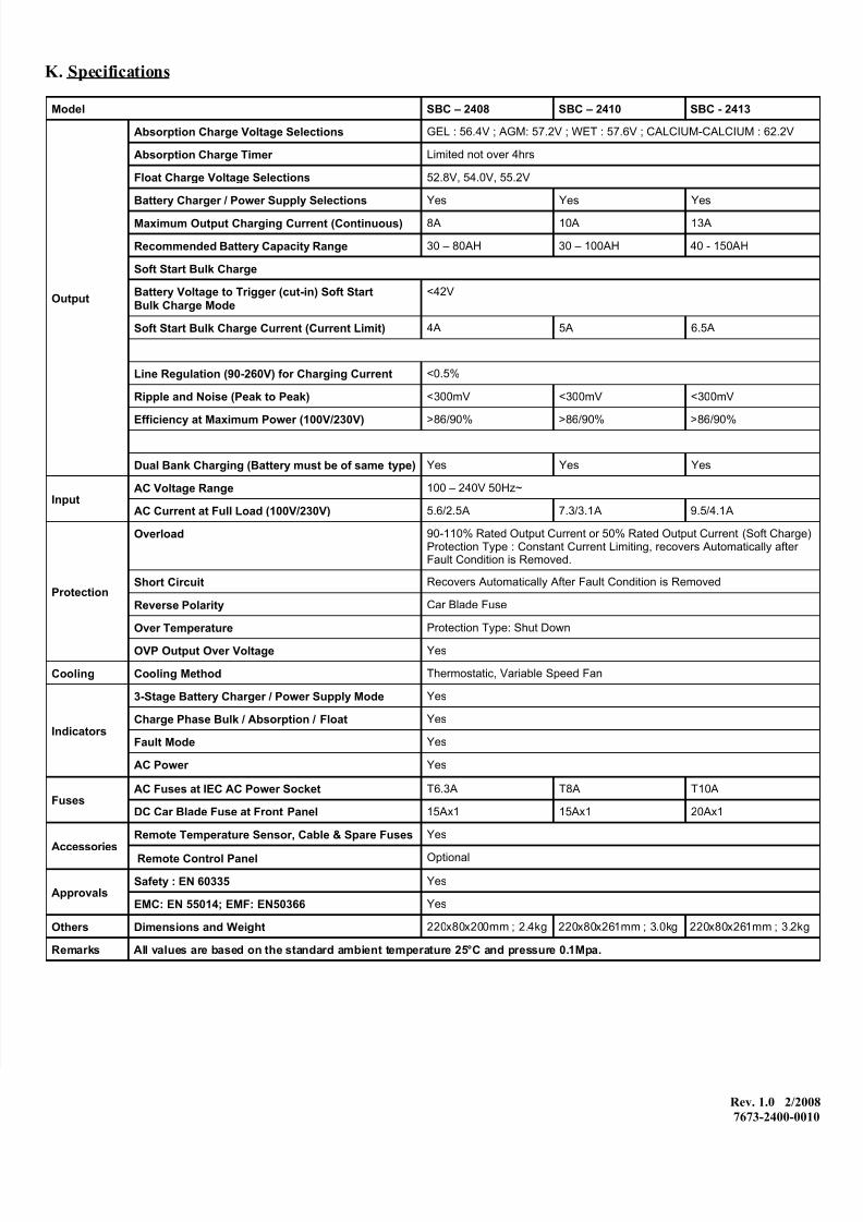
K. Specifications
Model SBC – 2408 SBC – 2410 SBC - 2413
Output
Absorption Charge Voltage Selections GEL : 56.4V ; AGM: 57.2V ; WET : 57.6V ; CALCIUM-CALCIUM : 62.2V
Absorption Charge Timer Limited not over 4hrs
Float Charge Voltage Selections 52.8V, 54.0V, 55.2V
Battery Charger / Power Supply Selections Yes Yes Yes
Maximum Output Charging Current (Continuous) 8A 10A 13A
Recommended Battery Capacity Range 30 – 80AH 30 – 100AH 40 - 150AH
Soft Start Bulk Charge
Battery Voltage to Trigger (cut-in) Soft StartBulk Charge Mode
<42V
Soft Start Bulk Charge Current (Current Limit) 4A 5A 6.5A
Line Regulation (90-260V) for Charging Current <0.5%
Ripple and Noise (Peak to Peak) <300mV <300mV <300mV
Efficiency at Maximum Power (100V/230V) >86/90% >86/90% >86/90%
Dual Bank Charging (Battery must be of same type) Yes Yes Yes
InputAC Voltage Range 100 – 240V 50Hz~
AC Current at Full Load (100V/230V) 5.6/2.5A 7.3/3.1A 9.5/4.1A
Protection
Overload 90-110% Rated Output Current or 50% Rated Output Current (Soft Charge)Protection Type : Constant Current Limiting, recovers Automatically after Fault Condition is Removed.
Short Circuit Recovers Automatically After Fault Condition is Removed
Reverse Polarity Car Blade Fuse
Over Temperature Protection Type: Shut Down
OVP Output Over Voltage Yes
Cooling Cooling Method Thermostatic, Variable Speed Fan
Indicators
3-Stage Battery Charger / Power Supply Mode Yes
Charge Phase Bulk / Absorption / Float Yes
Fault Mode Yes
AC Power Yes
FusesAC Fuses at IEC AC Power Socket T6.3A T8A T10A
DC Car Blade Fuse at Front Panel 15Ax1 15Ax1 20Ax1
AccessoriesRemote Temperature Sensor, Cable & Spare Fuses Yes
Remote Control Panel Optional
ApprovalsSafety : EN 60335 Yes
EMC: EN 55014; EMF: EN50366 Yes
Others Dimensions and Weight 220x80x200mm ; 2.4kg 220x80x261mm ; 3.0kg 220x80x261mm ; 3.2kg
Remarks All values are based on the standard ambient temperature 25°C and pressure 0.1Mpa.
Rev. 1.0 2/2008
7673-2400-0010
Related Documents