COOLING SYSTEM CONTENTS page page ACCESSORY DRIVE BELTS ................ 23 ENGINE BLOCK HEATER .................. 26 GENERAL INFORMATION .................. 1 SERVICE PROCEDURES .................. 10 SPECIFICATIONS ........................ 28 GENERAL INFORMATION COOLING SYSTEM Throughout this group, references may be made to a particular vehicle by letter or number designation. A chart showing the breakdown of these designations is included in the Introduction Section at the front of this service manual. The cooling system has a radiator, coolant, electric fan motor, shroud, pressure cap, thermostat, coolant reserve system, transmission oil cooler, a water pump to circulate the coolant, hoses, and clamps to com- plete the circuit. • When Engine is cold: Thermostat is closed, cooling system has no flow through the radiator. The coolant bypass flows through the engine only. • When Engine is warm: Thermostat is open, cooling system has bypass flow and coolant flow through ra- diator. Its primary purpose is to maintain engine temper- ature in a range that will provide satisfactory engine performance and emission levels under all expected driving conditions. It also provides hot water (cool- ant) for heater performance and cooling for automatic transmission oil. It does this by transferring heat Fig. 1 Cooling System Operation — 2.5L Engine . COOLING SYSTEM 7-1

Welcome message from author
This document is posted to help you gain knowledge. Please leave a comment to let me know what you think about it! Share it to your friends and learn new things together.
Transcript
COOLING SYSTEM
CONTENTS
page page
ACCESSORY DRIVE BELTS . . . . . . . . . . . . . . . . 23ENGINE BLOCK HEATER . . . . . . . . . . . . . . . . . . 26GENERAL INFORMATION . . . . . . . . . . . . . . . . . . 1
SERVICE PROCEDURES . . . . . . . . . . . . . . . . . . 10SPECIFICATIONS . . . . . . . . . . . . . . . . . . . . . . . . 28
GENERAL INFORMATION
COOLING SYSTEMThroughout this group, references may be made to
a particular vehicle by letter or number designation.A chart showing the breakdown of these designationsis included in the Introduction Section at the front ofthis service manual.
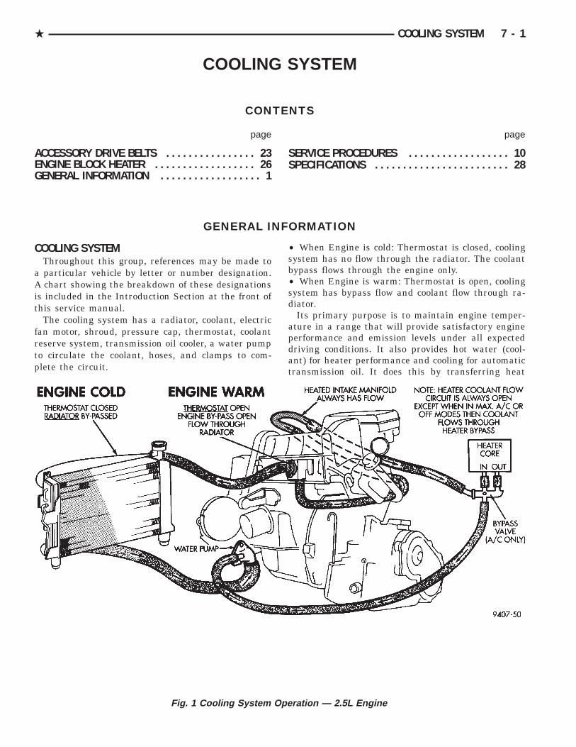
The cooling system has a radiator, coolant, electricfan motor, shroud, pressure cap, thermostat, coolantreserve system, transmission oil cooler, a water pumpto circulate the coolant, hoses, and clamps to com-plete the circuit.
• When Engine is cold: Thermostat is closed, coolingsystem has no flow through the radiator. The coolantbypass flows through the engine only.• When Engine is warm: Thermostat is open, coolingsystem has bypass flow and coolant flow through ra-diator.
Its primary purpose is to maintain engine temper-ature in a range that will provide satisfactory engineperformance and emission levels under all expecteddriving conditions. It also provides hot water (cool-ant) for heater performance and cooling for automatictransmission oil. It does this by transferring heat
Fig. 1 Cooling System Operation — 2.5L Engine
. COOLING SYSTEM 7 - 1

from engine metal to coolant, moving this heatedcoolant to the radiator, and then transferring thisheat to the ambient air.
Coolant flow circuits for 2.5L engine equipped vehi-cles is shown in Figure 1. Figure 2 shows 3.0L enginecoolant routing. Figure 4 shows 3.3/3.8L Engine Cool-ant routing.
Excluding heated intake manifold hose routing(hose is routed from waterbox directly to heater), allother system functions are essentially the same asshown for standard engines.
3.0L WATER PIPESThe 3.0L engine uses metal piping beyond the
lower radiator hose to route (suction) coolant to thewater pump, which is in the V of the cylinder banks.(Fig. 3)
These pipes are provided with inlet nipples forthermostat bypass and heater return coolant hoses,and brackets for rigid engine attachment. The pipesemploy O-rings for sealing at their interconnectionand to the water pump (Fig. 3).
Fig. 2 Cooling System Operation—3.0 Engine
Fig. 3 Engine Inlet Coolant Pipes—3.0L Engine
7 - 2 COOLING SYSTEM .
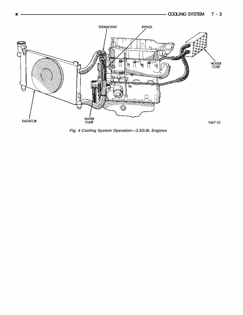
Fig. 4 Cooling System Operation—3.3/3.8L Engines
. COOLING SYSTEM 7 - 3
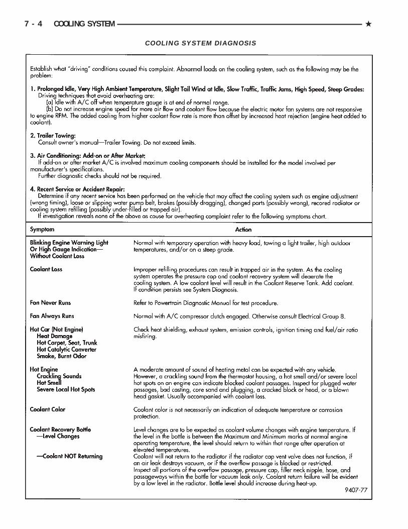
COOLING SYSTEM DIAGNOSIS
7 - 4 COOLING SYSTEM .
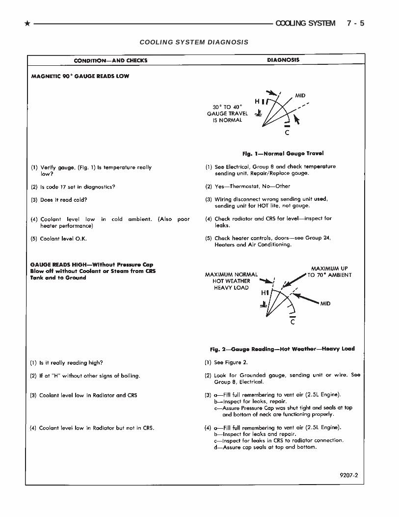
COOLING SYSTEM DIAGNOSIS
. COOLING SYSTEM 7 - 5

COOLING SYSTEM DIAGNOSIS
7 - 6 COOLING SYSTEM .

COOLING SYSTEM DIAGNOSIS
. COOLING SYSTEM 7 - 7

COOLING SYSTEM DIAGNOSIS
7 - 8 COOLING SYSTEM .
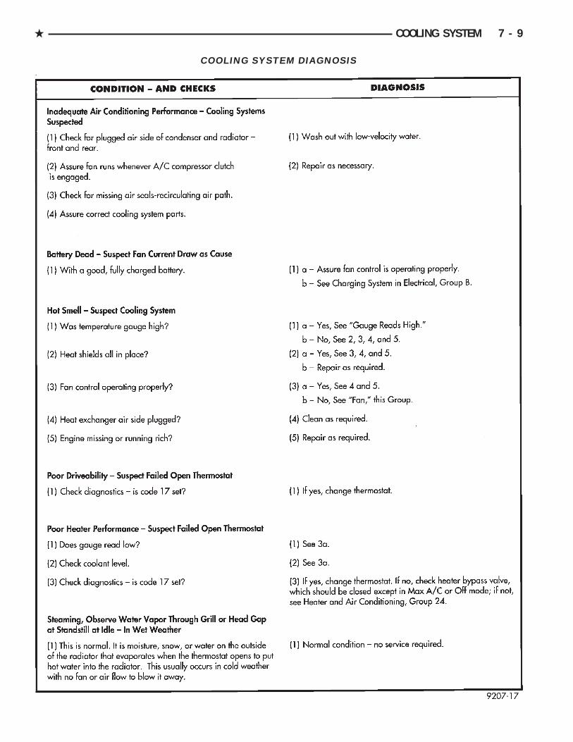
COOLING SYSTEM DIAGNOSIS
. COOLING SYSTEM 7 - 9
SERVICE PROCEDURES
WATER PUMPSA quick test to tell whether the pump is working is
to see if the heater warms properly. A defective pumpcan not circulate heated coolant through the longheater hose.
The water pump on all models can be re-placed without discharging the air conditioningsystem.
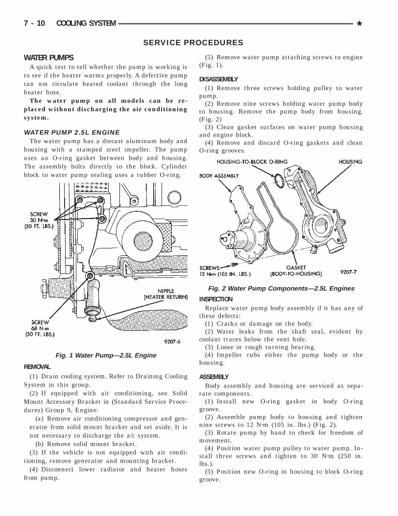
WATER PUMP 2.5L ENGINEThe water pump has a diecast aluminum body and
housing with a stamped steel impeller. The pumpuses an O-ring gasket between body and housing.The assembly bolts directly to the block. Cylinderblock to water pump sealing uses a rubber O-ring.
REMOVAL(1) Drain cooling system. Refer to Draining Cooling
System in this group.(2) If equipped with air conditioning, see Solid
Mount Accessory Bracket in (Standard Service Proce-dures) Group 9, Engine:
(a) Remove air conditioning compressor and gen-erator from solid mount bracket and set aside. It isnot necessary to discharge the a/c system.
(b) Remove solid mount bracket.(3) If the vehicle is not equipped with air condi-
tioning, remove generator and mounting bracket.(4) Disconnect lower radiator and heater hoses
from pump.
(5) Remove water pump attaching screws to engine(Fig. 1).
DISASSEMBLY(1) Remove three screws holding pulley to water
pump.(2) Remove nine screws holding water pump body
to housing. Remove the pump body from housing.(Fig. 2)
(3) Clean gasket surfaces on water pump housingand engine block.
(4) Remove and discard O-ring gaskets and cleanO-ring grooves.
INSPECTIONReplace water pump body assembly if it has any of
these defects:(1) Cracks or damage on the body.(2) Water leaks from the shaft seal, evident by
coolant traces below the vent hole.(3) Loose or rough turning bearing.(4) Impeller rubs either the pump body or the
housing.
ASSEMBLYBody assembly and housing are serviced as sepa-
rate components.(1) Install new O-ring gasket in body O-ring
groove.(2) Assemble pump body to housing and tighten
nine screws to 12 Nzm (105 in. lbs.) (Fig. 2).(3) Rotate pump by hand to check for freedom of
movement.(4) Position water pump pulley to water pump. In-
stall three screws and tighten to 30 Nzm (250 in.lbs.).
(5) Position new O-ring in housing to block O-ringgroove.
Fig. 1 Water Pump—2.5L Engine
Fig. 2 Water Pump Components—2.5L Engines
7 - 10 COOLING SYSTEM .

INSTALLATION(1) Install water pump on engine. Tighten top
three screws (Fig. 1) to 30 Nzm (250 in. lbs.). Installlower screw and tighten to 68 Nzm (50 ft. lbs.).
(2) Install bypass/heater hose and lower radiatorhose.
(3) Install generator and air conditioning compres-sor bracket(s). For solid mount bracket see standardservice procedures in Group 9 Engine.
(4) Install generator and air conditioning compres-sor.
(5) Refill cooling system. See Refilling CoolingSystem.
(6) Install drive belt, See Accessory Drive Belts,this Group.
WATER PUMP 3.0L ENGINEThe pump bolts directly to the engine block, using
a gasket for pump to block sealing (Fig. 3). The pumpis serviced as a unit.
The water pump is driven by the timing belt. SeeTiming System in Group 9, Engine for component re-moval providing access to water pump.
REMOVAL(1) Drain cooling system. Refer to Draining Cooling
System in this group.(2) Remove mounting bolts.(3) Separate pump from water inlet pipe (Figs. 3
and 4) and remove.
INSPECTIONReplace the water pump if it has any of the follow-
ing defects.(1) Damage or cracks on the pump body.(2) Coolant leaks, if the shaft seal is leaking, evi-
dent by traces of coolant leaks from vent hole A in(Fig. 4).
(3) Impeller rubs the inside of pump.(4) Loose or rough turning bearing.
INSTALLATION(1) Clean all gasket and O-ring surfaces on pump
and water pipe inlet tube.(2) Install new O-ring on water inlet pipe (Fig. 5).
Wet the O-ring (with water) to ease assembly.
CAUTION: Keep the O-ring free of oil or grease.
(3) Install new gasket on water pump and installpump inlet opening over water pipe, press assemblyto cause water pipe insertion into pump housing.
(4) Install pump to block mounting bolts andtighten to 27 Nzm (20 ft. lbs.).
(5) See Timing System in Engine, Group 9 and in-stall timing belt. Reassemble engine.
(6) Fill cooling system. See Refilling Cooling Sys-tem.
WATER PUMP 3.3/3.8L ENGINESThe pump has a die cast aluminum body and a
stamped steel impeller. It bolts directly to the chaincase cover, using an O-ring for sealing. It is driven bythe back surface of the Poly-V Drive Belt.
Fig. 3 Water Pump—3.0L Engine
Fig. 4 Water Pump Inspection
Fig. 5 Water Pipe O-Ring
. COOLING SYSTEM 7 - 11
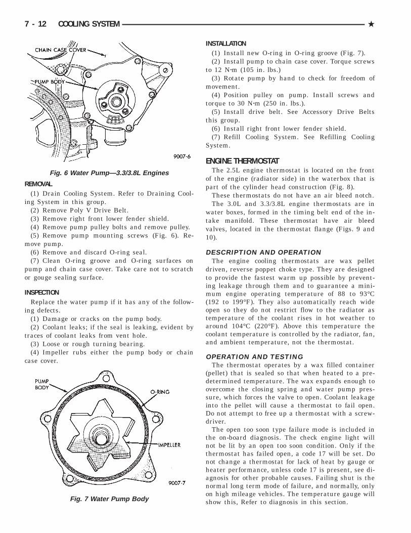
REMOVAL(1) Drain Cooling System. Refer to Draining Cool-
ing System in this group.(2) Remove Poly V Drive Belt.(3) Remove right front lower fender shield.(4) Remove pump pulley bolts and remove pulley.(5) Remove pump mounting screws (Fig. 6). Re-
move pump.(6) Remove and discard O-ring seal.(7) Clean O-ring groove and O-ring surfaces on
pump and chain case cover. Take care not to scratchor gouge sealing surface.
INSPECTIONReplace the water pump if it has any of the follow-
ing defects.(1) Damage or cracks on the pump body.(2) Coolant leaks; if the seal is leaking, evident by
traces of coolant leaks from vent hole.(3) Loose or rough turning bearing.(4) Impeller rubs either the pump body or chain
case cover.
INSTALLATION(1) Install new O-ring in O-ring groove (Fig. 7).(2) Install pump to chain case cover. Torque screws
to 12 Nzm (105 in. lbs.)(3) Rotate pump by hand to check for freedom of
movement.(4) Position pulley on pump. Install screws and
torque to 30 Nzm (250 in. lbs.).(5) Install drive belt. See Accessory Drive Belts
this group.(6) Install right front lower fender shield.(7) Refill Cooling System. See Refilling Cooling
System.
ENGINE THERMOSTATThe 2.5L engine thermostat is located on the front
of the engine (radiator side) in the waterbox that ispart of the cylinder head construction (Fig. 8).
These thermostats do not have an air bleed notch.The 3.0L and 3.3/3.8L engine thermostats are in
water boxes, formed in the timing belt end of the in-take manifold. These thermostat have air bleedvalves, located in the thermostat flange (Figs. 9 and10).
DESCRIPTION AND OPERATIONThe engine cooling thermostats are wax pellet
driven, reverse poppet choke type. They are designedto provide the fastest warm up possible by prevent-ing leakage through them and to guarantee a mini-mum engine operating temperature of 88 to 93°C(192 to 199°F). They also automatically reach wideopen so they do not restrict flow to the radiator astemperature of the coolant rises in hot weather toaround 104°C (220°F). Above this temperature thecoolant temperature is controlled by the radiator, fan,and ambient temperature, not the thermostat.
OPERATION AND TESTINGThe thermostat operates by a wax filled container
(pellet) that is sealed so that when heated to a pre-determined temperature. The wax expands enough toovercome the closing spring and water pump pres-sure, which forces the valve to open. Coolant leakageinto the pellet will cause a thermostat to fail open.Do not attempt to free up a thermostat with a screw-driver.
The open too soon type failure mode is included inthe on-board diagnosis. The check engine light willnot be lit by an open too soon condition. Only if thethermostat has failed open, a code 17 will be set. Donot change a thermostat for lack of heat by gauge orheater performance, unless code 17 is present, see di-agnosis for other probable causes. Failing shut is thenormal long term mode of failure, and normally, onlyon high mileage vehicles. The temperature gauge willshow this, Refer to diagnosis in this section.
Fig. 6 Water Pump—3.3/3.8L Engines
Fig. 7 Water Pump Body
7 - 12 COOLING SYSTEM .

REMOVAL(1) Drain cooling system down below the thermo-
stat level . Refer to Draining Cooling System in thisgroup.
(2) Remove thermostat housing bolts and housing(Figs. 8, 9 and 10).
(3) Remove thermostat, discard gasket and cleanboth gasket sealing surfaces.
INSTALLATION—2.5L ENGINEPlace a new gasket (dipped in clean water) on wa-
ter box surface, center thermostat in water box ongasket. Place housing over gasket and thermostat,making sure thermostat is in the thermostat hous-
ing. Bolt housing to water box (Fig. 8 ). Tighten boltsto 28 Nzm (250 in. lbs.). Refill cooling system (see Re-filling System).
INSTALLATION—3.0L ENGINECenter thermostat in water box pocket. Check that
the flange is seated correctly in the countersunk por-tion of the intake manifold water box (Figs. 9 and10). Install new gasket on water box. Install housingover gasket and thermostat and tighten bolts to 12Nzm (133 in. lbs.).
INSTALLATION—3.3/3.8L ENGINESPlace a new gasket (dipped in water) on the water
box surface, center thermostat into opening in the in-take manifold. Place housing over gasket and ther-
Fig. 8 Thermostat, Housing, and Water Box—2.5LEngine
Fig. 9 Thermostat, Housing, and Water Box—3.0LEngine
Fig. 10 Thermostat Installed—3.0L Engine
Fig. 11 Thermostat, Housing and Waterbox—3.3/3.8LEngines
. COOLING SYSTEM 7 - 13

mostat, making sure thermostat is in recess provided(Fig. 11). Bolt housing to intake manifold, tightenbolts to 28 Nzm (250 in. lbs.). Refill cooling system(see Refilling System).
COOLANTThe cooling system is designed around the coolant.
The coolant must accept heat from engine metal, inthe cylinder head area near the exhaust valves. Thencarry this heat to the radiator where the tube/fin as-semblies of these components can give it up to theair.
PERFORMANCEPerformance is measurable. For heat transfer pure
water excels (Formula = 1 btu per minute for eachdegree of temperature rise for each pound of water).This formula is altered when necessary additives tocontrol boiling, freezing, and corrosion are added asfollows:• Pure Water (1 btu) boils at 100°C (212°F) andfreezes at 0°C (32°F)• 100 percent Glycol (.7 btu) can cause a hot engineand detonation and will lower the freeze point to-22°C (-8°F).• 50/50 Glycol and Water (.82 btu) is the recom-mended combination that provides a freeze point of-37°C(-35°F). The radiator, water pump, engine waterjacket, radiator pressure cap, thermostat, tempera-ture gauge, sending unit and heater are all designedfor 50/50 glycol.
Where required, a 56 percent glycol and 44 percentwater mixture will provide a freeze point of-59°C(-50°F).
CAUTION: Richer mixtures cannot be measuredwith field equipment that can lead to problems as-sociated with 100 percent glycol.
SELECTION AND ADDITIVESThe use of aluminum cylinder heads, intake mani-
folds, and water pumps requires special corrosionprotection. Mopar Antifreeze, Prestone II, Peak orantifreeze containing Alugard 340-2, or their equiva-lent is recommended for best engine cooling withoutcorrosion. When mixed only to a freeze point of-37°C(-35°F) to -59°C (-50°F). If it loses color or becomescontaminated, drain, flush, and replace with freshproperly mixed solution.
SERVICECoolant should be changed at 52,500 miles or three
years, whichever occurs first, then every two years or30,000 miles.
ROUTINE LEVEL CHECKDo not remove radiator cap for routine cool-
ant level inspections.The coolant reserve system provides a quick visual
method for determining the coolant level without re-moving the radiator cap. Simply observe, with theengine idling and warmed up to normal operatingtemperature, that the level of the coolant in the re-serve tank (Fig. 15) is between the minimum andmaximum marks.
ADDING ADDITIONAL COOLANTThe radiator cap should not be removed.
When additional coolant is needed to maintain thislevel, it should be added to the coolant reserve tank.Use only 50/50 mix of ethylene glycol type antifreezeand water.
SERVICE COOLANT LEVELThe cooling system is closed and designed to main-
tain coolant level to the top of the radiator.When servicing requires a coolant level check in
the radiator, the engine must be off and not underpressure. Drain several ounces of coolant from theradiator drain cock while observing the Coolant Re-covery System (CRS) Tank. Coolant level in the CRStank should drop slightly. Then remove the radiatorcap. The radiator should be full to the top. If not, andthe coolant level in the CRS tank is at the MIN markthere is an air leak in the CRS system. Check hoseor hose connections to the CRS tank, radiator fillerneck or the pressure cap seal to the radiator fillerneck for leaks.
LOW COOLANT LEVEL AERATIONLow coolant level in a cross flow radiator will
equalize in both tanks with engine off. With engineat running operating temperature the high pressureinlet tank runs full and the low pressure outlet tankdrops. If this level drops below the top of the trans-mission oil cooler, air will be sucked into the waterpump:• Transmission oil will become hotter.• High reading shown on the temperature gauge.• Air in the coolant can cause loss of flow throughthe heater.• Exhaust gas leaks into the coolant also can causethe same problems?
DEAERATIONAir can only be removed from the system by gath-
ering under the pressure cap. On the next heat up itwill be pushed past the pressure cap into the CRStank by thermal expansion of the coolant. It then es-capes to the atmosphere in the CRS tank and is re-placed with solid coolant on cool down.
7 - 14 COOLING SYSTEM .

COOLING SYSTEM DRAIN, CLEAN FLUSH ANDREFILL
Drain, flush, and fill the cooling system at themileage or time intervals specified in the Mainte-nance Schedule in this Group. If the solution is dirtyor rusty or contains a considerable amount of sedi-ment, clean and flush with a reliable cooling systemcleaner. Care should be taken in disposing of theused engine coolant from your vehicle. Check govern-mental regulations for disposal of used engine cool-ant.
DRAINING COOLING SYSTEMTo drain cooling system move temperature selector
for heater to full heat with engine running (to pro-vide vacuum for actuation). Without removing ra-diator pressure cap and with system not underpressure, Shut engine off and open draincock. Thecoolant reserve tank (Fig. 15) should empty first,then remove radiator pressure cap. (if not, see Test-ing Cooling System for leaks). To vent 2.5L engine re-move the plug above thermostat housing (Fig. 12). Tovent 3.3/3.8L engines remove the engine temperaturesending unit (Fig. 13).
Removal of a plug or other component is requiredbecause these thermostats do not have an air ventand prevents air flow through it. This allows thecoolant to drain from the engine block.
CLEANINGDrain cooling system (see: Draining Cooling Sys-
tem) and refill with clean water (see Refilling Cool-ing System). Run engine with radiator cap installeduntil upper radiator hose is hot. Stop engine anddrain water from system. If water is dirty, fill, runand drain system again until water runs clear.
REVERSE FLUSHINGReverse flushing of the cooling system, is the forc-
ing of water through the cooling system, using airpressure in a direction opposite to that of the normalflow of water. This is usually only necessary withvery dirty systems with some evidence of partialplugging.
RADIATORDrain cooling system and remove radiator hoses
from engine. Install suitable flushing gun in radiatorlower hose. Fill radiator with clean water and turnon air in short blasts.
CAUTION: Internal radiator pressure must not ex-ceed 138 kPa (20 psi) as damage to radiator may re-sult. Continue this procedure until water runs clear.
ENGINEDrain radiator (see: Draining Cooling System)
and remove hoses from radiator. Remove engine ther-mostat and reinstall thermostat housing. Install suit-able flushing gun to thermostat housing hose. Turnon water, and when engine is filled, turn on air, butno higher than 138 kPa (20 psi) in short blasts. Allowengine to fill between blasts of air. Continue this pro-cedure until water runs clean. Reinstall thermostatusing a new housing gasket. Fill cooling system (SeeRefilling).
CHEMICAL CLEANINGOne type of corrosion encountered with aluminum
cylinder heads is aluminum hydroxide deposits. Cor-rosion products are carried to the radiator and depos-ited when cooled off. They appear as dark grey whenwet and white when dry. This corrosion can be re-moved with a two part cleaner (oxalic acid and neu-tralizer) available in auto parts outlets. Followmanufacturers directions for use.
Fig. 12 Thermostat Housing Drain/Fill Plug—2.5LEngine
Fig. 13 Engine Temperature Sending Unit—3.3/3.8LEngines Drain/Fill
. COOLING SYSTEM 7 - 15

REFILLINGFirst clean system to remove old glycol, see Cooling
System Cleaning.Fill system, using antifreeze described in Coolant.
Fill 50of capacity with 100glycol. Then complete filling system with water.
The 2.5L engine requires venting by removal of theplug on top of the water box (Fig. 12). The 3.3/3.8Lengines require the removal of the Engine Tempera-ture Sending Unit on the front of the cylinder head(Fig. 13). When coolant reaches this hole;• Install vent plug and tighten to 20 Nzm (15 ft. lbs.)for 2.5L Engines.• Install Engine Temperature Sending Unit andtighten to 7 Nzm (60 in. lbs.) for 3.3/3.8L Engines.
Continue filling system until full, this provides bet-ter heater performance. Be careful not to spillcoolant on drive belts or the generator.
Fill coolant reserve system to at least the MAXmark with 50/50 solution. It may be necessary to addcoolant to the reserve tank after three or four warmup, cool down cycles to maintain coolant level be-tween the MAX and MIN mark. This will allowtrapped air to be removed from the system.
TESTING SYSTEM FOR LEAKSWith engine not running, wipe the radiator filler
neck sealing seat clean. The radiator should be full.Attach the Tester Radiator Pressure Tool to the ra-
diator, as shown in (Fig. 14) and apply 104 kPa (15psi) pressure. If the pressure drops more than 2 psiin 2 minutes inspect all points for external leaks.
All hoses, radiator and heater, should be shakenwhile at 104 kPa (15 psi) since some leaks occur onlywhile driving due to engine rock, etc.
If there are no external leaks, after the gauge dialshows a drop in pressure, detach the tester. Start en-gine and run the engine up to normal operating tem-perature to open the thermostat and allow thecoolant to expand. Reattach the tester. If the needleon the dial fluctuates it indicates a combustion leak,usually a head gasket leak.
WARNING: WITH TOOL IN PLACE, PRESSURE WILLBUILDS UP FAST. EXCESSIVE PRESSURE BUILTUP, BY CONTINUOUS ENGINE OPERATION, MUSTBE RELEASED TO A SAFE PRESSURE POINT.NEVER PERMIT PRESSURE TO EXCEED 138 KPA(20 PSI).
If the needle on the dial does not fluctuate, racethe engine a few times. If an abnormal amount ofcoolant or steam emits from the tail pipe, it may in-dicate a coolant leak caused by a faulty head gasket,cracked engine block, or cracked cylinder head.
There may be internal leaks that can be deter-mined by removing the oil dip-stick. If water globules
appear intermixed with the oil it will indicate an in-ternal leak in the engine. If there is an internal leak,the engine must be disassembled for repair.
COOLANT RECOVERY SYSTEM (CRS)This system works with the radiator pressure cap
to use thermal expansion and contraction of the cool-ant to keep the coolant free of trapped air. Provides aconvenient and safe method for checking coolantlevel and adjusting level at atmospheric pressurewithout removing the radiator pressure cap. It alsoprovides some reserve coolant to cover minor leaksand evaporation or boiling losses. All vehicles areequipped with this system and take various shapesand forms. (Fig. 15) shows a typical system in thetypical location.
Fig. 14 Pressure Testing Cooling System
Fig. 15 Typical Coolant Recovery System
7 - 16 COOLING SYSTEM .

See Coolant Level Check Service and Deaeration,and Pressure Cap sections for operation and service.Vehicles equipped with the electric monitor systemhave a level sensor in the CRS tank, see Group 8,Electrical, for service.
RADIATOR PRESSURE CAPRadiators are equipped with a pressure cap that
releases pressure at some point within a range of 97-124 kPa (14-18 psi).
The system will operate at higher than atmo-spheric pressure that raises the coolant boiling pointallowing increased radiator cooling capacity.
There is also a vent valve in the center of the cap.This valve also opens when coolant is cooling andcontracting allowing coolant to return to radiatorfrom coolant reserve system tank by vacuum throughconnecting hose. If valve is stuck shut, the radia-tor hoses will be collapsed on cool down. Cleanthe vent valve (Fig. 16) to ensure proper sealingwhen boiling point is reached.
The gasket in the cap seals the filler neck, so thatvacuum can be maintained, allowing coolant to bedrawn back into the radiator from the reserve tank.
RADIATOR CAP TO FILLER NECK SEALPRESSURE RELIEF CHECK
The pressure cap upper gasket (seal) pressure re-lief can be checked by removing the overflow hose atthe radiator filler neck nipple (Fig. 16). Attach theRadiator Pressure Tool to the filler neck nipple andpump air into the radiator. Pressure cap upper gas-ket should relieve at 69-124 kPa (10-18 psi) and holdpressure at 55 kPa (8 psi) minimum.
WARNING: THE WARNING WORDS DO NOT OPENHOT ON THE RADIATOR PRESSURE CAP IS ASAFETY PRECAUTION. WHEN HOT, PRESSUREBUILDS UP IN COOLING SYSTEM. TO PREVENTSCALDING OR INJURY, THE RADIATOR CAPSHOULD NOT BE REMOVED WHILE THE SYSTEMIS HOT OR UNDER PRESSURE.
There is no need to remove the radiator cap at anytime except for the following purposes:
(1) Check and adjust antifreeze freeze point.(2) Refill system with new anti-freeze.(3) Conducting service procedures.(4) Checking for vacuum leaks.
WARNING: IF VEHICLE HAS BEEN RUN RECENTLY,WAIT 15 MINUTES BEFORE REMOVING CAP. THENPLACE A SHOP TOWEL OVER THE CAP AND WITH-OUT PUSHING DOWN ROTATE COUNTER-CLOCK-WISE TO THE FIRST STOP. ALLOW FLUIDS TOESCAPE THROUGH THE OVERFLOW TUBE ANDWHEN THE SYSTEM STOPS PUSHING COOLANTAND STEAM INTO THE CRS TANK AND PRESSUREDROPS PUSH DOWN AND REMOVE THE CAP COM-PLETELY. SQUEEZING THE RADIATOR INLET HOSEWITH A SHOP TOWEL (TO CHECK PRESSURE) BE-FORE AND AFTER TURNING TO THE FIRST STOPIS RECOMMENDED.
PRESSURE TESTING RADIATOR CAPDip the pressure cap in water, clean any deposits
off the vent valve or its seat and apply cap to end ofRadiator Pressure Tool. Working the plunger, bringthe pressure to 104 kPa (15 psi) on the gauge. If thepressure cap fails to hold pressure of at least 97 kPa(14 psi) replace cap. See CAUTION.
If the pressure cap tests properly while positionedon Radiator Pressure Tool (Fig. 17), but will not holdpressure or vacuum when positioned on the radiator.Inspect the radiator filler neck and cap top gasket forirregularities that may prevent the cap from sealingproperly.
CAUTION: Radiator Pressure Tool is very sensitiveto small air leaks that will not cause cooling systemproblems. A pressure cap that does not have a his-tory of coolant loss should not be replaced just be-cause it leaks slowly when tested with this tool.Add water to the tool. Turn tool upside down andrecheck pressure cap to confirm that cap is bad.
Fig. 16 Radiator Pressure Cap Filler Neck
Fig. 17 Pressure Testing Radiator Cap
. COOLING SYSTEM 7 - 17

INSPECTIONHold the cap in hand, right side up (Fig. 16). The
vent valve at the bottom of the cap should open. Ifthe rubber gasket has swollen and prevents the valvefrom opening, replace the cap.
Hold the cleaned cap in hand upside down. If anylight shows between vent valve and rubber gasket,replace cap. Do not use a replacement cap thathas a spring to hold the vent shut.
Replacement cap must be of the type designed forcoolant reserve system with a completely sealed dia-
phragm spring, and rubber gasket to seal to fillerneck top surface. This design assures coolant returnto radiator.
RADIATORThe radiators are cross-flow types (horizontal
tubes) with design features that provide greaterstrength also sufficient heat transfer capabilities tokeep the engine satisfactorily cooled (Figs. 1 and 2).
Fig. 1 Cooling Module—Standard Duty
Fig. 2 Cooling Module—Heavy Duty Trailer Tow
7 - 18 COOLING SYSTEM .
CAUTION: Plastic tanks, while stronger then brassare subject to damage by impact, such as wrenchesetc., or by excessive torque on hose clamps.
If the plastic tank is damage, replace the radiator.
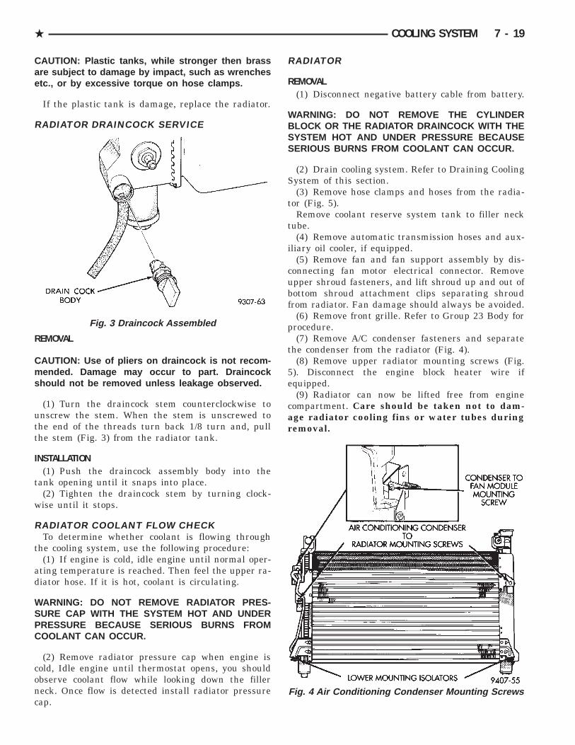
RADIATOR DRAINCOCK SERVICE
REMOVAL
CAUTION: Use of pliers on draincock is not recom-mended. Damage may occur to part. Draincockshould not be removed unless leakage observed.
(1) Turn the draincock stem counterclockwise tounscrew the stem. When the stem is unscrewed tothe end of the threads turn back 1/8 turn and, pullthe stem (Fig. 3) from the radiator tank.
INSTALLATION(1) Push the draincock assembly body into the
tank opening until it snaps into place.(2) Tighten the draincock stem by turning clock-
wise until it stops.
RADIATOR COOLANT FLOW CHECKTo determine whether coolant is flowing through
the cooling system, use the following procedure:(1) If engine is cold, idle engine until normal oper-
ating temperature is reached. Then feel the upper ra-diator hose. If it is hot, coolant is circulating.
WARNING: DO NOT REMOVE RADIATOR PRES-SURE CAP WITH THE SYSTEM HOT AND UNDERPRESSURE BECAUSE SERIOUS BURNS FROMCOOLANT CAN OCCUR.
(2) Remove radiator pressure cap when engine iscold, Idle engine until thermostat opens, you shouldobserve coolant flow while looking down the fillerneck. Once flow is detected install radiator pressurecap.
RADIATOR
REMOVAL(1) Disconnect negative battery cable from battery.
WARNING: DO NOT REMOVE THE CYLINDERBLOCK OR THE RADIATOR DRAINCOCK WITH THESYSTEM HOT AND UNDER PRESSURE BECAUSESERIOUS BURNS FROM COOLANT CAN OCCUR.
(2) Drain cooling system. Refer to Draining CoolingSystem of this section.
(3) Remove hose clamps and hoses from the radia-tor (Fig. 5).
Remove coolant reserve system tank to filler necktube.
(4) Remove automatic transmission hoses and aux-iliary oil cooler, if equipped.
(5) Remove fan and fan support assembly by dis-connecting fan motor electrical connector. Removeupper shroud fasteners, and lift shroud up and out ofbottom shroud attachment clips separating shroudfrom radiator. Fan damage should always be avoided.
(6) Remove front grille. Refer to Group 23 Body forprocedure.
(7) Remove A/C condenser fasteners and separatethe condenser from the radiator (Fig. 4).
(8) Remove upper radiator mounting screws (Fig.5). Disconnect the engine block heater wire ifequipped.
(9) Radiator can now be lifted free from enginecompartment. Care should be taken not to dam-age radiator cooling fins or water tubes duringremoval.
Fig. 3 Draincock Assembled
Fig. 4 Air Conditioning Condenser Mounting Screws
. COOLING SYSTEM 7 - 19

INSTALLATION(1) Slide radiator down into position behind radia-
tor support (yoke). Seat the radiator with the rubberisolators into the mount holes provided, with a 10lbs. force .
(2) Install the upper radiator mounting screws.Tighten radiator mounting bolts to 12 Nzm (105 in.lbs.) (Fig. 5).
(3) Install Air Conditioning Condenser onto the ra-diator (Fig. 4).
(4) Install front grille. Refer to Group 23 Body forprocedure.
(5) Connect automatic transmission hoses (ifequipped).
(6) Slide fan shroud, fan and motor down into clipson lower radiator tank. Attach upper shroud screws.
(7) Install upper, lower radiator hoses (includingcoolant reserve hose) (Fig. 5) and fan motor electricalconnection. See Refilling Cooling Systems.
(6) Connect negative battery cable.
RADIATOR HOSES AND CLAMPS
WARNING: IF VEHICLE HAS BEEN RUN RECENTLY,WAIT 15 MINUTES BEFORE WORKING ON VEHI-CLE. RELIEVE PRESSURE BY PLACING A SHOPTOWEL OVER THE CAP AND WITHOUT PUSHINGDOWN ROTATE IT COUNTER-CLOCKWISE TO THE
FIRST STOP. ALLOW FLUIDS TO ESCAPETHROUGH THE OVERFLOW TUBE AND WHEN THESYSTEM STOPS PUSHING OUT COOLANT ANDSTEAM AND PRESSURE DROPS.
The hoses are removed by using constant tensionclamp pliers to compress hose clamp.
A hardened, cracked, swollen or restricted hoseshould be replaced. Do not damage radiator inlet andoutlet when loosening hoses.
Radiator hoses should be routed without any kinksand indexed as designed. The use of molded hoses isrecommended.
Spring type hose clamps are used in all applica-tions. If replacement is necessary replace with theoriginal MOPAR equipment spring type clamp.
FANSAll models use electric motor driven cooling system
fan. The fan modules include a motor, shroud andfan. The module is fastened to the radiator by screws(Fig. 6).
All fan motors are two speed. Attempts to reducehigh temperature gauge reading by increasing enginespeed, at the same vehicle speed, can increase hightemperature.
Fig. 5 Engine Cooling Module Mounting—All Models
7 - 20 COOLING SYSTEM .

FAN MODULE SERVICEThere are no repairs to be made to the fan or sup-
port assembly. If the fan is warped, cracked, or oth-erwise damaged, it must be replaced as a assembly.
REMOVAL(1) Disconnect the fan motor electrical connector.(2) Remove upper shroud fasteners, and lift shroud
up and out of bottom shroud attachment clips sepa-rating shroud from radiator (Fig. 6). Fan damageshould always be avoided.
INSTALLATION(1) Install fan module assembly into attaching clips
on the bottom of the radiator (Fig. 6). Attach supportscrews tighten screws to 12 Nzm (105 in. lbs.).
(2) Connect fan motor lead. For wiring diagramsof fan motor systems refer to 8W Wiring Dia-grams.
RADIATOR FAN CONTROLFan control is accomplished two ways. A pressure
transducer on the compressor discharge line sends asignal to the powertrain control module (PCM) whichwill activate the fan. In addition to this control, thefan is turned on by the temperature of the coolantwhich is sensed by the coolant temperature sensorwhich sends the message to the Engine Controller.The Engine Controller turns on the fan through thefan relay. See Wiring Diagrams Manual for circuityand diagnostics provided.
Switching through the Powertrain Control Module(PCM) provides fan control for the following condi-tions;
Air Conditioning NOT ActivatedAll Engines:
• Low Speed Fan ON 104 °C (220 °F)• Low Speed Fan OFF 98.993 °C (210 °F)• High Speed Fan ON 110 °C (230 °F)• High Speed Fan OFF 104 °C (219 °F)
The fan will not run during cranking until the en-gine starts no matter what the coolant temperatureis.
TEMPERATURE GAUGE INDICATIONAt idle with Air Conditioning off the temperature
gauge will rise slowly to about 5/8 gauge travel, thefan will come on and the gauge will quickly drop toabout 1/2 gauge travel this is normal.
ELECTRIC FAN MOTOR
ELECTRIC FAN MOTOR TESTRefer to Powertrain Diagnostic Manual for proce-
dure
SERVICE
CAUTION: DO NOT DISASSEMBLE THE FAN MO-TOR FROM THE SUPPORT BRACKET.
Electric fan motor is serviced as an assembly withthe fan module.
For wiring diagrams of fan motor systems re-fer to 8W Wirig Diagrams.
AUTOMATIC TRANSMISSION OIL COOLERS
STANDARD DUTYThis style oil cooler is an internal oil to coolant
type mounted in the radiator side tank (Fig. 7). Thisstyle cooler uses rubber oil lines to feed oil to andfrom the cooler. Use only approved transmission oilcooler hose. Since these are molded to fit space avail-able, molded hoses are recommended.
Fig. 7 Transmission Oil Cooler—Standard Duty
Fig. 6 Fan Module
. COOLING SYSTEM 7 - 21

HEAVY DUTY TRAILER TOWIs a external oil-to-air type mounted ahead of the
radiator (Fig. 8). This style cooler uses rubber oillines to feed oil from the internal cooler to the exter-nal and then to the automatic transmission. Use onlyapproved transmission oil cooler hose. Since theseare molded to fit space available, molded hoses arerecommended.
Fig. 8 Transmission Oil Cooler—Heavy Duty TrailerTow
7 - 22 COOLING SYSTEM .

ACCESSORY DRIVE BELTS
INDEX
page page
2.5L Engine Belts Remove/Install-Adjust . . . . . . . . 243.0L Engine Belts Remove/Install-Adjust . . . . . . . . 253.3/3.8L Engines Accessory Drive Belt Remove/
Install . . . . . . . . . . . . . . . . . . . . . . . . . . . . . . . . 25
General Information . . . . . . . . . . . . . . . . . . . . . . . 23
GENERAL INFORMATION
PROPER BELT TENSIONSatisfactory performance of the belt driven accesso-
ries depends on proper belt tension. Belt tensioningshould be performed with the aid of a Burroughsgauge Special Tool C-4162. Because of space limita-tions in the engine compartment of front wheel drivevehicles, the gauge may be restricted to use after thevehicle has been raised on a hoist and the splashshield has been removed.
Belt tensioning methods are given in order of pref-erence:• Belt tension gauge method.• Torque equivalent method.
BELT TENSION GAUGE METHODUse belt tensioning Special Tool Kit C-4162 for:
CAUTION: The Burroughs gauge for the Poly-V beltis not to be used on the V-belt. These gauges arenot interchangeable.
• For conventional V-belts affix the Burroughs gauge(Special Tool C-4162) to the belt. Adjust the belt ten-sion for New or Used belt as prescribed in the BeltTension Chart. For a Poly-V belt affix the Poly-VBurroughs gauge to the belt and then apply specifiedtension to the belt as prescribed in the Belt TensionChart
Adjust the belt tension for a New or Used belt asprescribed in the Belt Tension Chart.
TORQUE EQUIVALENT METHODAdjustable accessory brackets provided with a
13mm (1/2 in.) square hole for a torque wrench canuse an equivalent torque value for belt adjustment.
Equivalent torque values for adjusting these acces-sory drive belts are specified on the Belt TensionChart.
ACCESSORY DRIVE BELTS DIAGNOSIS
. COOLING SYSTEM 7 - 23
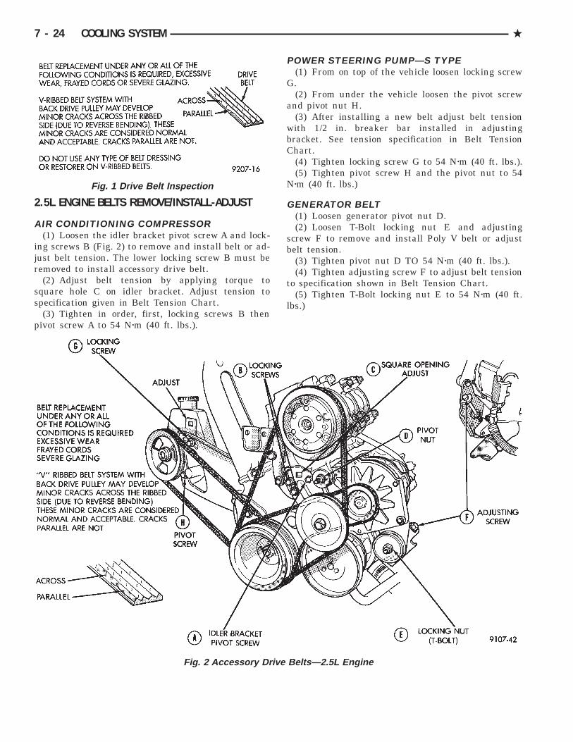
2.5L ENGINE BELTS REMOVE/INSTALL-ADJUST
AIR CONDITIONING COMPRESSOR(1) Loosen the idler bracket pivot screw A and lock-
ing screws B (Fig. 2) to remove and install belt or ad-just belt tension. The lower locking screw B must beremoved to install accessory drive belt.
(2) Adjust belt tension by applying torque tosquare hole C on idler bracket. Adjust tension tospecification given in Belt Tension Chart.
(3) Tighten in order, first, locking screws B thenpivot screw A to 54 Nzm (40 ft. lbs.).
POWER STEERING PUMP—S TYPE(1) From on top of the vehicle loosen locking screw
G.(2) From under the vehicle loosen the pivot screw
and pivot nut H.(3) After installing a new belt adjust belt tension
with 1/2 in. breaker bar installed in adjustingbracket. See tension specification in Belt TensionChart.
(4) Tighten locking screw G to 54 Nzm (40 ft. lbs.).(5) Tighten pivot screw H and the pivot nut to 54
Nzm (40 ft. lbs.)
GENERATOR BELT(1) Loosen generator pivot nut D.(2) Loosen T-Bolt locking nut E and adjusting
screw F to remove and install Poly V belt or adjustbelt tension.
(3) Tighten pivot nut D TO 54 Nzm (40 ft. lbs.).(4) Tighten adjusting screw F to adjust belt tension
to specification shown in Belt Tension Chart.(5) Tighten T-Bolt locking nut E to 54 Nzm (40 ft.
lbs.)
Fig. 1 Drive Belt Inspection
Fig. 2 Accessory Drive Belts—2.5L Engine
7 - 24 COOLING SYSTEM .

3.0L ENGINE BELTS REMOVE/INSTALL-ADJUST
AIR CONDITIONING BELTTo remove and install the air conditioning compres-
sor drive belt, first loosen the idler pulley lock nut,then turn the adjusting screw to raise or lower theidler pulley (Figs. 3 and 4).
To adjust the air conditioning drive belt,loosen the idler pulley nut (Fig. 3) and adjust belttension by tightening adjusting screw (Figs. 3 and 4).Tighten pulley nut to 54 Nzm (40 ft. lbs.) after adjust-ment.
GENERATOR/POWER STEERING PUMP BELTThe Poly-V generator/power steering pump belt is
provided with a dynamic tensioner (Fig. 5) to main-tain proper belt tension. To remove or install thisbelt, apply force in a clockwise direction to the ten-sioner pulley bolt (Fig. 5).
3.3/3.8L ENGINES ACCESSORY DRIVE BELTREMOVE/INSTALL
GENERATOR, POWER STEERING PUMP, AIRCONDITIONING COMPRESSOR AND WATERPUMP DRIVE BELT
The Poly-V Drive belt is provided with a dynamictensioner (Fig. 6) to maintain proper belt tension. Toremove or install this belt.
(1) Raise vehicle on hoist.(2) Remove right front splash shield.(3) Release tension by rotating the tensioner clock-
wise (Fig. 6).(4) Reverse above procedure to install.
Fig. 4 Air Conditioning Belt Idler
Fig. 5 Release Belt Tensioner
Fig. 6 Accessory Drive Belt—3.3/3.8L Engines
Fig. 3 Accessory Drive Belts—3.0L Engine
. COOLING SYSTEM 7 - 25

ENGINE BLOCK HEATER
DESCRIPTION AND OPERATIONOn all models an engine block heater is available
as an optional accessory. The heater is operated byordinary house current (110 Volt A.C.) through apower cord located behind the radiator grille. Thisprovides easier engine starting and faster warm-upwhen vehicle is operated in areas having extremelylow temperatures. The heater is mounted in a corehole (in place of a core hole plug) in the engine block,with the heating element immersed in coolant (Fig.7).
The power cord must be secured in its re-tainer clips, and not positioned so it could con-tact linkages or exhaust manifolds and becomedamaged.
If unit does not operate, trouble can be in eitherthe power cord or the heater element. Test powercord for continuity with a 110-volt voltmeter or 110-volt test light; test heater element continuity with anohmmeter or 12-volt test light.
REMOVAL(1) Drain coolant from radiator and cylinder block.
Refer to Cooling System Drain, Clean, Flush and Re-fill of this section for procedure.
(2) Detach power cord plug from heater.(3) Loosen screw in center of heater. Remove
heater assembly.
INSTALLATION(1) Thoroughly clean core hole and heater seat.(2) Insert heater assembly with element loop posi-
tioned upward.(3) With heater seated, tighten center screw se-
curely to assure a positive seal.(4) Fill cooling system with coolant to the proper
level, vent air, and inspect for leaks. Pressurize sys-tem with Radiator Pressure Tool before looking forleaks.
BELT TENSION CHART
7 - 26 COOLING SYSTEM .

Fig
.7
Blo
ckH
eate
rA
ssem
bly—
2.5L
,3.
0Lan
d3.
3/3.
8LE
ngin
es
. COOLING SYSTEM 7 - 27
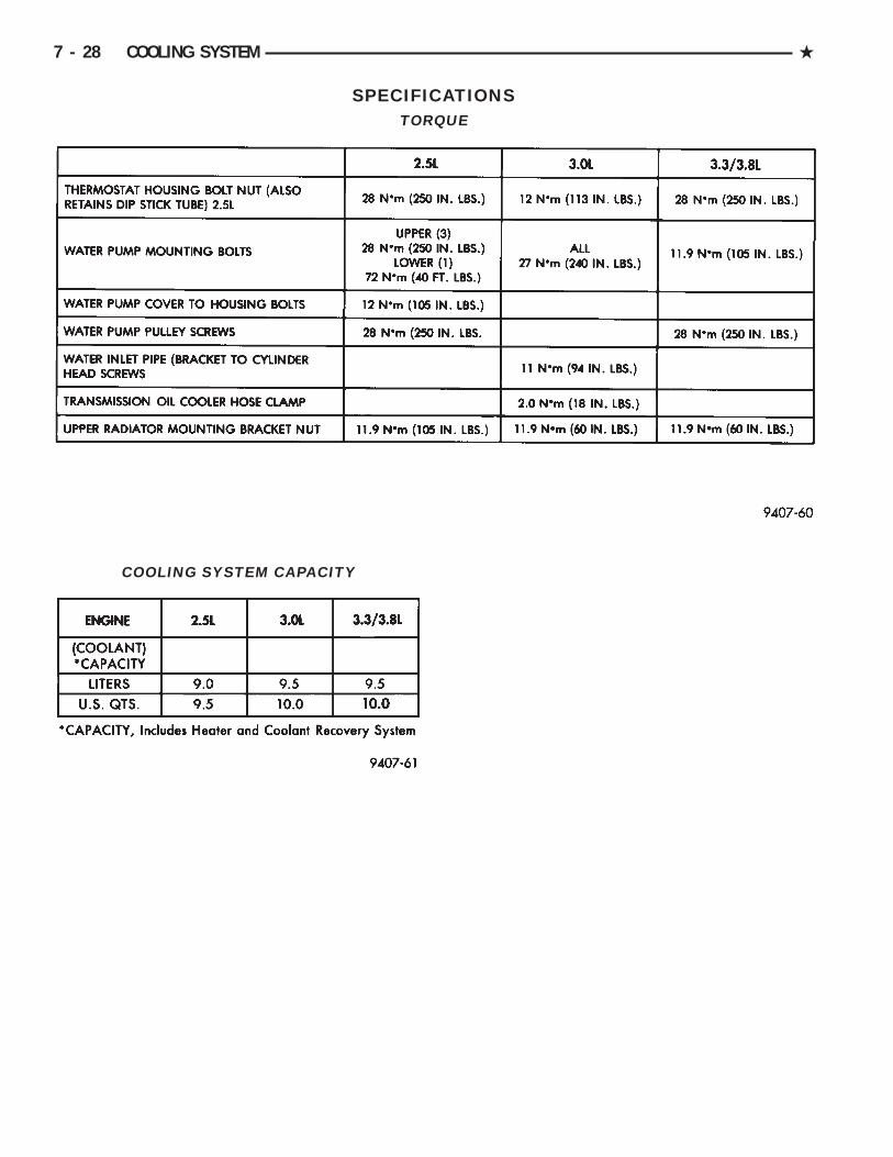
SPECIFICATIONS
COOLING SYSTEM CAPACITY
TORQUE
7 - 28 COOLING SYSTEM .