Guidance Marine Ltd, 5 Tiber Way, Meridian Business Park, Leicester LE19 1QP, UK www.guidance.eu.com T: +44 116 229 2600 E: [email protected] www.marine.direct RangeGuard Monopole Installer’s Guide W A R R A N T Y S e e o u r s t a n d a r d t e r m s o f s a le Q U A L I T Y A S S U R E D 3 YEAR

Welcome message from author
This document is posted to help you gain knowledge. Please leave a comment to let me know what you think about it! Share it to your friends and learn new things together.
Transcript

Guidance Marine Ltd, 5 Tiber Way, Meridian Business Park, Leicester LE19 1QP, UK www.guidance.eu.comT: +44 116 229 2600 E: [email protected] www.marine.direct
RangeGuard Monopole Installer’s Guide
W
A R R A NT
YSee our standard terms of s
ale
QU
ALITY ASSURED3YEAR
Guidance Marine Ltd,5 Tiber WayMeridian Business ParkLeicesterLE19 1QPUK
Tel: +44 116 229 2600
UK Support:+44 116 229 2665 (365 days a year, 08:00 - 20:00 hours UTC)[email protected]
USA Support: +1 504 305-1120 [email protected]
Asia Support: +65 6734 6365 [email protected]
Web: www.guidance.eu.com/customer-support
RangeGuard Monopole Installer’s GuideDocument No: 94-0523-4-A
Copyright © 2016 Guidance Marine Limited. All Rights Reserved.Copyright in the whole and every part of this document belongs to Guidance Marine Limited (the “Owner”) and may not be used, sold, transferred, copied or reproduced in whole or in part in any manner or form or in or on any media to any person other than in accordance with the terms of the Owner’s Agreement or otherwise without the prior written consent of the Owner. “RangeGuard Monopole“ is a trademark and “RangeGuard” is a registered trademark of Guidance Marine Ltd. ”Windows” is a trademark of Microsoft Corporation. All other brand or product names are trademarks or registered trademarks of their respective companies or organisations.
Serial No:
Date of Shipment from UK:
Server Software Version: Service Interface Software Version:
FCC ID: VYMRangeGuard
FCC Warning Statement
This device complies with Part 15 of the FCC (USA Federal Communications Commission) rules.
Operation is subject to the following two conditions:
1. This device may not cause harmful interference, and
2. This device must accept any interference received, including interference that may cause undesired operation.
This equipment complies with FCC radiation exposure limits set forth for an uncontrolled environment. End users must follow the specific operating instructions for satisfying RF exposure compliance. This transmitter must not be co-located or operating in conjunction with any other antenna or transmitter.
Changes or modifications not expressly approved by the party responsible.
Processing Unit IP Address:
0191 VYMRangeGuard

Document Number Changes Issue Date
94-0523-4-A RangeGuard Monopole Installer’s Guide 02/12/2016
Document History
3
IntroductionWelcome ................................................................................................................... 6System Overview ....................................................................................................... 7Serial Numbers and Software Versions ...................................................................... 8
Product Labels ..................................................................................................................8Software Version Information .............................................................................................8To Display the About System Pane ....................................................................................8
Installing the Sensor Hardware and SoftwareMounting the Sensor ............................................................................................... 11
Applications and Vessel Types .........................................................................................11Generic Mounting Guidelines ...........................................................................................11Mounting Offsets .............................................................................................................11Operating Region .............................................................................................................12Toe In Angle .....................................................................................................................12Sensor FOV .....................................................................................................................12Baseline ...........................................................................................................................12
Sensor Dimensions .................................................................................................. 13Processing Unit Dimensions .................................................................................... 14Mounting Template .................................................................................................. 15Cable Routing Diagram - Direct Connection ............................................................ 16Cable Routing Diagrams - Processor and Monitor Options ...................................... 17Installing the Server Software ................................................................................... 18
Installing the Marine ProcessorInstalling RangeGuard Monopole Client Software onto a Type 3 Marine Processor .. 20
Configuring the RangeGuard SystemUsing the RangeGuard Service Interface .................................................................. 22Network Communication Settings ........................................................................... 23Vessel Definition ....................................................................................................... 25Sensor Definitions .................................................................................................... 29Blanking Limits ........................................................................................................ 30DP Feed Configuration ............................................................................................ 31Information Tabs ...................................................................................................... 32
AppendicesInternational Standards Compliance ........................................................................ 35Part Numbers .......................................................................................................... 36UPS and Cable Specifications ................................................................................. 37Installation Checklist ................................................................................................ 38Index ....................................................................................................................... 40
Table of Contents
4

This section provides an introduction and overview of the RangeGuard Monopole system. It contains the following pages:
• Welcome (page 6)
• System Overview (page 7)
• Serial Numbers and Software Versions (page 8)
Note that whilst we endeavour to describe system functionality correctly in this document, we do not guarantee that it exactly represents the version of the system that you are running, particularly after any future upgrades to the software.
Introduction
5
Welcome to the RangeGuard Monopole Installer’s Guide. It explains how to mount and install the RangeGuard Monopole system onto a vessel. For instructions on how to use the system, please see the RangeGuard Monopole Operator’s Guide (Doc No. 94-0522-4).
The Installing the Sensor Hardware and Software section on page 10 describes where to mount the RangeGuard sensors on the vessel, and how to connect them to the RangeGuard Monopole processing unit which in turn connects to the RangeGuard Monopole marine processor and the vessel’s DP system. It also explains how to upgrade the server software, if required.
The Installing the Marine Processor section on page 19 gives relevant information for mounting and setting up the marine processor and explains how to upgrade the RangeGuard Monopole Dashboard software, if required.
The Configuring the RangeGuard Monopole System section on page 21 explains how to configure the system for your vessel.
!NOTE: Installation of a RangeGuard Monopole system should be carried out by a suitably qualified and competent engineer.
Welcome
6
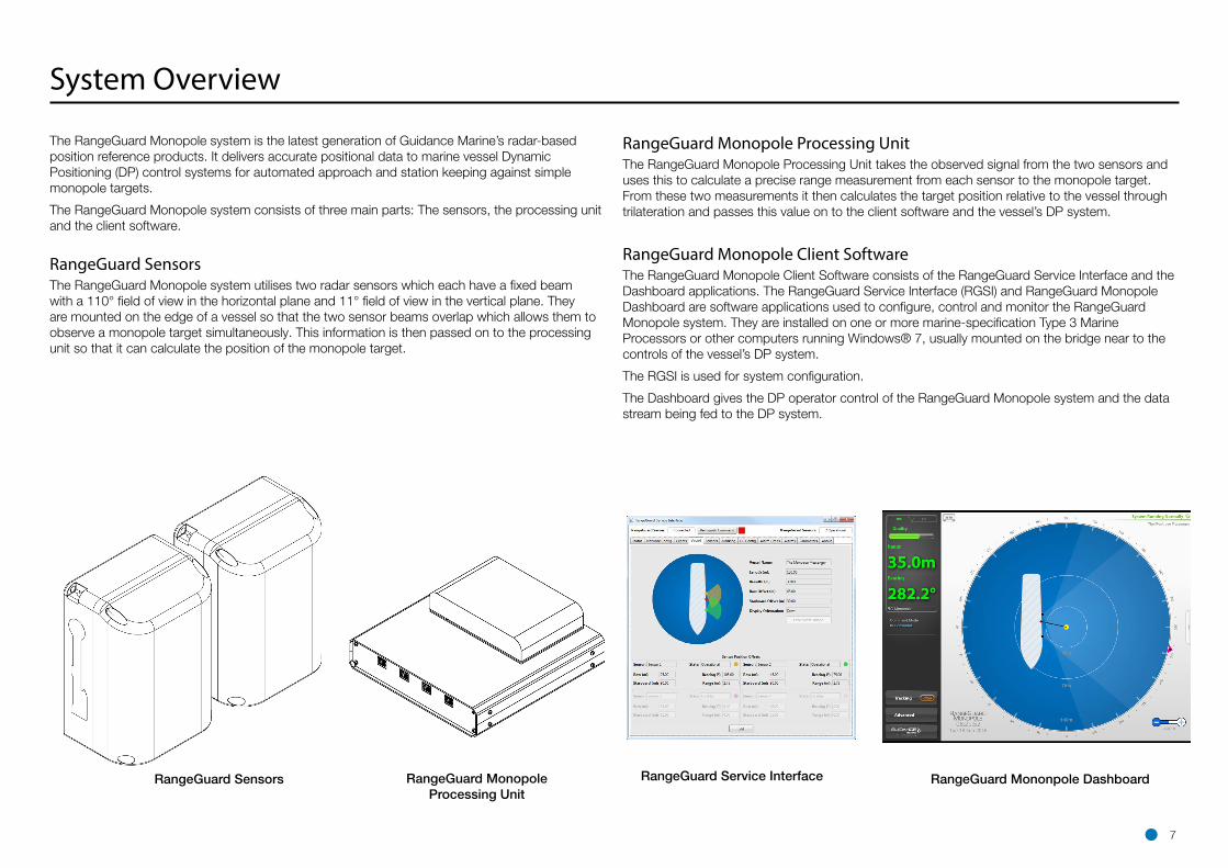
The RangeGuard Monopole system is the latest generation of Guidance Marine’s radar-based position reference products. It delivers accurate positional data to marine vessel Dynamic Positioning (DP) control systems for automated approach and station keeping against simple monopole targets.
The RangeGuard Monopole system consists of three main parts: The sensors, the processing unit and the client software.
RangeGuard SensorsThe RangeGuard Monopole system utilises two radar sensors which each have a fixed beam with a 110° field of view in the horizontal plane and 11° field of view in the vertical plane. They are mounted on the edge of a vessel so that the two sensor beams overlap which allows them to observe a monopole target simultaneously. This information is then passed on to the processing unit so that it can calculate the position of the monopole target.
System Overview
RangeGuard Monopole Processing UnitThe RangeGuard Monopole Processing Unit takes the observed signal from the two sensors and uses this to calculate a precise range measurement from each sensor to the monopole target. From these two measurements it then calculates the target position relative to the vessel through trilateration and passes this value on to the client software and the vessel’s DP system.
RangeGuard Monopole Client SoftwareThe RangeGuard Monopole Client Software consists of the RangeGuard Service Interface and the Dashboard applications. The RangeGuard Service Interface (RGSI) and RangeGuard Monopole Dashboard are software applications used to configure, control and monitor the RangeGuard Monopole system. They are installed on one or more marine-specification Type 3 Marine Processors or other computers running Windows® 7, usually mounted on the bridge near to the controls of the vessel’s DP system.
The RGSI is used for system configuration.
The Dashboard gives the DP operator control of the RangeGuard Monopole system and the data stream being fed to the DP system.
RangeGuard Sensors RangeGuard Monopole Processing Unit
RangeGuard Service Interface RangeGuard Mononpole Dashboard
7
Serial Numbers and Software Versions
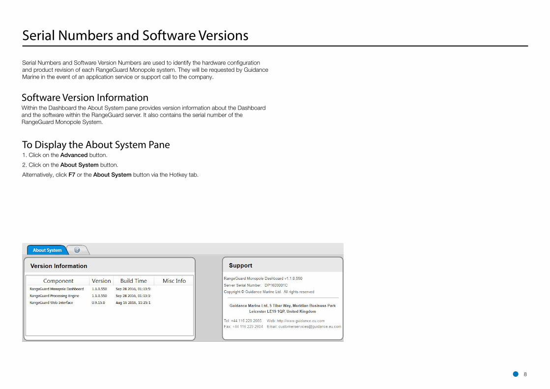
Software Version InformationWithin the Dashboard the About System pane provides version information about the Dashboard and the software within the RangeGuard server. It also contains the serial number of the RangeGuard Monopole System.
Serial Numbers and Software Version Numbers are used to identify the hardware configuration and product revision of each RangeGuard Monopole system. They will be requested by Guidance Marine in the event of an application service or support call to the company.
To Display the About System Pane1. Click on the Advanced button.
2. Click on the About System button.
Alternatively, click F7 or the About System button via the Hotkey tab.
8
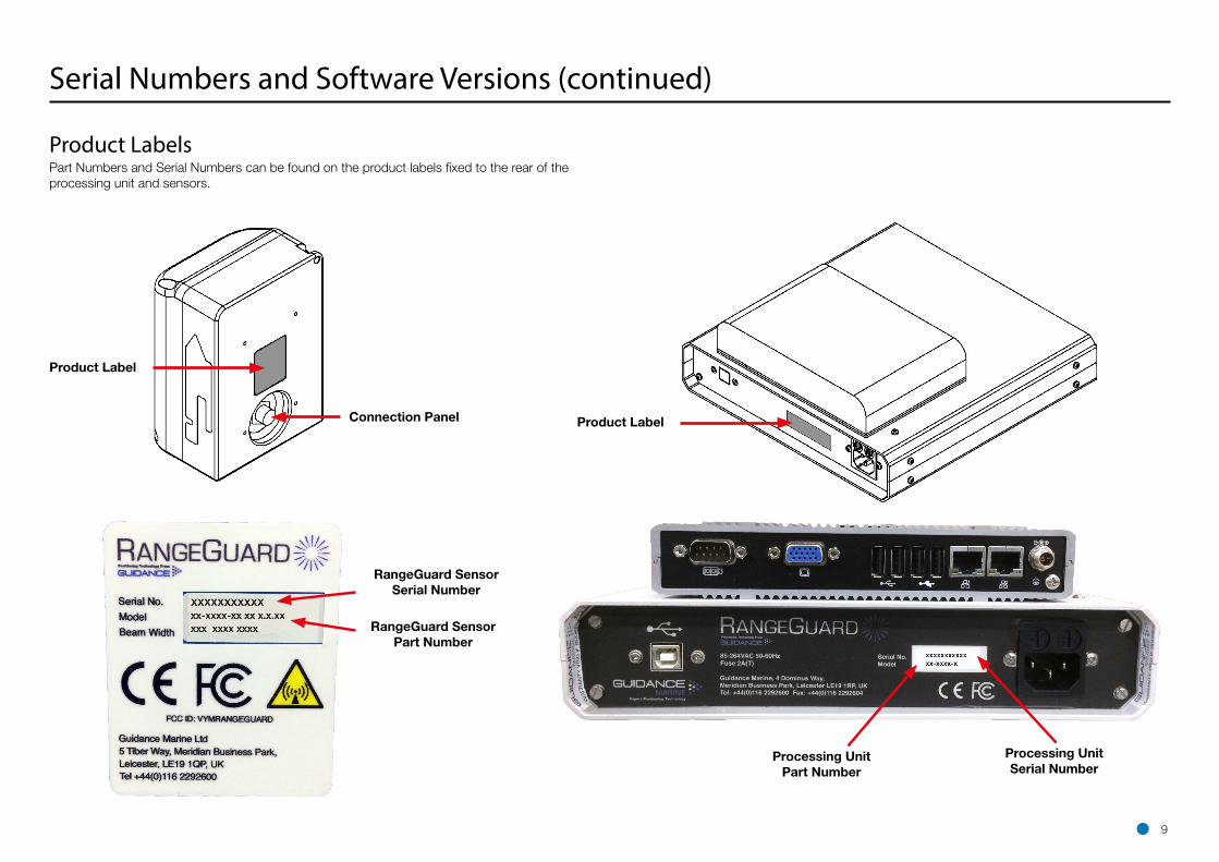
Product Label
Connection Panel
RangeGuard SensorPart Number
RangeGuard SensorSerial Number
Serial Numbers and Software Versions (continued)
Product LabelsPart Numbers and Serial Numbers can be found on the product labels fixed to the rear of the processing unit and sensors.
Processing UnitPart Number
Processing UnitSerial Number
Product Label
9
This section explains where and how to mount the RangeGuard Sensor on the vessel. It contains the following pages:
• Mounting the Sensors (page 11)
• Sensor Dimensions (page 13)
• Processing Unit Dimensions (page 14)
• Mounting Template (page 15)
• Cable Routing Diagram - Direct Connection (page 16)
• Cable Routing Diagrams - Processor and Monitor Options (page 17)
• Installing the Server Software (page 18)
10
Installing the Sensor Hardware and Software

Mounting the Sensors
Applications and Vessel TypesRangeGuard Monopole is only for use in environments where a vessel will be positioning itself relative to a monopole structure.
!NOTE: Usage in more complex environments can lead to unstable position measurements and is not supported by the system.
General Mounting GuidelinesThe sensors should be mounted:
• With an unobstructed view in the expected direction of the monopole structure (See diagram on the right).
• At a height above sea level such that the sensor field of view will intersect with the monopole target.
• Well above sea level to prevent swamping or immersion.
• Allowing for easy access to the connection port on the rear of the sensors (See Sensor Dimensions on page 13).
• In an upright position.
Mounting OffsetsThe orientation and position of each sensor on the vessel must be set up in the RGSI software. (See Bow and Starboard Offsets on page 27 and Bearing Offset on page 28).
Side ViewTop View
55°5.5°
Key:Keep areas marked clear of clutter e.g. vessel superstructure
5.5°55°
Unobstructed Sensor Field of View
11
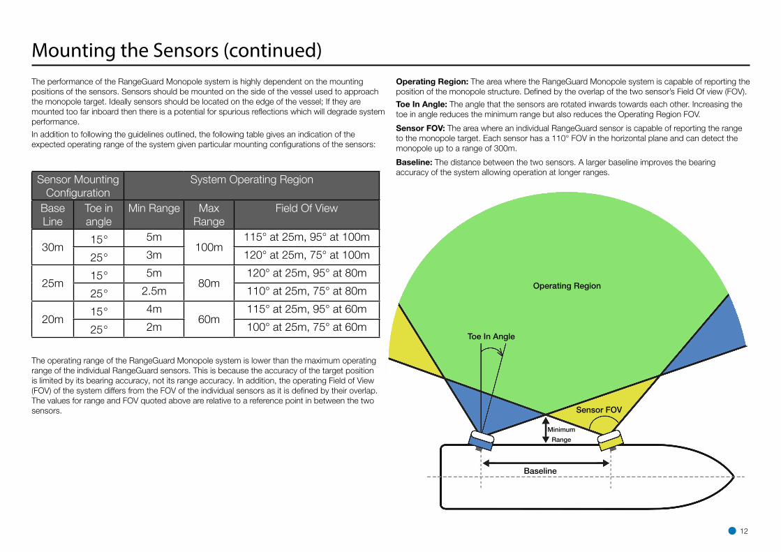
Mounting the Sensors (continued)The performance of the RangeGuard Monopole system is highly dependent on the mounting positions of the sensors. Sensors should be mounted on the side of the vessel used to approach the monopole target. Ideally sensors should be located on the edge of the vessel; If they are mounted too far inboard then there is a potential for spurious reflections which will degrade system performance.
In addition to following the guidelines outlined, the following table gives an indication of the expected operating range of the system given particular mounting configurations of the sensors:
Baseline
Sensor FOV
Toe In Angle
Operating Region
Operating Region: The area where the RangeGuard Monopole system is capable of reporting the position of the monopole structure. Defined by the overlap of the two sensor’s Field Of view (FOV).
Toe In Angle: The angle that the sensors are rotated inwards towards each other. Increasing the toe in angle reduces the minimum range but also reduces the Operating Region FOV.
Sensor FOV: The area where an individual RangeGuard sensor is capable of reporting the range to the monopole target. Each sensor has a 110° FOV in the horizontal plane and can detect the monopole up to a range of 300m.
Baseline: The distance between the two sensors. A larger baseline improves the bearing accuracy of the system allowing operation at longer ranges.
The operating range of the RangeGuard Monopole system is lower than the maximum operating range of the individual RangeGuard sensors. This is because the accuracy of the target position is limited by its bearing accuracy, not its range accuracy. In addition, the operating Field of View (FOV) of the system differs from the FOV of the individual sensors as it is defined by their overlap. The values for range and FOV quoted above are relative to a reference point in between the two sensors.
Minimum
Range
12
Sensor Mounting Configuration
System Operating Region
Base Line
Toe in angle
Min Range Max Range
Field Of View
30m15° 5m
100m115° at 25m, 95° at 100m
25° 3m 120° at 25m, 75° at 100m
25m15° 5m
80m120° at 25m, 95° at 80m
25° 2.5m 110° at 25m, 75° at 80m
20m15° 4m
60m 115° at 25m, 95° at 60m
25° 2m 100° at 25m, 75° at 60m
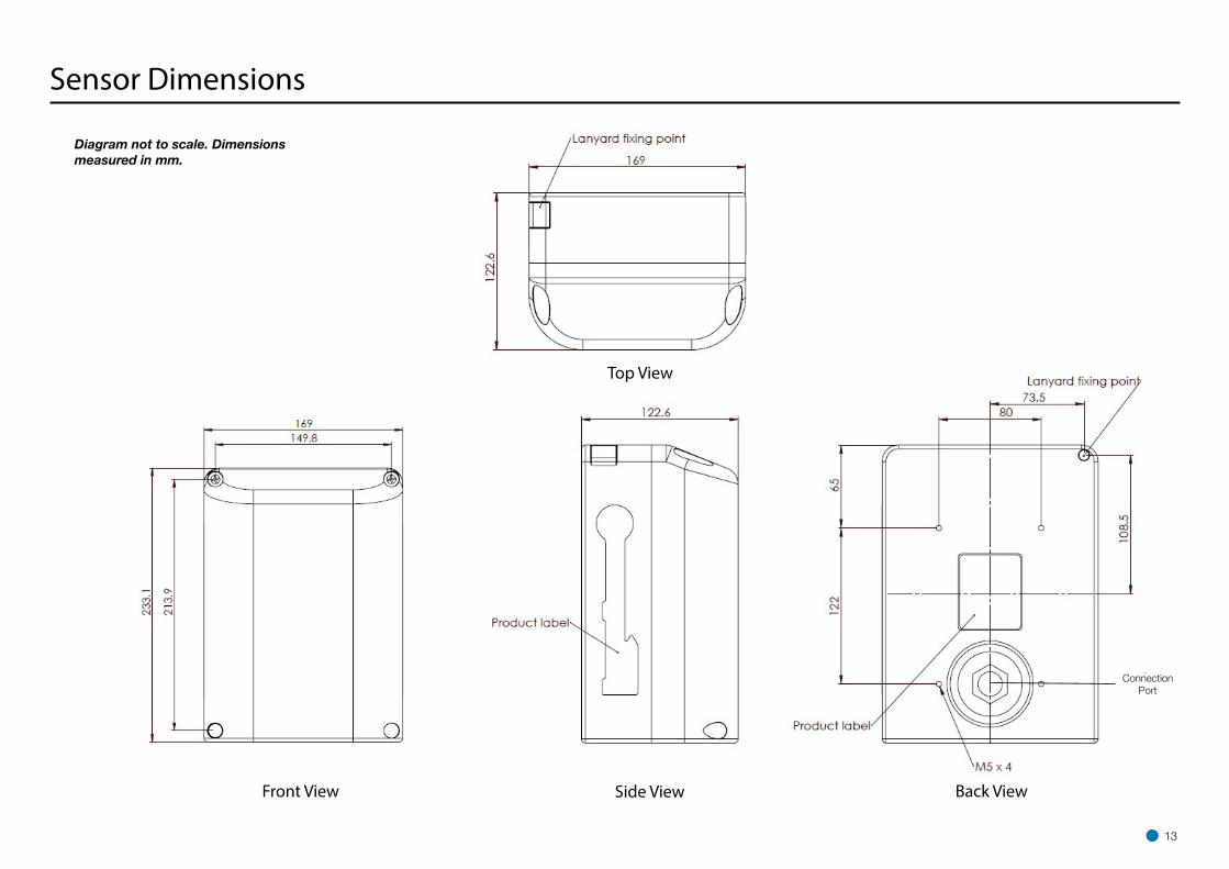
Sensor Dimensions
Diagram not to scale. Dimensions measured in mm.
13
Top View
Side ViewFront View Back View
Connection Port

Processing Unit Dimensions
250
254.80
180
92
55
254.60
250
180
250
121
.20
250
6.90 128.10
55 9
2
250
254.80
180
92
55
254.60
250
180
250
121
.20
250
6.90 128.10
55 9
2
250
254.80
180
92
55
254.60
250
180
250
121
.20
250
6.90 128.10
55 9
2
Diagram not to scale. Dimensions measured in mm.
14

Mounting Template
80
169
122
51.
50
70.
50
50
60
62.50
4.20
233
.06
Diagram not to scale. Dimensions measured in mm.
15
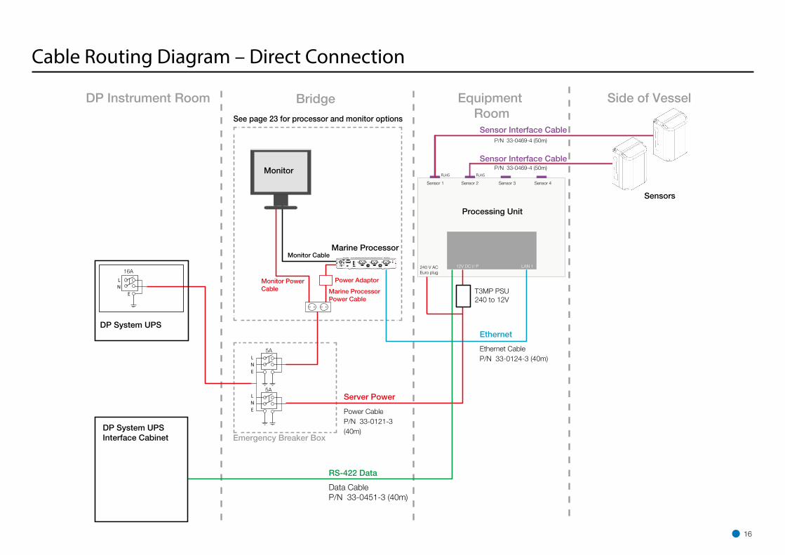
DP Instrument Room Bridge Equipment Room
Emergency Breaker Box
Ethernet
Server Power
RS-422 Data
Monitor Cable
Monitor Power Cable Marine Processor
Power Cable
Power Cable P/N 33-0121-3 (40m)
Data Cable P/N 33-0451-3 (40m)
Ethernet Cable P/N 33-0124-3 (40m)
16A
5A
5A
DP System UPS
DP System UPS Interface Cabinet
Monitor
Marine Processor
See page 23 for processor and monitor options
Power Adaptor
Side of Vessel
T3MP PSU240 to 12V
240 V ACEuro plug
12V DC I/ P LAN 1
Sensor 1 Sensor 2 Sensor 3 Sensor 4
RJ45 RJ45
Sensor Interface Cable
Processing Unit
P/N 33-0469-4 (50m)
P/N 33-0469-4 (50m)
Sensor Interface Cable
Sensors
16
Cable Routing Diagram – Direct Connection

Cable Routing Diagrams - Processor and Monitor Options
Alternative Processor and Monitor Options
Any of the following configurations may be used (see page 16)
Processor: Type 3 Marine Processor (Part Number 20-0231-0)
Monitor: 15” Desktop Monitor (Part Number 20-0115-1)
Marine Processor
Desktop Monitor
Monitor Power Cable
Monitor Cable
Power Adaptor
Marine Processor Power Cable
Marine Processor
Monitor Power Cable
Monitor Cable
Power Adaptor
Marine Processor Power Cable
Hatteland Touchscreen
Monitor
Processor: Type 3 Marine Processor (Part Number 20-0231-0)
Monitor: Hatteland Marine Touchscreen Monitor (Part Number 20-0211-4)
Optional brackets: Hatteland Mounting Bracket (Part Number 24-0259-4)
Hatteland VESA Bracket for Wall or Ceiling (Part Number 24-0258-4)
Power Cable
Processor and Monitor: HattelandPanel PC (Integrated PC and TouchscreenMonitor, Part Number 20-0182-1)
Optional brackets: Hatteland Mounting Bracket (Part Number 24-0259-4)
Hatteland VESA Bracket for Wall or Ceiling (Part Number 24-0258-4)
Hatteland Panel PC
EthernetEthernet Ethernet
17
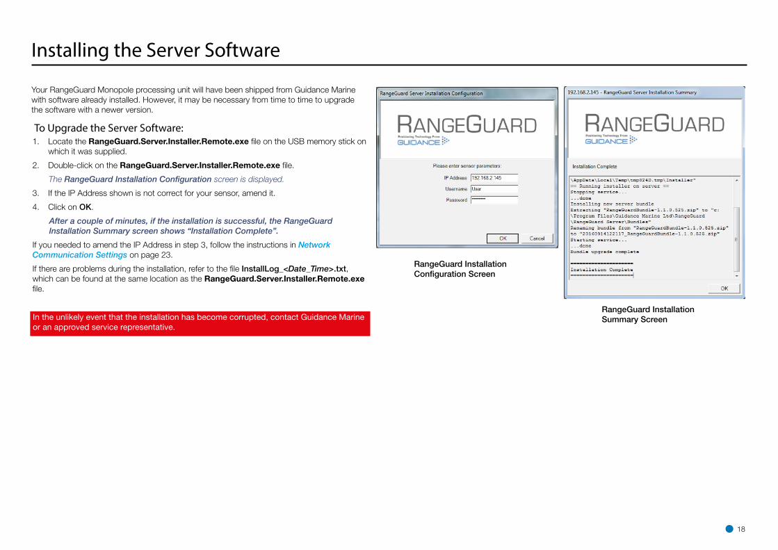
Your RangeGuard Monopole processing unit will have been shipped from Guidance Marine with software already installed. However, it may be necessary from time to time to upgrade the software with a newer version.
To Upgrade the Server Software:1. Locate the RangeGuard.Server.Installer.Remote.exe file on the USB memory stick on
which it was supplied.
2. Double-click on the RangeGuard.Server.Installer.Remote.exe file.
The RangeGuard Installation Configuration screen is displayed.
3. If the IP Address shown is not correct for your sensor, amend it.
4. Click on OK.
After a couple of minutes, if the installation is successful, the RangeGuard Installation Summary screen shows “Installation Complete”.
If you needed to amend the IP Address in step 3, follow the instructions in Network Communication Settings on page 23.
If there are problems during the installation, refer to the file InstallLog_<Date_Time>.txt, which can be found at the same location as the RangeGuard.Server.Installer.Remote.exe file.
RangeGuard Installation Configuration Screen
RangeGuard Installation Summary Screen
18
Installing the Server Software
In the unlikely event that the installation has become corrupted, contact Guidance Marine or an approved service representative.

19
Before setting up the RangeGuard Monopole client computer(s), refer to the relevant installation sheet(s) for dimensions and connection information:
For a Type 3 Marine Processor:
• 94-0465-4 Type 3 Marine Processor and Display Installation Sheet
For a Hatteland Panel PC:
• 94-0466-4 Hatteland Panel PC Installation Sheet
The following pages explain how to install the client software:
• Installing RangeGuard Monopole Client Software (page 20)
Installing the Marine Processor

Installing RangeGuard Monopole Client Software
This section explains how to install the RangeGuard Monopole client software onto a client PC (e.g. a Type 3 Marine Processor). If the client PC has been supplied by Guidance Marine, it will have been shipped with the client software already installed. If the client PC has not been supplied by Guidance Marine, then the Guidance Prerequisites should be installed before installing any client software. Contact Guidance Marine for instructions on how to acquire and complete the prerequisites installation. If you are upgrading to newer Versions of the RangeGuard Monopole client software, first uninstall the existing versions in the usual way, following on-screen prompts.
To Install the Client Software:1. Locate the RangeGuardMonopoleDashboardSetup.exe and RangeGuardServiceInterfaceSetup.
exe files on the USB memory stick on which they were supplied.
2. Double-click on the RangeGuardMonopoleDashboardSetup.exe file.
The Welcome screen is displayed.
3. Click on the Install button.
4. If a restart is required, click on the Restart button.
After the restart, the RangeGuard Monopole Dashboard Setup screen is displayed.
5. If required, change any of the settings from the default values shown.
6. Click on the OK button.
7. If a restart is required, click on the Restart button.
The installation process is complete following the restart.
8. Repeat steps 2...7 for RangeGuardServiceInterfaceSetup.exe.
Welcome Screen
RangeGuard Monopole Dashboard Setup Screen
Setup Successful Screen
!NOTE: The RangeGuard Service Interface should
only be installed onto one computer in the system. The Dashboard may be installed onto multiple computers.
Configuration SettingsWhen installing the Dashboard, adjust the following setings or allow to default:
Communications Parameters
Ensure that the sensor’s IP address is shown, otherwise enter “127.0.0.1” in order to run the Dashboard with a RangeGuard Emulator on the same computer.
Display
If the Enable Dashboard On-Screen Keyboard box is ticked, the On-Screen Keyboard (OSK) will pop up when you focus on a text or numerical entry field (typically used on a system without a keyboard).
20

Configuring the RangeGuard Monopole System
21
This section contains the following pages:
• Using the RangeGuard Service Interface (page 22)
• Network Communication Settings (page 23)
• Vessel Definition (page 25)
• Sensor Definitions (page 29)
• Blanking Limits (page 30)
• DP Feed Configuration (page 31)
• Information Tabs (page 32)

Using the RangeGuard Service InterfaceThe RangeGuard Service Interface (RGSI) is a tool for configuring the RangeGuard Monopole system.
To open the RangeGuard Service InterfaceEnsure that the system is powered on and connected to the control computer.
1. Double-click on the RGSI icon:
(Alternatively, run from the Start menu:
Start > All Programs > Guidance Marine Ltd > RangeGuard > RangeGuard Service Interface).
Screen Layout of the RGSIThe upper part of the RGSI window contains fields relating to communications, as follows:
RangeGuard Server Status - Indicates whether the RGSI is “Connected” to the server or “Disconnected”.
Take Command / Relinquish Command – This button allows the user to toggle the command mode of the RGSI between “In Command” and “Monitoring”.
Connect – Replaces Take Command / Relinquish Command when the RGSI is disconnected from the server, allowing re-connection.
In Command Indicator – This red block symbol is visible when the RGSI is “In Command”.
RangeGuard Sensor Status - Indicates the number of operational RangeGuard sensors currently connected to the processing unit.
The Status TabThe Status tab gives an overview of the operational state of the system; it contains the following fields:
Tracked By - Names of the sensors being used for tracking, blank when not tracking.
Tracking Info - Range and bearing to target, blank when not tracking.
Tracking State – Current system tracking state, either “Not Tracking” or “Tracking”.
The Status tab also includes status information for the individual sensors:
Sensor - Name of the sensor (configurable on the sensor tab)
State - Current sensor state, either “Operational”, “Not Operational” or “Disabled”. If this sensor is not “Operational” then all other fields will be blank.
Range - Range measurement to target, blank if no target is visible
Closing Speed - Speed of approach to target relative to sensor, blank if no target is visible.
Time to Contact - Time until sensor will make contact with target, “---” if moving away from target, blank if no target is visible.
22

Network Communication SettingsThe Network Config tab of the RGSI is used to view and amend the RGSI’s record of the server’s network IP address and also to remotely amend the address on board the server.
The default network IP address is 192.168.2.231 on the RangeGuard Processing Unit. If you do change the IP address of the Processing Unit, please make a note of new IP address in the spaces provided in this manual (See page 3 or 38). When the network IP address is changed the label should be updated with the new IP address.
!NOTE: Where the Dashboard and RGSI are installed on the same computer, they share a common record of the server’s network IP address. If it is amended using one application,
the other picks up the change when next opened.
To Modify the RGSI’s Record of the Server’s Network IP Address1. Click on the Network Config tab of the RGSI.
2. Click on the Disconnect button if the RGSI is connected to the server.
3. Click on the Edit button in the Service Interface to Server Communications section.
4. Amend the Server Address as required.
5. Click on Apply to save the changes or on Cancel to discard.
To Modify the Dashboard’s Record of the Server’s Network IP Address1. Click on the Guidance button to open the Guidance Home menu.
2. Click on Disconnect.
3. Navigate to Advanced > Comms Settings.
4. Click on Edit.
5. Amend the Address field as required.
6. Click on the Apply button to confirm.
23

Network Communication Settings (continued)
To Remotely Modify the Server’s On-Board Network IP Address1. Ensure that the RGSI is in command and that no tracking is in progress.
2. Click on the Network Config tab of the RGSI.
3. Click on the Edit button in the Server On-Board Network Configuration section.
4. Amend the Server Address as required.
5. Click on Apply to save the changes.
Communications between the RGSI and server are then lost as the server is updated. After a short period the RGSI will return to normal operation.
24

Vessel Definition
The Vessel tab allows you to define the dimensions of the vessel outline on the Bird’s Eye View (BEV) of the Dashboard, the name of the vessel and other items as follows:
• Vessel Name: The name of your ship. This is displayed beneath the primary system status near the top right corner of the Dashboard screen.
• Vessel Length: The distance from the bow to the stern of the vessel, in metres.
• Vessel Breadth: The width or beam of the vessel, in metres.
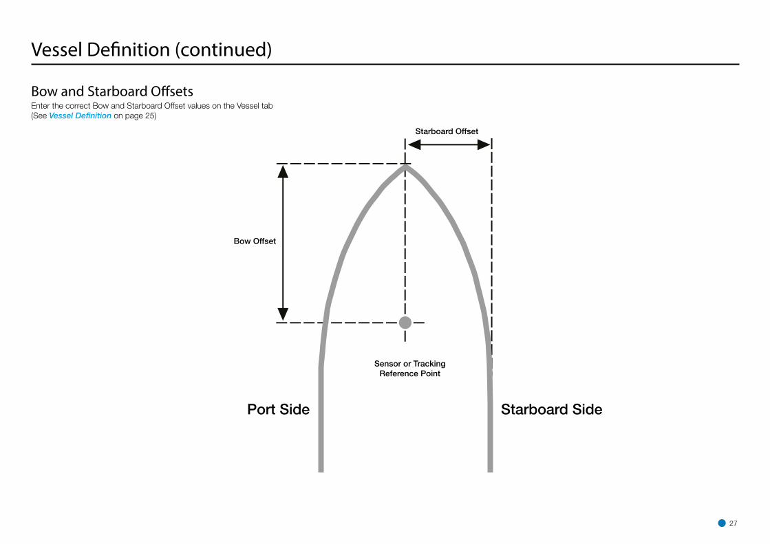
• Bow Offset: Distance from the tracking reference point to the vessel’s bow, in metres.
• Starboard Offset: Distance from the tracking reference point to the vessel’s starboard side, in metres.
• Display Vessel Orientation: The default direction of the vessel bow as displayed on the Dashboard BEV. Changing this setting rotates the whole BEV but does not affect the data sent to the DP system. Note that this setting can be overridden for the current Dashboard session via Advanced > Display Options > Screen Layout, but the BEV reverts to the default orientation when the Dashboard is closed and re-opened.
• Load Vessel Image: Allows the user to upload a vessel image to help validate positioning of sensors / tracking reference point. The image must be PNG format and the bounds of the image must be the same as the bounds of the vessel with the vessel bow at the bottom of the image.
Modifying Vessel Definition
In order to amend any of the above parameters:
1. Click on the Take Command button if the RGSI is not already in command mode.
2. On the Vessel tab, click on the Edit button.
3. Amend the vessel definition as required.
4. Click on Apply to save the changes or on Cancel to discard.
25

Vessel Definition (continued) For the RangeGuard Monopole system to report an accurate position the sensor offsets must be precisely configured. The following fields need to be specified for the two sensors:
Bow Offset: Distance from the centre of the RangeGuard sensor to the vessel’s bow, in metres.
Starboard Offset: Distance from the centre of the RangeGuard sensor to the vessel’s starboard side, in metres.
Bearing Offset: Direction of the sensor relative to the vessel aft, in degrees, increasing in a clockwise direction. See diagram on page 28 for more information.
Range Offset: Offset applied to sensor range measurements, in metres. This should be set to the radius of the monopole structure e.g. for a monopole target with diameter 5.5m users should enter 2.75m for the sensor range offset.
26
Vessel Definition (continued)
Starboard Offset
Bow Offset
Sensor or Tracking Reference Point
Port Side Starboard Side
Bow and Starboard OffsetsEnter the correct Bow and Starboard Offset values on the Vessel tab (See Vessel Definition on page 25)
27

Vessel Definition (continued)
RangeGuard Sensor
Key
Bearing OffsetEnter the correct Bearing Offset value on the Vessel tab (See Vessel Definition on page 25)
Port Approach Configuration
Fore Sensor Bearing Offset = -75°
Aft Sensor Bearing Offset = -105°
Starboard Approach Configuration
Fore Sensor Bearing Offset = 75°
Aft Sensor Bearing Offset = 105°
Field of View
28

The Sensors tab allows users to define the following items for each Sensors:
Enabled: Whether sensor should be powered on. Sensors will be reported as disabled if the “Enabled” check box is un-ticked.
Field of View: Beam width of the sensor, either “Narrow (11°)” or “Wide (110°).” For RangeGuard Monopole applications, both sensors should be “Wide (110°)”.
Mounting Orientation: Whether sensor is mounted upright and sensing in the “Horizontal” plane, or mounted on its side and sensing in the “Vertical” plane. For RangeGuard Monopole applications, both sensors should be “Horizontal”.
!NOTE: Changing the Field Of View / Mounting Orientation has no effect on the physical sensors. It only affects the way the processor handles data from the
sensors. Any mismatch between the actual and configured sensor values will result in invalid target position results being reported.
.
Sensor Definitions
.
29
Blanking Limits
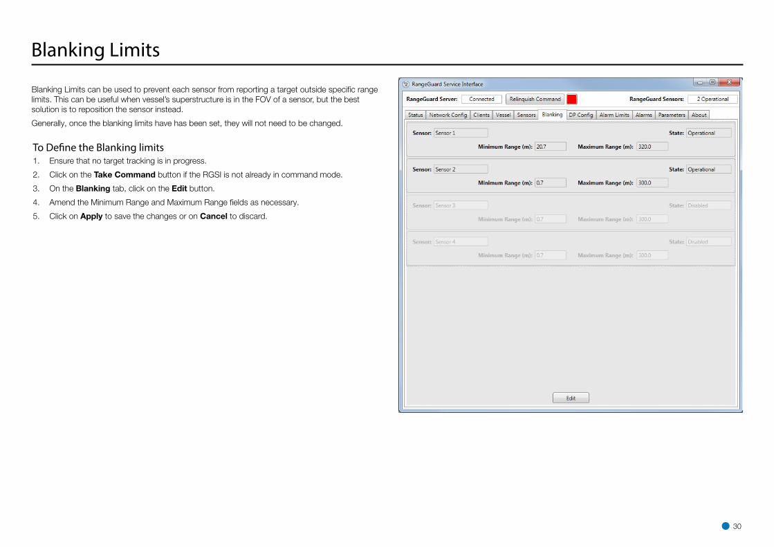
Blanking Limits can be used to prevent each sensor from reporting a target outside specific range limits. This can be useful when vessel’s superstructure is in the FOV of a sensor, but the best solution is to reposition the sensor instead.
Generally, once the blanking limits have has been set, they will not need to be changed.
To Define the Blanking limits1. Ensure that no target tracking is in progress.
2. Click on the Take Command button if the RGSI is not already in command mode.
3. On the Blanking tab, click on the Edit button.
4. Amend the Minimum Range and Maximum Range fields as necessary.
5. Click on Apply to save the changes or on Cancel to discard.
30
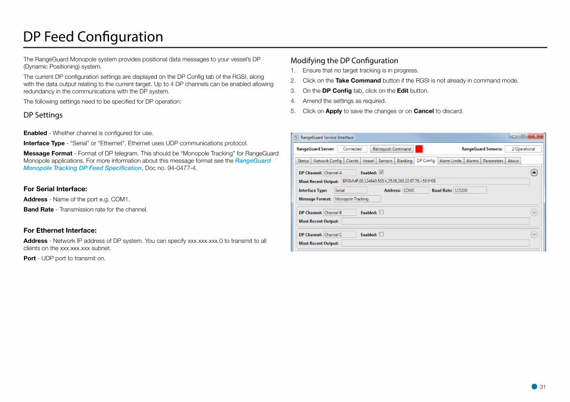
DP Feed ConfigurationThe RangeGuard Monopole system provides positional data messages to your vessel’s DP (Dynamic Positioning) system.
The current DP configuration settings are displayed on the DP Config tab of the RGSI, along with the data output relating to the current target. Up to 4 DP channels can be enabled allowing redundancy in the communications with the DP system.
The following settings need to be specified for DP operation:
DP Settings
Enabled - Whether channel is configured for use.
Interface Type - “Serial” or “Ethernet”. Ethernet uses UDP communications protocol.
Message Format - Format of DP telegram. This should be “Monopole Tracking” for RangeGuard Monopole applications. For more information about this message format see the RangeGuard Monopole Tracking DP Feed Specification, Doc no. 94-0477-4.
For Serial Interface:
Address - Name of the port e.g. COM1.
Band Rate - Transmission rate for the channel.
For Ethernet Interface:
Address - Network IP address of DP system. You can specify xxx.xxx.xxx.0 to transmit to all clients on the xxx.xxx.xxx subnet.
Port - UDP port to transmit on.
Modifying the DP Configuration1. Ensure that no target tracking is in progress.
2. Click on the Take Command button if the RGSI is not already in command mode.
3. On the DP Config tab, click on the Edit button.
4. Amend the settings as required.
5. Click on Apply to save the changes or on Cancel to discard.
31
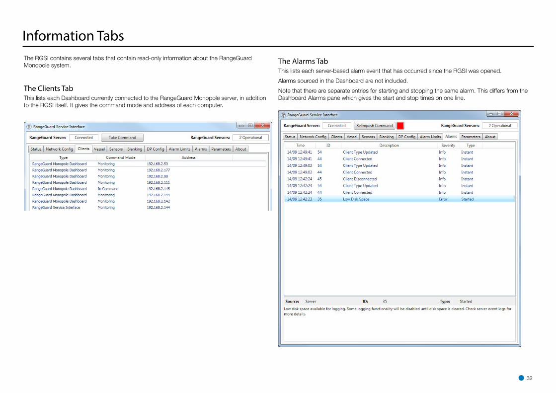
Information TabsThe RGSI contains several tabs that contain read-only information about the RangeGuard Monopole system.
The Clients TabThis lists each Dashboard currently connected to the RangeGuard Monopole server, in addition to the RGSI itself. It gives the command mode and address of each computer.
The Alarms TabThis lists each server-based alarm event that has occurred since the RGSI was opened.
Alarms sourced in the Dashboard are not included.
Note that there are separate entries for starting and stopping the same alarm. This differs from the Dashboard Alarms pane which gives the start and stop times on one line.
32

Information Tabs (continued)The About TabThis contains Version information for the RGSI and server, the serial number of the server, contact details for Guidance Marine Ltd and a button for opening an on-screen copy of this Installer’s Guide.
33

This section contains the following appendices:
• International Standards Compliance (page 35)
• Part Numbers (page 36)
• UPS and Cable Specifications (page 37)
• Installation Checklist (page 38)
• Index (page 40)
Appendices
34
International Standards Compliance
RangeGuard System
European UnionThe equipment is permitted to be used in all EU member states without the need for a specific administrative licence.
The RangeGuard K-Band Sensor meets the R&TTE Directive.
The equipment complies with EN 60945:2002.
USAUse of the RangeGuard system in the United States of America is authorised by the Federal Communications Commission. FCC ID: VYMRangeGuard.
35

Processing Unit
Component Part Number
Monopole DP Processing Unit 20-0237
SensorComponent Part Number
RangeGuard Sensor 20-0183-1
Guidance Marine System Level USB 180-0011-4
Operator’s Guide 94-0522-4
Installer’s Guide 94-0523-4
Marine ProcessorComponent Part Number
Type 3 Marine Processor 20-0234
Hatteland Panel PC 20-0182-1
Hatteland VESA Bracket 24-0258-4
Hatteland Mounting Bracket 24-0259-4
Hatteland 15” Monitor Mounting Bracket 94-0523-4
CablesComponent Part Number
Power Cable (40m) 33-0121-3
Data Cable (40m) 33-0451-3
Ethernet Cable (40m) 33-0124-3
RangeGuard to Processing Unit Interface Cable (50m) 33-0469-4
Ethernet Connector Plug 80-0075-4
Lanyard Assembly 24-0306-0
Part Numbers
36

UPS and Cable Specifications
UPS SpecificationsIt is recommended that the main power supply to the RangeGuard Monopole System comes directly from an Uninterruptible Power Supply (UPS).
RangeGuard Processing Unit with up to 4 Sensors
• Voltage Range = 85-264 VAC
• Frequency Range = 50-60Hz
• Nominal Power with 4 sensors = 30W
Type 3 Marine Processor Power Adaptor
• Voltage Range = 100-240V
• Frequency Range = 50-60Hz
• Peak Current draw = 1.8A RMS
Hatteland Panel PC
• Voltage Range = 115 & 230V
• Frequency Range = 50-60Hz
• Nominal Power = 60W
Processing Unit DP Feed Output
1 2 3 4 56 7 8 9
RX+ TX- GND
DP System
Type 3 Marine Processor
COM1..COM4
RS422 Link9600 baud8 bits1 stop bitNo parity TX
+
TX-
GN
D
37
Cable SpecificationsThe signal cables from the controller to the sensors carry power, analogue control and data signals.
The sensor cabling is connected as shown below using standard CAT5 or CAT6 screened cable. The cable shield must be connected from the sensor to the control box. Screened RJ45 plugs must be used.
The maximum length of cable for any sensor cable is 100m.
The cable should be shielded flexible multi strand twisted pair cable (Cat5e or similar) with a minimum wire gauge of 24AWG (smaller AWG number is thicker gauge).
!Note: Incorrect wiring may cause damage to the sensor and invalidate warranty.
Sensor Cable Wiring Description
Wire Amphenol RJ45
Orange / White A 1
Orange + Screen (Amphenol) B 2
Green / White C 3
Blue D 4
Blue / White E 5
Green F 6
Brown / White G 7
Brown J 8
The RangeGuard system is usually supplied without the cables that are necessary to connect the sensor to the DP system and the client software computer(s). Cables must be supplied and fitted by the installer to match the particular requirements for the vessel. Guidance Marine recommends that flexible multicore cables are used in all applications. Cables should meet the requirements of IEC 60228 Class 2 or Class 5.
!Note: Data cables should not be run across or next to power cables to avoid signal interference problems.

38
RangeGuard Sensor Serial No.s
RangeGuard Processing Unit Serial No.
Marine Processor Serial No.
RangeGuard Processing Unit IP Address.
Shipping Line
Vessel Name
Installer
Mechanical InstallationCheck Requirement Sensors The sensors are securely mounted.
The sensors are facing the required direction.
There are no obvious obstacles in the sensors field of view.
Cables The cables are suitably secured.
Computer and control unit
The computer and control unit is mounted securely.
Processing Unit ConnectionsCheck Requirement General All cable shields are correctly connected.
Power The computer and control box are connected to the mains power supply (preferably a UPS).
The power supply voltage is within the required range.
Sensors All of the sensors are connected to the control box.
DP Feed The DP feed – if required – is connected to the DP system.
Network The computer is connected to an appropriate network.
RGSI/Dashboard ConfigurationCheck Requirement Dashboard record of Server IP Address
The Dashboard has a correct record of the server’s network IP address. This can be checked by navigating to Advanced > Comms Settings.
Dashboard Date and Time
The Marine Processor’s Date and Time are set correctly.
ID / Version Info The Server’s serial number is shown correctly.
The Server and Dashboard software version details are correct.
Communications /Display Options
The DP Message Formats are set correctly for the vessel’s DP system.
The Bow Orientation is set correctly.
If the Marine Processor does not have a physical keyboard, the on-screen keyboard is enabled.
Logging functions correctly.
Vessel Parameters The Vessel Dimensions have been entered correctly.
The Bow and Starboard Offsets have been set correctly.
Sensor Parameters The sensors have sensible names e.g. Fore Sensor, Aft Sensor.
The sensors are wide beam mounted horizontally.
The sensor positions (bow, starboard and bearing offsets) are correctly configured
The sensor range offsets are correctly configured for the size of monopole target.
Blanking Limits Blanking limits have been set to exclude any superstructure in the FOV of the sensor.
Disk Space There is enough free space to accommodate Dashboard data logging.
PDF Reader Click on the F1 button and check that the RangeGuard Operator’s Guide can be viewed. If not, ensure that a PDF reader is installed.
Alarms No Warning, Error or Fatal alarms have been raised by the system.
Installation Checklist

39
Network Connection TestsCheck Requirement Server –Dashboard Connection
The network connection between the Server and the Dashboard is OK.
Server –DP Connection
The DP system can receive a message string from the Server.
Sensor –Server Connection
The server reports two operational sensors.
Functional Tests
Check Requirement System is Operational
A target can be identified by the system.
Range Test The system is able to locate a target at a distance no less than 50 metres.
DP System Test The RangeGuard Monopole system’s DP feed message is accepted by the DP system.
The DP weighting against other available reference systems is within acceptable levels.
TrainingCheck Requirement Basic Operation The crew understand the basic operation of the system.
The crew understand the need to switch on the system early.
The crew know that RangeGuard Monopole system is only for use against monopole targets.
Operator’s Guide The crew know how to access the Operator’s Guide.
Installation Checklist (Continued)

Configuration 12, 28 Guidelines 11 Offsets 11 Sensor 11, 12, Template 15
NNarrow Beam 29Network Config Tab 23, 24
OOffset Bearing 28 Bow 27 Starboard 27Operating Region 12Operating Range 12Overview System 7
PPart Numbers 36Power Output 37Positioning Sensors 11, 12, 27, 28Processing Unit Connections 38 Dimensions 14 Hardware 14, 37 Label 9 Mounting 11 Power 38 Software 18Product Labels 9
AAbout System Pane 8About Tab 33Alarm Limits TabAlarms Tab 32Applications and Vessel Types 11
BBearing Offset 26, 28Blanking Tab 30Bow Offset 25, 26, 27
CCable Routing Diagram 16, 17 Cable Specifications 37Client Software Overview 7 Installation 20Clients Tab 32
DDashboard Software About System Pane 8Data Cable 16, 36Default IP Address 23Dimensions Sensor 13 Processing Unit 14 Marine Processor 14 Vessel 25Document History 3DP Config Tab 31DP Message Types 31
EEthernet Connector plug 36 Cable 16, 17, 31, Link 16, 17, 31, 36European Union 35
FField of View 7, 11, 12, 28, 29FCC 2, 35
HHardware 10Hatteland Marine Touchscreen 17 Mounting Brackets 36 Panel PC 17, 19, 36, 37
IInstallation Processing Unit Hardware Sensor Hardware 10 Client Software 20 Server Software 2, 18 Checklist 38International Standards Compliance 35IP Address 2, 18, 20, 23, 24, 31
LLabels 9Lanyard Fixing Point 13
MMounting
Index
40
RRange Offset 26, 38Reference Point 12, 25, 27RS422 37
SSensor Connections 16 Dimensions 13, 14, 15 Hardware 10 Label 9 Mounting 11, 12 Power 37Sensors Tab 29Serial Numbers 8Server Software Installation 18Service Interface software About Tab 33 Alarms Tab 32 Blanking Tab 30 Clients Tab 32 DP Config Tab 31 Network Config Tab 23, 24 Sensors Tab 29 Status Tab 22 Vessel Tab 25, 27, 28Software Versions 8Specifications Cable 37 UPS 37Standards 35Starboard Offset 25, 26, 27, 38Status Tab 22
Status Indicators 22System Overview 7System Operating Region Field of View 12 Port or Starboard 28 Range Limits 30
TTracking Reference Point 25, 27Type 3 Marine Processor 7, 17, 20, 36, 37
UUPS 16, 37, 38USA 2, 35
VVertical Beam Height 7, 11Vessel Definition 25, 26, 27, 28Vessel Tab 25, 27, 28Vessel Image 25
WWide Beam 38Wiring 37
Index (continued)
41

Related Documents