Grid-Connected PV Systems: Design and Installation 8 Page | 167 © 2020 GSES Chapter 9: Balance of System Equipment 9.1 Cabling Grid-connected PV systems require both DC and AC cabling to connect the relevant characteristics of their respective form of electricity and should not be interchanged. The DC cables found in a grid-connected PV system are ( ): • PV module cables: These are typically pre-connected to the module and connect a set of PV modules in series, forming a string. • PV string cables: These connect a string of modules to the PV string combiner box. • PV sub-array cables: In larger systems, these connect the PV string combiner box to the PV array combiner box. • PV array cables: These connect the PV string combiner box (or the PV array combiner box in larger systems) to the PV array DC disconnectors. • Inverter DC cables: These connect the PV array DC disconnectors to the DC side of the inverter. This cabling may also be referred to as PV array cabling, but it has been separated in this publication to provide an extra description. The AC cables ( ) found in a grid-connected PV system are AC supply cables. These connect the inverter to the inverter AC disconnector (at the inverter, if necessary) and then to the point of connection to the grid (the PV array main switch) in the switchboard. The array’s earthing cables are also an important part of a grid-connected PV system. They are needed to protect both the system equipment and people from dangerous fault conditions, and may be required for the operation of some systems. As earthing is part of a system’s protection, it is covered in . Details of how to correctly select and size the cables in a grid-connected PV system are covered in . 9.1.1 DC Cables DC cables are used between the PV modules and the DC side of the inverter. It is important to ensure that the DC cabling used is correctly labelled in accordance with applicable standards. Module Cables Modules usually come with a positive and a negative cable hardwired into the module’s junction box at the back of the module. These are used to connect the modules together to form a string. Each pairing of cables has a male and a female connector (or ‘plug’) to wire modules together quickly and safely (see interconnections section below). The cable and plugs can also be individually purchased so that the module cable lengths can be adjusted to suit a particular installation. Module cable sizes are typically 4 mm 2 . String, Sub-Array, Array and Inverter DC Cables String cables connect the strings of modules to the PV string combiner box. In larger systems, sub-array cables are used to connect the PV string combiner box to the PV array combiner box. Array cables are used to connect the PV string combiner box (or the PV array combiner box in larger systems) to the PV array DC disconnectors. Finally, DC cables are used between the PV array DC disconnectors and the inverter. AUSTRALIAN STANDARDS Clause 4.3.7 states that: • All connector pairings must be of the same type and from the same manufacturer • Cables used within the PV array shall be: • UV-resistant (if exposed to the environment) • Rated to the overcurrent protection device, or maximum normal operating current • Flexible, to allow for movement of the cable • Single core, double insulated. According to AS/NZS 5033:2014, all cables used for the PV array must meet PV1-F requirements, UL 4703, or VDE-AR-E 2283-4.

Welcome message from author
This document is posted to help you gain knowledge. Please leave a comment to let me know what you think about it! Share it to your friends and learn new things together.
Transcript
Grid-Connected PV Systems: Design and Installation 8
Page | 167© 2020 GSES Chapter 9: Balance of System Equipment
9.1 CablingGrid-connected PV systems require both DC and AC cabling to connect the relevant
characteristics of their respective form of electricity and should not be interchanged.The DC cables found in a grid-connected PV system are ( ):
• PV module cables: These are typically pre-connected to the module and connect a set of PV modules in series, forming a string.
• PV string cables: These connect a string of modules to the PV string combiner box.
• PV sub-array cables: In larger systems, these connect the PV string combiner box to the PV array combiner box.
• PV array cables: These connect the PV string combiner box (or the PV array combiner box in larger systems) to the PV array DC disconnectors.
• Inverter DC cables: These connect the PV array DC disconnectors to the DC side of the inverter. This cabling may also be referred to as PV array cabling, but it has been separated in this publication to provide an extra description.
The AC cables ( ) found in a grid-connected PV system are AC supply cables. These connect the inverter to the inverter AC disconnector (at the inverter, if necessary) and then to the point of connection to the grid (the PV array main switch) in the switchboard.
The array’s earthing cables are also an important part of a grid-connected PV system. They are needed to protect both the system equipment and people from dangerous fault conditions, and may be required for the operation of some systems. As earthing is part of a system’s protection, it is covered in .
Details of how to correctly select and size the cables in a grid-connected PV system are covered in .
9.1.1 DC CablesDC cables are used between the PV modules and the DC side of the inverter.
It is important to ensure that the DC cabling used is correctly labelled in accordance with applicable standards.
Module CablesModules usually come with a positive and a negative cable hardwired into the module’s junction box at the back of the module. These are used to connect the modules together to form a string. Each pairing of cables has a male and a female connector (or ‘plug’) to wire modules together quickly and safely (see interconnections section below). The cable and plugs can also be individually purchased so that the module cable lengths can be adjusted to suit a particular installation. Module cable sizes are typically 4 mm2.
String, Sub-Array, Array and Inverter DC CablesString cables connect the strings of modules to the PV string combiner box. In larger systems, sub-array cables are used to connect the PV string combiner box to the PV array combiner box. Array cables are used to connect the PV string combiner box (or the PV array combiner box in larger systems) to the PV array DC disconnectors. Finally, DC cables are used between the PV array DC disconnectors and the inverter.
AUSTRALIAN STANDARDS Clause 4.3.7
states that:• All connector pairings must be of
the same type and from the same manufacturer
• Cables used within the PV array shall be:
• UV-resistant (if exposed to the environment)
• Rated to the overcurrent protection device, or maximum normal operating current
• Flexible, to allow for movement of the cable
• Single core, double insulated.
According to AS/NZS 5033:2014, all cables used for the PV array must meet PV1-F requirements, UL 4703, or VDE-AR-E 2283-4.
Grid-Connected PV Systems: Design and Installation 8
Page | 281© 2020 GSES Chapter 13: System Protection
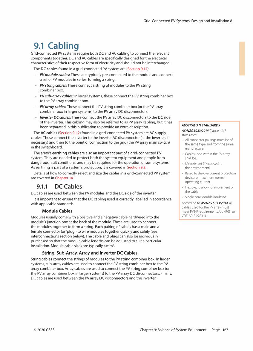
13.3 DC Disconnection DevicesDisconnection devices allow parts of the system to be electrically isolated. DC disconnection devices can be split into two categories:
1. through them; these devices are switch-disconnectors or circuit breakers, although the term ‘isolators’ is used for simplicity in labelling.
2. Non-load-breaking, where they can be disconnected only when there is no
Disconnection devices may be required at the string, sub-array and/or array level of a grid-connected PV system. For all levels of disconnection, the device used should have no live parts exposed at any time, regardless of whether the device is switched
standards and guidelines.The disconnection device may be combined with the overcurrent protection in the
form of a DC circuit breaker. If this is done, a suitable circuit breaker must be selected. According to the latest standards, circuit breakers must be non-polarised. It can be advantageous to install a non-polarised circuit breaker (or other appropriate easy to
13.3.1 String DisconnectionString disconnection enables each string of the PV array to be electrically isolated from the other strings and the rest of the PV system.
Requirements of String Disconnection DevicesFor both LV (120–1,500 V DC) and ELV (<120 V DC) systems, it is recommended that the string cable has a form of non-load-breaking disconnection.
Sizing the String Disconnection DevicesThe required sizing of string disconnection devices is as follows:
• Rated for PV array maximum voltage.• Have a current rating greater than or equal to the string overcurrent
protection present. If a string overcurrent protection device is not present, the disconnection device must have a minimum rating of the CCC of the string cable.
Installation of String Disconnection DevicesNon-load-breaking disconnection is usually provided by module manufacturers in the form of plug-and-socket connectors. If circuit breakers are used as the overcurrent protection and means of disconnection, these would be installed in the string combiner box.
AUSTRALIAN STANDARDS Clause 1.4.13
Clause 4.3.5 covers the requirements for DC disconnection devices.
states that load-breaking switches should be lockable
IMPORTANT!Disconnection devices do not
Circuit breakers can be used to provide overcurrent protection and disconnection, so that they switch
If separate overcurrent protection is present, the disconnection device must have the same current rating: otherwise it may be damaged by overcurrent.
AUSTRALIAN STANDARDSAccording to AS/NZS 5033:2014 Clause 4.2, the PV array maximum voltage is calculated using:VMAX_OC_ARRAY = VOC_ARRAY + γOC × (TMIN − TSTC) × NS
Where:• V
MAX_OC_ARRAY = PV array maximum
voltage (in V)
• VOC_ARRAY = PV array open circuit voltage at standard test conditions (in V)
• γOC
= Negative temperature VOC per degree Celsius
(in V/°C)
• TMIN
= Minimum cell temperature (in °C)
• TSTC
= Cell temperature at standard test conditions (constant of 25°C)
• NS = Number of modules in series
is not available, AS/NZS 5033:2014 Table 4.1 contains some universal
EXAMPLEAn array has 12 modules set up in two parallel strings of 6 modules, with VOC of 39.2 V, γVOC of –0.33%/°C and ISC of 7.4 A. Calculate the PV array maximum voltage for this array, given that the site’s lowest expected temperature is 5°C.
Since there are 6 modules in each string and voltage is the same in parallel strings, the PV array maximum voltage is:
VMAX_OC_ARRAY = VOC_ARRAY + γOC × (TMIN − TSTC ) × NS
= (39.2 V × 6) + (− 0.0033/°C × 39.2 V) × (5°C − 25°C)] × 6
= 250.7 V= 235.2 V + 0.1294 V/°C × 20°C × 6
Page | 282 PART III: Design and Installation
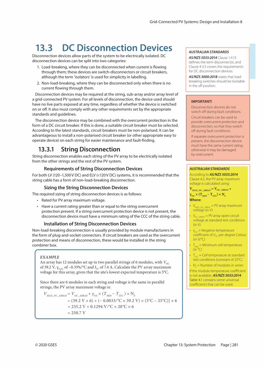
13.3.2 Sub-array DisconnectionSub-array disconnection enables each sub-array of the PV array to be electrically isolated from the other sub-arrays and the rest of the PV system.
Requirements of Sub-array Disconnection DevicesFor LV and ELV systems, each sub-array cable is required to have a disconnection device for isolation. This device does not have to be load-breaking. Systems with sub-arrays are generally large: a load-breaking disconnection device could be advantageous as an additional safety feature for large, LV systems. Should a load-breaking disconnection device be chosen, it must be non-polarised and able to isolate all active conductors simultaneously.
Sizing the Sub-array Disconnection DevicesSizing of the sub-array disconnection devices is required to be as follows:
• Rated for PV array maximum voltage.• Have a current rating greater than or equal to the sub-array overcurrent
protection present. If a sub-array overcurrent protection device is not present, the disconnection device must have a minimum rating of the CCC of the sub-array cable.
Installation of Sub-array Disconnection DevicesThe module’s plug–and-socket connectors will act as the non-load-breaking disconnection of sub-arrays. If circuit breakers are used as the overcurrent protection and means of disconnection, these would be installed in the string combiner box.
13.3.3 Array DC DisconnectionA load-breaking device for disconnecting the PV array on the DC side of the inverter is essential for safety in grid-connected PV systems. Two DC disconnectors may be required: one adjacent to the array and one adjacent to the inverter (see ‘Installation of Array DC Disconnectors’ below).
Requirements of PV Array DC DisconnectorsFor all systems, the PV array DC isolators must be readily available load-breaking
and able to isolate both positive and negative active conductors simultaneously under load.
A non-polarised circuit breaker can be used as the readily available load-breaking disconnection device.
If micro-inverters are used, an array DC disconnector may not be required. The relevant standards should always be referenced when determining disconnector requirements.
AUSTRALIAN STANDARDSAS/NZS 5033:2014 Clause 4.3.12 outlines installation requirements applicable to micro-inverters.
Page | 283Chapter 13: System Protection
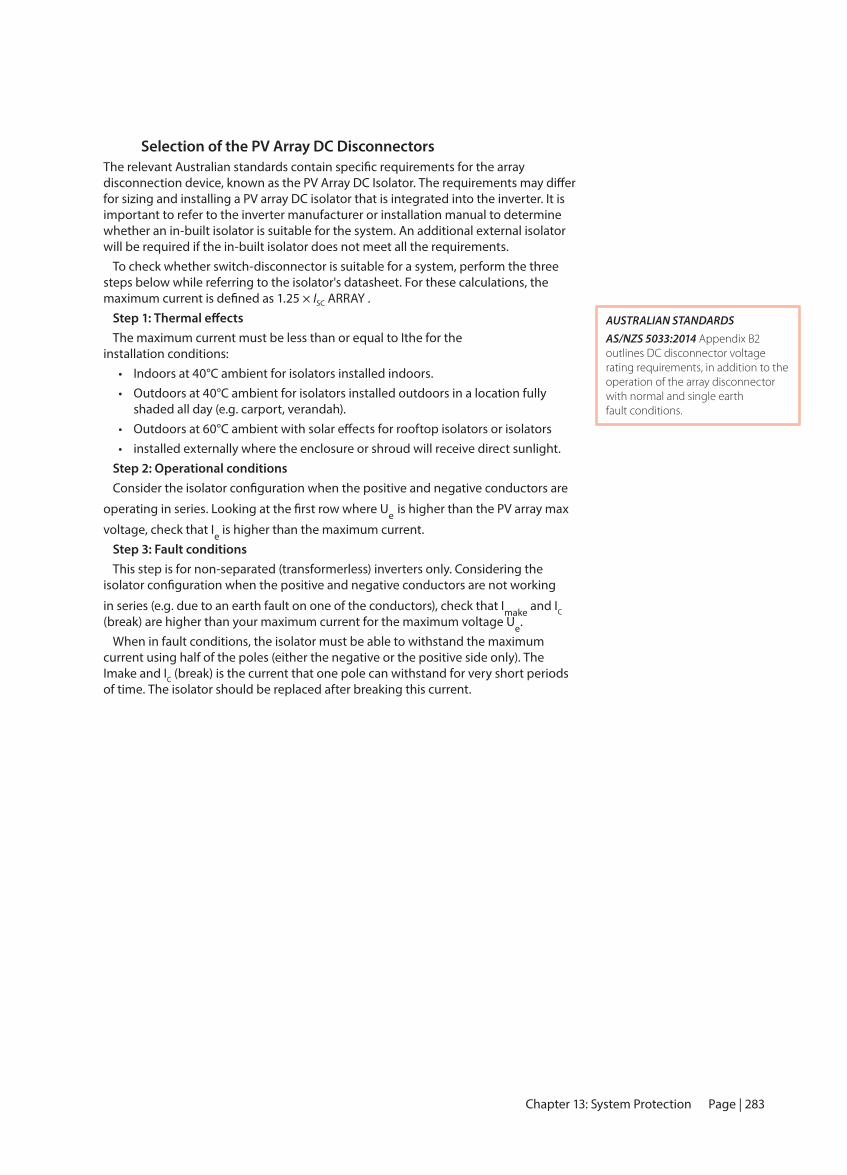
Selection of the PV Array DC Disconnectors
for sizing and installing a PV array DC isolator that is integrated into the inverter. It is important to refer to the inverter manufacturer or installation manual to determine whether an in-built isolator is suitable for the system. An additional external isolator will be required if the in-built isolator does not meet all the requirements.
To check whether switch-disconnector is suitable for a system, perform the three steps below while referring to the isolator's datasheet. For these calculations, the
ISC ARRAY .
The maximum current must be less than or equal to Ithe for the installation conditions:
• Indoors at 40°C ambient for isolators installed indoors.• Outdoors at 40°C ambient for isolators installed outdoors in a location fully
shaded all day (e.g. carport, verandah).• • installed externally where the enclosure or shroud will receive direct sunlight.
Step 2: Operational conditions
e is higher than the PV array max
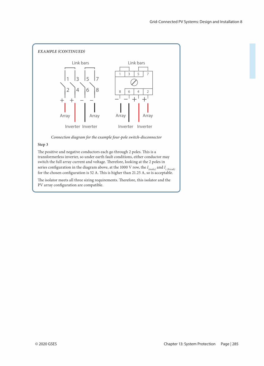
voltage, check that Ie is higher than the maximum current.Step 3: Fault conditionsThis step is for non-separated (transformerless) inverters only. Considering the
in series (e.g. due to an earth fault on one of the conductors), check that Imake and IC (break) are higher than your maximum current for the maximum voltage Ue.
When in fault conditions, the isolator must be able to withstand the maximum current using half of the poles (either the negative or the positive side only). The Imake and IC (break) is the current that one pole can withstand for very short periods of time. The isolator should be replaced after breaking this current.
AUSTRALIAN STANDARDSAS/NZS 5033:2014 Appendix B2 outlines DC disconnector voltage rating requirements, in addition to the operation of the array disconnector with normal and single earth fault conditions.
Grid-Connected PV Systems: Design and Installation 8
Page | 284 © 2020 GSESPART III: Design and Installation
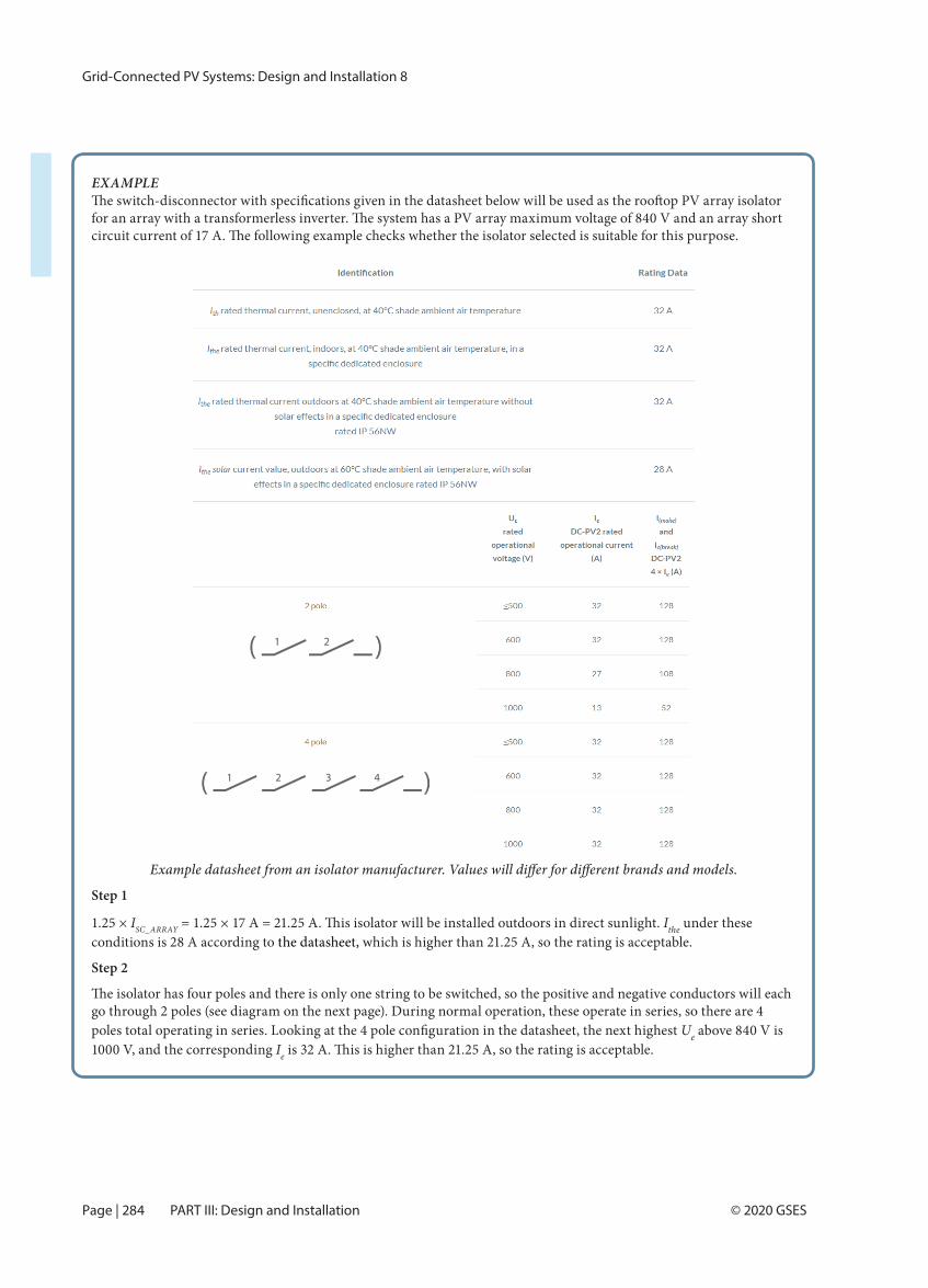
EXAMPLE
Step 1
1.25 × ISC_ARRAY Ithe under these conditions is 28 A according to the datasheet, which is higher than 21.25 A, so the rating is acceptable.
Step 2
go through 2 poles (see diagram on the next page). During normal operation, these operate in series, so there are 4 Ue above 840 V is
1000 V, and the corresponding Ie
Grid-Connected PV Systems: Design and Installation 8
Page | 286 © 2020 GSESPART III: Design and Installation
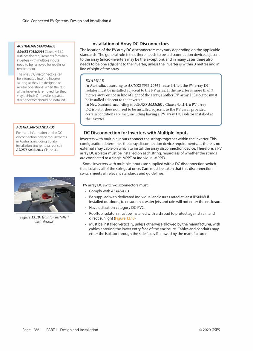
Installation of Array DC DisconnectorsThe location of the PV array DC disconnectors may vary depending on the applicable standards. The general rule is that there needs to be a disconnection device adjacent to the array (micro-inverters may be the exception), and in many cases there also needs to be one adjacent to the inverter, unless the inverter is within 3 metres and in line of sight of the array.
DC Disconnection for Inverters with Multiple InputsInverters with multiple inputs connect the strings together within the inverter. This
external array cable on which to install the array disconnection device. Therefore, a PV array DC isolator must be installed on each string, regardless of whether the strings are connected to a single MPPT or individual MPPTs.
Some inverters with multiple inputs are supplied with a DC disconnection switch that isolates all of the strings at once. Care must be taken that this disconnection switch meets all relevant standards and guidelines.
PV array DC switch-disconnectors must:• Comply with AS 60947.3• Be supplied with dedicated individual enclosures rated at least IP56NW if
installed outdoors, to ensure that water jets and rain will not enter the enclosure.• Have utilization category DC-PV2.• Rooftop isolators must be installed with a shroud to protect against rain and
direct sunlight (Figure 13.10)• Must be installed vertically, unless otherwise allowed by the manufacturer, with
cables entering the lower entry face of the enclosure. Cables and conduits may enter the isolator through the side faces if allowed by the manufacturer.
EXAMPLEIn Australia, according to AS/NZS 5033:2014 Clause 4.4.1.4, the PV array DC isolator must be installed adjacent to the PV array. If the inverter is more than 3 metres away or not in line of sight of the array, another PV array DC isolator must be installed adjacent to the inverter.In New Zealand, according to AS/NZS 5033:2014 Clause 4.4.1.4, a PV array DC isolator does not need to be installed adjacent to the PV array provided certain conditions are met, including having a PV array DC isolator installed at the inverter.
AUSTRALIAN STANDARDSAS/NZS 5033:2014 Clause 4.4.1.2 outlines the requirements for when inverters with multiple inputs need to be removed for repairs or replacement.
The array DC disconnectors can be integrated into the inverter as long as they are designed to remain operational when the rest of the inverter is removed (i.e. they stay behind). Otherwise, separate disconnectors should be installed.
AUSTRALIAN STANDARDSFor more information on the DC disconnection device requirements in Australia, including isolator installation and removal, consult AS/NZS 5033:2014 Clause 4.4.
Figure 13.10: Isolator installed with shroud.
Grid-Connected PV Systems: Design and Installation 8
Page | 285© 2020 GSES Chapter 13: System Protection
Connection diagram for the example four-pole switch-disconnector
Step 3
transformerless inverter, so under earth fault conditions, either conductor may
I(make) and Ic (break)
6 8
5 7
2 4
1 3
+ +
Link bars
Array
Inverter Inverter
– –
Array
++
1 3 5 7
2468 ––
Link bars
Array
Inverter Inverter
Array
Grid-Connected PV Systems: Design and Installation 8
Page | 287© 2020 GSES Chapter 13: System Protection
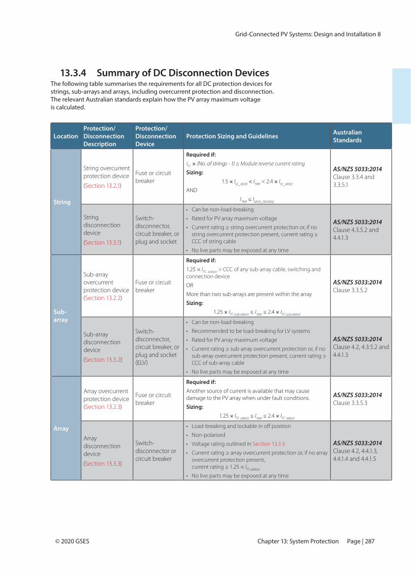
13.3.4 Summary of DC Disconnection DevicesThe following table summarises the requirements for all DC protection devices for strings, sub-arrays and arrays, including overcurrent protection and disconnection. The relevant Australian standards explain how the PV array maximum voltage is calculated.
LocationProtection/Disconnection Description
Protection/Disconnection Device
Protection Sizing and Guidelines Australian Standards
String
String overcurrent protection device
(Section 13.2.1)
Fuse or circuit breaker
Required if:ISC × (No. of strings - 1) ≥ Module reverse current rating
Sizing:1.5 × ISC_MOD < ITRIP < 2.4 × ISC_MOD
AND
ITRIP ≤ IMOD_REVERSE
AS/NZS 5033:2014 Clause 3.3.4 and 3.3.5.1
String disconnection device
(Section 13.3.1)
Switch-disconnector, circuit breaker, or plug and socket
• Can be non-load-breaking
• Rated for PV array maximum voltage
• Current rating ≥ string overcurrent protection or, if no string overcurrent protection present, current rating ≥ CCC of string cable
• No live parts may be exposed at any time
AS/NZS 5033:2014 Clause 4.3.5.2 and 4.4.1.3
Sub-array
Sub-array overcurrent protection device (Section 13.2.2)
Fuse or circuit breaker
Required if:1.25 × ISC
ARRAY > CCC of any sub-array cable, switching and
connection device
OR
More than two sub-arrays are present within the array
Sizing:1.25 × ISC SUB-ARRAY ≤ ITRIP ≤ 2.4 × ISC SUB-ARRAY
AS/NZS 5033:2014 Clause 3.3.5.2
Sub-array disconnection device
(Section 13.3.2)
Switch-disconnector, circuit breaker, or plug and socket (ELV)
• Can be non-load-breaking
• Recommended to be load-breaking for LV systems
• Rated for PV array maximum voltage
• Current rating ≥ sub-array overcurrent protection or, if no sub-array overcurrent protection present, current rating ≥ CCC of sub-array cable
• No live parts may be exposed at any time
AS/NZS 5033:2014 Clause 4.2, 4.3.5.2 and 4.4.1.3
Array
Array overcurrent protection device (Section 13.2.3)
Fuse or circuit breaker
Required if:Another source of current is available that may cause damage to the PV array when under fault conditions.
Sizing:1.25 × ISC ARRAY ≤ ITRIP ≤ 2.4 × ISC ARRAY
AS/NZS 5033:2014 Clause 3.3.5.3
Array disconnection device
(Section 13.3.3)
Switch-disconnector or circuit breaker
•
• Non-polarised
• Voltage rating outlined in Section 13.3.3
• Current rating ≥ array overcurrent protection or, if no array overcurrent protection present, current rating ≥ 1.25 × ISC-ARRAY
• No live parts may be exposed at any time
AS/NZS 5033:2014 Clause 4.2, 4.4.1.3, 4.4.1.4 and 4.4.1.5
Grid-Connected PV Systems: Design and Installation 8
Page | 293© 2020 GSES Chapter 13: System Protection
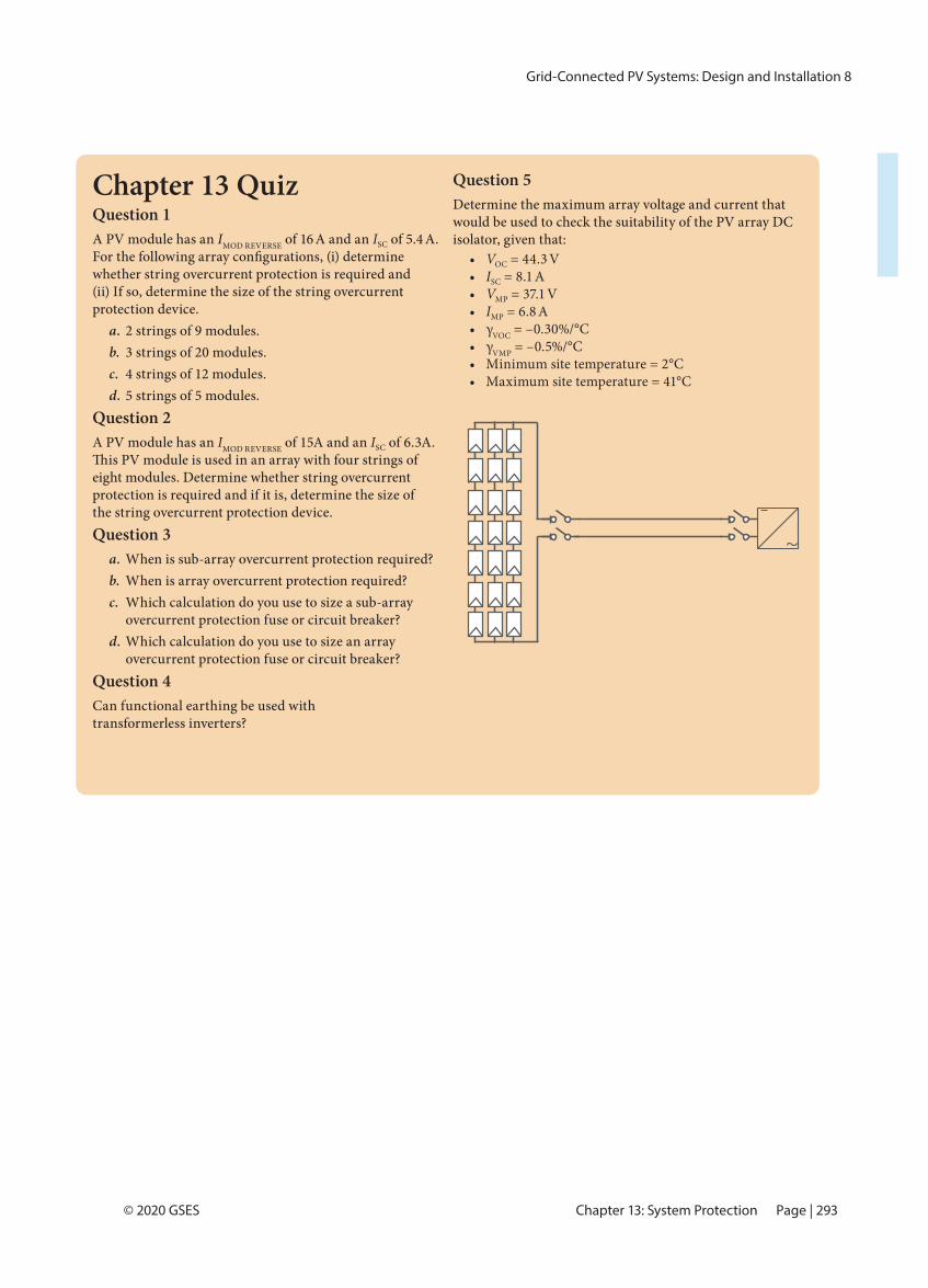
Chapter 13 QuizQuestion 1A PV module has an IMOD REVERSE of 16 A and an ISC of 5.4 A.
whether string overcurrent protection is required and (ii) If so, determine the size of the string overcurrent protection device.
a. 2 strings of 9 modules.b. 3 strings of 20 modules.c. 4 strings of 12 modules.d. 5 strings of 5 modules.
Question 2A PV module has an IMOD REVERSE of 15A and an ISC of 6.3A.
eight modules. Determine whether string overcurrent protection is required and if it is, determine the size of the string overcurrent protection device.Question 3
a. When is sub-array overcurrent protection required?b. When is array overcurrent protection required?c. Which calculation do you use to size a sub-array
overcurrent protection fuse or circuit breaker?d. Which calculation do you use to size an array
overcurrent protection fuse or circuit breaker?Question 4Can functional earthing be used with transformerless inverters?
Question 5Determine the maximum array voltage and current that would be used to check the suitability of the PV array DC isolator, given that:
• VOC = 44.3 V• ISC = 8.1 A• VMP = 37.1 V• IMP = 6.8 A• γVOC = –0.30%/°C• γVMP = –0.5%/°C• Minimum site temperature = 2°C• Maximum site temperature = 41°C
Grid-Connected PV Systems: Design and Installation 8
Page | 298 © 2020 GSESPART III: Design and Installation
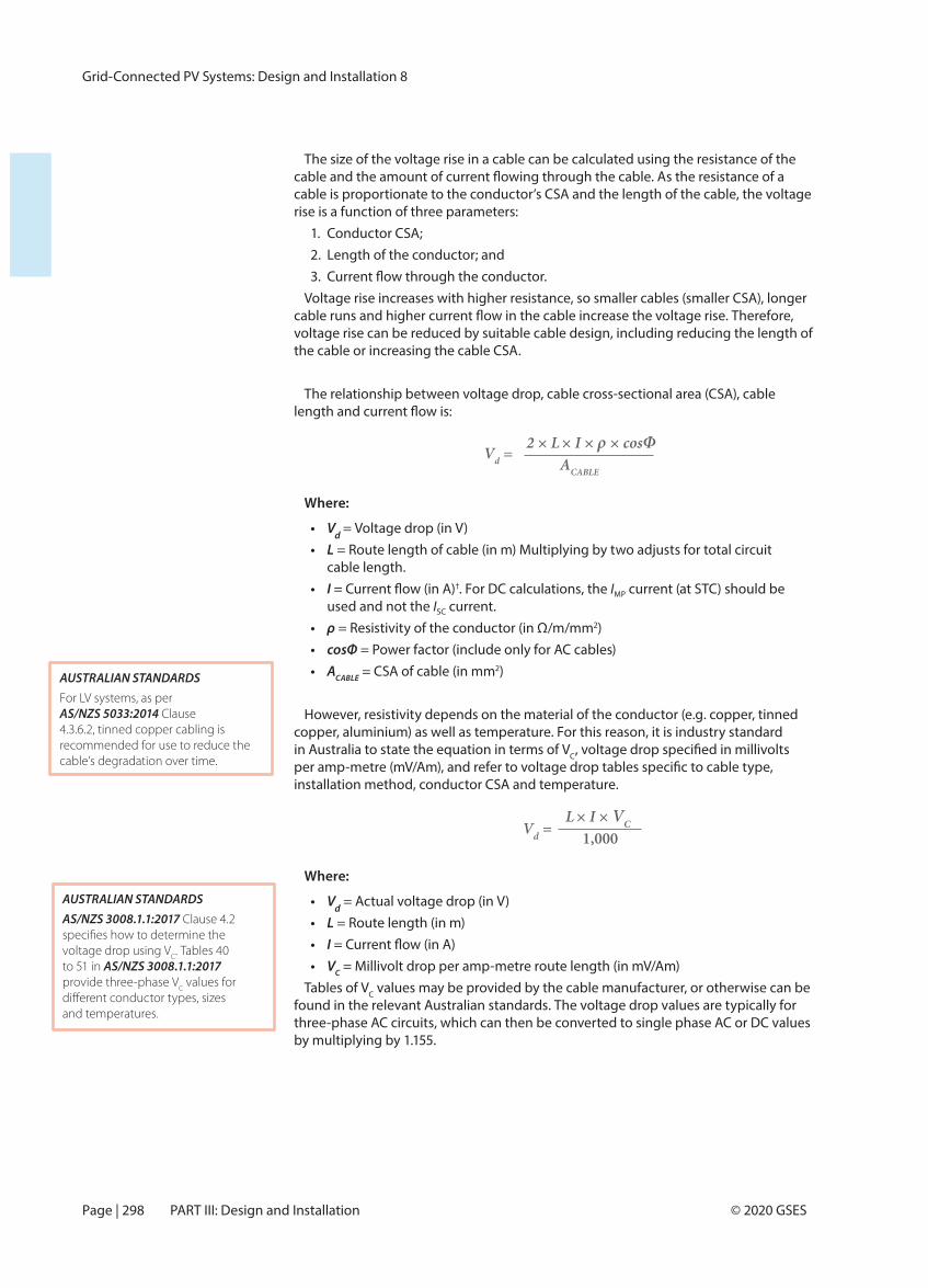
The size of the voltage rise in a cable can be calculated using the resistance of the
cable is proportionate to the conductor’s CSA and the length of the cable, the voltage rise is a function of three parameters:
1. Conductor CSA;2. Length of the conductor; and3.
Voltage rise increases with higher resistance, so smaller cables (smaller CSA), longer
voltage rise can be reduced by suitable cable design, including reducing the length of the cable or increasing the cable CSA.
The relationship between voltage drop, cable cross-sectional area (CSA), cable
Where:
• Vd = Voltage drop (in V)• L = Route length of cable (in m) Multiplying by two adjusts for total circuit
cable length.• I †. For DC calculations, the IMP current (at STC) should be
used and not the ISC current.• ρ = Resistivity of the conductor (in Ω/m/mm2)• cosΦ = Power factor (include only for AC cables)• ACABLE = CSA of cable (in mm2)
However, resistivity depends on the material of the conductor (e.g. copper, tinned copper, aluminium) as well as temperature. For this reason, it is industry standard in Australia to state the equation in terms of VC
installation method, conductor CSA and temperature.
Where:
• Vd = Actual voltage drop (in V)• L = Route length (in m)• I• VC = Millivolt drop per amp-metre route length (in mV/Am)
Tables of VC values may be provided by the cable manufacturer, or otherwise can be found in the relevant Australian standards. The voltage drop values are typically for three-phase AC circuits, which can then be converted to single phase AC or DC values by multiplying by 1.155.
AUSTRALIAN STANDARDSFor LV systems, as per AS/NZS 5033:2014 Clause 4.3.6.2, tinned copper cabling is recommended for use to reduce the cable’s degradation over time.
Vd = 2 × L × I × ρ × cosΦ
ACABLE
AUSTRALIAN STANDARDSAS/NZS 3008.1.1:2017 Clause 4.2
voltage drop using VC. Tables 40
to 51 in AS/NZS 3008.1.1:2017 provide three-phase V
C values for
and temperatures.
Vd =L × I × VC
1,000
Grid-Connected PV Systems: Design and Installation 8
Page | 299© 2020 GSES Chapter 14: Cable Design
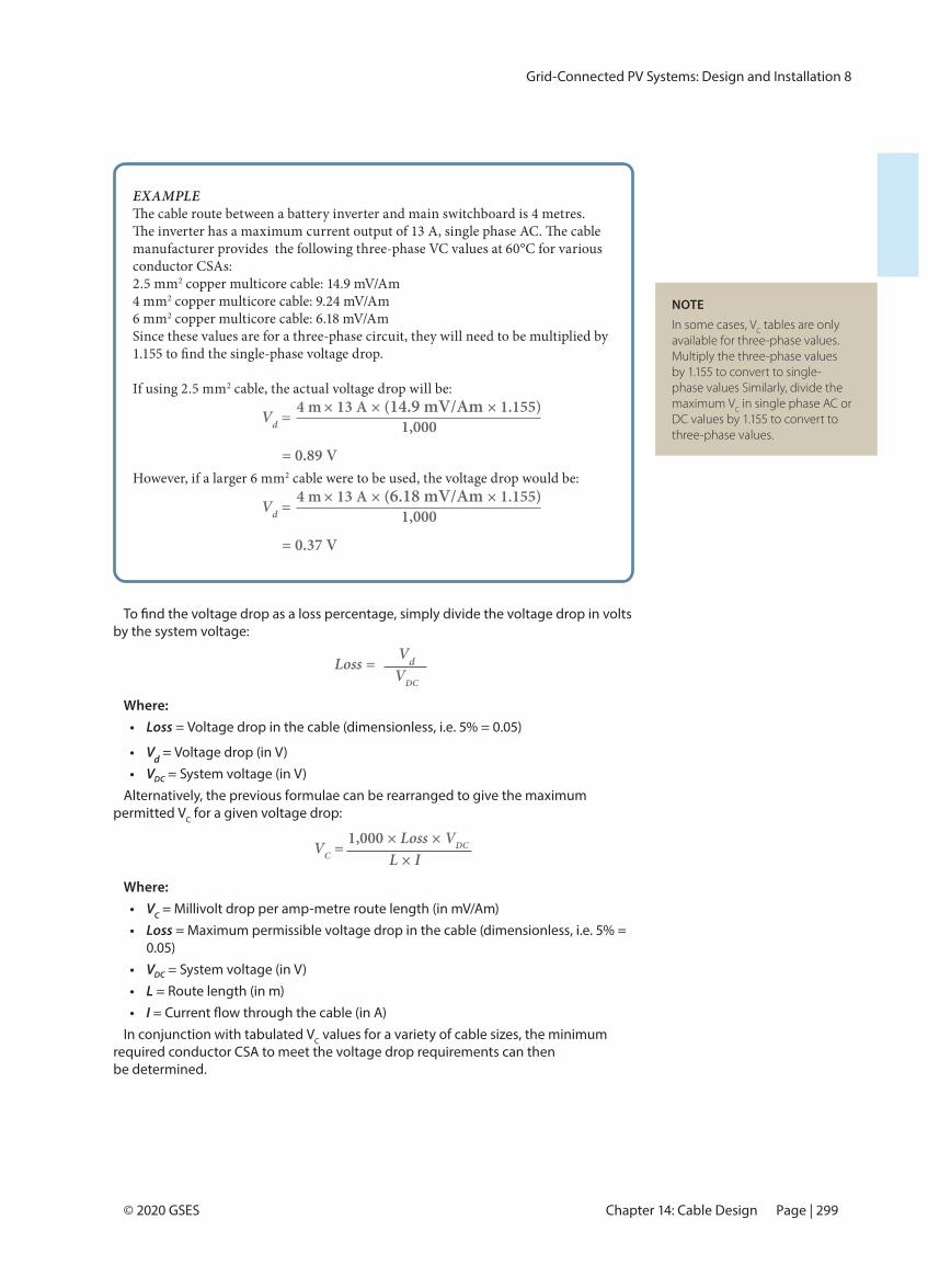
EXAMPLE
manufacturer provides the following three-phase VC values at 60°C for various conductor CSAs:2.5 mm2 copper multicore cable: 14.9 mV/Am4 mm2 copper multicore cable: 9.24 mV/Am6 mm2 copper multicore cable: 6.18 mV/AmSince these values are for a three-phase circuit, they will need to be multiplied by
If using 2.5 mm2 cable, the actual voltage drop will be:
Vd = 4 m × 13 A × (14.9 mV/Am × 1.155)1,000
= 0.89 VHowever, if a larger 6 mm2 cable were to be used, the voltage drop would be:
Vd = 4 m × 13 A × (6.18 mV/Am × 1.155)1,000
= 0.37 V
by the system voltage:
Where:• Loss = Voltage drop in the cable (dimensionless, i.e. 5% = 0.05)
• Vd = Voltage drop (in V)• VDC = System voltage (in V)
Alternatively, the previous formulae can be rearranged to give the maximum permitted VC for a given voltage drop:
Where:• VC = Millivolt drop per amp-metre route length (in mV/Am)• Loss = Maximum permissible voltage drop in the cable (dimensionless, i.e. 5% =
0.05)• VDC = System voltage (in V)• L = Route length (in m)• I
In conjunction with tabulated VC values for a variety of cable sizes, the minimum required conductor CSA to meet the voltage drop requirements can then be determined.
Loss = VdVDC
VC = 1,000 × Loss × VDC
L × I
NOTEIn some cases, V
C tables are only
available for three-phase values. Multiply the three-phase values by 1.155 to convert to single-phase values Similarly, divide the maximum V
C in single phase AC or
DC values by 1.155 to convert to three-phase values.
Grid-Connected PV Systems: Design and Installation 8
Page | 300 © 2020 GSESPART III: Design and Installation
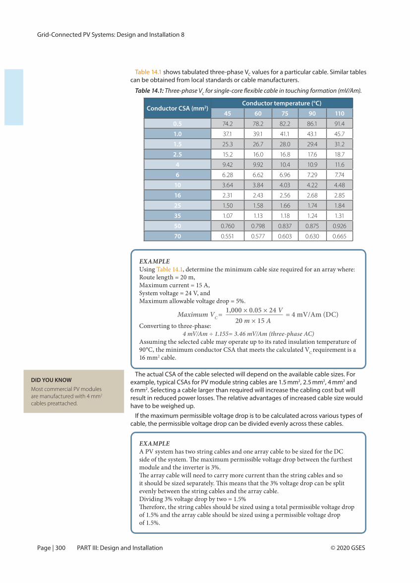
Table 14.1 shows tabulated three-phase VC values for a particular cable. Similar tables can be obtained from local standards or cable manufacturers.
Table 14.1: Three-phase VC
Conductor CSA (mm2)Conductor temperature (°C)
45 60 75 90 110
0.5 74.2 78.2 82.2 86.1 91.4
1.0 37.1 39.1 41.1 43.1 45.7
1.5 25.3 26.7 28.0 29.4 31.2
2.5 15.2 16.0 16.8 17.6 18.7
4 9.42 9.92 10.4 10.9 11.6
6 6.28 6.62 6.96 7.29 7.74
10 3.64 3.84 4.03 4.22 4.48
16 2.31 2.43 2.56 2.68 2.85
25 1.50 1.58 1.66 1.74 1.84
35 1.07 1.13 1.18 1.24 1.31
50 0.760 0.798 0.837 0.875 0.926
70 0.551 0.577 0.603 0.630 0.665
EXAMPLEUsing Table 14.1, determine the minimum cable size required for an array where:Route length = 20 m,Maximum current = 15 A,System voltage = 24 V, andMaximum allowable voltage drop = 5%.
1,000 × 0.05 × 24 VMaximum VC = 20 m × 15 A = 4 mV/Am (DC)
Converting to three-phase:4 mV/Am ÷ 1.155= 3.46 mV/Am (three-phase AC)
Assuming the selected cable may operate up to its rated insulation temperature of 90°C, the minimum conductor CSA that meets the calculated VC requirement is a 16 mm2 cable.
The actual CSA of the cable selected will depend on the available cable sizes. For example, typical CSAs for PV module string cables are 1.5 mm2, 2.5 mm2, 4 mm2 and 6 mm2. Selecting a cable larger than required will increase the cabling cost but will result in reduced power losses. The relative advantages of increased cable size would have to be weighed up.
If the maximum permissible voltage drop is to be calculated across various types of cable, the permissible voltage drop can be divided evenly across these cables.
EXAMPLEA PV system has two string cables and one array cable to be sized for the DC
module and the inverter is 3%.
evenly between the string cables and the array cable.Dividing 3% voltage drop by two = 1.5%
of 1.5% and the array cable should be sized using a permissible voltage drop of 1.5%.
DID YOU KNOWMost commercial PV modules are manufactured with 4 mm2 cables preattached.
Grid-Connected PV Systems: Design and Installation 8
Page | 301© 2020 GSES Chapter 14: Cable Design
14.1.3 Cable Routes and LengthThe cable routes in a grid-connected PV system are initially dependent on the locations of the system components. However, the locations of the system components may be chosen so that the resulting cable routes meet the performance
As shown in Section 14.1.2, the voltage drop in a cable is proportional to the length of the cable. Therefore, using cable routes that minimise the cable lengths will mean that smaller cables can be used without excessive voltage drops. The voltage drop is also proportional to the amount of current that is being carried by the cable. This means that cables with higher currents should be kept as short as possible. The requirement to meet the correct cable sizing and the system’s cabling costs should be applied when locating the system equipment and determining cable lengths and routes.
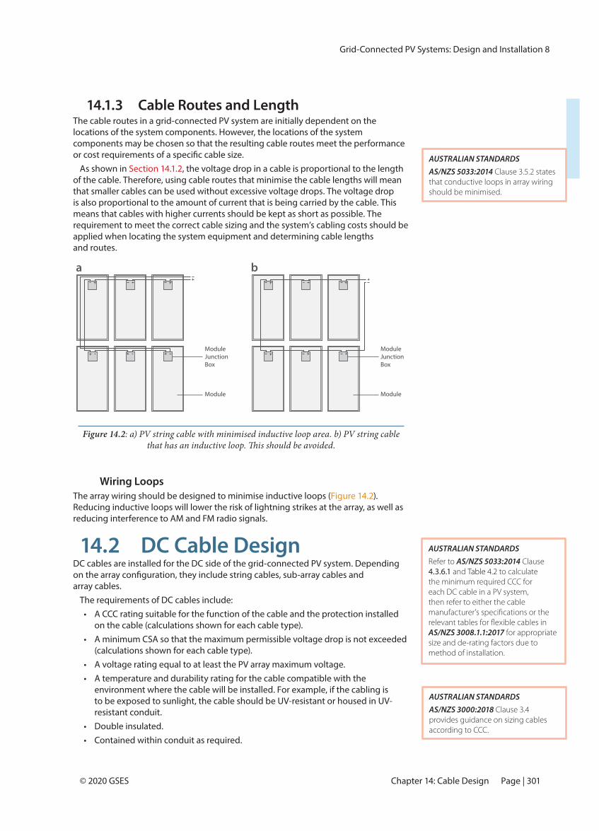
Wiring LoopsThe array wiring should be designed to minimise inductive loops ( ). Reducing inductive loops will lower the risk of lightning strikes at the array, as well as reducing interference to AM and FM radio signals.
14.2 DC Cable Design DC cables are installed for the DC side of the grid-connected PV system. Depending
array cables.The requirements of DC cables include:
• A CCC rating suitable for the function of the cable and the protection installed on the cable (calculations shown for each cable type).
• A minimum CSA so that the maximum permissible voltage drop is not exceeded (calculations shown for each cable type).
• A voltage rating equal to at least the PV array maximum voltage. • A temperature and durability rating for the cable compatible with the
environment where the cable will be installed. For example, if the cabling is to be exposed to sunlight, the cable should be UV-resistant or housed in UV-resistant conduit.
• Double insulated. • Contained within conduit as required.
a b
ModuleJunctionBox
Module
ModuleJunctionBox
Module
Figure 14.2: a) PV string cable with minimised inductive loop area. b) PV string cable
AUSTRALIAN STANDARDSAS/NZS 5033:2014 Clause 3.5.2 states that conductive loops in array wiring should be minimised.
AUSTRALIAN STANDARDSAS/NZS 3000:2018 Clause 3.4 provides guidance on sizing cables according to CCC.
AUSTRALIAN STANDARDSRefer to AS/NZS 5033:2014 Clause 4.3.6.1 and Table 4.2 to calculate the minimum required CCC for each DC cable in a PV system, then refer to either the cable
AS/NZS 3008.1.1:2017 for appropriate size and de-rating factors due to method of installation.
Grid-Connected PV Systems: Design and Installation 8
Page | 302 © 2020 GSESPART III: Design and Installation
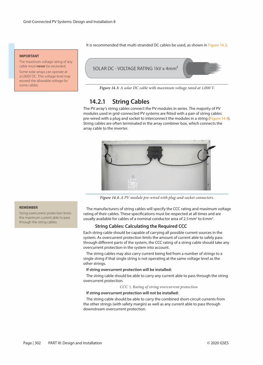
It is recommended that multi-stranded DC cables be used, as shown in Figure 14.3.
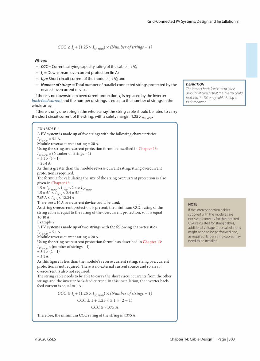
14.2.1 String Cables The PV array’s string cables connect the PV modules in series. The majority of PV
pre-wired with a plug and socket to interconnect the modules in a string ( ). String cables are often terminated in the array combiner box, which connects the array cable to the inverter.
The manufacturers of string cables will specify the CCC rating and maximum voltage
usually available for cables of a nominal conductor area of 2.5 mm2 to 6 mm2.
String Cables: Calculating the Required CCCEach string cable should be capable of carrying all possible current sources in the system. As overcurrent protection limits the amount of current able to safely pass
overcurrent protection in the system into account.The string cables may also carry current being fed from a number of strings to a
single string if that single string is not operating at the same voltage level as the other strings.
If string overcurrent protection will be installed: The string cable should be able to carry any current able to pass through the string
overcurrent protection. CCC ≥ Rating of string overcurrent protection
If string overcurrent protection will not be installed: The string cable should be able to carry the combined short-circuit currents from
the other strings (with safety margin) as well as any current able to pass through downstream overcurrent protection.
Figure 14.4: A PV module pre-wired with plug-and-socket connectors.
REMEMBERString overcurrent protection limits the maximum current able to pass through the string cables.
Figure 14.3: A solar DC cable with maximum voltage rated at 1,000 V.
SOLAR DC - VOLTAGE RATING 1kV x 4mm²
© 2015
IMPORTANTThe maximum voltage rating of any cable must never be exceeded.
Some solar arrays can operate at ±1,000V DC. This voltage level may exceed the allowable voltage for some cables.
Grid-Connected PV Systems: Design and Installation 8
Page | 303© 2020 GSES Chapter 14: Cable Design
Where:• CCC = Current carrying capacity rating of the cable (in A);• In = Downstream overcurrent protection (in A)• ISC = Short circuit current of the module (in A); and• Number of strings = Total number of parallel connected strings protected by the
nearest overcurrent device.If there is no downstream overcurrent protection, In is replaced by the inverter
back-feed current and the number of strings is equal to the number of strings in the whole array.
If there is only one string in the whole array, the string cable should be rated to carry the short circuit current of the string, with a safety margin: 1.25 × ISC MOD.
EXAMPLE 1
ISC MOD = 5.1 A.Module reverse current rating = 20 A.Using the string overcurrent protection formula described in Chapter 13:ISC MOD × (Number of strings – 1)= 5.1 × (5 – 1)= 20.4 AAs this is greater than the module reverse current rating, string overcurrent protection is required.
given in Chapter 13:1.5 × ISC ≤ ITRIP ≤ 2.4 × ISC MOD1.5 × 5.1 ≤ ITRIP ≤ 2.4 × 5.17.65 A ≤ ITRIP ≤ 12.24 A
A overcurrent device could be used.As string overcurrent protection is present, the minimum CCC rating of the string cable is equal to the rating of the overcurrent protection, so it is equal to 10 A.Example 2A PV system is made up of two strings with the following characteristics:ISC MOD = 5.1 A.Module reverse current rating = 20 A.Using the string overcurrent protection formula as described in Chapter 13:ISC MOD × (number of strings – 1)= 5.1 × (2 – 1)= 5.1 A
overcurrent is also not required.
strings and the inverter back-feed current. In this installation, the inverter back-feed current is equal to 1 A.
A.
CCC ≥ In + (1.25 × ISC MOD) × (Number of strings − 1)CCC ≥ 1 + 1.25 × 5.1 × (2 − 1)
CCC ≥ 7.375 A
NOTEIf the interconnection cables supplied with the modules are not sized correctly for the required CSA calculated for string cables, additional voltage drop calculations might need to be performed and, as required, larger string cables may need to be installed.
CCC ≥ In + (1.25 × ISC MOD) × (Number of strings − 1)
DEFINITIONThe inverter back-feed current is the amount of current that the inverter could feed into the DC array cable during a fault condition.
Grid-Connected PV Systems: Design and Installation 8
Page | 304 © 2020 GSESPART III: Design and Installation
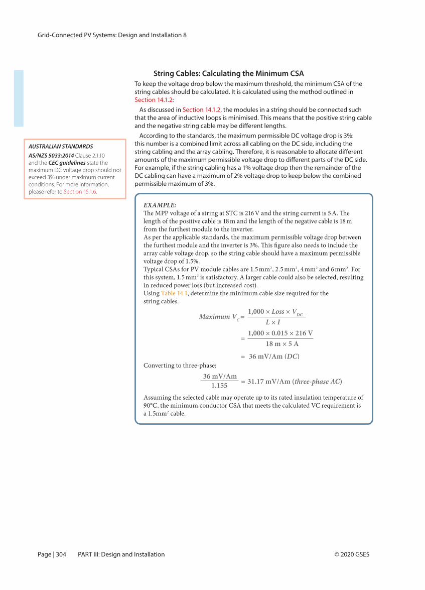
String Cables: Calculating the Minimum CSATo keep the voltage drop below the maximum threshold, the minimum CSA of the string cables should be calculated. It is calculated using the method outlined in Section 14.1.2:
As discussed in Section 14.1.2, the modules in a string should be connected such that the area of inductive loops is minimised. This means that the positive string cable
According to the standards, the maximum permissible DC voltage drop is 3%: this number is a combined limit across all cabling on the DC side, including the
For example, if the string cabling has a 1% voltage drop then the remainder of the DC cabling can have a maximum of 2% voltage drop to keep below the combined permissible maximum of 3%.
EXAMPLE: V and the string current is 5
length of the positive cable is 18 m and the length of the negative cable is 18 m from the furthest module to the inverter. As per the applicable standards, the maximum permissible voltage drop between
array cable voltage drop, so the string cable should have a maximum permissible voltage drop of 1.5%. Typical CSAs for PV module cables are 1.5 mm2, 2.5 mm2, 4 mm2 and 6 mm2. For this system, 1.5 mm2 is satisfactory. A larger cable could also be selected, resulting in reduced power loss (but increased cost).Using Table 14.1, determine the minimum cable size required for the string cables.
Converting to three-phase:
Assuming the selected cable may operate up to its rated insulation temperature of 90°C, the minimum conductor CSA that meets the calculated VC requirement is a 1.5mm2 cable.
AUSTRALIAN STANDARDSAS/NZS 5033:2014 Clause 2.1.10 and the CEC guidelines state the maximum DC voltage drop should not exceed 3% under maximum current conditions. For more information, please refer to Section 15.1.6.
1,000 × Loss × VDCMaximum VC = L × I 1,000 × 0.015 × 216 V
= 18 m × 5 A
= 36 mV/Am (DC)
36 mV/Am 1.155 = 31.17 mV/Am (three-phase AC)
Grid-Connected PV Systems: Design and Installation 8
Page | 305© 2020 GSES Chapter 14: Cable Design
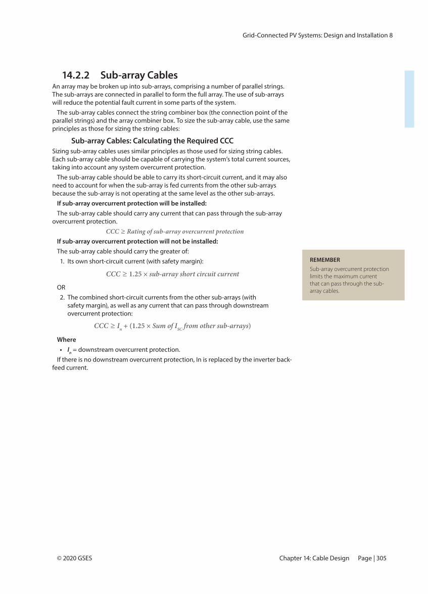
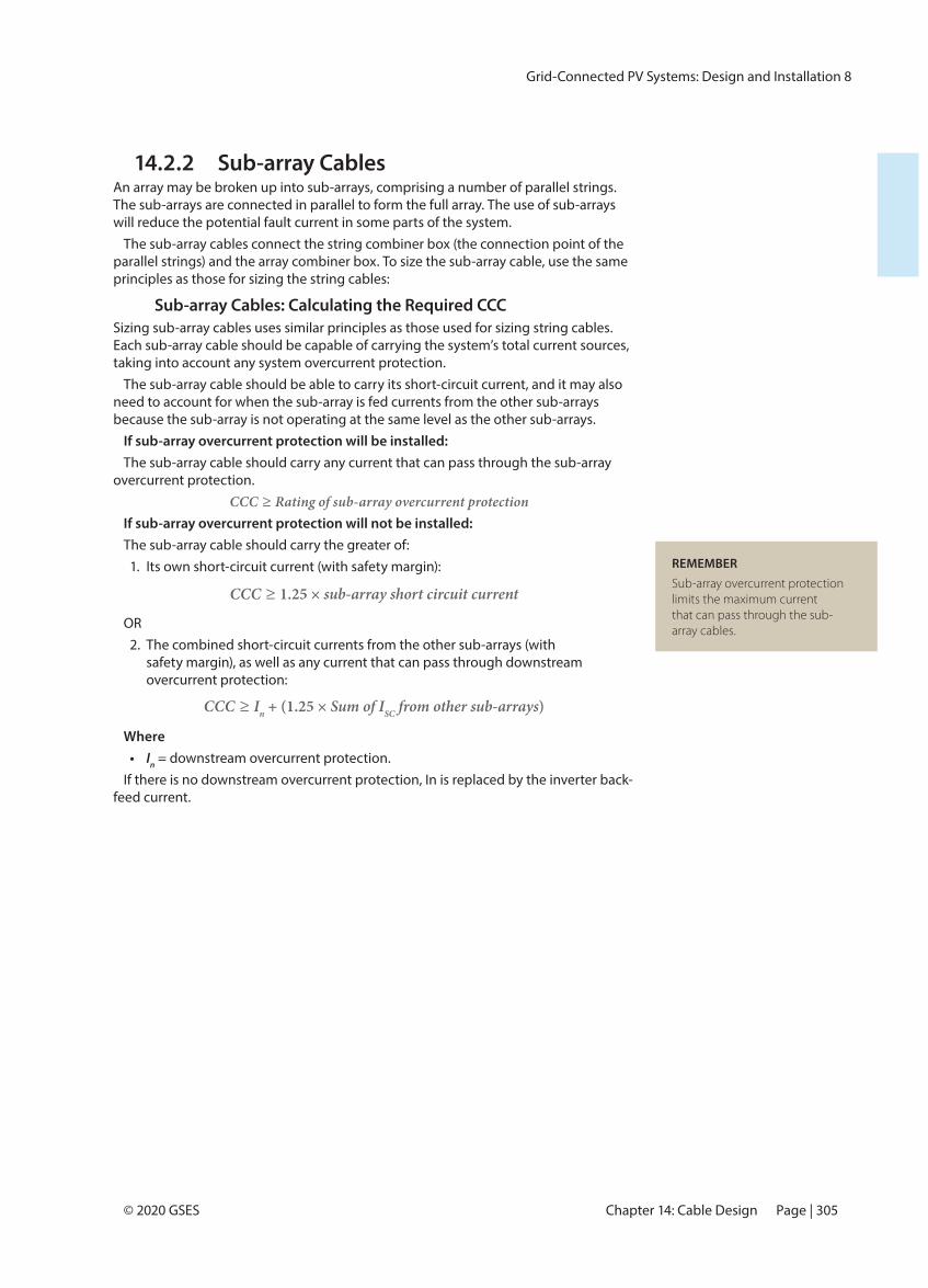
14.2.2 Sub-array CablesAn array may be broken up into sub-arrays, comprising a number of parallel strings. The sub-arrays are connected in parallel to form the full array. The use of sub-arrays will reduce the potential fault current in some parts of the system.
The sub-array cables connect the string combiner box (the connection point of the parallel strings) and the array combiner box. To size the sub-array cable, use the same principles as those for sizing the string cables:
Sub-array Cables: Calculating the Required CCCSizing sub-array cables uses similar principles as those used for sizing string cables. Each sub-array cable should be capable of carrying the system’s total current sources, taking into account any system overcurrent protection.
The sub-array cable should be able to carry its short-circuit current, and it may also need to account for when the sub-array is fed currents from the other sub-arrays because the sub-array is not operating at the same level as the other sub-arrays.
If sub-array overcurrent protection will be installed: The sub-array cable should carry any current that can pass through the sub-array
overcurrent protection. CCC ≥ Rating of sub-array overcurrent protection
If sub-array overcurrent protection will not be installed: The sub-array cable should carry the greater of:
1. Its own short-circuit current (with safety margin):
OR2. The combined short-circuit currents from the other sub-arrays (with
safety margin), as well as any current that can pass through downstream overcurrent protection:
Where• In = downstream overcurrent protection.
If there is no downstream overcurrent protection, In is replaced by the inverter back-feed current.
REMEMBERSub-array overcurrent protection limits the maximum current that can pass through the sub-array cables.
CCC ≥ 1.25 × sub-array short circuit current
CCC ≥ In + (1.25 × Sum of ISC from other sub-arrays)

Grid-Connected PV Systems: Design and Installation 8
Page | 306 © 2020 GSESPART III: Design and Installation
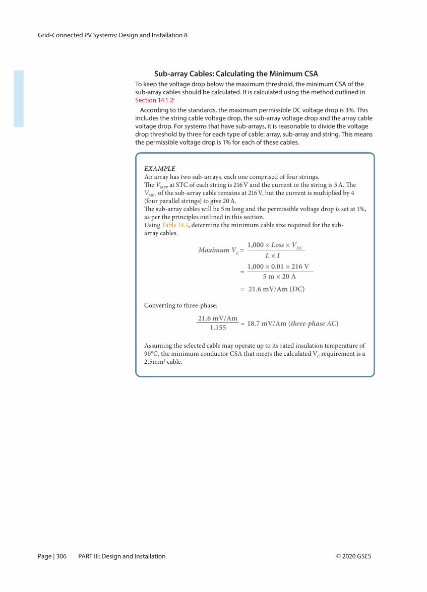
Sub-array Cables: Calculating the Minimum CSATo keep the voltage drop below the maximum threshold, the minimum CSA of the sub-array cables should be calculated. It is calculated using the method outlined in Section 14.1.2:
According to the standards, the maximum permissible DC voltage drop is 3%. This includes the string cable voltage drop, the sub-array voltage drop and the array cable voltage drop. For systems that have sub-arrays, it is reasonable to divide the voltage drop threshold by three for each type of cable: array, sub-array and string. This means the permissible voltage drop is 1% for each of these cables.
EXAMPLEAn array has two sub-arrays, each one comprised of four strings.
VMPP at STC of each string is 216 V and the current in the string is 5 VMPP of the sub-array cable remains at 216 V, but the current is multiplied by 4 (four parallel strings) to give 20 A.
m long and the permissible voltage drop is set at 1%, as per the principles outlined in this section. Using Table 14.1, determine the minimum cable size required for the sub-array cables.
Converting to three-phase:
Assuming the selected cable may operate up to its rated insulation temperature of 90°C, the minimum conductor CSA that meets the calculated VC requirement is a 2.5mm2 cable.
21.6 mV/Am 1.155 = 18.7 mV/Am (three-phase AC)
1,000 × Loss × VDCMaximum VC = L × I 1,000 × 0.01 × 216 V
= 5 m × 20 A
= 21.6 mV/Am (DC)
Grid-Connected PV Systems: Design and Installation 8
Page | 307© 2020 GSES Chapter 14: Cable Design
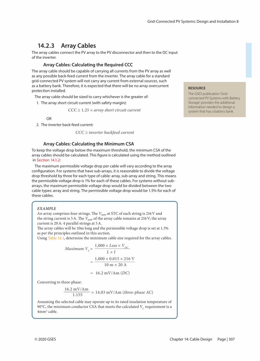
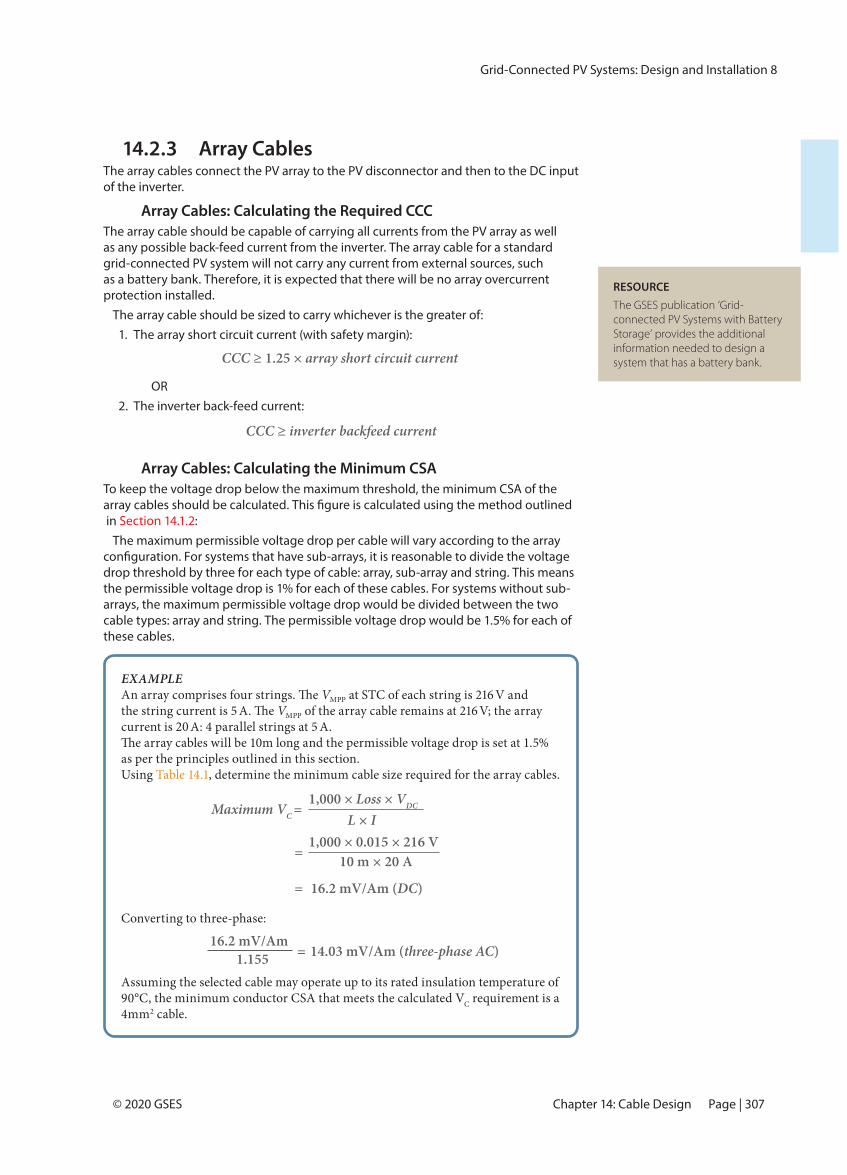
14.2.3 Array CablesThe array cables connect the PV array to the PV disconnector and then to the DC input of the inverter.
Array Cables: Calculating the Required CCCThe array cable should be capable of carrying all currents from the PV array as well as any possible back-feed current from the inverter. The array cable for a standard grid-connected PV system will not carry any current from external sources, such as a battery bank. Therefore, it is expected that there will be no array overcurrent protection installed.
The array cable should be sized to carry whichever is the greater of:1. The array short circuit current (with safety margin):
OR 2. The inverter back-feed current:
Array Cables: Calculating the Minimum CSATo keep the voltage drop below the maximum threshold, the minimum CSA of the
in :
The maximum permissible voltage drop per cable will vary according to the array
drop threshold by three for each type of cable: array, sub-array and string. This means the permissible voltage drop is 1% for each of these cables. For systems without sub-arrays, the maximum permissible voltage drop would be divided between the two cable types: array and string. The permissible voltage drop would be 1.5% for each of these cables.
CCC ≥ 1.25 × array short circuit current
CCC ≥ inverter backfeed current
EXAMPLEVMPP at STC of each string is 216 V and
the string current is 5 VMPP of the array cable remains at 216 V; the array current is 20 A: 4 parallel strings at 5 A.
as per the principles outlined in this section. Using Table 14.1, determine the minimum cable size required for the array cables.
Converting to three-phase:
Assuming the selected cable may operate up to its rated insulation temperature of 90°C, the minimum conductor CSA that meets the calculated VC requirement is a 4mm2 cable.
1,000 × Loss × VDCMaximum VC = L × I 1,000 × 0.015 × 216 V
= 10 m × 20 A
= 16.2 mV/Am (DC)
RESOURCEThe GSES publication ‘Grid-connected PV Systems with Battery Storage’ provides the additional information needed to design a system that has a battery bank.
16.2 mV/Am 1.155 = 14.03 mV/Am (three-phase AC)

Grid-Connected PV Systems: Design and Installation 8
Page | 308 © 2020 GSESPART III: Design and Installation
14.3 AC Cable DesignThe AC cables on a grid-connected PV system are used between the inverter and the grid connection point. The AC cable design for a grid-connected PV system will relate to the cables between the inverter and the switchboard (or the distribution board if applicable). However, potential voltage rise at the inverter could require a reassessment of the suitability of the wiring between the switchboard (or distribution board) and the grid connection point.
14.3.1 AC Inverter CableThe AC inverter cable connects the inverter to the main electrical supply. This is usually at the switchboard, but some installations might connect the inverter to the nearest distribution board. For example, an array installed on a shed roof could be connected to the grid via the shed distribution board. As outlined in Section 11.6, the nearest distribution board may be used only if the PV system has a net metering arrangement.
The voltage rating of the AC inverter cable will be the same as that for standard building cables, around 230 VRMS. The required CCC and minimum CSA calculations are set out in this section. The cable must also comply with the following requirements:
• A temperature and durability rating relative to the environment in which the cable will be installed. For example, if the cabling is exposed, it should be UV-resistant material or housed in UV-resistant conduit.
• Insulated or enclosed as required.
AC Inverter Cable: Calculating the Required CCCThe AC inverter cable connects the inverter and the switchboard (or distribution board). Therefore, the CCC of the AC cables must be greater than the maximum AC output current from the inverter.
The AC cable should also be able to carry any fault current from the grid, such as a fault on the AC cable between the inverter and the switchboard. This fault current is limited by the circuit breaker at the switchboard and so the CCC of the AC cable should be greater than or equal to the rating of this circuit breaker.
AUSTRALIAN STANDARDSAS/NZS 3008.1.1:2017 states the DC and AC de-rated CCC for
AS/NZS 4777.1:2016 outlines the AC cable requirements in a grid-connected PV system.
REMEMBERAccording to the CEC guidelines, the maximum voltage drop between the inverter and the switchboard should be 1%.
Grid-Connected PV Systems: Design and Installation 8
Page | 309© 2020 GSES Chapter 14: Cable Design
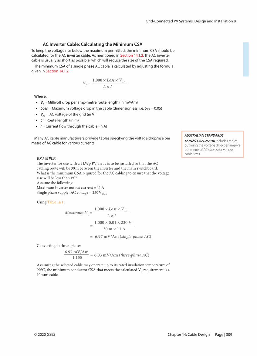
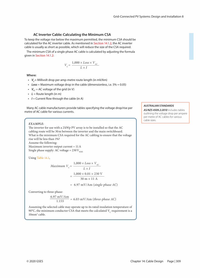
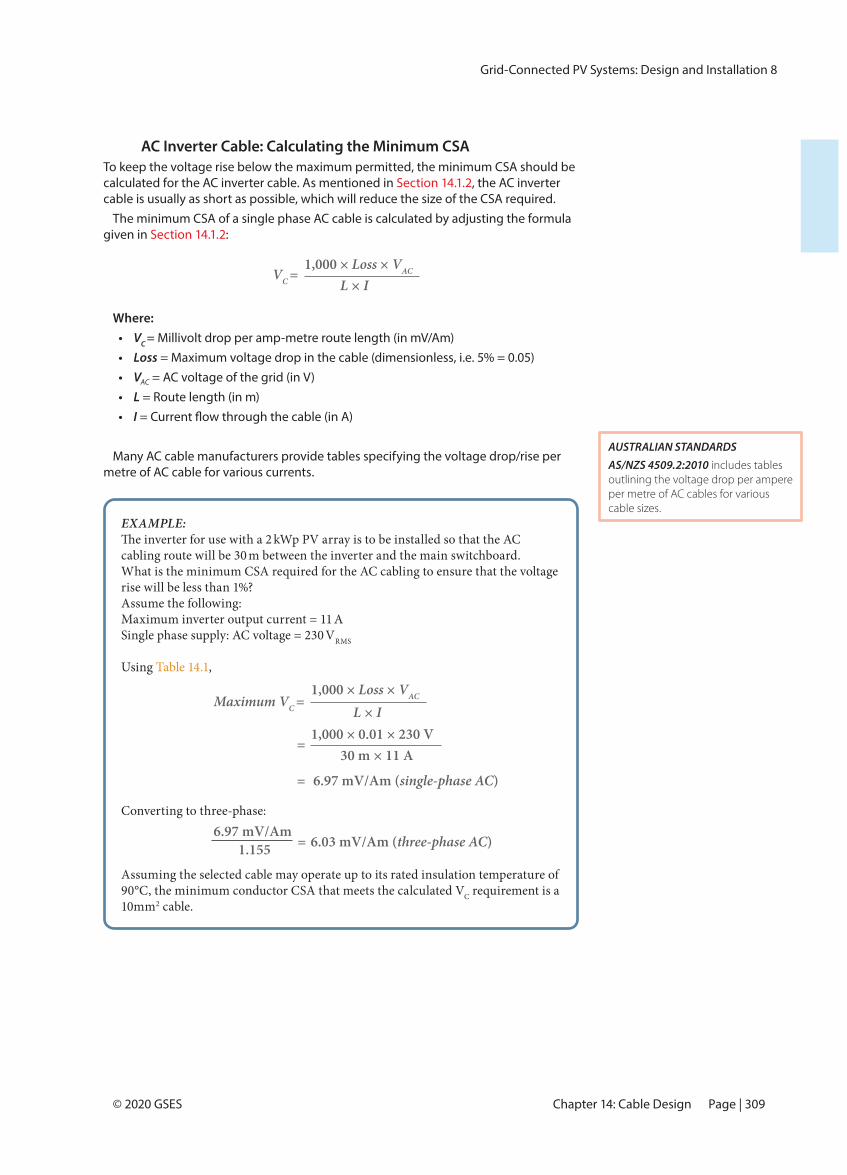
AC Inverter Cable: Calculating the Minimum CSATo keep the voltage rise below the maximum permitted, the minimum CSA should be calculated for the AC inverter cable. As mentioned in Section 14.1.2, the AC inverter cable is usually as short as possible, which will reduce the size of the CSA required.
The minimum CSA of a single phase AC cable is calculated by adjusting the formula given in Section 14.1.2:
Where:• VC = Millivolt drop per amp-metre route length (in mV/Am)• Loss = Maximum voltage drop in the cable (dimensionless, i.e. 5% = 0.05)• VAC = AC voltage of the grid (in V)• L = Route length (in m)• I
Many AC cable manufacturers provide tables specifying the voltage drop/rise per metre of AC cable for various currents.
1,000 × Loss × VACVC = L × I
AUSTRALIAN STANDARDSAS/NZS 4509.2:2010 includes tables outlining the voltage drop per ampere per metre of AC cables for various cable sizes.
EXAMPLE: kWp PV array is to be installed so that the AC
cabling route will be 30 m between the inverter and the main switchboard.What is the minimum CSA required for the AC cabling to ensure that the voltage rise will be less than 1%?Assume the following:Maximum inverter output current = 11 ASingle phase supply: AC voltage = 230 VRMS
Using Table 14.1,
Converting to three-phase:
Assuming the selected cable may operate up to its rated insulation temperature of 90°C, the minimum conductor CSA that meets the calculated VC requirement is a 10mm2 cable.
1,000 × Loss × VACMaximum VC = L × I 1,000 × 0.01 × 230 V
= 30 m × 11 A
= 6.97 mV/Am (single-phase AC)
6.97 mV/Am 1.155 = 6.03 mV/Am (three-phase AC)
Grid-Connected PV Systems: Design and Installation 8
Page | 310 © 2020 GSESPART III: Design and Installation
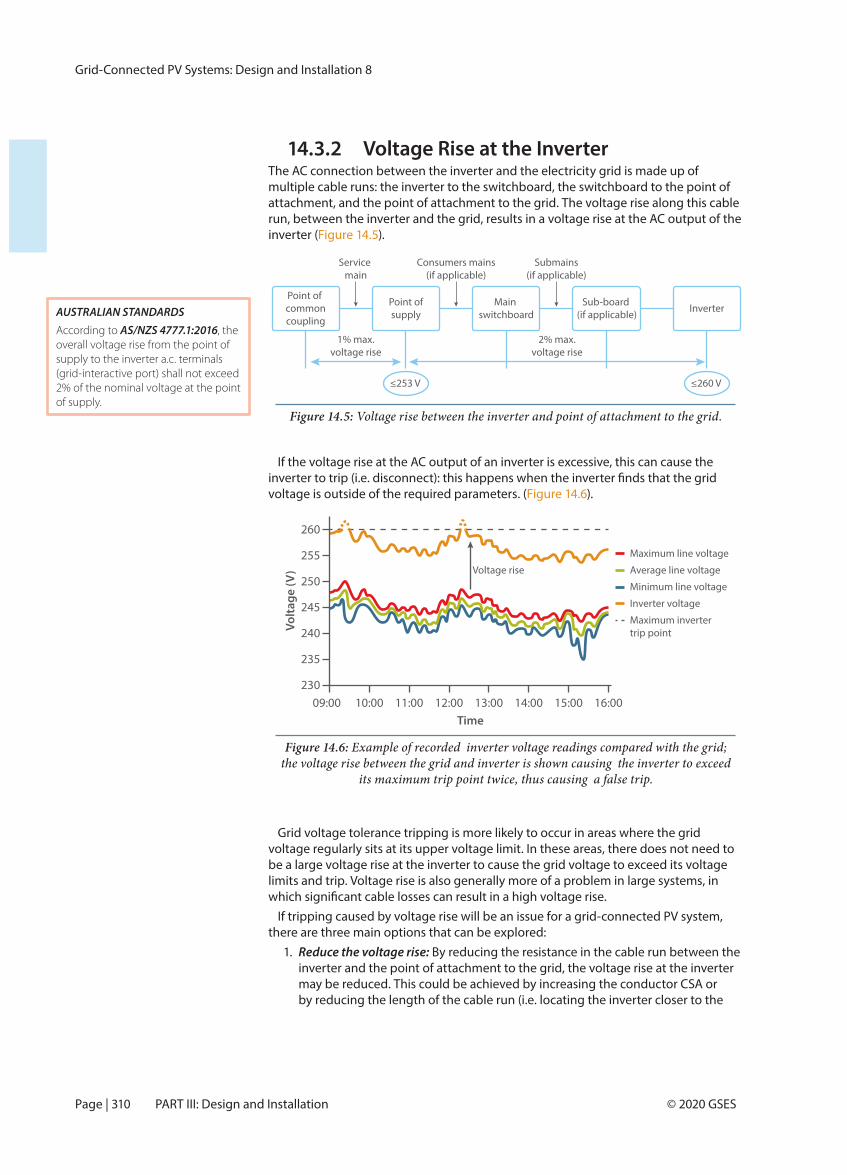
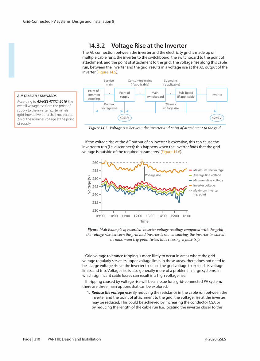
14.3.2 Voltage Rise at the InverterThe AC connection between the inverter and the electricity grid is made up of multiple cable runs: the inverter to the switchboard, the switchboard to the point of attachment, and the point of attachment to the grid. The voltage rise along this cable run, between the inverter and the grid, results in a voltage rise at the AC output of the inverter ( ).
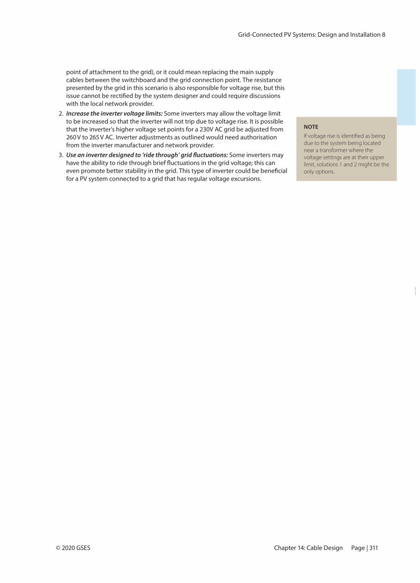
If the voltage rise at the AC output of an inverter is excessive, this can cause the
voltage is outside of the required parameters. ( ).
Grid voltage tolerance tripping is more likely to occur in areas where the grid voltage regularly sits at its upper voltage limit. In these areas, there does not need to be a large voltage rise at the inverter to cause the grid voltage to exceed its voltage limits and trip. Voltage rise is also generally more of a problem in large systems, in
If tripping caused by voltage rise will be an issue for a grid-connected PV system, there are three main options that can be explored:
1. Reduce the voltage rise: By reducing the resistance in the cable run between the inverter and the point of attachment to the grid, the voltage rise at the inverter may be reduced. This could be achieved by increasing the conductor CSA or by reducing the length of the cable run (i.e. locating the inverter closer to the
Point ofsupply
Main switchboard
Sub-board (if applicable)
Point of commoncoupling
Inverter
Service main
Consumers mains(if applicable)
Submains(if applicable)
2% max.voltage rise
1% max.voltage rise
≤253 V ≤260 V
Figure 14.5: Voltage rise between the inverter and point of attachment to the grid.
09:00230
235
240
245
250
255
260
10:00 11:00 12:00 13:00Time
Volta
ge (V
)
14:00 15:00 16:00
Maximum invertertrip point
Voltage rise
Maximum line voltage
Average line voltage
Minimum line voltage
Inverter voltage
Figure 14.6: Example of recorded inverter voltage readings compared with the grid; the voltage rise between the grid and inverter is shown causing the inverter to exceed
its maximum trip point twice, thus causing a false trip.
AUSTRALIAN STANDARDS According to AS/NZS 4777.1:2016, the overall voltage rise from the point of supply to the inverter a.c. terminals (grid-interactive port) shall not exceed 2% of the nominal voltage at the point of supply.
Grid-Connected PV Systems: Design and Installation 8
Page | 311© 2020 GSES Chapter 14: Cable Design
point of attachment to the grid), or it could mean replacing the main supply cables between the switchboard and the grid connection point. The resistance presented by the grid in this scenario is also responsible for voltage rise, but this
with the local network provider.2. Increase the inverter voltage limits: Some inverters may allow the voltage limit
to be increased so that the inverter will not trip due to voltage rise. It is possible that the inverter’s higher voltage set points for a 230V AC grid be adjusted from 260 V to 265 V AC. Inverter adjustments as outlined would need authorisation from the inverter manufacturer and network provider.
3. Some inverters may
for a PV system connected to a grid that has regular voltage excursions.
NOTE
due to the system being located near a transformer where the voltage settings are at their upper limit, solutions 1 and 2 might be the only options.
Grid-Connected PV Systems: Design and Installation 8
Page | 312 © 2020 GSESPART III: Design and Installation
Chapter 14 QuizQuestion 1
a. According to AS/NZS 5033:2014, what is the maximum allowable DC voltage drop in a solar PV system?
b. According to AS/NZS 5033:2014, what is the maximum allowable AC voltage drop in a solar PV system?
Question 2Why should the CCC of all cables be known?Question 3An array has four strings of nine modules and the
• Module IMP = 5.2 A• Module VMPP = 35.1 V• String cable length = 14 m• Array cable length = 22 m
AS/NZS 3008.1.1:2017 Table 47 and a maximum conductor temperature of 90°C.
voltage drop on the string cables and a 1.5% voltage drop on the array cables.
a. Calculate the minimum string cable CSA.b. Calculate the minimum array cable CSA.
Question 4You are supplied with a reel of 4 mm2 cable to use as the
• Module IMP = 7.9 A• Module VMPP = 36.1 V• String cable length = 20 m• Array cable length = 11 m
AS/NZS 3008.1.1:2017 Table 47 and a maximum conductor temperature of 60°C.
a. Calculate the % voltage drop on the array cable.b. Calculate the maximum allowable % voltage drop on
the string cables.c. Calculate the minimum string cable CSA.
Question 5
switchboard is 26 m. What is the minimum cable CSA that will ensure the voltage drop will be less than 1%? Assume the following:
• IAC = 12 A• V = Single-phase 230 VRMS
AS/NZS 3008.1.1:2017 Table 47 and a maximum conductor temperature of 90°C.Question 6Why should cables be as short as possible? How can system design and installation minimise the length of system cables?
Grid-Connected PV Systems: Design and Installation 8
Page | 305© 2020 GSES Chapter 14: Cable Design
14.2.2 Sub-array CablesAn array may be broken up into sub-arrays, comprising a number of parallel strings. The sub-arrays are connected in parallel to form the full array. The use of sub-arrays will reduce the potential fault current in some parts of the system.
The sub-array cables connect the string combiner box (the connection point of the parallel strings) and the array combiner box. To size the sub-array cable, use the same principles as those for sizing the string cables:
Sub-array Cables: Calculating the Required CCCSizing sub-array cables uses similar principles as those used for sizing string cables. Each sub-array cable should be capable of carrying the system’s total current sources, taking into account any system overcurrent protection.
The sub-array cable should be able to carry its short-circuit current, and it may also need to account for when the sub-array is fed currents from the other sub-arrays because the sub-array is not operating at the same level as the other sub-arrays.
If sub-array overcurrent protection will be installed: The sub-array cable should carry any current that can pass through the sub-array
overcurrent protection. CCC ≥ Rating of sub-array overcurrent protection
If sub-array overcurrent protection will not be installed: The sub-array cable should carry the greater of:
1. Its own short-circuit current (with safety margin):
OR2. The combined short-circuit currents from the other sub-arrays (with
safety margin), as well as any current that can pass through downstream overcurrent protection:
Where• In = downstream overcurrent protection.
If there is no downstream overcurrent protection, In is replaced by the inverter back-feed current.
REMEMBERSub-array overcurrent protection limits the maximum current that can pass through the sub-array cables.
CCC ≥ 1.25 × sub-array short circuit current
CCC ≥ In + (1.25 × Sum of ISC from other sub-arrays)
Grid-Connected PV Systems: Design and Installation 8
Page | 306 © 2020 GSESPART III: Design and Installation
Sub-array Cables: Calculating the Minimum CSATo keep the voltage drop below the maximum threshold, the minimum CSA of the sub-array cables should be calculated. It is calculated using the method outlined in Section 14.1.2:
According to the standards, the maximum permissible DC voltage drop is 3%. This includes the string cable voltage drop, the sub-array voltage drop and the array cable voltage drop. For systems that have sub-arrays, it is reasonable to divide the voltage drop threshold by three for each type of cable: array, sub-array and string. This means the permissible voltage drop is 1% for each of these cables.
EXAMPLEAn array has two sub-arrays, each one comprised of four strings.
VMPP at STC of each string is 216 V and the current in the string is 5 VMPP of the sub-array cable remains at 216 V, but the current is multiplied by 4 (four parallel strings) to give 20 A.
m long and the permissible voltage drop is set at 1%, as per the principles outlined in this section. Using Table 14.1, determine the minimum cable size required for the sub-array cables.
Converting to three-phase:
Assuming the selected cable may operate up to its rated insulation temperature of 90°C, the minimum conductor CSA that meets the calculated VC requirement is a 2.5mm2 cable.
21.6 mV/Am 1.155 = 18.7 mV/Am (three-phase AC)
1,000 × Loss × VDCMaximum VC = L × I 1,000 × 0.01 × 216 V
= 5 m × 20 A
= 21.6 mV/Am (DC)
Grid-Connected PV Systems: Design and Installation 8
Page | 307© 2020 GSES Chapter 14: Cable Design
14.2.3 Array CablesThe array cables connect the PV array to the PV disconnector and then to the DC input of the inverter.
Array Cables: Calculating the Required CCCThe array cable should be capable of carrying all currents from the PV array as well as any possible back-feed current from the inverter. The array cable for a standard grid-connected PV system will not carry any current from external sources, such as a battery bank. Therefore, it is expected that there will be no array overcurrent protection installed.
The array cable should be sized to carry whichever is the greater of:1. The array short circuit current (with safety margin):
OR 2. The inverter back-feed current:
Array Cables: Calculating the Minimum CSATo keep the voltage drop below the maximum threshold, the minimum CSA of the
in :
The maximum permissible voltage drop per cable will vary according to the array
drop threshold by three for each type of cable: array, sub-array and string. This means the permissible voltage drop is 1% for each of these cables. For systems without sub-arrays, the maximum permissible voltage drop would be divided between the two cable types: array and string. The permissible voltage drop would be 1.5% for each of these cables.
CCC ≥ 1.25 × array short circuit current
CCC ≥ inverter backfeed current
EXAMPLEVMPP at STC of each string is 216 V and
the string current is 5 VMPP of the array cable remains at 216 V; the array current is 20 A: 4 parallel strings at 5 A.
as per the principles outlined in this section. Using Table 14.1, determine the minimum cable size required for the array cables.
Converting to three-phase:
Assuming the selected cable may operate up to its rated insulation temperature of 90°C, the minimum conductor CSA that meets the calculated VC requirement is a 4mm2 cable.
1,000 × Loss × VDCMaximum VC = L × I 1,000 × 0.015 × 216 V
= 10 m × 20 A
= 16.2 mV/Am (DC)
RESOURCEThe GSES publication ‘Grid-connected PV Systems with Battery Storage’ provides the additional information needed to design a system that has a battery bank.
16.2 mV/Am 1.155 = 14.03 mV/Am (three-phase AC)

Grid-Connected PV Systems: Design and Installation 8
Page | 308 © 2020 GSESPART III: Design and Installation
14.3 AC Cable DesignThe AC cables on a grid-connected PV system are used between the inverter and the grid connection point. The AC cable design for a grid-connected PV system will relate to the cables between the inverter and the switchboard (or the distribution board if applicable). However, potential voltage rise at the inverter could require a reassessment of the suitability of the wiring between the switchboard (or distribution board) and the grid connection point.
14.3.1 AC Inverter CableThe AC inverter cable connects the inverter to the main electrical supply. This is usually at the switchboard, but some installations might connect the inverter to the nearest distribution board. For example, an array installed on a shed roof could be connected to the grid via the shed distribution board. As outlined in Section 11.6, the nearest distribution board may be used only if the PV system has a net metering arrangement.
The voltage rating of the AC inverter cable will be the same as that for standard building cables, around 230 VRMS. The required CCC and minimum CSA calculations are set out in this section. The cable must also comply with the following requirements:
• A temperature and durability rating relative to the environment in which the cable will be installed. For example, if the cabling is exposed, it should be UV-resistant material or housed in UV-resistant conduit.
• Insulated or enclosed as required.
AC Inverter Cable: Calculating the Required CCCThe AC inverter cable connects the inverter and the switchboard (or distribution board). Therefore, the CCC of the AC cables must be greater than the maximum AC output current from the inverter.
The AC cable should also be able to carry any fault current from the grid, such as a fault on the AC cable between the inverter and the switchboard. This fault current is limited by the circuit breaker at the switchboard and so the CCC of the AC cable should be greater than or equal to the rating of this circuit breaker.
AUSTRALIAN STANDARDSAS/NZS 3008.1.1:2017 states the DC and AC de-rated CCC for
AS/NZS 4777.1:2016 outlines the AC cable requirements in a grid-connected PV system.
REMEMBERAccording to the CEC guidelines, the maximum voltage drop between the inverter and the switchboard should be 1%.
Grid-Connected PV Systems: Design and Installation 8
Page | 309© 2020 GSES Chapter 14: Cable Design
AC Inverter Cable: Calculating the Minimum CSATo keep the voltage rise below the maximum permitted, the minimum CSA should be calculated for the AC inverter cable. As mentioned in Section 14.1.2, the AC inverter cable is usually as short as possible, which will reduce the size of the CSA required.
The minimum CSA of a single phase AC cable is calculated by adjusting the formula given in Section 14.1.2:
Where:• VC = Millivolt drop per amp-metre route length (in mV/Am)• Loss = Maximum voltage drop in the cable (dimensionless, i.e. 5% = 0.05)• VAC = AC voltage of the grid (in V)• L = Route length (in m)• I
Many AC cable manufacturers provide tables specifying the voltage drop/rise per metre of AC cable for various currents.
1,000 × Loss × VACVC = L × I
AUSTRALIAN STANDARDSAS/NZS 4509.2:2010 includes tables outlining the voltage drop per ampere per metre of AC cables for various cable sizes.
EXAMPLE: kWp PV array is to be installed so that the AC
cabling route will be 30 m between the inverter and the main switchboard.What is the minimum CSA required for the AC cabling to ensure that the voltage rise will be less than 1%?Assume the following:Maximum inverter output current = 11 ASingle phase supply: AC voltage = 230 VRMS
Using Table 14.1,
Converting to three-phase:
Assuming the selected cable may operate up to its rated insulation temperature of 90°C, the minimum conductor CSA that meets the calculated VC requirement is a 10mm2 cable.
1,000 × Loss × VACMaximum VC = L × I 1,000 × 0.01 × 230 V
= 30 m × 11 A
= 6.97 mV/Am (single-phase AC)
6.97 mV/Am 1.155 = 6.03 mV/Am (three-phase AC)
Grid-Connected PV Systems: Design and Installation 8
Page | 310 © 2020 GSESPART III: Design and Installation
14.3.2 Voltage Rise at the InverterThe AC connection between the inverter and the electricity grid is made up of multiple cable runs: the inverter to the switchboard, the switchboard to the point of attachment, and the point of attachment to the grid. The voltage rise along this cable run, between the inverter and the grid, results in a voltage rise at the AC output of the inverter ( ).
If the voltage rise at the AC output of an inverter is excessive, this can cause the
voltage is outside of the required parameters. ( ).
Grid voltage tolerance tripping is more likely to occur in areas where the grid voltage regularly sits at its upper voltage limit. In these areas, there does not need to be a large voltage rise at the inverter to cause the grid voltage to exceed its voltage limits and trip. Voltage rise is also generally more of a problem in large systems, in
If tripping caused by voltage rise will be an issue for a grid-connected PV system, there are three main options that can be explored:
1. Reduce the voltage rise: By reducing the resistance in the cable run between the inverter and the point of attachment to the grid, the voltage rise at the inverter may be reduced. This could be achieved by increasing the conductor CSA or by reducing the length of the cable run (i.e. locating the inverter closer to the
Point ofsupply
Main switchboard
Sub-board (if applicable)
Point of commoncoupling
Inverter
Service main
Consumers mains(if applicable)
Submains(if applicable)
2% max.voltage rise
1% max.voltage rise
≤253 V ≤260 V
Figure 14.5: Voltage rise between the inverter and point of attachment to the grid.
09:00230
235
240
245
250
255
260
10:00 11:00 12:00 13:00Time
Volta
ge (V
)
14:00 15:00 16:00
Maximum invertertrip point
Voltage rise
Maximum line voltage
Average line voltage
Minimum line voltage
Inverter voltage
Figure 14.6: Example of recorded inverter voltage readings compared with the grid; the voltage rise between the grid and inverter is shown causing the inverter to exceed
its maximum trip point twice, thus causing a false trip.
AUSTRALIAN STANDARDS According to AS/NZS 4777.1:2016, the overall voltage rise from the point of supply to the inverter a.c. terminals (grid-interactive port) shall not exceed 2% of the nominal voltage at the point of supply.
Grid-Connected PV Systems: Design and Installation 8
Page | 311© 2020 GSES Chapter 14: Cable Design
point of attachment to the grid), or it could mean replacing the main supply cables between the switchboard and the grid connection point. The resistance presented by the grid in this scenario is also responsible for voltage rise, but this
with the local network provider.2. Increase the inverter voltage limits: Some inverters may allow the voltage limit
to be increased so that the inverter will not trip due to voltage rise. It is possible that the inverter’s higher voltage set points for a 230V AC grid be adjusted from 260 V to 265 V AC. Inverter adjustments as outlined would need authorisation from the inverter manufacturer and network provider.
3. Some inverters may
for a PV system connected to a grid that has regular voltage excursions.
NOTE
due to the system being located near a transformer where the voltage settings are at their upper limit, solutions 1 and 2 might be the only options.
Grid-Connected PV Systems: Design and Installation 8
Page | 308 © 2020 GSESPART III: Design and Installation
14.3 AC Cable DesignThe AC cables on a grid-connected PV system are used between the inverter and the grid connection point. The AC cable design for a grid-connected PV system will relate to the cables between the inverter and the switchboard (or the distribution board if applicable). However, potential voltage rise at the inverter could require a reassessment of the suitability of the wiring between the switchboard (or distribution board) and the grid connection point.
14.3.1 AC Inverter CableThe AC inverter cable connects the inverter to the main electrical supply. This is usually at the switchboard, but some installations might connect the inverter to the nearest distribution board. For example, an array installed on a shed roof could be connected to the grid via the shed distribution board. As outlined in Section 11.6, the nearest distribution board may be used only if the PV system has a net metering arrangement.
The voltage rating of the AC inverter cable will be the same as that for standard building cables, around 230 VRMS. The required CCC and minimum CSA calculations are set out in this section. The cable must also comply with the following requirements:
• A temperature and durability rating relative to the environment in which the cable will be installed. For example, if the cabling is exposed, it should be UV-resistant material or housed in UV-resistant conduit.
• Insulated or enclosed as required.
AC Inverter Cable: Calculating the Required CCCThe AC inverter cable connects the inverter and the switchboard (or distribution board). Therefore, the CCC of the AC cables must be greater than the maximum AC output current from the inverter.
The AC cable should also be able to carry any fault current from the grid, such as a fault on the AC cable between the inverter and the switchboard. This fault current is limited by the circuit breaker at the switchboard and so the CCC of the AC cable should be greater than or equal to the rating of this circuit breaker.
AUSTRALIAN STANDARDSAS/NZS 3008.1.1:2017 states the DC and AC de-rated CCC for
AS/NZS 4777.1:2016 outlines the AC cable requirements in a grid-connected PV system.
REMEMBERAccording to the CEC guidelines, the maximum voltage drop between the inverter and the switchboard should be 1%.
Grid-Connected PV Systems: Design and Installation 8
Page | 309© 2020 GSES Chapter 14: Cable Design
AC Inverter Cable: Calculating the Minimum CSATo keep the voltage rise below the maximum permitted, the minimum CSA should be calculated for the AC inverter cable. As mentioned in Section 14.1.2, the AC inverter cable is usually as short as possible, which will reduce the size of the CSA required.
The minimum CSA of a single phase AC cable is calculated by adjusting the formula given in Section 14.1.2:
Where:• VC = Millivolt drop per amp-metre route length (in mV/Am)• Loss = Maximum voltage drop in the cable (dimensionless, i.e. 5% = 0.05)• VAC = AC voltage of the grid (in V)• L = Route length (in m)• I
Many AC cable manufacturers provide tables specifying the voltage drop/rise per metre of AC cable for various currents.
1,000 × Loss × VACVC = L × I
AUSTRALIAN STANDARDSAS/NZS 4509.2:2010 includes tables outlining the voltage drop per ampere per metre of AC cables for various cable sizes.
EXAMPLE: kWp PV array is to be installed so that the AC
cabling route will be 30 m between the inverter and the main switchboard.What is the minimum CSA required for the AC cabling to ensure that the voltage rise will be less than 1%?Assume the following:Maximum inverter output current = 11 ASingle phase supply: AC voltage = 230 VRMS
Using Table 14.1,
Converting to three-phase:
Assuming the selected cable may operate up to its rated insulation temperature of 90°C, the minimum conductor CSA that meets the calculated VC requirement is a 10mm2 cable.
1,000 × Loss × VACMaximum VC = L × I 1,000 × 0.01 × 230 V
= 30 m × 11 A
= 6.97 mV/Am (single-phase AC)
6.97 mV/Am 1.155 = 6.03 mV/Am (three-phase AC)
Grid-Connected PV Systems: Design and Installation 8
Page | 318 © 2020 GSESPART III: Design and Installation
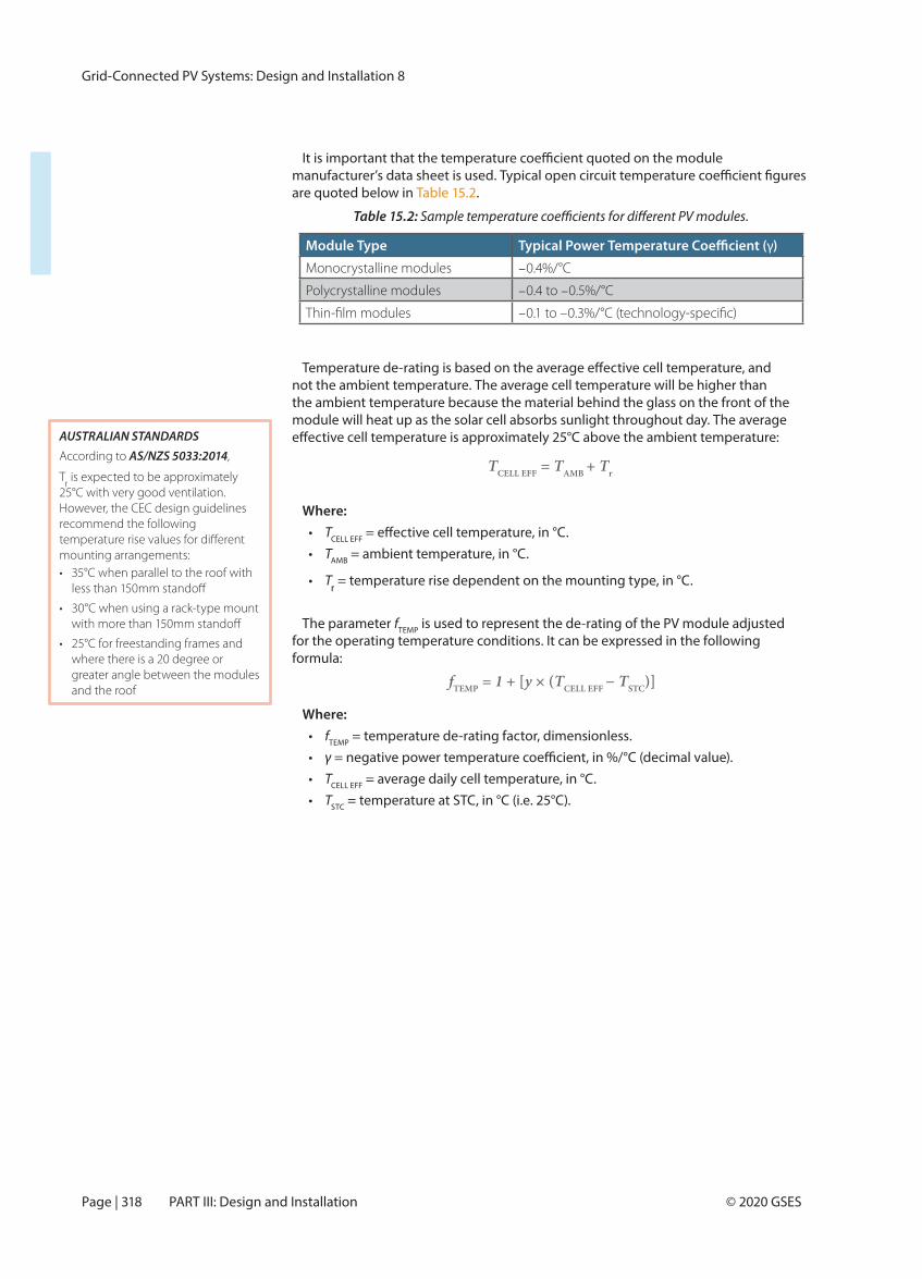
are quoted below in .
Table 15.2:
not the ambient temperature. The average cell temperature will be higher than the ambient temperature because the material behind the glass on the front of the module will heat up as the solar cell absorbs sunlight throughout day. The average
Where:• TCELL EFF
• TAMB = ambient temperature, in °C.
• Tr = temperature rise dependent on the mounting type, in °C.
The parameter fTEMP is used to represent the de-rating of the PV module adjusted for the operating temperature conditions. It can be expressed in the following formula:
Where:• fTEMP = temperature de-rating factor, dimensionless.• γ• TCELL EFF = average daily cell temperature, in °C.• TSTC = temperature at STC, in °C (i.e. 25°C).
TCELL EFF = TAMB + Tr
Module Type γ)
Monocrystalline modules –0.4%/°C
Polycrystalline modules –0.4 to –0.5%/°C
–
fTEMP = 1 + [y × (TCELL EFF − TSTC)]
AUSTRALIAN STANDARDS According to AS/NZS 5033:2014,
Tr is expected to be approximately
25°C with very good ventilation. However, the CEC design guidelines recommend the following
mounting arrangements:• 35°C when parallel to the roof with
• 30°C when using a rack-type mount
• 25°C for freestanding frames and where there is a 20 degree or greater angle between the modules and the roof
Grid-Connected PV Systems: Design and Installation 8
Page | 319© 2020 GSES
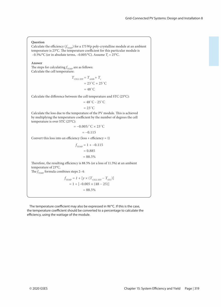
QuestionfTEMP) for a 175 Wp poly-crystalline module at an ambient
–0.5%/°C (or in absolute terms, –0.005/°C). Assume Tr = 25°C.
AnswerfTEMP are as follows:
Calculate the cell temperature:
temperature is over STC (25°C):
temperature of 23°C. fTEMP formula combines steps 2–4:
TCELL EFF = TAMB + Tr
= 23˚C + 25˚C = 48˚C
= 48˚C - 25˚C= 23˚C
= −0.005/˚C × 23˚C= −0.115
fTEMP = 1 + −0.115= 0.885= 88.5%
fTEMP = 1 + [y × (TCELL EFF − TSTC)]= 1 + [−0.005 × (48 − 25)]
= 88.5%
Grid-Connected PV Systems: Design and Installation 8
Page | 322 © 2020 GSESPART III: Design and Installation
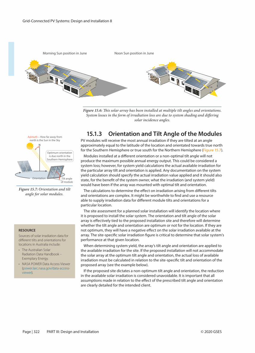
15.1.3 Orientation and Tilt Angle of the ModulesPV modules will receive the most annual irradiation if they are tilted at an angle approximately equal to the latitude of the location and orientated towards true north for the Southern Hemisphere or true south for the Northern Hemisphere ( ).
produce the maximum possible annual energy output. This could be considered a system loss; however, for system yield calculations the actual available irradiation for the particular array tilt and orientation is applied. Any documentation on the system yield calculation should specify the actual irradiation value applied and it should also
would have been if the array was mounted with optimal tilt and orientation.
particular location.The site assessment for a planned solar installation will identify the location where
it is proposed to install the solar system. The orientation and tilt angle of the solar
whether the tilt angle and orientation are optimum or not for the location. If they are
performance at that given location.When determining system yield, the array’s tilt angle and orientation are applied to
the available irradiation for the site. If the proposed installation will not accommodate the solar array at the optimum tilt angle and orientation, the actual loss of available
proposed array (see the example below).If the proposed site dictates a non-optimum tilt angle and orientation, the reduction
in the available solar irradiation is considered unavoidable. It is important that all
are clearly detailed for the intended client.
Figure 15.6:
solar incidence angles.
Figure 15.7: Orientation and tilt angle for solar modules.
Orientation
N
Optimum orientationis due north in the
Southern Hemisphere
Tilt angleof module
Azimuth – How far away fromnorth is the Sun in the Sky
RESOURCESources of solar irradiation data for
locations in Australia include:
• The Australian Solar Radiation Data Handbook – Exemplary Energy.
• NASA POWER Data Access Viewer (power.larc.nasa.gov/data-access-viewer).
Morning Sun position in June Noon Sun position in June
Grid-Connected PV Systems: Design and Installation 8
Page | 324 © 2020 GSESPART III: Design and Installation
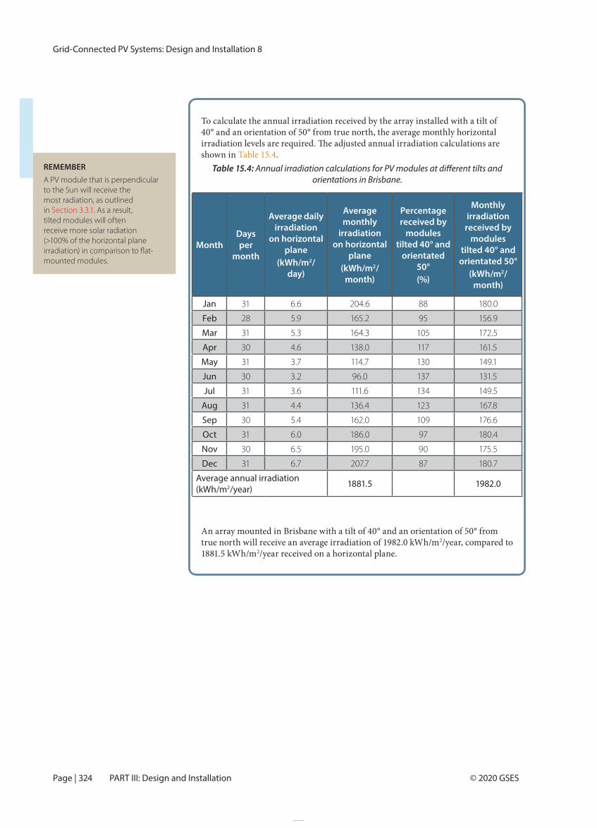
To calculate the annual irradiation received by the array installed with a tilt of 40° and an orientation of 50° from true north, the average monthly horizontal
shown in Table 15.4.Table 15.4:
orientations in Brisbane.
An array mounted in Brisbane with a tilt of 40° and an orientation of 50° from true north will receive an average irradiation of 1982.0 kWh/m2/year, compared to 1881.5 kWh/m2/year received on a horizontal plane.
REMEMBERA PV module that is perpendicular to the Sun will receive the most radiation, as outlined in . As a result, tilted modules will often receive more solar radiation (>100% of the horizontal plane
mounted modules.
MonthDays per
month
Average daily irradiation
on horizontal plane
(kWh/m2/day)
Average monthly
irradiation on horizontal
plane(kWh/m2/
month)
Percentage received by
modules tilted 40° and
orientated 50°(%)
Monthly irradiation
received by modules
tilted 40° and orientated 50°
(kWh/m2/month)
Jan 31 6.6 204.6 88 180.0
Feb 28 5.9 165.2 95 156.9
Mar 31 5.3 164.3 105 172.5
Apr 30 4.6 138.0 117 161.5
May 31 3.7 114.7 130 149.1
Jun 30 3.2 96.0 137 131.5
Jul 31 3.6 111.6 134 149.5
Aug 31 4.4 136.4 123 167.8
Sep 30 5.4 162.0 109 176.6
Oct 31 6.0 186.0 97 180.4
Nov 30 6.5 195.0 90 175.5
Dec 31 6.7 207.7 87 180.7
Average annual irradiation (kWh/m2/year) 1881.5 1982.0
Grid-Connected PV Systems: Design and Installation 8
Page | 442 © 2020 GSESPART III: Design and Installation
System yield calculations for micro-inverter systems are complex, especially if the
manually calculated (e.g. ), but some micro-inverter manufacturers provide software packages to calculate the yield. As with all systems, yield calculations should
of dirt, voltage drop/rise and any other known loss factors.
Max. inverter DC input voltage 48 V > Max. module voltage 42.56 Min. inverter operating voltage 16 V < Min. module operating voltage 24.52 V
Min. inverter start voltage 22 V < Min. module operating voltage 24.52 V (at 75°C)
However, the minimum operating voltage of the modules is not greater than the minimum operating voltage of the MPPT:Min. peak power tracking voltage 27 V > Min. module operating voltage 24.52 V
modules would be used that would always operate within the micro-inverter power point tracker range. However, for the purposes of these examples to
will be accepted.
A three-phase system using Enphase M250 micro-inverters is connected as
total of 42 module/micro-inverters in each three-phase set. For an approximate 1 MWp system, there would be 80 of these three-phase sets to give a total of
MWp.
Grid Connection
protection equipment in order to aggregate the branch circuit power to a common
boards that then feed into a main switchboard.
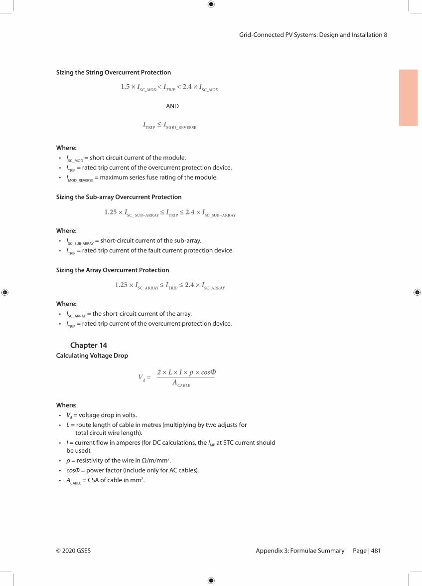
Grid-Connected PV Systems: Design and Installation 8
Page | 481© 2020 GSES
Sizing the String Overcurrent Protection
AND
Where:• ISC_MOD = short circuit current of the module.• ITRIP = rated trip current of the overcurrent protection device.• IMOD_REVERSE = maximum series fuse rating of the module.
Sizing the Sub-array Overcurrent Protection
Where: • ISC_SUB-ARRAY = short-circuit current of the sub-array.• ITRIP = rated trip current of the fault current protection device.
Sizing the Array Overcurrent Protection
Where:• ISC_ARRAY = the short-circuit current of the array.• ITRIP = rated trip current of the overcurrent protection device.
Chapter 14 Calculating Voltage Drop
Where:• Vd = voltage drop in volts.• L = route length of cable in metres (multiplying by two adjusts for
total circuit wire length).• I = current flow in amperes (for DC calculations, the IMP at STC current should
be used).• ρ = resistivity of the wire in Ω/m/mm2.• cosΦ = power factor (include only for AC cables).• ACABLE = CSA of cable in mm2.
1.5 × ISC_MOD < ITRIP < 2.4 × ISC_MOD
ITRIP ≤ IMOD_REVERSE
1.25 × ISC_ SUB−ARRAY ≤ ITRIP ≤ 2.4 × ISC_SUB−ARRAY
1.25 × ISC_ARRAY ≤ ITRIP ≤ 2.4 × ISC_ARRAY
Vd = 2 × L × I × ρ × cosΦ
ACABLE
Appendix 3: Formulae Summary
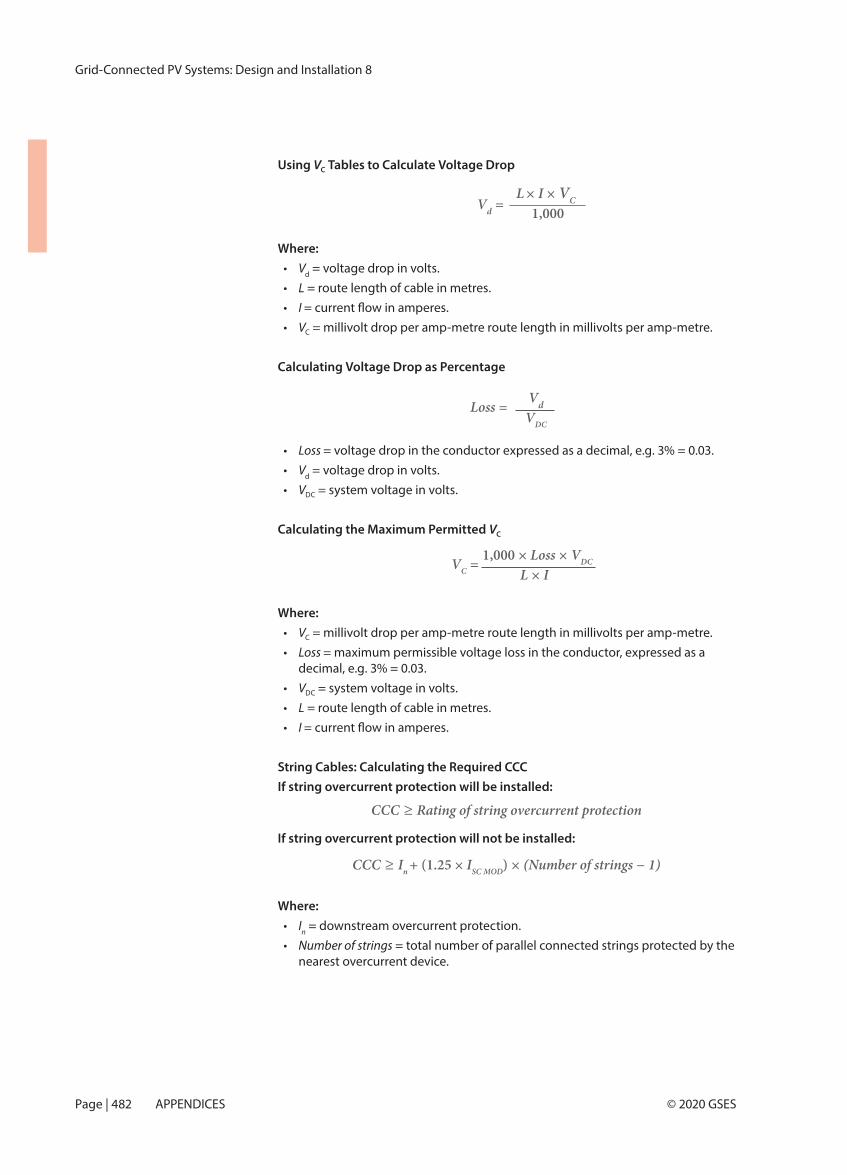
Grid-Connected PV Systems: Design and Installation 8
Page | 482 © 2020 GSESAPPENDICES
Using VC Tables to Calculate Voltage Drop
Where:• Vd = voltage drop in volts.• L = route length of cable in metres.• I • VC = millivolt drop per amp-metre route length in millivolts per amp-metre.
Calculating Voltage Drop as Percentage
• Loss = voltage drop in the conductor expressed as a decimal, e.g. 3% = 0.03.• Vd = voltage drop in volts.• VDC = system voltage in volts.
Calculating the Maximum Permitted VC
Where:• VC = millivolt drop per amp-metre route length in millivolts per amp-metre.• Loss = maximum permissible voltage loss in the conductor, expressed as a
decimal, e.g. 3% = 0.03.• VDC = system voltage in volts.• L = route length of cable in metres.• I
String Cables: Calculating the Required CCCIf string overcurrent protection will be installed:
If string overcurrent protection will not be installed:
Where:• In = downstream overcurrent protection.• Number of strings = total number of parallel connected strings protected by the
nearest overcurrent device.
Vd =L × I × VC
1,000
CCC ≥ In + (1.25 × ISC MOD) × (Number of strings − 1)
Loss = VdVDC
VC = 1,000 × Loss × VDC
L × I
CCC ≥ Rating of string overcurrent protection
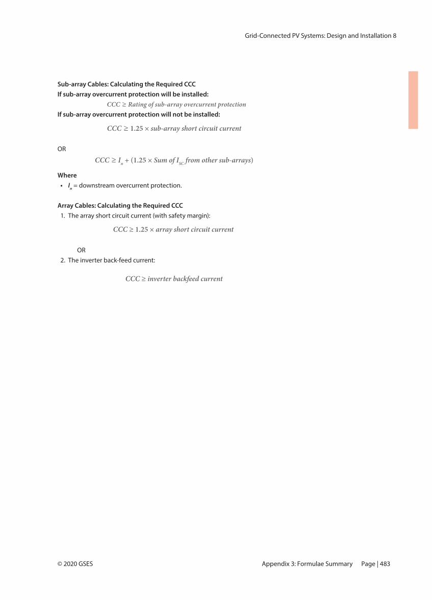
Grid-Connected PV Systems: Design and Installation 8
Page | 483© 2020 GSES
Sub-array Cables: Calculating the Required CCCIf sub-array overcurrent protection will be installed:
CCC ≥ Rating of sub-array overcurrent protectionIf sub-array overcurrent protection will not be installed:
OR
Where• In = downstream overcurrent protection.
Array Cables: Calculating the Required CCC1. The array short circuit current (with safety margin):
OR 2. The inverter back-feed current:
CCC ≥ 1.25 × sub-array short circuit current
CCC ≥ In + (1.25 × Sum of ISC from other sub-arrays)
CCC ≥ 1.25 × array short circuit current
CCC ≥ inverter backfeed current
Appendix 3: Formulae Summary
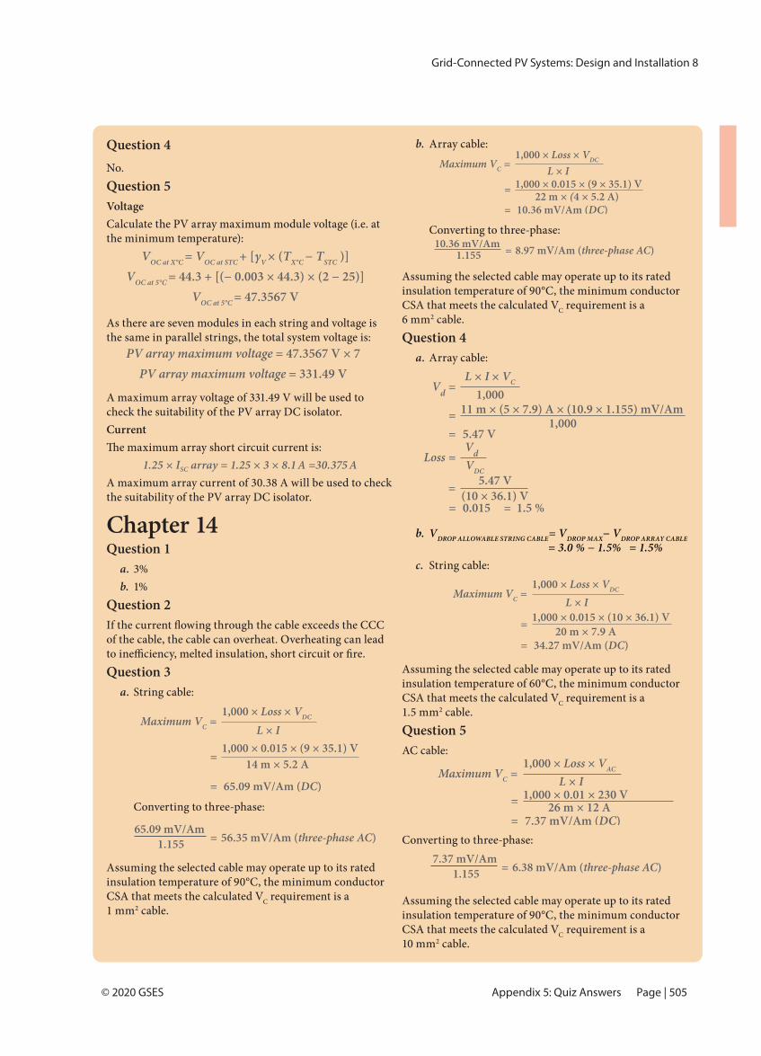
Grid-Connected PV Systems: Design and Installation 8
Page | 505© 2020 GSES
Question 4No. Question 5VoltageCalculate the PV array maximum module voltage (i.e. at the minimum temperature):
VOC at X°C = VOC at STC + [γV × (TX°C − TSTC )]VOC at 5°C = 44.3 + [(− 0.003 × 44.3) × (2 − 25)]
VOC at 5°C = 47.3567 V
As there are seven modules in each string and voltage is the same in parallel strings, the total system voltage is:
PV array maximum voltage = 47.3567 V × 7PV array maximum voltage = 331.49 V
A maximum array voltage of 331.49 V will be used to check the suitability of the PV array DC isolator.Current
1.25 × ISC array = 1.25 × 3 × 8.1 A =30.375 AA maximum array current of 30.38 A will be used to check the suitability of the PV array DC isolator.
Chapter 14Question 1
a. 3%b. 1%
Question 2
of the cable, the cable can overheat. Overheating can lead
Question 3a. String cable:
Converting to three-phase:
Assuming the selected cable may operate up to its rated insulation temperature of 90°C, the minimum conductor CSA that meets the calculated VC requirement is a
2 cable.
b. Array cable:
Converting to three-phase:
Assuming the selected cable may operate up to its rated insulation temperature of 90°C, the minimum conductor CSA that meets the calculated VC requirement is a
2 cable.Question 4
a. Array cable:
b. VDROP ALLOWABLE STRING CABLE= VDROP MAX− VDROP ARRAY CABLE
= 3.0 % − 1.5% = 1.5%c. String cable:
Assuming the selected cable may operate up to its rated insulation temperature of 60°C, the minimum conductor CSA that meets the calculated VC requirement is a
2 cable.Question 5AC cable:
Converting to three-phase:
Assuming the selected cable may operate up to its rated insulation temperature of 90°C, the minimum conductor CSA that meets the calculated VC requirement is a
2 cable.
Appendix 5: Quiz Answers
1,000 × Loss × VDCMaximum VC = L × I 1,000 × 0.015 × (9 × 35.1) V
= 14 m × 5.2 A
= 65.09 mV/Am (DC)
65.09 mV/Am 1.155 = 56.35 mV/Am (three-phase AC)
1,000 × Loss × VDCMaximum VC = L × I 1,000 × 0.015 × (9 × 35.1) V
= 22 m × (4 × 5.2 A) = 10.36 mV/Am (DC)
10.36 mV/Am 1.155 = 8.97 mV/Am (three-phase AC)
L × I × VCVd = 1,000 11 m × (5 × 7.9) A × (10.9 × 1.155) mV/Am
= 1,000 = 5.47 V
VdLoss = VDC5.47 V= (10 × 36.1) V
= 0.015 = 1.5 %
1,000 × Loss × VDCMaximum VC = L × I 1,000 × 0.015 × (10 × 36.1) V
= 20 m × 7.9 A = 34.27 mV/Am (DC)
1,000 × Loss × VACMaximum VC = L × I 1,000 × 0.01 × 230 V
= 26 m × 12 A = 7.37 mV/Am (DC)
7.37 mV/Am 1.155 = 6.38 mV/Am (three-phase AC)
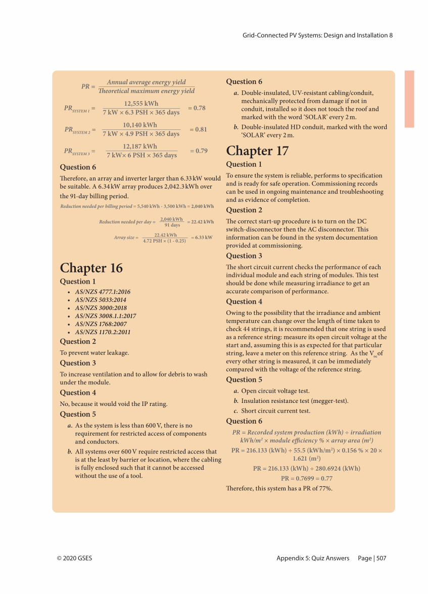
Grid-Connected PV Systems: Design and Installation 8
Page | 507© 2020 GSES
Question 6 kW would
be suitable. A 6.34 kW array produces 2,042.3 kWh over the 91-day billing period.Reduction needed per billing period = 5,540 kWh - 3,500 kWh = 2,040 kWh
Reduction needed per day = = 22.42 kWh
Array size = = 6.33 kW
2,040 kWh91 days
22.42 kWh4.72 PSH × (1 - 0.25)
Chapter 16Question 1
• AS/NZS 4777.1:2016• AS/NZS 5033:2014 • AS/NZS 3000:2018• AS/NZS 3008.1.1:2017• AS/NZS 1768:2007• AS/NZS 1170.2:2011
Question 2To prevent water leakage.Question 3To increase ventilation and to allow for debris to wash under the module.Question 4No, because it would void the IP rating.Question 5
a. As the system is less than 600 V, there is no requirement for restricted access of components and conductors.
b. All systems over 600 V require restricted access that is at the least by barrier or location, where the cabling is fully enclosed such that it cannot be accessed without the use of a tool.
Question 6a. Double-insulated, UV-resistant cabling/conduit,
mechanically protected from damage if not in conduit, installed so it does not touch the roof and marked with the word ‘SOLAR’ every 2 m.
b. Double-insulated HD conduit, marked with the word ‘SOLAR’ every 2 m.
Chapter 17Question 1
and is ready for safe operation. Commissioning records can be used in ongoing maintenance and troubleshooting and as evidence of completion.Question 2
information can be found in the system documentation provided at commissioning.Question 3
should be done while measuring irradiance to get an accurate comparison of performance.Question 4Owing to the possibility that the irradiance and ambient temperature can change over the length of time taken to check 44 strings, it is recommended that one string is used as a reference string: measure its open circuit voltage at the start and, assuming this is as expected for that particular string, leave a meter on this reference string. As the Vocof every other string is measured, it can be immediately compared with the voltage of the reference string. Question 5
a. Open circuit voltage test.b. Insulation resistance test (megger-test).c. Short circuit current test.
Question 6PR = Recorded system production (kWh) ÷ irradiation
kWh/m2 2)PR = 216.133 (kWh) ÷ 55.5 (kWh/m2) × 0.156 % × 20 ×
1.621 (m2)PR = 216.133 (kWh) ÷ 280.6924 (kWh)
PR = 0.7699 = 0.77
Appendix 5: Quiz Answers
PR =
PRSYSTEM 1 = = 0.78
PRSYSTEM 2 = = 0.81
PRSYSTEM 3 = = 0.79
12,555 kWh7 kW × 6.3 PSH × 365 days
10,140 kWh7 kW × 4.9 PSH × 365 days
12,187 kWh7 kW× 6 PSH × 365 days
Annual average energy yield
Related Documents