Rehabilitation of Bournais Wastewater Pumping Station Section 15010 Bid Opportunity No. 901-2008 MECHANICAL GENERAL PROVISIONS SMS Project No. 07-213-01 Page 1 of 9 Part 1 General 1.1 GENERAL .1 All drawings and all sections of the Specifications shall apply to and form an integral part of this section. 1.2 SCOPE OF WORK .1 Work to include all labour, Materials and equipment required for installing, testing and placing in initial operation the following systems as detailed in Specifications of each section and as shown on drawings. .1 Section 15051 Acceptable Materials & Equipment .2 Section 15180 Insulation .3 Section 15722 AHU/Ventilator .4 Section 15800 Air Distribution .5 Section 15900 Controls/Instrumentation .6 Section 15990 Testing, Adjusting and Balancing .2 All Mechanical Work to be bid as a single complete sub-contract even though Work of various mechanical trades has been further sub-divided into each Section noted above. 1.3 EXISTING CONDITIONS .1 Examine local conditions affecting Work under this contract. No allowance will be made later for necessary changes, unless notification of interferences have been brought to The Contract Administrator's attention, in writing, prior to closing of Bid Opportunity. 1.4 REGULATIONS .1 Comply with, most stringent requirements of Manitoba Building Code, National Building Code and local regulations and by-laws, with specified standards and codes and this Specification. Before any Work is proceeded with, approved layouts to be filed with and approved by proper authorities. .2 Provide necessary notices, obtain permits and pay all fees, in order that Work specified may be carried out. Charges and alterations required by authorized inspector of any authority having jurisdiction, to be carried out without charge or expense to the City. Pay all charges for service connections to municipal mains. .3 Furnish certificates confirming Work installed conforms to requirements of authorities having jurisdiction. 1.5 LIABILITY .1 Protect and maintain Work until building has been completed and accepted. Protect Work against damage during installation. Cover with tarpaulins if necessary. Repair all damage to floor and wall surfaces resulting from carrying out of Work, without expense to the City. .2 During welding or soldering ensure structure is protected against fire, shield with fire- rated sheets and galvanized iron sheets. Mount portable fire extinguishers in welding or soldering areas.

Welcome message from author
This document is posted to help you gain knowledge. Please leave a comment to let me know what you think about it! Share it to your friends and learn new things together.
Transcript
Rehabilitation of Bournais Wastewater Pumping Station Section 15010 Bid Opportunity No. 901-2008 MECHANICAL GENERAL PROVISIONS SMS Project No. 07-213-01 Page 1 of 9
Part 1 General
1.1 GENERAL
.1 All drawings and all sections of the Specifications shall apply to and form an integral part of this section.
1.2 SCOPE OF WORK
.1 Work to include all labour, Materials and equipment required for installing, testing and placing in initial operation the following systems as detailed in Specifications of each section and as shown on drawings. .1 Section 15051 Acceptable Materials & Equipment .2 Section 15180 Insulation .3 Section 15722 AHU/Ventilator .4 Section 15800 Air Distribution .5 Section 15900 Controls/Instrumentation .6 Section 15990 Testing, Adjusting and Balancing
.2 All Mechanical Work to be bid as a single complete sub-contract even though Work of various mechanical trades has been further sub-divided into each Section noted above.
1.3 EXISTING CONDITIONS
.1 Examine local conditions affecting Work under this contract. No allowance will be made later for necessary changes, unless notification of interferences have been brought to The Contract Administrator's attention, in writing, prior to closing of Bid Opportunity.
1.4 REGULATIONS
.1 Comply with, most stringent requirements of Manitoba Building Code, National Building Code and local regulations and by-laws, with specified standards and codes and this Specification. Before any Work is proceeded with, approved layouts to be filed with and approved by proper authorities.
.2 Provide necessary notices, obtain permits and pay all fees, in order that Work specified may be carried out. Charges and alterations required by authorized inspector of any authority having jurisdiction, to be carried out without charge or expense to the City. Pay all charges for service connections to municipal mains.
.3 Furnish certificates confirming Work installed conforms to requirements of authorities having jurisdiction.
1.5 LIABILITY
.1 Protect and maintain Work until building has been completed and accepted. Protect Work against damage during installation. Cover with tarpaulins if necessary. Repair all damage to floor and wall surfaces resulting from carrying out of Work, without expense to the City.
.2 During welding or soldering ensure structure is protected against fire, shield with fire-rated sheets and galvanized iron sheets. Mount portable fire extinguishers in welding or soldering areas.
Rehabilitation of Bournais Wastewater Pumping Station Section 15010 Bid Opportunity No. 901-2008 MECHANICAL GENERAL PROVISIONS SMS Project No. 07-213-01 Page 2 of 9
.3 Co-ordinate Work with other sections to avoid conflict and to ensure proper installation of all equipment. Review all contract drawings.
.4 On completion of Work, remove tools, surplus and waste Materials and leave Work in clean, perfect condition.
1.6 GUARANTEE
.1 Guarantee satisfactory operation of all work and apparatus installed under this contract. Replace, at no expense to the City, all items which fail or prove defective within a period of one year after final acceptance of complete contract by the City, always provided such failure is not due to improper usage by the City. Make good all damage to building incurred as a result of failure or repair of mechanical Work.
.2 No certification given, payment made, partial or entire use of equipment by The City, shall be construed as acceptance of defective Work or acceptance of improper Materials. Make good at once, without cost to the The City all such defective Work or Materials and consequence resulting therefrom, within one year of final acceptance date.
.3 This general guarantee shall not act as a waiver for any specified guarantee and/or warranty of greater length of time noted elsewhere in these documents.
1.7 ENGINEERING OBSERVATIONS
.1 Contractor's Work will be observed periodically by The City, and/or The Contract Administrator or their representatives, solely for purpose of determining general quality of Work, and not for any other purpose. Guidance will be offered to Contractor in interpretation of plans and Specifications to assist him to carry out Work. Observations and directives given to Contractor does not relieve Contractor and his agents, servants and employees of their responsibility to erect and install Work in all its parts in a safe and workmanlike manner, and in accordance with plans and Specifications, nor impose upon The City, and/or The Contract Administrator or their representatives, any responsibility to supervise or oversee erection or installation of any Work.
1.8 WELDING REGULATIONS
.1 Do not weld when temp. of base metal is lower than -17 deg. C except with consent of The Contract Administrator. At temperature below 0 deg. C, surface of all areas within 75mm (3") of point where weld is to be started to be heated to temp. at least warm to hand before welding is commenced. At all temperatures below +4 deg. C, operator and Work to be protected against direct effect of wind and snow.
.2 Welding shall be performed by welder holding current welder's certificate from Provincial Department of Labour.
.3 Comply with CSA W117.2 "Safety in Welding, Cutting, and Allied Processes".
1.9 MECHANICAL SHOP DRAWINGS
.1 Submit for review a minimum of six sets of detailed Shop Drawings. Refer to Section 15051 "Acceptable Materials & Equipment" for Shop Drawings requirements.
.2 Check Shop Drawings for conformity to plans and Specifications before submission.
Rehabilitation of Bournais Wastewater Pumping Station Section 15010 Bid Opportunity No. 901-2008 MECHANICAL GENERAL PROVISIONS SMS Project No. 07-213-01 Page 3 of 9
.3 Each drawing to bear a signed stamp including project name and Contractor's Firm name verifying drawings have been checked prior to submission to The Contract Administrator. Signature of stamp shall signify the contractor has checked and found all dimensions to be compatible with the Contract drawings and all capacities, quantities, sizes and other data contained in the Contract documents have been listed by the supplier on the drawings and have been checked by the undersigned and found correct.
.4 Clearly show division of responsibility. No item, equipment or description of Work shall be indicated to be supplied or Work to be done "By Others or By Purchaser". Any item, equipment or description of Work shown on Shop Drawings shall form part of Contract, unless specifically noted to contrary.
.5 Take full responsibility for securing and verifying field dimensions. In case where fabrication must proceed prior to field dimensions being available, check all Shop Drawings and approve for dimensions only. In this case guarantee that dimensions will be worked to and ensure that other sub-trades are aware of these dimensions and shall comply to them.
.6 Review by the Contract Administrator shall be mutually understood to refer to general design only. If errors in detailed dimensions or interference with Work are noticed, attention of Contractor will be called to such errors of interferences, but the Contract Administrator's review of drawings will not in any way relieve Contractor from responsibility for said errors or interferences, or from necessity of furnishing such Work, and Materials as may be required for completion of Work as called for in Contract documents.
1.10 MECHANICAL SUB-TRADES
.1 State in Bid Submission, names of all sub-trades to be used in sublet Work. Also, state extent of any Work so sublet. Request and receive The Contract Administrator's approval in writing, of all sub-trades for such Work before placing sub-trade contract.
.2 Contractor to have minimum five years experience in field of mechanical contracting and to have successfully performed Work of similar nature and approximate size to that indicated in Specifications and on drawings. Sub-trades shall employ, on this project, foremen or supervisory personnel who have had similar experience to that required of Contractor.
1.11 DRAWINGS
.1 Drawings are diagrammatic only and do not show all details. Information involving accurate measurements of building to be taken from Architectural Drawings and/or at building. Make, without additional expense to The City, all necessary changes or additions to runs to accomodate structural conditions. Locations of pipes, ducts and other equipment to be altered without charge to The City, provided change is made before installation and does not necessitate additional Materials and that all such changes are ratified by The Contract Administrator, recorded on Record Set of Drawings.
.2 Drawings and Specifications to be considered as an integral part of Contract Documents. Neither drawings nor Specifications to be used alone. Misinterpretation of requirements of plans or Specifications shall not relieve Contractor of responsibility of properly completing Work to approval of the Contract Administrator.
Rehabilitation of Bournais Wastewater Pumping Station Section 15010 Bid Opportunity No. 901-2008 MECHANICAL GENERAL PROVISIONS SMS Project No. 07-213-01 Page 4 of 9
.3 As Work progresses and before installing piping, ductwork, fixtures and equipment interfering with interior treatment and use of building, consult The Contract Administrator for comments. This applies to all levels and proper grading of piping. If Contractor fails to perform above checking and fails to inform The Contract Administrator of such interference, Contractor to bear all subsequent expense to make good the installation.
.4 Drawings indicate general location and route to be followed by pipes and ducts. Where required pipes and/or ducts are not shown on plans or only shown diagrammatically, install in such a way as to conserve head room and interfere as little as possible with free use or space through which they pass.
1.12 MATERIALS
.1 Materials and equipment specified and acceptable manufacturers are named in this Specification for the purpose of establishing the standard of Materials and workmanship to which Contractor shall adhere. Bid Submission price shall be based on the use of Materials and equipment as specified.
.2 .1 Materials of same general type to be of same manufacture (e.g. all air supply
units shall be of same manufacturer). Contractor to ensure that all sub-trades provide products of same manufacturer. .1 Follow manufacturer's recommendations for safety, adequate access for
inspection, maintenance and repairs of individual equipment installed. .2 Permit equipment maintenance and disassembly with minimum
disturbance to connecting piping and duct systems and without interference with building structure or other equipment.
.3 Provide accessible lubricating means for bearings, including permanent lubricated 'Lifetime' bearings.
.3 Contractor may propose alternate for any specified item which Contractor considers equal to that specified. Submit with Bid Opportunity complete Specifications for proposed alternate together with amount to be added to or deducted from Bid Opportunity price for consideration by The Contract Administrator. All alternate items submitted for consideration must not exceed available space limitations. All additional costs for mechanical, electrical, structural and/or architectural revisions required to incorporate Materials substituted by Contractor shall be responsibility of Contractor.
.4 Equipment listed as 'equal' in Specifications or submitted as alternate by Contractor must meet all space requirements, specified capacities and must have equipment characteristics of specified equipment as interpreted by The Contract Administrator. Install equipment in strict accordance with manufacturer's published recommendations.
.5 Equipment and Materials shown on drawings and not specified herein, or specified herein and not shown on drawings, shall be included in this Contract as though both shown and specified.
1.13 REMOVAL AND DISCONNECTION OF THE CITY'S EXISTING EQUIPMENT
.1 All mechanical equipment conflicting with new equipment being installed to be removed or disconnected by Contractor shall remain property of The City. Remove ducts and piping not required in revised systems and interfering with new installation which shall become property of Contractor.
Rehabilitation of Bournais Wastewater Pumping Station Section 15010 Bid Opportunity No. 901-2008 MECHANICAL GENERAL PROVISIONS SMS Project No. 07-213-01 Page 5 of 9
.2 Mechanical drawings indicate most mechanical equipment to be removed and/or disconnected. Mechanical equipment to be removed due to removal of walls of existing building, to be removed and pipes capped off by Contractor at no additional cost to The City.
1.14 SUPPORTS, BASES, PITS
.1 Supply and erect all special structural Work required for installation of tanks, pumps, fans, motors, duct plenums, and other apparatus.
.2 Concrete pads, concrete for floating bases, curbs and pits to be supplied under Division 3. Supply all anchor bolts, fasteners and foundation drawings. Unless noted otherwise, all major pieces of equipment such as pumps, compressors, fans, etc. to be mounted on 150mm (6") concrete pad. Refer to standard details for method of forming pump bases, etc.
.3 Mount equipment suspended above floor level but not detailed on platform bracketted from wall. Where wall thickness is inadequate to permit such brackets, carry supports to either ceiling or floor, or both as required.
1.15 FLASHING
.1 Where pipes or ducts go through a roof or wall, they should be boxed-in and flashed as per Division 3. Allow for expansion and contraction of pipe. Flashing shall be waterproof.
1.16 ACCESS DOORS
.1 Division 15 - Mechanical Subcontractor and his sub-trades to provide access doors where valves, dampers and/or any other mechanical equipment requiring access are built-in.
.2 In general terms, mechanical sub-trade responsible for supplying the valve, dampers etc. shall provide the access door required to get to the valve, damper etc.
.3 Access door to be 2.5mm (12 ga.) steel, 300mm x 450mm (12" x 18"), finished prime coat only, with concealed hinges, anchor straps, plaster lock and without screws, all equal to Milcor manufacture. Where it is necessary for persons to enter through door, doors to be at least 450mm x 600mm (18" x 24").
.4 In applied tile or exposed glaze or unglazed structural tile, access doors shall take the tile and be sized and located to suit tile patterns. In plaster ceilings, doors shall take the plaster. In masonry walls access doors to be sized and located to suit masonry unit sizes. In lay-in acoustic tile ceilings, no access doors are required, but install an approved coloured marking device in the ceiling tile below all points requiring access. Refer to Architectural Room Finish Schedule and details on architectural drawings.
.5 Supply access doors for concealed valves or groups of valves, dampers, fire dampers, flush valves, shock arrestors, trap seal primers, etc.
.6 Access doors located in fire rated ceilings and walls shall be an approved ULC stamped, fire rated door.
1.17 IDENTIFICATION OF EQUIPMENT
.1 Provide manufacturer's nameplate on each piece of equipment.
Rehabilitation of Bournais Wastewater Pumping Station Section 15010 Bid Opportunity No. 901-2008 MECHANICAL GENERAL PROVISIONS SMS Project No. 07-213-01 Page 6 of 9
.2 In addition Mechanical Contractor shall provide equipment I.D. tag minimum size 87mm x 32mm x 2.3mm (3-1/2" x 1-1/2" x 3/32") nominal thickness laminated phenolic plastic with black face and white centre. Engraved 6mm (1/4") high lettering. For motors and controls and for larger equipment such as chillers, tanks, 25mm (1") high lettering; for hot equipment such as boilers and convertors, provide engraved brass or bronze plates with black paint filled identification.
.3 Identify as follows: equipment type and number (e.g. pump no. 2), service or areas or zone building served (e.g. south zone chilled water primary).
.4 Provide manufacturers' registration plates (e.g. pressure vessel, Underwriters' Laboratories and CSA approval plates) as required by respective agency and as specified.
1.18 SCREWS, BOLTS AND FASTENERS
.1 Use standard commercial sizes and patterns with Materials and finish suitable for service.
.2 Use heavy hex heads, semi-finished unless otherwise specified. Use non-ferrous Material throughout for plumbing services. Use type 304 stainless steel for exterior areas.
.3 Bolts used on fan equipment for access to motors, bearings, filters and the like shall be heavy-duty.
.4 Bolts shall not project more than one diameter beyond nuts.
.5 Washers .1 Use plain-type washers on equipment, sheet metal and soft gaskets, lock-type
washers where vibration occurs, and resilient washers with stainless steel.
1.19 SEPARATIONS
.1 Provide firestopping for all openings in fire separations for passage of pipes, ducts, etc. to maintain integrity of fire separations.
.2 Firestopping .1 Firestopping to be appropriate product for the specific application. Submit ULC
firestopping system data sheet for review prior to proceeding. .2 Acceptable firestop system manufacters: 3M, AD Fire Protection Systems, Hilti,
Johns Mansville, and STI Specseal. .3 Components shall be ULC listed.
.3 Installation .1 Prepare all surfaces so they are clean, dry, and frost free, as per manufacturer's
published recommendations. .2 Follow manufacturer's published installation instructions precisely including field
quality control after installation. .3 Submit to The Contract Administrator, suitable document signed by
manufacturer's local representative, stating: .1 Div. 15 sub-contractor received sufficient installation instruction from
manufacturer's representative.
1.20 SAFETY DEVICE TESTING
.1 Make complete inspection of all safety devices to ensure: .1 That safety devices are complete and in accordance with Specifications and
manufacturer's recommendations.
Rehabilitation of Bournais Wastewater Pumping Station Section 15010 Bid Opportunity No. 901-2008 MECHANICAL GENERAL PROVISIONS SMS Project No. 07-213-01 Page 7 of 9
.2 That the safety devices are connected and operating according to all local regulations.
.2 On completion of inspections, supply to The Contract Administrator letters and/or certificates for their record, confirming that inspections have been completed.
1.21 RECORD DRAWINGS
.1 Provide one set of Contract prints to form Record Drawings, marked clearly with all changes and deviations from piping and ductwork, including all Contract Changes.
.2 Use different colour ink for each service.
.3 Update Record drawings on a regular basis to ensure they are accurate, and have available for reference and inspection at all times.
.4 Provide Record Drawings on CAD. Confirm version with Contract Administrator.
1.22 INSTRUCTIONS TO THE CITY'S PERSONNEL
.1 In addition to start-up supervision and instruction of The City's personnel required of individual equipment manufacturers and systems as noted, Contractor's construction supervisor to instruct The City's personnel in operation and maintenance of all equipment and systems to satisfaction of The Contract Administrator. .1 All instructions to The City's personnel shall be video taped by the Contractor. .2 This video will remain property of the The City and will be used for the sole
purpose of training and orientation of The City's maintenance staff. .3 Instruction shall include visual Materials such as drawings, diagrams, and printed
handouts. .4 Instructor(s) shall provide the necessary audio-visual equipment and other aids
necessary to convey thorough understanding of system and/or equipment operation and maintenance.
.5 Provide The City with one copy of video taped session in VHS or DVD format. The City to decide, and confirm format.
.2 Provide The City with four copies of manuals incorporating following: .1 Service instructions - including lists of spare and replacement parts and names
and addresses of suppliers. .2 Maintenance & Operating instructions. .3 Revised Shop Drawings.
.3 Forward manuals to The Contract Administrator for review. Final payment will not be made until all required manuals have been received.
.4 Review instructions with The City's representative to ensure The City's representative has a thorough understanding of equipment and its operation.
.5 Contractor shall submit to The Contract Administrator, suitable document signed by The City's representative, stating: .1 The City has received satisfactory instruction in operation and maintenance of all
equipment and systems. .2 Operation and maintenance manuals have been reviewed with The City. .3 Specified spare parts. keys, removable handles and the like, have been turned
over to The City.
Rehabilitation of Bournais Wastewater Pumping Station Section 15010 Bid Opportunity No. 901-2008 MECHANICAL GENERAL PROVISIONS SMS Project No. 07-213-01 Page 8 of 9 1.23 PAINTING
.1 Finish painting of mechanical equipment, piping, ductwork and the like shall be performed by a competent painting sub-trade of Division 15 - Mechanical.
.2 Following areas shall have equipment and Materials painted: .1 Emergency Generator Room
.3 Thoroughly clean off rust and oil, all exposed iron and steel work of every description, including hangers, pipes, ducts, etc. paint with a coat of chrome oxide phenolic base primer and a coat of 100% Alkyd base enamel of approved colour. Paint exposed galv. metal surfaces in above areas with a coat of zinc dust galvanize primer and a coat of 100% Alkyd base enamel of approved colour.
.4 Paint exposed covering in above room and areas with two coats of 100% Alkyd base enamel of approved colour.
.5 All roof top and outdoor exposed mechanical equipment, ductwork, piping, etc. shall have base prime coat and two finish coats of top-quality, exterior rubber-based paint.
.6 After piping, etc. has been painted, paint neatly stencilled letters, about 25mm (1") high, designating pipe service and arrows showing direction of flow. Wording to be as later directed by The Contract Administrator. Stencilling to occur at not more than fifty foot intervals. "Mystik" tape arrows and identification letters may be substituted, at discretion of The Contract Administrator. Stencil all pipes at access doors also.
.7 All colours shall be approved by The Contract Administrator.
1.24 IDENTIFICATION OF PIPING
.1 Division 15 shall provide mechanical pipe identification with exception that Section 09900 shall provide Primary Color painting for identification.
.2 Identify fluids in piping with Mystic markers showing name and service, including temperature and pressure where relevant, and with Mystic arrows to indicate flow direction.
.3 Apply primary colours in exposed areas only on finished piping surfaces, including secondary colour bands, to indicate type and degree of hazard.
PIPE MARKER LEGEND
VALVE TAG LEGEND
PRIMARY COLOUR
SECONDARY COLOUR
Waste water W.W. Green None
1.25 CUTTING AND PATCHING
.1 Div. 15 - Mechanical to perform all cutting only of existing surfaces as required as a result of the removal and/or relocation of existing equipment and piping and/or installation of new equipment and piping in the existing building to be included by the M.S. in the Bid Opportunity price. .1 If, in the opinion of The Contract Administrator, cutting of holes has been
improperly performed (i.e. too large for ducts or pipes) Division 15 - Mechanical
Rehabilitation of Bournais Wastewater Pumping Station Section 15010 Bid Opportunity No. 901-2008 MECHANICAL GENERAL PROVISIONS SMS Project No. 07-213-01 Page 9 of 9
to do all patching as per original Specifications and all costs will be borne by him.
1.26 SALVAGE
.1 All usable salvaged equipment and Materials shall remain the property of the The City unless specifically noted otherwise. Such Materials shall be neatly stored on Site for removal by the The City. Contractor shall remove all rejected salvage from the Site and legally dispose of it.
.2 Mechanical equipment, ductwork, and piping for mechanical systems not required in new layout to become property of Contractor. Remove Materials from Site.
.3 Mechanical drawings indicate most mechanical equipment to be removed and/or disconnected. Mechanical equipment not indicated on drawings as being removed or disconnected, but which has to be removed due to removal of walls of existing building, to be removed and pipes capped off by Contractor at no additional cost to The City.
1.27 POWER FEED TRANSFER FOR MECHANICAL EQUIPMENT
.1 The Mechanical Contractor shall be on Site to de-power and subsequently re-start the mechanical pieces of equipment which will be affected by the power transfer.
.2 For detail on the power transfer refer to Division 16 Specification.
.3 Co-ordinate with Division 16.
END OF SECTION
Rehabilitation of Bournais Wastewater Pumping Station Section 15051 Bid Opportunity No. 901-208 ACCEPTABLE MATERIALS & EQUIPMENT SMS Project No. 07-213-01 Page 1 of 1
Part 1 General
1.1 GENERAL
.1 Product noted in individual specification clauses is an item that meets specification in all respects regarding performance, quality of Materials and workmanship, and is acceptable to The Contract Administrator without qualification. Equipment proposed from other manufacturers listed as 'Approved Manufacturers' and alternates shall meet same standards.
.2 Contractor to submit within forty-eight hours of notification from The Contract Administrator, one (1) copy of fully and properly completed Appendix of Manufacturers listing thereon names of manufacturers of products which shall be used to execute Work of Contract. If list is not submitted within 48 hours, Contractor must use product named in each individual clause.
.3 Submit shop drawings for all items marked with asterisk(*).
.4 Request for equals must be received in The Contract Administrator's office no later than seven (7) working days prior to close of sub-trade Bid Opportunity.
1.2 EQUIPMENT OR MATERIAL & APPROVED MANUFACTURERS
.1 INSULATION .1 External Duct Insulation Manville; Fibreglas; Knauf .2 Fire Retardant Canvas Fattal; Radley .3 Lagging Adhesive/Coating Bakor; Childers; Fosters
.2 AIR DISTRIBUTION .1 Ducturns, damper hardware,
fan connections* Duro-Dyne .2 Duct Sealer Duro-Dyne; 3M; Flexa-Duct; United; Bakelite .3 Louvres* Airolite; Carnes; Penn; Air-O Vent; Canadian
Advanced Air; H & C; Westvent; Ventex .4 Air supply units* Ventmar
.3 CONTROLS/INSTRUMENTATION .1 Temperature control system* Honeywell; Johnson .2 Damper Actuators Belimo
END OF SECTION
Rehabilitation of bournais Wastewater Pumping Station Section 15180 Bid Opportunity No. 901-2008 INSULATION SMS Project No. 07-213-01 Page 1 of 4
Part 1 General
1.1 GENERAL
.1 All Drawings and all sections of the Specifications shall apply to and form an integral part of this section.
1.2 WORK INCLUDED
.1 Labour, Material, plant, tools, equipment and services necessary and reasonably incidental to completion of external insulation for mechanical equipment, piping, ductwork.
1.3 RELATED WORK SPECIFIED ELSEWHERE
.1 Section 15010 Mechanical General Provisions
.2 Section 15051 Acceptable Materials & Equipment
.3 Section 15722 AHU/Ventilator
.4 Section 15800 Air Distribution
Part 2 Products
2.1 MATERIALS
.1 All Materials shall be equivalent in all respects to specified products and shall be used only in applications intended by the manufacturer. Materials not specifically intended for the purpose shall not be used. Approved Materials shall not be diluted or blended with other Materials unless specifically recommended by the manufacturer of the approved Material.
.2 All final pipe and duct installations including insulation, covering and adhesive shall have a ULC Certified flame spread rating of not greater than 25, and a smoke developed classification of not more than 50.
.3 All canvas shall be treated to be fire retardant in accordance with ULC standards.
.4 Wire to be 1.2mm (18 ga.) stainless steel, dead soft annealed, type 304.
.5 U.L.C. label or satisfactory certified report from approved testing laboratory is required to indicate that fire hazard ratings for Materials proposed for use do not exceed those specified.
.6 Flameproofing treatments subject to deterioration due to effects of high humidity are not acceptable.
.7 The Contract Administrator reserves the right to demand test samples of components of insulation systems for fire hazard test rating.
Rehabilitation of bournais Wastewater Pumping Station Section 15180 Bid Opportunity No. 901-2008 INSULATION SMS Project No. 07-213-01 Page 2 of 4 2.2 COMPATIBILITY OF COMPONENTS
.1 All adhesives, sealers, vapour coating, mastics, laggings and bedding compounds, shall be compatible with Materials to which they are applied. They shall not soften, corrode, or otherwise attack such Materials in either wet or dry state and shall only be those recommended by manufacturer of insulation as suitable for application proposed. They shall be applied at ambient conditions acceptable to the manufacturer.
2.3 INSULATION CLADDING-PLUMBING
.1 Cover insulation with aluminum jacket CSA HA Series - M1980.
.2 Embossed alloy jacketting 0.4mm thick with longitudinal slip joints and 50mm end laps with factory attached protective straps with mechanical fastener.
.3 Jackets on fittings, 0.4mm thick, die shaped components of alloy with factory attached protective liner on interior surface.
.4 Location
.1 Condensate drains.
2.4 VAPOUR BARRIER RIGID INSULATION
.1 Following ducts externally insulated with Fibreglas RFFRK reinforced foil-faced vapour seal duct insulation type FF 340 g. (4.5 lb./cu.ft.) density.
.1 50mm (2") Thickness .1 All rectangular intake, exhaust and relief ducts, from wall back for a
length of 1.8m (6'-0") or from wall discharge back to damper, whichever is greater.
Part 3 Execution
3.1 WORKMANSHIP
.1 Work shall be performed by licensed journeymen.
.2 Apply insulation Materials, accessories and finishes in accordance with manufacturer's recommendations.
.3 Do not apply coverings until hydrostatic tests have been completed, surfaces are free of grease, scale, moisture, and heat tracing where required has been installed. Insulation shall be clean and dry when installed and during application of any finish.
.4 Apply insulation and coverings to equipment and piping which will operate with hot or warm liquid vapour, while surface is hot. Provide any required temporary heat to accomplish this.
.5 Cold surfaces to be dry and ferrous surfaces to be coated with rust penetrating protective paint before applying insulation and vapour barriers.
Rehabilitation of bournais Wastewater Pumping Station Section 15180 Bid Opportunity No. 901-2008 INSULATION SMS Project No. 07-213-01 Page 3 of 4
.6 Vapour barriers and insulation to be complete over full length of pipe or surface, without penetration for hangers, duct or seams, and without interruption at sleeves, pipe and fittings.
.7 Install insulation with smooth and even surfaces, with round shapes laid to true circular and concentric shape, shaped to blend with fitting insulation and adjacent covering; with full length section and tight to insulated object.
.8 Pack solid around all pipes where they pass through sleeves in walls, floor slabs, etc. for full thickness of floor with fibreglas or rockwool. Refer to firestopping clause where piping passes through fire separations. On all services, carry full insulation thickness through walls, floors, etc. Protect insulation of exposed pipes passing through floors with 1.2mm (18 ga.) galv. iron 150mm (6") from finished floor.
.9 Use pipe covering protection saddles with roll type hangers unless otherwise indicated.
.10 Butt joints
.1 Place joints on top of duct wherever practical. Butt joints on side of duct for flexible duct insulation.
.2 Adhere and seal laps of vapour barrier cover or vapour barrier strip of 100mm (4") minimum width furnished with insulation, using vapour seal adhesives.
.11 Sagging of duct insulation will not be acceptable.
.12 Stagger both longitudinal and horizontal joints, on duct insulation of multilayered construction.
.13 Duct insulation with vapour barrier shall be continuous, except at fire dampers.
.14 Protect insulation against elements during all stages of application.
.15 Do not cover manufacturer's nameplates. Cut insulation on 45 deg. angle to nameplate edge and seal.
.16 Covering to be uniform in diameter, smooth in finish. Place longitudinal seams so as to be invisible.
3.2 COLD INSULATION - PLUMBING
.1 Fibreglass
.1 Insulate flanges, fittings and valve bodies, etc.
.2 Fasten longitudinal laps with staples and seal with Swifts Adhesive #3218.
.3 Butt joints wrapped with a 100mm (4") strip of ASJ. Stagger joints on multiple layers.
.4 Refinish exposed piping with canvas and coat with Bakor 120-18 white fire retardant lagging adhesive.
.5 All fittings shall be insulated by wrapping with 25mm (1") thick layers of 340 g. (3/4 lb.) density flexible fibreglass attached with jute twine. Surface shall be wrapped with Friction Tape and sealed with and asphaltic sealing compound. Over this to be applied a smooth coating of insulating cement. Recover fittings
Rehabilitation of bournais Wastewater Pumping Station Section 15180 Bid Opportunity No. 901-2008 INSULATION SMS Project No. 07-213-01 Page 4 of 4
with ASJ vapour seal jacket and brush coat with fire retardant white lagging adhesive.
3.3 INSULATION CLADDING
.1 For aluminum jacketting installation, install in strict accordance with manufacturer's published recommendations.
3.4 VAPOR BARRIER FLEXIBLE DUCT INSULATION
.1 Rectangular Ductwork
.1 On ducts 600mm (24") wide and wider apply fasteners to bottom surface of duct by impaling on welded pins on 300mm (12") centres. Spot adhesive on 300mm (12") centres on all sides of duct. Apply insulation with edges tightly butted together and secured with 100% coverage of 3-M No. 17 or approved alternate. Staple joints and seal with 100mm (4") strips of vapor barrier foil of same quality as duct insulation membrane sealed with BF85-15.
.2 On ducts 575mm (23") wide or less insulation applied as above but welded pins may be omitted.
.2 Round Ducts
.1 Adhere to duct surface applied in strips 150mm (6") wide, 300mm (12") o.c. Butt all edges of insulation, staple and seal all joints with tape adhered over the joint. Seal all breaks with vapor barrier type.
.3 Exposed Ducts
.1 Recover ducts exposed to view with 170 g. (6 oz.) canvas secured with Bakor 120-18 white fire retardant lagging adhesive. Finish with brush coat of same adhesive.
3.5 VAPOR BARRIER RIGID DUCT INSULATION
.1 Insulation applied with edges tightly butted and secured by impaling on pins welded to duct. Pins to be staggered, minimum 300mm (12") o.c. in every direction. This applies to all sides. Secure insulation to pins with metal fasteners. Pins shall be long enough to bend after fasteners have been applied. Install two fasteners to all insulation on roof. Dab adhesive over pins and fasteners.
.2 Seal all joints, edges and breaks in vapor seal jacket with vapor barrier foil of the same quality as that of duct membrane 100mm (4") wide with BF 85-15 lagging adhesive.
.3 Exposed Ducts
.1 Recover ducts exposed to view with 170 g. (6 oz.) canvas secured with Bakor 120-18 white fire retardant lagging adhesive. Finish with brush coat of same adhesive.
END OF SECTION
Rehabilitation of Bournais Wastewater Pump Station Section 15722 Bid Opportunity No. 901-2008 AHU/Ventilator SMS Project No. 07-213-01 Page 1
PART 1 - General
1.1 GENERAL
.1 All Drawings and all sections of the specifications shall apply to and form an integral part of this section.
1.2 WORK INCLUDED
.1 Labour, Materials, plant, tools, equipment and services necessary and reasonably incidental to completion of air conditioning and/or ventilation Work.
1.3 RELATED WORK SPECIFIED ELSEWHERE
.1 Section 15010 Mechanical General Provisions
.2 Section 15180 Insulation
.3 Section 15900 Controls/Instrumentation
.4 Section 15990 Testing, Adjusting and Balancing
.5 Section 16010 Electrical General Provisions
1.4 QUALITY ASSURANCE
.1 The following shall be used as selection criteria and shall be as specified: airflow rates, external static pressures, fluid flow rates. The following are to be equaled or bettered: filter face velocities, casing leakage rates, casing and base deflection.
.2 Air handling units and major components shall be products of manufacturing firms regularly engaged in production of such equipment whose products have been in satisfactory use in similar service for not less than 10 years.
.3 Fans shall conform to AMCA bulletins regarding testing and construction and shall bear the AMCA certified rating seal for airflow and sound.
.4 Filter media shall be ULC listed, washable foam filter at intakes of exhaust air and outdoor air, and medium efficient filter at upstream of supply fan.
.5 Plate heat exchanger shall be made of aluminum; the efficiency is to be 70%.
.6 AHUs shall be CSA labelled and shall conform to Canadian Electrical Code, and Provincial and Municipal Codes.
1.5 APPROVED EQUALS
.1 The following manufacturers are approved in principle subject to meeting the specifications: MENMAR CES, Carrier.
Rehabilitation of Bournais Wastewater Pump Station Section 15722 Bid Opportunity No. 901-2008 AHU/Ventilator SMS Project No. 07-213-01 Page 2
1.6 SUBMITTALS
.1 Product data shall include dimensions, weights, capacities, certifications, component performance, electrical characteristics, casing construction details, wiring interconnections, gauges and Material finishes.
.2 The submittal shall provide all technical information relevant to the product being provided, including but not limited to, all the information shown in the schedules of this specification. It is the responsibility of the supplier to highlight any variances his equipment has with the requirements of this specification whether or not pre-approval has been obtained. Information shall be provided in the same measurement units as indicated elsewhere in this specification.
.3 The submittal shall provide fan curves [not fan tables], with specified operating points clearly plotted.
.4 The submittal shall provide filter information, including: initial APD, final APD, dust spot efficiency, final dust holding capacity, filter media description, filter frame details, and filter removal details.
.5 The manufacturer shall submit sound power levels for both air handling unit inlet, outlet and radiated at rated capacity. If the unit exceeds sound power levels at scheduled conditions, the manufacturer must provide sound attenuators and meet specified BHP.
.6 The manufacturer shall submit electrical requirements for power supply wiring including wiring diagrams for interlock and control wiring, clearly indicating factory-installed and field-installed wiring.
.7 The manufacturer shall submit the manufacturers recommended installation instructions.
.8 Omission of any of the above information will cause Shop Drawings to be immediately returned without review.
1.7 OPERATION AND MAINTENANCE DATA
.1 The manufacturer shall submit operation and maintenance data.
.2 The manufacturer shall include instructions for lubrication, filter replacement, motor and drive replacement, and spare parts lists.
1.8 DELIVERY, STORAGE, AND HANDLING
.1 The manufacturer shall deliver products to Site on factory-installed base rail or shipping skid and ship units by truck with 10 mil poly shrink-wrap.
Rehabilitation of Bournais Wastewater Pump Station Section 15722 Bid Opportunity No. 901-2008 AHU/Ventilator SMS Project No. 07-213-01 Page 3
1.9 ENVIRONMENTAL REQUIREMENTS
.1 Units shall not be operated for any purpose, temporary or permanent, until ductwork is clean, filters are in place, bearings lubricated, and the fan has been test run under observation.
1.10 SPARE PARTS
.1 The manufacturer shall provide one complete spare set of filters and belts.
PART 2 - PRODUCTS
2.1 GENERAL
.1 The manufacturer shall provide the packaged air handling unit in configuration as indicated on the Drawings in this Bid Opportunity package. The unit shall include all specified components installed at the factory. Field fabrication of units and their components will not be accepted.
.2 Supply one “VENMAR CES” ventilator, model HRV600i, provide with supply and exhaust fan, aluminum plate heat exchanger and recirculation defrost option. The capacity is to be 189 L/s (400 CFM) @ 125 Pa (0.75” W.G.) ESP.
2.2 CASING
.1 Walls shall be constructed of 16 gauge galvanized steel. The inner liner shall be 18 gauge washdown galvanized steel. Insulation shall be 50 mm thick 4.5 lb. density fiberglass with a neoprene liner to seal the insulation. All permanently joined flanged panel surfaces shall be sealed with an individual strip of 1/8” x 3/8” tape sealer for high pressure construction. Wall and roof seams shall be turned inward to provide a clean flush exterior finish. All panel seams shall be sealed during assembly to produce an airtight unit.
.2 The internal liner shall be suitable for washing with a pressure washer or steam cleaner without risk of wetting the insulation. The liner shall be installed over top of the panel flanges and each liner seam shall be sealed with a lap joint. The wall liner shall be installed over top of the base water dam such that any water run-off from the liner will drip into the water tight base rather than into the wall panel. The roof liner shall be installed over top of the roof support so that water cannot enter the roof insulation.
.3 All panels shall be joined on 200mm centers using cadmium plated TEK screws.
.4 All insulation edges shall be protected with metal lagging. Insulation systems using stickpins or adhesives are not acceptable.
Rehabilitation of Bournais Wastewater Pump Station Section 15722 Bid Opportunity No. 901-2008 AHU/Ventilator SMS Project No. 07-213-01 Page 4
.5 Stiffeners of angle steel shall be supplied as required to maintain casing deflection criteria of 1/200 at 1.5 times the working pressure. If panels cannot meet this deflection, an additional internal reinforcing shall be added.
.6 Acoustical Performance:
.1 The housing shall have been tested for acoustical performance by an accredited independent laboratory.
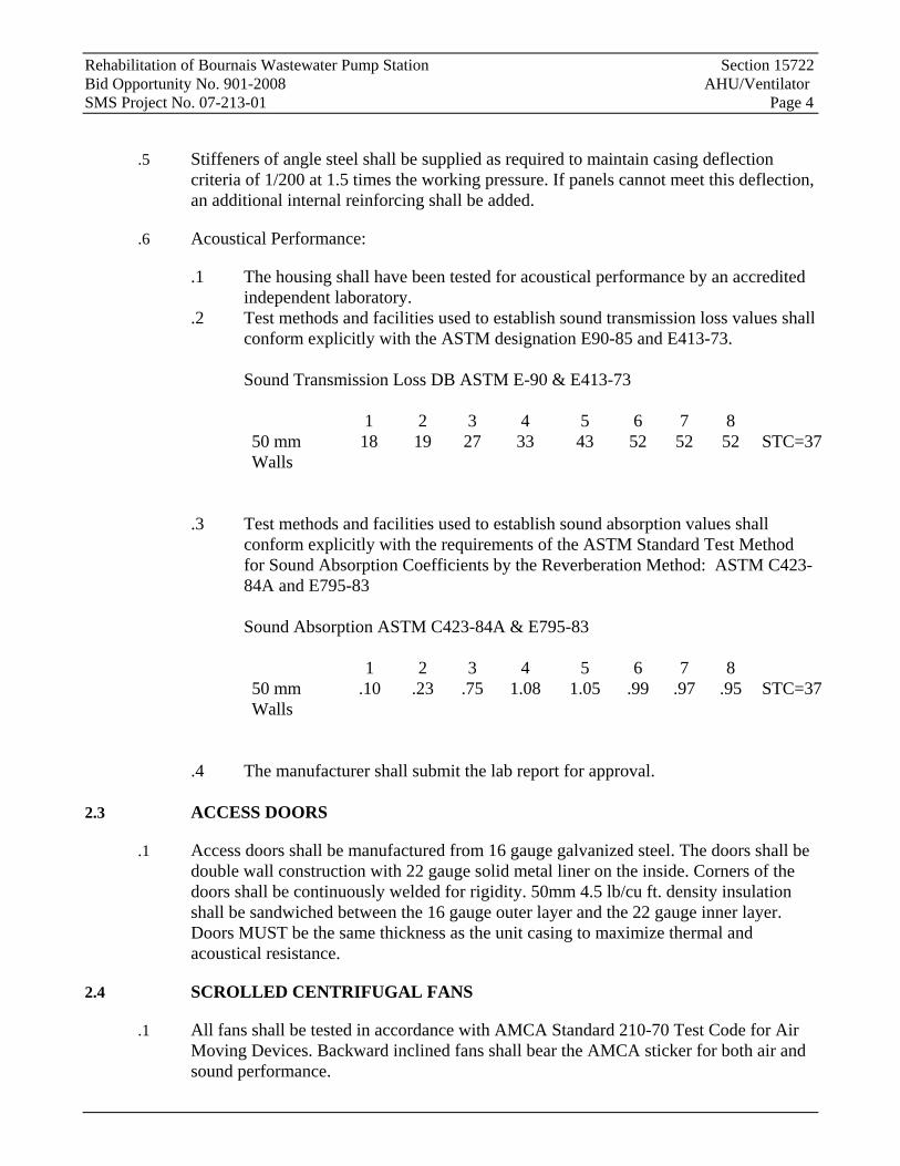
.2 Test methods and facilities used to establish sound transmission loss values shall conform explicitly with the ASTM designation E90-85 and E413-73. Sound Transmission Loss DB ASTM E-90 & E413-73 1 2 3 4 5 6 7 8 50 mm Walls
18 19 27 33 43 52 52 52 STC=37
.3 Test methods and facilities used to establish sound absorption values shall conform explicitly with the requirements of the ASTM Standard Test Method for Sound Absorption Coefficients by the Reverberation Method: ASTM C423-84A and E795-83
Sound Absorption ASTM C423-84A & E795-83 1 2 3 4 5 6 7 8 50 mm Walls
.10 .23 .75 1.08 1.05 .99 .97 .95 STC=37
.4 The manufacturer shall submit the lab report for approval.
2.3 ACCESS DOORS
.1 Access doors shall be manufactured from 16 gauge galvanized steel. The doors shall be double wall construction with 22 gauge solid metal liner on the inside. Corners of the doors shall be continuously welded for rigidity. 50mm 4.5 lb/cu ft. density insulation shall be sandwiched between the 16 gauge outer layer and the 22 gauge inner layer. Doors MUST be the same thickness as the unit casing to maximize thermal and acoustical resistance.
2.4 SCROLLED CENTRIFUGAL FANS
.1 All fans shall be tested in accordance with AMCA Standard 210-70 Test Code for Air Moving Devices. Backward inclined fans shall bear the AMCA sticker for both air and sound performance.
Rehabilitation of Bournais Wastewater Pump Station Section 15722 Bid Opportunity No. 901-2008 AHU/Ventilator SMS Project No. 07-213-01 Page 5
.2 Fan housing shall be constructed of steel, adequately braced with structural steel for rigidity.
.3 Fan shafts shall be of solid, ground and polished, carbon steel, SAE 1045 material, machined to close tolerances, keyed to the fan wheel. The fan shaft shall be coated with a rust inhibitor after machining. Hollow shafts will not be acceptable.
.4 Fan bearings shall be in self aligning pillow block, grease lubricated, extra heavy duty anti-friction ball or spherical roller type, selected for an average life of L50 200,000 hours at design operating conditions. Bearings are to be mounted on the fan structural bracing.
.5 The entire fan assembly to be factory tested and dynamically balanced to not exceed 2.5 mm per second velocity as measured on IRD or PMC analyzer. The outlet of the fan shall be separated from the unit casing by means of a factory installed flexible fabric connection. The internally mounted motor shall be provided on a slide rail base to allow proper adjustment of belt tension.
.6 Fans shall have inlet OSHA approved inlet screens.
2.5 MOTORS AND DRIVES
.1 Fan motors shall be mounted and isolated on the same integral base as the fan.
.2 The v-belt drive shall have a variable pitch sheave for motors less than 7.5 hp and a constant pitch sheave for motors of 7.5 or greater hp rated at 1.2 times the motor nameplate.
2.6 AIR LEAKAGE TESTING
.1 The unit manufacturer shall factory pressure test each air handling unit to ensure the leakage rate of the casing does not exceed 49 l/s to a maximum of 1.0% of the unit air flow when tested at 2490 kPa. The leakage test shall be performed with humidifier panels installed.
.2 The test shall be conducted in accordance with SMACNA duct construction manual. A calibrated orifice shall be used to measure leakage airflow.
.3 An officer of the manufacturing company shall certify test results and forward copies of the certified test results to the Contract Administrator. The Contract Administrator shall witness the pressure test on the first unit. The manufacturer shall provide transportation for the Contract Administrator and the City to the factory.
.4 Positive pressure plenums shall be tested positively and negative pressure plenums shall be tested negatively.
Rehabilitation of Bournais Wastewater Pump Station Section 15722 Bid Opportunity No. 901-2008 AHU/Ventilator SMS Project No. 07-213-01 Page 6
2.7 DRAINS
.1 The manufacturer shall provide 25mm capped floor drain connections on the side of the unit for complete drainability of the base pan for AHU. Capped shall be removable in the event that internal unit wash down takes place, the caps can easily be removed for draining.
2.8 WARRANTY
.1 Manufacturer/Supplier shall include for parts and labour warranty on all components for a period of one year from start-up or 18 months from shipment, whichever is sooner.
PART 3 - EXECUTION
3.1 GENERAL
.1 Start-up of unit shall be executed by manufacturer’s personnel. A complete manufacturer’s check list of field start-up tests must be submitted with operations and maintenance instructions, and shall be signed by start-up technician and mechanical trade, field supervisor as certified satisfactory for operation.
.2 Complete AHU factory installation relating to mechanical and or electrical Materials, piping, pipe insulation, wiring, etc. shall conform to standards set out in Division 15 and Division 16 Specification.
END OF SECTION
Rehabilitation of Bournais Wastewater Pumping Station Section 15800 Bid Opportunity No. 901-2008 AIR DISTRIBUTION SMS Project No. 07-213-01 Page 1 of 8
Part 1 General
1.1 GENERAL
.1 All Drawings and all sections of the Specifications shall apply to and form an integral part of this section.
1.2 WORK INCLUDED
.1 Labour, Materials, plant, tools, equipment and services necessary and reasonably incidental to completion of air conditioning and/or ventilation Work.
1.3 RELATED WORK SPECIFIED ELSEWHERE
.1 Section 15010 Mechanical General Provisions
.2 Section 15180 Insulation
.3 Section 15722 AHU/Ventilator
.4 Section 15900 Controls/Instrumentation
.5 Section 15990 Testing, Adjusting and Balancing
.6 Section 16010 Electrical General Provisions
Part 2 Products
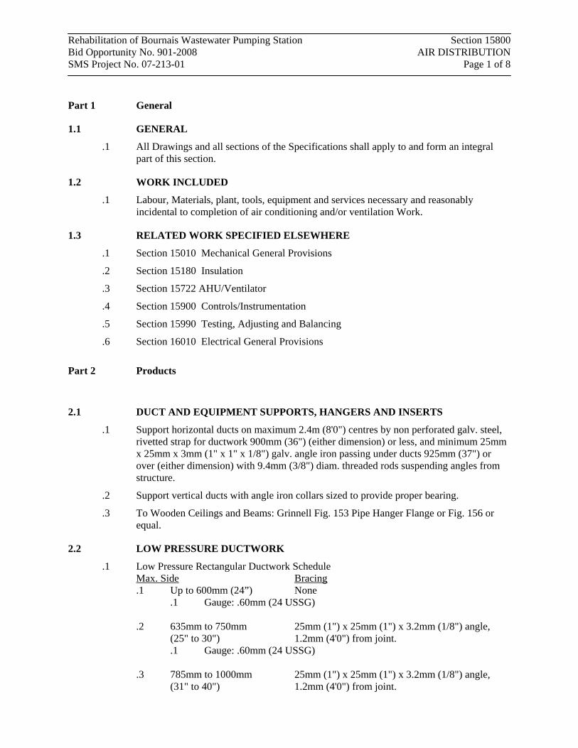
2.1 DUCT AND EQUIPMENT SUPPORTS, HANGERS AND INSERTS
.1 Support horizontal ducts on maximum 2.4m (8'0") centres by non perforated galv. steel, rivetted strap for ductwork 900mm (36") (either dimension) or less, and minimum 25mm x 25mm x 3mm (1" x 1" x 1/8") galv. angle iron passing under ducts 925mm (37") or over (either dimension) with 9.4mm (3/8") diam. threaded rods suspending angles from structure.
.2 Support vertical ducts with angle iron collars sized to provide proper bearing.
.3 To Wooden Ceilings and Beams: Grinnell Fig. 153 Pipe Hanger Flange or Fig. 156 or equal.
2.2 LOW PRESSURE DUCTWORK
.1 Low Pressure Rectangular Ductwork Schedule Max. Side Bracing .1 Up to 600mm (24”) None
.1 Gauge: .60mm (24 USSG) .2 635mm to 750mm
(25" to 30") 25mm (1") x 25mm (1") x 3.2mm (1/8") angle, 1.2mm (4'0") from joint.
.1 Gauge: .60mm (24 USSG) .3 785mm to 1000mm
(31" to 40") 25mm (1") x 25mm (1") x 3.2mm (1/8") angle, 1.2mm (4'0") from joint.
Rehabilitation of Bournais Wastewater Pumping Station Section 15800 Bid Opportunity No. 901-2008 AIR DISTRIBUTION SMS Project No. 07-213-01 Page 2 of 8
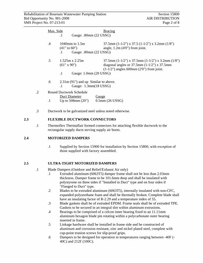
Max. Side Bracing .1 Gauge: .80mm (22 USSG)
.4 1040mm to 1.5m
(41" to 60") 37.5mm (1-1/2") x 37.5 (1-1/2") x 3.2mm (1/8") angle, 1.2m (4'0") from joint.
.1 Gauge: .80mm (22 USSG) .5 1.525m x 2.25m
(61" x 90") 37.5mm (1-1/2") x 37.5mm (1-1/2") x 3.2mm (1/8") diagonal angles or 37.5mm (1-1/2") x 37.5mm (1-1/2") angles 600mm (2'0") from joint.
.1 Gauge: 1.0mm (20 USSG) .6 2.31m (91") and up Similar to above.
.1 Gauge: 1.3mm(18 USSG)
.2 Round Ductwork Schedule Duct Diameter Gauge
.1 Up to 508mm (20") 0.5mm (26 USSG)
.3 Ductwork to be galvanized steel unless noted otherwise.
2.3 FLEXIBLE DUCTWORK CONNECTORS
.1 Thermoflex Thermaflair formed connectors for attaching flexible ductwork to the rectangular supply ducts serving supply air boots.
2.4 MOTORIZED DAMPERS
.1 Supplied by Section 15900 for installation by Section 15800, with exception of those supplied with factory assembled.
2.5 ULTRA-TIGHT MOTORIZED DAMPERS
.1 Blade Dampers (Outdoor and Relief/Exhaust Air only) .1 Extruded aluminum (6063T5) damper frame shall not be less than 2.03mm
thickness. Damper frame to be 101.6mm deep and shall be insulated with polystyrene on three sides if "Installed in Duct" type and on four sides if "Flanged to Duct" type.
.2 Blades to be extruded aluminum (6063T5), internally insulated with non-CFC, expanded polyurethane foam and shall be thermally broken. Complete blade shall have an insulating factor of R-2.29 and a temperature index of 55.
.3 Blade gaskets shall be of extruded EPDM. Frame seals shall be of extruded TPE. Gaskets to be secured in an integral slot within aluminum extrusions.
.4 Bearings to be comprised of a celcon inner bearing fixed to an 11.11mm aluminum hexagon blade pin rotating within a polycarbonate outer bearing inserted in frame.
.5 Linkage hardware shall be installed in frame side and be constructed of aluminum and corrosion resistant, zinc and nickel plated steel, complete with cup-point trunion screws for slip-proof grips.
.6 Dampers to be designed for operation in temperatures ranging between -40F (-40C) and 212F (100C).
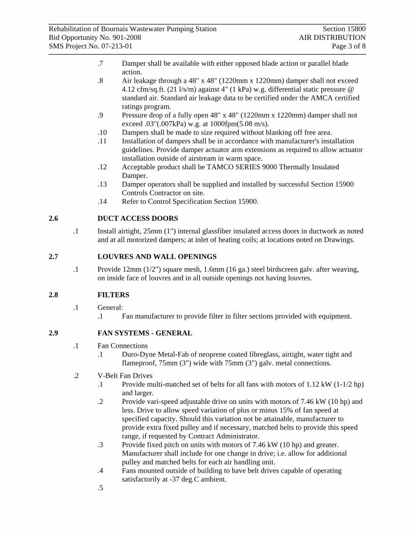
Rehabilitation of Bournais Wastewater Pumping Station Section 15800 Bid Opportunity No. 901-2008 AIR DISTRIBUTION SMS Project No. 07-213-01 Page 3 of 8
.7 Damper shall be available with either opposed blade action or parallel blade action.
.8 Air leakage through a 48" x 48" (1220mm x 1220mm) damper shall not exceed 4.12 cfm/sq.ft. (21 l/s/m) against 4" (1 kPa) w.g. differential static pressure @ standard air. Standard air leakage data to be certified under the AMCA certified ratings program.
.9 Pressure drop of a fully open 48" x 48" (1220mm x 1220mm) damper shall not exceed .03"(.007kPa) w.g. at 1000fpm(5.08 m/s).
.10 Dampers shall be made to size required without blanking off free area.
.11 Installation of dampers shall be in accordance with manufacturer's installation guidelines. Provide damper actuator arm extensions as required to allow actuator installation outside of airstream in warm space.
.12 Acceptable product shall be TAMCO SERIES 9000 Thermally Insulated Damper.
.13 Damper operators shall be supplied and installed by successful Section 15900 Controls Contractor on site.
.14 Refer to Control Specification Section 15900.
2.6 DUCT ACCESS DOORS
.1 Install airtight, 25mm (1") internal glassfiber insulated access doors in ductwork as noted and at all motorized dampers; at inlet of heating coils; at locations noted on Drawings.
2.7 LOUVRES AND WALL OPENINGS
.1 Provide 12mm (1/2") square mesh, 1.6mm (16 ga.) steel birdscreen galv. after weaving, on inside face of louvres and in all outside openings not having louvres.
2.8 FILTERS
.1 General: .1 Fan manufacturer to provide filter in filter sections provided with equipment.
2.9 FAN SYSTEMS - GENERAL
.1 Fan Connections .1 Duro-Dyne Metal-Fab of neoprene coated fibreglass, airtight, water tight and
flameproof, 75mm (3") wide with 75mm (3") galv. metal connections.
.2 V-Belt Fan Drives .1 Provide multi-matched set of belts for all fans with motors of 1.12 kW (1-1/2 hp)
and larger. .2 Provide vari-speed adjustable drive on units with motors of 7.46 kW (10 hp) and
less. Drive to allow speed variation of plus or minus 15% of fan speed at specified capacity. Should this variation not be attainable, manufacturer to provide extra fixed pulley and if necessary, matched belts to provide this speed range, if requested by Contract Administrator.
.3 Provide fixed pitch on units with motors of 7.46 kW (10 hp) and greater. Manufacturer shall include for one change in drive; i.e. allow for additional pulley and matched belts for each air handling unit.
.4 Fans mounted outside of building to have belt drives capable of operating satisfactorily at -37 deg.C ambient.
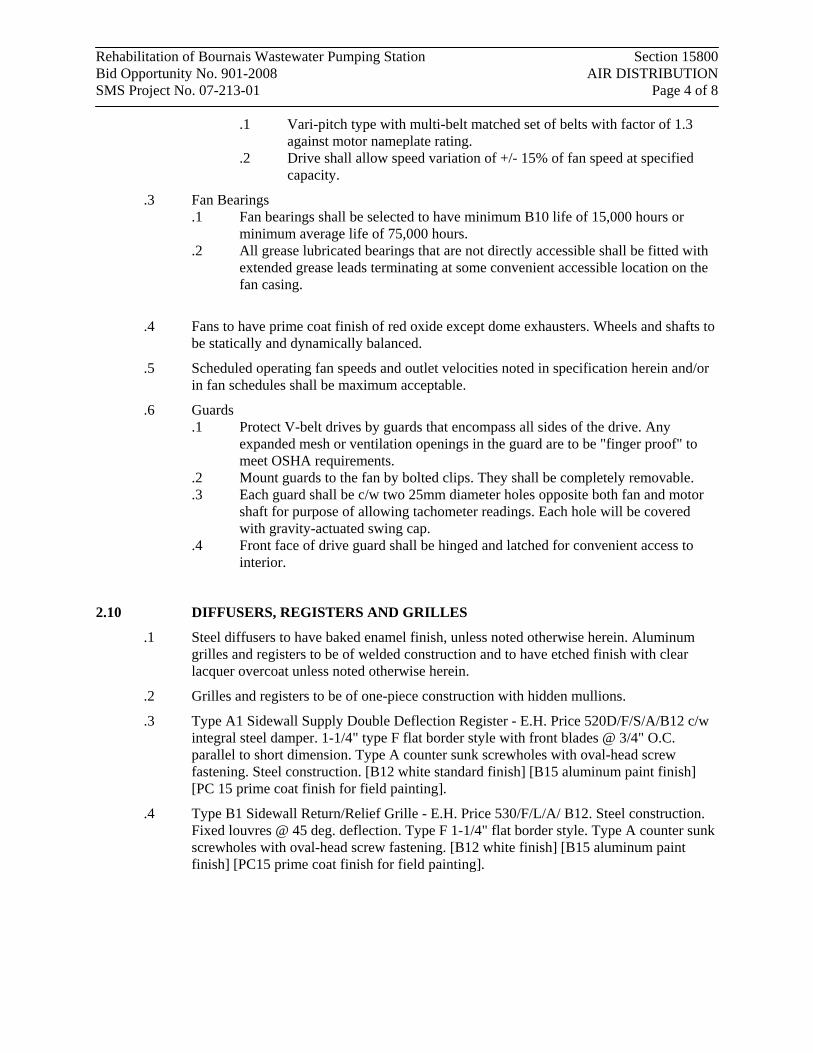
.5
Rehabilitation of Bournais Wastewater Pumping Station Section 15800 Bid Opportunity No. 901-2008 AIR DISTRIBUTION SMS Project No. 07-213-01 Page 4 of 8
.1 Vari-pitch type with multi-belt matched set of belts with factor of 1.3 against motor nameplate rating.
.2 Drive shall allow speed variation of +/- 15% of fan speed at specified capacity.
.3 Fan Bearings .1 Fan bearings shall be selected to have minimum B10 life of 15,000 hours or
minimum average life of 75,000 hours. .2 All grease lubricated bearings that are not directly accessible shall be fitted with
extended grease leads terminating at some convenient accessible location on the fan casing.
.4 Fans to have prime coat finish of red oxide except dome exhausters. Wheels and shafts to be statically and dynamically balanced.
.5 Scheduled operating fan speeds and outlet velocities noted in specification herein and/or in fan schedules shall be maximum acceptable.
.6 Guards .1 Protect V-belt drives by guards that encompass all sides of the drive. Any
expanded mesh or ventilation openings in the guard are to be "finger proof" to meet OSHA requirements.
.2 Mount guards to the fan by bolted clips. They shall be completely removable.
.3 Each guard shall be c/w two 25mm diameter holes opposite both fan and motor shaft for purpose of allowing tachometer readings. Each hole will be covered with gravity-actuated swing cap.
.4 Front face of drive guard shall be hinged and latched for convenient access to interior.
2.10 DIFFUSERS, REGISTERS AND GRILLES
.1 Steel diffusers to have baked enamel finish, unless noted otherwise herein. Aluminum grilles and registers to be of welded construction and to have etched finish with clear lacquer overcoat unless noted otherwise herein.
.2 Grilles and registers to be of one-piece construction with hidden mullions.
.3 Type A1 Sidewall Supply Double Deflection Register - E.H. Price 520D/F/S/A/B12 c/w integral steel damper. 1-1/4" type F flat border style with front blades @ 3/4" O.C. parallel to short dimension. Type A counter sunk screwholes with oval-head screw fastening. Steel construction. [B12 white standard finish] [B15 aluminum paint finish] [PC 15 prime coat finish for field painting].
.4 Type B1 Sidewall Return/Relief Grille - E.H. Price 530/F/L/A/ B12. Steel construction. Fixed louvres @ 45 deg. deflection. Type F 1-1/4" flat border style. Type A counter sunk screwholes with oval-head screw fastening. [B12 white finish] [B15 aluminum paint finish] [PC15 prime coat finish for field painting].
Rehabilitation of Bournais Wastewater Pumping Station Section 15800 Bid Opportunity No. 901-2008 AIR DISTRIBUTION SMS Project No. 07-213-01 Page 5 of 8 2.11 ELECTRIC DUCT HEATERS
.1 Thermolec Model SC electric duct heaters where noted, open coil element supported refractory porcelain insulators. 1.2mm (18 ga.) galv. steel frame flanged manual reset high limit controllers. Insertion-type coil to slide out duct side. Airtight sheet metal channel around coil. Fit with CSA approved protection inlet screen.
.2 Equip with both automatic recycling and manual reset type high temperature limit thermostats. Heaters to be CSA approved. Minimum air velocities to conform to manufacturers minimum requirements.
.3 Watt density not to exceed 242 kw/sq.m (22.5 KW per sq. ft.).
.4 Coils located outdoors to have weatherproof construction.
.5 EHC-01 to be mounted in ductwork of 350mm (W) x200mm (H) and shall have 5kw heating capacity at 600v/3ph/3w. Refer to mechanical drawing M2.0 for location.
Part 3 Execution
3.1 DUCT OPENINGS
.1 Locate only openings in walls, floors, partitions, beams, etc. required for ducts, equipment, etc. Contractor to form all openings for same, except as noted below.
3.2 DUCT AND EQUIPMENT SUPPORTS, HANGERS AND INSERTS
.1 Design, Installation .1 Supports to secure ducts and equipment, prevent vibration and provide for
expansion and contraction. Design supports of strength and rigidity in a manner which will not stress the building construction. Use inserts for suspending hangers. Do not use vertical expansion shields without The Contract Administrator's approval.
.2 Concrete Inserts (where applicable) .1 Do not weaken concrete or penetrate waterproofing membrane. Use reinforcing
rods through inserts for pipe sizes over 50mm (2"), or equivalent weight. Where concrete slab is finished ceiling, inserts to be flush with surface.
.3 Protect insulation at contact with hangers and support with approved metal shields.
3.3 CO-ORDINATION WITH H.V.A.C. BALANCE AND TESTING AGENCY
.1 Refer to Section 15990 H.V.A.C. Balance and Testing. Co-ordinate work with Section 15990.
.2 As a part of this contract, Section 15800 shall make any changes in pulleys and belts, and add manual dampers for correct balance as recommended by 15990, at no additional cost to the City.
.3 Section 15800 responsible for initial alignment and tension of all fan pulleys and belts, of equipment supplied by Section 15800.
3.4 LOW PRESSURE DUCTWORK
.1 Where duct width exceeds 450mm (18") in largest dimension, stiffen by cross breaking sheets diagonally. Beaded ducts as per SMACNA Catalogue Fig. 1.13 acceptable alternative.
Rehabilitation of Bournais Wastewater Pumping Station Section 15800 Bid Opportunity No. 901-2008 AIR DISTRIBUTION SMS Project No. 07-213-01 Page 6 of 8
.2 Duct sizes are inside dimensions. If ducts are acoustically lined, outside duct size to be increased as required.
.3 Single thickness partitions between ducts not accepted. .1 All ductwork shall have seams and joints sealed watertight with Duro-Dyne S-2
duct sealer and FT-2 fibreglass duct tape. Prior to installation ductwork to be clean, dry and free of grease. Apply duct sealer with stiff brush or trowel. Wrap wet seam or joint with duct tape and apply further coat of duct sealer. Duct sealer and glassfiber to extend 25mm (1") on each side of joint or seam. On outside ductwork construct duct so that top of duct slopes 12mm (1/2") per 300mm (12") minimum to ensure that water does not collect on top.
.2 Ductwork exposed in finished rooms do not require duct tape application, but seams and joints shall be sealed with S-2 duct sealer. Sealer must be capable of accepting finish painting.
.3 Ductwork on roof shall have seams and joints sealed by application of TREMCO MONO black acrylic sealant applied with application gun and levelled with putty knife. Materials shall be used in accordance with manufacturer's printed recommendations.
.4 Provide openings for thermostats and controllers by Section 15900.
.5 Where ductwork conflicts with mechanical and electrical piping and it is not possible to divert ductwork or piping to stay within allowable space limitations, provide duct easements. Easements not required on pipes 100mm (4") and smaller outside dimension, unless this exceeds 20% duct area. Irregular or flat shaped piping requires duct easement. Hangers and stays in ductwork to be parallel to air flow. If easement exceeds 20% of duct area, duct to be split into two ducts with original duct area being maintained. Easements to be approved by The Contract Administrator before installation.
.6 If ductwork is not adequately braced and/or supported to provide good installation, additional bracing and/or supports to be provided at no extra cost to The City. The Contract Administrator to interpret.
.7 Assemble round duct sections using beaded couplings attached with sheet metal screws.
3.5 FLEXIBLE DUCTWORK CONNECTORS
.1 Mount on ducts with mastic seal and sheet metal screws. Formed conical connections approved by The Contract Administrator, to be considered equal.
3.6 MOTORIZED DAMPERS
.1 Units in acoustically lined ducts are to be sized to suit clear dimensions of acoustic insulation and not of size to suit sheet metal duct. Where units are located in acoustic lined ducting, install heavy gauge metal channel and fasten to metal duct to receive damper frame. Space between channel and duct to be filled with flexible insulation.
.2 On plenums and ducts with external insulation, Section 15900 to provide channel mounting frame of same thickness as insulation. Pack channel frame with loose fibreglass insulation.
Rehabilitation of Bournais Wastewater Pumping Station Section 15800 Bid Opportunity No. 901-2008 AIR DISTRIBUTION SMS Project No. 07-213-01 Page 7 of 8 3.7 LOUVRES AND WALL OPENINGS
.1 Flash and make all openings around the louvres and wall openings weathertight. Slope ductwork down to louvre. Drill drain holes in bottom blade of louvre. Seal ductwork with Duro-Dyne S-2 until watertight.
3.8 FILTERS
.1 During construction period, no air system to be started unless air filters function as specified. At time of building acceptance by the City, all filter banks to be in perfectly clean operating condition. There shall be no air bypass around or in filter banks.
.2 Install all filters as per mfg. published installation data.
3.9 FAN SYSTEMS - GENERAL
.1 Use flexible connections at inlets and outlets where ductwork and plenums connect to fans and air-handling equipment.
.2 Fan Vibration Isolation .1 Fan manufacturer to submit necessary information for proper isolation selection.
This information to be incorporated in shop drawings and shall include fan sizes, fan speeds, equipment weights, etc.
.3 Fan Vibration Isolation .1 Install as per Isolation manufacturer's published data.
.4 All equipment shall be installed in strict accordance with manufacturer's published data.
.5 Protection of Fan Equipment Before Installation .1 Grease shafts, sheaves, etc. to prevent corrosion. Fan bearings to be greased or
oiled at time of building takeover.
.6 Centrifugal fans located outdoors to have drain holes in casing.
.7 Co-ordinate installation of smoke detectors with Division 16 - Electrical.
3.10 TESTING OF DUCTWORK
.1 Visually and audibly check for air leaks that can be heard or felt under normal operating conditions. Repair all leaks in ductwork.
3.11 CLEANING OF H.V.A.C. SYSTEMS
.1 Ensure electrical power supply to air handling equipment, fans, etc. is locked out and tagged prior to commencement of work. Maintain the system lockout intact and ensure the system is not-restarted or operated until work completed.
.2 Segregate points where access to fan chambers, plenums, larger diameter ducting, etc. will be made from adjacent work or Occupied Areas by closing doors, placing of barricades or tape barriers, etc.
.3 Provide polyethylene drop sheet beneath and adjacent to all points where access to air handling equipment, ducting, plenums, etc. will be made.
.4 Provide and post required signage at all points where personnel access to air handling equipment, ducting, plenums, etc. is possible.
Rehabilitation of Bournais Wastewater Pumping Station Section 15800 Bid Opportunity No. 901-2008 AIR DISTRIBUTION SMS Project No. 07-213-01 Page 8 of 8
.5 Seal openings in air handling equipment, ducting, plenums, diffusers, grilles, etc. using polyethylene and tape to prevent the spread of dust and to assist in the establishment of negative pressure.
.6 Provide necessary access openings in ductwork, plenums, etc. at locations required to complete work specified. Repair openings made following completion of work as follows: .1 Access holes smaller than 10" x 10" shall be re-sealed in an airtight manner using
24 gauge cross broken sheet metal, sheet metal screws and duct sealant. .2 Supply and install specified access doors to re-seal openings greater than 12" x
12". Refer to Cl. Duct Access Doors.
.7 Provide additional drop sheets to protect surfaces, building fabric and items remaining within the work area and to prevent the spread of dust and debris.
.8 Establish negative pressure within air handling equipment, ducting, plenums, etc prior to and throughout the cleaning process. Where required section of branch runs off ducting, etc. to maintain air flow.
.9 All main and branch ducts where entry by a worker is not possible will be cleaned using an air skipper inserted into the duct at intervals not exceeding 25 ft. (7.6m).
.10 Ensure each branch line is cleaned from each diffuser or grille, along the entire length of the duct back to the main inclusive.
.11 Portable vacuum system may only be used on ducting with a circumference of less than 48 in.; use truck-mounted vacuum system on ducting with a larger circumference.
.12 Coils, fan blades, etc. shall be pressure washed with a non toxic, non corrosive approved detergent germicide solution applied with a low volume, high pressure wash unit. In addition, coils will be brushed, scraped and vacuumed as necessary. Adequate care shall be taken to prevent damage to building surfaces.
.13 Dust and film build-up shall be cleaned from all surfaces of the building's ventilation system which come into contact with the circulating air.
END OF SECTION
Rehabilitation of Bournais Wastewater Pumping Station Section 15900 Bid Opportunity No. 901-2008 CONTROLS/INSTRUMENTATION SMS Project No. 07-213-01 Page 1 of 6
Part 1 General
1.1 GENERAL
.1 All Drawings and all sections of the Specifications shall apply to and form an integral part of this section.
1.2 WORK INCLUDED
.1 Labour, Materials, plant, tools, equipment and services necessary and reasonably incidental to completion of temp. control/instrumentation systems as noted herein and/or on the Drawings.
1.3 RELATED WORK SPECIFIED ELSEWHERE
.1 Section 15010 Mechanical General Provisions
.2 Section 15722 AHU/Ventilator
.3 Section 15800 Air Distribution
.4 Section 15990 Testing, Adjusting and Balancing
.5 Section 16010 Electrical
1.4 WORK BY OTHER SECTIONS
.1 Section 15800 to distribute and mount all motorized dampers, etc. in their respective locations, as supervised by Section 15900.
.2 Division 16 - Electrical to supply and install all conduit, wire and connections from the distribution panels to line side of magnetic starters and thermal overload switches, and from load side of starters and switches to motors.
1.5 ELECTRICAL WIRING PERFORMED BY SECTION 15900
.1 Supply and installation of all conduit, wire, electric relays, connections and other devices required for control circuit wiring for systems as specified in Section 15900, whether line or low voltage, shall be responsibility of Section 15900, except as noted above.
.2 Section 15900 shall either use own electricians, retain and pay for services of successful Division 16, or use an electrical sub-trade acceptable to The Contract Administrator to supply and install all conduit and wiring for systems as specified in this Section.
.3 Factory trained servicemen in employ of manufacturer, shall make final wiring connections on all components, mount and electrically connect all controls.
.4 Electrical wiring shall be installed in conformance with CSA, ULC, Manitoba Building Code, National Building Code of Canada 1990 and standards set in Division 16 of this Specification.
.5 Ensure that adequate conduit is installed during initial phases of construction, to accommodate total systems requirements.
.6 Wire all safety controls in series with both 'Hand' and 'Auto' starter positions to ensure that systems are properly protected.
Rehabilitation of Bournais Wastewater Pumping Station Section 15900 Bid Opportunity No. 901-2008 CONTROLS/INSTRUMENTATION SMS Project No. 07-213-01 Page 2 of 6
.7 Section 15900 shall provide all other conduit and wiring required for Section 15900 systems operation, including tie-ins from Section 15900 supplied relays to motor starting circuits.
.8 As a minimum, provide separate, dedicated conduit system for each of following. Conduit to be minimum 19mm EMT. .1 All wiring connected to an electronic control system including sensor and control
wiring associated with DDC panels. .2 Sensor and control wiring for stand-alone electric control systems.
.9 If approved by system manufacturer, cable up to 30 Volts may be installed in extra-low voltage communication cable tray.
.10 Refer to Section 16150 for conduit and cable identification requirements.
Part 2 Products
2.1 IDENTIFICATION OF EQUIPMENT - GENERAL
.1 Use engraved black and white laminated plastic, 25mm x 62mm (1") x (2-1/2"), at all thermostats, thermometers, panels, etc., supplied so as to clearly indicate service of particular device. Does not apply to room thermostats. Manual switches, unless they come with standard nameplates, and thermostats, thermometers, switches, etc., installed on local panels to be similarly labelled. All controllers, relays, etc. mounted inside local panels may have tape labels.
.2 Excluding room thermostats, convector valves, ceiling reheat and radiant panel valves and damper assemblies, provide lamacoid identification plates fastened with rivets or self-tapping screws at all equipment supplied by Section 15900 so as to clearly indicate service of particular device. All manual switches, unless they come with standard nameplates, shall be similarly labelled.
.3 Equipment installed on surfaces of local panels shall be similarly labelled. Equipment mounted inside local panels, must have permanent plate labels with self-tapping screws. Tape labels are not acceptable.
.4 Identification plates, by Section 15900, to be white background with minimum 5mm high black letters, unless specified otherwise. Electrical systems identification to be as per Section 16150.
.5 Information on lamacoid identification plates to be consistent with 'as-built' control Drawings.
.6 Prior to lamacoid fabrication, submit copies of control Drawings and complete list of proposed wording for each lamacoid, for approval by The Contract Administrator and The City. Include copy of approved lamacoid list in each Maintenance/Operating Manual.
2.2 ULTRA-TIGHT CONTROL DAMPERS - EMERGENCY GENERATOR
.1 Blade Dampers .1 Extruded aluminum (6063T5) damper frame shall not be less than 2.03mm
thickness. Damper frame to be 101.6mm deep and shall be insulated with polystyrene on three sides if "Installed in Duct" type and on four sides if "Flanged to Duct" type.
Rehabilitation of Bournais Wastewater Pumping Station Section 15900 Bid Opportunity No. 901-2008 CONTROLS/INSTRUMENTATION SMS Project No. 07-213-01 Page 3 of 6
.2 Blades to be extruded aluminum (6063T5), internally insulated with non-CFC, expanded polyurethane foam and shall be thermally broken. Complete blade shall have an insulating factor of R-2.29 and a temperature index of 55.
.3 Blade gaskets shall be of extruded EPDM. Frame seals shall be of extruded TPE. Gaskets to be secured in an integral slot within aluminum extrusions.
.4 Bearings to be comprised of a celcon inner bearing fixed to an 11.11mm aluminum hexagon blade pin rotating within a polycarbonate outer bearing inserted in frame.
.5 Linkage hardware shall be installed in frame side and be constructed of aluminum and corrosion resistant, zinc and nickel plated steel, complete with cup-point trunion screws for slip-proof grips.
.6 Dampers to be designed for operation in temperatures ranging between -40F (-40C) and 212F (100C).
.7 Damper shall be available with either opposed blade action or parallel blade action.
.8 Air leakage through a 48" x 48" (1220mm x 1220mm) damper shall not exceed 4.12 cfm/sq.ft. (21 l/s/m) against 4" (1 kPa) w.g. differential static pressure @ standard air. Standard air leakage data to be certified under the AMCA certified ratings program.
.9 Pressure drop of a fully open 48" x 48" (1220mm x 1220mm) damper shall not exceed .03"(.007kPa) w.g. at 1000fpm(5.08 m/s).
.10 Dampers shall be made to size required without blanking off free area.
.11 Installation of dampers shall be in accordance with manufacturer's installation guidelines. Provide damper actuator arm extensions as required to allow actuator installation outside of airstream in warm space.
.12 Acceptable product shall be TAMCO SERIES 9000 SC (Severe Cold) Thermally Insulated Damper.
2.3 VALVE & DAMPER OPERATORS
.1 Electric: .1 Electric proportional or two position type as required, with adjustable forward
and return stops, aluminum housing and spring return. .2 Operators mounted outside shall be c/w internal heater. .3 Valve operators shall be of type to withstand temps. likely to be encountered in
application.
.2 Size operators to guarantee component operation under maximum load. No damper operator shall be required to drive more than 2.5 sq.m. (27 sq.ft) of damper.
2.4 ROOM THERMOSTAT
.1 Proportional or snap action contact type to suit application. Provide with setpoint indicator thermometer and adjustable stops. Direct or reverse acting to suit system. Setpoint range adjustable from 16 deg C to 32 deg C.
.2 Provide heavy duty plastic guard.
2.5 GENERATOR ROOM VENTILATION - SEQUENCE OF OPERATION
.1 Controls shall operate only when generator set runs.
Rehabilitation of Bournais Wastewater Pumping Station Section 15900 Bid Opportunity No. 901-2008 CONTROLS/INSTRUMENTATION SMS Project No. 07-213-01 Page 4 of 6
.2 On generator start-up O.A. damper shall open to preset (adjustable) minimum position to allow combustion air for the genset to come in.
.3 Room thermostat shall modulate O.A., R.A. and exhaust air dampers to maintain space temp.
.4 When generator shuts down, O.A., and exhaust air dampers shall close and R.A. dampers shall open.
2.6 SHOP DRAWINGS
.1 Include following with submission: .1 Control Drawings, indicating electrics, bill or Materials, etc.
.2 Prior to commissioning, submit as-built information and Drawings for each of above items, for use by The City during commissioning.
2.7 REDUNDANT SERVICES AND EQUIPMENT
.1 Remove existing controls, control air tubing, equipment etc. which are not necessary for revised systems. The City shall have opportunity to retain used Materials.
Part 3 Execution
3.1 GENERAL
.1 Control components and interconnecting tubing systems to be installed by trained control mechanics, regularly employed by Section 15900.
3.2 EXISTING BUILDING SYSTEM
.1 During Bid Opportunity period visit jobsite to review section of existing systems relating to the new installation.
.2 Co-ordinate new installation with existing system. Make revisions to existing systems as noted on Drawings and/or in Specifications.
3.3 OPERATING INSTRUCTIONS AND AS-BUILT INFORMATION
.1 Provide operating instructions as specified elsewhere. Include schematic Drawings of all control systems including control sequence write-up.
.2 Provide six hard cover copies of complete information pertaining to temperature control\instrumentation system for The City's permanent record. This to include following: .1 As-built schematic control diagrams with complete control sequence write-up. .2 Operator's manual including maintenance instructions. .3 Engineering data and data product sheets. .4 Parts list of all components including repair instructions. .5 Suggested spare parts list.
.3 In addition, each mechanical room shall have respective control diagrams, control sequence and equipment model numbers mounted permanently on heat laminated plastic encased prints with grommet hangers. Mount adjacent to equipment or as recommended by The City.
Rehabilitation of Bournais Wastewater Pumping Station Section 15900 Bid Opportunity No. 901-2008 CONTROLS/INSTRUMENTATION SMS Project No. 07-213-01 Page 5 of 6
.4 During system commissioning and at such time acceptable performance of Temperature Control System has been established, provide on-site operator instruction to The City's operating personnel. Operator instruction during normal working hours will be performed by competent Section 15900 representatives familiar with systems specified. At time mutually agreed upon as stated above, provide instruction to The City's designated personnel on operation of all temperature control equipment and systems and describe its intended use with respect to programmed functions to the overall operational program equipment functions.
.5 Provide in DDC operator's manual, details of all functions, operator interaction with the system, complete with examples. Manual shall be written by professional technical writers. Provide operator's pocket guides for quick reference on day-to-day routine operations.
3.4 SERVICE AND WARRANTY
.1 Upon completion of installation, all thermostats, control valves & all other equipment shall be adjusted as required to place system in complete operating condition subject to The Contract Administrator's approval. Make all adjustments in collaboration with field the Contract Administrator responsible for balancing air and water system.
.2 If within one year from date of completion as interpreted by The Contract Administrator, any of equipment herein described is proven to be defective in workmanship or Materials, it shall be replaced or repaired free of charge to The City.
.3 After installation completion, provide any service incidental to proper performance of control system under guarantees outlined above for guarantee period. Normal maintenance of system or adjustment of components is not to be considered part of guarantee.
.4 Provide two additional service inspections, one prior to change of system; i.e. heating to cooling (Spring) or cooling to heating (Fall). Provide The City with three days prior notice before inspection is to take place so The City can arrange to have his representative present during full inspection. Following each inspection an itemized report shall be forwarded to The City. Inspections shall include calibration of controllers and sequencing and lubrication of all dampers, damper operators and valves, trip testing of high and low limit protection devices.
3.5 INSTRUMENT MOUNTING
.1 Mount transmitters and sensing elements on pipework at location where temperature is to be sensed. Care shall be taken to prevent breaking of insulation barrier and where practicable instruments shall be stood off on sheet metal brackets to allow installation of insulation behind instrument.
3.6 ROOM THERMOSTATS
.1 Room thermostats and sensors shall be located where shown on Drawings. Mount thermostats and sensors approximately 1400mm (56") above finished floor.
.2 Calibrate all thermostats and confirm to The City that this Work has been done.
3.7 CONTROL DAMPERS
.1 Linkage hardware to be readily accessible for maintenance after installation.
Rehabilitation of Bournais Wastewater Pumping Station Section 15900 Bid Opportunity No. 901-2008 CONTROLS/INSTRUMENTATION SMS Project No. 07-213-01 Page 6 of 6
.2 Where dampers are required to be assembled from multiple sections, each section shall be driven by an independent operator, with no single operator driving a damper section having a surface area greater than 2.5 sq.m.
END OF SECTION
Rehabilitation of Bournais Wastewater Pumping Station Section 15990 Bid Opportunity No. 901-2008 TESTING, ADJUSTING & BALANCING SMS Project No. 07-213-01 Page 1 of 6
Part 1 General
1.1 GENERAL
.1 All Drawings and all sections of the Specifications shall apply to and form an integral part of this section.
.2 Testing, Adjusting and Balancing (TAB) Agency shall be an experienced, independent Contractor specializing in the testing, adjusting and balancing of HVAC systems.
.3 TAB Agency shall be a member of the Associated Air Balance Council (AABC) and Work shall carry standard AABC Certificate of Guarantee.
.4 Include extended service for 90 days after completion of final balancing Work, during which time Contract Administrator at his discretion may request re-check or re-setting of any systems and/or equipment listed in test report
1.2 SCOPE OF WORK
.1 Provide complete testing, adjustment and final balancing of all building air systems.
.2 Provide complete testing, adjustment and final balancing of liquid based building HVAC systems including chilled water, hot water heating, glycol heating and glycol heat recovery systems.
.3 Provide complete ductwork leakage testing as specified.
.4 Provide inspection, verification and testing of all fire dampers, fire/smoke dampers, smoke control dampers and ceiling fire stops after installation. Coordinate the Work with Sections 15800 and 15900.
1.3 RELATED WORK SPECIFIED ELSEWHERE
.1 Section 15010 Mechanical General Provisions
.2 Section 15722 AHU/Ventilator
.3 Section 15800 Air Distribution
.4 Section 15900 Controls/Instrumentation
Part 2 Products
2.1 BALANCING REPORTS
.1 Provide two copies of detailed draft balancing report to Contract Administrator for review after completion of all adjustments.
.2 Final balancing report shall incorporate all changes resulting from Contract Administrator's comments and any adjustments undertaken since the draft report was issued.
Rehabilitation of Bournais Wastewater Pumping Station Section 15990 Bid Opportunity No. 901-2008 TESTING, ADJUSTING & BALANCING SMS Project No. 07-213-01 Page 2 of 6
.3 Provide four copies of final balancing report.
.4 Provide sufficient number of copies of final balancing report to Mechanical Subtrade for inclusion in Operating & Maintenance Manuals.
2.2 DUCT LEAKAGE TEST REPORTS
.1 Provide two copies of duct leakage test reports to Contract Administrator including test data for all preliminary and final tests.
Part 3 Execution
3.1 GENERAL
.1 All instruments used shall be accurately calibrated and maintained in good working order. If requested, tests shall be conducted in the presence of Contract Administrator and/or his representative.
.2 Schedule all Work to comply with completion date.
.3 Work shall not begin until system has been completed and in full working order. Division 15 shall put all heating, ventilating, and air-conditioning systems and equipment into full operation, as season would demand, and shall continue operation of same during each working day of testing, adjusting and balancing.
3.2 AIR BALANCING
.1 Coordinate with Sections 15800 to ensure installation of all manual adjusting dampers and pitot tube enclosures are as indicated, as specified and as required to allow proper adjustment of air systems.
.2 Sections 15800 to provide initial alignment and tension of all fan pulleys and belts supplied by them.
.3 Testing Procedure:
.1 Test, adjust and record all fan speeds, motor amperes.
.2 Make pitot tube traverse to main supply and obtain cfm at fan.
.3 Test and record static pressure for each system at fan suction and discharge.
.4 Adjust all supply and return air ducts to proper design cfm.
.5 Test and adjust each diffuser, grille, and register to within 5% of design requirements. Balance as per manufacturer's recommendations.
.6 All outlets shall be adjusted to provide proper throw and distribution, in accordance with architectural requirements.
.7 Fan operating conditions tested shall confirm air delivery within 5% of manufacturer's fan curves.
.8 Systems shall be balanced so that fans operate at lowest possible static pressure.
.9 Inlet vanes or variable speed drives shall not be used to reduce fan capacity to achieve balance condition. Balance on fan drive only with VAV or VSD at 100% capacity.
Rehabilitation of Bournais Wastewater Pumping Station Section 15990 Bid Opportunity No. 901-2008 TESTING, ADJUSTING & BALANCING SMS Project No. 07-213-01 Page 3 of 6
.10 Prepare single line diagrams of duct systems indicating terminal outlets identified by number. List on data sheets all such outlets denoted by the same numbers, including the outlet sizes, 'K' factor, location, cubic feet per minute and jet velocity. Provide this data for all supply, return and exhaust air systems.
.4 As part of Work of this contract, Sections 15800 shall make any changes in the pulleys and belts, and any additional manual dampers for correct balance as recommended by Section 15990, at no additional cost to the City. Section 15990 shall provide final alignment and tension adjustment of fan pulleys and belts.
.5 All constant and variable volume valves are pre-balanced at factory. Section 15990 shall field check and reset, if necessary, air capacities for all units for both maximum air capacity settings and minimum air capacity settings. (Refer to Schedule.) Confirm maximum and minimum settings in Air Balance Report. Obtain instructions from and co-ordinate Work with successful valve manufacturer and Section 15900.
.6 100% Outside Air "Blow-through" Units
.1 These requirements apply to all makeup air units and 100% outside air units where the fan is operating in air at ambient temperatures, i.e. heating and cooling sections are downstream of the fan.
.2 Balance to give design cfm at a mid-range air temperature of 0C. Calculate equivalent cfm at temperature prevailing during balancing procedure and balance to this calculated value.
.3 Provide charts and/or calculations in balancing report detailing the calculation of equivalent fan capacity.
.7 Existing Fan Systems
.1 Additional ductwork and/or ductwork modifications are included for fan systems listed below. Modifications will impact on system performance and will require rebalancing the system. Modifications to the fan drive and motor may be required. Allow for following: .1 Prior to any ductwork modifications, check and note air delivery rate,
suction and discharge S.P., fan speed and bhp of existing supply/return/exhaust fans F-01.
.2 Submit report to Contract Administrator for review.
.3 Do not include for change of fan drive, fan belts and/or fan motors in Bid Opportunity. Any required changes to fan and/or motor pulleys and drives or change in fan motors shall come as directive from Contract Administrator and will be an additional cost to the Contract.
.4 Provide final air balance information on fan equipment and submit report to Contract Administrator.
.2 Additional ductwork and/or ductwork modifications are included for fan systems listed below. Modifications will impact on system performance and will require rebalancing the system. Allow for the following: .1 Check and note air balance of existing fans before ductwork
modifications. .2 After ductwork modifications recheck air capacities and make necessary
fan drive speed changes (with existing fan drives, fan belts and fan motors) to achieve original air flows.
Rehabilitation of Bournais Wastewater Pumping Station Section 15990 Bid Opportunity No. 901-2008 TESTING, ADJUSTING & BALANCING SMS Project No. 07-213-01 Page 4 of 6
.3 Provide final air balance information on fan equipment and submit report to Contract Administrator.
.3 Existing Fan Systems Affected .1 Supply Fan F-01 serving wet well.
3.3 SYSTEM CHECK
.1 Provide spot checks of systems if called upon by Contract Administrator. If capacities, fan speeds, ratings, etc. do not agree with submitted balance report, rebalance system or systems in question, until satisfactory results are received.
3.4 LEAK TESTING OF AIR DUCTS
.1 General:
.1 Tests shall be performed by Section 15990.
.2 Section 15800 shall provide all necessary temporary connections, blank-offs, tees, required for testing. Section 15990 shall provide all test fans, equipment and labour required for testing.
.3 Section 15800 shall clean all ducts before testing.
.4 During installation of ductwork include separate leakage air tests of each complete air riser; each completed horizontal distribution system, and after ductwork is installed and central station apparatus is erected, leakage testing of flexible runouts (where applicable).
.5 Perform preliminary tests and repair all leaks before notifying Contract Administrator of final tests.
.6 Maintain log book of all tests showing dates, personnel, observers' initials.
.7 Be responsible for any damage resulting from failure of items under test.
.8 Section 15800 shall repair all leaks in duct systems.
.9 Section 15990 shall retest ductwork after leaks have been repaired.
.10 Coordinate the Work as required with Sections 15800, Mechanical Contractor and Contractor to ensure that all ductwork is tested: .1 Before ducts are insulated. .2 Before ducts are concealed.
.11 Issue report to Contract Administrator after witnessing final tests.
.2 Low Pressure Ductwork Test: (below 50mm water gauge operating pressure)
.1 Visual and audible check for leaks that can be heard or felt under normal operating conditions.
3.5 TESTING/VERIFICATION OF FIRE PROTECTION EQUIPMENT
.1 Section 15990 shall test and verify operation all new and/or relocated fire dampers, combination fire/smoke dampers, ceiling fire stops and smoke control dampers on this project. Co-ordinate Work with Sections 15800 and 15900.
.2 Testing shall be performed after air balancing has been completed.
.3 Test shall include following:
.1 Visual inspection of each device:
Rehabilitation of Bournais Wastewater Pumping Station Section 15990 Bid Opportunity No. 901-2008 TESTING, ADJUSTING & BALANCING SMS Project No. 07-213-01 Page 5 of 6
.1 Confirm appropriately rated device installed and CSA/ULC label affixed and visible through duct/ceiling access door.
.2 Confirm appropriate duct and/or ceiling access door provided to permit servicing of device. Confirm duct access door openable without interference from adjacent ceiling, pipes, ducts, etc.
.3 Confirm device has been installed in accordance with requirements of the Specifications, manufacturer's instructions and codes.
.4 Confirm proper installation, clearances, use of proper angle framing, use of proper fasteners, use of fire rated Materials in wall opening, location of breakaway joints etc.
.5 Confirm that device has not been painted. .2 Operational inspection of each device to include:
.1 Manual release of fusible link allowing device to close. Confirm tight fit closure without binding.
.2 Confirm that appropriate fusible link is installed.
.3 Re-open device and reset fusible link connection. .3 Following requirements are in addition to the above noted testing requirements
and shall apply to all motorized smoke and fire/smoke dampers, including all motorized dampers associated with smoke control systems: .1 Associated fan system shall be operating as per normal conditions. .2 Power to operator shall be applied/removed, as required, to cause damper
to open. Ensure full opening operation without binding or overdriving of operator.
.3 Power to operator shall be removed/restored, as opening operation without binding or overdriving of operator.
.4 Ensure damper closes/opens against associated fan operating static pressure.
.5 Ensure proper adjustment of all damper drive linkages for fully open and fully closed positions and operation through full range without binding.
.6 Ensure proper device configuration e.g. power-to-open or power-to-close as specified.
.4 Co-ordinate Work with Sections 15800 and 15900. Instruct Sections 15800 and 15900 as appropriate to repair or replace, as required, all devices or components of devices identified as being faulty, and to correct any installation deficiencies noted.
.5 After necessary repairs have been completed, Section 15990 shall reinspect/retest each device as indicated above.
.6 Provide verification report on completion of Work. Report shall indicate general location (e.g. room number or description) and specific location (e.g. north wall above ceiling) of access door to device. Report shall include itemized verification of following, as appropriate, for each device:
.1 Device is fully accessible.
.2 Device has been properly installed
.3 Device has been successfully tested.
.4 Device has been reset.
.5 Name of tester.
Rehabilitation of Bournais Wastewater Pumping Station Section 15990 Bid Opportunity No. 901-2008 TESTING, ADJUSTING & BALANCING SMS Project No. 07-213-01 Page 6 of 6
.6 Date device tested successfully.
END OF SECTION
Related Documents