9'' X 19'' METAL LATHE MODEL G4000 INSTRUCTION MANUAL COPYRIGHT © 1999 BY GRIZZLY INDUSTRIAL, INC. WARNING: NO PORTION OF THIS MANUAL MAY BE REPRODUCED IN ANY SHAPE OR FORM WITHOUT THE WRITTEN APPROVAL OF GRIZZLY INDUSTRIAL, INC. REVISED OCTOBER, 1999 PRINTED IN U.S.A.

Welcome message from author
This document is posted to help you gain knowledge. Please leave a comment to let me know what you think about it! Share it to your friends and learn new things together.
Transcript

99'''' XX 1199'''' MMEETTAALL LLAATTHHEEMMOODDEELL GG44000000
IINNSSTTRRUUCCTTIIOONN MMAANNUUAALL
COPYRIGHT © 1999 BY GRIZZLY INDUSTRIAL, INC.WWAARRNNIINNGG:: NNOO PPOORRTTIIOONN OOFF TTHHIISS MMAANNUUAALL MMAAYY BBEE RREEPPRROODDUUCCEEDD IINN AANNYY SSHHAAPPEE
OORR FFOORRMM WWIITTHHOOUUTT TTHHEE WWRRIITTTTEENN AAPPPPRROOVVAALL OOFF GGRRIIZZZZLLYY IINNDDUUSSTTRRIIAALL,, IINNCC..REVISED OCTOBER, 1999 PRINTED IN U.S.A.
G4000 9'' x 19'' Lathe -1-
TTaabbllee OOff CCoonntteennttssPPAAGGEE
11.. SSAAFFEETTYYSAFETY RULES FOR POWER TOOLS ..........................................................2-3ADDITIONAL SAFETY INSTRUCTIONS FOR METAL LATHES........................4
22.. CCIIRRCCUUIITT RREEQQUUIIRREEMMEENNTTSS110V OPERATION ..............................................................................................5EXTENSION CORDS ..........................................................................................5GROUNDING ......................................................................................................5
33.. IINNTTRROODDUUCCTTIIOONNCOMMENTARY....................................................................................................6UNPACKING ........................................................................................................7PIECE INVENTORY ............................................................................................7CLEAN UP............................................................................................................8SITE CONSIDERATIONS ....................................................................................8
44.. AASSSSEEMMBBLLYY && SSEETTUUPPMOUNTING ..........................................................................................................9LUBRICATION ....................................................................................................9CHUCKS ........................................................................................................9-10LIVE CENTER....................................................................................................10STEADY REST ..................................................................................................11FOLLOW REST..................................................................................................11
55.. CCOONNTTRROOLLSSSPINDLE SPEEDS ............................................................................................12FEED RATE ......................................................................................................13CARRIAGE CONTROLS ..............................................................................14-16TAILSTOCK CONTROLS ..................................................................................16TEST RUN..........................................................................................................17
66.. AADDJJUUSSTTMMEENNTTSSSPINDLE RPM ..................................................................................................18GIBS..............................................................................................................18-19STEADY REST/FOLLOW REST........................................................................19CHUCK RUNOUT ........................................................................................20-21TAILSTOCK ..................................................................................................21-22THREAD CUTTING............................................................................................23
77.. MMAAIINNTTEENNAANNCCEELUBRICATION ..............................................................................................24-25BEARING PRELOAD ........................................................................................25
88.. CCLLOOSSUURREE ................................................................................................................26MACHINE DATA ................................................................................................................27BELT CONFIGURATION CHART ......................................................................................28STOCK RPM CHART ........................................................................................................29PARTS BREAKDOWN AND PARTS LISTS ................................................................30-53WARRANTY AND RETURNS ............................................................................................54
-2- G4000 9'' x 19'' Lathe
SSaaffeettyy IInnssttrruuccttiioonnss FFoorr PPoowweerr TToooollss
SSEECCTTIIOONN 11:: SSAAFFEETTYY
55.. KKEEEEPP CCHHIILLDDRREENN AANNDD VVIISSIITTOORRSSAAWWAAYY. All children and visitors should bekept a safe distance from work area.
66.. MMAAKKEE WWOORRKK SSHHOOPP CCHHIILLDD PPRROOOOFF withpadlocks, master switches, or by removingstarter keys.
77.. DDOONN’’TT FFOORRCCEE TTOOOOLL. It will do the jobbetter and safer at the rate for which it wasdesigned.
88.. UUSSEE RRIIGGHHTT TTOOOOLL.. Don’t force tool orattachment to do a job for which it was notdesigned.
11.. KKEEEEPP GGUUAARRDDSS IINN PPLLAACCEE and in workingorder.
22.. RREEMMOOVVEE AADDJJUUSSTTIINNGG KKEEYYSS AANNDDWWRREENNCCHHEESS. Develop a habit of checkingto see that keys and adjusting wrenchesare removed from tool before turning on..
33.. KKEEEEPP WWOORRKK AARREEAA CCLLEEAANN. Clutteredareas and benches invite accidents.
44.. DDOONN’’TT UUSSEE IINN DDAANNGGEERROOUUSS EENNVVIIRROONN--MMEENNTT. Don’t use power tools in damp orwet locations, or where any flammable ornoxious fumes may exist. Keep work areawell lighted.
FFoorr YYoouurr OOwwnn SSaaffeettyy RReeaadd IInnssttrruuccttiioonnMMaannuuaall BBeeffoorree OOppeerraattiinngg TThhiiss EEqquuiippmmeenntt
IInnddiiccaatteess aann iimmmmiinneennttllyy hhaazzaarrddoouuss ssiittuuaattiioonn wwhhiicchh,, iiff nnoottaavvooiiddeedd,, WWIILLLL rreessuulltt iinn ddeeaatthh oorr sseerriioouuss iinnjjuurryy..
IInnddiiccaatteess aa ppootteennttiiaallllyy hhaazzaarrddoouuss ssiittuuaattiioonn wwhhiicchh,, iiff nnoottaavvooiiddeedd,, CCOOUULLDD rreessuulltt iinn ddeeaatthh oorr sseerriioouuss iinnjjuurryy..
IInnddiiccaatteess aa ppootteennttiiaallllyy hhaazzaarrddoouuss ssiittuuaattiioonn wwhhiicchh,, iiff nnoottaavvooiiddeedd,, MMAAYY rreessuulltt iinn mmiinnoorr oorr mmooddeerraattee iinnjjuurryy.. IItt mmaayy aallssoobbee uusseedd ttoo aalleerrtt aaggaaiinnsstt uunnssaaffee pprraaccttiicceess..
TThhiiss ssyymmbbooll iiss uusseedd ttoo aalleerrtt tthhee uusseerr ttoo uusseeffuull iinnffoorrmmaattiioonnaabboouutt pprrooppeerr ooppeerraattiioonn ooff tthhee eeqquuiippmmeenntt..
TThhee ppuurrppoossee ooff ssaaffeettyy ssyymmbboollss iiss ttoo aattttrraacctt yyoouurr aatttteennttiioonn ttoo ppoossssiibbllee hhaazzaarrddoouuss ccoonnddiittiioonnss..TThhiiss mmaannuuaall uusseess aa sseerriieess ooff ssyymmbboollss aanndd ssiiggnnaall wwoorrddss wwhhiicchh aarree iinntteennddeedd ttoo ccoonnvveeyy tthhee lleevveellooff iimmppoorrttaannccee ooff tthhee ssaaffeettyy mmeessssaaggeess.. TThhee pprrooggrreessssiioonn ooff ssyymmbboollss iiss ddeessccrriibbeedd bbeellooww..RReemmeemmbbeerr tthhaatt ssaaffeettyy mmeessssaaggeess bbyy tthheemmsseellvveess ddoo nnoott eelliimmiinnaattee ddaannggeerr aanndd aarree nnoott aa ssuubbssttii--ttuuttee ffoorr pprrooppeerr aacccciiddeenntt pprreevveennttiioonn mmeeaassuurreess..
NNOOTTIICCEE

G4000 9'' x 19'' Lathe -3-
99.. UUSSEE PPRROOPPEERR EEXXTTEENNSSIIOONN CCOORRDD. Makesure your extension cord is in good condi-tion. Conductor size should be in accor-dance with the chart below. The amperagerating should be listed on the motor or toolnameplate. An undersized cord will cause adrop in line voltage resulting in loss ofpower and overheating. Your extensioncord must also contain a ground wire andplug pin. Always repair or replace exten-sion cords if they become damaged.
Minimum Gauge for Extension Cords
1100.. WWEEAARR PPRROOPPEERR AAPPPPAARREELL.. Do not wearloose clothing, gloves, neckties, rings,bracelets, or other jewelry which may getcaught in moving parts. Non-slip footwearis recommended. Wear protective hair cov-ering to contain long hair.
1111.. AALLWWAAYYSS UUSSEE SSAAFFEETTYY GGLLAASSSSEESS.. Alsouse face or dust mask if cutting operation isdusty. Everyday eyeglasses only haveimpact resistant lenses, they are NOT safe-ty glasses.
1122.. SSEECCUURREE WWOORRKK.. Use clamps or a vise tohold work when practical. It’s safer thanusing your hand and frees both hands tooperate tool.
LLEENNGGTTHHAAMMPP RRAATTIINNGG 2255fftt 5500fftt 110000fftt0-6 18 16 167-10 18 16 1411-12 16 16 1413-16 14 12 1217-20 12 12 1021-30 10 10 No
SSaaffeettyy IInnssttrruuccttiioonnss FFoorr PPoowweerr TToooollss
1133.. DDOONN’’TT OOVVEERRRREEAACCHH.. Keep proper foot-ing and balance at all times.
1144.. MMAAIINNTTAAIINN TTOOOOLLSS WWIITTHH CCAARREE.. Keeptools sharp and clean for best and safestperformance. Follow instructions for lubri-cating and changing accessories.
1155.. DDIISSCCOONNNNEECCTT TTOOOOLLSS before servicingand changing accessories, such as blades,bits, cutters, and the like.
1166.. RREEDDUUCCEE TTHHEE RRIISSKK OOFF UUNNIINNTTEENNTTIIOONN--AALL SSTTAARRTTIINNGG.. Make sure switch is in offposition before plugging in.
1177.. UUSSEE RREECCOOMMMMEENNDDEEDD AACCCCEESSSSOORRIIEESS..Consult the owner’s manual for recom-mended accessories. The use of improperaccessories may cause risk of injury.
1188.. CCHHEECCKK DDAAMMAAGGEEDD PPAARRTTSS.. Before fur-ther use of the tool, a guard or other partthat is damaged should be carefullychecked to determine that it will operateproperly and perform its intended function.Check for alignment of moving parts, bind-ing of moving parts, breakage of parts,mounting, and any other conditions thatmay affect its operation. A guard or otherpart that is damaged should be properlyrepaired or replaced.
1199.. NNEEVVEERR LLEEAAVVEE TTOOOOLL RRUUNNNNIINNGG UUNNAATT--TTEENNDDEEDD.. TTUURRNN PPOOWWEERR OOFFFF.. Don’tleave tool until it comes to a complete stop.

-4- G4000 9'' x 19'' Lathe
AAddddiittiioonnaall SSaaffeettyy IInnssttrruuccttiioonnss FFoorr TThhee LLaatthhee
LLiikkee aallll ppoowweerr ttoooollss,, tthheerree iiss ddaannggeerr aassssoo--cciiaatteedd wwiitthh tthhee MMooddeell GG44000000 MMeettaall LLaatthhee..AAcccciiddeennttss aarree ffrreeqquueennttllyy ccaauusseedd bbyy llaacckk ooffffaammiilliiaarriittyy oorr ffaaiilluurree ttoo ppaayy aatttteennttiioonn.. UUsseetthhiiss ttooooll wwiitthh rreessppeecctt aanndd ccaauuttiioonn ttoo lleesssseenntthhee ppoossssiibbiilliittyy ooff ooppeerraattoorr iinnjjuurryy.. IIff nnoorrmmaallssaaffeettyy pprreeccaauuttiioonnss aarree oovveerrllooookkeedd oorriiggnnoorreedd sseerriioouuss ppeerrssoonnaall iinnjjuurryy mmaayy ooccccuurr..
11.. MMAAKKEE SSUURREE AALLLL GGUUAARRDDSS are in placeand that the lathe sits on a flat, stable sur-face.
22.. BBEEFFOORREE SSTTAARRTTIINNGG TTHHEE MMAACCHHIINNEE becertain the workpiece has been properlyengaged in the chuck and tailstock center (ifin use) and that there is adequate clearancefor full rotation.
33.. AADDJJUUSSTT TTOOOOLL HHOOLLDDEERR to provide propersupport for the turning tool you will be using.Test tool holder clearance by rotating work-piece by hand before turning lathe on.
44.. SSEELLEECCTT TTHHEE TTUURRNNIINNGG SSPPEEEEDD which isappropriate for the type of work and the typeof material. Allow the lathe to gain its fullspeed before beginning turning.
55.. NNEEVVEERR CCHHAANNGGEE FFEEEEDD RRAATTEE or spindlespeeds while the lathe is turning.
66.. NNEEVVEERR RREEVVEERRSSEE MMOOTTOORR DDIIRREECCTTIIOONNwhile the lathe is running.
77.. DDOO NNOOTT SSTTOOPP LLAATTHHEE UUSSIINNGG YYOOUURRHHAANNDD against the workpiece.
88.. DDOO NNOOTT LLEEAAVVEE LLAATTHHEE RRUUNNNNIINNGG UUNNAATT--TTEENNDDEEDD for any reason.
99.. NNEEVVEERR OOPPEERRAATTEE TTHHEE LLAATTHHEE WWIITTHHDDAAMMAAGGEEDD OORR WWOORRNN PPAARRTTSS.. Maintainyour lathe in proper working condition.Perform routine inspections and mainte-nance promptly when called for. Put awayadjustment tools after use.
1100.. MMAAKKEE SSUURREE YYOOUURR MMEETTAALL LLAATTHHEE IISSTTUURRNNEEDD OOFFFF, disconnected from its powersource and all moving parts have come to acomplete stop before starting any inspection,adjustment, or maintenance procedure.
1111.. KKEEEEPP LLOOOOSSEE CCLLOOTTHHIINNGG AARRTTIICCLLEESS suchas sleeves, belts or jewelry items away fromthe lathe spindle.
1122.. AALLWWAAYYSS UUSSEE TTHHEE PPRROOPPEERR CCUUTTTTIINNGGTTOOOOLLSS for the material you are turning,make certain they are sharp and that theyare held firmly in the tool holder.
1133.. AALLWWAAYYSS PPLLAACCEE AA BBOOAARRDD OORR PPIIEECCEE OOFFPPLLYYWWOOOODD AACCRROOSSSS TTHHEE BBEEDDWWAAYY whenremoving or installing chucks to avoid thepossibility of a finger pinch point occurringbetween a loose chuck and the edges of thebedway.
NNoo lliisstt ooff ssaaffeettyy gguuiiddeelliinneess ccaann bbee ccoommpplleettee..EEvveerryy sshhoopp eennvviirroonnmmeenntt iiss ddiiffffeerreenntt.. AAllwwaayyssccoonnssiiddeerr ssaaffeettyy ffiirrsstt,, aass iitt aapppplliieess ttoo yyoouurriinnddiivviidduuaall wwoorrkkiinngg ccoonnddiittiioonnss.. UUssee tthhiiss aannddootthheerr mmaacchhiinneerryy wwiitthh ccaauuttiioonn aanndd rreessppeecctt..FFaaiilluurree ttoo ddoo ssoo ccoouulldd rreessuulltt iinn sseerriioouuss ppeerr--ssoonnaall iinnjjuurryy,, ddaammaaggee ttoo eeqquuiippmmeenntt oorr ppoooorrwwoorrkk rreessuullttss..
G4000 9'' x 19'' Lathe -5-
111100VV OOppeerraattiioonn
SSEECCTTIIOONN 22:: CCIIRRCCUUIITT RREEQQUUIIRREEMMEENNTTSS
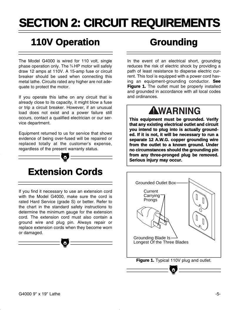
FFiigguurree 11.. Typical 110V plug and outlet.
Grounded Outlet Box
CurrentCarryingProngs
Grounding Blade IsLongest Of the Three Blades
GGrroouunnddiinngg
In the event of an electrical short, groundingreduces the risk of electric shock by providing apath of least resistance to disperse electric cur-rent. This tool is equipped with a power cord hav-ing an equipment-grounding conductor. SSeeeeFFiigguurree 11.. The outlet must be properly installedand grounded in accordance with all local codesand ordinances.
The Model G4000 is wired for 110 volt, singlephase operation only. The 3⁄4 HP motor will safelydraw 12 amps at 110V. A 15-amp fuse or circuitbreaker should be used when connecting thismetal lathe. Circuits rated any higher are not ade-quate to protect the motor.
If you operate this lathe on any circuit that isalready close to its capacity, it might blow a fuseor trip a circuit breaker. However, if an unusualload does not exist and a power failure stilloccurs, contact a qualified electrician or our ser-vice department.
Equipment returned to us for service that showsevidence of being over-fused will be repaired orreplaced totally at the customer’s expense,regardless of the present warranty status.
If you find it necessary to use an extension cordwith the Model G4000, make sure the cord israted Hard Service (grade S) or better. Refer tothe chart in the standard safety instructions todetermine the minimum gauge for the extensioncord. The extension cord must also contain aground wire and plug pin. Always repair orreplace extension cords when they become wornor damaged.
EExxtteennssiioonn CCoorrddss
TThhiiss eeqquuiippmmeenntt mmuusstt bbee ggrroouunnddeedd.. VVeerriiffyytthhaatt aannyy eexxiissttiinngg eelleeccttrriiccaall oouuttlleett aanndd cciirrccuuiittyyoouu iinntteenndd ttoo pplluugg iinnttoo iiss aaccttuuaallllyy ggrroouunndd--eedd.. IIff iitt iiss nnoott,, iitt wwiillll bbee nneecceessssaarryy ttoo rruunn aasseeppaarraattee 1122 AA..WW..GG.. ccooppppeerr ggrroouunnddiinngg wwiirreeffrroomm tthhee oouuttlleett ttoo aa kknnoowwnn ggrroouunndd.. UUnnddeerrnnoo cciirrccuummssttaanncceess sshhoouulldd tthhee ggrroouunnddiinngg ppiinnffrroomm aannyy tthhrreeee--pprroonnggeedd pplluugg bbee rreemmoovveedd..SSeerriioouuss iinnjjuurryy mmaayy ooccccuurr..
-6- G4000 9'' x 19'' Lathe
CCoommmmeennttaarryy
We are proud to offer the Grizzly Model G40009" x 19" Metal Lathe. The Model G4000 is part ofa growing Grizzly family of fine metalworkingmachinery. When used according to the guide-lines set forth in this manual, you can expectyears of trouble-free, enjoyable operation andproof of Grizzly’s commitment to customer satis-faction.
The Model G4000 is a precision metalworkinglathe. It features cast iron construction, 19" V-bed, a speed range of 130-2,000 RPM, 6-speedgearbox and a complete electrical package. Theelectrical package consists of a, 3⁄4 H.P., 110Vmotor, mechanical forward and reverse switchand cord set. We also offer many accessories forthis lathe. Please refer to the latest Grizzly cata-log for prices and information.
We are also pleased to provide this instructionalmanual with the Model G4000 Lathe. This manu-al was written to guide you through assembly,review safety considerations and cover basicoperating procedures. It represents our latesteffort to produce the best documentation possi-ble. If you have any constructive criticisms orcomments you feel we should include in our nextprinting, please write us at the address below.
Grizzly Industrial, Inc.C/O Technical Documentation
P.O. Box 2069Bellingham, WA 98227-2069
Most importantly, we stand behind our machines.If you have any service questions or partsrequests, please call or write us at the locationlisted below.
Grizzly Industrial, Inc.2406 Reach Road
Williamsport, PA 17701Phone: (570) 326-3806
Fax: (800) 438-5901E-Mail: [email protected]
Web Site: http://www.grizzly.com
The specifications, drawings, and photographsillustrated in this manual represent the ModelG4000 as supplied when the manual was pre-pared. However, owing to Grizzly’s policy of con-tinuous improvement, changes may be made atany time with no obligation on the part of Grizzly.Whenever possible, though, we send manualupdates to all owners of a particular tool ormachine. Should you receive one, we urge you toinsert the new information with the old and keepit for reference.
TToo ooppeerraattee tthhiiss,, oorr aannyy ppoowweerr ttooooll,, ssaaffeellyyaanndd eeffffiicciieennttllyy,, iitt iiss eesssseennttiiaall ttoo bbeeccoommee aassffaammiilliiaarr wwiitthh iittss cchhaarraacctteerriissttiiccss aass ppoossssiibbllee..TThhee ttiimmee yyoouu iinnvveesstt bbeeffoorree yyoouu bbeeggiinn ttoo uusseeyyoouurr MMooddeell GG44000000 wwiillll bbee ttiimmee wweellll ssppeenntt..DDOO NNOOTT ooppeerraattee tthhiiss mmaacchhiinnee uunnttiill yyoouu aarreeccoommpplleetteellyy ffaammiilliiaarr wwiitthh tthhee ccoonntteennttss ooff tthhiissmmaannuuaall.. MMaakkee ssuurree yyoouu rreeaadd aanndd uunnddeerr--ssttaanndd aallll ooff tthhee ssaaffeettyy pprroocceedduurreess.. IIff yyoouu ddoonnoott uunnddeerrssttaanndd ssoommeetthhiinngg,, DDOO NNOOTT ooppeerraatteetthhee mmaacchhiinnee..
SSEECCTTIIOONN 33:: IINNTTRROODDUUCCTTIIOONN
G4000 9'' x 19'' Lathe -7-
UUnnppaacckkiinngg
This Metal Lathe is shipped from the manufactur-er in a carefully packed carton. If you discover themachine is damaged after you’ve signed for deliv-ery, and the truck and driver are gone, you willneed to file a freight claim with the carrier. Savethe containers and all packing materials for pos-sible inspection by the carrier or its agent.Without the packing materials, filing a freightclaim can be difficult. If you need assistancedetermining whether you need to file a freightclaim, or with the procedure to file one, pleasecontact our Customer Service.
When you are completely satisfied with the con-dition of your shipment, you should inventory itsparts.
The G4000 is a heavy machine (300 lbs. ship-ping weight). DO NOT over-exert yourselfwhile unpacking or moving your machine – getassistance. In the event that your Metal Lathemust be moved up or down a flight of stairs, besure that the stairs are capable of supportingthe combined weight of people and themachine. SSeerriioouuss ppeerrssoonnaall iinnjjuurryy mmaayyooccccuurr..
PPiieeccee IInnvveennttoorryy
The Model G4000 is, for the most part, pre-assembled at the factory. Inside the crate you’llfind:
• The Model G4000 Metal Lathe• 4" 3-jaw Chuck• 7" 4-jaw Chuck• Face Plate• Steady Rest• Following Rest• 4-Way Tool Post• C-Type Tool Post• Toolbox • Metric Allen® Wrenches• 8-10mm Combination wrench• Regular Screwdriver• Phillips® Screwdriver• Oil can• 30T Gear (2) • 36T Gear • 42T Gear • 45T Gear • 80T Gear (2)• Chuck wrenches (2)• Chuck Removal Bars (2)• Reverse Jaws for the 3-Jaw Chuck• Dead Centers - MT #2, MT #3• Live Center - MT #3
In the event that any non-proprietary parts aremissing (e.g. a nut or a washer), we would beglad to replace them, or, for the sake of expedi-ency, replacements can be obtained at your localhardware store.
-8- G4000 9'' x 19'' Lathe
SSiittee CCoonnssiiddeerraattiioonnss
11.. FFlloooorr LLooaadd:: The Model G4000 can bemounted on your existing workbench or onan optional cabinet stand which is listed inour current Grizzly catalog. If you choose touse the stand, you will find the holes for bolt-ing the G4000 to the stand are already inplace. If you are using your own bench,ensure that it is strong enough to handle theG4000 lathe. Keep in mind, whichever wayyou choose to mount the lathe, it’s essentialthat the mounting surface be perfectly flat.Use an accurate carpenter’s level to ensurethat your bench is properly leveled.
22.. WWoorrkkiinngg CClleeaarraanncceess:: Consider existing andanticipated needs, size of material to beprocessed through each machine, andspace for auxiliary stands, work tables orother machinery when establishing a loca-tion for your lathe.
33.. LLiigghhttiinngg aanndd OOuuttlleettss:: Lighting should bebright enough to eliminate shadow and pre-vent eye strain. Electrical circuits should bededicated or large enough to handle amper-age requirements. Outlets should be locatednear each machine so power or extensioncords are clear of high-traffic areas. Observelocal electrical codes for proper installationof new lighting, outlets, or circuits.
CClleeaann UUpp
The unpainted surfaces are coated with a waxyoil to protect them from corrosion during ship-ment. Remove this protective coating with a sol-vent cleaner or citrus-based degreaser. Avoidchlorine-based solvents as they may damagepainted surfaces should they come in contact.Always follow the usage instructions on the prod-uct you choose for clean up.
MMaannyy ooff tthhee ssoollvveennttss ccoommmmoonnllyy uusseedd ttoocclleeaann mmaacchhiinneerryy ccaann bbee hhiigghhllyy ffllaammmmaabbllee,,aanndd ttooxxiicc wwhheenn iinnhhaalleedd oorr iinnggeesstteedd.. AAllwwaayysswwoorrkk iinn wweellll--vveennttiillaatteedd aarreeaass ffaarr ffrroommppootteennttiiaall iiggnniittiioonn ssoouurrcceess wwhheenn ddeeaalliinnggwwiitthh ssoollvveennttss.. UUssee ccaarree wwhheenn ddiissppoossiinngg ooffwwaassttee rraaggss aanndd ttoowweellss ttoo bbee ssuurree tthheeyy ddoonnoott ccrreeaattee ffiirree oorr eennvviirroonnmmeennttaall hhaazzaarrddss..KKeeeepp cchhiillddrreenn aanndd aanniimmaallss ssaaffeellyy aawwaayywwhheenn cclleeaanniinngg aanndd aasssseemmbblliinngg tthhiissmmaacchhiinnee..
DDoo nnoott uussee ggaassoolliinnee oorr ootthheerr ppeettrroolleeuumm--bbaasseedd ssoollvveennttss ttoo rreemmoovvee tthhiiss pprrootteeccttiivveeccooaattiinngg.. TThheessee pprroodduuccttss ggeenneerraallllyy hhaavvee lloowwffllaasshh ppooiinnttss wwhhiicchh mmaakkeess tthheemm eexxttrreemmeellyyffllaammmmaabbllee.. AA rriisskk ooff eexxpplloossiioonn aanndd bbuurrnniinnggeexxiissttss iiff tthheessee pprroodduuccttss aarree uusseedd.. SSeerriioouussppeerrssoonnaall iinnjjuurryy mmaayy ooccccuurr..
AAllll ddiiee--ccuutt mmeettaall ppaarrttss hhaavvee aa sshhaarrpp eeddggee((ccaalllleedd ““ffllaasshhiinngg””)) oonn tthheemm aafftteerr tthheeyy aarreeffoorrmmeedd.. TThhiiss iiss ggeenneerraallllyy rreemmoovveedd aatt tthheeffaaccttoorryy.. SSoommeettiimmeess aa bbiitt ooff ffllaasshhiinngg mmiigghhtteessccaappee iinnssppeeccttiioonn,, aanndd tthhee sshhaarrpp eeddggee mmaayyccaauussee ccuuttss oorr llaacceerraattiioonnss wwhheenn hhaannddlleedd..PPlleeaassee eexxaammiinnee tthhee eeddggeess ooff aallll ddiiee--ccuuttmmeettaall ppaarrttss aanndd ffiillee oorr ssaanndd tthhee eeddggee ttoorreemmoovvee tthhee ffllaasshhiinngg bbeeffoorree hhaannddlliinngg..
MMaakkee yyoouurr sshhoopp ““cchhiilldd ssaaffee””.. EEnnssuurree tthhaattyyoouurr wwoorrkkppllaaccee iiss iinnaacccceessssiibbllee ttoo yyoouunngg--sstteerrss bbyy cclloossiinngg aanndd lloocckkiinngg aallll eennttrraanncceesswwhheenn yyoouu aarree aawwaayy.. NNeevveerr aallllooww vviissiittoorrss iinnyyoouurr sshhoopp wwhheenn aasssseemmbblliinngg,, aaddjjuussttiinngg oorrooppeerraattiinngg eeqquuiippmmeenntt..
G4000 9'' x 19'' Lathe -9-
CChhuucckkss
The Model G4000 Metal Lathe comes equippedwith a 4'' 3-jaw chuck (already installed), a 7'' 4-jaw chuck and a face plate.
The 3-jaw chuck is a scroll-type chuck, meaningthat all three jaws move in unison when adjust-ments are made. The 4-jaw chuck, on the otherhand, features independent jaws. The 4-jawchuck is used for square or unevenly-shapedstock.
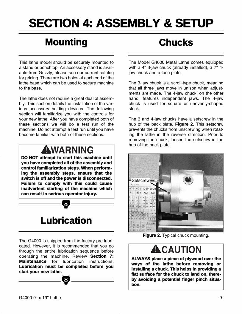
The 3 and 4-jaw chucks have a setscrew in thehub of the back plate. FFiigguurree 22.. This setscrewprevents the chucks from unscrewing when rotat-ing the lathe in the reverse direction. Prior toremoving the chuck, loosen the setscrew in thehub of the back plate.
FFiigguurree 22.. Typical chuck mounting.
MMoouunnttiinngg
This lathe model should be securely mounted toa stand or benchtop. An accessory stand is avail-able from Grizzly, please see our current catalogfor pricing. There are two holes at each end of thelathe base which can be used to secure machineto the base.
The lathe does not require a great deal of assem-bly. This section details the installation of the var-ious accessory holding devices. The followingsection will familiarize you with the controls foryour new lathe. After you have completed both ofthese sections we will do a test run of themachine. Do not attempt a test run until you havebecome familiar with both of these sections.
SSEECCTTIIOONN 44:: AASSSSEEMMBBLLYY && SSEETTUUPP
DDOO NNOOTT aatttteemmpptt ttoo ssttaarrtt tthhiiss mmaacchhiinnee uunnttiillyyoouu hhaavvee ccoommpplleetteedd aallll ooff tthhee aasssseemmbbllyy aannddccoonnttrrooll ffaammiilliiaarriizzaattiioonn sstteeppss.. WWhheenn ppeerrffoorrmm--iinngg tthhee aasssseemmbbllyy sstteeppss,, eennssuurree tthhaatt tthheesswwiittcchh iiss ooffff aanndd tthhee ppoowweerr iiss ddiissccoonnnneecctteedd..FFaaiilluurree ttoo ccoommppllyy wwiitthh tthhiiss ccoouulldd ccaauusseeiinnaaddvveerrtteenntt ssttaarrttiinngg ooff tthhee mmaacchhiinnee wwhhiicchhccaann rreessuulltt iinn sseerriioouuss ooppeerraattoorr iinnjjuurryy..
LLuubbrriiccaattiioonn
The G4000 is shipped from the factory pre-lubri-cated. However, it is recommended that you gothrough the entire lubrication sequence beforeoperating the machine. Review SSeeccttiioonn 77::MMaaiinntteennaannccee for lubrication instructions.LLuubbrriiccaattiioonn mmuusstt bbee ccoommpplleetteedd bbeeffoorree yyoouussttaarrtt yyoouurr nneeww llaatthhee..
Setscrew
AALLWWAAYYSS ppllaaccee aa ppiieeccee ooff ppllyywwoooodd oovveerr tthheewwaayyss ooff tthhee llaatthhee bbeeffoorree rreemmoovviinngg oorriinnssttaalllliinngg aa cchhuucckk.. TThhiiss hheellppss iinn pprroovviiddiinngg aaffllaatt ssuurrffaaccee ffoorr tthhee cchhuucckk ttoo llaanndd oonn,, tthheerree--bbyy aavvooiiddiinngg aa ppootteennttiiaall ffiinnggeerr ppiinncchh ssiittuuaa--ttiioonn..
-10- G4000 9'' x 19'' Lathe
FFiigguurree 33.. Chuck removal bars in place.
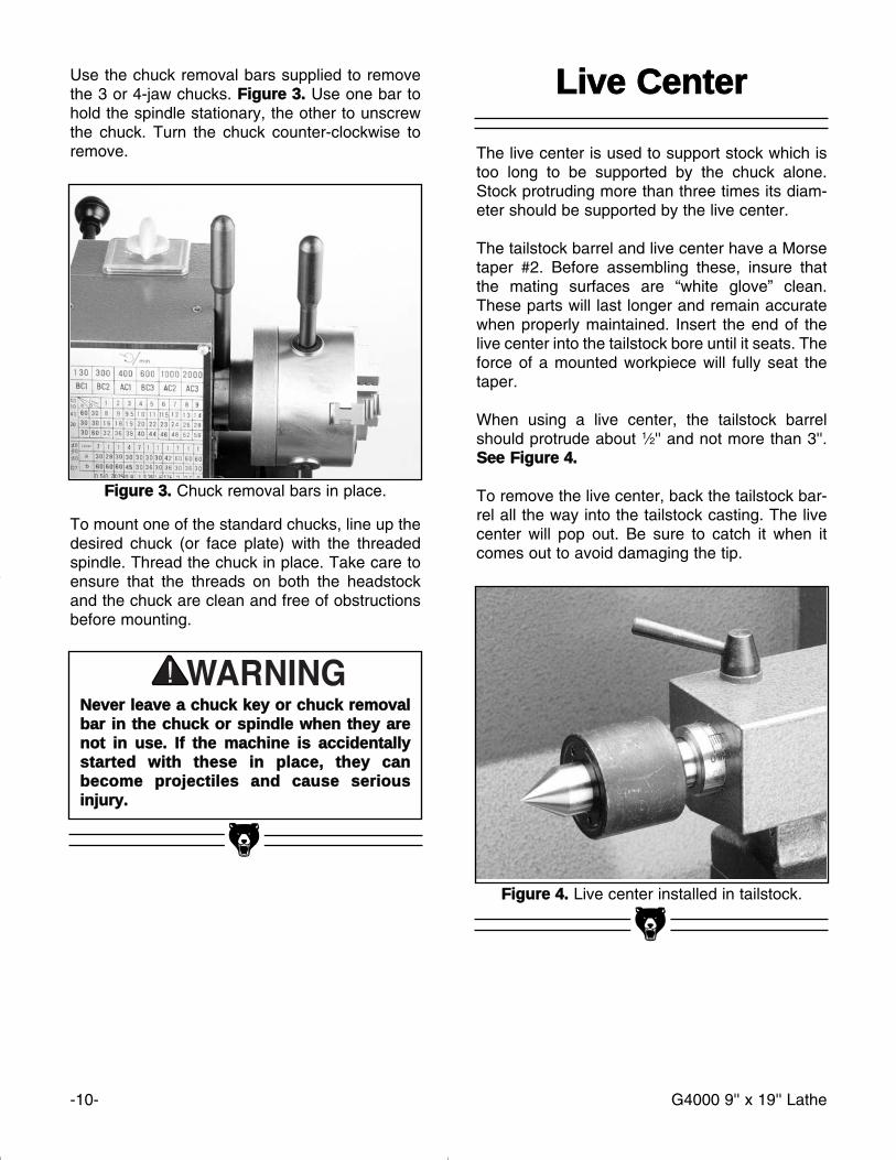
Use the chuck removal bars supplied to removethe 3 or 4-jaw chucks. FFiigguurree 33.. Use one bar tohold the spindle stationary, the other to unscrewthe chuck. Turn the chuck counter-clockwise toremove.
To mount one of the standard chucks, line up thedesired chuck (or face plate) with the threadedspindle. Thread the chuck in place. Take care toensure that the threads on both the headstockand the chuck are clean and free of obstructionsbefore mounting.
LLiivvee CCeenntteerr
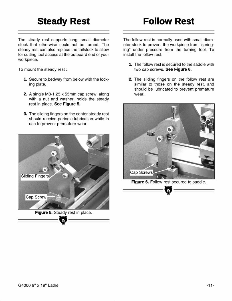
The live center is used to support stock which istoo long to be supported by the chuck alone.Stock protruding more than three times its diam-eter should be supported by the live center.
The tailstock barrel and live center have a Morsetaper #2. Before assembling these, insure thatthe mating surfaces are “white glove” clean.These parts will last longer and remain accuratewhen properly maintained. Insert the end of thelive center into the tailstock bore until it seats. Theforce of a mounted workpiece will fully seat thetaper.
When using a live center, the tailstock barrelshould protrude about 1⁄2'' and not more than 3''.SSeeee FFiigguurree 44..
To remove the live center, back the tailstock bar-rel all the way into the tailstock casting. The livecenter will pop out. Be sure to catch it when itcomes out to avoid damaging the tip.
FFiigguurree 44.. Live center installed in tailstock.
NNeevveerr lleeaavvee aa cchhuucckk kkeeyy oorr cchhuucckk rreemmoovvaallbbaarr iinn tthhee cchhuucckk oorr ssppiinnddllee wwhheenn tthheeyy aarreennoott iinn uussee.. IIff tthhee mmaacchhiinnee iiss aacccciiddeennttaallllyyssttaarrtteedd wwiitthh tthheessee iinn ppllaaccee,, tthheeyy ccaannbbeeccoommee pprroojjeeccttiilleess aanndd ccaauussee sseerriioouussiinnjjuurryy..
G4000 9'' x 19'' Lathe -11-
The follow rest is normally used with small diam-eter stock to prevent the workpiece from ''spring-ing'' under pressure from the turning tool. Toinstall the follow rest:
11.. The follow rest is secured to the saddle withtwo cap screws. SSeeee FFiigguurree 66..
22.. The sliding fingers on the follow rest aresimilar to those on the steady rest, andshould be lubricated to prevent prematurewear.
FFiigguurree 66.. Follow rest secured to saddle.
FFiigguurree 55.. Steady rest in place.
SStteeaaddyy RReesstt
The steady rest supports long, small diameterstock that otherwise could not be turned. Thesteady rest can also replace the tailstock to allowfor cutting tool access at the outboard end of yourworkpiece.
To mount the steady rest :
11.. Secure to bedway from below with the lock-ing plate.
22.. A single M8-1.25 x 55mm cap screw, alongwith a nut and washer, holds the steadyrest in place. SSeeee FFiigguurree 55..
33.. The sliding fingers on the center steady restshould receive periodic lubrication while inuse to prevent premature wear.
FFoollllooww RReesstt
Sliding Fingers
Cap Screw
Cap Screws
-12- G4000 9'' x 19'' Lathe
SSppiinnddllee SSppeeeeddss
SSEECCTTIIOONN 55:: CCOONNTTRROOLLSS
FFiigguurree 99.. Belt tensioning lever.
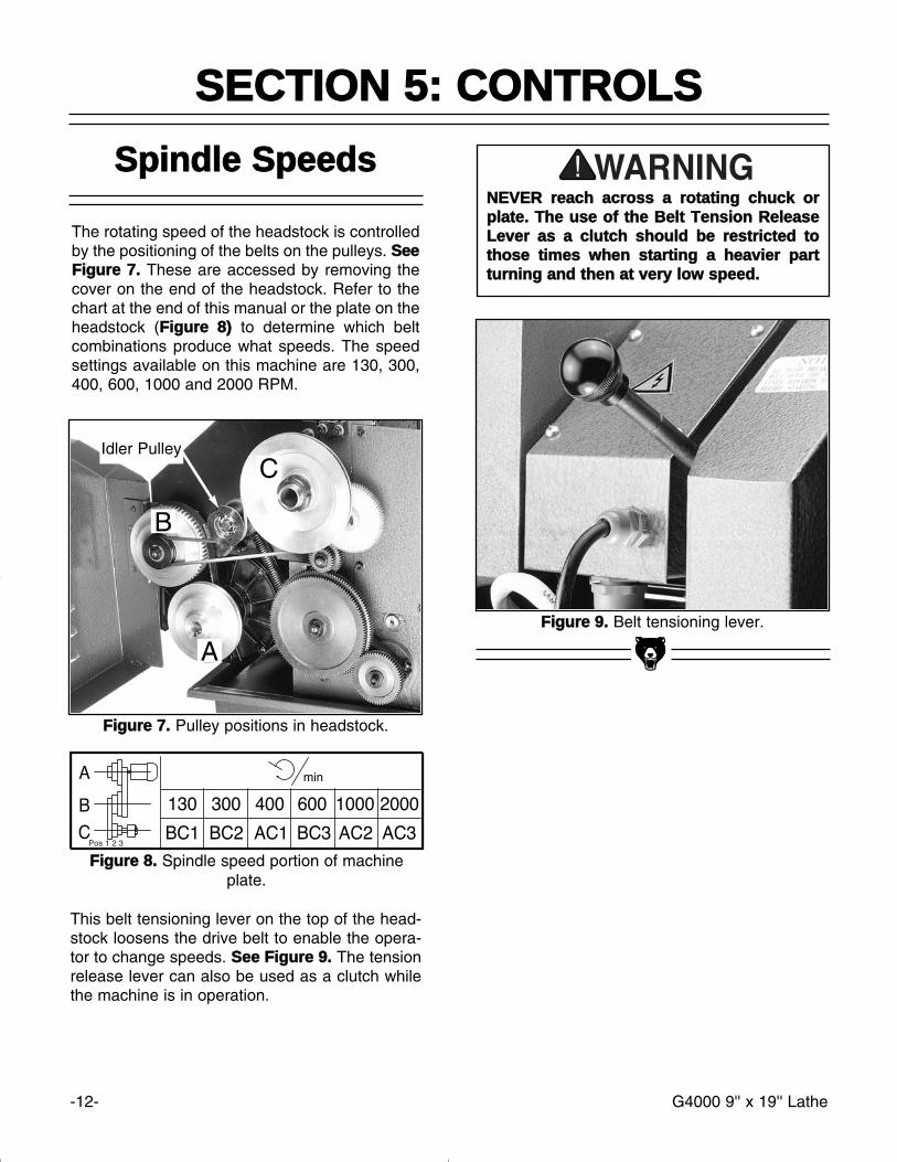
FFiigguurree 88.. Spindle speed portion of machineplate.
FFiigguurree 77.. Pulley positions in headstock.
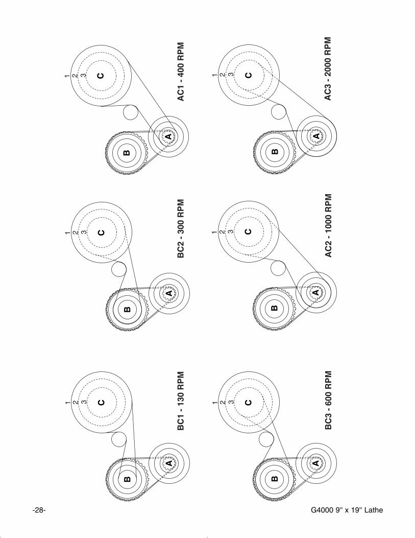
The rotating speed of the headstock is controlledby the positioning of the belts on the pulleys. SSeeeeFFiigguurree 77.. These are accessed by removing thecover on the end of the headstock. Refer to thechart at the end of this manual or the plate on theheadstock (FFiigguurree 88)) to determine which beltcombinations produce what speeds. The speedsettings available on this machine are 130, 300,400, 600, 1000 and 2000 RPM.
NNEEVVEERR rreeaacchh aaccrroossss aa rroottaattiinngg cchhuucckk oorrppllaattee.. TThhee uussee ooff tthhee BBeelltt TTeennssiioonn RReelleeaasseeLLeevveerr aass aa cclluuttcchh sshhoouulldd bbee rreessttrriicctteedd ttootthhoossee ttiimmeess wwhheenn ssttaarrttiinngg aa hheeaavviieerr ppaarrttttuurrnniinngg aanndd tthheenn aatt vveerryy llooww ssppeeeedd..
This belt tensioning lever on the top of the head-stock loosens the drive belt to enable the opera-tor to change speeds. SSeeee FFiigguurree 99.. The tensionrelease lever can also be used as a clutch whilethe machine is in operation.
A
B
CIdler Pulley
G4000 9'' x 19'' Lathe -13-
FFiigguurree 1122.. Threading rates portion of machineplate.
FFeeeedd RRaattee
The lever at the bottom of the headstockchanges the feed rate, or the number of threads-per-inch. SSeeee FFiigguurree 99.. The lever can beengaged in any of nine different positions. Whenused in conjunction with the interchangeablegears supplied it is possible to achieve a widevariety of feed or threading rates.
FFiigguurree 1100.. Feed rate selector lever.
FFiigguurree 1111.. Feed rates portion of machine plate.
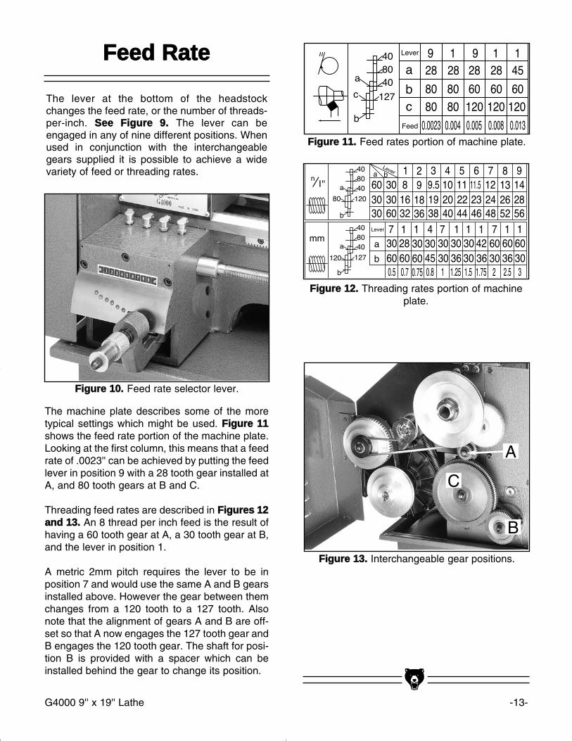
The machine plate describes some of the moretypical settings which might be used. FFiigguurree 1111shows the feed rate portion of the machine plate.Looking at the first column, this means that a feedrate of .0023'' can be achieved by putting the feedlever in position 9 with a 28 tooth gear installed atA, and 80 tooth gears at B and C.
Threading feed rates are described in FFiigguurreess 1122aanndd 1133.. An 8 thread per inch feed is the result ofhaving a 60 tooth gear at A, a 30 tooth gear at B,and the lever in position 1.
A metric 2mm pitch requires the lever to be inposition 7 and would use the same A and B gearsinstalled above. However the gear between themchanges from a 120 tooth to a 127 tooth. Alsonote that the alignment of gears A and B are off-set so that A now engages the 127 tooth gear andB engages the 120 tooth gear. The shaft for posi-tion B is provided with a spacer which can beinstalled behind the gear to change its position.
FFiigguurree 1133.. Interchangeable gear positions.
A
B
C
-14-
FFiigguurree 1166.. Top slide handwheel.
TToopp SSlliiddee HHaannddwwhheeeell -- The Top SlideHandwheel controls the position of the cuttingtool relative to the workpiece. The top slide isadjustable for angle as well as longitudinal trav-el. It can be adjusted a full 360°, if needed. Thegraduated scale is adjustable using the samemethod as the other handwheels. Angle adjust-ment is controlled by cap screws in the base ofthe top slide. FFiigguurree 1166..
FFiigguurree 1155.. Cross slide handwheel.
CCrroossss SSlliiddee HHaannddwwhheeeell -- The Cross SlideHandwheel moves the top slide toward and awayfrom the work. Turning the dial clockwise movesthe slide toward the workpiece. The graduatedscale can be adjusted using the same method asthe longitudinal scale. FFiigguurree 1155..
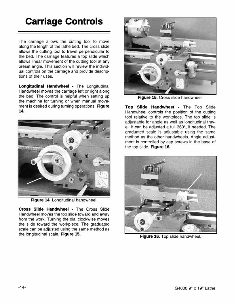
FFiigguurree 1144.. Longitudinal handwheel.
CCaarrrriiaaggee CCoonnttrroollss
The carriage allows the cutting tool to movealong the length of the lathe bed. The cross slideallows the cutting tool to travel perpendicular tothe bed. The carriage features a top slide whichallows linear movement of the cutting tool at anypreset angle. This section will review the individ-ual controls on the carriage and provide descrip-tions of their uses.
LLoonnggiittuuddiinnaall HHaannddwwhheeeell -- The LongitudinalHandwheel moves the carriage left or right alongthe bed. The control is helpful when setting upthe machine for turning or when manual move-ment is desired during turning operations. FFiigguurree1144..
G4000 9'' x 19'' Lathe
G4000 9'' x 19'' Lathe -15-
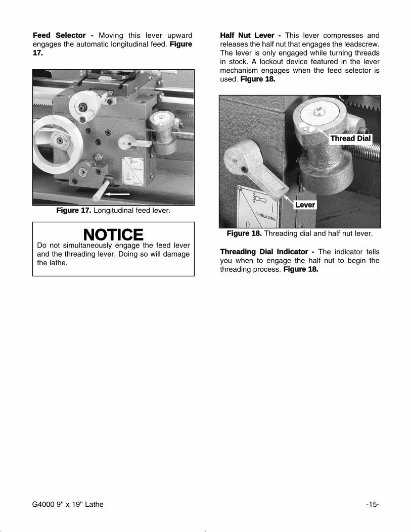
FFiigguurree 1188.. Threading dial and half nut lever.
HHaallff NNuutt LLeevveerr -- This lever compresses andreleases the half nut that engages the leadscrew.The lever is only engaged while turning threadsin stock. A lockout device featured in the levermechanism engages when the feed selector isused. FFiigguurree 1188..
TThhrreeaaddiinngg DDiiaall IInnddiiccaattoorr -- The indicator tellsyou when to engage the half nut to begin thethreading process. FFiigguurree 1188..
LLeevveerr
TThhrreeaadd DDiiaall
NNOOTTIICCEEDo not simultaneously engage the feed leverand the threading lever. Doing so will damagethe lathe.
FFiigguurree 1177.. Longitudinal feed lever.
FFeeeedd SSeelleeccttoorr -- Moving this lever upwardengages the automatic longitudinal feed. FFiigguurree1177..
-16- G4000 9'' x 19'' Lathe
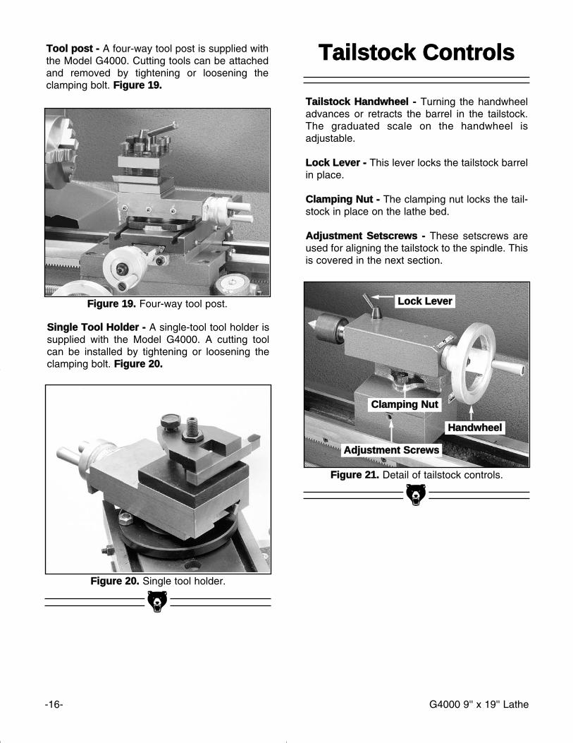
FFiigguurree 2211.. Detail of tailstock controls.
TTaaiillssttoocckk CCoonnttrroollss
TTaaiillssttoocckk HHaannddwwhheeeell -- Turning the handwheeladvances or retracts the barrel in the tailstock.The graduated scale on the handwheel isadjustable.
LLoocckk LLeevveerr -- This lever locks the tailstock barrelin place.
CCllaammppiinngg NNuutt -- The clamping nut locks the tail-stock in place on the lathe bed.
AAddjjuussttmmeenntt SSeettssccrreewwss -- These setscrews areused for aligning the tailstock to the spindle. Thisis covered in the next section.
FFiigguurree 2200.. Single tool holder.
SSiinnggllee TTooooll HHoollddeerr -- A single-tool tool holder issupplied with the Model G4000. A cutting toolcan be installed by tightening or loosening theclamping bolt. FFiigguurree 2200..
AAddjjuussttmmeenntt SSccrreewwss
CCllaammppiinngg NNuutt
HHaannddwwhheeeell
LLoocckk LLeevveerrFFiigguurree 1199.. Four-way tool post.
TTooooll ppoosstt -- A four-way tool post is supplied withthe Model G4000. Cutting tools can be attachedand removed by tightening or loosening theclamping bolt. FFiigguurree 1199..
G4000 9'' x 19'' Lathe -17-
TTeesstt RRuunn NNootteess
Now that the lathe is securely in place and you’veread the safety guidelines, it’s time to give themachine a test run.
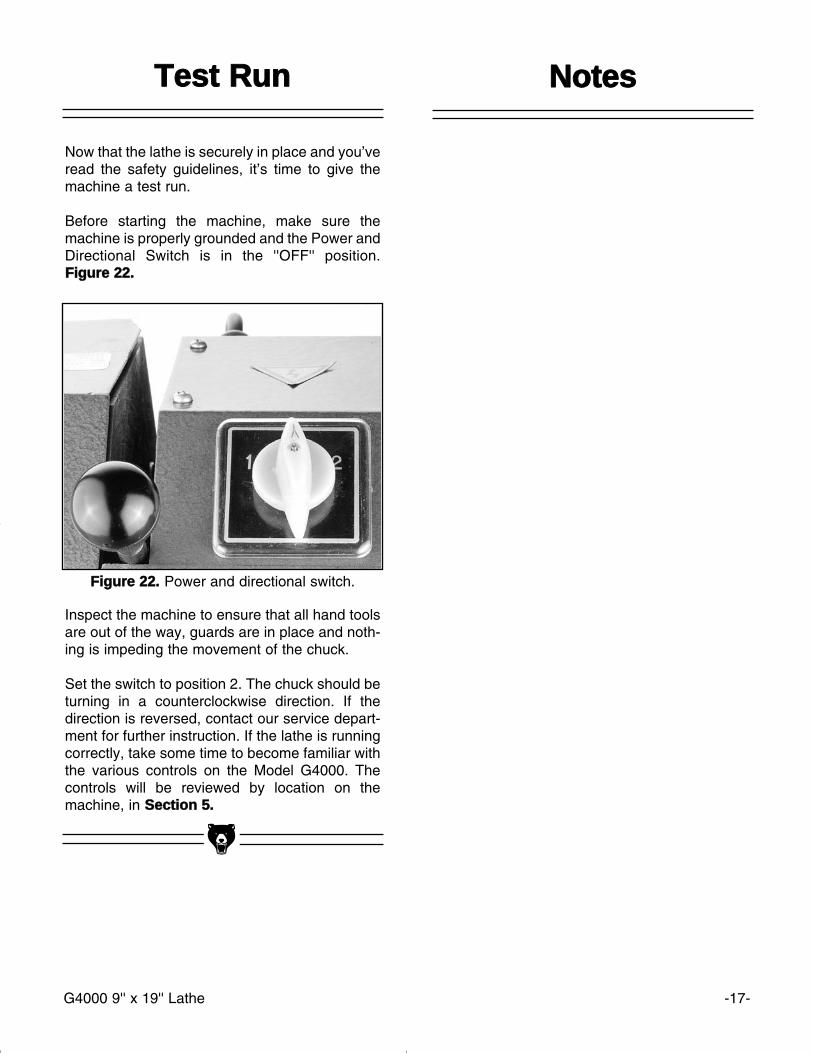
Before starting the machine, make sure themachine is properly grounded and the Power andDirectional Switch is in the ''OFF'' position.FFiigguurree 2222..
Inspect the machine to ensure that all hand toolsare out of the way, guards are in place and noth-ing is impeding the movement of the chuck.
Set the switch to position 2. The chuck should beturning in a counterclockwise direction. If thedirection is reversed, contact our service depart-ment for further instruction. If the lathe is runningcorrectly, take some time to become familiar withthe various controls on the Model G4000. Thecontrols will be reviewed by location on themachine, in SSeeccttiioonn 55..
FFiigguurree 2222.. Power and directional switch.
-18- G4000 9'' x 19'' Lathe
NNOOTTIICCEEWhen adjusting gibs, keep in mind that thegoal of gib adjustment is to remove unneces-sary sloppiness from the slide’s movementwithout causing them to bind. Overtighteningmay cause premature wear.
SSppiinnddllee RRPPMM
SSEECCTTIIOONN 66:: AADDJJUUSSTTMMEENNTTSS
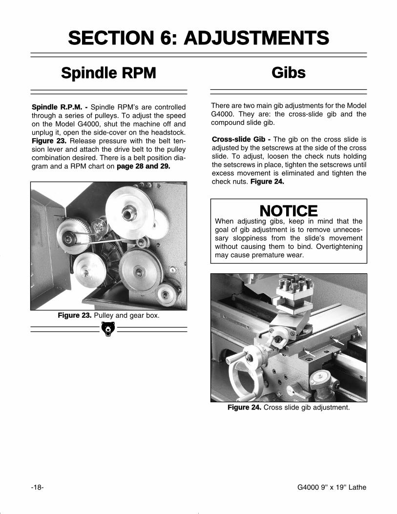
FFiigguurree 2233.. Pulley and gear box.
SSppiinnddllee RR..PP..MM.. -- Spindle RPM’s are controlledthrough a series of pulleys. To adjust the speedon the Model G4000, shut the machine off andunplug it, open the side-cover on the headstock.FFiigguurree 2233.. Release pressure with the belt ten-sion lever and attach the drive belt to the pulleycombination desired. There is a belt position dia-gram and a RPM chart on ppaaggee 2288 aanndd 2299..
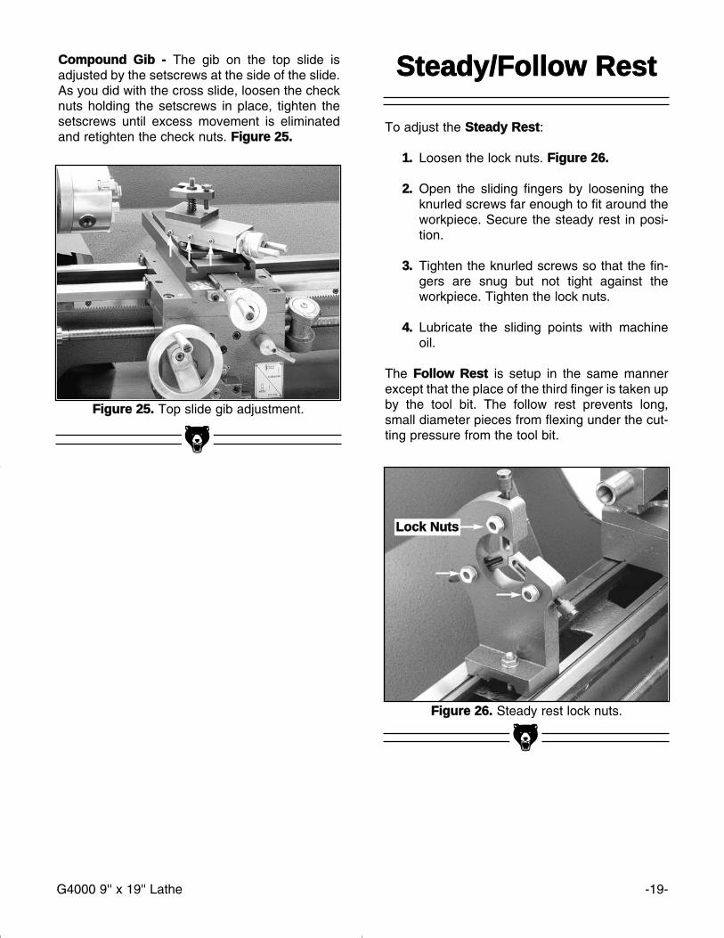
FFiigguurree 2244.. Cross slide gib adjustment.
There are two main gib adjustments for the ModelG4000. They are: the cross-slide gib and thecompound slide gib.
CCrroossss--sslliiddee GGiibb -- The gib on the cross slide isadjusted by the setscrews at the side of the crossslide. To adjust, loosen the check nuts holdingthe setscrews in place, tighten the setscrews untilexcess movement is eliminated and tighten thecheck nuts. FFiigguurree 2244..
GGiibbss
G4000 9'' x 19'' Lathe -19-
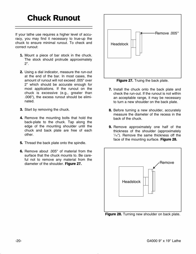
CCoommppoouunndd GGiibb -- The gib on the top slide isadjusted by the setscrews at the side of the slide.As you did with the cross slide, loosen the checknuts holding the setscrews in place, tighten thesetscrews until excess movement is eliminatedand retighten the check nuts. FFiigguurree 2255..
FFiigguurree 2255.. Top slide gib adjustment.
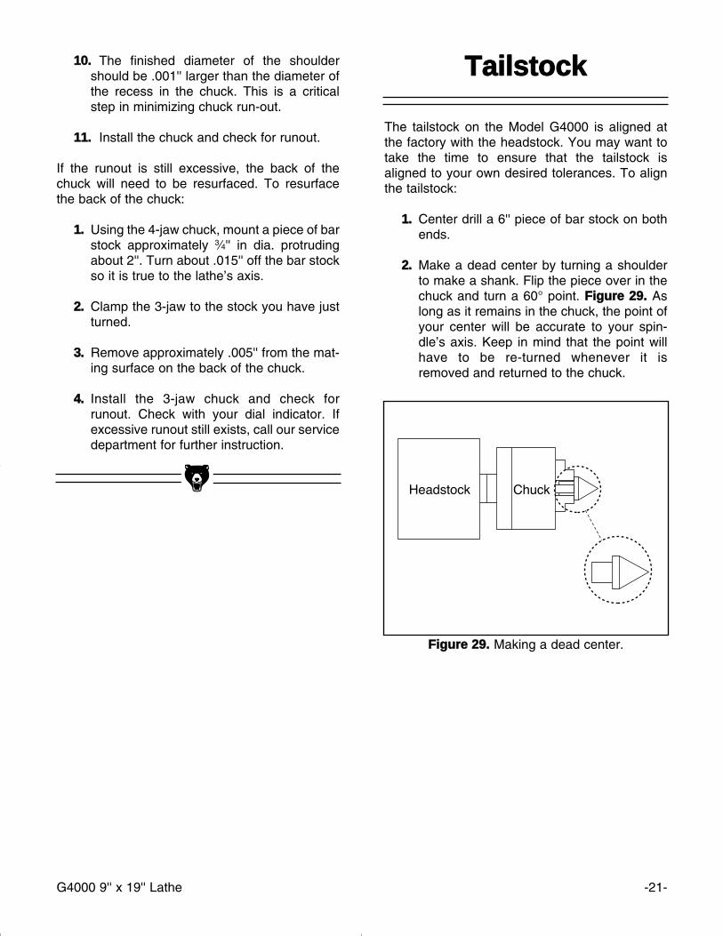
FFiigguurree 2266.. Steady rest lock nuts.
SStteeaaddyy//FFoollllooww RReesstt
To adjust the SStteeaaddyy RReesstt:
11.. Loosen the lock nuts. FFiigguurree 2266..
22.. Open the sliding fingers by loosening theknurled screws far enough to fit around theworkpiece. Secure the steady rest in posi-tion.
33.. Tighten the knurled screws so that the fin-gers are snug but not tight against theworkpiece. Tighten the lock nuts.
44.. Lubricate the sliding points with machineoil.
The FFoollllooww RReesstt is setup in the same mannerexcept that the place of the third finger is taken upby the tool bit. The follow rest prevents long,small diameter pieces from flexing under the cut-ting pressure from the tool bit.
LLoocckk NNuuttss
-20- G4000 9'' x 19'' Lathe
FFiigguurree 2277.. Truing the back plate.
CChhuucckk RRuunnoouutt
If your lathe use requires a higher level of accu-racy, you may find it necessary to true-up thechuck to ensure minimal runout. To check andcorrect runout:
11.. Mount a piece of bar stock in the chuck.The stock should protrude approximately2''.
22.. Using a dial indicator, measure the run-outat the end of the bar. In most cases, theamount of runout will not exceed .005" over2" which should be accurate enough formost applications. If the runout on thechuck is excessive (e.g., greater than.006"), the excess runout should be elimi-nated.
33.. Start by removing the chuck.
44.. Remove the mounting bolts that hold theback-plate to the chuck. Tap along theedge of the mounting shoulder until thechuck and back plate are free of eachother.
55.. Thread the back plate onto the spindle.
66.. Remove about .005'' of material from thesurface that the chuck mounts to. Be care-ful not to remove any material from thediameter of the shoulder. FFiigguurree 2277..
77.. Install the chuck onto the back plate andcheck the run-out. If the runout is not withinan acceptable range, it may be necessaryto turn a new shoulder on the back plate.
88.. Before turning a new shoulder, accuratelymeasure the diameter of the recess in theback of the chuck.
99.. Remove approximately one half of thethickness of the shoulder (approximately1⁄16"). Remove the same thickness off theface of the mounting surface. FFiigguurree 2288..
FFiigguurree 2288.. Turning new shoulder on back plate.
G4000 9'' x 19'' Lathe -21-
FFiigguurree 2299.. Making a dead center.
1100.. The finished diameter of the shouldershould be .001'' larger than the diameter ofthe recess in the chuck. This is a criticalstep in minimizing chuck run-out.
1111.. Install the chuck and check for runout.
If the runout is still excessive, the back of thechuck will need to be resurfaced. To resurfacethe back of the chuck:
11.. Using the 4-jaw chuck, mount a piece of barstock approximately 3⁄4'' in dia. protrudingabout 2''. Turn about .015'' off the bar stockso it is true to the lathe’s axis.
22.. Clamp the 3-jaw to the stock you have justturned.
33.. Remove approximately .005'' from the mat-ing surface on the back of the chuck.
44.. Install the 3-jaw chuck and check forrunout. Check with your dial indicator. Ifexcessive runout still exists, call our servicedepartment for further instruction.
TTaaiillssttoocckk
The tailstock on the Model G4000 is aligned atthe factory with the headstock. You may want totake the time to ensure that the tailstock isaligned to your own desired tolerances. To alignthe tailstock:
11.. Center drill a 6'' piece of bar stock on bothends.
22.. Make a dead center by turning a shoulderto make a shank. Flip the piece over in thechuck and turn a 60° point. FFiigguurree 2299.. Aslong as it remains in the chuck, the point ofyour center will be accurate to your spin-dle’s axis. Keep in mind that the point willhave to be re-turned whenever it isremoved and returned to the chuck.
-22- G4000 9'' x 19'' Lathe
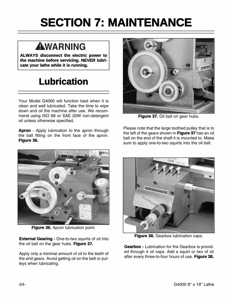
NNOOTTIICCEEDDoo NNoott forget to lock down the tailstock aftereach adjustment.
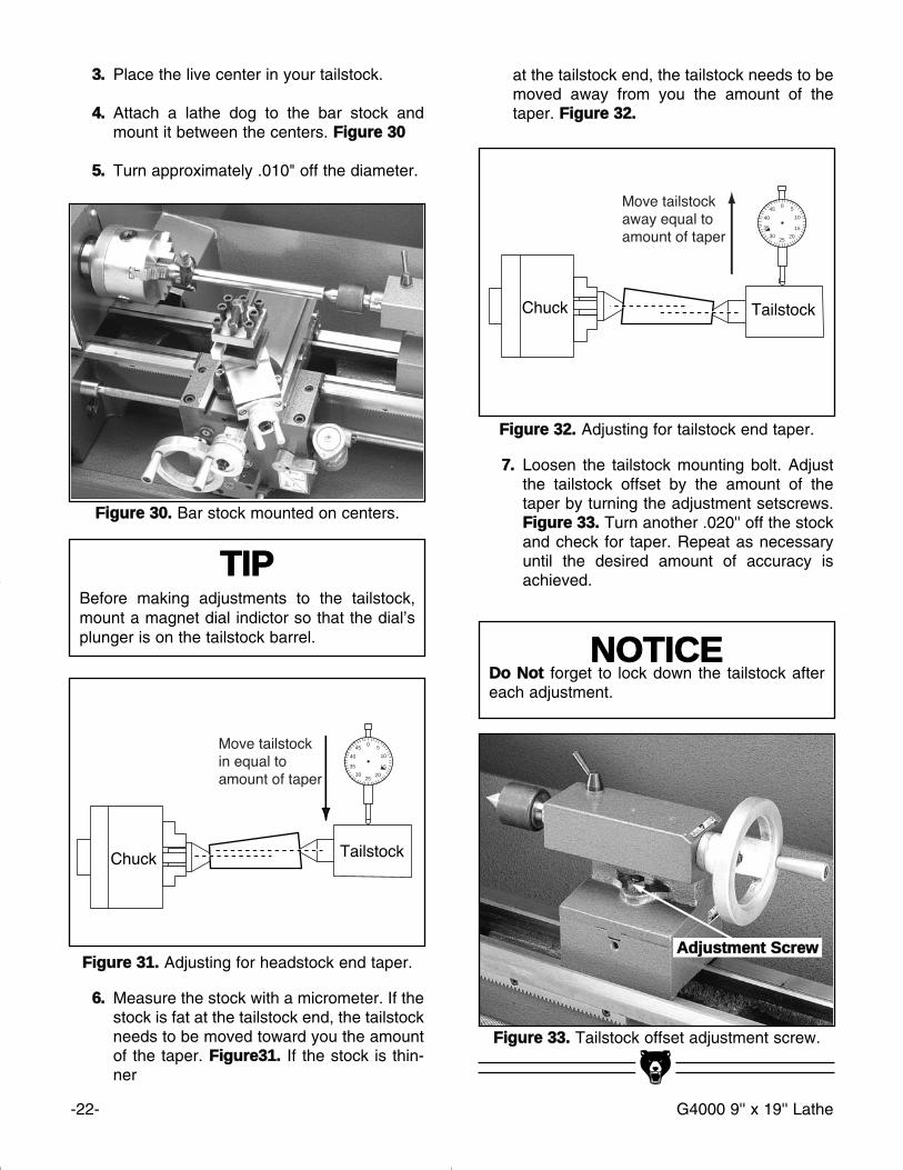
FFiigguurree 3300.. Bar stock mounted on centers.
FFiigguurree 3311.. Adjusting for headstock end taper.
05
10
15
2025
30
35
40
45
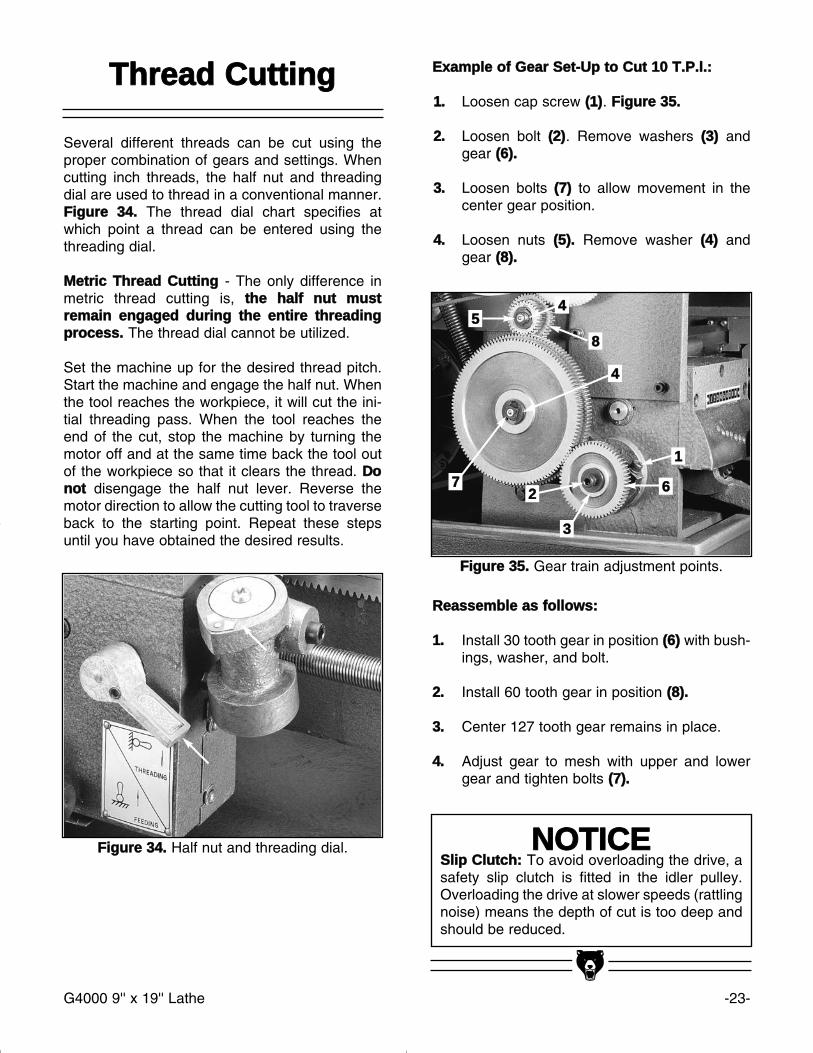
FFiigguurree 3322.. Adjusting for tailstock end taper.
05
10
15
2025
30
35
40
45
FFiigguurree 3333.. Tailstock offset adjustment screw.
33.. Place the live center in your tailstock.
44.. Attach a lathe dog to the bar stock andmount it between the centers. FFiigguurree 3300
55.. Turn approximately .010" off the diameter.
66.. Measure the stock with a micrometer. If thestock is fat at the tailstock end, the tailstockneeds to be moved toward you the amountof the taper. FFiigguurree3311.. If the stock is thin-ner
77.. Loosen the tailstock mounting bolt. Adjustthe tailstock offset by the amount of thetaper by turning the adjustment setscrews.FFiigguurree 3333.. Turn another .020'' off the stockand check for taper. Repeat as necessaryuntil the desired amount of accuracy isachieved.
AAddjjuussttmmeenntt SSccrreeww
TTIIPPBefore making adjustments to the tailstock,mount a magnet dial indictor so that the dial’splunger is on the tailstock barrel.
at the tailstock end, the tailstock needs to bemoved away from you the amount of thetaper. FFiigguurree 3322..
G4000 9'' x 19'' Lathe -23-
NNOOTTIICCEESSlliipp CClluuttcchh:: To avoid overloading the drive, asafety slip clutch is fitted in the idler pulley.Overloading the drive at slower speeds (rattlingnoise) means the depth of cut is too deep andshould be reduced.
EExxaammppllee ooff GGeeaarr SSeett--UUpp ttoo CCuutt 1100 TT..PP..ll..::
11.. Loosen cap screw ((11)). FFiigguurree 3355..
22.. Loosen bolt ((22)). Remove washers ((33)) andgear ((66))..
33.. Loosen bolts ((77)) to allow movement in thecenter gear position.
44.. Loosen nuts ((55)).. Remove washer ((44)) andgear ((88))..
RReeaasssseemmbbllee aass ffoolllloowwss::
11.. Install 30 tooth gear in position ((66)) with bush-ings, washer, and bolt.
22.. Install 60 tooth gear in position ((88))..
33.. Center 127 tooth gear remains in place.
44.. Adjust gear to mesh with upper and lowergear and tighten bolts ((77))..
TThhrreeaadd CCuuttttiinngg
Several different threads can be cut using theproper combination of gears and settings. Whencutting inch threads, the half nut and threadingdial are used to thread in a conventional manner.FFiigguurree 3344.. The thread dial chart specifies atwhich point a thread can be entered using thethreading dial.
MMeettrriicc TThhrreeaadd CCuuttttiinngg - The only difference inmetric thread cutting is, tthhee hhaallff nnuutt mmuussttrreemmaaiinn eennggaaggeedd dduurriinngg tthhee eennttiirree tthhrreeaaddiinnggpprroocceessss.. The thread dial cannot be utilized.
Set the machine up for the desired thread pitch.Start the machine and engage the half nut. Whenthe tool reaches the workpiece, it will cut the ini-tial threading pass. When the tool reaches theend of the cut, stop the machine by turning themotor off and at the same time back the tool outof the workpiece so that it clears the thread. DDoonnoott disengage the half nut lever. Reverse themotor direction to allow the cutting tool to traverseback to the starting point. Repeat these stepsuntil you have obtained the desired results.
FFiigguurree 3344.. Half nut and threading dial.
FFiigguurree 3355.. Gear train adjustment points.
5544
88
44
7722
33
66
11
-24- G4000 9'' x 19'' Lathe
SSEECCTTIIOONN 77:: MMAAIINNTTEENNAANNCCEE
LLuubbrriiccaattiioonn
GGeeaarrbbooxx -- Lubrication for the Gearbox is provid-ed through 4 oil caps. Add a squirt or two of oilafter every three-to-four hours of use. FFiigguurree 3388..
Your Model G4000 will function best when it isclean and well lubricated. Take the time to wipedown and oil the machine after use. We recom-mend using ISO 68 or SAE 20W non-detergentoil unless otherwise specified.
AApprroonn - Apply lubrication to the apron throughthe ball fitting on the front face of the apron.FFiigguurree 3366..
EExxtteerrnnaall GGeeaarriinngg -- One-to-two squirts of oil intothe oil ball on the gear hubs. FFiigguurree 3377..
Apply only a minimal amount of oil to the teeth ofthe end gears. Avoid getting oil on the belt or pul-leys when lubricating.
FFiigguurree 3366.. Apron lubrication point.
FFiigguurree 3377.. Oil ball on gear hubs.
FFiigguurree 3388.. Gearbox lubrication caps.
AALLWWAAYYSS ddiissccoonnnneecctt tthhee eelleeccttrriicc ppoowweerr ttootthhee mmaacchhiinnee bbeeffoorree sseerrvviicciinngg.. NNEEVVEERR lluubbrrii--ccaattee yyoouurr llaatthhee wwhhiillee iitt iiss rruunnnniinngg..
Please note that the large toothed pulley that is tothe left of the gears shown in FFiigguurree 3377 has an oilball on the end of the shaft it is mounted to. Makesure to apply one-to-two squirts into the oil ball.
G4000 9'' x 19'' Lathe -25-
BBeeaarriinngg PPrreellooaadd
This lathe is shipped from the factory with thebearing preload already set. If the preloadrequires resetting for whatever reason, pleasecontact our service department for furtherinstruction.
MMoottoorr -- The bearings used in the motor areshielded and lubricated for life.
WWaayyss,, SSlliiddeess -- Apply oil to the ways and slidesafter each use. Wipe the ways with a clean ragprior to lubrication to ensure that no grime is car-ried along with your lubricant into friction-sensi-tive areas. Applying oil to the bedways and otherbare metal parts also protect the lathe from rustand pitting.
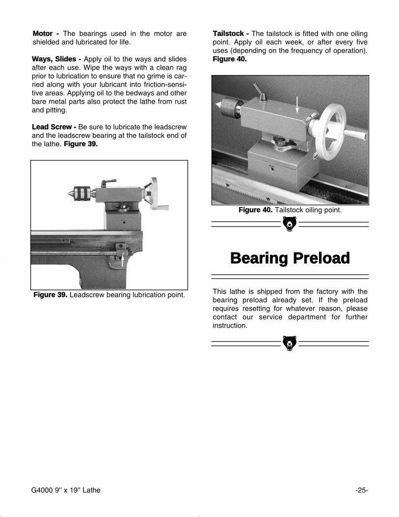
LLeeaadd SSccrreeww -- Be sure to lubricate the leadscrewand the leadscrew bearing at the tailstock end ofthe lathe. FFiigguurree 3399..
TTaaiillssttoocckk -- The tailstock is fitted with one oilingpoint. Apply oil each week, or after every fiveuses (depending on the frequency of operation).FFiigguurree 4400..
FFiigguurree 3399.. Leadscrew bearing lubrication point.
FFiigguurree 4400.. Tailstock oiling point.
-26- G4000 9'' x 19'' Lathe
NNOOTTIICCEEThe Model G4000 was specifically designedfor turning operations. DDOO NNOOTT MMOODDIIFFYYAANNDD//OORR UUSSEE TTHHIISS LLAATTHHEE FFOORR AANNYYOOTTHHEERR PPUURRPPOOSSEE.. MMooddiiffiiccaattiioonnss oorriimmpprrooppeerr uussee ooff tthhiiss ttooooll wwiillll vvooiidd tthhee wwaarr--rraannttyy.. If you are confused about any aspect ofthis machine, DDOO NNOOTT use it until you haveanswered all your questions.
The following pages contain general machinedata, parts diagram, parts lists and Warranty/Returninformation for your Model G4000.
If you need parts or help in assembling yourmachine, or if you need operational information,we encourage you to call our ServiceDepartment. Our trained service technicians willbe glad to help you. If you have comments deal-ing specifically with this manual, please write toour Bellingham, Washington location using theaddress in the Introduction section of this manu-al.
The specifications, drawings, and photographsillustrated in this manual represent the ModelG4000 as supplied when the manual was pre-pared. However, due to Grizzly’s policy of contin-uous improvement, changes may be made at anytime with no obligation on the part of Grizzly.Whenever possible, though, we send manualupdates to all owners of a particular tool ormachine. Should you receive one, add the newinformation to this manual and keep it for refer-ence.
We have included some important safety mea-sures that are essential to this machine’s opera-tion. While most safety measures are generallyuniversal, Grizzly reminds you that each workshop is different and safety rules should be con-sidered as they apply to your specific situation.
We recommend you keep a copy of our currentcatalog for complete information regardingGrizzly's warranty and return policy. If you needadditional technical information relating to thismachine, or if you need general assistance orreplacement parts, please contact the ServiceDepartment listed in the General Information.
This machine is designed for highly-skilled indi-viduals who have an understanding of metal-working. We realize there are numerous kinds ofcutters and specialized techniques used to turnmetals. To list all of the techniques necessary tooperate a metal lathe correctly for specific appli-cations would require many volumes. Additionalinformation sources are necessary to realize thefull potential of this machine. Trade journals, met-alworking magazines, and your local library aregood places to start.
SSEECCTTIIOONN 88:: CCLLOOSSUURREE
AAss wwiitthh aallll ppoowweerr ttoooollss,, tthheerree iiss ddaannggeerraassssoocciiaatteedd wwiitthh tthhee MMooddeell GG44000000.. UUssee tthheettooooll wwiitthh rreessppeecctt aanndd ccaauuttiioonn ttoo lleesssseenn tthheeppoossssiibbiilliittyy ooff mmeecchhaanniiccaall ddaammaaggee oorr ooppeerraa--ttoorr iinnjjuurryy.. IIff nnoorrmmaall ssaaffeettyy pprreeccaauuttiioonnss aarreeoovveerrllooookkeedd oorr iiggnnoorreedd,, iinnjjuurryy ttoo tthhee ooppeerraa--ttoorr oorr ootthheerrss iinn tthhee aarreeaa iiss lliikkeellyy..

G4000 9'' x 19'' Lathe -27-
Customer Service #: (570) 326-3806 • To Order Call: (800) 523-4777 • Fax #: (800) 438-5901
GGRRIIZZZZLLYY MMOODDEELL GG44000000 99"" XX 1199"" BBEENNCCHH LLAATTHHEE
MMAACCHHIINNEE DDAATTAASSHHEEEETT
Design Type ....................................................................................................Bench Model
OOvveerraallll DDiimmeennssiioonnss::Overall Length ......................................................................................................361⁄2"Overall Width ............................................................................................................22"Height ......................................................................................................................15"Bed Width ................................................................................................................41⁄2"Spindle Bore ..............................................................................................................3⁄4''Spindle Taper......................................................................................# 3 Morse TaperTailstock Taper....................................................................................# 2 Morse TaperWeight (Net) ......................................................................................................250 lbs. Weight (Shipping)..............................................................................................300 lbs.Crate Size ..................................................................................41" L x 22" W x 19" HFootprint ..........................................................................................................37" x 16"
CCoonnssttrruuccttiioonn:: ........................................................................................................Cast IronCCaappaacciittyy::
Swing Over Bed ........................................................................................................9''Swing Over Saddle ....................................................................................................5''Carriage Travel ........................................................................................................16"Max Tool Size ..................................................................................................3⁄8'' x 3⁄8''Distance Between Centers ......................................................................................19''Lead Screw ................................................................................................9⁄16'' - 16 TPISpindle Thread......................................................................................39 mm X 4 mmCompound Travel ....................................................................................................17⁄8''Cross Slide Travel ..................................................................................................41⁄4''Tailstock Barrel Travel............................................................................................19⁄16''Spindle Speeds ..................................................130, 300, 400, 600, 1000, 2000 RPMFeed Rate Range ..........................................................................18 @ .0023'' - .013''Thread Range Inch ......................................................................27 @ 8 TPI - 56 TPIThread Range Metric ........................................................................11 @ .5 - 3.0 mm
MMoottoorr::Type ............................................................................TEFC Capacitor Start InductionHorsepower ................................................................................................................3⁄4Phase ⁄ Hertz ................................................................................Single Phase ⁄ 60HzVoltage ..................................................................................................................110VAmps ......................................................................................................................11.6RPM ......................................................................................................................1725Bearings ....................................................................Shielded And Lubricated For Life
SSttaannddaarrdd AAcccceessssoorriieess::..........................................................................4'' 3-Jaw Chuck w ⁄ Two Sets of Jaws........................................................................71⁄4''' 4-Jaw Chuck w ⁄ Reversible Jaws
........................................................................................4-Way Tool Post ⁄ Face Plate..............................................................................................Follow Rest ⁄ Steady Rest...................................................................................... # 2 Morse Taper Dead Center...................................................................................... # 3 Morse Taper Dead Center........................................................................................# 2 Morse Taper Live Center................................................................................................Extra C-Type Tool Post
........................................................................................................Tool Box & Tool KitSpecifications, while deemed accurate, are not guaranteed.
REVISED 5/99
-28- G4000 9'' x 19'' Lathe
G4000 9'' x 19'' Lathe -29-
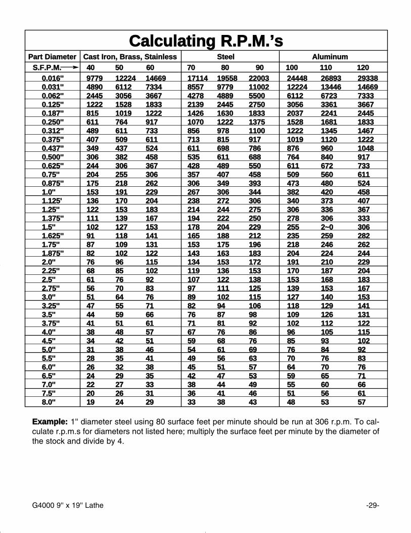
CCaallccuullaattiinngg RR..PP..MM..’’ssPPaarrtt DDiiaammeetteerr CCaasstt IIrroonn,, BBrraassss,, SSttaaiinnlleessss SStteeeell AAlluummiinnuumm
SS..FF..PP..MM.. 4400 5500 6600 7700 8800 9900 110000 111100 11220000..001166'''' 99777799 1122222244 1144666699 1177111144 1199555588 2222000033 2244444488 2266889933 229933338800..003311'''' 44889900 66111122 77333344 88555577 99777799 1111000022 1122222244 1133444466 114466669900..006622'''' 22444455 33005566 33666677 44227788 44888899 55550000 66111122 66772233 7733333300..112255'''' 11222222 11552288 11883333 22113399 22444455 22775500 33005566 33336611 3366667700..118877'''' 881155 11001199 11222222 11442266 11663300 11883333 22003377 22224411 2244445500..225500'''' 661111 776644 991177 11007700 11222222 11337755 11552288 11668811 1188333300..331122'''' 448899 661111 773333 885566 997788 11110000 11222222 11334455 1144667700..337755'''' 440077 550099 661111 771133 881155 991177 11001199 11112200 1122222200..443377'''' 334499 443377 552244 661111 669988 778866 887766 996600 1100448800..550000'''' 330066 338822 445588 553355 661111 668888 776644 884400 99117700..662255'''' 224444 330066 336677 442288 448899 555500 661111 667722 77333300..7755'''' 220044 225555 330066 335577 440077 445588 550099 556600 66111100..887755'''' 117755 221188 226622 330066 334499 339933 447733 448800 55224411..00'''' 115533 119911 222299 226677 330066 334444 338822 442200 44558811..112255'' 113366 117700 220044 223388 227722 330066 334400 337733 44007711..2255'''' 112222 115533 118833 221144 224444 227755 330066 333366 33667711..337755'''' 111111 113399 116677 119944 222222 225500 227788 330066 33333311..55'''' 110022 112277 115533 117788 220044 222299 225555 22~~00 33006611..662255'''' 9911 111188 114411 116655 118888 221122 223355 225599 22882211..7755'''' 8877 110099 113311 115533 117755 119966 221188 224466 22662211..887755'''' 8822 110022 112222 114433 116633 118833 220044 222244 22444422..00'''' 7766 9966 111155 113344 115533 117722 119911 221100 22229922..2255'''' 6688 8855 110022 111199 113366 115533 117700 118877 22004422..55'''' 6611 7766 9922 110077 112222 113388 115533 116688 11883322..7755'''' 5566 7700 8833 9977 111111 112255 113399 115533 11667733..00'''' 5511 6644 7766 8899 110022 111155 112277 114400 11553333..2255'''' 4477 5555 7711 8822 9944 110066 111188 112299 11441133..55'''' 4444 5599 6666 7766 8877 9988 110099 112266 11331133..7755'''' 4411 5511 6611 7711 8811 9922 110022 111122 11222244..00'''' 3388 4488 5577 6677 7766 8866 9966 110055 11115544..55'''' 3344 4422 5511 5599 6688 7766 8855 9933 11002255..00'''' 3311 3388 4466 5544 6611 6699 7766 8844 992255..55'''' 2288 3355 4411 4499 5566 6633 7700 7766 883366..00'''' 2266 3322 3388 4455 5511 5577 6644 7700 776666..55'''' 2244 2299 3355 4422 4477 5533 5599 6655 771177..00'''' 2222 2277 3333 3388 4444 4499 5555 6600 666677..55'''' 2200 2266 3311 3366 4411 4466 5511 5566 661188..00'''' 1199 2244 2299 3333 3388 4433 4488 5533 5577
EExxaammppllee:: 1'' diameter steel using 80 surface feet per minute should be run at 306 r.p.m. To cal-culate r.p.m.s for diameters not listed here; multiply the surface feet per minute by the diameter ofthe stock and divide by 4.
-30- G4000 9'' x 19'' Lathe

G4000 9'' x 19'' Lathe -31-
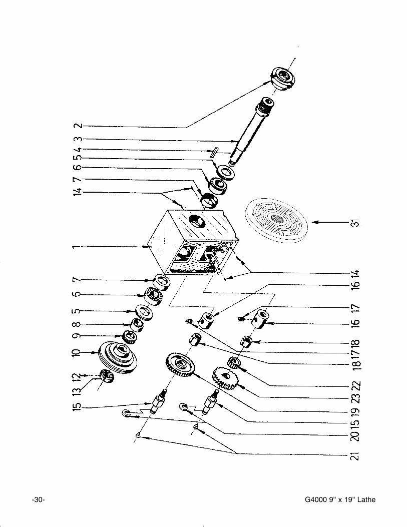
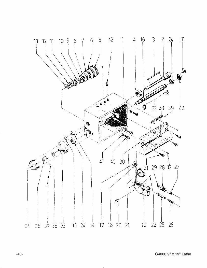
RREEFF PPAARRTT ## DDEESSCCRRIIPPTTIIOONN
01 P4000101 HEADSTOCK CASTING 02 P4000102 BACK PLATE FOR 3-JAW03 P4000103 SPINDLE 04 P4000104 KEY 05 P4000105 GASKET 06 P320007 BALL BEARING 32000707 P4000107 COVER 08 P4000108 SPACING RING 09 P4000109 GEAR (40T) 10 P4000110 PULLEY 12 PSS08M SET SCREW M4-0.7 x 5mm13 P4000113 SPANNER NUT14 PSS23M SET SCREW M4-0.7 x 10mm15 P4000115 SHAFT 16 P4000116 SPACING RING 17 PSS08M SET SCREW M4-0.7 x 5mm18 P4000405 BUSHING19 P4000119A GEAR 80T, METAL 20 P4000120 SPECIAL WASHER 21 P4000121 OIL PORT 22 P4000122 GEAR (40T) 23 P4000123 GEAR (28T) 24 PSB40 CAP SCREW M8-1.25 x 3525 P4000125 BACK PLATE 6''26 P4000126 4'' 3-JAW CHUCK 26A P4000126A CHUCK KEY- 3 JAW26B P4000126B REVERSE JAW 27 P4000127 6'' 4-JAW CHUCK 27A P4000127A CHUCK KEY- 4 JAW 29 P4000129 DEAD CENTER MT2 30 P4000130 DEAD CENTER MT3 31 P4000131 FACE PLATE
-32- G4000 9'' x 19'' Lathe

G4000 9'' x 19'' Lathe -33-
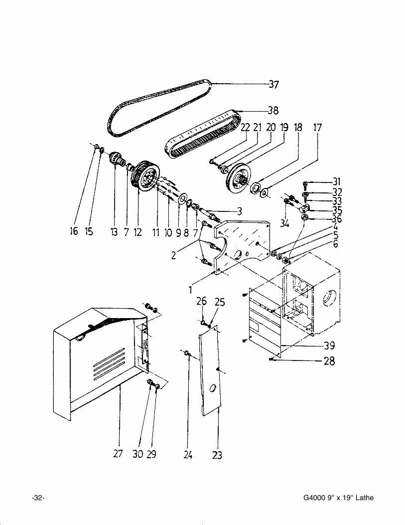
RREEFF PPAARRTT ## DDEESSCCRRIIPPTTIIOONN
01 P4000201 BRACKET PLATE 02 PSB15M CAP SCREW M5-.8 x 2003 P4000203 BELT PULLEY SHAFT04 PW05M FLAT WASHER 4mm05 PLW06M LOCK WASHER 10mm06 PN02M HEX NUT M10-1.507 P4000207 BUSHING 08 PR11M EXT. RETAINING RING 25mm09 P4000209 SPECIAL WASHER 10 P4000210 SPRING 11 P4000211 BALL 12 P4000212 PULLEY 13 P4000213 CLUTCH HUB 15 PR03M EXT. RETAINING RING 12mm16 P4000216 OIL PORT 17B P4000217B SPACER18B P4000218B COLLAR 19B P4000219B MOTOR PULLEY 20 P4000220 SPECIAL WASHER 21 PLW03M LOCK WASHER 6mm22 PSB06M CAP SCREW 23 P4000223 COVER PLATE 24 PSB33M CAP SCREW 25 PW02M FLAT WASHER 5mm26 PSB03M CAP SCREW M5-0.8 x 8mm27 P4000227 COVER W/ HINGE 28 PSB17M CAP SCREW M4-0.7 x 10mm29 PW03M FLAT WASHER 6MM30 PSB04M CAP SCREW M6-1.0 x 10mm31 PSB06M CAP SCREW M6-1.0 x 25mm32 PW03M FLAT WASHER 6mm33 P4000233 SPRING 34 PSB02M CAP SCREW M6-1.0 x 20mm35 P4000235 CLAMP BLOCK 36 PN01M HEX NUT M6-1.0 37 P4000237A V BELT M5 X 730 38 P4000238A TOOTH BELT 160 X L 050 39 P4000239 PLATE
-34- G4000 9'' x 19'' Lathe

G4000 9'' x 19'' Lathe -35-
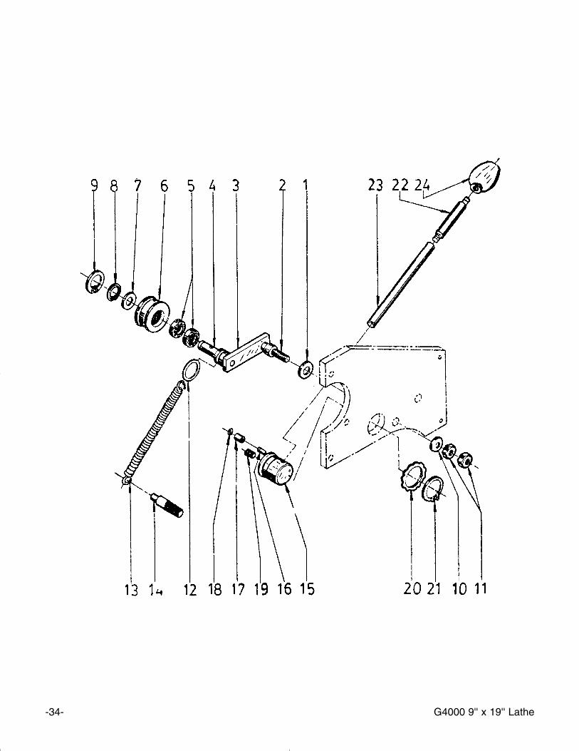
RREEFF PPAARRTT ## DDEESSCCRRIIPPTTIIOONN
01 P4000301 SPECIAL WASHER 02 P4000302 STUD BOLT 03 P4000303 AXLE BRACKET 04 P4000304 AXLE 05 P6001 BEARING 6001-2RS06 P4000306 ROLLER 07 P4000307 SPECIAL WASHER 08 PR03M EXT RETAINING RING12mm09 PR20M INT RETAINING RING 28mm10 PW04M FLAT WASHER 10mm11 PN02M HEX NUT M10-1.512 P4000312 SPECIAL WASHER
RREEFF PPAARRTT ## DDEESSCCRRIIPPTTIIOONN
13 P4000313 SPRING 14 P4000314 STUD BOLT 15 P4000315 TENSIONING CAM16 P4000316 PIN 17 P4000317 SLEEVE 18 PR04M EXT RETAINING RING 6mm19 P4000319 SET SCREW 20 P4000320 WAVY WASHER 21 P4000321 SNAP RING 22 P4000322 LEVER EXTENSION23 P4000323 LEVER 24 P4000324 KNOB
-36- G4000 9'' x 19'' Lathe

G4000 9'' x 19'' Lathe -37-
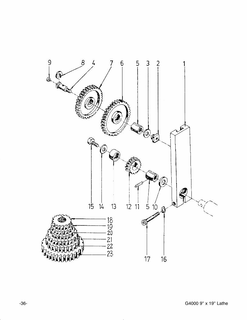
RREEFF PPAARRTT ## DDEESSCCRRIIPPTTIIOONN
01 P4000401 BRACKET 02 P4000402 T-NUT 03 PW03M FLAT WASHER 6mm04 P4000404 SHAFT 05 P4000405 BUSHING 06 P4000406 GEAR 127T 07 P4000407 GEAR 120T 08 P4000408 SPECIAL WASHER 09 P4000409 OIL PORT 10 PW04M FLAT WASHER 11 PRP19M ROLL PIN 4 X 14mm12 P4000412 GEAR 30T
RREEFF PPAARRTT ## DDEESSCCRRIIPPTTIIOONN
13 P4000413 SPACING RING 14 PW03M FLAT WASHER 6mm15 PSB04M CAP SCREW M6-1.0 x 10mm16 PLW03M LOCK WASHER 6mm17 PSB48M CAP SCREW M6-1.0 x 35mm18 P4000418 GEAR 28T 19 P4000419 GEAR 36T 20 P4000420 GEAR 42T 21 P4000421 GEAR 45T 22 P4000422 GEAR 60T 23 P4000423 GEAR 80T
-38- G4000 9'' x 19'' Lathe

G4000 9'' x 19'' Lathe -39-
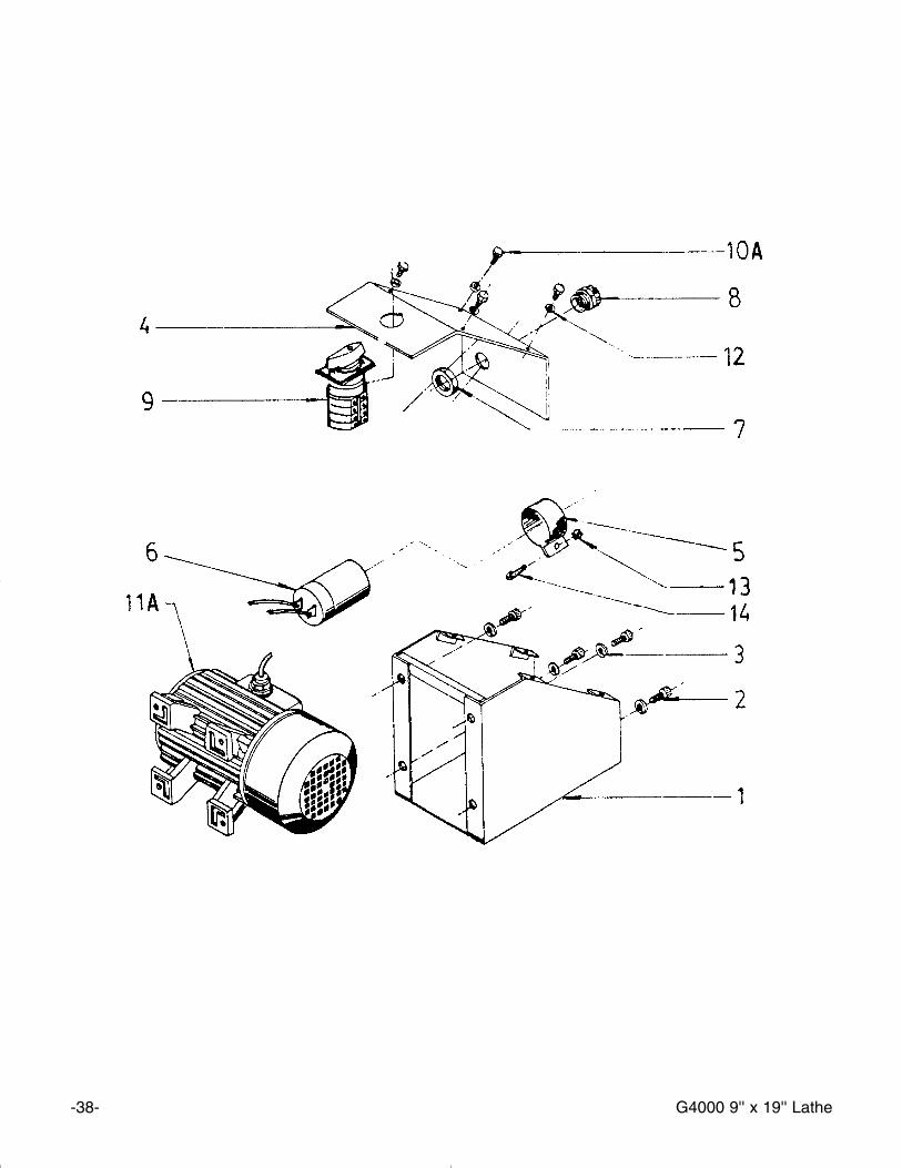
RREEFF PPAARRTT ## DDEESSCCRRIIPPTTIIOONN
01 P4000501 HOUSING 02 PS09M PHLP HD SCR M5-0.8 x 10mm03 PLW01 LOCK WASHER 5mm04 P4000504 COVER 05 P4000505 CAPACITOR COVER W/ CLIP 06 P4000506 CAPACITOR 60 MFD RED WIRE06A P4000506A CAPACITOR 400 BROWN WIRE
RREEFF PPAARRTT ## DDEESSCCRRIIPPTTIIOONN
07 P4000507 STRAIN RELIEF NUT 08 P4000508 STRAIN RELIEF 09 P4000509 SWITCH 10A PS09M PHLP HD SCR M5-0.8 x 10mm11A G5003 3⁄4 HP MOTOR 12 PLW01M LOCK WASHER 5mm13 PN06M HEX NUT M5-0.8 14 PSB50M CAP SCREW M5-0.8 x 10mm
-40- G4000 9'' x 19'' Lathe

G4000 9'' x 19'' Lathe -41-
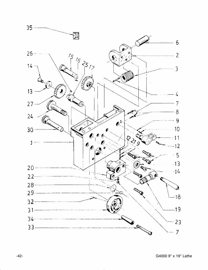
RREEFF PPAARRTT ## DDEESSCCRRIIPPTTIIOONN
01 P4000601 GEAR BOX CASTING 02 P4000602 SHAFT 03 PK13M KEY 5 x 5 x 70mm04 P4000604 BUSHING 05 P4000605 GEAR 28T 06 P4000606 GEAR 26T 07 P4000607 GEAR 24T 08 P4000608 GEAR 23T 09 P4000609 GEAR 22T 10 P4000610 GEAR 20T 11 P4000611 GEAR 19T 12 P4000612 GEAR 18T 13 P4000613 GEAR 16T 14 P4000614 BUSHING 15 PR06M EXT RETAINING RING 16mm16 P4000616 SHAFT 17 PK10M KEY 5 x 5 x 12mm18 P4000618 GEAR 16T 19 P4000619 SHIFT ARM 20 P4000620 SHAFT 21 P4000621 GEAR 36T 22 PSS05M SET SCREW M5-0.8 x 60mm23 PR05M EXT RETAINING RING 15mm24 P6202 BEARING 6202-2RS25 P4000625 LOCATING PIN 26 P4000626 SPRING 27 P4000627 BUSHING 28 P4000628 HANDLE 29 P4000629 CAP NUT 30 P4000630 FRONT COVER 31 PSB01M CAP SCREW M6-1.0 x 1632 P4000632 PIN 33 P4000633 BRACKET 34 PSB04M CAP SCREW M6-1.0 x 1035 PW04M FLAT WASHER 10mm36 P4000636 BUSHING 37 P4000637 PIN 38 P4000638 LABEL39 P4000639 RIVET 40 PSB14M CAP SCREW M8-1.25 x 20mm41 PLW04M LOCK WASHER42 P4000642 OIL CUP 43 P4000643 BEARING CAP
-42- G4000 9'' x 19'' Lathe
G4000 9'' x 19'' Lathe -43-

-44- G4000 9'' x 19'' Lathe
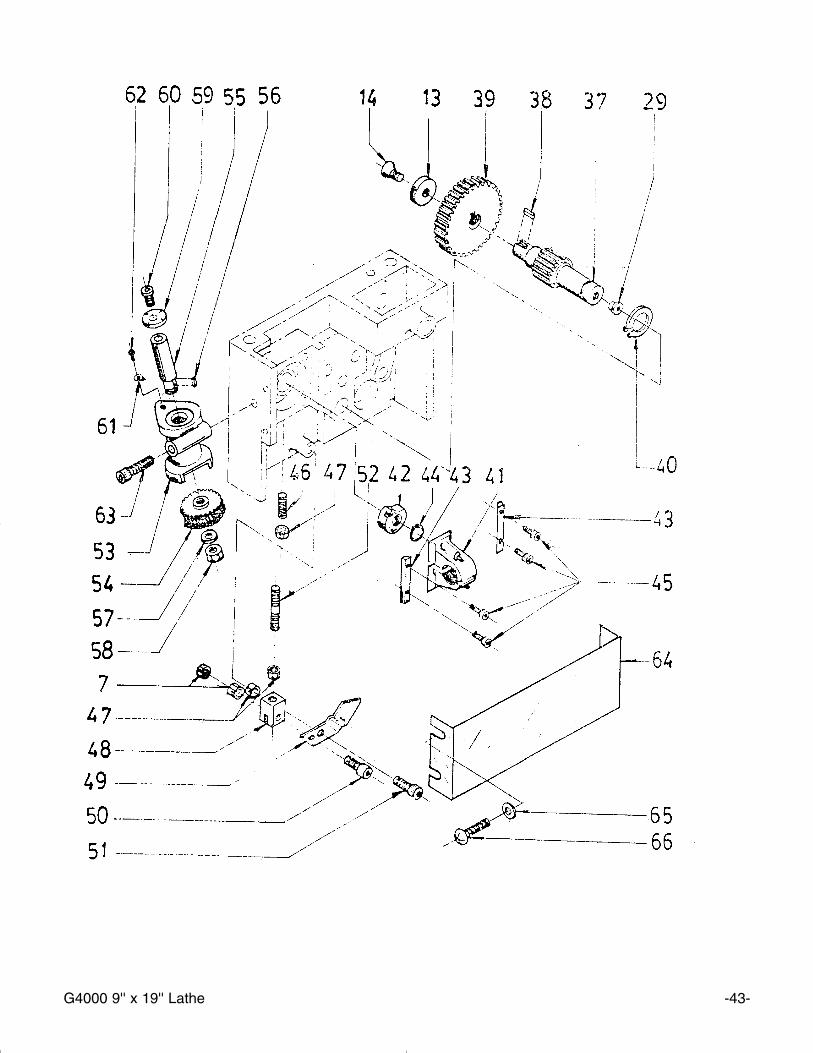
RREEFF PPAARRTT ## DDEESSCCRRIIPPTTIIOONN
01 P4000701 APRON CASTING 02 P4000702 BRACKET 03 P4000703 WORM 04 PK52M KEY 3 x 3 x 25mm05 PSB06M CAP SCREW M6-1.0 x 2506 P4000706 FEED SCREW 07 P4000707 NUT M4-0.708 PSS22M SET SCREW M4-.07 x 1209 P4000709 STEEL BALL 10 P4000710 SPRING 11 P4000711 HANDLE 12 PSS02M SET SCREW M6-1.0 x 16mm13 P4000713 WASHER 14 PFH04M FLAT HD SCR M6-1.0 x 8mm15 P4000715 GEAR 12T 16 P4000716 SPRING 17 P4000717 GEAR 43T 18 P4000718 HANDLE 19 P4000719 GEAR 13T 20 P4000720 BRACKET 21 P4000721 SPRING 22 PSS23M SET SCREW M4-0.7 x 10mm23 PSB07M CAP SCREW M6-1.0 x 30mm24 P4000724 GEAR 43T 25 P4000725 SHAFT 26 P4000726 KEY 27 P4000727 GEAR 41T 28 PR02M EXT RETAINING RING 14mm29 P4000729 OIL PORT 30 P4000730 GEAR 17T 31 P4000731 HAND WHEEL 32 PRP04M ROLL PIN 4 x 24mm33 P4000733 HANDLE SCREW 34 P4000734 HANDLE 35 P4000735 LABEL

G4000 9'' x 19'' Lathe -45-
RREEFF PPAARRTT ## DDEESSCCRRIIPPTTIIOONN
37 P1550637 GEAR 18T38 PK05M KEY 4 x 4 x 10mm39 P4000739 GEAR 42T 40 P4000740 RING 41 P4000741 HALF NUT 42 P4000742 LOCKING CAM 43 P4000743 GUIDE 44 P4000744 EXTENSION RING 45 PSB16M CAP SCREW M4-0.7 x 16mm46 PSS24M SET SCREW M5-0.8 x 25mm47 PN06M HEX NUT M4-0.748 P4000748 CONTROL BLOCK 49 P4000749 JOINT PLATE 50 PSB39M CAP SCREW M4-0.7 x 20mm51 PSB24M CAP SCREW M5-0.8 x 16mm52 P4000752 SCREW 53 P4000753 THREAD DIAL BODY 54 P4000754 WORM GEAR 64T 55 P4000755 SHAFT 56 PK39M KEY 3 x 3 x 10mm57 PLW04M LOCK WASHER 8mm58 PN03M HEX NUT M8-1.2559 P4000759 DIAL 60 P4000760 SCREW 61 P4000761 POINTER 62 P4000762 RIVET 63 PSB49M CAP SCREW M6-1.0 x 60mm64 P4000764 APRON COVER 65 PW05M FLAT WASHER 4mm66 PS07M PHLP HD SCR M4-0.7 x 8mm
-46- G4000 9'' x 19'' Lathe

G4000 9'' x 19'' Lathe -47-
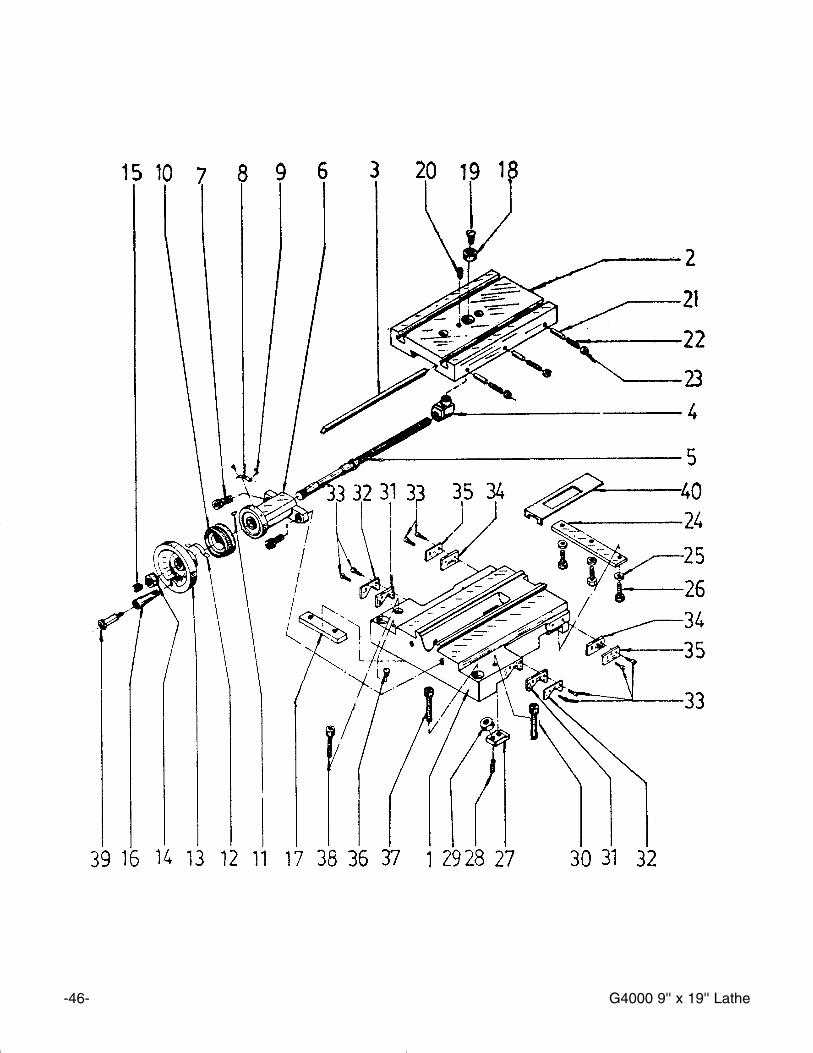
RREEFF PPAARRTT ## DDEESSCCRRIIPPTTIIOONN
01 P4000801 SADDLE 02 P4000802 CROSS SLIDE 03 P4000803 GIB 04 P4000804 CROSS SLIDE NUT 05 P4000805 LEAD SCREW 06 P4000806 BRACKET 07 PSB24M CAP SCREW M5-0.8 x 16mm08 P4000808 PLATE 09 P4000809 RIVET 2 X 5 10 P4000810 GRADUATED DIAL 11 P4000811 KEY 3X13 12 P4000812 SPRING 13 P4000731 HANDWHEEL14 P4000814 SPECIAL HEX NUT 15 PSS17M SET SCREW M8-1.25 x 6mm16 P4000734 HANDLE17 P4000817 SLIDE BLOCK 18 P4000818 BUSHING 19 PFH02M FLAT HD SCR M6-1.0 x12mm20 PSS04M SET SCREW M6-1.0 x 12mm21 P4000821 PIN 22 PSS22M SET SCREW M4-0.7 x 12mm23 PN04M HEX NUT M4-0.7 24 P4000824 APRON TENSION BAR25 PW03M FLAT WASHER M626 PSB01M CAP SCREW M6-1.0 x 16mm27 P4000827 CLIP 28 PSS25M SET SCREW M6-1.0 x 20mm29 PN01M HEX NUT M6-1.0 30 PSB06M CAP SCREW M6-1.0 x 25mm31 P4000831 WAY WIPER32 P4000832 WIPER CLAMP33 PS17M PHLP HD SCR M4-0.7 x 6mm34 P4000834 WAY COVER 35 P4000835 COVER MOUNT 36 P4000836 OIL PORT 37 PSB13M CAP SCR M8-1.25 x 30mm38 PSB06M CAP SCR M6-1.0 x 25mm39 P1550633 SPECIAL BOLT40 P4000840 CHIP GUARD
-48- G4000 9'' x 19'' Lathe

G4000 9'' x 19'' Lathe -49-
RREEFF PPAARRTT ## DDEESSCCRRIIPPTTIIOONN
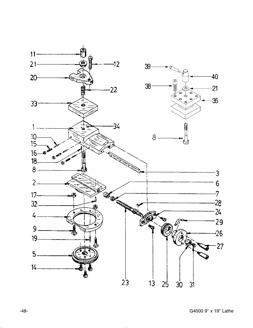
01 P4000901 COMPOUND SLIDE 02 P4000902 SWIVEL BASE 03 P4000903 GIB 04 P4000904 CLAMPING RING 05 P4000905 GRADUATED DIAL06 P4000906 SLIDE NUT 07 P4000907 ADJUSTING SCREW 08 P4000908 TOOL POST STUD 09 P4000909 T-SCREW 10 P4000910 PIN 11 P4000911 TOOL POST NUT 12 PB26M HEX BOLT M8-1.25 x 30mm13 PSB50M CAP SCREW M5-0.8 x 10mm14 PFH02M FLAT HD SCR M6-1.0 x 12mm15 PSS23M SET SCREW M4-0.7 x 10mm16 PN04M HEX NUT M4-0.717 PN01M HEX NUT M6-1.018 P4000918 LOCK PIN 3 X 8 19 P4000919 LOCK PIN 3 X 14 20 P4000920 TOOL CLAMP 21 PW01M FLAT WASHER 8mm22 P4000922 SPRING 23 P4000923 LEAD SCREW 24 P4000924 LEAD SCREW MOUNT 25 P4000925 GRADUATED DIAL 26 P4000926 HANDWHEEL 27 P4000927 HANDLE 28 PK39M KEY 3 x 3 x 10mm29 P4000929 CURSOR 30 P4000930 THREADED COLLAR 31 PSS17M SET SCREW M8-1.25 x 6mm32 P4000932 LOCK PIN 3X12 33 P4000933 PLATE 34 P4000934 PIN 35 P4000935 TOOL REST38 PSB13M CAP SCREW M8-1.25 x 30mm39 P4000939 LOCK HANDLE40 P4000940 LOCK NUT
-50- G4000 9'' x 19'' Lathe
RREEFF PPAARRTT ## DDEESSCCRRIIPPTTIIOONN
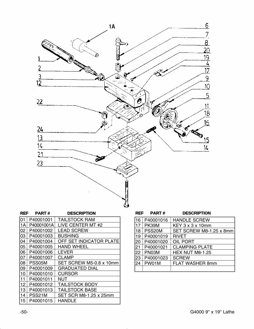
01 P40001001 TAILSTOCK RAM 1A P40001001A LIVE CENTER MT #202 P40001002 LEAD SCREW 03 P40001003 BUSHING 04 P40001004 OFF SET INDICATOR PLATE 05 P40001005 HAND WHEEL 06 P40001006 LEVER 07 P40001007 CLAMP 08 PSS05M SET SCREW M5-0.8 x 10mm09 P40001009 GRADUATED DIAL10 P40001010 CURSOR11 P40001011 NUT 12 P40001012 TAILSTOCK BODY13 P40001013 TAILSTOCK BASE14 PSS21M SET SCR M8-1.25 x 25mm15 P40001015 HANDLE
16 P40001016 HANDLE SCREW 17 PK39M KEY 3 x 3 x 10mm18 PSS20M SET SCREW M8-1.25 x 8mm19 P40001019 RIVET 20 P40001020 OIL PORT 21 P40001021 CLAMPING PLATE 22 PN03M HEX NUT M8-1.2523 P40001023 SCREW 24 PW01M FLAT WASHER 8mm
RREEFF PPAARRTT ## DDEESSCCRRIIPPTTIIOONN
G4000 9'' x 19'' Lathe -51-
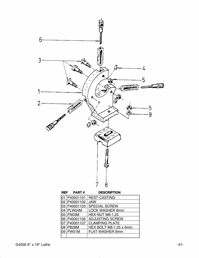
01 P40001101 REST CASTING 02 P40001102 JAW 03 P40001103 SPECIAL SCREW 04 PLW04M LOCK WASHER 8mm05 PN03M HEX NUT M8-1.25 06 P40001106 ADJUSTING SCREW 07 P40001107 CLAMPING PLATE 08 PB28M HEX BOLT M8-1.25 x 6mm09 PW01M FLAT WASHER 8mm
RREEFF PPAARRTT ## DDEESSCCRRIIPPTTIIOONN
-52- G4000 9'' x 19'' Lathe
RREEFF PPAARRTT ## DDEESSCCRRIIPPTTIIOONN
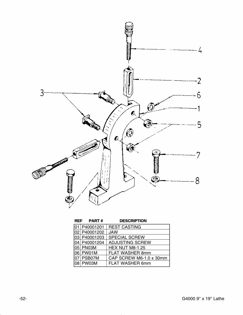
01 P40001201 REST CASTING 02 P40001202 JAW 03 P40001203 SPECIAL SCREW 04 P40001204 ADJUSTING SCREW 05 PN03M HEX NUT M8-1.2506 PW01M FLAT WASHER 8mm07 PSB07M CAP SCREW M6-1.0 x 30mm08 PW03M FLAT WASHER 6mm
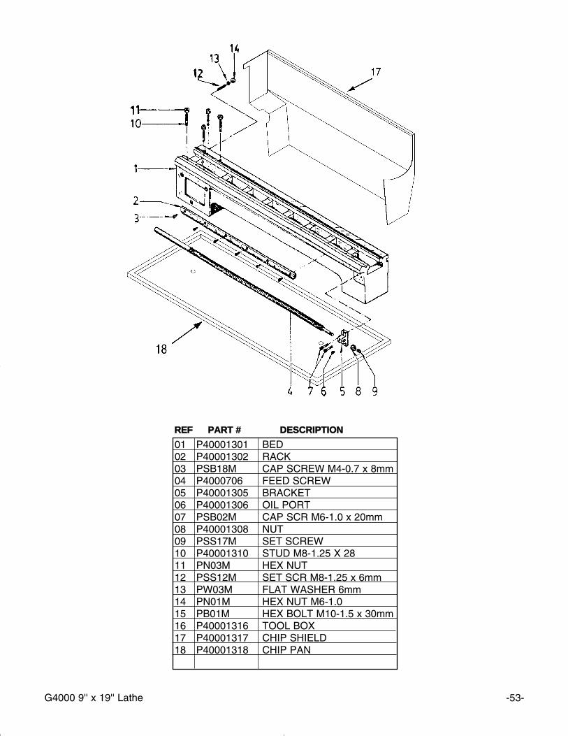
G4000 9'' x 19'' Lathe -53-
RREEFF PPAARRTT ## DDEESSCCRRIIPPTTIIOONN
01 P40001301 BED 02 P40001302 RACK 03 PSB18M CAP SCREW M4-0.7 x 8mm04 P4000706 FEED SCREW05 P40001305 BRACKET 06 P40001306 OIL PORT 07 PSB02M CAP SCR M6-1.0 x 20mm08 P40001308 NUT 09 PSS17M SET SCREW10 P40001310 STUD M8-1.25 X 28 11 PN03M HEX NUT12 PSS12M SET SCR M8-1.25 x 6mm13 PW03M FLAT WASHER 6mm14 PN01M HEX NUT M6-1.015 PB01M HEX BOLT M10-1.5 x 30mm16 P40001316 TOOL BOX 17 P40001317 CHIP SHIELD18 P40001318 CHIP PAN

-54- G4000 9'' x 19'' Lathe
Grizzly Imports, Inc. warrants every product it sells for a period of 11 yyeeaarr to the original purchaser from thedate of purchase. This warranty does not apply to defects due directly or indirectly to misuse, abuse, neg-ligence, accidents, repairs or alterations or lack of maintenance. This is Grizzly’s sole written warranty andany and all warranties that may be implied by law, including any merchantability or fitness, for any particu-lar purpose, are hereby limited to the duration of this written warranty. We do not warrant or represent thatthe merchandise complies with the provisions of any law or acts unless the manufacturer so warrants. Inno event shall Grizzly’s liability under this warranty exceed the purchase price paid for the product and anylegal actions brought against Grizzly shall be tried in the State of Washington, County of Whatcom.
We shall in no event be liable for death, injuries to persons or property or for incidental, contingent, spe-cial, or consequential damages arising from the use of our products.
To take advantage of this warranty, contact us by mail or phone and give us all the details. We will thenissue you a “Return Number’’, which must be clearly posted on the outside as well as the inside of the car-ton. We will not accept any item back without this number. Proof of purchase must accompany the mer-chandise.
The manufacturers reserve the right to change specifications at any time because they constantly strive toachieve better quality equipment. We make every effort to ensure that our products meet high quality anddurability standards and we hope you never need to use this warranty.
Please feel free to write or call us if you have any questions about the machine or the manual.
Thank you again for your business and continued support. We hope to serve you again soon.
WWAARRRRAANNTTYY AANNDD RREETTUURRNNSS

WWAARRRRAANNTTYY CCAARRDDNAME_______________________________________________ PHONE NUMBER___________________STREET________________________________________________________________________________CITY_______________________________STATE_________ZIP ___________________________________MODEL# G4000 9'' x 19'' Lathe PURCHASED FROM GRIZZLY, BELLINGHAM, WA
OR WILLIAMSPORT, PA INVOICE#_________________
The following information is given on a voluntary basis. This information will be used for marketing purposes to helpGrizzly develop better products. Your name will be included in our mailing lliisstt only. It will not be sold to other com-panies. of course, all information is strictly confidential.
11.. How did you find out about us?
__Advertisement __Friend __Other______________________Catalog __Card deck
22.. Do you think your machine represents good value? __YES __NO
33.. Would you allow us to use your name as a reference for Grizzly customers in your area? __YES __NO((NNoottee:: Your nnaammee will be used a maximum of three ttiimmeess..))
44.. To which of the following publications do you subscribe? Check all that apply.
__Home Shop Machinist __Rifle Magazine Other ________________ __Projects in Metal __Hand Loader Magazine__Modeltec __Precision Shooter__Live Steam __RC Modeler__Shotgun News __Model Airplane News
55.. What is your annual household income?
__$20,000-$30,000 __$50,001-$60,000 __$80,000-$90,000__$30,001-$40,000 __$60,001-$70,000 __+$90,000__$40,001-$50,000 __$70,001-$80,000
66.. To which age group do you belong?
__20-30 __41-50__61-70__31-40 __51-60__+70
77.. Which of the following machines or accessories do you own? Check all that apply.
__Engine Lathe __Abrasive Cutoff __Sheet Metal Machine__Band Saw (Metal) __Arc Welder __Other _____________________________ __Band Saw (Wood) __Oxy/Ac. Outfit__Milling Machine __Air Compressor__Bench Grinder __Drill Press
88.. How many of the machines you checked in Question 7 are Grizzly machines? ______________________
99.. Which of the following tooling and accessories do you own? Check all that apply.
__Milling Vises __Collet Closer __Digital Readout__Indexing Head __Taper Attachment __Tool Post Grinder__Rotary Table __Boring Head __Other _________________________________________
1100.. In the space below, list three tools you would like Grizzly to carry.
1111.. Of all the mail order metalworking company’s you have purchased from, how do you rate Grizzly in terms of over-all customer satisfaction?
__The best __Above average __Average__Below average __The worst
1122.. Comments________________________________________________________________________________
Cut
alo
ng d
otte
d lin
e

FOLD ALONG DOTTED LINE
FOLD ALONG DOTTED LINE
GGRRIIZZZZLLYY IINNDDUUSSTTRRIIAALL,, IINNCC..PP..OO.. BBOOXX 22006699BBEELLLLIINNGGHHAAMM,, WWAA 9988222277--22006699
PlaceStampHere
TAPE ALONG EDGES--PLEASE DO NOT STAPLE
Name_______________________________
Street_______________________________
City______________State______Zip______
Send a Grizzly Catalog to a friend:
Related Documents