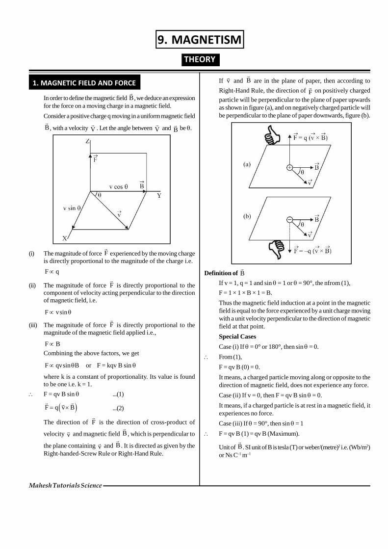
1. MAGNETIC FIELD AND FORCE In order to define the magnetic field B , we deduce an expression for the force on a moving charge in a magnetic field. Consider a positive charge q moving in a uniform magnetic field B , with a velocity V . Let the angle between V and B be . (i) The magnitude of force F experienced by the moving charge is directly proportional to the magnitude of the charge i.e. F q (ii) The magnitude of force F is directly proportional to the component of velocity acting perpendicular to the direction of magnetic field, i.e. F vsin (iii) The magnitude of force F is directly proportional to the magnitude of the magnetic field applied i.e., F B Combining the above factors, we get F qvsin B or F = kqv B sin where k is a constant of proportionality. Its value is found to be one i.e. k = 1. F = qv B sin ...(1) F qv B ...(2) The direction of F is the direction of cross-product of velocity v and magnetic field B , which is perpendicular to the plane containing v and B . It is directed as given by the Right-handed-Screw Rule or Right-Hand Rule. If v and B are in the plane of paper, then according to Right-Hand Rule, the direction of F on positively charged particle will be perpendicular to the plane of paper upwards as shown in figure (a), and on negatively charged particle will be perpendicular to the plane of paper downwards, figure (b). Definition of B If v = 1, q = 1 and sin = 1 or = 90°, the nfrom (1), F = 1 × 1 × B × 1 = B. Thus the magnetic field induction at a point in the magnetic field is equal to the force experienced by a unit charge moving with a unit velocity perpendicular to the direction of magnetic field at that point. Special Cases Case (i) If = 0° or 180°, then sin = 0. From (1), F = qv B (0) = 0. It means, a charged particle moving along or opposite to the direction of magnetic field, does not experience any force. Case (ii) If v = 0, then F = qv B sin = 0. It means, if a charged particle is at rest in a magnetic field, it experiences no force. Case (iii) If = 90°, then sin = 1 F = qv B (1) = qv B (Maximum). Unit of B . SI unit of B is tesla (T) or weber/(metre) 2 i.e. (Wb/m 2 ) or Ns C –1 m –1 Mahesh Tutorials Science THEORY 9. MAGNETISM

Welcome message from author
This document is posted to help you gain knowledge. Please leave a comment to let me know what you think about it! Share it to your friends and learn new things together.
Transcript
1. MAGNETIC FIELD AND FORCE
In order to define the magnetic field B
, we deduce an expressionfor the force on a moving charge in a magnetic field.
Consider a positive charge q moving in a uniform magnetic field
B
, with a velocity V
. Let the angle between V
and B
be .
(i) The magnitude of force F
experienced by the moving chargeis directly proportional to the magnitude of the charge i.e.
F q
(ii) The magnitude of force F
is directly proportional to thecomponent of velocity acting perpendicular to the directionof magnetic field, i.e.
F vsin
(iii) The magnitude of force F
is directly proportional to themagnitude of the magnetic field applied i.e.,
F BCombining the above factors, we get
F qvsin B or F = kqv B sin
where k is a constant of proportionality. Its value is foundto be one i.e. k = 1.
F = qv B sin ...(1)
F q v B
...(2)
The direction of F
is the direction of cross-product of
velocity v and magnetic field B
, which is perpendicular to
the plane containing v and B
. It is directed as given by the
Right-handed-Screw Rule or Right-Hand Rule.
If v
and B
are in the plane of paper, then according to
Right-Hand Rule, the direction of F
on positively charged
particle will be perpendicular to the plane of paper upwardsas shown in figure (a), and on negatively charged particle willbe perpendicular to the plane of paper downwards, figure (b).
Definition of B
If v = 1, q = 1 and sin = 1 or = 90°, the nfrom (1),
F = 1 × 1 × B × 1 = B.
Thus the magnetic field induction at a point in the magneticfield is equal to the force experienced by a unit charge movingwith a unit velocity perpendicular to the direction of magneticfield at that point.
Special Cases
Case (i) If = 0° or 180°, then sin = 0.
From (1),
F = qv B (0) = 0.
It means, a charged particle moving along or opposite to thedirection of magnetic field, does not experience any force.
Case (ii) If v = 0, then F = qv B sin = 0.
It means, if a charged particle is at rest in a magnetic field, itexperiences no force.
Case (iii) If = 90°, then sin = 1
F = qv B (1) = qv B (Maximum).
Unit of B
. SI unit of B is tesla (T) or weber/(metre)2 i.e. (Wb/m2)or Ns C–1 m–1
Mahesh Tutorials Science
THEORY
9. MAGNETISM
Thus, the magnetic field induction at a point is said to beone tesla if a charge of one coulomb while moving at rightangle to a magnetic field, with a velocity of 1 ms–1 experiencesa force of 1 newton, at that point.
2
1 21
MLTDimensions of B MA T
AT LT
2. LORENTZ FORCE
The force experienced by a charged particle moving in spacewhere both electric and magnetic fields exist is called Lorentzforce.
Force due to electric field. When a charged particle carrying
charge +q is subjected to an electric field of strength E
, it
experiences a force given by
eF qE
...(5)
whose direction is the same as that of E
.
Force due to magnetic field. If the charged particle is moving
in a magnetic field B
, with a velocity v it experiences a
force given by
mF q v B
The direction of this force is in the direction of v B i.e.
perpendicular to the plane contaning v and B
and is
directed as given by Right hand screw rule.
Due to both the electric and magnetic fields, the total forceexperienced by the charged particle will be given by
e mF F F qE q v B q E v B
F q E v B
...(6)
This is called Lorentz force.
Special cases
Case I. When v, E and B
, all the three are collinear.. In
this situation, the charged particle is moving parallel orantiparallel to the fields, the magnetic force on the chargedparticle is zero. The electric force on the charged particle
will produce accelerationqE
am
,
along the direction of electricl field. As a result of this, therewill be change in the speed of charged particle along thedirection of the field. In this situation there will be no changein the direction of motion of the charged particle but, the
speed, velocity, momentum and kinetic energy of chargedparticle will change.
Case II. When v, E and B
are mutually perpendicular to
each other. In this situation if E
and B
are such that
e mF F F 0
, then acceleration in the particle,
Fa 0
m
. It means the particle will pass through the fields
without any change in its velocity. Here, Fe = F
m so qE = q v B
or v = E/B.
This concept has been used in velocity-selector to get acharged beam having a definite velocity.
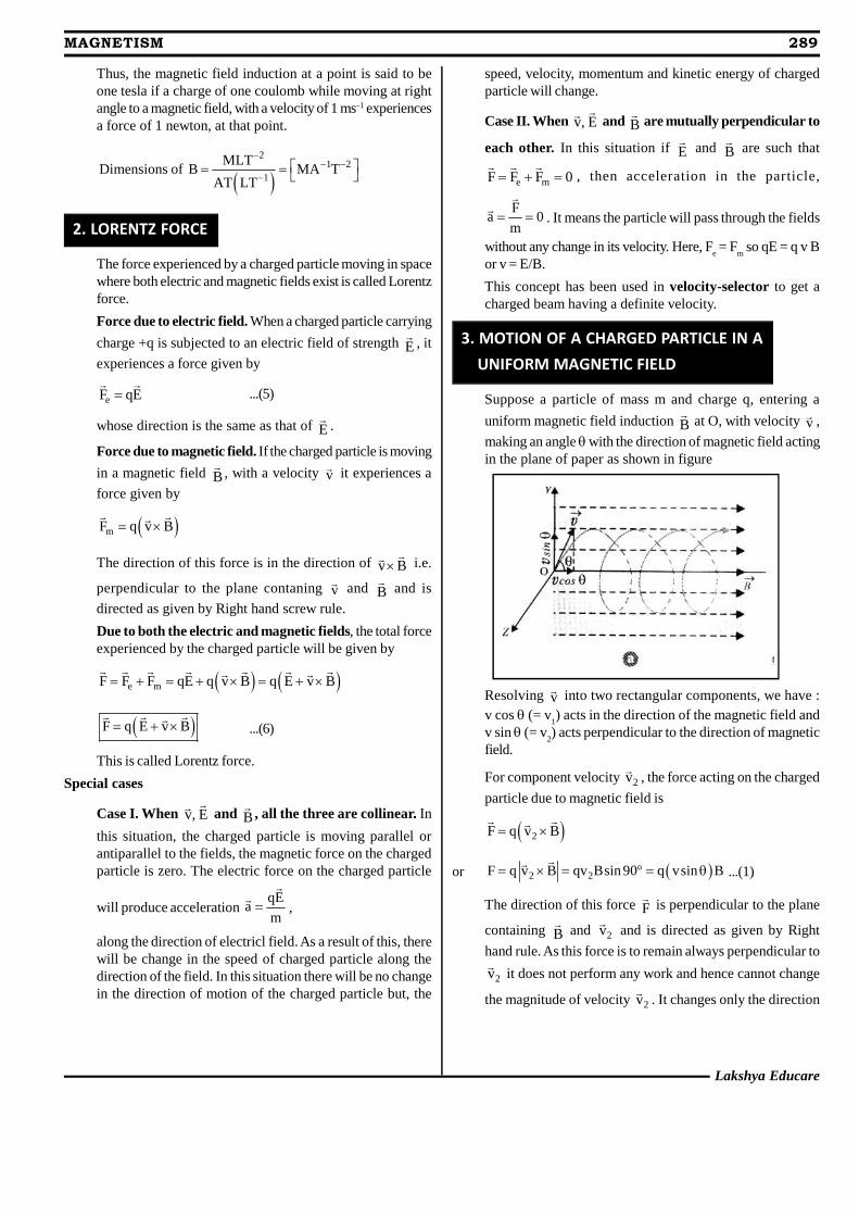
3. MOTION OF A CHARGED PARTICLE IN A UNIFORM MAGNETIC FIELD
Suppose a particle of mass m and charge q, entering a
uniform magnetic field induction B
at O, with velocity v ,
making an angle with the direction of magnetic field actingin the plane of paper as shown in figure
Resolving v into two rectangular components, we have :
v cos (= v1) acts in the direction of the magnetic field and
v sin (= v2) acts perpendicular to the direction of magnetic
field.
For component velocity 2v
, the force acting on the charged
particle due to magnetic field is
2F q v B
or 2 2F q v B qv Bsin 90 q vsin B
...(1)
The direction of this force F
is perpendicular to the plane
containing B
and 2v
and is directed as given by Right
hand rule. As this force is to remain always perpendicular to
2v
it does not perform any work and hence cannot change
the magnitude of velocity 2v
. It changes only the direction
Lakshya Educare
MAGNETISM 289
290 MAGNETISM
Mahesh Tutorials Science
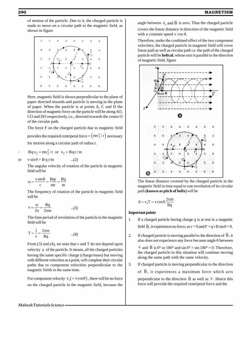
of motion of the particle. Due to it, the charged particle ismade to move on a circular path in the magnetic field, asshown in figure
Here, magnetic field is shown perpendicular to the plane ofpaper directed inwards and particle is moving in the planeof paper. When the particle is at points A, C and D thedirection of magnetic force on the particle will be along AO,CO and DO respectively, i.e., directed towards the centre Oof the circular path.
The force F on the charged particle due to magnetic field
provides the required centripetal force = 22mv / r necessary
for motion along a circular path of radius r.
22 2 2Bq v mv / r or v Bq r / m
or v sin = B q r/m ...(2)
The angular velocity of rotation of the particle in magneticfield will be
vsin Bqr Bq
r mr m
The frequency of rotation of the particle in magnetic fieldwill be
Bqv
2 2 m
...(3)
The time period of revolution of the particle in the magneticfield will be
1 2 mT
v Bq
...(4)
From (3) and (4), we note that v and T do not depend uponvelocity v
of the particle. It means, all the charged particleshaving the same specific charge (charge/mass) but movingwith different velocities at a point, will complete their circularpaths due to component velocities perpendicular to themagnetic fields in the same time.
For component velocity 1v vcos , there will be no force
on the charged particle in the magnetic field, because the
angle between 1v and B
is zero. Thus the charged particle
covers the linear distance in direction of the magnetic fieldwith a constant speed v cos .
Therefore, under the combined effect of the two componentvelocities, the charged particle in magnetic field will coverlinear path as well as circular path i.e. the path of the chargedparticle will be helical, whose axis is parallel to the directionof magnetic field, figure
The linear distance covered by the charged particle in themagnetic field in time equal to one revolution of its circularpath (known as pitch of helix) will be
12 m
d v T vcosBq
Important points
1. If a charged particle having charge q is at rest in a magnetic
field B
, it experiences no force; as v = 0 and F = q v B sin = 0.
2. If charged particle is moving parallel to the direction of B
, italso does not experience any force because angle between
v
and B
is 0° or 180° and sin 0° = sin 180° = 0. Therefore,the charged particle in this situation will continue movingalong the same path with the same velocity.
3. If charged particle is moving perpendicular to the direction
of B
, it experiences a maximum force which acts
perpendicular to the direction B
as well as v
. Hence thisforce will provide the required centripetal force and the
Lakshya Educare
MAGNETISM 291
charged particle will describe a circular path in the magnetic
field of radius r, given by2mv
Bqvr .
4. MOTION IN COMBINED ELECTRON AND MAGNETIC FIELDS
4.1 Velocity Filter
Velocity filter is an arrangement of cross electric andmagnetic fields in a region which helps us to select from abeam, charged particles of the given velocity irrespective oftheir charge and mass.
A velocity selector consists of two slits S1 and S
2 held parallel
to each other, with common axis, some distance apart. In theregion between the slits, uniform electric and magnetic fieldsare applied, perpendicular to each other as well as to theaxis of slits, as shown in figure. When a beam of chargedparticles of different charges and masses after passing
through slit S1 enters the region of crossed electric field E
and magnetic field B
, each particle experiences a force due
to these fields. Those particles which are moving with thevelocity v, irrespective of their mass and charge, the forceon each such particle due to electric field (qE) is equal andopposite to the force due to magnetic field (q v B), then
q E = q v B or v = E/B
Such particles will go undeviated and filtered out of theregion through the slit S
2. Therefore, the particles emerging
from slit S2 will have the same velocity even though their
charge and mass may be different.
The velocity filter is used in mass spectrograph which helpsto find the mass and specific charge (charge/mass) of thecharged particle.
4.2 Cyclotron
A cyclotron is a device developed by Lawrence andLivingstone by which the positively charged particles likeproton, deutron, alpha particle etc. can be accelerated.
Principle. The working of the cyclotron is based on the factthat a positively charged particle can be accelerated to a
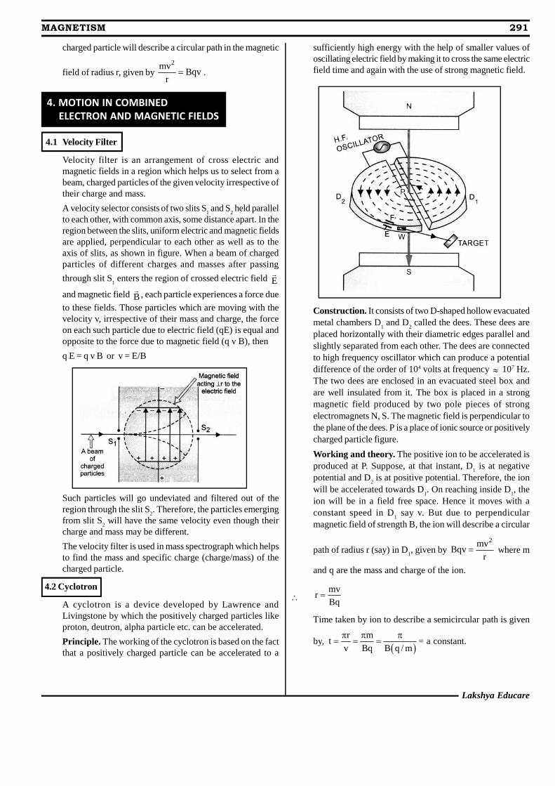
sufficiently high energy with the help of smaller values ofoscillating electric field by making it to cross the same electricfield time and again with the use of strong magnetic field.
Construction. It consists of two D-shaped hollow evacuatedmetal chambers D
1 and D
2 called the dees. These dees are
placed horizontally with their diametric edges parallel andslightly separated from each other. The dees are connectedto high frequency oscillator which can produce a potentialdifference of the order of 104 volts at frequency 107 Hz.The two dees are enclosed in an evacuated steel box andare well insulated from it. The box is placed in a strongmagnetic field produced by two pole pieces of strongelectromagnets N, S. The magnetic field is perpendicular tothe plane of the dees. P is a place of ionic source or positivelycharged particle figure.
Working and theory. The positive ion to be accelerated isproduced at P. Suppose, at that instant, D
1 is at negative
potential and D2 is at positive potential. Therefore, the ion
will be accelerated towards D1. On reaching inside D
1, the
ion will be in a field free space. Hence it moves with aconstant speed in D
1 say v. But due to perpendicular
magnetic field of strength B, the ion will describe a circular
path of radius r (say) in D1, given by
2mvBqv
r where m
and q are the mass and charge of the ion.
mv
rBq
Time taken by ion to describe a semicircular path is given
by,
r mt
v Bq B q / m
= a constant.
292 MAGNETISM
Mahesh Tutorials Science
This time is independent of both the speed of the ion andradius of the circular path. In case the time during whichthe positive ion describes a semicircular path is equal to thetime during which half cycle of electric oscillator is completed,then as the ion arrives in the gap between the two dees, thepolarity of the two dees is reversed i.e. D
1 becomes positive
and D2 negative. Then, the positive ion is accelerated
towards D2 and it enters D
2 with greater speed which remains
constant in D2. The ion will describe a semicircular path of
greater radius due to perpendicular magnetic field and againwill arrive in a gap between the two dees exactly at theinstant, the polarity of the two dees is reversed. Thus, thepositive ion will go on accelerating every time it comes intothe gap between the dees and will go on describing circularpath of greater and greater radius with greater and greaterspeed and finally acquires a sufficiently high energy. Theaccelerated ion can be removed out of the dees from windowW, by applying the electric field across the deflecting platesE and F.
Maximum Energy of positive ion
Let v0, r
0 = maximum velocity and maximum radius of the
circular path followed by the positive ion in cyclotron.
Then,20 0
0 00
mv BqrBqv or v
r m
2
2 00
Bqr1 1Max. K.E. mv m
2 2 m
2 2 20B q r
2m
Cyclotron Frequency
If T is the time period of oscillating electric field then
T = 2t = 2 m/Bq
The cyclotron frequency is given by1 Bq
vT 2 m
It is also known as magnetic resonance frequency.
The cyclotron angular frequency is given by
c 2 v Bq / m
5. FORCE ON A CURRENT CARRYING CONDUCTOR PLACED IN A MAGNETIC FIELD
Expression for the force acting on the conductor carryingcurrent placed in a magnetic field
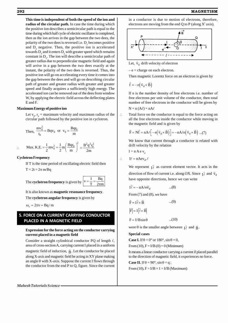
Consider a straight cylindrical conductor PQ of length ,area of cross-section A, carrying current I placed in a uniform
magnetic field of induction, B
. Let the conductor be placed
along X-axis and magnetic field be acting in XY plane makingan angle with X-axis. Suppose the current I flows throughthe conductor from the end P to Q, figure. Since the current
in a conductor is due to motion of electrons, therefore,electrons are moving from the end Q to P (along X’ axis).
Let, dv
drift velocity of electron
– e = charge on each electron.Then magnetic Lorentz force on an electron is given by
df e v B
If n is the number density of free electrons i.e. number offree electrons per unit volume of the conductor, then totalnumber of free electrons in the conductor will be given by
N = n (A) = nA Total force on the conductor is equal to the force acting on
all the free electrons inside the conductor while moving inthe magnetic field and is given by
d dF Nf nA e v B nA e v B ...(7)
We know that current through a conductor is related withdrift velocity by the relation
I = n A e vd
dI nAev .
We represent I as current element vector. It acts in the
direction of flow of current i.e. along OX. Since I and dv
have opposite directions, hence we can write
dI nA ev ...(8)
From (7) and (8), we have
F I B ...(9)
F I B
F I Bsin ...(10)
were is the smaller angle between I and B
.
Special cases
Case I. If = 0° or 180°, sin = 0,
From (10), F = IB (0) = 0 (Minimum)
It means a linear conductor carrying a current if placed parallelto the direction of magnetic field, it experiences no force.
Case II. If = 90°, sin = q ;
From (10), F = IB × 1 = IB (Maximum)
Lakshya Educare
MAGNETISM 293
It means a linear conductor carrying current if placedperpendicular to the direction of magnetic field, it experiencesmaximum force. The direction of which can be given byRight handed screw rule.
6. TORQUE ON A CURRENT CARRYING COIL IN A MAGNETIC FIELD
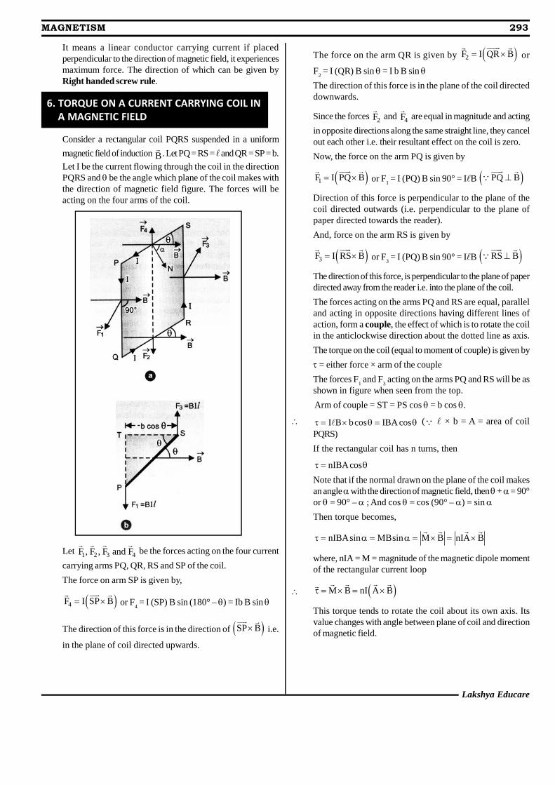
Consider a rectangular coil PQRS suspended in a uniform
magnetic field of induction B
. Let PQ = RS = and QR = SP = b.
Let I be the current flowing through the coil in the directionPQRS and be the angle which plane of the coil makes withthe direction of magnetic field figure. The forces will beacting on the four arms of the coil.
Let 1 2 3 4F , F , F and F
be the forces acting on the four current
carrying arms PQ, QR, RS and SP of the coil.
The force on arm SP is given by,
4F I SP B
or F4 = I (SP) B sin (180° – ) = Ib B sin
The direction of this force is in the direction of SP B
i.e.
in the plane of coil directed upwards.
The force on the arm QR is given by 2F I QR B
or
F2 = I (QR) B sin = I b B sin
The direction of this force is in the plane of the coil directeddownwards.
Since the forces 2F
and 4F
are equal in magnitude and acting
in opposite directions along the same straight line, they cancelout each other i.e. their resultant effect on the coil is zero.
Now, the force on the arm PQ is given by
1F I PQ B
or F1 = I (PQ) B sin 90° = IB PQ B
Direction of this force is perpendicular to the plane of thecoil directed outwards (i.e. perpendicular to the plane ofpaper directed towards the reader).
And, force on the arm RS is given by
3F I RS B
or F3 = I (PQ) B sin 90° = IB RS B
The direction of this force, is perpendicular to the plane of paperdirected away from the reader i.e. into the plane of the coil.
The forces acting on the arms PQ and RS are equal, paralleland acting in opposite directions having different lines ofaction, form a couple, the effect of which is to rotate the coilin the anticlockwise direction about the dotted line as axis.
The torque on the coil (equal to moment of couple) is given by
= either force × arm of the couple
The forces F1 and F
3 acting on the arms PQ and RS will be as
shown in figure when seen from the top.
Arm of couple = ST = PS cos = b cos .
I B bcos IBA cos ( × b = A = area of coilPQRS)
If the rectangular coil has n turns, then
nIBAcos
Note that if the normal drawn on the plane of the coil makesan angle with the direction of magnetic field, then+ = 90°or = 90° – ; And cos = cos (90° – ) = sin
Then torque becomes,
nIBAsin MBsin M B nIA B
where, nIA = M = magnitude of the magnetic dipole momentof the rectangular current loop
M B nI A B
This torque tends to rotate the coil about its own axis. Itsvalue changes with angle between plane of coil and directionof magnetic field.
294 MAGNETISM
Mahesh Tutorials Science
Special cases 1.
If the coil is set with its plane parallel to the direction ofmagnetic field B, then
0 and cos 1
Torque, = nIBA (1) = nIBA (Maximum)
This is the case with a radial field.
2. If the coil is set with its plane perpendicular to the directionof magentic field B, then = 90° and cos = 0
Torque, = nIBA (0) = 0 (Minimum)
7. MOVING COIL GALVANOMETER
Moving coil galvanometer is an instrument used for detectionand measurement of small electric currents.
Principle. Its working is based on the fact that when a currentcarrying coil is placed in a magnetic field, it experiences a torque.
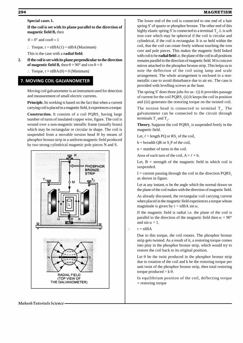
Construction. It consists of a coil PQRS1 having large
number of turns of insulated copper wire, figure. The coil iswound over a non-magnetic metallic frame (usually brass)which may be rectangular or circular in shape. The coil issuspended from a movable torsion head H by means ofphosphor bronze strip in a uniform magnetic field producedby two strong cylindrical magnetic pole pieces N and S.
The lower end of the coil is connected to one end of a hairspring S’ of quartz or phosphor bronze. The other end of thishighly elastic spring S’ is connected to a terminal T
2. L is soft
iron core which may be spherical if the coil is circular andcylindrical, if the coil is rectangular. It is so held within thecoil, that the coil can rotate freely without touching the ironcore and pole pieces. This makes the magnetic field linkedwith coil to be radial field i.e. the plane of the coil in all positionsremains parallel to the direction of magnetic field. M is concavemirror attached to the phosphor bronze strip. This helps us tonote the deflection of the coil using lamp and scalearrangement. The whole arrangement is enclosed in a non-metallic case to avoid disturbance due to air etc. The case isprovided with levelling screws at the base.
The spring S’ does three jobs for us : (i) It provides passageof current for the coil PQRS
1 (ii) It keeps the coil in position
and (iii) generates the restoring torque on the twisted coil.
The torsion head is connected to terminal T1. The
galvanometer can be connected to the circuit throughterminals T
1 and T
2.
Theory. Suppose the coil PQRS1 is suspended freely in the
magnetic field.
Let, = length PQ or RS1 of the coil,
b = breadth QR or S1P of the coil,
n = number of turns in the coil.
Area of each turn of the coil, A = × b.
Let, B = strength of the magnetic field in which coil issuspended.
I = current passing through the coil in the direction PQRS1
as shown in figure.
Let at any instant, be the angle which the normal drawn onthe plane of the coil makes with the direction of magnetic field.
As already discussed, the rectangular coil carrying currentwhen placed in the magnetic field experiences a torque whosemagnitude is given by = nIBA sin .
If the magnetic field is radial i.e. the plane of the coil isparallel to the direction of the magnetic field then = 90°and sin = 1.
= nIBA
Due to this torque, the coil rotates. The phosphor bronzestrip gets twisted. As a result of it, a restoring torque comesinto play in the phosphor bronze strip, which would try torestore the coil back to its original position.
Let be the twist produced in the phosphor bronze stripdue to rotation of the coil and k be the restoring torque perunit twist of the phosphor bronze strip, then total restoringtorque produced = k .
In equilibrium position of the coil, deflecting torque= restoring torque
Lakshya Educare
MAGNETISM 295
nIBA = k
ork
I or I GnBA
wherek
G anBA
constant for a galvanometer. It is
known as galvanometer constant.
Hence, I
It means, the deflection produced is proportional to thecurrent flowing through the galvanometer. Such agalvanometer has a linear scale.
Current sensitivity of a galvanometer is defined as thedeflection produced in the galvanometer when a unit currentflows through it.
If is the deflection in the galvanometer when current I ispassed through it, then
Current sensitivity,
snBA
II k
kI
nBA
The unit of current sensitivity is rad. A–1 or div. A–1.
Voltage sensitivity of a galvanometer is defined as thedeflection produced in the galvanometer when a unit voltageis applied across the two terminals of the galvanometer.
Let, V = voltage applied across the two terminals of thegalvanometer,
= deflection produced in the galvanometer.
Then, voltage sensitivity, VS = /V
If R = resistance of the galvanometer, I = current through it.Then V = IR
Voltage sensitivity,
SS
InBAV
IR kR R
the unit of VS is rad V–1 or div. V–1.
Conditions for a sensitive galvanometer
A galvanometer is said to be very sensitive if it shows largedeflection even when a small current is passed through it.
From the theory of galvanometer,nBA
Ik
For a given value of I, will be large if nBA/k is large. It is soif (a) n is large (b) B is large (c) A is large and (d) k is small.
(a) The value of n can not be increased beyond a certain limitbecause it results in an increase of the resistance of thegalvanometer and also makes the galvanometer bulky. Thistends to decrease the sensitivity. Hence n can not beincreased beyond a limit.
(b) The value of B can be increased by using a strong horseshoe magnet.
(c) The value of A can not be increased beyond a limit becausein that case the coil will not be in a uniform magnetic field.Moreover, it will make the galvanometer bulky andunmanageable.
(d) The value of k can be decreased. The value of k dependsupon the nature of the material used as suspension strip.The value of k is very small for quartz or phosphor bronze.That is why, in sensitive galvanometer, quartz or phosphorbronze strip is used as a suspension strip.
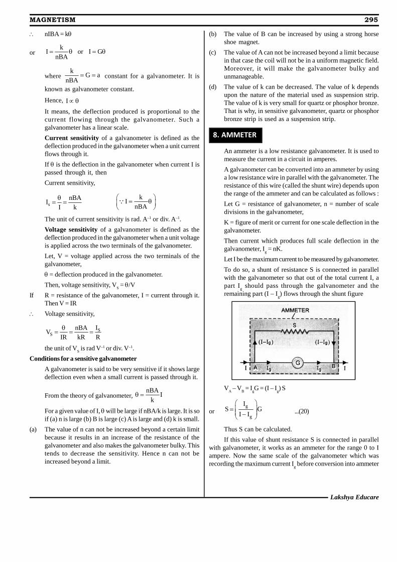
8. AMMETER
An ammeter is a low resistance galvanometer. It is used tomeasure the current in a circuit in amperes.
A galvanometer can be converted into an ammeter by usinga low resistance wire in parallel with the galvanometer. Theresistance of this wire (called the shunt wire) depends uponthe range of the ammeter and can be calculated as follows :
Let G = resistance of galvanometer, n = number of scaledivisions in the galvanometer,
K = figure of merit or current for one scale deflection in thegalvanometer.
Then current which produces full scale deflection in thegalvanometer, I
g = nK.
Let I be the maximum current to be measured by galvanometer.
To do so, a shunt of resistance S is connected in parallelwith the galvanometer so that out of the total current I, apart I
g should pass through the galvanometer and the
remaining part (I – Ig) flows through the shunt figure
VA – V
B = I
gG = (I – I
g) S
org
g
IS G
I I
...(20)
Thus S can be calculated.
If this value of shunt resistance S is connected in parallelwith galvanometer, it works as an ammeter for the range 0 to Iampere. Now the same scale of the galvanometer which wasrecording the maximum current I
g before conversion into ammeter
296 MAGNETISM
Mahesh Tutorials Science
will record the maximum current I, after conversion into ammeter.It means each division of the scale in ammeter will be showinghigher current than that of galvanometer.
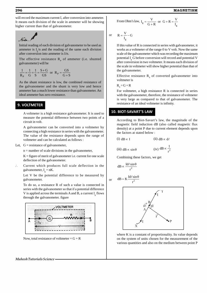
9. VOLTMETER
A voltmeter is a high resistance galvanometer. It is used tomeasure the potential difference between two points of acircuit in volt.
A galvanometer can be converted into a voltmeter byconnecting a high resistance in series with the galvanometer.The value of the resistance depends upon the range ofvoltmeter and can be calculated as follows :
Let, G = resistance of galvanometer,
n = number of scale divisions in the galvanometer,
K = figure of merit of galvanometer i.e. current for one scaledeflection of the galvanometer.
Current which produces full scale deflection in thegalvanometer, I
g = nK.
Let V be the potential difference to be measured bygalvanometer.
To do so, a resistance R of such a value is connected inseries with the galvanometer so that if a potential differenceV is applied across the terminals A and B, a current I
g flows
through the galvanometer. figure
Now, total resistance of voltmeter = G + R
From Ohm’s law, gg
V VI or G R
G R I
org
VR G
I
If this value of R is connected in series with galvanometer, itworks as a voltmeter of the range 0 to V volt. Now the samescale of the galvanometer which was recording the maximumpotential I
g G before conversion will record and potential V
after conversion in two voltmeter. It means each division ofthe scale in voltmeter will show higher potential than that ofthe galvanometer.
Effective resistance RS of converted galvanometer into
voltmeter is
RS = G + R
For voltmeter, a high resistance R is connected in serieswith the galvanometer, therefore, the resistance of voltmeteris very large as compared to that of galvanometer. Theresistance of an ideal voltmeter is infinity.
10. BIOT-SAVART’S LAW
According to Biot-Savart’s law, the magnitude of themagnetic field induction dB (also called magnetic fluxdensity) at a point P due to current element depends uponthe factors at stated below :
(i) dB I (ii) dB d
(iii) dB sin (iv) 2
1dB
r
Combining these factors, we get
2
Id sindB
r
or 2
Id sindB K
r
where K is a constant of proportionality. Its value dependson the system of units chosen for the measurement of thevarious quantities and also on the medium between point P
Initial reading of each division of galvanometer to be used asammeter is I
g/n and the reading of the same each division
after conversion into ammeter is I/n.
The effective resistance RP of ammeter (i.e. shunted
galvanometer) will be
PP
1 1 1 S G GSor R
R G S GS G S
As the shunt resistance is low, the combined resistance ofthe galvanometer and the shunt is very low and henceammeter has a much lower resistance than galvanometer. Anideal ammeter has zero resistance.
Lakshya Educare
MAGNETISM 297
and the current element. When there is free space betweencurrent element and point, then
In SI units, 0K4
and In cgs system K = 1
where 0 is absolute magnetic permeability of free space
and 7 1 1 7 10 4 10 Wb A m 4 10 TA m
( 1 T = 1 Wb m–2)
In SI units, 02
Id sindB
4 r
...(3)
In cgs system,2
Id sindB
r
In vector form, we may write
0 03 3
I d rI d rdB or dB
4 4r r
...(4)
Direction of dB
. From (4), the direction of dB
wouldobviously be the direction of the cross product vector,
d r . It is represented by the Right handed screw rule or
Right Hand Rule. Here dB
is perpendicular to the plane
containing d and r
and is directed inwards. If the point P
is to the left of the current element, dB
will be perpendicular
to the plane containing d and r
, directed outwards.
Some important features of Biot Savart’s law1. Biot Savart’s law is valid for a symmetrical current distribution.2. Biot Savart’s law is applicable only to very small length
conductor carrying current.
3. This law can not be easily verified experimentally as thecurrent carrying conductor of very small length can not beobtained practically.
4. This law is analogous to Coulomb’s law in electrostatics.
5. The direction of dB
is perpendicular to both Id and r
.
6. If = 0° i.e. the point P lies on the axis of the linear conductorcarrying current (or on the wire carrying current) then
02
Id sin 0dB 0
4 r
It means there is no magnetic field induction at any point onthe thin linear current carrying conductor.
7. If = 90° i.e. the point P lies at a perpendicular position w.r.t.current element, then
02
IddB
4 r
, which is maximum.
8. If = 0° or 180°, then dB = 0 i.e. minimum.
Similarities and Dis-similarities between the Biot-Savart’s lawfor the magnetic field and coulomb’s law for electrostatic fieldSimilarities
(i) Both the laws for fields are long range, since in both thelaws, the field at a point varies inversely as the square of thedistance from the source to point of observation.
(ii) Both the fields obey superposition principle.
(iii) The magnetic field is linear in the source Id , just as the
electric field is linear in its source, the electric charge q.
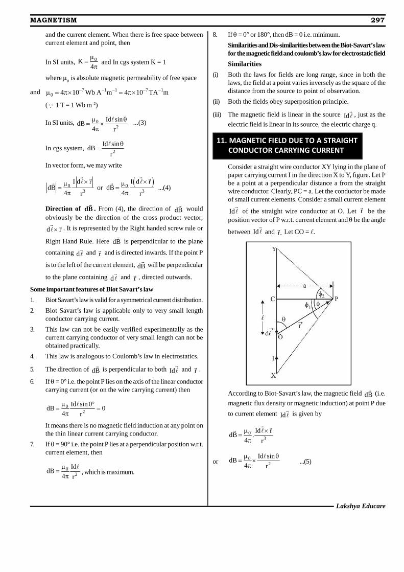
11. MAGNETIC FIELD DUE TO A STRAIGHT CONDUCTOR CARRYING CURRENT
Consider a straight wire conductor XY lying in the plane ofpaper carrying current I in the direction X to Y, figure. Let Pbe a point at a perpendicular distance a from the straightwire conductor. Clearly, PC = a. Let the conductor be madeof small current elements. Consider a small current element
Id of the straight wire conductor at O. Let r
be the
position vector of P w.r.t. current element and be the angle
between Id and r.
Let CO = .
According to Biot-Savart’s law, the magnetic field dB
(i.e.
magnetic flux density or magnetic induction) at point P due
to current element Id is given by
03
Id rdB .
4 r
or 02
Id sindB
4 r
...(5)
298 MAGNETISM
Mahesh Tutorials Science
In rt. angledPOC, + = 90° or = 90° – sin = sin (90° – ) = cos ...(6)
Also,a a
cos or rr cos
...(7)
And, tan or a tana
Differentiating it, we get
2d asec d ...(8)
Putting the values in (5) from (6), (7) and (8), we get
2
0 02
2
I a sec d cos IdB cos d
4 4 aa
cos
...(9)
The direction of dB
, according to right hand thumb rule,will be perpendicular to the plane of paper and directedinwards. As all the current elements of the conductor willalso produce magnetic field in the same direction, therefore,the total magnetic field at point P due to current through thewhole straight conductor XY can be obtained by integratingEq. (9) within the limits –
1 and +
2. Thus
2 2
20 0
11 1
I IB dB cos d sin
4 a 4 a
0 02 1 1 2
I Isin sin sin sin
4 a 4 a
...(10)
Special cases. (i) When the conductor XY is of infinite lengthand the point P lies near the centre of the conductor then
1 2 90
So, 0 0I 2IB sin90 sin90
4 a 4 a
...(11)
(ii) When the conductor XY is of infinite length but the point Plies near the end Y (or X) then
1 = 90° and
2 = 0°.
So, 0 0I IB sin90 sin 0
4 a 4 a
...(11 a)
Thus we note that the magnetic field due to an infinite longlinear conductor carrying current near its centre is twicethan that near one of its ends.
(iii) If length of conductor is finite, say L and point P lies onright bisector of conductor, then
1 2 and 2 2 22
L / 2 Lsin
4a La L / 2
Then, 0 0I 2IB sin sin sin
4 a 4 a
0
2 2
2I L
4 a 4a L
(iv) When point P lies on the wire conductor, then d and r
for
each element of the straight wire conductor are parallel.
Therefore, d r 0 . So the magnetic field induction at P = 0.
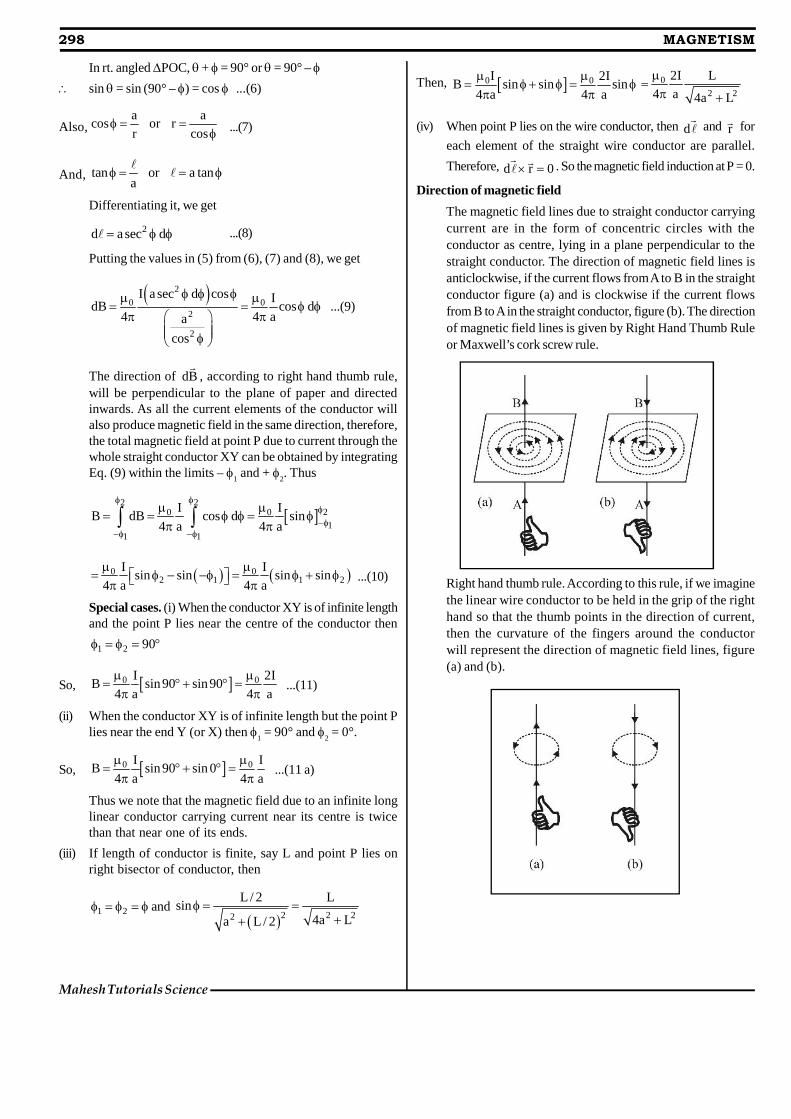
Direction of magnetic field
The magnetic field lines due to straight conductor carryingcurrent are in the form of concentric circles with theconductor as centre, lying in a plane perpendicular to thestraight conductor. The direction of magnetic field lines isanticlockwise, if the current flows from A to B in the straightconductor figure (a) and is clockwise if the current flowsfrom B to A in the straight conductor, figure (b). The directionof magnetic field lines is given by Right Hand Thumb Ruleor Maxwell’s cork screw rule.
Right hand thumb rule. According to this rule, if we imaginethe linear wire conductor to be held in the grip of the righthand so that the thumb points in the direction of current,then the curvature of the fingers around the conductorwill represent the direction of magnetic field lines, figure(a) and (b).
Lakshya Educare
MAGNETISM 299
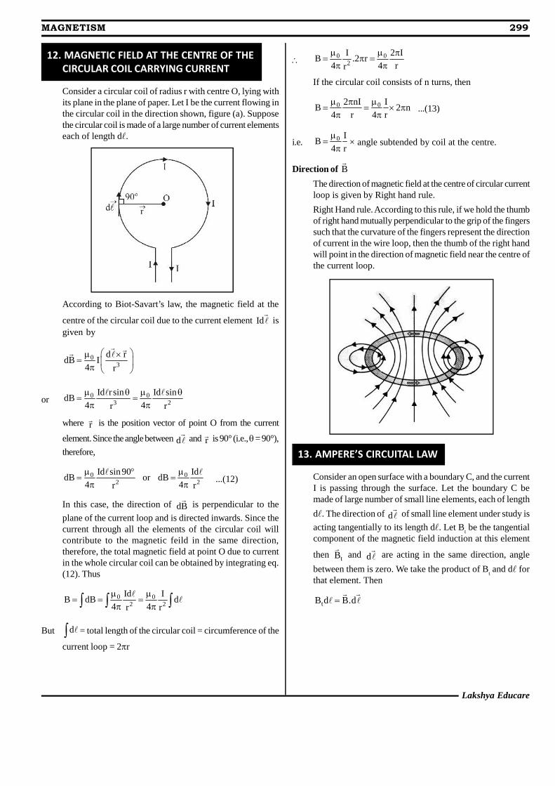
12. MAGNETIC FIELD AT THE CENTRE OF THECIRCULAR COIL CARRYING CURRENT
Consider a circular coil of radius r with centre O, lying withits plane in the plane of paper. Let I be the current flowing inthe circular coil in the direction shown, figure (a). Supposethe circular coil is made of a large number of current elementseach of length d.
According to Biot-Savart’s law, the magnetic field at the
centre of the circular coil due to the current element Id is
given by
03
d rdB I
4 r
or 0 03 2
Id r sin Id sindB
4 4r r
where r is the position vector of point O from the current
element. Since the angle between d and r
is 90° (i.e., = 90°),
therefore,
0 02 2
Id sin 90 IddB or dB
4 4r r
...(12)
In this case, the direction of dB
is perpendicular to the
plane of the current loop and is directed inwards. Since thecurrent through all the elements of the circular coil willcontribute to the magnetic feild in the same direction,therefore, the total magnetic field at point O due to currentin the whole circular coil can be obtained by integrating eq.(12). Thus
0 02 2
Id IB dB d
4 4r r
But d = total length of the circular coil = circumference of the
current loop = 2r
0 02
I 2 IB .2 r
4 4 rr
If the circular coil consists of n turns, then
0 02 nI IB 2 n
4 r 4 r
...(13)
i.e. 0 IB
4 r
× angle subtended by coil at the centre.
Direction of B
The direction of magnetic field at the centre of circular currentloop is given by Right hand rule.
Right Hand rule. According to this rule, if we hold the thumbof right hand mutually perpendicular to the grip of the fingerssuch that the curvature of the fingers represent the directionof current in the wire loop, then the thumb of the right handwill point in the direction of magnetic field near the centre ofthe current loop.
13. AMPERE’S CIRCUITAL LAW
Consider an open surface with a boundary C, and the currentI is passing through the surface. Let the boundary C bemade of large number of small line elements, each of length
d. The direction of d of small line element under study is
acting tangentially to its length d. Let Bt be the tangential
component of the magnetic field induction at this element
then tB
and d are acting in the same direction, angle
between them is zero. We take the product of Bt and d for
that element. Then
tB d B.d
300 MAGNETISM
Mahesh Tutorials Science
If length d is very small and products for all elements ofclosed boundary are added together, then sum tends to be
an integral around the closed path or loop (i.e., ) .
Therefore, of B.d over all elements on a closed path
B.d = Line integral of B
around the closed path or
loop whose boundary coincides with the closed path.According to Ampere’s circuital law,
0B.d I ...(19)
where I is the total current threading the closed path or loopa n d
0 is the absolute permeability of the space. Thus,
Ampere’s circuital law states that the line integral of magnetic
field induction B
around a closed path in vacuum is equal to
0 times the total current I threading the closed path.
The relation (19) involves a sign convention, for the senseof closed path to be traversed while taking the line integralof magnetic field (i.e., direction of integration) and currentthreading it, which is given by Right Hand Rule. Accordingto it, if curvature of the fingers is perpendicular to the thumbof right hand such that the curvature of the fingers representsthe sense, the boundary is traversed in the closed path or
loop for B.d , then the direction of thumb gives the sense
in which the current I is regarded as positive.
According to sign convention, for the closed path as shownin figure, I
1 is positive and I
2 is negative. Then, according to
Ampere’s circuital law
0 1 2 0 eB.d I I I
where Ie is the total current enclosed by the loop or closed path.
The relation (19) is independent of the size and shape of theclosed path or loop enclosing the current.
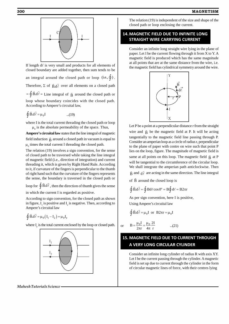
14. MAGNETIC FIELD DUE TO INFINITE LONGSTRAIGHT WIRE CARRYING CURRENT
Consider an infinite long straight wire lying in the plane ofpaper. Let I be the current flowing through it from X to Y. Amagnetic field is produced which has the same magnitudeat all points that are at the same distance from the wire, i.e.the magnetic field has cylindrical symmetry around the wire.
Let P be a point at a perpendicular distance r from the straight
wire and B
be the magnetic field at P. It will be acting
tangentially to the magnetic field line passing through P.Consider an amperian loop as a circle of radius r, perpendicularto the plane of paper with centre on wire such that point Plies on the loop, figure. The magnitude of magnetic field is
same at all points on this loop. The magnetic field B
at P
will be tangential to the circumference of the circular loop.We shall integrate the amperian path anticlockwise. Then
B
and d are acting in the same direction. The line integral
of B
around the closed loop is
B.d Bd cos0 B d B2 r
As per sign convention, here I is positive,
Using Ampere’s circuital law
0 0B.d I or B2 r I
or 0 0I 2IB
2 r 4 r
...(21)
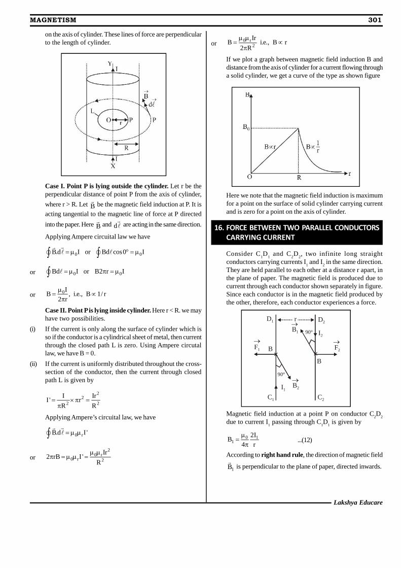
15. MAGNETIC FIELD DUE TO CURRENT THROUGHA VERY LONG CIRCULAR CYLINDER
Consider an infinite long cylinder of radius R with axis XY.Let I be the current passing through the cylinder. A magneticfield is set up due to current through the cylinder in the formof circular magnetic lines of force, with their centres lying
Lakshya Educare
MAGNETISM 301
on the axis of cylinder. These lines of force are perpendicularto the length of cylinder.
Case I. Point P is lying outside the cylinder. Let r be theperpendicular distance of point P from the axis of cylinder,
where r > R. Let B
be the magnetic field induction at P. It is
acting tangential to the magnetic line of force at P directed
into the paper. Here B
and d are acting in the same direction.
Applying Ampere circuital law we have
0 0B.d I or Bd cos0 I
or 0 0Bd I or B2 r I
or 0IB , i.e., B 1/ r
2 r
Case II. Point P is lying inside cylinder. Here r < R. we mayhave two possibilities.
(i) If the current is only along the surface of cylinder which isso if the conductor is a cylindrical sheet of metal, then currentthrough the closed path L is zero. Using Ampere circutallaw, we have B = 0.
(ii) If the current is uniformly distributed throughout the cross-section of the conductor, then the current through closedpath L is given by
22
2 2
I IrI ' r
R R
Applying Ampere’s circuital law, we have
0 rB.d I '
or2
0 r0 r 2
Ir2 rB I '
R
or 0 r2
IrB i.e., B r
2 R
If we plot a graph between magnetic field induction B anddistance from the axis of cylinder for a current flowing througha solid cylinder, we get a curve of the type as shown figure
Here we note that the magnetic field induction is maximumfor a point on the surface of solid cylinder carrying currentand is zero for a point on the axis of cylinder.
16. FORCE BETWEEN TWO PARALLEL CONDUCTORSCARRYING CURRENT
Consider C1D
1 and C
2D
2, two infinite long straight
conductors carrying currents I1 and I
2 in the same direction.
They are held parallel to each other at a distance r apart, inthe plane of paper. The magnetic field is produced due tocurrent through each conductor shown separately in figure.Since each conductor is in the magnetic field produced bythe other, therefore, each conductor experiences a force.
F2F1
I1
I2
C2C1
D1 D2
B1
B2
90°
90°
r
B
B× ×
Magnetic field induction at a point P on conductor C2D
2
due to current I1 passing through C
1D
1 is given by
0 11
2IB
4 r
...(12)
According to right hand rule, the direction of magnetic field
1B
is perpendicular to the plane of paper, directed inwards.
302 MAGNETISM
Mahesh Tutorials Science
As the current carrying conductor C2D
2 lies in the magnetic
field 1B
(produced by the current through C1D
1), therefore,
the unit length of C2D
2 will experience a force given by
F2 = B
1I
2 × 1 = B
1I
2
Putting the value of B1, we have
0 1 22
2I IF .
4 r
...(13)
It means the two linear parallel conductors carryingcurrents in the same direction attract each other.
Thus one ampere is that much current which when flowingthrough each of the two parallel uniform long linearconductors placed in free space at a distance of one metrefrom each other will attract or repel each other with a forceof 2 × 10⁻⁷ N per metre of their length.
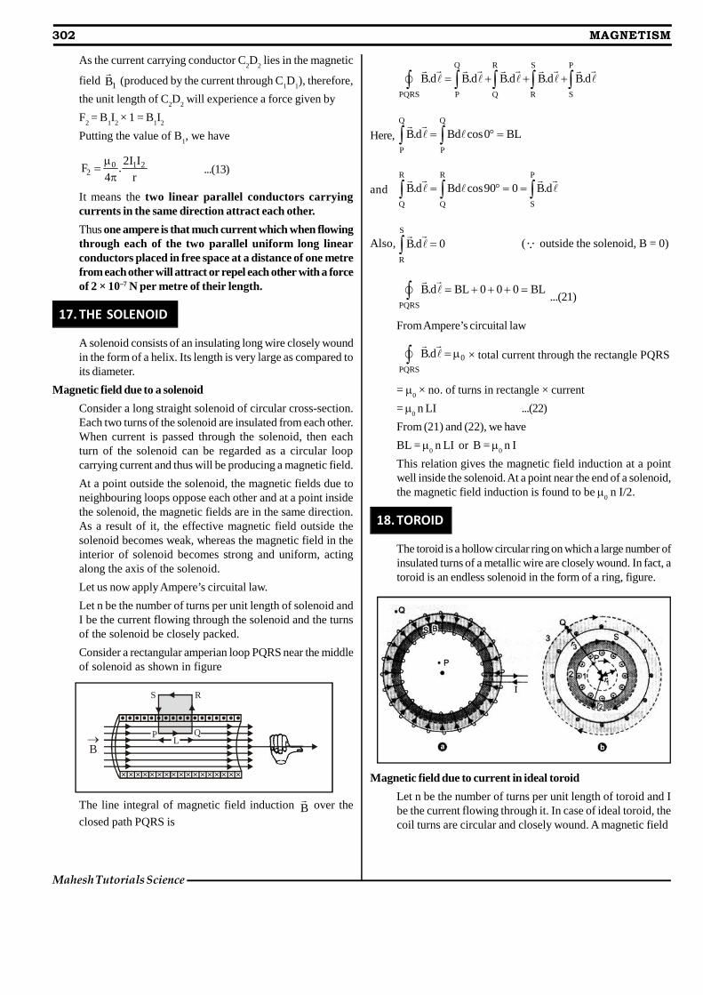
17. THE SOLENOID
A solenoid consists of an insulating long wire closely woundin the form of a helix. Its length is very large as compared toits diameter.
Magnetic field due to a solenoid
Consider a long straight solenoid of circular cross-section.Each two turns of the solenoid are insulated from each other.When current is passed through the solenoid, then eachturn of the solenoid can be regarded as a circular loopcarrying current and thus will be producing a magnetic field.
At a point outside the solenoid, the magnetic fields due toneighbouring loops oppose each other and at a point insidethe solenoid, the magnetic fields are in the same direction.As a result of it, the effective magnetic field outside thesolenoid becomes weak, whereas the magnetic field in theinterior of solenoid becomes strong and uniform, actingalong the axis of the solenoid.
Let us now apply Ampere’s circuital law.Let n be the number of turns per unit length of solenoid andI be the current flowing through the solenoid and the turnsof the solenoid be closely packed.
Consider a rectangular amperian loop PQRS near the middleof solenoid as shown in figure
× × × × × × × × × × × × × × × × ×
B
S R
LP Q
The line integral of magnetic field induction B
over the
closed path PQRS is
Q R S P
PQRS P Q R S
B.d B.d B.d B.d B.d
Here,Q Q
P P
B.d Bd cos0 BL
andR R P
Q Q S
B.d Bd cos90 0 B.d
Also,S
R
B.d 0 ( outside the solenoid, B = 0)
PQRS
B.d BL 0 0 0 BL ...(21)
From Ampere’s circuital law
0
PQRS
B.d × total current through the rectangle PQRS
= 0 × no. of turns in rectangle × current
= 0 n LI ...(22)
From (21) and (22), we have
BL = 0 n LI or B =
0 n I
This relation gives the magnetic field induction at a pointwell inside the solenoid. At a point near the end of a solenoid,the magnetic field induction is found to be
0 n I/2.
18. TOROID
The toroid is a hollow circular ring on which a large number ofinsulated turns of a metallic wire are closely wound. In fact, atoroid is an endless solenoid in the form of a ring, figure.
Magnetic field due to current in ideal toroid
Let n be the number of turns per unit length of toroid and Ibe the current flowing through it. In case of ideal toroid, thecoil turns are circular and closely wound. A magnetic field
Lakshya Educare
MAGNETISM 303
of constant magnitude is set up inside the turns of toroid inthe form of concentric circular magnetic field lines. Thedirection of the magnetic field at a point is given by thetangent to the magnetic field line at that point. We drawthree circular amperian loops, 1, 2 and 3 of radii r
1, r
2 and r
3 to
be traversed in clockwise direction as shown by dashedcircles in figure, so that the points P, S and Q may lie onthem. The circular area bounded by loops 2 and 3, both cutthe toroid. Each turn of current carrying wire is cut once bythe loop 2 and twice by the loop 3. Let B
1 be the magnitude
of magnetic field along loop 1. Line integral of magneticfield B
1 along the loop 1 is
1 1 1 1
loop1 loop1
B .d B d cos0 B 2 r ...(i)
Loop 1 encloses no current.
According to Ampere’s circuital law
1 0
loop1
B .d current enclosed by loop1 =
0 × 0 = 0
or B12 r
1 = 0 or B
1 = 0
Let B3 be the magnitude of magnetic field along the loop 3.
The line integral of magnetic field B3 along the loop 3 is
3 3 3 3
loop 3 loop 3
B .d B d cos0 B 2 r
From the sectional cut as shown in figure, we note that thecurrent coming out of the plane of paper is cancelled exactlyby the current going into it. Therefore, the total currentenclosed by loop 3 is zero.
According to Ampere’s circuital law
3
loop 3
B .d
0 × total current through loop 3
or 3 3 0 3B 2 r 0 0 or B 0
Let B the magnitude of magnetic field along the loop 2. Lineintegral of magnetic field along the loop 2 is
2
loop 2
B.d B2 r
Current enclosed by the loop 2 = number of turns × currentin each turn = 2 r
2 n × I
According to Ampere’s circuital law
0
loop 2
B.d total current
or 2 0 2 0B2 r 2 r nI or B nI
19. MAGNETISM & MATTER
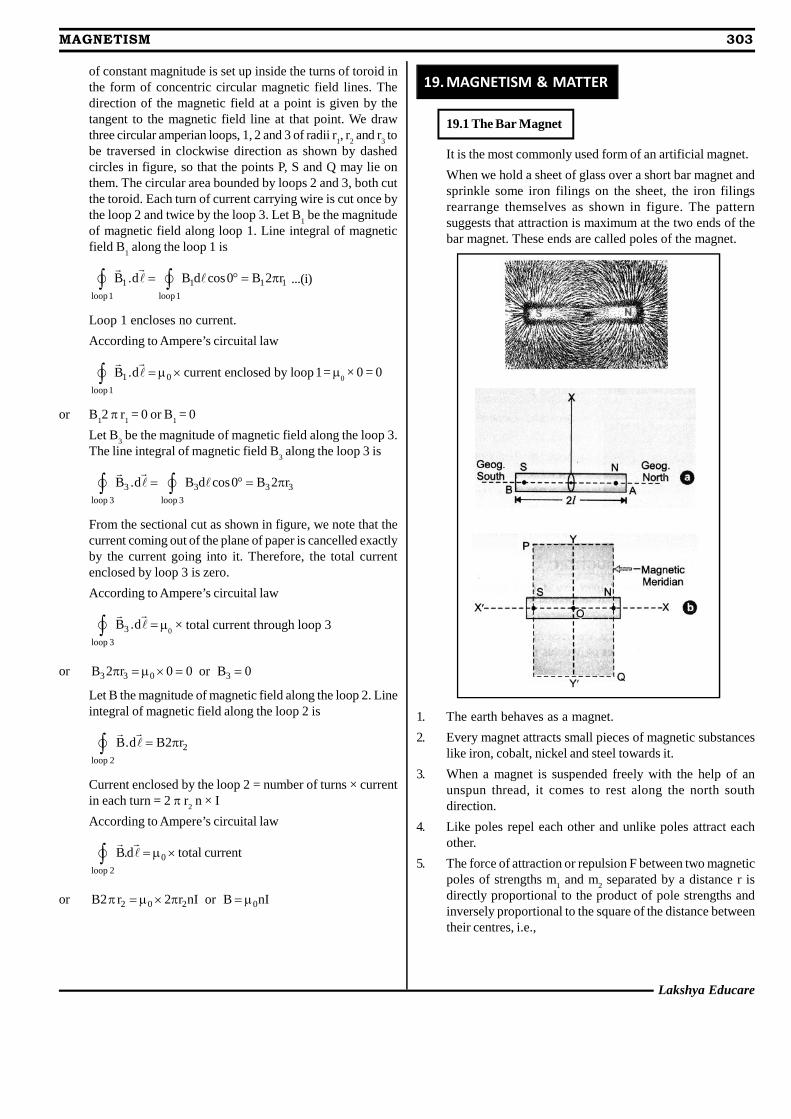
19.1 The Bar Magnet
It is the most commonly used form of an artificial magnet.
When we hold a sheet of glass over a short bar magnet andsprinkle some iron filings on the sheet, the iron filingsrearrange themselves as shown in figure. The patternsuggests that attraction is maximum at the two ends of thebar magnet. These ends are called poles of the magnet.
1. The earth behaves as a magnet.
2. Every magnet attracts small pieces of magnetic substanceslike iron, cobalt, nickel and steel towards it.
3. When a magnet is suspended freely with the help of anunspun thread, it comes to rest along the north southdirection.
4. Like poles repel each other and unlike poles attract eachother.
5. The force of attraction or repulsion F between two magneticpoles of strengths m
1 and m
2 separated by a distance r is
directly proportional to the product of pole strengths andinversely proportional to the square of the distance betweentheir centres, i.e.,
304 MAGNETISM
Mahesh Tutorials Science
1 2 1 22 2
m m m mF or F K
r r , where K is magnetic force
constant.
In SI units, 7 1 10K 10 Wb A m4
where 0 is absolute magnetic permeability of free space
(air/vacuum).
0 1 2
2
m mF
4 r
...(1)
This is called Coulomb’s law of magnetic force. However, incgs system, the value of K = 1.
This corresponds to Coulomb’s law in electrostatics.
SI Unit of magnetic pole strength
Suppose m1 = m
2 = m (say),
r = 1 m and F = 10–7 N
From equation (1),
7 7 22
m m10 10 or m 1
1 or m = +1 ampere-metre
(Am). Therefore, strength of a magnetic pole is said to beone ampere-metre, if it repels an equal and similar pole, whenplaced in vacuum (or air) at a distance of one metre from it,with a force of 10–7 N.
6. The magnetic poles always exist in pairs. The poles of amagnet can never be separated i.e. magnetic monopoles donot exist.
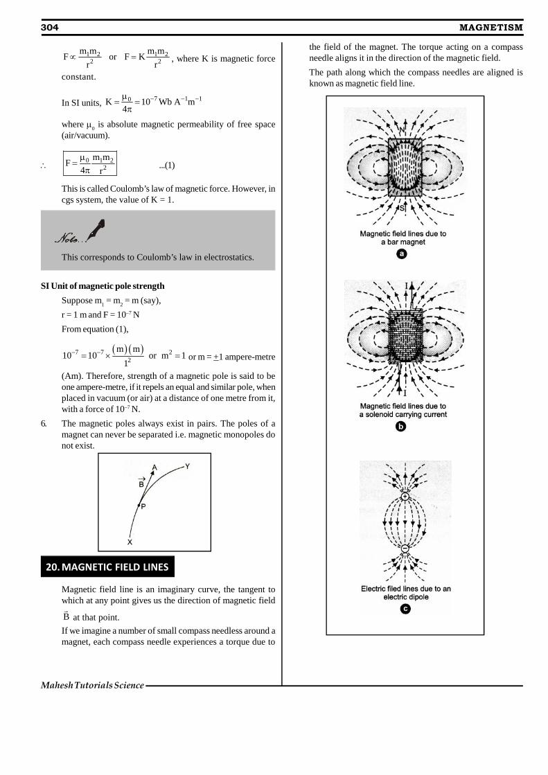
20. MAGNETIC FIELD LINES
Magnetic field line is an imaginary curve, the tangent towhich at any point gives us the direction of magnetic field
B
at that point.
If we imagine a number of small compass needless around amagnet, each compass needle experiences a torque due to
the field of the magnet. The torque acting on a compassneedle aligns it in the direction of the magnetic field.
The path along which the compass needles are aligned isknown as magnetic field line.
Lakshya Educare
MAGNETISM 305
Properteis of magnetic field lines
1. The magnetic field lines of a magnet (or of a solenoidcarrying current) form closed continuous loops.
2. Outside the body of the magnet, the direction of magneticfield lines is from north pole to south pole.
3. At any given point, tangent to the magnetic field line
represents the direction of net magnetic field ( B
) at thatpoint.
4. The magnitude of magnetic field at any point is representedby the number of magnetic field lines passing normallythrough unit area around that point. Therefore, crowdedlines represent a strong magnetic field and lines which arenot so crowded represent a weak magnetic field.
5. No two magnetic field lines can intersect each other.
21. MAGNETIC DIPOLE
A magnetic dipole consists of two unlike poles of equalstrength and separated by a small distance.
For example, a bar magnet, a compass needle etc. aremagnetic dipoles. We shall show that a current loop behavesas a magnetic dipole. An atom of a magnetic material behavesas a dipole due to electrons revolving around the nucleus.
The two poles of a magnetic dipole (or a magnet), callednorth pole and south pole are always of equal strength, andof opposite nature. Further such two magnetic poles existalways in pairs and cannot be separated from each other.
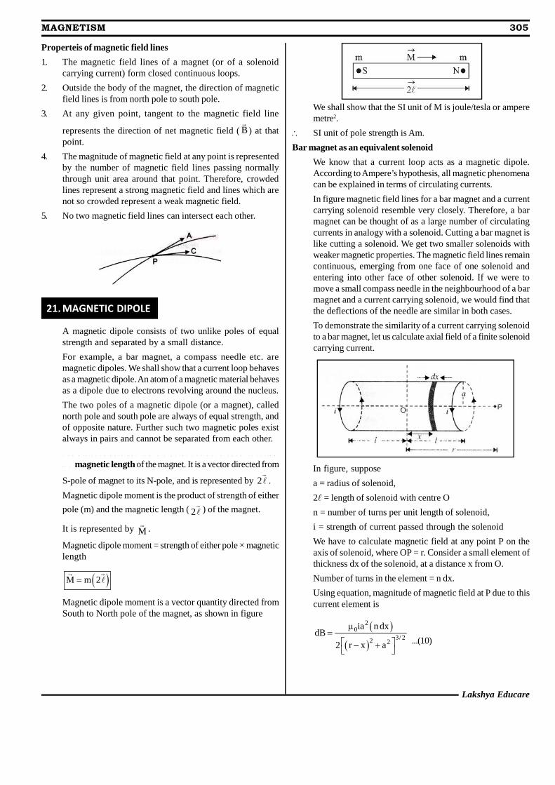
T h e d i s t a n c e b e t w e e n t h e t w o p o l e s o f a b a r m a g n e t i s c a l l e d
t h e magnetic length of the magnet. It is a vector directed from
S-pole of magnet to its N-pole, and is represented by 2 .
Magnetic dipole moment is the product of strength of either
pole (m) and the magnetic length ( 2 ) of the magnet.
It is represented by M
.
Magnetic dipole moment = strength of either pole × magneticlength
M m 2
Magnetic dipole moment is a vector quantity directed fromSouth to North pole of the magnet, as shown in figure
We shall show that the SI unit of M is joule/tesla or amperemetre2.
SI unit of pole strength is Am.
Bar magnet as an equivalent solenoid
We know that a current loop acts as a magnetic dipole.According to Ampere’s hypothesis, all magnetic phenomenacan be explained in terms of circulating currents.
In figure magnetic field lines for a bar magnet and a currentcarrying solenoid resemble very closely. Therefore, a barmagnet can be thought of as a large number of circulatingcurrents in analogy with a solenoid. Cutting a bar magnet islike cutting a solenoid. We get two smaller solenoids withweaker magnetic properties. The magnetic field lines remaincontinuous, emerging from one face of one solenoid andentering into other face of other solenoid. If we were tomove a small compass needle in the neighbourhood of a barmagnet and a current carrying solenoid, we would find thatthe deflections of the needle are similar in both cases.
To demonstrate the similarity of a current carrying solenoidto a bar magnet, let us calculate axial field of a finite solenoidcarrying current.
In figure, suppose
a = radius of solenoid,
2 = length of solenoid with centre O
n = number of turns per unit length of solenoid,
i = strength of current passed through the solenoid
We have to calculate magnetic field at any point P on theaxis of solenoid, where OP = r. Consider a small element ofthickness dx of the solenoid, at a distance x from O.
Number of turns in the element = n dx.
Using equation, magnitude of magnetic field at P due to thiscurrent element is
20
3/ 22 2
ia n dxdB
2 r x a
...(10)
306 MAGNETISM
Mahesh Tutorials Science
If P lies at a very large distance from O, i.e., r >> a and r >> x,then [(r – x)2 + a2]3/2 r3
20
3
ia ndxdB
2r
...(11)
As range of variation of x is from x = – to x = +, thereforethe magnitude of total magnetic field at P due to currentcarrying solenoid
x2 2
x0 03 3 x
x
nia niaB dx x
2r 2r
220 0
3 3
2n 2 i ani aB 2
2 4r r
...(12)
If M is magnetic moment of the solenoid, then
M = total no. of turns × current × area of cross section
M = n (2) × i × (a2)
0
3
2MB
4 r
...(13)
This is the expression for magnetic field on the axial line ofa short bar magnet.
Thus, the axial field of a finite solenoid carrying current issame as that of a bar magnet. Hence, for all practical purposes,a finite solenoid carrying current is equivalent to a bar magnet.
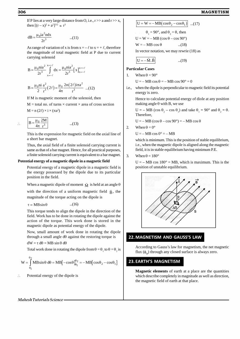
Potential energy of a magnetic dipole in a magnetic field
Potential energy of a magnetic dipole in a magnetic field isthe energy possessed by the dipole due to its particularposition in the field.
When a magnetic dipole of moment M
is held at an angle
with the direction of a uniform magnetic field B
, the
magnitude of the torque acting on the dipole is
MBsin ...(16)
This torque tends to align the dipole in the direction of thefield. Work has to be done in rotating the dipole against theaction of the torque. This work done is stored in themagnetic dipole as potential energy of the dipole.
Now, small amount of work done in rotating the dipolethrough a small angle d against the restoring torque is
dW = d= MB sin d
Total work done in rotating the dipole from= 1 to =
2 is
2
22 11
1
W MBsin d MB cos MB cos cos
Potential energy of the dipole is
2 1U W MB cos cos ...(17)
W h e n 1 = 90°, and
2 = , then
U = W = – MB (cos – cos 90°)W = – MB cos ...(18)
In vector notation, we may rewrie (18) as
U M.B
...(19)
Particular Cases
1. When = 90°
U = – MB cos = – MB cos 90° = 0i.e., when the dipole is perpendicular to magnetic field its potential
energy is zero.
Hence to calculate potential energy of diole at any positionmaking angle with B, we use
U = – MB (cos 2 – cos
1) and take
1 = 90° and
2 = .
Therefore,
U = – MB (cos – cos 90°) = – MB cos 2. When = 0°
U = – MB cos 0° = – MBwhich is minimum. This is the position of stable equilibrium,i.e., when the magnetic dipole is aligned along the magneticfield, it is in stable equilibrium having minimum P.E.
3. When = 180°
U = – MB cos 180° = MB, which is maximum. This is theposition of unstable equilibrium.
22. MAGNETISM AND GAUSS’S LAW
According to Gauss’s law for magnetism, the net magneticflux (
B) through any closed surface is always zero.
23. EARTH’S MAGNETISM
Magnetic elements of earth at a place are the quantitieswhich describe completely in magnitude as well as direction,the magnetic field of earth at that place.
Lakshya Educare
MAGNETISM 307
23.1 Magnetic declination
Magnetic declination at a place is the angle betweenmagnetic meridian and geographic meridian at that place.
Retain in Memory
1. The earth’s magnetic poles are not at directly opposite positionson globe. Current magnetic south is farther from geographicsouth than magnetic north is from geographic north.
2. Infact, the magnetic field of earth varies with position andalso with time. For example, in a span of 240 years from 1580to 1820 A.D., the magnetic declination at London has beenfound to change by 3.5° – suggesting that magnetic polesof earth change their position with time.
3. The magnetic declination in India is rather small. At Delhi,declination is only 0° 41’ East and at Mumbai, the declinationis 0° 58’ West. Thus at both these places, the direction ofgeographic north is given quite accurately by the compassneedle (within 1° of the actual direction).
23.2 Magnetic Dip or Magnetic Inclination
Magnetic dip or magnetic inclination at a place is defined asthe angle which the direction of total strength of earth’smagnetic field makes with a horizontal line in magnetic meridian.
23.3 Horizontal Component
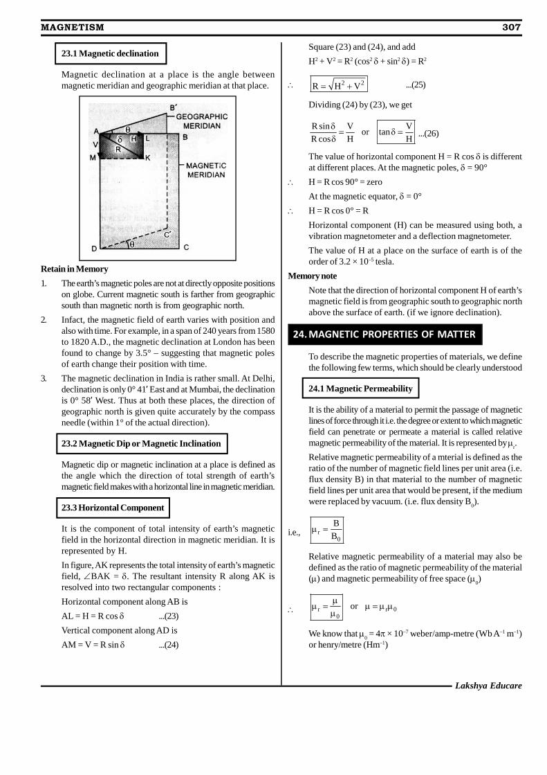
It is the component of total intensity of earth’s magneticfield in the horizontal direction in magnetic meridian. It isrepresented by H.
In figure, AK represents the total intensity of earth’s magneticfield, BAK = . The resultant intensity R along AK isresolved into two rectangular components :
Horizontal component along AB is
AL = H = R cos ...(23)
Vertical component along AD is
AM = V = R sin ...(24)
Square (23) and (24), and add
H2 + V2 = R2 (cos2 + sin2 ) = R2
2 2R H V ...(25)
Dividing (24) by (23), we get
R sin V Vor tan
R cos H H
...(26)
The value of horizontal component H = R cos is differentat different places. At the magnetic poles, = 90°
H = R cos 90° = zero
At the magnetic equator, = 0°
H = R cos 0° = R
Horizontal component (H) can be measured using both, avibration magnetometer and a deflection magnetometer.
The value of H at a place on the surface of earth is of theorder of 3.2 × 10⁻⁵ tesla.
Memory note
Note that the direction of horizontal component H of earth’smagnetic field is from geographic south to geographic northabove the surface of earth. (if we ignore declination).
24. MAGNETIC PROPERTIES OF MATTER
To describe the magnetic properties of materials, we definethe following few terms, which should be clearly understood
24.1 Magnetic Permeability
It is the ability of a material to permit the passage of magneticlines of force through it i.e. the degree or extent to which magneticfield can penetrate or permeate a material is called relativemagnetic permeability of the material. It is represented by
r.
Relative magnetic permeability of a mterial is defined as theratio of the number of magnetic field lines per unit area (i.e.flux density B) in that material to the number of magneticfield lines per unit area that would be present, if the mediumwere replaced by vacuum. (i.e. flux density B
0).
i.e., r0
B
B
Relative magnetic permeability of a material may also bedefined as the ratio of magnetic permeability of the material() and magnetic permeability of free space (
0)
r r 00
or
We know that 0 = 4 × 10⁻⁷ weber/amp-metre (Wb A–1 m–1)
or henry/metre (Hm–1)
308 MAGNETISM
Mahesh Tutorials Science
SI units of permeability () are
Hm–1 = Wb A–1 m–1 = (T m2) A–1 m–1 = T m A–1
24.2 Magnetic Intensity ( H
)
The degree to which a magnetic field can magnetise a materialis represented in terms of magnetising force or magnetise
intensity ( H
).
24.3 Magnetisation or Intensity of Magnetisation ‘I’
It represents the extent to which a specimen is magnetised,when placed in a magnetising field. Quantitatively,
The magnetisation of a magnetic material is defined as themagnetic moment per unit volume of the material.
Magnetic moment mM
volume V
There are SI unit of I, which are the same as SI units of H.
Magnetic susceptibility ( m ) of a magnetic material is
defined as the ratio of the intensity of magnetisation (I)induced in the material to the magnetising force (H) applied
on it. Magnetic susceptibility is represented by m .
Thus mI
H
Relation between magnetic permeability and magneticsusceptibility
When a magnetic material is placed in a magnetising field ofmagnetising intensity H, the material gets magnetised. Thetotal magnetic induction B in the material is the sum of themagnetic induction B
0 in vacuum produced by the magnetic
intensity and magnetic induction Bm, due to magnetisation
of the material. Therefore,
B = B0 + B
m
But B0 =
0 H and B
m = m
0 I, where I is the intensity of
magnetisation induced in the magnetic material. Therefore,from above
0 0 0B H I H I ,
i.e., 0B H I
Now as m mI
I HH
From above, 0 m 0 mB H H H 1
But B =H
0 m m0
H H 1 or 1
or r m1
This is the relation between relative magnetic permeabilityand magnetic susceptibility of the material.
25. CLASSIFICATION OF MAGNETIC MATERIALS
There is a large variety of elements and compounds on earth.Some new elements, alloys and compounds have beensynthesized in the laboratory. Faraday classified thesesubstances on the basis of their magnetic properties, intothe following three categories :
(i) Diamagnetic substances,
(ii) Paramagnetic substances, and
(iii) Ferromagnetic substances
Their main characteristics are discussed below :
25.1 Diamagnetic Substances
The diamagnetic substances are those in which theindividual atoms/molecules/ions do not possess any netmagnetic moment on their own. When such substances areplaced in an external magnetising field, they get feeblymagnetised in a direction opposite to the magnetising field.
when placed in a non-uniform magnetic field, thesesubstances have a tendency to move from stronger parts ofthe field to the weaker parts.
When a specimen of a diamagnetic material is placed in amagnetising field, the magnetic field lines prefer not to passthrough the specimen.
Relative magnetic permeability of diamagnetic substancesis always less than unity.
From the relation r m r m1 , as 1, is negative.
Hence susceptibility of diamagnetic substances has a smallnegative value.
A superconductor repels a magnet and in turn, is repelledby the magnet.
The phenomenon of perfect diamagnetism insuperconductors is called Meissner effect. Superconductingmagnets have been used for running magnetically leviatedsuperfast trains.
25.2 Paramagnetic substances
Paramagnetic substacnes are those in which each individualatom/molecule/ion has a net non zero magnetic moment ofits own. When such substances are placed in an external
Lakshya Educare
MAGNETISM 309
magnetic field, they get feebly magnetised in the directionof the magnetising field.
When placed in a non-uniform magnetic field, they tend tomove from weaker parts of the field to the stronger parts.
When a specimen of a paramagnetic substance is placed ina magnetising field, the magnetic field lines prefer to passthrough the specimen rather than through air.
From the SI relation, r m r1 , as 1 , therefore, mmust be positive. Hence, susceptibility of paramagneticsubstances is positive, though small.
Susceptibility of paramagnetic substances varies inversely
as the temperature of the substance i.e. m1
T i.e. they
lose their magnetic character with rise in temperature.
25.3 Ferromagnetic substances
Ferromagnetic substances are those in which each individualatom/molecule/ion has a non zero magnetic moment, as in aparamagnetic substance.
When such substances are placed in an external magnetisingfield, they get strongly magnetised in the direction of the field.
The ferromagnetic materials show all the properties ofparamagnetic substances, but to a much greater degree. Forexample,
(i) They are strongly magnetised in the direction of externalfield in which they are placed.
(ii) Relative magnetic permeability of ferromagnetic materials isvery large ( 103 to 105)
(iii) The susceptibility of ferromagnetic materials is also very
large. m r 1
That is why they can be magnetised easily and strongly.
(iv) With rise in temperature, susceptibility of ferromagneticsdecreases. At a certain temperature, ferromagnetics changeover to paramagnetics. This transition temperature is calledcurie temperature. For example, curie temperature of iron isabout 1000 K.
25.4 Curie Law in Magnetism
According to Curie law,
Intensity of magnetisation (I) of a magnetic material is (i)directly proportional to magnetic induction (B), and (ii)
inversely proportional to the temperature (T) of the material.
i.e.,1
I B, and IT
Combining these factors, we getB
IT
As B H , magnetising intensity
H I 1
I orT H T
But mI
H
m m1 C
orT T
where C is a constant of proportionality and is called Curieconstant.
26. HYSTERISIS CURVE
The hysterisis curve represents the relation between
magnetic induction B
(or intensity of magnetization I
) of
a ferromagnetic material with magnetiziing force or magnetic
intensity H
. The shape of the hysterisis curve is shown in
figure. It represents the behaviour of the material as it istaken through a cycle of magnetization.
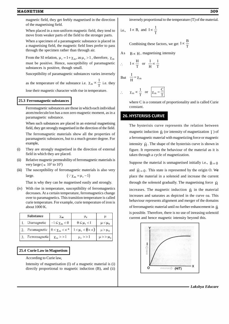
Suppose the material is unmagnetised initially i.e., B 0
and H 0
. This state is represented by the origin O. Wee
place the material in a solenoid and increase the current
through the solenoid gradually. The magnetising force H
increases. The magnetic induction B
in the material
increases and saturates as depicted in the curve oa. Thisbehaviour represents alignment and merger of the domains
of ferromagnetic material until no further enhancement in B
is possible. Therefore, there is no use of inreasing solenoidcurrent and hence magnetic intensity beyond this.

310 MAGNETISM
Mahesh Tutorials Science
Next, we decrease the solenoid current and hence magnetic
intensity H
till it reduces to zero. The curve follows the
path ab showing that when H 0
, B 0
. Thus, some
magnetism is left in the specimen.
The value of magnetic induction B
left in the specimen
when the magnetising force is reduced to zero is calledRetentivity or Remanence or Residual magnetism of thematerial.
It shows that the domains are not completely randomisedeven when the magnetising force is removed. Next, thecurrent in the solenoid is reversed and increased slowly.Certain domains are flipped until the net magnetic induction
B
inside is reduced to zero. This is represented by the
curve bc. It means to reduce the residual magnetism orretentivity to zero, we have to apply a magnetising force =OC in opposite direction. This value of magnetising force iscalled coercivity of the material.
As the reverse current in solenoid is increased in magnitude,we once again obtain saturation in the reverse direction atd. The variation is represented by the curve cd. Next, thesolenoid current is reduced (curve de), reversed andincreased (curve ea). The cycle repeats itself. From figure,we find that saturated magnetic induction B
S is of the order
of 1.5 T and coercivity is of the order of –90 Am–1.
From the above discussion, it is clear that when a specimenof a magnetic material is taken through a cycle ofmagnetisation, the intensity of magnetisation (I) andmagnetic induction (B) lag behind the magnetising force(H). Thus, even if the magnetising force H is made zero, thevalues of I and B do not reduce to zero i.e., the specimentends to retain the magnetic properties.
This phenomenon of lagging of I or B behind H when aspecimen of a magnetic material is subjected to a cycle ofmagnetisation is called hysteresis.
For example, hysteresis loop for soft iron is narrow andlarge, whereas the hysteresis loop for steel is wide and short,figure
The hysterisis loops of soft iron and steel reveal that
(i) The retentivity of soft iron is greater than the retentivity ofsteel,
(ii) Soft iron is more strongly magnetised than steel,
(iii) Coercivity of soft iron is less than coercivity of steel. Itmeans soft iron loses its magnetism more rapidly than steeldoes.
(iv) As area of I-H loop for soft iron is smaller than the area ofI-H loop for steel, therefore, hysterisis loss in case of softiron is smaller than the hysterisis loss in case of steel.
(a) Permanent Magnets
Permanent magnets are the materials which retain at roomtemperature, their ferromagnetic properties for a long time.The material chosen should have
(i) high retentivity so that the magnet is strong,
(ii) high coercivity so that the magnetisation is not erased bystray magnetic fields, temperature changes or mechanicaldamage due to rough handling etc.
(iii) high permeability so that it can be magnetised easily.
Steel is preferred for making permanent magnets.
(b) Electromagnets
The core of electromagnets are made of ferromagneticmaterials, which have high permeability and low retentivity.Soft iron is a suitable material for this purpose. When a softiron rod is placed in a solenoid and current is passed throughthe solenoid, magnetism of the solenoid is increased by athousand fold. When the solenoid current is switched off,the magnetism is removed instantly as retentivity of softiron is very low. Electromagnets are used in electric bells,loudspeakers and telephone diaphragms. Giantelectromagnets are used in cranes to lift machinery etc.
Lakshya Educare
MAGNETISM 311
312 MAGNETISM
Mahesh Tutorials Science
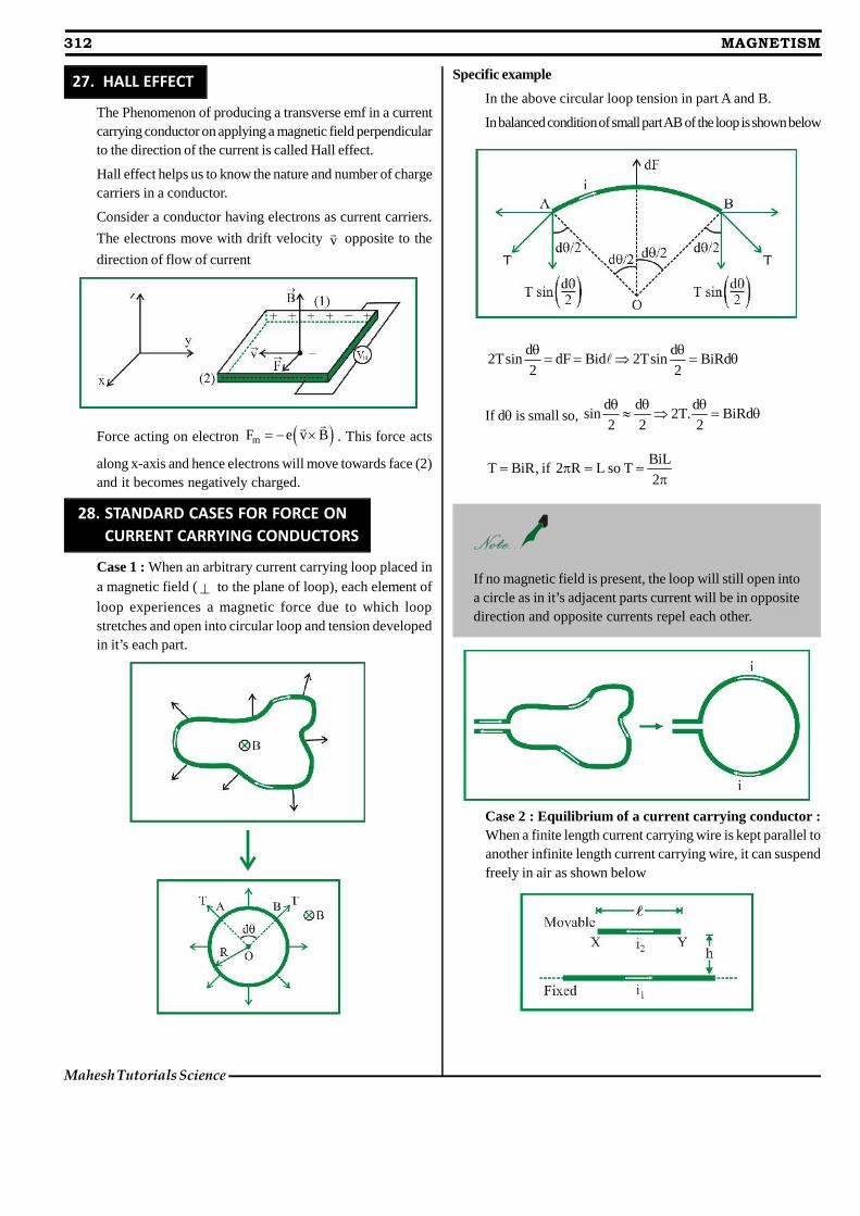
27. HALL EFFECT
The Phenomenon of producing a transverse emf in a currentcarrying conductor on applying a magnetic field perpendicularto the direction of the current is called Hall effect.
Hall effect helps us to know the nature and number of chargecarriers in a conductor.
Consider a conductor having electrons as current carriers.
The electrons move with drift velocity v opposite to the
direction of flow of current
Force acting on electron mF e v B
. This force acts
along x-axis and hence electrons will move towards face (2)and it becomes negatively charged.
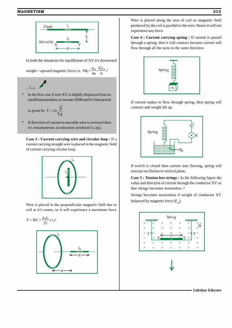
28. STANDARD CASES FOR FORCE ON CURRENT CARRYING CONDUCTORS
Case 1 : When an arbitrary current carrying loop placed ina magnetic field ( to the plane of loop), each element of
loop experiences a magnetic force due to which loopstretches and open into circular loop and tension developedin it’s each part.
Specific example
In the above circular loop tension in part A and B.
In balanced condition of small part AB of the loop is shown below
d d2Tsin dF Bid 2Tsin BiRd
2 2
If d is small so,d d d
sin 2T. BiRd2 2 2
BiLT BiR, if 2 R L so T
2
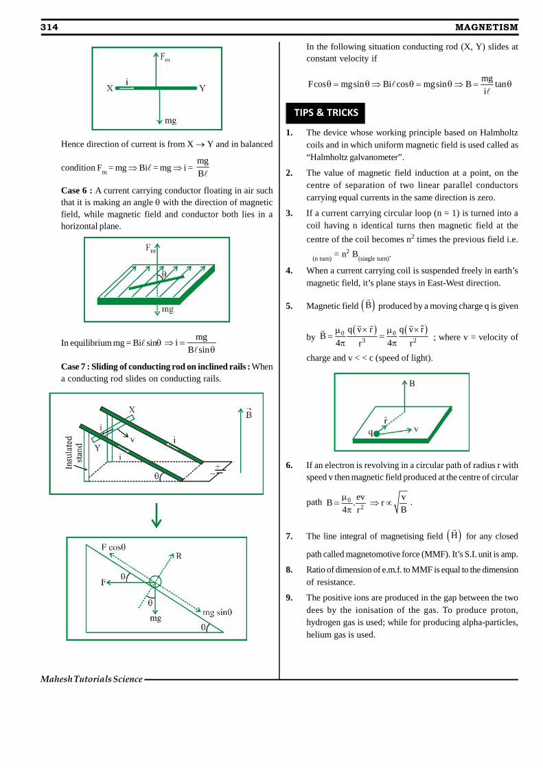
If no magnetic field is present, the loop will still open intoa circle as in it’s adjacent parts current will be in oppositedirection and opposite currents repel each other.
Case 2 : Equilibrium of a current carrying conductor :When a finite length current carrying wire is kept parallel toanother infinite length current carrying wire, it can suspendfreely in air as shown below
Lakshya Educare
MAGNETISM 313
In both the situations for equilibrium of XY it’s downward
weight = upward magnetic force i.e. 0 1 22i img . .
4 h
* In the first case if wire XY is slightly displaced from itsequilibrium position, it executes SHM and it’s time period
is given byh
T 2g
.
* If direction of current in movable wire is reversed thenit’s instantaneous acceleration produced is 2g.
Case 3 : Current carrying wire and circular loop : If acurrent carrying straight wire is placed in the magnetic fieldof current carrying circular loop.
Wire is placed in the perpendicular magnetic field due tocoil at it’s centre, so it will experience a maximum force
0 12
iF Bi i
2r
Wire is placed along the axis of coil so magnetic fieldproduced by the coil is parallel to the wire. Hence it will notexperience any force.
Case 4 : Current carrying spring : If current is passedthrough a spring, then it will contract because current willflow through all the turns in the same direction.
If current makes to flow through spring, then spring willcontract and weight lift up.
If switch is closed then current start flowing, spring willexecute oscillation in vertical plane.
Case 5 : Tension less strings : In the following figure thevalue and direction of current through the conductor XY sothat strings becomes tensionless ?
Strings becomes tensionless if weight of conductor XY
balanced by magnetic force (Fm
).
314 MAGNETISM
Mahesh Tutorials Science
Hence direction of current is from X Y and in balanced
condition Fm
= mg Bi = mg i =mg
B
Case 6 : A current carrying conductor floating in air suchthat it is making an angle with the direction of magneticfield, while magnetic field and conductor both lies in ahorizontal plane.
In equilibrium mg = Bi sinmg
iB sin
Case 7 : Sliding of conducting rod on inclined rails : Whena conducting rod slides on conducting rails.
In the following situation conducting rod (X, Y) slides atconstant velocity if
mgFcos mgsin Bi cos mgsin B tan
i
TIPS & TRICKS
1. The device whose working principle based on Halmholtzcoils and in which uniform magnetic field is used called as“Halmholtz galvanometer”.
2. The value of magnetic field induction at a point, on thecentre of separation of two linear parallel conductorscarrying equal currents in the same direction is zero.
3. If a current carrying circular loop (n = 1) is turned into acoil having n identical turns then magnetic field at the
centre of the coil becomes n2 times the previous field i.e.
B
(n turn) = n2 B
(single turn).
4. When a current carrying coil is suspended freely in earth’smagnetic field, it’s plane stays in East-West direction.
5. Magnetic field B
produced by a moving charge q is given
by 0 0
3 2
ˆq v r q v rB
4 4r r
; where v = velocity of
charge and v < < c (speed of light).
6. If an electron is revolving in a circular path of radius r withspeed v then magnetic field produced at the centre of circular
path 02
ev vB . r
4 Br
.
7. The line integral of magnetising field H
for any closed
path called magnetomotive force (MMF). It’s S.I. unit is amp.
8. Ratio of dimension of e.m.f. to MMF is equal to the dimensionof resistance.
9. The positive ions are produced in the gap between the twodees by the ionisation of the gas. To produce proton,hydrogen gas is used; while for producing alpha-particles,helium gas is used.
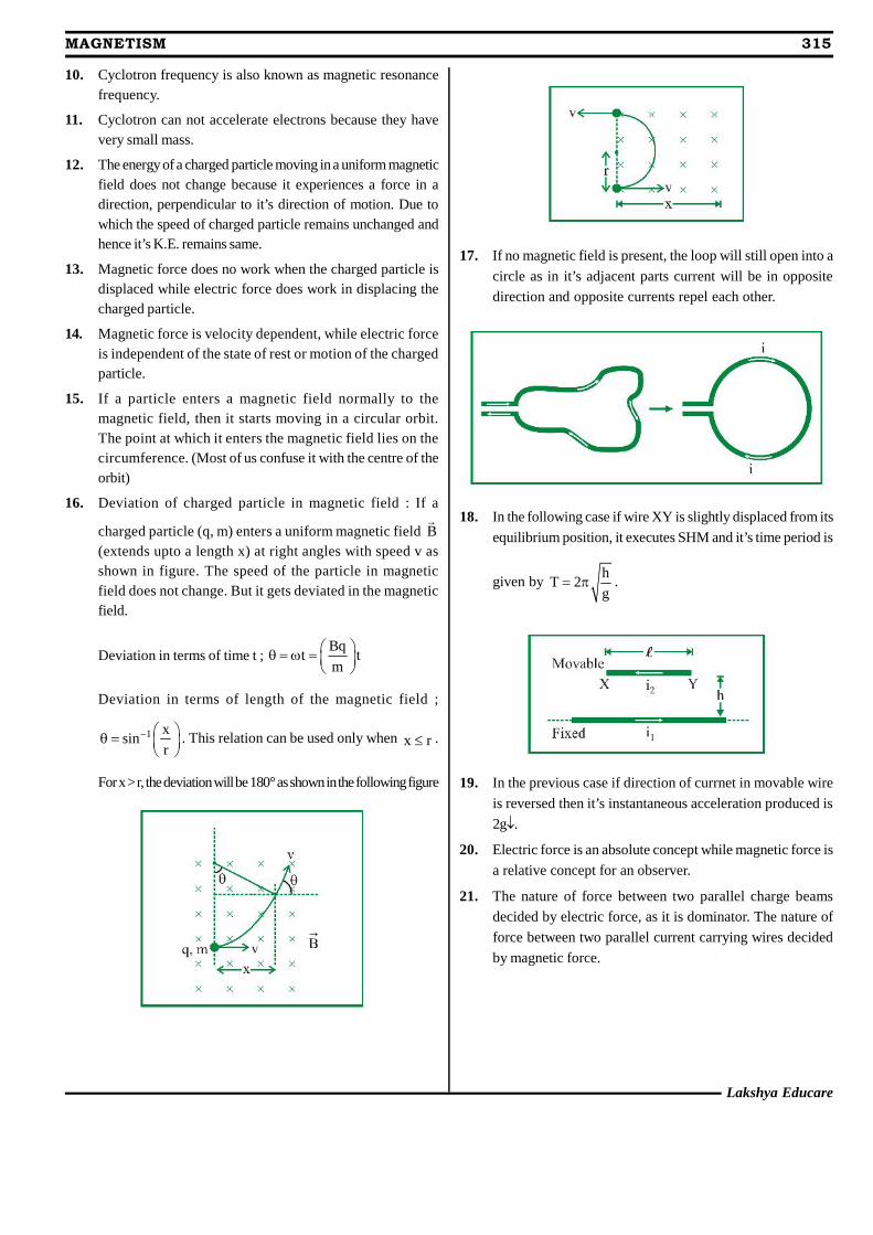
Lakshya Educare
MAGNETISM 315
10. Cyclotron frequency is also known as magnetic resonancefrequency.
11. Cyclotron can not accelerate electrons because they havevery small mass.
12. The energy of a charged particle moving in a uniform magneticfield does not change because it experiences a force in adirection, perpendicular to it’s direction of motion. Due towhich the speed of charged particle remains unchanged andhence it’s K.E. remains same.
13. Magnetic force does no work when the charged particle isdisplaced while electric force does work in displacing thecharged particle.
14. Magnetic force is velocity dependent, while electric forceis independent of the state of rest or motion of the chargedparticle.
15. If a particle enters a magnetic field normally to themagnetic field, then it starts moving in a circular orbit.The point at which it enters the magnetic field lies on thecircumference. (Most of us confuse it with the centre of theorbit)
16. Deviation of charged particle in magnetic field : If a
charged particle (q, m) enters a uniform magnetic field B
(extends upto a length x) at right angles with speed v asshown in figure. The speed of the particle in magneticfield does not change. But it gets deviated in the magneticfield.
Deviation in terms of time t ;Bq
t tm
Deviation in terms of length of the magnetic field ;
1 xsin
r
. This relation can be used only when x r .
For x > r, the deviation will be 180° as shown in the following figure
17. If no magnetic field is present, the loop will still open into a
circle as in it’s adjacent parts current will be in oppositedirection and opposite currents repel each other.
18. In the following case if wire XY is slightly displaced from its
equilibrium position, it executes SHM and it’s time period is
given byh
T 2g
.
19. In the previous case if direction of currnet in movable wire
is reversed then it’s instantaneous acceleration produced is2g.
20. Electric force is an absolute concept while magnetic force is
a relative concept for an observer.
21. The nature of force between two parallel charge beams
decided by electric force, as it is dominator. The nature of
force between two parallel current carrying wires decided
by magnetic force.
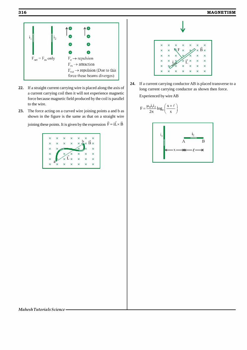
22. If a straight current carrying wire is placed along the axis ofa current carrying coil then it will not experience magneticforce because magnetic field produced by the coil is parallelto the wire.
23. The force acting on a curved wire joining points a and b asshown in the figure is the same as that on a straight wire
joining these points. It is given by the expression F iL B
24. If a current carrying conductor AB is placed transverse to along current carrying conductor as shown then force.
Experienced by wire AB
0 1 2e
i i xF log
2 x
316 MAGNETISM
Mahesh Tutorials Science
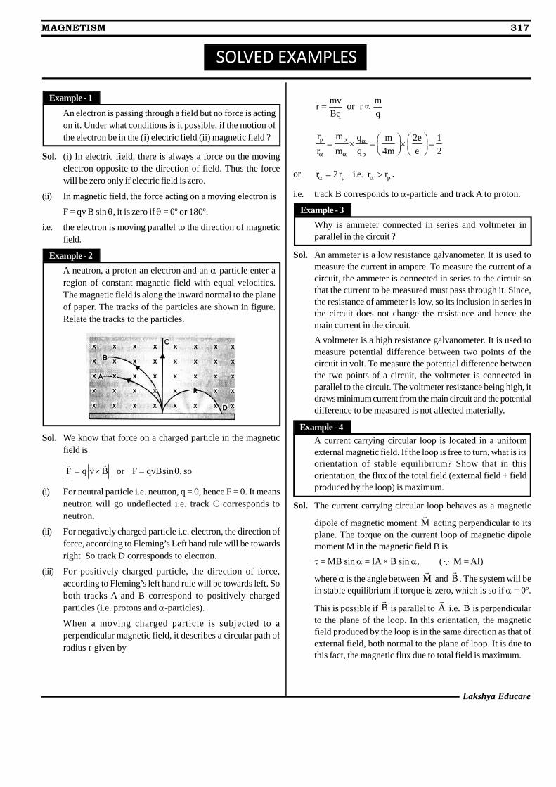
SOLVED EXAMPLES
An electron is passing through a field but no force is actingon it. Under what conditions is it possible, if the motion ofthe electron be in the (i) electric field (ii) magnetic field ?
Sol. (i) In electric field, there is always a force on the movingelectron opposite to the direction of field. Thus the forcewill be zero only if electric field is zero.
(ii) In magnetic field, the force acting on a moving electron is
F = qv B sin , it is zero if = 0º or 180º.
i.e. the electron is moving parallel to the direction of magneticfield.
A neutron, a proton an electron and an -particle enter aregion of constant magnetic field with equal velocities.The magnetic field is along the inward normal to the planeof paper. The tracks of the particles are shown in figure.Relate the tracks to the particles.
Sol. We know that force on a charged particle in the magneticfield is
F q v B or F qvBsin , so
(i) For neutral particle i.e. neutron, q = 0, hence F = 0. It meansneutron will go undeflected i.e. track C corresponds toneutron.
(ii) For negatively charged particle i.e. electron, the direction offorce, according to Fleming’s Left hand rule will be towardsright. So track D corresponds to electron.
(iii) For positively charged particle, the direction of force,according to Fleming’s left hand rule will be towards left. Soboth tracks A and B correspond to positively chargedparticles (i.e. protons and -particles).
When a moving charged particle is subjected to aperpendicular magnetic field, it describes a circular path ofradius r given by
mv mr or r
Bq q
p p
p
r m q m 2e 1
r m q 4m e 2
or p pr 2r i.e. r r .
i.e. track B corresponds to -particle and track A to proton.
Why is ammeter connected in series and voltmeter inparallel in the circuit ?
Sol. An ammeter is a low resistance galvanometer. It is used tomeasure the current in ampere. To measure the current of acircuit, the ammeter is connected in series to the circuit sothat the current to be measured must pass through it. Since,the resistance of ammeter is low, so its inclusion in series inthe circuit does not change the resistance and hence themain current in the circuit.
A voltmeter is a high resistance galvanometer. It is used tomeasure potential difference between two points of thecircuit in volt. To measure the potential difference betweenthe two points of a circuit, the voltmeter is connected inparallel to the circuit. The voltmeter resistance being high, itdraws minimum current from the main circuit and the potentialdifference to be measured is not affected materially.
A current carrying circular loop is located in a uniformexternal magnetic field. If the loop is free to turn, what is itsorientation of stable equilibrium? Show that in thisorientation, the flux of the total field (external field + fieldproduced by the loop) is maximum.
Sol. The current carrying circular loop behaves as a magnetic
dipole of magnetic moment M
acting perpendicular to itsplane. The torque on the current loop of magnetic dipolemoment M in the magnetic field B is
= MB sin = IA × B sin , ( M = AI)
where is the angle between M
and B
. The system will bein stable equilibrium if torque is zero, which is so if = 0º.
This is possible if B
is parallel to A
i.e. B
is perpendicularto the plane of the loop. In this orientation, the magneticfield produced by the loop is in the same direction as that ofexternal field, both normal to the plane of loop. It is due tothis fact, the magnetic flux due to total field is maximum.
Example - 1
Example - 2
Example - 3
Example - 4
Lakshya Educare
MAGNETISM 317
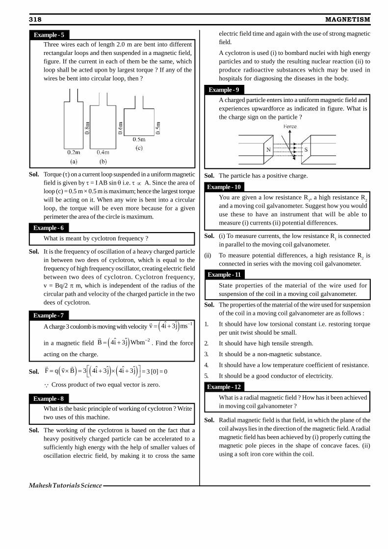
318 MAGNETISM
Mahesh Tutorials Science
Three wires each of length 2.0 m are bent into differentrectangular loops and then suspended in a magnetic field,figure. If the current in each of them be the same, whichloop shall be acted upon by largest torque ? If any of thewires be bent into circular loop, then ?
Sol. Torque () on a current loop suspended in a uniform magneticfield is given by = I AB sin i.e. A. Since the area ofloop (c) = 0.5 m × 0.5 m is maximum; hence the largest torquewill be acting on it. When any wire is bent into a circularloop, the torque will be even more because for a givenperimeter the area of the circle is maximum.
What is meant by cyclotron frequency ?
Sol. It is the frequency of oscillation of a heavy charged particlein between two dees of cyclotron, which is equal to thefrequency of high frequency oscillator, creating electric fieldbetween two dees of cyclotron. Cyclotron frequency,v = Bq/2 m, which is independent of the radius of thecircular path and velocity of the charged particle in the twodees of cyclotron.
A charge 3 coulomb is moving with velocity 1ˆ ˆv 4i 3j ms
in a magnetic field 2ˆ ˆB 4i 3j Wbm
. Find the force
acting on the charge.
Sol. ˆ ˆ ˆ ˆF q v B 3 4i 3j 4i 3j
= 3 [0] = 0
Cross product of two equal vector is zero.
What is the basic principle of working of cyclotron ? Writetwo uses of this machine.
Sol. The working of the cyclotron is based on the fact that aheavy positively charged particle can be accelerated to asufficiently high energy with the help of smaller values ofoscillation electric field, by making it to cross the same
electric field time and again with the use of strong magneticfield.
A cyclotron is used (i) to bombard nuclei with high energyparticles and to study the resulting nuclear reaction (ii) toproduce radioactive substances which may be used inhospitals for diagnosing the diseases in the body.
A charged particle enters into a uniform magnetic field andexperiences upwardforce as indicated in figure. What isthe charge sign on the particle ?
Sol. The particle has a positive charge.
You are given a low resistance R1, a high resistance R
2
and a moving coil galvanometer. Suggest how you woulduse these to have an instrument that will be able tomeasure (i) currents (ii) potential differences.
Sol. (i) To measure currents, the low resistance R1 is connected
in parallel to the moving coil galvanometer.
(ii) To measure potential differences, a high resistance R2 is
connected in series with the moving coil galvanometer.
State properties of the material of the wire used forsuspension of the coil in a moving coil galvanometer.
Sol. The properties of the material of the wire used for suspensionof the coil in a moving coil galvanometer are as follows :
1. It should have low torsional constant i.e. restoring torqueper unit twist should be small.
2. It should have high tensile strength.
3. It should be a non-magnetic substance.
4. It should have a low temperature coefficient of resistance.
5. It should be a good conductor of electricity.
What is a radial magnetic field ? How has it been achievedin moving coil galvanometer ?
Sol. Radial magnetic field is that field, in which the plane of thecoil always lies in the direction of the magnetic field. A radialmagnetic field has been achieved by (i) properly cutting themagnetic pole pieces in the shape of concave faces. (ii)using a soft iron core within the coil.
Example - 5
Example - 6
Example - 7
Example - 8
Example - 9
Example - 10
Example - 11
Example - 12
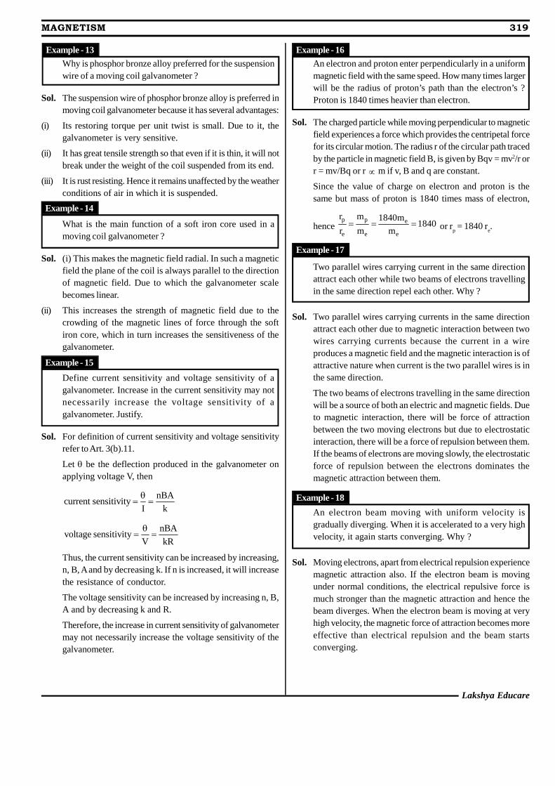
Lakshya Educare
MAGNETISM 319
Why is phosphor bronze alloy preferred for the suspensionwire of a moving coil galvanometer ?
Sol. The suspension wire of phosphor bronze alloy is preferred inmoving coil galvanometer because it has several advantages:
(i) Its restoring torque per unit twist is small. Due to it, thegalvanometer is very sensitive.
(ii) It has great tensile strength so that even if it is thin, it will notbreak under the weight of the coil suspended from its end.
(iii) It is rust resisting. Hence it remains unaffected by the weatherconditions of air in which it is suspended.
What is the main function of a soft iron core used in amoving coil galvanometer ?
Sol. (i) This makes the magnetic field radial. In such a magneticfield the plane of the coil is always parallel to the directionof magnetic field. Due to which the galvanometer scalebecomes linear.
(ii) This increases the strength of magnetic field due to thecrowding of the magnetic lines of force through the softiron core, which in turn increases the sensitiveness of thegalvanometer.
Define current sensitivity and voltage sensitivity of agalvanometer. Increase in the current sensitivity may notnecessarily increase the voltage sensitivity of agalvanometer. Justify.
Sol. For definition of current sensitivity and voltage sensitivityrefer to Art. 3(b).11.
Let be the deflection produced in the galvanometer onapplying voltage V, then
nBAcurrent sensitivity
I k
nBAvoltage sensitivity
V kR
Thus, the current sensitivity can be increased by increasing,n, B, A and by decreasing k. If n is increased, it will increasethe resistance of conductor.
The voltage sensitivity can be increased by increasing n, B,A and by decreasing k and R.
Therefore, the increase in current sensitivity of galvanometermay not necessarily increase the voltage sensitivity of thegalvanometer.
An electron and proton enter perpendicularly in a uniformmagnetic field with the same speed. How many times largerwill be the radius of proton’s path than the electron’s ?Proton is 1840 times heavier than electron.
Sol. The charged particle while moving perpendicular to magneticfield experiences a force which provides the centripetal forcefor its circular motion. The radius r of the circular path tracedby the particle in magnetic field B, is given by Bqv = mv2/r orr = mv/Bq or r m if v, B and q are constant.
Since the value of charge on electron and proton is thesame but mass of proton is 1840 times mass of electron,
hencep p e
e e e
r m 1840m1840
r m m or r
p = 1840 r
e.
Two parallel wires carrying current in the same directionattract each other while two beams of electrons travellingin the same direction repel each other. Why ?
Sol. Two parallel wires carrying currents in the same directionattract each other due to magnetic interaction between twowires carrying currents because the current in a wireproduces a magnetic field and the magnetic interaction is ofattractive nature when current is the two parallel wires is inthe same direction.
The two beams of electrons travelling in the same directionwill be a source of both an electric and magnetic fields. Dueto magnetic interaction, there will be force of attractionbetween the two moving electrons but due to electrostaticinteraction, there will be a force of repulsion between them.If the beams of electrons are moving slowly, the electrostaticforce of repulsion between the electrons dominates themagnetic attraction between them.
An electron beam moving with uniform velocity isgradually diverging. When it is accelerated to a very highvelocity, it again starts converging. Why ?
Sol. Moving electrons, apart from electrical repulsion experiencemagnetic attraction also. If the electron beam is movingunder normal conditions, the electrical repulsive force ismuch stronger than the magnetic attraction and hence thebeam diverges. When the electron beam is moving at veryhigh velocity, the magnetic force of attraction becomes moreeffective than electrical repulsion and the beam startsconverging.
Example - 13
Example - 14
Example - 15
Example - 16
Example - 17
Example - 18
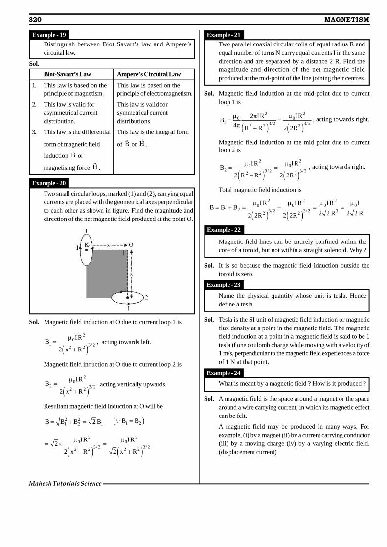
320 MAGNETISM
Mahesh Tutorials Science
Distinguish between Biot Savart’s law and Ampere’scircuital law.
Sol.
Biot-Savart’s Law Ampere’s Circuital Law
1. This law is based on the This law is based on theprinciple of magnetism. principle of electromagnetism.
2. This law is valid for This law is valid forasymmetrical current symmetrical currentdistribution. distributions.
3. This law is the differential This law is the integral form
form of magnetic field of B
or H
.
induction B
or
magnetising force H
.
Two small circular loops, marked (1) and (2), carrying equalcurrents are placed with the geometrical axes perpendicularto each other as shown in figure. Find the magnitude anddirection of the net magnetic field produced at the point O.
Sol. Magnetic field induction at O due to current loop 1 is
2
01 3/ 22 2
IRB ,
2 x R
acting towards left.
Magnetic field induction at O due to current loop 2 is
2
02 3/ 22 2
IRB
2 x R
acting vertically upwards.
Resultant magnetic field induction at O will be
2 21 2 1B B B 2 B 1 2B B
2 2
0 03/ 2 3/ 22 2 2 2
IR IR2
2 x R 2 x R
Two parallel coaxial circular coils of equal radius R andequal number of turns N carry equal currents I in the samedirection and are separated by a distance 2 R. Find themagnitude and direction of the net magnetic fieldproduced at the mid-point of the line joining their centres.
Sol. Magnetic field induction at the mid-point due to currentloop 1 is
22
0 01 3/ 2 3/ 22 2 2
IR2 IRB
4 R R 2 2R
, acting towards right.
Magnetic field induction at the mid point due to currentloop 2 is
2 2
0 02 3/ 2 3/ 22 2 3
IR IRB
2 R R 2 2R
, acting towards right.
Total magnetic field induction is
2 2 2
0 0 0 01 2 3/ 2 3/ 2 32 2
I R I R I R IB B B
2 2 R 2 2 R2 2R 2 2R
Magnetic field lines can be entirely confined within thecore of a toroid, but not within a straight solenoid. Why ?
Sol. It is so because the magnetic field idnuction outside thetoroid is zero.
Name the physical quantity whose unit is tesla. Hencedefine a tesla.
Sol. Tesla is the SI unit of magnetic field induction or magneticflux density at a point in the magnetic field. The magneticfield induction at a point in a magnetic field is said to be 1tesla if one coulomb charge while moving with a velocity of1 m/s, perpendicular to the magnetic field experiences a forceof 1 N at that point.
What is meant by a magnetic field ? How is it produced ?
Sol. A magnetic field is the space around a magnet or the spacearound a wire carrying current, in which its magnetic effectcan be felt.
A magnetic field may be produced in many ways. Forexample, (i) by a magnet (ii) by a current carrying conductor(iii) by a moving charge (iv) by a varying electric field.(displacement current)
Example - 19
Example - 20
Example - 21
Example - 22
Example - 23
Example - 24
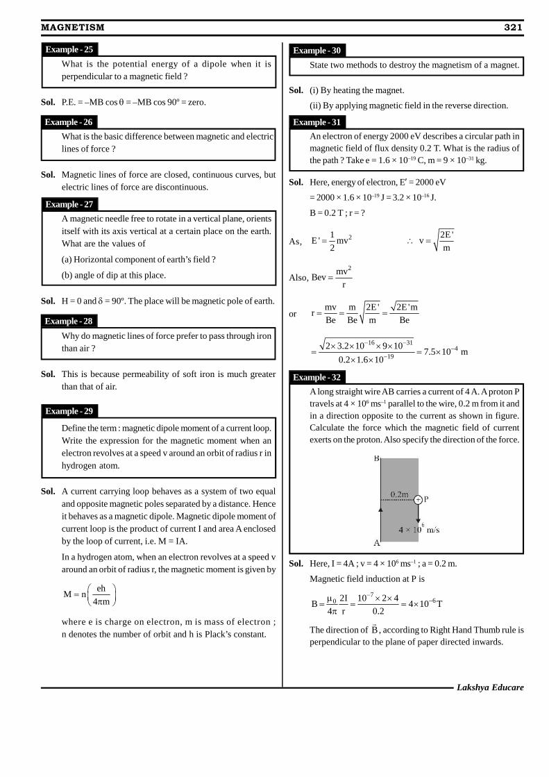
Lakshya Educare
MAGNETISM 321
What is the potential energy of a dipole when it isperpendicular to a magnetic field ?
Sol. P.E. = –MB cos = –MB cos 90º = zero.
What is the basic difference between magnetic and electriclines of force ?
Sol. Magnetic lines of force are closed, continuous curves, butelectric lines of force are discontinuous.
A magnetic needle free to rotate in a vertical plane, orientsitself with its axis vertical at a certain place on the earth.What are the values of
(a) Horizontal component of earth’s field ?
(b) angle of dip at this place.
Sol. H = 0 and = 90º. The place will be magnetic pole of earth.
Why do magnetic lines of force prefer to pass through ironthan air ?
Sol. This is because permeability of soft iron is much greaterthan that of air.
Define the term : magnetic dipole moment of a current loop.Write the expression for the magnetic moment when anelectron revolves at a speed v around an orbit of radius r inhydrogen atom.
Sol. A current carrying loop behaves as a system of two equaland opposite magnetic poles separated by a distance. Henceit behaves as a magnetic dipole. Magnetic dipole moment ofcurrent loop is the product of current I and area A enclosedby the loop of current, i.e. M = IA.
In a hydrogen atom, when an electron revolves at a speed varound an orbit of radius r, the magnetic moment is given by
ehM n
4 m
where e is charge on electron, m is mass of electron ;n denotes the number of orbit and h is Plack’s constant.
State two methods to destroy the magnetism of a magnet.
Sol. (i) By heating the magnet.
(ii) By applying magnetic field in the reverse direction.
An electron of energy 2000 eV describes a circular path inmagnetic field of flux density 0.2 T. What is the radius ofthe path ? Take e = 1.6 × 10⁻¹⁹ C, m = 9 × 10–31 kg.
Sol. Here, energy of electron, E’ = 2000 eV
= 2000 × 1.6 × 10–19 J = 3.2 × 10⁻¹⁶ J.
B = 0.2 T ; r = ?
As, 21E ' mv
2
2E 'v
m
Also,2mv
Bevr
ormv m 2E' 2E 'm
rBe Be m Be
16 314
19
2 3.2 10 9 107.5 10 m
0.2 1.6 10
A long straight wire AB carries a current of 4 A. A proton Ptravels at 4 × 10⁶ ms–1 parallel to the wire, 0.2 m from it andin a direction opposite to the current as shown in figure.Calculate the force which the magnetic field of currentexerts on the proton. Also specify the direction of the force.
Sol. Here, I = 4A ; v = 4 × 10⁶ ms–1 ; a = 0.2 m.
Magnetic field induction at P is
760 2I 10 2 4
B 4 10 T4 r 0.2
The direction of B
, according to Right Hand Thumb rule isperpendicular to the plane of paper directed inwards.
Example - 25
Example - 26
Example - 27
Example - 28
Example - 29
Example - 30
Example - 31
Example - 32
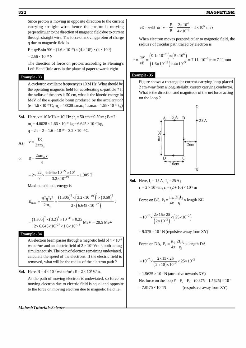
322 MAGNETISM
Mahesh Tutorials Science
Since proton is moving in opposite direction to the currentcarrying straight wire, hence the proton is movingperpendicular to the direction of magnetic field due to currentthrough straight wire. The force on moving proton of chargeq due to magnetic field is
F = qvB sin 90º = (1.6 × 10–19) × (4 × 106) × (4 × 10–6)
= 2.56 × 10⁻¹⁸ N
The direction of force on proton, according to Fleming’sLeft Hand Rule acts in the plane of paper towards right.
A cyclotron oscillator frequency is 10 M Hz. What should bethe operating magnetic field for accelerating -particle ? Ifthe radius of the dees is 50 cm, what is the kinetic energy inMeV of the -particle beam produced by the accelerator?(e = 1.6 × 10⁻¹⁹ C ; m = 4.0028 a.m.u. ; 1 a.m.u. = 1.66 × 10⁻²⁷ kg)
Sol. Here, v = 10 MHz = 107 Hz ; r0 = 50 cm = 0.50 m ; B = ?
m = 4.0028 × 1.66 × 10–27 kg = 6.645 × 10⁻²⁷ kg,
q = 2 e = 2 × 1.6 × 10–19 = 3.2 × 10⁻¹⁹ C.
As,Bq
v2 m
or2 m v
Bq
27 7
19
22 6.645 10 102 1.305 T
7 3.2 10
Maximum kinetic energy is
22 2192 2 2
max 27
1.305 3.2 10 0.50B q rE J
2m 2 6.645 10
2 2 38
27 13
1.305 3.2 10 0.25MeV 20.5 MeV
2 6.645 10 1.6 10
An electron beam passes through a magnetic field of 4 × 10⁻³
weber/m2 and an electric field of 2 × 10⁴ Vm–1, both actingsimultaneously. The path of electron remaining undeviated,calculate the speed of the electrons. If the electric field isremoved, what will be the radius of the electron path ?
Sol. Here, B = 4 × 10⁻³ weber/m2 ; E = 2 × 10⁴ V/m.
As the path of moving electron is undeviated, so force onmoving electron due to electric field is equal and oppositeto the force on moving electron due to magnetic field i.e.
46
3
E 2 10eE evB or v 5 10 m / s
B 4 10
When electron moves perpendicular to magnetic field, theradius r of circular path traced by electron is
31 63
19 3
9.1 10 5 10mvr 7.11 10 m 7.11 mm
eB 1.6 10 4 10
Figure shows a rectangular current-carrying loop placed2 cm away from a long, straight, current carrying conductor.What is the direction and magnitude of the net force actingon the loop ?
Sol. Here, I1 = 15 A ; I
2 = 25 A ;
r1 = 2 × 10⁻² m ; r
2 = (2 + 10) × 10–2 m
Force on BC, 0 1 21
1
2I IF length BC
4 r
7 22
2 15 2510 25 10
2 10
= 9.375 × 10⁻⁴ N (repulsive, away from XY)
Force on DA, 0 1 22
2
2I IF length DA
4 r
7 2
2
2 15 2510 25 10
2 10 10
= 1.5625 × 10⁻⁴ N (attractive towards XY)
Net force on the loop F = F1 – F
2 = (0.375 – 1.5625) × 10–4
= 7.8175 × 10⁻⁴ N (respulsive, away from XY)
Example - 33
Example - 34
Example - 35
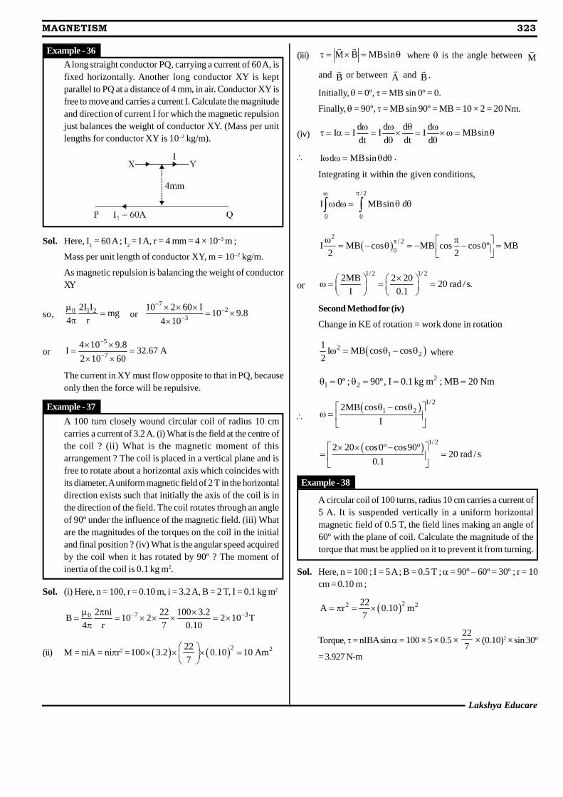
Lakshya Educare
MAGNETISM 323
A long straight conductor PQ, carrying a current of 60 A, isfixed horizontally. Another long conductor XY is keptparallel to PQ at a distance of 4 mm, in air. Conductor XY isfree to move and carries a current I. Calculate the magnitudeand direction of current I for which the magnetic repulsionjust balances the weight of conductor XY. (Mass per unitlengths for conductor XY is 10–2 kg/m).
Sol. Here, I1 = 60 A ; I
2 = I A, r = 4 mm = 4 × 10⁻³ m ;
Mass per unit length of conductor XY, m = 10–2 kg/m.
As magnetic repulsion is balancing the weight of conductorXY
so, 0 1 22I Img
4 r
or
72
3
10 2 60 I10 9.8
4 10
or5
7
4 10 9.8I 32.67 A
2 10 60
The current in XY must flow opposite to that in PQ, becauseonly then the force will be repulsive.
A 100 turn closely wound circular coil of radius 10 cmcarries a current of 3.2 A. (i) What is the field at the centre ofthe coil ? (ii) What is the magnetic moment of thisarrangement ? The coil is placed in a vertical plane and isfree to rotate about a horizontal axis which coincides withits diameter. A uniform magnetic field of 2 T in the horizontaldirection exists such that initially the axis of the coil is inthe direction of the field. The coil rotates through an angleof 90º under the influence of the magnetic field. (iii) Whatare the magnitudes of the torques on the coil in the initialand final position ? (iv) What is the angular speed acquiredby the coil when it has rotated by 90º ? The moment ofinertia of the coil is 0.1 kg m2.
Sol. (i) Here, n = 100, r = 0.10 m, i = 3.2 A, B = 2 T, I = 0.1 kg m2
7 30 2 ni 22 100 3.2B 10 2 2 10 T
4 r 7 0.10
(ii) M = niA = nir2 = 2 222100 3.2 0.10 10 Am
7
(iii) M B MBsin
where is the angle between M
and B
or between A
and B
.
Initially, = 0º, = MB sin 0º = 0.
Finally, = 90º, = MB sin 90º = MB = 10 × 2 = 20 Nm.
(iv)d d d d
I I I I MBsindt d dt d
I d MBsin d .
Integrating it within the given conditions,
/ 2
0 0
I d MBsin d
2
/ 2
0I MB cos MB cos cos0º MB
2 2
or1/ 2 1/ 2
2MB 2 2020 rad / s.
I 0.1
Second Method for (iv)
Change in KE of rotation = work done in rotation
21 2
1I MB cos cos
2 where
21 20º ; 90º , I 0.1 kg m ; MB 20 Nm
1/ 2
1 22MB cos cos
I
1/ 22 20 cos0º cos90º
20 rad / s0.1
A circular coil of 100 turns, radius 10 cm carries a current of5 A. It is suspended vertically in a uniform horizontalmagnetic field of 0.5 T, the field lines making an angle of60º with the plane of coil. Calculate the magnitude of thetorque that must be applied on it to prevent it from turning.
Sol. Here, n = 100 ; I = 5 A ; B = 0.5 T ; = 90º – 60º = 30º ; r = 10cm = 0.10 m ;
22 222A r 0.10 m
7
Torque, = nIBA sin = 100 × 5 × 0.5 ×22
7 × (0.10)2 × sin 30º
= 3.927 N-m
Example - 36
Example - 37
Example - 38
324 MAGNETISM
Mahesh Tutorials Science
Compare the current sensitivity and voltage sensitivity ofthe following moving coil galvanometers :
Meter A : n = 30, A = 1.5 × 10⁻³ m2, B = 0.25 T, R = 20
Meter B : n = 35, A = 2.0 × 10⁻³ m2, B = 0.25 T, R = 30
You are given that the springs in the two metres have thesame torsional constants.
Sol. For metre A, n1 = 30, A
1 = 1.5 × 10⁻³ m2, B
1 = 0.25 T, R
1 = 20.
For metre B, n2 = 35, A
2 = 2.0 × 10⁻³ m2, B
2 = 0.25 T, R
2 = 30.
nBACurrent sensitivity of a meter
k
Current sensitivity of meter A
Current sensitivity of meter B
1 1 1 2 1 1 1
1 2 2 2 2 2 2
n B A k n B A
k n B A n B A 1 2k k
3
3
30 0.25 1.5 10 45 9
70 1435 0.25 2.0 10
Now, voltage sensitivity of a meternBA
kR
Voltage sensitivity of meter A
Voltage sensitivity of meter B
1 1 1 2 2 1 1 1 2
1 1 2 2 2 2 2 2 1
n B A k R n B A R
k R n B A n B A R
3
3
30 0.25 1.5 10 30 9 30 27
14 20 2835 0.25 2.0 10 20
The current sensitivity of a moving coil galvanometerincreases by 20% when its resistance is increased by a factor2. Calculate by what factor the voltage sensitivity changes.
Sol. Given,'s s s s
20 120I I I I ; R ' 2R
100 100
Then, initial voltage sensitivity, ss
IV
R
New voltage sensitivity,
'' ss s s
I 120 1 3V I V
R ' 100 2R 5
% decrease in voltage sensitivity'
s s
s
V V100
V
s s
s
3V V
5 100 40%V
A galvanometer having 30 divisions has a currentsensitivity of 20 A/division. It has a resistance of 25 .How will you convert it into an ammeter upto 1 ampere ?How will you convert this ammeter into a voltmeter up to 1volt ?
Sol. Current sensitivity = 20 A/div. = 20 × 10–6 A/div.
Current for full scale deflection, ig = 20 × 10–6 × 30
= 6 × 10⁻⁴ A
For converting galvanometer into ammeter the shunt required
4g
4g
I 6 10 25S .G 0.1050
I I 1 6 10
Resistance of ammeter formed,
GS 0.015 25G ' 0.015
G S 25 0.015
Conversion of ammeter into voltmeter
Here, Ig = 1 ampere, V = 1 volt, G’ = 0.015
Resistance to be used in series,
g
V 1R G ' 0.015 0.985
I 1
A resistance of 1980 is connected in series with avoltmeter, after which the scale division becomes 100 timeslarger. Find the resistance of voltmeter.
Sol. Let R be the resistance of voltmeter. Let n be the number ofdivisions in the voltmeter. The voltage recorded by eachdivision of voltmeter when current i
g flows through it is
ig R/n = V ...(i)
when resistance is connected in series of voltmeter then
ig (R + 1980)/n = 100 V ...(ii)
Dividing (ii) by (i), we get
R + 1980 = 100 R
or R = 1980/99 = 20
Example - 39
Example - 40
Example - 41
Example - 42
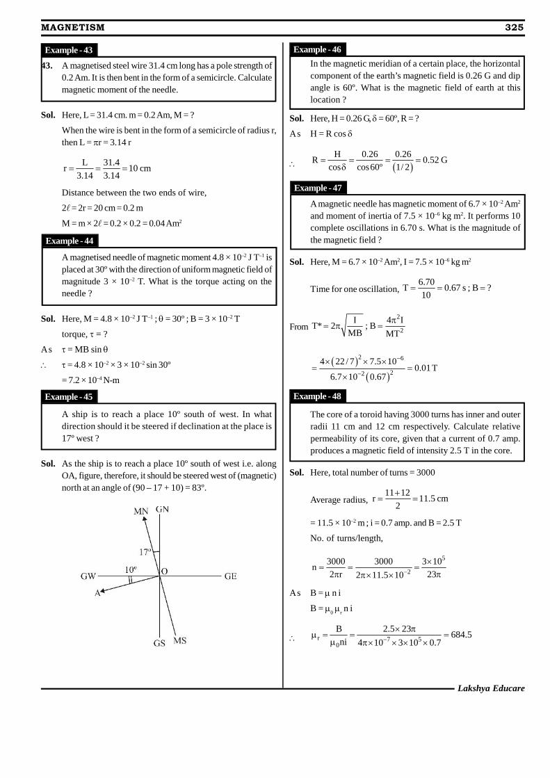
Lakshya Educare
MAGNETISM 325
43. A magnetised steel wire 31.4 cm long has a pole strength of0.2 Am. It is then bent in the form of a semicircle. Calculatemagnetic moment of the needle.
Sol. Here, L = 31.4 cm. m = 0.2 Am, M = ?
When the wire is bent in the form of a semicircle of radius r,then L = r = 3.14 r
L 31.4r 10 cm
3.14 3.14
Distance between the two ends of wire,
2 = 2r = 20 cm = 0.2 m
M = m × 2 = 0.2 × 0.2 = 0.04 Am2
A magnetised needle of magnetic moment 4.8 × 10⁻² J T–1 isplaced at 30º with the direction of uniform magnetic field ofmagnitude 3 × 10⁻² T. What is the torque acting on theneedle ?
Sol. Here, M = 4.8 × 10⁻² J T–1 ; = 30º ; B = 3 × 10⁻² T
torque, = ?
As = MB sin
= 4.8 × 10–2 × 3 × 10–2 sin 30º
= 7.2 × 10⁻⁴ N-m
A ship is to reach a place 10º south of west. In whatdirection should it be steered if declination at the place is17º west ?
Sol. As the ship is to reach a place 10º south of west i.e. alongOA, figure, therefore, it should be steered west of (magnetic)north at an angle of (90 – 17 + 10) = 83º.
In the magnetic meridian of a certain place, the horizontalcomponent of the earth’s magnetic field is 0.26 G and dipangle is 60º. What is the magnetic field of earth at thislocation ?
Sol. Here, H = 0.26 G, = 60º, R = ?
As H = R cos
H 0.26 0.26
R 0.52 Gcos cos60º 1/ 2
A magnetic needle has magnetic moment of 6.7 × 10⁻² Am2
and moment of inertia of 7.5 × 10⁻⁶ kg m2. It performs 10complete oscillations in 6.70 s. What is the magnitude ofthe magnetic field ?
Sol. Here, M = 6.7 × 10⁻² Am2, I = 7.5 × 10⁻⁶ kg m2
Time for one oscillation,6.70
T 0.67 s ; B ?10
From2
2
I 4 IT* 2 ; B
MB MT
2 6
22
4 22 / 7 7.5 100.01 T
6.7 10 0.67
The core of a toroid having 3000 turns has inner and outerradii 11 cm and 12 cm respectively. Calculate relativepermeability of its core, given that a current of 0.7 amp.produces a magnetic field of intensity 2.5 T in the core.
Sol. Here, total number of turns = 3000
Average radius,11 12
r 11.5 cm2
= 11.5 × 10⁻² m ; i = 0.7 amp. and B = 2.5 T
No. of turns/length,
5
2
3000 3000 3 10n
2 r 232 11.5 10
As B = n i
B = 0
r n i
r 7 50
B 2.5 23684.5
ni 4 10 3 10 0.7
Example - 43
Example - 44
Example - 45
Example - 46
Example - 47
Example - 48
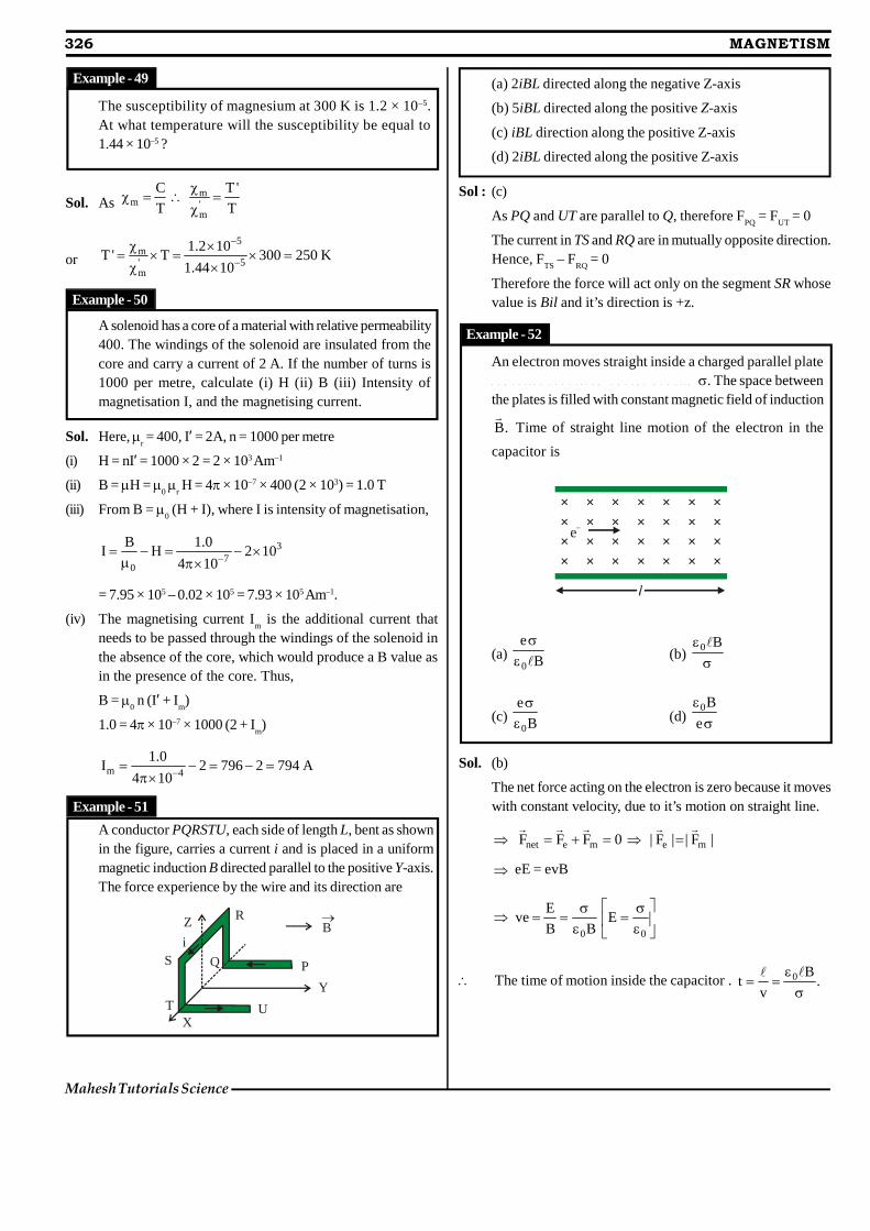
326 MAGNETISM
Mahesh Tutorials Science
The susceptibility of magnesium at 300 K is 1.2 × 10⁻⁵.At what temperature will the susceptibility be equal to1.44 × 10–5 ?
Sol. Asm
m 'm
C T'
T T
or5
m' 5m
1.2 10T ' T 300 250 K
1.44 10
A solenoid has a core of a material with relative permeability400. The windings of the solenoid are insulated from thecore and carry a current of 2 A. If the number of turns is1000 per metre, calculate (i) H (ii) B (iii) Intensity ofmagnetisation I, and the magnetising current.
Sol. Here, r = 400, I’ = 2A, n = 1000 per metre
(i) H = nI’ = 1000 × 2 = 2 × 10³ Am–1
(ii) B = H = 0
r H = 4× 10–7 × 400 (2 × 10³) = 1.0 T
(iii) From B = 0 (H + I), where I is intensity of magnetisation,
37
0
B 1.0I H 2 10
4 10
= 7.95 × 10⁵ – 0.02 × 105 = 7.93 × 10⁵ Am–1.
(iv) The magnetising current Im is the additional current that
needs to be passed through the windings of the solenoid inthe absence of the core, which would produce a B value asin the presence of the core. Thus,
B = 0 n (I’ + I
m)
1.0 = 4 × 10–7 × 1000 (2 + Im)
m 4
1.0I 2 796 2 794 A
4 10
A conductor PQRSTU, each side of length L, bent as shownin the figure, carries a current i and is placed in a uniformmagnetic induction B directed parallel to the positive Y-axis.The force experience by the wire and its direction are
i
Z
S
TX
U
Y
PQ
RB
Example - 49
Example - 50
(a) 2iBL directed along the negative Z-axis
(b) 5iBL directed along the positive Z-axis
(c) iBL direction along the positive Z-axis
(d) 2iBL directed along the positive Z-axis
Sol : (c)
As PQ and UT are parallel to Q, therefore FPQ
= FUT
= 0
The current in TS and RQ are in mutually opposite direction.Hence, F
TS – F
RQ = 0
Therefore the force will act only on the segment SR whosevalue is Bil and it’s direction is +z.
An electron moves straight inside a charged parallel platec a p a c i t o r a t u n i f o r m c h a r g e d e n s i t y . The space betweenthe plates is filled with constant magnetic field of induction
.B
Time of straight line motion of the electron in the
capacitor is
× × × × × × ×× × × × × × ×× × × × × × ×× × × × × × ×
e–
(a) B
e
0
(b) B0
(c) B
e
0
(d) e
B0
Sol. (b)
The net force acting on the electron is zero because it moveswith constant velocity, due to it’s motion on straight line.
0FFF menet
|F||F| me
eE = evB
00
EBB
Eve
The time of motion inside the capacitor . .B
vt 0
Example - 51
Example - 52
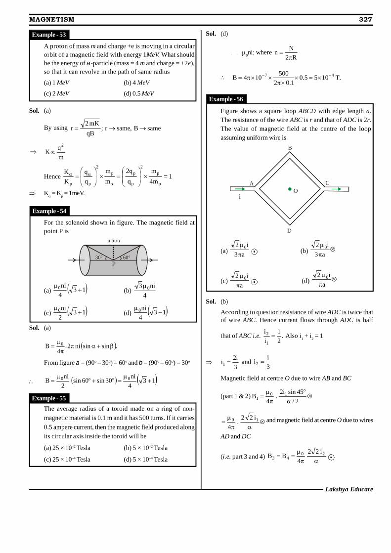
Lakshya Educare
MAGNETISM 327
A proton of mass m and charge +e is moving in a circularorbit of a magnetic field with energy 1MeV. What shouldbe the energy of -particle (mass = 4 m and charge = +2e),so that it can revolve in the path of same radius
(a) 1 MeV (b) 4 MeV
(c) 2 MeV (d) 0.5 MeV
Sol. (a)
By using sameB,samer;qB
mK2r
m
qK
2
Hence 1m4
m
q
q2
m
m
q
q
K
K
p
p2
p
pp2
pp
= 1
K = Kp = 1meV.
For the solenoid shown in figure. The magnetic field atpoint P is
n turn
30° 60°P
(a) 134
ni0
(b)4
ni3 0
(c) 132
ni0
(d) 134
ni0
Sol. (a)
.sinsinni2.4
B 0
From figure = (90o – 30o) = 60o and = (90o – 60o) = 30o
.134
ni30sin60sin
2
niB 00
The average radius of a toroid made on a ring of non-
magnetic material is 0.1 m and it has 500 turns. If it carries
0.5 ampere current, then the magnetic field produced along
its circular axis inside the toroid will be
(a) 25 × 10–2 Tesla (b) 5 × 10⁻² Tesla
(c) 25 × 10–4 Tesla (d) 5 × 10⁻⁴ Tesla
Sol. (d)
B = 0ni; where
R2
Nn
.T1055.01.02
500104B 47
Figure shows a square loop ABCD with edge length a.The resistance of the wire ABC is r and that of ADC is 2r.The value of magnetic field at the centre of the loopassuming uniform wire is
OA
B
C
D
i
(a) a3
i2 0
(b) a3
i2 0
(c)a
i2 0
(d) a
i2 0
Sol. (b)
According to question resistance of wire ADC is twice thatof wire ABC. Hence current flows through ADC is half
that of ABC i.e. .2
1
i
i
1
2 Also i1 + i
2 = 1
3
i2i1 and
3
ii2
Magnetic field at centre O due to wire AB and BC
(part 1 & 2)
2/
45sini2.
4B 10
1
10 i22
.4
and magnetic field at centre O due to wires
AD and DC
(i.e. part 3 and 4)
20
43i22
4BB
Example - 53
Example - 54
Example - 55
Example - 56
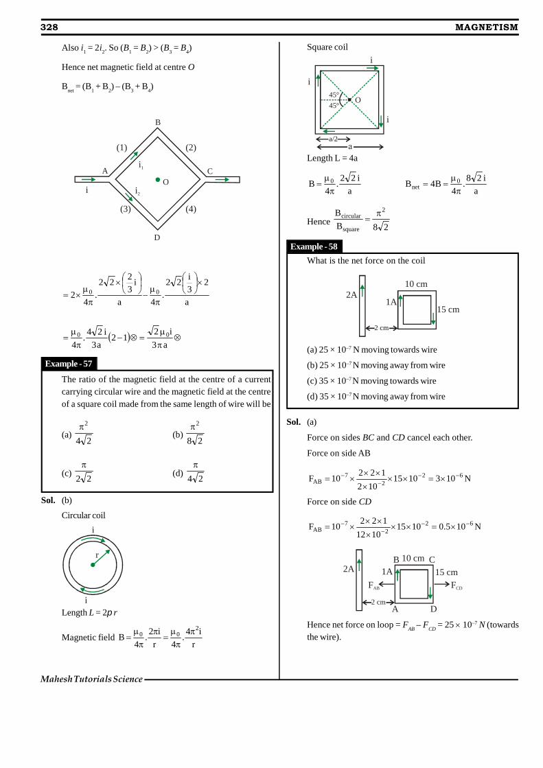
Also i1 = 2i
2. So (B
1 = B
2) > (B
3 = B
4)
Hence net magnetic field at centre O
Bnet
= (B1 + B
2) – (B
3 + B
4)
OA
B
C
D
i
i1
i2
(1) (2)
(4)(3)
a
23i
22.
4a
i32
22.
42 00
a3
i212
a3
i24.
400
The ratio of the magnetic field at the centre of a currentcarrying circular wire and the magnetic field at the centreof a square coil made from the same length of wire will be
(a)24
2(b)
28
2
(c)22
(d)
24
Sol. (b)
Circular coil
i
i
r
Length L = 2 r
Magnetic fieldr
i4.
4r
i2.
4B
200
Square coil
45°
45°
i
i
i
a/2
O
Length L = 4a
a
i22.
4B 0
a
i28.
4B4B 0
net
Hence28B
B 2
square
circular
What is the net force on the coil
2A1A
10 cm
15 cm
2 cm
(a) 25 × 10–7 N moving towards wire
(b) 25 × 10–7 N moving away from wire
(c) 35 × 10–7N moving towards wire
(d) 35 × 10–7 N moving away from wire
Sol. (a)
Force on sides BC and CD cancel each other.
Force on side AB
N1031015102
12210F 62
27
AB
Force on side CD
N105.010151012
12210F 62
27
AB
2A 1A
10 cm
15 cm
2 cm
FAB
A D
B C
FCD
Hence net force on loop = FAB
– FCD
= 25 10–7 N (towardsthe wire).
Example - 57
Example - 58
328 MAGNETISM
Mahesh Tutorials Science
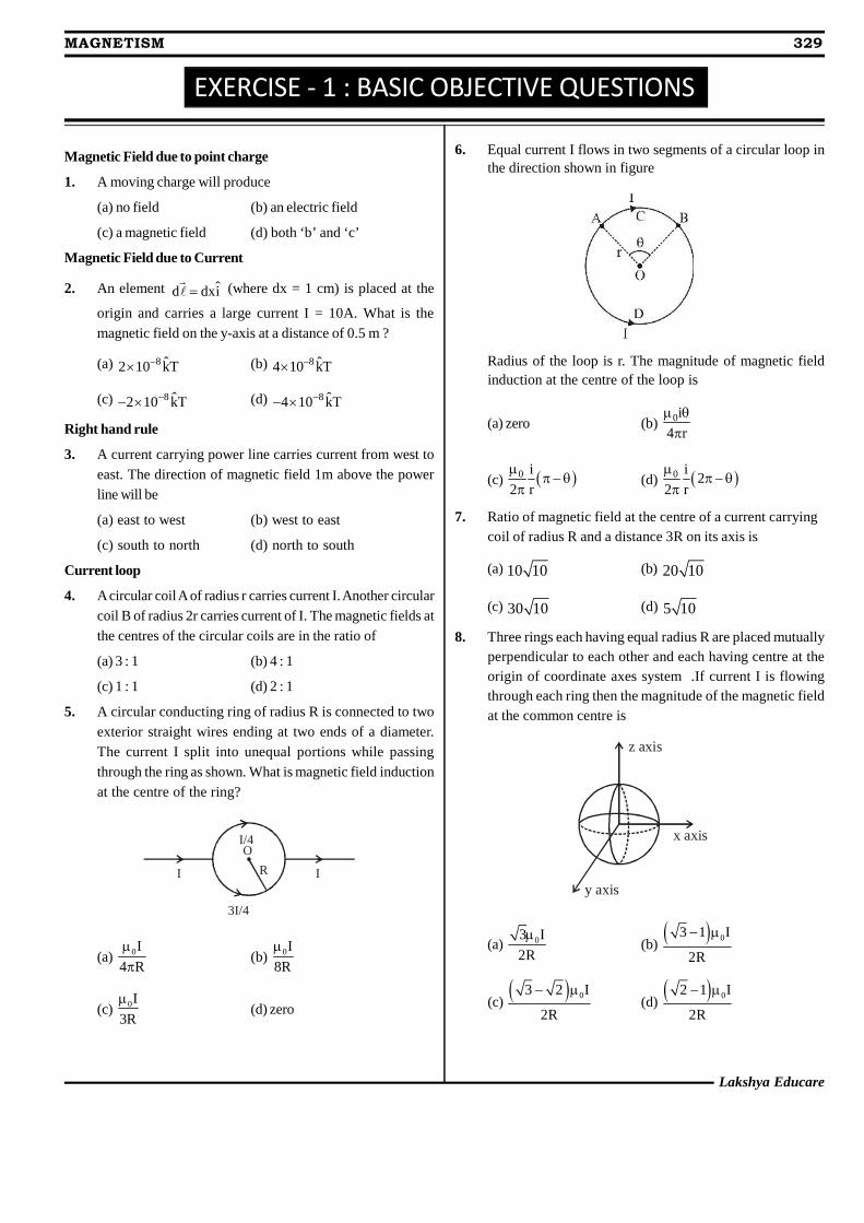
EXERCISE - 1 : BASIC OBJECTIVE QUESTIONS
Magnetic Field due to point charge
1. A moving charge will produce
(a) no field (b) an electric field
(c) a magnetic field (d) both ‘b’ and ‘c’
Magnetic Field due to Current
2. An element ˆd dxi (where dx = 1 cm) is placed at the
origin and carries a large current I = 10A. What is themagnetic field on the y-axis at a distance of 0.5 m ?
(a) 8 ˆ2 10 kT (b) 8 ˆ4 10 kT
(c) 8 ˆ2 10 kT (d) 8 ˆ4 10 kT
Right hand rule
3. A current carrying power line carries current from west toeast. The direction of magnetic field 1m above the powerline will be
(a) east to west (b) west to east
(c) south to north (d) north to south
Current loop
4. A circular coil A of radius r carries current I. Another circularcoil B of radius 2r carries current of I. The magnetic fields atthe centres of the circular coils are in the ratio of
(a) 3 : 1 (b) 4 : 1
(c) 1 : 1 (d) 2 : 1
5. A circular conducting ring of radius R is connected to twoexterior straight wires ending at two ends of a diameter.The current I split into unequal portions while passingthrough the ring as shown. What is magnetic field inductionat the centre of the ring?
O
RI I
I/4
3I/4
(a) 0I
4 R
(b) 0I
8R
(c) 0I
3R
(d) zero
6. Equal current I flows in two segments of a circular loop inthe direction shown in figure
Radius of the loop is r. The magnitude of magnetic fieldinduction at the centre of the loop is
(a) zero (b) 0i
4 r
(c) 0 i
2 r
(d) 0 i
22 r
7. Ratio of magnetic field at the centre of a current carryingcoil of radius R and a distance 3R on its axis is
(a) 10 10 (b) 20 10
(c) 30 10 (d) 5 10
8. Three rings each having equal radius R are placed mutuallyperpendicular to each other and each having centre at theorigin of coordinate axes system .If current I is flowingthrough each ring then the magnitude of the magnetic fieldat the common centre is
y axis
x axis
z axis
(a) 03 I
2R
(b) 03 1 I
2R
(c) 03 2 I
2R
(d) 02 1 I
2R
Lakshya Educare
MAGNETISM 329
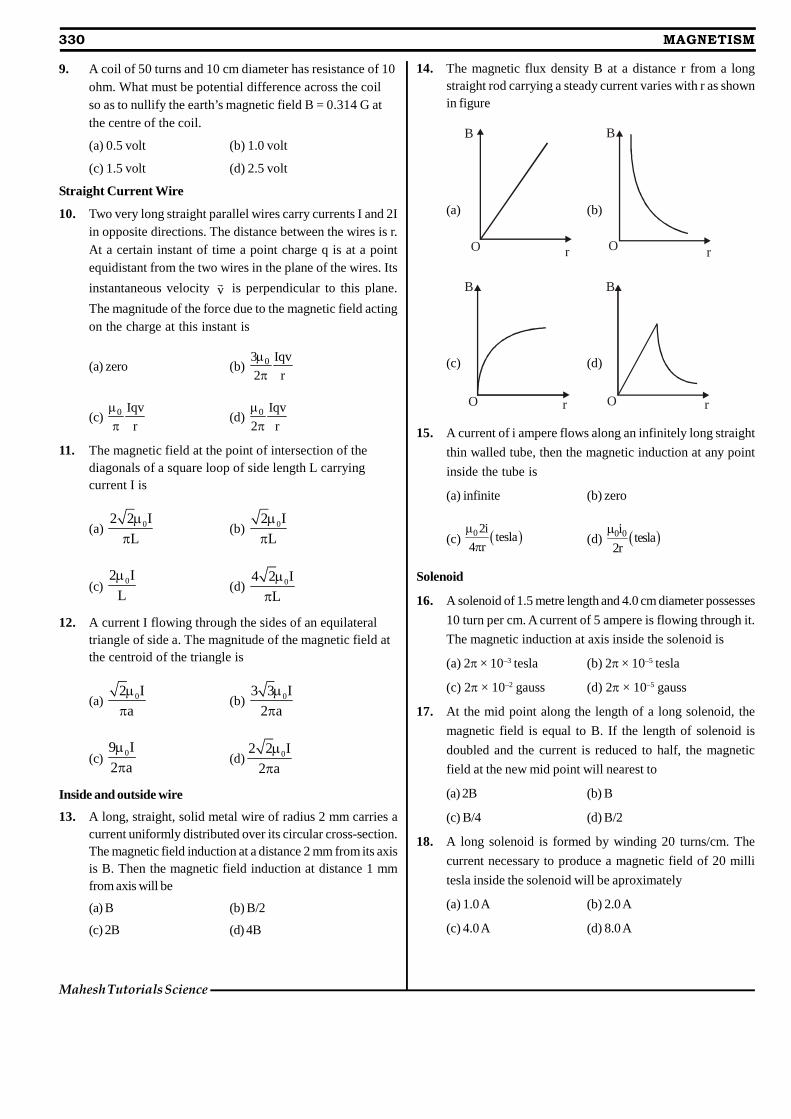
330 MAGNETISM
Mahesh Tutorials Science
9. A coil of 50 turns and 10 cm diameter has resistance of 10ohm. What must be potential difference across the coilso as to nullify the earth’s magnetic field B = 0.314 G atthe centre of the coil.
(a) 0.5 volt (b) 1.0 volt
(c) 1.5 volt (d) 2.5 volt
Straight Current Wire
10. Two very long straight parallel wires carry currents I and 2Iin opposite directions. The distance between the wires is r.At a certain instant of time a point charge q is at a pointequidistant from the two wires in the plane of the wires. Its
instantaneous velocity v is perpendicular to this plane.
The magnitude of the force due to the magnetic field actingon the charge at this instant is
(a) zero (b) 03 Iqv
2 r
(c) 0 Iqv
r
(d) 0 Iqv
2 r
11. The magnetic field at the point of intersection of thediagonals of a square loop of side length L carryingcurrent I is
(a) 02 2 I
L
(b) 02 I
L
(c) 02 I
L
(d) 04 2 I
L
12. A current I flowing through the sides of an equilateraltriangle of side a. The magnitude of the magnetic field atthe centroid of the triangle is
(a) 02 I
a
(b) 03 3 I
2 a
(c) 09 I
2 a
(d) 02 2 I
2 a
Inside and outside wire
13. A long, straight, solid metal wire of radius 2 mm carries acurrent uniformly distributed over its circular cross-section.The magnetic field induction at a distance 2 mm from its axisis B. Then the magnetic field induction at distance 1 mmfrom axis will be
(a) B (b) B/2
(c) 2B (d) 4B
14. The magnetic flux density B at a distance r from a longstraight rod carrying a steady current varies with r as shownin figure
(a)
B
rO
(b)
B
rO
(c)
O
B
r
(d)
B
rO
15. A current of i ampere flows along an infinitely long straight
thin walled tube, then the magnetic induction at any point
inside the tube is
(a) infinite (b) zero
(c) 02itesla
4 r
(d) 0 0i tesla2r
Solenoid
16. A solenoid of 1.5 metre length and 4.0 cm diameter possesses
10 turn per cm. A current of 5 ampere is flowing through it.
The magnetic induction at axis inside the solenoid is
(a) 2 × 10⁻³ tesla (b) 2 × 10⁻⁵ tesla
(c) 2 × 10⁻² gauss (d) 2× 10⁻⁵ gauss
17. At the mid point along the length of a long solenoid, the
magnetic field is equal to B. If the length of solenoid is
doubled and the current is reduced to half, the magnetic
field at the new mid point will nearest to
(a) 2B (b) B
(c) B/4 (d) B/2
18. A long solenoid is formed by winding 20 turns/cm. The
current necessary to produce a magnetic field of 20 milli
tesla inside the solenoid will be aproximately
(a) 1.0 A (b) 2.0 A
(c) 4.0 A (d) 8.0 A
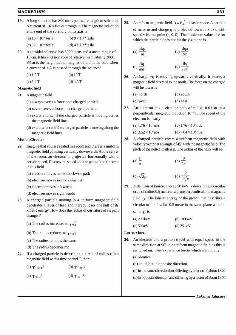
Lakshya Educare
MAGNETISM 331
19. A long solenoid has 800 turns per metre length of solenoid.A current of 1.6 A flows through it. The magnetic inductionat the end of the solenoid on its axis is
(a) 16 × 10–4 tesla (b) 8 × 10⁻⁴ tesla
(c) 32 × 10–4 tesla (d) 4 × 10⁻⁴ tesla
20. A toroidal solenoid has 3000 turns and a mean radius of10 cm. It has soft iron core of relative permeability 2000.What is the magnitude of magnetic field in the core whena current of 1 A is passed through the solenoid.
(a) 1.2 T (b) 12 T
(c) 5.6 T (d) 4.5 T
Magnetic field
21. A magnetic field
(a) always exerts a force on a charged particle
(b) never exerts a force on a charged particle
(c) exerts a force, if the charged particle is moving acrossthe magnetic field lines
(d) exerts a force, if the charged particle is moving along themagnetic field lines
Motion Circular
22. Imagine that you are seated in a room and there is a uniformmagnetic field pointing vertically downwards. At the centerof the room, an electron is projected horizontally with acertain speed. Discuss the speed and the path of the electronin this field.
(a) electron moves in anticlockwise path
(b) electron moves in clockwise path
(c) electron moves left wards
(d) electron moves right wards
23. A charged particle moving in a uniform magnetic fieldpenetrates a layer of lead and thereby loses one half of itskinetic energy. How does the radius of curvature of its pathchange ?
(a) The radius increases to r 2
(b) The radius reduces to r / 2
(c) The radius remains the same
(d) The radius becomes r/2
24. If a charged particle is describing a circle of radius r in amagnetic field with a time period T, then
(a) 2 3T r (b) 2T r
(c) 2T r (d) 0T r
25. A uniform magnetic field 0ˆB B j
exists in space. A particle
of mass m and charge q is projected towards x-axis withspeed v from a point (a, 0, 0). The maximum value of v forwhich the particle does not hit the y-z plane is
(a)Bqa
m(b)
Bqa
2m
(c)Bq
am(d)
Bq
2am
26. A charge +q is moving upwards vertically. It enters amagnetic field directed to the north. The force on the chargedwill be towards
(a) north (b) south
(c) west (d) east
27. An electron has a circular path of radius 0.01 m in aperpendicular magnetic induction 10–3 T. The speed of theelectron is nearly
(a) 1.76 × 10⁴ m/s (b) 1.76 × 10⁶ m/s
(c) 3.52 × 10⁶ m/s (d) 7.04 × 10⁶ m/s
28. A charged particle enters a uniform magnetic field withvelocity vector at an angle of 45º with the magnetic field. Thepitch of the helical path is p. The radius of the helix will be
(a)p
(b)
p
2
(c) 2p (d)p
2
29. A deutron of kinetic energy 50 keV is describing a circularorbit of radius 0.5 metre in a plane perpendicular to magnetic
field B
. The kinetic energy of the proton that describes a
circular orbit of radius 0.5 metre in the same plane with the
same B
is
(a) 200 keV (b) 100 keV
(c) 50 keV (d) 25 keV
Lorentz force
30. An electron and a proton travel with equal speed in thesame direction at 90º to a uniform magnetic field as this isswitched on. They experience forces which are initially
(a) identical
(b) equal but in opposite direction
(c) in the same direction but differing by a factor of about 1840
(d) in opposite direction and differing by a factor of about 1840
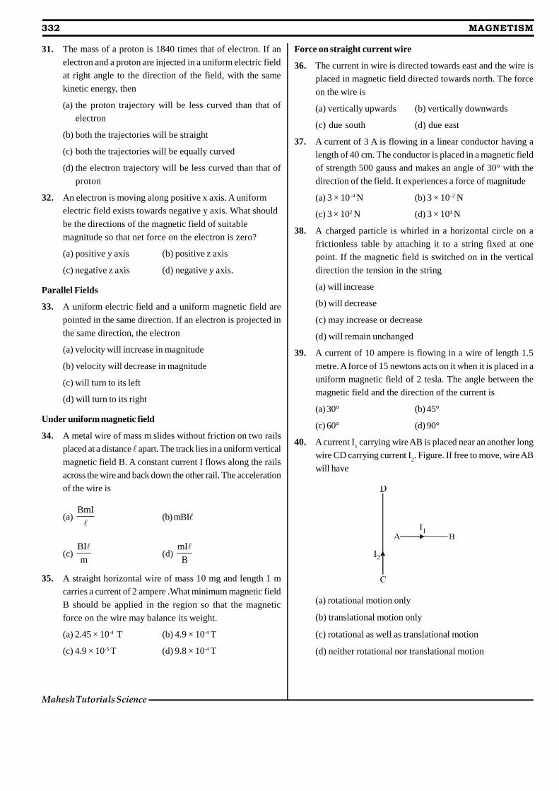
332 MAGNETISM
Mahesh Tutorials Science
31. The mass of a proton is 1840 times that of electron. If an
electron and a proton are injected in a uniform electric field
at right angle to the direction of the field, with the same
kinetic energy, then
(a) the proton trajectory will be less curved than that of
electron
(b) both the trajectories will be straight
(c) both the trajectories will be equally curved
(d) the electron trajectory will be less curved than that of
proton
32. An electron is moving along positive x axis. A uniform
electric field exists towards negative y axis. What should
be the directions of the magnetic field of suitable
magnitude so that net force on the electron is zero?
(a) positive y axis (b) positive z axis
(c) negative z axis (d) negative y axis.
Parallel Fields
33. A uniform electric field and a uniform magnetic field are
pointed in the same direction. If an electron is projected in
the same direction, the electron
(a) velocity will increase in magnitude
(b) velocity will decrease in magnitude
(c) will turn to its left
(d) will turn to its right
Under uniform magnetic field
34. A metal wire of mass m slides without friction on two rails
placed at a distance apart. The track lies in a uniform vertical
magnetic field B. A constant current I flows along the rails
across the wire and back down the other rail. The acceleration
of the wire is
(a)BmI
(b) mBI
(c)BI
m
(d)
mI
B
35. A straight horizontal wire of mass 10 mg and length 1 m
carries a current of 2 ampere .What minimum magnetic field
B should be applied in the region so that the magnetic
force on the wire may balance its weight.
(a) 2.45 × 10⁻⁴ T (b) 4.9 × 10⁻⁴ T
(c) 4.9 × 10⁻⁵ T (d) 9.8 × 10⁻⁴ T
Force on straight current wire
36. The current in wire is directed towards east and the wire is
placed in magnetic field directed towards north. The force
on the wire is
(a) vertically upwards (b) vertically downwards
(c) due south (d) due east
37. A current of 3 A is flowing in a linear conductor having a
length of 40 cm. The conductor is placed in a magnetic field
of strength 500 gauss and makes an angle of 30° with the
direction of the field. It experiences a force of magnitude
(a) 3 × 10⁻⁴ N (b) 3 × 10⁻² N
(c) 3 × 10² N (d) 3 × 10⁴ N
38. A charged particle is whirled in a horizontal circle on a
frictionless table by attaching it to a string fixed at one
point. If the magnetic field is switched on in the vertical
direction the tension in the string
(a) will increase
(b) will decrease
(c) may increase or decrease
(d) will remain unchanged
39. A current of 10 ampere is flowing in a wire of length 1.5
metre. A force of 15 newtons acts on it when it is placed in a
uniform magnetic field of 2 tesla. The angle between the
magnetic field and the direction of the current is
(a) 30° (b) 45°
(c) 60° (d) 90°
40. A current I1 carrying wire AB is placed near an another long
wire CD carrying current I2. Figure. If free to move, wire AB
will have
(a) rotational motion only
(b) translational motion only
(c) rotational as well as translational motion
(d) neither rotational nor translational motion
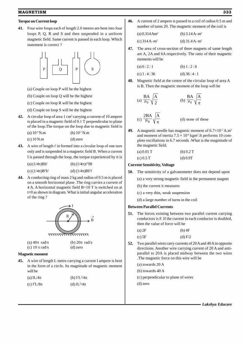
Lakshya Educare
MAGNETISM 333
Torque on Current loop
41. Four wire loops each of length 2.0 metres are bent into fourloops P, Q, R and S and then suspended in a uniformmagnetic field. Same current is passed in each loop. Whichstatement is correct ?
(a) Couple on loop P will be the highest
(b) Couple on loop Q will be the highest
(c) Couple on loop R will be the highest
(d) Couple on loop S will be the highest
42. A circular loop of area 1 cm2 carrying a current of 10 ampereis placed in a magnetic field of 0.1 T perpendicular to planeof the loop.The torque on the loop due to magnetic field is
(a) 10-4 N.m (b) 10-2 N.m
(c) 10 N.m (d) zero
43. A wire of length in formed into a circular loop of one turnonly and is suspended in a magnetic field B. When a currentI is passed through the loop, the torque experienced by it is
(a) (1/4)BI (b) (1/4)2IB
(c) (1/4)B2I (d) (1/4)BI2
44. A conducting ring of mass 2 kg and radius of 0.5 m is placedon a smooth horizontal plane .The ring carries a current of4 A. A horizontal magnetic field B=10 T is switched on att=0 as shown in diagram. What is initial angular accelerationof the ring ?
I
BR
(a) 40π rad/s (b) 20π rad/s(c) 10 π rad/s (d) zero
Magnetic moment
45. A wire of length L metre carrying a current I ampere is bentin the form of a circle. Its magnitude of magnetic momentwill be
(a) IL/4 (b) I2L2/4
(c) I2L/8 (d) IL2/4
46. A current of 2 ampere is passed in a coil of radius 0.5 m andnumber of turns 20. The magnetic moment of the coil is
(a) 0.314 Am2 (b) 3.14 A–m2
(c) 314 A–m2 (d) 31.4 A–m2
47. The area of cross-section of three magnets of same lengthare A, 2A and 6A respectively. The ratio of their magneticmoments will be
(a) 6 : 2 : 1 (b) 1 : 2 : 6
(c) 1 : 4 : 36 (d) 36 : 4 : 1
48. Magnetic field at the centre of the circular loop of area Ais B. Then the magnetic moment of the loop will be
(a)0
BA A
2 (b)0
BA A
(c)0
2BA A (d) none of these
49. A magnetic needle has magnetic moment of 6.7×10⁻² A.m2
and moment of inertia 7.5 × 10⁻⁶ kgm2.It performs 10 com-plete oscillations in 6.7 seconds .What is the magnitude ofthe magnetic field.
(a) 0.01 T (b) 0.2 T
(c) 0.5 T (d) 0.9T
Current Sensitivity, Voltage
50. The sensitivity of a galvanometer does not depend upon
(a) a very strong magnetic field in the permanent magnet
(b) the current it measures
(c) a very thin, weak suspension
(d) a large number of turns in the coil
Between Parallel Currents
51. The forces existing between two parallel current carryingconductors is F. If the current in each conductor is doubled,then the value of force will be
(a) 2F (b) 4F
(c) 5F (d) F/2
52. Two parallel wires carry currents of 20 A and 40 A in oppositedirections. Another wire carrying current of 20 A and anti-parallel to 20A is placed midway between the two wires.The magnetic force on this wire will be
(a) towards 20 A
(b) towards 40 A
(c) perpendicular to plane of wires
(d) zero
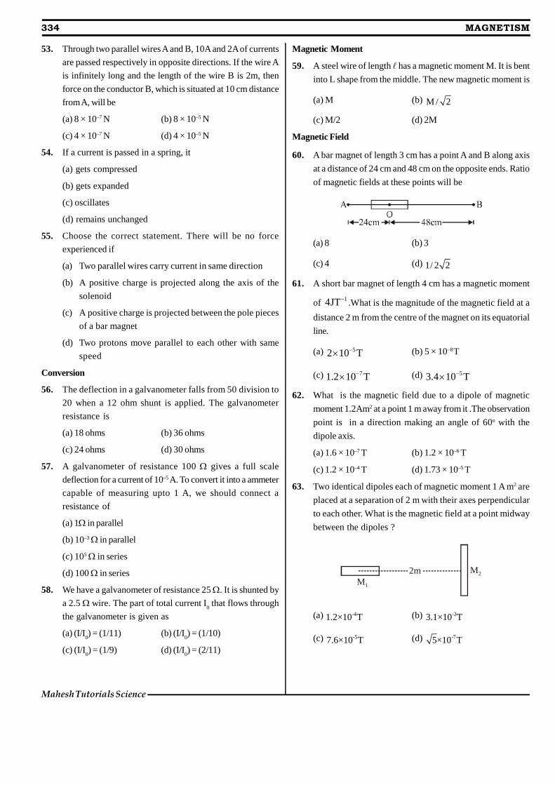
334 MAGNETISM
Mahesh Tutorials Science
53. Through two parallel wires A and B, 10A and 2A of currents
are passed respectively in opposite directions. If the wire A
is infinitely long and the length of the wire B is 2m, then
force on the conductor B, which is situated at 10 cm distance
from A, will be
(a) 8 × 10⁻⁷ N (b) 8 × 10⁻⁵ N
(c) 4 × 10⁻⁷ N (d) 4 × 10⁻⁵ N
54. If a current is passed in a spring, it
(a) gets compressed
(b) gets expanded
(c) oscillates
(d) remains unchanged
55. Choose the correct statement. There will be no force
experienced if
(a) Two parallel wires carry current in same direction
(b) A positive charge is projected along the axis of the
solenoid
(c) A positive charge is projected between the pole pieces
of a bar magnet
(d) Two protons move parallel to each other with same
speed
Conversion
56. The deflection in a galvanometer falls from 50 division to
20 when a 12 ohm shunt is applied. The galvanometer
resistance is
(a) 18 ohms (b) 36 ohms
(c) 24 ohms (d) 30 ohms
57. A galvanometer of resistance 100 gives a full scale
deflection for a current of 10–5 A. To convert it into a ammeter
capable of measuring upto 1 A, we should connect a
resistance of
(a) 1 in parallel
(b) 10–3 in parallel
(c) 105 in series
(d) 100 in series
58. We have a galvanometer of resistance 25. It is shunted by
a 2.5 wire. The part of total current I0 that flows through
the galvanometer is given as
(a) (I/I0) = (1/11) (b) (I/I
0) = (1/10)
(c) (I/I0) = (1/9) (d) (I/I
0) = (2/11)
Magnetic Moment
59. A steel wire of length has a magnetic moment M. It is bent
into L shape from the middle. The new magnetic moment is
(a) M (b) M / 2
(c) M/2 (d) 2M
Magnetic Field
60. A bar magnet of length 3 cm has a point A and B along axis
at a distance of 24 cm and 48 cm on the opposite ends. Ratio
of magnetic fields at these points will be
(a) 8 (b) 3
(c) 4 (d) 1/ 2 2
61. A short bar magnet of length 4 cm has a magnetic moment
of 14JT .What is the magnitude of the magnetic field at a
distance 2 m from the centre of the magnet on its equatorial
line.
(a) 52 10 T (b) 5 × 10⁻⁸T
(c) 71.2 10 T (d) 53.4 10 T
62. What is the magnetic field due to a dipole of magnetic
moment 1.2Am2 at a point 1 m away from it .The observation
point is in a direction making an angle of 60o with the
dipole axis.
(a) 1.6 × 10⁻⁷ T (b) 1.2 × 10⁻⁶ T
(c) 1.2 × 10⁻⁴ T (d) 1.73 × 10⁻⁵ T
63. Two identical dipoles each of magnetic moment 1 A m2 are
placed at a separation of 2 m with their axes perpendicular
to each other. What is the magnetic field at a point midway
between the dipoles ?
M1
M22m
(a) -41.2×10 T (b) -33.1×10 T
(c) -57.6×10 T (d) -75×10 T
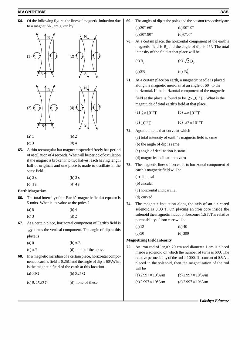
Lakshya Educare
MAGNETISM 335
64. Of the following figure, the lines of magnetic induction dueto a magnet SN, are given by
(1) (2)
(3) (4)
(a) 1 (b) 2
(c) 3 (d) 4
65. A thin rectangular bar magnet suspended freely has periodof oscillation of 4 seconds. What will be period of oscillationif the magnet is broken into two halves; each having lengthhalf of original; and one piece is made to oscillate in thesame field.
(a) 2 s (b) 3 s
(c) 1 s (d) 4 s
Earth Magnetism
66. The total intensity of the Earth’s magnetic field at equator is5 units. What is its value at the poles ?
(a) 5 (b) 4
(c) 3 (d) 2
67. At a certain place, horizontal component of Earth’s field is
3 times the vertical component. The angle of dip at this
place is
(a) 0 (b) /3
(c) /6 (d) none of the above
68. In a magnetic meridian of a certain place, horizontal compo-nent of earth’s field is 0.25G and the angle of dip is 60o.Whatis the magnetic field of the earth at this location.
(a) 0.5G (b) 0.25 G
(c) 0. 25 3G (d) none of these
69. The angles of dip at the poles and the equator respectively are
(a) 30°, 60° (b) 90°, 0°
(c) 30°, 90° (d) 0°, 0°
70. At a certain place, the horizontal component of the earth’smagnetic field is B
0 and the angle of dip is 45°. The total
intensity of the field at that place will be
(a) B0
(b) 02 B
(c) 2B0
(d) 20B
71. At a certain place on earth, a magnetic needle is placedalong the magnetic meridian at an angle of 60° to thehorizontal. If the horizontal component of the magnetic
field at the place is found to be 52 10 T . What is the
magnitude of total earth’s field at that place.
(a) 42 10 T (b) 54 10 T
(c) 510 T (d) 53 10 T
72. Agonic line is that curve at which
(a) total intensity of earth ‘s magnetic field is same
(b) the angle of dip is same
(c) angle of declination is same
(d) magnetic declination is zero
73. The magnetic lines of force due to horizontal component ofearth’s magnetic field will be
(a) elliptical
(b) circular
(c) horizontal and parallel
(d) curved
74. The magnetic induction along the axis of an air coredsolenoid is 0.03 T. On placing an iron core inside thesolenoid the magnetic induction becomes 1.5T .The relativepermeability of iron core will be
(a) 12 (b) 40
(c) 50 (d) 300
Magnetizing Field Intensity
75. An iron rod of length 20 cm and diameter 1 cm is placedinside a solenoid on which the number of turns is 600. Therelative permeability of the rod is 1000. If a current of 0.5 A isplaced in the solenoid, then the magnetisation of the rodwill be
(a) 2.997 × 10² A/m (b) 2.997 × 10³ A/m
(c) 2.997 × 10⁴ A/m (d) 2.997 × 10⁵ A/m
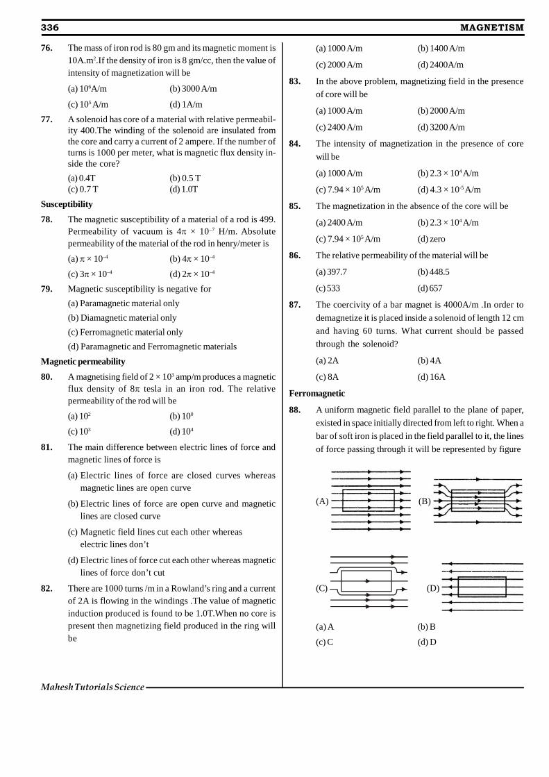
76. The mass of iron rod is 80 gm and its magnetic moment is10A.m2.If the density of iron is 8 gm/cc, then the value ofintensity of magnetization will be
(a) 106A/m (b) 3000 A/m
(c) 105 A/m (d) 1A/m
77. A solenoid has core of a material with relative permeabil-ity 400.The winding of the solenoid are insulated fromthe core and carry a current of 2 ampere. If the number ofturns is 1000 per meter, what is magnetic flux density in-side the core?
(a) 0.4T (b) 0.5 T(c) 0.7 T (d) 1.0T
Susceptibility
78. The magnetic susceptibility of a material of a rod is 499.Permeability of vacuum is 4 × 10⁻⁷ H/m. Absolutepermeability of the material of the rod in henry/meter is
(a) × 10–4 (b) 4 × 10⁻⁴
(c) 3 × 10⁻⁴ (d) 2 × 10⁻⁴
79. Magnetic susceptibility is negative for
(a) Paramagnetic material only
(b) Diamagnetic material only
(c) Ferromagnetic material only
(d) Paramagnetic and Ferromagnetic materials
Magnetic permeability
80. A magnetising field of 2 × 10³ amp/m produces a magneticflux density of 8 tesla in an iron rod. The relativepermeability of the rod will be
(a) 102 (b) 100
(c) 103 (d) 104
81. The main difference between electric lines of force andmagnetic lines of force is
(a) Electric lines of force are closed curves whereasmagnetic lines are open curve
(b) Electric lines of force are open curve and magneticlines are closed curve
(c) Magnetic field lines cut each other whereaselectric lines don’t
(d) Electric lines of force cut each other whereas magneticlines of force don’t cut
82. There are 1000 turns /m in a Rowland’s ring and a currentof 2A is flowing in the windings .The value of magneticinduction produced is found to be 1.0T.When no core ispresent then magnetizing field produced in the ring willbe
(a) 1000 A/m (b) 1400 A/m
(c) 2000 A/m (d) 2400A/m
83. In the above problem, magnetizing field in the presence
of core will be
(a) 1000 A/m (b) 2000 A/m
(c) 2400 A/m (d) 3200 A/m
84. The intensity of magnetization in the presence of core
will be
(a) 1000 A/m (b) 2.3 × 10⁴ A/m
(c) 7.94 × 10⁵ A/m (d) 4.3 × 10⁻⁵ A/m
85. The magnetization in the absence of the core will be
(a) 2400 A/m (b) 2.3 × 10⁴ A/m
(c) 7.94 × 10⁵ A/m (d) zero
86. The relative permeability of the material will be
(a) 397.7 (b) 448.5
(c) 533 (d) 657
87. The coercivity of a bar magnet is 4000A/m .In order to
demagnetize it is placed inside a solenoid of length 12 cm
and having 60 turns. What current should be passed
through the solenoid?
(a) 2A (b) 4A
(c) 8A (d) 16A
Ferromagnetic
88. A uniform magnetic field parallel to the plane of paper,
existed in space initially directed from left to right. When a
bar of soft iron is placed in the field parallel to it, the lines
of force passing through it will be represented by figure
(A) (B)
(C) (D)
(a) A (b) B
(c) C (d) D
336 MAGNETISM
Mahesh Tutorials Science
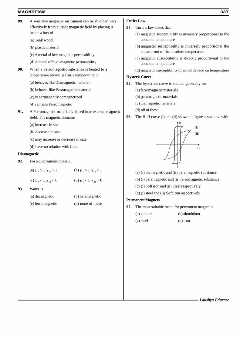
89. A sensitive magnetic instrument can be shielded very
effectively from outside magnetic field by placing it
inside a box of
(a) Teak wood
(b) plastic material
(c) A metal of low magnetic permeability
(d) A metal of high magnetic permeability
90. When a Ferromagnetic substance is heated to a
temperature above its Curie temperature it
(a) behaves like Diamagnetic material
(b) behaves like Paramagnetic material
(c) is permanently demagnetized
(d) remains Ferromagnetic
91. A Ferromagnetic material is placed in an external magnetic
field. The magnetic domains
(a) increase in size
(b) decrease in size
(c) may increase or decrease in size
(d) have no relation with field
Diamagnetic
92. For a diamagnetic material
(a) r m1, 1 (b) r m1, 1
(c) r m1, 0 (d) r m1, 0
93. Water is
(a) diamagnetic (b) paramagnetic
(c) ferromagnetic (d) none of these
Curies Law
94. Curie’s law states that(a) magnetic susceptibility is inversely proportional to the
absolute temperature
(b) magnetic susceptibility is inversely proportional thesquare root of the absolute temperature
(c) magnetic susceptibility is directly proportional to theabsolute temperature
(d) magnetic susceptibility does not depend on temperature
Hysteris Curve
95. The hysterisis curve is studied generally for
(a) ferromagnetic materials
(b) paramagnetic materials
(c) diamagnetic materials
(d) all of these
96. The B–H curve (i) and (ii) shown in figure associated with
(a) (i) diamagnetic and (ii) paramagnetic substance
(b) (i) paramagnetic and (ii) ferromagnetic substance
(c) (i) Soft iron and (ii) Steel respectively
(d) (i) steel and (ii) Soft iron respectively
Permanent Magnets
97. The most suitable metal for permanent magnet is
(a) copper (b) aluminium
(c) steel (d) iron
Lakshya Educare
MAGNETISM 337
EXERCISE - 2 : PREVIOUS YEAR COMPETITION QUESTIONS
PREVIOUSYEARSAFMC QUESTIONS
1. A current carrying wire in the neighbourhood produces
(AFMC 1999)
(a) electric and magnetic fields
(b) magnetic field only
(c) no field
(d) electric field
2. Two parallel wires in free space are 10 cm apart and each
carries a current of 10A in the same direction. The force
exerted by one wire on other per metre of length of the
wire is (AFMC 1999)
(a) 2 × 10⁻⁶ N (b) 2 × 10⁻⁴ N
(c) 2 × 10⁻³ N (d) 2 × 10⁻² N
3. A long hollow copper pipe carries a current, then magnetic
field produced is (AFMC 1999)
(a) both inside and outside the pipe
(b) neither inside nor outside the pipe
(c) outside the pipe only
(d) inside the pipe only
4. A coil having 100 turns and area of 0.001 m2 is free to
rotate about an axis, the coil is placed perpendicular to a
magnetic field of 1.0 Wb/m2. If the coil is rotated rapidly
through an angle of 180°, how much charge will flow
through the coil ? The resistance of the coil is 10.
(AFMC 2002)
(a) 0.02 C (b) 0.04 C
(c) 0.08 C (d) 0.01 C
5. Wb/m2 is equal to (AFMC 2001)
(a) dyne (b) tesla
(c) watt (d) henry
6. Two wires carry current in different directions. They will
(AFMC 2003)
(a) attract each other
(b) repel each other
(c) create gravitational field
(d) any of the above
7. Which one is a vector quantity ? (AFMC 2003)
(a) Time (b) Temperature
(c) Flux density (d) Magnetic field intensity
8. A wire carrying current I and other carrying 2 I in the samedirection produce a magnetic field B at the mid-point. Whatwill be the field when 2 I wire is switched off ?
(a) B/2 (b) 2B (AFMC 2005)
(c) B (d) 4B
9. When a charged particle moving with velocity v is
subjected to a magnetic feild of induction B
, the force onit is non-zero. This implies that (AFMC 2006)
(a) angle between v and B
is necessarily 90°
(b) angle between v and B
can have any value otherthan 90°
(c) angle between v
and B
can have any value otherthan zero and 180°
(d) angle between v
and B
is either zero or 180°
10. The path of an electron in a uniform magnetic field may be
(a) circular but not helical (AFMC 2007)
(b) helical but not circular
(c) neither helical nor circular
(d) either helical or circular
11. A straight wire of mass 200 g and length 1.5 m carries acurrent of 2 A. It is suspended in mid-air by a uniformhorizontal magnetic field B. The magnitude of B (in tesla)is (assume g = 9.8 ms–2) (AFMC 2008)
(a) 2 (b) 1.5
(c) 0.55 (d) 0.65
12. A wire PQR is bent as shown in fig.and is placed in a regionof uniform magnetic field B. The length of PQ = QR = l. Acurrent I ampere flows through the wire as shown. Themagnitude of the force on PQ and QR will be
(AFMC 2008)
B
R
I
QIP
(a) BIl, 0 (b) 2BIl, 0
(c) 0, BIl (d) 0, 0
338 MAGNETISM
Mahesh Tutorials Science
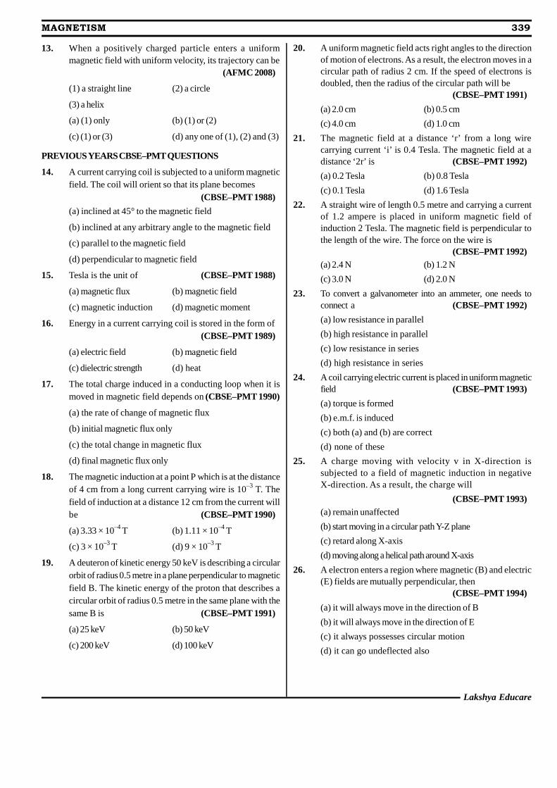
13. When a positively charged particle enters a uniformmagnetic field with uniform velocity, its trajectory can be
(AFMC 2008)
(1) a straight line (2) a circle
(3) a helix
(a) (1) only (b) (1) or (2)
(c) (1) or (3) (d) any one of (1), (2) and (3)
PREVIOUS YEARS CBSE–PMT QUESTIONS
14. A current carrying coil is subjected to a uniform magneticfield. The coil will orient so that its plane becomes
(CBSE–PMT 1988)(a) inclined at 45° to the magnetic field
(b) inclined at any arbitrary angle to the magnetic field
(c) parallel to the magnetic field
(d) perpendicular to magnetic field
15. Tesla is the unit of (CBSE–PMT 1988)
(a) magnetic flux (b) magnetic field
(c) magnetic induction (d) magnetic moment
16. Energy in a current carrying coil is stored in the form of(CBSE–PMT 1989)
(a) electric field (b) magnetic field
(c) dielectric strength (d) heat
17. The total charge induced in a conducting loop when it ismoved in magnetic field depends on (CBSE–PMT 1990)
(a) the rate of change of magnetic flux
(b) initial magnetic flux only
(c) the total change in magnetic flux
(d) final magnetic flux only
18. The magnetic induction at a point P which is at the distanceof 4 cm from a long current carrying wire is 10–3 T. Thefield of induction at a distance 12 cm from the current willbe (CBSE–PMT 1990)
(a) 3.33 × 10⁻⁴ T (b) 1.11 × 10⁻⁴ T
(c) 3 × 10⁻³ T (d) 9 × 10⁻³ T
19. A deuteron of kinetic energy 50 keV is describing a circularorbit of radius 0.5 metre in a plane perpendicular to magneticfield B. The kinetic energy of the proton that describes acircular orbit of radius 0.5 metre in the same plane with thesame B is (CBSE–PMT 1991)
(a) 25 keV (b) 50 keV
(c) 200 keV (d) 100 keV
20. A uniform magnetic field acts right angles to the directionof motion of electrons. As a result, the electron moves in acircular path of radius 2 cm. If the speed of electrons isdoubled, then the radius of the circular path will be
(CBSE–PMT 1991)(a) 2.0 cm (b) 0.5 cm
(c) 4.0 cm (d) 1.0 cm
21. The magnetic field at a distance ‘r’ from a long wirecarrying current ‘i’ is 0.4 Tesla. The magnetic field at adistance ‘2r’ is (CBSE–PMT 1992)(a) 0.2 Tesla (b) 0.8 Tesla
(c) 0.1 Tesla (d) 1.6 Tesla
22. A straight wire of length 0.5 metre and carrying a currentof 1.2 ampere is placed in uniform magnetic field ofinduction 2 Tesla. The magnetic field is perpendicular tothe length of the wire. The force on the wire is
(CBSE–PMT 1992)(a) 2.4 N (b) 1.2 N
(c) 3.0 N (d) 2.0 N
23. To convert a galvanometer into an ammeter, one needs toconnect a (CBSE–PMT 1992)(a) low resistance in parallel
(b) high resistance in parallel
(c) low resistance in series
(d) high resistance in series
24. A coil carrying electric current is placed in uniform magneticfield (CBSE–PMT 1993)(a) torque is formed
(b) e.m.f. is induced
(c) both (a) and (b) are correct
(d) none of these
25. A charge moving with velocity v in X-direction issubjected to a field of magnetic induction in negativeX-direction. As a result, the charge will
(CBSE–PMT 1993)(a) remain unaffected
(b) start moving in a circular path Y-Z plane
(c) retard along X-axis
(d) moving along a helical path around X-axis
26. A electron enters a region where magnetic (B) and electric(E) fields are mutually perpendicular, then
(CBSE–PMT 1994)(a) it will always move in the direction of B
(b) it will always move in the direction of E
(c) it always possesses circular motion
(d) it can go undeflected also
Lakshya Educare
MAGNETISM 339

340 MAGNETISM
Mahesh Tutorials Science
27. A straight wire of diameter 0.5 mm carrying a current of 1Ais replaced by another wire of 1mm diameter carrying samecurrent. The strength of magnetic field far away is
(CBSE–PMT 1995)(a) twice the earlier value
(b) same as the earlier value
(c) one-half of the earlier value
(d) one-quarter of the earlier value
28. At what distance from a long straight wire carrying acurrent of 12A will the magnetic field be equal to 3 × 10⁻⁶
Wb/m2 ? (CBSE–PMT 1995)(a) 8 × 10⁻¹ m (b) 12 × 10–2 m
(c) 18 × 10–2 m (d) 24 × 10–2 m
29. The magnetic field (dB) due to a small element (dl) at a
distance ( r
) and element carrying current i is(CBSE–PMT 1996)
(a) 0 dl rdB i
4 r
(b) 20
2
dl rdB i
4 r
(c) 20 dl rdB i
4 r
(d) 0
3
dl rdB i
4 r
30. A 10eV electron is circulating in a plane at right anglesto a uniform field at magnetic induction 10–4 Wb/m2
(= 1.0 gauss). The orbital radius of the electron is(CBSE–PMT 1996)
(a) 12 cm (b) 16 cm
(c) 2
8 2
cm (d) 18 cm
31. Two parallel wires in free space are 10 cm apart, and eachcarries a current of 10A, in the same direction. The force,one wire exerts on the other, per metre of length, is
(CBSE–PMT 1997)(a) 2 × 10⁻⁷ N, repulsive (b) 2 × 10⁻⁷ N, attractive
(c) 2 × 10⁻⁴ N, repulsive (d) 2 × 10⁻⁴ N, attractive
32. For protecting a sensitive equipment from the externalmagnetic field, it should be (CBSE–PMT 1998)(a) placed inside an aluminium can
(b) placed inside an iron can
(c) wrapped with insulation around it when passing currentthrough it
(d) surrounded with fine copper sheet
33. If a long hollow copper pipe carries a current, thenmagnetic field is produced (CBSE–PMT 1999)(a) inside the pipe only (b) outside the pipe only
(c) both inside and outside the pipe
(d) no where
34. A straight wire of diameter 0.5 mm carrying a current of 1Ais replaced by another wire of diameter 1 mm carrying thesame current. The strength of magnetic field far away is
(CBSE–PMT 1999)(a) twice the earlier value
(b) one-half of the earlier value
(c) one quarter of the earlier value
(d) same as earlier value
35. Magnetic field due to 0.1A current flowing through acircular coil of radius 0.1m and 1000 turns at the centre ofthe coil is (CBSE–PMT 1999)(a) 0.2 T (b) 2 × 10⁻⁴ T
(c) 4.9 × 10⁻⁸ T (d) 9.8 × 10⁻⁴ T
36. An electron moves with a velocity 1 × 10³ m/s in a magneticfield of induction 0.3 T at an angle 30°. If e/m of electron is1.76 × 1011 C/kg, the radius of the path is nearly
(CBSE–PMT 2000)(a) 10–8 m (b) 2 × 10⁻⁸ m
(c) 10–6 m (d) 10–10 m
37. Current is flowing in a coil of area A and number of turnsN, then magnetic moment of the coil M is equal to
(CBSE–PMT 2001)(a) NiA (b) Ni/A
(c) Ni / A (d) N2Ai
38. A charged particle of charge q and mass m enters
perpendicularly in a magnetic field B
. Kinetic energy ofthe particle is E; then frequency of rotation is
(CBSE–PMT 2001)
(a)qB
m(b)
qB
2 m
(c)qBE
2 m(d)
qB
2 E
39. The magnetic field of a given length of wire carrying acurrent for a single turn circular coil at centre is B, then itsvalue for two turns for the same wire when same currentpassing through it is (CBSE–PMT 2002)(a) B/4 (b) B/2
(c) 2B (d) 4B
40. A charge q moves in a region where electric field E
and
magnetic field B
both exist, then the force on it is(CBSE–PMT 2002)
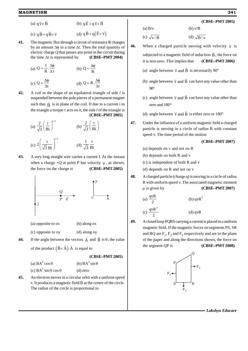
Lakshya Educare
MAGNETISM 341
(a) q v B
(b) q E q v B
(c) q B q B v
(d) q B q E v
41. The magnetic flux through a circuit of resistance R changesby an amount in a time t. Then the total quantity ofelectric charge Q that passes any point in the circuit duringthe time t is represented by (CBSE–PMT 2004)
(a)1
Q .R t
(b) Q
R
(c) Qt
(d) Q R .t
42. A coil in the shape of an equilateral triangle of side l issuspended between the pole pieces of a permanent magnet
such that B
is in plane of the coil. If due to a current i in
the triangle a torque acts on it, the side l of the triangle is(CBSE–PMT 2005)
(a)1/ 2
2
Bi3
(b)2
Bi3
(c)
1/ 2
23 Bi
(d)1
Bi3
43. A very long straight wire carries a current I. At the instant
when a charge +Q at point P has velocity v , as shown,
the force on the charge is (CBSE–PMT 2005)
(a) opposite to ox (b) along ox
(c) opposite to oy (d) along oy
44. If the angle between the vectors A
and B
is , the value
of the product B A .A
is equal to
(CBSE–PMT 2005)
(a) BA2 cos (b) BA2 sin
(c) BA2 sin cos (d) zero
45. An electron moves in a circular orbit with a uniform speedv. It produces a magnetic field B at the centre of the circle.The radius of the circle is proportional to
(CBSE–PMT 2005)(a) B/v (b) v/B
(c) v / B (d) B / v
46. When a charged particle moving with velocity v is
subjected to a magnetic field of induction B
, the force on
it is non-zero. This implies that (CBSE–PMT 2006)
(a) angle between v and B
is necessarily 90°
(b) angle between v and B
can have any value other than
90°
(c) angle between v and B
can have any value other than
zero and 180°
(d) angle between v and B
is either zero or 180°
47. Under the influence of a uniform magnetic field a charged
particle is moving in a circle of radius R with constant
speed v. The time period of the motion
(CBSE–PMT 2007)
(a) depends on v and not on R
(b) depends on both R and v
(c) is independent of both R and v
(d) depends on R and not on v
48. A charged particle (charge q) is moving in a circle of radius
R with uniform speed v. The associated magnetic moment
is given by (CBSE–PMT 2007)
(a)qvR
2(b) qvR2
(c)2qvR
2(d) qvR
49. A closed loop PQRS carrying a current is placed in a uniform
magnetic field. If the magnetic forces on segments PS, SR
and RQ are F1, F2 and F3 respectively and are in the plane
of the paper and along the directions shown, the force on
the segment QP is (CBSE–PMT 2008)
P
Q
RS
F3
F2
F1
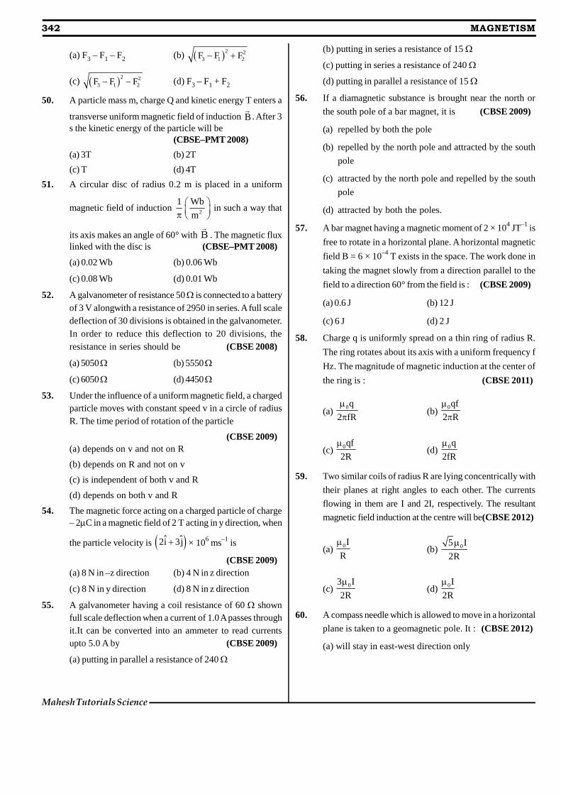
342 MAGNETISM
Mahesh Tutorials Science
(a) F3 – F1 – F2 (b) 2 23 1 2F F F
(c) 2 23 1 2F F F (d) F3 – F1 + F2
50. A particle mass m, charge Q and kinetic energy T enters a
transverse uniform magnetic field of induction B
. After 3s the kinetic energy of the particle will be
(CBSE–PMT 2008)(a) 3T (b) 2T
(c) T (d) 4T
51. A circular disc of radius 0.2 m is placed in a uniform
magnetic field of induction 2
1 Wb
m
in such a way that
its axis makes an angle of 60° with B
. The magnetic fluxlinked with the disc is (CBSE–PMT 2008)
(a) 0.02 Wb (b) 0.06 Wb
(c) 0.08 Wb (d) 0.01 Wb
52. A galvanometer of resistance 50 is connected to a batteryof 3 V alongwith a resistance of 2950 in series. A full scaledeflection of 30 divisions is obtained in the galvanometer.In order to reduce this deflection to 20 divisions, theresistance in series should be (CBSE 2008)
(a) 5050 (b) 5550
(c) 6050 (d) 4450
53. Under the influence of a uniform magnetic field, a chargedparticle moves with constant speed v in a circle of radiusR. The time period of rotation of the particle
(CBSE 2009)(a) depends on v and not on R
(b) depends on R and not on v
(c) is independent of both v and R
(d) depends on both v and R
54. The magnetic force acting on a charged particle of charge– 2C in a magnetic field of 2 T acting in y direction, when
the particle velocity is ˆ ˆ2i 3j × 106 ms–1 is
(CBSE 2009)(a) 8 N in –z direction (b) 4 N in z direction
(c) 8 N in y direction (d) 8 N in z direction
55. A galvanometer having a coil resistance of 60 shownfull scale deflection when a current of 1.0 A passes throughit.It can be converted into an ammeter to read currentsupto 5.0 A by (CBSE 2009)
(a) putting in parallel a resistance of 240
(b) putting in series a resistance of 15
(c) putting in series a resistance of 240
(d) putting in parallel a resistance of 15
56. If a diamagnetic substance is brought near the north or
the south pole of a bar magnet, it is (CBSE 2009)
(a) repelled by both the pole
(b) repelled by the north pole and attracted by the south
pole
(c) attracted by the north pole and repelled by the south
pole
(d) attracted by both the poles.
57. A bar magnet having a magnetic moment of 2 × 10⁴ JT–1 is
free to rotate in a horizontal plane. A horizontal magnetic
field B = 6 × 10⁻⁴ T exists in the space. The work done in
taking the magnet slowly from a direction parallel to the
field to a direction 60° from the field is : (CBSE 2009)
(a) 0.6 J (b) 12 J
(c) 6 J (d) 2 J
58. Charge q is uniformly spread on a thin ring of radius R.
The ring rotates about its axis with a uniform frequency f
Hz. The magnitude of magnetic induction at the center of
the ring is : (CBSE 2011)
(a)0q
2 fR
(b)0qf
2 R
(c) 0qf
2R
(d) 0q
2fR
59. Two similar coils of radius R are lying concentrically with
their planes at right angles to each other. The currents
flowing in them are I and 2I, respectively. The resultant
magnetic field induction at the centre will be(CBSE 2012)
(a) 0I
R
(b) 05 I
2R
(c) 03 I
2R
(d) 0I
2R
60. A compass needle which is allowed to move in a horizontal
plane is taken to a geomagnetic pole. It : (CBSE 2012)
(a) will stay in east-west direction only
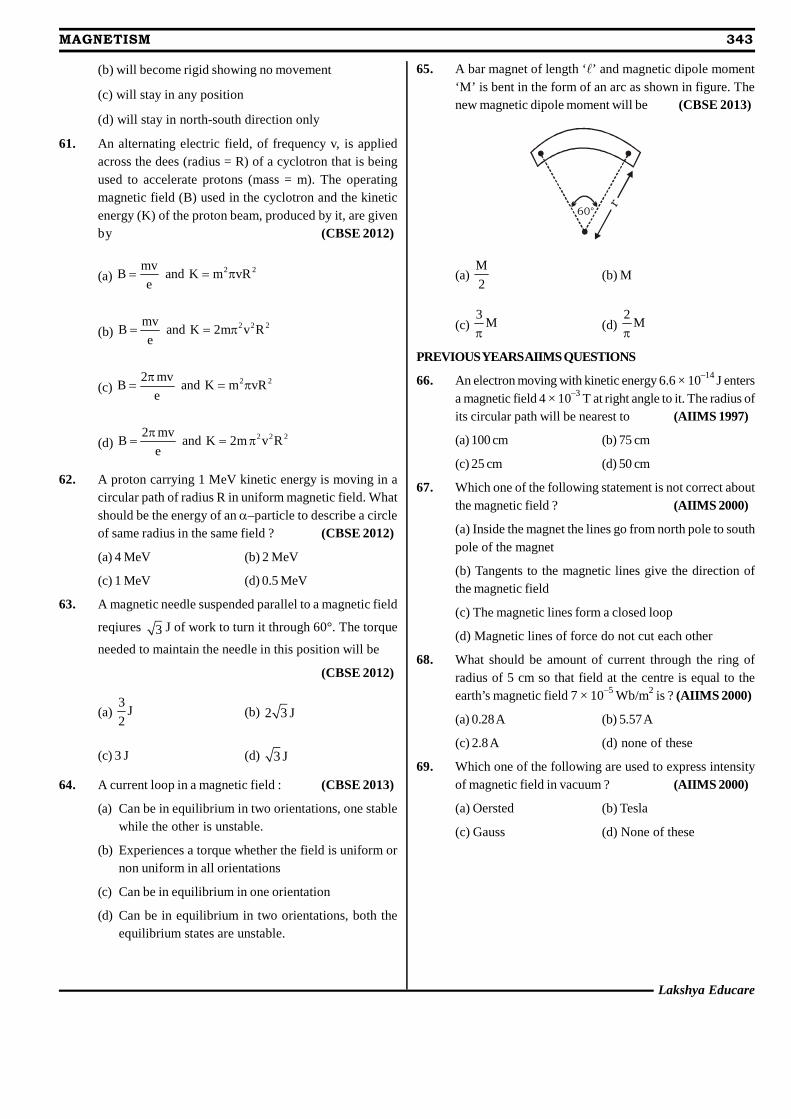
Lakshya Educare
MAGNETISM 343
(b) will become rigid showing no movement
(c) will stay in any position
(d) will stay in north-south direction only
61. An alternating electric field, of frequency v, is appliedacross the dees (radius = R) of a cyclotron that is beingused to accelerate protons (mass = m). The operatingmagnetic field (B) used in the cyclotron and the kineticenergy (K) of the proton beam, produced by it, are givenby (CBSE 2012)
(a)2 2mv
B and K m vRe
(b)2 2 2mv
B and K 2m v Re
(c)2 22 mv
B and K m vRe
(d)2 2 22 mv
B and K 2m v Re
62. A proton carrying 1 MeV kinetic energy is moving in acircular path of radius R in uniform magnetic field. Whatshould be the energy of an –particle to describe a circleof same radius in the same field ? (CBSE 2012)
(a) 4 MeV (b) 2 MeV
(c) 1 MeV (d) 0.5 MeV
63. A magnetic needle suspended parallel to a magnetic field
reqiures 3 J of work to turn it through 60°. The torque
needed to maintain the needle in this position will be
(CBSE 2012)
(a)3
J2
(b) 2 3 J
(c) 3 J (d) 3 J
64. A current loop in a magnetic field : (CBSE 2013)
(a) Can be in equilibrium in two orientations, one stablewhile the other is unstable.
(b) Experiences a torque whether the field is uniform ornon uniform in all orientations
(c) Can be in equilibrium in one orientation
(d) Can be in equilibrium in two orientations, both theequilibrium states are unstable.
65. A bar magnet of length ‘’ and magnetic dipole moment‘M’ is bent in the form of an arc as shown in figure. Thenew magnetic dipole moment will be (CBSE 2013)
60°
r
(a)M
2(b) M
(c)3
M
(d)2
M
PREVIOUSYEARSAIIMS QUESTIONS
66. An electron moving with kinetic energy 6.6 × 10⁻¹⁴ J entersa magnetic field 4 × 10⁻³ T at right angle to it. The radius ofits circular path will be nearest to (AIIMS 1997)
(a) 100 cm (b) 75 cm
(c) 25 cm (d) 50 cm
67. Which one of the following statement is not correct aboutthe magnetic field ? (AIIMS 2000)
(a) Inside the magnet the lines go from north pole to southpole of the magnet
(b) Tangents to the magnetic lines give the direction ofthe magnetic field
(c) The magnetic lines form a closed loop
(d) Magnetic lines of force do not cut each other
68. What should be amount of current through the ring ofradius of 5 cm so that field at the centre is equal to theearth’s magnetic field 7 × 10⁻⁵ Wb/m2 is ? (AIIMS 2000)
(a) 0.28 A (b) 5.57 A
(c) 2.8 A (d) none of these
69. Which one of the following are used to express intensityof magnetic field in vacuum ? (AIIMS 2000)
(a) Oersted (b) Tesla
(c) Gauss (d) None of these
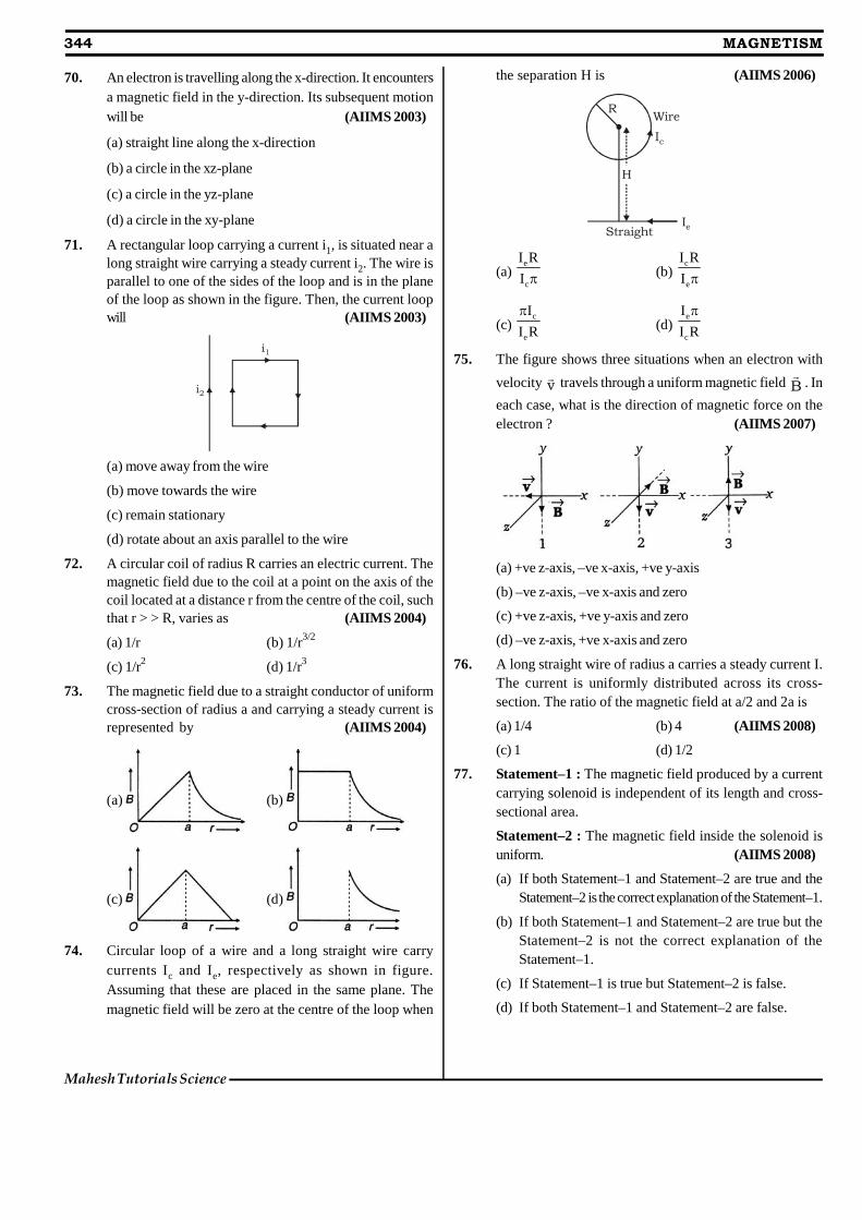
70. An electron is travelling along the x-direction. It encountersa magnetic field in the y-direction. Its subsequent motionwill be (AIIMS 2003)
(a) straight line along the x-direction
(b) a circle in the xz-plane
(c) a circle in the yz-plane
(d) a circle in the xy-plane
71. A rectangular loop carrying a current i1, is situated near along straight wire carrying a steady current i2. The wire isparallel to one of the sides of the loop and is in the planeof the loop as shown in the figure. Then, the current loopwill (AIIMS 2003)
i1
i2
(a) move away from the wire
(b) move towards the wire
(c) remain stationary
(d) rotate about an axis parallel to the wire
72. A circular coil of radius R carries an electric current. Themagnetic field due to the coil at a point on the axis of thecoil located at a distance r from the centre of the coil, suchthat r > > R, varies as (AIIMS 2004)
(a) 1/r (b) 1/r3/2
(c) 1/r2 (d) 1/r3
73. The magnetic field due to a straight conductor of uniformcross-section of radius a and carrying a steady current isrepresented by (AIIMS 2004)
(a) (b)
(c) (d)
74. Circular loop of a wire and a long straight wire carrycurrents Ic and Ie, respectively as shown in figure.Assuming that these are placed in the same plane. Themagnetic field will be zero at the centre of the loop when
the separation H is (AIIMS 2006)
R
IeStraight
H
Wire
Ic
(a)e
c
I R
I (b)c
e
I R
I
(c)c
e
I
I R
(d)
e
c
I
I R
75. The figure shows three situations when an electron with
velocity v travels through a uniform magnetic field B
. In
each case, what is the direction of magnetic force on theelectron ? (AIIMS 2007)
(a) +ve z-axis, –ve x-axis, +ve y-axis
(b) –ve z-axis, –ve x-axis and zero
(c) +ve z-axis, +ve y-axis and zero
(d) –ve z-axis, +ve x-axis and zero
76. A long straight wire of radius a carries a steady current I.The current is uniformly distributed across its cross-section. The ratio of the magnetic field at a/2 and 2a is
(a) 1/4 (b) 4 (AIIMS 2008)
(c) 1 (d) 1/2
77. Statement–1 : The magnetic field produced by a currentcarrying solenoid is independent of its length and cross-sectional area.
Statement–2 : The magnetic field inside the solenoid isuniform. (AIIMS 2008)
(a) If both Statement–1 and Statement–2 are true and theStatement–2 is the correct explanation of the Statement–1.
(b) If both Statement–1 and Statement–2 are true but theStatement–2 is not the correct explanation of theStatement–1.
(c) If Statement–1 is true but Statement–2 is false.
(d) If both Statement–1 and Statement–2 are false.
344 MAGNETISM
Mahesh Tutorials Science
78. If M be the mass of the charged particle, which enters withvelocity v normal to the magnetic field B, it will revolvewith angular speed given by ? (AIIMS 1996)
(a)0
B
q M (b) 0q B
M
(c) 0q M
B(d) q0BM
Lakshya Educare
MAGNETISM 345

ANSWER KEY
EXERCISE - 1 : BASIC OBJECTIVE QUESTIONS
1. (d) 2. (b) 3. (d) 4. (d) 5. (b) 6. (c) 7. (a) 8. (a) 9. (a) 10. (a)11. (a) 12. (c) 13. (b) 14. (d) 15. (b) 16. (a) 17. (d) 18. (d) 19. (b) 20. (b)21. (c) 22. (b) 23. (b) 24. (d) 25. (a) 26. (c) 27. (b) 28. (b) 29. (b) 30. (b)31. (c) 32. (c) 33. (b) 34. (c) 35. (c) 36. (a) 37. (b) 38. (c) 39. (a) 40. (c)41. (d) 42. (d) 43. (b) 44. (a) 45. (d) 46. (d) 47. (b) 48. (c) 49. (a) 50. (b)51. (b) 52. (b) 53. (b) 54. (a) 55. (b) 56. (a) 57. (b) 58. (a) 59. (b) 60. (a)61. (b) 62. (a) 63. (d) 64. (a) 65. (a) 66. (a) 67. (c) 68. (a) 69. (b) 70. (b)71. (b) 72. (d) 73. (c) 74. (c) 75. (d) 76. (a) 77. (d) 78. (d) 79. (b) 80. (d)81. (b) 82. (c) 83. (b) 84. (c) 85. (d) 86. (a) 87. (c) 88. (b) 89. (d) 90. (b)91. (c) 92. (c) 93. (a) 94. (a) 95. (a) 96. (c) 97. (c)
EXERCISE - 2 : PREVIOUS YEAR COMPETITION QUESTIONS
1. (b) 2. (b) 3. (c) 4. (a) 5. (b) 6. (b) 7. (d) 8. (c) 9. (c) 10. (d)11. (d) 12. (c) 13. (d) 14. (c) 15. (b) 16. (b) 17. (c) 18. (a) 19. (d) 20. (c)21. (a) 22. (b) 23. (a) 24. (a) 25. (a) 26. (d) 27. (b) 28. (a) 29. (d) 30. (c)31. (d) 32. (b) 33. (b) 34. (d) 35. (c) 36. (a) 37. (a) 38. (b) 39. (d) 40. (b)41. (b) 42. (c) 43. (d) 44. (d) 45. (c) 46. (c) 47. (c) 48. (a) 49. (b) 50. (c)51. (a) 52. (d) 53. (c) 54. (a) 55. (d) 56. (a) 57. (c) 58. (c) 59. (b) 60. (b)61. (d) 62. (c) 63. (c) 64. (a) 65. (c) 66. (d) 67. (a) 68. (b) 69. (a) 70. (b)71. (b) 72. (d) 73. (a) 74. (a) 75. (b) 76. (c) 77. (b) 78. (b)
Dream on !!
346 MAGNETISM
Mahesh Tutorials Science
Related Documents