Physics 178/278 - David Kleinfeld - Winter 2014 9 Dendritic Integration Dendrites are very long in terms of the electronic decay length. We thus might consider how dendrites compensate for the loss. One way is to generate spikes in the dendrites as a means of faithfully communicating dendritic signals from the distal ends. These issues were first addressed in hippocampal neurons by Spenser and Kandel back in 1961, whose data was consistent with dendritic spiking. While it has been known for quite some time that the dendrites of DRG cells produce spikes, a good twenty years went by until dendritic spiking was directly observed in neurons local to the mammalian brain. FIGURE - sackmann.eps The recent work on hippocampal cells shows that these spikes can substantially lower the threshold for distal input to affect spiking. The Hausser and Schiller groups have provided much of this data. FIGURE - hausser.eps Another way is to increase the strength of the synaptic input as one get’s further away from the soma. For modest losses, this is seen in the data of Magee. FIGURES - magee.eps However, as we see the signal still decays with distance from the soma even though there is a tendency for distal synapses to have higher currents. This drop-off is obviated by active currents, which we shall discuss in the most possible generic means 9.1 Active currents for dendritic gain Gain can result in amplification without a regenerative events, e.g., without a bistable potential like we talked about on the first day, in which spiking is a bistable event. The same channels are often involved in the two processes, except that for gain alone the density may be much lower, i.e., a critical current and thus a critical density must be reached for a regenerative event. Gain is usually associated with channels that are activated (or inactivated) near the resting potential of a neuron, which is typically in the range -70 to -50 mV. The two iontrophoretic gain mechanism are • The turning on of a current that has a positive reversal potentials, such as the noninactivating or persistent Na + -current (V th ≈-50mV ) or the low- threshold (T- or transient-type) calcium current (V th ≈-40mV ). • The turning off of a current that has a negative reversal current, such as the inward rectifier potassium channel (V th ≈-60mV ) 1

Welcome message from author
This document is posted to help you gain knowledge. Please leave a comment to let me know what you think about it! Share it to your friends and learn new things together.
Transcript
Physics 178/278 - David Kleinfeld - Winter 2014
9 Dendritic Integration
Dendrites are very long in terms of the electronic decay length. We thus mightconsider how dendrites compensate for the loss. One way is to generate spikes inthe dendrites as a means of faithfully communicating dendritic signals from thedistal ends. These issues were first addressed in hippocampal neurons by Spenserand Kandel back in 1961, whose data was consistent with dendritic spiking. Whileit has been known for quite some time that the dendrites of DRG cells producespikes, a good twenty years went by until dendritic spiking was directly observed inneurons local to the mammalian brain.
FIGURE - sackmann.eps
The recent work on hippocampal cells shows that these spikes can substantiallylower the threshold for distal input to affect spiking. The Hausser and Schillergroups have provided much of this data.
FIGURE - hausser.eps
Another way is to increase the strength of the synaptic input as one get’s furtheraway from the soma. For modest losses, this is seen in the data of Magee.
FIGURES - magee.eps
However, as we see the signal still decays with distance from the soma eventhough there is a tendency for distal synapses to have higher currents. This drop-offis obviated by active currents, which we shall discuss in the most possible genericmeans
9.1 Active currents for dendritic gain
Gain can result in amplification without a regenerative events, e.g., without abistable potential like we talked about on the first day, in which spiking is a bistableevent. The same channels are often involved in the two processes, except that forgain alone the density may be much lower, i.e., a critical current and thus a criticaldensity must be reached for a regenerative event.
Gain is usually associated with channels that are activated (or inactivated) nearthe resting potential of a neuron, which is typically in the range -70 to -50 mV. Thetwo iontrophoretic gain mechanism are
• The turning on of a current that has a positive reversal potentials, such asthe noninactivating or persistent Na+-current (Vth ≈ −50mV ) or the low-threshold (T- or transient-type) calcium current (Vth ≈ −40mV ).
• The turning off of a current that has a negative reversal current, such as theinward rectifier potassium channel (Vth ≈ −60mV )
1

Without loss of generality, we consider the circuit equations for a cell with a leakcurrent and a voltage activated persistent Na+ current. The leak current includesall the linear conductances and potentials, i.e., VLeak and GLeak. In EE-speak, thisis the Thevnin equivalent circuit for all but the Na+ current. The Na+ current isassumed to be of the form INa = GNaP (V )[V − VNa], where P (V ) is a Boltzmanactivation curve of the form
P (V ) =1
1 + e−ze(V−Vth)/kBT(9.9)
The circuit equation for our model is
CdV
dt= GL[V − VLeak] +GNaP (V )[V − VNa] +GsynapseIsynapse (9.10)
At steady state, such as when the cell is at its’ resting potential with no synapticcurrents, dV /dt = 0 and the steady state potential, denoted V ss, is found by solvingthe transendental equation
0 = GL[V ss − VLeak] +GNa[V
ss − VNa]
1 + e−ze(V ss−Vth)/kBT. (9.11)
For V ss << Vth, clearly V ss ' VLeak.
We can linearize the response for voltage changes around V ss in the presence ofa synaptic current −δI. We denote δv ≡ V − V ss, so that
Cd(δV )
dt= GL
d[V − VLeak]
dV|V=V ss δv +GNa
d (P (V )[V − VNa])
dV|V=V ss δv − δI.
(9.12)Noting that
dP (V )
dV=
ze
kBT
e−ze(V−Vth)/kBT
(1 + e−ze(V−Vth)/kBT )2=
ze
kBTP (V )[1− P (V )] (9.13)
we have
Cd(δv)
dt=
[GL +GNa
(1 + [1− P (V ss)]
ze(V ss − VNa)
kBT
)P (V ss)
]δv − δI
(9.14)
=
[GL +GNa
(1− [1− P (V ss)]
ze(VNa − V ss)
kBT
)P (V ss)
]δv − δI.
and at the new steady state
δv =δI
GL +GNa
(1 + [1− P (V ss)] ze(V
ss−VNa)kBT
)P (V ss)
(9.15)
2

The key is the term that multiples GNa. If it is greater than zero the sodiumconductance leads to a larger overall conductance and the cell is less sensitive to itsinputs. On the other hand, if the term is less than zero, the overall conductanceof the cell has gone down and a given input current will lead to a larger voltagechange. This constitutes gain. It occurs when
[1− P (V ss)]ze(VNa − V ss)
kBT> 1 (9.16)
FIGURE - chapt-6-famous-model.eps
For the case of V ss ∼ Vth, we have [1−P (V ss)] ∼ 1/2 and the inequality becomes
ze(VNa − V ss)
2kBT> 1 (9.17)
which is expected to be true since (VNa−V ss) ∼ 100mV ∼ 4 ekBT
and z = 4 (more or
less) for Na+ channels, so ze(VNa − V ss)/2kBT ∼ 8. We have gain as the channelis at the most sensitive point for increased opening with increased voltage.
For the case of V ss << Vth, we can expand P (V ) to form the inequality[1 +
ze(Vth − V ss)
kBT
]ze(VNa − V ss)
2kBT> 1 (9.18)
which is generally true as well. Thus the persistent Na+ channel leads to gain atlow potential.
Lastly, in the limit of V ss >> Vth, we can expand P (V ) to form the inequality
e−ze(V ss−Vth)
kBTze(VNa − V ss)
kBT> 1 (9.19)
which is generally not true because of the exponential factor. Thus we see that gainexists only for a range of potentials not too far above Vth.
When the negative conductance term with GNa gets big, the total conductancecan go negative and we have action potential generation, as discussed previously.
9.1.1 Evidence for gain by persistent Na+ currents
Hirsch performed measurements of the post synaptic potential caused by a distalinput as a function of the post-synaptic potential. Such a systematic explorationhas the means to reveal an underlying gain mechanism. In particular, in the absenceof gain the post synaptic potential will decreases as the cell is depolarized due toa drop in driving force, since the synaptic current is proportional to V − VNa+. Inpractice, Hirsch observed gain that was dependent on a persistent-Na+ current.
FIGURES - hirsch-gilbert.eps
3

9.1.2 Evidence for gain by inward rectifier K+ currents
Wessel performed measurements of the post synaptic potential caused by a distalinput as a function of the post-synaptic potential. He found that the post synapticpotential increased as the steady-state voltage of the cell increased. Unlike theexperiments of Hirsch, in this case the gain was caused by a turning off of a K+
channel, the inward rectifier, so named since it’s threshold for activation is closeto the reversal potential. The effect of turning off the channel is seen both in theconductance and the time constant of the cell.
FIGURE - wessel-1.eps
One consequence of the gain is that the response to successive EPSP’s increasesin amplitude.
FIGURE - wessel-2.eps
9.1.3 Evidence for gain by low threshold Ca2+ currents
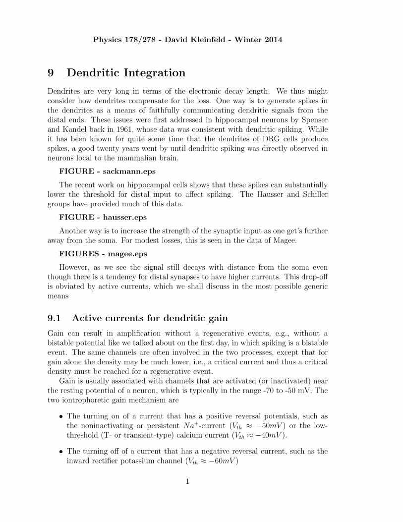
An independent mechanism for gain is localized spikes in specific dendrites. In par-ticular, Llinas showed that the dendrites actually produce Ca+2-based, as opposedto Na+-based spikes.
FIGURE - llinas.eps
The issue of localization of calcium currents was first addressed in the imagingexperiments of Ross, using a Ca2+ sensitive dye in slice. He found that selectiveregions of the distal dendrites could be excited, providing experimental evidence forthe idea of localized activation in dendrites.
FIGURE - imaging.eps
FIGURE - ross.eps
4


Coincidence detection across dendritic compartments. (A) Reconstruction of a layer 5 pyramidal neuron;the locations of recording pipettes (soma, black; dendrite, red ) are depicted schematically. (B) Distalcurrent injection of 1.1 nA in the shape of an EPSP (Istim, red ) evoked only weak somatic (black)depolarization (upper panel ). Threshold current injection (5 ms) into the soma (black) produced an APthat propagated back into the apical dendritic arbor (backpropagating action potential, bAP, red trace,middle panel ). Combination of somatic and dendritic current injection generates several somatic APs anda dendritic Ca2+ spike (backpropagating action potential–activated Ca2+ spike �ring, BAC �ring; lowerpanel ). The dashed line indicates the current threshold for a dendritic Ca2+ spike alone. (C) A dendriticCa2+ spike was evoked by 2 nA current injection into the apical dendrite alone. Thus, the bAP reducedthe threshold for dendritic Ca2+ spike by 0.9 nA.


Related Documents