Eng’r Form: SC-933 Revised 1-20-09 Rev. N SPECIFICATION 9-3800 Page 1 of 26 Amphenol Corporation FSCM NO. 77820 Sidney, New York U TITLE STANDARD “SPECIAL USE” DESCRIPTION ENGINEERING DRAWING INTERPRETATION Revisions REV. LETTER ISSUE NUMBER ORIGINATOR DATE APPROVAL M A6808 S. DOMBROWSKI 1/19/09 N B1062 D. FREAR 2/21/11 Document Origination (Amphenol) APPROVALS: SIGNATURES PREPARED BY: D. B. TOMERO ENGINEER IN CHARGE: N. A. HAYNER DESIGN MANAGER: D. MACAVOY DESIGN ACTIVITY GROUP: MILAERO 3/23/88 DATE: 3/23/88 IMAGED / Jun . 09 2011, 1:09

Welcome message from author
This document is posted to help you gain knowledge. Please leave a comment to let me know what you think about it! Share it to your friends and learn new things together.
Transcript

Eng’r Form: SC-933 Revised 1-20-09
Rev. N
SPECIFICATION 9-3800 Page 1 of 26 Amphenol Corporation FSCM NO. 77820 Sidney, New York
U
TITLE
STANDARD “SPECIAL USE”
DESCRIPTION
ENGINEERING DRAWING INTERPRETATION
Revisions REV. LETTER ISSUE NUMBER ORIGINATOR DATE APPROVAL
M A6808 S. DOMBROWSKI 1/19/09 N B1062 D. FREAR 2/21/11
Document Origination (Amphenol) APPROVALS: SIGNATURES PREPARED BY: D. B. TOMERO ENGINEER IN CHARGE: N. A. HAYNER DESIGN MANAGER: D. MACAVOY DESIGN ACTIVITY GROUP: MILAERO 3/23/88 DATE: 3/23/88
IMAGED / Jun . 09 2011, 1:09:58 PM

9-3800 Rev. N
AMPHENOL CORPORATION FSCM NO. 77820 Sidney, NY 13838
Page 2 of 26
Eng’r Form: SC-933-1 Revised 1-20-09
INDEX Location Location Angularity ¶ 3.2.3 Intersecting Surfaces ¶ 3.4.3 Axis ¶ 2.1 Maximum Material ¶ 2.7, ¶ 3.4.3 Basic ¶ 2.2 Condition (MMC) Burr ¶ 2.3 Parallelism ¶ 3.2.7 Centerline ¶ 3.4.5 Perpendicularity (see squareness) Chamfers ¶ 3.5.6 Part Number/Drawing ¶ 8.0 Designation Circularity (see roundness) Positional Tolerance ¶ 2.11, ¶ 3.3.3 Circular Runout. ¶ 3.2.10.1 Profile Tolerancing ¶ 3.2.8 Clinch Nut Installation ¶ 9.0 per Military Specification Reference ¶ 2.10 Concentricity ¶ 3.2.4 Regardless of Feature Size ¶ 2.9 Corners ¶ 3.1 (RFS) Countersinks ¶ 3.4.5-3.5.5 Reliability ¶ 4.9 Cylindricity ¶ 3.2.5 Roundness ¶ 3.2.9 Datum ¶ 2.4 Runout ¶ 3.2.10 Definitions ¶ 2.0 Dimensions ¶ 3.0, ¶ 5.0 Screw Threads ¶ 3.5 Drilled Hole Depth ¶ 3.4.1 Size ¶ 3.3.1 - 3.3.3 Spot Face ¶ 3.4.2 Eccentricity ¶ 3.2.4, Squareness ¶ 3.2.11, ¶ 3.3.2 ¶ 3.3.3 Straightness ¶ 3.2.12, ¶ 3.3.1 Feature ¶ 2.5 Surface Finish ¶ 6.0 Flatness ¶ 3.2.6 Symbols ¶ 4.0 Form Tolerance ¶ 2.6, ¶ 3.2.2 Symmetry ¶ 3.2.13 Full Indicator Movement ¶ 2.13 (FIM) True Position ¶ 2.14 Geometric Tolerance ¶ 3.2 Figure 1 - Characteristics and Symbols Chart See Sheet 8
IMAGED / Jun . 09 2011, 1:09:58 PM

9-3800 Rev. N
AMPHENOL CORPORATION FSCM NO. 77820 Sidney, NY 13838
Page 3 of 26
Eng’r Form: SC-933-1 Revised 1-20-09
1.0 SCOPE: 1.1 To define and interpret notes, special symbols, and dimensioning practices
commonly used on Amphenol Aerospace Operations Engineering drawings. In those instances where additional clarification is necessary, ASME Standard Y14.5M shall be used.
1.2 Applicable Documents: The following specifications of the latest issue in effect on date of issuance of
purchase order form a part of this specification to the extent specified herein: 1.2.1 Military- MIL-S-7742 Screw Threads, Optimum Selected Series, General Specification for 1.2.2 Federal- Fed-Std-H28 Screw-Thread Standards for Federal Services 1.2.3 American Society of Mechanical Engineers (ASTM)- ASME Y14.5M Dimensioning and Tolerancing, Engineering Drawing and Related Documentation Practices 1.2.4 Amphenol- 9-2640 Surface Roughness, Waviness and Lay 9-9318 Equivalent Specifications Amphenol Quality Standards Manual 1.3 Precedence: a. In all cases where the requirements on the drawing conflict with this document
or another document referenced herein, the drawing requirements shall govern. b. In all cases where the requirements of this document conflict with another
document referenced herein, this document shall govern.
IMAGED / Jun . 09 2011, 1:09:58 PM

Eng’r Form: SC-933-1 Revised 1-20
2.0 DEFINITIONS: 2.1 Axis: An imaginary straight line about which a part or feature may revolve or
about which they may be arranged. 2.2 Basic: (See Figure II). Used to express a desired condition for reference
such as "TAPER 1:5 BASIC". A basic condition does not have a specifically stated individual tolerance but varies within limits established by the tolerances on other dimensions.
2.3 Burr: Sharp projections on the edges of parent material. 2.3.1 Acceptable Imperfections
and does not impair the proper function of the end product. 2.3.2 Unacceptable Imperfections 1. Burrs, as defined above, are unacceptable. 2. Lightly attached 3. External excess material, sharp enough to cut hand, is not acceptable. 4. Open recess under excess material, where bottom of recess is not visible, is not
acceptable. 5. Visible exce
acceptable.
2.4 Datum: (symbol be exact for purposes of computation from which the location or geometry (form) of features of a part may be established.
Example: Datum diameter on a taper. 2.5 Feature: A specific characteristic or component portion of a part that may include one
or more surfaces such as a hole, screw thread, profile, face or slot. 2.6 Form Tolerance:
shapes. More specifically the tolerance controls the conditions of straightness, flatness, roundness, etc.
2.7 Maximum Material Condition (abbreviated MMC or symbol where a feature contains the maximum amount of material, e.g., minimum hole size or maximum shaft size.
2.8 Least Material Condition (abbreviated LMC or symbol feature contains the least amount of material,size.
9-AMPHENOL CORPORATION
Sidney, NY 13838
20-09
DEFINITIONS:
An imaginary straight line about which a part or feature may revolve or about which they may be arranged.
(See Figure II). Used to express a desired condition for reference such as "TAPER 1:5 BASIC". A basic condition does not have a specifically stated individual tolerance but varies within limits established by the tolerances on other dimensions.
Sharp projections on the edges of parent material.
Acceptable Imperfections - Excess material is acceptable provided it is firmly attached and does not impair the proper function of the end product.
Unacceptable Imperfections -
Burrs, as defined above, are unacceptable. Lightly attached excess material on any surface is not acceptable.External excess material, sharp enough to cut hand, is not acceptable.Open recess under excess material, where bottom of recess is not visible, is not acceptable. Visible excess material, that cannot be inspected as being firmly attached, is not acceptable.
(symbol ) A theoretical point, axis, line, plane, cylinder, etc., assumed to be exact for purposes of computation from which the location or geometry (form) of
part may be established.
Example: Datum diameter on a taper.
A specific characteristic or component portion of a part that may include one or more surfaces such as a hole, screw thread, profile, face or slot.
Form Tolerance: The tolerance assigned to control the form of various geometrical shapes. More specifically the tolerance controls the conditions of straightness, flatness,
Maximum Material Condition (abbreviated MMC or symbol ature contains the maximum amount of material, e.g., minimum hole size or
maximum shaft size.
Least Material Condition (abbreviated LMC or symbol ): feature contains the least amount of material, e.g., maximum hole size, minimum shaft
-3800 Rev. N
FSCM NO. 77820
Page 4 of 26
An imaginary straight line about which a part or feature may revolve or
(See Figure II). Used to express a desired condition for reference purposes, such as "TAPER 1:5 BASIC". A basic condition does not have a specifically stated individual tolerance but varies within limits established by the tolerances on
Excess material is acceptable provided it is firmly attached
excess material on any surface is not acceptable. External excess material, sharp enough to cut hand, is not acceptable. Open recess under excess material, where bottom of recess is not visible, is not
not be inspected as being firmly attached, is not
) A theoretical point, axis, line, plane, cylinder, etc., assumed to be exact for purposes of computation from which the location or geometry (form) of
A specific characteristic or component portion of a part that may include one or more surfaces such as a hole, screw thread, profile, face or slot.
lerance assigned to control the form of various geometrical shapes. More specifically the tolerance controls the conditions of straightness, flatness,
Maximum Material Condition (abbreviated MMC or symbol ): The condition ature contains the maximum amount of material, e.g., minimum hole size or
The condition where a e.g., maximum hole size, minimum shaft
IMAGED / Jun . 09 2011, 1:09:58 PM

Eng’r Form: SC-933-1 Revised 1-20
2.0 DEFINITIONS:
2.9 Regardless of Feature Size (abbreviated RFS or symbol tolerance of position or form must be met irrespective of where the feature lies within its size tolerance.
2.10 Reference (abbreviated REF)
tolerance and are used for informational purposenot govern machining or inspection except in some cases, REF is used for dimensions shown in more than one view on a drawing to eliminate duplicating tolerances on a drawing.
2.11 Positional Tolerance:
location. 2.12 Radius: A smooth curve that is tangent to adjacent surfaces, lies wholly
within its tolerance zone, 2.13 Full Indicator Movement (abbreviated FIM)
within a specified limit,
2.14 True Position (abbreviated (TP) or symbol location of a feature.
3.0 INTERPRETATION:
Dimensions and tolerances are in inches unless othe
3.1 Corners: 3.1.1 External Corners
NOT concave.
9-AMPHENOL CORPORATION
Sidney, NY 13838
20-09
DEFINITIONS: (continued)
Regardless of Feature Size (abbreviated RFS or symbol ):tolerance of position or form must be met irrespective of where the feature lies within its
Reference (abbreviated REF): Dimensions so labeled are usually without tolerance and are used for informational purposes only. Such dimensions do not govern machining or inspection except in some cases, REF is used for dimensions shown in more than one view on a drawing to eliminate duplicating tolerances on a drawing.
Positional Tolerance: The total permissible variation from the perfect
A smooth curve that is tangent to adjacent surfaces, lies wholly within its tolerance zone, and has no flats or reversals.
Full Indicator Movement (abbreviated FIM)- The total or full movwithin a specified limit, that the dial hand of an indicator gage may move.
True Position (abbreviated (TP) or symbol )- The theoretically exact location of a feature.
INTERPRETATION:
Dimensions and tolerances are in inches unless otherwise specified.
External Corners- May be convex or straight, within the tolerance zone, but
-3800 Rev. N
FSCM NO. 77820
Page 5 of 26
): The condition where tolerance of position or form must be met irrespective of where the feature lies within its
: Dimensions so labeled are usually without s only. Such dimensions do
not govern machining or inspection except in some cases, REF is used for dimensions shown in more than one view on a drawing to eliminate
riation from the perfect
A smooth curve that is tangent to adjacent surfaces, lies wholly
The total or full movement that the dial hand of an indicator gage may move.
The theoretically exact
rwise specified.
May be convex or straight, within the tolerance zone, but
IMAGED / Jun . 09 2011, 1:09:58 PM

Eng’r Form: SC-933-1 Revised 1-20
3.0 INTERPRETATION
DRAWING CALLOUT
BREAK EDGE .XXX-.XXX
.XXX X 45°
CORNERS .000-.XXX (typically
.000-.020) OR SHARP CORNERS .000-.XXX
(typically .000-.005)
PARTS HAVING A DISTANCE
BETWEEN CORNERS GREATER THAN .060 AND NOTHING SPECIFIED ON DRAWING.
9-AMPHENOL CORPORATION
Sidney, NY 13838
20-09
INTERPRETATION: (continued)
DRAWING CALLOUT INTERPRETATION
.XXX
.XXX (typically .020) OR SHARP CORNERS
PARTS HAVING A DISTANCE BETWEEN CORNERS GREATER
THAN .060 AND NOTHING SPECIFIED ON DRAWING.
-3800 Rev. N
FSCM NO. 77820
Page 6 of 26
INTERPRETATION
IMAGED / Jun . 09 2011, 1:09:58 PM

Eng’r Form: SC-933-1 Revised 1-20
3.0 INTERPRETATION 3.1.2 Internal Corners:
(.005 - .020 R unless otherwise specified).
3.1.3 Internal & External Corners:
which are .060 or less in width and terminate in corners or fillets, shall retain a
minimum of 1/3
DRAWING CALLOUT
9-AMPHENOL CORPORATION
Sidney, NY 13838
20-09
INTERPRETATION: (continued)
Internal Corners: The resultant corner shall be a radius within the limits specified .020 R unless otherwise specified).
Internal & External Corners: Unless otherwise specified on the drawing, surfaces which are .060 or less in width and terminate in corners or fillets, shall retain a
3 the original surface after corners have been broken.
DRAWING CALLOUT INTERPRETATION
-3800 Rev. N
FSCM NO. 77820
Page 7 of 26
The resultant corner shall be a radius within the limits specified
Unless otherwise specified on the drawing, surfaces which are .060 or less in width and terminate in corners or fillets, shall retain a
the original surface after corners have been broken.
INTERPRETATION
IMAGED / Jun . 09 2011, 1:09:58 PM

Eng’r Form: SC-933-1 Revised 1-20
3.0 INTERPRETATION
3.2 Geometric Tolerances:or note. Figure 1 shows the approved symbol for each characteristic.
ANSI Y14.5M CHARACTERISTICS AND SYMBOLS CHART, REV 1982TYPE OF TOLERANCE
FOR
INDIVIDUAL
FEATURES FORM
INDIVIDUAL
OR RELATED PROFILE
FEATURES
FOR ORIENTATION
RELATED LOCATION
FEATURES
RUNOUT
9-AMPHENOL CORPORATION
Sidney, NY 13838
20-09
INTERPRETATION: (continued)
Geometric Tolerances: Geometric characteristics are specified on the drawing by symbol or note. Figure 1 shows the approved symbol for each characteristic.
ANSI Y14.5M CHARACTERISTICS AND SYMBOLS CHART, REV 1982TOLERANCE GEOMETRIC CHARACTERISTICS
STRAIGHTNESS
FLATNESS
FORM CIRCULARITY (ROUNDNESS)
CYLINDRICITY
PROFILE OF A LINE
PROFILE PROFILE OF A SURFACE
ALL AROUND-PROFILE
ANGULARITY
ORIENTATION PERPENDICULARITY
PARALLELISM
POSITION
LOCATION CONCENTRICITY/ COAXIALITY
SYMMETRY (THE USE OF "POSITION" IS PREFERRED)
CIRCULAR RUNOUT
RUNOUT TOTAL RUNOUT
AT MAXIMUM MATERIAL CONDITION
AT LEAST MATERIAL CONDITION
REGARDLESS OF FEATURE SIZE
PROJECTED TOLERENCE ZONE
DIAMETER
BASIC DIMENSION (TRUE POSITION)
REFERENCE DIMENSION
DATUM FEATURE
DATUM TARGET
TARGET POINT
FROM ANSI Y14.5M. REV'D. 1982; AAO ISSUE 02/05/88
FIGURE 1
-3800 Rev. N
FSCM NO. 77820
Page 8 of 26
Geometric characteristics are specified on the drawing by symbol or note. Figure 1 shows the approved symbol for each characteristic.
ANSI Y14.5M CHARACTERISTICS AND SYMBOLS CHART, REV 1982 GEOMETRIC CHARACTERISTICS
//
SYMMETRY (THE USE OF "POSITION" IS PREFERRED) NONE
MATERIAL CONDITION
∅ BASIC DIMENSION (TRUE POSITION)
(.500)
FROM ANSI Y14.5M. REV'D. 1982; AAO ISSUE 02/05/88
IMAGED / Jun . 09 2011, 1:09:58 PM

Eng’r Form: SC-933-1 Revised 1-20
3.0 INTERPRETATION: 3.2.1 Form Not Specified
part drawing, it is understood that the part will be acceptable if it is within the dimensional limits given. In Figure 2 the parallelism of opposite sides and the values of the angles between adjacsurfaces lie entirely within the zone defined by the dimensional limits.
3.2.2 Form Specified-
drawing, they apply to the entire feature concernthe subject feature to extend outside of size tolerance zones unless so specified on the drawing.
DRAWING CALLOUT
3.2.3 Angularity- Angularitycombination) which are at an angle, other than 90°.
DRAWING CALLOUTSYMBOL METHOD
9-AMPHENOL CORPORATION
Sidney, NY 13838
20-09
INTERPRETATION: (continued)
Form Not Specified- When permissible variations of form are not specified on the part drawing, it is understood that the part will be acceptable if it is within the dimensional limits given. In Figure 2 the parallelism of opposite sides and the values of the angles between adjacent sides may vary by any amount as long as all surfaces lie entirely within the zone defined by the dimensional limits.
- When permissible variations of form are specified on the part drawing, they apply to the entire feature concerned. Form tolerances do not permit the subject feature to extend outside of size tolerance zones unless so specified on
DRAWING CALLOUT INTERPRETATION
FIGURE 2
Angularity is the condition of surfaces, lines or axes (in any combination) which are at an angle, other than 90°.
DRAWING CALLOUT INTERPRETATIONNOTE METHOD
FIGURE 3
-3800 Rev. N
FSCM NO. 77820
Page 9 of 26
permissible variations of form are not specified on the part drawing, it is understood that the part will be acceptable if it is within the dimensional limits given. In Figure 2 the parallelism of opposite sides and the
ent sides may vary by any amount as long as all surfaces lie entirely within the zone defined by the dimensional limits.
When permissible variations of form are specified on the part ed. Form tolerances do not permit
the subject feature to extend outside of size tolerance zones unless so specified on
INTERPRETATION
is the condition of surfaces, lines or axes (in any
INTERPRETATION
IMAGED / Jun . 09 2011, 1:09:58 PM

Eng’r Form: SC-933-1 Revised 1-20
3.0 INTERPRETATION: 3.2.4 Concentricity- Concentricity
covers, spheres, etc., in any combination) have a common axis. condition wherein the axis of one surface of revolution is offset with respect to another. Where two surfaces of eccentricity is commonly specified in terms of the maximum permissible deviation from concentricity as shown in Figure 4.
3.2.4.1 Concentricity tolerance is .015 FIM RFS
DRAWING CALLOUTSYMBOL METHOD
IF ON DRAWING
ALLOWABLE PCB TAIL MISALIGNMENT
9-AMPHENOL CORPORATION
Sidney, NY 13838
20-09
INTERPRETATION: (continued)
Concentricity is the condition wherein surfaces revolution (cylinders, covers, spheres, etc., in any combination) have a common axis. condition wherein the axis of one surface of revolution is offset with respect to another. Where two surfaces of a part are intended to be closely concentric, the permissible eccentricity is commonly specified in terms of the maximum permissible deviation from concentricity as shown in Figure 4.
Concentricity tolerance is .015 FIM RFS unless otherwise specified on the drawing.
DRAWING CALLOUT INTERPRETATIONNOTE METHOD
When the part is mounted on surface "A", the other surfaces must be within the full indicator movement specified,
FIGURE 4
DRAWING CALLOUT IF ON DRAWING INTERPRETATION
FIGURE 4A ALLOWABLE PCB TAIL MISALIGNMENT
-3800 Rev. N
FSCM NO. 77820
Page 10 of 26
is the condition wherein surfaces revolution (cylinders, covers, spheres, etc., in any combination) have a common axis. Eccentricity is the condition wherein the axis of one surface of revolution is offset with respect to another.
a part are intended to be closely concentric, the permissible eccentricity is commonly specified in terms of the maximum permissible deviation from
unless otherwise specified on the drawing.
INTERPRETATION
When the part is mounted on surface
"A", the other surfaces must be within the full indicator movement specified,
RFS.
INTERPRETATION
IMAGED / Jun . 09 2011, 1:09:58 PM

Eng’r Form: SC-933-1 Revised 1-20
3.0 INTERPRETATION:
3.2.5 Cylindricity- Cylindricity, is the condition of a surface of revolution in which all elements form a cylinder.
3.2.6 Flatness- Flatness is the condition of a surface having all elements in one
p1ane.
DRAWING CALLOUTSYMBOL METHOD
9-AMPHENOL CORPORATION
Sidney, NY 13838
20-09
INTERPRETATION: (continued)
Cylindricity, is the condition of a surface of revolution in which all elements form a cylinder.
FIGURE 5
Flatness is the condition of a surface having all elements in one
DRAWING CALLOUT INTERPRETATIONNOTE METHOD
FIGURE 6
-3800 Rev. N
FSCM NO. 77820
Page 11 of 26
Cylindricity, is the condition of a surface of revolution in
Flatness is the condition of a surface having all elements in one
INTERPRETATION
IMAGED / Jun . 09 2011, 1:09:58 PM

Eng’r Form: SC-933-1 Revised 1-20
3.0 INTERPRETATION: 3.2.7 Parallelism- Parallelism
equidistant at all points.
DRAWING CALLOUTSYMBOL METHOD
3.2.8 Profile Tolerancing
variation along a line or surface and normal to it may be permitted. All profile dimensions are (TP) (without tolerances). Profile of a line and a surface are illustrated in Figures 8 and 9, respectively.
DRAWING SYMBOL METHOD
9-AMPHENOL CORPORATION
Sidney, NY 13838
20-09
INTERPRETATION: (continued)
Parallelism is the condition wherein two planes or straight lines are equidistant at all points.
DRAWING CALLOUT INTERPRETATIONNOTE METHOD
FIGURE 7
Profile Tolerancing-: Profile tolerancing is used where a uniform amount of variation along a line or surface and normal to it may be permitted. All profile dimensions are (TP) (without tolerances). Profile of a line and a surface are illustrated in Figures 8 and 9, respectively.
DRAWING CALLOUT (PROFILE OF A LINE)SYMBOL METHOD NOTE METHOD
FIGURE 8
-3800 Rev. N
FSCM NO. 77820
Page 12 of 26
is the condition wherein two planes or straight lines are
INTERPRETATION
is used where a uniform amount of variation along a line or surface and normal to it may be permitted. All profile dimensions are (TP) (without tolerances). Profile of a line and a surface are
CALLOUT (PROFILE OF A LINE) NOTE METHOD
IMAGED / Jun . 09 2011, 1:09:58 PM

Eng’r Form: SC-933-1 Revised 1-20
3.0 INTERPRETATION:
DRAWING CALLOUT (PROFILE OF A SURFACE)SYMBOL METHOD
3.2.9 Roundness (Circularity)
such as a cylinder or cone, where all points on a plane normal to the axis are equidistant from the axis.
DRAWING CALLOUT
SYMBOL METHOD
9-AMPHENOL CORPORATION
Sidney, NY 13838
20-09
INTERPRETATION: (continued)
DRAWING CALLOUT (PROFILE OF A SURFACE)SYMBOL METHOD NOTE METHOD
DIMENSIONS ARE (TP)
FIGURE 9
Roundness (Circularity)- Roundness is the condition on a surface of revolution, such as a cylinder or cone, where all points on a plane normal to the axis are equidistant from the axis.
DRAWING CALLOUT INTERPRETATIONNOTE METHOD
FIGURE 10
-3800 Rev. N
FSCM NO. 77820
Page 13 of 26
DRAWING CALLOUT (PROFILE OF A SURFACE) NOTE METHOD
Roundness is the condition on a surface of revolution, such as a cylinder or cone, where all points on a plane normal to the axis are
INTERPRETATION
IMAGED / Jun . 09 2011, 1:09:58 PM

Eng’r Form: SC-933-1 Revised 1-20
3.0 INTERPRETATION: 3.2.10 Runout- Runout
having a common axis. It establishes a means of controlling the functional relationship of two or more part features within the allowable errors of concentricity, perpendicularity and alignmeaccount variations in roundness, straightness, flatness, and parallelism of individual surfaces. An explanation of the runout tolerance is illustrated
in Figure 11.
SYMBOL METHOD
9-AMPHENOL CORPORATION
Sidney, NY 13838
20-09
INTERPRETATION: (continued)
Runout establishes composite form control of those features of a part having a common axis. It establishes a means of controlling the functional relationship of two or more part features within the allowable errors of concentricity, perpendicularity and alignment of the features. It also takes into account variations in roundness, straightness, flatness, and parallelism of individual surfaces. An explanation of the runout tolerance is illustrated
DRAWING CALLOUT SYMBOL METHOD NOTE METHOD
When mounted on datums C & D, designated surfaces constructed around or at right angles to a common axis must
be within total runout specified by A
INTERPRETATION
(continued on next sheet)
FIGURE 11
-3800 Rev. N
FSCM NO. 77820
Page 14 of 26
establishes composite form control of those features of a part having a common axis. It establishes a means of controlling the functional relationship of two or more part features within the allowable errors of
nt of the features. It also takes into account variations in roundness, straightness, flatness, and parallelism of individual surfaces. An explanation of the runout tolerance is illustrated
NOTE METHOD
When mounted on datums C & D, designated surfaces
constructed around or at right angles to a common axis must be within total runout specified by A
IMAGED / Jun . 09 2011, 1:09:58 PM

Eng’r Form: SC-933-1 Revised 1-20
3.0 INTERPRETATION:
3.2.10.1 Circular Runoutany fixed point during one complete rotation of the part about the datum axis.
3.2.11 Squareness (Perpendicularity)which are exactly at right angles to each other.
DRAWING CALLOUTSYMBOL METHOD
9-AMPHENOL CORPORATION
Sidney, NY 13838
20-09
INTERPRETATION: (continued)
INTERPRETATION (continued)
FIGURE 11 (continued)
Circular Runout- Circular runout is the maximom permissible surface varliation at any fixed point during one complete rotation of the part about the datum axis.
(Perpendicularity)- Squareness is the condition of surfaces or lines which are exactly at right angles to each other.
DRAWING CALLOUT INTERPRETATIONNOTE METHOD
All points on the surface must lietwo planes .003 apart, perpendicular to datum plane "A", and within the size tolerance zone.
FIGURE 12
-3800 Rev. N
FSCM NO. 77820
Page 15 of 26
Circular runout is the maximom permissible surface varliation at any fixed point during one complete rotation of the part about the datum axis.
Squareness is the condition of surfaces or lines
INTERPRETATION
All points on the surface must lie between two planes .003 apart, perpendicular to datum plane "A", and within the size
IMAGED / Jun . 09 2011, 1:09:58 PM

Eng’r Form: SC-933-1 Revised 1-20
3.0 INTERPRETATION:
3.2.12 Straightness- Straightness is the condition where an axis or an element of a surface does not deviate from a straight line.
DRAWING CALLOUTSYMBOL METHOD
NOTE: Running the leader from the symbol to the centerline indicates that the straightness tolerance applies to the axis.
3.2.13 Symmetry- Symmetry is the condition wherein the size and contour of a part or a feature are the same on opposite sides of a central plane, or a condition in which a feature is symmetrically disposed about the central plane of a datum feature.
DRAWING CALLOUTSYMBOL METHOD
9-AMPHENOL CORPORATION
Sidney, NY 13838
20-09
INTERPRETATION: (continued)
Straightness is the condition where an axis or an element of a surface does not deviate from a straight line.
DRAWING CALLOUT INTERPRETATIONNOTE METHOD
No longitudinal element of the cylindrical surface may deviatethan .003 from a straight line, regardless of size. (See paragraph 3.3.1 for effect at MMC.)
FIGURE 13
Running the leader from the symbol to the centerline indicates that the straightness tolerance applies to the axis.
Symmetry is the condition wherein the size and contour of a part or a feature are the same on opposite sides of a central plane, or a condition in which a feature is symmetrically disposed about the central plane of a datum feature.
DRAWING CALLOUT INTERPRETATIONNOTE METHOD
The median. plane of the slot, RFS, must lie between two planes .005 apart and equidistant from the median plane of the datum RFS.
FIGURE 14
-3800 Rev. N
FSCM NO. 77820
Page 16 of 26
Straightness is the condition where an axis or an element of a surface
INTERPRETATION
No longitudinal element of the cylindrical surface may deviate more than .003 from a straight line, regardless of size. (See paragraph 3.3.1 for effect at MMC.)
Running the leader from the symbol to the centerline indicates that the straightness
Symmetry is the condition wherein the size and contour of a part or a feature are the same on opposite sides of a central plane, or a condition in which a feature is symmetrically disposed about the central plane of a datum feature.
INTERPRETATION
The median. plane of the slot, RFS, must lie between two planes .005 apart and equidistant from the median plane of the datum RFS.
IMAGED / Jun . 09 2011, 1:09:58 PM

Eng’r Form: SC-933-1 Revised 1-20
3.0 INTERPRETATION: 3.3 Conditions of Form 3.3.1 Size and Straightness
material condition, "MMC", the part may have .005 error in straightness. As interpreted in Figure 15 (B) the maximum diathe effective straightness is limited to the specific tolerance. In Figure 15 (C) the minimum diameter pin in the same gage may have .015 error in straightness and still be accepted.
DRAWING CALLOUT
(A)
3.3.2 Size and Squarenesserror at maximum diameter. When a gage with a .627 hole is placed over the pin, the gage will accept up to .002 squareness error when the pin is at maximum diameter, Figure 16 (B). When the pin is at minimum diameter, however, the effective squareness etolerances.
9-AMPHENOL CORPORATION
Sidney, NY 13838
20-09
INTERPRETATION: (continued)
Conditions of Form Qualified by (MMC) (Maximum Material Condition):
Size and Straightness- In Figure 15 (A) the drawing specifies that at maximum material condition, "MMC", the part may have .005 error in straightness. As interpreted in Figure 15 (B) the maximum diameter pin is shown in a gage where the effective straightness is limited to the specific tolerance. In Figure 15 (C) the minimum diameter pin in the same gage may have .015 error in straightness and still be accepted.
INTERPRETATION
Maximum Diameter Pin
(B) Minimum Diameter Pin
FIGURE 15
Size and Squareness- The drawing specifies that the pin may have .002 squarenesserror at maximum diameter. When a gage with a .627 hole is placed over the pin, the gage will accept up to .002 squareness error when the pin is at maximum diameter, Figure 16 (B). When the pin is at minimum diameter, however, the effective squareness error may be as high as .003 and still stay within stated
-3800 Rev. N
FSCM NO. 77820
Page 17 of 26
Qualified by (MMC) (Maximum Material Condition):
In Figure 15 (A) the drawing specifies that at maximum material condition, "MMC", the part may have .005 error in straightness. As
meter pin is shown in a gage where the effective straightness is limited to the specific tolerance. In Figure 15 (C) the minimum diameter pin in the same gage may have .015 error in straightness and
Minimum Diameter Pin (C)
The drawing specifies that the pin may have .002 squareness error at maximum diameter. When a gage with a .627 hole is placed over the pin, the gage will accept up to .002 squareness error when the pin is at maximum diameter, Figure 16 (B). When the pin is at minimum diameter, however, the
rror may be as high as .003 and still stay within stated
IMAGED / Jun . 09 2011, 1:09:58 PM

Eng’r Form: SC-933-1 Revised 1-20
3.0 INTERPRETATION:
(A)
3.3.3 Size and Positional Tolerancing for Coaxialityhave .010 coaxial error at maximum diameters of .990 and .500, and when inserted in a gage will reflect those conditions Figure 17 (B). A minimum head will result in a permissible eccentricity of .020 Figure 17 (C). In Figure 1effect of several tolerances is pictured. Figure 17 (D) shows the maximum amounts the part may be out of coaxiality when head and shank both are at minimum diameters. Coaxiality at MMC is specified as within .010 diameter. As shown in Figure 17 (C), the part will still fit the gage with the head up to .010 coaxiality off (.020) if the head is at the minimum .980 diameter. If in addition the shank is at minimum .499 diameter, the coaxiality may be .0005 more, or .0105 total (.021), as shown here.
DRAWING CALLOUT
(A)
Maximum diameters of head and shank
9-AMPHENOL CORPORATION
Sidney, NY 13838
20-09
INTERPRETATION: (continued)
INTERPRETATION
Maximum Diameter Pin
(B) Minimum Diameter Pin
FIGURE 16
Size and Positional Tolerancing for Coaxiality- The part in Figure 17 (A) may have .010 coaxial error at maximum diameters of .990 and .500, and when inserted in a gage will reflect those conditions Figure 17 (B). A minimum head will result in a permissible eccentricity of .020 Figure 17 (C). In Figure 1effect of several tolerances is pictured. Figure 17 (D) shows the maximum amounts the part may be out of coaxiality when head and shank both are at minimum diameters. Coaxiality at MMC is specified as within .010 diameter. As
Figure 17 (C), the part will still fit the gage with the head up to .010 coaxiality off (.020) if the head is at the minimum .980 diameter. If in addition the shank is at minimum .499 diameter, the coaxiality may be .0005 more, or .0105
shown here.
INTERPRETATION
Maximum diameters of head and shank
(B)
Minimum diameter of head and maximum diameter of shank
(C)
Minimum
FIGURE 17
-3800 Rev. N
FSCM NO. 77820
Page 18 of 26
Minimum Diameter Pin (C)
part in Figure 17 (A) may have .010 coaxial error at maximum diameters of .990 and .500, and when inserted in a gage will reflect those conditions Figure 17 (B). A minimum head will result in a permissible eccentricity of .020 Figure 17 (C). In Figure 17 (D) the combined effect of several tolerances is pictured. Figure 17 (D) shows the maximum amounts the part may be out of coaxiality when head and shank both are at minimum diameters. Coaxiality at MMC is specified as within .010 diameter. As
Figure 17 (C), the part will still fit the gage with the head up to .010 coaxiality off (.020) if the head is at the minimum .980 diameter. If in addition the shank is at minimum .499 diameter, the coaxiality may be .0005 more, or .0105
Minimum diameters of both head and shank
(D)
IMAGED / Jun . 09 2011, 1:09:58 PM

Eng’r Form: SC-933-1 Revised 1-20
3.0 INTERPRETATION:
3.4 Specification of Features 3.4.1 Drilled Hole Depth
full diameter and not the depth of drill point penetration.
3.4.2 Spot Faces- The
shall, in all instances, clean up the spot face area but in no case exceed .020 max. taken from the lowest point. See example. (NOTE: For thin parts, this .020 maximum should be suitably reduced).
3.4.3 Intersecting Surfaces
corners are understood to be measured to the theoretical point of intersection.
3.4.4 Vertical and Horizontal Centerlines:
subject to the tolerance shown in the standard block unless otherwise specified. However, if features appearing on these centerlines are located by True Position dimensioning and tolerancing, the 90° is still appearing in the standard tolerance block is no longer applicable.
9-AMPHENOL CORPORATION
Sidney, NY 13838
20-09
INTERPRETATION: (continued)
Specification of Features-
Drilled Hole Depth- Is the depth of the full diameter and not the depth of drill point penetration.
The depth of spot facing shall, in all instances, clean up the spot face area but in no case exceed .020 max. taken from the lowest point. See example. (NOTE: For thin parts, this .020 maximum should be suitably reduced).
Intersecting Surfaces- Dimensions to corners are understood to be measured to the theoretical point of intersection.
Vertical and Horizontal Centerlines: Centerlines are understood to be at 90° and subject to the tolerance shown in the standard block unless otherwise specified. However, if features appearing on these centerlines are located by True Position dimensioning and tolerancing, the 90° is still understood, but the angular tolerance appearing in the standard tolerance block is no longer applicable.
-3800 Rev. N
FSCM NO. 77820
Page 19 of 26
Centerlines are understood to be at 90° and subject to the tolerance shown in the standard block unless otherwise specified. However, if features appearing on these centerlines are located by True Position
understood, but the angular tolerance appearing in the standard tolerance block is no longer applicable.
IMAGED / Jun . 09 2011, 1:09:58 PM

Eng’r Form: SC-933-1 Revised 1-20
3.0 INTERPRETATION:
3.4.5 Countersinks on Cylindrical Surfaces
DRAWING CALLOUT
3.5 Screw Threads
3.5.1 Standard Screw Threadsotherwise specified.
3.5.2 Full Thread
3.5.2.1 Full Thread (External)point (A) of the first thread which attains fmaximum material condition.
DRAWING CALLOUT
9-AMPHENOL CORPORATION
Sidney, NY 13838
20-09
INTERPRETATION: (continued)
Countersinks on Cylindrical Surfaces-
DRAWING CALLOUT INTERPRETATION
FIGURE 18
Standard Screw Threads- Shall be in accordance with specification unless otherwise specified.
Full Thread (External)- Thread is measured from the center of the thread point (A) of the first thread which attains full form at both the root and the crest at maximum material condition.
INTERPRETATION
FIGURE 19
-3800 Rev. N
FSCM NO. 77820
Page 20 of 26
INTERPRETATION
Shall be in accordance with specification unless
Thread is measured from the center of the thread root at ull form at both the root and the crest at
INTERPRETATION
IMAGED / Jun . 09 2011, 1:09:58 PM

Eng’r Form: SC-933-1 Revised 1-20
3.0 INTERPRETATION:
3.5.2.2 Full Thread (Internal)point (B) of the first thread which attains full form at both the root and the crest at maximum material conditions.
DRAWING CALLOUT
3.5.3 Conventional and
3.5.3.1 Conventional- A 45° corner chamfer is usually provided where threads are cut by single lathe tools or by tap and die methods. The resultant thread has a thin, sharp partial starting thread, Figure 21 (A), which is undesirableavoid inadvertent damage or possible cutting of the user's hands. (See para. 3.5.6).
(A) - Partial thread resulting from conventional start threading
9-AMPHENOL CORPORATION
Sidney, NY 13838
20-09
INTERPRETATION: (continued)
Full Thread (Internal)- Thread is measured from the center of the thread root at point (B) of the first thread which attains full form at both the root and the crest at maximum material conditions.
INTERPRETATION
FIGURE 20
Conventional and Blunt Thread Starts-
A 45° corner chamfer is usually provided where threads are cut by single lathe tools or by tap and die methods. The resultant thread has a thin, sharp partial starting thread, Figure 21 (A), which is undesirable and must be removed to avoid inadvertent damage or possible cutting of the user's hands. (See para. 3.5.6).
Partial thread resulting from
conventional start threading
(B) - View of blunt start
FIGURE 21
-3800 Rev. N
FSCM NO. 77820
Page 21 of 26
Thread is measured from the center of the thread root at point (B) of the first thread which attains full form at both the root and the crest at
INTERPRETATION
A 45° corner chamfer is usually provided where threads are cut by single lathe tools or by tap and die methods. The resultant thread has a thin, sharp
and must be removed to avoid inadvertent damage or possible cutting of the user's hands. (See para. 3.5.6).
View of blunt start
IMAGED / Jun . 09 2011, 1:09:58 PM

Eng’r Form: SC-933-1 Revised 1-20
3.0 INTERPRETATION:
3.5.3.2 Blunt Start- "Blunt Start" designates the mechanical removal of the partial thread at the entering end of the thread. This is advised on threaded parts which are repeatedly assembled by hand, to prevent cross threading or nicking of the hands. As shown in Figure 21 (B), the surface of the blunt start is parallel with the axis of the work and rises from the root diameter to the major diameter in 120° max (by definition), measured at the point of the first full thread height. The blunt start may be generated by the "planetary method", resulting in the form seen in Figure 22 (A), or it may br produced by a separate operation shown in Figure 22 (B). The latter is formed by a cutter of .188 to .750 diameter. Either method prwith other parts or cross threading, and which requires no hand finishing.
* Actual length of rise is controlled by thread pitch and major diameter. EXAMPLE: in .500020 thread this is approximately 50°; in 3.0000
thread it is approximately 90°.
(A) - Blunt start is produced by planetary method
3.5.4 Area Back of External Threads
3.5.4.1 Rolled Thread- diameter.
3.5.4.2 Other than Rolled Threadsthread.
3.5.5 Countersinks for Threaded Holes± 2° to major diameter +.016,
9-AMPHENOL CORPORATION
Sidney, NY 13838
20-09
INTERPRETATION: (continued)
"Blunt Start" designates the mechanical removal of the partial thread at the entering end of the thread. This is advised on threaded parts which are repeatedly assembled by hand, to prevent cross threading or nicking of the hands.
s shown in Figure 21 (B), the surface of the blunt start is parallel with the axis of the work and rises from the root diameter to the major diameter in 120° max (by definition), measured at the point of the first full thread height. The blunt start
e generated by the "planetary method", resulting in the form seen in Figure 22 (A), or it may br produced by a separate operation - such as the shown in Figure 22 (B). The latter is formed by a cutter of .188 to .750 diameter. Either method produces a thread start which is resistant to damage from contact with other parts or cross threading, and which requires no hand finishing.
* Actual length of rise is controlled by thread
pitch and major diameter. EXAMPLE: in .5000-proximately 50°; in 3.0000-16
thread it is approximately 90°.
Blunt start is produced by planetary method
(B) - Blunt start produced by cutter diameter
FIGURE 22
Area Back of External Threads-
Undercuts back of rolled threads permissible to minimum pitch
Other than Rolled Threads- Diameter must be within major diameter limits of
Countersinks for Threaded Holes- All holes for threading shall be countersunk 90° jor diameter +.016, -.000.
-3800 Rev. N
FSCM NO. 77820
Page 22 of 26
"Blunt Start" designates the mechanical removal of the partial thread at the entering end of the thread. This is advised on threaded parts which are repeatedly assembled by hand, to prevent cross threading or nicking of the hands.
s shown in Figure 21 (B), the surface of the blunt start is parallel with the axis of the work and rises from the root diameter to the major diameter in 120° max (by definition), measured at the point of the first full thread height. The blunt start
e generated by the "planetary method", resulting in the form seen in Figure such as the radius cut
shown in Figure 22 (B). The latter is formed by a cutter of .188 to .750 diameter. oduces a thread start which is resistant to damage from contact
with other parts or cross threading, and which requires no hand finishing.
Blunt start produced by cutter diameter
back of rolled threads permissible to minimum pitch
Diameter must be within major diameter limits of
All holes for threading shall be countersunk 90°
IMAGED / Jun . 09 2011, 1:09:58 PM
Eng’r Form: SC-933-1 Revised 1-20
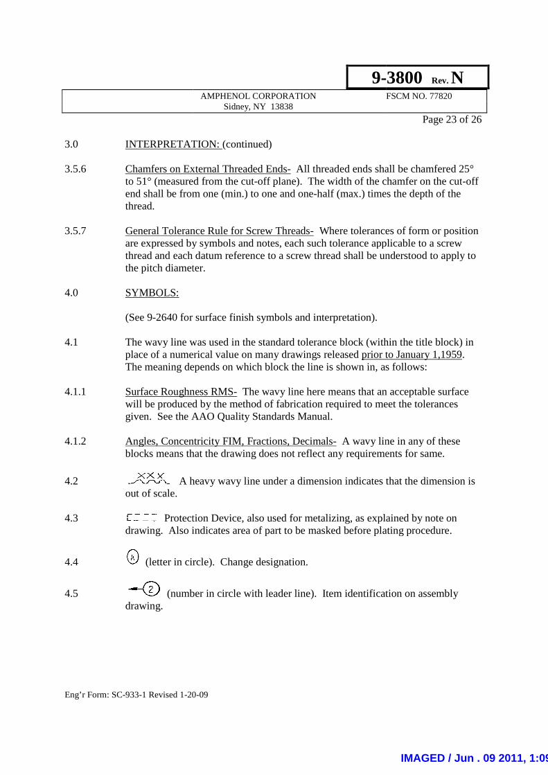
3.0 INTERPRETATION: 3.5.6 Chamfers on External Threaded Ends
to 51° (measured from the cutend shall be from one (mithread.
3.5.7 General Tolerance Rule for Screw Threads
are expressed by symbols and notes, each such tolerance applicable to a screw thread and each datum referenthe pitch diameter.
4.0 SYMBOLS: (See 9-2640 for surface finish symbols and interpretation). 4.1 The wavy line was used in the standard tolerance block (within the title block) in
place of a numericaThe meaning depends on which block the line is shown in, as follows:
4.1.1 Surface Roughness RMS
will be produced by the method of fabrication required to meet the tolerances given. See the AAO Quality Standards Manual.
4.1.2 Angles, Concentricity FIM, Fractions, Decimals
blocks means that the drawing does not reflect any requirements for same.
4.2 A heavy wavy line under a dimension indicates that the dimension is out of scale.
4.3 Protection Device, also used for
drawing. Also indicates area of part to be masked before plating procedure.
4.4 (letter in circle). Change designation.
4.5 (number in circle with leader line). Item identification on assembly drawing.
9-AMPHENOL CORPORATION
Sidney, NY 13838
20-09
INTERPRETATION: (continued)
Chamfers on External Threaded Ends- All threaded ends shall be chamfered 25° to 51° (measured from the cut-off plane). The width of the chamfer on the cutend shall be from one (min.) to one and one-half (max.) times the depth of the
General Tolerance Rule for Screw Threads- Where tolerances of form or position are expressed by symbols and notes, each such tolerance applicable to a screw thread and each datum reference to a screw thread shall be understood to apply to the pitch diameter.
2640 for surface finish symbols and interpretation).
The wavy line was used in the standard tolerance block (within the title block) in place of a numerical value on many drawings released prior to January The meaning depends on which block the line is shown in, as follows:
Surface Roughness RMS- The wavy line here means that an acceptable surface will be produced by the method of fabrication required to meet the tolerances given. See the AAO Quality Standards Manual.
Angles, Concentricity FIM, Fractions, Decimals- A wavy line in any of theseblocks means that the drawing does not reflect any requirements for same.
A heavy wavy line under a dimension indicates that the dimension is
Protection Device, also used for metalizing, as explained by note on indicates area of part to be masked before plating procedure.
(letter in circle). Change designation.
(number in circle with leader line). Item identification on assembly
-3800 Rev. N
FSCM NO. 77820
Page 23 of 26
All threaded ends shall be chamfered 25° off plane). The width of the chamfer on the cut-off
half (max.) times the depth of the
Where tolerances of form or position are expressed by symbols and notes, each such tolerance applicable to a screw
ce to a screw thread shall be understood to apply to
The wavy line was used in the standard tolerance block (within the title block) in prior to January 1,1959.
The meaning depends on which block the line is shown in, as follows:
wavy line here means that an acceptable surface will be produced by the method of fabrication required to meet the tolerances
A wavy line in any of these blocks means that the drawing does not reflect any requirements for same.
A heavy wavy line under a dimension indicates that the dimension is
, as explained by note on indicates area of part to be masked before plating procedure.
(number in circle with leader line). Item identification on assembly
IMAGED / Jun . 09 2011, 1:09:58 PM

Eng’r Form: SC-933-1 Revised 1-20
4.0 SYMBOLS: (continued)
4.6 (number in double assembly drawing to indicate parts which adapt unit to a particular specification.
4.7 I , II (Roman Numerals) used adjacent to connector outlets and cable terminations
to relate assembly picture to wiring 4.8 Identify when a separate note is used
used when drafted
used when CAD drawn
4.9 This symbol indicates that special controls are required. These controls shall be as required by the applicable reliability
5.0 DIMENSIONS OF PLATED OR PAINTED PARTS:
5.1 Inorganic Finishes
On all drawings which contain plating data, the dimensions are base material, unless otherwise specified and except for threads. On all otthose drawings not containing plating data, the dimensions shall be the final dimensions that exist after all fabrication operations specified on that drawing have been completed, unless otherwise specified.
The above policy is applicand/or parts released after March 1, 1958. New units, which contain components and/or parts released prior to March 1, 1958, shall reflect dimensions and tolerances identical to those reflected on the and/or parts.
9-AMPHENOL CORPORATION
Sidney, NY 13838
20-09
SYMBOLS: (continued)
(number in double circle with leader line). Item identification on assembly drawing to indicate parts which adapt unit to a particular specification.
(Roman Numerals) used adjacent to connector outlets and cable terminations to relate assembly picture to wiring diagram.
Identify when a separate note is used:
used when drafted
used when CAD drawn
RELIABILITY SYMBOL
This symbol indicates that special controls are required. These controls shall be as required by the applicable reliability documents specified on the drawing.
DIMENSIONS OF PLATED OR PAINTED PARTS:
Inorganic Finishes (Plating):
On all drawings which contain plating data, the dimensions are base material, unless otherwise specified and except for threads. On all other drawings, i.e.; those drawings not containing plating data, the dimensions shall be the final dimensions that exist after all fabrication operations specified on that drawing have been completed, unless otherwise specified.
The above policy is applicable only to those new units which contain components and/or parts released after March 1, 1958. New units, which contain components and/or parts released prior to March 1, 1958, shall reflect dimensions and tolerances identical to those reflected on the detail drawings of the components
-3800 Rev. N
FSCM NO. 77820
Page 24 of 26
circle with leader line). Item identification on assembly drawing to indicate parts which adapt unit to a particular specification.
(Roman Numerals) used adjacent to connector outlets and cable terminations
RELIABILITY SYMBOL
This symbol indicates that special controls are required. These controls shall be as documents specified on the drawing.
On all drawings which contain plating data, the dimensions are base material, her drawings, i.e.;
those drawings not containing plating data, the dimensions shall be the final dimensions that exist after all fabrication operations specified on that drawing have
able only to those new units which contain components and/or parts released after March 1, 1958. New units, which contain components and/or parts released prior to March 1, 1958, shall reflect dimensions and
detail drawings of the components
IMAGED / Jun . 09 2011, 1:09:58 PM
9-3800 Rev. N
AMPHENOL CORPORATION FSCM NO. 77820 Sidney, NY 13838
Page 25 of 26
Eng’r Form: SC-933-1 Revised 1-20-09
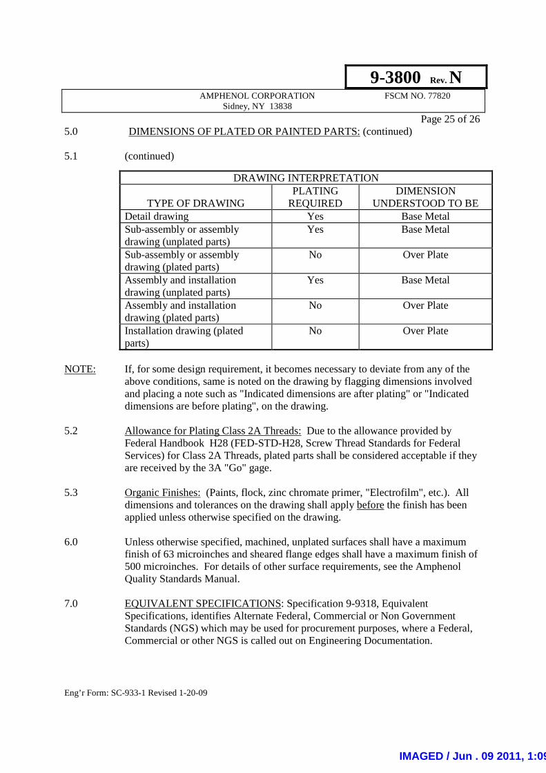
5.0 DIMENSIONS OF PLATED OR PAINTED PARTS: (continued) 5.1 (continued)
DRAWING INTERPRETATION
TYPE OF DRAWING PLATING
REQUIRED DIMENSION
UNDERSTOOD TO BE Detail drawing Yes Base Metal Sub-assembly or assembly drawing (unplated parts)
Yes Base Metal
Sub-assembly or assembly drawing (plated parts)
No Over Plate
Assembly and installation drawing (unplated parts)
Yes Base Metal
Assembly and installation drawing (plated parts)
No Over Plate
Installation drawing (plated parts)
No Over Plate
NOTE: If, for some design requirement, it becomes necessary to deviate from any of the
above conditions, same is noted on the drawing by flagging dimensions involved and placing a note such as "Indicated dimensions are after plating" or "Indicated dimensions are before plating", on the drawing.
5.2 Allowance for Plating Class 2A Threads: Due to the allowance provided by
Federal Handbook H28 (FED-STD-H28, Screw Thread Standards for Federal Services) for Class 2A Threads, plated parts shall be considered acceptable if they are received by the 3A "Go" gage.
5.3 Organic Finishes: (Paints, flock, zinc chromate primer, "Electrofilm", etc.). All
dimensions and tolerances on the drawing shall apply before the finish has been applied unless otherwise specified on the drawing.
6.0 Unless otherwise specified, machined, unplated surfaces shall have a maximum
finish of 63 microinches and sheared flange edges shall have a maximum finish of 500 microinches. For details of other surface requirements, see the Amphenol Quality Standards Manual.
7.0 EQUIVALENT SPECIFICATIONS: Specification 9-9318, Equivalent
Specifications, identifies Alternate Federal, Commercial or Non Government Standards (NGS) which may be used for procurement purposes, where a Federal, Commercial or other NGS is called out on Engineering Documentation.
IMAGED / Jun . 09 2011, 1:09:58 PM

9-3800 Rev. N
AMPHENOL CORPORATION FSCM NO. 77820 Sidney, NY 13838
Page 26 of 26
Eng’r Form: SC-933-1 Revised 1-20-09
8.0 PART NUMBERS: 8.1 When the Engineering Document depicts part numbers that generally follow the 2-6-3 digit format (e.g. 12-123456-123) or other similar configurations (e.g. 4-3-4) then “zero filling” may be used for part number designations as shown in the following examples:
Drawing Part Number Designation* Equivalent “Zero Filled” Part Number Designation* 21-33165-25 21-033156-025 88-556506-TG 88-556506-0TG 9-1234-1 09-001234-001 10-1234-12 10-001234-012 3700-123-123 3700-123-0123 DB-253A3-2A DB-0253A3-02A * Both designations are acceptable. The “zero filled” part number is primarily for Material Resource Planning (MRP) purposes and to allow the use of legacy data from previous MRP systems.
8.2 Lot Control Part Numbers (LC-): The following guidelines apply when a LC- drawing does not exist:
• The “10-“drawing is the controlling document. • At the discretion of Marketing and/or Planning the LC- prefix parts may
be supplied in lieu of the requested “10-“ part number. • At the discretion of Marketing and/or Planning the “10-“ part number may
be supplied in lieu of the LC- part number requested.
9.0 CLINCH NUT INSTALLATION GOVERNED BY MILITARY SPECIFICATION(S):
Assemblies using clinch nuts whose installation is governed by military specification may be installed in a panel with a thickness greater that that defined in the military specification as long as the clinch nut conforms to the torque and push-out requirements as defined on the part drawing.
9.1 All part drawings shall include a note which includes the torque and push-out requirements for the subject clinch nut.
10.0 SAFETY: Not Applicable to this Specification
IMAGED / Jun . 09 2011, 1:09:58 PM
Related Documents