Outdoor Living Today www.outdoorlivingtoday.com [email protected] Page 1 8x4 SpaceSaver Garden Shed - Double Door Assembly Manual Safety Point s and Other Considerations Our products are built for use based on proper installation and normal residential use, on level ground. Please follow the instruction manual when building your shed and retain the manual for future maintenance purposes. Some of the safety and usage measures you may wish to consider include: -snow load ratings vary by geographical location. If heavy or wet snowfall occurs, it is advisable to sweep the snow off the roof(s). -if the product is elevated, any structural and building code requirements are solely the customer's responsibility, and should be abided by. -in high or gusty wind conditions, it is advisable to keep the structure securely grounded. -have a regular maintenance plan to ensure screws, doors, windows and parts are tight. Customer agrees to hold Outdoor Living Today Partnership and any Authorized Dealers free of any liability for improper installation, maintenance and repair. Revision #13 January 15, 2013 In the event of a missing or broken piece, simply call the Outdoor Living Today Customer Support Line @ 1-888-658-1658 within 30 days of the delivery of your purchase. It is our commitment to you to courier replacement parts, free of charge, within 10 business days of this notification. Replacement parts will not be provided free of charge after the 30 day grace period. Thank you for purchasing an 8x4 SpaceSaver Garden Shed. Please take the time to identify all the parts prior to assembly.

Welcome message from author
This document is posted to help you gain knowledge. Please leave a comment to let me know what you think about it! Share it to your friends and learn new things together.
Transcript
Outdoor Living Today www.outdoorlivingtoday.com [email protected] 1
8x4 SpaceSaver GardenShed - Double DoorAssembly Manual
Safety Points and Other ConsiderationsOur products are built for use based onproper installation and normal residentialuse, on level ground. Please follow the instruction manual when building your shed and retain the manual for future maintenance purposes.
Some of the safety and usage measures you may wish to consider include:
-snow load ratings vary by geographical location. If heavy or wet snowfall occurs, it is advisable tosweep the snow off the roof(s). -if the product is elevated, any structural and building code requirements are solely the customer's responsibility, and should be abided by. -in high or gusty wind conditions, it is advisable to keep the structure securely grounded. -have a regular maintenance plan to ensure screws, doors, windows and parts are tight.
Customer agrees to hold Outdoor Living Today Partnership and any AuthorizedDealers free of any liability for improper installation, maintenance and repair.
Revision #13January 15, 2013
In the event of a missing or broken piece, simply call the Outdoor Living Today CustomerSupport Line @ 1-888-658-1658 within 30 days of the delivery of your purchase. It is our commitment to you to courier replacement parts, free of charge, within 10 business days of this notification. Replacement parts will not be provided free of charge after the 30 day grace period.
Thank you for purchasingan 8x4 SpaceSaver Garden Shed. Please take the time to identify all the parts prior to assembly.

Thank you for purchasing our 8x4 SpaceSaver Garden Shed Double Door.Please take the time to identify all the parts prior to assembly.
Parts List:A. Floor Section 1 - 45 ½” x 75” Large Floor Joist Frame (2 Joists unattached) 1 - 45 ½” X 21” Small Floor Joist Frame (2 Joists ATTACHED)2 - 1 ½” x 3 ½” x 72” Floor Joists5 - 1 ½” x 3 ½” x 45 ½” Floor Runners1 - 5/8” x 45 1/2” x 75” Plywood1 - 5/8” x 45 1/2” x 21” Plywood
B. Wall Section4 - 45 ½” x 75” - Wall Panels2 - 12” x 73” - Narrow Wall Panels2 - 9” x 45 ½”- Wall Extendors2 - - 45 ¼” Angle Wall Extendors 4 - 1 ½” x 2 ½” x 45 1/2” Wall Plates1 - ¾” x 3 ½” x 70” - Horizontal Wall Cleat1 - ¾” x 3 ½” x 21” - Horizontal Wall Cleat
Door, Jambs & Header2 - 31 1/2” X 72” Full Doors2 - 1 ½” x 3” x 73” Door Jambs1 - 2” x 3” x 78” Door Header-Long (Dado cut on edge)2 - 2” x 3” x 6 ½” Door Headers -Short (Dado cut on edge)2 - 1/2” x 2 1/2” x 72” - Vertical Interior Door Stops 1 - 1/2” x 2 1/2” x 68” - Top Horizontal Interior Door Stop 1 - 3/4” x 2 1/2” x 10” - Bottom Interior Door Stop 1 - 1/2” x 2 1/2” x 71” - Interior Vertical Door Flange
C. Rafter & Roof Section2 - Roof Panels 51 ½” x 55 ¾” (1-Left 1- Right )6 - 1 ½” x 2 ½” x 54” Rafters 2 - ½” x 4” x 48” Front Soffit2 - ½” x 3” x 48” Rear Soffit4 - Filler Shingles 5 1/2” Wide
D. Miscellaneous Section(Skirting, Facia ,Trim & Misc. Parts)2 - ½” x 4” x 54 1/8” Side Angle Cut Facia2 - ½” x 4” x 50” Front Facia2 - ½” x 4 ½” x 50” Rear Facia6 - ½” x 4 ½” x 45 1/4” Bottom Skirting4 - ½ x 2 ½” x 75” Corner Filler Trim2 - ½” x 2 ½” x 78 ¾” Vertical Door Trim2 - ½” x 2 ½” x 80” Front Side Corner Trim3 - ½” x 2 ½” x 88 ¾” Rear/Middle Trim 2 - ½ x 4 ½” x 78 ¾” Front Corner Trim2 - ½” x 4 ½” x 88 ¾” Rear Corner Trim1 - ½” x 1 1/4” x 64” Horizontal Door Trim2 - ½” x 2 1/2” x 10” Horizontal Narrow Wall Trim1 - 8”x 96” Strip of Roofing Felt 2 - ½” x 4” x 51 5/8” Roof Ridge Board2 - Detail Facia Plate (Larger for Rear Facia)1 - 45 ¼” Spare Piece of Siding
Note: We recommend you drill a 1/8” pilot hole for eachscrew, to avoid splitting wood. The hole depth should beequal to 3/4 the length of screw.
Toll Free 1-888-658-1658 www.outdoorlivingtoday.com [email protected] 2
Note: All Trim, Facia and Bottom Skirting pieces will be positioned rough face out when installed.

Toll Free 1-888-658-1658 www.outdoorlivingtoday.com [email protected] 3
8x4 SPACESAVER DD HARDWARE PACKAGE
Note: screws and nails shown actual size.
Tee Hinge x 6 Door Handle x 2
Square Drive Bit
Hardware Kit (Provided)
Safety Glasses Work Gloves
Safety Equipment Required (Not Provided)
Ladder
Screw Gun/Drill Tape MeasureHammer Wood Clamp
Level Pliers
Tools Required (Not Provided)
1/8” & 1/2” Drill Bits
Barrel Bolt
Utility Knife
2 1/2”
1 1/4”
3/4”Black
Simpson StrongTie x 8
2” Black
Cane Bolt
1 1/2” Finishing

Plywood Floor
Large FloorJoist Frame
Floor Joists (2)
Floor Runners (5)
Small FloorJoist Frame
Exploded Floor Section
A. Floor Section Exploded view of all parts necessary to complete Floor Section. Identify all partsprior to starting. Note: Floor Footprint is 96” wide x 45 1/2” deep.
Foundation Materialnot included.
1. Lay out Large Floor Joist Frame and 2 Floor Joists (1 1/2” x 3 1/2” x 72”) as illustrated above.Position Joists equally in Floor Joist Frame. Use Small Floor Joist Frame as a template to determinejoist position. Position Joist so flush with framing.
2. When correctly positioned, attach each Joist with 4 - 2 1/2” screws (2 per end). You can findthe Square Drive Bit for the screws in with the Hardware Kit Bag.
Flushwithframing
Front of SpaceSaver
Door Location. Small FloorJoist Frame
You can find theSquare Drive Bit, forthe screws, in theHardware Kit Bag.
Toll Free 1-888-658-1658 www.outdoorlivingtoday.com [email protected] 4
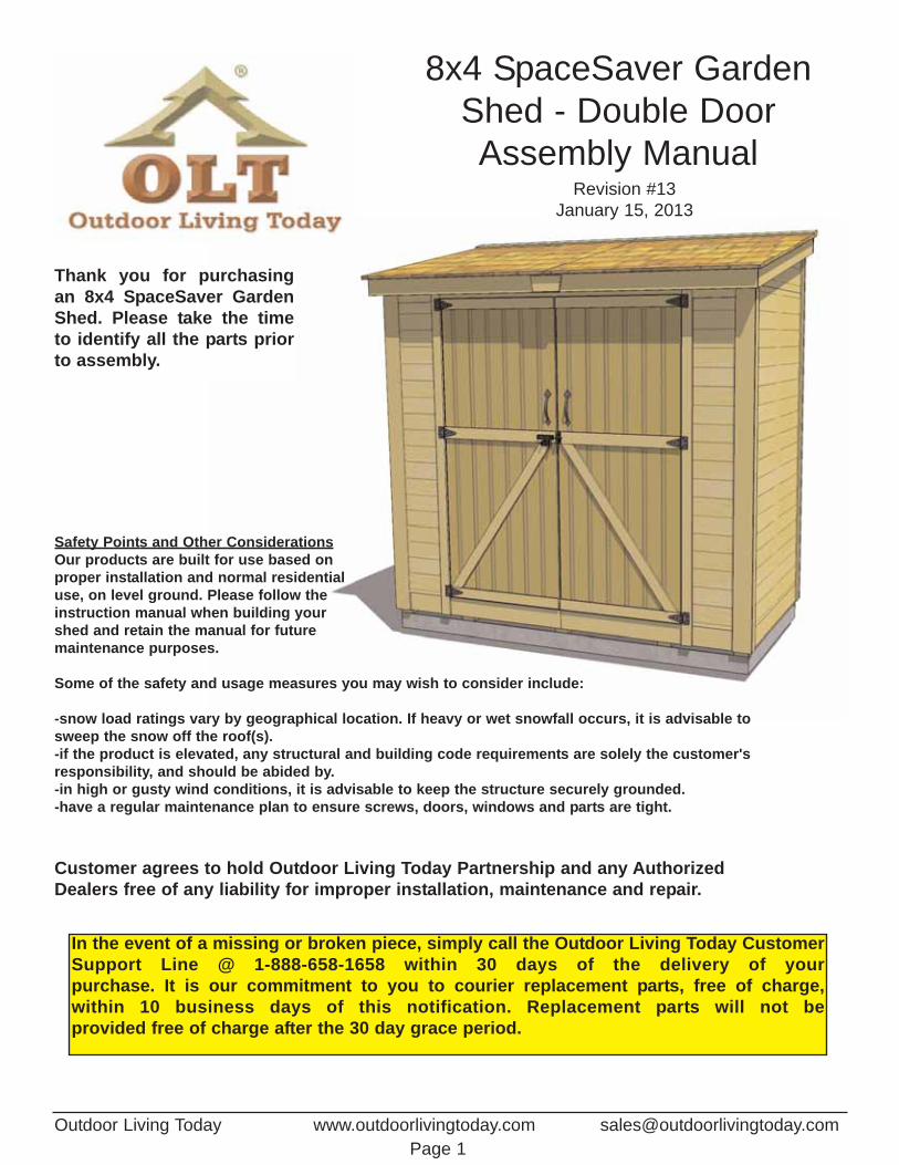
3. With Floor Joist Frames positionedtogether flush, attach with 6 - 2 1/2”screws.
4. Position and attach Floor Runners(1 1/2” x 3 1/2” x 45 1/2”) to completed floorframes with 6 - 2 1/2” screws per Runner. Make sure Runners are flush with outside of floor framing but not overhanging. Make sure 4th Runner is placed equally over seamwhere floor frames meet.
4th Runner
4th Runner
96”
45 1/2”
5. With Floor Runners attached, carefully flip the floor over and place on your foundation. Caution - you may need 2 people to assist you. Be careful when laying floor down not to bend or twistfloor. Note: The floor will be flipped over and floor runners will sit on your foundation. It is importantto note that having a level foundation is critical. Choosing a foundation will vary between regions.Typical foundations can be concrete pads or patio stones positioned underneath the floor runners.
6. When in place, level floor completelybefore proceeding.
7. Position Plywood Floor pieces (2) on top ofcompleted floor joists.
Flush with Floor Framing
Toll Free 1-888-658-1658 www.outdoorlivingtoday.com [email protected] 5
To help level Floor, locate Shim Shingles (used inpackaging) found in the edges of each Roof Panel.
Front
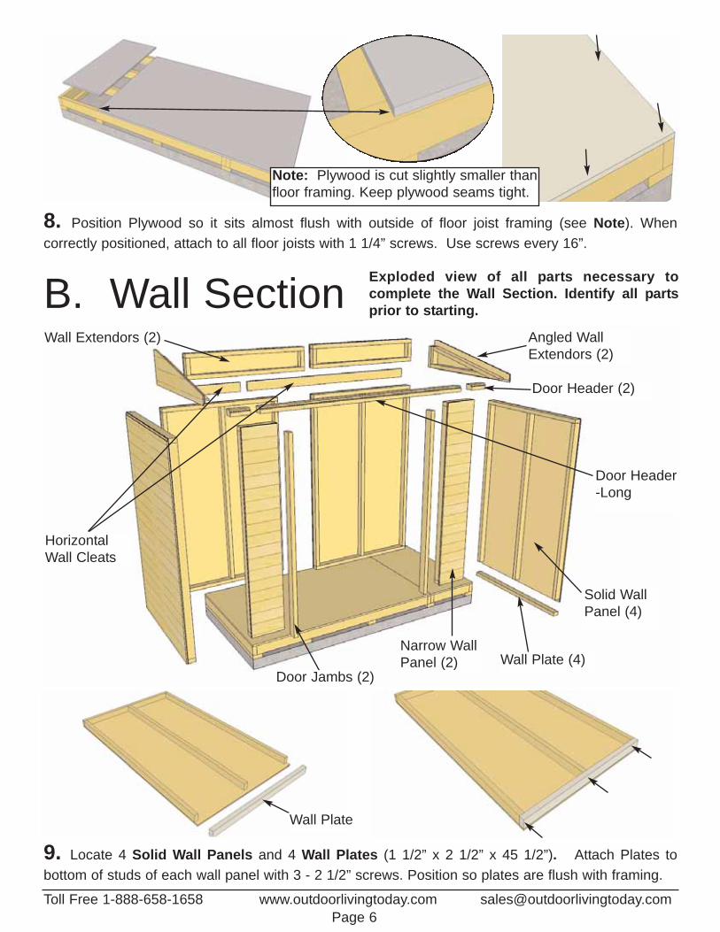
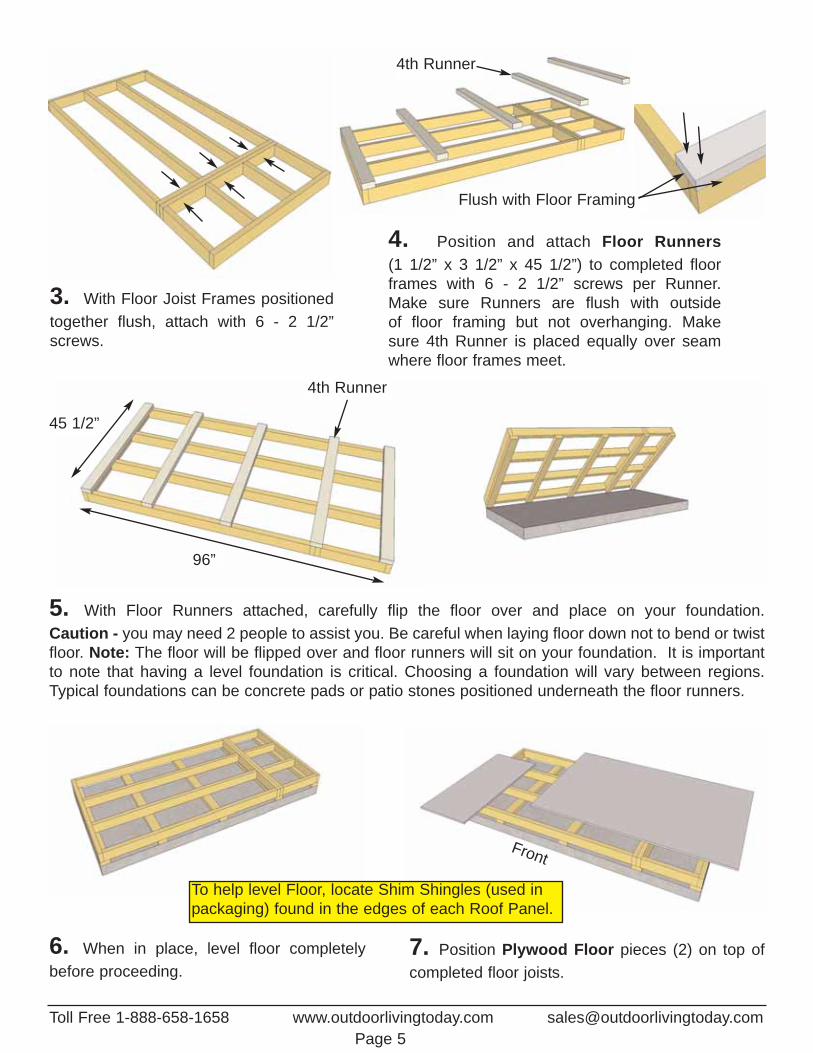
8. Position Plywood so it sits almost flush with outside of floor joist framing (see Note). When correctly positioned, attach to all floor joists with 1 1/4” screws. Use screws every 16”.
B. Wall Section Exploded view of all parts necessary to complete the Wall Section. Identify all partsprior to starting.
Angled WallExtendors (2)
Door Header -Long
Solid Wall Panel (4)
Wall Plate (4)Door Jambs (2)
Narrow WallPanel (2)
HorizontalWall Cleats
Wall Extendors (2)
Wall Plate
9. Locate 4 Solid Wall Panels and 4 Wall Plates (1 1/2” x 2 1/2” x 45 1/2”). Attach Plates to bottom of studs of each wall panel with 3 - 2 1/2” screws. Position so plates are flush with framing.
Door Header (2)
Note: Plywood is cut slightly smaller thanfloor framing. Keep plywood seams tight.
Toll Free 1-888-658-1658 www.outdoorlivingtoday.com [email protected] 6

10. Starting on Side, position a Solid Wall Panel on top of plywood floor.The Wall Panel bottom framing will sit flush with floor framing. Wall siding willoverhang the floor. Important: Make sure all walls are aligned in theirupright position. If not,water may leak into your shed. Unsure if panel is facing up or down? Recently attached Bottom Plate is on bottom of panel.
11. Outside 2x3 framing of wall panel should be flush with outside of floor framing when properlyaligned. Note: Siding will overhang the floor by approx. 1/2”. When positioned correctly, locate 2ndSolid Wall Panel and place in Corner.
Wall Plate Flushwith floor framing
Wall SidingOverhangsFloor by 1/2”
12. Butt both vertical wall studs of side and rear walls together and attach with 3 - 2 1/2” screws.Screw at the bottom, middle and top of stud to secure properly. Note: drill pilot holes in studs to prevent splitting.
Rear Sold Wall
Side
Solid
Wal
l
Do Not Attach Walls ToFloor until Step 30.
Optional - Caulkingseams will help preventmoisture from enteringyour shed. Caulking notincluded in kit.
Toll Free 1-888-658-1658 www.outdoorlivingtoday.com [email protected] 7
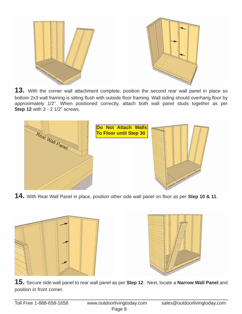
13. With the corner wall attachment complete, position the second rear wall panel in place so bottom 2x3 wall framing is sitting flush with outside floor framing. Wall siding should overhang floor byapproximately 1/2”. When positioned correctly, attach both wall panel studs together as per Step 12 with 3 - 2 1/2” screws.
14. With Rear Wall Panel in place, position other side wall panel on floor as per Step 10 & 11.
Rear Wall Panel
15. Secure side wall panel to rear wall panel as per Step 12. Next, locate a Narrow Wall Panel andposition in front corner.
Toll Free 1-888-658-1658 www.outdoorlivingtoday.com [email protected] 8
Do Not Attach WallsTo Floor until Step 30
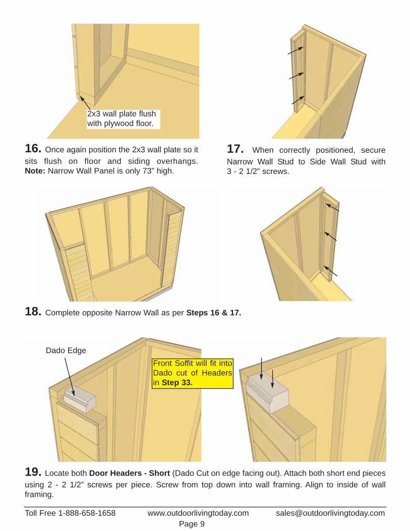
16. Once again position the 2x3 wall plate so itsits flush on floor and siding overhangs. Note: Narrow Wall Panel is only 73” high.
19. Locate both Door Headers - Short (Dado Cut on edge facing out). Attach both short end piecesusing 2 - 2 1/2” screws per piece. Screw from top down into wall framing. Align to inside of wall framing.
18. Complete opposite Narrow Wall as per Steps 16 & 17.
17. When correctly positioned, secureNarrow Wall Stud to Side Wall Stud with 3 - 2 1/2” screws.
2x3 wall plate flushwith plywood floor.
Toll Free 1-888-658-1658 www.outdoorlivingtoday.com [email protected] 9
Dado EdgeFront Soffit will fit intoDado cut of Headersin Step 33.
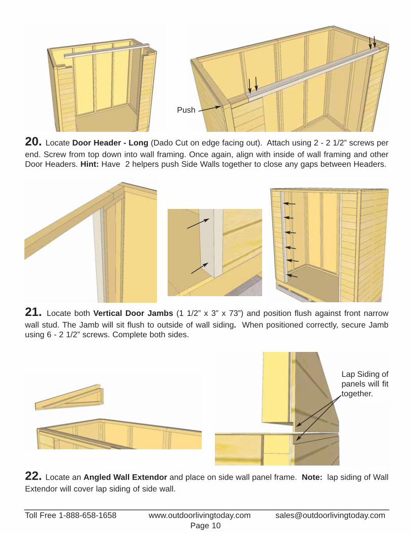
22. Locate an Angled Wall Extendor and place on side wall panel frame. Note: lap siding of WallExtendor will cover lap siding of side wall.
Lap Siding ofpanels will fittogether.
20. Locate Door Header - Long (Dado Cut on edge facing out). Attach using 2 - 2 1/2” screws perend. Screw from top down into wall framing. Once again, align with inside of wall framing and otherDoor Headers. Hint: Have 2 helpers push Side Walls together to close any gaps between Headers.
21. Locate both Vertical Door Jambs (1 1/2” x 3” x 73”) and position flush against front narrow wall stud. The Jamb will sit flush to outside of wall siding. When positioned correctly, secure Jambusing 6 - 2 1/2” screws. Complete both sides.
Push
Toll Free 1-888-658-1658 www.outdoorlivingtoday.com [email protected] 10
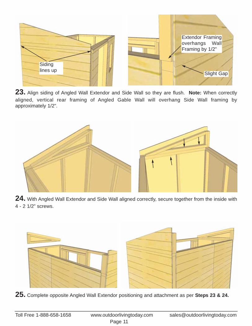
23. Align siding of Angled Wall Extendor and Side Wall so they are flush. Note: When correctlyaligned, vertical rear framing of Angled Gable Wall will overhang Side Wall framing by approximately 1/2”.
24. With Angled Wall Extendor and Side Wall aligned correctly, secure together from the inside with4 - 2 1/2” screws.
25. Complete opposite Angled Wall Extendor positioning and attachment as per Steps 23 & 24.
Extendor Framingoverhangs WallFraming by 1/2”
Sidinglines up Slight Gap
Toll Free 1-888-658-1658 www.outdoorlivingtoday.com [email protected] 11
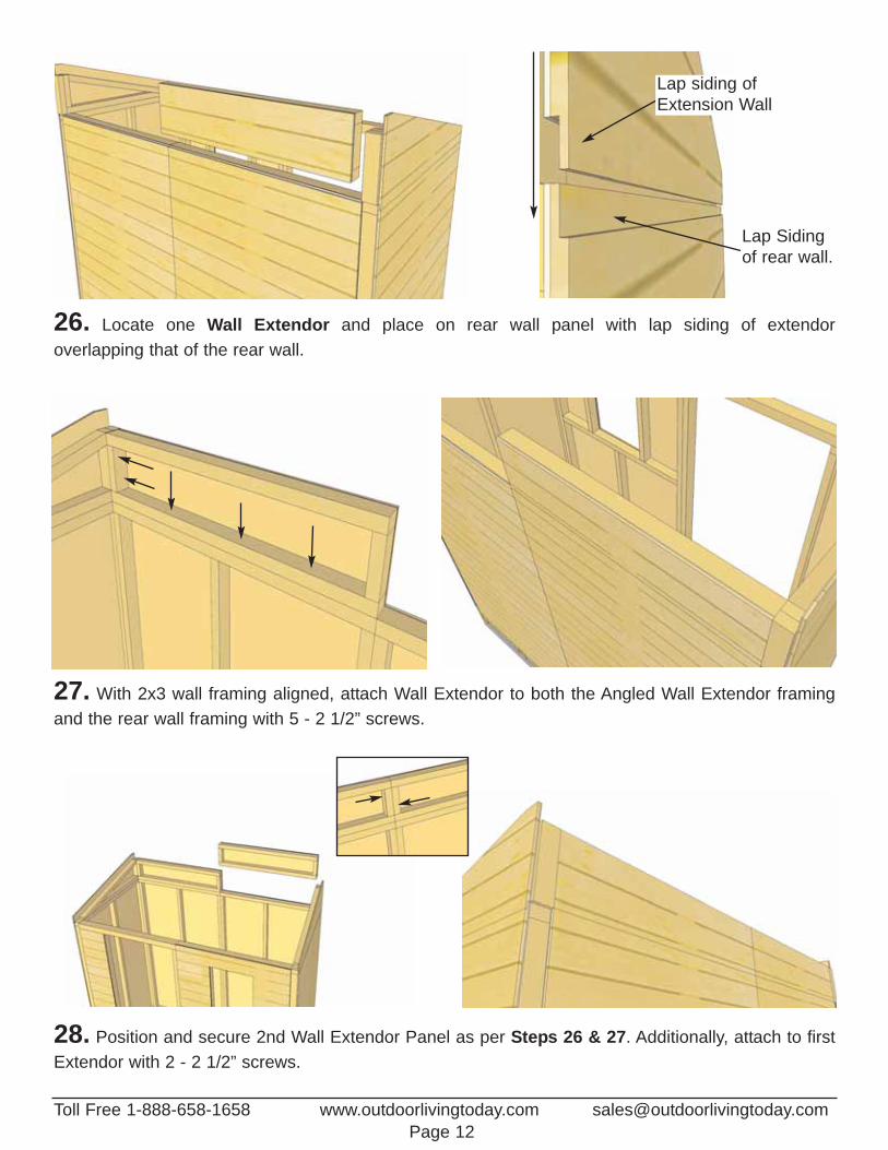
26. Locate one Wall Extendor and place on rear wall panel with lap siding of extendor overlapping that of the rear wall.
Lap siding ofExtension Wall
Lap Sidingof rear wall.
27. With 2x3 wall framing aligned, attach Wall Extendor to both the Angled Wall Extendor framingand the rear wall framing with 5 - 2 1/2” screws.
28. Position and secure 2nd Wall Extendor Panel as per Steps 26 & 27. Additionally, attach to firstExtendor with 2 - 2 1/2” screws.
Toll Free 1-888-658-1658 www.outdoorlivingtoday.com [email protected] 12
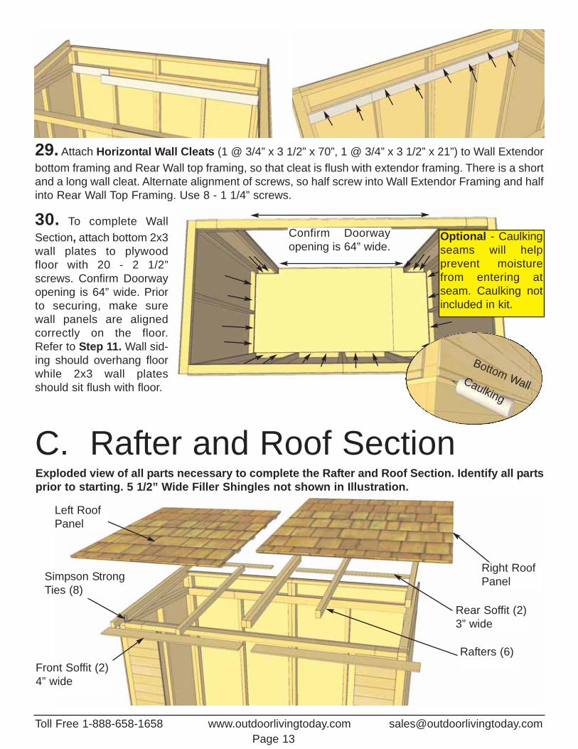
29. Attach Horizontal Wall Cleats (1 @ 3/4” x 3 1/2” x 70”, 1 @ 3/4” x 3 1/2” x 21”) to Wall Extendorbottom framing and Rear Wall top framing, so that cleat is flush with extendor framing. There is a shortand a long wall cleat. Alternate alignment of screws, so half screw into Wall Extendor Framing and halfinto Rear Wall Top Framing. Use 8 - 1 1/4” screws.
30. To complete WallSection, attach bottom 2x3wall plates to plywoodfloor with 20 - 2 1/2”screws. Confirm Doorwayopening is 64” wide. Priorto securing, make surewall panels are alignedcorrectly on the floor.Refer to Step 11. Wall sid-ing should overhang floorwhile 2x3 wall platesshould sit flush with floor.
C. Rafter and Roof SectionExploded view of all parts necessary to complete the Rafter and Roof Section. Identify all partsprior to starting. 5 1/2” Wide Filler Shingles not shown in Illustration.
Left RoofPanel
Right RoofPanel
Rear Soffit (2)3” wide
Rafters (6)Front Soffit (2)4” wide
Simpson StrongTies (8)
Confirm Doorway opening is 64” wide.
Caulking
Bottom Wall
Optional - Caulkingseams will help prevent moisturefrom entering atseam. Caulking notincluded in kit.
Toll Free 1-888-658-1658 www.outdoorlivingtoday.com [email protected] 13
Toll Free 1-888-658-1658 www.outdoorlivingtoday.com [email protected] 14
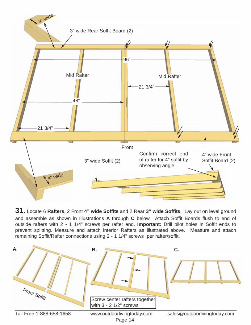
31. Locate 6 Rafters, 2 Front 4” wide Soffits and 2 Rear 3” wide Soffits. Lay out on level groundand assemble as shown in Illustrations A through C below. Attach Soffit Boards flush to end of outside rafters with 2 - 1 1/4” screws per rafter end. Important: Drill pilot holes in Soffit ends to prevent splitting. Measure and attach interior Rafters as illustrated above. Measure and attachremaining Soffit/Rafter connections using 2 - 1 1/4” screws per rafter/soffit.
4” wide
3” wide
3” wide Rear Soffit Board (2)
4” wide FrontSoffit Board (2)
48”
21 3/4”
21 3/4”
96”
A. B. C.
Front Soffit
Mid Rafter Mid Rafter
Front
3” wide Soffit (2)
Screw center rafters togetherwith 3 - 2 1/2” screws
Confirm correct end of rafter for 4” soffit byobserving angle.
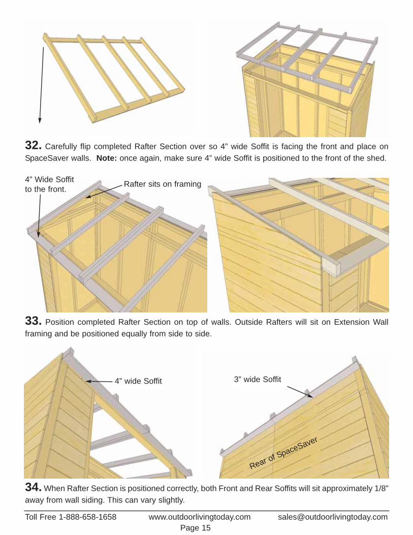
32. Carefully flip completed Rafter Section over so 4” wide Soffit is facing the front and place onSpaceSaver walls. Note: once again, make sure 4” wide Soffit is positioned to the front of the shed.
3” wide Soffit4” wide Soffit
Rear of SpaceSaver
Toll Free 1-888-658-1658 www.outdoorlivingtoday.com [email protected] 15
Rafter sits on framing4” Wide Soffitto the front.
33. Position completed Rafter Section on top of walls. Outside Rafters will sit on Extension Wall framing and be positioned equally from side to side.
34. When Rafter Section is positioned correctly, both Front and Rear Soffits will sit approximately 1/8”away from wall siding. This can vary slightly.
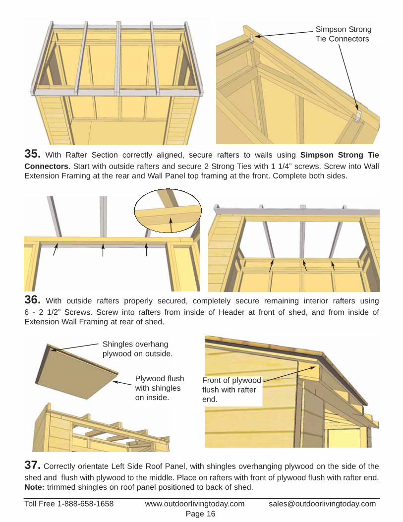
35. With Rafter Section correctly aligned, secure rafters to walls using Simpson Strong TieConnectors. Start with outside rafters and secure 2 Strong Ties with 1 1/4” screws. Screw into WallExtension Framing at the rear and Wall Panel top framing at the front. Complete both sides.
Simpson StrongTie Connectors
37. Correctly orientate Left Side Roof Panel, with shingles overhanging plywood on the side of theshed and flush with plywood to the middle. Place on rafters with front of plywood flush with rafter end.Note: trimmed shingles on roof panel positioned to back of shed.
Shingles overhangplywood on outside.
Front of plywoodflush with rafterend.
Plywood flushwith shingleson inside.
Toll Free 1-888-658-1658 www.outdoorlivingtoday.com [email protected] 16
36. With outside rafters properly secured, completely secure remaining interior rafters using 6 - 2 1/2” Screws. Screw into rafters from inside of Header at front of shed, and from inside ofExtension Wall Framing at rear of shed.

Attach abovethe exposureline.
40. Roof Filler Shingles are included to cover roof seams. Starting at the bottom, slide the first Longshingle in until flush with other bottom shingles. Screw first filler shingle down to rafters using 1 - 2 1/2” screw per panel (2 in total). Screw on slight angle and make sure to screw into rafter.
38. For correct Roof Panel position, align panel so plywood sits evenly on Center Rafters. Completeboth roof Panels.
Roof Seam
ExposureLine
Roof Panel centered onrafter.
39. With Roof Panels aligned, screw panels down to center rafters with 2 - 2 1/2” screws in BottomRow of Shingles Only (1 screw per panel).
Toll Free 1-888-658-1658 www.outdoorlivingtoday.com [email protected] 17
Screw BottomRow of ShinglesOnly for now.
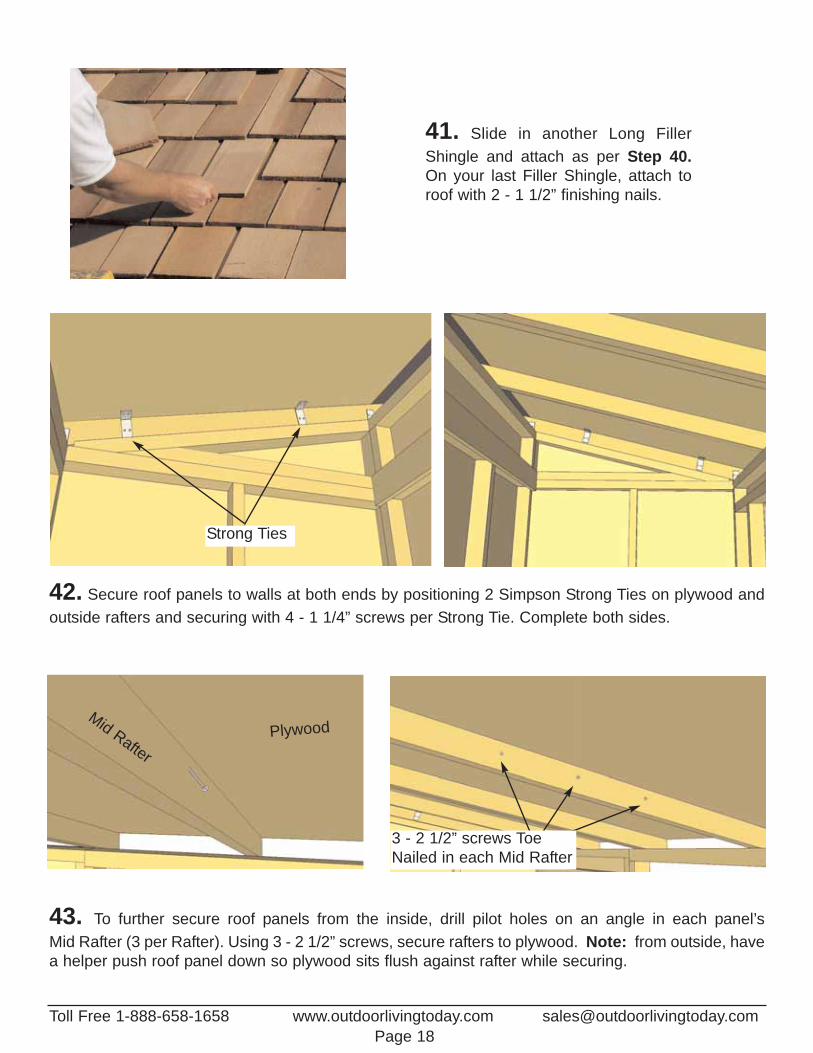
41. Slide in another Long FillerShingle and attach as per Step 40.On your last Filler Shingle, attach toroof with 2 - 1 1/2” finishing nails.
42. Secure roof panels to walls at both ends by positioning 2 Simpson Strong Ties on plywood and outside rafters and securing with 4 - 1 1/4” screws per Strong Tie. Complete both sides.
Strong Ties
43. To further secure roof panels from the inside, drill pilot holes on an angle in each panel’s Mid Rafter (3 per Rafter). Using 3 - 2 1/2” screws, secure rafters to plywood. Note: from outside, have a helper push roof panel down so plywood sits flush against rafter while securing.
Mid RafterPlywood
3 - 2 1/2” screws ToeNailed in each Mid Rafter
Toll Free 1-888-658-1658 www.outdoorlivingtoday.com [email protected] 18
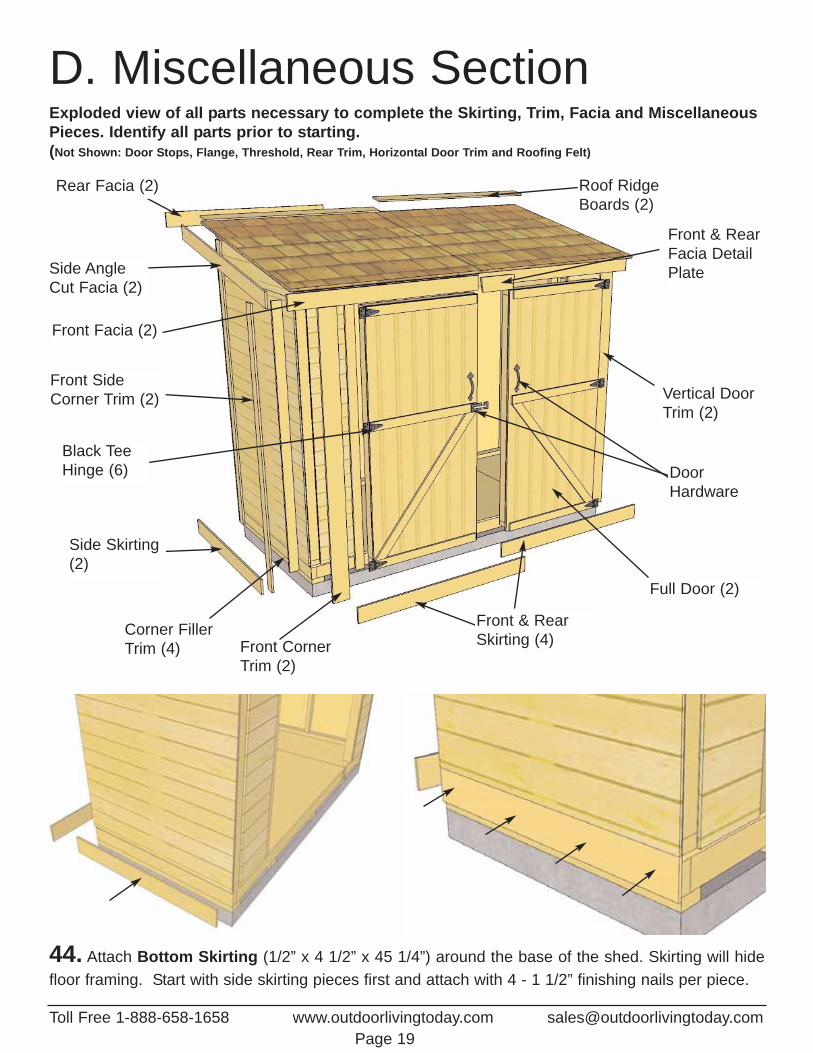
D. Miscellaneous SectionExploded view of all parts necessary to complete the Skirting, Trim, Facia and MiscellaneousPieces. Identify all parts prior to starting. (Not Shown: Door Stops, Flange, Threshold, Rear Trim, Horizontal Door Trim and Roofing Felt)
Rear Facia (2) Roof Ridge Boards (2)
Side Skirting(2)
Side Angle Cut Facia (2)
Front SideCorner Trim (2)
Front CornerTrim (2)
Corner FillerTrim (4)
Front & RearSkirting (4)
Full Door (2)
Black TeeHinge (6) Door
Hardware
Vertical DoorTrim (2)
Front & RearFacia Detail Plate
Front Facia (2)
44. Attach Bottom Skirting (1/2” x 4 1/2” x 45 1/4”) around the base of the shed. Skirting will hidefloor framing. Start with side skirting pieces first and attach with 4 - 1 1/2” finishing nails per piece.
Toll Free 1-888-658-1658 www.outdoorlivingtoday.com [email protected] 19
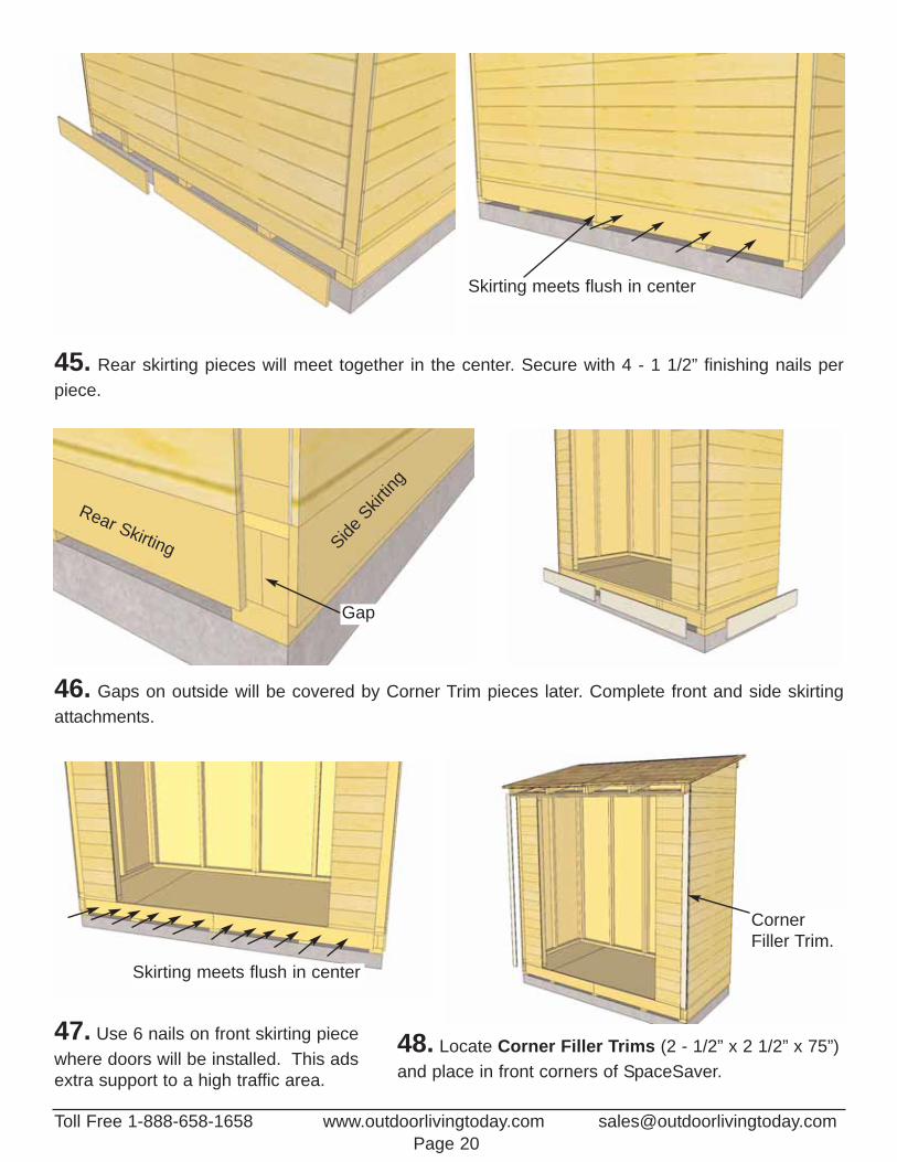
45. Rear skirting pieces will meet together in the center. Secure with 4 - 1 1/2” finishing nails perpiece.
46. Gaps on outside will be covered by Corner Trim pieces later. Complete front and side skirtingattachments.
48. Locate Corner Filler Trims (2 - 1/2” x 2 1/2” x 75”)and place in front corners of SpaceSaver.
Rear Skirting
Gap
SideSkir
ting
Skirting meets flush in center
CornerFiller Trim.
Toll Free 1-888-658-1658 www.outdoorlivingtoday.com [email protected] 20
Skirting meets flush in center
47. Use 6 nails on front skirting piecewhere doors will be installed. This adsextra support to a high traffic area.
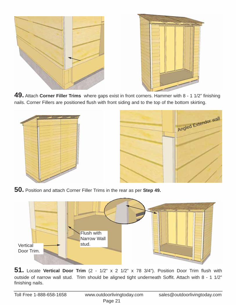
49. Attach Corner Filler Trims where gaps exist in front corners. Hammer with 8 - 1 1/2” finishingnails. Corner Fillers are positioned flush with front siding and to the top of the bottom skirting.
50. Position and attach Corner Filler Trims in the rear as per Step 49.
51. Locate Vertical Door Trim (2 - 1/2” x 2 1/2” x 78 3/4”). Position Door Trim flush with outside of narrow wall stud. Trim should be aligned tight underneath Soffit. Attach with 8 - 1 1/2” finishing nails.
Flush withNarrow Wallstud.Vertical
Door Trim.
Toll Free 1-888-658-1658 www.outdoorlivingtoday.com [email protected] 21
Angled Extendor wall
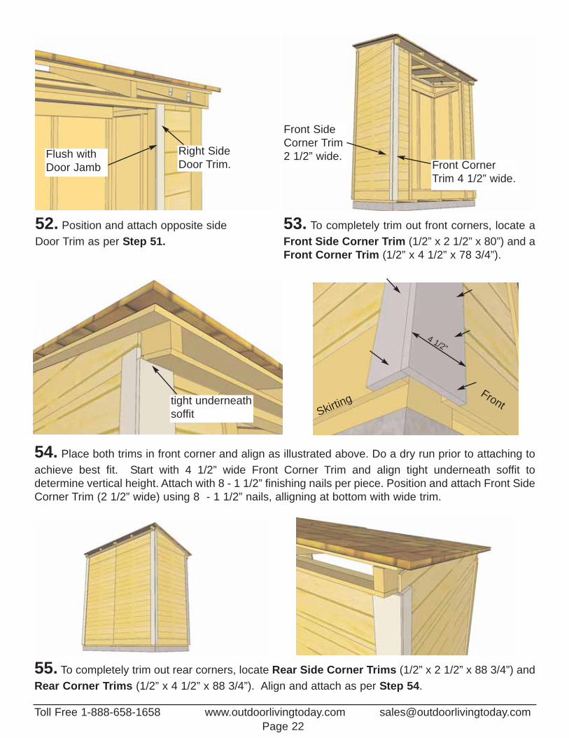
52. Position and attach opposite sideDoor Trim as per Step 51.
54. Place both trims in front corner and align as illustrated above. Do a dry run prior to attaching toachieve best fit. Start with 4 1/2” wide Front Corner Trim and align tight underneath soffit to determine vertical height. Attach with 8 - 1 1/2” finishing nails per piece. Position and attach Front SideCorner Trim (2 1/2” wide) using 8 - 1 1/2” nails, alligning at bottom with wide trim.
4 1/2”
Skirting
55. To completely trim out rear corners, locate Rear Side Corner Trims (1/2” x 2 1/2” x 88 3/4”) andRear Corner Trims (1/2” x 4 1/2” x 88 3/4”). Align and attach as per Step 54.
Right SideDoor Trim.
Flush withDoor Jamb
Toll Free 1-888-658-1658 www.outdoorlivingtoday.com [email protected] 22
53. To completely trim out front corners, locate a Front Side Corner Trim (1/2” x 2 1/2” x 80”) and aFront Corner Trim (1/2” x 4 1/2” x 78 3/4”).
Front SideCorner Trim2 1/2” wide.
Front CornerTrim 4 1/2” wide.
tight underneathsoffit
Front
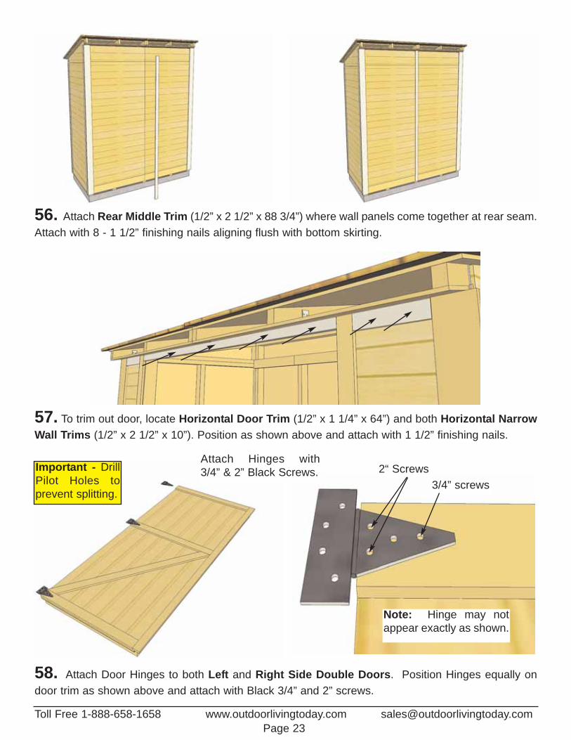
56. Attach Rear Middle Trim (1/2” x 2 1/2” x 88 3/4”) where wall panels come together at rear seam.Attach with 8 - 1 1/2” finishing nails aligning flush with bottom skirting.
Attach Hinges with 3/4” & 2” Black Screws.
Note: Hinge may notappear exactly as shown.
3/4” screws2“ Screws
58. Attach Door Hinges to both Left and Right Side Double Doors. Position Hinges equally ondoor trim as shown above and attach with Black 3/4” and 2” screws.
Important - DrillPilot Holes to prevent splitting.
57. To trim out door, locate Horizontal Door Trim (1/2” x 1 1/4” x 64”) and both Horizontal NarrowWall Trims (1/2” x 2 1/2” x 10”). Position as shown above and attach with 1 1/2” finishing nails.
Toll Free 1-888-658-1658 www.outdoorlivingtoday.com [email protected] 23
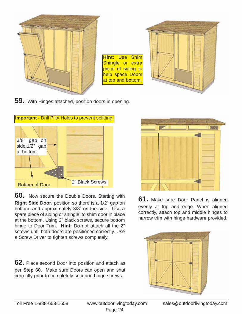
61. Make sure Door Panel is alignedevenly at top and edge. When aligned correctly, attach top and middle hinges tonarrow trim with hinge hardware provided.
62. Place second Door into position and attach asper Step 60. Make sure Doors can open and shutcorrectly prior to completely securing hinge screws.
60. Now secure the Double Doors. Starting withRight Side Door, position so there is a 1/2” gap onbottom, and approximately 3/8” on the side. Use aspare piece of siding or shingle to shim door in placeat the bottom. Using 2” black screws, secure bottomhinge to Door Trim. Hint: Do not attach all the 2”screws until both doors are positioned correctly. Usea Screw Driver to tighten screws completely.
Bottom of Door
3/8” gap onside,1/2” gapat bottom.
2” Black Screws
Important - Drill Pilot Holes to prevent splitting.
59. With Hinges attached, position doors in opening.
Toll Free 1-888-658-1658 www.outdoorlivingtoday.com [email protected] 24
Hint: Use ShimShingle or extrapiece of siding tohelp space Doorsat top and bottom.
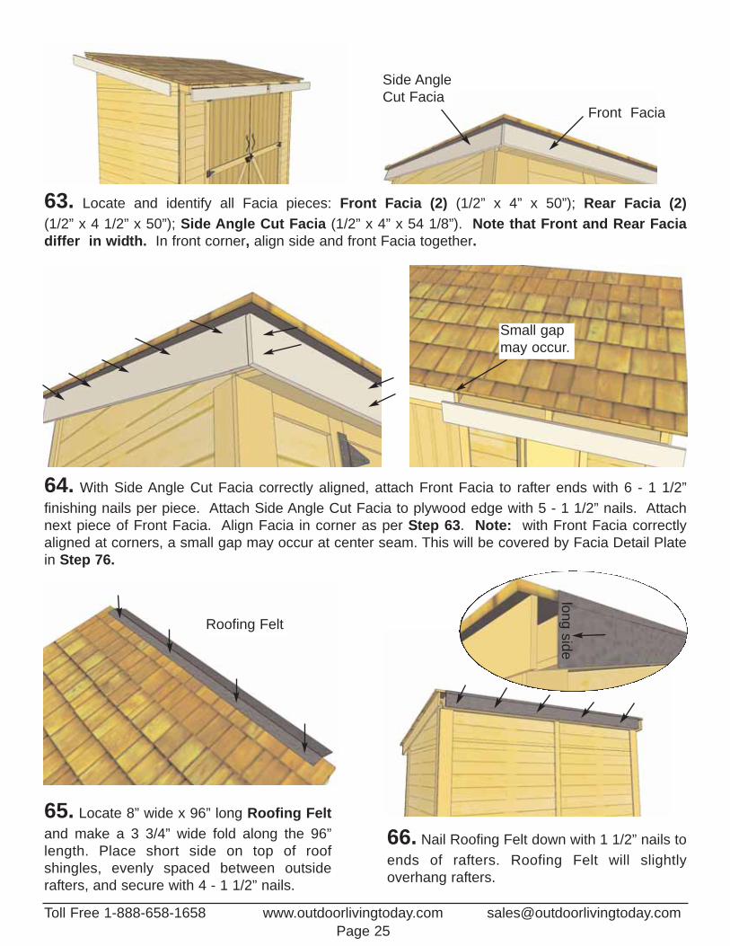
Front Facia
Side Angle Cut Facia
Toll Free 1-888-658-1658 www.outdoorlivingtoday.com [email protected] 25
64. With Side Angle Cut Facia correctly aligned, attach Front Facia to rafter ends with 6 - 1 1/2” finishing nails per piece. Attach Side Angle Cut Facia to plywood edge with 5 - 1 1/2” nails. Attachnext piece of Front Facia. Align Facia in corner as per Step 63. Note: with Front Facia correctlyaligned at corners, a small gap may occur at center seam. This will be covered by Facia Detail Platein Step 76.
Roofing Felt
65. Locate 8” wide x 96” long Roofing Feltand make a 3 3/4” wide fold along the 96”length. Place short side on top of roof shingles, evenly spaced between outsiderafters, and secure with 4 - 1 1/2” nails.
66. Nail Roofing Felt down with 1 1/2” nails toends of rafters. Roofing Felt will slightly overhang rafters.
Small gapmay occur.
longside
63. Locate and identify all Facia pieces: Front Facia (2) (1/2” x 4” x 50”); Rear Facia (2)(1/2” x 4 1/2” x 50”); Side Angle Cut Facia (1/2” x 4” x 54 1/8”). Note that Front and Rear Facia differ in width. In front corner, align side and front Facia together.

68. Position first Roof Ridge Board (1/2” x 4” x 51 5/8”) at the rear of roof to cap off shingles andfacia. Ridge Boards should meet on seam of roof panels. Ridge Boards should also completely coverRoofing Felt. When aligned correctly, attach with 4 - 1 1/2” nails.
67. Locate Rear Facia (1/2” x 4 1/2” x 50”) and align with top edge of roof shingles. Attach facia torafter ends with 6 - 1 1/2” finishing nails per piece. Complete both Rear Facia pieces.
Rear Facia alignedwith top of roof.
Ridge Board caps Rear Facia.
69. Align and attach remainingRoof Ridge Board as per Step 68.
Toll Free 1-888-658-1658 www.outdoorlivingtoday.com [email protected] 26
Toll Free 1-888-658-1658 www.outdoorlivingtoday.com [email protected] 27
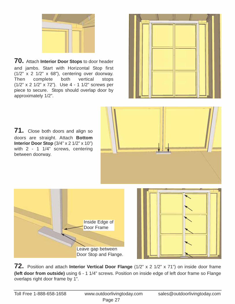
70. Attach Interior Door Stops to door headerand jambs. Start with Horizontal Stop first (1/2” x 2 1/2” x 68”), centering over doorway.Then complete both vertical stops (1/2” x 2 1/2” x 72”). Use 4 - 1 1/2” screws perpiece to secure. Stops should overlap door byapproximately 1/2”.
71. Close both doors and align sodoors are straight. Attach BottomInterior Door Stop (3/4” x 2 1/2” x 10”)with 2 - 1 1/4” screws, centeringbetween doorway.
72. Position and attach Interior Vertical Door Flange (1/2” x 2 1/2” x 71”) on inside door frame (left door from outside) using 6 - 1 1/4” screws. Position on inside edge of left door frame so Flangeoverlaps right door frame by 1”.
Inside Edge ofDoor Frame
Leave gap betweenDoor Stop and Flange.
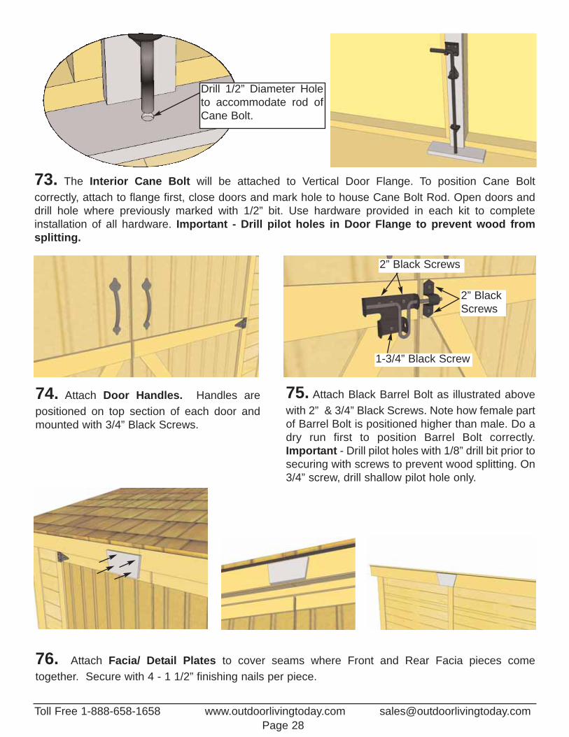
76. Attach Facia/ Detail Plates to cover seams where Front and Rear Facia pieces come together. Secure with 4 - 1 1/2” finishing nails per piece.
74. Attach Door Handles. Handles are positioned on top section of each door andmounted with 3/4” Black Screws.
75. Attach Black Barrel Bolt as illustrated abovewith 2” & 3/4” Black Screws. Note how female partof Barrel Bolt is positioned higher than male. Do adry run first to position Barrel Bolt correctly.Important - Drill pilot holes with 1/8” drill bit prior tosecuring with screws to prevent wood splitting. On3/4” screw, drill shallow pilot hole only.
73. The Interior Cane Bolt will be attached to Vertical Door Flange. To position Cane Bolt correctly, attach to flange first, close doors and mark hole to house Cane Bolt Rod. Open doors anddrill hole where previously marked with 1/2” bit. Use hardware provided in each kit to complete installation of all hardware. Important - Drill pilot holes in Door Flange to prevent wood from splitting.
2” BlackScrews
2” Black Screws
1-3/4” Black Screw
Toll Free 1-888-658-1658 www.outdoorlivingtoday.com [email protected] 28
Drill 1/2” Diameter Holeto accommodate rod ofCane Bolt.
Page 29
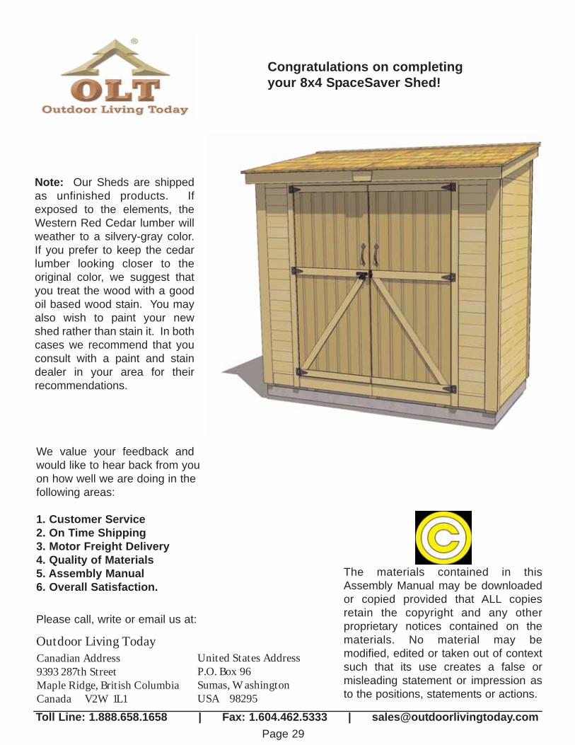
Note: Our Sheds are shippedas unfinished products. Ifexposed to the elements, theWestern Red Cedar lumber willweather to a silvery-gray color. If you prefer to keep the cedarlumber looking closer to theoriginal color, we suggest thatyou treat the wood with a goodoil based wood stain. You mayalso wish to paint your newshed rather than stain it. In bothcases we recommend that youconsult with a paint and staindealer in your area for their recommendations.
We value your feedback andwould like to hear back from youon how well we are doing in thefollowing areas:
1. Customer Service2. On Time Shipping3. Motor Freight Delivery4. Quality of Materials5. Assembly Manual6. Overall Satisfaction.
The materials contained in thisAssembly Manual may be downloadedor copied provided that ALL copiesretain the copyright and any other proprietary notices contained on thematerials. No material may be modified, edited or taken out of contextsuch that its use creates a false or misleading statement or impression asto the positions, statements or actions.
Canadian Address9393 287th StreetMaple Ridge, British ColumbiaCanada V2W 1L1
United States AddressP.O. Box 96Sumas, WashingtonUSA 98295
Outdoor Living Today
Please call, write or email us at:
Toll Line: 1.888.658.1658 | Fax: 1.604.462.5333 | [email protected]
Congratulations on completingyour 8x4 SpaceSaver Shed!
Related Documents