Item No. 24179 NACE International Publication 8X194 (2006 Edition) This Technical Committee Report has been prepared by NACE International Task Group 301* on Refinery H 2 S Pressure Vessels: Revision of NACE Publication 8X194: Report Materials and Fabrication Practices for New Pressure Vessels Used in Wet H 2 S Refinery Service © December 2006, NACE International This NACE International (NACE) technical committee report represents a consensus of those individual members who have reviewed this document, its scope, and provisions. Its acceptance does not in any respect preclude anyone from manufacturing, marketing, purchasing, or using products, processes, or procedures not included in this report. Nothing contained in this NACE report is to be construed as granting any right, by implication or otherwise, to manufacture, sell, or use in connection with any method, apparatus, or product covered by Letters Patent, or as indemnifying or protecting anyone against liability for infringement of Letters Patent. This report should in no way be interpreted as a restriction on the use of better procedures or materials not discussed herein. Neither is this report intended to apply in all cases relating to the subject. Unpredictable circumstances may negate the usefulness of this report in specific instances. NACE assumes no responsibility for the interpretation or use of this report by other parties. Users of this NACE report are responsible for reviewing appropriate health, safety, environmental, and regulatory documents and for determining their applicability in relation to this report prior to its use. This NACE report may not necessarily address all potential health and safety problems or environmental hazards associated with the use of materials, equipment, and/or operations detailed or referred to within this report. Users of this NACE report are also responsible for establishing appropriate health, safety, and environmental protection practices, in consultation with appropriate regulatory authorities if necessary, to achieve compliance with any existing applicable regulatory requirements prior to the use of this report. CAUTIONARY NOTICE: The user is cautioned to obtain the latest edition of this report. NACE reports are subject to periodic review, and may be revised or withdrawn at any time without prior notice. NACE reports are automatically withdrawn if more than 10 years old. Purchasers of NACE reports may receive current information on all NACE International publications by contacting the NACE FirstService Department, 1440 South Creek Drive, Houston, Texas 77084-4906 (telephone +1 281/228-6200). FOREWORD The objective of this technical committee report is to provide a state-of-the-art overview of the materials selection, fabrication, postweld heat treatment (PWHT), inspection, and testing practices that have recently been applied to new pressure vessels (referred to in this report as equipment) destined for use in wet hydrogen sulfide (H2S) refinery service. This report is intended as a technical resource for material manufacturers, fabricators, and users involved in the specification and fabrication of new equipment used in wet H2S refinery services. Many of the practices discussed in this report were identified in informal industry surveys of refiners, process licensors, and engineering contractors conducted in 1991 by NACE Work Group (WG) T-8-16g and in 2004 by NACE Task Group (TG) 301. This information has been supplemented by the experiences of the work group and task group members and their colleagues. In this report the term “user” refers to the end user of the equipment, i.e., refiners or engineering contractors acting on behalf of refiners during equipment design, purchase, and installation. This report makes extensive use of the terms “some users,” “many users,” and “most users.” These terms were adopted by the work group and task group to give a qualitative feel to the types of user responses received in the informal surveys and follow-up user comments received during the preparation of the report. There is no accurate quantitative correlation between these terms and the actual responses and comments received other than that the progression from “some” to “most” indicates, in the opinion of the task group, a trend from the minority to the majority of users. The titles and source information of the codes, specifications, and standards cited or discussed in ___________________________ *Chair Terrell T. Phillips, Fluor Corporation, Sugar Land, Texas.

Welcome message from author
This document is posted to help you gain knowledge. Please leave a comment to let me know what you think about it! Share it to your friends and learn new things together.
Transcript

Item No. 24179 NACE International Publication 8X194 (2006 Edition) This Technical Committee Report has been prepared by NACE International Task Group 301* on Refinery H2S Pressure Vessels: Revision of NACE Publication 8X194: Report
Materials and Fabrication Practices for New Pressure Vessels Used in Wet H2S Refinery Service
© December 2006, NACE International
This NACE International (NACE) technical committee report represents a consensus of those individual members who have reviewed this document, its scope, and provisions. Its acceptance does not in any respect preclude anyone from manufacturing, marketing, purchasing, or using products, processes, or procedures not included in this report. Nothing contained in this NACE report is to be construed as granting any right, by implication or otherwise, to manufacture, sell, or use in connection with any method, apparatus, or product covered by Letters Patent, or as indemnifying or protecting anyone against liability for infringement of Letters Patent. This report should in no way be interpreted as a restriction on the use of better procedures or materials not discussed herein. Neither is this report intended to apply in all cases relating to the subject. Unpredictable circumstances may negate the usefulness of this report in specific instances. NACE assumes no responsibility for the interpretation or use of this report by other parties. Users of this NACE report are responsible for reviewing appropriate health, safety, environmental, and regulatory documents and for determining their applicability in relation to this report prior to its use. This NACE report may not necessarily address all potential health and safety problems or environmental hazards associated with the use of materials, equipment, and/or operations detailed or referred to within this report. Users of this NACE report are also responsible for establishing appropriate health, safety, and environmental protection practices, in consultation with appropriate regulatory authorities if necessary, to achieve compliance with any existing applicable regulatory requirements prior to the use of this report. CAUTIONARY NOTICE: The user is cautioned to obtain the latest edition of this report. NACE reports are subject to periodic review, and may be revised or withdrawn at any time without prior notice. NACE reports are automatically withdrawn if more than 10 years old. Purchasers of NACE reports may receive current information on all NACE International publications by contacting the NACE FirstService Department, 1440 South Creek Drive, Houston, Texas 77084-4906 (telephone +1 281/228-6200).
___________________________*Chair Terrell T. Phillips, Fluor Corporation, Sugar Land, Texas.
FOREWORD
The objective of this technical committee report is to provide a state-of-the-art overview of the materials selection, fabrication, postweld heat treatment (PWHT), inspection, and testing practices that have recently been applied to new pressure vessels (referred to in this report as equipment) destined for use in wet hydrogen sulfide (H2S) refinery service. This report is intended as a technical resource for material manufacturers, fabricators, and users involved in the specification and fabrication of new equipment used in wet H2S refinery services. Many of the practices discussed in this report were identified in informal industry surveys of refiners, process licensors, and engineering contractors conducted in 1991 by NACE Work Group (WG) T-8-16g and in 2004 by NACE Task Group (TG) 301. This information has been supplemented by the experiences of the work group and task group members and their colleagues.In this report the term “user” refers to the end user of the equipment, i.e., refiners or engineering contractors acting on behalf of refiners during equipment design, purchase, and installation. This report makes extensive use of the terms “some users,” “many users,” and “most users.” These terms were adopted by the work group and task group to give a qualitative feel to the types of user responses received in the informal surveys and follow-up user comments received during the preparation of the report. There is no accurate quantitative correlation between these terms and the actual responses and comments received other than that the progression from “some” to “most” indicates, in the opinion of the task group, a trend from the minority to the majority of users. The titles and source information of the codes, specifications, and standards cited or discussed in

NACE International NACE International
this report or the appendixes are provided in Appendix A rather than listed in footnotes throughout the report. Confining this important source document information to one appendix should help readers who have any interest in further research. The intent of the practices reviewed in this report has been to minimize the susceptibility to several forms of low-temperature (ambient to 150°C [300°F]) hydrogen damage that have occurred when fabricated carbon steel (CS) equipment has been exposed to corrosive refinery environments containing wet H2S. These damage mechanisms have been reported to include sulfide stress cracking (SSC), hydrogen blistering, hydrogen-induced cracking (HIC), and stress-oriented hydrogen-induced cracking (SOHIC).1 Background information on refining industry practices that have been used to prevent SSC of hard welds is provided in NACE Standard RP0472, which was developed in response to a number of SSC failures that occurred in hard weld deposits in CS equipment in the late 1960s. In addition, a form of alkaline stress corrosion cracking (ASCC) commonly referred to as “carbonate cracking” has been identified in some wet H2S environments, mainly overhead streams in fluid catalytic cracking units (FCCUs) and some process water-handling equipment.1,2,3 ASCC damage mechanisms are not covered in this report, but are defined and discussed, along with SCC, hydrogen blistering, HIC, and SOHIC, in NACE Standard RP0296. Also, Appendix A of American Petroleum Institute (API) RP 945 provides a concise overview of the cracking mechanisms, including figures showing typical crack morphologies. From the 1991 and 2004 informal surveys, it was determined that many users have selectively specified materials, fabrication, inspection, and testing practices for new equipment after considering and evaluating some of the following factors:
• Experience with similar equipment; • Type of process unit involved; • Type of equipment involved; • Process environment, including but not limited to: • Total sulfide concentration in the aqueous phase; • Potential for hydrogen activity; • pH value of aqueous phase; • Cyanide concentration in aqueous phase; • CO2 (carbonate) concentration in aqueous phase; • Ammonium bisulfide concentration in aqueous
phase; • Amount of aqueous phase; • Temperature; • Pressure; and • Upset, start-up, and shut-down conditions,
including steamout. • Corrosion control program to be used; • Future inspection requirements; • Life-cycle cost; and
3
2
• Safety and economic risk based on consequence and probability of failure.
It is beyond the scope of this report, and available industry experience, to fully address all of these factors and their impact on the materials of construction and fabrication practices that have been used for new equipment; therefore, for the purpose of this report, TG 301 has developed a simplified scheme by creating three general categories of service. This approach is further described in the section of the report titled Categories of Service. Many of the practices reviewed and discussed in this report, particularly the use of special clean steel plate materials in severe refinery environments, have been shown to have mixed success by extensive plant experience; therefore, even with the use of these practices, damage to CS equipment in severe wet H2S environments continues to be a concern for users. Some refineries have had some degree of success in mitigating the effects of wet H2S environments on CS equipment by the use of water washing, polysulfide injection, or corrosion inhibitors. Some experiences when using such methods are reviewed and discussed in Appendix B. One established method of preventing damage in wet H2S environments has been the use of corrosion-resistant alloy cladding or weld overlay. The experiences and benefits of these methods are reviewed and discussed in Appendix C. Appendix C also includes information on the use of other types of liners such as organic thin-film coatings, cement linings, and thermal spray coatings. These types of liners have been used for the protection of previously operated equipment but have generally not been used for new construction. Most users have used a corrosion-resistant alloy cladding or weld overlay when a liner has been specified. Appendix D contains comparative equipment costs for different materials of construction used in wet H2S service. A significant percentage of the problems found during in-service inspection of CS equipment in wet H2S environments has been found to be the direct or indirect result of pre-existing fabrication flaws. Many of the practices reviewed and discussed in this report have been specified by users to improve the overall quality of fabrication. By employing these practices, users have attempted to reduce the extent and frequency of in-service inspections, make inspection results easier to interpret, and reduce the overall costs associated with performing inspections and making repairs. This report was originally prepared by WG T-8-16g, a component of TG T-8-16 on Cracking in Wet H2S Environments. It was revised in 2006 by TG 301 on Refinery Wet H2S Pressure Vessels: Revision of NACE
NACE International NACE International
Publication 8X194. TG 301 is sponsored administratively by Specific Technology Group (STG) 34 on Petroleum Refining and Gas Processing and sponsored by STG 32 on Oil and Gas Production—Metallurgy. This report is
3
published by NACE under the auspices of STG 34. It is one of many committee activities that have been sponsored by STG 34 related to the general problem of cracking of CS equipment in wet H2S refinery services.
NACE technical committee reports are intended to convey technical information or state-of-the-art knowledge regarding corrosion. In many cases, they discuss specific applications of corrosion mitigation technology, whether considered successful or not. Statements used to convey this information are factual and are provided to the reader as input and guidance for consideration when applying this technology in the future. However, these statements are not intended to be recommendations for general application of this technology, and must not be construed as such.
INTRODUCTION
This report reviews and discusses materials selection, fabrication, PWHT, inspection, testing, and corrosion control practices that have been used for recently manufactured new equipment destined for use in wet H2S refinery environments. Some users choose to take a risk-based assessment approach to the application of the followingservice categories to new equipment using individual plant operating experience when available. For the purpose of this report, it has been assumed that the equipment was designed and built to the ASME Boiler and Pressure Vessel Code (BPVC), Section VIII, Division 1 or Division 2. Piping and atmospheric storage tanks are excluded from the scope of this report.
RISK-BASED ASSESSMENT
Risk-based principles have been used to help users make decisions concerning materials selection and fabrication practices for equipment. Evaluation of risk has used industry standard approaches such as those found in API RP 580 and API Publication 581 or similar procedures and methodologies unique to the user. In either case, the risk assessment process addresses the likelihood of cracking and the consequence of failure. Materials selection options evaluated have included whether to use steels with special chemistry controls such as carbon equivalent (CE) and microalloy limits to specify HIC-resistant steel, or to use stainless steel (SS) cladding or solid SS (duplex SS or UNS(1) S30000 series [300 series] SS) equipment. Fabrication decisions have included whether special welding procedures addressing preheat, heat input, and/or other factors are used, whether and at what conditions to postweld heat treat equipment, and whether 100% weld inspection is performed to help determine whether fabrication flaws are present prior to placing equipment in service. Several factors have been considered in assessing the probability of low-temperature hydrogen damage of equipment exposed to wet H2S service. The severity of
the environment (e.g., the expected level of H2S or NH4HS) and the presence of other crack-promoting agents (e.g., cyanides) are significant factors considered by most users. The strength of material specified has also been considered. For example, some users assign a lower likelihood of cracking to a lower-strength material (e.g., 414 MPa [60,000 psi] tensile strength) than to a higher-strength material (e.g., 482 MPa [70, 000 psi] tensile strength). Another factor is the experience in the exposure environment of existing equipment when replacing or revamping existing units. Finally, whether PWHT of the equipment has or will be used is a factor considered by most users. Operating environments change with time because of changes in feed stock, debottlenecking, temperature changes, etc. The concentration of H2S where vapor streams first come into contact with water is also considered by most users. Stream conditions are typically analyzed and risk assessments reevaluated as these environments change during equipment operating lives.
___________________________ (1) Metals and Alloys in the Unified Numbering System, a joint publication of ASTM International (ASTM), 100 Barr Harbor Drive, West Conshohocken, PA 19428-2959, and SAE International (SAE), 400 Commonwealth Drive, Warrendale, PA 15096-0001.

NACE International
NACE International
CATEGORIES OF SERVICE
Background Generally, when specifying materials and fabrication practices for new equipment, most users have classified refinery process environments in which the concentration of total sulfide is greater than 50 ppmw in the aqueous phase as wet H2S service. In addition, some users have reported applying some of the practices discussed in this report to process environments with lower concentrations of total sulfide, specifically in cases in which experience has shown wet H2S cracking or blistering to have occurred in equipment exposed to a comparable process environment or operated under comparable upset, start-up, or shut-down conditions. Industry survey results have not established a concentration of H2S below which cracking or blistering problems have not occurred. In the absence of operating experience or more relevant information, Figures 1 and 2 of NACE Standard MR0175/ISO 15156 have sometimes been used as a guideline on process environments that could cause SSC. Petrie and Moore4 provide examples of this approach. Additional guidance regarding susceptibility to SCC in refining services is also contained in NACE Standard MR0103. Several methods are used to estimate the H2S concentration in the aqueous phase. In existing plants, actual measurements of H2S (and other contaminants) in condensed waters are used to evaluate severity of exposure. Petrie and Moore describe one method based on Henry's Law, and Newman5 provides an easy graphical method for a wide range of temperatures and concentrations of ammonia (NH3). For the purpose of this report, three general categories of refinery wet H2S service are outlined. These categories were developed from reported user experiences and practices, along with a fundamental understanding of the cracking mechanisms experienced in the process service or environment. Category 1 service has been used in the report to represent a low potential, Category 2 service a moderate potential, and Category 3 service a high potential for low-temperature hydrogen damage in wet H2S refinery environments. These three categories are used in this report to differentiate between practices that have been applied by some users, based on process environment or service, type of equipment, or history. Some equipment known to contain wet H2S are found in crude and vacuum distillation units, FCCU fractionation and light ends recovery sections, delayed coking unit (DCU) fractionation and light ends recovery sections, hydroprocessing unit separation and fractionation sections, sour water stripper overhead systems, and amine unit regenerator and contactor systems. Equipment examples4
are wetted sections of drums, heat exchanger shells, and air cooler header boxes, including heads and vapor sections in the condensing zone, and equipment or sections of equipment where an aqueous phase may or could accumulate. Category 1 Service New CS equipment in Category 1 service has been regarded by most users to present a low potential for SSC in weld heat-affected zones (HAZs) and negligible potential for SOHIC in weld HAZs or base metal HIC or blistering. Experience has shown that CS equipment used in this category of service has not been susceptible to severe wet H2S cracking or blistering problems. The principal damage to equipment in this category of service has been SSC as a result of hard HAZ microstructures or hard weld metal. Some users have also judged this category of service applicable to equipment or parts of equipment in more severe process environments that could be easily inspected and possibly repaired on a frequent basis without significant risk to plant safety or production. Some users have also judged this category of service applicable to some types of equipment provided with some protection from the process environment by water washing, polysulfide injection, the use of a corrosion inhibitor, or the application of a nonmetallic coating. These methods of mitigating the cracking potential of CS equipment in wet H2S environments are discussed further in Appendixes B and C. Users have characterized wet H2S Category 1 service in one or more of the following ways: Process Environment Some users have used the following process environments to characterize Category 1 service: Typically a process temperature between ambient and 150°C (300°F) and:
• Low or no potential for hydrogen flux activity as a result of aqueous corrosion;
• Aqueous phase with <50 ppmw total sulfide and near neutral pH (6.5 to 7.5);
• No known or measurable hydrogen cyanide (HCN) or other cyanide compounds (generally <20 ppmw in the aqueous phase);
• Processes in which experience has shown polysulfide injection or corrosion inhibitors to be effective in mitigating corrosion; or
• Conditions defined in API 581 for low-severity service.
NACE International NACE International
History • No SSC problems; and • No significant SOHIC, HIC, or blistering problems. Category 2 Service New CS equipment in Category 2 service has been regarded by most users as presenting a moderate potential for SSC, SOHIC, HIC, or blistering, based on the severity of the process environment. Experience has shown that CS equipment used in this category of service, built without the use of many of the practices discussed in this report, has experienced some base metal HIC or blistering problems and/or some SSC or SOHIC in weld HAZs. Some users have also judged this category of service applicable to equipment or parts of equipment in less severe process environments that would be physically difficult or costly to inspect and possibly repair, or equipment in which a cracking failure could pose a significant risk to plant safety or production. Some users have specified “clean steels” manufactured to improve resistance to blistering, HIC, and SOHIC for equipment plates used for pressure boundary components in this category of service. The use of these special “clean steels” is an effective solution to minimizing susceptibility to blistering, HIC, and SOHIC problems.6 However, these “clean steels” may be susceptible to SOHIC damage under certain conditions.7,8 Most users have not specified the use of special “clean steels” as a solution to SSC problems. Some user experience has shown that when CS equipment has been used in this category of service, mitigating or protective measures such as water washing, polysulfide injection, the use of a corrosion inhibitor, or the application of a nonmetallic coating have sometimes been incorporated to minimize corrosion and the potential for cracking and/or blistering. These practices are discussed further in Appendixes B and C. Appendix D contains comparative equipment costs for different materials of construction used in wet H2S service, including standard CS, special clean CS plate tested for resistance to HIC, and CS clad with austenitic SS. Users have characterized wet H2S Category 2 service in one or more of the following ways: Process Environment Some users have used the following process environments to characterize Category 2 service: Typically a process temperature between ambient and 150°C (300°F) and at least one of the following: • Moderate potential for hydrogen flux activity as a result
of aqueous corrosion, and an aqueous phase with >50
55
ppmw total sulfide; or • Greater than 0.0003 MPa (0.05 psia) partial pressure of
H2S in the gas phase, and an aqueous phase with <2,000 ppmw total sulfide and pH <4; or
• Aqueous phase with <2,000 ppmw total sulfide and pH >7.6, and HCN <20 ppmw; or
• Aqueous phase with >2 wt% NH4HS; or • Aqueous phase with 4 to 6 wt% NH4HS; or • Conditions defined in API 581 for moderate service. History • Equipment with some SSC, SOHIC, HIC, or blistering
problems or comparable equipment in a similar service with such problems.
Category 3 Service New CS equipment in Category 3 service has been regarded by most users as presenting a high potential for SSC, SOHIC, HIC, or blistering, based on the severity of the process environment. Experience has shown that CS equipment used in this category of service, built without the use of many of the practices discussed in this report, has experienced significant base-metal HIC or blistering problems and/or significant SSC or SOHIC in weld HAZs. Some users have also judged this category of service applicable to equipment or parts of equipment in less severe process environments that would be physically difficult or costly to inspect and possibly repair, or equipment in which a cracking failure could pose a significant risk to plant safety or production. Some users have specified special “clean steels” manufactured to improve resistance to blistering, HIC, and SOHIC for equipment plates used for pressure boundary components in this category of service. The use of these special “clean steels” is an effective solution to minimizing susceptibility to blistering, HIC, and SOHIC problems.6 However, these “clean steels” are often susceptible to SOHIC damage with process conditions that give high hydrogen charging rates.7,8 Most users have not specified the use of special “clean steels” as a solution to SSC problems. Some user experience has shown that when CS equipment has been used in this category of service, mitigating or protective measures such as water washing, polysulfide injection, the use of a corrosion inhibitor, or the application of a nonmetallic coating have sometimes been incorporated to minimize corrosion and the potential for cracking and/or blistering. These practices are discussed further in Appendixes B and C. For some applications in this category of service, some users have found it more effective and economical to use corrosion-resistant alloy cladding or weld overlay to avoid

NACE International NACE International
the costs associated with in-service inspections and repairs of CS equipment. This approach is discussed further in Appendix C. Appendix D contains comparative equipment costs for different materials of construction used in wet H2S service, including standard CS, special clean CS plate tested for resistance to HIC, and CS clad with austenitic SS. Users have characterized wet H2S Category 3 service in one or more of the following ways: Process Environment Some users have used the following process environments to characterize Category 3 Service: Typically a process temperature between ambient and 150°C (300°F) and at least one of the following:
6
6
High potential for hydrogen flux activity as a result of aqueous corrosion, and an aqueous phase with >50 ppmw total sulfide; or • Greater than 0.0003 MPa (0.05 psia) partial pressure of
H2S in the gas phase, and an aqueous phase with >2,000 ppmw total sulfide and pH <4; or
• Aqueous phase with >2,000 ppmw total sulfide, pH >7.6, and HCN >20 ppmw; or
• Aqueous phase with > 2 wt% NH4HS; or • Aqueous phase with > 6 wt% NH4HS; or • Conditions defined in API 581 for severe service. History Equipment with significant SSC, SOHIC, HIC, or blistering problems or comparable equipment in a similar service with such problems.
MATERIALS OF CONSTRUCTION
Background The purpose of this section of the report is to review chemistry and strength grade restrictions, heat-treatment conditions, inspection, and testing requirements that have been frequently specified by users for CS pressure-retaining components in wet H2S service. With the exception of heat-treatment condition and ultrasonic examination, many of the general practices described below have typically been used for pressure-retaining components in all categories of service. In addition, special “clean steel” plate manufactured to improve resistance to blistering, HIC, and SOHIC is described in the second subsection. Most users have indicated that standard ASME SA-516 plate material, supplied in accordance with the general practices given below, has provided satisfactory performance when used for equipment in Category 1 service. Some users have indicated that internally coated standard ASME SA-516 plate material and “HIC” ASME SA-516 plate material has provided satisfactory performance when used for equipment in Category 2 service. Some users have indicated that “HIC” ASME SA-516 plate material and standard ASME SA-516 plate material clad with UNS S30000 series SS in accordance with ASME SA-264 have provided satisfactory performance when used for equipment in Category 3 service.
General Practices Material Specifications for Equipment Fabrication Many users have utilized ASME material specifications that require the steel to be fully killed (except thin-wall heat exchanger tubing), that set specified limits on residual elements, and that allow user control of the CE as a supplementary requirement. Commonly used material specifications (by product form) that meet these criteria are as follows: • Plate: ASME SA-516 grade 55, 60, 65, or 70 • Pipe: ASME SA-106 grade B or ASME SA-333 grade 1
or 6 • Forgings: ASME SA-105 or ASME SA-350 grade LF1
or LF2 or ASME SA-266 class 1 • Fittings: ASME SA-234 grade WCB or ASME SA-420
grade WPL6 • Castings: ASME SA-216 grade WCA, WCB, or WCC
or ASME SA-352 grade LCA, LCB, or LCC • Tubing: ASME SA-179 or ASME SA-214 Some users have also specified that thin-wall heat exchanger tubing be supplied as fully killed steel. In such cases, ASME SA-210 grade A-1 has sometimes been used.

NACE International
Bolt Materials Many users have utilized ASME bolt materials with hardness controlled to 22 HRC (237 HBW) maximum for wetted internal low-alloy steel bolting directly exposed to wet H2S environments. Material specifications commonly used to meet this criterion are ASME SA-193 grade B7M or ASME SA-320 grade L7M. Alternatively, some users have specified bolt materials in accordance with NACE Standard MR0103. Chemical Analysis To verify steel chemistry and CE, many users have specified that welded CS pressure-retaining components be supplied with a Certified Material Test Report (CMTR). Many users have required that chemical analysis results, as reported on the CMTR, include the unspecified elements chromium (Cr), columbium (Cb) (also known as niobium [Nb]), nickel (Ni), vanadium (V), molybdenum (Mo), and copper (Cu). Most of these elements are required to calculate the CE. Limits on these unspecified elements are provided in the applicable ASME material specification. Many users have reported trying to specifically avoid the use of CS materials with deliberate additions of microalloying elements because of potential HAZ microstructure and hardness problems.(2)It has been shown that the effect of Cb and V on HAZ hardness is dependent on the carbon level in the steel and welding heat input. Pipeline steels with carbon <0.12 wt% can tolerate Cb or V ≤0.04 wt% with Cb + V = 0.07 wt% maximum. Some users specify pressure vessel plate steels with carbon >0.12 wt% to be limited to Cb ≤0.01 wt% or V ≤0.02 wt% with Cb + V ≤0.015 wt% to control HAZ hardness without PWHT.9,10 When Cb + V are present at higher levels in steels with carbon >0.12 wt%, PWHT at 635°C (1,175°F) for 2 h minimum of welds made with low heat input is specified by some users to reduce HAZ hardness below 248 HV10.10,11 Carbon Equivalent For welded components, many users have specified a controlled base material CE as one step in the control of the weld HAZ microstructure and hardness. However, a minimum CE is necessary to impart the minimum specified tensile strength to the base material. A commonly specified maximum CE value for CS pressure-
7
retaining components has been 0.43. For base metal hardenability, CE is commonly calculated using Equation (1):
5
VMoCr
15
CuNi
6
MnCCE
+++
+++= (1)
Note: Numerical values entered for the elements in Equation (1) are concentration in wt%. Ultrasonic Examination Some users specify an ultrasonic examination for standard ASME SA-516 plate material to provide baseline inspection data. This type of testing is described further in the next section addressing special clean steel plate. For steels that contain Cb + V >0.015 wt%, a few users use CE equations that also include a Cb factor.9
Data provided by a steelmaker12 shows that the use of a CE value less than or equal to 0.43 restricts the maximum thickness of ASME SA-516 grade 70 material that meets the minimum specified tensile strength in the PWHT condition. The steelmaker's data show that in order to meet the minimum specified tensile strength in thicker plates, use of SA-516 grade 70 material with a higher CE value or use of lower-strength material (e.g., SA-516 grades 60 or 65) are options available.13 One user has reported using a maximum CE value of 0.48 for plates thicker than 50 mm (2 in.). The same user has also reported that a maximum CE of 0.38 has been used for all plate thicknesses when the material has deliberate additions of microalloying elements (Cb + V <0.03 wt% or individual values >0.02 wt%).14
Strength Grade Some users have specified a maximum strength grade to be used for plate materials (e.g., ASME SA-516 grade 60). Some steelmakers have supplied steel plate certified to multiple strength grades on the same CMTR. Therefore, experience has shown that strength grade alone has not been a reliable control on the material purchased, unless additional requirements such as maximum tensile strength, maximum CE, or restrictions on the use of microalloying element additions have also been specified.
___________________________ (2) In sour oil and gas pipelines and flowlines there have been many successful applications of carbon steels containing deliberate additions of microalloying elements, e.g., Cb + V + titanium (Ti) <0.12 wt% with carbon <0.12 wt%. Generally, these steels have been thermomechanically control processed (controlled rolling with accelerated cooling) to produce a high yield strength and have been manufactured using clean-steel technology to produce resistance to HIC. Typically, these steels have had very low CE values and they have been welded with minimal preheat and no PWHT. Experience has shown that high HAZ hardness on the inside of the pipe has not been a problem, probably because of the low CE values and the tempering effect of the multipass single-sided welds used in pipe welding. Because of differences in process environments and fabrication practices, the use of microalloyed steels has generally not been embraced for refinery equipment.

NACE International
Heat-Treatment Condition A steelmaker reports15 that a heat treatment such as normalizing, normalizing and tempering, or quenching and tempering is beneficial when plate material with improved resistance to blistering, HIC, or SOHIC is required. Most users specify use of fully killed and normalized CS plate material in wet H2S service. Special Clean Steel Plate Background The resistance of CS plate to low-temperature hydrogen damage in the form of blistering, HIC, and SOHIC has been shown to be improved by special steelmaking techniques that reduce and modify nonmetallic inclusions present in steels. Many of these techniques were developed for oil and gas production “sour service” pipeline steels or for heavy-gauge steel plates where resistance to through-thickness lamellar tearing is required. Some of these specialized manufacturing techniques have included deoxidation practices to produce fully killed steels; reducing sulfur and phosphorous contents to very low levels; using specialized steelmaking methods such as ladle refining; vacuum degassing; inclusion shape control using elements such as calcium; ingot casting using bottom pouring and special hot-topping practices; continuous casting using special shrouding techniques; and cross-rolling practices for thinner plates. Application to Equipment Steels for Wet H2S Service At this time there is not a standard practice for the manufacture of special clean steel plate for refinery equipment applications in which resistance to blistering, HIC, or SOHIC is desired. From the informal industry surveys and subsequent follow-up discussions with users and steelmakers, it has been established that the most common practice at this time has been to use steel supplied to ASME SA-516 material specification, normalized, vacuum degassed with a maximum sulfur (S) content of 0.002 wt% and a maximum phosphorus (P) content of 0.010 wt%. Some steelmakers report adding inclusion shape-controlling elements;16 others do not, because they rely on very low sulfur contents to effectively eliminate the presence of manganese sulfide inclusions.17Testing for Resistance to Hydrogen-Induced Cracking NACE Standard TM0284 (low-pH Solution A) is the standard test method for evaluating the HIC resistance of special clean steel plate intended for wet H2S refinery applications. NACE Standard TM0284 test results are reported as crack length ratio (CLR), crack thickness ratio (CTR), and crack
8
sensitivity ratio (CSR). At this time, there is no known correlation between these test results and actual resistance to blistering, HIC, or SOHIC in wet H2S refinery environments. For many oil and gas production “sour service” pipeline applications, a maximum CLR value of up to 15% has been used as an acceptance standard. CTR and CSR values have typically been reported for information only. Steelmakers have produced and marketed equipment plate for wet H2S refinery applications with test values lower than:
CLR = 5.0% CTR = 1.5% CSR = 0.5%
Because the NACE Standard TM0284 test method was developed to cover relatively thin pipeline steels, difficulties have arisen during testing of equipment plates thicker than the 30-mm (1.2-in.) maximum thickness covered by NACE Standard TM0284. Because it has generally been regarded as important to sample material across the full plate thickness, additional test specimens have typically been specified. Most users have accepted a staggered approach to the location of the individual test specimens, thus using more than three test specimens only when the plate thickness exceeded 90 mm (3.5 in.). Some other users have specified a staggered approach, but included three test specimens from each 30-mm (1.2-in.) layer, thus using nine test specimens to cover a 90-mm (3.5-in.) plate thickness, and even more test specimens when the plate thickness exceeded 90 mm (3.5 in.). Steelmakers have reported that this approach has increased testing costs threefold. Many users have accepted test results on a heat/thickness basis. Some users have specified per-plate tests, which has also increased the cost of testing. Currently there is not a uniform basis for acceptance of test values. Many users have specified acceptance based on the average value for the test specimen or plate. Some users have based their acceptance on the average of values from three test specimens from a 30-mm (1.2-in.) layer, while some other users have specified acceptance on the basis of a maximum single value from a single specimen. At this time there is not a standardized approach for evaluating special clean steel plates for wet H2S refinery applications. Therefore, the appropriateness of different options being used for test specimens, test frequency, and acceptance values has not been established. Some believe NACE Standard TM0284 may not apply to SOHIC testing because it was developed for nonstressed test specimens. Therefore, NACE Standard TM0103 was developed specifically for SOHIC testing using stressed test specimens. However, to date the relatively new test methods in NACE Standard TM0103 have not been
NACE International
adopted as a production test for CS plate acceptance by the companies surveyed. Some have used the NACE Standard TM0103 test methods to compare the relative SOHIC resistance of steels when developing CS plate for new construction, and for understanding service conditions that may produce SOHIC in CS plate materials. Some use austenitic SS clad CS plate for new equipment constructed for severe wet H2S service. A few used NACE Standard TM0284 HIC-tested CS plate with PWHT for new equipment to resist SOHIC in severe wet H2S service.9
9
Ultrasonic Examination As a final quality check, some users have specified that special clean steel plates be inspected by ultrasonic examination for internal defects such as laminations. The most frequently used specification is ASME SA-578 Level A, including supplementary requirement S1 (100% scanning). In addition, some users have specified more stringent acceptance criteria than ASME SA-578 Level A (e.g., indications resulting in a total loss of back reflections that cannot be encompassed within a 13-mm [0.50-in.] maximum diameter circle are considered unacceptable). Steelmakers have reported that use of acceptance criteria smaller than 13 mm (0.50 in.) has required a special finish on the plate, which has significantly increased the cost of examination.
WELDING PROCEDURE QUALIFICATION TESTS
Background To help minimize the likelihood of producing a hard HAZ microstructure in production welds, some users have required fabricators to perform special welding procedure qualification tests (WPQTs) as described in Section 5 of NACE Standard RP0472. The purpose of these WPQTs has been to supplement the welding procedure qualification requirements of ASME BPVC, Section IX, with Vickers or Rockwell superficial hardness data. It has been shown that standard Brinell hardness tests and even Rockwell C hardness tests produce hardness values that are not representative of actual values present within narrow bands of some areas of the weld HAZ. These hard areas have been associated with crack initiation and propagation during service in refinery wet H2S and other hydrogen-charging environments. Generally, these WPQTs have been performed for each welding process used in the fabrication of pressure-containing components and the attachment welds to the pressure-containing components. Testing Materials In order to be representative of the production work, some users have specified that WPQTs for pressure boundary components be made on coupons of the same ASME material specifications as those to be used in production. Normally, only one coupon per welding process has been specified. Some users have specified that the material for each coupon be of a material type that will be welded with that process (e.g., plate for a submerged arc welding test or a pipe or forging for a shielded metal arc welding test). Additionally, some users have specified that the WPQT coupon thickness not be less than the thickest of that material specification to be welded, and that the CE, residual elements, and any microalloying elements not be less than the maximum values to be welded in production. Alternatively, some users have specified preproduction tests using coupons from actual production material heats.
Preheat, Heat Input, and PWHT Some users have taken steps to control the cooling rate of the WPQT and make it representative of the production welding. These steps have been reported to include specifying that the preheat used for the WPQT coupon not be greater than that used during production welding; specifying that the welding heat input (as calculated by ASME BPVC, Section IX, QW-409.1) not be significantly greater or less than that used during production welding; and specifying that the PWHT time and temperature for the coupon not be greater than the minimum anticipated for production welding. Hardness Testing Procedure Most users specify that hardness test requirements meet the maximum hardness specified in NACE Standard MR0103 for base materials and in NACE Standard RP0472 for welds and HAZs in wet H2S service. The following paragraphs summarize the procedures for testing that some users have found to be beneficial in producing meaningful WPQT hardness test results. Type of Testing Most U.S. users specify WPQT hardness testing using the Vickers diamond-pyramid hardness test with a load of 10 kg in accordance with NACE Standard RP0472. Some still use the Brinell hardness test or the Rockwell C test. However, some users, particularly in Europe, have specified WPQTs using the Vickers diamond-pyramid hardness test with a load of 20 kg or less or the Rockwell Superficial hardness test (15-kg applied load).

NACE International
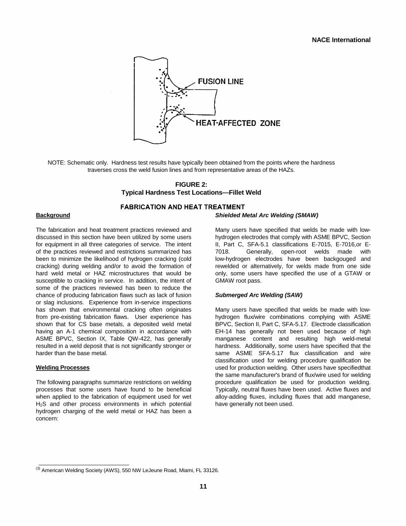
Butt Weld Test For butt welds, some users have specified that the hardness survey include readings transverse to the centerline of the weld from base metal through the weld and into the adjoining base metal as shown in Figure 1. To avoid interference with one another (which would affect accuracy), some users have specified that the hardness readings not be taken closer to one another than the width of one impression. Some users have required multiple traverses across the weld, such that the full thickness of the weld is represented in the test. Fillet Weld Test Some user experience has shown that hardness survey results from a butt weld WPQT are not representative of production fillet and corner welds. In examinations of cracked equipment, these types of welds have been found to have the hardest HAZ microstructures, which have resulted in severe cracking problems. When this type of weld joint is to be used, some users have specified additional WPQTs that are more representative of the production joint configurations and welding positions. Figure 2 shows the type of hardness survey that has been specified by some users for a fillet weld. This type of weld joint is a common joint design for tray rings and other internal attachments. Hardness Acceptance Criteria Some users have specified a maximum hardness of 200 HBW for the weldment, including the HAZ. This value was taken from NACE Standard RP0472, which recommends a maximum hardness of 200 HBW for weld metal. By direct10
conversion, this is equivalent to 210 HV10; however, experience has shown that the large indenter used in the Brinell test tends to produce a hardness test result that reflects the average of harder and softer zones within the larger area of the indention, whereas the smaller indenters used in the Vickers diamond-pyramid hardness test or the Rockwell superficial hardness test tend to produce a hardness test result that better reflects the hardness within a local hard or soft zone in the HAZ. Some users have specified a maximum hardness of 248 HV10 when utilizing these small indenter tests. The Rockwell superficial hardness equivalent to 248 HV10 is 70.5 HR15N. These values are a direct conversion from the 22 HRC maximum specified in NACE Standard MR0103 for ferritic materials to be used in petroleum refining “sour service.” The 248 HV10 maximum value is also supported by some laboratory testing and field experience in oil and gas production environments.18,19,20 Most users have found that a maximum of 200 HV10 for a CS weld HAZ is overly restrictive and not practical, especially for attachments welded with low-heat-input welding processes and 248 HV10 is often used. The Rockwell superficial hardness equivalent to 200 HV10 is 90.8 HR15T. Also, most users have found that a maximum of 210 HV10 has been satisfactory and practical for weld metal on a WPQT, particularly when the production weld metal has been tested to 200 HBW maximum hardness using a comparison hardness tester.
NOTE: Schematic only. Hardness test results have typically been obtained from the points where the hardness traverses cross the weld fusion lines and from representative areas of the HAZs.
FIGURE 1:
Typical Hardness Test Locations—Butt Weld
NACE International
NOTE: Schematic only. Hardness test results have typically been obtained from the points where the hardness
traverses cross the weld fusion lines and from representative areas of the HAZs.
FIGURE 2: Typical Hardness Test Locations—Fillet Weld
ENT
FABRICATION AND HEAT TREATM
Background The fabrication and heat treatment practices reviewed and discussed in this section have been utilized by some users for equipment in all three categories of service. The intent of the practices reviewed and restrictions summarized has been to minimize the likelihood of hydrogen cracking (cold cracking) during welding and/or to avoid the formation of hard weld metal or HAZ microstructures that would be susceptible to cracking in service. In addition, the intent of some of the practices reviewed has been to reduce the chance of producing fabrication flaws such as lack of fusion or slag inclusions. Experience from in-service inspections has shown that environmental cracking often originates from pre-existing fabrication flaws. User experience has shown that for CS base metals, a deposited weld metal having an A-1 chemical composition in accordance with ASME BPVC, Section IX, Table QW-422, has generally resulted in a weld deposit that is not significantly stronger or harder than the base metal. Welding Processes The following paragraphs summarize restrictions on welding processes that some users have found to be beneficial when applied to the fabrication of equipment used for wet H2S and other process environments in which potential hydrogen charging of the weld metal or HAZ has been a concern:
11
Shielded Metal Arc Welding (SMAW) Many users have specified that welds be made with low- hydrogen electrodes that comply with ASME BPVC, Section II, Part C, SFA-5.1 classifications E-7015, E-7016,or E-7018. Generally, open-root welds made with low-hydrogen electrodes have been backgouged and rewelded or alternatively, for welds made from one side only, some users have specified the use of a GTAW or GMAW root pass. Submerged Arc Welding (SAW) Many users have specified that welds be made with low-hydrogen flux/wire combinations complying with ASME BPVC, Section II, Part C, SFA-5.17. Electrode classification EH-14 has generally not been used because of high manganese content and resulting high weld-metal hardness. Additionally, some users have specified that the same ASME SFA-5.17 flux classification and wire classification used for welding procedure qualification be used for production welding. Other users have specifiedthat the same manufacturer's brand of flux/wire used for welding procedure qualification be used for production welding. Typically, neutral fluxes have been used. Active fluxes and alloy-adding fluxes, including fluxes that add manganese, have generally not been used.
___________________________
(3) American Welding Society (AWS), 550 NW LeJeune Road, Miami, FL 33126.
dmalakoff
Text Box
FABRICATION AND HEAT TREATMENT
dmalakoff
Text Box
NACE International NACE International
Gas Metal Arc Welding (GMAW) Many users have specified that welds be made with filler metal complying with ASME BPVC, Section II, Part C, SFA-5.18. AWS(3) classification ER-70S-G has generally not been used because the filler metal chemistry is not controlled. Generally, the use of the GMAW pulsed-arc or spray transfer mode has been specified. Most users have avoided or restricted the use of the GMAW short-circuiting transfer or globular transfer modes. Some users have specified additional WPQTs when the GMAW process has been used for nozzle attachment welds or internal attachment welds. Generally, open-root welds made with the GMAW spray transfer mode have been backgouged and rewelded. Flux-Cored Arc Welding (FCAW) Many users have specified that welds be made with filler metal complying with ASME Section II, Part C, SFA-5.20. Self-shielding flux-cored welding processes have generally not been used for pressure boundary welds. AWS classifications EXXT-G and EXXT-GS have generally not been used because the filler metal chemistry is not controlled. FCAW has typically been performed using the globular or spray-transfer mode. Generally, all FCAW open-root welds have been backgouged and rewelded. Some users have specified additional WPQTs when the FCAW process has been used for nozzle attachment welds or internal attachment welds. Some other users have either prohibited the use of FCAW altogether or severely limited its application to flat or rolled welds. Gas Tungsten Arc Welding (GTAW) Many users have specified that welds be made with filler metal complying with ASME BPVC, Section II, Part C, SFA-5.18. AWS classification ER-70S-G has generally not been used because the filler metal chemistry is not controlled. Shielding Gases Shielding gases specified for the GMAW, FCAW, and GTAW welding processes have typically been welding grade, hydrogen-free, with a dew point of -40°C (-40°F) or lower. Preheat and Heat Input The following paragraphs summarize preheat and heat input practices that some users have found to be beneficial. Users have specified these practices as a way of controlling the cooling rate during welding, which in turn affects the weld metal and HAZ microstructures:
12
12
Preheat and Interpass Temperature As a minimum, most users specify a preheat temperature for thermal cutting, tack welding, and welding in accordance with the nonmandatory ASME BPVC, Section VIII, Division 1, Appendix R, or Division 2, Appendix D, as applicable. Additionally, some users have specified a higher minimum preheat temperature when the base metal CE has been greater than 0.40, or when the Cb (Nb) plus V has exceeded 0.01 wt%, or when the total amount of unspecified elements has exceeded 0.5 wt% (see paragraph on chemical analysis), unless a WPQT hardness survey has shown this to be unnecessary. When a higher preheat was deemed necessary because of base metal chemistry, a minimum preheat of 120°C (250°F) to 150°C (300°F) has typically been used. Many users have specified that the base metal and interpass temperature be maintained at no less than the preheat temperature until the weld is completed. When the welding process has been terminated prior to completion, some users have specified that partially completed welds be examined with magnetic particle testing and most users specify that the preheat temperature be reestablished prior to restarting welding. Internal Attachment Welds Most users have specified that the base metal be preheated to a temperature appropriate for the base metal thickness and/or chemistry when making temporary or permanent internal attachment welds to the pressure boundary. Additionally, some users have specified that the base metal be preheated from the opposite side of the member to which the attachment weld is to be made and that the preheat temperature be measured on the side of the member to which the attachment weld is to be made. This method of applying preheat has ensured that the required temperature has been achieved through the full material thickness. Heat Input Some users have specified that the welding heat input used for production welding (see ASME BPVC, Section IX, QW-409.1) be controlled to be not significantly less than the heat input used for any hardness-tested WPQT. PWHT Most users have specified that new equipment destined for wet H2S refinery service receive a PWHT whether or not PWHT is required by the regulatory design code. Some users have been more selective and have not specified PWHT if previous service experience with comparable equipment and materials in the same process environment

has been satisfactory without PWHT. Even if the latter option has been chosen, a stress-relief heat treatment of cold-formed heads has sometimes been performed. Most users have considered PWHT to be beneficial and necessary because if done properly it should result in relief of both residual welding and cold-forming stresses and provide some tempering of hard HAZ microstructures. Both of these effects have been considered by many users to help reduce susceptibility of equipment to SSC and/or SOHIC in wet H2S environments. The following paragraphs summarize PWHT practices that some users have found to be beneficial. PWHT Temperature The PWHT temperature specified for carbon steels has typically ranged from 607 ±14°C (1,125 ±25°F) to 635 ±14°C (1,175 ±25°F) for 1 h per 25 mm (1.0 in.) of thickness, or for 1 hr minimum if thinner material was used. It has been found that C-Mn steels with >0.12 wt carbon and microalloyed in the range of 0.015 wt <Cb + V < 0.03 wt% produce as-welded HAZ hardness of 341 HV10 when welded with low-heat input welding processes (i.e., <3 kJ/mm [76 kJ/in.]) and with low preheat defined in ASME BPVC, Section VIII, Division 1, Appendix R for P-No. 1 steels.21 Therefore, some users have specified PWHT at 635 ±14°C (1,175 ±25°F) for a minimum of 0.08 h/mm (2.0 h/in.) of thickness for microalloyed steels with Cb + V in this range. In addition, some users limit the time for PWHT when microalloyed steels contain Cb + V in this range because of precipitation hardening in the base metal and weld HAZ. When PWHT is specified because of microalloy content in the range of 0.015 wt% < Cb + V <0.03 wt%, a temperature of 635 ±14°C (1,175 ±25°F) for 2 h per 25 mm (1.0 in.) of thickness is used by some users. The lower PWHT temperature satisfies the ASME BPVC, Section VIII minimum requirement for stress relieving. However, this requirement was not formulated to address the wet H2S cracking susceptibility issue. On occasion, some users and steelmakers have found it necessary to use the lower PWHT temperature in order to preserve base metal mechanical properties, particularly if the steel has a low CE. This has tended to be of greater concern with the ASME SA-516 grade 70 material. Some users and fabricators have reported that use of 635°C (1,175°F) or higher PWHT temperature was necessary to achieve HAZ hardness below 248 HV10 when the steel contains intentional additions of microalloying elements, when the total amount of Cb (Nb) plus V exceeded 0.015 wt%, or when the total amount of
1213
NACE International
unspecified elements has exceeded 0.5 wt% (see paragraph on chemical analysis). However, use of high PWHT temperatures can result in a reduction of base metal strength and notch toughness.13,22 Some users concerned about the effects on tensile strength produced by subsequent PWHT cycles necessitated by field repairs and/or use of higher PWHT temperatures have specified lower-strength base materials, such as ASME SA-516 grade 60, for new equipment. When such lower-strength options have been chosen, design parameters may have been adjusted to accommodate the lower strength levels. Although reductions in tensile strength resulting from subsequent PWHT cycles and/or higher PWHT temperatures have not generally been as high a concern with the lower-strength materials as with the higher-strength materials (e.g., grade 70), accompanying decreases in notch toughness in any of the grades may have occurred. Almost no users have adopted the use of a PWHT temperature lower than 607 ±14°C (1,125 ±25°F) for a longer time, as permitted by the ASME BPVC. Heat-Up and Cool-Down Rates and Temperature Differentials Maximum heat-up and cool-down rates and temperature differentials have typically been controlled in accordance with ASME BPVC, Section VIII, Division 1, UCS-56 or Division 2, AF-402, as applicable. Additionally, some users have specified that, during heat-up and cool-down, the maximum differential temperature not exceed 140°C (250°F) between the thickest and thinnest pressure boundary components, as measured at the weld, so as to minimize residual stresses and distortion. PWHT Procedure In order to better control the PWHT process, many users have specified that equipment fabricators prepare a PWHT procedure to be reviewed and agreed on prior to PWHT. Typically, this procedure has detailed the type of heating process or furnace to be used, number and location of thermocouples, locations of equipment supports during PWHT, heat-up and cool-down rates (including maximum temperature differentials permitted), soaking time, and PWHT temperature range. Welding After PWHT Almost all users have specified that no welding, hammering, or cutting be performed after PWHT. In addition, some users have specified that grinding be performed with consideration for limiting local heating to less than 260°C (500°F).

NACE International
General Welding Practices The following paragraphs summarize weld design, profile, and finish practices that some users have found to be beneficial. The intent of most of these practices has been to aid the performance of nondestructive examination (NDE): Weld Reinforcement Some users have specified that the inside weld surface reinforcement and edges be reasonably smooth to avoid the introduction of stress raisers and to facilitate wet magnetic particle testing (WMT). Users have reported that discontinuity-generating profiles such as welds overly reinforced with high crowns, or with the tops of crowns ground flat to create sharp side edges, and welds with rough bead profiles cannot be readily inspected with WMT.1
Removal of Attachments and Arc Strikes Some users have specified that the remains of any internal temporary attachments, line-up clamps, backing bars, and arc strikes be ground to bright metal and inspected with WMT. When weld deposits have been used to re-establish material thickness, the surface has typically been ground flush and the weld hardness-tested in addition to WMT. Some users have specified that special repair welding procedures with WPQT for weld and HAZ hardness control be used. Design of Attachment Welds Most users have specified that attachments be joined by continuous fillet welds and prepared for WMT. However, some users have specified that internal attachment welds be full-penetration, designed to permit access for WMT and subsequent in-service evaluation by ultrasonic inspection.
NONDESTRUCTIVE EXAMINATION (NDE)
The NDE practices reviewed in this section have commonly been applied to new equipment intended for use in all three categories of service. Many users have specified these practices to supplement the minimum requirements of ASME BPVC, Section VIII. Personnel Qualifications Most users have specified that NDEs be performed by personnel certified in accordance with ASNT Recommended Practice SNT-TC-1A, or equivalent. Additionally, some users have specified that personnel interpreting examination results be certified to Level II or III. WMT Most users have specified WMT as a surface examination technique for new equipment welds. Two types of WMT are employed in the industry. These are wet fluorescent magnetic particle testing (WFMT) and contrast wet magnetic particle testing (CWMT). WFMT has been the most frequently used and is considered by most users to be the more sensitive technique. WMT inspection has been found to be very sensitive, and has sometimes detected discontinuities and weld flaws not detected by visual examination or by other NDE techniques. User experience has shown that some of the discontinuities detected by WMT are nonrelevant because they have been created by changes in section, induced residual magnetic fields, inherent material properties, grinding or machining marks, weld ripples, etc. Some of these discontinuities have been found not to be detrimental; however, all such discontinuities have usually been re-examined and/or investigated to determine whether they were relevant. ASME SE-709, Paragraph 20.1 states that: “The overall
4
performance/sensitivity of a magnetic particle examination system is dependent upon the following: operator capability if a manual operator is involved, control of process steps, the particles or suspension, the equipment, visible light level, black light monitoring where applicable, magnetic field strength, field direction of orientation, residual field strength. These factors should all be controlled individually. The frequency of checks should be stated in the magnetic particle examination procedures of the testing facility. Records of the checks and results should be maintained.” Further details on methods for checking system performance and sensitivity are provided in ASME SE-709, Paragraphs 20.2 through 20.8. The following paragraphs summarize practices for WMT that most users have found to be beneficial. Extent of Examination Most users have specified that all accessible internal welds on pressure boundaries be inspected with WFMT. Examination has usually included a band of base metal 25-mm (1.0-in.) to 75-mm (3.0-in.) wide on each side of the toe of the weld. Some conditioning (brushing, blast cleaning, or grinding) of the surface has typically been used to provide a suitable surface for WFMT. Some users have specified that testing be performed a minimum of 48 hours after completion of welding. This waiting period has been found to increase the likelihood of detecting delayed hydrogen cracks from welding. Many users have specified that WMT be performed after PWHT on heat-treated equipment. Some users have specified that WMT be performed after hydrotest. When weld repairs have been made after PWHT and/or hydrotest,

NACE International
another PWHT and hydrotest have typically been performed. Examination Procedure Many users have specified an examination procedure in accordance with ASME BPVC, Section V, Article 7 with acceptance criteria in accordance with ASME BPVC, Section VIII, Division 1, Appendix 6 or Division 2, Appendix 9, Article 9-1, as applicable. Additionally, some users have specified that no relevant or nonrelevant linear indications be permitted. This more stringent acceptance criterion has been used to ensure that any small indications found during subsequent in-service inspection are not preexisting fabrication indications. Most users and inspection agencies have used the AC magnetic yoke method to reduce the likelihood of arc burns resulting in hard spots; however, some users have permitted DC methods prior to PWHT on equipment that will receive a PWHT.15
Radiography and Ultrasonic Examinations In addition to regulatory design code requirements, some users have specified that main longitudinal and circumferential welds be 100% examined by radiography. For selected equipment items, some users have specified that conventional nozzle-to-shell corner joints be inspected with shear-wave ultrasonic testing. On heavier-wall equipment, greater than 50 mm (2.0 in.) thick, some users have specified shear-wave ultrasonic examination of longitudinal and circumferential welds, in addition to the code-required radiographic examination. For some high-pressure equipment or cyclic service items, shell connections with sweep-type nozzles have been specified by some users because these joints are readily inspected with radiography or shear-wave ultrasonic testing. Fabricators have reported that many users fail to specifically define the extent of radiography or ultrasonic inspection to be performed. This has resulted in many misunderstandings during equipment fabrication and inspection.
PRODUCTION HARDNESS TESTINGBackground The production hardness testing practices reviewed in this section have been specified by most users as a final check of the weld metal macrohardness. This testing has been shown to identify gross misuse of welding consumables and/or fabrication techniques. Appropriately selected welding consumables and fabrication methods as described in NACE Standard RP0472 have been shown to typically produce weld deposits with hardness values below 200 HBW. There does not presently exist a practical hardness testing method for use on the actual HAZs of production weldments. Limiting weld deposit hardness to 200 HBW, in conjunction with the materials selection considerations, welding, fabrication, and heat treatment practices reviewed in this report, typically has been found to control the associated HAZ hardness to a level low enough to prevent SSC in most wet H2S refinery environments.
Production Testing Most users have specified that the hardness readings be taken on the side of the weldment to be exposed to the process environment of concern. In equipment, main pressure-retaining welds have typically been tested at least once every 3 m (10 ft) of linear weld, with a minimum of one reading per weld seam. Butt welds in nozzles and connecting chambers have typically been tested at a frequency of one test per weld. Weldments made with the SMAW process using electrodes in accordance with ASME BPVC, Section II, Part C, SFA-5.1, E-70XX have usually been exempt from hardness testing. Testing has usually been performed after completion of the final PWHT on heat-treated equipment. Acceptance Criterion Most users have specified 200 HBW maximum deposited weld hardness.
NACE International
NACE International
REFERENCES
1. R.D. Merrick, “Refinery Experiences with Cracking in Wet H2S Environments,” CORROSION/87, paper no. 190 (Houston, TX: NACE International, 1987). 2. R.D. Merrick, M.L. Bullen, “Prevention of Cracking in Wet H2S Environments,” CORROSION/89, paper no. 269 (Houston, TX: NACE , 1989). 3. J.H. Kmetz, D.J. Truax, “Carbonate Stress Corrosion Cracking of Carbon Steel in Refinery FCC Main Fractionator Overhead Systems,” CORROSION/90, paper no. 206 (Houston, TX: NACE, 1990). 4. R.R. Petrie, E.M. Moore, Jr., “Determining the Suitability of Existing Pipelines and Producing Facilities for Wet Sour Service,” Materials Performance 28, 6 (1989): p. 59. 5. A. Newman, “Sour Water Design by Charts,” Parts 1, 2 & 3, Hydrocarbon Processing 70, 9 (1991): p. 145; 70, 11 (1991): p. 101; 70, 11 (1991): p. 139. 6. K.E. Orie, F.B. Fletcher, “Performance Characteristics of Special Clean Pressure Vessel Steel Subjected to SSC and HIC Testing,” CORROSION/99, paper no. 632 (Houston, TX: NACE, 1999). 7. “Effect of Micro-Alloying Elements (Nb, V, Ti) on Properties of TMCP Steel Weldments,” Survey Report, Sumitomo Metal Industries, Ltd.,( 4) November 1985. 8. M.S. Cayard, R.D. Kane, R.J. Horvath, “SOHIC Resistance of C-Mn Plate Steels Used in Refinery Service,”CORROSION/2002, paper no. 554 (Houston, TX: NACE, 2002). 9. P. Xu, B.R. Somers, A.W. Pense, “Vanadium and Columbium Additions in Pressure Vessel Steels,” WRC(5) Bulletin 395, September 1994. 10. “HAZ Toughness of Structural and Pressure Vessel Steels, Improvement and Prediction,” AWS Welding Research Supplement, Welding Journal 58, 8 (1979). 11. “Effect of Columbium and Vanadium on the Weldability of HSLA Steels,” AWS Welding Research Supplement, Welding Journal 58, 6 (1979). 12. “A516 Steels Including HIC-Tested A 516 Steels,” Lukens Steel Company, Coatesville, PA, Technical Services Bulletin No. 778: November 1992.15 16
13. K.E. Orie, E. Upitis, “The Effect of Post Weld Heat Treatment and Notch Toughness on Weld Joints and on Normalized Base-Metal Properties of A-516 Steel,” WRC Bulletin 481, May 2003. 14. A.C. Gysbers, “Chemistry Considerations of P1 Base Materials to Mitigate Hydrogen Embrittlement Exposure,” CORROSION/2006, paper no. 575 (Houston, TX: NACE, 2006). 15. A.D. Wilson, E.G. Hamburg, “HIC Testing of A 516 Grade 70 Steels,” CORROSION/93, paper no. 542 (Houston, TX: NACE, 1993). 16. E.G. Hamburg, A.D. Wilson, “Hydrogen-Induced Cracking (HIC) Resistance of A 516 Grade 70 Plate Steel,” AIME-TMS Conference, Metallurgy of Vacuum-Degassed Steel Products, held October 3-5, 1989, Indianapolis, IN. 17. R. Blondeau, J. Charles, L. Coudreuse, “Clean Steel to Resist Hydrogen Embrittlement,” CORROSION/90, paper no. 202 (Houston, TX: NACE, 1990). 18. T.G. Gooch, “Hardness and Stress Corrosion Cracking,” The Welding Institute Research Bulletin, August 1982, p. 241. 19. R.J. Pargeter, “Factors Affecting the Susceptibility of C-Mn Steel Welds to Cracking in Sour Environments,” ASTM International Symposium on Environmental Assisted Cracking: Science and Engineering, held November 9-11, 1987, Bal Harbor, FL.(6) 20. N. Bailey, T.G. Gooch, R.J. Pargeter, “The Effect of Environment on Threshold Hardness for Hydrogen Induced Stress Corrosion Cracking of C-Mn Steel Welds,” 5th International Symposium of the Japanese Welding Society on Advanced Technology in Welding, Materials Processing and Evaluation, held April 17-19, 1990, Makuhari, Tokyo. 21. T. Phillips, D. Kloss, “What Has Happened to SA-516-70?,” in Proc. 12th International Corrosion Congress, held September 19-24, 1993 (Houston, TX: NACE, 1993), p. 778. 22. J. Glen, T.F. Gulvin, D.M. Haddrill, D. Scott, “The Influence of Stress Relief on the Properties of C and C-Mn Pressure-Vessel Plate Steels,” Proceedings of the Conference on the Effect of Modern Fabrication Techniques on the Properties of Steels (paper no. 621), held May 12, 1972 (Glasgow, Scotland: The West of Scotland Iron and Steel Institute, 1972).
___________________________ (4) Sumitomo Metal Industries Ltd., 5-33 Kitahama 4-chome, Chuo-ku, Osaka 541-0041, Japan.(5) Welding Research Council (WRC), PO Box 201547, Shaker Heights, OH 44120.
NACE International
NACE International
APPENDIX A REFERENCED CODES, SPECIFICATIONS, STANDARDS AND PUBLICATIONS
The following codes, specifications, standards and publications are referenced or discussed in this report or the appendixes. American Petroleum Institute (API)(7) Publication 581 Base Resource Document on Risk-
Based Inspection RP 580 Risk-Based Inspection RP 582 Welding Guidelines for the
Chemical, Oil, and Gas Industries RP 945 Avoiding Environmental Cracking in
Amine Units American Society for Nondestructive Testing (ASNT)(8) SNT-TC-1A Recommended Practice for
Personnel Qualification and Certification in Nondestructive Testing
ASME International (ASME)(9) Boiler and Pressure
Vessel Code (BPVC) Section II, Part A Materials, Ferrous Material
Specification (see detail specifications below)
Section II, Part C Materials, Specification for
Welding Rods, Electrodes, and Filler Metals
Section V Nondestructive Examination Section VIII, Division 1 Rules for Construction of
Pressure Vessels Section VIII, Division 2 Rules for Construction of
Pressure Vessels ― Alternative Rules
Section IX Welding and Brazing
Qualifications
117
ASME BPVC, Section II, Part A ― Ferrous Material Specification(10) SA-105/SA-105M Specification for Carbon Steel
Forgings for Piping Components
SA-106/SA-106 Specification for Seamless
Carbon Steel Pipe for High-Temperature Service
SA-179/SA-179M Specification for Seamless
Cold-Drawn Low-Carbon Steel Heat-Exchanger and Condenser Tubes
SA-193/SA-193M Specification for Alloy Steel and
Stainless Steel Bolting Materials for High Temperature or High-Pressure Service and Other Special Purpose Applications
SA-210/SA-210M Specification for Seamless
Medium-Carbon Steel Boiler and Superheater Tubes
SA-214/SA-214M Specification for Electric-
Resistance-Welded Carbon Steel Heat-Exchanger and
SA-216/SA-216M Specification for Steel Castings,
Carbon, Suitable for Fusion Welding for High Temperature Service
SA-234/SA-234M Specification for Piping Fittings
of Wrought Carbon Steel and Alloy Steel for Moderate and High Temperature Service
SA-263 Specification for Stainless
Chromium Steel-Clad Plate SA-264 Specification for Stainless
Chromium-Nickel Steel-Clad Plate
___________________________
(6) Preprints available from TWI (formerly The Welding Institute), Granta Park, Great Abington, Cambridge CB1 6AL, United Kingdom. (7) American Petroleum Institute (API), 1220 L Street NW, Washington, DC 20005-4070. (8) American Society for Nondestructive Testing (ASNT), PO Box 28518, 1711 Arlingate Lane, Columbus, OH 43228-0518. (9) ASME International (ASME), Three Park Ave., New York, NY 10016-5990. (10) Equivalent ASTM specifications have often been substituted when permitted by the ASME BPVC.
6
NACE International
NACE International
SA-265 Specification for Nickel andNickel-Base Alloy-Clad Steel Plate
SA-266/SA-266M Specification for Carbon Steel
Forgings for Pressure Vessel Components
SA-320/SA-320M Specification for Alloy Steel and
Stainless Steel Bolting Material for Low-Temperature Service
SA-333/SA-333M Specification for Seamless and
Welded Steel Pipe for Low-Temperature Service
SA-350/SA-350M Specification for Carbon and
Low-Alloy Steel Forgings, Requiring Notch Toughness Testing for Piping Components
SA-352/SA-352M Specification for Steel Castings,
Ferritic and Martensitic, for Pressure-Containing Parts, Suitable for Low Temperature Service
SA-420/SA-420M Specification for Piping Fittings
of Wrought Carbon Steel and Alloy Steel for Low-Temperature Service
SA-516/SA-516M Specification for Pressure
Vessel Plates, Carbon Steel, for Moderate- and Lower-Temperature Service
SA-578/SA-578M Specification for Straight-Beam
Ultrasonic Examination of Plain and Clad Steel Plates for Special Applications
SE-709 Standard Guide for Magnetic
Particle Examination. NACE International MR0103 Materials Resistant to Sulfide
Stress Cracking in Corrosive Petroleum Refining Environments
16
18
MR0175/ISO(11) 15156 Petroleum and natural gas industries—Materials for use in H2S-containing environments in oil and gas production
RP0170 Protection of Austenitic
Stainless Steels and Other Austenitic Alloys from Polythionic Acid Stress Corrosion Cracking During Shutdown of Refinery Equipment
RP0178 Fabrication Details, Surface
Finish Requirements, and Proper Design Considerations for Tanks and Vessels to Be Lined for Immersion Service
RP0188 Discontinuity (Holiday) Testing
of New Protective Coatings on Conductive Substrates
RP0292 Installation of Thin Metallic
Wallpaper Lining in Air Pollution Control and Other Process Equipment
RP0296 Guidelines for Detection,
Repair, and Mitigation of Cracking of Existing Petroleum Refinery Pressure Vessels in Wet H2S Environments
RP0472 Methods and Controls to
Prevent In-Service Environmental Cracking of Carbon Steel Weldments in Corrosive Petroleum Refining Environments
TM0103 Laboratory Test Procedures for
Evaluation of SOHIC of Plate Steels Used in Wet H2S Service
TM0284 Evaluation of Pipeline and
Pressure Vessel Steels for Resistance to Hydrogen-Induced Cracking
___________________________
(11) International Organization for Standardization (ISO), 1 rue de Varembe, Case Postale 56, CH-1121 Geneva 20, Switzerland.

NACE International
NACE International
APPENDIX B: WATER WASHING, POLYSULFIDE INJECTION, AND
CORROSION INHIBITOR INJECTION
Introduction Reducing corrosion of CS in wet H2S environments decreases the amount of atomic or nascent hydrogen adsorbed on the steel and thus reduces the severity of hydrogen damage. Although no quantitative relationships have been established between corrosion rate and cracking severity, experience has shown that substantial reduction of blistering, HIC, and SOHIC have been obtained by corrosion control measures such as water washing, polysulfide injection, and inhibitor injection. An exception is the case of hardened weldments, where such measures have not reduced or prevented SSC. Because most hydrogen blistering, HIC, and SOHIC problems have occurred in light ends or vapor recovery units that take feed from FCCUs and DCUs, the measures discussed in this appendix have frequently been applied to these units. Additionally, these measures have sometimes been applied in other units that have been subject to wet H2S environments. Water Washing Extensive field experience has shown that continuous water washing of sour gas/vapor streams is an effective method of reducing hydrogen damage to steel. Aqueous corrosion produces atomic hydrogen that often enters the steel and causes blistering or cracking. Applied correctly, water washing dilutes the concentration of corrodents in the process stream. It also prevents the deposition of acidic salts that cause corrosion. Water washing has been done by contacting the gas/vapor with water in a scrubbing tower, or by injecting the water directly into process piping. Water injection into piping is often used, provided there is sufficient separation and removal capability available at some point downstream to remove the water. The amount of injected water is dependent on the gas/vapor flow rate and operating conditions, the amount and types of corrosives present in the stream, and the concentration of corrosives in the resultant sour water. Monitoring of effectiveness is often performed in order to maintain an appropriate water wash system. Typically, wash water has been injected through a distributor nozzle or quill located at the center of the piping. Most users have specified a sufficient length of straight run piping downstream from the injection point to try to ensure proper mixing ahead of coolers and condensers, and to try to prevent impingement attack on piping bends, elbows, and tees. When the piping branches into multiple banks of16 19
heat exchangers, an injection point upstream from each exchanger has often been used. Both the inlet and outlet piping for these heat exchangers are often flow balanced and symmetrical to ensure even distribution of the process and wash water, allowing for a smaller number of injection points. Typical water sources have been sour water condensate, stripped sour water, boiler feedwater (BFW), and steam condensate. Wash water quality is defined by oxygen content, solids content, conductivity, or pH. NACE Publication 34101 provides guidance for design of wash water injection points. Polysulfide Injection Continuous injection of polysulfide solution has often been used when there was evidence of cyanides in water wash effluent, or when downstream equipment has experienced blistering, HIC, or SOHIC. Polysulfide injection has often been used when water washing alone had not decreased the free cyanide content below 20 ppmw in sour water. Polysulfide lowers the cyanide (CN-) content of sour water by transforming it to thiocyanate (SCN-). Additionally, polysulfide is a strong sulfiding agent that produces a more protective film on steel surfaces. The injection point parameters discussed in the section on water washing have also been typically applied to polysulfide injection. The amount of polysulfide injection is set based on a trend of data for HCN in the sour water. The injection rate has typically been adjusted so that the amount of polysulfide sulfur added is somewhat in excess of the stoichiometric amount required for conversion of CN- to SCN-. While several types of polysulfide solutions are available, a commercial 55 wt% ammonium polysulfide solution has typically been used. Sodium polysulfide solution has not commonly been used because it increases sour water condensate pH, reacts more slowly with HCN in comparison with ammonium polysulfide, and is more expensive than ammonium polysulfide solution. To mitigate sulfur deposition, polysulfide solution has typically been diluted by a factor of 10 with a slip stream of wash water prior to injection into the wash water streams. It has also been considered important to keep oxygen out of the storage tank with the use of a layer of hydrocarbon liquid or inert gas blanket. Sulfur deposition can also be caused by elevated temperature or low pH conditions. Alkaline sour water containing both H2S and NH3 has typically been used for dilution.
NACE International
Corrosion Inhibitor Injection Polar organic compounds containing nitrogen, sulfur, and oxygen are often used as corrosion inhibitors to help minimize hydrogen adsorption onto the steel surface. The most effective inhibitors against hydrogen entry have been film-forming amines. Typically, these inhibitors consist of a long-chain (C >10) hydrophobic group and a suitable hydrophilic group. Adsorbed inhibitor retards hydrogen entry in one or more of the following ways: • By forming a physical barrier film that reduces contactbetween the corrosive medium and the steel surface; • By partially blocking active sites on the steel surface for
hydrogen adsorption; and
16
20
• By increasing the kinetics of the hydrogen evolution reaction and, thus, decreasing the concentration of adsorbed hydrogen atoms.
Commercial film-forming amines have been known to help prevent hydrogen blistering of steel, provided the inhibitor concentration was sufficient on the surface. The successful use of filmers is dependent on proper injection and distribution in a system to reach the potential areas of corrosion. Measures such as water washing and polysulfide injection are often used in conjunction with corrosion inhibitor injection as part of a comprehensive corrosion control program.
APPENDIX C: LINERS FOR THE PREVENTION OF
HYDROGEN CRACKING AND BLISTERING
Introduction Various types of liners have been used to prevent hydrogen cracking and hydrogen blistering of equipment in wet H2S service. Liner is a generic term for several different constructions; however, their purposes are the same. A liner separates the CS wall from the process environment to prevent corrosion. Atomic hydrogen is generated by the corrosion reaction; therefore, if corrosion is stopped, hydrogen cracking (SSC, HIC, SOHIC) or blistering cannot occur. Types of liners discussed in this appendix include alloy weld overlay, alloy integral lining, alloy strip lining, organic thin-film coatings, and other miscellaneous linings and coatings such as cement lining and thermal spray coatings. Liners have been used for both existing and new equipment. Each type of liner has been found to have benefits and pitfalls. Users have typically reviewed the reason for lining, such as whether it is a temporary repair or a long-term solution, when they have selected the type of liner to use. Alloy Weld Overlay Alloy weld overlay has been found to be a permanent solution to hydrogen cracking and blistering, provided the overlay material was resistant to corrosion in the service and was properly applied. Appendix B of API RP 582 provides guidance for weld overlay and back cladding. This method of lining has provided excellent reliability; however, it has been found to be costly and time-consuming, particularly if field applied. This type of lining allows continued inspection of the internal surface without concern for the material behind the weld overlay. Before proceeding with a weld overlay users have typically:• Selected material for the overlay that would resist
corrosion in the given environment and resist sensitization during fabrication. Austenitic SSs have been the most common type of corrosion-resistant material selected; however, in some services users have selected nickel-based alloys for greater corrosion resistance, particularly when chlorides have been present in the process.
• Specified the overlay to meet minimum thickness and deposit chemistry requirements after fabrication. Dilution effects have been considered.
• Reviewed the potential for distortion of the base metal as a result of weld shrinkage stresses.
Most users have specified chemically stabilized or low-carbon austenitic SSs for the weld deposit, particularly for equipment that will receive a PWHT. PWHT of equipment has resulted in sensitization of austenitic SSs that were not chemically stabilized or low-carbon. Sensitization occurs as chromium carbides precipitate at grain boundaries, reducing the chromium content adjacent to the grain boundaries, resulting in a reduction of corrosion resistance. Additional information about these characteristics is found in NACE Standard RP0170. Most users have been very careful in the selection of the welding process and the filler metals to achieve weld deposit chemistry for proper corrosion resistance and resistance to sensitization, as well as having a percent ferrite range of 4 to 10 to reduce hot cracking and disbonding. The filler metal specifications for bare strip electrodes and bare wires provide a chemistry control of the electrode but not the weld deposit. High-heat-input welding processes such as submerged arc welding (SAW) using strip

NACE International
electrodes have caused dilution of the chemistry from both the base metal and interaction with the flux. In order to maintain reasonable Cr and Cb (Nb) limits, fluxes with some added Cr and Cb (Nb) have sometimes been utilized on the final layer such that the deposit would not become depleted of these alloying elements. Inspection of weld overlays has typically included liquid penetrant examination, ultrasonic testing, ferrite testing, and weld chemistry verification. Alloy Integral Clad Lining (Clad Plate) Clad plate material meeting the requirements of ASME SA-263, SA-264, or SA-265 has most frequently been used in the construction of new equipment; however, it has also been retrofitted into existing equipment where possible (e.g., flanged boots). Clad plate has had similar reliability and has been subject to the same selection criteria as weld overlay but without the concern for the dilution effects encountered with weld overlay. Appendix B of API RP 582 provides guidance for clad restoration and back cladding. Most users regard clad plate as a permanent solution for hydrogen cracking and blistering problems, provided the proper alloy cladding material has been selected for the corrosive service. Clad plate has been cost effective, as discussed in Appendix D. Fabrication practices for clad plate have involved the usual process of making a sound joint in the pressure-retaining backing material, followed by weld overlay on the alloy side to tie in the joined clad plates. Clad plate fabrication utilizes alloy weld overlay at nozzles and flanges. Specific welding procedures have depended on the weld joint configuration, material type, welding processes, consumables, and clad plate thickness. User specifications for inspection of equipment fabricated from clad plate have typically included all the considerations for alloy weld overlay, as discussed in the previous section, for the weld seam areas and ultrasonic testing of the clad area to verify that fabrication operations have not resulted in disbonding. Alloy Strip Lining Alloy strip lining is a field technique that has been commonly applied to minimize corrosion in existing equipment. It has been effective in preventing cracking and blistering when the alloy lining material resisted the corrosive environment and had been properly installed. A common drawback to strip lining has been the fact that the liner prevents any inspection underneath, other than external ultrasonic or radiographic examination. This has been a concern because experience has shown that in time most liners have leaked at the welds, despite inspection of the attachment welds when they were made. In some cases, this leakage has resulted in SSC of hard attachment welds formed under the lining when the liner was attached with low-heat-input single-pass welds. Strip linings have21
generally not been the method of construction selected for new equipment; however, they have sometimes been used when there has been insufficient fabrication time available to permit the procurement of alloy clad plate. In some installations, strip linings have bulged and separated from the underlying base material when there have been vacuum conditions in the equipment or where there has been a buildup of hydrogen gas behind the liner. Much of the strip lining experience has been associated with power plant flue gas desulfurization systems, but the corrosion protection and installation techniques developed for this application have also been utilized in many applications for the petrochemical and refining industries. These techniques are discussed further in NACE Standard RP0292. Organic Thin-Film Coatings Users have reported mixed experiences with self-curing organic thin-film coatings applied to prevent wet H2S cracking. Some users have reported good experiences and successes with carefully selected and applied coatings. Other users have had limited success with their use for preventing wet H2S damage. Problems experienced have included holidays, which have promoted undercutting and delaminations. Coatings around corners and edges in equipment have tended to crack upon curing. Coatings have been found to be permeable and have tended to blister as a result of hydrogen and other light gas diffusion. In addition, self-curing organic thin-film coatings have limited temperature resistance. Because the integrity of a coating has been questionable, self-curing organic thin-film coatings have generally not been considered by many users as an effective long-term solution for use on new construction. Baked phenolics have demonstrated success as protective coatings for continuous wet H2S refinery service conditions below 120°C (250°F). Baked phenolics have generally been applied to small equipment but have been found to be subject to cracking or spalling in transportation because of the coating's brittle characteristics. Repairs to baked phenolics have been difficult and have not matched the quality of the baked product. The surface preparation for organic thin-film coatings has typically included grinding the weld surfaces and radiusing corners to suitable conditions for coating continuity. Surface preparation is discussed further in NACE Standard RP0178. When the phenolic coating system has included a primer coating, special care has usually been taken to ensure that it was dried properly and inspected prior to applying additional coats. The coating manufacturer's installation instructions were typically followed for preparation, application, drying, and inspection. Inspections of organic thin-film coatings have typically included holiday testing in accordance with NACE Standard RP0188.

NACE International
Other Linings and Coatings Some users have reported successes in preventing wet H2S cracking by use of other types of linings and coatings such as cement lining (gunite) and thermal spray processes to apply metallizing (aluminum, austenitic SS, nickel alloy)22
and TiO2. Most of these methods have been applied as maintenance linings or coatings and there has been little reported experience of these methods' being specifically selected for application to new equipment used in wet H2S refinery service.
APPENDIX D: COMPARATIVE EQUIPMENT COSTS FOR
DIFFERENT MATERIALS
Introduction The purpose of this appendix is to present comparative cost data for equipment constructed of standard CS, special clean steel plate tested for resistance to hydrogen-induced cracking (HIC-resistant), and CS clad with austenitic SS. PWHT was included for both the standard CS and the HIC-resistant CS equipment. In addition, a shop WFMT inspection was included for the CS equipment. These data were developed by members of WG T-8-16e and updated by TG 301 for inclusion in this report. Discussion The design information shown in Table D1 was used as the basis for the estimated cost ratios compared in Table D2. The design pressure was varied, as required, to allow the component thicknesses to remain the same. Other similarities were also chosen to keep the fabrication cost comparison as simple as possible. The components required for the equipment in Table D1 were each estimated with the material categories listed below. The major NDE planned for the material categories is also noted. Some of the NDE was assumed to be done at the material supplier's facilities, with the remaining examinations done at the fabricator's facilities.Standard CS SA-516 grade 70, as-rolled, 31.8-mm (1.25-in.) thick (including 3.18-mm [0.125-in.] corrosion allowance [CA]); SA-106 grade B pipe nozzles; SA-105 forged flanges; 100% radiography; WFMT; PWHT. HIC-Resistant CS SA-516 grade 70, normalized, 0.001 wt% maximum sulfur, HIC tested, UT per SA-578 Level A, 31.8-mm (1.25-in.) thick (including 3.18-mm [0.125-in.] CA); SA-333 grade 6 pipe nozzles; SA-350 grade LF2 forged flanges; 100% radiography; WFMT; PWHT. Carbon Steel with SS Cladding SA-516 grade 70, as-rolled backing material with UNS S30403 (type 304L SS) roll-bond clad in accordance with SA-264, 31.8-mm (1.25-in.) thick including a nominal 3.18-mm (0.125-in.) clad, UT per SA-578 Level A and S-7; SA-105 forged flanges with overlay; SA-106 grade B pipe nozzles with overlay as required; 100% radiography; 100% liquid penetrant examination of SS overlay welds.

NACE International
TABLE D1 DESIGN INFORMATION
METRIC UNITS
COMPONENT SIZE DESIGN
TEMPERATURE/PRESSURE
NOZZLES/ATTACHMENTS
Heat Exchanger (Shell Only)
1.2-m ID For 6.1-m
Long Bundle
343°C/ 4.65 to 5.17 MPa
DN(A) 250 Inlet, DN 250 Outlet
Vertical Column 23-m T/T 3.0-m ID
343°C/ 1.90 to 2.07 MPa
4 @ DN 600 Manways; 2 @ DN 250, 4 @ DN 100 Nozzles; 35 Tray Support Rings, No Trays
Horizontal Vessel 12-m T/T 3.0-m ID
343°C/ 1.90 to 2.07 MPa
2 @ DN 600 Manways; 2 @ DN 250, 4 @ DN 100 Nozzles
U.S. CUSTOMARY UNITS
COMPONENT SIZE DESIGN
TEMPERATURE/ PRESSURE
NOZZLES/ATTACHMENTS
Heat Exchanger (Shell Only)
48-in. ID For 20-ft
Long Bundle
650°F/ 675 to 750 psi
10 NPS(B) Inlet, 10 NPS Outlet
Vertical Column 75-ft T/T 10-ft ID
650°F/ 275 to 300 psi
4 @ 24 NPS Manways; 2 @ 10 NPS, 4 @ 4 NPS Nozzles; 35 Tray Support Rings, No Trays
Horizontal Vessel 40-ft T/T 10-ft ID
650°F/ 275 to 300 psi
2 @ 24 NPS Manways; 2 @ 10 NPS, 4 @ 4 NPS Nozzles
(A) DN is metric nominal pipe diameter (mm). (B) NPS is nominal pipe size (in.).
Although CS is the lowest initial cost material for new construction, some users have considered other life-cycle costs when making economic comparisons. These have included in-service inspections, any repair costs, and loss of production costs. Equipment lasting 20 years could be subjected to several additional in-service WMT inspections during its lifetime. Experience has shown these inspections to be very costly, particularly when defects were discovered, because defects have led to added costs for repair and more frequent subsequent inspections. Because austenitic SS clad equipment is not subject to SSC, HIC, SOHIC, or blistering, the extra maintenance expenses for inspection, welding, or repairs have usually been eliminated for clad equipment, as has the likelihood of unscheduled downtime. Therefore, some users have at times found it to be more cost-effective to accept the initial higher capital cost for a material that is more corrosion- resistant than to incur the costs of repeated inspections, repairs, and downtime. However, there have also been23 23
costs associated with the operation and maintenance of SS clad equipment, particularly the cost of neutralizing washes prior to opening the equipment during shut-downs and the cost of disposal of spent neutralizing solutions. These life-cycle costs have also been included in evaluations. Additionally, for some services a thinner cladding material has at times been adequate to provide full corrosion resistance and has resulted in greater cost effectiveness for larger clad equipment. However, there is a thickness of CS backing plate below which cladding has not been economically viable when compared with solid SS construction of the same design. This economic minimum backing material thickness has also been a function of the cost of the cladding material selected for corrosion resistance.
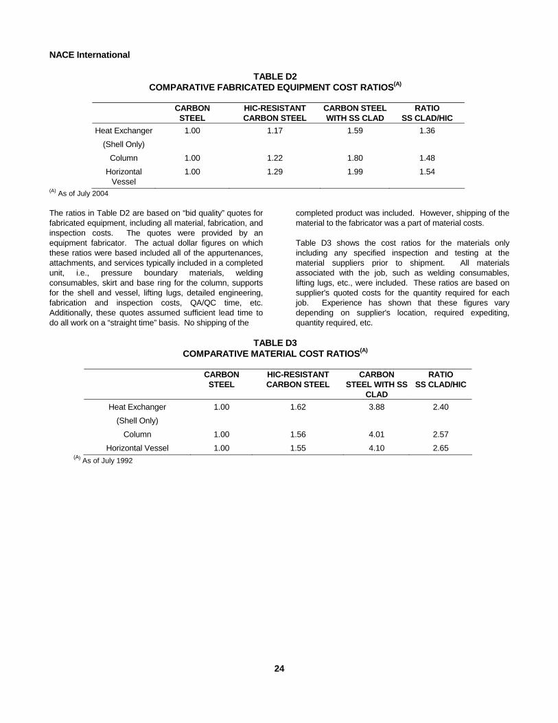
NACE International
TABLE D2 COMPARATIVE FABRICATED EQUIPMENT COST RATIOS(A)
CARBON
STEEL HIC-RESISTANT CARBON STEEL
CARBON STEEL WITH SS CLAD
RATIO SS CLAD/HIC
Heat Exchanger
(Shell Only)
1.00 1.17 1.59 1.36
Column 1.00 1.22 1.80 1.48
Horizontal Vessel
1.00 1.29 1.99 1.54
(A) As of July 2004
The ratios in Table D2 are based on “bid quality” quotes for fabricated equipment, including all material, fabrication, and inspection costs. The quotes were provided by an equipment fabricator. The actual dollar figures on which these ratios were based included all of the appurtenances, attachments, and services typically included in a completed unit, i.e., pressure boundary materials, welding consumables, skirt and base ring for the column, supports for the shell and vessel, lifting lugs, detailed engineering, fabrication and inspection costs, QA/QC time, etc. Additionally, these quotes assumed sufficient lead time to do all work on a “straight time” basis. No shipping of the24
completed product was included. However, shipping of the material to the fabricator was a part of material costs. Table D3 shows the cost ratios for the materials only including any specified inspection and testing at the material suppliers prior to shipment. All materials associated with the job, such as welding consumables, lifting lugs, etc., were included. These ratios are based on supplier's quoted costs for the quantity required for each job. Experience has shown that these figures vary depending on supplier's location, required expediting, quantity required, etc.
TABLE D3 COMPARATIVE MATERIAL COST RATIOS(A)
CARBON
STEEL HIC-RESISTANT CARBON STEEL
CARBON STEEL WITH SS
CLAD
RATIO SS CLAD/HIC
Heat Exchanger
(Shell Only)
1.00 1.62 3.88 2.40
Column 1.00 1.56 4.01 2.57
Horizontal Vessel 1.00 1.55 4.10 2.65 (A) As of July 1992