8PT2751 Circuit-Breaker Design Siemens SIVACON 8PT • 12/2003 4/1 Contents Page ACB - Circuit-breaker design with 3W. Incoming feeder, couplers and outgoing feeder cubicles 4/2 General 4/2 Structure and Functions 4/2 Auxiliary Compartment 4/2 Installation of Instruments 4/3 Cable/Bar Connection Compartment 4/3 Forms of Internal Separation/Doors 4/4 Short-Circuit and Earthing Facilities 4/4 Selecting Connection Bars for PE, N, PE/N and PEN 4/4 Rated Currents for 1 Circuit-Breaker/Cubicle with 3WN 4/5 Rated Currents for 2 Circuit-Breakers/Cubicle with 3WN 4/5 Rated Currents for 3 Circuit-Breakers/Cubicle with 3WN 4/6 Space Requirement for 3 and 4 pole 3WN Circuit-Breakers 4/7 Rated Currents for 1 Circuit-Breaker/Cubicle with 3WL 4/8 Rated Currents for 2 Circuit-Breaker/Cubicle with 3WL 4/8 Rated Currents for 3 Circuit-Breaker/Cubicle with 3WL 4/9 Space Requirement for 3 and 4 pole 3WL Circuit-Breakers 4/10 MCCB – Circuit-breaker design with 3WL Incoming Feeder and Outgoing Feeder Cubicles 4/10 Technical Description 4/11 Rated Currents 4/12 Space Requirement 4/12 Dimension drawing for bar connection 4/13 (Busbar connection from top)

Welcome message from author
This document is posted to help you gain knowledge. Please leave a comment to let me know what you think about it! Share it to your friends and learn new things together.
Transcript

8PT2751 Circuit-Breaker Design
Siemens SIVACON 8PT • 12/2003 4/1
Contents Page ACB - Circuit-breaker design with 3W. Incoming feeder, couplers and outgoing feeder cubicles 4/2 General 4/2 Structure and Functions 4/2 Auxiliary Compartment 4/2 Installation of Instruments 4/3 Cable/Bar Connection Compartment 4/3 Forms of Internal Separation/Doors 4/4 Short-Circuit and Earthing Facilities 4/4 Selecting Connection Bars for PE, N, PE/N and PEN 4/4 Rated Currents for 1 Circuit-Breaker/Cubicle with 3WN 4/5 Rated Currents for 2 Circuit-Breakers/Cubicle with 3WN 4/5 Rated Currents for 3 Circuit-Breakers/Cubicle with 3WN 4/6 Space Requirement for 3 and 4 pole 3WN Circuit-Breakers 4/7 Rated Currents for 1 Circuit-Breaker/Cubicle with 3WL 4/8 Rated Currents for 2 Circuit-Breaker/Cubicle with 3WL 4/8 Rated Currents for 3 Circuit-Breaker/Cubicle with 3WL 4/9 Space Requirement for 3 and 4 pole 3WL Circuit-Breakers 4/10 MCCB – Circuit-breaker design with 3WL Incoming Feeder and Outgoing Feeder Cubicles 4/10 Technical Description 4/11 Rated Currents 4/12 Space Requirement 4/12 Dimension drawing for bar connection 4/13 (Busbar connection from top)

Circuit-Breaker Design 8PT2751
4/2 Siemens SIVACON 8PT • 12/2003
General The circuit-breaker systems comprise cubicle types that are used exclusively for the incoming feeder into the switchboard and for outgoing feeders and couplings.
Structure and Functions The following cubicle types are available depending on function, switchgear rated currents and required short-circuit strength: Cable connection front (minimum cubicle depths)
600
400 - 800
800
400 - 1000
800
800 /1000
800
1000/1200
630 A - 3200 A 630 A - 6300 A 2000 A - 2500 A 630 A - 1600 A
FCB1 FCB2 FCB3 BC FCB2BC Cable connection rear
1000
400 - 80012
00
400 - 100012
00
600 / 80012
00
600
630 A - 3200 A 630 A - 6300 A 2000 A - 2500 A 630 A - 1600 A
FCB1 FCB2 FCB3 BC FCB2BC Cubicle type
Function Installation type
Size / Rated current
optional:
• Incoming feeder • coupling • outgoing feeder
optional:
• withdraw-able
• fixed-mounted
3WN size I - IV 630 – 6300 A 3WL size I - size III 630 – 6300 A
optional:
• incoming feeder and coupling
• 2 x incoming feeder/ outgoing feeder
optional:
• withdraw-able
• fixed-mounted
size II 2000 – 2500 A
• incoming feeder • outgoing feeder
optional:
• withdraw-able
• fixed-mounted
size I 630 - 1600 A
Auxiliary Compartment There are available type-specific auxiliary compart ments to integrate additional devices, e.g. for interlocking devices. Cubicle type with 1 circuit-breaker/cubicle: ← cross wiring compartment (optional) ← auxiliary compartment ← switching device compartment ← cable connection compartment
The auxiliary compartment is installed separately from the switching device compartment, independent of the form of internal separation. Switching device panel structure and dimensions:
13
3
a
b2 3
3 1
frame door
1 Terminal blocks 2 Mounting rail 3 Wiring duct
Cubicle width [mm] a b c 400 338 600 538 800 738 541 300 + 20
1000 938 Cubicle type with 2 circuit-breakers/cubicle: Cable connection front
← cross-wiring compartment (optional)
auxiliary compartment →
← cable connection compartment
1000 mm
a c
b

8PT2751 Circuit-Breaker Design
Siemens SIVACON 8PT • 12/2003 4/3
Dimensions [mm] 3WN a b c 3WL a b c 3-pol. 450 550 300 + 20 3-pol. 430 500 275 + 20 4-pol. 330 550 300 + 20 4-pol. 300 500 275 + 20
Cable connection rear ← cross-wiring compartment (optional) ← auxiliary compartment ← switching device compartment Switching device panel structure and dimensions:
13
3
a
b2 3
3 1
frame door
1 Terminal blocks 2 Mounting rail 3 Wiring duct
Cubicle width [mm] a b c
600 538 500 250 + 20 800 738 500 250 + 20
Cubicle type with 3 circuit-breakers/cubicle: Cable connection front A swing-out type compartment for auxiliary devices located in front of the cable termination busbars is added to every circuit-breaker compartment. ← cross wiring compartment (optional) ← cable connection compartment ← auxiliary → compartment
View from top: ← cable connection compartment ← auxiliary compartment Dimensions [mm]
a‘ b c 256 490 175
Cable connection rear There is available a L-type auxiliary compartment for the integration of terminal blocks.
Installation of Instruments The instruments are located in the door in front of the belonging auxiliary device unit. ATTENTION: With cubicle type 3 ACB/cubicle installation of
multiple or big size devices is restricted and may influence dimension "C" of the auxiliary devices. If necessary apply cubicle type 1 ACB/ cubicle.
With cubicle type 1 ACB/cubicle and function bus coupling the standard location of the auxiliary device unit is below the ACB compartment. Instruments with little depth can be located above the ACB as before.
Cable/Bar Connection Compartment Possibilities of connecting cables to 3W. circuit-breakers:
Cross-section Number of connectable cable cross-sections depending on rated current
3½-conductor [mm2] 630 A 800 A 1000 A 1250 A 1600 A
up to 240 4 4 4 61) 61)
3½-conductor [mm2] 2000 A 2500 A 3200 A 4000 A 5000 A
up to 300 9 9 11 14 182)
3½-conductor [mm2] 6300A2)
up to 300 18
1) 3 ACB/cubicle restrictedly with cable from below, there max. amount of cables per cubicle is 14 pieces 2) Incoming feeders/outgoing feeders of circuit-breakers > 4000 A are always effected with bar connection
According to the standards, only busbar connection from top can be project-planned.
a'
c
b

Circuit-Breaker Design 8PT2751
4/4 Siemens SIVACON 8PT • 12/2003
Forms of Internal Separation/Doors With SIVACON there exist various executions of the forms of in-ternal separation according to the requirements (detailed descrip-tion see chapter "General", page 11). The following door designs can be used depending on the form of internal separation: Form 1 Form 2b Form 3a Form 1 Form 1 Form 4b Form 3a Form 3a (not at BC) unventilated ≤ IP54 (A 150 mm deep plexiglass cover is necessary when using 3WL circuit-breaker). ventilated ≤ IP42
Short-Circuit and Earthing Facilities The following possibilities of short-circuiting and earthing are available depending on cubicle type:
• Short-circuiting and earthing accessories on the connection end (with type 1 ACB/cubicle): Short-circuit strength max. 100 kA Studs (see figure above) are required at the point to be earthed. The studs are secured in the front of the connection compartment on the connection bars.
• Withdrawable shorting and earthing unit on the connection or busbar end (with withdrawable type): The withdrawable shorting and earthing unit consists of the 3W.- circuit-breaker housing and features contact blades that are connected to the shorting jumper. Depending on the version, the shorting jumpers are located at the top and/or bottom. The earthing and short-circuit connections are already established on insertion of the withdrawable unit. It is imperative to verify dead state before cranking in the withdrawable unit!
Shorting and earthing accessories
Selecting Connection Bars for PE, N, PE/N and PEN Depending on the type of led-in cable used, it must be connected to the individual bars in the cabinet via connection bars:
Type of led-in cable Type of bar in the cabinet PE PE PEN PEN PE + N PE + N PEN PE/N*
*) One N conductor is branched off from the led-in PEN con-ductor to create the PE/N function. Busbars are connected to the relevant horizontal PE and N bars via bars. At the same time, the PE and N bars are connected in the cubicle via an isolating lug.
Earthing terminal
Earthing cable
Shorting bar Stud

8PT2751 Circuit-Breaker Design
Siemens SIVACON 8PT • 12/2003 4/5
Rated Currents for 1 Circuit-Breaker/Cubicle with 3WN Rated currents In as a function of ambient temperature 3WN Incoming feeder or outgoing feeder function Non-ventilated Ventilated
20° 25° 30° 35° 40° 45° 50° 20° 25° 30° 35° 40° 45° 50° Type [A] [A] [A] [A] [A] [A] [A] [A] [A] [A] [A] [A] [A] [A]
Rated current [A]
630 630 630 630 630 630 630 630 630 630 630 630 630 630 3WN60 630 800 800 800 800 800 800 800 800 800 800 800 800 800 800 3WN61 800
1000 1000 1000 1000 1000 1000 1000 1000 1000 1000 1000 1000 1000 1000 3WN62 1000 1250 1250 1250 1250 1250 1220 1180 1250 1250 1250 1250 1250 1250 1250 3WN63 1250 1600 1600 1580 1540 1500 1450 1410 1600 1600 1600 1600 1600 1600 1590 3WN64 1600 2000 2000 2000 2000 2000 1950 1890 2000 2000 2000 2000 2000 2000 2000 3WN65 2000 2500 2500 2450 2390 2330 2260 2190 2500 2500 2500 2500 2500 2500 2490 3WN66 2500 2750 2690 2620 2560 2490 2420 2340 3150 3070 3000 2920 2850 2770 2680 3WN67 3200 2570 2510 2450 2390 2320 2260 2190 3200 3200 3200 3140 3060 2970 2880 3WN17 3200 2930 2870 2800 2730 2650 2580 2500 3850 3760 3670 3570 3480 3380 3280 3WN18 4000 3770 3690 3600 3510 3410 3320 3220 4850 4740 4620 4510 4390 4260 4140 3WN19 5000
3WN19 6300 Rated currents In as a function of ambient temperature 3WN Coupling function Non-ventilated Ventilated
20° 25° 30° 35° 40° 45° 50° 20° 25° 30° 35° 40° 45° 50° Type [A] [A] [A] [A] [A] [A] [A] [A] [A] [A] [A] [A] [A] [A]
Rated current [A]
630 630 630 630 630 630 630 630 630 630 630 630 630 630 3WN60 630 800 800 800 800 800 800 800 800 800 800 800 800 800 800 3WN61 800
1000 1000 1000 1000 1000 1000 1000 1000 1000 1000 1000 1000 1000 1000 3WN62 1000 1250 1250 1250 1250 1220 1190 1150 1250 1250 1250 1250 1250 1250 1250 3WN63 1250 1590 1540 1490 1440 1390 1340 1280 1600 1600 1600 1600 1600 1580 1520 3WN64 1600 2000 2000 2000 2000 2000 1950 1890 2000 2000 2000 2000 2000 2000 2000 3WN65 2000 2500 2500 2480 2420 2350 2290 2220 2500 2500 2500 2500 2500 2500 2460 3WN66 2500 2590 2530 2470 2400 2340 2270 2210 3000 2930 2860 2790 2710 2640 2560 3WN67 3200 3010 2940 2870 2800 2720 2650 2570 3200 3200 3200 3120 3030 2950 2860 3WN17 3200 3310 3230 3160 3080 2990 2910 2820 3890 3800 3710 3620 3520 3420 3320 3WN18 4000
3840 3750 3660 3570 3470 3370 3270 5170 5050 4930 4810 4680 4550 4410 3WN19 5000
Rated Currents for 2 Circuit-Breakers/Cubicle with 3WN With cubicle type 2 ACB/cubicle the rated currents are specified according the installation position of the circuit-breaker. Rated currents In as a function of ambient temperature 3WN Incoming feeder or outgoing feeder or coupling function Non-ventilated Ventilated
20° 25° 30° 35° 40° 45° 50° 20° 25° 30° 35° 40° 45° 50° Type [A] [A] [A] [A] [A] [A] [A] [A] [A] [A] [A] [A] [A] [A]
Rated current [A]
Installation position top
1790 1750 1710 1660 1620 1570 1530 2000 2000 2000 2000 1990 1940 1880 3WN65 2000 2060 2010 1960 1910 1860 1810 1750 2470 2410 2350 2290 2230 2170 2100 3WN66 2500
Installation position below
1910 1870 1820 1770 1730 1680 1630 2000 2000 2000 2000 1970 1920 1860 3WN65 2000 2280 2220 2170 2120 2060 2000 1940 2500 2500 2500 2500 2490 2420 2350 3WN66 2500

Circuit-Breaker Design 8PT2751
4/6 Siemens SIVACON 8PT • 12/2003
Rated Currents for 3 Circuit-Breakers/Cubicle with 3WN With cubicle type 3 ACB/cubicle the rated currents are specified according the installation position of the circuit-breaker. ATTENTION: Consider the rated current of the vertical busbars while projecting the cubicle! Rated currents In with vertical busbars as a functions of ambient temperature and installation position Installation position non-ventilated ventilated
20° 25° 30° 35° 40° 45° 50° 20° 25° 30° 35° 40° 45° 50° [A] [A] [A] [A] [A] [A] [A] [A] [A] [A] [A] [A] [A] [A]
3175 3100 3025 2950 2870 2790 2705 4090 3995 3900 3800 3700 3595 3485 Σ below, middle, top 2260 2210 2155 2100 2045 1985 1925 2905 2840 2770 2700 2630 2555 2480 Σ below, middle
Rated currents In as a function of ambient temperature 3WN Installation position optional non-ventilated ventilated
20° 25° 30° 35° 40° 45° 50° 20° 25° 30° 35° 40° 45° 50° Type [A] [A] [A] [A] [A] [A] [A] [A] [A] [A] [A] [A] [A] [A]
Rated current [A]
630 630 630 630 630 630 600 630 630 630 630 630 630 630 3WN60 630 800 800 800 800 800 780 750 800 800 800 800 800 795 765 3WN61 800
1000 1000 1000 1000 1000 1000 1000 1000 1000 1000 1000 1000 1000 1000 3WN62 1000 Installation position top 1160 1135 1110 1080 1050 1020 990 1250 1250 1250 1250 1215 1180 1145 3WN63 1250 1160 1135 1110 1080 1050 1020 990 1345 1315 1280 1250 1215 1180 1145 3WN64 1600
Installation position middle 1185 1155 1130 1100 1070 1040 1010 1250 1250 1250 1250 1250 1250 1250 3WN63 1250 1185 1155 1130 1100 1070 1040 1010 1455 1420 1385 1350 1315 1275 1240 3WN64 1600
Installation position below 1345 1315 1280 1250 1215 1180 1145 1345 1315 1280 1250 1215 1180 1145 3WN63 1250 1505 1470 1435 1400 1365 1325 1285 1600 1600 1600 1600 1555 1515 1470 3WN64 1600
EXAMPLE 1: • Ventilated cubicle • 35°C ambient temperature • Rated diversity factor = 1 (according to IEC 60439-1, item 4.7) ACB type Cubicle rated current 3WN64 1100 A 3WN64 1100 A 3WN64 1600 A EXAMPLE 2: • Ventilated cubicle • 35°C ambient temperature • Rated diversity factor = 1 (according to IEC 60439-1, item 4.7) ACB type Cubicle rated current 3WN63 1250 A 3WN63 1250 A 3WN63 1250 A EXAMPLE 3: • Ventilated cubicle • 35°C ambient temperature • Rated diversity factor = 0,9 (according to IEC 60439-1, item 4.7) ACB type Cubicle rated current 3WN64 1250 A 3WN64 1350 A 3WN64 1600 A
3800 A (Σ below, middle, top max. 3800 A) 2700 A
(Σ below, middle max. 2700 A)
3750 A (Σ below, middle, top max. 3800 A) 2500 A
(Σ below, middle max. 2700 A)
2950 A x 0,9= 2655 A (Σ below, middle max. 2700 A)
4200 A x 0,9 = 3780 A (Σ below, middle, top max. 3800 A)

8PT2751 Circuit-Breaker Design
Siemens SIVACON 8PT • 12/2003 4/7
Space Requirement for 3 and 4 pole 3WN Circuit-Breakers Type
3WN60 3WN61 3WN62 3WN63 3WN64 3WN65 3WN66 3WN67 3WN17 3-pol.
3WN18 3-pol.
3WN18 4-pol.
3WN19 3WN19 3-pol.
Rated current [A]
630 800 1000 1250 1600 2000 2500 3200 3200 4000 4000 5000 6300
1 circuit-breaker / cubicle with 3WN Cable connection front Cubicle width [mm] 600 800 800
1000 (coupling 1000 + 400)
Cubicle depth [mm]
up to 2 x ... x 10 600 (800/1000)* up to 3 x ... x 10 800 (1000/1200)*
- 800 (1000/1200)*
Cable connection rear Cubicle width [mm] 600 800 800
1000 (coupling 1000 + 400)
Cubicle depth [mm]
up to 2 x ... x 10 1000 up to 3 x ... x 10 1200
- 1200
2 circuit-breakers / cubicle with 3WN Cable connection front Cubicle width [mm] - 1000
-
Cubicle depth [mm] up to 3 x ... x 10 - 800 (1000/1200)*
-
Cable connection rear Cubicle width [mm]
- 800 -
Cubicle depth [mm] up to 3 x ... x 10 - 1200
-
3 circuit-breakers / cubicle with 3WN Cable connection front Cubicle width [mm] 1000/1200 -
-
Cubicle depth [mm] up to 3 x ... x 10 800 (1000/1200)* -
-
Cable connection rear Cubicle width [mm]
600 - -
Cubicle depth [mm]
up to 3 x ... x 10 1200 - -
*) Values in brackets are valid for cable incoming feeder from top

Circuit-Breaker Design 8PT2751
4/8 Siemens SIVACON 8PT • 12/2003
Rated Currents for 1 Circuit-Breaker/Cubicle with 3WL Rated currents In depending on ambient temperature 3WL Function incoming supply or outgoing feeder unventilated ventilated
20° 25° 30° 35° 40° 45° 50° 20° 25° 30° 35° 40° 45° 50° Type [A] [A] [A] [A] [A] [A] [A] [A] [A] [A] [A] [A] [A] [A]
Rated current [A]
630 630 630 630 630 630 630 630 630 630 630 630 630 630 3WL1106 630 800 800 800 800 800 800 800 800 800 800 800 800 800 800 3WL1108 800
1000 1000 980 955 930 900 875 1000 1000 1000 1000 1000 1000 1000 3WL1110 1000 1250 1220 1190 1160 1130 1100 1060 1250 1250 1250 1250 1250 1250 1240 3WL1112 1250 1580 1550 1510 1470 1430 1390 1350 1600 1600 1600 1600 1600 1600 1600 3WL1116 1600 1910 1870 1830 1780 1730 1680 1630 2000 2000 2000 2000 2000 1950 1890 3WL1220 2000 2210 2160 2100 2050 2000 1940 1880 2500 2500 2500 2440 2380 2310 2240 3WL1225 2500 2530 2470 2410 2350 2290 2220 2160 3010 2940 2870 2800 2720 2650 2570 3WL1232 3200 3760 3680 3590 3500 3400 3310 3210 4000 4000 4000 4000 4000 3930 3810 3WL1340 4000 3860 3770 3680 3590 3490 3400 3290 4740 4630 4520 4400 4280 4160 4040 3WL1350 5000 4860 4750 4630 4520 4390 4270 4140 5720 5610 5500 5390 5280 5160 5040 3WL1363 6300
Rated currents In depending on ambient temperature 3WL Function longitudinal coupler unventilated ventilated
20° 25° 30° 35° 40° 45° 50° 20° 25° 30° 35° 40° 45° 50° Type [A] [A] [A] [A] [A] [A] [A] [A] [A] [A] [A] [A] [A] [A]
Rated current [A]
630 630 630 630 630 630 630 630 630 630 630 630 630 630 3WL1106 630 800 800 800 800 800 785 760 800 800 800 800 800 800 800 3WL1108 800 895 875 850 830 810 785 760 1000 1000 1000 1000 1000 1000 995 3WL1110 1000
1180 1160 1130 1100 1070 1040 1010 1250 1250 1250 1250 1250 1250 1250 3WL1112 1250 1540 1510 1470 1430 1390 1360 1310 1600 1600 1600 1600 1600 1600 1590 3WL1116 1600 2000 1980 1920 1850 1780 1710 1640 2000 2000 2000 2000 2000 2000 1970 3WL1220 2000 2280 2210 2140 2070 1990 1910 1830 2500 2500 2500 2480 2390 2300 2200 3WL1225 2500 2470 2400 2320 2240 2160 2080 1990 3140 3050 2950 2850 2750 2640 2530 3WL1232 3200 3510 3430 3350 3270 3180 3090 3000 4200 4100 4000 3900 3800 3690 3580 3WL1340 4000 3790 3700 3610 3520 3430 3330 3230 4980 4870 4750 4630 4510 4380 4250 3WL1350 5000 4570 4460 4350 4240 4130 4010 3890 5570 5440 5310 5180 5040 4900 4750 3WL1363 6300
Rated currents for 2 circuit-breakers/cubicle with 3WL With cubicle type 2 ACB/cubicle the rated currents are specified according to the installation position of the circuit-breaker. Attention: max. Icw = 65 kA,1s at cable connection rear Rated currents In depending on ambient temperature 3WL Function incoming feeder or outgoing feeder Unventilated ventilated
20° 25° 30° 35° 40° 45° 50° 20° 25° 30° 35° 40° 45° 50° Type [A] [A] [A] [A] [A] [A] [A] [A] [A] [A] [A] [A] [A] [A]
Rated current [A]
Installation position at top
1870 1830 1790 1740 1690 1650 1600 1960 1910 1870 1820 1770 1720 1670 3WL1220 2000 1930 1870 1810 1750 1690 1620 1550 2270 2200 2130 2060 1990 1910 1830 3WL1225 2500
Installation position below
1760 1760 1760 1760 1710 1660 1620 1840 1840 1840 1840 1790 1740 1690 3WL1220 2000 2200 2200 2200 2200 2140 2080 2020 2310 2310 2310 2310 2250 2190 2120 3WL1225 2500
Rated currents In depending on ambient temperature 3WL Function incoming feeder or outgoing feeder and coupler Not ventilated ventilated
20° 25° 30° 35° 40° 45° 50° 20° 25° 30° 35° 40° 45° 50° Type [A] [A] [A] [A] [A] [A] [A] [A] [A] [A] [A] [A] [A] [A]
Rated current [A]
Installation position at top (coupler)
1780 1740 1700 1650 1610 1570 1520 1860 1810 1780 1730 1680 1630 1590 3WL1220 2000 1830 1780 1720 1660 1610 1540 1470 2160 2090 2020 1960 1890 1810 1740 3WL1225 2500
Installation position below (incoming feeder or outgoing feeder)
1670 1670 1670 1670 1620 1580 1540 1750 1750 1750 1750 1700 1650 1610 3WL1220 2000 2090 2090 2090 2090 2030 1980 1920 2190 2190 2190 2190 2140 2080 2010 3WL1225 2500

8PT2751 Circuit-Breaker Design
Siemens SIVACON 8PT • 12/2003 4/9
Rated currents for 3 circuit-breakers/cubicle with 3WL No test results are available for 3WL yet; The rated currents were taken over from 3WN With cubicle type 3 ACB/cubicle the rated currents are specified according the installation position of the circuit-breaker. ATTENTION: Consider the rated current of the vertical busbars while projecting the cubicle! Rated currents In with vertical busbars as a functions of ambient temperature and installation position Installation position unventilated ventilated
20° 25° 30° 35° 40° 45° 50° 20° 25° 30° 35° 40° 45° 50° [A] [A] [A] [A] [A] [A] [A] [A] [A] [A] [A] [A] [A] [A]
3175 3100 3025 2950 2870 2790 2705 4090 3995 3900 3800 3700 3595 3485 Σ below, middle, top 2260 2210 2155 2100 2045 1985 1925 2905 2840 2770 2700 2630 2555 2480 Σ below, middle
Rated currents In depending on ambient temperature 3WL Installation position optional unventilated ventilated
20° 25° 30° 35° 40° 45° 50° 20° 25° 30° 35° 40° 45° 50° Type [A] [A] [A] [A] [A] [A] [A] [A] [A] [A] [A] [A] [A] [A]
Rated current [A]
630 630 630 630 630 630 600 630 630 630 630 630 630 630 3WL1106 630 800 800 800 800 800 780 750 800 800 800 800 800 795 765 3WL1108 800
1000 1000 1000 1000 1000 1000 1000 1000 1000 1000 1000 1000 1000 1000 3WL1110 1000 Installation position top 1160 1135 1110 1080 1050 1020 990 1250 1250 1250 1250 1215 1180 1145 3WL1112 1250 1160 1135 1110 1080 1050 1020 990 1345 1315 1280 1250 1215 1180 1145 3WL1116 1600
Installation position middle 1185 1155 1130 1100 1070 1040 1010 1250 1250 1250 1250 1250 1250 1250 3WL1112 1250 1185 1155 1130 1100 1070 1040 1010 1455 1420 1385 1350 1315 1275 1240 3WN1116 1600
Installation position below 1345 1315 1280 1250 1215 1180 1145 1345 1315 1280 1250 1215 1180 1145 3WL1112 1250 1505 1470 1435 1400 1365 1325 1285 1600 1600 1600 1600 1555 1515 1470 3WL1116 1600
EXAMPLE 1: • ventilated cubicle • 35°C ambient temperature • Rated diversity factor = 1 (IEC 60439-1 item 4.7) ACB type Rated current in cubicle 3WL1116 1100 A 3WL1116 1100 A 3WL1116 1600 A EXAMPLE 2: • ventilated cubicle • 35°C ambient temperature • Rated diversity factor = 1 (according to IEC 60439-1 item 4.7) ACB type Rated current in cubicle 3WL1112 1250 A 3WL1112 1250 A 3WL1112 1250 A EXAMPLE 3: • ventilated cubicle • 35°C Ambient temperature • Rated diversity factor = 0,9 (according to IEC 60439-1 item 4.7) ACB type Rated current in cubicle 3WL1116 1250 A 3WL1116 1350 A 3WL1116 1600 A
3800 A (Σ below, middle, top max. 3800 A) 2700 A
(Σ below, middle max. 2700 A)
3750 A (Σ below, middle, top max. 3800 A) 2500 A
(Σ below, middle max. 2700 A)
2950 A x 0,9= 2655 A (Σ below, middle max. 2700 A)
4200 A x 0,9 = 3780 A (Σ below, middle, top max. 3800 A)

Circuit-Breaker Design 8PT2751
4/10 Siemens SIVACON 8PT • 12/2003
Space Requirement for 3 and 4 pole 3WL Circuit-Breakers Type
3WL 1106
3WL 1108
3WL 1110
3WL 1112
3WL 1116
3WL 1220
3WL 1225
3WL 1232
3WL 1340
3WL 1350
3WL 1363
Rated current [A]
630 800 1000 1250 1600 2000 2500 3200 4000 5000 6300
1 circuit-breaker cubicle with 3WL Cable connection front Cubicle width [mm] 4001) 2) / 600 6001) 2) / 800 8001) 2) / 10002) 10002)
10002) (BC = 1000 + 400)
Cubicle depth [mm]
up to 2 x ... x 10 600 (800/1000)* up to 3 x ... x 10 800 (1000/1200)*
- 800 (1000/1200)*
- 800 (1000/1200)**
Cable connection rear Cubicle width [mm] 4001) 2) / 600 6001) 2) / 800 8001) 2) / 10002) 10002)
10002) (BC = 1000 + 400)
Cubicle width [mm]
up to 2 x ... x 10 1000 up to 3 x ... x 10 1200
- 1200
2 circuit-breakers / cubicle with 3WL Cable connection front Cubicle width [mm] -
800 / 1000 in planning
-
Cubicle depth [mm] up to 3 x ... x 10 - 800 (1000/1200)*
-
Cable connection rear Cubicle width [mm]
- 6001) / 800 -
Cubicle depth [mm] up to 3 x ... x 10 - 1200
-
3 circuit-breakers / cubicle with 3WL Cable connection front Cubicle width [mm] 1000/1200 -
-
Cubicle depth [mm] up to 3 x ... x 10 800 (1000/1200)* -
-
Cable connection rear Cubicle width [mm]
600 - -
Cubicle depth [mm]
up to 3 x ... x 10 1200 - -
*) Values in brackets are valid for cable incoming feeder from top **) Values in brackets are valid for cable incoming feeder from top; busbar connection from top in cubicle depth of 1000 mm available on request 1) only for 3 pole circuit-breaker 2) Mutual mechanical interlocking devices from circuit-breakers is not possible Caution: The change of fixed-mounted circuit breakers is difficult for the following cubicle width, when the cubicle access is not possible
side or rear.
Type Cubicle width mm
3WL11 400 3WL12 600 3WL13 800 / 1000

8PT2751 Circuit-Breaker Design
Siemens SIVACON 8PT • 12/2003 4/11
General The circuit-breaker systems with Sentron VL is exclusive deployed for feeding the switch-gear as well as for outgoing feeders of 630 - 1600 A.
Structure and Functions The circuit-breaker/cubicle with Sentron VL is built analog the circuit-breaker/cubicle 3W., i.e. it is partitioned in Cross connecting Segment, Accessory Section, Central Compartment and Cable connecting Segment. Cable connection front- and back 630 A - 1600 A
400 mm FCB1
Forms of internal separation / Doors Depending on form of partition inside, the following door-types are available: Form 1 Form 2 Form 4b unventilated ≤ IP54 ventilated ≤ IP42
Auxiliary Compartment There is a L-vee auxiliary gearbox integrated above the accessory Section. Structure and Dimensions of the equipment compartment:
13
3
a
b 2 3
13
1 Terminal blocks 2 Mounting rail 3 Wiring duct
Cubicle width [mm] a b c 400 332 431 355
Central Compartment The equipment is fixed on a backside equipment support. The following versions are possible: • 3VL hand drive behind the door (standard) * door coupling (insert door cutout) • fixed motor drive
Cable/Bar Connection Compartment
Width
Number of lockable cable widths depending on the device type
3½-Leiter [mm2] up to 630 A up to 800 A
up to1600A
up to 240 2 4 6
ψ Cross-wiring compartment (optional)
ψ Auxiliary compartment
ψ Switching device Compartment
ψ Cable connecting Compartment
Circuit-Breaker Design 8PT2751
4/12 Siemens SIVACON 8PT • 12/2003
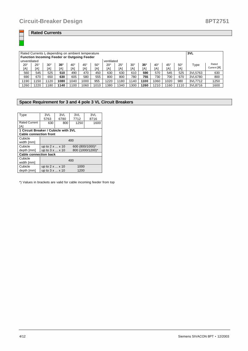
Rated Currents Rated Currents In depending on ambient temperature 3VL Function Incoming Feeder or Outgoing Feeder unventilated ventilated
20° 25° 30° 35° 40° 45° 50° 20° 25° 30° 35° 40° 45° 50° Type [A] [A] [A] [A] [A] [A] [A] [A] [A] [A] [A] [A] [A] [A]
Rated Current [A]
560 545 525 510 490 470 450 630 630 610 590 570 545 525 3VL5763 630 690 670 650 630 605 580 555 800 800 780 755 730 700 670 3VL6780 800
1190 1150 1120 1080 1040 1000 955 1220 1180 1140 1100 1060 1020 980 3VL7712 1250 1260 1220 1180 1140 1100 1060 1010 1380 1340 1300 1260 1210 1160 1110 3VL8716 1600
Space Requirement for 3 and 4 pole 3 VL Circuit Breakers Type
3VL 5763
3VL 6780
3VL 7712
3VL 8716
Rated Current [A]
630 800 1250 1600
1 Circuit Breaker / Cubicle with 3VL Cable connection front Cubicle width [mm] 400
Cubicle depth [mm]
up to 2 x ... x 10 600 (800/1000)* up to 3 x ... x 10 800 (1000/1200)*
Cable connection back Cubicle width [mm]
400
Cubicle depth [mm]
up to 2 x ... x 10 1000 up to 3 x ... x 10 1200
*) Values in brackets are valid for cable incoming feeder from top

8PT2751 Circuit-Breaker Design
Siemens SIVACON 8PT • 12/2003 4/13
Dimension drawings for bar connection 3WL up to 1600 A

Circuit-Breaker Design 8PT2751
4/14 Siemens SIVACON 8PT • 12/2003
Dimension drawings for bar connection 3WL 2000 A up to 3200 A

8PT2751 Circuit-Breaker Design
Siemens SIVACON 8PT • 12/2003 4/15
Dimension drawings for bar connection 3WL 4000 A and 5000 A

Circuit-Breaker Design 8PT2751
4/16 Siemens SIVACON 8PT • 12/2003
Dimension drawings for bar connection 3WL 6300 A
Related Documents