1 880GMH/U3S3 User Manual Version 1.0 Published February 2011 Copyright©2011 ASRock INC. All rights reserved.

Welcome message from author
This document is posted to help you gain knowledge. Please leave a comment to let me know what you think about it! Share it to your friends and learn new things together.
Transcript
11111
880GMH/U3S3
User Manual
Version 1.0Published February 2011
Copyright©2011 ASRock INC. All rights reserved.
1
Engl
ish
Copyright Notice:No part of this installation guide may be reproduced, transcribed, transmitted, or trans-lated in any language, in any form or by any means, except duplication of documentation by the purchaser for backup purpose, without written consent of ASRock Inc.Products and corporate names appearing in this guide may or may not be registered trademarks or copyrights of their respective companies, and are used only for identifi ca-tion or explanation and to the owners’ benefi t, without intent to infringe.
Disclaimer:Specifi cations and information contained in this guide are furnished for informational use only and subject to change without notice, and should not be constructed as a commit-ment by ASRock. ASRock assumes no responsibility for any errors or omissions that may appear in this guide. With respect to the contents of this guide, ASRock does not provide warranty of any kind, either expressed or implied, including but not limited to the implied warranties or condi-tions of merchantability or fi tness for a particular purpose. In no event shall ASRock, its directors, offi cers, employees, or agents be liable for any indirect, special, incidental, or consequential damages (including damages for loss of profi ts, loss of business, loss of data, interruption of business and the like), even if ASRock has been advised of the pos-sibility of such damages arising from any defect or error in the guide or product.
This device complies with Part 15 of the FCC Rules. Operation is subject to the following two conditions: (1) this device may not cause harmful interference, and (2) this device must accept any interference received, including interference that
may cause undesired operation.
CALIFORNIA, USA ONLYThe Lithium battery adopted on this motherboard contains Perchlorate, a toxic substance controlled in Perchlorate Best Management Practices (BMP) regulations passed by the California Legislature. When you discard the Lithium battery in California, USA, please follow the related regulations in advance.“Perchlorate Material-special handling may apply, see www.dtsc.ca.gov/hazardouswaste/perchlorate”
The terms HDMI™ and HDMI High-Defi nition Multimedia Interface, and the HDMI logo are trademarks or registered trademarks of HDMI Licensing LLC in the United States and other countries.

33333
ContentsContentsContentsContentsContents1.1.1.1.1. IntroductionIntroductionIntroductionIntroductionIntroduction ............................................................................................................................................................................................................................................................................................................ 5 5 5 5 5
1.1 Package Contents ..................................................................... 51.2 Specifications ............................................................................ 61.3 Motherboard Layout ................................................................. 121.4 I/O Panel .................................................................................... 13
2.2.2.2.2. InstallationInstallationInstallationInstallationInstallation ...................................................................................................................................................................................................................................................................................................................... 15 15 15 15 15Pre-installation Precautions ............................................................... 152.1 CPU Installation ......................................................................... 162.2 Installation of CPU Fan and Heatsink ....................................... 162.3 Installation of Memory Modules (DIMM) .................................... 172.4 Expansion Slots (PCI and PCI Express Slots) .......................... 192.5 Dual Monitor and Surround Display Features .......................... 202.6 ATITM Hybrid CrossFireXTM Operation Guide ............................. 232.7 ASRock Smart Remote Installation Guide ................................. 252.8 Jumpers Setup .......................................................................... 262.9 Onboard Headers and Connectors .......................................... 272.10 Serial ATAII (SATAII) / Serial ATA3 (SATA3) Hard Disks
Installation ................................................................................. 312.11 Hot Plug Function for SATAII / SATA3 HDDs ............................ 312.12 SATA / SATAII / SATA3 HDD Hot Plug Feature and Operation
Guide ....................................................................................... 312.13 Driver Installation Guide ............................................................ 342.14 Installing Windows® 7 / 7 64-bit / VistaTM / VistaTM 64-bit With
RAID Functions .......................................................................... 342.15 Installing Windows® 7 / 7 64-bit / VistaTM / VistaTM 64-bit / XP /
XP 64-bit Without RAID Functions ............................................. 352.15.1 Installing Windows® XP / XP 64-bit Without RAID
Functions ...................................................................... 352.15.2 Installing Windows® 7 / 7 64-bit / VistaTM / VistaTM 64-bit
Without RAID Functions ................................................ 352.16 Untied Overclocking Technology ................................................ 36

44444
3 .3 .3 .3 .3 . UEFI SUEFI SUEFI SUEFI SUEFI SETUP UTILITYETUP UTILITYETUP UTILITYETUP UTILITYETUP UTILITY ............................................................................................................................................................................................................................................................... 37 37 37 37 373.1 Introduction ................................................................................ 37
3.1.1 UEFI Menu Bar ................................................................ 373.1.2 Navigation Keys .............................................................. 38
3.2 Main Screen .............................................................................. 383.3 OC Tweaker Screen ................................................................... 393.4 Advanced Screen ....................................................................... 43
3.4.1 CPU Configuration ........................................................... 443.4.2 North Bridge Configuration ............................................... 453.4.3 South Bridge Configuration .............................................. 463.4.4 Storage Configuration ...................................................... 473.4.5 Super IO Configuration .................................................... 483.4.6 ACPI Configuration .......................................................... 493.4.7 USB Configuration ........................................................... 50
3.5 Hardware Health Event Monitoring Screen ................................. 513.6 Boot Screen .............................................................................. 523.7 Security Screen ......................................................................... 533.8 Exit Screen ................................................................................ 54
4 .4 .4 .4 .4 . Software SupportSoftware SupportSoftware SupportSoftware SupportSoftware Support ............................................................................................................................................................................................................................................................... 55 55 55 55 554.1 Install Operating System ........................................................... 554.2 Support CD Information .............................................................. 55
4.2.1 Running Support CD ........................................................ 554.2.2 Drivers Menu ................................................................... 554.2.3 Utilities Menu .................................................................. 554.2.4 Contact Information .......................................................... 55
55555
1.1.1.1.1. IntroductionIntroductionIntroductionIntroductionIntroductionThank you for purchasing ASRock 880GMH/U3S3 motherboard, a reliablemotherboard produced under ASRock’s consistently stringent quality control. It de-livers excellent performance with robust design conforming to ASRock’s commit-ment to quality and endurance.In this manual, chapter 1 and 2 contain introduction of the motherboard and step-by-stepguide to the hardware installation. Chapter 3 and 4 contain the configuration guide toBIOS setup and information of the Support CD.
Because the motherboard specifications and the BIOS software might beupdated, the content of this manual will be subject to change withoutnotice. In case any modifications of this manual occur, the updatedversion will be available on ASRock website without further notice. Youmay find the latest VGA cards and CPU support lists on ASRock websiteas well. ASRock website http://www.asrock.comIf you require technical support related to this motherboard, please visitour website for specific information about the model you are using.www.asrock.com/support/index.asp
1.11 .11 .11 .11 .1 PPPPPackackackackackage Contentsage Contentsage Contentsage Contentsage ContentsASRock 880GMH/U3S3 Motherboard
(Micro ATX Form Factor: 9.6-in x 9.0-in, 24.4 cm x 22.9 cm)ASRock 880GMH/U3S3 Quick Installation GuideASRock 880GMH/U3S3 Support CD2 x Serial ATA (SATA) Data Cables (Optional)1 x I/O Panel Shield

66666
1.21.21.21.21.2 SpecificationsSpecificationsSpecificationsSpecificationsSpecifications
Platform - Micro ATX Form Factor: 9.6-in x 9.0-in, 24.4 cm x 22.9 cm- All Solid Capacitor design
CPU - Support for Socket AM3+ processors- Support for Socket AM3 processors: AMD PhenomTM II X6 / X4 / X3 / X2 (except 920 / 940) / Athlon II X4 / X3 / X2 / Sempron processors- Supports 8-Core CPU- Supports AMD OverDriveTM with ACC feature (Advanced Clock Calibration)- Supports AMD’s Cool ‘n’ QuietTM Technology- FSB 2600 MHz (5.2 GT/s)- Supports Untied Overclocking Technology (see CAUTION 1)- Supports Hyper-Transport 3.0 (HT 3.0) Technology
Chipset - Northbridge: AMD 880G- Southbridge: AMD SB710
Memory - Dual Channel DDR3 Memory Technology (see CAUTION 2)- 4 x DDR3 DIMM slots- Support DDR3 1866(OC)/1800(OC)/1600(OC)/1333/1066/800 non-ECC, un-buffered memory (see CAUTION 3)- Max. capacity of system memory: 32GB (see CAUTION 4)
Expansion Slot - 1 x PCI Express 2.0 x16 slot (blue @ x16 mode)- 1 x PCI Express 2.0 x1 slot- 2 x PCI slots- Supports ATITM Hybrid CrossFireXTM
Graphics - Integrated AMD Radeon HD 4250 graphics- DX10.1 class iGPU, Shader Model 4.1- Max. shared memory 512MB (see CAUTION 5)- Three VGA Output options: D-Sub, DVI-D and HDMI- Supports HDMI Technology with max. resolution up to 1920x1200 (1080P)- Supports Dual-link DVI with max. resolution up to 2560x1600 @ 75Hz- Supports D-Sub with max. resolution up to 2048x1536 @ 85Hz- Supports HDCP function with DVI and HDMI ports- Supports Full HD 1080p Blu-ray (BD) / HD-DVD playback with DVI and HDMI ports
77777
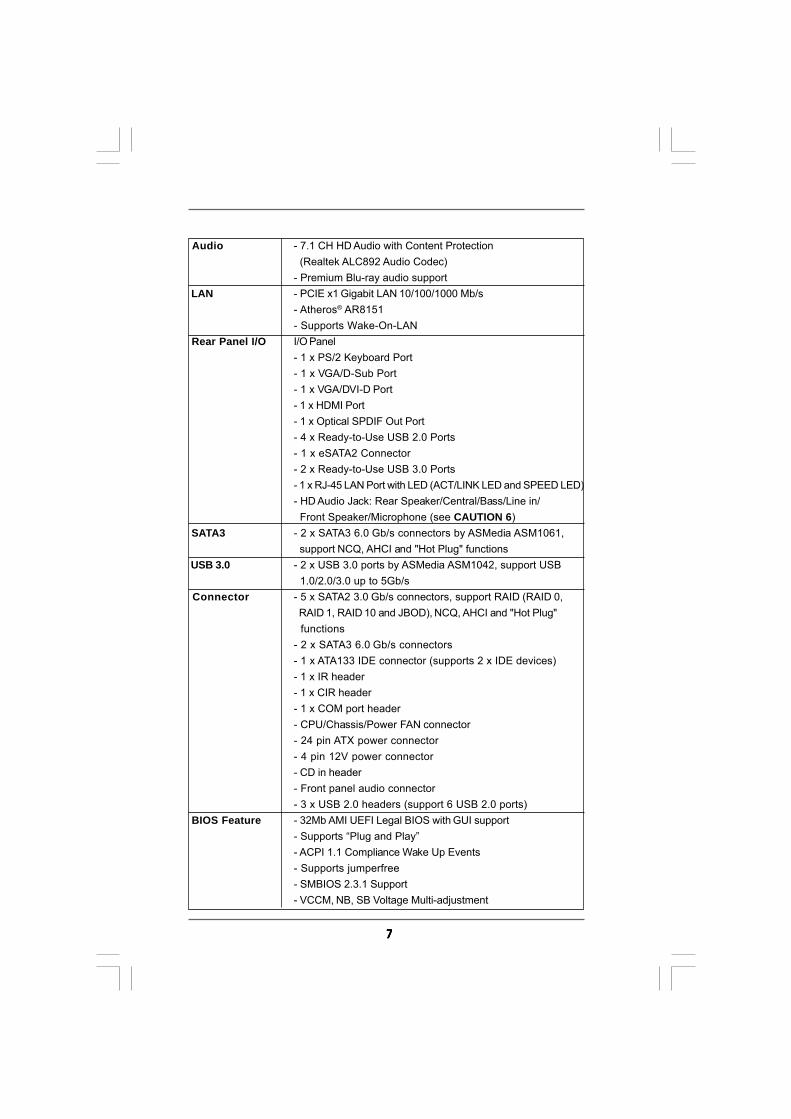
Audio - 7.1 CH HD Audio with Content Protection (Realtek ALC892 Audio Codec)- Premium Blu-ray audio support
LAN - PCIE x1 Gigabit LAN 10/100/1000 Mb/s- Atheros® AR8151- Supports Wake-On-LAN
Rear Panel I/O I/O Panel- 1 x PS/2 Keyboard Port- 1 x VGA/D-Sub Port- 1 x VGA/DVI-D Port- 1 x HDMI Port- 1 x Optical SPDIF Out Port- 4 x Ready-to-Use USB 2.0 Ports- 1 x eSATA2 Connector- 2 x Ready-to-Use USB 3.0 Ports- 1 x RJ-45 LAN Port with LED (ACT/LINK LED and SPEED LED)- HD Audio Jack: Rear Speaker/Central/Bass/Line in/ Front Speaker/Microphone (see CAUTION 6)
SATA3 - 2 x SATA3 6.0 Gb/s connectors by ASMedia ASM1061, support NCQ, AHCI and "Hot Plug" functions
USB 3.0 - 2 x USB 3.0 ports by ASMedia ASM1042, support USB 1.0/2.0/3.0 up to 5Gb/s
Connector - 5 x SATA2 3.0 Gb/s connectors, support RAID (RAID 0, RAID 1, RAID 10 and JBOD), NCQ, AHCI and "Hot Plug" functions- 2 x SATA3 6.0 Gb/s connectors- 1 x ATA133 IDE connector (supports 2 x IDE devices)- 1 x IR header- 1 x CIR header- 1 x COM port header- CPU/Chassis/Power FAN connector- 24 pin ATX power connector- 4 pin 12V power connector- CD in header- Front panel audio connector- 3 x USB 2.0 headers (support 6 USB 2.0 ports)
BIOS Feature - 32Mb AMI UEFI Legal BIOS with GUI support- Supports “Plug and Play”- ACPI 1.1 Compliance Wake Up Events- Supports jumperfree- SMBIOS 2.3.1 Support- VCCM, NB, SB Voltage Multi-adjustment
88888
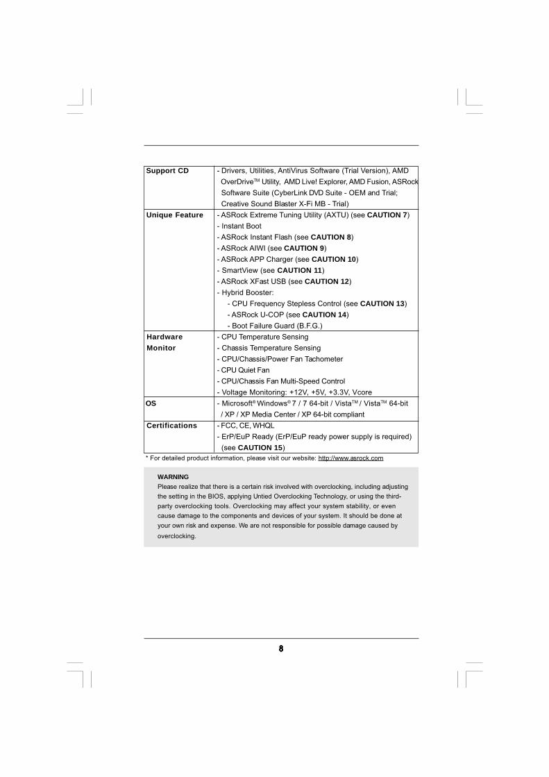
Support CD - Drivers, Utilities, AntiVirus Software (Trial Version), AMD OverDriveTM Utility, AMD Live! Explorer, AMD Fusion, ASRock Software Suite (CyberLink DVD Suite - OEM and Trial; Creative Sound Blaster X-Fi MB - Trial)
Unique Feature - ASRock Extreme Tuning Utility (AXTU) (see CAUTION 7)- Instant Boot- ASRock Instant Flash (see CAUTION 8)- ASRock AIWI (see CAUTION 9)- ASRock APP Charger (see CAUTION 10)- SmartView (see CAUTION 11)- ASRock XFast USB (see CAUTION 12)- Hybrid Booster:
- CPU Frequency Stepless Control (see CAUTION 13)- ASRock U-COP (see CAUTION 14)- Boot Failure Guard (B.F.G.)
Hardware - CPU Temperature Sensing Monitor - Chassis Temperature Sensing
- CPU/Chassis/Power Fan Tachometer- CPU Quiet Fan- CPU/Chassis Fan Multi-Speed Control- Voltage Monitoring: +12V, +5V, +3.3V, Vcore
OS - Microsoft® Windows® 7 / 7 64-bit / VistaTM / VistaTM 64-bit / XP / XP Media Center / XP 64-bit compliant
Certifications - FCC, CE, WHQL- ErP/EuP Ready (ErP/EuP ready power supply is required) (see CAUTION 15)
* For detailed product information, please visit our website: http://www.asrock.com
WARNINGPlease realize that there is a certain risk involved with overclocking, including adjustingthe setting in the BIOS, applying Untied Overclocking Technology, or using the third-party overclocking tools. Overclocking may affect your system stability, or evencause damage to the components and devices of your system. It should be done atyour own risk and expense. We are not responsible for possible damage caused byoverclocking.

99999
CAUTION!1. This motherboard supports Untied Overclocking Technology. Please read “Un-
tied Overclocking Technology” on page 36 for details.2. This motherboard supports Dual Channel Memory Technology. Before you
implement Dual Channel Memory Technology, make sure to read theinstallation guide of memory modules on page 17 for proper installation.
3. Whether 1866/1800/1600MHz memory speed is supported depends on theAM3/AM3+ CPU you adopt. If you want to adopt DDR3 1866/1800/1600memory module on this motherboard, please refer to the memory supportlist on our website for the compatible memory modules.ASRock website http://www.asrock.com
4. Due to the operating system limitation, the actual memory size may beless than 4GB for the reservation for system usage under Windows® 7 /VistaTM / XP. For Windows® OS with 64-bit CPU, there is no such limitation.
5. The maximum shared memory size is defined by the chipset vendor andis subject to change. Please check AMD website for the latest information.
6. For microphone input, this motherboard supports both stereo and mono modes.For audio output, this motherboard supports 2-channel, 4-channel, 6-channel,and 8-channel modes. Please check the table on page 13 for proper connection.
7. ASRock Extreme Tuning Utility (AXTU) is an all-in-one tool to ne-tunedifferent system functions in a user-friendly interface, which is includingHardware Monitor, Fan Control, Overclocking, OC DNA and IES. In Hard-ware Monitor, it shows the major readings of your system. In Fan Control,it shows the fan speed and temperature for you to adjust. In Overclocking,you are allowed to overclock CPU frequency for optimal systemperformance. In OC DNA, you can save your OC settings as a profile andshare with your friends. Your friends then can load the OC profile to theirown system to get the same OC settings. In IES (Intelligent EnergySaver), the voltage regulator can reduce the number of output phases toimprove efficiency when the CPU cores are idle without sacrificingcomputing performance. Please visit our website for the operation proce-dures of ASRock Extreme Tuning Utility (AXTU).ASRock website: http://www.asrock.com
8. ASRock Instant Flash is a BIOS flash utility embedded in Flash ROM.This convenient BIOS update tool allows you to update system BIOSwithout entering operating systems first like MS-DOS or Windows®. Withthis utility, you can press <F6> key during the POST or press <F2> key toBIOS setup menu to access ASRock Instant Flash. Just launch this tooland save the new BIOS file to your USB flash drive, floppy disk or harddrive, then you can update your BIOS only in a few clicks without prepar-ing an additional floppy diskette or other complicated flash utility. Pleasebe noted that the USB flash drive or hard drive must use FAT32/16/12 filesystem.
1010101010
9. To experience intuitive motion controlled games is no longer only availableat Wii. ASRock AIWI utility introduces a new way of PC gaming operation.ASRock AIWI is the world's first utility to turn your iPhone/iPod touch asa game joystick to control your PC games. All you have to do is just toinstall the ASRock AIWI utility either from ASRock official website orASRock software support CD to your motherboard, and also download thefree AIWI Lite from App store to your iPhone/iPod touch. Connecting yourPC and apple devices via Bluetooth or WiFi networks, then you can startexperiencing the exciting motion controlled games. Also, please do notforget to pay attention to ASRock official website regularly, we willcontinuously provide you the most up-do-date supported games!ASRock website: http://www.asrock.com/Feature/Aiwi/index.asp
10. If you desire a faster, less restricted way of charging your Apple devices,such as iPhone/iPod/iPad Touch, ASRock has prepared a wonderfulsolution for you - ASRock APP Charger. Simply installing the APP Chargerdriver, it makes your iPhone charged much quickly from your computerand up to 40% faster than before. ASRock APP Charger allows you toquickly charge many Apple devices simultaneously and even supportscontinuous charging when your PC enters into Standby mode (S1), Sus-pend to RAM (S3), hibernation mode (S4) or power off (S5). With APPCharger driver installed, you can easily enjoy the marvelous chargingexperience than ever.ASRock website: http://www.asrock.com/Feature/AppCharger/index.asp
11. SmartView, a new function of internet browser, is the smart start page forIE that combines your most visited web sites, your history, your Facebookfriends and your real-time newsfeed into an enhanced view for a morepersonal Internet experience. ASRock motherboards are exclusivelyequipped with the SmartView utility that helps you keep in touch withfriends on-the-go. To use SmartView feature, please make sure your OSversion is Windows® 7 / 7 64 bit / VistaTM / VistaTM 64 bit, and your browserversion is IE8.ASRock website: http://www.asrock.com/Feature/SmartView/index.asp
12. ASRock XFast USB can boost USB storage device performance. Theperformance may depend on the property of the device.
13. Although this motherboard offers stepless control, it is not recommendedto perform over-clocking. Frequencies other than the recommended CPUbus frequencies may cause the instability of the system or damage theCPU.
14. While CPU overheat is detected, the system will automatically shutdown.Before you resume the system, please check if the CPU fan on themotherboard functions properly and unplug the power cord, then plug itback again. To improve heat dissipation, remember to spray thermalgrease between the CPU and the heatsink when you install the PC system.
1111111111
15. EuP, stands for Energy Using Product, was a provision regulated byEuropean Union to define the power consumption for the completed system.According to EuP, the total AC power of the completed system shall beunder 1.00W in off mode condition. To meet EuP standard, an EuP readymotherboard and an EuP ready power supply are required. According toIntel’s suggestion, the EuP ready power supply must meet the standard of5v standby power efficiency is higher than 50% under 100 mA currentconsumption. For EuP ready power supply selection, we recommend youchecking with the power supply manufacturer for more details.

1212121212
1.3 Motherboard Layout1.3 Motherboard Layout1.3 Motherboard Layout1.3 Motherboard Layout1.3 Motherboard Layout
1 CPU Fan Connector (CPU_FAN1) 18 SATAII Connector (SATAII_2 (PORT 1), Blue) 2 ATX 12V Power Connector (ATX12V1) 19 SATAII Connector (SATAII_1 (PORT 0), Blue) 3 CPU Heatsink Retention Module 20 System Panel Header (PANEL1, White) 4 AM3+ CPU Socket 21 Chassis Speaker Header 5 2 x 240-pin DDR3 DIMM Slots (SPEAKER 1, White)
(Dual Channel A: DDR3_A1, DDR3_B1; Blue) 22 USB 2.0 Header (USB10_11, Blue) 6 2 x 240-pin DDR3 DIMM Slots 23 Clear CMOS Jumper (CLRCMOS1)
(Dual Channel B: DDR3_A2, DDR3_B2; White) 24 SATA3 Connector (SATA3_1, White) 7 ATX Power Connector (ATXPWR1) 25 SATA3 Connector (SATA3_2, White) 8 Primary IDE Connector (IDE1, Blue) 26 Infrared Module Header (IR1) 9 Consumer Infrared Module Header (CIR1) 27 Serial Port Connector (COM1)10 Chassis Fan Connector (CHA_FAN1) 28 PCI Slots (PCI1-2)11 USB 2.0 Header (USB6_7, Blue) 29 PCI Express 2.0 x16 Slot (PCIE2; Blue)12 USB 2.0 Header (USB8_9, Blue) 30 PCI Express 2.0 x1 Slot (PCIE1; White)13 Southbridge Controller 31 Power Fan Connector (PWR_FAN1)14 SPI Flash Memory (32Mb) 32 Front Panel Audio Header15 SATAII Connector (SATAII_5 (PORT 4), Blue) (HD_AUDIO1, White)16 SATAII Connector (SATAII_4 (PORT 3), Blue) 33 Internal Audio Connector: CD1 (Black)17 SATAII Connector (SATAII_3 (PORT 2), Blue) 34 Northbridge Controller
SuperI/O
CMOS
BATTERY
AT
XP
WR
1
AMD880G
Chipset
ATX12V1
COM1
PCIE1
PCI1
PCI2
LAN
AUDIOCODEC
1
CLRCMOS1
1
CP
U_
FA
N1
HDLED RESET
PLED PWRBTN
1
PANEL 1
CH
A_
FA
N1
SPEAKER1
1
HD
_A
UD
IO1
1
24
.4c
m(9
.6-i
n)
22.9cm (9.0-in)
6
7
1 2 43 5
8
9101112
13
14
15
161718192021222324252627
28
29
30
31
32
32MbBIOS
IR11
AMDSB710
Chipset
PCIE2
33
FS
B8
00
DD
R3
_A
1(6
4b
it,2
40
-pin
mo
du
le)
DD
R3
_B
1(6
4b
it,2
40
-pin
mo
du
le)
FS
B8
00
DD
R3
_A
2(6
4b
it,2
40
-pin
mo
du
le)
DD
R3
_B
2(6
4b
it,2
40
-pin
mo
du
le)
SATAII_1(
SATAII_2 SATAII_3 SATAII_4 SATAII_5PORT 0) (PORT 1) (PORT 2) (PORT 3) (PORT 4)
34
USB 2.0T: USB2B: USB3
PS
2K
ey
bo
ard
VG
A1
DV
I_C
ON
1
HD
MI1
To
p:
CT
RB
AS
S
Ce
nte
r:
RE
AR
SP
K
Bo
tto
m:
Op
tic
al
SP
DIF
To
p:
LIN
EIN
Ce
nte
r:
FR
ON
T
Bo
tto
m:
MIC
IN
RJ
-45
LA
N
eS
AT
A1
USB 2.0T: USB4B: USB5
1 11
US
B1
0_
11
US
B8
_9
US
B6
_7
PW
R_
FA
N1
DX10.1
880GMH/U3S3
Support 8-Core CPU
ErP/EuP Ready
US
B3.
0Designed in Taipei
RoHS
AM
3+
HT
3.0
Phen
omII
DD
R3
18
66
Du
alC
ha
nn
el
FS
B2
.6G
Hz
CD1
IDE1
USB 3.0T: USB0B: USB1
CIR
1
1
SATA3_2 SATA3_1
SATA3 6Gb/s
SOCKETAM
3b
1313131313
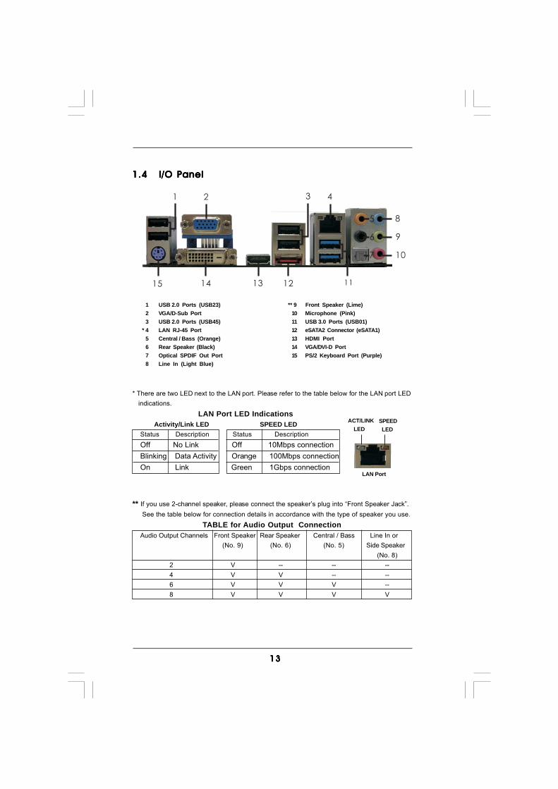
1.41.41.41.41.4 I/O PanelI/O PanelI/O PanelI/O PanelI/O Panel
** If you use 2-channel speaker, please connect the speaker’s plug into “Front Speaker Jack”. See the table below for connection details in accordance with the type of speaker you use.
TABLE for Audio Output ConnectionAudio Output Channels Front Speaker Rear Speaker Central / Bass Line In or
(No. 9) (No. 6) (No. 5) Side Speaker(No. 8)
2 V -- -- --4 V V -- --6 V V V --8 V V V V
LAN Port
ACT/LINK LED
SPEED LED
* There are two LED next to the LAN port. Please refer to the table below for the LAN port LED indications.
LAN Port LED Indications Activity/Link LED SPEED LEDStatus Description Status DescriptionOff No Link Off 10Mbps connectionBlinking Data Activity Orange 100Mbps connectionOn Link Green 1Gbps connection
1 USB 2.0 Ports (USB23) ** 9 Front Speaker (Lime)2 VGA/D-Sub Port 10 Microphone (Pink)3 USB 2.0 Ports (USB45) 11 USB 3.0 Ports (USB01)
* 4 LAN RJ-45 Port 12 eSATA2 Connector (eSATA1)5 Central / Bass (Orange) 13 HDMI Port6 Rear Speaker (Black) 14 VGA/DVI-D Port7 Optical SPDIF Out Port 15 PS/2 Keyboard Port (Purple)8 Line In (Light Blue)
1 2
5
3
6
7
8
9
10
111213
4
1415

1414141414
To enable Multi-Streaming function, you need to connect a front panel audio cable to the front panel audio header. After restarting your computer, you will find “Mixer” tool on your system. Please select “Mixer ToolBox” , click “Enable playback multi-streaming”, and click
“ok”. Choose “2CH”, “4CH”, “6CH”, or “8CH” and then you are allowed to select “Realtek HDA Primary output” to use Rear Speaker, Central/Bass, and Front Speaker, or select “Realtek HDA Audio 2nd output” to use front panel audio.
1515151515
2.2.2.2.2. InstallationInstallationInstallationInstallationInstallationThis is a Micro ATX Form Factor (9.6-in x 9.0-in, 24.4 cm x 22.9 cm) motherboard.Before you install the motherboard, study the configuration of your chassis to en-sure that the motherboard fits into it.
Pre-installation PrecautionsPre-installation PrecautionsPre-installation PrecautionsPre-installation PrecautionsPre-installation PrecautionsTake note of the following precautions before you install motherboardcomponents or change any motherboard settings.
Before you install or remove any component, ensure that thepower is switched off or the power cord is detached from thepower supply. Failure to do so may cause severe damage to themotherboard, peripherals, and/or components.
1. Unplug the power cord from the wall socket before touching anycomponent.
2. To avoid damaging the motherboard components due to staticelectricity, NEVER place your motherboard directly on the carpet orthe like. Also remember to use a grounded wrist strap or touch asafety grounded object before you handle components.
3. Hold components by the edges and do not touch the ICs.4. Whenever you uninstall any component, place it on a grounded anti-
static pad or in the bag that comes with the component.5. When placing screws into the screw holes to secure the motherboard
to the chassis, please do not over-tighten the screws! Doing so maydamage the motherboard.
1616161616
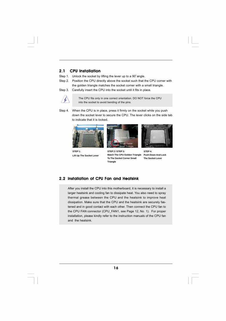
2.12.12.12.12.1 CPU InstallationCPU InstallationCPU InstallationCPU InstallationCPU InstallationStep 1. Unlock the socket by lifting the lever up to a 90o angle.Step 2. Position the CPU directly above the socket such that the CPU corner with
the golden triangle matches the socket corner with a small triangle.Step 3. Carefully insert the CPU into the socket until it fits in place.
The CPU fits only in one correct orientation. DO NOT force the CPUinto the socket to avoid bending of the pins.
Step 4. When the CPU is in place, press it firmly on the socket while you pushdown the socket lever to secure the CPU. The lever clicks on the side tabto indicate that it is locked.
2.22.22.22.22.2 Installation of CPU Fan and HeatsinkInstallation of CPU Fan and HeatsinkInstallation of CPU Fan and HeatsinkInstallation of CPU Fan and HeatsinkInstallation of CPU Fan and Heatsink
After you install the CPU into this motherboard, it is necessary to install alarger heatsink and cooling fan to dissipate heat. You also need to spraythermal grease between the CPU and the heatsink to improve heatdissipation. Make sure that the CPU and the heatsink are securely fas-tened and in good contact with each other. Then connect the CPU fan tothe CPU FAN connector (CPU_FAN1, see Page 12, No. 1). For properinstallation, please kindly refer to the instruction manuals of the CPU fanand the heatsink.
STEP 1:
Lift Up The Socket Lever
STEP 2 / STEP 3:Match The CPU Golden TriangleTo The Socket Corner SmallTriangle
STEP 4:Push Down And LockThe Socket Lever
Lever 90° Up
CPU Golden Triangle
Socker CornerSmall Triangle
1717171717
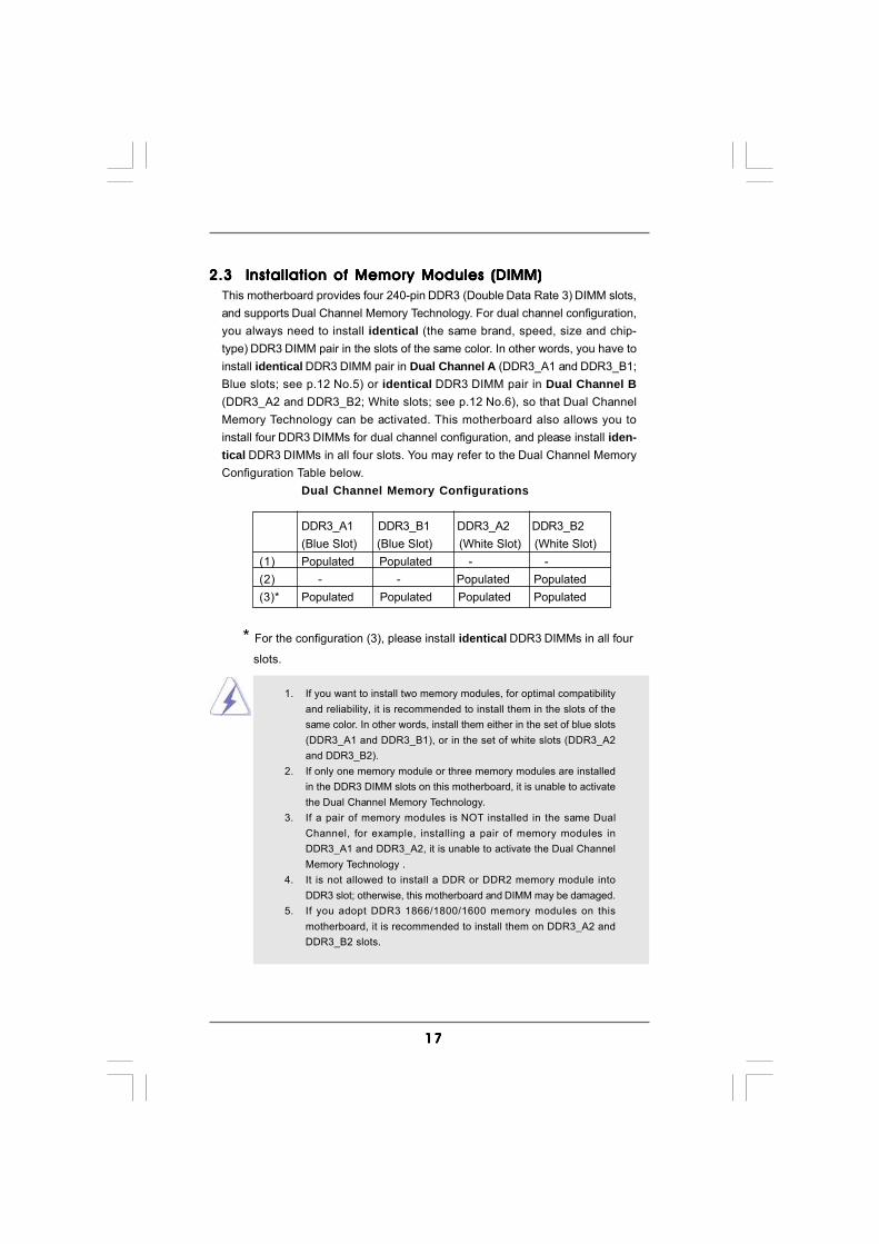
2.3 Installation of Memory Modules (DIMM)2.3 Installation of Memory Modules (DIMM)2.3 Installation of Memory Modules (DIMM)2.3 Installation of Memory Modules (DIMM)2.3 Installation of Memory Modules (DIMM)This motherboard provides four 240-pin DDR3 (Double Data Rate 3) DIMM slots,and supports Dual Channel Memory Technology. For dual channel configuration,you always need to install identical (the same brand, speed, size and chip-type) DDR3 DIMM pair in the slots of the same color. In other words, you have toinstall identical DDR3 DIMM pair in Dual Channel A (DDR3_A1 and DDR3_B1;Blue slots; see p.12 No.5) or identical DDR3 DIMM pair in Dual Channel B(DDR3_A2 and DDR3_B2; White slots; see p.12 No.6), so that Dual ChannelMemory Technology can be activated. This motherboard also allows you toinstall four DDR3 DIMMs for dual channel configuration, and please install iden-tical DDR3 DIMMs in all four slots. You may refer to the Dual Channel MemoryConfiguration Table below.
Dual Channel Memory Configurations
DDR3_A1 DDR3_B1 DDR3_A2 DDR3_B2(Blue Slot) (Blue Slot) (White Slot) (White Slot)
(1) Populated Populated - -(2) - - Populated Populated(3)* Populated Populated Populated Populated
* For the configuration (3), please install identical DDR3 DIMMs in all four
slots.
1. If you want to install two memory modules, for optimal compatibilityand reliability, it is recommended to install them in the slots of thesame color. In other words, install them either in the set of blue slots(DDR3_A1 and DDR3_B1), or in the set of white slots (DDR3_A2and DDR3_B2).
2. If only one memory module or three memory modules are installedin the DDR3 DIMM slots on this motherboard, it is unable to activatethe Dual Channel Memory Technology.
3. If a pair of memory modules is NOT installed in the same DualChannel, for example, installing a pair of memory modules inDDR3_A1 and DDR3_A2, it is unable to activate the Dual ChannelMemory Technology .
4. It is not allowed to install a DDR or DDR2 memory module intoDDR3 slot; otherwise, this motherboard and DIMM may be damaged.
5. If you adopt DDR3 1866/1800/1600 memory modules on thismotherboard, it is recommended to install them on DDR3_A2 andDDR3_B2 slots.

1818181818
notch
break
notchbreak
Installing a DIMMInstalling a DIMMInstalling a DIMMInstalling a DIMMInstalling a DIMM
Please make sure to disconnect power supply before adding orremoving DIMMs or the system components.
Step 1. Unlock a DIMM slot by pressing the retaining clips outward.Step 2. Align a DIMM on the slot such that the notch on the DIMM matches the break
on the slot.
The DIMM only fits in one correct orientation. It will cause permanentdamage to the motherboard and the DIMM if you force the DIMM into the slotat incorrect orientation.
Step 3. Firmly insert the DIMM into the slot until the retaining clips at both ends fullysnap back in place and the DIMM is properly seated.

1919191919
2.4 Expansion Slots (PCI and PCI Express Slots)2.4 Expansion Slots (PCI and PCI Express Slots)2.4 Expansion Slots (PCI and PCI Express Slots)2.4 Expansion Slots (PCI and PCI Express Slots)2.4 Expansion Slots (PCI and PCI Express Slots)There are 2 PCI slots and 2 PCI Express slots on this motherboard.PCI Slots: PCI slots are used to install expansion cards that have the 32-bit PCI
interface.PCIE Slots:
PCIE1 (PCIE x1 slot; White) is used for PCI Express cards with x1 lanewidth cards, such as Gigabit LAN card and SATA2 card.PCIE2 (PCIE x16 slot; Blue) is used for PCI Express x16 lane widthgraphics cards.
Installing an expansion cardInstalling an expansion cardInstalling an expansion cardInstalling an expansion cardInstalling an expansion cardStep 1. Before installing the expansion card, please make sure that the power
supply is switched off or the power cord is unplugged. Please read thedocumentation of the expansion card and make necessary hardwaresettings for the card before you start the installation.
Step 2. Remove the system unit cover (if your motherboard is already installed in achassis).
Step 3. Remove the bracket facing the slot that you intend to use. Keep the screwsfor later use.
Step 4. Align the card connector with the slot and press firmly until the card iscompletely seated on the slot.
Step 5. Fasten the card to the chassis with screws.Step 6. Replace the system cover.
2020202020
2. If you have installed onboard VGA driver from our support CD to your system already, you can freely enjoy the benefits of dual monitor function after your system boots. If you haven’t installed onboard VGA driver yet, please install onboard VGA driver from our support CD to your system and restart your computer. Then you can start to use dual monitor function on this motherboard.
1. DVI-D and HDMI ports cannot function at the same time. When one of them is enabled, the other one will be disabled.2. When you playback HDCP-protected video from Blu-ray (BD) or
HD-DVD disc, the content will be displayed only in one of the two monitors instead of both monitors.
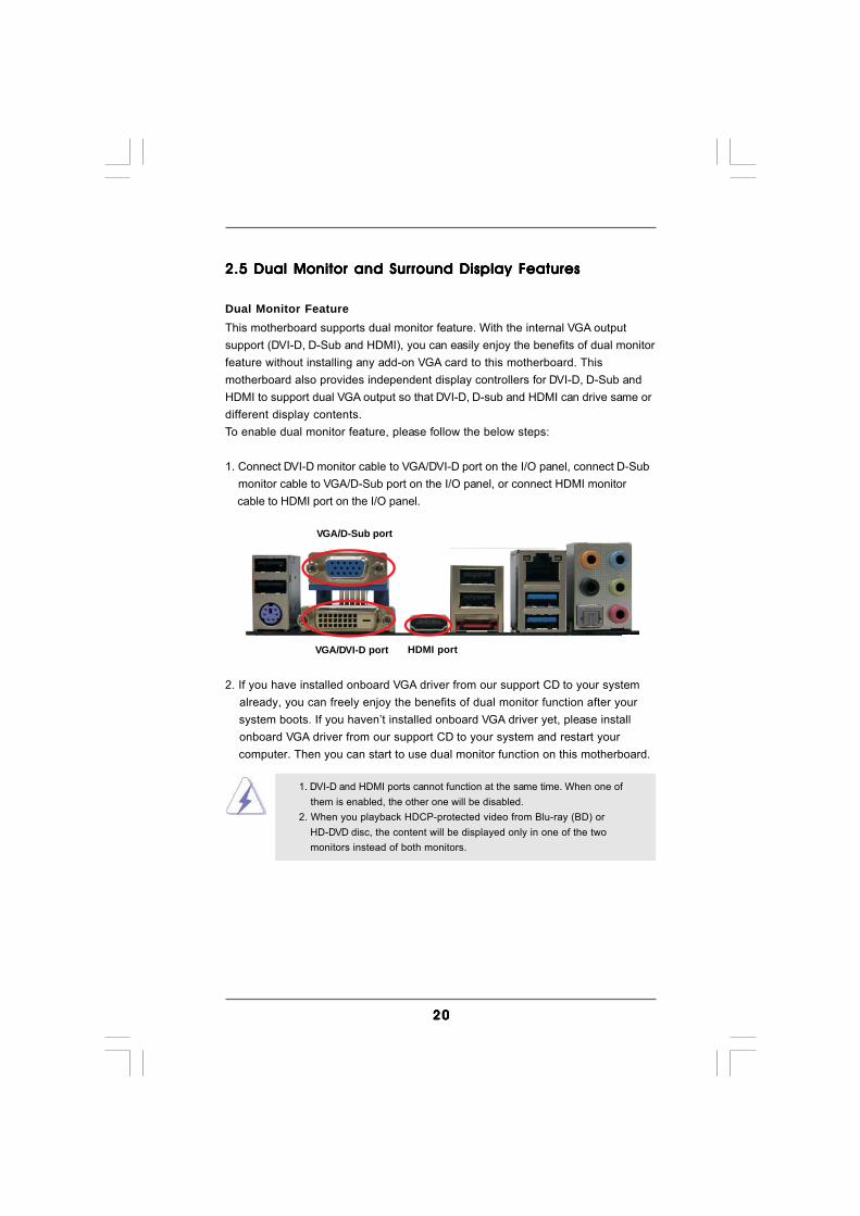
2.5 Dual Monitor and Surround Display Features2.5 Dual Monitor and Surround Display Features2.5 Dual Monitor and Surround Display Features2.5 Dual Monitor and Surround Display Features2.5 Dual Monitor and Surround Display Features
Dual Monitor FeatureThis motherboard supports dual monitor feature. With the internal VGA outputsupport (DVI-D, D-Sub and HDMI), you can easily enjoy the benefits of dual monitorfeature without installing any add-on VGA card to this motherboard. Thismotherboard also provides independent display controllers for DVI-D, D-Sub andHDMI to support dual VGA output so that DVI-D, D-sub and HDMI can drive same ordifferent display contents.To enable dual monitor feature, please follow the below steps:
1. Connect DVI-D monitor cable to VGA/DVI-D port on the I/O panel, connect D-Sub monitor cable to VGA/D-Sub port on the I/O panel, or connect HDMI monitor cable to HDMI port on the I/O panel.
VGA/DVI-D port HDMI port
VGA/D-Sub port

2121212121
Surround Display FeatureThis motherboard supports surround display upgrade. With the internal VGAoutput support (DVI-D, D-Sub and HDMI) and external add-on PCI Express VGAcards, you can easily enjoy the benefits of surround display feature.Please refer to the following steps to set up a surround display environment:
1. Install the ATITM PCI Express VGA card on PCIE2 slot. Please refer to page 19 for proper expansion card installation procedures for details.2. Connect DVI-D monitor cable to VGA/DVI-D port on the I/O panel, connect D-Sub monitor cable to VGA/D-Sub port on the I/O panel, or connect HDMI monitor cable to HDMI port on the I/O panel. Then connect other monitor cables to the corresponding connectors of the add-on PCI Express VGA card on PCIE2 slot.3. Boot your system. Press <F2> to enter UEFI setup. Enter “Share Memory” option to adjust the memory capability to [32MB], [64MB], [128MB] [256MB] or [512MB] to enable the function of VGA/D-sub. Please make sure that the value you select is less than the total capability of the system memory. If you do not adjust the UEFI setup, the default value of “Share Memory”, [Auto], will disable VGA/D-Sub function when the add-on VGA card is inserted to this motherboard.4. Install the onboard VGA driver and the add-on PCI Express VGA card driver to your system. If you have installed the drivers already, there is no need to install them again.5. Set up a multi-monitor display.
For Windows® XP / XP 64-bit OS:Right click the desktop, choose “Properties”, and select the “Settings” tabso that you can adjust the parameters of the multi-monitor according to thesteps below.A. Click the “Identify” button to display a large number on each monitor.B. Right-click the display icon in the Display Properties dialog that you wish to be your primary monitor, and then select “Primary”. When you use multiple monitors with your card, one monitor will always be Primary, and all additional monitors will be designated as Secondary.C. Select the display icon identified by the number 2.D. Click “Extend my Windows desktop onto this monitor”.E. Right-click the display icon and select “Attached”, if necessary.F. Set the “Screen Resolution” and “Color Quality” as appropriate for the second monitor. Click “Apply” or “OK” to apply these new values.G. Repeat steps C through E for the diaplay icon identified by the number one, two, three and four.
2222222222
HDCP FunctionHDCP function is supported on this motherboard. To use HDCPfunction with this motherboard, you need to adopt the monitor thatsupports HDCP function as well. Therefore, you can enjoy thesuperior display quality with high-definition HDCP encryptioncontents. Please refer to below instruction for more details aboutHDCP function.
What is HDCP?HDCP stands for High-Bandwidth Digital Content Protection, aspecification developed by Intel® for protecting digital entertainmentcontent that uses the DVI interface. HDCP is a copy protectionscheme to eliminate the possibility of intercepting digital datamidstream between the video source, or transmitter - such as acomputer, DVD player or set-top box - and the digital display, orreceiver - such as a monitor, television or projector. In other words,HDCP specification is designed to protect the integrity of content as itis being transmitted.
Products compatible with the HDCP scheme such as DVD players,satellite and cable HDTV set-top-boxes, as well as few entertain-ment PCs requires a secure connection to a compliant display. Dueto the increase in manufacturers employing HDCP in their equipment,it is highly recommended that the HDTV or LCD monitor you purchaseis compatible.
For Windows® 7 / 7 64-bit / VistaTM / VistaTM 64-bit OS:Right click the desktop, choose “Personalize”, and select the “DisplaySettings” tab so that you can adjust the parameters of the multi-monitoraccording to the steps below.A. Click the number ”2” icon.B. Click the items “This is my main monitor” and “Extend the desktop onto this monitor”.C. Click “OK” to save your change.D. Repeat steps A through C for the display icon identified by the number three and four.
6. Use Surround Display. Click and drag the display icons to positions representing the physical setup of your monitors that you would like to use. The placement of display icons determines how you move items from one monitor to another.

2323232323
2.62.62.62.62.6 AAAAATITITITITITMTMTMTMTM Hybrid CrossF Hybrid CrossF Hybrid CrossF Hybrid CrossF Hybrid CrossFireXireXireXireXireXTMTMTMTMTM Operation Guide Operation Guide Operation Guide Operation Guide Operation GuideThis motherboard supports ATITM Hybrid CrossFireXTM feature. ATITM HybridCrossFireXTM brings multi-GPU performance capabilities by enabling an AMD 880Gintegrated graphics processor and a discrete graphics processor to operatesimultaneously with combined output to a single display for blisteringly-fast framerates. Currently, ATITM Hybrid CrossFireXTM Technology is only supported withWindows® VistaTM / 7 OS, and is not available with Windows® XP OS. In the future,ATITM Hybrid CrossFireXTM may be supported with Windows® XP OS.
Enjoy the benefit of AEnjoy the benefit of AEnjoy the benefit of AEnjoy the benefit of AEnjoy the benefit of ATITITITITITMTMTMTMTM Hybrid CrossF Hybrid CrossF Hybrid CrossF Hybrid CrossF Hybrid CrossFireXireXireXireXireXTMTMTMTMTM
Step 1. Install one compatible PCI Express graphics card to PCIE2 slot (blue). Forthe proper installation procedures, please refer to section “Expansion Slots”.
Step 2. Connect the monitor cable to the correspondent connector on the PCIExpress graphics card on PCIE2 slot.
Step 3. Boot your system. Press <F2> to enter UEFI setup. Enter “Advanced”screen, and enter “North Bridge Configuration”. Then set the option “Sur-round View” to [Enabled].
Step 4. Boot into OS. Please remove the ATITM driver if you have any VGA driverinstalled in your system.
Step 5. Install the onboard VGA driver from our support CD to your system for boththe onboard VGA and the discrete graphics card.
Step 6. Restart your computer. Then you will find “ATI Catalyst Control Center” onyour Windows® taskbar.
ATI Catalyst Control Center
Vendor Chipset Model DriverATI RADEON HD2400XT POWERCOLOR HD2400 XT Support CD 8.71
256MB DDR3RADEON HD3450 POWERCOLOR AX3450 Support CD 8.71
256MD2-S
What does an ATITM Hybrid CrossFireXTM system include?An ATITM Hybrid CrossFireXTM system includes an ATITM RadeonTM 2400 or ATITM
RadeonTM 3450 series graphics processor and a motherboard based on an AMD880G integrated chipset, all operating in a Windows® VistaTM / 7 environment. Pleaserefer to below PCI Express graphics card support list for ATITM Hybrid CrossFireXTM.For the future update of more compatible PCI Express graphics cards, please visitour website for further information.
2424242424
* Hybrid CrossFireXTM appearing here is a registered trademark of ATITM Technologies Inc., and is used only for identification or explanation and to the owners’ benefit, without intent to infringe.* For further information of ATITM Hybrid CrossFireXTM technology, please check AMD website for up dates and details.
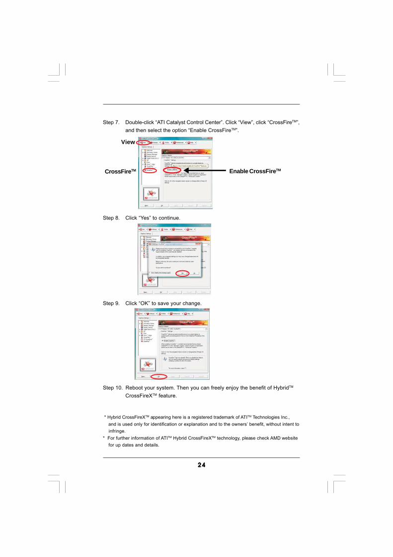
Step 7. Double-click “ATI Catalyst Control Center”. Click “View”, click “CrossFireTM”,and then select the option “Enable CrossFireTM”.
View
CrossFireTM Enable CrossFireTM
Step 8. Click “Yes” to continue.
Step 9. Click “OK” to save your change.
Step 10. Reboot your system. Then you can freely enjoy the benefit of HybridTM
CrossFireXTM feature.

2525252525
2.72.72.72.72.7 ASRock Smart Remote Installation GuideASRock Smart Remote Installation GuideASRock Smart Remote Installation GuideASRock Smart Remote Installation GuideASRock Smart Remote Installation GuideASRock Smart Remote is only used for ASRock motherboard with CIR header.Please refer to below procedures for the quick installation and usage of ASRockSmart Remote.
Step1. Find the CIR header located next tothe USB 2.0 header on ASRockmotherboard.
Step2. Connect the front USB cable to theUSB 2.0 header (as below, pin 1-5)and the CIR header. Pleasemake sure the wire assignments andthe pin assignments are matchedcorrectly.
Step3. Install Multi-Angle CIR Receiver tothe front USB port. If Multi-Angle CIRReceiver cannot successfully receivethe infrared signals from MCERemote Controller, please try toinstall it to the other front USB port.
1 2 43 5
USB 2.0 header (9-pin, blue)
CIR header (4-pin, white)
3 CIR sensors in different angles
1. Only one of the front USB port can support CIR function. Whenthe CIR function is enabled, the other port will remain USBfunction.
2. Multi-Angle CIR Receiver is used for front USB only. Please donot use the rear USB bracket to connect it on the rear panel.Multi-Angle CIR Receiver can receive the multi-direction infraredsignals (top, down and front), which is compatible with most ofthe chassis on the market.
3. The Multi-Angle CIR Receiver does not support Hot-Plugfunction. Please install it before you boot the system.
* ASRock Smart Remote is only supported by some of ASRock motherboards. Please refer to ASRock website for the motherboard support list: http://www.asrock.com
USB_PWRP-
P+GND
DUMMY
ATX+5VSBIRRX
IRTX GND
2626262626
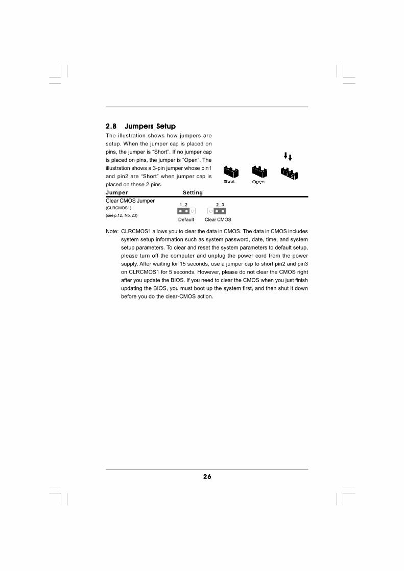
2.82.82.82.82.8 Jumpers SetupJumpers SetupJumpers SetupJumpers SetupJumpers SetupThe illustration shows how jumpers aresetup. When the jumper cap is placed onpins, the jumper is “Short”. If no jumper capis placed on pins, the jumper is “Open”. Theillustration shows a 3-pin jumper whose pin1and pin2 are “Short” when jumper cap isplaced on these 2 pins.Jumper SettingClear CMOS Jumper(CLRCMOS1)
(see p.12, No. 23)
Note: CLRCMOS1 allows you to clear the data in CMOS. The data in CMOS includessystem setup information such as system password, date, time, and systemsetup parameters. To clear and reset the system parameters to default setup,please turn off the computer and unplug the power cord from the powersupply. After waiting for 15 seconds, use a jumper cap to short pin2 and pin3on CLRCMOS1 for 5 seconds. However, please do not clear the CMOS rightafter you update the BIOS. If you need to clear the CMOS when you just finishupdating the BIOS, you must boot up the system first, and then shut it downbefore you do the clear-CMOS action.
Clear CMOS
2_31_2
Default
2727272727
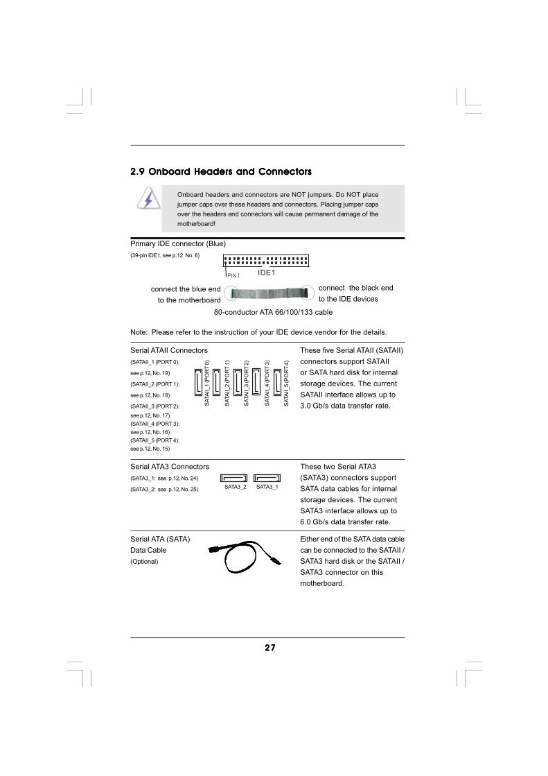
Serial ATAII Connectors These five Serial ATAII (SATAII)(SATAII_1 (PORT 0): connectors support SATAIIsee p.12, No. 19) or SATA hard disk for internal(SATAII_2 (PORT 1): storage devices. The currentsee p.12, No. 18) SATAII interface allows up to(SATAII_3 (PORT 2): 3.0 Gb/s data transfer rate.see p.12, No. 17)(SATAII_4 (PORT 3):see p.12, No. 16)(SATAII_5 (PORT 4):see p.12, No. 15)
Serial ATA (SATA) Either end of the SATA data cableData Cable can be connected to the SATAII /(Optional) SATA3 hard disk or the SATAII /
SATA3 connector on thismotherboard.
2.9 Onboard Headers and Connectors2.9 Onboard Headers and Connectors2.9 Onboard Headers and Connectors2.9 Onboard Headers and Connectors2.9 Onboard Headers and Connectors
Onboard headers and connectors are NOT jumpers. Do NOT placejumper caps over these headers and connectors. Placing jumper capsover the headers and connectors will cause permanent damage of themotherboard!
Primary IDE connector (Blue)(39-pin IDE1, see p.12 No. 8)
Note: Please refer to the instruction of your IDE device vendor for the details.
connect the black endto the IDE devices
connect the blue endto the motherboard
IDE1PIN1
80-conductor ATA 66/100/133 cable
SATA
II_1
(PO
RT
0)
SATA
II_2
(PO
RT
1)
SATA
II_3
(PO
RT
2)
SATA
II_4
(PO
RT
3)
SATA
II_5
(PO
RT
4)
Serial ATA3 Connectors These two Serial ATA3(SATA3_1: see p.12, No. 24) (SATA3) connectors support(SATA3_2: see p.12, No. 25) SATA data cables for internal
storage devices. The currentSATA3 interface allows up to6.0 Gb/s data transfer rate.
SATA3_2 SATA3_1

2828282828
USB 2.0 Headers Besides four default USB 2.0(9-pin USB10_11) ports on the I/O panel, there are(see p.12 No. 22) three USB 2.0 headers on this
motherboard. Each USB 2.0header can support two USB2.0 ports.
(9-pin USB8_9)(see p.12 No. 12)
(9-pin USB6_7)(see p.12 No. 11)
1
USB_PWRP-10
GND
DUMMY
USB_PWR
P+10
GND
P-11P+11
1
USB_PWRP-8
GND
DUMMY
USB_PWR
P+8
GND
P-9P+9
USB_PWR
USB_PWR
P+7P-7
P+6P-6
GND
GND
DUMMY
1
Consumer Infrared Module Header This header can be used to(4-pin CIR1) connect the remote(see p.12 No. 9) controller receiver.
Infrared Module Header This header supports an(5-pin IR1) optional wireless transmitting(see p.12 No. 26) and receiving infrared module.
DUMMY
GND
+5VIRTX
IRRX
1
1
ATX+5VSB
IRTXGND
IRRX
J_SENSE
OUT2_L
1
MIC_RETPRESENCE#
GND
OUT2_RMIC2_R
MIC2_L
OUT_RET
Front Panel Audio Header This is an interface for the front(9-pin HD_AUDIO1) panel audio cable that allows(see p.12, No. 32) convenient connection and
control of audio devices.
Internal Audio Connectors This connector allows you(4-pin CD1) to receive stereo audio input(CD1: see p.12 No. 33) from sound sources such as
a CD-ROM, DVD-ROM, TVtuner card, or MPEG card.
CD-L
GNDGND
CD-R
CD1

2929292929
Chassis and Power Fan Connectors Please connect the fan cables(4-pin CHA_FAN1) to the fan connectors and(see p.12 No. 10) match the black wire to the
(3-pin PWR_FAN1)(see p.12 No. 31)
GND
+12V
PWR_FAN_SPEED
CPU Fan Connector Please connect the CPU fan(4-pin CPU_FAN1) cable to this connector and(see p.12 No. 1) match the black wire to the
ground pin.
Though this motherboard provides 4-Pin CPU fan (Quiet Fan) support, the 3-Pin CPU fan still can work successfully even without the fan speed control function. If you plan to connect the 3-Pin CPU fan to the CPU fan connector on this motherboard, please connect it to Pin 1-3.
3-Pin Fan Installation
Pin 1-3 Connected
FAN_SPEED_CONTROL
GND
+12V
CHA_FAN_SPEED
+5V
DUMMYDUMMY
SPEAKER
1Chassis Speaker Header Please connect the chassis(4-pin SPEAKER 1) speaker to this header.(see p.12 No. 21)
GND
PWRBTN#PLED-
PLED+
DUMMYRESET#
GND
HDLED+HDLED-
1
System Panel Header This header accommodates(9-pin PANEL1) several system front panel(see p.12 No. 20) functions.
1. High Definition Audio supports Jack Sensing, but the panel wire on the chassis must support HDA to function correctly. Please follow the
instruction in our manual and chassis manual to install your system.2. If you use AC’97 audio panel, please install it to the front panel audio header as below: A. Connect Mic_IN (MIC) to MIC2_L. B. Connect Audio_R (RIN) to OUT2_R and Audio_L (LIN) to OUT2_L.
C. Connect Ground (GND) to Ground (GND). D. MIC_RET and OUT_RET are for HD audio panel only. You don’t need to connect them for AC’97 audio panel.
E. To activate the front mic. For Windows® XP / XP 64-bit OS: Select “Mixer”. Select “Recorder”. Then click “FrontMic”. For Windows® 7 / 7 64-bit / VistaTM / VistaTM 64-bit OS: Go to the "FrontMic" Tab in the Realtek Control panel. Adjust “Recording Volume”.
4321
3 03 03 03 03 0
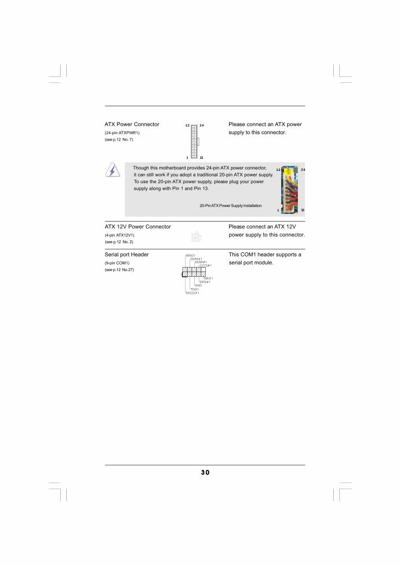
ATX Power Connector Please connect an ATX power(24-pin ATXPWR1) supply to this connector.(see p.12 No. 7)
12
1
24
13
20-Pin ATX Power Supply Installation
Though this motherboard provides 24-pin ATX power connector, it can still work if you adopt a traditional 20-pin ATX power supply. To use the 20-pin ATX power supply, please plug your power supply along with Pin 1 and Pin 13.
12
1
24
13
ATX 12V Power Connector Please connect an ATX 12V(4-pin ATX12V1) power supply to this connector.(see p.12 No. 2)
Serial port Header This COM1 header supports a(9-pin COM1) serial port module.(see p.12 No.27)
CCTS#1DDSR#1
DDTR#1RRXD1
DDCD#1TTXD1
GNDRRTS#1
RRI#1
1
3131313131
2.11 Hot Plug F2.11 Hot Plug F2.11 Hot Plug F2.11 Hot Plug F2.11 Hot Plug Function for SAunction for SAunction for SAunction for SAunction for SATTTTTAII / SAAII / SAAII / SAAII / SAAII / SATTTTTA3 HDDsA3 HDDsA3 HDDsA3 HDDsA3 HDDsThis motherboard supports Hot Plug function for SATAII / SATA3 in RAID / AHCI mode.AMD SB710 / ASMedia ASM1061 chipset provides hardware support for AdvancedHost controller Interface (AHCI), a new programming interface for SATA host controllersdeveloped thru a joint industry effort.
NOTEWhat is Hot Plug Function?If the SATAII / SATA3 HDDs are NOT set for RAID configuration, it iscalled “Hot Plug” for the action to insert and remove the SATAII / SATA3HDDs while the system is still power-on and in working condition.However, please note that it cannot perform Hot Plug if the OS has beeninstalled into the SATAII / SATA3 HDD.
2.102.102.102.102.10 Serial ASerial ASerial ASerial ASerial ATTTTTAII (SAAII (SAAII (SAAII (SAAII (SATTTTTAII) / Serial AAII) / Serial AAII) / Serial AAII) / Serial AAII) / Serial ATTTTTA3 (SAA3 (SAA3 (SAA3 (SAA3 (SATTTTTA3) Hard DisksA3) Hard DisksA3) Hard DisksA3) Hard DisksA3) Hard Disks
InstallationInstallationInstallationInstallationInstallationThis motherboard adopts AMD SB710 chipset that supports Serial ATAII (SATAII)hard disks. This motherboard also adopts ASMedia ASM1061 chipset thatsupports Serial ATA3 (SATA3) hard disks. You may install SATAII / SATA3 harddisks on this motherboard for internal storage devices. This section will guide youto install the SATAII / SATA3 hard disks.
STEP 1: Install the SATAII / SATA3 hard disks into the drive bays of your chassis.STEP 2: Connect the SATA power cable to the SATAII / SATA3 hard disk.STEP 3: Connect one end of the SATA data cable to the motherboard’s SATAII /
SATA3 connector.STEP 4: Connect the other end of the SATA data cable to the SATAII / SATA3 hard
disk.

3232323232
Caution1. Without SATA 15-pin power connector interface, the SATA / SATAII / SATA3 Hot Plug cannot be processed.2. Even some SATA / SATAII / SATA3 HDDs provide both SATA 15-pin power connector and IDE 1x4-pin conventional power connector interfaces, the IDE 1x4-pin conventional power connector interface is definitely not able to support Hot Plug and will cause the HDD damage and data loss.
SATA 7-pinconnector
1x4-pin conventionalpower connector (White)connect to power supply
A. SATA data cable (Red) B. SATA power cable
2.12 SA2.12 SA2.12 SA2.12 SA2.12 SATTTTTA / SAA / SAA / SAA / SAA / SATTTTTAII / SAAII / SAAII / SAAII / SAAII / SATTTTTA3 HDD Hot Plug FA3 HDD Hot Plug FA3 HDD Hot Plug FA3 HDD Hot Plug FA3 HDD Hot Plug Feature andeature andeature andeature andeature and
Operation GuideOperation GuideOperation GuideOperation GuideOperation GuideThis motherboard supports Hot Plug feature for SATA / SATAII / SATA3 HDD in RAID/ AHCI mode. Please read below operation guide of Hot Plug feature carefully. Beforeyou process the SATA / SATAII / SATA3 HDD Hot Plug, please check below cableaccessories from the motherboard gift box pack.A. 7-pin SATA data cableB. SATA power cable with SATA 15-pin power connector interface
The SATA 15-pin powerconnector (Black) connectto SATA / SATAII / SATA3 HDD
Points of attention, before you process the Hot Plug:1. Below operation procedure is designed only for our motherboard, which supports SATA / SATAII / SATA3 HDD Hot Plug. * The SATA / SATAII / SATA3 Hot Plug feature might not be supported by the chipset because of its limitation, the SATA / SATAII / SATA3 Hot Plug support information of our motherboard is indicated in the product spec on our website: www.asrock.com2. Make sure your SATA / SATAII / SATA3 HDD can support Hot Plug function from your dealer or HDD user manual. The SATA / SATAII / SATA3 HDD, which cannot support Hot Plug function, will be damaged under the Hot Plug operation.3. Please make sure the SATA / SATAII / SATA3 driver is installed into system properly. The latest SATA / SATAII / SATA3 driver is available on our support website: www.asrock.com4. Make sure to use the SATA power cable & data cable, which are from our motherboard package.5. Please follow below instructions step by step to reduce the risk of HDD crash or data loss.
3333333333
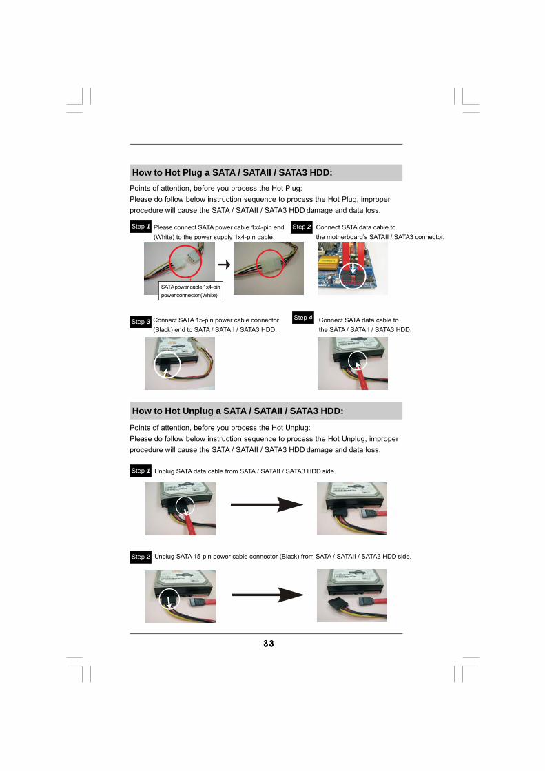
How to Hot Plug a SATA / SATAII / SATA3 HDD:Points of attention, before you process the Hot Plug:Please do follow below instruction sequence to process the Hot Plug, improperprocedure will cause the SATA / SATAII / SATA3 HDD damage and data loss.
Connect SATA data cable tothe motherboard’s SATAII / SATA3 connector.
Connect SATA 15-pin power cable connector(Black) end to SATA / SATAII / SATA3 HDD.
Connect SATA data cable tothe SATA / SATAII / SATA3 HDD.
How to Hot Unplug a SATA / SATAII / SATA3 HDD:
Points of attention, before you process the Hot Unplug:Please do follow below instruction sequence to process the Hot Unplug, improperprocedure will cause the SATA / SATAII / SATA3 HDD damage and data loss.
Please connect SATA power cable 1x4-pin end(White) to the power supply 1x4-pin cable.
Step 1 Step 2
Step 3 Step 4
Step 2
SATA power cable 1x4-pinpower connector (White)
Unplug SATA data cable from SATA / SATAII / SATA3 HDD side.
Unplug SATA 15-pin power cable connector (Black) from SATA / SATAII / SATA3 HDD side.
Step 1

3434343434
2.132.132.132.132.13 Driver Installation GuideDriver Installation GuideDriver Installation GuideDriver Installation GuideDriver Installation GuideTo install the drivers to your system, please insert the support CD to your opticaldrive first. Then, the drivers compatible to your system can be auto-detected andlisted on the support CD driver page. Please follow the order from up to bottomside to install those required drivers. Therefore, the drivers you install can workproperly.
2.142.142.142.142.14 Installing WindowsInstalling WindowsInstalling WindowsInstalling WindowsInstalling Windows®®®®® 7 / 7 64-bit / Vista 7 / 7 64-bit / Vista 7 / 7 64-bit / Vista 7 / 7 64-bit / Vista 7 / 7 64-bit / VistaTMTMTMTMTM / Vista / Vista / Vista / Vista / VistaTMTMTMTMTM
64-bit W64-bit W64-bit W64-bit W64-bit With RAID Fith RAID Fith RAID Fith RAID Fith RAID FunctionsunctionsunctionsunctionsunctionsIf you want to install Windows® 7 / 7 64-bit / VistaTM / VistaTM 64-bit on a RAID diskcomposed of 2 or more SATA / SATAII HDDs with RAID functions, please follow belowsteps.
STEP 1: Set up UEFI.A. Enter UEFI SETUP UTILITY Advanced screen Storage
Configuration.B. Set the “SATA Mode” option to [RAID].STEP 2: Use “RAID Installation Guide” to set RAID configuration.Before you start to configure RAID function, you need to check the RAID installationguide in the Support CD for proper configuration. Please refer to the BIOS RAIDinstallation guide part of the document in the following path in the Support CD:.. \ RAID Installation GuideSTEP 3: Install Windows® 7 / 7 64-bit / VistaTM / VistaTM 64-bit OS on your system.
RAID mode is not supported under Windows® XP / XP 64-bit.
NOTE1. If you install Windows® 7 / 7 64-bit / VistaTM / VistaTM 64-bit on IDE HDDs and want to manage (create, convert, delete, or rebuild) RAID functions on SATA / SATAII HDDs, you still need to set up “SATA Mode” to [RAID] in UEFI first. Then, please set the RAID configuration by using the Windows RAID installation guide in the following path in the Support CD: .. \ RAID Installation Guide
NOTE2. Currently, if you install Windows® 7 / 7 64-bit / VistaTM / VistaTM 64-bit on IDE HDDs and there are no SATA / SATAII device used, please set up “SATA Mode” to [IDE] in UEFI.
3535353535
2.152.152.152.152.15 Installing WindowsInstalling WindowsInstalling WindowsInstalling WindowsInstalling Windows®®®®® 7 / 7 64-bit / Vista 7 / 7 64-bit / Vista 7 / 7 64-bit / Vista 7 / 7 64-bit / Vista 7 / 7 64-bit / VistaTMTMTMTMTM / / / / /
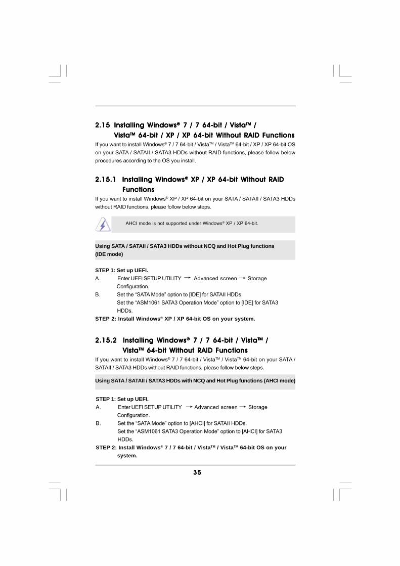
VistaVistaVistaVistaVistaTMTMTMTMTM 64-bit / XP / XP 64-bit Without RAID Functions 64-bit / XP / XP 64-bit Without RAID Functions 64-bit / XP / XP 64-bit Without RAID Functions 64-bit / XP / XP 64-bit Without RAID Functions 64-bit / XP / XP 64-bit Without RAID FunctionsIf you want to install Windows® 7 / 7 64-bit / VistaTM / VistaTM 64-bit / XP / XP 64-bit OSon your SATA / SATAII / SATA3 HDDs without RAID functions, please follow belowprocedures according to the OS you install.
2.15.1 Installing Windows2.15.1 Installing Windows2.15.1 Installing Windows2.15.1 Installing Windows2.15.1 Installing Windows®®®®® XP / XP 64-bit Without RAID XP / XP 64-bit Without RAID XP / XP 64-bit Without RAID XP / XP 64-bit Without RAID XP / XP 64-bit Without RAID
Functions Functions Functions Functions FunctionsIf you want to install Windows® XP / XP 64-bit on your SATA / SATAII / SATA3 HDDswithout RAID functions, please follow below steps.
AHCI mode is not supported under Windows® XP / XP 64-bit.
Using SATA / SATAII / SATA3 HDDs without NCQ and Hot Plug functions(IDE mode)
STEP 1: Set up UEFI.A. Enter UEFI SETUP UTILITY Advanced screen Storage
Configuration.B. Set the “SATA Mode” option to [IDE] for SATAII HDDs.
Set the “ASM1061 SATA3 Operation Mode” option to [IDE] for SATA3 HDDs.
STEP 2: Install Windows® XP / XP 64-bit OS on your system.
2.15.2 Installing Windows2.15.2 Installing Windows2.15.2 Installing Windows2.15.2 Installing Windows2.15.2 Installing Windows®®®®® 7 / 7 64-bit / Vista 7 / 7 64-bit / Vista 7 / 7 64-bit / Vista 7 / 7 64-bit / Vista 7 / 7 64-bit / VistaTMTMTMTMTM / / / / /
Vista Vista Vista Vista VistaTMTMTMTMTM 64-bit Without RAID Functions 64-bit Without RAID Functions 64-bit Without RAID Functions 64-bit Without RAID Functions 64-bit Without RAID FunctionsIf you want to install Windows® 7 / 7 64-bit / VistaTM / VistaTM 64-bit on your SATA /SATAII / SATA3 HDDs without RAID functions, please follow below steps.
Using SATA / SATAII / SATA3 HDDs with NCQ and Hot Plug functions (AHCI mode)
STEP 1: Set up UEFI.A. Enter UEFI SETUP UTILITY Advanced screen Storage
Configuration.B. Set the “SATA Mode” option to [AHCI] for SATAII HDDs.
Set the “ASM1061 SATA3 Operation Mode” option to [AHCI] for SATA3 HDDs.
STEP 2: Install Windows® 7 / 7 64-bit / VistaTM / VistaTM 64-bit OS on your system.

3636363636
2.162.162.162.162.16 Untied Overclocking TUntied Overclocking TUntied Overclocking TUntied Overclocking TUntied Overclocking TechnologyechnologyechnologyechnologyechnologyThis motherboard supports Untied Overclocking Technology, which means duringoverclocking, FSB enjoys better margin due to fixed PCI / PCIE buses. Before youenable Untied Overclocking function, please enter “Overclock Mode” option of UEFIsetup to set the selection from [Auto] to [Manual]. Therefore, CPU FSB is untiedduring overclocking, but PCI / PCIE buses are in the fixed mode so that FSB canoperate under a more stable overclocking environment.
Please refer to the warning on page 8 for the possible overclocking riskbefore you apply Untied Overclocking Technology.
STEP 1: Set up UEFI.A. Enter UEFI SETUP UTILITY Advanced screen Storage
Configuration.B. Set the “SATA Mode” option to [IDE] for SATAII HDDs.
Set the “ASM1061 SATA3 Operation Mode” option to [IDE] for SATA3 HDDs.
STEP 2: Install Windows® 7 / 7 64-bit / VistaTM / VistaTM 64-bit OS on yoursystem.
Using SATA / SATAII / SATA3 HDDs without NCQ and Hot Plug functions(IDE mode)
3737373737
3.3.3.3.3. UEFI SETUP UTILITYUEFI SETUP UTILITYUEFI SETUP UTILITYUEFI SETUP UTILITYUEFI SETUP UTILITY3.1 Introduction3.1 Introduction3.1 Introduction3.1 Introduction3.1 IntroductionThis section explains how to use the UEFI SETUP UTILITY to configure your system.The SPI Memory on the motherboard stores the UEFI SETUP UTILITY. You may run theUEFI SETUP UTILITY when you start up the computer. Please press <F2> or <Del>during the Power-On-Self-Test (POST) to enter the UEFI SETUP UTILITY, otherwise,POST will continue with its test routines.If you wish to enter the UEFI SETUP UTILITY after POST, restart the system bypressing <Ctl> + <Alt> + <Delete>, or by pressing the reset button on the systemchassis. You may also restart by turning the system off and then back on.
Because the UEFI software is constantly being updated, the followingUEFI setup screens and descriptions are for reference purpose only,and they may not exactly match what you see on your screen.
3.1.13.1.13.1.13.1.13.1.1 UEFI Menu BarUEFI Menu BarUEFI Menu BarUEFI Menu BarUEFI Menu BarThe top of the screen has a menu bar with the following selections:Main To set up the system time/date informationOC Tweaker To set up overclocking featuresAdvanced To set up the advanced UEFI featuresH/W Monitor To display current hardware statusBoot To set up the default system device to locate and load the
Operating SystemSecurity To set up the security featuresExit To exit the current screen or the UEFI SETUP UTILITYUse < > key or < > key to choose among the selections on the menu bar,and then press <Enter> to get into the sub screen.
3838383838
3.1.23.1.23.1.23.1.23.1.2 Navigation KeysNavigation KeysNavigation KeysNavigation KeysNavigation KeysPlease check the following table for the function description of each navigationkey.
Navigation Key(s) Function Description / Moves cursor left or right to select Screens / Moves cursor up or down to select items + / - To change option for the selected items<Enter> To bring up the selected screen<F1> To display the General Help Screen<F9> To load optimal default values for all the settings<F10> To save changes and exit the UEFI SETUP UTILITY<ESC> To jump to the Exit Screen or exit the current screen
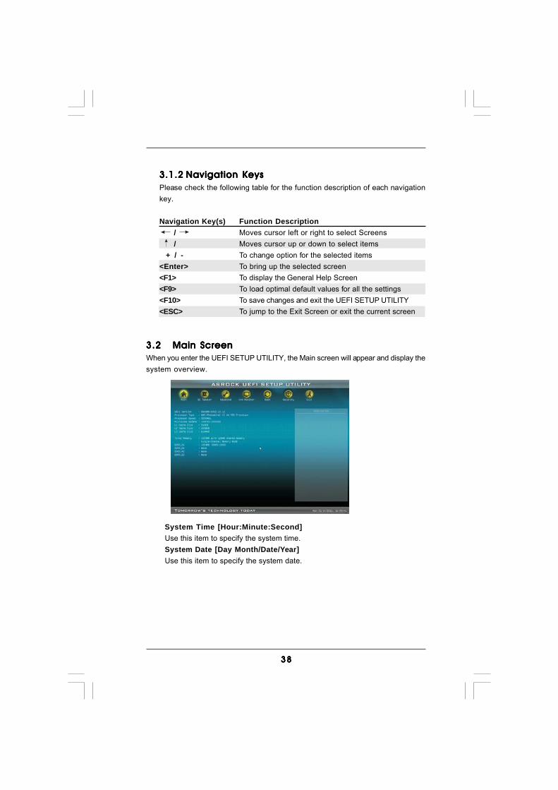
3.23.23.23.23.2 Main ScreenMain ScreenMain ScreenMain ScreenMain ScreenWhen you enter the UEFI SETUP UTILITY, the Main screen will appear and display thesystem overview.
System Time [Hour:Minute:Second]Use this item to specify the system time.System Date [Day Month/Date/Year]Use this item to specify the system date.
3939393939
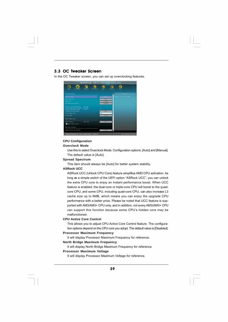
3.33.33.33.33.3 OC TOC TOC TOC TOC Tweakweakweakweakweaker Screener Screener Screener Screener ScreenIn the OC Tweaker screen, you can set up overclocking features.
CPU ConfigurationOverclock Mode
Use this to select Overclock Mode. Configuration options: [Auto] and [Manual].The default value is [Auto].
Spread SpectrumThis item should always be [Auto] for better system stability.
ASRock UCCASRock UCC (Unlock CPU Core) feature simplifies AMD CPU activation. Aslong as a simple switch of the UEFI option “ASRock UCC”, you can unlockthe extra CPU core to enjoy an instant performance boost. When UCCfeature is enabled, the dual-core or triple-core CPU will boost to the quad-core CPU, and some CPU, including quad-core CPU, can also increase L3cache size up to 6MB, which means you can enjoy the upgrade CPUperformance with a better price. Please be noted that UCC feature is sup-ported with AM3/AM3+ CPU only, and in addition, not every AM3/AM3+ CPUcan support this function because some CPU’s hidden core may bemalfunctioned.
CPU Active Core ControlThis allows you to adjust CPU Active Core Control feature. The configura-tion options depend on the CPU core you adopt. The default value is [Disabled].
Processor Maximum FrequencyIt will display Processor Maximum Frequency for reference.
North Bridge Maximum FrequencyIt will display North Bridge Maximum Frequency for reference.
Processor Maximum VoltageIt will display Processor Maximum Voltage for reference.
4040404040
Multiplier/Voltage ChangeThis item is set to [Auto] by default. If it is set to [Manual], you may adjust thevalue of Processor Frequency and Processor Voltage. However, it isrecommended to keep the default value for system stability.
CPU Frequency (MHz) Use this option to adjust CPU frequency.CPU Voltage
It allows you to adjust the value of CPU voltage. However, for safety andsystem stability, it is not recommended to adjust the value of this item.
NB Frequency (MHz) Use this option to adjust NB frequency.NB Voltage
It allows you to adjust the value of NB voltage. However, for safety andsystem stability, it is not recommended to adjust the value of this item.
HT Bus Speed (MHz)This feature allows you selecting Hyper-Transport bus speed. Configura-tion options: [Auto], [200MHz] to [2000MHz].
HT Bus WidthThis feature allows you selecting Hyper-Transport bus width. Configura-tion options: [Auto], [8 Bit] and [16 Bit].
DRAM ConfigurationDRAM Frequency
If [Auto] is selected, the motherboard will detect the memory module(s)inserted and assigns appropriate frequency automatically.

4141414141
Power Down EnableUse this item to enable or disable DDR power down mode.
Bank InterleavingInterleaving allows memory accesses to be spread out over banks on thesame node, or accross nodes, decreasing access contention.
Channel InterleavingIt allows you to enable Channel Memory Interleaving. Configuration options:[Disabled], [Address bits 6], [Address bits 12], [HASH 1] and [HASH 2]. Thedefault value is [HASH 2].
CAS# Latency (tCL)Use this item to change CAS# Latency (tCL) Auto/Manual setting. Thedefault is [Auto].
RAS# to CAS# Delay (tRCD)Use this item to change RAS# to CAS# Delay (tRCD) Auto/Manual setting.The default is [Auto].
Row Precharge Time (tRP)Use this item to change Row Precharge Time (tRP) Auto/Manual setting.The default is [Auto].
RAS# Active Time (tRAS)Use this item to change RAS# Active Time (tRAS) Auto/Manual setting.The default is [Auto].
Command Rate (CR)Use this item to change Command Rate (CR) Auto/Manual setting. Min:1N. Max: 2N. The default is [Auto].
RAS# Cycle Time (tRC)Use this item to change RAS# Cycle Time (tRC) Auto/Manual setting.The default is [Auto].
DRAM Timing Control
4242424242
Write Recovery Time (tWR)Use this item to change Write Recovery Time (tWR) Auto/Manual setting.The default is [Auto].
Refresh Cyle Time (tRFC)Use this item to change Refresh Cyle Time (tRFC) Auto/Manual setting.The default is [Auto].
RAS to RAS Delay (tRRD)Use this item to change RAS to RAS Delay (tRRD) Auto/Manual setting.The default is [Auto].
Write to Read Delay (tWTR)Use this item to change Write to Read Delay (tWTR) Auto/Manual setting.The default is [Auto].
Read to Precharge (tRTP)Use this item to change Read to Precharge (tRTP) Auto/Manual setting.The default is [Auto].
Four Activate Window (tFAW)Use this item to change Four Activate Window (tFAW) Auto/Manual setting.The default is [Auto].
GPU Clock OverrideOnboard GPU Clock Override
Use this item to enable ot disable GPU clock override. The default value is[Disabled].
Voltage ControlCPU Load-Line Calibration
CPU Load-Line Calibration helps prevent CPU voltage droop when thesystem is under heavy load.
DRAM VoltageUse this to select DRAM Voltage. The default value is [Auto].
NB Core VoltageUse this to select NB Core Voltage. The default value is [Auto].
Would you like to save current setting user defaults?In this option, you are allowed to load and save three user defaultsaccording to your own requirements.
4343434343
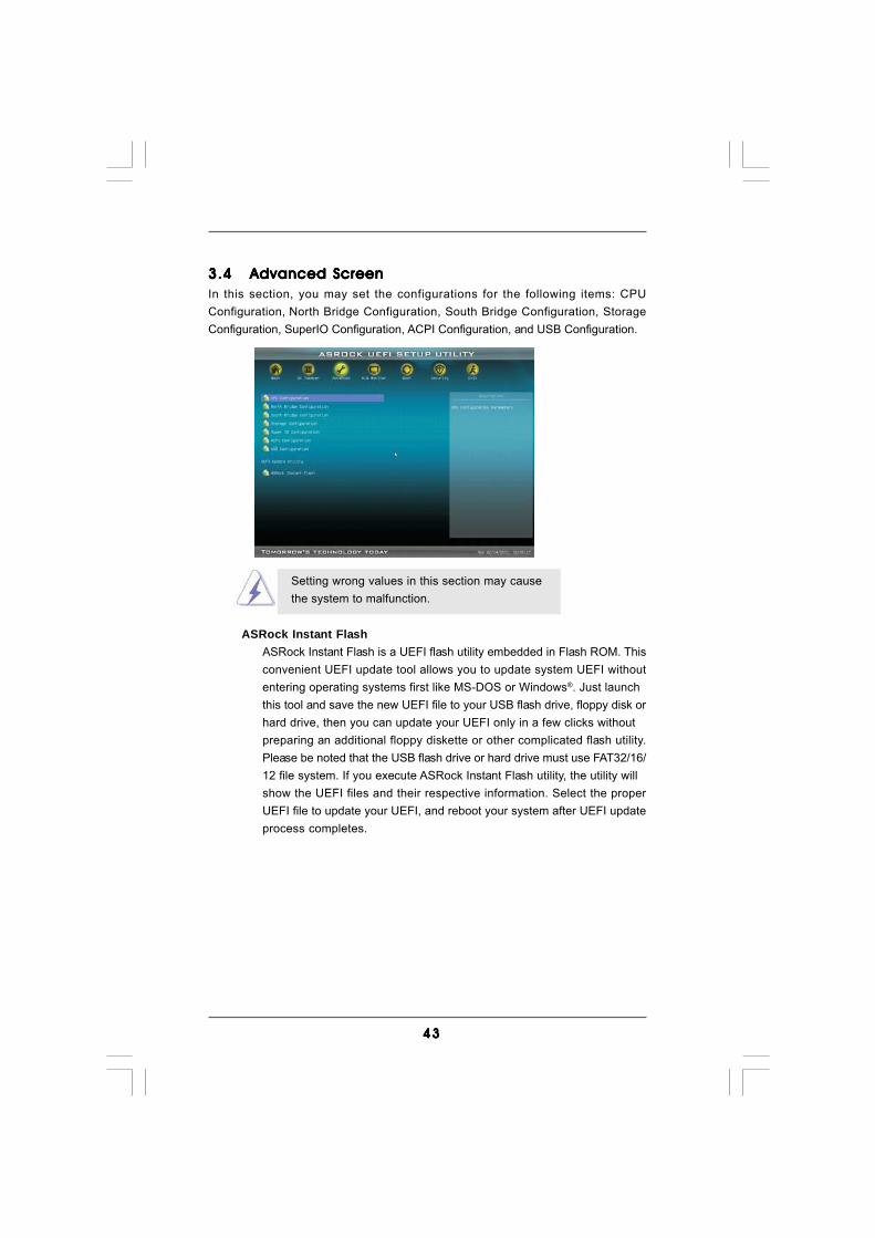
3.43.43.43.43.4 Advanced ScreenAdvanced ScreenAdvanced ScreenAdvanced ScreenAdvanced ScreenIn this section, you may set the configurations for the following items: CPUConfiguration, North Bridge Configuration, South Bridge Configuration, StorageConfiguration, SuperIO Configuration, ACPI Configuration, and USB Configuration.
Setting wrong values in this section may causethe system to malfunction.
ASRock Instant FlashASRock Instant Flash is a UEFI flash utility embedded in Flash ROM. Thisconvenient UEFI update tool allows you to update system UEFI withoutentering operating systems first like MS-DOS or Windows®. Just launchthis tool and save the new UEFI file to your USB flash drive, floppy disk orhard drive, then you can update your UEFI only in a few clicks withoutpreparing an additional floppy diskette or other complicated flash utility.Please be noted that the USB flash drive or hard drive must use FAT32/16/12 file system. If you execute ASRock Instant Flash utility, the utility willshow the UEFI files and their respective information. Select the properUEFI file to update your UEFI, and reboot your system after UEFI updateprocess completes.

4444444444
Cool ‘n’ QuietUse this item to enable or disable AMD’s Cool ‘n’ QuietTM technology. Thedefault value is [Enabled]. Configuration options: [Auto], [Enabled] and[Disabled]. If you install Windows® 7 / VistaTM and want to enable thisfunction, please set this item to [Enabled]. Please note that enabling thisfunction may reduce CPU voltage and memory frequency, and lead tosystem stability or compatibility issue with some memory modules or powersupplies. Please set this item to [Disable] if above issue occurs.
Secure Virtual Machine When this option is set to [Enabled], a VMM (Virtual Machine Architecture)can utilize the additional hardware capabilities provided by AMD-V. Thedefault value is [Enabled]. Configuration options: [Enabled] and [Disabled].
Enhance Halt State (C1E)All processors support the Halt State (C1). The C1 state is supportedthrough the native processor instructions HLT and MWAIT and requires nohardware support from the chipset. In the C1 power state, the processormaintains the context of the system caches.
CPU Thermal ThrottleUse this item to enable CPU internal thermal control mechanism to keep theCPU from overheated. The default value is [Auto].
3.4.13.4.13.4.13.4.13.4.1 CPU ConfigurationCPU ConfigurationCPU ConfigurationCPU ConfigurationCPU Configuration

4545454545
3.4.23.4.23.4.23.4.23.4.2 North Bridge ConfigurationNorth Bridge ConfigurationNorth Bridge ConfigurationNorth Bridge ConfigurationNorth Bridge Configuration
Internal Graphics ModeThis allows you to adjust internal graphics mode. Configuration options:[UMA] and [Disabled]. The default value is [UMA].
Share MemoryThis allows you to set share memory feature. The default value is [Auto].Configuration options: [Auto], [32MB], [64MB], [128MB], [256MB] and[512MB]. This option only appears when you set “Internal Graphics Mode”to [UMA].
Onboard HDMI HD AudioThis allows you to enable or disable the onboard HDMI HD Audio in AMD880G. If you use Dual-link DVI monitor, please set this item to [Disabled].
Primary Graphics AdapterThis item will switch the PCI Bus scanning order while searching for videocard. It allows you to select the type of Primary VGA in case of multiplevideo controllers. The default value of this feature is [PCI Express]. Con-figuration options: [PCI], [Onboard] and [PCI Express].
PCIE2 Link ASPMThis allows you to adjust PCIE2 Link ASPM. Configuration options:[Disabled], [L0s], [L1] and [L0s & L1]. The default value is [Disabled].

4646464646
3.4.33.4.33.4.33.4.33.4.3 South Bridge ConfigurationSouth Bridge ConfigurationSouth Bridge ConfigurationSouth Bridge ConfigurationSouth Bridge Configuration
Onboard LANThis allows you to enable or disable the onboard LAN feature.
Onboard HD AudioSelect [Auto], [Enabled] or [Disabled] for the onboard HD Audio feature. Ifyou select [Auto], the onboard HD Audio will be disabled when PCI SoundCard is plugged.
Front PanelSelect [Auto] or [Disabled] for the onboard HD Audio Front Panel.

4747474747
3.4.43.4.43.4.43.4.43.4.4 Storage ConfigurationStorage ConfigurationStorage ConfigurationStorage ConfigurationStorage Configuration
IDE ControllerUse this item to enable or disable the “IDE Controller” feature.
SATA ControllerUse this item to enable or disable the “SATA Controller” feature.
SATA ModeThis item is for SATAII_1 (PORT 0) to SATAII_5 (PORT 4) ports only. Use thisitem to adjust SATA Mode. The default value of this option is [IDE Mode].Configuration options: [AHCI Mode], [RAID Mode] and [IDE Mode].
SATA IDE Combined ModeThis item is for SATAII_5 (PORT 4) and eSATA2 ports only. Use this item toenable or disable SATA IDE combined mode. The default value is [Enabled].
If you want to build RAID on SATAII_5 (PORT 4) and eSATA2ports, please disable this item.
If you set this item to RAID mode, it is suggested to installSATA ODD driver on SATAII_5 (PORT 4) port.
ASM1061 SATA3 Operation ModeThis item is for SATA3_1 and SATA3_2 ports only. Use this item to adjustSATA Mode. The default value of this option is [IDE Mode]. Configurationoptions: [IDE Mode], [AHCI Mode] and [Disabled].
4848484848
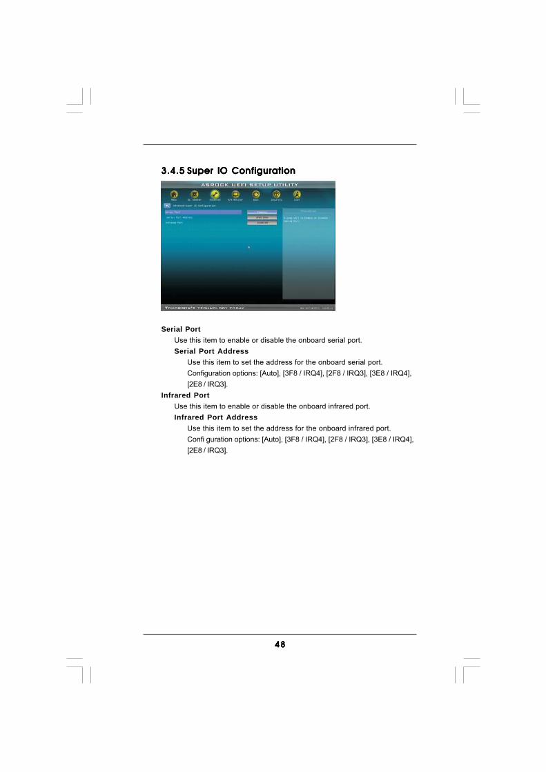
3.4.53.4.53.4.53.4.53.4.5 Super IO ConfigurationSuper IO ConfigurationSuper IO ConfigurationSuper IO ConfigurationSuper IO Configuration
Serial PortUse this item to enable or disable the onboard serial port.Serial Port Address
Use this item to set the address for the onboard serial port.Configuration options: [Auto], [3F8 / IRQ4], [2F8 / IRQ3], [3E8 / IRQ4],[2E8 / IRQ3].
Infrared PortUse this item to enable or disable the onboard infrared port.Infrared Port Address
Use this item to set the address for the onboard infrared port.Confi guration options: [Auto], [3F8 / IRQ4], [2F8 / IRQ3], [3E8 / IRQ4],[2E8 / IRQ3].

4949494949
3.4.63.4.63.4.63.4.63.4.6 ACPI ConfigurationACPI ConfigurationACPI ConfigurationACPI ConfigurationACPI Configuration
Suspend to RAMUse this item to select whether to auto-detect or disable the Suspend-to-RAM feature. Select [Auto] will enable this feature if the OS supports it.
Check Ready Bit Use this item to enable or disable the feature Check Ready Bit.
Restore on AC/Power Loss This allows you to set the power state after an unexpected AC/power loss. If [Power Off] is selected, the AC/power remains off when the power recovers. If [Power On] is selected, the AC/power resumes and the system starts to boot up when the power recovers.
PS/2 Keyboard Power OnUse this item to enable or disable PS/2 keyboard to turn on the system fromthe power-soft-off mode.
PCI Devices Power OnUse this item to enable or disable PCI devices to turn on the system from thepower-soft-off mode.
Ring-In Power OnUse this item to enable or disable Ring-In signals to turn on the system fromthe power-soft-off mode.
RTC Alarm Power OnUse this item to enable or disable RTC (Real Time Clock) to power on thesystem.
ACPI HPET TableUse this item to enable or disable ACPI HPET Table. The default value is[Disabled]. Please set this option to [Enabled] if you plan to use thismotherboard to submit Windows® VistaTM certification.
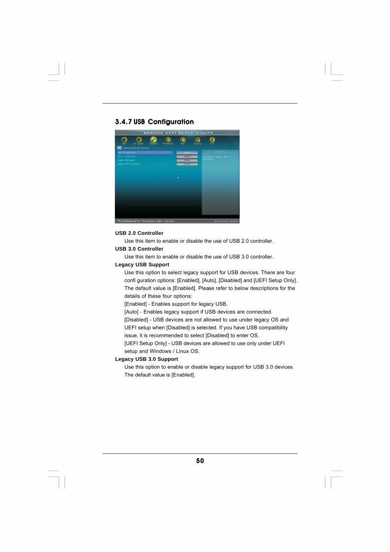
5050505050
3.4.73.4.73.4.73.4.73.4.7 USB ConfigurationUSB ConfigurationUSB ConfigurationUSB ConfigurationUSB Configuration
USB 2.0 ControllerUse this item to enable or disable the use of USB 2.0 controller.
USB 3.0 ControllerUse this item to enable or disable the use of USB 3.0 controller.
Legacy USB SupportUse this option to select legacy support for USB devices. There are fourconfi guration options: [Enabled], [Auto], [Disabled] and [UEFI Setup Only].The default value is [Enabled]. Please refer to below descriptions for thedetails of these four options:[Enabled] - Enables support for legacy USB.[Auto] - Enables legacy support if USB devices are connected.[Disabled] - USB devices are not allowed to use under legacy OS andUEFI setup when [Disabled] is selected. If you have USB compatibilityissue, it is recommended to select [Disabled] to enter OS.[UEFI Setup Only] - USB devices are allowed to use only under UEFIsetup and Windows / Linux OS.
Legacy USB 3.0 SupportUse this option to enable or disable legacy support for USB 3.0 devices.The default value is [Enabled].
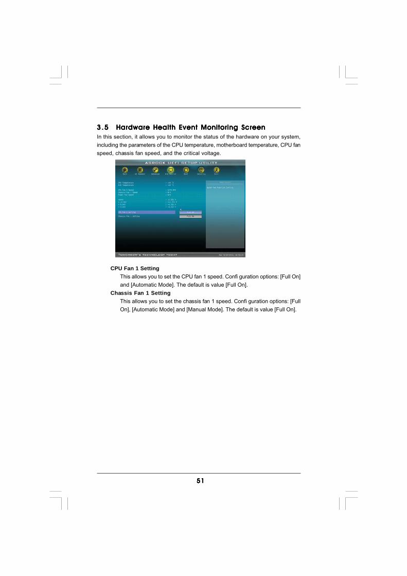
5151515151
3 .53 .53 .53 .53 .5 Hardware Health Event Monitoring ScreenHardware Health Event Monitoring ScreenHardware Health Event Monitoring ScreenHardware Health Event Monitoring ScreenHardware Health Event Monitoring ScreenIn this section, it allows you to monitor the status of the hardware on your system,including the parameters of the CPU temperature, motherboard temperature, CPU fanspeed, chassis fan speed, and the critical voltage.
CPU Fan 1 SettingThis allows you to set the CPU fan 1 speed. Confi guration options: [Full On]and [Automatic Mode]. The default is value [Full On].
Chassis Fan 1 SettingThis allows you to set the chassis fan 1 speed. Confi guration options: [FullOn], [Automatic Mode] and [Manual Mode]. The default is value [Full On].
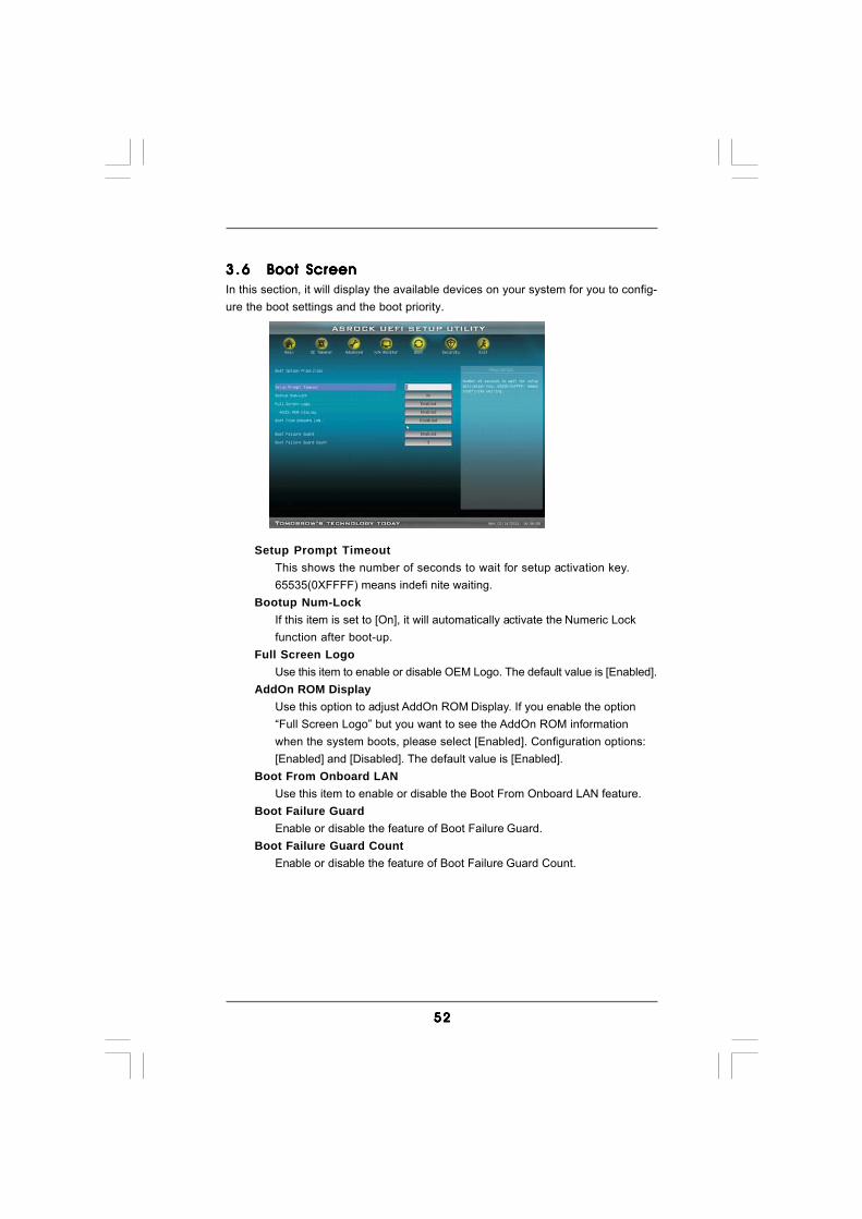
5252525252
3 .63 .63 .63 .63 .6 Boot ScreenBoot ScreenBoot ScreenBoot ScreenBoot ScreenIn this section, it will display the available devices on your system for you to config-ure the boot settings and the boot priority.
Setup Prompt TimeoutThis shows the number of seconds to wait for setup activation key.65535(0XFFFF) means indefi nite waiting.
Bootup Num-LockIf this item is set to [On], it will automatically activate the Numeric Lockfunction after boot-up.
Full Screen LogoUse this item to enable or disable OEM Logo. The default value is [Enabled].
AddOn ROM DisplayUse this option to adjust AddOn ROM Display. If you enable the option“Full Screen Logo” but you want to see the AddOn ROM informationwhen the system boots, please select [Enabled]. Configuration options:[Enabled] and [Disabled]. The default value is [Enabled].
Boot From Onboard LANUse this item to enable or disable the Boot From Onboard LAN feature.
Boot Failure GuardEnable or disable the feature of Boot Failure Guard.
Boot Failure Guard CountEnable or disable the feature of Boot Failure Guard Count.

5353535353
3.73.73.73.73.7 Security ScreenSecurity ScreenSecurity ScreenSecurity ScreenSecurity ScreenIn this section, you may set or change the supervisor/user password for the system.For the user password, you may also clear it.
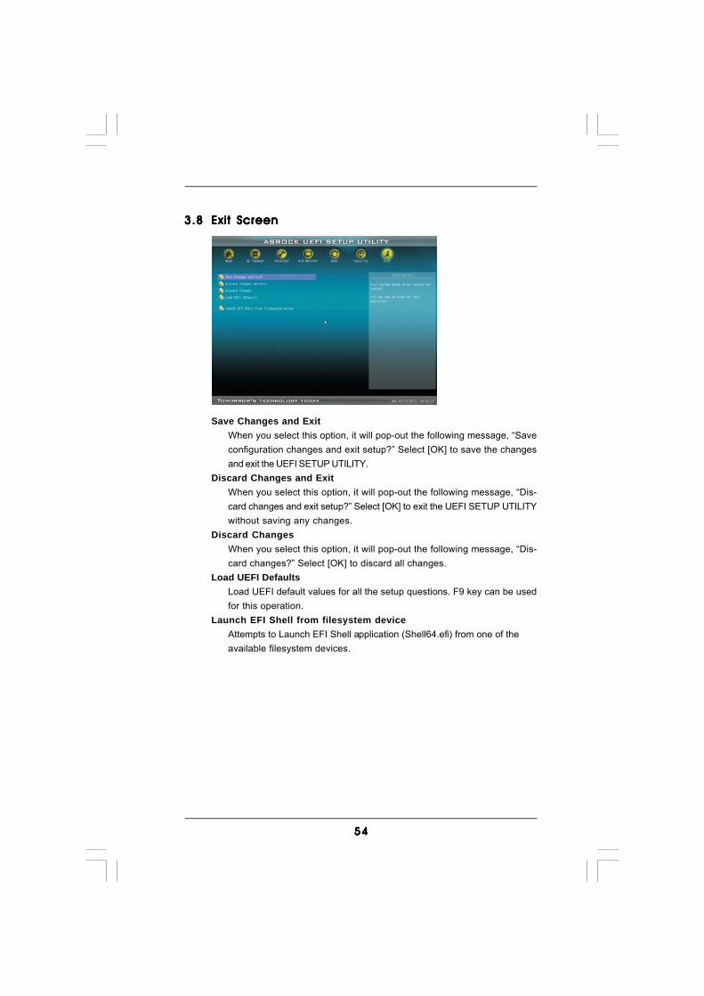
5454545454
3.83.83.83.83.8 Exit ScreenExit ScreenExit ScreenExit ScreenExit Screen
Save Changes and ExitWhen you select this option, it will pop-out the following message, “Saveconfiguration changes and exit setup?” Select [OK] to save the changesand exit the UEFI SETUP UTILITY.
Discard Changes and ExitWhen you select this option, it will pop-out the following message, “Dis-card changes and exit setup?” Select [OK] to exit the UEFI SETUP UTILITYwithout saving any changes.
Discard ChangesWhen you select this option, it will pop-out the following message, “Dis-card changes?” Select [OK] to discard all changes.
Load UEFI DefaultsLoad UEFI default values for all the setup questions. F9 key can be usedfor this operation.
Launch EFI Shell from filesystem deviceAttempts to Launch EFI Shell application (Shell64.efi) from one of theavailable filesystem devices.
5555555555
4.4.4.4.4. SofSofSofSofSof tware Supportware Supportware Supportware Supportware Supporttttt4.1 Install Operating System4.1 Install Operating System4.1 Install Operating System4.1 Install Operating System4.1 Install Operating SystemThis motherboard supports various Microsoft® Windows® operating systems: 7 / 764-bit / VistaTM / VistaTM 64-bit / XP / XP Media Center / XP 64-bit. Because motherboardsettings and hardware options vary, use the setup procedures in this chapter forgeneral reference only. Refer to your OS documentation for more information.
4.2 Support CD Information4.2 Support CD Information4.2 Support CD Information4.2 Support CD Information4.2 Support CD InformationThe Support CD that came with the motherboard contains necessary drivers anduseful utilities that enhance the motherboard features.
4.2.1 Running The Support CD4.2.1 Running The Support CD4.2.1 Running The Support CD4.2.1 Running The Support CD4.2.1 Running The Support CDTo begin using the support CD, insert the CD into your CD-ROM drive. The CDautomatically displays the Main Menu if “AUTORUN” is enabled in your computer.If the Main Menu did not appear automatically, locate and double click on the file“ASSETUP.EXE” from the BIN folder in the Support CD to display the menus.
4.2.2 Drivers Menu4.2.2 Drivers Menu4.2.2 Drivers Menu4.2.2 Drivers Menu4.2.2 Drivers MenuThe Drivers Menu shows the available devices drivers if the system detects theinstalled devices. Please install the necessary drivers to activate the devices.
4.2.3 Utilities Menu4.2.3 Utilities Menu4.2.3 Utilities Menu4.2.3 Utilities Menu4.2.3 Utilities MenuThe Utilities Menu shows the applications software that the motherboard supports.Click on a specific item then follow the installation wizard to install it.
4.2.44.2.44.2.44.2.44.2.4 Contact InformationContact InformationContact InformationContact InformationContact InformationIf you need to contact ASRock or want to know more about ASRock, welcometo visit ASRock’s website at http://www.asrock.com; or you may contact yourdealer for further information.

5656565656
Installing OS on a HDD Larger Than 2TBThis motherboard is adopting UEFI BIOS that allows Windows® OS to beinstalled on a large size HDD (>2TB). Please follow below procedure toinstall the operating system.
1. Please make sure to use Windows® VistaTM 64-bit (with SP1 or above) or Windows® 7 64-bit.2. Set AHCI Mode in UEFI Setup Utility > Advanced > Storage Configuration > SATA Mode.3. Press F11 to launch boot menu at system POST.4. Choose the item “UEFI:xxx“ to boot. (“xxx” is the device which contains your Windows® installation fi les. Normally it is an optical drive.)5. Start Windows® installation.
Related Documents