Material ID 860 352 871 Issue 1 December 2005 SYSTIMAX ® Performance Verification of GigaSPEED ® X10D Installations with Fluke N etworks DTX 1800 CableAnalyzer™

Welcome message from author
This document is posted to help you gain knowledge. Please leave a comment to let me know what you think about it! Share it to your friends and learn new things together.
Transcript
7/28/2019 860352871 Systimax Performance Verification Cableanalyzer Fluke
http://slidepdf.com/reader/full/860352871-systimax-performance-verification-cableanalyzer-fluke 1/18
Material ID 860 352 871
Issue 1December 2005
SYSTIMAX ® Performance Verification ofGigaSPEED ® X10D Installations with FlukeN etworks DTX 1800 CableAnalyzer™

7/28/2019 860352871 Systimax Performance Verification Cableanalyzer Fluke
http://slidepdf.com/reader/full/860352871-systimax-performance-verification-cableanalyzer-fluke 2/18
© 2005 CommScope, Inc. All right s reserved . Prin ted in U.S.A.
SYSTIMAX Solutions is a trademark of CommScope. All trademarks identified by ®and ™ are registeredtrademarks or trademarks, respectively, of CommScope. All other trademarks are the properties of theirrespective owners.
LinkWare™ is a trademark of the Fluke CorporationDTX 1800 CableAnalyzer™ is a trademark of the Fluke Corporation.
7/28/2019 860352871 Systimax Performance Verification Cableanalyzer Fluke
http://slidepdf.com/reader/full/860352871-systimax-performance-verification-cableanalyzer-fluke 3/18
Material ID 860 352 871Issue 1, December 2005
Overview The Fluke Networks DTX 1800 CableAnalyzer ™ instrument has been qualified by SYSTIMAX ® Labs forverification of the Guaranteed GigaSPEED ® X10D Channel Performance as well as Augmented Category6 Channel and Permanent Link testing to the proposed EIA/TIA Category 6A specifications and theproposed ISO/IEC Class E A specifications. This document describes the field testing procedures forSYSTIMAX GigaSPEED X10D installations using the Fluke Networks DTX 1800 CableAnalyzer . TheGigaSPEED X10D solution must be designed, installed, and tested by an authorized SYSTIMAXBusinessPartner in accordance with SYSTIMAX Guidelines. The GigaSPEED X10D solution componentsare listed in Table 1 below.
Table 1. GigaSPEED X10D Solut ion Components
GigaSPEED X10D 91 Series Cables
24-port UMP Panels
GigaSPEED X10D MGS500 Modular Outlets
GigaSPEED X10D GS10E Patch Cords
Note: Check SYSTIMAX X10D product information and guidelines for updates that may beavailable.
GigaSPEED X10D Guaranteed Channel PerformanceRegistered GigaSPEED X10D installations in conformance with the relevant SYSTIMAX SCS guidelinesare covered by the SYSTIMAX SCS 20 Year Assurance Program, with a GigaSPEED X10D MinimumChannel Performance Guarantee up to 500 MHz.
The GigaSPEED X10D Minimum Channel Performance Guarantee exceeds the Category 6 channelspecifications in TIA/EIA-568B.2-1 and the Class E channel specifications in the ISO/IEC 11801 2nd Ed.(2002) by significant margins, and also exceeds the proposed Category 6A specifications in the DraftAmendment 10 to TIA/EIA-568B.2 and the proposed Class E A specifications for Amendment 1.1 toISO/IEC 11801 on a swept frequency basis, as outlined in " SYSTIMAX GigaSPEED X10D Solution Channel Performance Specifications ".
All parameters comply with the governing equations given in the SYSTIMAX SCS memorandum entitled"SYSTIMAX GigaSPEED X10D Solution Channel Performance Specifications " over the entire frequencyrange.
Page 318 Pages
7/28/2019 860352871 Systimax Performance Verification Cableanalyzer Fluke
http://slidepdf.com/reader/full/860352871-systimax-performance-verification-cableanalyzer-fluke 4/18
Material ID 860 352 871Engineering Guide
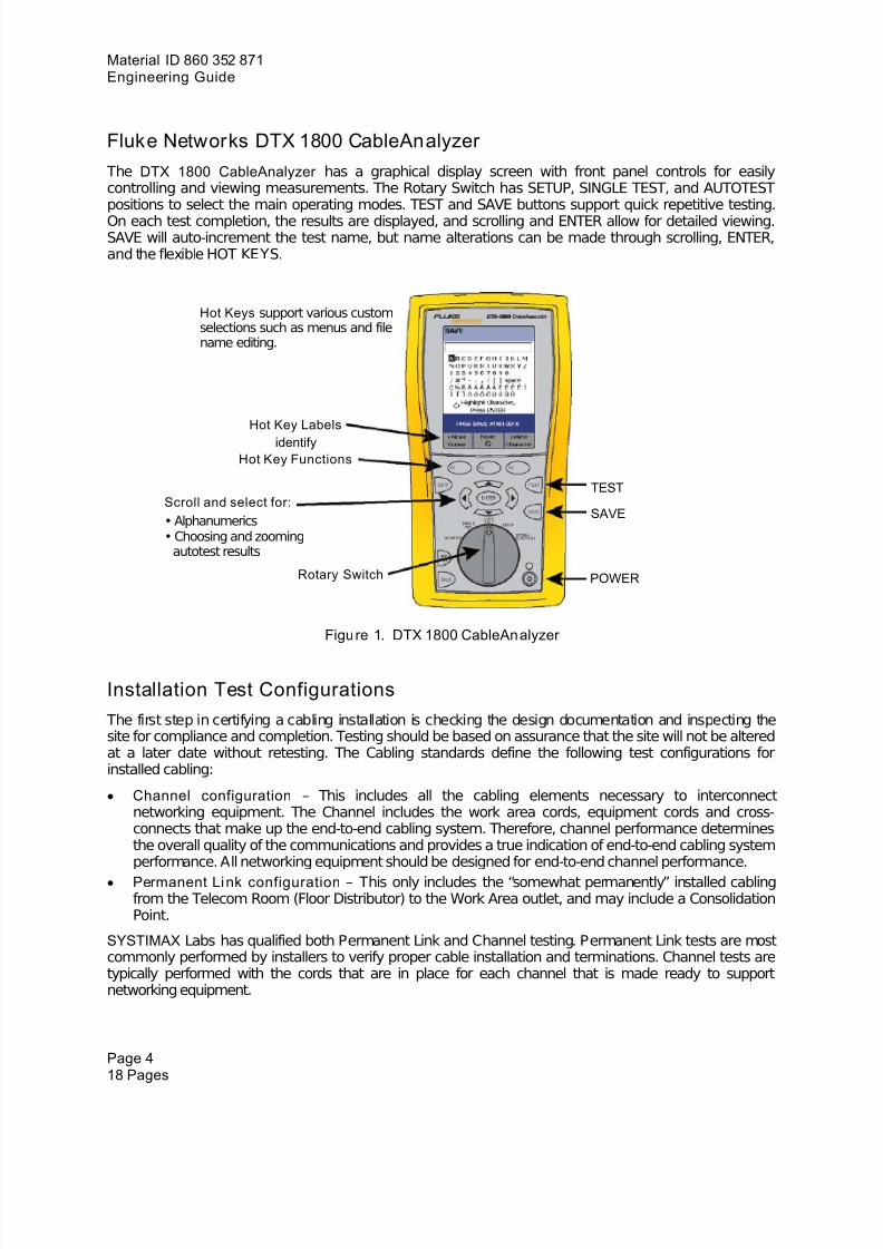
Fluke Networks DTX 1800 CableAnalyzer The DTX 1800 CableAnalyzer has a graphical display screen with front panel controls for easilycontrolling and viewing measurements. The Rotary Switch has SETUP, SINGLE TEST, and AUTOTESTpositions to select the main operating modes. TEST and SAVE buttons support quick repetitive testing.On each test completion, the results are displayed, and scrolling and ENTER allow for detailed viewing.SAVE will auto-increment the test name, but name alterations can be made through scrolling, ENTER,and the flexible HOT KEYS.
Hot Keys support various customselections such as menus and filename editing.
Hot Key Labelsidentify
Hot Key Functions
TEST
SAVEScroll and select for:• Alphanumerics• Choosing and zooming
autotest results
Rotary Switch POWER
Figure 1. DTX 1800 CableAnalyzer
Installation Test Configurations The first step in certifying a cabling installation is checking the design documentation and inspecting thesite for compliance and completion. Testing should be based on assurance that the site will not be alteredat a later date without retesting. The Cabling standards define the following test configurations forinstalled cabling:
• Channel configuration – This includes all the cabling elements necessary to interconnectnetworking equipment. The Channel includes the work area cords, equipment cords and cross-connects that make up the end-to-end cabling system. Therefore, channel performance determinesthe overall quality of the communications and provides a true indication of end-to-end cabling systemperformance. All networking equipment should be designed for end-to-end channel performance.
• Permanent Li nk configuration – This only includes the “somewhat permanently” installed cablingfrom the Telecom Room (Floor Distributor) to the Work Area outlet, and may include a ConsolidationPoint.
SYSTIMAX Labs has qualified both Permanent Link and Channel testing. Permanent Link tests are mostcommonly performed by installers to verify proper cable installation and terminations. Channel tests aretypically performed with the cords that are in place for each channel that is made ready to supportnetworking equipment.
Page 418 Pages
7/28/2019 860352871 Systimax Performance Verification Cableanalyzer Fluke
http://slidepdf.com/reader/full/860352871-systimax-performance-verification-cableanalyzer-fluke 5/18
Material ID 860 352 871Issue 1, December 2005
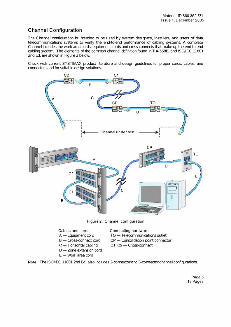
Channel Configuration The Channel configuration is intended to be used by system designers, installers, and users of datatelecommunications systems to verify the end-to-end performance of cabling systems. A completeChannel includes the work area cords, equipment cords and cross-connects that make up the end-to-endcabling system. The elements of the common channel definition found in TIA-568B, and ISO/IEC 11801
2nd Ed. are shown in Figure 2 below.Check with current SYSTIMAX product literature and design guidelines for proper cords, cables, andconnectors and for suitable design solutions.
C2 C1
B
C ATOCP
DE
Channel un der test
CP
TO A
D
C2E
CC1
B
Figure 2. Channel configuration
Cables and cords Connecting hardware A — Equipment cord TO — Telecommunications outletB — Cross-connect cord CP — Consolidation point connectorC — Horizontal cabling C1 , C2 — Cross-connectD — Zone extension cordE — Work area cord
Note: The ISO/IEC 11801 2nd Ed. also includes 2-connector and 3-connector channel configurations.
Page 518 Pages
7/28/2019 860352871 Systimax Performance Verification Cableanalyzer Fluke
http://slidepdf.com/reader/full/860352871-systimax-performance-verification-cableanalyzer-fluke 6/18
Material ID 860 352 871Engineering Guide
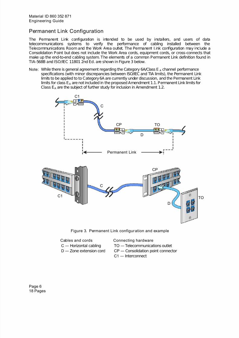
Permanent Link Configuration The Permanent Link configuration is intended to be used by installers, and users of datatelecommunications systems to verify the performance of cabling installed between the
Telecommunications Room and the Work Area outlet. The Permanent Link configuration may include aConsolidation Point but does not include the Work Area cords, equipment cords, or cross-connects that
make up the end-to-end cabling system. The elements of a common Permanent Link definition found in TIA-568B and ISO/IEC 11801 2nd Ed. are shown in Figure 3 below.
Note: While there is general agreement regarding the Category 6A/Class E A channel performancespecifications (with minor discrepancies between ISO/IEC and TIA limits), the Permanent Linklimits to be applied to to Category 6A are currently under discussion, and the Permanent Linklimits for class E A are not included in the proposed Amendment 1.1. Permanent Link limits forClass E A are the subject of further study for inclusion in Amendment 1.2.
C1
C
CP TO
D
Permanent Link
CP
C
C1 TOD
Figure 3. Permanent Link configur ation and example
Cables and cords Connecting hardwareC — Horizontal cabling TO — Telecommunications outletD — Zone extension cord CP — Consolidation point connector
C1 — Interconnect
Page 618 Pages
7/28/2019 860352871 Systimax Performance Verification Cableanalyzer Fluke
http://slidepdf.com/reader/full/860352871-systimax-performance-verification-cableanalyzer-fluke 7/18
Material ID 860 352 871Issue 1, December 2005
Field Testing of GigaSPEED X10D Installations with the Fluke NetworksDTX 1800 CableAnalyzer
The DTX 1800 CableAnalyzer is designed to verify Category 6A Channels and Permanent Links. Thecombination of main and remote units provide complete test results from both ends. Additionally, buildingbackbone channels and data center channels may also be tested according to these guidelines. In order
to perform accurate testing, it is important to follow the steps outlined below:
Step 1. – Verify that the latest Firmware is installed in the DTX CableAnalyzer.Step 2. – Select the correct Test Interface Adapters (used for the Calibration as well as for testing).Step 3. – Calibrate according to the recommendations from Fluke Networks (outlined below).Step 4. – Select and verify the correct NVP, select the correct Autotest for the configuration to be tested.Step 5. – Test, check, and save the result.
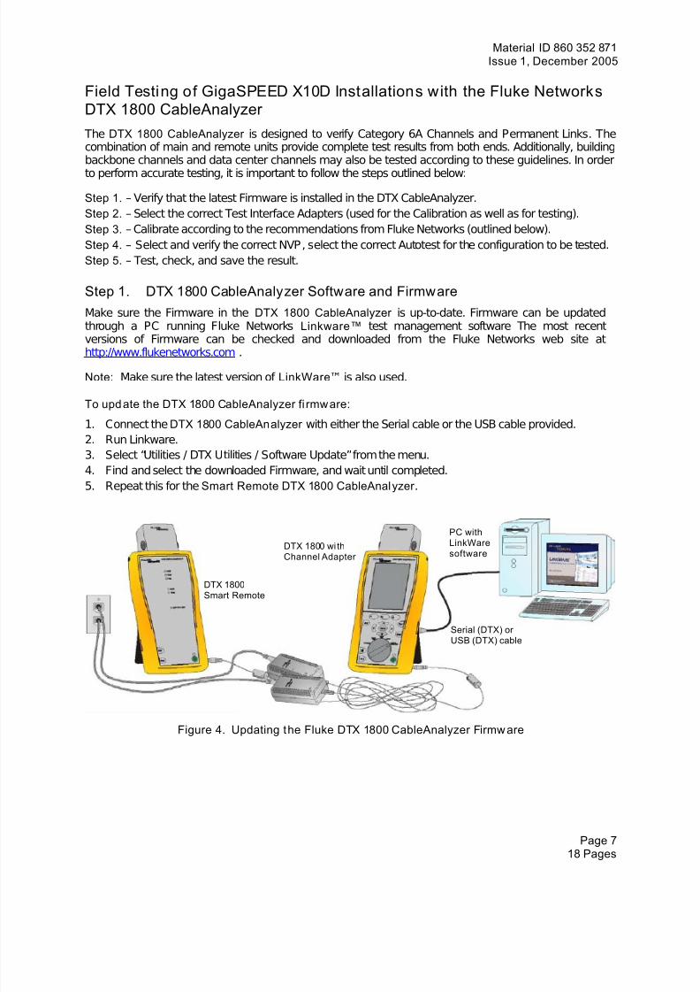
Step 1. DTX 1800 CableAnalyzer Software and FirmwareMake sure the Firmware in the DTX 1800 CableAnalyzer is up-to-date. Firmware can be updatedthrough a PC running Fluke Networks Linkware™ test management software The most recentversions of Firmware can be checked and downloaded from the Fluke Networks web site athttp://www.flukenetworks.com .
Note: Make sure the latest version of LinkWare ™ is also used.
To upd ate the DTX 1800 CableAnalyzer fi rmw are:
1. Connect the DTX 1800 CableAnalyzer with either the Serial cable or the USB cable provided.2. Run Linkware.3. Select “Utilities / DTX Utilities / Software Update” from the menu.4. Find and select the downloaded Firmware, and wait until completed.5. Repeat this for the Smart Remote DTX 1800 CableAnalyzer .
PC withLinkWaresoftware
DTX 1800 wi thChannel Adapter
DTX 1800Smart Remote
Serial (DTX) or USB (DTX) cable
Figure 4. Updating the Fluke DTX 1800 CableAnalyzer Firmw are
Page 718 Pages
7/28/2019 860352871 Systimax Performance Verification Cableanalyzer Fluke
http://slidepdf.com/reader/full/860352871-systimax-performance-verification-cableanalyzer-fluke 8/18
Material ID 860 352 871Engineering Guide
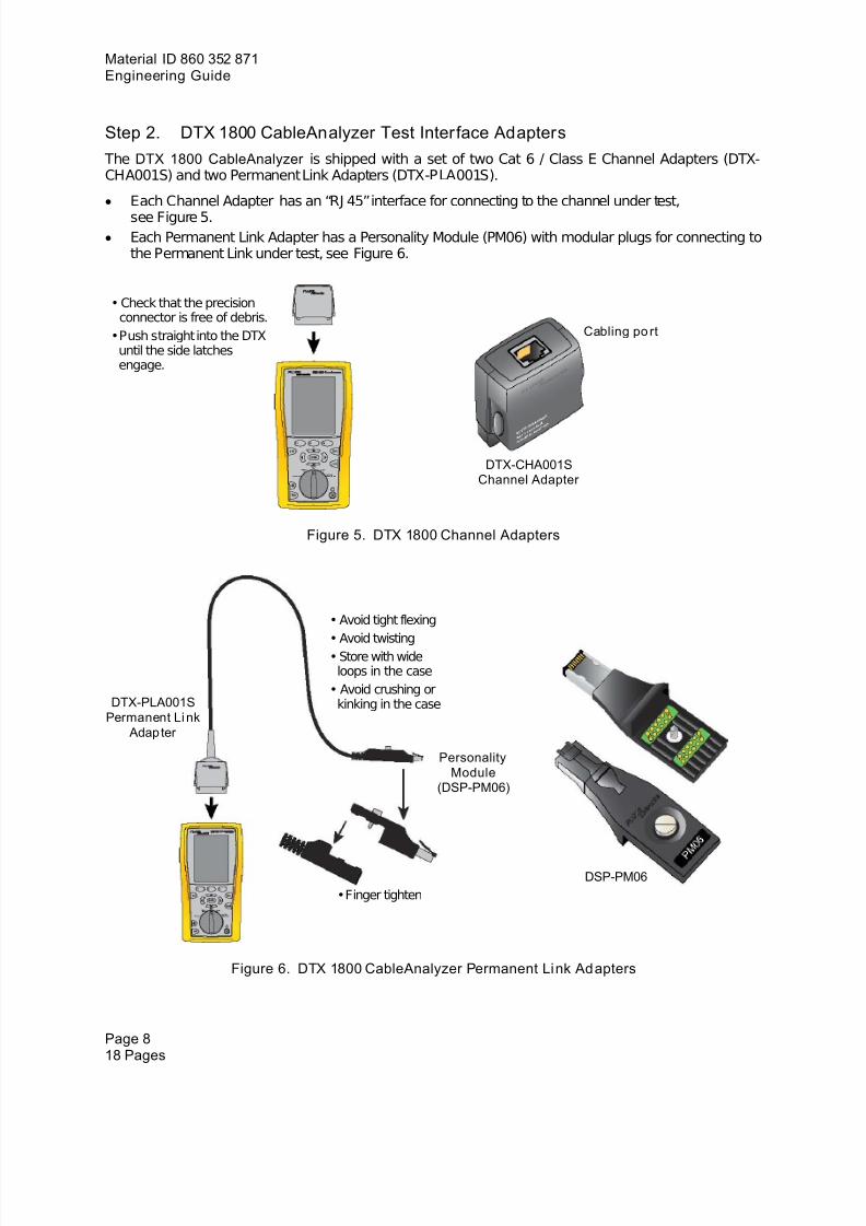
Step 2. DTX 1800 CableAnalyzer Test Interface Adapters The DTX 1800 CableAnalyzer is shipped with a set of two Cat 6 / Class E Channel Adapters (DTX-CHA001S) and two Permanent Link Adapters (DTX-PLA001S).
• Each Channel Adapter has an “RJ 45” interface for connecting to the channel under test,see Figure 5.
• Each Permanent Link Adapter has a Personality Module (PM06) with modular plugs for connecting tothe Permanent Link under test, see Figure 6.
• Check that the precisionconnector is free of debris.
• Push straight into the DTXuntil the side latchesengage.
Cabling po rt
DTX-CHA001SChannel Adapter
Figure 5. DTX 1800 Channel Adapters
• Avoid tight flexing
• Avoid twisting• Store with wideloops in the case
• Avoid crushing orkinking in the caseDTX-PLA001S
Pe krmanent Li n Adap ter
PersonalityModule
(DSP-PM06)
DSP-PM06 • Finger tighten
Figure 6. DTX 1800 CableAnalyzer Permanent Link Adapters
Page 818 Pages
7/28/2019 860352871 Systimax Performance Verification Cableanalyzer Fluke
http://slidepdf.com/reader/full/860352871-systimax-performance-verification-cableanalyzer-fluke 9/18
Material ID 860 352 871Issue 1, December 2005
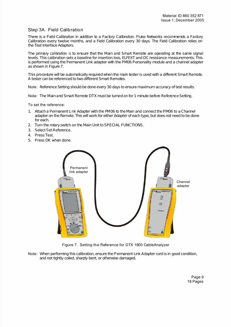
Step 3A. Field Calibration There is a Field Calibration in addition to a Factory Calibration. Fluke Networks recommends a FactoryCalibration every twelve months, and a Field Calibration every 30 days. The Field Calibration relies onthe Test Interface Adapters.
The primary calibration is to ensure that the Main and Smart Remote are operating at the same signallevels. This calibration sets a baseline for insertion loss, ELFEXT and DC resistance measurements. Thisis performed using the Permanent Link adapter with the PM06 Personality module and a channel adapteras shown in Figure 7.
This procedure will be automatically required when the main tester is used with a different Smart Remote.A tester can be referenced to two different Smart Remotes.
Note: Reference Setting should be done every 30 days to ensure maximum accuracy of test results.
Note: The Main and Smart Remote DTX must be turned on for 1 minute before Reference Setting.
To set the reference:
1. Attach a Permanent Link Adapter with the PM06 to the Main and connect the PM06 to a Channeladapter on the Remote. This will work for either Adapter of each type, but does not need to be donefor each.
2. Turn the rotary switch on the Main Unit to SPECIAL FUNCTIONS.3. Select Set Reference.4. Press Test.5. Press OK when done.
Permanent
link adapter
Channeladapter
Figure 7. Setting th e Reference for DTX 1800 CableAnalyzer
Note: When performing this calibration, ensure the Permanent Link Adapter cord is in good condition,and not tightly coiled, sharply bent, or otherwise damaged.
Page 918 Pages
7/28/2019 860352871 Systimax Performance Verification Cableanalyzer Fluke
http://slidepdf.com/reader/full/860352871-systimax-performance-verification-cableanalyzer-fluke 10/18
Material ID 860 352 871Engineering Guide
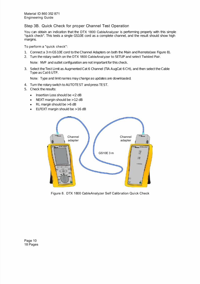
Step 3B. Quick Check for proper Channel Test Operation You can obtain an indication that the DTX 1800 CableAnalyzer is performing properly with this simple"quick check". This tests a single GS10E cord as a complete channel, and the result should show highmargins.
To perform a "quick check":
1. Connect a 3 m GS10E cord to the Channel Adapters on both the Main and Remote(see Figure 8) .2. Turn the rotary switch on the DTX 1800 CableAnalyzer to SETUP and select Twisted Pair.
Note: NVP and outlet configuration are not important for this check.
3. Select the Test Limit as Augmented Cat 6 Channel (TIA AugCat 6 CH), and then select the Cable Type as Cat 6 UTP.
Note: Type and limit names may change as updates are downloaded.
4. Turn the rotary switch to AUTOTEST and press TEST.5. Check the results:
• Insertion Loss should be <2 dB• NEXT margin should be >12 dB• RL margin should be >6 dB• ELFEXT margin should be >16 dB
Channeladapter
Channeladapter
GS10E 3 m
Figure 8. DTX 1800 CableAnalyzer Self Calibr ation Quick Check
Page 1018 Pages
7/28/2019 860352871 Systimax Performance Verification Cableanalyzer Fluke
http://slidepdf.com/reader/full/860352871-systimax-performance-verification-cableanalyzer-fluke 11/18
Material ID 860 352 871Issue 1, December 2005
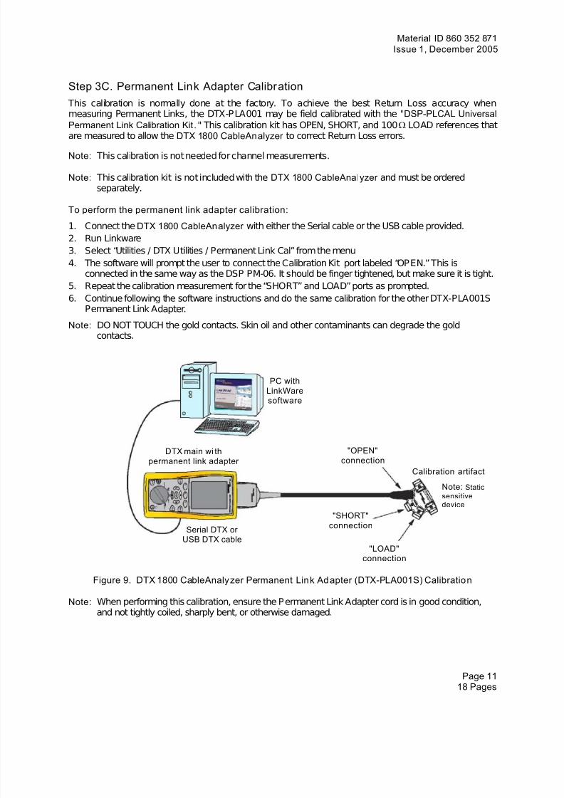
Step 3C. Permanent Link Adapter Calibration This calibration is normally done at the factory. To achieve the best Return Loss accuracy whenmeasuring Permanent Links, the DTX-PLA001 may be field calibrated with the " DSP-PLCAL UniversalPermanent Link Calibration Kit . " This calibration kit has OPEN, SHORT, and 100 Ω LOAD references that
are measured to allow the DTX 1800 CableAnalyzer to correct Return Loss errors.Note: This calibration is not needed for channel measurements.
Note: This calibration kit is not included with the DTX 1800 CableAnalyzer and must be orderedseparately.
To perform the permanent link adapter calibration:
1. Connect the DTX 1800 CableAnalyzer with either the Serial cable or the USB cable provided.2. Run Linkware3. Select “Utilities / DTX Utilities / Permanent Link Cal” from the menu4. The software will prompt the user to connect the Calibration Kit port labeled “OPEN.” This is
connected in the same way as the DSP PM-06. It should be finger tightened, but make sure it is tight.5. Repeat the calibration measurement for the “SHORT” and LOAD” ports as prompted.6. Continue following the software instructions and do the same calibration for the other DTX-PLA001S
Permanent Link Adapter.
Note: DO NOT TOUCH the gold contacts. Skin oil and other contaminants can degrade the goldcontacts.
PC withLinkWaresoftware
"OPEN"connection
DTX main wi thpermanent link adapter
Calibration artifact
Note: Staticsensitivedevice
"SHORT"connectionSerial DTX or
USB DTX cable"LOAD"
connection
Figure 9. DTX 1800 CableAnalyzer Permanent Link Adapter (DTX-PLA001S) Calibration
Note: When performing this calibration, ensure the Permanent Link Adapter cord is in good condition,and not tightly coiled, sharply bent, or otherwise damaged.
Page 1118 Pages
7/28/2019 860352871 Systimax Performance Verification Cableanalyzer Fluke
http://slidepdf.com/reader/full/860352871-systimax-performance-verification-cableanalyzer-fluke 12/18
Material ID 860 352 871Engineering Guide
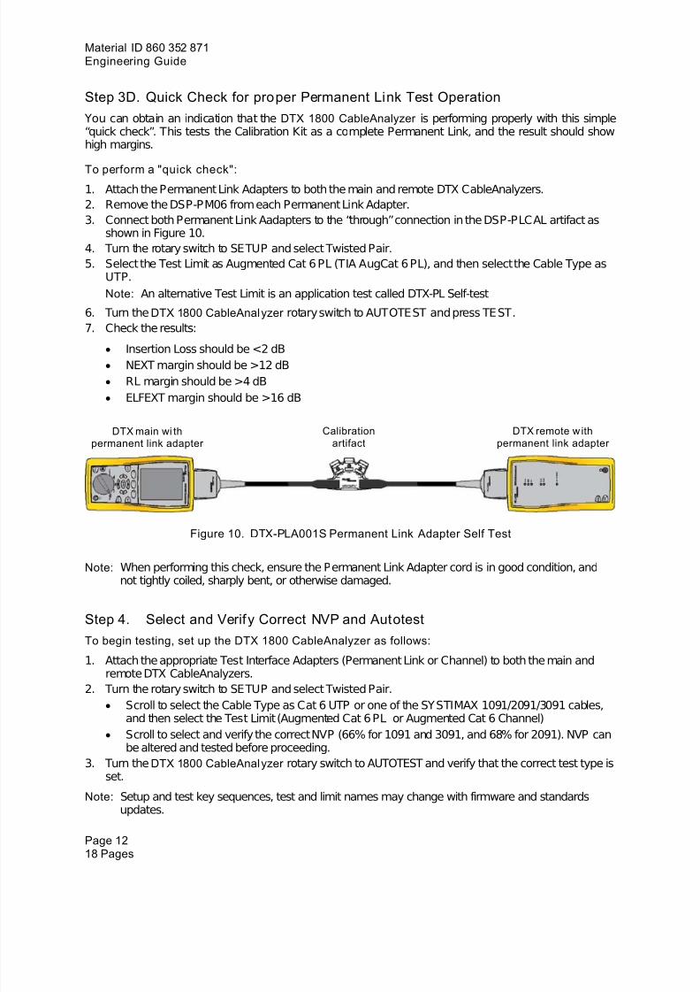
Step 3D. Quick Check for proper Permanent Link Test Operation You can obtain an indication that the DTX 1800 CableAnalyzer is performing properly with this simple“quick check”. This tests the Calibration Kit as a complete Permanent Link, and the result should showhigh margins.
To perform a "quick check":1. Attach the Permanent Link Adapters to both the main and remote DTX CableAnalyzers.2. Remove the DSP-PM06 from each Permanent Link Adapter.3. Connect both Permanent Link Aadapters to the “through” connection in the DSP-PLCAL artifact as
shown in Figure 10. 4. Turn the rotary switch to SETUP and select Twisted Pair.5. Select the Test Limit as Augmented Cat 6 PL (TIA AugCat 6 PL), and then select the Cable Type as
UTP.Note: An alternative Test Limit is an application test called DTX-PL Self-test
6. Turn the DTX 1800 CableAnalyzer rotary switch to AUTOTEST and press TEST.7. Check the results:
• Insertion Loss should be <2 dB• NEXT margin should be >12 dB• RL margin should be >4 dB• ELFEXT margin should be >16 dB
Calibrationartifact
DTX remote w ithpermanent link adapter
DTX main wi thpermanent link adapter
Figure 10. DTX-PLA001S Permanent Link Adapter Self Test
Note: When performing this check, ensure the Permanent Link Adapter cord is in good condition, andnot tightly coiled, sharply bent, or otherwise damaged.
Step 4. Select and Verify Correct NVP and AutotestTo begin testing, set up the DTX 1800 CableAnalyzer as follows:
1. Attach the appropriate Test Interface Adapters (Permanent Link or Channel) to both the main andremote DTX CableAnalyzers.
2. Turn the rotary switch to SETUP and select Twisted Pair.• Scroll to select the Cable Type as Cat 6 UTP or one of the SYSTIMAX 1091/2091/3091 cables,
and then select the Test Limit (Augmented Cat 6 PL or Augmented Cat 6 Channel)• Scroll to select and verify the correct NVP (66% for 1091 and 3091, and 68% for 2091). NVP can
be altered and tested before proceeding.3. Turn the DTX 1800 CableAnalyzer rotary switch to AUTOTEST and verify that the correct test type is
set.
Note: Setup and test key sequences, test and limit names may change with firmware and standardsupdates.
Page 1218 Pages
7/28/2019 860352871 Systimax Performance Verification Cableanalyzer Fluke
http://slidepdf.com/reader/full/860352871-systimax-performance-verification-cableanalyzer-fluke 13/18
Material ID 860 352 871Issue 1, December 2005
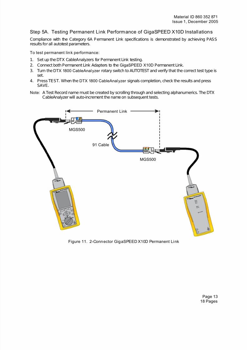
Step 5A. Testing Permanent Link Performance of GigaSPEED X10D InstallationsCompliance with the Category 6A Permanent Link specifications is demonstrated by achieving PASSresults for all autotest parameters.
To test permanent lin k performance:
1. Set up the DTX CableAnalyzers for Permanent Link testing.2. Connect both Permanent Link Adapters to the GigaSPEED X10D Permanent Link.3. Turn the DTX 1800 CableAnalyzer rotary switch to AUTOTEST and verify that the correct test type is
set.4. Press TEST. When the DTX 1800 CableAnalyzer signals completion, check the results and press
SAVE.
Note: A Test Record name must be created by scrolling through and selecting alphanumerics. The DTXCableAnalyzer will auto-increment the name on subsequent tests.
Permanent Link
MGS500
91 Cable
MGS500
Figure 11. 2-Conn ector GigaSPEED X10D Permanent Li nk
Page 1318 Pages
7/28/2019 860352871 Systimax Performance Verification Cableanalyzer Fluke
http://slidepdf.com/reader/full/860352871-systimax-performance-verification-cableanalyzer-fluke 14/18
Material ID 860 352 871Engineering Guide
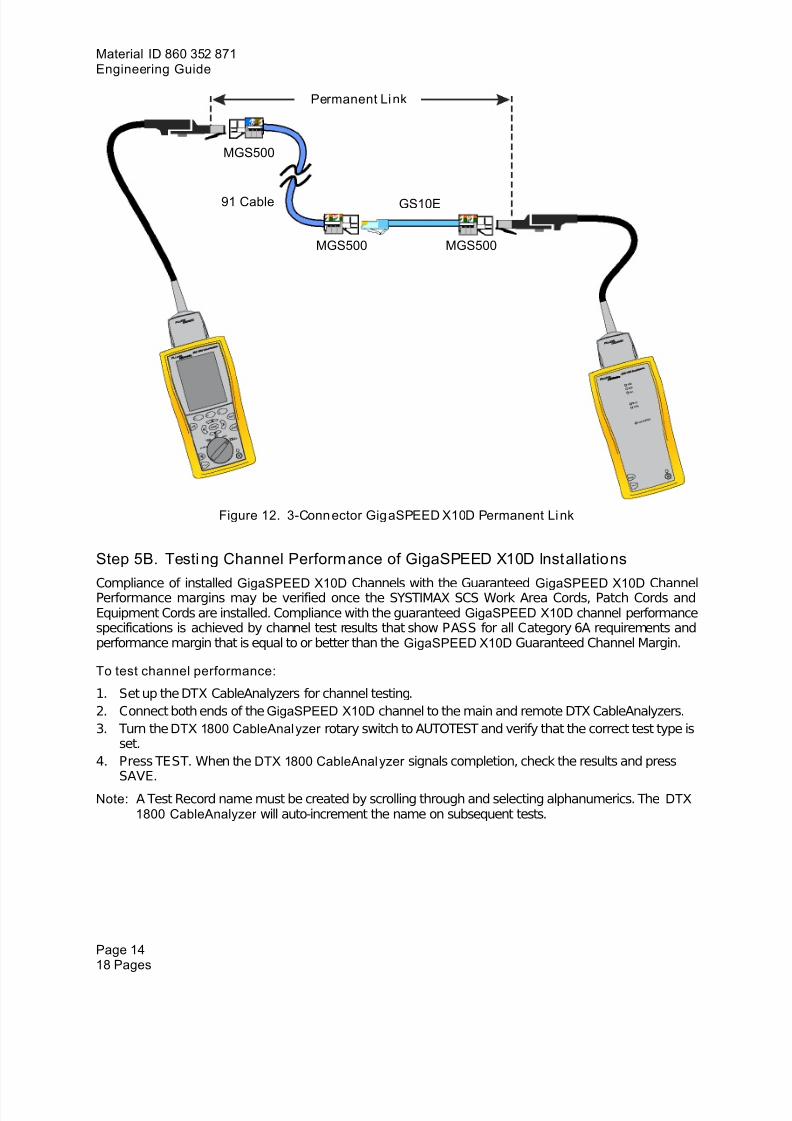
Permanent Li nk
MGS500
91 Cable GS10E
MGS500 MGS500
Figure 12. 3-Conn ector GigaSPEED X10D Permanent Li nk
Step 5B. Testing Channel Performance of GigaSPEED X10D Installations
Compliance of installed GigaSPEED X10D Channels with the Guaranteed GigaSPEED X10D ChannelPerformance margins may be verified once the SYSTIMAX SCS Work Area Cords, Patch Cords andEquipment Cords are installed. Compliance with the guaranteed GigaSPEED X10D channel performancespecifications is achieved by channel test results that show PASS for all Category 6A requirements andperformance margin that is equal to or better than the GigaSPEED X10D Guaranteed Channel Margin.
To test channel performance:
1. Set up the DTX CableAnalyzers for channel testing.2. Connect both ends of the GigaSPEED X10D channel to the main and remote DTX CableAnalyzers.3. Turn the DTX 1800 CableAnalyzer rotary switch to AUTOTEST and verify that the correct test type is
set.4. Press TEST. When the DTX 1800 CableAnalyzer signals completion, check the results and press
SAVE.
Note: A Test Record name must be created by scrolling through and selecting alphanumerics. The DTX1800 CableAnalyzer will auto-increment the name on subsequent tests.
Page 1418 Pages
7/28/2019 860352871 Systimax Performance Verification Cableanalyzer Fluke
http://slidepdf.com/reader/full/860352871-systimax-performance-verification-cableanalyzer-fluke 15/18
Material ID 860 352 871Issue 1, December 2005
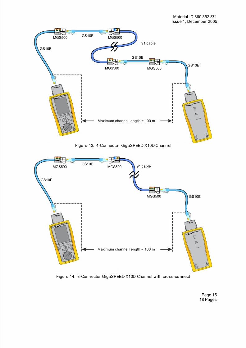
GS10E MGS500MGS500
91 cableGS10E
GS10E
GS10EMGS500 MGS500
Maximum channel leng th = 100 m
Figure 13. 4-Connec tor GigaSPEED X10D Channel
GS10E91 cableMGS500 MGS500
GS10E
MGS500 GS10E
Maximum channel l ength = 100 m
Figure 14. 3-Connector GigaSPEED X10D Channel wi th cro ss-connect
Page 1518 Pages
7/28/2019 860352871 Systimax Performance Verification Cableanalyzer Fluke
http://slidepdf.com/reader/full/860352871-systimax-performance-verification-cableanalyzer-fluke 16/18
Material ID 860 352 871Engineering Guide
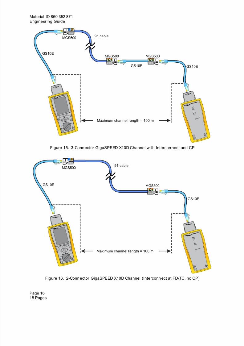
91 cableMGS500
GS10EMGS500 MGS500
GS10E GS10E
Maximum channel l ength = 100 m
Figure 15. 3-Connector GigaSPEED X10D Channel wit h Intercon nect and CP
91 cableMGS500
GS10E MGS500
GS10E
Maximum channel l ength = 100 m
Figure 16. 2-Connector GigaSPEED X10D Channel (Interconn ect at FD/TC, no CP)
Page 1618 Pages
7/28/2019 860352871 Systimax Performance Verification Cableanalyzer Fluke
http://slidepdf.com/reader/full/860352871-systimax-performance-verification-cableanalyzer-fluke 17/18
Material ID 860 352 871Issue 1, December 2005
Uploading Test ResultsTo upload test results:
1. Connect the DTX 1800 CableAnalyzer with either the serial cable or the USB cable provided.2. Run LinkWare.3. Select "File/Import from/DTX CableAnalyzer" from the menu.4. Choose the Autotest results.5. Use various features of LinkWare to view and sort results.6. Select "File/Save As" from the menu.
Troubleshooting Links and Channels The DTX 1800 CableAnalyzer automatically troubleshoots many problems. Some problems require youto manually run and examine diagnostic tests.
Typical problems include the following:
• A Conduc tor or Pair is Open
The wiremap problem along with estimated cable distance is displayed. This is typically at aconnection, and the open can be easily identified and fixed.
• A Pair ’s Polari ty i s Reversed or Pairs are Swapp ed
The problem is displayed but there is no way to tell where the error is, so you must check eachconnection for proper termination.
• NEXT Fails
The DTX 1800 CableAnalyzer will run an additional measurement, HDTDX. This displays theNEXT as a plot over the distance of the channel. Typically, the largest NEXT contribution showsup at a connection near the failing end and can be fixed with a retermination.
• Return Loss Fails
The DTX 1800 CableAnalyzer will run an additional measurement, HDTDR. This displays the RLas a plot over the distance of the channel. Typically, the largest RL contribution shows up at aconnection and can be fixed with a retermination.
• At tenuat ion Fails
Usually one of the other parameters can help identify the location of the problem. This can alsofail if the Link or Channel is too long, or if the wrong test standard is selected.
• ELFEXT Fails
Usually NEXT and HDTDX can help identify the location of the problem.
Page 1718 Pages
7/28/2019 860352871 Systimax Performance Verification Cableanalyzer Fluke
http://slidepdf.com/reader/full/860352871-systimax-performance-verification-cableanalyzer-fluke 18/18
Material ID 860 352 871Engineering Guide
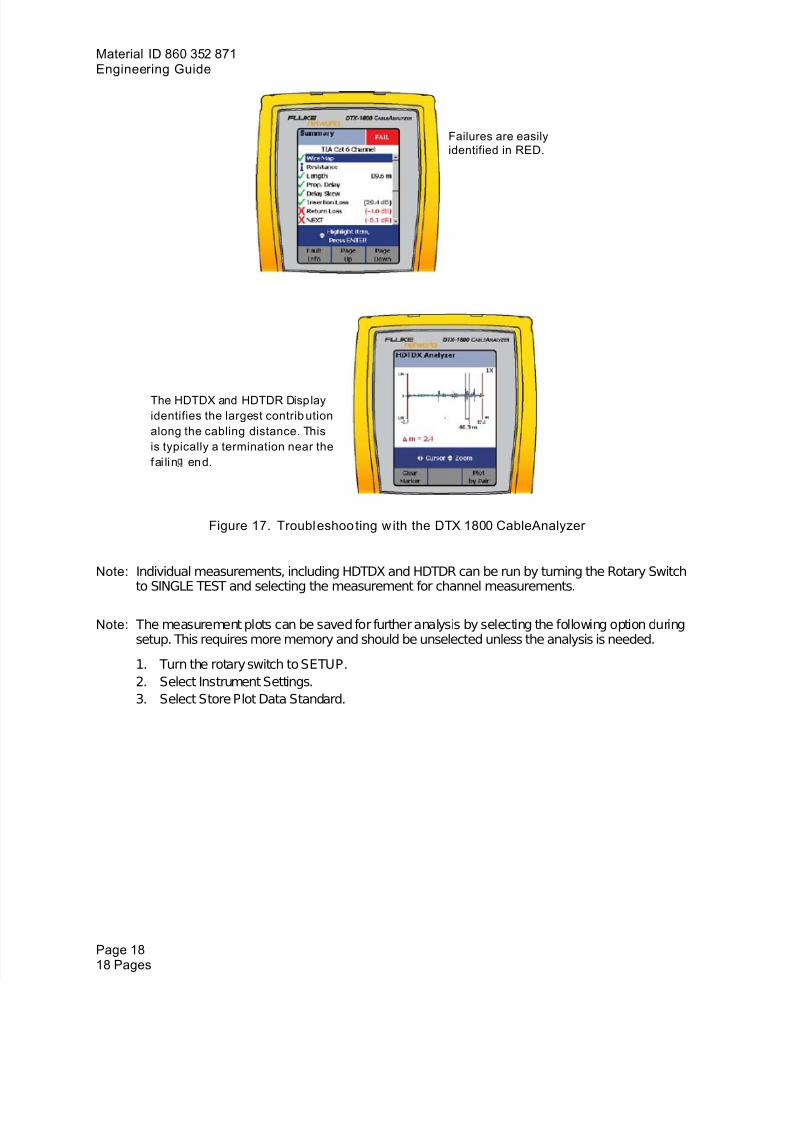
Failures are easilyidentified in RED.
The HDTDX and HDTDR Disp layidentifies the largest contrib utionalong the cabling distance. Thisis typically a termination near thefai lin end.
Figure 17. Troubleshoo ting w ith the DTX 1800 CableAnalyzer
Note: Individual measurements, including HDTDX and HDTDR can be run by turning the Rotary Switch
to SINGLE TEST and selecting the measurement for channel measurements.
Note: The measurement plots can be saved for further analysis by selecting the following option duringsetup. This requires more memory and should be unselected unless the analysis is needed.
1. Turn the rotary switch to SETUP.2. Select Instrument Settings.3. Select Store Plot Data Standard.
Page 1818 Pages
Related Documents


