Part No. AS609 (Rev A) 85R-4P Compressed Air System Installation/User Guide Operation & Maintenance Manual ® Registered Trademark/™ Trademark of JUN-AIR Inc. ©Copyright 2012 JUN-AIR Manufacturing Inc. All Rights Reserved. WWW.JUN-AIR.COM ISO 9001 CERTIFIED

Welcome message from author
This document is posted to help you gain knowledge. Please leave a comment to let me know what you think about it! Share it to your friends and learn new things together.
Transcript

Part No. AS609 (Rev A)
85R-4P Compressed Air SystemInstallation/User GuideOperation & Maintenance Manual
® Registered Trademark/™ Trademark of JUN-AIR Inc. ©Copyright 2012 JUN-AIR Manufacturing Inc. All Rights Reserved.
WWW.JUN-AIR.COM
ISO 9001 CERTIFIED
2
AS609 (Rev A) 85R-4P Compressor System User Guide
© 2012, JUN-AIRWe reserve the right to make any alterations which may be due to any technical improvements
Printed in the USA
WARNING
PLEASE READ THIS MANUAL COMPLETELY BEFORE INSTALLING AND USING
THIS PRODUCT. SAVE THIS MANUAL FOR FUTURE REFERENCE AND
KEEP IN THE VICINITY OF THE PRODUCT.
Dear Customer:
Congratulations on the purchase of your new Jun-Air Industrial Compressed Air System.
This system’s intended purpose is for industrial and laboratory compression applications. It is to be used in accordance with UL1450/CSA 22.2 standards, along with all applicable codes. The system utilizes an oil-less rocking piston com-pressor that produces clean, dry, oil-free pres-surized air flow when connected to an industrial or laboratory device. The tank ensures that a constant supply of air is available to the device.
IMPORTANT SAFETY INSTRUCTIONS AND REGULATORY INFORMATION
A pressure regulator and safety relief valve is also included to ensure safe operation of the system. This manual provides installation, opera-tion and preventative maintenance guidelines that should be followed to ensure correct/reliable performance of this system.
Please complete the warranty card and return to Jun-Air for registration. Please carry out all maintenance according to relevant instructions.
TABLE OF CONTENTS
Important Safety Instructions and Regulatory Information . . . . . . . . . . . . . . . . . . . . . . . . . . . . . . . . . . 3-4System Features . . . . . . . . . . . . . . . . . . . . . . . . . . . . . . . . . . . . . . . . . . . . . . . . . . . . . . . . . . . . . . . . .5Internal Features . . . . . . . . . . . . . . . . . . . . . . . . . . . . . . . . . . . . . . . . . . . . . . . . . . . . . . . . . . . . . . . . .6Unpacking . . . . . . . . . . . . . . . . . . . . . . . . . . . . . . . . . . . . . . . . . . . . . . . . . . . . . . . . . . . . . . . . . . . . . .7Installation
Safety Data . . . . . . . . . . . . . . . . . . . . . . . . . . . . . . . . . . . . . . . . . . . . . . . . . . . . . . . . . . . . . . . . 8-9Site Requirements . . . . . . . . . . . . . . . . . . . . . . . . . . . . . . . . . . . . . . . . . . . . . . . . . . . . . . . . . . . .10Pneumatic Connections . . . . . . . . . . . . . . . . . . . . . . . . . . . . . . . . . . . . . . . . . . . . . . . . . . . . . . . .11Electrical Connections . . . . . . . . . . . . . . . . . . . . . . . . . . . . . . . . . . . . . . . . . . . . . . . . . . . . . . . . .11Pneumatic Schematic . . . . . . . . . . . . . . . . . . . . . . . . . . . . . . . . . . . . . . . . . . . . . . . . . . . . . . . . .12Electrical Schematic . . . . . . . . . . . . . . . . . . . . . . . . . . . . . . . . . . . . . . . . . . . . . . . . . . . . . . . . . . .13System Checks and Tests . . . . . . . . . . . . . . . . . . . . . . . . . . . . . . . . . . . . . . . . . . . . . . . . . . . . . .14
Operation . . . . . . . . . . . . . . . . . . . . . . . . . . . . . . . . . . . . . . . . . . . . . . . . . . . . . . . . . . . . . . . . . . . . . .15Specifications . . . . . . . . . . . . . . . . . . . . . . . . . . . . . . . . . . . . . . . . . . . . . . . . . . . . . . . . . . . . . . . . . .16Maintenance . . . . . . . . . . . . . . . . . . . . . . . . . . . . . . . . . . . . . . . . . . . . . . . . . . . . . . . . . . . . . . . . 17-18Troubleshooting . . . . . . . . . . . . . . . . . . . . . . . . . . . . . . . . . . . . . . . . . . . . . . . . . . . . . . . . . . . . . . . . .19Warranty . . . . . . . . . . . . . . . . . . . . . . . . . . . . . . . . . . . . . . . . . . . . . . . . . . . . . . . . . . . . . . . . . . . . . .20Options & Accessories . . . . . . . . . . . . . . . . . . . . . . . . . . . . . . . . . . . . . . . . . . . . . . . . . . . . . . . . . . .21Installation Checklist . . . . . . . . . . . . . . . . . . . . . . . . . . . . . . . . . . . . . . . . . . . . . . . . . . . . . . . . . . . . . .22Notes . . . . . . . . . . . . . . . . . . . . . . . . . . . . . . . . . . . . . . . . . . . . . . . . . . . . . . . . . . . . . . . . . . . . . . . .23

3© 2012, JUN-AIRWe reserve the right to make any alterations which may be due to any technical improvementsPrinted in the USA
85R-4P Compressor System User Guide AS609 (Rev A)
TABLE OF SYMBOLS
Electrical shock hazardRisk of electric shock present. Make surepower is disconnected before attemptingthis procedure.
CAUTION: Indicates a potentially hazardoussituation which may result in minor ormoderate injury if not avoided. It may also beused to alert against unsafe practices.
WARNING: To Avoid Serious Burns:Do not touch surface during operation.
Indicates the ON and OFF position for the Equipment power Switch
ON OFF
IO
Indicates package should be handled with these symbols pointing up.
FRAGILE: Handle package with care.
Indicates this package must be kept dry.
Indicates the acceptable shipping temperature range.
-29 °C-20 °F
+50 °C+122 °F
Indicates the acceptable maximum relative humidity for shipping.
95
Indicates the acceptable lowest barometricpressure conditions in which this unit canbe shipped.372MM HG
.49 ATM
INDUSTRIAL ELECTRICAL EQUIPMENT
With respect to electrical shock, fire, mechanical and other specified hazards only in accordance with UL1450.
Symbol DescriptionA/C power
Air outlet port
Fuse location
Ground
Hour meter
Over-temp indicator light
Power on indicator light
Pressure gauge
Pressure regulator valve

4
AS609 (Rev A) 85R-4P Compressor System User Guide
© 2012, JUN-AIRWe reserve the right to make any alterations which may be due to any technical improvements
Printed in the USA
INTENDED USE:To provide compressed air for use with industrial or laboratory devices as a primary or back-up air source .
Jun-Air compressor systems meet or exceed the most current and highest safety standards, which are:
• UL1450, 4th edition
• CSA C22.2 68
• ISO 9001:2008
• Ingress protection: IP50
To ensure the safety potential of this equipment is achieved, please:
Make sure your equipment is installed according to the instructions provided in this manual and make sure the installation checklist is completed prior to starting the equipment .
DANGER: The equipment is not suitable for use in the presence of a flammable anes-thetic mixture or with oxygen or nitrous oxide . DO NOT OPERATE THE EQUIPMENT IF THESE CONDITIONS EXIST.
Protection against electrical shock:Provide proper grounding per NFPA 70 (NEC 2008) . Do not become a current path from the equipment to ground through your body .
Transportation/Storage Conditions:Temperature range -28 °C/-4 °F to 65 °C /149 °F . Relative Humidity 10% to 95% (non-condensing) . Barometric pressure minimum of 372 mm Hg (49 ATM)
Keep system dry at all times .
Do not stack units during shipment or installation .
Important: Refer servicing to an authorized service representative.
IMPORTANT SAFETY INSTRUCTIONS AND REGULATORY INFORMATION

5© 2012, JUN-AIRWe reserve the right to make any alterations which may be due to any technical improvementsPrinted in the USA
85R-4P Compressor System User Guide AS609 (Rev A)
SYSTEM FEATURES
6
AS609 (Rev A) 85R-4P Compressor System User Guide
© 2012, JUN-AIRWe reserve the right to make any alterations which may be due to any technical improvements
Printed in the USA
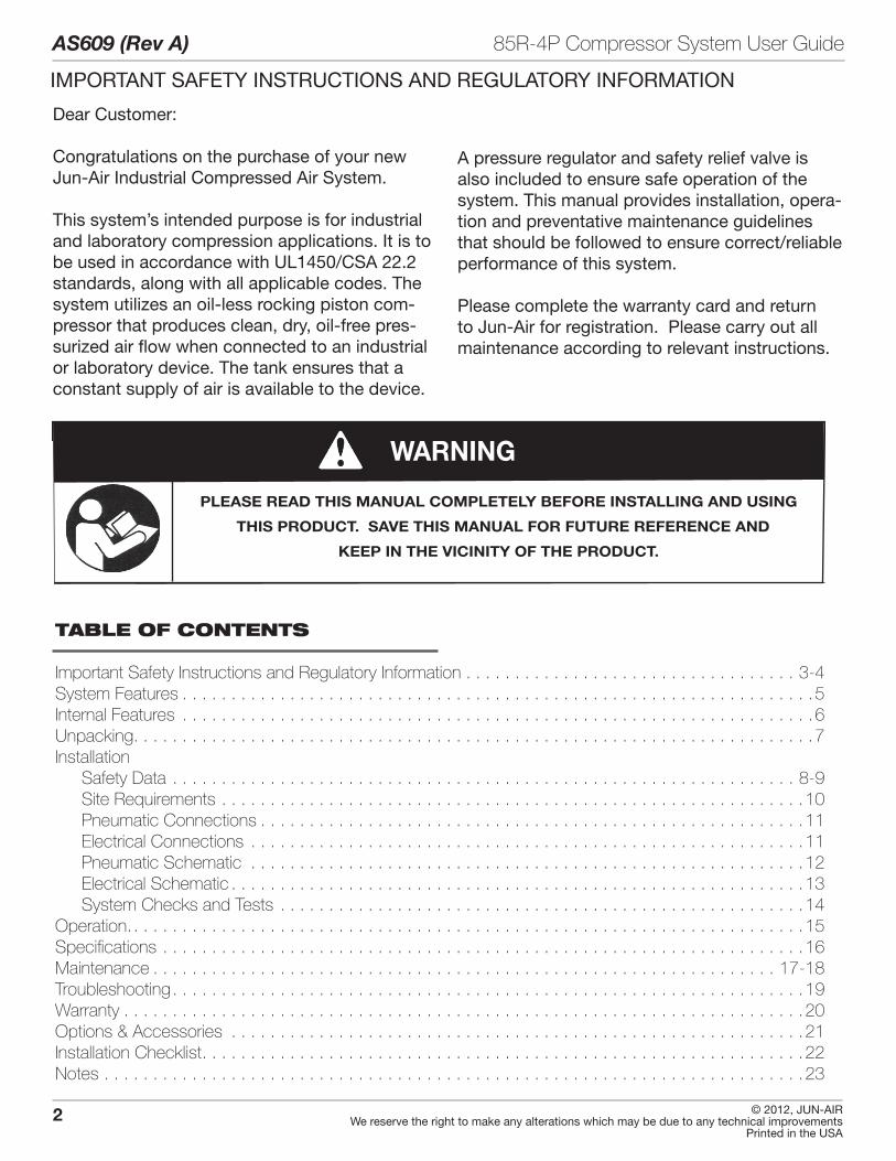
INTERNAL FEATURES

7© 2012, JUN-AIRWe reserve the right to make any alterations which may be due to any technical improvementsPrinted in the USA
85R-4P Compressor System User Guide AS609 (Rev A)
UNPACKING
1 . Examine contents for damage prior to removing shipping carton .
a . If shipping damage is found, immediately contact the freight carrier to file a claim .
2 . Remove banding strap from carton .
3 . Remove carton top and note accessory bag .
4 . Remove top retaining and side inserts .
5 . Visually inspect the entire compressor system for shipping damage .
a . If shipping damage is found, immediately contact the freight carrier to file a claim .
NOTE: If parts are missing, contact the supplier .
6 . Using caution, remove compressor system from remaining packaging . Retain packaging material for future use, if necessary .
REMINDER! Fill out and return warranty and registration card.
8
AS609 (Rev A) 85R-4P Compressor System User Guide
© 2012, JUN-AIRWe reserve the right to make any alterations which may be due to any technical improvements
Printed in the USA
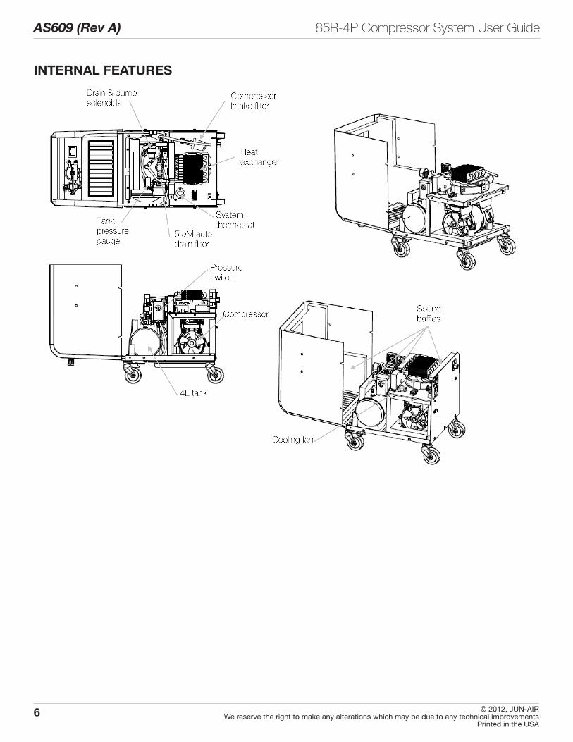
PERSONAL SAFETY:
DANGER: Danger of fire or explosion when using flammable substances. Do not operate the compressor in an area containing combustible gases or anesthetic mixtures.
CAUTION: Never leave children unattended near compressor when in use.
WARNING: Property damage and/or personal injury may result if directions are not followed or manufacturer’s replacement parts/accessories are not used.
WARNING: Connect only equipment suitable for listed maximum pressure of the compressor.
WARNING: DO NOT install on surfaces with more than a 10o incline.
WARNING: If unit is operating in high altitude, adjustments to time, temperature or pressure may be required. Consult service technician prior to making any adjustments.
WARNING: A leaking pressure relief valve may indicate a need for adjustment or repair. Consult service technician prior to making any adjustments.
PLACEMENT:• Indoor use only
• Dust free, climate controlled room
• DO NOT install/operate in an enclosed area where ambient temperature could exceed tem-perature specifications of below 10 °C/50 °F, or above 40 °C/104 °F .
• Maintain minimum 12" clearance on all sides and top of all compressors for service access and cooling .
• Ensure unit stands level and firmly on the floor.
INSTALLATION SAFETY DATA
Indicates the ON and OFF position for the equipment power switch (system breaker)
When ON, the indicator light will illuminate and voltage WILL be supplied to system.
When OFF, the indicator light will NOT illuminate and voltage WILL NOT be supplied to the system.
I
o= ON
= OFF
I o
9© 2012, JUN-AIRWe reserve the right to make any alterations which may be due to any technical improvementsPrinted in the USA
85R-4P Compressor System User Guide AS609 (Rev A)
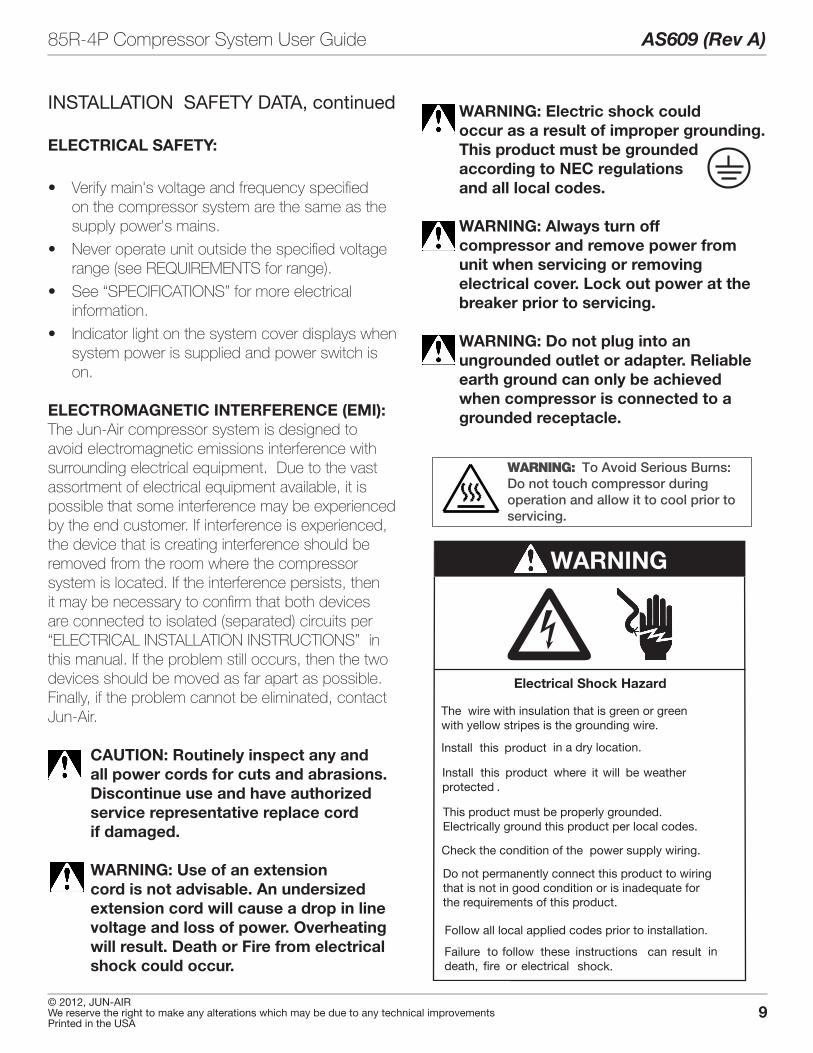
CAUTION: Routinely inspect any and all power cords for cuts and abrasions. Discontinue use and have authorized service representative replace cord if damaged.
WARNING: Use of an extension cord is not advisable. An undersized extension cord will cause a drop in line voltage and loss of power. Overheating will result. Death or Fire from electrical shock could occur.
ELECTRICAL SAFETY:
• Verify main's voltage and frequency specified on the compressor system are the same as the supply power's mains.
• Never operate unit outside the specified voltage range (see REQUIREMENTS for range) .
• See “SPECIFICATIONS” for more electrical information .
• Indicator light on the system cover displays when system power is supplied and power switch is on .
ELECTROMAGNETIC INTERFERENCE (EMI):The Jun-Air compressor system is designed to avoid electromagnetic emissions interference with surrounding electrical equipment . Due to the vast assortment of electrical equipment available, it is possible that some interference may be experienced by the end customer . If interference is experienced, the device that is creating interference should be removed from the room where the compressor system is located . If the interference persists, then it may be necessary to confirm that both devices are connected to isolated (separated) circuits per “ELECTRICAL INSTALLATION INSTRUCTIONS” in this manual . If the problem still occurs, then the two devices should be moved as far apart as possible . Finally, if the problem cannot be eliminated, contact Jun-Air .
INSTALLATION SAFETY DATA, continued
�Install this product
Install this product where it will be weatherprotected .
Failure to follow these instructions can result indeath, fire or electrical shock.
Electrical Shock Hazard
WARNING
This product must be properly grounded. Electrically ground this product per local codes.
Follow all local applied codes prior to installation.
Do not permanently connect this product to wiring that is not in good condition or is inadequate forthe requirements of this product.
Check the condition of the power supply wiring.
The wire with insulation that is green or greenwith yellow stripes is the grounding wire.
in a dry location.
WARNING: To Avoid Serious Burns:Do not touch compressor during operation and allow it to cool prior to servicing.
WARNING: Electric shock could occur as a result of improper grounding. This product must be grounded according to NEC regulations and all local codes.
WARNING: Always turn off compressor and remove power from unit when servicing or removing electrical cover. Lock out power at the breaker prior to servicing.
WARNING: Do not plug into an ungrounded outlet or adapter. Reliable earth ground can only be achieved when compressor is connected to a grounded receptacle.
10
AS609 (Rev A) 85R-4P Compressor System User Guide
© 2012, JUN-AIRWe reserve the right to make any alterations which may be due to any technical improvements
Printed in the USA
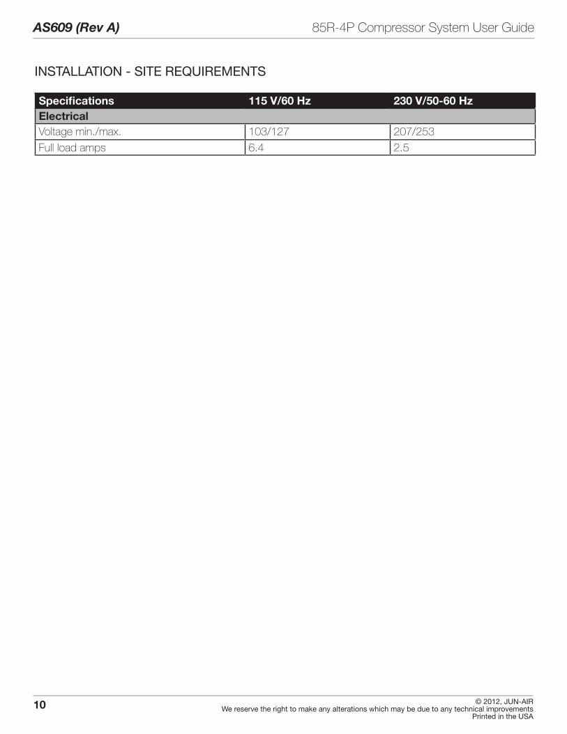
INSTALLATION - SITE REQUIREMENTS
Specifications 115 V/60 Hz 230 V/50-60 HzElectricalVoltage min ./max . 103/127 207/253
Full load amps 6 .4 2 .5
11© 2012, JUN-AIRWe reserve the right to make any alterations which may be due to any technical improvementsPrinted in the USA
85R-4P Compressor System User Guide AS609 (Rev A)
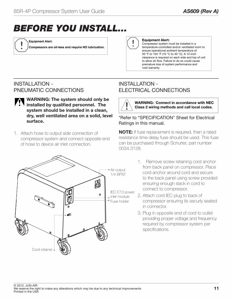
INSTALLATION - PNEUMATIC CONNECTIONS
BEFORE YOU INSTALL...Equipment Alert:
Compessors are oil-less and require NO lubrication.
Equipment Alert:Compressor system must be installed in a temperature-controlled and/or ventilated room toensure operational ambient temperature of 50 °F to 104 °F (10 °C to 40 °C). A 12-inch clearance is required on each side and top of unitto allow air flow. Failure to do so could causepremature loss of system performance andvoid warranty.
WARNING: The system should only be installed by qualified personnel. The system should be installed in a clean, dry, well ventilated area on a solid, level surface.
1 . Attach hose to output side connection of compressor system and connect opposite end of hose to device air inlet connection .
INSTALLATION - ELECTRICAL CONNECTIONS
WARNING: Connect in accordance with NEC Class 2 wiring methods and call local codes.
*Refer to “SPECIFICATION" Sheet for Electrical Ratings in this manual.
NOTE: If fuse replacement is required, then a rated resistance time-delay fuse should be used . This fuse can be purchased through Schurter, part number 0034 .3128 .
1 . Remove screw retaining cord anchor from back panel on compressor . Place cord anchor around cord and secure to the back panel using screw provided ensuring enough slack in cord to connect to compressor .
2 . Attach cord IEC plug to back of compressor ensuring its securly seated in connector .
3 . Plug in opposite end of cord to outlet providing proper voltage and frequency required by compressor system per specifications .
Cord retainer
Air output1/4 BPST
Fuse holder
IEC C13 powerinlet module
12
AS609 (Rev A) 85R-4P Compressor System User Guide
© 2012, JUN-AIRWe reserve the right to make any alterations which may be due to any technical improvements
Printed in the USA
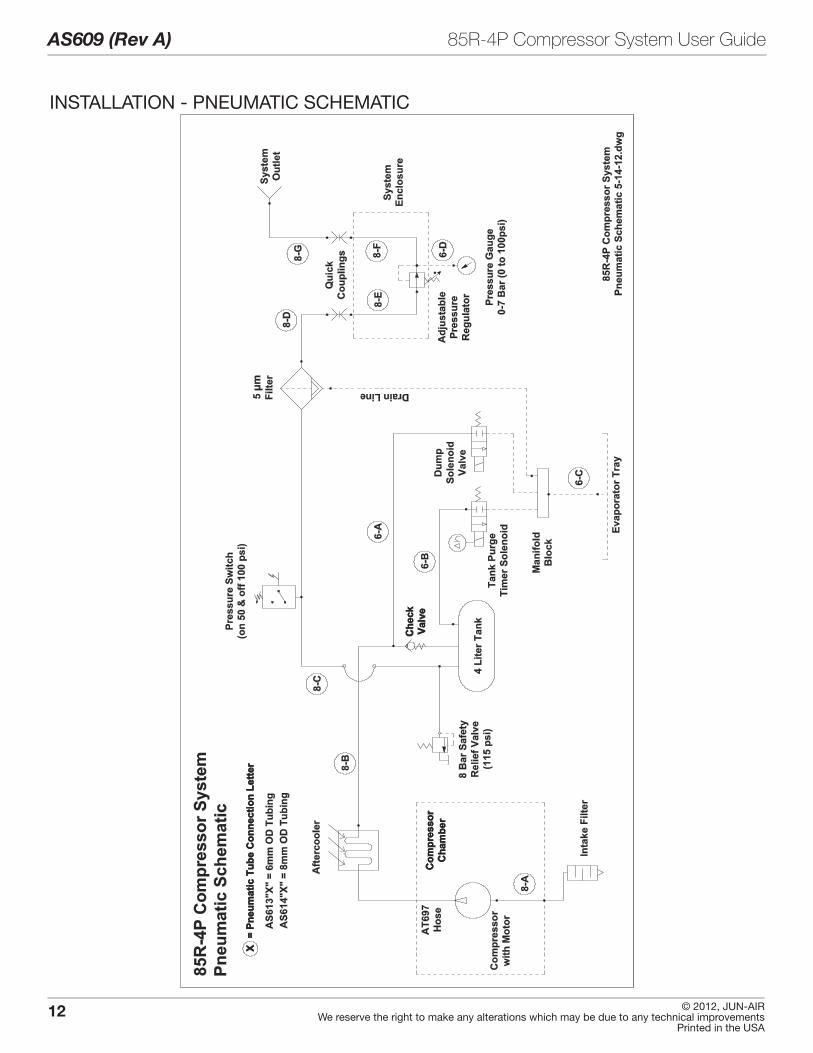
INSTALLATION - PNEUMATIC SCHEMATIC

13© 2012, JUN-AIRWe reserve the right to make any alterations which may be due to any technical improvementsPrinted in the USA
85R-4P Compressor System User Guide AS609 (Rev A)
INSTALLATION - ELECTRICAL SCHEMATIC

14
AS609 (Rev A) 85R-4P Compressor System User Guide
© 2012, JUN-AIRWe reserve the right to make any alterations which may be due to any technical improvements
Printed in the USA
SYSTEM CHECKS AND TESTS
Equipment Alert: Verify all leaks are sealed. Air leaks are main cause of premature compressor failures.
1 . Turn power on . The compressor should run and the storage tank will begin to pressurize .
WARNING: Always turn off compressor and remove power when removing system cover.
2 . Check the incoming line voltage . It should be a minimum of 103 or 207 volts and should not exceed 127 or 253 volts . This voltage should remain within this range while compressor system is running . If voltage does not remain within the specified range, contact Jun-Air .
NOTES: • System safety relief valve set to 8 bar [115 psi].
• System pressure switch set to max. 7 bar [100 psi] cutout, and 4 bar [60 psi] cut in.
• Monitor line pressure gauge when testing for leaks .
• You may use soapy water to check for any pressure leaks .
NOTE: If the internal tank pressure gauge drops more than 5 psi, an air leak exists. Locate the leak(s) and repair .
System Recover time (60 psi to 100 psi)
Pump-up time (0 to max. pressure)
Max. pressure
115 V or 230 V < 15 sec . < 35 sec . 100 psi ±3 psi

15© 2012, JUN-AIRWe reserve the right to make any alterations which may be due to any technical improvementsPrinted in the USA
85R-4P Compressor System User Guide AS609 (Rev A)
OPERATION
1 . Once the compressor system is completely installed and ready for operation, it can be turned on using the power switch on the back panel . A light on the compressor cover will turn on to indicate that voltage is supplied to the compressor, and the system is operational .
2 . The system will provide clean and dry air and is factory preset to operate approximately at 4 to 7 bar [60 to 100 psi] (see "SPECIFICATIONS"). If this setting needs to be adjusted, contact your authorized dealer . Use the adjustable knob on the front cover to adjust output air pressure .
3 . When the compressor system is not in use, it should be powered down by turning it off, using the power switch on the back panel . (Pressure must be released from the system before transporting or removing connections) . The indicator light on the compressor cover will turn off once the switch is turned off .
Power switch
Pressure switch
Output pressuregauge
Pressureregulatoradjustment
Airintakescreen

16
AS609 (Rev A) 85R-4P Compressor System User Guide
© 2012, JUN-AIRWe reserve the right to make any alterations which may be due to any technical improvements
Printed in the USA
Specifications 115 V / 60 Hz 230 V / 50 Hz to 60 Hz
Continuous SystemOutput Flow
56lpm @ 3bar(2 .0 CFM @ 40psi)
60 lpm @ 3 bar [60 Hz](2.1 CFM @ 40 psi) [60 Hz]52 lpm @ 3 bar [50 Hz](1.8 CFM @ 40 psi) [50 Hz]
Cut-in Pressure (compressor ON - adjustable)
4 bar [60 psi] 4 bar [60 psi]
Cut-out Pressure (compressor OFF - adjustable)
7 bar [100 psi] 7 bar [100 psi]
Maximum Compressor Output Pressure (adjustable)
7 bar [100 psi] 7 bar [100 psi]
Dew Point Suppression n/a n/aAir Filtration 5μ 5μSafety Relief Valve Pressure 7.9 bar [115 psi] 7.9 bar [115 psi]High Temperature Indication ≥ 60 °C [140 °F]
compressor chamber≥ 60 °C [140 °F] compressor chamber
Air Connections 1/4" BSPT 1/4" BSPTVoltage/Frequency 115 V - 60 Hz 230 V - 50/60 HzCurrent 6 .4 amps 2 .6/2 .5 amps (50/60 Hz)Power Consumption < 640 W < 580/550 W (50/60 Hz)Fuse Size (Amps) 12 .5 TD 12 .5 TDSound Level (dBA) ≤ 51 @ 100 psi ≤ 50 @ 100 psi [50 Hz]
≤ 52 @ 100 psi [60 Hz]Operating Ambient Conditions 10 °C to 40 °C [50 °F to 104 °F]
10 - 95% RH (non-condensing)10 °C to 40 °C [50 °F to 104 °F] 10 - 95% RH (non-condensing)
Storage Ambient Conditions -20 °C to 65 °C [-4 °F to 149 °F] 10 to 95% RH (non-condensing)
-20 °C to 65 °C (-4 °F to 149 °F] 10 - 95% RH (non-condensing]
System Dimensions W x H x D 406 mm x 495 mm x 439 mm [16" W x 19.5" D x 17.3" H]
406 mm x 495 mm x 439 mm [16" W x 19.5" D x 17.3" H]
System Weight 29.5 kg [65 lb] 29.5 kg [65 lb]System Shipping Weight 35 kg [77 lb] 35 kg [77 lb]Agency Compliance & Approvals UL1450 / CSA 22.2 / CE UL1450 / CSA 22.2 / CE
17© 2012, JUN-AIRWe reserve the right to make any alterations which may be due to any technical improvementsPrinted in the USA
85R-4P Compressor System User Guide AS609 (Rev A)
MAINTENANCE
By performing regularly scheduled maintenance, you will ensure your compressor system provides you with years of superior performance .
Also to extend your compressor system life, please do the following:
• Keep compressor system clean and free of dirt and debris .
• Keep area surrounding compressor system clean and free of debris .
• Maintain recommended controlled ambient temperature – high temperatures will shorten life .
• Verify all leaks are sealed.
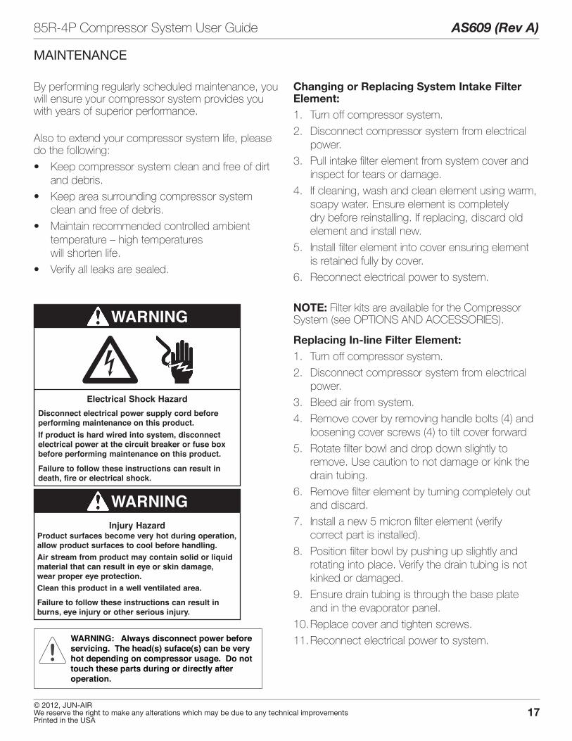
�Disconnect electrical power supply cord beforeperforming maintenance on this product.If product is hard wired into system, disconnectelectrical power at the circuit breaker or fuse boxbefore performing maintenance on this product.
Failure to follow these instructions can result indeath, fire or electrical shock.
Electrical Shock Hazard
WARNING
Injury HazardProduct surfaces become very hot during operation,allow product surfaces to cool before handling.Air stream from product may contain solid or liquidmaterial that can result in eye or skin damage,wear proper eye protection.Clean this product in a well ventilated area.
Failure to follow these instructions can result inburns, eye injury or other serious injury.
WARNING
Changing or Replacing System Intake Filter Element:1 . Turn off compressor system .
2 . Disconnect compressor system from electrical power .
3 . Pull intake filter element from system cover and inspect for tears or damage .
4 . If cleaning, wash and clean element using warm, soapy water . Ensure element is completely dry before reinstalling . If replacing, discard old element and install new .
5 . Install filter element into cover ensuring element is retained fully by cover .
6 . Reconnect electrical power to system .
NOTE: Filter kits are available for the Compressor System (see OPTIONS AND ACCESSORIES) .
Replacing In-line Filter Element:1 . Turn off compressor system .
2 . Disconnect compressor system from electrical power .
3 . Bleed air from system .
4 . Remove cover by removing handle bolts (4) and loosening cover screws (4) to tilt cover forward
5 . Rotate filter bowl and drop down slightly to remove . Use caution to not damage or kink the drain tubing .
6 . Remove filter element by turning completely out and discard .
7 . Install a new 5 micron filter element (verify correct part is installed) .
8 . Position filter bowl by pushing up slightly and rotating into place . Verify the drain tubing is not kinked or damaged .
9 . Ensure drain tubing is through the base plate and in the evaporator panel .
10 . Replace cover and tighten screws .
11 . Reconnect electrical power to system .WARNING: Always disconnect power beforeservicing. The head(s) suface(s) can be veryhot depending on compressor usage. Do nottouch these parts during or directly afteroperation.
18
AS609 (Rev A) 85R-4P Compressor System User Guide
© 2012, JUN-AIRWe reserve the right to make any alterations which may be due to any technical improvements
Printed in the USA
MAINTENANCE (continued)
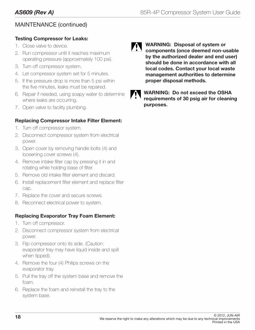
WARNING: Disposal of system or components (once deemed non-usable by the authorized dealer and end user) should be done in accordance with all local codes. Contact your local waste management authorities to determine proper disposal methods.
WARNING: Do not exceed the OSHA requirements of 30 psig air for cleaning purposes.
Testing Compressor for Leaks:1 . Close valve to device .
2 . Run compressor until it reaches maximum operating pressure (approximately 100 psi) .
3 . Turn off compressor system .
4. Let compressor system set for 5 minutes.
5 . If the pressure drop is more than 5 psi within the five minutes, leaks must be repaired .
6 . Repair if needed, using soapy water to determine where leaks are occurring .
7 . Open valve to facility plumbing .
Replacing Compressor Intake Filter Element:1 . Turn off compressor system .
2 . Disconnect compressor system from electrical power .
3 . Open cover by removing handle bolts (4) and loosening cover screws (4) .
4 . Remove intake filter cap by pressing it in and rotating while holding base of filter .
5 . Remove old intake filter element and discard .
6 . Install replacement filter element and replace filter cap .
7 . Replace the cover and secure screws .
8 . Reconnect electrical power to system .
Replacing Evaporator Tray Foam Element:1 . Turn off compressor .
2 . Disconnect compressor system from electrical power .
3 . Flip compressor onto its side . (Caution: evaporator tray may have liquid inside and spill when tipped) .
4 . Remove the four (4) Philips screws on the evaporator tray .
5 . Pull the tray off the system base and remove the foam .
6 . Replace the foam and reinstall the tray to the system base .

19© 2012, JUN-AIRWe reserve the right to make any alterations which may be due to any technical improvementsPrinted in the USA
85R-4P Compressor System User Guide AS609 (Rev A)
TROUBLESHOOTING CHART
Problem Possible Cause(s) Possible Solution(s)1 . Motor/compressor does not
starta . No electric power a . Check circuit breaker at main power
source .
b . Power not connected b . Check
c . Defective power switch c . Power switch needs to be replaced . Call your authorized dealer for service . Check compressor power switch is in the ON position .
d . Fuse is blown/damaged d . Check fuse(s) in electrical inlet .
2 . Motor tries to start, circuit breaker trips
a . Voltage too low . If each compressor head runs separately, but not togeth-er, the voltage is too low .
a . Compressor requires a minimum of 208 volts . If the voltage is too below required minimum, a buck-boost transformer must be installed .
b . Solenoid valve does not open when compression cycle ends .
b . Check the solenoid valve . If it does not open at the end of the cycle, call autho-rized dealer for service .
c . Power supply cable too small c . See SITE REQUIREMENTS .
d. Loose electrical connection d . Call authorized dealer for service .
3 . Unusual or excessive noise a . Intake filter(s) not seated correctly a . Remove filter(s) and replace if clogged or dirty . When installing, make sure filter cham-ber is clean and filter is sealed properly .
b . Intake filter(s) clogged or dirty b . Replace filter(s) .
c . Motor or compressor noise c . Call authorized dealer for service .
d . Air leaks d . Close the storage tank outlet valve . Check all fittings for leaks . If leak is found, call authorized dealer for service .
e . Check cooling fan e . If fan is loose or broken, call authorized dealer for service .
4 . Compressor cycles but does not build up pressure to 100 psi
a . Solenoid valve does not close or leaks when compressor runs
a . Check the solenoid valve . Call authorized dealer for service .
b . Clogged or dirty intake filters b . Replace intake filters .
c. Leak in compressor system c . Close the storage tank outlet valve . Check all fittings for leaks . If leak is found, call authorized dealer for service. (See “Testing Compressor for Leaks” in MAINTENANCE section .)
d. Leak in device air system d . With the power switch ON, ensure the compressors are running . Close the stor-age tank outlet valve and wait for the com-pressor system to shut off at 100 psi . Wait 5 minutes and open the storage tank outlet valve . If the pressure drops (by more than 5 psi or the compressors start again) the leak is in the office air lines or delivery units . Contact your authorized dealer for service .
e . Pressure switch out of adjustment e . Call authorized dealer for service or detailed instructions to adjust pressure switch .
20
AS609 (Rev A) 85R-4P Compressor System User Guide
© 2012, JUN-AIRWe reserve the right to make any alterations which may be due to any technical improvements
Printed in the USA
WARRANTY POLICY
If within the warranty time limits described below, the compressor system or any of its com-ponents fail under normal use and service, the original user-owner must contact an autho-rized Jun-Air dealer with the product sale and service records . Should the dealer not be able to complete the repair, the dealer may contact Jun-Air for disposition . The product’s model and serial number, the installation date and the Jun-Air invoice number must be furnished . Transportation charges both ways must be paid by the dealer . If upon receipt at the factory, an examination reveals faulty or defective original parts, materials, or workmanship, Jun-Air will, at its sole option, rebuild or replace . This warranty does not cover damages caused by misuse, abuse, accident, or neglect . Unauthorized alterations or repairs made outside our factory will cancel this warranty and charges for them will not be allowed .
COMPRESSOR SYSTEMSAll compressor systems sold and installed by authorized Jun-Air dealers are warranted to be free from defects in parts, workmanship, and materials for 8,000 hours of operation or two (2) years from date of purchase, whichever occurs first .
This warranty excludes normal expected service items such as but not limited to: filters/filter kits, o-rings, and hoses . It also excludes add-on accessories that carry their own specific manufacturer’s warranty .
21© 2012, JUN-AIRWe reserve the right to make any alterations which may be due to any technical improvementsPrinted in the USA
85R-4P Compressor System User Guide AS609 (Rev A)
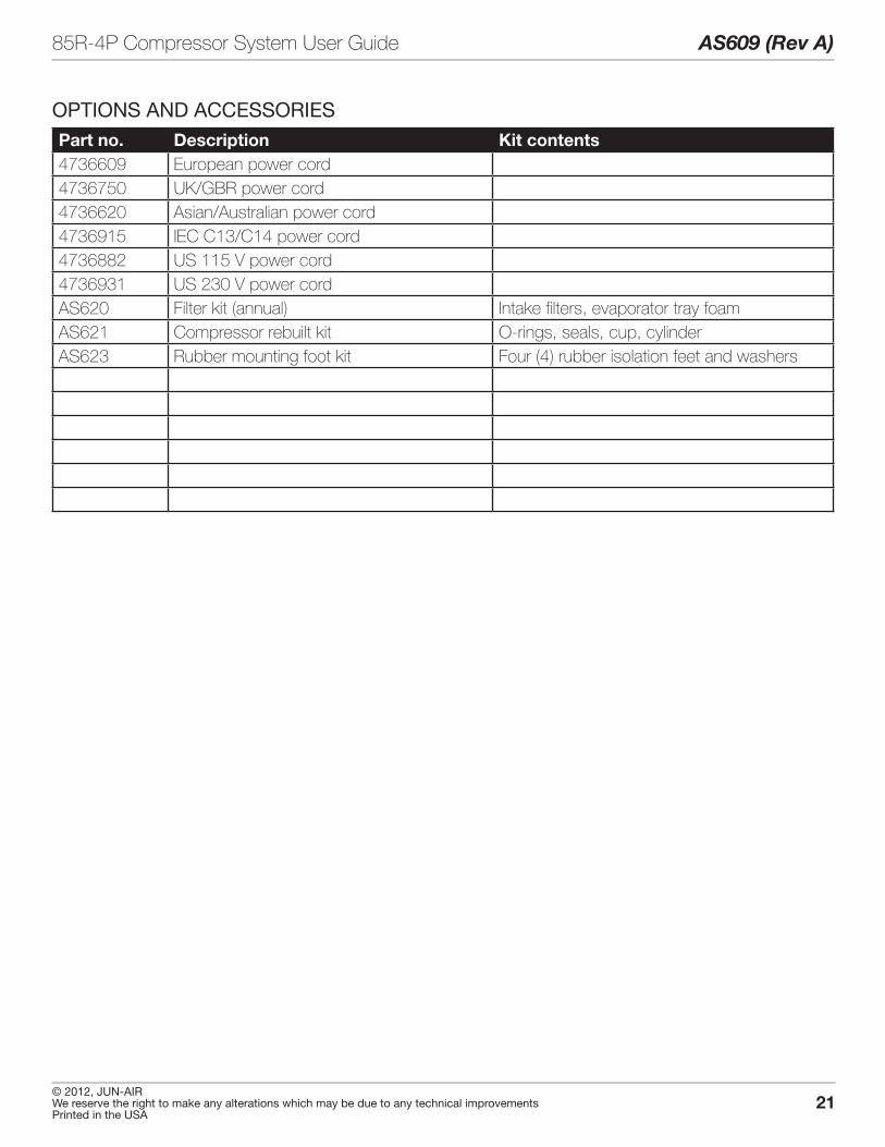
OPTIONS AND ACCESSORIESPart no. Description Kit contents4736609 European power cord4736750 UK/GBR power cord4736620 Asian/Australian power cord4736915 IEC C13/C14 power cord4736882 US 115 V power cord4736931 US 230 V power cordAS620 Filter kit (annual) Intake filters, evaporator tray foamAS621 Compressor rebuilt kit O-rings, seals, cup, cylinderAS623 Rubber mounting foot kit Four (4) rubber isolation feet and washers

22
AS609 (Rev A) 85R-4P Compressor System User Guide
© 2012, JUN-AIRWe reserve the right to make any alterations which may be due to any technical improvements
Printed in the USA
INSTALLATION CHECKLIST
o Check system for shipping damage
o Remove packaging cardboard
o Verify installation kit components
o Relocate unit to operating location and place per “SITE REQUIREMENTS”
o Attach pneumatic fittings and connections per “SITE REQUIREMENTS” and “INSTALLATION PNEUMATIC CONNECTIONS”.
o Attach electrical connections per “SITE REQUIREMENTS” and “INSTALLATION - ELECTRICAL" Requirements
o Verify incoming line voltage meets minimum and maximum values
o Turn on power to dedicated circuit and ensure unit starts . If not, refer to “TROUBLESHOOTING GUIDE”
o Perform checks

23© 2012, JUN-AIRWe reserve the right to make any alterations which may be due to any technical improvementsPrinted in the USA
85R-4P Compressor System User Guide AS609 (Rev A)
NOTES

® Registered Trademark/™ Trademark of JUN-AIR Inc. ©Copyright 2012 JUN-AIR Manufacturing Inc. All Rights Reserved.
WWW.JUN-AIR.COM
ISO 9001 CERTIFIED
Related Documents