106 E. College Avenue, Suite 800, Tallahassee FL 32301 Phone: 850-521-1428 . Email: [email protected] Matthew R. Bernier SR. COUNSEL Duke Energy Florida, Inc. February 28, 2014 VIA HAND DELIVERY Mr. Tom Ballinger, Director Division of Engineering Florida Public Service Commission 2540 Shumard Oak Boulevard Tallahassee, Florida 32399-0850 Re: Annual Service Reliability Report for 2013; Undocketed Dear Mr. Ballinger: Pursuant to Rule 25-6.0455, F.A.C., enclosed is an original and four (4) copies of the subject report on behalf of Duke Energy Florida, Inc. Also attached is a CD of the report in electronic format. Please feel free to call me at (850)521-1428 should you have any questions. Thank you for your assistance with this matter. Sincerely, Matthew T. Bernier MTB/emc Enclosure

Welcome message from author
This document is posted to help you gain knowledge. Please leave a comment to let me know what you think about it! Share it to your friends and learn new things together.
Transcript
106 E. College Avenue, Suite 800, Tallahassee FL 32301 Phone: 850-521-1428 . Email: [email protected]
Matthew R. Bernier SR. COUNSEL Duke Energy Florida, Inc.
February 28, 2014 VIA HAND DELIVERY Mr. Tom Ballinger, Director Division of Engineering Florida Public Service Commission 2540 Shumard Oak Boulevard Tallahassee, Florida 32399-0850 Re: Annual Service Reliability Report for 2013; Undocketed Dear Mr. Ballinger: Pursuant to Rule 25-6.0455, F.A.C., enclosed is an original and four (4) copies of the subject report on behalf of Duke Energy Florida, Inc. Also attached is a CD of the report in electronic format. Please feel free to call me at (850)521-1428 should you have any questions. Thank you for your assistance with this matter. Sincerely, Matthew T. Bernier MTB/emc Enclosure
Table of Contents
2013 DEF Customer Count by Region………………………………………………...2
Overall Reliability Performance – 2013 (Unadjusted) (Rule 25-6.0455, F.A.C.).…....3
Generation Events – Adjustments……………………………………………..12
Transmission Events – Adjustments……………………………………..........14
Extreme Weather – Exclusions………………………………………………..15
Other Distribution – Adjustments……………………………………..………17
2013 Adjusted Reliability……………………………………………………..18
Distribution Substations……………………………………………….………30
Supplemental Distribution Information……………………………………….35
Reliability Related Customer Complaints……………………………..……...42
Storm Hardened Facilities…………………………………………………………....43
Storm Season Readiness……………………………………………………………...47
Wood Pole Inspection Program………………………………………………………48
CCA Sampling Report………………………………………………………………..50
EIW Initiatives
Vegetation Management (Initiative 1)………………………..…………….....51
Joint Use Pole Attachment Audits (Initiative 2)……………………………....59
Transmission Structures - Six Year Inspection Cycle (Initiative 3)…………..61
Transmission Structures – Storm Hardening Activities (Initiative 4)…….......64
Geographic Information System (GIS) (Initiative 5)……………………...…..65
Post-Storm Data Collection and Forensic Analysis (Initiative 6)…….…..…...68
Overhead/Underground Reliability (Initiative 7)…………………………...…71
Coordination with Local Governments (Initiative 8)……………………….....74
Collaborative Research (Initiative 9)……………………………………….…79
Disaster Preparedness and Recovery Plan (Initiative 10)……………….…….80
Other Storm Hardening Initiatives (OH/UG)…………………………………….…...81
2
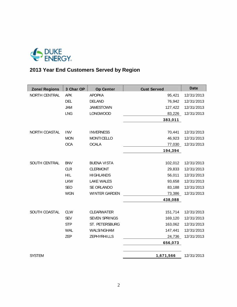
2013 Year End Customers Served by Region
Zone/Regions 3 Char OP Op Center Cust Served Date
NORTH CENTRAL APK APOPKA 95,421 12/31/2013
DEL DELAND 76,942 12/31/2013
JAM JAMESTOWN 127,422 12/31/2013
LNG LONGWOOD 83,226 12/31/2013
383,011
NORTH COASTAL INV INVERNESS 70,441 12/31/2013
MON MONTICELLO 46,923 12/31/2013
OCA OCALA 77,030 12/31/2013
194,394
SOUTH CENTRAL BNV BUENA VISTA 102,012 12/31/2013
CLR CLERMONT 29,833 12/31/2013
HIL HIGHLANDS 56,011 12/31/2013
LKW LAKE WALES 93,658 12/31/2013
SEO SE ORLANDO 83,188 12/31/2013
WGN WINTER GARDEN 73,386 12/31/2013
438,088
SOUTH COASTAL CLW CLEARWATER 151,714 12/31/2013
SEV SEVEN SPRINGS 169,120 12/31/2013
STP ST. PETERSBURG 163,062 12/31/2013
WAL WALSINGHAM 147,441 12/31/2013
ZEP ZEPHYRHILLS 24,736 12/31/2013
656,073
SYSTEM
1,671,566 12/31/2013
3
I. OVERALL RELIABILITY PERFORMANCE – 2013 (Rule 25-6.0455, F.A.C.)
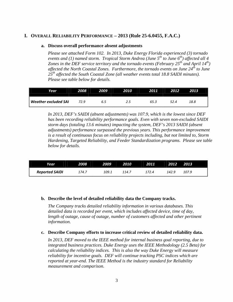
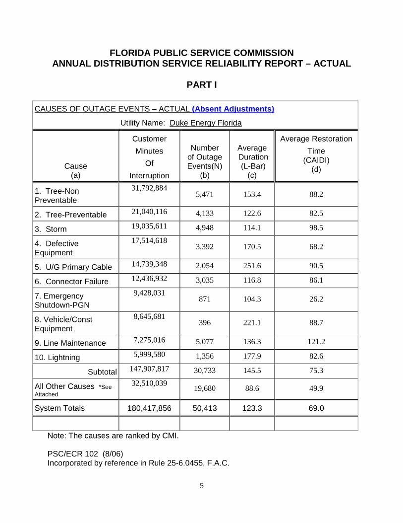
a. Discuss overall performance absent adjustments Please see attached Form 102. In 2013, Duke Energy Florida experienced (3) tornado events and (1) named storm. Tropical Storm Andrea (June 5th to June 6th) affected all 4 Zones in the DEF service territory and the tornado events (February 25th and April 14th) affected the North Coastal Zones. Furthermore, the tornado events on June 24th to June 25th affected the South Coastal Zone (all weather events total 18.8 SAIDI minutes). Please see table below for details.
In 2013, DEF’s SAIDI (absent adjustments) was 107.9, which is the lowest since DEF has been recording reliability performance goals. Even with seven non-excluded SAIDI storm days (totaling 13.6 minutes) impacting the system, DEF’s 2013 SAIDI (absent adjustments) performance surpassed the previous years. This performance improvement is a result of continuous focus on reliability projects including, but not limited to, Storm Hardening, Targeted Reliability, and Feeder Standardization programs. Please see table below for details.
b. Describe the level of detailed reliability data the Company tracks. The Company tracks detailed reliability information in various databases. This detailed data is recorded per event, which includes affected device, time of day, length of outage, cause of outage, number of customers affected and other pertinent information.
c. Describe Company efforts to increase critical review of detailed reliability data.
In 2013, DEF moved to the IEEE method for internal business goal reporting, due to integrated business practices. Duke Energy uses the IEEE Methodology (2.5 Beta) for calculating the reliability indices. This is also the way Duke Energy will measure reliability for incentive goals. DEF will continue tracking PSC indices which are reported at year-end. The IEEE Method is the industry standard for Reliability measurement and comparison.
Year 2008 2009 2010 2011 2012 2013
Weather excluded SAI 72.9 6.5 2.5 65.3 52.4 18.8
Year 2008 2009 2010 2011 2012 2013
Reported SAIDI 174.7 109.1 114.7 172.4 142.9 107.9
4
DEF continued the practice of auditing outage data to ensure accuracy and using Outage Management System Reconciliation (OMSr) as a platform which allows outage data to be captured in greater detail. DEF continued to utilize the Reliability Engagement Model that provides a consistent process and easy to use tools to evaluate individual outages with significant reliability impact on a daily basis. The Daily Reliability Exception Report is a daily report with key outage data at the operations center, region and system level. This report is intended to help focus the daily engagement efforts in reliability. The expectation is to focus on assessing the performance of the outage restoration effort on a real time basis and take the required actions to address all of the identified gaps. DEF continued to utilize the CEMI device report. The CEMI device report looks at devices that have gone out four times or more in the given year. This report is distributed to planning engineers, field personnel, and management for review. Funding is set aside for issues that are determined to need addressing immediately and long term capital projects are identified and submitted for approval for the following year. The CEMI premise database looks at CEMI outliers on a premise/meter level. This database will enable Duke Energy to identify the specific customers that are not solely affected by one consistently failing device and would therefore not be identified on the CEMI device report. In 2013, DEF began the implementation of a formal Outage Follow-Up Process. The purpose of this new initiative is to investigate significant outages identifying the primary root cause and implementing engineered solutions to mitigate any reoccurrence. The long term goal is to identify systemic improvements that will enhance a customer’s overall reliability experience.
d. Describe the process used by your company to identify and select the level of detailed reliability data. Customer feedback, benchmarking with other utilities, input from the FPSC, performance of assets, and trends are all considered when identifying the level of detailed reliability data.
e. Discuss adjustments i. Generation events – see pages 12 - 13.
ii. Transmission events – see page 14. iii. Distribution events – see page 17. iv. Extreme weather – see page 15.
f. Discuss adjusted performance.
For the 2013 adjusted performance results, please see pages 18 – 28.
5
FLORIDA PUBLIC SERVICE COMMISSION ANNUAL DISTRIBUTION SERVICE RELIABILITY REPORT – ACTUAL
PART I
CAUSES OF OUTAGE EVENTS – ACTUAL (Absent Adjustments)
Utility Name: Duke Energy Florida
Cause (a)
Customer Minutes
Of Interruption
Number
of Outage Events(N)
(b)
Average Duration (L-Bar)
(c)
Average Restoration Time
(CAIDI) (d)
1. Tree-Non Preventable
31,792,884 5,471 153.4 88.2
2. Tree-Preventable 21,040,116 4,133 122.6 82.5
3. Storm 19,035,611 4,948 114.1 98.5
4. Defective Equipment
17,514,618 3,392 170.5 68.2
5. U/G Primary Cable 14,739,348 2,054 251.6 90.5
6. Connector Failure 12,436,932 3,035 116.8 86.1
7. Emergency Shutdown-PGN
9,428,031 871 104.3 26.2
8. Vehicle/Const Equipment
8,645,681 396 221.1 88.7
9. Line Maintenance 7,275,016 5,077 136.3 121.2
10. Lightning 5,999,580 1,356 177.9 82.6
Subtotal 147,907,817 30,733 145.5 75.3
All Other Causes *See Attached
32,510,039 19,680 88.6 49.9
System Totals 180,417,856 50,413 123.3 69.0
Note: The causes are ranked by CMI. PSC/ECR 102 (8/06) Incorporated by reference in Rule 25-6.0455, F.A.C.
6
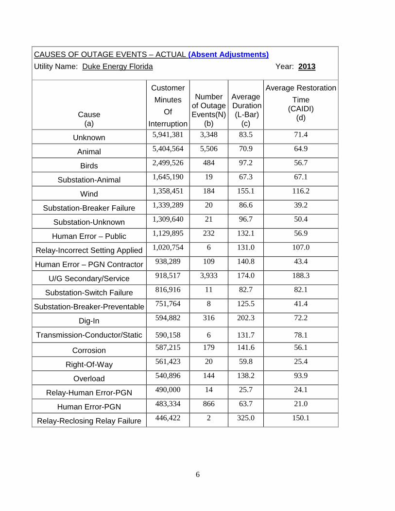
CAUSES OF OUTAGE EVENTS – ACTUAL (Absent Adjustments) Utility Name: Duke Energy Florida Year: 2013
Cause (a)
Customer Minutes
Of Interruption
Number
of Outage Events(N)
(b)
Average Duration (L-Bar)
(c)
Average Restoration Time
(CAIDI) (d)
Unknown 5,941,381 3,348 83.5 71.4
Animal 5,404,564 5,506 70.9 64.9
Birds 2,499,526 484 97.2 56.7
Substation-Animal 1,645,190 19 67.3 67.1
Wind 1,358,451 184 155.1 116.2
Substation-Breaker Failure 1,339,289 20 86.6 39.2
Substation-Unknown 1,309,640 21 96.7 50.4
Human Error – Public 1,129,895 232 132.1 56.9
Relay-Incorrect Setting Applied 1,020,754 6 131.0 107.0
Human Error – PGN Contractor 938,289 109 140.8 43.4
U/G Secondary/Service 918,517 3,933 174.0 188.3
Substation-Switch Failure 816,916 11 82.7 82.1
Substation-Breaker-Preventable 751,764 8 125.5 41.4
Dig-In 594,882 316 202.3 72.2
Transmission-Conductor/Static 590,158 6 131.7 78.1
Corrosion 587,215 179 141.6 56.1
Right-Of-Way 561,423 20 59.8 25.4
Overload 540,896 144 138.2 93.9
Relay-Human Error-PGN 490,000 14 25.7 24.1
Human Error-PGN 483,334 866 63.7 21.0
Relay-Reclosing Relay Failure 446,422 2 325.0 150.1
7
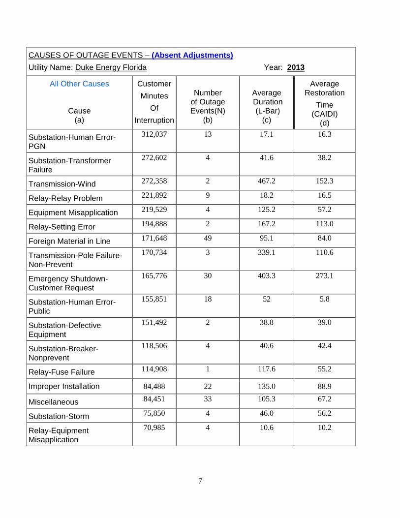
CAUSES OF OUTAGE EVENTS – (Absent Adjustments) Utility Name: Duke Energy Florida Year: 2013
All Other Causes
Cause (a)
Customer Minutes
Of Interruption
Number
of Outage Events(N)
(b)
Average Duration (L-Bar)
(c)
Average Restoration
Time (CAIDI)
(d)
Substation-Human Error-PGN
312,037 13 17.1 16.3
Substation-Transformer Failure
272,602 4 41.6 38.2
Transmission-Wind 272,358 2 467.2 152.3
Relay-Relay Problem 221,892 9 18.2 16.5
Equipment Misapplication 219,529 4 125.2 57.2
Relay-Setting Error 194,888 2 167.2 113.0
Foreign Material in Line 171,648 49 95.1 84.0
Transmission-Pole Failure- Non-Prevent
170,734 3 339.1 110.6
Emergency Shutdown-Customer Request
165,776 30 403.3 273.1
Substation-Human Error-Public
155,851 18 52 5.8
Substation-Defective Equipment
151,492 2 38.8 39.0
Substation-Breaker-Nonprevent
118,506 4 40.6 42.4
Relay-Fuse Failure 114,908 1 117.6 55.2
Improper Installation 84,488 22 135.0 88.9
Miscellaneous 84,451 33 105.3 67.2
Substation-Storm 75,850 4 46.0 56.2
Relay-Equipment Misapplication
70,985 4 10.6 10.2
8
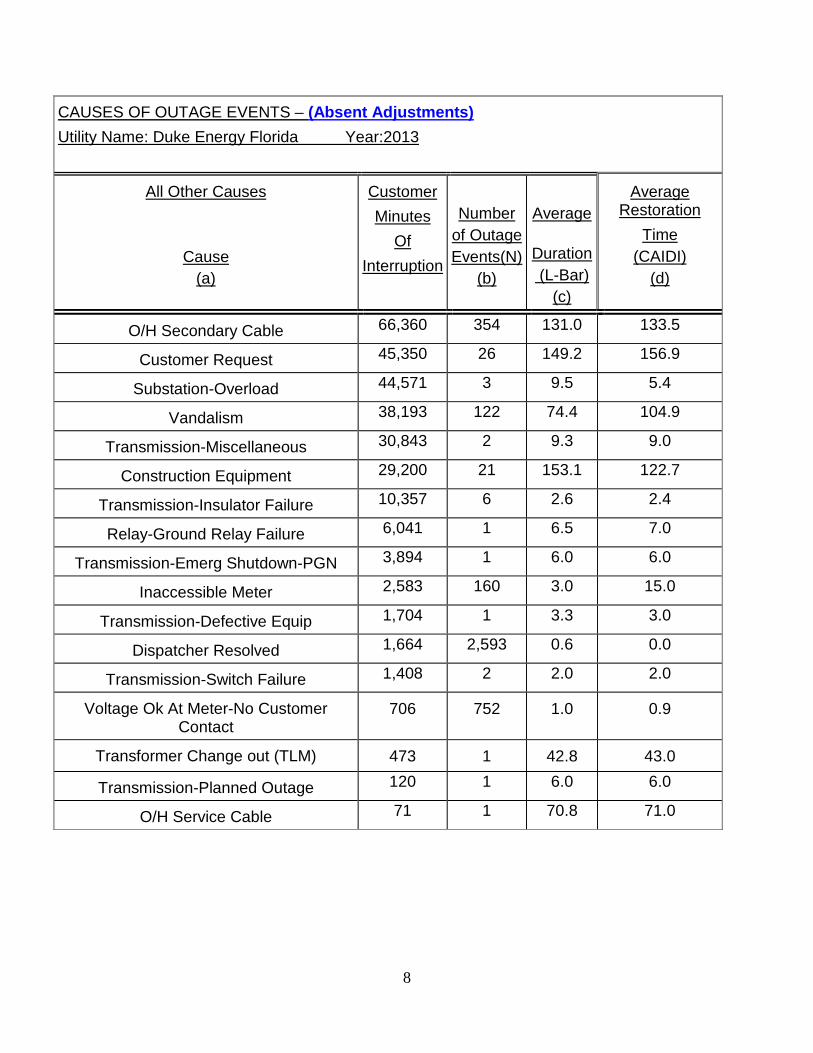
CAUSES OF OUTAGE EVENTS – (Absent Adjustments) Utility Name: Duke Energy Florida Year:2013
All Other Causes
Cause (a)
Customer Minutes
Of Interruption
Number
of Outage Events(N)
(b)
Average
Duration (L-Bar)
(c)
Average Restoration
Time (CAIDI)
(d)
O/H Secondary Cable 66,360 354 131.0 133.5
Customer Request 45,350 26 149.2 156.9
Substation-Overload 44,571 3 9.5 5.4
Vandalism 38,193 122 74.4 104.9
Transmission-Miscellaneous 30,843 2 9.3 9.0
Construction Equipment 29,200 21 153.1 122.7
Transmission-Insulator Failure 10,357 6 2.6 2.4
Relay-Ground Relay Failure 6,041 1 6.5 7.0
Transmission-Emerg Shutdown-PGN 3,894 1 6.0 6.0
Inaccessible Meter 2,583 160 3.0 15.0
Transmission-Defective Equip 1,704 1 3.3 3.0
Dispatcher Resolved 1,664 2,593 0.6 0.0
Transmission-Switch Failure 1,408 2 2.0 2.0
Voltage Ok At Meter-No Customer Contact
706 752 1.0 0.9
Transformer Change out (TLM) 473 1 42.8 43.0
Transmission-Planned Outage 120 1 6.0 6.0
O/H Service Cable 71 1 70.8 71.0
9
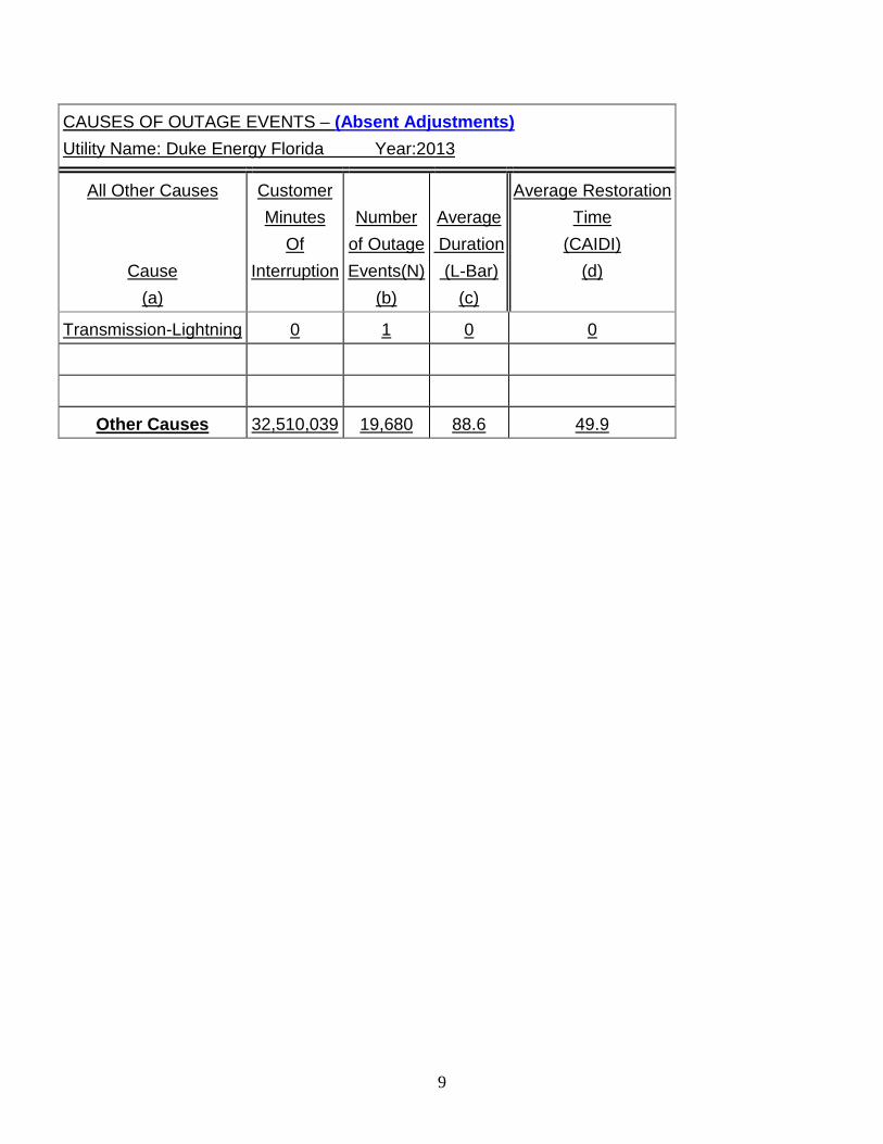
CAUSES OF OUTAGE EVENTS – (Absent Adjustments) Utility Name: Duke Energy Florida Year:2013
All Other Causes
Cause (a)
Customer Minutes
Of Interruption
Number
of Outage Events(N)
(b)
Average Duration (L-Bar)
(c)
Average Restoration Time
(CAIDI) (d)
Transmission-Lightning 0 1 0 0
Other Causes 32,510,039 19,680 88.6 49.9
10
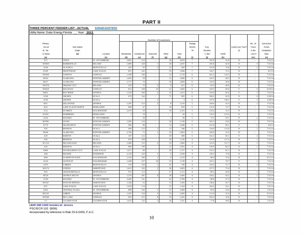
THREE PERCENT FEEDER LIST - ACTUAL (UNADJUSTED)Utility Name: Duke Energy Florida Year: 2013
Primary Outage No. of Corrective
Circuit Sub-station Events Avg Listed Last Year? Years Action
Id. No. Origin “N” Duration (l) in the Completion
or Name (b) Location Residential Commercial Industrial Other Total “L-Bar” CAIDI Last 5 Date
(a) (c) (d) (e) (f) (g) (h) (i) (j) (k) (m) (n)X71 VINOY ST. PETERSBURG 2,801 214 - 40 3,055 7 105.9 41.0 N - 7/22/13
W0904 BARBERVILLE DELAND 1,800 220 1 26 2,047 7 105.8 62.9 N 4 7/31/14
A144 ALACHUA MONTICELLO 447 93 5 21 566 7 125.0 72.8 N 2 7/31/14
K100 FROSTPROOF LAKE WALES 851 162 - 55 1,068 7 126.7 72.5 N - 8/1/13
W0408 CONWAY CONWAY 1,598 106 - 14 1,718 6 261.5 114.5 N - 7/31/14
M342 CLARCONA WINTER GARDEN 1,820 58 - 11 1,889 6 142.5 49.5 N - 7/31/14
M337 CLARCONA WINTER GARDEN 1,717 74 - 18 1,809 6 119.6 40.8 N - 7/31/14
W0378 ORANGE CITY DELAND 525 75 2 9 611 6 93.5 46.6 N - 7/31/14
W0629 HOLOPAW CONWAY 813 238 10 21 1,082 6 159.3 85.0 Y 3 9/19/13
M451 BAY RIDGE APOPKA 1,229 166 2 15 1,412 6 154.6 92.6 Y 1 7/31/14
A196 ARCHER OCALA 670 164 - 71 905 6 108.5 63.0 N 4 2/28/14
A195 ARCHER OCALA 1 - 2 - 3 6 147.6 138.1 Y 2 2/28/14
M31 ZELLWOOD APOPKA 1,287 213 2 8 1,510 5 144.0 41.4 N 1 7/31/14
K24 LAKE PLACID NORTH HIGHLANDS 868 67 - 24 959 5 132.9 72.7 N - 7/31/14
J112 STARKEY WALSINGHAM 2,010 59 - 34 2,103 5 116.6 32.4 N - 7/31/14
K3205 PEMBROKE HIGHLANDS 1 19 - - 20 5 170.2 213.4 N - 7/31/14
X144 MAXIMO ST. PETERSBURG - 29 - 1 30 5 73.2 29.1 N 2 7/31/14
M1096 OCOEE WINTER GARDEN 1,582 116 - 30 1,728 5 102.3 25.6 N - 7/31/14
K779 ISLESWORTH WINTER GARDEN 946 90 - 12 1,048 5 215.6 83.1 Y 1 9/4/13
A35 REDDICK OCALA 409 125 2 12 548 5 134.0 113.0 N 1 7/31/14
M346 CLARCONA WINTER GARDEN 2,766 71 1 25 2,863 5 169.9 35.5 N - 7/31/14
A39 MARTIN OCALA 347 112 - 29 488 5 162.2 82.1 Y 2 7/31/14
A36 REDDICK OCALA 870 238 - 18 1,126 4 135.0 117.4 N 1 7/31/14
W1110 DELAND EAST DELAND 1,484 151 2 23 1,660 4 123.6 111.7 N 1 7/31/14
A34 REDDICK OCALA 860 190 - 12 1,062 4 130.0 85.2 N 1 7/31/14
K966 INTERCESSION CITY LAKE WALES 1,617 90 - 50 1,757 4 153.3 81.1 N - 7/31/14
A48 HOLDER INVERNESS 2,129 163 1 6 2,299 4 139.3 75.8 N - 7/31/14
J684 ULMERTON WEST WALSINGHAM 2,103 200 1 6 2,310 4 98.9 75.6 N - 8/11/13
X120 GATEWAY WALSINGHAM 1,448 227 20 33 1,728 4 163.3 74.7 Y 1 7/31/14
A379 O BRIEN MONTICELLO 534 164 1 41 740 4 144.5 72.7 N 1 7/31/14
W0174 OVIEDO JAMESTOWN 1,612 163 2 26 1,803 4 127.5 72.4 N - 7/31/14
N35 CRAWFORDVILLE MONTICELLO 972 113 - 27 1,112 4 89.2 65.8 N 1 7/31/14
M720 APOPKA SOUTH APOPKA 1,276 287 9 28 1,600 4 128.2 63.2 N 1 7/31/14
X149 MAXIMO ST. PETERSBURG 2,485 161 - 62 2,708 4 88.8 57.2 N - 7/31/14
W0187 WINTER SPRINGS JAMESTOWN 1,328 53 - 13 1,394 4 138.6 55.7 N - 7/31/14
K57 LAKE WALES LAKE WALES 1,028 114 - 22 1,164 4 164.3 54.1 N - 7/31/14
X265 CENTRAL PLAZA ST. PETERSBURG 898 142 1 27 1,068 4 92.9 53.6 N - 7/31/14
M1520 LISBON APOPKA 1,447 134 4 15 1,600 4 113.0 52.9 N - 9/13/13
W0368 SKY LAKE CONWAY 823 411 8 23 1,265 4 204.3 52.6 N 1 7/31/14
C7 CLEARWATER CLEARWATER 1,023 121 3 20 1,167 4 77.8 49.9 N - 7/31/14
LBAR AND CAIDI Includes all devices.PSC/ECR 102 (8/06)Incorporated by reference in Rule 25-6.0455, F.A.C.
PART II
Number of Customers
11
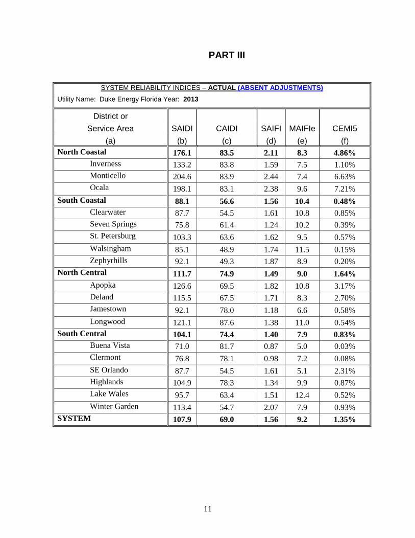
PART III
SYSTEM RELIABILITY INDICES – ACTUAL (ABSENT ADJUSTMENTS)
Utility Name: Duke Energy Florida Year: 2013
District or
Service Area SAIDI CAIDI SAIFI MAIFIe CEMI5
(a) (b) (c) (d) (e) (f)
North Coastal 176.1 83.5 2.11 8.3 4.86%
Inverness 133.2 83.8 1.59 7.5 1.10%
Monticello 204.6 83.9 2.44 7.4 6.63%
Ocala 198.1 83.1 2.38 9.6 7.21%
South Coastal 88.1 56.6 1.56 10.4 0.48%
Clearwater 87.7 54.5 1.61 10.8 0.85%
Seven Springs 75.8 61.4 1.24 10.2 0.39%
St. Petersburg 103.3 63.6 1.62 9.5 0.57%
Walsingham 85.1 48.9 1.74 11.5 0.15%
Zephyrhills 92.1 49.3 1.87 8.9 0.20%
North Central 111.7 74.9 1.49 9.0 1.64%
Apopka 126.6 69.5 1.82 10.8 3.17%
Deland 115.5 67.5 1.71 8.3 2.70%
Jamestown 92.1 78.0 1.18 6.6 0.58%
Longwood 121.1 87.6 1.38 11.0 0.54%
South Central 104.1 74.4 1.40 7.9 0.83%
Buena Vista 71.0 81.7 0.87 5.0 0.03%
Clermont 76.8 78.1 0.98 7.2 0.08%
SE Orlando 87.7 54.5 1.61 5.1 2.31%
Highlands 104.9 78.3 1.34 9.9 0.87%
Lake Wales 95.7 63.4 1.51 12.4 0.52%
Winter Garden 113.4 54.7 2.07 7.9 0.93%
SYSTEM 107.9 69.0 1.56 9.2 1.35%
12
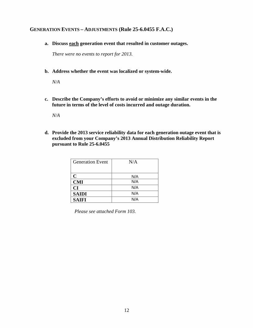
GENERATION EVENTS – ADJUSTMENTS (Rule 25-6.0455 F.A.C.)
a. Discuss each generation event that resulted in customer outages.
There were no events to report for 2013. b. Address whether the event was localized or system-wide.
N/A c. Describe the Company’s efforts to avoid or minimize any similar events in the
future in terms of the level of costs incurred and outage duration.
N/A d. Provide the 2013 service reliability data for each generation outage event that is
excluded from your Company’s 2013 Annual Distribution Reliability Report pursuant to Rule 25-6.0455
Generation Event N/A
C N/A CMI N/A CI N/A SAIDI N/A SAIFI N/A
Please see attached Form 103.
13
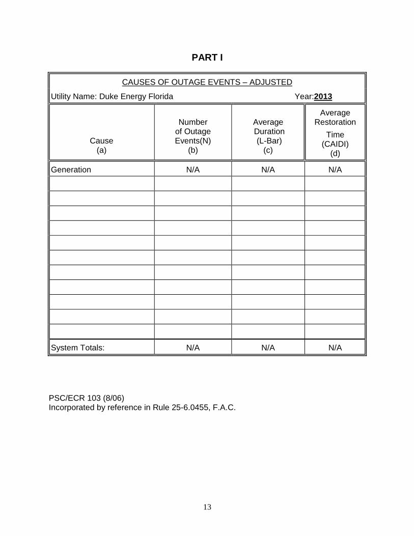
PART I
CAUSES OF OUTAGE EVENTS – ADJUSTED
Utility Name: Duke Energy Florida Year:2013
Cause (a)
Number
of Outage Events(N)
(b)
Average Duration (L-Bar)
(c)
Average Restoration
Time (CAIDI)
(d)
Generation N/A N/A N/A
System Totals: N/A N/A N/A PSC/ECR 103 (8/06) Incorporated by reference in Rule 25-6.0455, F.A.C.
14
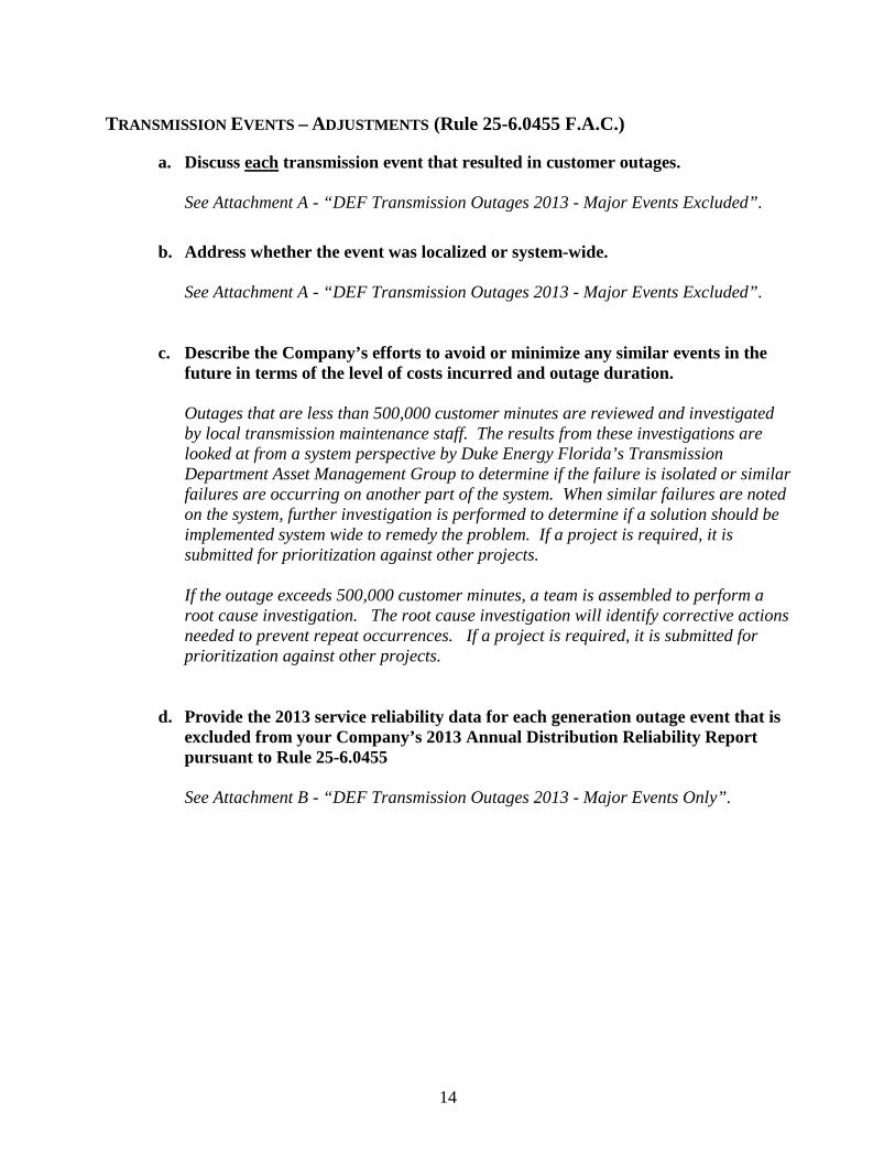
TRANSMISSION EVENTS – ADJUSTMENTS (Rule 25-6.0455 F.A.C.)
a. Discuss each transmission event that resulted in customer outages.
See Attachment A - “DEF Transmission Outages 2013 - Major Events Excluded”. b. Address whether the event was localized or system-wide.
See Attachment A - “DEF Transmission Outages 2013 - Major Events Excluded”.
c. Describe the Company’s efforts to avoid or minimize any similar events in the
future in terms of the level of costs incurred and outage duration.
Outages that are less than 500,000 customer minutes are reviewed and investigated by local transmission maintenance staff. The results from these investigations are looked at from a system perspective by Duke Energy Florida’s Transmission Department Asset Management Group to determine if the failure is isolated or similar failures are occurring on another part of the system. When similar failures are noted on the system, further investigation is performed to determine if a solution should be implemented system wide to remedy the problem. If a project is required, it is submitted for prioritization against other projects. If the outage exceeds 500,000 customer minutes, a team is assembled to perform a root cause investigation. The root cause investigation will identify corrective actions needed to prevent repeat occurrences. If a project is required, it is submitted for prioritization against other projects.
d. Provide the 2013 service reliability data for each generation outage event that is
excluded from your Company’s 2013 Annual Distribution Reliability Report pursuant to Rule 25-6.0455 See Attachment B - “DEF Transmission Outages 2013 - Major Events Only”.
15
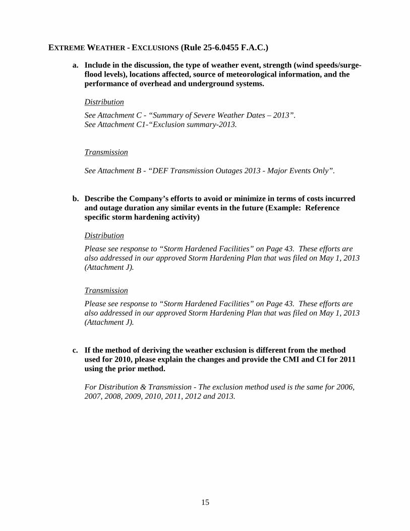
EXTREME WEATHER - EXCLUSIONS (Rule 25-6.0455 F.A.C.)
a. Include in the discussion, the type of weather event, strength (wind speeds/surge-flood levels), locations affected, source of meteorological information, and the performance of overhead and underground systems.
Distribution See Attachment C - “Summary of Severe Weather Dates – 2013”. See Attachment C1-“Exclusion summary-2013. Transmission See Attachment B - “DEF Transmission Outages 2013 - Major Events Only”.
b. Describe the Company’s efforts to avoid or minimize in terms of costs incurred
and outage duration any similar events in the future (Example: Reference specific storm hardening activity)
Distribution Please see response to “Storm Hardened Facilities” on Page 43. These efforts are also addressed in our approved Storm Hardening Plan that was filed on May 1, 2013 (Attachment J).
Transmission
Please see response to “Storm Hardened Facilities” on Page 43. These efforts are also addressed in our approved Storm Hardening Plan that was filed on May 1, 2013 (Attachment J).
c. If the method of deriving the weather exclusion is different from the method used for 2010, please explain the changes and provide the CMI and CI for 2011 using the prior method.
For Distribution & Transmission - The exclusion method used is the same for 2006, 2007, 2008, 2009, 2010, 2011, 2012 and 2013.
16
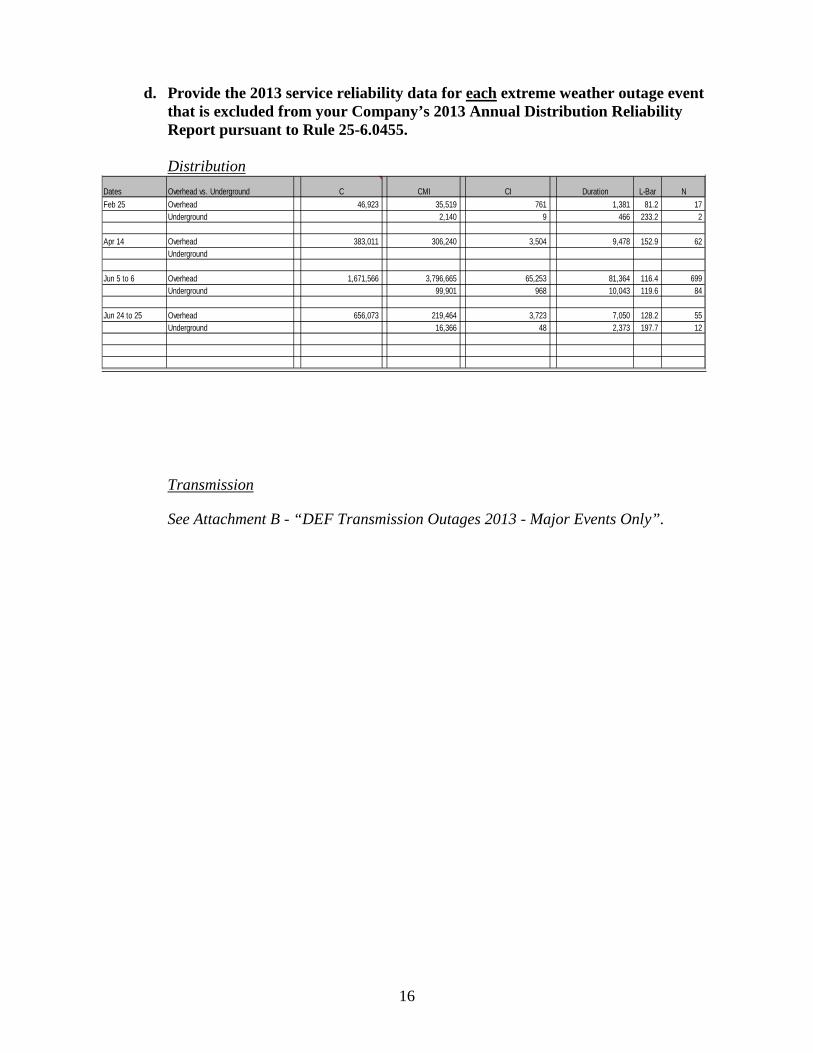
d. Provide the 2013 service reliability data for each extreme weather outage event that is excluded from your Company’s 2013 Annual Distribution Reliability Report pursuant to Rule 25-6.0455.
Distribution
Transmission
See Attachment B - “DEF Transmission Outages 2013 - Major Events Only”.
Dates Overhead vs. Underground C CMI CI Duration L-Bar NFeb 25 Overhead 46,923 35,519 761 1,381 81.2 17
Underground 2,140 9 466 233.2 2
Apr 14 Overhead 383,011 306,240 3,504 9,478 152.9 62 Underground
Jun 5 to 6 Overhead 1,671,566 3,796,665 65,253 81,364 116.4 699 Underground 99,901 968 10,043 119.6 84
Jun 24 to 25 Overhead 656,073 219,464 3,723 7,050 128.2 55 Underground 16,366 48 2,373 197.7 12
17
OTHER DISTRIBUTION – ADJUSTMENTS (Rule 25-6.0455, F.A.C.)
a. Discuss the causation of each type of distribution event that resulted in customer complaints.
Since Duke Energy Florida has not taken other causations as exclusions for any events in 2013, DEF has no information to report in this section.
b. Describe the Company’s efforts to avoid or minimize any similar events in the
future in terms of the level of costs incurred and outage duration.
Since Duke Energy Florida has not taken other causations as exclusions for any events in 2013, DEF has no information to report in this section.
c. Provide the 2013 service reliability data for each distribution outage event that is
excluded from your Company’s 2013 Annual Distribution Reliability Report pursuant to Rule 25-6.0455
i. A table ii. Electronic file iii. Causation, Date, CMI, CI Total Repair Cost, etc.
Since Duke Energy Florida has not taken other causations as exclusions for any events in 2013, DEF has no information to report in this section.
18
2013 ADJUSTED RELIABILITY (Rule 25-6.0455, F.A.C.)
Duke Energy Florida’s (DEF) 2013 annual adjusted SAIDI was very similar to the 2010 and 2011 SAIDI metrics. However, this was an increase over 2012, which was observed as the lowest SAIDI since DEF has been recording reliability performance goals. The primary driver in 2013 is that storm activity was more frequent and severe than the 3 year average causing higher outage volume to occur in the DEF service territory. The first extreme weather event was on March 24th, with wind gusts in excess of 62 mph and severe thunderstorms throughout the DEF service territory. This extreme weather day was not excludable and contributed nearly 6 SAIDI minutes in 2013. Furthermore, 6 other days (April 30th, July 4th, August 17th, August 21st, August 22nd, and September 15th) of extreme weather accounted for 7.6 SAIDI minutes. Removal of these SAIDI minutes, totaling 13.6 SAIDI would result in a SAIDI comparable to the year 2012. Moreover, in the North Coastal Zone these 7 extreme weather days totaled 18.2 Zone SAIDI minutes. When removed, the North Coastal Zone results in SAIDI minutes that would be lower than the 2012 year. Our reliability strategy is to improve performance by outage prevention. The on-going goal is the elimination of future outages at a specific location for a specific reason. To improve reliability, the utility must control faults. In 2013, DEF implemented the Outage Follow Up (OFU) process to increase the focus on the primary root cause of significant outage events and provide actionable data about controlling faults. The OFU process entails investigating significant outages in order to identify the primary root cause and implement engineered solutions to mitigate the reoccurrence of an event of that nature. The Primary Root Cause is the root cause for which the utility can take action to correct in a timely and economical manner. Most Primary Root Causes are actionable. Many initiating causes (e.g. lightning, traffic accident) are not actionable. Elimination of faults on the distribution system is the most cost effective reliability improvement strategy. Fault removal results in the improvement of all properly normalized reliability measures (e.g. SAIDI, SAIFI, and MAIFI). OFU is the key to determining why faults occur, and what can be done to eliminate them. OFU is a standard, institutionalized process and a major part of the reliability culture. All Duke Energy reliability programs, from construction audits to distribution storm hardening are based on information derived from the Outage Follow Up process. The long term goal is to identify systemic improvements that will enhance customers’ overall reliability experience. In 2013 there was an increase in severe storms that quickly materialized into major weather events which adversely impacted DEF’s SAIDI. These events were not excludable under PSC guidelines. These weather patterns were absent in 2012, but were experienced in the years prior to 2012.
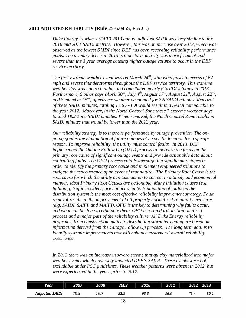
Year 2007 2008 2009 2010 2011 2012 2013
Adjusted SAIDI 78.3 75.7 82.8 93.3 86.9 73.4 89.1
19
a. Causes of outages events – see attached forms. i. 5-yr patterns/trends in outage causation for each of the top 10 causes of
outage events, including the frequency, duration, restoration time, cost incurred to restore service, remediation programs and costs.
• See Attachment D - “5 yr. Trend by Cause Code” Spreadsheet for 2009 - 2013.
ii. The process used to identify and select the actions to improve the performance in each of the top 10 causes of outages. DEF prioritizes the reliability improvement action plan by balancing historical and current year performance. System devices are evaluated based on the number of interruptions, customers interrupted (CI), and customer minutes of interruption (CMI). In addition, current year performance is monitored monthly to identify emergent and seasonal issues including load balancing for cold weather and the need for foot patrols of devices experiencing multiple interruptions.
iii. 2013 activities and budget levels addressing each of the 10 causes of service outage.
• See Attachment E - “2013 Program Budget” Spreadsheet.
b. Three percent Feeder list i. Identify whether any feeders appear on the 3% listing more than once
within a consecutive 5-yr. period and any actions implemented to improve feeder performance. Feeder A195:
• A195 is an express industrial feeder to a foundry furnace that only runs intermittently. Outage impacts to industrial customers are minimal and do not generate complaints. One residential customer exists on the feeder due to inability to serve from adjacent feeder.
• Switches added in early 2014 to isolate the least reliable section of feeder and tie customer to adjacent feeder A196. Historically, this was not possible due to large furnace load that would cause unacceptable flicker to other customers. Foundry recently changed to a smaller furnace that has much less flicker and can be sourced on adjacent feeder without complaints.
• This is 1/0A feeder through easements with limited ability to control private property tree canopy effects which cause the vast majority of outages.
• DEF Infrared Red scanned in June 2013, No issues found after completing Infrared Red scanning. DEF will continue to Infrared Red scan main feeder A195 in June/July 2014
Feeder A196:
20
• Private property tree canopy over our lines in sections are severe and are the source of the vast majority of the outage causes. This is not due to the lack of tree trimming, but the configuration of the circuit related to limited public R/W and adjacent wooded acreage.
• Approximately 272 customers (the Town of Bronson) have been part of an Auto Transfer Scheme (ATS) on this feeder for over 20 years. For feeder breaker outages of A196 these customers are automatically transferred to Williston Substation feeder A124 and do not experience an outage. This ATS was installed to improve the performance to the county seat of Levy County due to the chronic performance problems on this feeder. Our ability to minimize the tree outages has been a constant battle for many years.
• 2013 Tree Trimming Completed A196 in 2013: Trimmed 100% of the feeder (3.78 miles) and laterals (74.77 miles) this year and are complete.
• DEF Infrared Red scanned in June 2013, No issues found after completing Infrared Red scanning. DEF will continue to Infrared Red scan main feeder A196 in June/July 2014
• In early 2014, DEF completed installing 3 sets of switches that would allow for emergency pick-up of some A196 loads on A195 if necessary during lengthy outages. Only the town of Archer (430 customers) could be transferred of the 900 total on A196. These switches will also enable similar benefits to A195 customers as noted above.
Feeder A39:
• DEF Infrared Red scanned in June 2013. No issues found after completing Infrared Red scanning. DEF will continue to Infrared Red scan main feeder A39 in June 2014.
• This feeder has a large exposure to private property tree canopy and wooded acreage that chronically impacts its reliability. This feeder is similar to the other 9 feeders in our Reddick service territory. They have all been chronically frequent entries on the worst performing feeder list since its inception.
• A 2013 outage investigation identified branch line recloser that was poorly coordinated with the feeder breaker. The recloser has been replaced with a fuse that will prevent future feeder breaker outages.
• Further improvements to fault isolation from the feeder breaker on this branchline will be made in 2014 by installing a set of fuses at the substation in conjunction with a new construction project.
• In 2013, DEF completed recloser maintenance targets to confirm protective device coordination that ensures proper fault isolation to the fewest possible customers.
Feeder K779:
• DEF will Infrared Red scan main feeder K779 in June 2014
21
• Outages are mostly attributed to Storm and Tree related issues. This feeder resides in the downtown Windermere area which is heavily canopied and backlotted.
• PQRI conducted an Outage Follow up analysis at the end of 2013 to address CEMI premises. Corrective action are in the process of being inputted and will be addressed.
Feeder M451:
• Long rural radial feeder from Bay Ridge substation providing service to the north east area of Plymouth Sorrento (SR 46- 56.9 total miles).
• 2013 Outages (3) with high CMI are attributed to tree no preventable (2) and tree preventable (1) issues. Because of this, lateral lines were trimmed to the end of 2013, and feeder back bone will be tree trimmed during the 1st quarter of 2014.
• DEF developed a Storm Hardening project to be implemented on 2014. We will re-conductor 11,200 ft. of 1/0 conductor with 795 conductor, creating another source to feed-transfer load in case of outages, and reducing the radial exposure.
• DEF will Infrared Red scan main feeder M451 in June 2014 Feeder X120:
• X120 had 3 breaker level outages in 2013 which is why it is still on the list. One was due to a broken A Phase insulator, and the other two were due to pole fires.
• During a two week time frame in January and February of 2013, Pinellas County experienced at least 22 pole fires, some of which resulted in breaker level outages. A specific set of environmental factors seem to cause instances of pole fires in this part of the zone, and 2013 had more days like this than usual. During most years, pole fires rarely happen. Prime conditions for pole fires occur during periods of high pollen, salt spray, fog and sparse rain to cleanse the insulators.
• In response to this problem, DEF upgraded its construction standards to 35KV insulation in targeted areas of South Coastal zone in 2010. All new and replaced facilities are insulated to 35KV.
• DEF will Infrared Red scan Gateway X120 in June 2014 and perform a CEMI find and fix on the feeder in 2014.
Feeder K1104:
• DEF will Infrared Red scan this feeder in June 2014.
• One major outage of 186,581 CMI out of 222,737 CMI total is why it’s on the list for 2013. The outage was attributed to car hitting a pole.
• This feeder is generally quiet but is rather long for an urban environment. Situated in the Horizon West residential area which is the #1 URD growth area in South Central Zone.
22
• Future LGF facilities may change this feeder’s configuration down the road to mitigate its exposure. Expected completion in the next 2-3 years.
Feeder W0629:
• Very rural feeder. Long drive from South East Operation Center for restoration efforts. Very susceptible to storm exposure.
• The 3rd/4th quarter patrol of W-629 was done for items that needed attention. Work request were generated and identified items have been repaired/replaced. (Several Pole replacements, Cross-arms, few insulators that look suspicious, lightning arrestors, etc.) All this work was completed toward the end of the 4th quarter by South East Orlando Operations.
• All arresters on the PRECO 14 +/- mile section, were inspected and replaced, as well as ground testing was performed. Work was completed by the end of January 2014.
• W-629 is to have tree trimming started the first of 2014.
• (3) Cooper VWE recloser are scheduled to be replaced with G&W Viper Reclosers. These reclosers will provide more functionality and fault analysis capabilities. The units will be installed by the end of February and DSCADA communication packages will be incorporated into them by the end of June 2014.
• Multiyear target to rebuild 6 mile section of line to higher 25 kV spec has been submitted. This design will include taller poles and a static wire construction.
• W0629 was Infrared Red scanned in June 2013The scan found source side switch blades heating for the top and bottom phases. Corrected and replaced in field in September 2013.
• Over the last 3 years DEF has reconductored 30,000 plus feet of smaller wire to 336. This reconductor will has added bigger more robust cable which is more durable, eliminate spans with multiple splices, and increases our ability to add future load. There is also an additional 42,000 ft. that is in the plan to be reconductored and is part of our 3 year storm hardening plan that is being submitted.
• See attached form on Page 27.
ii. The process used to identify and select the actions to improve the performance of feeders in the 3% feeder list, if any. DEF prioritizes the reliability improvement action plan for the 3% Feeder List by balancing historical and current year performance. Feeders are evaluated based on the number of interruptions, customers interrupted (CI), and customer minutes of interruption (CMI). In addition, current year performance is monitored monthly to identify emergent and seasonal issues including load balancing for cold weather and the need for foot patrols of feeders experiencing multiple interruptions.

23
iii. 2014 activities and budget levels directed at improving feeder
performance. Feeders are prioritized for maintenance and replacement work based on several criteria including customer minutes of interruption (CMI), number of interruptions, interruption cause code, and CEMI repeat outage performance. This process results in a work plan targeted at feeders and devices having the greatest impact on reliability indices and customer satisfaction. This process has resulted in consistent and sustained reliability performance. The 3% feeder list is based solely on number of interruptions and does not take into consideration any of the additional criteria above. While all feeders on the 3% feeder list are patrolled for corrective action, the possibility exists that they could appear on the list more than once due to their relative impact on system reliability indices. For the 2014 budget levels, please see Attachment E - “2014 Program Budget” Spreadsheet.
c. Regional Reliability Indices – see attached forms.
i. 5-Yr. patterns/trends in each regions reliability for each index and on any overall basis.
• See Attachment F - “5 yr. Sum by Region” Spreadsheet.
ii. The process used to identify and select actions to improve the regional reliability trends.
• Regional reliability trends are tracked to ensure alignment with the system level goals they support. Specific device level improvements are measured and prioritized at a system level to ensure maximum benefit for resources expended.
iii. Discuss any 2014 projected activities and budget levels directed at improving regional reliability performance.
• See Attachment E - “2014 Program Budget” Spreadsheet. Regional reliability trends are tracked to ensure alignment with the system level goals they support. Specific device level improvements are measured and prioritized at a system level to ensure maximum benefit for resources expended.
• In 2013, DEF has implemented the Outage Follow-Up process. The OFU process entails investigating significant outages in order to identify the primary root cause and implement engineered solutions to mitigate the reoccurrence of an event of that nature. The long term goal is to identify systemic improvements that will enhance a customer’s overall reliability experience. DEF has completed multiple follow up projects in strengthening the target locations where the primary root cause was

24
identified and corrected in order to mitigate any future outage events at that location.
25
FLORIDA PUBLIC SERVICE COMMISSION
ANNUAL DISTRIBUTION SERVICE RELIABILITY REPORT – ADJUSTED
PART I
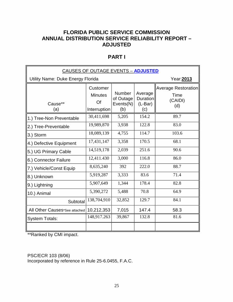
CAUSES OF OUTAGE EVENTS – ADJUSTED
Utility Name: Duke Energy Florida Year:2013
Cause** (a)
Customer Minutes
Of Interruption
Number
of Outage Events(N)
(b)
Average Duration (L-Bar)
(c)
Average Restoration Time
(CAIDI) (d)
1.) Tree-Non Preventable 30,411,698 5,205 154.2 89.7
2.) Tree-Preventable 19,989,870 3,938 122.8 83.0
3.) Storm 18,089,139 4,755 114.7 103.6
4.) Defective Equipment 17,431,147 3,358 170.5 68.1
5.) UG Primary Cable 14,519,178 2,039 251.6 90.6
6.) Connector Failure 12,411.430 3,000 116.8 86.0
7.) Vehicle/Const Equip 8,635,240 392 222.0 88.7
8.) Unknown 5,919,287 3,333 83.6 71.4
9.) Lightning 5,907,649 1,344 178.4 82.8
10.) Animal 5,390,272 5,488 70.8 64.9
Subtotal 138,704,910 32,852 129.7 84.1
All Other Causes*See attached 10,212,353 7,015 147.4 58.3
System Totals: 148,917.263 39,867 132.8 81.6
**Ranked by CMI impact. PSC/ECR 103 (8/06) Incorporated by reference in Rule 25-6.0455, F.A.C.
26
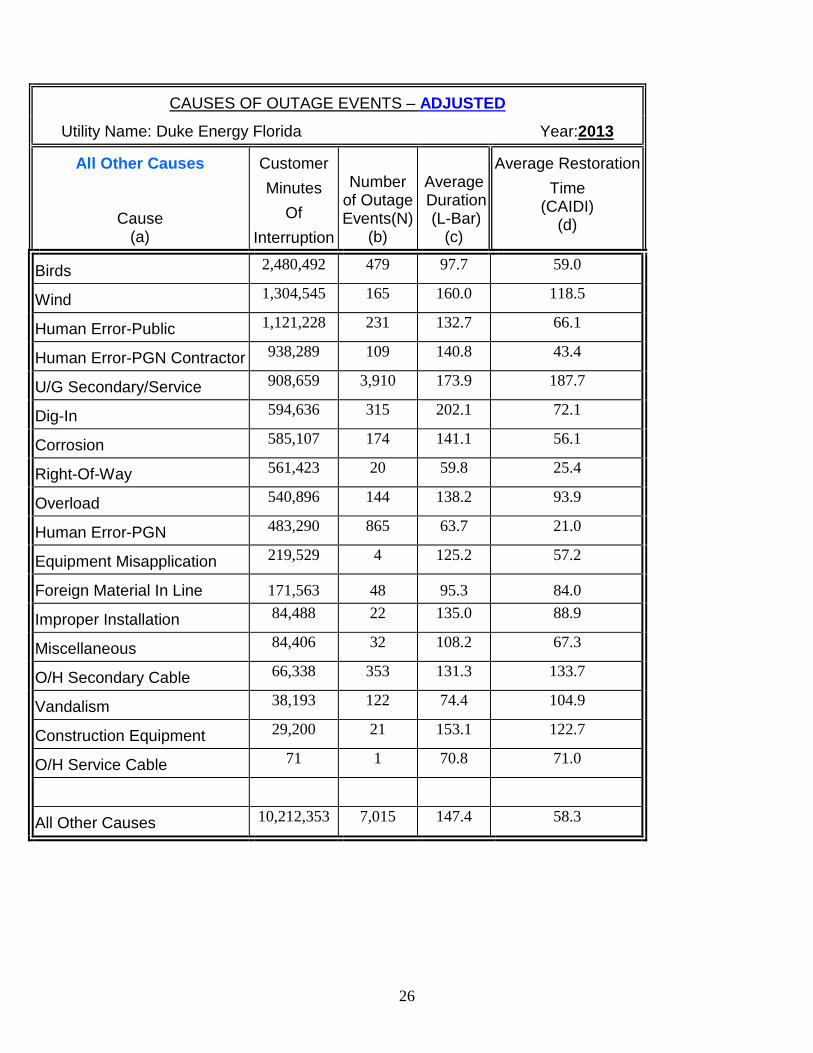
CAUSES OF OUTAGE EVENTS – ADJUSTED
Utility Name: Duke Energy Florida Year:2013
All Other Causes
Cause (a)
Customer Minutes
Of Interruption
Number
of Outage Events(N)
(b)
Average Duration (L-Bar)
(c)
Average Restoration Time
(CAIDI) (d)
Birds 2,480,492 479 97.7 59.0
Wind 1,304,545 165 160.0 118.5
Human Error-Public 1,121,228 231 132.7 66.1
Human Error-PGN Contractor 938,289 109 140.8 43.4
U/G Secondary/Service 908,659 3,910 173.9 187.7
Dig-In 594,636 315 202.1 72.1
Corrosion 585,107 174 141.1 56.1
Right-Of-Way 561,423 20 59.8 25.4
Overload 540,896 144 138.2 93.9
Human Error-PGN 483,290 865 63.7 21.0
Equipment Misapplication 219,529 4 125.2 57.2
Foreign Material In Line 171,563 48 95.3 84.0
Improper Installation 84,488 22 135.0 88.9
Miscellaneous 84,406 32 108.2 67.3
O/H Secondary Cable 66,338 353 131.3 133.7
Vandalism 38,193 122 74.4 104.9
Construction Equipment 29,200 21 153.1 122.7
O/H Service Cable 71 1 70.8 71.0
All Other Causes 10,212,353 7,015 147.4 58.3
27
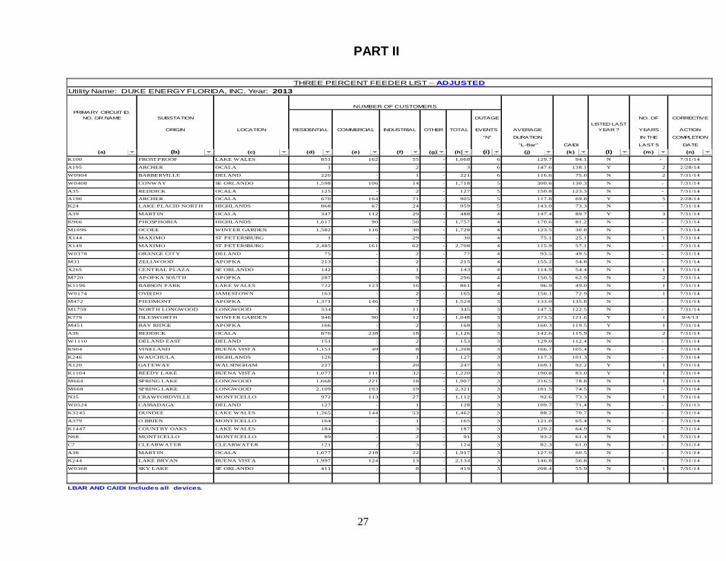
PRIMARY CIRCUIT ID. NO. OR NAME SUBSTATION OUTAGE NO. OF CORRECTIVE
ORIGIN LOCATION RESIDENTIAL COMMERCIAL INDUSTRIAL OTHER TOTAL EVENTS AVERAGELISTED LAST
YEAR ? YEARS ACTION
“N” DURATION IN THE COMPLETION
“L-Bar” CAIDI LAST 5 DATE
(a) (b) (c) (d) (e) (f) (g) (h) (i) (j) (k) (I) (m) (n)K100 FROSTPROOF LAKE WALES 851 162 55 - 1,068 6 129.7 94.1 N - 7/31/14
A195 ARCHER OCALA 1 - 2 - 3 6 147.6 138.1 Y 2 2/28/14
W0904 BARBERVILLE DELAND 220 - 1 - 221 6 116.6 75.0 N 2 7/31/14
W0408 CONWAY SE ORLANDO 1,598 106 14 - 1,718 5 300.6 130.3 N - 7/31/14
A35 REDDICK OCALA 125 - 2 - 127 5 150.8 123.3 N - 7/31/14
A196 ARCHER OCALA 670 164 71 - 905 5 117.8 69.8 Y 5 2/28/14
K24 LAKE PLACID NORTH HIGHLANDS 868 67 24 - 959 5 143.0 73.3 N - 7/31/14
A39 MARTIN OCALA 347 112 29 - 488 4 147.4 89.7 Y 3 7/31/14
K966 PHOSPHORIA HIGHLANDS 1,617 90 50 - 1,757 4 170.6 81.2 N - 7/31/14
M1096 OCOEE WINTER GARDEN 1,582 116 30 - 1,728 4 123.5 30.8 N - 7/31/14
X144 MAXIMO ST PETERSBURG 1 - 29 - 30 4 75.1 25.1 N 1 7/31/14
X149 MAXIMO ST PETERSBURG 2,485 161 62 - 2,708 4 115.9 57.1 N - 7/31/14
W0378 ORANGE CITY DELAND 75 - 2 - 77 4 93.5 49.5 N - 7/31/14
M31 ZELLWOOD APOPKA 213 - 2 - 215 4 155.2 54.8 N - 7/31/14
X265 CENTRAL PLAZA SE ORLANDO 142 - 1 - 143 4 114.9 54.4 N 1 7/31/14
M720 APOPKA SOUTH APOPKA 287 - 9 - 296 4 150.5 62.9 N 2 7/31/14
K1196 BABSON PARK LAKE WALES 722 123 16 - 861 4 96.9 49.0 N 1 7/31/14
W0174 OVIEDO JAMESTOWN 163 - 2 - 165 4 156.1 72.9 N 1 7/31/14
M472 PIEDMONT APOPKA 1,371 146 7 - 1,524 3 133.0 135.8 N - 7/31/14
M1758 NORTH LONGWOOD LONGWOOD 334 - 11 - 345 3 147.5 122.5 N - 7/31/14
K779 ISLESWORTH WINTER GARDEN 946 90 12 - 1,048 3 273.5 121.6 Y 1 9/4/13
M451 BAY RIDGE APOPKA 166 - 2 - 168 3 160.3 119.5 Y 1 7/31/14
A36 REDDICK OCALA 870 238 18 - 1,126 3 142.6 115.9 N 2 7/31/14
W1110 DELAND EAST DELAND 151 - 2 - 153 3 129.0 112.4 N - 7/31/14
K904 VINELAND BUENA VISTA 1,151 49 8 - 1,208 3 166.7 105.4 N - 7/31/14
K246 WAUCHULA HIGHLANDS 126 - 1 - 127 3 117.3 101.3 N - 7/31/14
X120 GATEWAY WALSINGHAM 227 - 20 - 247 3 169.1 92.2 Y 1 7/31/14
K1104 REEDY LAKE BUENA VISTA 1,077 111 32 - 1,220 3 190.8 83.0 Y 1 7/31/14
M664 SPRING LAKE LONGWOOD 1,668 221 18 - 1,907 3 216.5 78.8 N 1 7/31/14
M668 SPRING LAKE LONGWOOD 2,109 193 19 - 2,321 3 181.5 74.5 N - 7/31/14
N35 CRAWFORDVILLE MONTICELLO 972 113 27 - 1,112 3 92.6 73.3 N 1 7/31/14
W0524 CASSADAGA DELAND 127 - 1 - 128 3 109.7 71.4 N - 7/31/13
K3245 DUNDEE LAKE WALES 1,265 144 53 - 1,462 3 88.2 70.7 N - 7/31/14
A379 O BRIEN MONTICELLO 164 - 1 - 165 3 121.0 65.4 N - 7/31/14
K1447 COUNTRY OAKS LAKE WALES 184 - 3 - 187 3 129.2 64.9 N - 7/31/14
N68 MONTICELLO MONTICELLO 89 - 2 - 91 3 93.2 61.4 N 1 7/31/14
C7 CLEARWATER CLEARWATER 121 - 3 - 124 3 82.3 61.0 N - 7/31/14
A38 MARTIN OCALA 1,677 218 22 - 1,917 3 127.9 60.5 N - 7/31/14
K244 LAKE BRYAN BUENA VISTA 1,997 124 13 - 2,134 3 146.8 56.8 N - 7/31/14
W0368 SKY LAKE SE ORLANDO 411 - 8 - 419 3 208.4 55.9 N 1 7/31/14
LBAR AND CAIDI Includes all devices.
THREE PERCENT FEEDER LIST – ADJUSTEDUtility Name: DUKE ENERGY FLORIDA, INC. Year: 2013
NUMBER OF CUSTOMERS
PART II
28
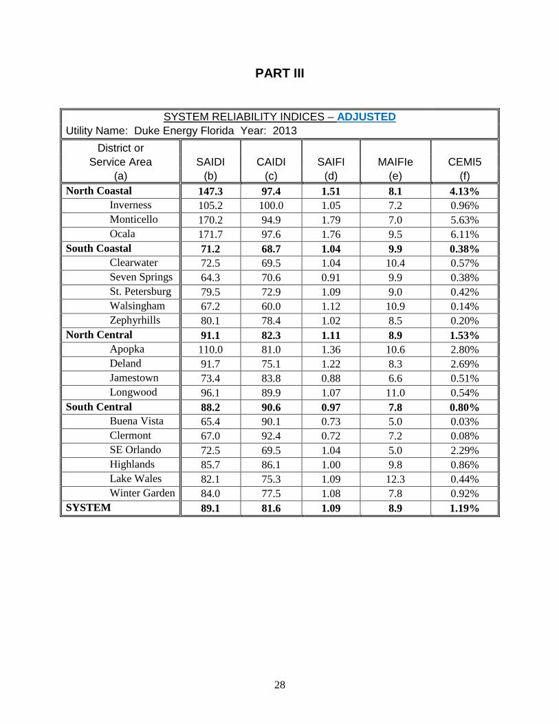
PART III
SYSTEM RELIABILITY INDICES – ADJUSTED Utility Name: Duke Energy Florida Year: 2013
District or Service Area SAIDI CAIDI SAIFI MAIFIe CEMI5
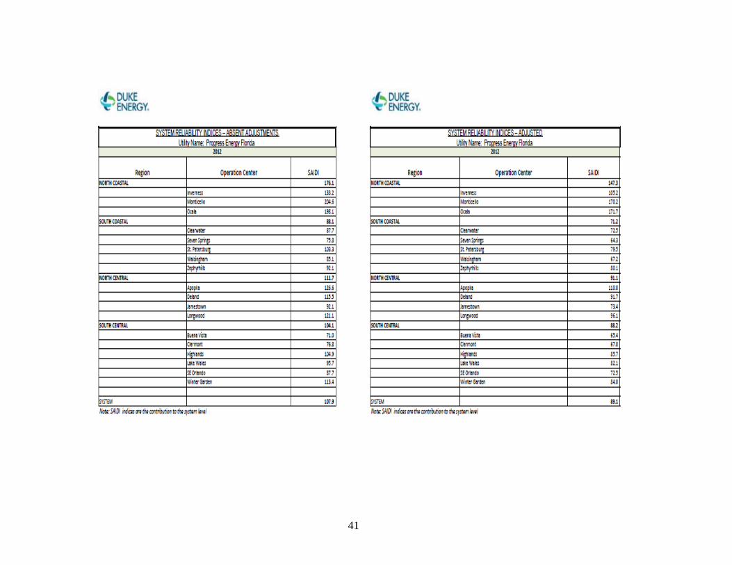
(a) (b) (c) (d) (e) (f) North Coastal 147.3 97.4 1.51 8.1 4.13%
Inverness 105.2 100.0 1.05 7.2 0.96% Monticello 170.2 94.9 1.79 7.0 5.63% Ocala 171.7 97.6 1.76 9.5 6.11%
South Coastal 71.2 68.7 1.04 9.9 0.38% Clearwater 72.5 69.5 1.04 10.4 0.57% Seven Springs 64.3 70.6 0.91 9.9 0.38% St. Petersburg 79.5 72.9 1.09 9.0 0.42% Walsingham 67.2 60.0 1.12 10.9 0.14% Zephyrhills 80.1 78.4 1.02 8.5 0.20%
North Central 91.1 82.3 1.11 8.9 1.53% Apopka 110.0 81.0 1.36 10.6 2.80% Deland 91.7 75.1 1.22 8.3 2.69% Jamestown 73.4 83.8 0.88 6.6 0.51% Longwood 96.1 89.9 1.07 11.0 0.54%
South Central 88.2 90.6 0.97 7.8 0.80% Buena Vista 65.4 90.1 0.73 5.0 0.03% Clermont 67.0 92.4 0.72 7.2 0.08% SE Orlando 72.5 69.5 1.04 5.0 2.29% Highlands 85.7 86.1 1.00 9.8 0.86% Lake Wales 82.1 75.3 1.09 12.3 0.44% Winter Garden 84.0 77.5 1.08 7.8 0.92%
SYSTEM 89.1 81.6 1.09 8.9 1.19%
29
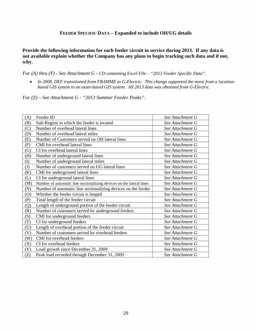
FEEDER SPECIFIC DATA – Expanded to include OH/UG details
Provide the following information for each feeder circuit in service during 2013. If any data is not available explain whether the Company has any plans to begin tracking such data and if not, why. For (A) thru (Y) - See Attachment G - CD containing Excel File – “2013 Feeder Specific Data”.
• In 2008, DEF transitioned from FRAMME to G-Electric. This change supported the move from a location-based GIS system to an asset-based GIS system. All 2013 data was obtained from G-Electric.
For (Z) – See Attachment G - “2013 Summer Feeder Peaks”. (A) Feeder ID See Attachment G (B) Sub-Region in which the feeder is located See Attachment G (C) Number of overhead lateral lines See Attachment G (D) Number of overhead lateral miles See Attachment G (E) Number of Customers served on OH lateral lines See Attachment G (F) CMI for overhead lateral lines See Attachment G (G) CI for overhead lateral lines See Attachment G (H) Number of underground lateral lines See Attachment G (I) Number of underground lateral miles See Attachment G (J) Number of customers served on UG lateral lines See Attachment G (K) CMI for underground lateral lines See Attachment G (L) CI for underground lateral lines See Attachment G (M) Number of automatic line sectionalizing devices on the lateral lines See Attachment G (N) Number of automatic line sectionalizing devices on the feeder See Attachment G (O) Whether the feeder circuit is looped See Attachment G (P) Total length of the feeder circuit See Attachment G (Q) Length of underground portion of the feeder circuit See Attachment G (R) Number of customers served by underground feeders See Attachment G (S) CMI for underground feeders See Attachment G (T) CI for underground feeders See Attachment G (U) Length of overhead portion of the feeder circuit See Attachment G (V) Number of customers served by overhead feeders See Attachment G (W) CMI for overhead feeders See Attachment G (X) CI for overhead feeders See Attachment G (Y) Load growth since December 31, 2009 See Attachment G (Z) Peak load recorded through December 31, 2009 See Attachment G
30
DISTRIBUTION SUBSTATION (Rule 25-6.0455, F.A.C.)
a. Describe the five year patterns/trends in reliability performance of distribution substations.
The five year patterns/trends in reliability performance of distribution substations is best described by the performance indices. These indices are used for calculating system reliability:
• SAIDI – System Average Interruption Duration Index (minutes/customer).
Reflects the average number of minutes a customer was without power system wide. It is determined by dividing the sum of customer-minutes of interruption by the average number of customers served during a period.
• CAIDI - Customer Average Interruption Duration Index (minutes/customer). CAIDI is
the average customer-minutes of interruption per customer interruption. It approximates the average length of time required to complete service restoration. It is determined by dividing the sum of all customer-minutes of interruption durations by the number of customer interruptions during a period. CAIDI measures how long it takes DEF to restore service after an interruption.
• SAIFI - System Average Interruption Frequency Index. SAIFI is the average number of
interruptions per customer per a certain period. It is determined by dividing the total number of customer interruptions by the average number of customers served during a period.
• FOHMY – Forced Outages per Hundred Miles per Year, measures the number of
transmission line events, momentary AND sustained, that are incurred per hundred circuit miles per year. This measure is often grouped by voltage class.
The following charts will show the trending for these Reliability Indices:
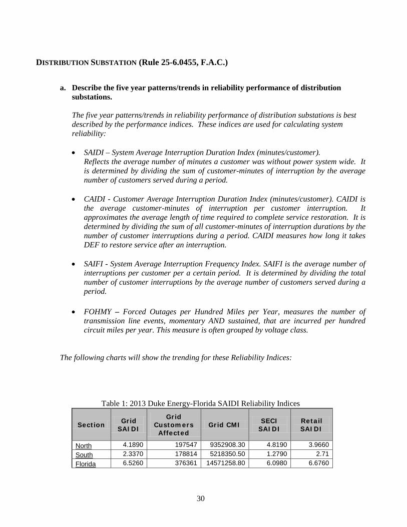
Table 1: 2013 Duke Energy-Florida SAIDI Reliability Indices
Section Grid SAIDI
Grid Customers Affected
Grid CMI SECI SAIDI
Retail SAIDI
North 4.1890 197547 9352908.30 4.8190 3.9660 South 2.3370 178814 5218350.50 1.2790 2.71 Florida 6.5260 376361 14571258.80 6.0980 6.6760
31
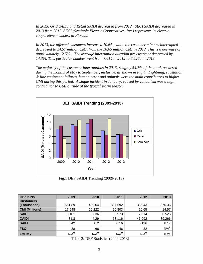
In 2013, Grid SAIDI and Retail SAIDI decreased from 2012. SECI SAIDI decreased in 2013 from 2012. SECI (Seminole Electric Cooperatives, Inc.) represents its electric cooperative members in Florida.
In 2013, the affected customers increased 10.6%, while the customer minutes interrupted decreased to 14.57 million CMI, from the 16.65 million CMI in 2012. This is a decrease of approximately 12.5%. The average interruption duration per customer decreased by 14.3%. This particular number went from 7.614 in 2012 to 6.5260 in 2013.
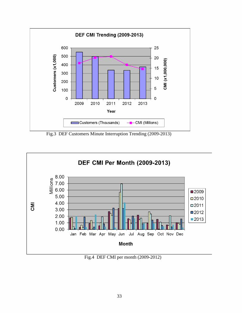
The majority of the customer interruptions in 2013, roughly 54.7% of the total, occurred during the months of May to September, inclusive, as shown in Fig.4. Lightning, substation & line equipment failures, human error and animals were the main contributors to higher CMI during this period. A single incident in January, caused by vandalism was a high contributor to CMI outside of the typical storm season.
Fig.1 DEF SAIDI Trending (2009-2013)
Grid KPIs 2009 2010 2011 2012 2013 Customers (Thousands) 551.89 499.04 337.592 336.43 376.36 CMI (Millions) 17.548 20.222 20.803 16.65 14.57 SAIDI 8.101 9.336 9.573 7.614 6.526 CAIDI 31.8 44.29 68.116 46.992 39.266 SAIFI 0.42 0.2 0.16 0.136 0.17 FSO 38 66 46 32 N/A*
FOHMY N/A* N/A* N/A* N/A* 8.21 Table 2: DEF Statistics (2009-2013)
32
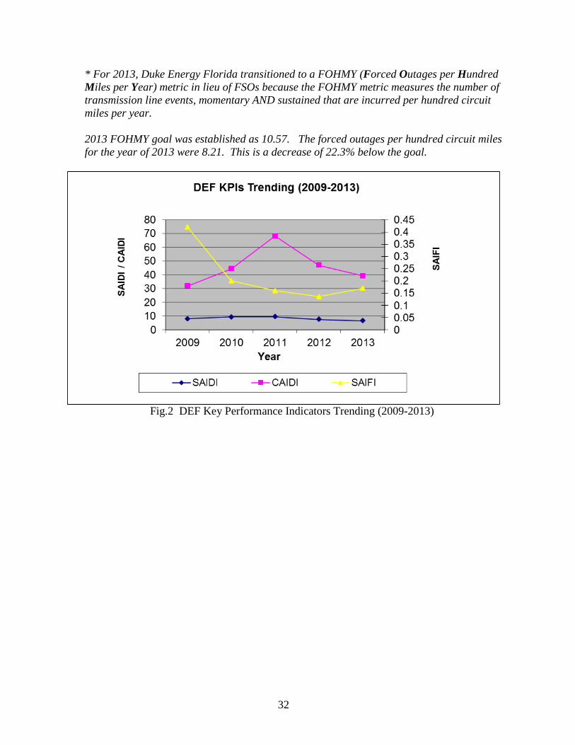
* For 2013, Duke Energy Florida transitioned to a FOHMY (Forced Outages per Hundred Miles per Year) metric in lieu of FSOs because the FOHMY metric measures the number of transmission line events, momentary AND sustained that are incurred per hundred circuit miles per year. 2013 FOHMY goal was established as 10.57. The forced outages per hundred circuit miles for the year of 2013 were 8.21. This is a decrease of 22.3% below the goal.
Fig.2 DEF Key Performance Indicators Trending (2009-2013)
33
Fig.3 DEF Customers Minute Interruption Trending (2009-2013)
Fig.4 DEF CMI per month (2009-2012)

34
a. Describe Company efforts to track the reliability of distribution substations.
Duke Energy Florida has an in-house database, Transmission Outage Management System (TOMS), which is used to keep track and record all the events that occur every day. It maintains all the indices mentioned above.
b. Describe the process used by your Company to identify and select the actions to
promote substation reliability. To identify and promote substation reliability, DEF uses different methods, such as monthly substation inspections, predictive and preventive maintenance, infra-red analysis, and numerous diagnostics tests. Once a problem is identified, another tool (Cascade) is used to track the efforts to correct it.
c. Provide the number of distribution substations inspected during normal operations
(non-storm related) for 2007, 2008, 2009, 2010, 2011 and 2012. Duke Energy Florida has inspected each of its current 475 substations on a routine basis since 2004 to present. These routine inspections are scheduled and performed monthly.

35
SUPPLEMENTAL DISTRIBUTION INFORMATION The next six pages contain the following information:
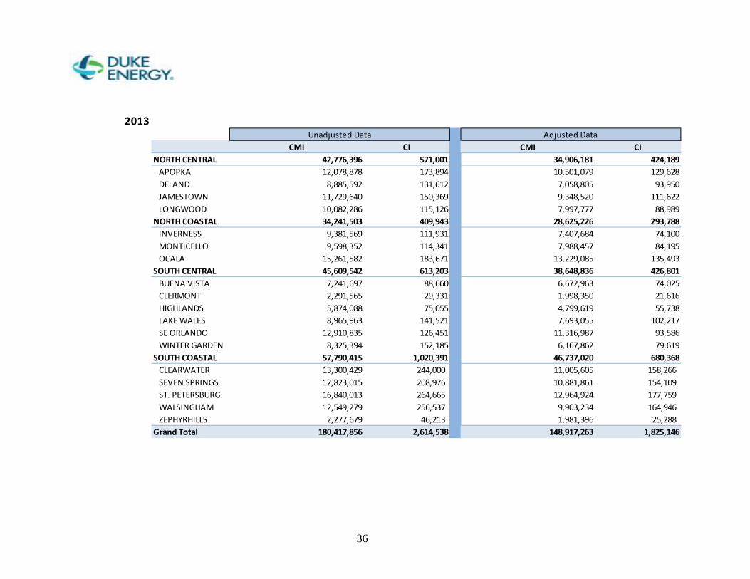
• CMI / CI by Operation Center for 2013 (Unadjusted/Adjusted)..…….Page 36
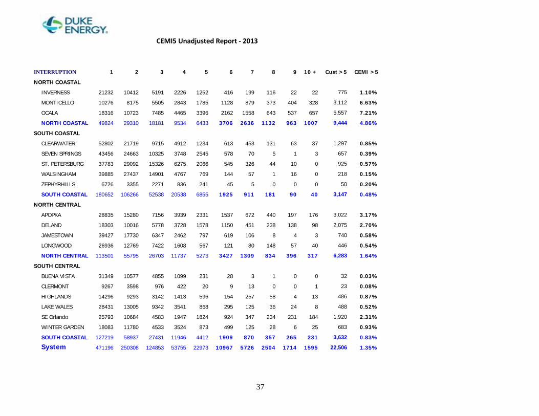
• CEMI5 by Operation Center for 2013 (Unadjusted )……………..…...Page 37
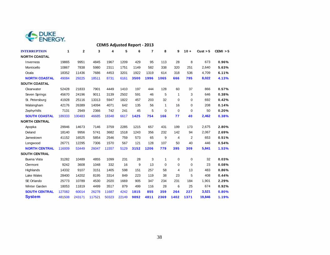
• CEMI5 by Operation Center for 2013 (Adjusted )………………..…...Page 38
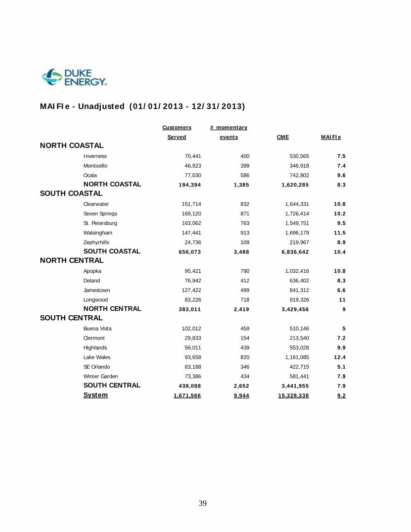
• MAIFIe by Operation Center for 2013 (Unadjusted)……...…………..Page 39
• MAIFIe by Operation Center for 2013 (Adjusted)…………………….Page 40
• SAIDI by Operation Center for 2013 (Unadjusted/Adjusted)…………Page 41
36
2013
CMI CI CMI CINORTH CENTRAL 42,776,396 571,001 34,906,181 424,189
APOPKA 12,078,878 173,894 10,501,079 129,628DELAND 8,885,592 131,612 7,058,805 93,950JAMESTOWN 11,729,640 150,369 9,348,520 111,622LONGWOOD 10,082,286 115,126 7,997,777 88,989
NORTH COASTAL 34,241,503 409,943 28,625,226 293,788INVERNESS 9,381,569 111,931 7,407,684 74,100MONTICELLO 9,598,352 114,341 7,988,457 84,195OCALA 15,261,582 183,671 13,229,085 135,493
SOUTH CENTRAL 45,609,542 613,203 38,648,836 426,801BUENA VISTA 7,241,697 88,660 6,672,963 74,025CLERMONT 2,291,565 29,331 1,998,350 21,616HIGHLANDS 5,874,088 75,055 4,799,619 55,738LAKE WALES 8,965,963 141,521 7,693,055 102,217SE ORLANDO 12,910,835 126,451 11,316,987 93,586WINTER GARDEN 8,325,394 152,185 6,167,862 79,619
SOUTH COASTAL 57,790,415 1,020,391 46,737,020 680,368CLEARWATER 13,300,429 244,000 11,005,605 158,266SEVEN SPRINGS 12,823,015 208,976 10,881,861 154,109ST. PETERSBURG 16,840,013 264,665 12,964,924 177,759WALSINGHAM 12,549,279 256,537 9,903,234 164,946ZEPHYRHILLS 2,277,679 46,213 1,981,396 25,288
Grand Total 180,417,856 2,614,538 148,917,263 1,825,146
Unadjusted Data Adjusted Data
37
CEMI5 Unadjusted Report - 2013
INTERRUPTION 1 2 3 4 5 6 7 8 9 10 + Cust >5 CEMI >5
NORTH COASTAL
INVERNESS 21232 10412 5191 2226 1252 416 199 116 22 22 775 1.10%
MONTICELLO 10276 8175 5505 2843 1785 1128 879 373 404 328 3,112 6.63%
OCALA 18316 10723 7485 4465 3396 2162 1558 643 537 657 5,557 7.21%
NORTH COASTAL 49824 29310 18181 9534 6433 3706 2636 1132 963 1007 9,444 4.86%
SOUTH COASTAL
CLEARWATER 52802 21719 9715 4912 1234 613 453 131 63 37 1,297 0.85%
SEVEN SPRINGS 43456 24663 10325 3748 2545 578 70 5 1 3 657 0.39%
ST. PETERSBURG 37783 29092 15326 6275 2066 545 326 44 10 0 925 0.57%
WALSINGHAM 39885 27437 14901 4767 769 144 57 1 16 0 218 0.15%
ZEPHYRHILLS 6726 3355 2271 836 241 45 5 0 0 0 50 0.20%
SOUTH COASTAL 180652 106266 52538 20538 6855 1925 911 181 90 40 3,147 0.48%
NORTH CENTRAL
APOPKA 28835 15280 7156 3939 2331 1537 672 440 197 176 3,022 3.17%
DELAND 18303 10016 5778 3728 1578 1150 451 238 138 98 2,075 2.70%
JAMESTOWN 39427 17730 6347 2462 797 619 106 8 4 3 740 0.58%
LONGWOOD 26936 12769 7422 1608 567 121 80 148 57 40 446 0.54%
NORTH CENTRAL 113501 55795 26703 11737 5273 3427 1309 834 396 317 6,283 1.64%
SOUTH CENTRAL
BUENA VISTA 31349 10577 4855 1099 231 28 3 1 0 0 32 0.03%
CLERMONT 9267 3598 976 422 20 9 13 0 0 1 23 0.08%
HIGHLANDS 14296 9293 3142 1413 596 154 257 58 4 13 486 0.87%
LAKE WALES 28431 13005 9342 3541 868 295 125 36 24 8 488 0.52%
SE Orlando 25793 10684 4583 1947 1824 924 347 234 231 184 1,920 2.31%
WINTER GARDEN 18083 11780 4533 3524 873 499 125 28 6 25 683 0.93%
SOUTH COASTAL 127219 58937 27431 11946 4412 1909 870 357 265 231 3,632 0.83%
System 471196 250308 124853 53755 22973 10967 5726 2504 1714 1595 22,506 1.35%
38
CEMI5 Adjusted Report - 2013 INTERRUPTION 1 2 3 4 5 6 7 8 9 10 + Cust >5 CEMI >5
NORTH COASTAL
Inverness 19865 9951 4845 1967 1209 429 95 113 28 8 673 0.96%
Monticello 10867 7838 5980 2311 1751 1149 582 338 320 251 2,640 5.63%
Ocala 18352 11436 7686 4453 3201 1922 1319 614 318 536 4,709 6.11%
NORTH COASTAL 49084 29225 18511 8731 6161 3500 1996 1065 666 795 8,022 4.13%
SOUTH COASTAL
Clearwater 52428 21833 7901 4449 1410 197 444 128 60 37 866 0.57%
Seven Springs 45670 24196 9011 3139 2502 591 46 5 1 3 646 0.38%
St. Petersburg 41928 25116 13313 5947 1822 457 203 32 0 0 692 0.42%
Walsingham 42176 26389 14094 4071 642 135 56 1 16 0 208 0.14%
Zephyrhills 7131 2949 2366 742 241 45 5 0 0 0 50 0.20%
SOUTH COASTAL 189333 100483 46685 18348 6617 1425 754 166 77 40 2,462 0.38%
NORTH CENTRAL
Apopka 29946 14673 7146 3759 2285 1215 657 431 199 173 2,675 2.80%
Deland 18140 9956 5741 3682 1518 1243 356 232 142 94 2,067 2.69%
Jamestown 41152 16525 5854 2546 759 573 65 9 4 2 653 0.51%
Longwood 26771 12295 7306 1570 567 121 128 107 50 40 446 0.54%
NORTH CENTRAL 116009 53449 26047 11557 5129 3152 1206 779 395 309 5,841 1.53%
SOUTH CENTRAL
Buena Vista 31282 10489 4855 1099 231 28 3 1 0 0 32 0.03%
Clermont 9242 3608 1048 332 16 9 13 0 0 0 23 0.08%
Highlands 14332 9107 3151 1405 598 151 257 58 4 13 483 0.86%
Lake Wales 28400 14202 8195 3314 849 223 119 38 23 5 408 0.44%
SE Orlando 25773 10789 4530 2020 1669 905 347 234 231 184 1,901 2.29%
Winter Garden 18053 11819 4499 3517 879 499 116 28 6 25 674 0.92%
SOUTH CENTRAL 127082 60014 26278 11687 4242 1815 855 359 264 227 3,521 0.80%
System 481508 243171 117521 50323 22149 9892 4811 2369 1402 1371 19,846 1.19%
39
MAIFIe - Unadjusted (01/01/2013 - 12/31/2013)
Customers # momentary
Served events CME MAIFIe
NORTH COASTAL
Inverness 70,441 400 530,565 7.5
Monticello 46,923 399 346,918 7.4
Ocala 77,030 586 742,802 9.6
NORTH COASTAL 194,394 1,385 1,620,285 8.3
SOUTH COASTAL
Clearwater 151,714 832 1,644,331 10.8
Seven Springs 169,120 871 1,726,414 10.2
St. Petersburg 163,062 763 1,549,751 9.5
Walsingham 147,441 913 1,696,179 11.5
Zephyrhills 24,736 109 219,967 8.9
SOUTH COASTAL 656,073 3,488 6,836,642 10.4
NORTH CENTRAL
Apopka 95,421 790 1,032,416 10.8
Deland 76,942 412 636,402 8.3
Jamestown 127,422 499 841,312 6.6
Longwood 83,226 718 919,326 11
NORTH CENTRAL 383,011 2,419 3,429,456 9
SOUTH CENTRAL
Buena Vista 102,012 459 510,146 5
Clermont 29,833 154 213,540 7.2
Highlands 56,011 439 553,028 9.9
Lake Wales 93,658 820 1,161,085 12.4
SE Orlando 83,188 346 422,715 5.1
Winter Garden 73,386 434 581,441 7.9
SOUTH CENTRAL 438,088 2,652 3,441,955 7.9
System 1,671,566 9,944 15,328,338 9.2
40
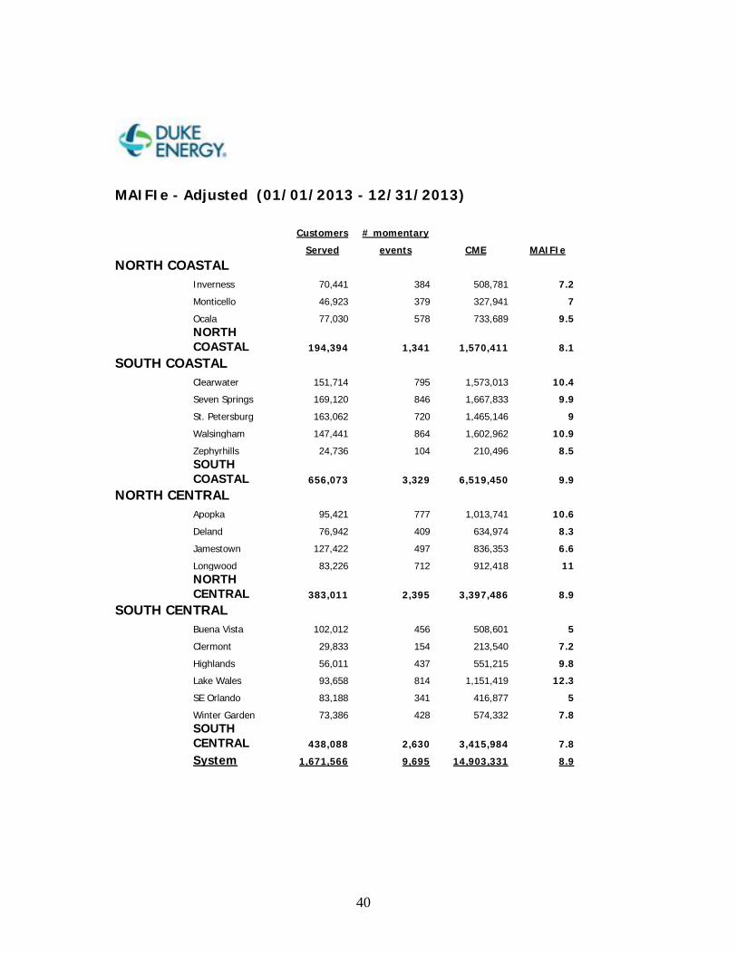
MAIFIe - Adjusted (01/01/2013 - 12/31/2013)
Customers # momentary
Served events CME MAIFIe
NORTH COASTAL
Inverness 70,441 384 508,781 7.2
Monticello 46,923 379 327,941 7
Ocala 77,030 578 733,689 9.5
NORTH COASTAL 194,394 1,341 1,570,411 8.1
SOUTH COASTAL
Clearwater 151,714 795 1,573,013 10.4
Seven Springs 169,120 846 1,667,833 9.9
St. Petersburg 163,062 720 1,465,146 9
Walsingham 147,441 864 1,602,962 10.9
Zephyrhills 24,736 104 210,496 8.5
SOUTH COASTAL 656,073 3,329 6,519,450 9.9
NORTH CENTRAL
Apopka 95,421 777 1,013,741 10.6
Deland 76,942 409 634,974 8.3
Jamestown 127,422 497 836,353 6.6
Longwood 83,226 712 912,418 11
NORTH CENTRAL 383,011 2,395 3,397,486 8.9
SOUTH CENTRAL
Buena Vista 102,012 456 508,601 5
Clermont 29,833 154 213,540 7.2
Highlands 56,011 437 551,215 9.8
Lake Wales 93,658 814 1,151,419 12.3
SE Orlando 83,188 341 416,877 5
Winter Garden 73,386 428 574,332 7.8
SOUTH CENTRAL 438,088 2,630 3,415,984 7.8
System 1,671,566 9,695 14,903,331 8.9
41
42
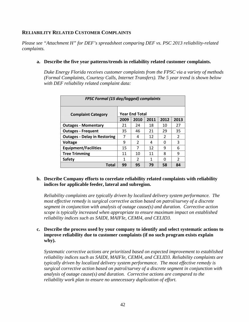
RELIABILITY RELATED CUSTOMER COMPLAINTS
Please see “Attachment H” for DEF’s spreadsheet comparing DEF vs. PSC 2013 reliability-related complaints.
a. Describe the five year patterns/trends in reliability related customer complaints.
Duke Energy Florida receives customer complaints from the FPSC via a variety of methods (Formal Complaints, Courtesy Calls, Internet Transfers). The 5 year trend is shown below with DEF reliability related complaint data:
b. Describe Company efforts to correlate reliability related complaints with reliability indices for applicable feeder, lateral and subregion.
Reliability complaints are typically driven by localized delivery system performance. The most effective remedy is surgical corrective action based on patrol/survey of a discrete segment in conjunction with analysis of outage cause(s) and duration. Corrective action scope is typically increased when appropriate to ensure maximum impact on established reliability indices such as SAIDI, MAIFIe, CEMI4, and CELID3.
c. Describe the process used by your company to identify and select systematic actions to
improve reliability due to customer complaints (if no such program exists explain why).
Systematic corrective actions are prioritized based on expected improvement to established reliability indices such as SAIDI, MAIFIe, CEMI4, and CELID3. Reliability complaints are typically driven by localized delivery system performance. The most effective remedy is surgical corrective action based on patrol/survey of a discrete segment in conjunction with analysis of outage cause(s) and duration. Corrective actions are compared to the reliability work plan to ensure no unnecessary duplication of effort.
FPSC Formal (15 day/logged) complaints
Complaint Category Year End Total 2009 2010 2011 2012 2013
Outages - Momentary 21 24 18 10 27 Outages - Frequent 35 46 21 29 35 Outages - Delay in Restoring 7 4 12 2 2 Voltage 9 2 4 0 3 Equipment/Facilities 15 7 12 9 6 Tree Trimming 11 10 11 8 9 Safety 1 2 1 0 2
Total 99 95 79 58 84
43
II. STORM HARDENED FACILITIES
Pursuant to the Stipulation regarding the “Process within the Process” entered into and filed jointly by the third-party attachers and IOU’s with the FPSC on September 26, 2007, paragraph 7 requires each electric utility to file by March 1 each year a status report of its implementation of its storm hardening plan. Please see Attachment I - “Spreadsheet of Storm Hardening Project Status”.
a. Describe each storm hardening activity undertaken in the field during 2013.
Distribution In addition to the activities identified in DEF’s Storm Hardening Plan (Attachment J), Wood Pole Inspection Plan (Attachment K), and other initiatives identified and discussed herein, Duke Energy Florida Distribution undertook the following specific activities that deliver a storm hardening benefit during 2013: Existing Overhead to Underground Conversion: See Attachment L - “Major Conversions Historical Data”. New Construction Cable footage installed underground: In 2013, DEF installed 196 circuit miles of new underground cable. Overall, the DEF distribution system consists of 42.1% primary underground circuit miles (13,176 circuit miles).
Network Maintenance and Replacement: 2013 Actuals - $736k Switchgear Replacement 2013 Actuals - $1.2m
Midfeeder Electronic Sectionalizing (Reclosers): 2013Actuals - $870k
Wood Pole Inspection and Treatment: 2013 Actuals - $2.7m Wood Pole Replacement: 2013 Actuals - $17.3m Padmount Transformer Replacement: 2013 Actuals - $8.1m Storm Hardening Projects 2013 Actuals - $4.2m
44
Transmission In addition to the activities identified in DEF’s Storm Hardening Plan (Attachment J), Wood Pole Inspection Plan (Attachment K), and other initiatives identified and discussed herein, Duke Energy Florida Transmission undertook the following specific Storm Hardening Activities during 2013:
Maintenance Change outs: Duke Energy Florida Transmission is installing either steel or concrete poles when replacing existing wood poles. This activity resulted in the replacement of 1347 wood poles with steel or concrete during 2013. DOT/Customer Relocations and Line Upgrades and Additions: Duke Energy Florida Transmission will design any DOT or Customer Requested Relocations and any line upgrades or additions to meet or exceed the current NESC Code Requirements and will construct these projects with either steel or concrete poles. This activity resulted in replacement of approximately 1672 poles with steel or concrete during 2013.
b. Describe the process used by your company to identify the location and select the scope of
storm hardening projects.
Distribution The location and scope of projects that deliver hardening benefits varies by type of construction, maintenance, or replacement activity. Primary factors considered include operational and storm performance, remaining life, condition assessment of equipment as determined by inspection, and cost to repair or replace. In all cases, the cost to install, maintain, or replace equipment is balanced against the expected long term operational and cost benefit. For additional information, please see Attachment J- DEF’s Storm Hardening Plan. Transmission Maintenance Change outs Poles that require change out are identified by Procedure MNT-TRMX-00053, “Ground Patrols” (Attachment M). The change out schedule is determined by the condition of the wood pole based upon inspector experience. DOT/Customer Relocations Poles that are changed out and upgraded are identified by requests from DOT or customers. Line Upgrades and Additions Duke Energy Florida Transmission Planning will determine where and when lines need to be upgraded. For additional information, please see Attachment J - DEF’s Storm Hardening Plan.
45
c. Provide the costs incurred and any quantified expected benefits.
Distribution See Subsection (a) above. Transmission Line Maintenance Change outs Duke Energy Florida Transmission spent approximately $21,364,389 for Capital Improvements in 2013. Capital Improvements includes pole change outs and complete insulator replacements.
Quantified benefits will be a stronger and more consistent material supporting Transmission Circuits. Over the next 10 years, the percentage of wood poles on Duke Energy Florida’s Transmission system should reduce wood poles on the system from approximately 75% today to 50%. DOT/Customer Relocations and Line Upgrades and Additions Duke Energy Florida Transmission spent approximately $118,914,634 for DOT/Customer Relocations and Line Upgrades and Additions in 2013. Quantified benefits will be a stronger and more consistent material supporting Transmission Circuits. Over the next 10 years, the percentage of wood poles on Duke Energy’s Transmission system should reduce wood poles on the system from approximately 75% today to 50%.
d. Discuss any 2014 projected activities and budget levels.
Distribution Duke Energy Florida Distribution’s storm hardening strategy and activities for 2014 are still ongoing and under development. At this time, however, Duke Energy Distribution reports as follows:
Existing Overhead to Underground Conversion: Major Underground Conversions are a customer driven activity based upon a willingness to pay the conversion costs. While specific annual totals are difficult to forecast, the trend indicated by Attachment L, “Major Conversions Historical Data” over the last 11 years is expected to continue. New Construction Cable footage installed underground: The specific span miles of new underground cable installed is driven by the level of new connect activity. While the number of span miles installed varies from year to year, the percentage of new primary distribution span miles installed underground is expected to continue.

46
Network Maintenance and Replacement: 2014 Projections - $705k Switchgear Replacement 2014 Projections - $1.46m
Wood Pole Inspection and Treatment: 2014 Projections - $2.7m Wood Pole Replacement: 2014 Projections - $15.9m Padmount Transformer Replacement: 2014Projections - $9.9m Storm Hardening Projects 2014 Projections - $5.9M
Transmission Duke Energy Florida Transmission’s storm hardening strategy and activities for 2014 are still ongoing and under development. At this time, however, Duke Energy Transmission reports as follows:
Line Maintenance Change outs Duke Energy Florida Transmission should replace approximately 700 poles in 2014. Capital Budget for Line Maintenance is $19,615,240 for 2014 which includes pole change outs, insulator replacements and any overhead ground wire (OHGW) replacements. DOT/Customer Relocations and Line Upgrades and Additions Duke Energy Florida Transmission should replace approximately 1265 poles in 2014. Current identified DOT/Customer Relocation Projects and Line Upgrades and Additions has a capital budget of $95 million.

47
III. STORM SEASON READINESS
a. Describe the efforts the Company is taking to be storm-ready by June 1, 2013
Please see Attachment N – DEF’s April 3, 2013 FPSC Presentation “Storm Season Readiness”
Distribution
DEF's Distribution Storm Plan has been reviewed and revised as of June 2013 (See Attachment Y). The Distribution organization will conduct a storm readiness drill in April of 2014. By the start of storm season, all feeder backbones will be surveyed for tree conditions and corrective work completed. System reliability is continually monitored and upgraded through our storm hardening efforts. Critical restoration material and fuel will be ready and available from multiple sources, and we have taken steps to ensure that outside line and tree trimming resources are ready and available.
Transmission
DEF’s Transmission Storm Plan has been reviewed and revised as of May 1, 2013 (Attachment Z). The Transmission Department conducted a storm readiness drill during the week of April 23, 2012. Transmission will conduct its 2014 storm drill in conjunction with Distribution. Also, aerial patrols for DEF’s entire transmission system took place between March-June and September-December, 2013. The next aerial patrols are scheduled between March-June and September-December, 2014.

48
IV. WOOD POLE INSPECTION PROGRAM
a. Provide a detailed description of the Company’s wood pole inspection program. Duke Energy Florida’s wood pole inspection program philosophy is to determine the condition of the wood pole plant and provide remediation for any wood poles that are showing signs of decay or fall below the minimum strength requirements outlined by NESC standards.
Duke Energy is utilizing the expertise of Osmose Utilities Services, Inc., to perform the inspections on an eight year cycle. Osmose is using visual inspection, sound and boring, and full excavation down to 18 inches below ground line to determine the condition of all poles with the exception of CCA poles less than 16 years of age and poles that cannot be excavated due to obstructions. For CCA poles less than 16 years of age, Osmose is using visual inspection and sound, as well as, selective boring to determine the pole condition. In addition, Osmose is providing remediation of decayed poles through external and internal treatments. If the pole is below NESC standards and has the minimum remaining wood above ground line, Osmose will also reinforce the pole back to original strength. For additional information, please see Attachment K - “Wood Pole Inspection Plan”.
b. 2013 accomplishments Distribution Duke Energy, Florida inspected 97,071 wood distribution poles during 2013. This completes 7 yrs. & 9 months of an 8 year inspection cycle. This total should keep us on target to meet an 8 year pole inspection cycle. In addition to the inspections, GPS coordinates and physical attributes were updated and/or verified and inspection results were collected in a central database on all poles inspected. Transmission
In 2013, DEF’s Transmission ground patrol inspected 14,064 wood pole structures. This represents approximately 49% of the wood pole structures on the DEF Transmission system.
c. Projected accomplishments for 2014 Distribution Among other things, Duke Energy’s goal for 2014 is to complete inspections on cycle one of the 8 year pole inspection program and to continue on with the start of cycle two. Duke Energy will continue to utilize the same inspection procedures in 2014 that we have in the past. Transmission
49
Current plans are to inspect approximately 1/3 to 1/5 of the system, which equates to approximately 1,000 miles of Transmission Circuits (or approximately 7,500 wood structures). We will have a 3rd party contract crew complete ground line sound and bore inspections for approximately 7,500 wood poles. We also will aerial patrol the entire transmission system two (2) times during 2014. We will perform a ground inspection on all lines 200kv and higher. These patrols will begin in March 2014.
d. Wood pole inspection reports. Each wood pole inspection report contains the following:
• A description of the methods used for structural analysis and pole inspection, • A description of the selection criteria that was used to determine which poles would be
inspected, and • A summary report of the inspection data.
Distribution Please see Attachment O - 2013 Annual Wood Pole Inspection Report filed with the FPSC on February 28, 2014. For a description of the methods used for structural analysis and pole inspection – please refer to Attachment K - “Wood Pole Inspection Plan”, pages 1 - 4 and 6 - 8. For the summary report of the inspection data - See Attachment P - CD Rom containing Excel file - “2013 Distribution Pole Inspection Data”.
Transmission Please see Attachment O - 2013 Annual Wood Pole Inspection Report filed with the FPSC on February 28, 2014. For a description of the methods used for structural analysis and pole inspection – please refer to Attachment K - “Wood Pole Inspection Plan”, pages 1 - 4 and 6 - 8. For the summary report of the inspection data – See Attachment Q – CD containing Excel files - “2013 Pole Data” and “2013 Structure Data”.

50
CCA Pole Sampling Report
Pursuant to Order No. PSC-08-0615-PAA-EI issued September 23, 2008 in Docket No. 080219-EI, the Commission approved modification to the sounding and boring excavation requirements of Order No. 06-0144-PAA-EI with regard to CCA wood poles less than 16 years old. On Pages 3 and 4 of Order No. PSC-08-0615-PAA-EI, it states,
“ORDERED that, consistent with the deviation granted to Gulf Power Company in
Order No. PSC-07-0078-PAA-EU, Progress Energy Florida, Inc., Florida Power & Light Company, and Tampa Electric Company shall be required to sound and selectively bore all CCA poles under the age of 16 years, but shall not be required to perform full excavation on these poles. It is further
ORDERED that Progress Energy Florida, Inc., Florida Power & Light Company, and Tampa Electric Company shall also be required to perform full excavation sampling to validate their inspection method. It is further
ORDERED that the results of the utilities’ sampling shall be filed in their annual distribution reliability reports.”
2013 CCA Pole Sampling Results Please see Attachment O – Duke Energy’s 2013 Annual Wood Pole Inspection Report filed with the FPSC on February 28, 2014. The “CCA Sampling Results for 2013” is included in Duke Energy’s Wood Pole Inspection Report as “Attachment B”.
51
V. EIW INITIATIVES
VEGETATION MANAGEMENT – THREE YEAR CYCLE (Initiative 1)
a. Provide a complete description of the Company’s vegetation management program (policies, guidelines, practices) for 2013 and 2014 in terms of both activity and costs.
• See Attachment R - “DEF’s Storm Preparedness Plan”. • See Attachment S - “Internal Policy & Guidelines”. • For activities and costs - See information herein on pages 51-58.
b. Describe tree clearing practices in utility easements and authorized rights-of-ways. See Attachment S - “Internal Policy & Guidelines”.
c. Identify relevant portions of utility tariffs pertaining to utility vegetation management activities within easements and authorized rights-of-ways. DEF’s tariffs do not contain specific language pertaining to utility vegetation management activities within easements and authorized rights-of-ways.
d. Describe tree removal practices for trees that abut and/or intrude into easements and authorized rights-of-ways. See Attachment S - “Internal Policy & Guidelines”.
e. Describe tree clearing practices outside of utility easements and authorized rights-of-ways. See Attachment S - “Internal Policy & Guidelines”.
f. Identify relevant portions of utility tariffs pertaining to utility vegetation management activities outside of easements and authorized rights-of-ways. DEF’s tariffs do not contain specific language pertaining to utility vegetation management activities outside of easements and authorized rights-of-ways.
g. Describe tree removal practices for trees outside of easements and authorized rights-of-ways. See Attachment S - “Internal Policy & Guidelines”.
h. Identify relevant portions of utility tariffs pertaining to customer vegetation management obligations as a term or condition of electric service. There is no specific language in DEF’s tariffs that pertain to customer vegetation management obligations as a term or condition of electric service. However, in Section 4 of DEF’s tariff book, Sheets 4.11 and 4.123, reference is made to a customer’s responsibility regarding vegetation management.
i. Describe Company practices regarding customer trim requests.
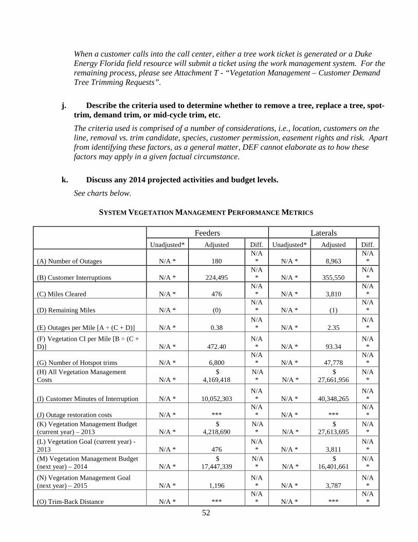
52
When a customer calls into the call center, either a tree work ticket is generated or a Duke Energy Florida field resource will submit a ticket using the work management system. For the remaining process, please see Attachment T - “Vegetation Management – Customer Demand Tree Trimming Requests”.
j. Describe the criteria used to determine whether to remove a tree, replace a tree, spot-trim, demand trim, or mid-cycle trim, etc. The criteria used is comprised of a number of considerations, i.e., location, customers on the line, removal vs. trim candidate, species, customer permission, easement rights and risk. Apart from identifying these factors, as a general matter, DEF cannot elaborate as to how these factors may apply in a given factual circumstance.
k. Discuss any 2014 projected activities and budget levels.
See charts below.
SYSTEM VEGETATION MANAGEMENT PERFORMANCE METRICS
Feeders Laterals
Unadjusted* Adjusted Diff. Unadjusted* Adjusted Diff.
(A) Number of Outages N/A * 180 N/A
* N/A * 8,963 N/A
*
(B) Customer Interruptions N/A * 224,495 N/A
* N/A * 355,550 N/A
*
(C) Miles Cleared N/A * 476 N/A
* N/A * 3,810 N/A
*
(D) Remaining Miles N/A * (0) N/A
* N/A * (1) N/A
*
(E) Outages per Mile [A ÷ (C + D)] N/A * 0.38 N/A
* N/A * 2.35 N/A
* (F) Vegetation CI per Mile [B ÷ (C + D)] N/A * 472.40
N/A * N/A * 93.34
N/A *
(G) Number of Hotspot trims N/A * 6,800 N/A
* N/A * 47,778 N/A
* (H) All Vegetation Management Costs N/A *
$ 4,169,418
N/A * N/A *
$ 27,661,956
N/A *
(I) Customer Minutes of Interruption N/A * 10,052,303 N/A
* N/A * 40,348,265 N/A
*
(J) Outage restoration costs N/A * *** N/A
* N/A * *** N/A
* (K) Vegetation Management Budget (current year) – 2013 N/A *
$ 4,218,690
N/A * N/A *
$ 27,613,695
N/A *
(L) Vegetation Goal (current year) - 2013 N/A * 476
N/A * N/A * 3,811
N/A *
(M) Vegetation Management Budget (next year) – 2014 N/A *
$ 17,447,339
N/A * N/A *
$ 16,401,661
N/A *
(N) Vegetation Management Goal (next year) – 2015 N/A * 1,196
N/A * N/A * 3,787
N/A *
(O) Trim-Back Distance N/A * *** N/A
* N/A * *** N/A
*

53
Note: Total miles cleared in 2013 was 4,286. Annual variations from target are expected as DEF manages resource and unit cost factors associated with its integrated vegetation management plan. Based on the 3-year feeder / 5- year lateral tree trimming cycle, since 2006 initiation, DEF is at 17% of total 3-year cycle feeder miles and 57% of total 5-year cycle lateral miles. * There is no unadjusted data on tree caused storm events that would be relevant to DEF’s tree trimming
program. It would not be reasonably possible to gather this data and furthermore the data would not be accurate if we could obtain it. It would take extraordinary effort and considerable conjecture to estimate the impact of trees on DEF’s distribution system for outage causes that are currently coded “storm”. It would not be reasonably possible to gather such data because contractors move around the System and operate under a myriad of restoration contracts and agreements. To track this data, it would require the establishment of both a financially based tracking system to monitor costs as well as crew activity system-wide during a catastrophic event. Additionally, it is not practical to perform a forensic analysis of outages during a catastrophic event for the purpose of obtaining the root cause since several agencies assist in the effort as well as the magnitude of damage that impact a localized area of the system. During a storm event, outage tracking migrates from Outage Management System event to a Damage Assessment event. As such, our ability to capture reliable data becomes significantly compromised.
** This data is actual complete in 2013 and scheduled in 2014.
*** Distance varies according to species’ growth rates.
**** This data was not previously tracked. A means of extracting tree outage data from total storm restoration costs is still being investigated.
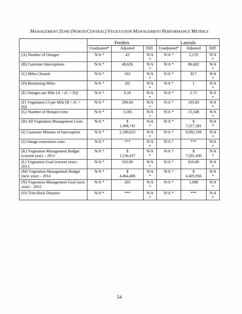
54
MANAGEMENT ZONE (NORTH CENTRAL) VEGETATION MANAGEMENT PERFORMANCE METRICS
Feeders Laterals
Unadjusted* Adjusted Diff. Unadjusted* Adjusted Diff.
(A) Number of Outages N/A * 43 N/A *
N/A * 2,219 N/A *
(B) Customer Interruptions N/A * 48,626 N/A *
N/A * 86,602 N/A *
(C) Miles Cleared N/A * 163 N/A *
N/A * 817 N/A *
(D) Remaining Miles N/A * (0) N/A *
N/A * 1 N/A *
(E) Outages per Mile [A ÷ (C + D)] N/A * 0.26 N/A *
N/A * 2.71 N/A *
(F) Vegetation CI per Mile [B ÷ (C + D)]
N/A * 299.64 N/A *
N/A * 105.83 N/A *
(G) Number of Hotspot trims N/A * 3,185 N/A *
N/A * 15,548 N/A *
(H) All Vegetation Management Costs N/A * $ 1,498,741
N/A *
N/A * $ 7,317,381
N/A *
(I) Customer Minutes of Interruption N/A * 2,180,653 N/A *
N/A * 9,992,194 N/A *
(J) Outage restoration costs N/A * *** N/A *
N/A * *** N/A *
(K) Vegetation Management Budget (current year) – 2013
N/A * $ 1,536,437
N/A *
N/A * $ 7,501,430
N/A *
(L) Vegetation Goal (current year) - 2013
N/A * 163.00 N/A *
N/A * 816.00 N/A *
(M) Vegetation Management Budget (next year) – 2014
N/A * $ 4,464,406
N/A *
N/A * $ 4,405,956
N/A *
(N) Vegetation Management Goal (next year) – 2015
N/A * 265 N/A *
N/A * 1,098 N/A *
(O) Trim-Back Distance N/A * *** N/A *
N/A * *** N/A *
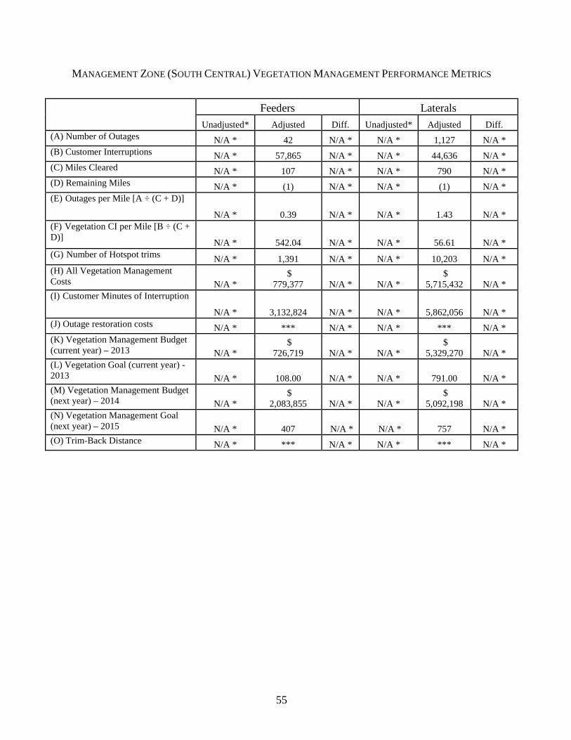
55
MANAGEMENT ZONE (SOUTH CENTRAL) VEGETATION MANAGEMENT PERFORMANCE METRICS
Feeders Laterals
Unadjusted* Adjusted Diff. Unadjusted* Adjusted Diff. (A) Number of Outages N/A * 42 N/A * N/A * 1,127 N/A * (B) Customer Interruptions N/A * 57,865 N/A * N/A * 44,636 N/A * (C) Miles Cleared N/A * 107 N/A * N/A * 790 N/A * (D) Remaining Miles N/A * (1) N/A * N/A * (1) N/A * (E) Outages per Mile [A ÷ (C + D)]
N/A * 0.39 N/A * N/A * 1.43 N/A * (F) Vegetation CI per Mile [B ÷ (C + D)] N/A * 542.04 N/A * N/A * 56.61 N/A * (G) Number of Hotspot trims N/A * 1,391 N/A * N/A * 10,203 N/A * (H) All Vegetation Management Costs N/A *
$ 779,377 N/A * N/A *
$ 5,715,432 N/A *
(I) Customer Minutes of Interruption
N/A * 3,132,824 N/A * N/A * 5,862,056 N/A * (J) Outage restoration costs N/A * *** N/A * N/A * *** N/A * (K) Vegetation Management Budget (current year) – 2013 N/A *
$ 726,719 N/A * N/A *
$ 5,329,270 N/A *
(L) Vegetation Goal (current year) - 2013 N/A * 108.00 N/A * N/A * 791.00 N/A * (M) Vegetation Management Budget (next year) – 2014 N/A *
$ 2,083,855 N/A * N/A *
$ 5,092,198 N/A *
(N) Vegetation Management Goal (next year) – 2015 N/A *
407 N/A * N/A *
757 N/A *
(O) Trim-Back Distance N/A * *** N/A * N/A * *** N/A *

56
MANAGEMENT ZONE (NORTH COASTAL) VEGETATION MANAGEMENT PERFORMANCE METRICS
Feeders Laterals Unadjusted* Adjusted Diff. Unadjusted* Adjusted Diff.
(A) Number of Outages N/A * 57 N/A *
N/A * 3,035 N/A *
(B) Customer Interruptions N/A * 48,553 N/A *
N/A * 120,089 N/A *
(C) Miles Cleared N/A * 98 N/A *
N/A * 1,640 N/A *
(D) Remaining Miles N/A * 0 N/A *
N/A * 1 N/A *
(E) Outages per Mile [A ÷ (C + D)] N/A * 0.58 N/A *
N/A * 1.85 N/A *
(F) Vegetation CI per Mile [B ÷ (C + D)]
N/A * 492.19 N/A *
N/A * 73.21 N/A *
(G) Number of Hotspot trims N/A * 994 N/A *
N/A * 15,571 N/A *
(H) All Vegetation Management Costs
N/A * $ 451,182
N/A *
N/A * $ 7,068,526
N/A *
(I) Customer Minutes of Interruption N/A * 2,401,385 N/A *
N/A * 14,195,903 N/A *
(J) Outage restoration costs N/A * *** N/A *
N/A * *** N/A *
(K) Vegetation Management Budget (current year) – 2013
N/A * $ 433,578
N/A *
N/A * $ 6,792,730
N/A *
(L) Vegetation Goal (current year) - 2013
N/A * 98 N/A *
N/A * 1,639 N/A *
(M) Vegetation Management Budget (next year) – 2014
N/A * $ 5,690,887
N/A *
N/A * $ 2,525,383
N/A *
(N) Vegetation Management Goal (next year) – 2015
N/A * 254 N/A *
N/A * 795 N/A *
(O) Trim-Back Distance N/A * *** N/A *
N/A * *** N/A *
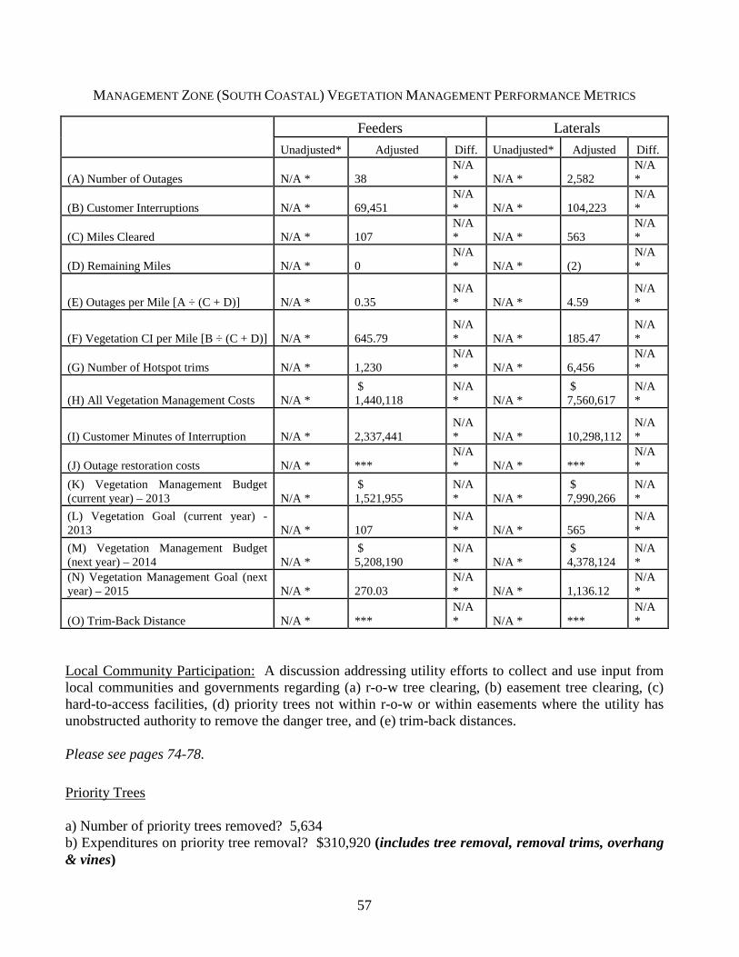
57
MANAGEMENT ZONE (SOUTH COASTAL) VEGETATION MANAGEMENT PERFORMANCE METRICS
Local Community Participation: A discussion addressing utility efforts to collect and use input from local communities and governments regarding (a) r-o-w tree clearing, (b) easement tree clearing, (c) hard-to-access facilities, (d) priority trees not within r-o-w or within easements where the utility has unobstructed authority to remove the danger tree, and (e) trim-back distances. Please see pages 74-78.
Priority Trees a) Number of priority trees removed? 5,634 b) Expenditures on priority tree removal? $310,920 (includes tree removal, removal trims, overhang & vines)
Feeders Laterals
Unadjusted* Adjusted Diff. Unadjusted* Adjusted Diff.
(A) Number of Outages N/A * 38 N/A * N/A * 2,582
N/A *
(B) Customer Interruptions N/A * 69,451 N/A * N/A * 104,223
N/A *
(C) Miles Cleared N/A * 107 N/A * N/A * 563
N/A *
(D) Remaining Miles N/A * 0 N/A * N/A * (2)
N/A *
(E) Outages per Mile [A ÷ (C + D)] N/A * 0.35 N/A * N/A * 4.59
N/A *
(F) Vegetation CI per Mile [B ÷ (C + D)] N/A * 645.79 N/A * N/A * 185.47
N/A *
(G) Number of Hotspot trims N/A * 1,230 N/A * N/A * 6,456
N/A *
(H) All Vegetation Management Costs N/A * $ 1,440,118
N/A * N/A *
$ 7,560,617
N/A *
(I) Customer Minutes of Interruption N/A * 2,337,441 N/A * N/A * 10,298,112
N/A *
(J) Outage restoration costs N/A * *** N/A * N/A * ***
N/A *
(K) Vegetation Management Budget (current year) – 2013 N/A *
$ 1,521,955
N/A * N/A *
$ 7,990,266
N/A *
(L) Vegetation Goal (current year) - 2013 N/A * 107
N/A * N/A * 565
N/A *
(M) Vegetation Management Budget (next year) – 2014 N/A *
$ 5,208,190
N/A * N/A *
$ 4,378,124
N/A *
(N) Vegetation Management Goal (next year) – 2015 N/A *
270.03
N/A * N/A *
1,136.12
N/A *
(O) Trim-Back Distance N/A * *** N/A * N/A * ***
N/A *

58
c) Number of request for removals that were denied? 22 (These trees were on private property. The owners refused a request for removal. DEF instead trimmed the trees as much as possible within its legal rights to do so.) d) Avoided CI with priority trees removed (estimate)? [See Below] e) Avoided CMI with priority trees removed (estimate)? [See Below]
In response to items d) and e), the determination of the number of customers (CI) that would have been interrupted and/or the extent of an outage (CMI) is dependent upon a number of variables such as: species of tree; tree wind resistance characteristics; age of tree; condition of tree; type of failure – electrical vs. mechanical (limb or stem); location along the feeder; soil conditions, the extent of any disease and/or insect infestation; the type, magnitude and duration of a storm; etc. To quantify or estimate the avoided CI or CMI as a general matter for all possible conditions would require DEF to guess and speculate on conditions for which it has neither reliable nor supporting data. DEF therefore cannot provide data for these fields.
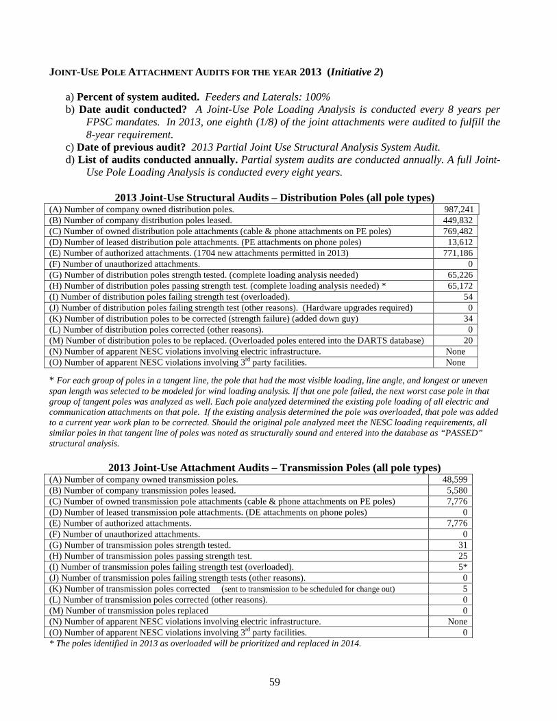
59
JOINT-USE POLE ATTACHMENT AUDITS FOR THE YEAR 2013 (Initiative 2)
a) Percent of system audited. Feeders and Laterals: 100% b) Date audit conducted? A Joint-Use Pole Loading Analysis is conducted every 8 years per
FPSC mandates. In 2013, one eighth (1/8) of the joint attachments were audited to fulfill the 8-year requirement.
c) Date of previous audit? 2013 Partial Joint Use Structural Analysis System Audit. d) List of audits conducted annually. Partial system audits are conducted annually. A full Joint-
Use Pole Loading Analysis is conducted every eight years.
2013 Joint-Use Structural Audits – Distribution Poles (all pole types) (A) Number of company owned distribution poles. 987,241 (B) Number of company distribution poles leased. 449,832 (C) Number of owned distribution pole attachments (cable & phone attachments on PE poles) 769,482 (D) Number of leased distribution pole attachments. (PE attachments on phone poles) 13,612 (E) Number of authorized attachments. (1704 new attachments permitted in 2013) 771,186 (F) Number of unauthorized attachments. 0 (G) Number of distribution poles strength tested. (complete loading analysis needed) 65,226 (H) Number of distribution poles passing strength test. (complete loading analysis needed) * 65,172 (I) Number of distribution poles failing strength test (overloaded). 54 (J) Number of distribution poles failing strength test (other reasons). (Hardware upgrades required) 0 (K) Number of distribution poles to be corrected (strength failure) (added down guy) 34 (L) Number of distribution poles corrected (other reasons). 0 (M) Number of distribution poles to be replaced. (Overloaded poles entered into the DARTS database) 20 (N) Number of apparent NESC violations involving electric infrastructure. None (O) Number of apparent NESC violations involving 3rd party facilities. None
* For each group of poles in a tangent line, the pole that had the most visible loading, line angle, and longest or uneven span length was selected to be modeled for wind loading analysis. If that one pole failed, the next worst case pole in that group of tangent poles was analyzed as well. Each pole analyzed determined the existing pole loading of all electric and communication attachments on that pole. If the existing analysis determined the pole was overloaded, that pole was added to a current year work plan to be corrected. Should the original pole analyzed meet the NESC loading requirements, all similar poles in that tangent line of poles was noted as structurally sound and entered into the database as “PASSED” structural analysis.
2013 Joint-Use Attachment Audits – Transmission Poles (all pole types) (A) Number of company owned transmission poles. 48,599 (B) Number of company transmission poles leased. 5,580 (C) Number of owned transmission pole attachments (cable & phone attachments on PE poles) 7,776 (D) Number of leased transmission pole attachments. (DE attachments on phone poles) 0 (E) Number of authorized attachments. 7,776 (F) Number of unauthorized attachments. 0 (G) Number of transmission poles strength tested. 31 (H) Number of transmission poles passing strength test. 25 (I) Number of transmission poles failing strength test (overloaded). 5* (J) Number of transmission poles failing strength tests (other reasons). 0 (K) Number of transmission poles corrected (sent to transmission to be scheduled for change out) 5 (L) Number of transmission poles corrected (other reasons). 0 (M) Number of transmission poles replaced 0 (N) Number of apparent NESC violations involving electric infrastructure. None (O) Number of apparent NESC violations involving 3rd party facilities. 0 * The poles identified in 2013 as overloaded will be prioritized and replaced in 2014.

60
State whether pole rents are jurisdictional or non-jurisdictional. If pole rents are jurisdictional, then provide an estimate of lost revenue and describe the company’s efforts to minimize the lost revenue. Pole attachment rents are jurisdictional and are booked in Account 454 – “Rent from Electric Property”. DEF conducts partial audits of its pole attachments throughout the year. A full Joint-Use Pole Loading Analysis is conducted every eight years. When DEF discovers unauthorized attachments on DEF poles, DEF follows-up with the attacher who owns the unauthorized attachments and DEF seeks all revenue applicable under controlling laws, rules, and regulations.
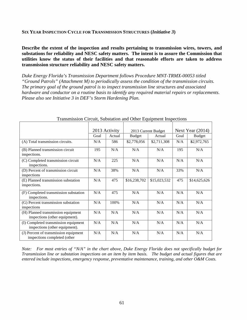
61
SIX YEAR INSPECTION CYCLE FOR TRANSMISSION STRUCTURES (Initiative 3)
Describe the extent of the inspection and results pertaining to transmission wires, towers, and substations for reliability and NESC safety matters. The intent is to assure the Commission that utilities know the status of their facilities and that reasonable efforts are taken to address transmission structure reliability and NESC safety matters.
Duke Energy Florida’s Transmission Department follows Procedure MNT-TRMX-00053 titled “Ground Patrols” (Attachment M) to periodically assess the condition of the transmission circuits. The primary goal of the ground patrol is to inspect transmission line structures and associated hardware and conductor on a routine basis to identify any required material repairs or replacements. Please also see Initiative 3 in DEF’s Storm Hardening Plan.
Transmission Circuit, Substation and Other Equipment Inspections
2013 Activity 2013 Current Budget Next Year (2014) Goal Actual Budget Actual Goal Budget
(A) Total transmission circuits. N/A 586 $2,778,056
$2,711,308 N/A $2,972,765
(B) Planned transmission circuit inspections.
195 N/A N/A N/A 195 N/A
(C) Completed transmission circuit inspections.
N/A 225 N/A N/A N/A N/A
(D) Percent of transmission circuit inspections
N/A 38% N/A N/A 33% N/A
(E) Planned transmission substation inspections.
N/A 475 $16,238,702 $15,023,532 475 $14,625,626
(F) Completed transmission substation inspections.
N/A 475 N/A N/A N/A N/A
(G) Percent transmission substation inspections
N/A 100% N/A N/A N/A N/A
(H) Planned transmission equipment inspections (other equipment).
N/A N/A N/A N/A N/A N/A
(I) Completed transmission equipment inspections (other equipment).
N/A N/A N/A N/A N/A N/A
(J) Percent of transmission equipment inspections completed (other
N/A N/A N/A N/A N/A N/A
Note: For most entries of “N/A” in the chart above, Duke Energy Florida does not specifically budget for Transmission line or substation inspections on an item by item basis. The budget and actual figures that are entered include inspections, emergency response, preventative maintenance, training, and other O&M Costs.
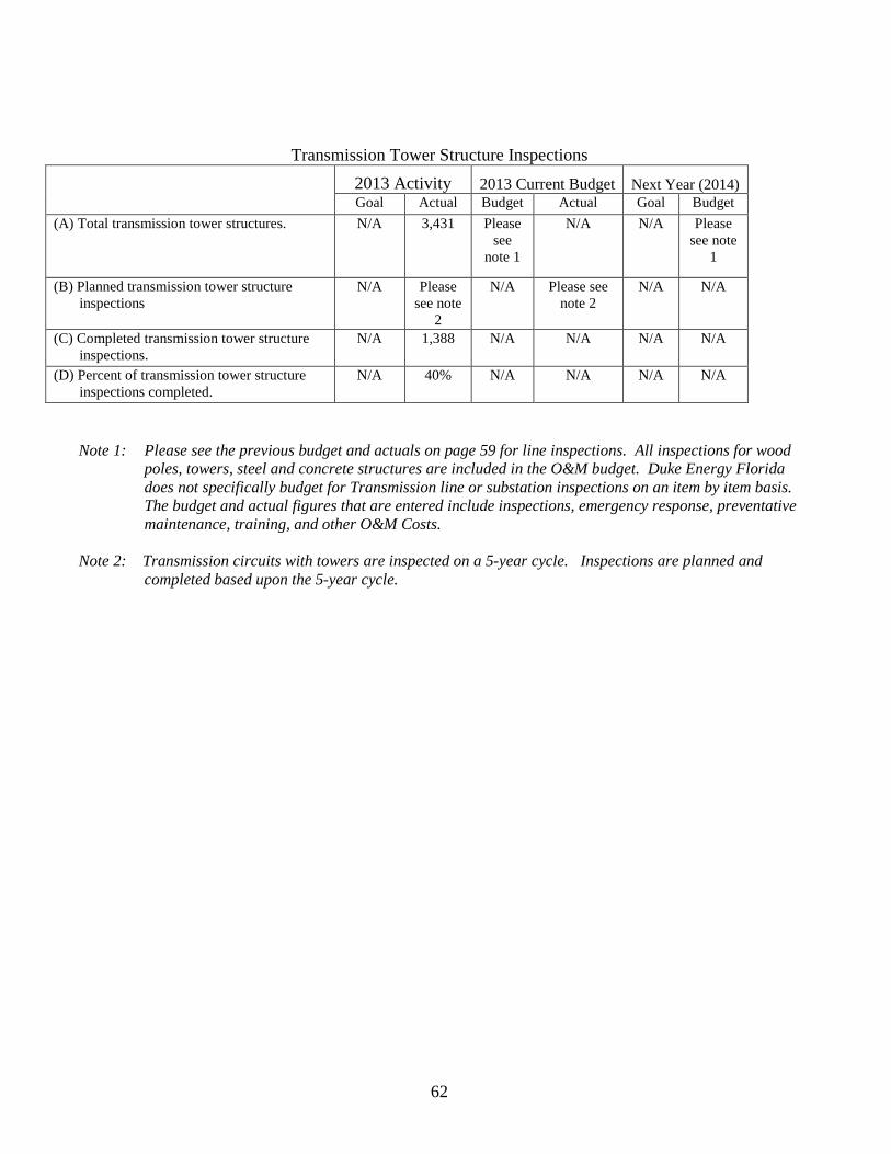
62
Transmission Tower Structure Inspections 2013 Activity 2013 Current Budget Next Year (2014)
Goal Actual Budget Actual Goal Budget (A) Total transmission tower structures. N/A 3,431 Please
see note 1
N/A N/A Please see note
1
(B) Planned transmission tower structure inspections
N/A Please see note
2
N/A Please see note 2
N/A N/A
(C) Completed transmission tower structure inspections.
N/A 1,388 N/A N/A N/A N/A
(D) Percent of transmission tower structure inspections completed.
N/A 40% N/A N/A N/A N/A
Note 1: Please see the previous budget and actuals on page 59 for line inspections. All inspections for wood poles, towers, steel and concrete structures are included in the O&M budget. Duke Energy Florida does not specifically budget for Transmission line or substation inspections on an item by item basis. The budget and actual figures that are entered include inspections, emergency response, preventative maintenance, training, and other O&M Costs.
Note 2: Transmission circuits with towers are inspected on a 5-year cycle. Inspections are planned and
completed based upon the 5-year cycle.
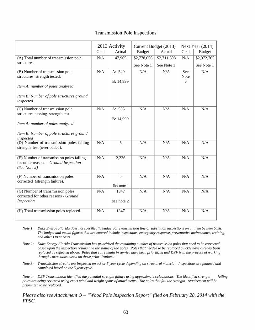
63
Transmission Pole Inspections
2013 Activity Current Budget (2013) Next Year (2014) Goal Actual Budget Actual Goal Budget
(A) Total number of transmission pole structures.
N/A 47,965
$2,778,056
See Note 1
$2,711,308
See Note 1
N/A $2,972,765
See Note 1 (B) Number of transmission pole structures strength tested.
Item A: number of poles analyzed
Item B: Number of pole structures ground inspected
N/A A: 540
B: 14,999
N/A N/A See Note
3
N/A
(C) Number of transmission pole structures passing strength test.
Item A: number of poles analyzed
Item B: Number of pole structures ground inspected
N/A A: 535
B: 14,999
N/A N/A N/A N/A
(D) Number of transmission poles failing strength test (overloaded).
N/A 5 N/A N/A N/A N/A
(E) Number of transmission poles failing for other reasons – Ground Inspection (See Note 2)
N/A 2,236 N/A N/A N/A N/A
(F) Number of transmission poles corrected (strength failure).
N/A 5
See note 4
N/A N/A N/A N/A
(G) Number of transmission poles corrected for other reasons - Ground Inspection
N/A 1347
see note 2
N/A N/A N/A N/A
(H) Total transmission poles replaced. N/A 1347 N/A N/A N/A N/A
Note 1: Duke Energy Florida does not specifically budget for Transmission line or substation inspections on an item by item basis.
The budget and actual figures that are entered include inspections, emergency response, preventative maintenance, training, and other O&M costs.
Note 2: Duke Energy Florida Transmission has prioritized the remaining number of transmission poles that need to be corrected based upon the inspection results and the status of the poles. Poles that needed to be replaced quickly have already been replaced as reflected above. Poles that can remain in service have been prioritized and DEF is in the process of working through corrections based on those prioritizations.
Note 3: Transmission circuits are inspected on a 3 or 5 year cycle depending on structural material. Inspections are planned and completed based on the 5 year cycle.
Note 4: DEF Transmission identified the potential strength failure using approximate calculations. The identified strength failing poles are being reviewed using exact wind and weight spans of attachments. The poles that fail the strength requirement will be prioritized to be replaced.
Please also see Attachment O – “Wood Pole Inspection Report” filed on February 28, 2014 with the FPSC.
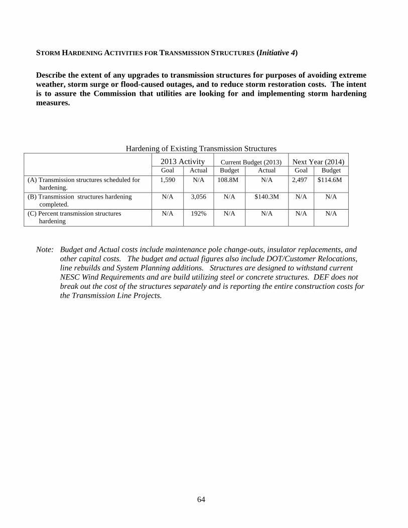
64
STORM HARDENING ACTIVITIES FOR TRANSMISSION STRUCTURES (Initiative 4) Describe the extent of any upgrades to transmission structures for purposes of avoiding extreme weather, storm surge or flood-caused outages, and to reduce storm restoration costs. The intent is to assure the Commission that utilities are looking for and implementing storm hardening measures.
Hardening of Existing Transmission Structures 2013 Activity Current Budget (2013) Next Year (2014)
Goal Actual Budget Actual Goal Budget (A) Transmission structures scheduled for hardening.
1,590 N/A 108.8M N/A 2,497 $114.6M
(B) Transmission structures hardening completed.
N/A 3,056 N/A $140.3M N/A N/A
(C) Percent transmission structures hardening
N/A 192% N/A N/A N/A N/A
Note: Budget and Actual costs include maintenance pole change-outs, insulator replacements, and
other capital costs. The budget and actual figures also include DOT/Customer Relocations, line rebuilds and System Planning additions. Structures are designed to withstand current NESC Wind Requirements and are build utilizing steel or concrete structures. DEF does not break out the cost of the structures separately and is reporting the entire construction costs for the Transmission Line Projects.
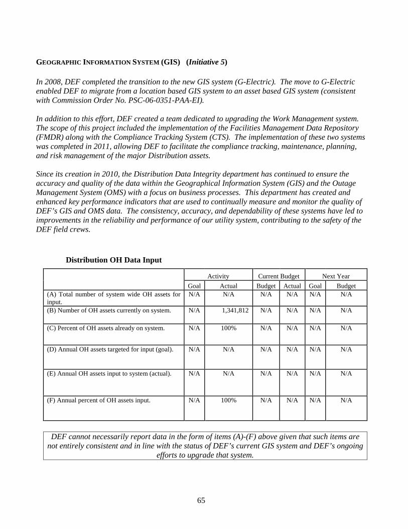
65
GEOGRAPHIC INFORMATION SYSTEM (GIS) (Initiative 5) In 2008, DEF completed the transition to the new GIS system (G-Electric). The move to G-Electric enabled DEF to migrate from a location based GIS system to an asset based GIS system (consistent with Commission Order No. PSC-06-0351-PAA-EI). In addition to this effort, DEF created a team dedicated to upgrading the Work Management system. The scope of this project included the implementation of the Facilities Management Data Repository (FMDR) along with the Compliance Tracking System (CTS). The implementation of these two systems was completed in 2011, allowing DEF to facilitate the compliance tracking, maintenance, planning, and risk management of the major Distribution assets. Since its creation in 2010, the Distribution Data Integrity department has continued to ensure the accuracy and quality of the data within the Geographical Information System (GIS) and the Outage Management System (OMS) with a focus on business processes. This department has created and enhanced key performance indicators that are used to continually measure and monitor the quality of DEF’s GIS and OMS data. The consistency, accuracy, and dependability of these systems have led to improvements in the reliability and performance of our utility system, contributing to the safety of the DEF field crews.
Distribution OH Data Input
Activity Current Budget Next Year
Goal Actual Budget Actual Goal Budget
(A) Total number of system wide OH assets for input.
N/A N/A N/A N/A N/A N/A
(B) Number of OH assets currently on system. N/A 1,341,812 N/A N/A N/A N/A
(C) Percent of OH assets already on system. N/A 100% N/A N/A N/A N/A
(D) Annual OH assets targeted for input (goal). N/A N/A N/A N/A N/A N/A
(E) Annual OH assets input to system (actual). N/A N/A N/A N/A N/A N/A
(F) Annual percent of OH assets input. N/A 100% N/A N/A N/A N/A
DEF cannot necessarily report data in the form of items (A)-(F) above given that such items are not entirely consistent and in line with the status of DEF’s current GIS system and DEF’s ongoing
efforts to upgrade that system.
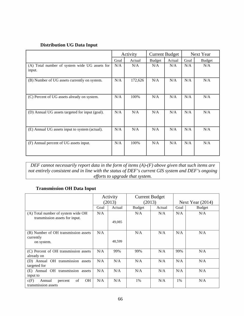
66
Distribution UG Data Input
Activity Current Budget Next Year
Goal Actual Budget Actual Goal Budget
(A) Total number of system wide UG assets for input.
N/A N/A N/A N/A N/A N/A
(B) Number of UG assets currently on system. N/A 172,626 N/A N/A N/A N/A
(C) Percent of UG assets already on system. N/A 100% N/A N/A N/A N/A
(D) Annual UG assets targeted for input (goal). N/A N/A N/A N/A N/A N/A
(E) Annual UG assets input to system (actual). N/A N/A N/A N/A N/A N/A
(F) Annual percent of UG assets input. N/A 100% N/A N/A N/A N/A
DEF cannot necessarily report data in the form of items (A)-(F) above given that such items are not entirely consistent and in line with the status of DEF’s current GIS system and DEF’s ongoing
efforts to upgrade that system.
Transmission OH Data Input Activity
(2013) Current Budget
(2013) Next Year (2014) Goal Actual Budget Actual Goal Budget
(A) Total number of system wide OH transmission assets for input.
N/A
49,085
N/A N/A N/A N/A
(B) Number of OH transmission assets currently on system.
N/A
48,599
N/A N/A N/A N/A
(C) Percent of OH transmission assets already on
N/A 99% 99% N/A 99% N/A
(D) Annual OH transmission assets targeted for
N/A N/A N/A N/A N/A N/A
(E) Annual OH transmission assets input to
N/A N/A N/A N/A N/A N/A
c(F) Annual percent of OH transmission assets
N/A N/A 1% N/A 1% N/A
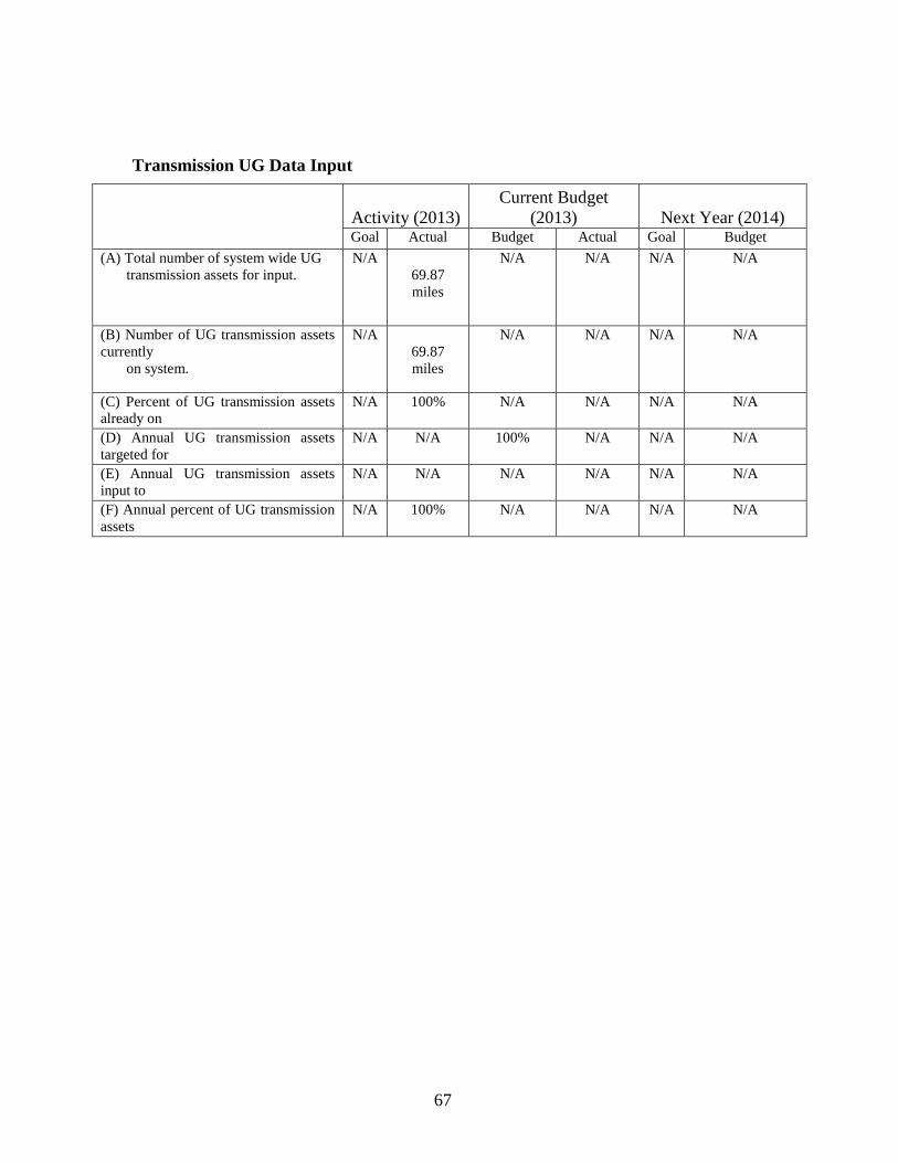
67
Transmission UG Data Input
Activity (2013) Current Budget
(2013) Next Year (2014) Goal Actual Budget Actual Goal Budget
(A) Total number of system wide UG transmission assets for input.
N/A 69.87 miles
N/A N/A N/A N/A
(B) Number of UG transmission assets currently on system.
N/A 69.87 miles
N/A
N/A N/A N/A
(C) Percent of UG transmission assets already on
N/A 100% N/A N/A N/A N/A
(D) Annual UG transmission assets targeted for
N/A N/A 100% N/A N/A N/A
(E) Annual UG transmission assets input to
N/A N/A N/A N/A N/A N/A
(F) Annual percent of UG transmission assets
N/A 100% N/A N/A N/A N/A
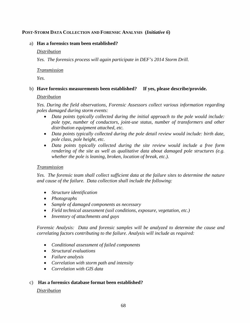
68
POST-STORM DATA COLLECTION AND FORENSIC ANALYSIS (Initiative 6)
a) Has a forensics team been established?
Distribution Yes. The forensics process will again participate in DEF’s 2014 Storm Drill.
Transmission Yes.
b) Have forensics measurements been established? If yes, please describe/provide. Distribution Yes. During the field observations, Forensic Assessors collect various information regarding poles damaged during storm events:
• Data points typically collected during the initial approach to the pole would include: pole type, number of conductors, joint-use status, number of transformers and other distribution equipment attached, etc.
• Data points typically collected during the pole detail review would include: birth date, pole class, pole height, etc.
• Data points typically collected during the site review would include a free form rendering of the site as well as qualitative data about damaged pole structures (e.g. whether the pole is leaning, broken, location of break, etc.).
Transmission
Yes. The forensic team shall collect sufficient data at the failure sites to determine the nature and cause of the failure. Data collection shall include the following:
• Structure identification • Photographs • Sample of damaged components as necessary • Field technical assessment (soil conditions, exposure, vegetation, etc.) • Inventory of attachments and guys
Forensic Analysis: Data and forensic samples will be analyzed to determine the cause and correlating factors contributing to the failure. Analysis will include as required:
• Conditional assessment of failed components • Structural evaluations • Failure analysis • Correlation with storm path and intensity • Correlation with GIS data
c) Has a forensics database format been established?
Distribution
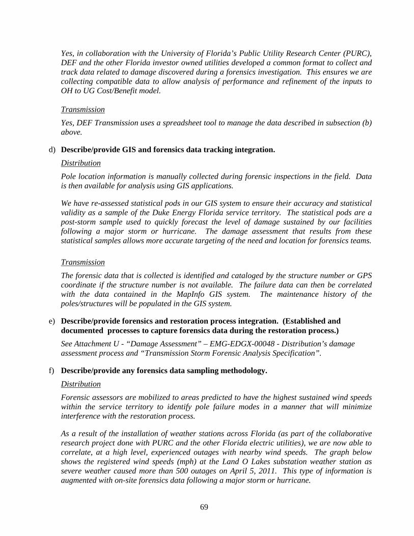
69
Yes, in collaboration with the University of Florida’s Public Utility Research Center (PURC), DEF and the other Florida investor owned utilities developed a common format to collect and track data related to damage discovered during a forensics investigation. This ensures we are collecting compatible data to allow analysis of performance and refinement of the inputs to OH to UG Cost/Benefit model. Transmission
Yes, DEF Transmission uses a spreadsheet tool to manage the data described in subsection (b) above.
d) Describe/provide GIS and forensics data tracking integration. Distribution Pole location information is manually collected during forensic inspections in the field. Data is then available for analysis using GIS applications.
We have re-assessed statistical pods in our GIS system to ensure their accuracy and statistical validity as a sample of the Duke Energy Florida service territory. The statistical pods are a post-storm sample used to quickly forecast the level of damage sustained by our facilities following a major storm or hurricane. The damage assessment that results from these statistical samples allows more accurate targeting of the need and location for forensics teams.
Transmission
The forensic data that is collected is identified and cataloged by the structure number or GPS coordinate if the structure number is not available. The failure data can then be correlated with the data contained in the MapInfo GIS system. The maintenance history of the poles/structures will be populated in the GIS system.
e) Describe/provide forensics and restoration process integration. (Established and documented processes to capture forensics data during the restoration process.)
See Attachment U - “Damage Assessment” – EMG-EDGX-00048 - Distribution’s damage assessment process and “Transmission Storm Forensic Analysis Specification”.
f) Describe/provide any forensics data sampling methodology. Distribution Forensic assessors are mobilized to areas predicted to have the highest sustained wind speeds within the service territory to identify pole failure modes in a manner that will minimize interference with the restoration process.
As a result of the installation of weather stations across Florida (as part of the collaborative research project done with PURC and the other Florida electric utilities), we are now able to correlate, at a high level, experienced outages with nearby wind speeds. The graph below shows the registered wind speeds (mph) at the Land O Lakes substation weather station as severe weather caused more than 500 outages on April 5, 2011. This type of information is augmented with on-site forensics data following a major storm or hurricane.
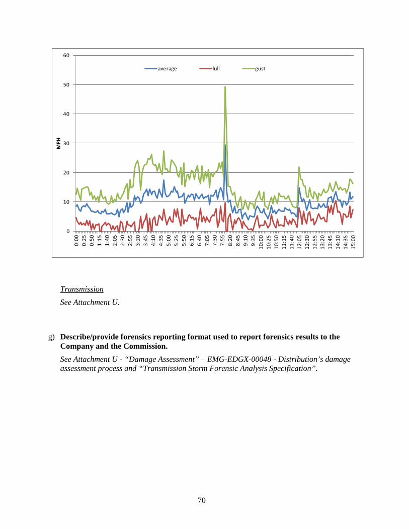
70
0
10
20
30
40
50
60
0:00
0:25
0:50
1:15
1:40
2:05
2:30
2:55
3:20
3:45
4:10
4:35
5:00
5:25
5:50
6:15
6:40
7:05
7:30
7:55
8:20
8:45
9:10
9:35
10:0
010
:25
10:5
011
:15
11:4
012
:05
12:3
012
:55
13:2
013
:45
14:1
014
:35
15:0
0
MPH
average lull gust
Transmission
See Attachment U.
g) Describe/provide forensics reporting format used to report forensics results to the Company and the Commission.
See Attachment U - “Damage Assessment” – EMG-EDGX-00048 - Distribution’s damage assessment process and “Transmission Storm Forensic Analysis Specification”.
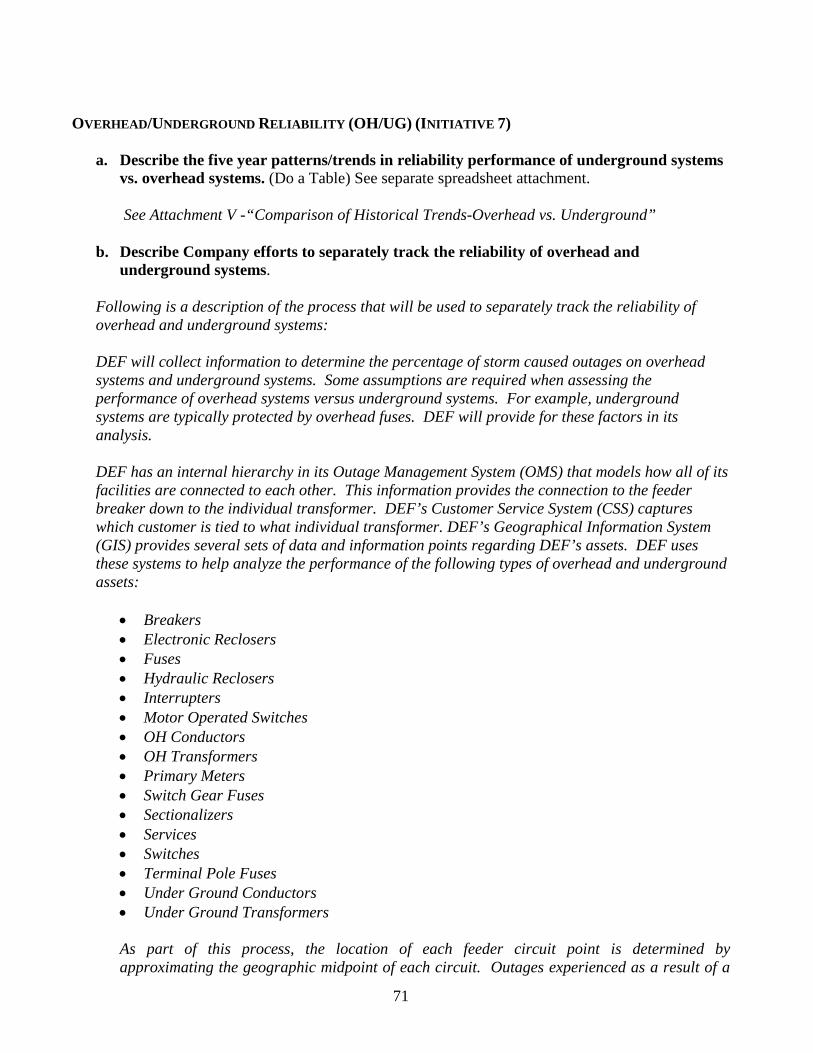
71
OVERHEAD/UNDERGROUND RELIABILITY (OH/UG) (INITIATIVE 7)
a. Describe the five year patterns/trends in reliability performance of underground systems vs. overhead systems. (Do a Table) See separate spreadsheet attachment.
See Attachment V -“Comparison of Historical Trends-Overhead vs. Underground”
b. Describe Company efforts to separately track the reliability of overhead and
underground systems.
Following is a description of the process that will be used to separately track the reliability of overhead and underground systems:
DEF will collect information to determine the percentage of storm caused outages on overhead systems and underground systems. Some assumptions are required when assessing the performance of overhead systems versus underground systems. For example, underground systems are typically protected by overhead fuses. DEF will provide for these factors in its analysis. DEF has an internal hierarchy in its Outage Management System (OMS) that models how all of its facilities are connected to each other. This information provides the connection to the feeder breaker down to the individual transformer. DEF’s Customer Service System (CSS) captures which customer is tied to what individual transformer. DEF’s Geographical Information System (GIS) provides several sets of data and information points regarding DEF’s assets. DEF uses these systems to help analyze the performance of the following types of overhead and underground assets:
• Breakers • Electronic Reclosers • Fuses • Hydraulic Reclosers • Interrupters • Motor Operated Switches • OH Conductors • OH Transformers • Primary Meters • Switch Gear Fuses • Sectionalizers • Services • Switches • Terminal Pole Fuses • Under Ground Conductors • Under Ground Transformers
As part of this process, the location of each feeder circuit point is determined by approximating the geographic midpoint of each circuit. Outages experienced as a result of a
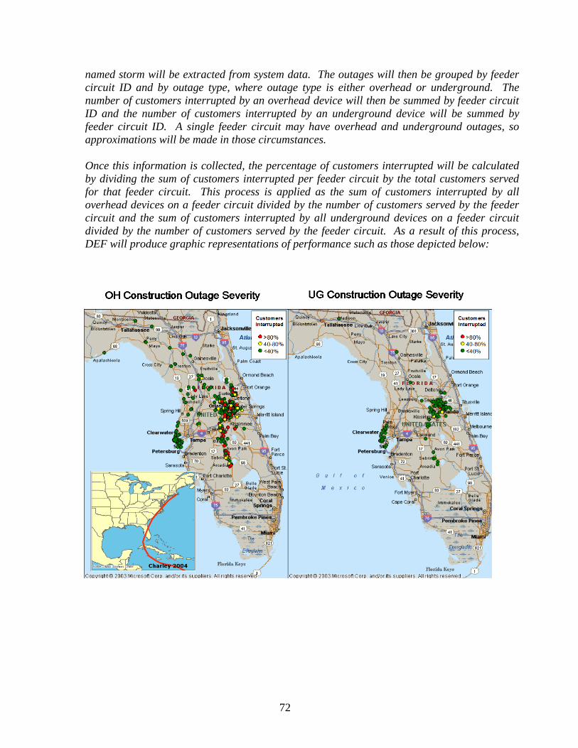
72
named storm will be extracted from system data. The outages will then be grouped by feeder circuit ID and by outage type, where outage type is either overhead or underground. The number of customers interrupted by an overhead device will then be summed by feeder circuit ID and the number of customers interrupted by an underground device will be summed by feeder circuit ID. A single feeder circuit may have overhead and underground outages, so approximations will be made in those circumstances. Once this information is collected, the percentage of customers interrupted will be calculated by dividing the sum of customers interrupted per feeder circuit by the total customers served for that feeder circuit. This process is applied as the sum of customers interrupted by all overhead devices on a feeder circuit divided by the number of customers served by the feeder circuit and the sum of customers interrupted by all underground devices on a feeder circuit divided by the number of customers served by the feeder circuit. As a result of this process, DEF will produce graphic representations of performance such as those depicted below:
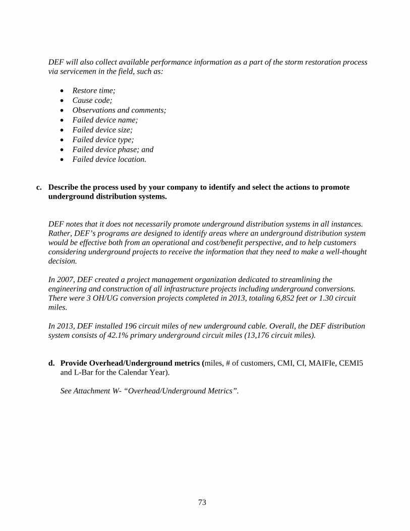
73
DEF will also collect available performance information as a part of the storm restoration process via servicemen in the field, such as:
• Restore time; • Cause code; • Observations and comments; • Failed device name; • Failed device size; • Failed device type; • Failed device phase; and • Failed device location.
c. Describe the process used by your company to identify and select the actions to promote
underground distribution systems.
DEF notes that it does not necessarily promote underground distribution systems in all instances. Rather, DEF’s programs are designed to identify areas where an underground distribution system would be effective both from an operational and cost/benefit perspective, and to help customers considering underground projects to receive the information that they need to make a well-thought decision. In 2007, DEF created a project management organization dedicated to streamlining the engineering and construction of all infrastructure projects including underground conversions. There were 3 OH/UG conversion projects completed in 2013, totaling 6,852 feet or 1.30 circuit miles.
In 2013, DEF installed 196 circuit miles of new underground cable. Overall, the DEF distribution system consists of 42.1% primary underground circuit miles (13,176 circuit miles).
d. Provide Overhead/Underground metrics (miles, # of customers, CMI, CI, MAIFIe, CEMI5
and L-Bar for the Calendar Year).
See Attachment W- “Overhead/Underground Metrics”.
74
COORDINATION WITH LOCAL GOVERNMENTS (Initiative 8) Update on Duke Energy Florida’s (DEF) local government storm response coordination activities: DEF’s storm planning and response program is operational twelve months out of the year and response activities for catastrophic events can be implemented at any time. Currently, there are approximately sixty (60) resources assigned to coordination with local government as part of an emergency planning and response program. Also, approximately forty (40) employees are assigned full-time, year-round, to coordinate with local government on issues such as emergency planning, vegetation management, undergrounding and service related issues. Vegetation Management –Maintaining trees and vegetation along distribution and transmission rights of way helps reduce outages on a day-to-day basis as well as during storm events and enhances safety for customers, as well as DEF employees and contractors. DEF maintains a rigorous inspection process that identifies vegetation encroachments and ensures vegetation-management activities follow required pruning and clearance specifications.
Tree Trimming - To enhance communication with our communities regarding specific tree trimming projects, we meet with municipalities prior to implementation of significant projects in order to inform them of the general areas that are expected to be impacted, note concerns, and answer questions. DEF also conducts communication and outreach to customers along the impacted areas for significant activities to inform them of the project, as well as explain the need for vegetation management. Tree Line USA – In 2013, DEF achieved the designation of “Tree Line USA Utility.” This designation is given by the National Arbor Day Foundation, in cooperation with the National Association of State Foresters. It recognizes public and private utilities across the nation that demonstrate practices that protect and enhance community forests while managing the need for reliable electric power. This is the seventh consecutive year DEF has received the Tree Line USA designation. Undergrounding – DEF works with communities to inform them of available undergrounding options and to be a part of their planning processes. This assists them in several ways – better fiscal planning, coordination with other utilities, and improved communications with residents affected. Currently, DEF is working with cities along the beaches in Pinellas County in response to a multi-year plan by the communities to underground utilities along Gulf Boulevard, as well as enhance streetscapes and improve pedestrian safety. The construction will be done in increments and is anticipated to be completed in 8-10 years. Other Construction Projects – In addition to undergrounding conversion projects, there are planned transmission and distribution enhancement projects that are expected to result in improvements to system reliability during storm events. DEF works extensively with local governments and communities to coordinate such projects. Emergency Planning and Coordination – DEF’s team works with counties and municipalities year round and during catastrophic events. Prior to storm season, DEF holds meetings with communities to discuss emergency planning preparations and coordination, participates in county drills and training exercises, and holds community education workshops and events.
75
As part of our yearly planning process, we work with counties to identify and prioritize specific infrastructure within the counties. This prioritization of accounts is factored into restoration activities by our operation centers during storms.
We have developed our capability to produce detailed electronic outage information which is provided to county Emergency Operations Centers (EOCs) throughout storm events. The information is available in multiple formats, including formats that may be imported into county GIS systems. This program provides significant information to EOCs during storms to assist in their response efforts. Information includes detailed outage data per each square mile within the county and is produced periodically during each day of a significant catastrophic event. DEF has modified its program to make this detailed outage data available to counties during mid-level storm events as well.
In 2013, DEF developed a “Make it Safe” road clearing program to provide dedicated resources to assist selected counties in our service territories for the first 24 – 48 hours of storm restoration with road clearing and “make it safe” activities. DEF will have dedicated contract crews for each zone staged at county facilities or DEF operations centers. The benefits of this program include improved response time to county priorities, improve customer satisfaction by reducing customer outage time, reduce exposure to night time storm hazards, and increase DEF crew productivity during daylight hours.
Additionally, DEF has developed live line demonstrations, called “Arc and Spark,” which include critical information for first responders and emergency management personnel. DEF’s team of experts will recreate live-voltage scenarios such as downed power lines, trees and/or ladders on power lines, vehicle wrecks involving power lines, and digging into underground facilities incidents. DEF shares this information with city, county and emergency personnel to assist them in planning and safety instruction.
2013 Activities
The following activities are not an exhaustive list, but include many of the activities associated with Duke Energy Florida’s coordination activities with state and local governments for 2013:
• Emergency Operation Center visits were performed in Alachua, Bay, Citrus, Columbia, Franklin, Gadsden, Gilchrist, Gulf, Hamilton, Hardee, Hernando, Highlands, Jefferson, Lafayette, Lake, Liberty, Leon, Levy, Madison, Marion, Orange, Osceola, Pasco, Pinellas, Polk, Seminole, Sumter, Suwannee, Taylor, Volusia and Wakulla counties at the EOCs and EOC exercises to review storm procedures prior to storm season. (February – June 2013)
• Florida Statewide Hurricane Exercise - Representatives throughout the DEF service territory participated in storm preparedness activities throughout this event. (May 2013)
• Seminole County Emergency Operations Center Table Top Exercise – DEF participated in a mock-drill for the pre-storm, during and post-storm stages of emergency response. (May 2013)
76
• Orange County - First responders from the cities of Belle Isle, Edgewood, Winter Garden, Ocoee, Windermere and Oakland were invited to participate in the Live Wire Demonstrations at DEF’s Southeast Orlando and Winter Garden operating centers. (May and June 2013)
• Marion County – DEF participated in a training session at the EOC for utility workers and first responders. (August 2013)
• Pinellas County – DEF held two training and education sessions with fire and police chiefs, city
managers and mayors at the DEF Energy Control Center to review DEF’s storm processes and provided a tour of our outage restoration process. (June 2013)
• Seminole County - All Seminole County municipalities were invited to a demonstration hosted by the DEF Community Relations Manager and the DEF Apopka operations center. DEF demonstrated the "live truck" to first responders and public works representatives from Seminole County and local municipalities. (June 2013)
• Polk County Hurricane Expo – Duke Energy hosted a booth where DEF had the opportunity to
speak to families about products, services, weather and hurricane readiness. (June 2013)
• Pasco County Arc & Spark Session – This training session was held with members of Pasco County Fire & Rescue, New Port Richey and Port Richey Police and Fire Departments, as well as Traffic Operations in Pasco County to show the dangers of high voltages. More than forty (40) people attended the training session. (October 2013)
• A Duke EOC Representative met with the Volusia County EOC to draft the EOC training calendar
for 2014. (November 2013)
2014 Activities The following activities are currently planned activities associated with Duke Energy’s coordination activities with state and local governments for 2014: State Activities:
• Florida's Severe Weather Awareness Week (February 24 - 28, 2014)
• 28th Annual Governor’s Hurricane Conference (May 11 – 16, 2014 )
• Florida Annual Statewide Hurricane Exercise (May 19 - 22, 2014)
• Governor's Annual Domestic Security Executive Exercise (TBD)
2014 County/City Activities:
77
• DEF representatives will meet with county representatives in each of our counties throughout our service territory during the year as well as participate in pre-storm season planning activities such as mock drills at the County EOCs. These meetings and visits will also include updating the EOCs on DEF emergency response policies and DEF website demonstrations on how to access electronic outage information during storm events. Some examples are provided below.
o DEF conducts ongoing communications with municipalities to provide information about DEF’s emergency response planning, respond to inquiries, and to update county contact information for all EOCs.
o DEF executives will meet with many of the county EOC directors and their staff to discuss DEF’s storm response planning and enhancement of the coordination between the company and county emergency management.
• DEF will meet with school board superintendents and their staff to discuss storm coordination, restoration prioritization, shelter locations and back-up generation availability.
• DEF will participate in many community hurricane and storm expos held by counties or federal or state agencies throughout our service territory and beyond, to inform the public and encourage appropriate storm preparation by residents and business.
• DEF has developed a partnership with the Council of Neighborhood Associations (CONA) in South Pinellas County that provides opportunities to communicate to more than 110 HOAs through articles in their monthly newsletters. We also meet with many other HOAs and POAs throughout the DEF service territory. We use these opportunities to inform the residents of storm preparation activities and provide information prior to storm season.
• DEF is working with the Pinellas County barrier island communities that have expressed a strong interest in undergrounding with the assistance of county funds for these infrastructure projects.
• DEF conducts an internal week-long storm preparedness training prior to storm season to simulate the response to a real storm including pre-storm preparations activities during a major storm event and post-storm response. During this exercise, the county EOCs are engaged as part of the simulation.
• DEF has created a webpage with an interactive map that is available to the public, including the media and local governments. The interactive map provides access to the latest outage information twenty-four hours a day, seven days a week. These maps provide county-specific estimates for power restoration when available and the ability to search by address.
• DEF has developed a system to report outages online via computer or other mobile device. This online reporting tool gives our customers another way to communicate with DEF, helping ensure any disruptions in service are recognized immediately and that power is restored as quickly and safely as possible.
• DEF has added four state-of-the-art mobile command centers. Each of these electric generator powered mobile command centers is equipped with work stations, satellite phones and internet capabilities and will be stationed in the hardest hit areas following a major storm event. These

78
mobile command centers will act as self-sufficient emergency command posts, giving DEF the ability to respond more quickly to isolated or severely damaged areas. The units will also serve as individual processing locations allowing field supervisors to effectively manage the flow of the thousands of employees from numerous utilities responding to a single staging site following a storm.
79
COLLABORATIVE RESEARCH (Initiative 9) Project Planning Report: For each project identified by the Steering Committee, provide a report that includes the purpose, scope, objectives, research method, data inputs, expected costs and benefits, sources of funding, schedule, and findings to date.
Please see Attachment X - “PURC Report on Collaborative Research for Hurricane Hardening” dated February 2014.
Annual Progress Report: For each project previously identified by the Steering Committee for which ongoing research is being pursued but not completed, provide an annual report, including updates on all aspects of the Project Planning Report.
Please see Attachment X - “PURC Report on Collaborative Research for Hurricane Hardening” dated February 2014.
Project Completion Summary Report: For each concluded project identified by the Steering Committee, provide a report that includes an assessment of the success of the research project, as well as any proposed implementation plan for any results or findings for each utility. Describe the benefits expected or realized as a result of plan implementation on storm hardening for each utility.
Please see Attachment X - “PURC Report on Collaborative Research for Hurricane Hardening” dated February 2014.
Annual Report of the Collaborative Research Effort: Provide a report to include an overall assessment of the collaborative research program to date, as described in the Memorandum of Understanding (MOU) dated January 1, 2010, including its operational and financial viability and future planning of the organization. Identify any extension of the MOU contemplated or finalized by the Steering Committee.
Please see Attachment X - “PURC Report on Collaborative Research for Hurricane Hardening” dated February 2014.
Describe the projects promoted, costs incurred, and benefits achieved. A single joint filing can address all collaborative research. Utilities should also discuss any additional independent activities in which it is engaged, such as EPRI, private research, or through universities.
Please see Attachment X - “PURC Report on Collaborative Research for Hurricane Hardening dated February 2014. In addition to DEF’s involvement with PURC, DEF is actively engaged as both participant and presenter in a variety of technical and professional organizations where hardening alternatives are reviewed and assessed. Examples include the Southeastern Electric Exchange (SEE), Edison Electric Institute (EEI), Institute of Electrical and Electronics Engineers (IEEE), Chartwell Hardening Teleconference, and Davies Consulting Asset Management Conference. DEF Standards engineers also assess new products on a continuous basis.

80
DISASTER PREPAREDNESS AND RECOVERY PLAN (Initiative 10)
Submit formal disaster preparedness plan annually by March 1st. Include disaster recovery training completed, pre-storm preparation and staging activities, post storm recovery plans, lessons learned, and plan modifications or changes.
Duke Energy has an established storm recovery plan that is reviewed and updated annually based on lessons learned from the previous storm season and organizational needs.
For Distribution - See Attachment Y – “Distribution System Storm Operational Plan (DSSOP).
For Transmission – See Attachment Z – “Transmission Storm Plan”.
81
VI. Other Storm Hardening Initiatives (OH/UG)
a. For each of the other ongoing storm hardening initiatives provide a detailed discussion describing the activity and costs incurred for 2013 and projected for 2014.
Please see DEF’s Storm Hardening Plan – Attachment J. Also, please see response on page 43.
b. Overhead/Underground i. Describe the process used by your company to identify the scope of storm
hardening projects. ii. Provide any quantified expected benefits.
iii. If benefit quantification is not practical or possible at this time, explain when or how the cost-effectiveness of the activity is assessed.
Please see DEF’s Storm Hardening Plan – Attachment J. Also, please see response on page 43.

ATTACHMENT A
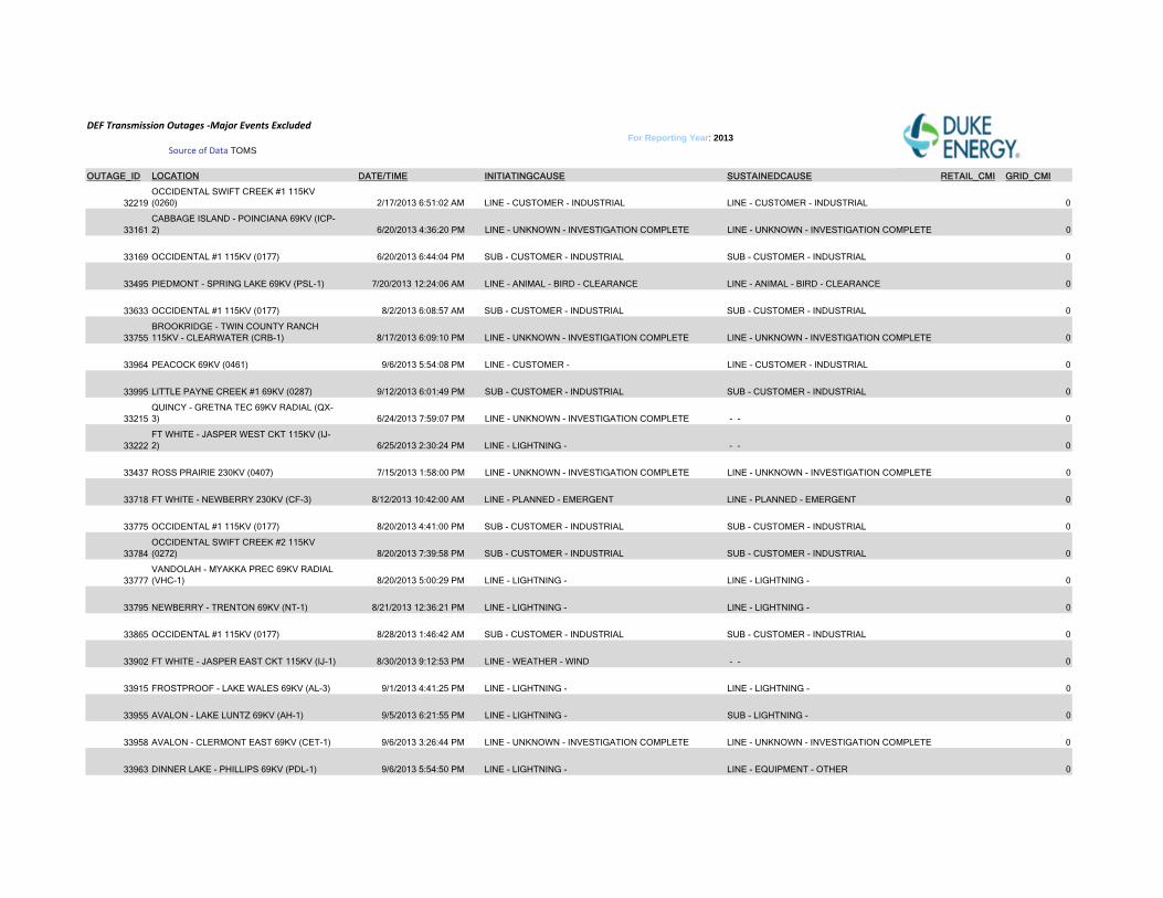
DEF Transmission Outages ‐Major Events Excluded
OUTAGE_ID LOCATION DATE/TIME INITIATINGCAUSE SUSTAINEDCAUSE RETAIL_CMI GRID_CMI
32219OCCIDENTAL SWIFT CREEK #1 115KV (0260) 2/17/2013 6:51:02 AM LINE - CUSTOMER - INDUSTRIAL LINE - CUSTOMER - INDUSTRIAL 0
33161CABBAGE ISLAND - POINCIANA 69KV (ICP-2) 6/20/2013 4:36:20 PM LINE - UNKNOWN - INVESTIGATION COMPLETE LINE - UNKNOWN - INVESTIGATION COMPLETE 0
33169 OCCIDENTAL #1 115KV (0177) 6/20/2013 6:44:04 PM SUB - CUSTOMER - INDUSTRIAL SUB - CUSTOMER - INDUSTRIAL 0
33495 PIEDMONT - SPRING LAKE 69KV (PSL-1) 7/20/2013 12:24:06 AM LINE - ANIMAL - BIRD - CLEARANCE LINE - ANIMAL - BIRD - CLEARANCE 0
33633 OCCIDENTAL #1 115KV (0177) 8/2/2013 6:08:57 AM SUB - CUSTOMER - INDUSTRIAL SUB - CUSTOMER - INDUSTRIAL 0
33755BROOKRIDGE - TWIN COUNTY RANCH 115KV - CLEARWATER (CRB-1) 8/17/2013 6:09:10 PM LINE - UNKNOWN - INVESTIGATION COMPLETE LINE - UNKNOWN - INVESTIGATION COMPLETE 0
33964 PEACOCK 69KV (0461) 9/6/2013 5:54:08 PM LINE - CUSTOMER - LINE - CUSTOMER - INDUSTRIAL 0
33995 LITTLE PAYNE CREEK #1 69KV (0287) 9/12/2013 6:01:49 PM SUB - CUSTOMER - INDUSTRIAL SUB - CUSTOMER - INDUSTRIAL 0
33215QUINCY - GRETNA TEC 69KV RADIAL (QX-3) 6/24/2013 7:59:07 PM LINE - UNKNOWN - INVESTIGATION COMPLETE - - 0
33222FT WHITE - JASPER WEST CKT 115KV (IJ-2) 6/25/2013 2:30:24 PM LINE - LIGHTNING - - - 0
33437 ROSS PRAIRIE 230KV (0407) 7/15/2013 1:58:00 PM LINE - UNKNOWN - INVESTIGATION COMPLETE LINE - UNKNOWN - INVESTIGATION COMPLETE 0
33718 FT WHITE - NEWBERRY 230KV (CF-3) 8/12/2013 10:42:00 AM LINE - PLANNED - EMERGENT LINE - PLANNED - EMERGENT 0
33775 OCCIDENTAL #1 115KV (0177) 8/20/2013 4:41:00 PM SUB - CUSTOMER - INDUSTRIAL SUB - CUSTOMER - INDUSTRIAL 0
33784OCCIDENTAL SWIFT CREEK #2 115KV (0272) 8/20/2013 7:39:58 PM SUB - CUSTOMER - INDUSTRIAL SUB - CUSTOMER - INDUSTRIAL 0
33777VANDOLAH - MYAKKA PREC 69KV RADIAL (VHC-1) 8/20/2013 5:00:29 PM LINE - LIGHTNING - LINE - LIGHTNING - 0
33795 NEWBERRY - TRENTON 69KV (NT-1) 8/21/2013 12:36:21 PM LINE - LIGHTNING - LINE - LIGHTNING - 0
33865 OCCIDENTAL #1 115KV (0177) 8/28/2013 1:46:42 AM SUB - CUSTOMER - INDUSTRIAL SUB - CUSTOMER - INDUSTRIAL 0
33902 FT WHITE - JASPER EAST CKT 115KV (IJ-1) 8/30/2013 9:12:53 PM LINE - WEATHER - WIND - - 0
33915 FROSTPROOF - LAKE WALES 69KV (AL-3) 9/1/2013 4:41:25 PM LINE - LIGHTNING - LINE - LIGHTNING - 0
33955 AVALON - LAKE LUNTZ 69KV (AH-1) 9/5/2013 6:21:55 PM LINE - LIGHTNING - SUB - LIGHTNING - 0
33958 AVALON - CLERMONT EAST 69KV (CET-1) 9/6/2013 3:26:44 PM LINE - UNKNOWN - INVESTIGATION COMPLETE LINE - UNKNOWN - INVESTIGATION COMPLETE 0
33963 DINNER LAKE - PHILLIPS 69KV (PDL-1) 9/6/2013 5:54:50 PM LINE - LIGHTNING - LINE - EQUIPMENT - OTHER 0
Source of Data TOMSFor Reporting Year: 2013
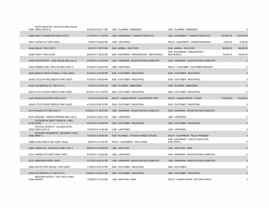
33981NORTH BARTOW - SOUTH ELOISE (TECO) 230KV (WLXT-2) 9/10/2013 6:25:11 AM LINE - PLANNED - EMERGENT LINE - PLANNED - EMERGENT 0
33998 EAST CLEARWATER 230KV (0127) 7/17/2013 4:17:00 PM LINE - EQUIPMENT - CONDUCTOR/STATIC LINE - EQUIPMENT - CONDUCTOR/STATIC 247,947.00 247,947.00
34001 CROSS CITY 69KV (0081) 7/9/2013 5:08:00 PM LINE - LIGHTNING - RELAY - EQUIPMENT - UNDERFREQUENCY 4,300.00 4,300.00
34004 INGLIS 115KV (0037) 8/1/2013 1:59:37 AM SUB - ANIMAL - RACCOON SUB - ANIMAL - RACCOON 98,952.00 98,952.00
34029 VINOY 115KV (0159) 8/25/2013 7:38:38 AM SUB - EQUIPMENT - BREAKER/DIST - MECHANICALSUB - EQUIPMENT - BREAKER/DIST - MECHANICAL 76,400.00 76,400.00
34032 FROSTPROOF - LAKE WALES 69KV (AL-3) 9/15/2013 3:42:34 PM LINE - UNKNOWN - INVESTIGATION COMPLETE LINE - UNKNOWN - INVESTIGATION COMPLETE 0
34034 DINNER LAKE - PHILLIPS 69KV (PDL-1) 9/15/2013 3:46:02 PM LINE - LIGHTNING - RELAY - CUSTOMER - CUSTOMER REQUEST 0
34035 MANLEY ROAD (CARGILL) 115KV (0004) 9/15/2013 3:45:48 PM SUB - CUSTOMER - INDUSTRIAL SUB - CUSTOMER - INDUSTRIAL 0
34036 LITTLE PAYNE CREEK #1 69KV (0287) 9/15/2013 3:56:06 PM SUB - CUSTOMER - INDUSTRIAL SUB - CUSTOMER - INDUSTRIAL 0
32163 OCCIDENTAL #1 115KV (0177) 2/1/2013 9:33:05 AM LINE - PLANNED - EMERGENT LINE - PLANNED - EMERGENT 0
32419 LITTLE PAYNE CREEK #1 69KV (0287) 3/21/2013 12:11:53 PM SUB - CUSTOMER - INDUSTRIAL SUB - CUSTOMER - INDUSTRIAL 0
32472 MAGNOLIA RANCH 69KV (0377) 3/7/2013 8:22:56 AM RELAY - HUMAN ERROR - INADVERTENT TRIP RELAY - HUMAN ERROR - OTHER 172,692.00 172,692.00
32556 LITTLE PAYNE CREEK #1 69KV (0287) 4/11/2013 6:08:19 PM SUB - CUSTOMER - INDUSTRIAL SUB - CUSTOMER - INDUSTRIAL 0
33119 HAINES CITY 69KV (0317) 6/16/2013 11:39:37 PM LINE - UNKNOWN - INVESTIGATION COMPLETE SUB - UNKNOWN - INVESTIGATION COMPLETE 0
33191 DENHAM - TARPON SPRINGS 69KV (TZ-2) 6/22/2013 5:59:01 PM LINE - LIGHTNING - LINE - LIGHTNING - 0
33193OCCIDENTAL SWIFT CREEK #1 115KV (0260) 6/22/2013 6:18:06 PM SUB - CUSTOMER - INDUSTRIAL SUB - CUSTOMER - INDUSTRIAL 0
33530CRYSTAL RIVER PL - HOLDER CKT#1 230KV (CCF-4) 7/23/2013 8:13:38 AM LINE - LIGHTNING - LINE - LIGHTNING - 0
33592BAYBORO PEAKERS PL - BAYBORO 115KV (BPB-1) 7/30/2013 4:39:48 AM SUB - PLANNED - OTHER PLANNED OUTAGE RELAY - EQUIPMENT - RELAY PROBLEM 0
33688 AVON PARK PLANT 230KV (0503) 8/8/2013 4:31:28 PM RELAY - EQUIPMENT - RECLOSINGSUB - EQUIPMENT - CIRCUIT SWITCHER - ELECTRICAL 0
33846 VANDOLAH - WAUCHULA 69KV (VW-1) 8/25/2013 3:18:05 PM LINE - WEATHER - LINE - WEATHER - WIND 0
33121 HAINES CITY EAST 230KV (0497) 6/17/2013 1:02:26 AM LINE - LIGHTNING - SUB - UNKNOWN - INVESTIGATION COMPLETE 0
33131 ANDERSEN 230KV (0245) 6/17/2013 2:04:23 PM LINE - UNKNOWN - INVESTIGATION COMPLETE LINE - UNKNOWN - INVESTIGATION COMPLETE 0
33490 SOUTH FORT MEADE 115KV (0360) 7/19/2013 6:33:15 PM SUB - CUSTOMER - INDUSTRIAL SUB - CUSTOMER - 0
33538 OCCIDENTAL #1 115KV (0177) 7/24/2013 10:43:01 AM SUB - CUSTOMER - INDUSTRIAL SUB - CUSTOMER - INDUSTRIAL 0
33549MEADWDS SOUTH - TAFT (OUC) 230KV (MDWS) 7/25/2013 7:10:25 AM LINE - WEATHER - WIND RELAY - HUMAN ERROR - SETTING ERROR 0
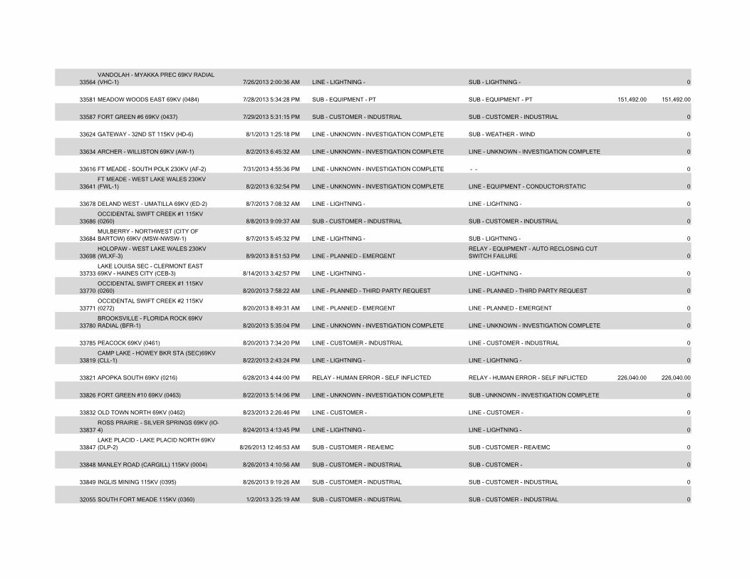
33564VANDOLAH - MYAKKA PREC 69KV RADIAL (VHC-1) 7/26/2013 2:00:36 AM LINE - LIGHTNING - SUB - LIGHTNING - 0
33581 MEADOW WOODS EAST 69KV (0484) 7/28/2013 5:34:28 PM SUB - EQUIPMENT - PT SUB - EQUIPMENT - PT 151,492.00 151,492.00
33587 FORT GREEN #6 69KV (0437) 7/29/2013 5:31:15 PM SUB - CUSTOMER - INDUSTRIAL SUB - CUSTOMER - INDUSTRIAL 0
33624 GATEWAY - 32ND ST 115KV (HD-6) 8/1/2013 1:25:18 PM LINE - UNKNOWN - INVESTIGATION COMPLETE SUB - WEATHER - WIND 0
33634 ARCHER - WILLISTON 69KV (AW-1) 8/2/2013 6:45:32 AM LINE - UNKNOWN - INVESTIGATION COMPLETE LINE - UNKNOWN - INVESTIGATION COMPLETE 0
33616 FT MEADE - SOUTH POLK 230KV (AF-2) 7/31/2013 4:55:36 PM LINE - UNKNOWN - INVESTIGATION COMPLETE - - 0
33641FT MEADE - WEST LAKE WALES 230KV (FWL-1) 8/2/2013 6:32:54 PM LINE - UNKNOWN - INVESTIGATION COMPLETE LINE - EQUIPMENT - CONDUCTOR/STATIC 0
33678 DELAND WEST - UMATILLA 69KV (ED-2) 8/7/2013 7:08:32 AM LINE - LIGHTNING - LINE - LIGHTNING - 0
33686OCCIDENTAL SWIFT CREEK #1 115KV (0260) 8/8/2013 9:09:37 AM SUB - CUSTOMER - INDUSTRIAL SUB - CUSTOMER - INDUSTRIAL 0
33684MULBERRY - NORTHWEST (CITY OF BARTOW) 69KV (MSW-NWSW-1) 8/7/2013 5:45:32 PM LINE - LIGHTNING - SUB - LIGHTNING - 0
33698HOLOPAW - WEST LAKE WALES 230KV (WLXF-3) 8/9/2013 8:51:53 PM LINE - PLANNED - EMERGENT
RELAY - EQUIPMENT - AUTO RECLOSING CUT SWITCH FAILURE 0
33733LAKE LOUISA SEC - CLERMONT EAST 69KV - HAINES CITY (CEB-3) 8/14/2013 3:42:57 PM LINE - LIGHTNING - LINE - LIGHTNING - 0
33770OCCIDENTAL SWIFT CREEK #1 115KV (0260) 8/20/2013 7:58:22 AM LINE - PLANNED - THIRD PARTY REQUEST LINE - PLANNED - THIRD PARTY REQUEST 0
33771OCCIDENTAL SWIFT CREEK #2 115KV (0272) 8/20/2013 8:49:31 AM LINE - PLANNED - EMERGENT LINE - PLANNED - EMERGENT 0
33780BROOKSVILLE - FLORIDA ROCK 69KV RADIAL (BFR-1) 8/20/2013 5:35:04 PM LINE - UNKNOWN - INVESTIGATION COMPLETE LINE - UNKNOWN - INVESTIGATION COMPLETE 0
33785 PEACOCK 69KV (0461) 8/20/2013 7:34:20 PM LINE - CUSTOMER - INDUSTRIAL LINE - CUSTOMER - INDUSTRIAL 0
33819CAMP LAKE - HOWEY BKR STA (SEC)69KV (CLL-1) 8/22/2013 2:43:24 PM LINE - LIGHTNING - LINE - LIGHTNING - 0
33821 APOPKA SOUTH 69KV (0216) 6/28/2013 4:44:00 PM RELAY - HUMAN ERROR - SELF INFLICTED RELAY - HUMAN ERROR - SELF INFLICTED 226,040.00 226,040.00
33826 FORT GREEN #10 69KV (0463) 8/22/2013 5:14:06 PM LINE - UNKNOWN - INVESTIGATION COMPLETE SUB - UNKNOWN - INVESTIGATION COMPLETE 0
33832 OLD TOWN NORTH 69KV (0462) 8/23/2013 2:26:46 PM LINE - CUSTOMER - LINE - CUSTOMER - 0
33837ROSS PRAIRIE - SILVER SPRINGS 69KV (IO-4) 8/24/2013 4:13:45 PM LINE - LIGHTNING - LINE - LIGHTNING - 0
33847LAKE PLACID - LAKE PLACID NORTH 69KV (DLP-2) 8/26/2013 12:46:53 AM SUB - CUSTOMER - REA/EMC SUB - CUSTOMER - REA/EMC 0
33848 MANLEY ROAD (CARGILL) 115KV (0004) 8/26/2013 4:10:56 AM SUB - CUSTOMER - INDUSTRIAL SUB - CUSTOMER - 0
33849 INGLIS MINING 115KV (0395) 8/26/2013 9:19:26 AM SUB - CUSTOMER - INDUSTRIAL SUB - CUSTOMER - INDUSTRIAL 0
32055 SOUTH FORT MEADE 115KV (0360) 1/2/2013 3:25:19 AM SUB - CUSTOMER - INDUSTRIAL SUB - CUSTOMER - INDUSTRIAL 0
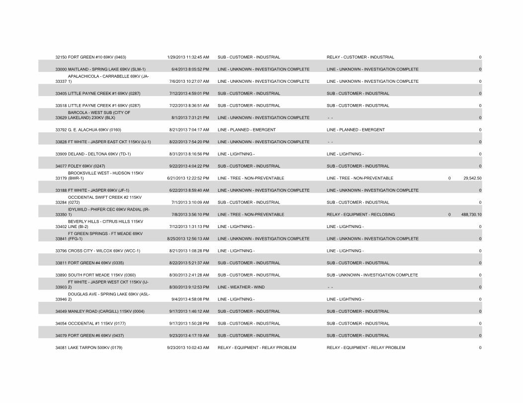
32150 FORT GREEN #10 69KV (0463) 1/29/2013 11:32:45 AM SUB - CUSTOMER - INDUSTRIAL RELAY - CUSTOMER - INDUSTRIAL 0
33000 MAITLAND - SPRING LAKE 69KV (SLM-1) 6/4/2013 8:05:52 PM LINE - UNKNOWN - INVESTIGATION COMPLETE LINE - UNKNOWN - INVESTIGATION COMPLETE 0
33337APALACHICOLA - CARRABELLE 69KV (JA-1) 7/6/2013 10:27:07 AM LINE - UNKNOWN - INVESTIGATION COMPLETE LINE - UNKNOWN - INVESTIGATION COMPLETE 0
33405 LITTLE PAYNE CREEK #1 69KV (0287) 7/12/2013 4:59:01 PM SUB - CUSTOMER - INDUSTRIAL SUB - CUSTOMER - INDUSTRIAL 0
33518 LITTLE PAYNE CREEK #1 69KV (0287) 7/22/2013 8:36:51 AM SUB - CUSTOMER - INDUSTRIAL SUB - CUSTOMER - INDUSTRIAL 0
33629BARCOLA - WEST SUB (CITY OF LAKELAND) 230KV (BLX) 8/1/2013 7:31:21 PM LINE - UNKNOWN - INVESTIGATION COMPLETE - - 0
33792 G. E. ALACHUA 69KV (0160) 8/21/2013 7:04:17 AM LINE - PLANNED - EMERGENT LINE - PLANNED - EMERGENT 0
33828 FT WHITE - JASPER EAST CKT 115KV (IJ-1) 8/22/2013 7:54:20 PM LINE - UNKNOWN - INVESTIGATION COMPLETE - - 0
33909 DELAND - DELTONA 69KV (TD-1) 8/31/2013 8:16:56 PM LINE - LIGHTNING - LINE - LIGHTNING - 0
34077 FOLEY 69KV (0247) 9/22/2013 4:04:22 PM SUB - CUSTOMER - INDUSTRIAL SUB - CUSTOMER - INDUSTRIAL 0
33179BROOKSVILLE WEST - HUDSON 115KV (BWR-1) 6/21/2013 12:22:52 PM LINE - TREE - NON-PREVENTABLE LINE - TREE - NON-PREVENTABLE 0 29,542.50
33188 FT WHITE - JASPER 69KV (JF-1) 6/22/2013 8:59:40 AM LINE - UNKNOWN - INVESTIGATION COMPLETE LINE - UNKNOWN - INVESTIGATION COMPLETE 0
33284OCCIDENTAL SWIFT CREEK #2 115KV (0272) 7/1/2013 3:10:09 AM SUB - CUSTOMER - INDUSTRIAL SUB - CUSTOMER - INDUSTRIAL 0
33350IDYLWILD - PHIFER CEC 69KV RADIAL (IR-1) 7/8/2013 3:56:10 PM LINE - TREE - NON-PREVENTABLE RELAY - EQUIPMENT - RECLOSING 0 488,730.10
33402BEVERLY HILLS - CITRUS HILLS 115KV LINE (BI-2) 7/12/2013 1:31:13 PM LINE - LIGHTNING - LINE - LIGHTNING - 0
33841FT GREEN SPRINGS - FT MEADE 69KV (FFG-1) 8/25/2013 12:56:13 AM LINE - UNKNOWN - INVESTIGATION COMPLETE LINE - UNKNOWN - INVESTIGATION COMPLETE 0
33796 CROSS CITY - WILCOX 69KV (WCC-1) 8/21/2013 1:08:28 PM LINE - LIGHTNING - LINE - LIGHTNING - 0
33811 FORT GREEN #4 69KV (0335) 8/22/2013 5:21:37 AM SUB - CUSTOMER - INDUSTRIAL SUB - CUSTOMER - INDUSTRIAL 0
33890 SOUTH FORT MEADE 115KV (0360) 8/30/2013 2:41:28 AM SUB - CUSTOMER - INDUSTRIAL SUB - UNKNOWN - INVESTIGATION COMPLETE 0
33903FT WHITE - JASPER WEST CKT 115KV (IJ-2) 8/30/2013 9:12:53 PM LINE - WEATHER - WIND - - 0
33946DOUGLAS AVE - SPRING LAKE 69KV (ASL-2) 9/4/2013 4:58:08 PM LINE - LIGHTNING - LINE - LIGHTNING - 0
34049 MANLEY ROAD (CARGILL) 115KV (0004) 9/17/2013 1:46:12 AM SUB - CUSTOMER - INDUSTRIAL SUB - CUSTOMER - INDUSTRIAL 0
34054 OCCIDENTAL #1 115KV (0177) 9/17/2013 1:50:28 PM SUB - CUSTOMER - INDUSTRIAL SUB - CUSTOMER - INDUSTRIAL 0
34079 FORT GREEN #6 69KV (0437) 9/23/2013 4:17:19 AM SUB - CUSTOMER - INDUSTRIAL SUB - CUSTOMER - INDUSTRIAL 0
34081 LAKE TARPON 500KV (0179) 9/23/2013 10:02:43 AM RELAY - EQUIPMENT - RELAY PROBLEM RELAY - EQUIPMENT - RELAY PROBLEM 0
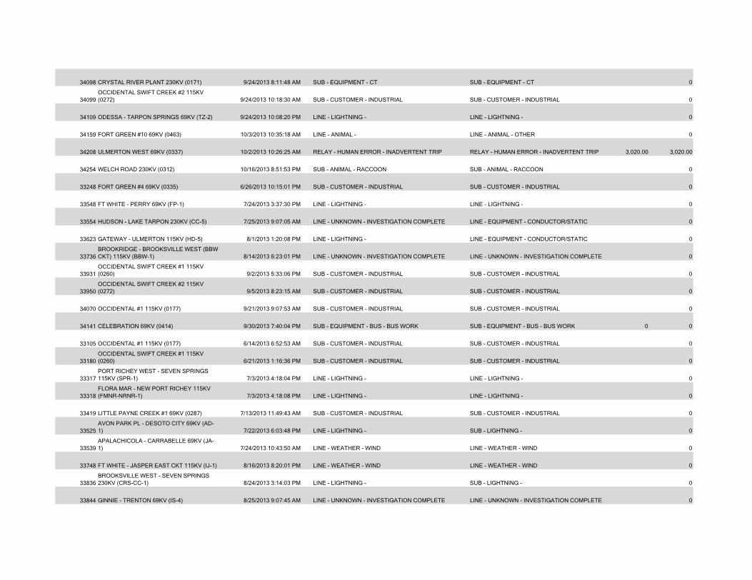
34098 CRYSTAL RIVER PLANT 230KV (0171) 9/24/2013 8:11:48 AM SUB - EQUIPMENT - CT SUB - EQUIPMENT - CT 0
34099OCCIDENTAL SWIFT CREEK #2 115KV (0272) 9/24/2013 10:18:30 AM SUB - CUSTOMER - INDUSTRIAL SUB - CUSTOMER - INDUSTRIAL 0
34109 ODESSA - TARPON SPRINGS 69KV (TZ-2) 9/24/2013 10:08:20 PM LINE - LIGHTNING - LINE - LIGHTNING - 0
34159 FORT GREEN #10 69KV (0463) 10/3/2013 10:35:18 AM LINE - ANIMAL - LINE - ANIMAL - OTHER 0
34208 ULMERTON WEST 69KV (0337) 10/2/2013 10:26:25 AM RELAY - HUMAN ERROR - INADVERTENT TRIP RELAY - HUMAN ERROR - INADVERTENT TRIP 3,020.00 3,020.00
34254 WELCH ROAD 230KV (0312) 10/16/2013 8:51:53 PM SUB - ANIMAL - RACCOON SUB - ANIMAL - RACCOON 0
33248 FORT GREEN #4 69KV (0335) 6/26/2013 10:15:01 PM SUB - CUSTOMER - INDUSTRIAL SUB - CUSTOMER - INDUSTRIAL 0
33548 FT WHITE - PERRY 69KV (FP-1) 7/24/2013 3:37:30 PM LINE - LIGHTNING - LINE - LIGHTNING - 0
33554 HUDSON - LAKE TARPON 230KV (CC-5) 7/25/2013 9:07:05 AM LINE - UNKNOWN - INVESTIGATION COMPLETE LINE - EQUIPMENT - CONDUCTOR/STATIC 0
33623 GATEWAY - ULMERTON 115KV (HD-5) 8/1/2013 1:20:08 PM LINE - LIGHTNING - LINE - EQUIPMENT - CONDUCTOR/STATIC 0
33736BROOKRIDGE - BROOKSVILLE WEST (BBW CKT) 115KV (BBW-1) 8/14/2013 6:23:01 PM LINE - UNKNOWN - INVESTIGATION COMPLETE LINE - UNKNOWN - INVESTIGATION COMPLETE 0
33931OCCIDENTAL SWIFT CREEK #1 115KV (0260) 9/2/2013 5:33:06 PM SUB - CUSTOMER - INDUSTRIAL SUB - CUSTOMER - INDUSTRIAL 0
33950OCCIDENTAL SWIFT CREEK #2 115KV (0272) 9/5/2013 8:23:15 AM SUB - CUSTOMER - INDUSTRIAL SUB - CUSTOMER - INDUSTRIAL 0
34070 OCCIDENTAL #1 115KV (0177) 9/21/2013 9:07:53 AM SUB - CUSTOMER - INDUSTRIAL SUB - CUSTOMER - INDUSTRIAL 0
34141 CELEBRATION 69KV (0414) 9/30/2013 7:40:04 PM SUB - EQUIPMENT - BUS - BUS WORK SUB - EQUIPMENT - BUS - BUS WORK 0 0
33105 OCCIDENTAL #1 115KV (0177) 6/14/2013 6:52:53 AM SUB - CUSTOMER - INDUSTRIAL SUB - CUSTOMER - INDUSTRIAL 0
33180OCCIDENTAL SWIFT CREEK #1 115KV (0260) 6/21/2013 1:16:36 PM SUB - CUSTOMER - INDUSTRIAL SUB - CUSTOMER - INDUSTRIAL 0
33317PORT RICHEY WEST - SEVEN SPRINGS 115KV (SPR-1) 7/3/2013 4:18:04 PM LINE - LIGHTNING - LINE - LIGHTNING - 0
33318FLORA MAR - NEW PORT RICHEY 115KV (FMNR-NRNR-1) 7/3/2013 4:18:08 PM LINE - LIGHTNING - LINE - LIGHTNING - 0
33419 LITTLE PAYNE CREEK #1 69KV (0287) 7/13/2013 11:49:43 AM SUB - CUSTOMER - INDUSTRIAL SUB - CUSTOMER - INDUSTRIAL 0
33525AVON PARK PL - DESOTO CITY 69KV (AD-1) 7/22/2013 6:03:48 PM LINE - LIGHTNING - SUB - LIGHTNING - 0
33539APALACHICOLA - CARRABELLE 69KV (JA-1) 7/24/2013 10:43:50 AM LINE - WEATHER - WIND LINE - WEATHER - WIND 0
33748 FT WHITE - JASPER EAST CKT 115KV (IJ-1) 8/16/2013 8:20:01 PM LINE - WEATHER - WIND LINE - WEATHER - WIND 0
33836BROOKSVILLE WEST - SEVEN SPRINGS 230KV (CRS-CC-1) 8/24/2013 3:14:03 PM LINE - LIGHTNING - SUB - LIGHTNING - 0
33844 GINNIE - TRENTON 69KV (IS-4) 8/25/2013 9:07:45 AM LINE - UNKNOWN - INVESTIGATION COMPLETE LINE - UNKNOWN - INVESTIGATION COMPLETE 0
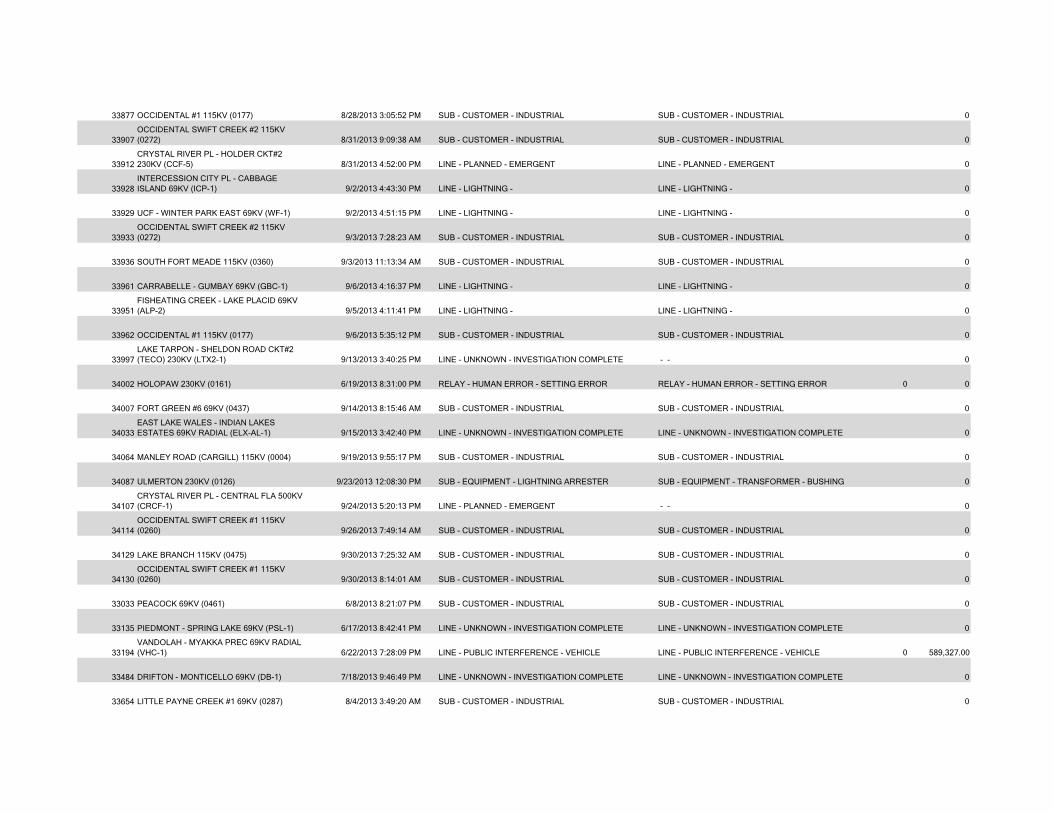
33877 OCCIDENTAL #1 115KV (0177) 8/28/2013 3:05:52 PM SUB - CUSTOMER - INDUSTRIAL SUB - CUSTOMER - INDUSTRIAL 0
33907OCCIDENTAL SWIFT CREEK #2 115KV (0272) 8/31/2013 9:09:38 AM SUB - CUSTOMER - INDUSTRIAL SUB - CUSTOMER - INDUSTRIAL 0
33912CRYSTAL RIVER PL - HOLDER CKT#2 230KV (CCF-5) 8/31/2013 4:52:00 PM LINE - PLANNED - EMERGENT LINE - PLANNED - EMERGENT 0
33928INTERCESSION CITY PL - CABBAGE ISLAND 69KV (ICP-1) 9/2/2013 4:43:30 PM LINE - LIGHTNING - LINE - LIGHTNING - 0
33929 UCF - WINTER PARK EAST 69KV (WF-1) 9/2/2013 4:51:15 PM LINE - LIGHTNING - LINE - LIGHTNING - 0
33933OCCIDENTAL SWIFT CREEK #2 115KV (0272) 9/3/2013 7:28:23 AM SUB - CUSTOMER - INDUSTRIAL SUB - CUSTOMER - INDUSTRIAL 0
33936 SOUTH FORT MEADE 115KV (0360) 9/3/2013 11:13:34 AM SUB - CUSTOMER - INDUSTRIAL SUB - CUSTOMER - INDUSTRIAL 0
33961 CARRABELLE - GUMBAY 69KV (GBC-1) 9/6/2013 4:16:37 PM LINE - LIGHTNING - LINE - LIGHTNING - 0
33951FISHEATING CREEK - LAKE PLACID 69KV (ALP-2) 9/5/2013 4:11:41 PM LINE - LIGHTNING - LINE - LIGHTNING - 0
33962 OCCIDENTAL #1 115KV (0177) 9/6/2013 5:35:12 PM SUB - CUSTOMER - INDUSTRIAL SUB - CUSTOMER - INDUSTRIAL 0
33997LAKE TARPON - SHELDON ROAD CKT#2 (TECO) 230KV (LTX2-1) 9/13/2013 3:40:25 PM LINE - UNKNOWN - INVESTIGATION COMPLETE - - 0
34002 HOLOPAW 230KV (0161) 6/19/2013 8:31:00 PM RELAY - HUMAN ERROR - SETTING ERROR RELAY - HUMAN ERROR - SETTING ERROR 0 0
34007 FORT GREEN #6 69KV (0437) 9/14/2013 8:15:46 AM SUB - CUSTOMER - INDUSTRIAL SUB - CUSTOMER - INDUSTRIAL 0
34033EAST LAKE WALES - INDIAN LAKES ESTATES 69KV RADIAL (ELX-AL-1) 9/15/2013 3:42:40 PM LINE - UNKNOWN - INVESTIGATION COMPLETE LINE - UNKNOWN - INVESTIGATION COMPLETE 0
34064 MANLEY ROAD (CARGILL) 115KV (0004) 9/19/2013 9:55:17 PM SUB - CUSTOMER - INDUSTRIAL SUB - CUSTOMER - INDUSTRIAL 0
34087 ULMERTON 230KV (0126) 9/23/2013 12:08:30 PM SUB - EQUIPMENT - LIGHTNING ARRESTER SUB - EQUIPMENT - TRANSFORMER - BUSHING 0
34107CRYSTAL RIVER PL - CENTRAL FLA 500KV (CRCF-1) 9/24/2013 5:20:13 PM LINE - PLANNED - EMERGENT - - 0
34114OCCIDENTAL SWIFT CREEK #1 115KV (0260) 9/26/2013 7:49:14 AM SUB - CUSTOMER - INDUSTRIAL SUB - CUSTOMER - INDUSTRIAL 0
34129 LAKE BRANCH 115KV (0475) 9/30/2013 7:25:32 AM SUB - CUSTOMER - INDUSTRIAL SUB - CUSTOMER - INDUSTRIAL 0
34130OCCIDENTAL SWIFT CREEK #1 115KV (0260) 9/30/2013 8:14:01 AM SUB - CUSTOMER - INDUSTRIAL SUB - CUSTOMER - INDUSTRIAL 0
33033 PEACOCK 69KV (0461) 6/8/2013 8:21:07 PM SUB - CUSTOMER - INDUSTRIAL SUB - CUSTOMER - INDUSTRIAL 0
33135 PIEDMONT - SPRING LAKE 69KV (PSL-1) 6/17/2013 8:42:41 PM LINE - UNKNOWN - INVESTIGATION COMPLETE LINE - UNKNOWN - INVESTIGATION COMPLETE 0
33194VANDOLAH - MYAKKA PREC 69KV RADIAL (VHC-1) 6/22/2013 7:28:09 PM LINE - PUBLIC INTERFERENCE - VEHICLE LINE - PUBLIC INTERFERENCE - VEHICLE 0 589,327.00
33484 DRIFTON - MONTICELLO 69KV (DB-1) 7/18/2013 9:46:49 PM LINE - UNKNOWN - INVESTIGATION COMPLETE LINE - UNKNOWN - INVESTIGATION COMPLETE 0
33654 LITTLE PAYNE CREEK #1 69KV (0287) 8/4/2013 3:49:20 AM SUB - CUSTOMER - INDUSTRIAL SUB - CUSTOMER - INDUSTRIAL 0
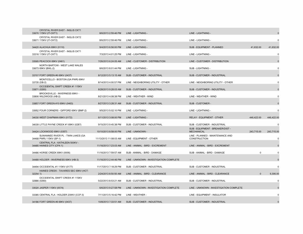
33670CRYSTAL RIVER EAST - INGLIS CKT1 115KV (IT-CKT1) 8/6/2013 2:59:46 PM LINE - LIGHTNING - LINE - LIGHTNING - 0
33671CRYSTAL RIVER EAST - INGLIS CKT2 115KV (IT-CKT2) 8/6/2013 2:59:46 PM LINE - LIGHTNING - LINE - LIGHTNING - 0
34420 ALACHUA 69KV (0110) 9/4/2013 6:56:00 PM LINE - LIGHTNING - SUB - EQUIPMENT - PLANNED 41,632.00 41,632.00
33316CRYSTAL RIVER EAST - INGLIS CKT1 115KV (IT-CKT1) 7/3/2013 4:01:25 PM LINE - LIGHTNING - LINE - LIGHTNING - 0
33565 PEACOCK 69KV (0461) 7/26/2013 6:24:05 AM LINE - CUSTOMER - DISTRIBUTION LINE - CUSTOMER - DISTRIBUTION 0
33673NORTH BARTOW - WEST LAKE WALES 69KV (BWL-2) 8/6/2013 8:01:44 PM LINE - LIGHTNING - SUB - LIGHTNING - 0
33707 FORT GREEN #6 69KV (0437) 8/12/2013 5:13:15 AM SUB - CUSTOMER - INDUSTRIAL SUB - CUSTOMER - INDUSTRIAL 0
33735MONTICELLO - BOSTON (GA PWR) 69KV (DB-2) 8/14/2013 4:00:57 PM LINE - NEIGHBORING UTILITY - OTHER LINE - NEIGHBORING UTILITY - OTHER 0
33871OCCIDENTAL SWIFT CREEK #1 115KV (0260) 8/28/2013 9:28:03 AM SUB - CUSTOMER - INDUSTRIAL SUB - CUSTOMER - INDUSTRIAL 0
33806BROOKSVILLE - INVERNESS 69KV - WILDWOOD (HB-2) 8/21/2013 4:08:38 PM LINE - WEATHER - WIND LINE - WEATHER - WIND 0
33857 FORT GREEN #10 69KV (0463) 8/27/2013 3:28:31 AM SUB - CUSTOMER - INDUSTRIAL SUB - CUSTOMER - 0
33952 FOUR CORNERS - GIFFORD 69KV (BMF-2) 9/5/2013 5:02:10 PM LINE - LIGHTNING - LINE - LIGHTNING - 0
34030 WEST CHAPMAN 69KV (0172) 6/11/2013 3:08:00 PM LINE - LIGHTNING - RELAY - EQUIPMENT - OTHER 446,422.00 446,422.00
34039 LITTLE PAYNE CREEK #1 69KV (0287) 9/15/2013 9:45:38 PM SUB - CUSTOMER - INDUSTRIAL SUB - CUSTOMER - INDUSTRIAL 0
34424 LOCKWOOD 69KV (0357) 10/10/2013 8:58:00 PM LINE - UNKNOWN - SUB - EQUIPMENT - BREAKER/DIST - MECHANICAL 243,715.00 243,715.00
34468SUWANNEE RIVER PL - TWIN LAKES (GA PWR) 115KV (SP-1) 11/13/2013 11:08:03 AM LINE - EQUIPMENT - OTHER
LINE - PLANNED - MAINTENANCE AND CONSTRUCTION 0
34485CENTRAL FLA - KATHLEEN 500KV - HAINES CITY (CFK-1) 11/16/2013 7:23:03 AM LINE - ANIMAL - BIRD - EXCREMENT LINE - ANIMAL - BIRD - EXCREMENT 0
34486 HORSE CREEK 69KV (0006) 11/16/2013 7:59:57 AM SUB - ANIMAL - BIRD - DAMAGE SUB - ANIMAL - BIRD - DAMAGE 0 0
34489 HOLDER - INVERNESS 69KV (HB-3) 11/16/2013 2:44:46 PM LINE - UNKNOWN - INVESTIGATION COMPLETE - - 0
34494 OCCIDENTAL #1 115KV (0177) 11/17/2013 7:18:29 PM SUB - CUSTOMER - INDUSTRIAL SUB - CUSTOMER - INDUSTRIAL 0
32254HAINES CREEK - TAVARES SEC 69KV (HCT-1) 2/24/2013 8:50:50 AM LINE - ANIMAL - BIRD - CLEARANCE LINE - ANIMAL - BIRD - CLEARANCE 0 9,306.00
32886OCCIDENTAL SWIFT CREEK #1 115KV (0260) 5/22/2013 8:53:21 AM SUB - CUSTOMER - INDUSTRIAL SUB - CUSTOMER - INDUSTRIAL 0
33020 JASPER 115KV (0074) 6/6/2013 9:27:58 PM LINE - UNKNOWN - INVESTIGATION COMPLETE LINE - UNKNOWN - INVESTIGATION COMPLETE 0
33385 CENTRAL FLA - HOLDER 230KV (CCF-3) 7/11/2013 5:16:42 PM LINE - WEATHER - LINE - EQUIPMENT - INSULATOR 0
34186 FORT GREEN #6 69KV (0437) 10/8/2013 7:33:51 AM SUB - CUSTOMER - INDUSTRIAL SUB - CUSTOMER - INDUSTRIAL 0
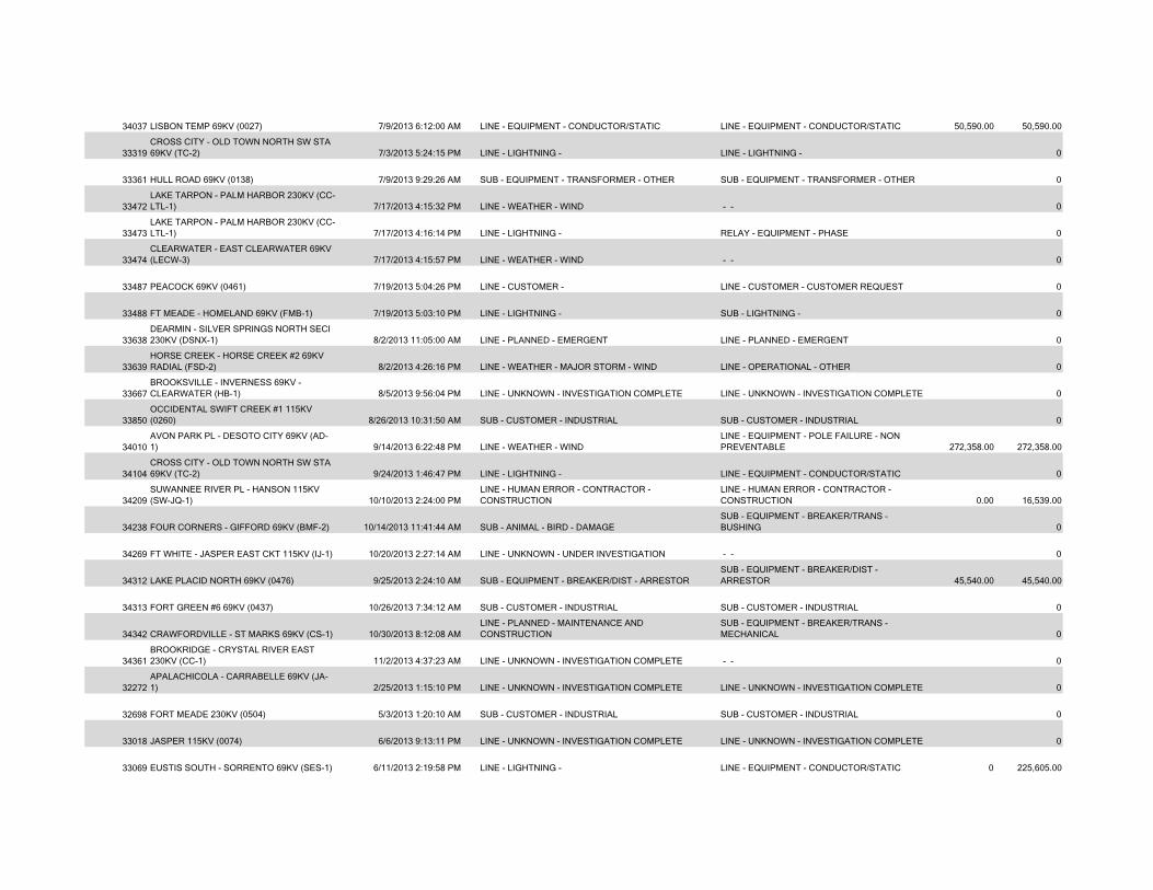
34037 LISBON TEMP 69KV (0027) 7/9/2013 6:12:00 AM LINE - EQUIPMENT - CONDUCTOR/STATIC LINE - EQUIPMENT - CONDUCTOR/STATIC 50,590.00 50,590.00
33319CROSS CITY - OLD TOWN NORTH SW STA 69KV (TC-2) 7/3/2013 5:24:15 PM LINE - LIGHTNING - LINE - LIGHTNING - 0
33361 HULL ROAD 69KV (0138) 7/9/2013 9:29:26 AM SUB - EQUIPMENT - TRANSFORMER - OTHER SUB - EQUIPMENT - TRANSFORMER - OTHER 0
33472LAKE TARPON - PALM HARBOR 230KV (CC-LTL-1) 7/17/2013 4:15:32 PM LINE - WEATHER - WIND - - 0
33473LAKE TARPON - PALM HARBOR 230KV (CC-LTL-1) 7/17/2013 4:16:14 PM LINE - LIGHTNING - RELAY - EQUIPMENT - PHASE 0
33474CLEARWATER - EAST CLEARWATER 69KV (LECW-3) 7/17/2013 4:15:57 PM LINE - WEATHER - WIND - - 0
33487 PEACOCK 69KV (0461) 7/19/2013 5:04:26 PM LINE - CUSTOMER - LINE - CUSTOMER - CUSTOMER REQUEST 0
33488 FT MEADE - HOMELAND 69KV (FMB-1) 7/19/2013 5:03:10 PM LINE - LIGHTNING - SUB - LIGHTNING - 0
33638DEARMIN - SILVER SPRINGS NORTH SECI 230KV (DSNX-1) 8/2/2013 11:05:00 AM LINE - PLANNED - EMERGENT LINE - PLANNED - EMERGENT 0
33639HORSE CREEK - HORSE CREEK #2 69KV RADIAL (FSD-2) 8/2/2013 4:26:16 PM LINE - WEATHER - MAJOR STORM - WIND LINE - OPERATIONAL - OTHER 0
33667BROOKSVILLE - INVERNESS 69KV - CLEARWATER (HB-1) 8/5/2013 9:56:04 PM LINE - UNKNOWN - INVESTIGATION COMPLETE LINE - UNKNOWN - INVESTIGATION COMPLETE 0
33850OCCIDENTAL SWIFT CREEK #1 115KV (0260) 8/26/2013 10:31:50 AM SUB - CUSTOMER - INDUSTRIAL SUB - CUSTOMER - INDUSTRIAL 0
34010AVON PARK PL - DESOTO CITY 69KV (AD-1) 9/14/2013 6:22:48 PM LINE - WEATHER - WIND
LINE - EQUIPMENT - POLE FAILURE - NON PREVENTABLE 272,358.00 272,358.00
34104CROSS CITY - OLD TOWN NORTH SW STA 69KV (TC-2) 9/24/2013 1:46:47 PM LINE - LIGHTNING - LINE - EQUIPMENT - CONDUCTOR/STATIC 0
34209SUWANNEE RIVER PL - HANSON 115KV (SW-JQ-1) 10/10/2013 2:24:00 PM
LINE - HUMAN ERROR - CONTRACTOR - CONSTRUCTION
LINE - HUMAN ERROR - CONTRACTOR - CONSTRUCTION 0.00 16,539.00
34238 FOUR CORNERS - GIFFORD 69KV (BMF-2) 10/14/2013 11:41:44 AM SUB - ANIMAL - BIRD - DAMAGESUB - EQUIPMENT - BREAKER/TRANS - BUSHING 0
34269 FT WHITE - JASPER EAST CKT 115KV (IJ-1) 10/20/2013 2:27:14 AM LINE - UNKNOWN - UNDER INVESTIGATION - - 0
34312 LAKE PLACID NORTH 69KV (0476) 9/25/2013 2:24:10 AM SUB - EQUIPMENT - BREAKER/DIST - ARRESTORSUB - EQUIPMENT - BREAKER/DIST - ARRESTOR 45,540.00 45,540.00
34313 FORT GREEN #6 69KV (0437) 10/26/2013 7:34:12 AM SUB - CUSTOMER - INDUSTRIAL SUB - CUSTOMER - INDUSTRIAL 0
34342 CRAWFORDVILLE - ST MARKS 69KV (CS-1) 10/30/2013 8:12:08 AMLINE - PLANNED - MAINTENANCE AND CONSTRUCTION
SUB - EQUIPMENT - BREAKER/TRANS - MECHANICAL 0
34361BROOKRIDGE - CRYSTAL RIVER EAST 230KV (CC-1) 11/2/2013 4:37:23 AM LINE - UNKNOWN - INVESTIGATION COMPLETE - - 0
32272APALACHICOLA - CARRABELLE 69KV (JA-1) 2/25/2013 1:15:10 PM LINE - UNKNOWN - INVESTIGATION COMPLETE LINE - UNKNOWN - INVESTIGATION COMPLETE 0
32698 FORT MEADE 230KV (0504) 5/3/2013 1:20:10 AM SUB - CUSTOMER - INDUSTRIAL SUB - CUSTOMER - INDUSTRIAL 0
33018 JASPER 115KV (0074) 6/6/2013 9:13:11 PM LINE - UNKNOWN - INVESTIGATION COMPLETE LINE - UNKNOWN - INVESTIGATION COMPLETE 0
33069 EUSTIS SOUTH - SORRENTO 69KV (SES-1) 6/11/2013 2:19:58 PM LINE - LIGHTNING - LINE - EQUIPMENT - CONDUCTOR/STATIC 0 225,605.00
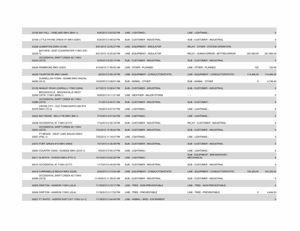
33159 BAY HILL - VINELAND 69KV (BHV-1) 6/20/2013 3:53:52 PM LINE - LIGHTNING - LINE - LIGHTNING - 0
33160 LITTLE PAYNE CREEK #1 69KV (0287) 6/20/2013 3:56:52 PM SUB - CUSTOMER - INDUSTRIAL SUB - CUSTOMER - INDUSTRIAL 0
33228 ULMERTON 230KV (0126) 6/21/2013 12:05:27 PM LINE - EQUIPMENT - INSULATOR RELAY - OTHER - SYSTEM OPERATION 0
33229BAYVIEW - EAST CLEARWATER 115KV (HD-1) 6/21/2013 12:05:26 PM LINE - EQUIPMENT - INSULATOR RELAY - HUMAN ERROR - SETTING ERROR 291,483.00 291,483.00
33233OCCIDENTAL SWIFT CREEK #2 115KV (0272) 6/25/2013 8:25:13 PM SUB - CUSTOMER - INDUSTRIAL SUB - CUSTOMER - INDUSTRIAL 0
34026 PEMBROKE 69KV (0327) 4/14/2013 11:59:00 AM LINE - OTHER - PLANNED LINE - OTHER - PLANNED 120 120.00
34028 TAUNTON RD 69KV (0449) 8/5/2013 5:58:18 PM LINE - EQUIPMENT - CONDUCTOR/STATIC LINE - EQUIPMENT - CONDUCTOR/STATIC 114,466.00 114,466.00
34292DUNNELLON TOWN - ADAMS 69KV RADIAL (IO-2) 10/23/2013 3:08:57 AM SUB - ANIMAL - OTHER SUB - ANIMAL - OTHER 0 4,746.40
33136 MANLEY ROAD (CARGILL) 115KV (0004) 6/17/2013 10:56:41 PM SUB - CUSTOMER - INDUSTRIAL SUB - CUSTOMER - INDUSTRIAL 0
33269BROOKSVILLE - BROOKSVILLE WEST CKT#1 115KV (BWB-1) 6/29/2013 9:11:31 AM LINE - WEATHER - MAJOR STORM - - 0
33285OCCIDENTAL SWIFT CREEK #2 115KV (0272) 7/1/2013 6:40:27 AM SUB - CUSTOMER - INDUSTRIAL SUB - CUSTOMER - 0
33370CROSS CITY - OLD TOWN NORTH SW STA 69KV (TC-2) 7/9/2013 5:07:07 PM LINE - LIGHTNING - LINE - LIGHTNING - 0
33422 BAY RIDGE - KELLY PK 69KV (BK-1) 7/13/2013 4:01:54 PM LINE - LIGHTNING - LINE - LIGHTNING - 0
33438 OCCIDENTAL #1 115KV (0177) 7/15/2013 2:55:18 PM SUB - CUSTOMER - INDUSTRIAL RELAY - CUSTOMER - INDUSTRIAL 0
33533OCCIDENTAL SWIFT CREEK #2 115KV (0272) 7/23/2013 10:38:44 PM SUB - CUSTOMER - INDUSTRIAL SUB - CUSTOMER - INDUSTRIAL 0
33557FT MEADE - WEST LAKE WALES 230KV (FWL-1) 7/25/2013 11:16:07 PM LINE - LIGHTNING - LINE - LIGHTNING - 0
33573 FORT GREEN #10 69KV (0463) 7/27/2013 4:35:09 PM SUB - CUSTOMER - INDUSTRIAL SUB - CUSTOMER - INDUSTRIAL 0
33953 COUNTRY OAKS - DUNDEE 69KV (DCO-1) 9/5/2013 5:50:37 PM LINE - LIGHTNING - LINE - LIGHTNING - 0
34211 ALAFAYA - OVIEDO 69KV (FTO-1) 10/10/2013 9:02:25 PM LINE - LIGHTNING - SUB - EQUIPMENT - BREAKER/DIST - MECHANICAL 0
34410 OCCIDENTAL #1 115KV (0177) 11/7/2013 4:34:59 PM SUB - CUSTOMER - INDUSTRIAL SUB - CUSTOMER - INDUSTRIAL 0
34419 CARRABELLE BEACH 69KV (0226) 3/24/2013 3:13:00 AM LINE - EQUIPMENT - CONDUCTOR/STATIC LINE - EQUIPMENT - CONDUCTOR/STATIC 100,320.00 100,320.00
34499OCCIDENTAL SWIFT CREEK #2 115KV (0272) 11/18/2013 11:28:42 AM SUB - CUSTOMER - INDUSTRIAL SUB - CUSTOMER - INDUSTRIAL 0
34505 DRIFTON - HANSON 115KV (JQ-4) 11/18/2013 3:16:17 PM LINE - TREE - NON-PREVENTABLE LINE - TREE - NON-PREVENTABLE 0
34506 DRIFTON - HANSON 115KV (JQ-4) 11/18/2013 3:17:52 PM LINE - TREE - PREVENTABLE LINE - TREE - PREVENTABLE 0 4,464.00
34507 FT WHITE - JASPER EAST CKT 115KV (IJ-1) 11/18/2013 3:44:49 PM LINE - ANIMAL - BIRD - EXCREMENT - - 0
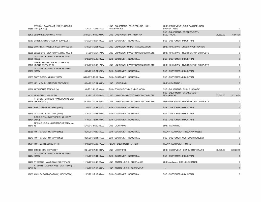
34555AVALON - CAMP LAKE 230KV - HAINES CITY (CFW-2) 11/26/2013 7:56:11 AM
LINE - EQUIPMENT - POLE FAILURE - NON PREVENTABLE
LINE - EQUIPMENT - POLE FAILURE - NON PREVENTABLE 0
32470 LEISURE LAKES 69KV (0355) 2/19/2013 11:00:08 PM LINE - CUSTOMER - DISTRIBUTIONSUB - EQUIPMENT - BREAKER/DIST - ELECTRICAL 76,563.00 76,563.00
32763 LITTLE PAYNE CREEK #1 69KV (0287) 5/12/2013 5:57:39 AM SUB - CUSTOMER - INDUSTRIAL SUB - CUSTOMER - INDUSTRIAL 0
32822 UMATILLA - PAISELY (SEC) 69KV (ED-3) 5/19/2013 3:51:05 AM LINE - UNKNOWN - UNDER INVESTIGATION LINE - UNKNOWN - UNDER INVESTIGATION 0
32998 LEESBURG - OKAHUMPKA 69KV (CLL-2) 6/4/2013 7:57:47 PM LINE - UNKNOWN - INVESTIGATION COMPLETE LINE - UNKNOWN - INVESTIGATION COMPLETE 0
33075OCCIDENTAL SWIFT CREEK #1 115KV (0260) 6/12/2013 7:22:42 AM SUB - CUSTOMER - INDUSTRIAL SUB - CUSTOMER - INDUSTRIAL 0
33143INTERCESSION CITY PL - CABBAGE ISLAND 69KV (ICP-1) 6/18/2013 8:48:17 PM LINE - UNKNOWN - INVESTIGATION COMPLETE LINE - UNKNOWN - INVESTIGATION COMPLETE 0
33230OCCIDENTAL SWIFT CREEK #1 115KV (0260) 6/25/2013 5:21:02 PM SUB - CUSTOMER - INDUSTRIAL SUB - CUSTOMER - INDUSTRIAL 0
33235 FORT GREEN #4 69KV (0335) 6/26/2013 10:17:29 AM SUB - CUSTOMER - INDUSTRIAL SUB - CUSTOMER - INDUSTRIAL 0
33835 KELLY PARK - MT DORA 69KV (EP-5) 8/24/2013 3:04:34 PM LINE - LIGHTNING - LINE - LIGHTNING - 0
33968 ALTAMONTE 230KV (0136) 9/8/2013 11:18:30 AM SUB - EQUIPMENT - BUS - BUS WORK SUB - EQUIPMENT - BUS - BUS WORK 0
34015 KENNETH 115KV (0174) 5/1/2013 7:13:48 AM LINE - UNKNOWN - INVESTIGATION COMPLETESUB - EQUIPMENT - BREAKER/DIST - MECHANICAL 57,316.00 57,316.00
33148FT GREEN SPRINGS - VANDOLAH #2 CKT 69KV (VFGS-1) 6/19/2013 3:07:32 PM LINE - UNKNOWN - INVESTIGATION COMPLETE LINE - UNKNOWN - INVESTIGATION COMPLETE 0
33362 FORT GREEN #10 69KV (0463) 7/9/2013 9:51:31 AM SUB - CUSTOMER - INDUSTRIAL SUB - CUSTOMER - INDUSTRIAL 0
33449 OCCIDENTAL #1 115KV (0177) 7/16/2013 1:34:56 PM SUB - CUSTOMER - INDUSTRIAL SUB - CUSTOMER - INDUSTRIAL 0
33494OCCIDENTAL SWIFT CREEK #2 115KV (0272) 7/19/2013 8:34:54 PM SUB - CUSTOMER - INDUSTRIAL SUB - CUSTOMER - INDUSTRIAL 0
33540APALACHICOLA - CARRABELLE 69KV (JA-1) 7/24/2013 11:09:36 AM LINE - LIGHTNING - LINE - LIGHTNING - 0
33769 FORT GREEN #10 69KV (0463) 8/20/2013 4:29:55 AM SUB - CUSTOMER - INDUSTRIAL RELAY - EQUIPMENT - RELAY PROBLEM 0
33843 FORT GREEN #11 69KV (0472) 8/25/2013 8:01:41 AM SUB - CUSTOMER - INDUSTRIAL SUB - CUSTOMER - CUSTOMER REQUEST 0
34264 FORT WHITE 230KV (0111) 10/18/2013 7:03:47 AM RELAY - EQUIPMENT - OTHER RELAY - EQUIPMENT - OTHER 0
34426 CROSS CITY 69KV (0081) 9/24/2013 1:46:00 PM LINE - LIGHTNING - LINE - EQUIPMENT - CONDUCTOR/STATIC 33,728.00 33,728.00
34464OCCIDENTAL SWIFT CREEK #1 115KV (0260) 11/13/2013 1:44:19 AM SUB - CUSTOMER - INDUSTRIAL SUB - CUSTOMER - INDUSTRIAL 0
34496 FT MEADE - VANDOLAH 230KV (FV-1) 11/18/2013 4:46:22 AM LINE - ANIMAL - BIRD - CLEARANCE LINE - ANIMAL - BIRD - CLEARANCE 0
34510FT WHITE - JASPER WEST CKT 115KV (IJ-2) 11/18/2013 5:18:03 PM LINE - ANIMAL - BIRD - EXCREMENT - - 0
32137 MANLEY ROAD (CARGILL) 115KV (0004) 1/27/2013 7:12:35 AM SUB - CUSTOMER - INDUSTRIAL SUB - CUSTOMER - INDUSTRIAL 0
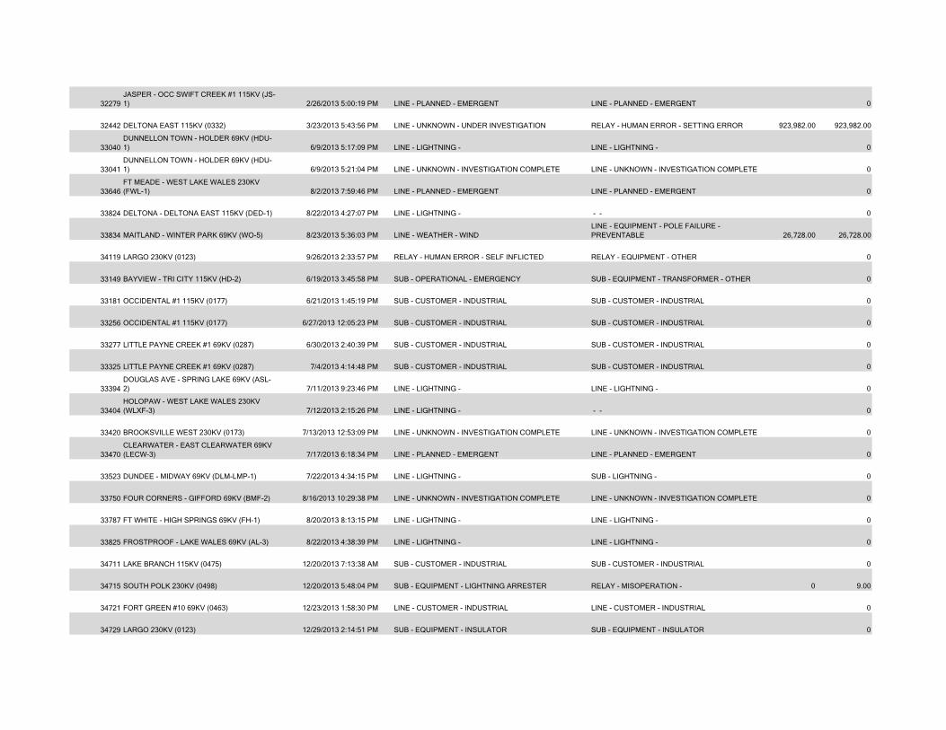
32279JASPER - OCC SWIFT CREEK #1 115KV (JS-1) 2/26/2013 5:00:19 PM LINE - PLANNED - EMERGENT LINE - PLANNED - EMERGENT 0
32442 DELTONA EAST 115KV (0332) 3/23/2013 5:43:56 PM LINE - UNKNOWN - UNDER INVESTIGATION RELAY - HUMAN ERROR - SETTING ERROR 923,982.00 923,982.00
33040DUNNELLON TOWN - HOLDER 69KV (HDU-1) 6/9/2013 5:17:09 PM LINE - LIGHTNING - LINE - LIGHTNING - 0
33041DUNNELLON TOWN - HOLDER 69KV (HDU-1) 6/9/2013 5:21:04 PM LINE - UNKNOWN - INVESTIGATION COMPLETE LINE - UNKNOWN - INVESTIGATION COMPLETE 0
33646FT MEADE - WEST LAKE WALES 230KV (FWL-1) 8/2/2013 7:59:46 PM LINE - PLANNED - EMERGENT LINE - PLANNED - EMERGENT 0
33824 DELTONA - DELTONA EAST 115KV (DED-1) 8/22/2013 4:27:07 PM LINE - LIGHTNING - - - 0
33834 MAITLAND - WINTER PARK 69KV (WO-5) 8/23/2013 5:36:03 PM LINE - WEATHER - WINDLINE - EQUIPMENT - POLE FAILURE - PREVENTABLE 26,728.00 26,728.00
34119 LARGO 230KV (0123) 9/26/2013 2:33:57 PM RELAY - HUMAN ERROR - SELF INFLICTED RELAY - EQUIPMENT - OTHER 0
33149 BAYVIEW - TRI CITY 115KV (HD-2) 6/19/2013 3:45:58 PM SUB - OPERATIONAL - EMERGENCY SUB - EQUIPMENT - TRANSFORMER - OTHER 0
33181 OCCIDENTAL #1 115KV (0177) 6/21/2013 1:45:19 PM SUB - CUSTOMER - INDUSTRIAL SUB - CUSTOMER - INDUSTRIAL 0
33256 OCCIDENTAL #1 115KV (0177) 6/27/2013 12:05:23 PM SUB - CUSTOMER - INDUSTRIAL SUB - CUSTOMER - INDUSTRIAL 0
33277 LITTLE PAYNE CREEK #1 69KV (0287) 6/30/2013 2:40:39 PM SUB - CUSTOMER - INDUSTRIAL SUB - CUSTOMER - INDUSTRIAL 0
33325 LITTLE PAYNE CREEK #1 69KV (0287) 7/4/2013 4:14:48 PM SUB - CUSTOMER - INDUSTRIAL SUB - CUSTOMER - INDUSTRIAL 0
33394DOUGLAS AVE - SPRING LAKE 69KV (ASL-2) 7/11/2013 9:23:46 PM LINE - LIGHTNING - LINE - LIGHTNING - 0
33404HOLOPAW - WEST LAKE WALES 230KV (WLXF-3) 7/12/2013 2:15:26 PM LINE - LIGHTNING - - - 0
33420 BROOKSVILLE WEST 230KV (0173) 7/13/2013 12:53:09 PM LINE - UNKNOWN - INVESTIGATION COMPLETE LINE - UNKNOWN - INVESTIGATION COMPLETE 0
33470CLEARWATER - EAST CLEARWATER 69KV (LECW-3) 7/17/2013 6:18:34 PM LINE - PLANNED - EMERGENT LINE - PLANNED - EMERGENT 0
33523 DUNDEE - MIDWAY 69KV (DLM-LMP-1) 7/22/2013 4:34:15 PM LINE - LIGHTNING - SUB - LIGHTNING - 0
33750 FOUR CORNERS - GIFFORD 69KV (BMF-2) 8/16/2013 10:29:38 PM LINE - UNKNOWN - INVESTIGATION COMPLETE LINE - UNKNOWN - INVESTIGATION COMPLETE 0
33787 FT WHITE - HIGH SPRINGS 69KV (FH-1) 8/20/2013 8:13:15 PM LINE - LIGHTNING - LINE - LIGHTNING - 0
33825 FROSTPROOF - LAKE WALES 69KV (AL-3) 8/22/2013 4:38:39 PM LINE - LIGHTNING - LINE - LIGHTNING - 0
34711 LAKE BRANCH 115KV (0475) 12/20/2013 7:13:38 AM SUB - CUSTOMER - INDUSTRIAL SUB - CUSTOMER - INDUSTRIAL 0
34715 SOUTH POLK 230KV (0498) 12/20/2013 5:48:04 PM SUB - EQUIPMENT - LIGHTNING ARRESTER RELAY - MISOPERATION - 0 9.00
34721 FORT GREEN #10 69KV (0463) 12/23/2013 1:58:30 PM LINE - CUSTOMER - INDUSTRIAL LINE - CUSTOMER - INDUSTRIAL 0
34729 LARGO 230KV (0123) 12/29/2013 2:14:51 PM SUB - EQUIPMENT - INSULATOR SUB - EQUIPMENT - INSULATOR 0
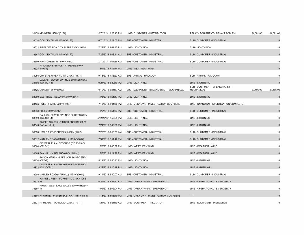
32174 KENNETH 115KV (0174) 1/27/2013 10:23:43 PM LINE - CUSTOMER - DISTRIBUTION RELAY - EQUIPMENT - RELAY PROBLEM 84,081.00 84,081.00
33024 OCCIDENTAL #1 115KV (0177) 6/7/2013 12:17:00 PM SUB - CUSTOMER - INDUSTRIAL SUB - CUSTOMER - INDUSTRIAL 0
33522 INTERCESSION CITY PLANT 230KV (0166) 7/22/2013 3:44:15 PM LINE - LIGHTNING - SUB - LIGHTNING - 0
33567 OCCIDENTAL #1 115KV (0177) 7/26/2013 8:03:11 AM SUB - CUSTOMER - INDUSTRIAL SUB - CUSTOMER - INDUSTRIAL 0
33609 FORT GREEN #11 69KV (0472) 7/31/2013 11:04:36 AM SUB - CUSTOMER - INDUSTRIAL SUB - CUSTOMER - INDUSTRIAL 0
33627FT GREEN SPRINGS - FT MEADE 69KV (FFG-1) 8/1/2013 7:15:44 PM LINE - WEATHER - WIND - - 0
34056 CRYSTAL RIVER PLANT 230KV (0171) 9/18/2013 1:13:23 AM SUB - ANIMAL - RACCOON SUB - ANIMAL - RACCOON 0
34108DALLAS - SILVER SPRINGS SHORES 69KV (DW-OCF-1) 9/24/2013 6:30:10 PM LINE - LIGHTNING - LINE - LIGHTNING - 0
34425 DUNEDIN 69KV (0059) 10/10/2013 2:24:37 AM SUB - EQUIPMENT - BREAKER/DIST - MECHANICALSUB - EQUIPMENT - BREAKER/DIST - MECHANICAL 27,405.00 27,405.00
33309 BAY RIDGE - KELLY PK 69KV (BK-1) 7/3/2013 1:54:17 PM LINE - LIGHTNING - LINE - LIGHTNING - 0
33436 ROSS PRAIRIE 230KV (0407) 7/15/2013 2:04:50 PM LINE - UNKNOWN - INVESTIGATION COMPLETE LINE - UNKNOWN - INVESTIGATION COMPLETE 0
33330 FOLEY 69KV (0247) 7/5/2013 1:51:07 PM SUB - CUSTOMER - INDUSTRIAL SUB - CUSTOMER - INDUSTRIAL 0
33399DALLAS - SILVER SPRINGS SHORES 69KV (DW-OCF-1) 7/12/2013 12:56:59 PM LINE - LIGHTNING - LINE - LIGHTNING - 0
33543TIMBER SW STA - TIMBER ENERGY 69KV RADIAL (JH-2) 7/24/2013 2:40:55 PM LINE - LIGHTNING - LINE - LIGHTNING - 0
33553 LITTLE PAYNE CREEK #1 69KV (0287) 7/25/2013 8:59:37 AM SUB - CUSTOMER - INDUSTRIAL SUB - CUSTOMER - INDUSTRIAL 0
33612 MANLEY ROAD (CARGILL) 115KV (0004) 7/31/2013 2:51:42 PM SUB - CUSTOMER - INDUSTRIAL SUB - CUSTOMER - INDUSTRIAL 0
33664CENTRAL FLA - LEESBURG (CFLE) 69KV (CFLE-1) 8/5/2013 8:05:32 PM LINE - WEATHER - WIND LINE - WEATHER - WIND 0
33665 BAY HILL - VINELAND 69KV (BHV-1) 8/5/2013 8:11:28 PM LINE - WEATHER - WIND LINE - WEATHER - WIND 0
33734BOGGY MARSH - LAKE LOUISA SEC 69KV (CEB-2) 8/14/2013 3:50:17 PM LINE - LIGHTNING - LINE - LIGHTNING - 0
33822CENTRAL FLA - ORANGE BLOSSOM 69KV (DLL-OCF-1) 8/22/2013 3:16:49 PM LINE - LIGHTNING - LINE - LIGHTNING - 0
33986 MANLEY ROAD (CARGILL) 115KV (0004) 9/11/2013 2:40:07 AM SUB - CUSTOMER - INDUSTRIAL SUB - CUSTOMER - INDUSTRIAL 0
34333HAINES CREEK - SORRENTO 230KV (CFS-2) 10/29/2013 8:54:52 AM LINE - OPERATIONAL - EMERGENCY LINE - OPERATIONAL - EMERGENCY 0
34397HINES - WEST LAKE WALES 230KV (HWLW-1) 11/6/2013 2:05:04 PM LINE - OPERATIONAL - EMERGENCY LINE - OPERATIONAL - EMERGENCY 0
34504 FT WHITE - JASPER EAST CKT 115KV (IJ-1) 11/18/2013 3:03:19 PM LINE - UNKNOWN - INVESTIGATION COMPLETE - - 0
34531 FT MEADE - VANDOLAH 230KV (FV-1) 11/21/2013 2:51:19 AM LINE - EQUIPMENT - INSULATOR LINE - EQUIPMENT - INSULATOR 0
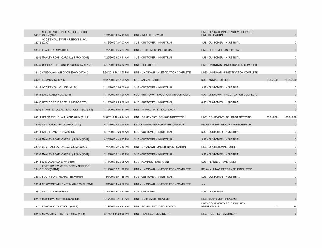
34570NORTHEAST - PINELLAS COUNTY RR 230KV (NX-1) 12/1/2013 6:35:15 AM LINE - WEATHER - WIND
LINE - OPERATIONAL - SYSTEM OPERATING LIMIT MITIGATION 0
32775OCCIDENTAL SWIFT CREEK #1 115KV (0260) 5/13/2013 7:07:07 AM SUB - CUSTOMER - INDUSTRIAL SUB - CUSTOMER - INDUSTRIAL 0
33300 PEACOCK 69KV (0461) 7/2/2013 3:45:23 PM LINE - CUSTOMER - INDUSTRIAL LINE - CUSTOMER - INDUSTRIAL 0
33555 MANLEY ROAD (CARGILL) 115KV (0004) 7/25/2013 9:26:11 AM SUB - CUSTOMER - INDUSTRIAL SUB - CUSTOMER - INDUSTRIAL 0
33767 ODESSA - TARPON SPRINGS 69KV (TZ-2) 8/19/2013 6:56:32 PM LINE - LIGHTNING - LINE - UNKNOWN - INVESTIGATION COMPLETE 0
34110 VANDOLAH - WHIDDON 230KV (VWX-1) 9/24/2013 10:14:50 PM LINE - UNKNOWN - INVESTIGATION COMPLETE LINE - UNKNOWN - INVESTIGATION COMPLETE 0
34295 ADAMS 69KV (0286) 10/23/2013 3:17:54 AM SUB - ANIMAL - OTHER SUB - ANIMAL - OTHER 29,553.00 29,553.00
34433 OCCIDENTAL #3 115KV (0188) 11/11/2013 2:05:00 AM SUB - CUSTOMER - INDUSTRIAL SUB - CUSTOMER - INDUSTRIAL 0
34434 LAKE WALES 69KV (0318) 11/11/2013 8:44:26 AM SUB - UNKNOWN - INVESTIGATION COMPLETE SUB - UNKNOWN - INVESTIGATION COMPLETE 0
34453 LITTLE PAYNE CREEK #1 69KV (0287) 11/12/2013 8:25:00 AM SUB - CUSTOMER - INDUSTRIAL SUB - CUSTOMER - INDUSTRIAL 0
34508 FT WHITE - JASPER EAST CKT 115KV (IJ-1) 11/18/2013 5:04:11 PM LINE - ANIMAL - BIRD - EXCREMENT - - 0
34624 LEESBURG - OKAHUMPKA 69KV (CLL-2) 12/8/2013 12:48:14 AM LINE - EQUIPMENT - CONDUCTOR/STATIC LINE - EQUIPMENT - CONDUCTOR/STATIC 65,697.00 65,697.00
33106 CENTRAL FLORIDA 500KV (0170) 6/14/2013 9:42:56 AM RELAY - HUMAN ERROR - WIRING ERROR RELAY - HUMAN ERROR - WIRING ERROR 0
33114 LAKE BRANCH 115KV (0475) 6/16/2013 7:28:35 AM SUB - CUSTOMER - INDUSTRIAL SUB - CUSTOMER - INDUSTRIAL 0
33162 MANLEY ROAD (CARGILL) 115KV (0004) 6/20/2013 4:48:37 PM SUB - CUSTOMER - INDUSTRIAL SUB - CUSTOMER - INDUSTRIAL 0
33368 CENTRAL FLA - DALLAS 230KV (CFO-2) 7/9/2013 3:46:30 PM LINE - UNKNOWN - UNDER INVESTIGATION LINE - OPERATIONAL - OTHER 0
33393 MANLEY ROAD (CARGILL) 115KV (0004) 7/11/2013 9:14:12 PM SUB - CUSTOMER - INDUSTRIAL SUB - CUSTOMER - INDUSTRIAL 0
33441 G. E. ALACHUA 69KV (0160) 7/16/2013 8:35:08 AM SUB - PLANNED - EMERGENT SUB - PLANNED - EMERGENT 0
33486PORT RICHEY WEST - SEVEN SPRINGS 115KV (SPR-1) 7/19/2013 2:21:29 PM LINE - UNKNOWN - INVESTIGATION COMPLETE RELAY - HUMAN ERROR - SELF INFLICTED 0
33630 SOUTH FORT MEADE 115KV (0360) 8/1/2013 8:41:38 PM SUB - CUSTOMER - INDUSTRIAL SUB - CUSTOMER - INDUSTRIAL 0
33631 CRAWFORDVILLE - ST MARKS 69KV (CS-1) 8/1/2013 8:48:52 PM LINE - UNKNOWN - INVESTIGATION COMPLETE - - 0
33840 PEACOCK 69KV (0461) 8/24/2013 6:35:13 PM SUB - CUSTOMER - SUB - CUSTOMER - 0
32103 OLD TOWN NORTH 69KV (0462) 1/17/2013 4:11:14 AM LINE - CUSTOMER - REA/EMC LINE - CUSTOMER - REA/EMC 0
32110 PARKWAY - TAFT 69KV (WR-5) 1/18/2013 8:40:53 AM LINE - EQUIPMENT - GROUND/GUY LINE - EQUIPMENT - POLE FAILURE - PREVENTABLE 0 134
32165 NEWBERRY - TRENTON 69KV (NT-1) 2/1/2013 11:22:00 PM LINE - PLANNED - EMERGENT LINE - PLANNED - EMERGENT 0
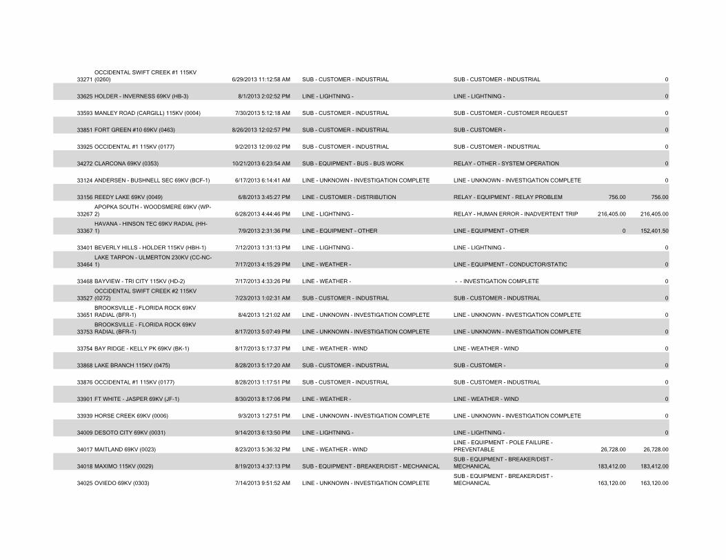
33271OCCIDENTAL SWIFT CREEK #1 115KV (0260) 6/29/2013 11:12:58 AM SUB - CUSTOMER - INDUSTRIAL SUB - CUSTOMER - INDUSTRIAL 0
33625 HOLDER - INVERNESS 69KV (HB-3) 8/1/2013 2:02:52 PM LINE - LIGHTNING - LINE - LIGHTNING - 0
33593 MANLEY ROAD (CARGILL) 115KV (0004) 7/30/2013 5:12:18 AM SUB - CUSTOMER - INDUSTRIAL SUB - CUSTOMER - CUSTOMER REQUEST 0
33851 FORT GREEN #10 69KV (0463) 8/26/2013 12:02:57 PM SUB - CUSTOMER - INDUSTRIAL SUB - CUSTOMER - 0
33925 OCCIDENTAL #1 115KV (0177) 9/2/2013 12:09:02 PM SUB - CUSTOMER - INDUSTRIAL SUB - CUSTOMER - INDUSTRIAL 0
34272 CLARCONA 69KV (0353) 10/21/2013 6:23:54 AM SUB - EQUIPMENT - BUS - BUS WORK RELAY - OTHER - SYSTEM OPERATION 0
33124 ANDERSEN - BUSHNELL SEC 69KV (BCF-1) 6/17/2013 6:14:41 AM LINE - UNKNOWN - INVESTIGATION COMPLETE LINE - UNKNOWN - INVESTIGATION COMPLETE 0
33156 REEDY LAKE 69KV (0049) 6/8/2013 3:45:27 PM LINE - CUSTOMER - DISTRIBUTION RELAY - EQUIPMENT - RELAY PROBLEM 756.00 756.00
33267APOPKA SOUTH - WOODSMERE 69KV (WP-2) 6/28/2013 4:44:46 PM LINE - LIGHTNING - RELAY - HUMAN ERROR - INADVERTENT TRIP 216,405.00 216,405.00
33367HAVANA - HINSON TEC 69KV RADIAL (HH-1) 7/9/2013 2:31:36 PM LINE - EQUIPMENT - OTHER LINE - EQUIPMENT - OTHER 0 152,401.50
33401 BEVERLY HILLS - HOLDER 115KV (HBH-1) 7/12/2013 1:31:13 PM LINE - LIGHTNING - LINE - LIGHTNING - 0
33464LAKE TARPON - ULMERTON 230KV (CC-NC-1) 7/17/2013 4:15:29 PM LINE - WEATHER - LINE - EQUIPMENT - CONDUCTOR/STATIC 0
33468 BAYVIEW - TRI CITY 115KV (HD-2) 7/17/2013 4:33:26 PM LINE - WEATHER - - - INVESTIGATION COMPLETE 0
33527OCCIDENTAL SWIFT CREEK #2 115KV (0272) 7/23/2013 1:02:31 AM SUB - CUSTOMER - INDUSTRIAL SUB - CUSTOMER - INDUSTRIAL 0
33651BROOKSVILLE - FLORIDA ROCK 69KV RADIAL (BFR-1) 8/4/2013 1:21:02 AM LINE - UNKNOWN - INVESTIGATION COMPLETE LINE - UNKNOWN - INVESTIGATION COMPLETE 0
33753BROOKSVILLE - FLORIDA ROCK 69KV RADIAL (BFR-1) 8/17/2013 5:07:49 PM LINE - UNKNOWN - INVESTIGATION COMPLETE LINE - UNKNOWN - INVESTIGATION COMPLETE 0
33754 BAY RIDGE - KELLY PK 69KV (BK-1) 8/17/2013 5:17:37 PM LINE - WEATHER - WIND LINE - WEATHER - WIND 0
33868 LAKE BRANCH 115KV (0475) 8/28/2013 5:17:20 AM SUB - CUSTOMER - INDUSTRIAL SUB - CUSTOMER - 0
33876 OCCIDENTAL #1 115KV (0177) 8/28/2013 1:17:51 PM SUB - CUSTOMER - INDUSTRIAL SUB - CUSTOMER - INDUSTRIAL 0
33901 FT WHITE - JASPER 69KV (JF-1) 8/30/2013 8:17:06 PM LINE - WEATHER - LINE - WEATHER - WIND 0
33939 HORSE CREEK 69KV (0006) 9/3/2013 1:27:51 PM LINE - UNKNOWN - INVESTIGATION COMPLETE LINE - UNKNOWN - INVESTIGATION COMPLETE 0
34009 DESOTO CITY 69KV (0031) 9/14/2013 6:13:50 PM LINE - LIGHTNING - LINE - LIGHTNING - 0
34017 MAITLAND 69KV (0023) 8/23/2013 5:36:32 PM LINE - WEATHER - WINDLINE - EQUIPMENT - POLE FAILURE - PREVENTABLE 26,728.00 26,728.00
34018 MAXIMO 115KV (0029) 8/19/2013 4:37:13 PM SUB - EQUIPMENT - BREAKER/DIST - MECHANICALSUB - EQUIPMENT - BREAKER/DIST - MECHANICAL 183,412.00 183,412.00
34025 OVIEDO 69KV (0303) 7/14/2013 9:51:52 AM LINE - UNKNOWN - INVESTIGATION COMPLETESUB - EQUIPMENT - BREAKER/DIST - MECHANICAL 163,120.00 163,120.00
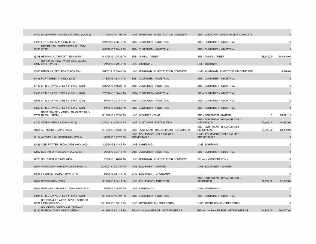
34490 DAVENPORT - HAINES CITY 69KV (ICLW-6) 11/17/2013 6:41:05 AM LINE - UNKNOWN - INVESTIGATION COMPLETE SUB - UNKNOWN - INVESTIGATION COMPLETE 0
32293 FORT GREEN #11 69KV (0472) 2/27/2013 7:28:49 AM SUB - CUSTOMER - INDUSTRIAL SUB - CUSTOMER - INDUSTRIAL 0
33283OCCIDENTAL SWIFT CREEK #2 115KV (0272) 6/30/2013 8:29:41 PM SUB - CUSTOMER - INDUSTRIAL SUB - CUSTOMER - INDUSTRIAL 0
33378 HERNANDO AIRPORT 115KV (0376) 6/30/2013 4:05:28 AM SUB - ANIMAL - OTHER SUB - ANIMAL - OTHER 188,949.00 188,949.00
33947NORTH BARTOW - WEST LAKE WALES 69KV (BWL-2) 9/4/2013 5:20:47 PM LINE - LIGHTNING - LINE - LIGHTNING - 0
33965 UMATILLA (SEC) REA 69KV (6794) 9/6/2013 11:05:43 PM LINE - UNKNOWN - INVESTIGATION COMPLETE LINE - UNKNOWN - INVESTIGATION COMPLETE 3,540.00
34495 FORT GREEN #10 69KV (0463) 11/18/2013 1:58:44 AM SUB - CUSTOMER - INDUSTRIAL SUB - CUSTOMER - INDUSTRIAL 0
33189 LITTLE PAYNE CREEK #1 69KV (0287) 6/22/2013 1:16:20 PM SUB - CUSTOMER - INDUSTRIAL SUB - CUSTOMER - INDUSTRIAL 0
33496 LITTLE PAYNE CREEK #1 69KV (0287) 7/20/2013 6:38:43 AM SUB - CUSTOMER - INDUSTRIAL SUB - CUSTOMER - INDUSTRIAL 0
33628 LITTLE PAYNE CREEK #1 69KV (0287) 8/1/2013 7:23:46 PM SUB - CUSTOMER - INDUSTRIAL SUB - CUSTOMER - INDUSTRIAL 0
33653 LITTLE PAYNE CREEK #1 69KV (0287) 8/4/2013 3:32:50 AM SUB - CUSTOMER - INDUSTRIAL SUB - CUSTOMER - INDUSTRIAL 0
33722ROSS PRAIRIE - MARION OAKS SEC 69KV RADIAL (RPMX-1) 8/13/2013 4:02:36 PM LINE - WEATHER - WIND SUB - EQUIPMENT - SWITCH 0 55,371.10
34797 SEVEN SPRINGS 230KV (0225) 7/25/2013 12:29:25 PM LINE - CUSTOMER - DISTRIBUTIONSUB - EQUIPMENT - BREAKER/DIST - MECHANICAL 40,992.00 40,992.00
34864 ALTAMONTE 230KV (0136) 12/19/2013 8:13:30 AM SUB - EQUIPMENT - BREAKER/DIST - ELECTRICALSUB - EQUIPMENT - BREAKER/DIST - ELECTRICAL 53,900.00 53,900.00
32154 ARCHER - WILLISTON 69KV (AW-1) 1/30/2013 3:47:25 PMLINE - EQUIPMENT - POLE FAILURE - PREVENTABLE
LINE - EQUIPMENT - POLE FAILURE - PREVENTABLE 0
32425 CLEARWATER - HIGHLANDS 69KV (HCL-1) 3/22/2013 8:13:46 PM LINE - LIGHTNING - LINE - LIGHTNING - 0
32697 SOUTH FORT MEADE 115KV (0360) 5/2/2013 6:04:13 PM SUB - CUSTOMER - INDUSTRIAL SUB - CUSTOMER - INDUSTRIAL 0
32750 SOUTH POLK 230KV (0498) 5/6/2013 8:46:07 AM LINE - UNKNOWN - INVESTIGATION COMPLETE RELAY - MISOPERATION - 0
32914 VANDOLAH - WHIDDON 230KV (VWX-1) 5/25/2013 12:33:37 PM LINE - EQUIPMENT - JUMPER LINE - EQUIPMENT - JUMPER 0
33015 FT WHITE - JASPER 69KV (JF-1) 6/6/2013 8:51:44 PM LINE - EQUIPMENT - CROSSARM - - 0
34014 OVIEDO 69KV (0303) 3/19/2013 1:04:11 PM LINE - EQUIPMENT - ARRESTERSUB - EQUIPMENT - BREAKER/DIST - ELECTRICAL 51,639.00 51,639.00
33954 PARKWAY - SHINGLE CREEK 69KV (SCP-1) 9/5/2013 6:00:52 PM LINE - LIGHTNING - LINE - LIGHTNING - 0
33994 LITTLE PAYNE CREEK #1 69KV (0287) 9/12/2013 4:37:07 PM SUB - CUSTOMER - INDUSTRIAL SUB - CUSTOMER - INDUSTRIAL 0
34239BROOKSVILLE WEST - SEVEN SPRINGS 230KV (CRS-CC-1) 10/14/2013 3:03:15 PM LINE - OPERATIONAL - EMERGENCY LINE - OPERATIONAL - EMERGENCY 0
33150HOLOPAW - OSCEOLA PL (RELIANT ENERGY) 230KV HREX1 (HREX-1) 6/19/2013 8:31:49 PM RELAY - HUMAN ERROR - SETTING ERROR RELAY - HUMAN ERROR - SETTING ERROR 194,888.00 304,207.00
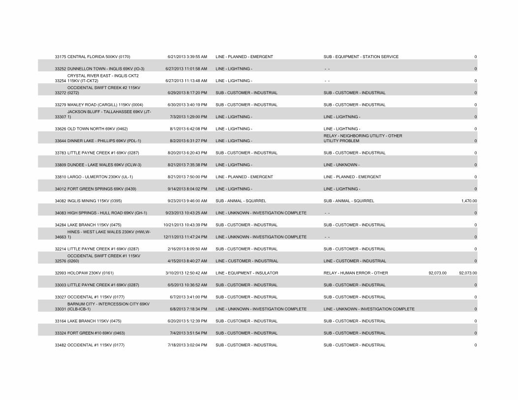
33175 CENTRAL FLORIDA 500KV (0170) 6/21/2013 3:39:55 AM LINE - PLANNED - EMERGENT SUB - EQUIPMENT - STATION SERVICE 0
33252 DUNNELLON TOWN - INGLIS 69KV (IO-3) 6/27/2013 11:01:58 AM LINE - LIGHTNING - - - 0
33254CRYSTAL RIVER EAST - INGLIS CKT2 115KV (IT-CKT2) 6/27/2013 11:13:48 AM LINE - LIGHTNING - - - 0
33272OCCIDENTAL SWIFT CREEK #2 115KV (0272) 6/29/2013 8:17:20 PM SUB - CUSTOMER - INDUSTRIAL SUB - CUSTOMER - INDUSTRIAL 0
33279 MANLEY ROAD (CARGILL) 115KV (0004) 6/30/2013 3:40:19 PM SUB - CUSTOMER - INDUSTRIAL SUB - CUSTOMER - INDUSTRIAL 0
33307JACKSON BLUFF - TALLAHASSEE 69KV (JT-1) 7/3/2013 1:29:00 PM LINE - LIGHTNING - LINE - LIGHTNING - 0
33626 OLD TOWN NORTH 69KV (0462) 8/1/2013 6:42:08 PM LINE - LIGHTNING - LINE - LIGHTNING - 0
33644 DINNER LAKE - PHILLIPS 69KV (PDL-1) 8/2/2013 6:31:27 PM LINE - LIGHTNING - RELAY - NEIGHBORING UTILITY - OTHER UTILITY PROBLEM 0
33783 LITTLE PAYNE CREEK #1 69KV (0287) 8/20/2013 6:20:43 PM SUB - CUSTOMER - INDUSTRIAL SUB - CUSTOMER - INDUSTRIAL 0
33809 DUNDEE - LAKE WALES 69KV (ICLW-3) 8/21/2013 7:35:38 PM LINE - LIGHTNING - LINE - UNKNOWN - 0
33810 LARGO - ULMERTON 230KV (UL-1) 8/21/2013 7:50:00 PM LINE - PLANNED - EMERGENT LINE - PLANNED - EMERGENT 0
34012 FORT GREEN SPRINGS 69KV (0439) 9/14/2013 8:04:02 PM LINE - LIGHTNING - LINE - LIGHTNING - 0
34082 INGLIS MINING 115KV (0395) 9/23/2013 9:46:00 AM SUB - ANIMAL - SQUIRREL SUB - ANIMAL - SQUIRREL 1,470.00
34083 HIGH SPRINGS - HULL ROAD 69KV (GH-1) 9/23/2013 10:43:25 AM LINE - UNKNOWN - INVESTIGATION COMPLETE - - 0
34284 LAKE BRANCH 115KV (0475) 10/21/2013 10:43:39 PM SUB - CUSTOMER - INDUSTRIAL SUB - CUSTOMER - INDUSTRIAL 0
34663HINES - WEST LAKE WALES 230KV (HWLW-1) 12/11/2013 11:47:24 PM LINE - UNKNOWN - INVESTIGATION COMPLETE - - 0
32214 LITTLE PAYNE CREEK #1 69KV (0287) 2/16/2013 8:09:50 AM SUB - CUSTOMER - INDUSTRIAL SUB - CUSTOMER - INDUSTRIAL 0
32576OCCIDENTAL SWIFT CREEK #1 115KV (0260) 4/15/2013 8:40:27 AM LINE - CUSTOMER - INDUSTRIAL LINE - CUSTOMER - INDUSTRIAL 0
32993 HOLOPAW 230KV (0161) 3/10/2013 12:50:42 AM LINE - EQUIPMENT - INSULATOR RELAY - HUMAN ERROR - OTHER 92,073.00 92,073.00
33003 LITTLE PAYNE CREEK #1 69KV (0287) 6/5/2013 10:36:52 AM SUB - CUSTOMER - INDUSTRIAL SUB - CUSTOMER - INDUSTRIAL 0
33027 OCCIDENTAL #1 115KV (0177) 6/7/2013 3:41:00 PM SUB - CUSTOMER - INDUSTRIAL SUB - CUSTOMER - INDUSTRIAL 0
33031BARNUM CITY - INTERCESSION CITY 69KV (ICLB-ICB-1) 6/8/2013 7:18:34 PM LINE - UNKNOWN - INVESTIGATION COMPLETE LINE - UNKNOWN - INVESTIGATION COMPLETE 0
33164 LAKE BRANCH 115KV (0475) 6/20/2013 5:12:39 PM SUB - CUSTOMER - INDUSTRIAL SUB - CUSTOMER - INDUSTRIAL 0
33324 FORT GREEN #10 69KV (0463) 7/4/2013 3:51:54 PM SUB - CUSTOMER - INDUSTRIAL SUB - CUSTOMER - INDUSTRIAL 0
33482 OCCIDENTAL #1 115KV (0177) 7/18/2013 3:02:04 PM SUB - CUSTOMER - INDUSTRIAL SUB - CUSTOMER - INDUSTRIAL 0
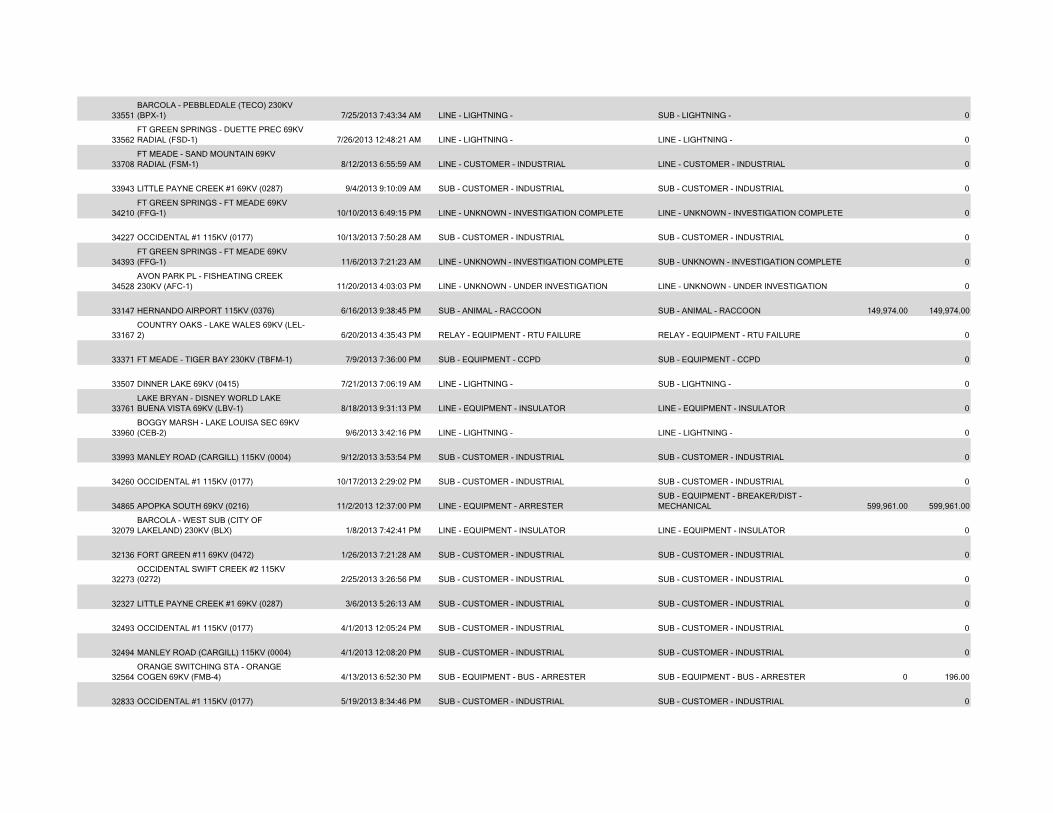
33551BARCOLA - PEBBLEDALE (TECO) 230KV (BPX-1) 7/25/2013 7:43:34 AM LINE - LIGHTNING - SUB - LIGHTNING - 0
33562FT GREEN SPRINGS - DUETTE PREC 69KV RADIAL (FSD-1) 7/26/2013 12:48:21 AM LINE - LIGHTNING - LINE - LIGHTNING - 0
33708FT MEADE - SAND MOUNTAIN 69KV RADIAL (FSM-1) 8/12/2013 6:55:59 AM LINE - CUSTOMER - INDUSTRIAL LINE - CUSTOMER - INDUSTRIAL 0
33943 LITTLE PAYNE CREEK #1 69KV (0287) 9/4/2013 9:10:09 AM SUB - CUSTOMER - INDUSTRIAL SUB - CUSTOMER - INDUSTRIAL 0
34210FT GREEN SPRINGS - FT MEADE 69KV (FFG-1) 10/10/2013 6:49:15 PM LINE - UNKNOWN - INVESTIGATION COMPLETE LINE - UNKNOWN - INVESTIGATION COMPLETE 0
34227 OCCIDENTAL #1 115KV (0177) 10/13/2013 7:50:28 AM SUB - CUSTOMER - INDUSTRIAL SUB - CUSTOMER - INDUSTRIAL 0
34393FT GREEN SPRINGS - FT MEADE 69KV (FFG-1) 11/6/2013 7:21:23 AM LINE - UNKNOWN - INVESTIGATION COMPLETE SUB - UNKNOWN - INVESTIGATION COMPLETE 0
34528AVON PARK PL - FISHEATING CREEK 230KV (AFC-1) 11/20/2013 4:03:03 PM LINE - UNKNOWN - UNDER INVESTIGATION LINE - UNKNOWN - UNDER INVESTIGATION 0
33147 HERNANDO AIRPORT 115KV (0376) 6/16/2013 9:38:45 PM SUB - ANIMAL - RACCOON SUB - ANIMAL - RACCOON 149,974.00 149,974.00
33167COUNTRY OAKS - LAKE WALES 69KV (LEL-2) 6/20/2013 4:35:43 PM RELAY - EQUIPMENT - RTU FAILURE RELAY - EQUIPMENT - RTU FAILURE 0
33371 FT MEADE - TIGER BAY 230KV (TBFM-1) 7/9/2013 7:36:00 PM SUB - EQUIPMENT - CCPD SUB - EQUIPMENT - CCPD 0
33507 DINNER LAKE 69KV (0415) 7/21/2013 7:06:19 AM LINE - LIGHTNING - SUB - LIGHTNING - 0
33761LAKE BRYAN - DISNEY WORLD LAKE BUENA VISTA 69KV (LBV-1) 8/18/2013 9:31:13 PM LINE - EQUIPMENT - INSULATOR LINE - EQUIPMENT - INSULATOR 0
33960BOGGY MARSH - LAKE LOUISA SEC 69KV (CEB-2) 9/6/2013 3:42:16 PM LINE - LIGHTNING - LINE - LIGHTNING - 0
33993 MANLEY ROAD (CARGILL) 115KV (0004) 9/12/2013 3:53:54 PM SUB - CUSTOMER - INDUSTRIAL SUB - CUSTOMER - INDUSTRIAL 0
34260 OCCIDENTAL #1 115KV (0177) 10/17/2013 2:29:02 PM SUB - CUSTOMER - INDUSTRIAL SUB - CUSTOMER - INDUSTRIAL 0
34865 APOPKA SOUTH 69KV (0216) 11/2/2013 12:37:00 PM LINE - EQUIPMENT - ARRESTERSUB - EQUIPMENT - BREAKER/DIST - MECHANICAL 599,961.00 599,961.00
32079BARCOLA - WEST SUB (CITY OF LAKELAND) 230KV (BLX) 1/8/2013 7:42:41 PM LINE - EQUIPMENT - INSULATOR LINE - EQUIPMENT - INSULATOR 0
32136 FORT GREEN #11 69KV (0472) 1/26/2013 7:21:28 AM SUB - CUSTOMER - INDUSTRIAL SUB - CUSTOMER - INDUSTRIAL 0
32273OCCIDENTAL SWIFT CREEK #2 115KV (0272) 2/25/2013 3:26:56 PM SUB - CUSTOMER - INDUSTRIAL SUB - CUSTOMER - INDUSTRIAL 0
32327 LITTLE PAYNE CREEK #1 69KV (0287) 3/6/2013 5:26:13 AM SUB - CUSTOMER - INDUSTRIAL SUB - CUSTOMER - INDUSTRIAL 0
32493 OCCIDENTAL #1 115KV (0177) 4/1/2013 12:05:24 PM SUB - CUSTOMER - INDUSTRIAL SUB - CUSTOMER - INDUSTRIAL 0
32494 MANLEY ROAD (CARGILL) 115KV (0004) 4/1/2013 12:08:20 PM SUB - CUSTOMER - INDUSTRIAL SUB - CUSTOMER - INDUSTRIAL 0
32564ORANGE SWITCHING STA - ORANGE COGEN 69KV (FMB-4) 4/13/2013 6:52:30 PM SUB - EQUIPMENT - BUS - ARRESTER SUB - EQUIPMENT - BUS - ARRESTER 0 196.00
32833 OCCIDENTAL #1 115KV (0177) 5/19/2013 8:34:46 PM SUB - CUSTOMER - INDUSTRIAL SUB - CUSTOMER - INDUSTRIAL 0
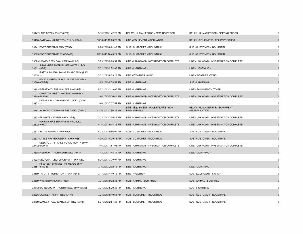
33142 LAKE BRYAN 230KV (0206) 5/10/2013 1:42:20 PM RELAY - HUMAN ERROR - SETTING ERROR RELAY - HUMAN ERROR - SETTING ERROR 0
33178 GATEWAY - ULMERTON 115KV (HD-5) 6/21/2013 12:05:26 PM LINE - EQUIPMENT - INSULATOR RELAY - EQUIPMENT - RELAY PROBLEM 0
33241 FORT GREEN #4 69KV (0335) 6/26/2013 6:01:45 PM SUB - CUSTOMER - INDUSTRIAL SUB - CUSTOMER - INDUSTRIAL 0
33395 FORT GREEN #10 69KV (0463) 7/11/2013 10:43:21 PM SUB - CUSTOMER - INDUSTRIAL SUB - CUSTOMER - INDUSTRIAL 0
33589 HOWEY SEC - OKAHUMPKA (CLL-3) 7/29/2013 9:09:57 PM LINE - UNKNOWN - INVESTIGATION COMPLETE LINE - UNKNOWN - INVESTIGATION COMPLETE 0
33611SUWANNEE RIVER PL - FT WHITE 115KV (SF-2) 7/31/2013 2:52:06 PM LINE - LIGHTNING - LINE - LIGHTNING - 0
33618EUSTIS SOUTH - TAVARES SEC 69KV (EST-1) 7/31/2013 8:29:16 PM LINE - WEATHER - WIND LINE - WEATHER - WIND 0
33666BOGGY MARSH - LAKE LOUISA SEC 69KV (CEB-2) 8/5/2013 9:38:53 PM LINE - LIGHTNING - SUB - LIGHTNING - 0
33803 PIEDMONT - SPRING LAKE 69KV (PSL-1) 8/21/2013 3:19:00 PM LINE - LIGHTNING - LINE - EQUIPMENT - OTHER 0
33949UMERTON WEST - WALSINGHAM 69KV (DLW-6) 9/4/2013 5:36:40 PM LINE - UNKNOWN - INVESTIGATION COMPLETE LINE - UNKNOWN - INVESTIGATION COMPLETE 0
34173DEBARY PL - ORANGE CITY 230KV (DDW-1) 10/6/2013 7:27:58 PM LINE - LIGHTNING - - - 0
34757 AVALON - CLERMONT EAST 69KV (CET-1) 11/26/2013 7:56:25 AMLINE - EQUIPMENT - POLE FAILURE - NON PREVENTABLE
RELAY - HUMAN ERROR - EQUIPMENT MISAPPLICATION 0
32433 FT WHITE - JASPER 69KV (JF-1) 3/23/2013 3:05:47 PM LINE - UNKNOWN - INVESTIGATION COMPLETE LINE - UNKNOWN - INVESTIGATION COMPLETE 0
32572FLORIDA GAS TRANSMISSION 230KV (0512) 4/14/2013 9:07:32 PM LINE - UNKNOWN - INVESTIGATION COMPLETE LINE - UNKNOWN - INVESTIGATION COMPLETE 0
32617 INGLIS MINING 115KV (0395) 4/22/2013 9:56:00 AM SUB - CUSTOMER - INDUSTRIAL SUB - CUSTOMER - INDUSTRIAL 0
32677 LITTLE PAYNE CREEK #1 69KV (0287) 4/30/2013 8:29:43 AM SUB - CUSTOMER - INDUSTRIAL SUB - CUSTOMER - INDUSTRIAL 0
32712DESOTO CITY - LAKE PLACID NORTH 69KV (DLP-1) 5/6/2013 7:51:06 AM LINE - UNKNOWN - INVESTIGATION COMPLETE LINE - UNKNOWN - INVESTIGATION COMPLETE 0
33308 PIEDMONT - PLYMOUTH 69KV (PP-1) 7/3/2013 1:48:37 PM LINE - LIGHTNING - LINE - LIGHTNING - 0
33238 DELTONA - DELTONA EAST 115KV (DED-1) 6/26/2013 3:30:07 PM LINE - LIGHTNING - - - 0
33451FT GREEN SPRINGS - FT MEADE 69KV (FFG-1) 7/16/2013 2:02:42 PM LINE - LIGHTNING - LINE - LIGHTNING - 0
33469 TRI CITY - ULMERTON 115KV (HD-8) 7/17/2013 4:49:16 PM LINE - WEATHER - SUB - EQUIPMENT - SWITCH 0
33509 WINTER PARK 69KV (0305) 7/21/2013 9:32:35 AM SUB - ANIMAL - SQUIRREL SUB - ANIMAL - SQUIRREL 0
33513 BARNUM CITY - NORTHRIDGE 69KV (BCN) 7/21/2013 5:20:36 PM LINE - LIGHTNING - SUB - LIGHTNING - 0
33536 OCCIDENTAL #1 115KV (0177) 7/24/2013 8:10:54 AM SUB - CUSTOMER - INDUSTRIAL SUB - CUSTOMER - INDUSTRIAL 0
33799 MANLEY ROAD (CARGILL) 115KV (0004) 8/21/2013 2:54:38 PM SUB - CUSTOMER - INDUSTRIAL SUB - CUSTOMER - INDUSTRIAL 0
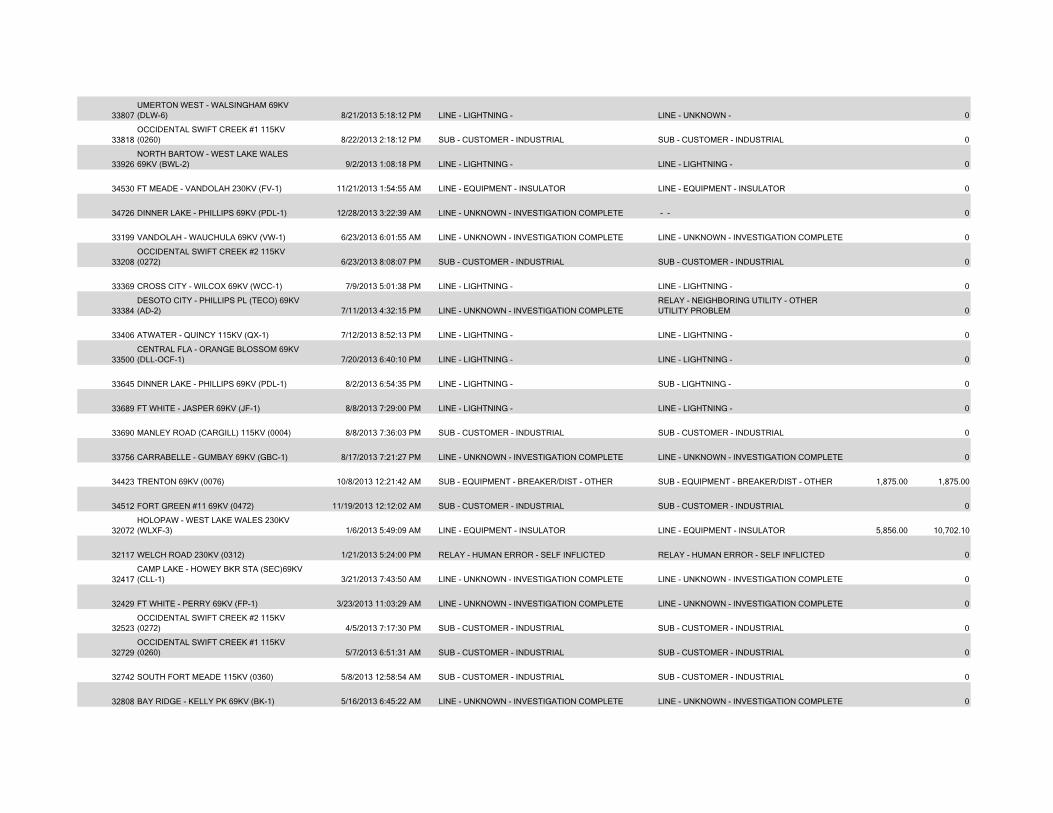
33807UMERTON WEST - WALSINGHAM 69KV (DLW-6) 8/21/2013 5:18:12 PM LINE - LIGHTNING - LINE - UNKNOWN - 0
33818OCCIDENTAL SWIFT CREEK #1 115KV (0260) 8/22/2013 2:18:12 PM SUB - CUSTOMER - INDUSTRIAL SUB - CUSTOMER - INDUSTRIAL 0
33926NORTH BARTOW - WEST LAKE WALES 69KV (BWL-2) 9/2/2013 1:08:18 PM LINE - LIGHTNING - LINE - LIGHTNING - 0
34530 FT MEADE - VANDOLAH 230KV (FV-1) 11/21/2013 1:54:55 AM LINE - EQUIPMENT - INSULATOR LINE - EQUIPMENT - INSULATOR 0
34726 DINNER LAKE - PHILLIPS 69KV (PDL-1) 12/28/2013 3:22:39 AM LINE - UNKNOWN - INVESTIGATION COMPLETE - - 0
33199 VANDOLAH - WAUCHULA 69KV (VW-1) 6/23/2013 6:01:55 AM LINE - UNKNOWN - INVESTIGATION COMPLETE LINE - UNKNOWN - INVESTIGATION COMPLETE 0
33208OCCIDENTAL SWIFT CREEK #2 115KV (0272) 6/23/2013 8:08:07 PM SUB - CUSTOMER - INDUSTRIAL SUB - CUSTOMER - INDUSTRIAL 0
33369 CROSS CITY - WILCOX 69KV (WCC-1) 7/9/2013 5:01:38 PM LINE - LIGHTNING - LINE - LIGHTNING - 0
33384DESOTO CITY - PHILLIPS PL (TECO) 69KV (AD-2) 7/11/2013 4:32:15 PM LINE - UNKNOWN - INVESTIGATION COMPLETE
RELAY - NEIGHBORING UTILITY - OTHER UTILITY PROBLEM 0
33406 ATWATER - QUINCY 115KV (QX-1) 7/12/2013 8:52:13 PM LINE - LIGHTNING - LINE - LIGHTNING - 0
33500CENTRAL FLA - ORANGE BLOSSOM 69KV (DLL-OCF-1) 7/20/2013 6:40:10 PM LINE - LIGHTNING - LINE - LIGHTNING - 0
33645 DINNER LAKE - PHILLIPS 69KV (PDL-1) 8/2/2013 6:54:35 PM LINE - LIGHTNING - SUB - LIGHTNING - 0
33689 FT WHITE - JASPER 69KV (JF-1) 8/8/2013 7:29:00 PM LINE - LIGHTNING - LINE - LIGHTNING - 0
33690 MANLEY ROAD (CARGILL) 115KV (0004) 8/8/2013 7:36:03 PM SUB - CUSTOMER - INDUSTRIAL SUB - CUSTOMER - INDUSTRIAL 0
33756 CARRABELLE - GUMBAY 69KV (GBC-1) 8/17/2013 7:21:27 PM LINE - UNKNOWN - INVESTIGATION COMPLETE LINE - UNKNOWN - INVESTIGATION COMPLETE 0
34423 TRENTON 69KV (0076) 10/8/2013 12:21:42 AM SUB - EQUIPMENT - BREAKER/DIST - OTHER SUB - EQUIPMENT - BREAKER/DIST - OTHER 1,875.00 1,875.00
34512 FORT GREEN #11 69KV (0472) 11/19/2013 12:12:02 AM SUB - CUSTOMER - INDUSTRIAL SUB - CUSTOMER - INDUSTRIAL 0
32072HOLOPAW - WEST LAKE WALES 230KV (WLXF-3) 1/6/2013 5:49:09 AM LINE - EQUIPMENT - INSULATOR LINE - EQUIPMENT - INSULATOR 5,856.00 10,702.10
32117 WELCH ROAD 230KV (0312) 1/21/2013 5:24:00 PM RELAY - HUMAN ERROR - SELF INFLICTED RELAY - HUMAN ERROR - SELF INFLICTED 0
32417CAMP LAKE - HOWEY BKR STA (SEC)69KV (CLL-1) 3/21/2013 7:43:50 AM LINE - UNKNOWN - INVESTIGATION COMPLETE LINE - UNKNOWN - INVESTIGATION COMPLETE 0
32429 FT WHITE - PERRY 69KV (FP-1) 3/23/2013 11:03:29 AM LINE - UNKNOWN - INVESTIGATION COMPLETE LINE - UNKNOWN - INVESTIGATION COMPLETE 0
32523OCCIDENTAL SWIFT CREEK #2 115KV (0272) 4/5/2013 7:17:30 PM SUB - CUSTOMER - INDUSTRIAL SUB - CUSTOMER - INDUSTRIAL 0
32729OCCIDENTAL SWIFT CREEK #1 115KV (0260) 5/7/2013 6:51:31 AM SUB - CUSTOMER - INDUSTRIAL SUB - CUSTOMER - INDUSTRIAL 0
32742 SOUTH FORT MEADE 115KV (0360) 5/8/2013 12:58:54 AM SUB - CUSTOMER - INDUSTRIAL SUB - CUSTOMER - INDUSTRIAL 0
32808 BAY RIDGE - KELLY PK 69KV (BK-1) 5/16/2013 6:45:22 AM LINE - UNKNOWN - INVESTIGATION COMPLETE LINE - UNKNOWN - INVESTIGATION COMPLETE 0
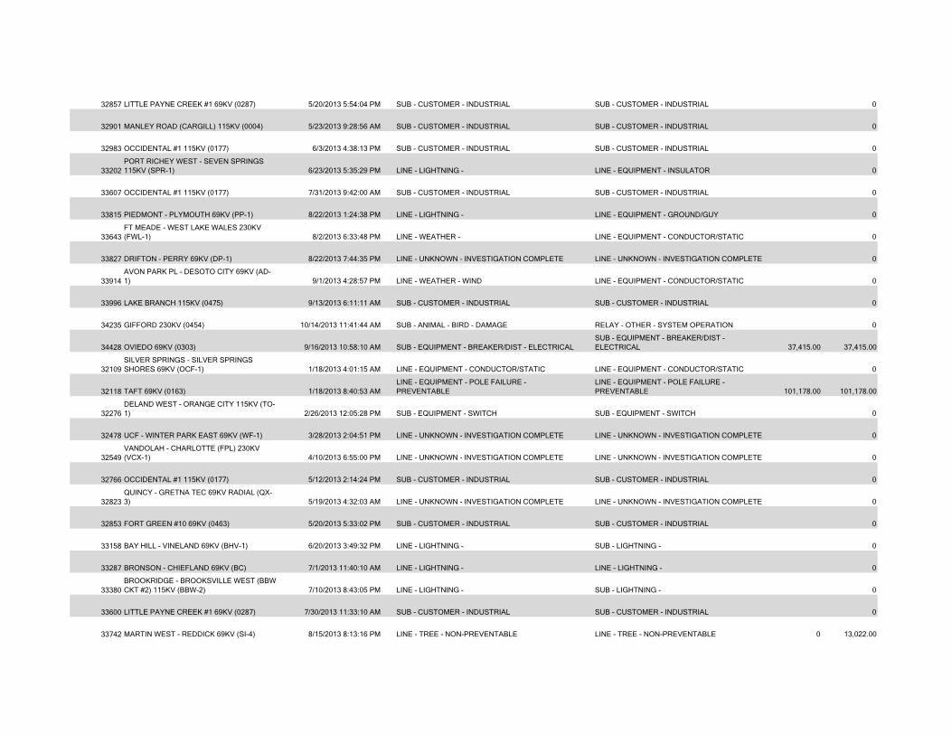
32857 LITTLE PAYNE CREEK #1 69KV (0287) 5/20/2013 5:54:04 PM SUB - CUSTOMER - INDUSTRIAL SUB - CUSTOMER - INDUSTRIAL 0
32901 MANLEY ROAD (CARGILL) 115KV (0004) 5/23/2013 9:28:56 AM SUB - CUSTOMER - INDUSTRIAL SUB - CUSTOMER - INDUSTRIAL 0
32983 OCCIDENTAL #1 115KV (0177) 6/3/2013 4:38:13 PM SUB - CUSTOMER - INDUSTRIAL SUB - CUSTOMER - INDUSTRIAL 0
33202PORT RICHEY WEST - SEVEN SPRINGS 115KV (SPR-1) 6/23/2013 5:35:29 PM LINE - LIGHTNING - LINE - EQUIPMENT - INSULATOR 0
33607 OCCIDENTAL #1 115KV (0177) 7/31/2013 9:42:00 AM SUB - CUSTOMER - INDUSTRIAL SUB - CUSTOMER - INDUSTRIAL 0
33815 PIEDMONT - PLYMOUTH 69KV (PP-1) 8/22/2013 1:24:38 PM LINE - LIGHTNING - LINE - EQUIPMENT - GROUND/GUY 0
33643FT MEADE - WEST LAKE WALES 230KV (FWL-1) 8/2/2013 6:33:48 PM LINE - WEATHER - LINE - EQUIPMENT - CONDUCTOR/STATIC 0
33827 DRIFTON - PERRY 69KV (DP-1) 8/22/2013 7:44:35 PM LINE - UNKNOWN - INVESTIGATION COMPLETE LINE - UNKNOWN - INVESTIGATION COMPLETE 0
33914AVON PARK PL - DESOTO CITY 69KV (AD-1) 9/1/2013 4:28:57 PM LINE - WEATHER - WIND LINE - EQUIPMENT - CONDUCTOR/STATIC 0
33996 LAKE BRANCH 115KV (0475) 9/13/2013 6:11:11 AM SUB - CUSTOMER - INDUSTRIAL SUB - CUSTOMER - INDUSTRIAL 0
34235 GIFFORD 230KV (0454) 10/14/2013 11:41:44 AM SUB - ANIMAL - BIRD - DAMAGE RELAY - OTHER - SYSTEM OPERATION 0
34428 OVIEDO 69KV (0303) 9/16/2013 10:58:10 AM SUB - EQUIPMENT - BREAKER/DIST - ELECTRICALSUB - EQUIPMENT - BREAKER/DIST - ELECTRICAL 37,415.00 37,415.00
32109SILVER SPRINGS - SILVER SPRINGS SHORES 69KV (OCF-1) 1/18/2013 4:01:15 AM LINE - EQUIPMENT - CONDUCTOR/STATIC LINE - EQUIPMENT - CONDUCTOR/STATIC 0
32118 TAFT 69KV (0163) 1/18/2013 8:40:53 AMLINE - EQUIPMENT - POLE FAILURE - PREVENTABLE
LINE - EQUIPMENT - POLE FAILURE - PREVENTABLE 101,178.00 101,178.00
32276DELAND WEST - ORANGE CITY 115KV (TO-1) 2/26/2013 12:05:28 PM SUB - EQUIPMENT - SWITCH SUB - EQUIPMENT - SWITCH 0
32478 UCF - WINTER PARK EAST 69KV (WF-1) 3/28/2013 2:04:51 PM LINE - UNKNOWN - INVESTIGATION COMPLETE LINE - UNKNOWN - INVESTIGATION COMPLETE 0
32549VANDOLAH - CHARLOTTE (FPL) 230KV (VCX-1) 4/10/2013 6:55:00 PM LINE - UNKNOWN - INVESTIGATION COMPLETE LINE - UNKNOWN - INVESTIGATION COMPLETE 0
32766 OCCIDENTAL #1 115KV (0177) 5/12/2013 2:14:24 PM SUB - CUSTOMER - INDUSTRIAL SUB - CUSTOMER - INDUSTRIAL 0
32823QUINCY - GRETNA TEC 69KV RADIAL (QX-3) 5/19/2013 4:32:03 AM LINE - UNKNOWN - INVESTIGATION COMPLETE LINE - UNKNOWN - INVESTIGATION COMPLETE 0
32853 FORT GREEN #10 69KV (0463) 5/20/2013 5:33:02 PM SUB - CUSTOMER - INDUSTRIAL SUB - CUSTOMER - INDUSTRIAL 0
33158 BAY HILL - VINELAND 69KV (BHV-1) 6/20/2013 3:49:32 PM LINE - LIGHTNING - SUB - LIGHTNING - 0
33287 BRONSON - CHIEFLAND 69KV (BC) 7/1/2013 11:40:10 AM LINE - LIGHTNING - LINE - LIGHTNING - 0
33380BROOKRIDGE - BROOKSVILLE WEST (BBW CKT #2) 115KV (BBW-2) 7/10/2013 8:43:05 PM LINE - LIGHTNING - SUB - LIGHTNING - 0
33600 LITTLE PAYNE CREEK #1 69KV (0287) 7/30/2013 11:33:10 AM SUB - CUSTOMER - INDUSTRIAL SUB - CUSTOMER - INDUSTRIAL 0
33742 MARTIN WEST - REDDICK 69KV (SI-4) 8/15/2013 8:13:16 PM LINE - TREE - NON-PREVENTABLE LINE - TREE - NON-PREVENTABLE 0 13,022.00
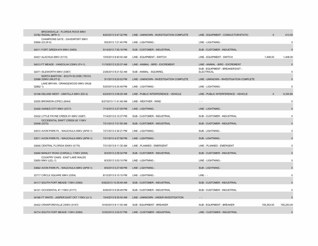
33782BROOKSVILLE - FLORIDA ROCK 69KV RADIAL (BFR-1) 8/20/2013 5:47:32 PM LINE - UNKNOWN - INVESTIGATION COMPLETE LINE - EQUIPMENT - CONDUCTOR/STATIC 0 413.00
33956CHAMPIONS GATE - DAVENPORT 69KV (ICLW-5) 9/5/2013 7:21:40 PM LINE - LIGHTNING - LINE - LIGHTNING - 0
34011 FORT GREEN #10 69KV (0463) 9/14/2013 7:55:19 PM SUB - CUSTOMER - INDUSTRIAL SUB - CUSTOMER - INDUSTRIAL 0
34427 ALACHUA 69KV (0110) 10/5/2013 8:40:00 AM LINE - EQUIPMENT - SWITCH LINE - EQUIPMENT - SWITCH 1,408.00 1,408.00
34513 FT MEADE - VANDOLAH 230KV (FV-1) 11/19/2013 5:25:37 AM LINE - ANIMAL - BIRD - EXCREMENT LINE - ANIMAL - BIRD - EXCREMENT 0
32471 ISLEWORTH 69KV (0387) 2/28/2013 8:21:52 AM SUB - ANIMAL - SQUIRRELSUB - EQUIPMENT - BREAKER/DIST - ELECTRICAL 0
32688NORTH BARTOW - SOUTH ELOISE (TECO) 230KV (WLXT-2) 5/1/2013 8:20:02 PM LINE - UNKNOWN - INVESTIGATION COMPLETE LINE - UNKNOWN - INVESTIGATION COMPLETE 0
32862LAKE BRYAN - ORANGEWOOD 69KV (WLB-1) 5/20/2013 6:24:49 PM LINE - LIGHTNING - LINE - LIGHTNING - 0
33198 DELAND WEST - UMATILLA 69KV (ED-2) 6/23/2013 2:08:25 AM LINE - PUBLIC INTERFERENCE - VEHICLE LINE - PUBLIC INTERFERENCE - VEHICLE 0 6,330.80
33255 BRONSON (CFEC) (6044) 6/27/2013 11:41:46 AM LINE - WEATHER - WIND - - 0
33426 HAINES CITY 69KV (0317) 7/14/2013 3:27:09 PM LINE - LIGHTNING - LINE - LIGHTNING - 0
33432 LITTLE PAYNE CREEK #1 69KV (0287) 7/14/2013 6:12:37 PM SUB - CUSTOMER - INDUSTRIAL SUB - CUSTOMER - INDUSTRIAL 0
33508OCCIDENTAL SWIFT CREEK #2 115KV (0272) 7/21/2013 7:01:55 AM SUB - CUSTOMER - INDUSTRIAL SUB - CUSTOMER - INDUSTRIAL 0
33510 AVON PARK PL - WAUCHULA 69KV (APW-1) 7/21/2013 4:34:21 PM LINE - LIGHTNING - SUB - LIGHTNING - 0
33511 AVON PARK PL - WAUCHULA 69KV (APW-1) 7/21/2013 4:37:58 PM LINE - LIGHTNING - SUB - LIGHTNING - 0
33606 CENTRAL FLORIDA 500KV (0170) 7/31/2013 8:11:35 AM LINE - PLANNED - EMERGENT LINE - PLANNED - EMERGENT 0
33649 MANLEY ROAD (CARGILL) 115KV (0004) 8/3/2013 2:29:34 PM SUB - CUSTOMER - INDUSTRIAL SUB - CUSTOMER - INDUSTRIAL 0
33650COUNTRY OAKS - EAST LAKE WALES 69KV (LEL-1) 8/3/2013 3:03:10 PM LINE - LIGHTNING - LINE - LIGHTNING - 0
33662 AVON PARK PL - WAUCHULA 69KV (APW-1) 8/5/2013 5:27:48 PM LINE - LIGHTNING - SUB - LIGHTNING - 0
33717 CIRCLE SQUARE 69KV (0354) 8/12/2013 9:10:10 PM LINE - LIGHTNING - LINE - - 0
34117 SOUTH FORT MEADE 115KV (0360) 9/26/2013 10:35:49 AM SUB - CUSTOMER - INDUSTRIAL SUB - CUSTOMER - INDUSTRIAL 0
34121 OCCIDENTAL #1 115KV (0177) 9/26/2013 9:29:49 PM SUB - CUSTOMER - INDUSTRIAL SUB - CUSTOMER - INDUSTRIAL 0
34166 FT WHITE - JASPER EAST CKT 115KV (IJ-1) 10/4/2013 8:30:00 AM LINE - UNKNOWN - UNDER INVESTIGATION - - 0
34422 CRAWFORDVILLE 230KV (0147) 10/30/2013 8:11:00 AM SUB - EQUIPMENT - BREAKER SUB - EQUIPMENT - BREAKER 155,253.00 155,253.00
34714 SOUTH FORT MEADE 115KV (0360) 12/20/2013 3:05:57 PM LINE - CUSTOMER - INDUSTRIAL LINE - CUSTOMER - INDUSTRIAL 0
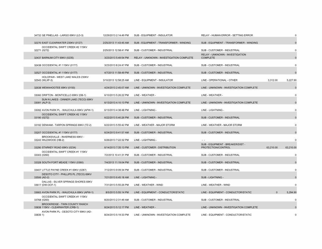
34732 GE PINELLAS - LARGO 69KV (LD-3) 12/29/2013 2:14:49 PM SUB - EQUIPMENT - INSULATOR RELAY - HUMAN ERROR - SETTING ERROR 0
32270 EAST CLEARWATER 230KV (0127) 2/25/2013 11:43:45 AM SUB - EQUIPMENT - TRANSFORMER - WINDING SUB - EQUIPMENT - TRANSFORMER - WINDING 0
32271OCCIDENTAL SWIFT CREEK #2 115KV (0272) 2/25/2013 12:58:41 PM SUB - CUSTOMER - INDUSTRIAL SUB - CUSTOMER - INDUSTRIAL 0
32437 BARNUM CITY 69KV (0235) 3/23/2013 5:49:54 PM RELAY - UNKNOWN - INVESTIGATION COMPLETERELAY - UNKNOWN - INVESTIGATION COMPLETE 0
32438 OCCIDENTAL #1 115KV (0177) 3/23/2013 8:24:47 PM SUB - CUSTOMER - INDUSTRIAL SUB - CUSTOMER - INDUSTRIAL 0
32527 OCCIDENTAL #1 115KV (0177) 4/7/2013 11:58:49 PM SUB - CUSTOMER - INDUSTRIAL SUB - CUSTOMER - INDUSTRIAL 0
32543HOLOPAW - WEST LAKE WALES 230KV (WLXF-3) 3/10/2013 12:58:25 AM LINE - EQUIPMENT - INSULATOR LINE - OPERATIONAL - OTHER 3,312.00 5,227.90
32638 WEWAHOOTEE 69KV (0150) 4/24/2013 2:45:07 AM LINE - UNKNOWN - INVESTIGATION COMPLETE LINE - UNKNOWN - INVESTIGATION COMPLETE 0
33060 DRIFTON - MONTICELLO 69KV (DB-1) 6/10/2013 5:26:22 PM LINE - WEATHER - LINE - WEATHER - 0
33091SUN N LAKES - DINNER LAKE (TECO) 69KV (ALP-3) 6/13/2013 4:10:13 PM LINE - UNKNOWN - INVESTIGATION COMPLETE LINE - UNKNOWN - INVESTIGATION COMPLETE 0
33092 AVON PARK PL - WAUCHULA 69KV (APW-1) 6/13/2013 4:38:48 PM LINE - LIGHTNING - LINE - LIGHTNING - 0
33190OCCIDENTAL SWIFT CREEK #2 115KV (0272) 6/22/2013 5:40:26 PM SUB - CUSTOMER - INDUSTRIAL SUB - CUSTOMER - INDUSTRIAL 0
33192 DENHAM - TARPON SPRINGS 69KV (TZ-2) 6/22/2013 5:55:42 PM LINE - WEATHER - MAJOR STORM LINE - WEATHER - MAJOR STORM 0
33207 OCCIDENTAL #1 115KV (0177) 6/24/2013 9:41:57 AM SUB - CUSTOMER - INDUSTRIAL SUB - CUSTOMER - INDUSTRIAL 0
33243BROOKSVILLE - INVERNESS 69KV - WILDWOOD (HB-2) 6/26/2013 7:22:32 PM LINE - LIGHTNING - - - 0
33290 STARKEY ROAD 69KV (0234) 6/14/2013 7:35:13 PM LINE - CUSTOMER - DISTRIBUTIONSUB - EQUIPMENT - BREAKER/DIST - PROTECTION/CONTROL 63,210.00 63,210.00
33303OCCIDENTAL SWIFT CREEK #1 115KV (0260) 7/2/2013 10:41:31 PM SUB - CUSTOMER - INDUSTRIAL SUB - CUSTOMER - INDUSTRIAL 0
33328 SOUTH FORT MEADE 115KV (0360) 7/4/2013 11:19:04 PM SUB - CUSTOMER - INDUSTRIAL SUB - CUSTOMER - INDUSTRIAL 0
33407 LITTLE PAYNE CREEK #1 69KV (0287) 7/12/2013 9:09:34 PM SUB - CUSTOMER - INDUSTRIAL SUB - CUSTOMER - INDUSTRIAL 0
33506DESOTO CITY - PHILLIPS PL (TECO) 69KV (AD-2) 7/21/2013 6:45:18 AM LINE - LIGHTNING - SUB - LIGHTNING - 0
33617DALLAS - SILVER SPRINGS SHORES 69KV (DW-OCF-1) 7/31/2013 5:55:26 PM LINE - WEATHER - WIND LINE - WEATHER - WIND 0
33663 AVON PARK PL - WAUCHULA 69KV (APW-1) 8/5/2013 5:55:14 PM LINE - EQUIPMENT - CONDUCTOR/STATIC LINE - EQUIPMENT - CONDUCTOR/STATIC 0 5,294.90
33768OCCIDENTAL SWIFT CREEK #1 115KV (0260) 8/20/2013 2:31:49 AM SUB - CUSTOMER - INDUSTRIAL SUB - CUSTOMER - INDUSTRIAL 0
33838BROOKRIDGE - TWIN COUNTY RANCH 115KV - CLEARWATER (CRB-1) 8/24/2013 5:12:17 PM LINE - WEATHER - LINE - UNKNOWN - INVESTIGATION COMPLETE 0
33839AVON PARK PL - DESOTO CITY 69KV (AD-1) 8/24/2013 5:19:33 PM LINE - UNKNOWN - INVESTIGATION COMPLETE LINE - EQUIPMENT - CONDUCTOR/STATIC 0
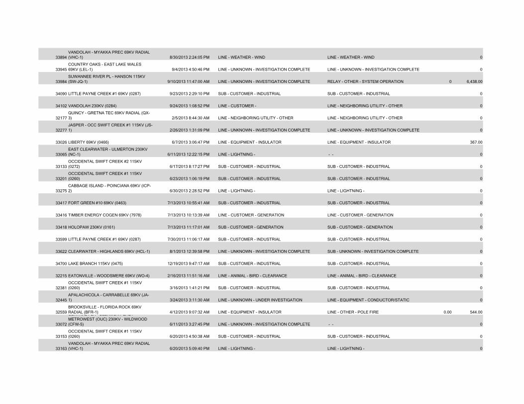
33894VANDOLAH - MYAKKA PREC 69KV RADIAL (VHC-1) 8/30/2013 2:24:05 PM LINE - WEATHER - WIND LINE - WEATHER - WIND 0
33945COUNTRY OAKS - EAST LAKE WALES 69KV (LEL-1) 9/4/2013 4:50:46 PM LINE - UNKNOWN - INVESTIGATION COMPLETE LINE - UNKNOWN - INVESTIGATION COMPLETE 0
33984SUWANNEE RIVER PL - HANSON 115KV (SW-JQ-1) 9/10/2013 11:47:00 AM LINE - UNKNOWN - INVESTIGATION COMPLETE RELAY - OTHER - SYSTEM OPERATION 0 6,438.00
34090 LITTLE PAYNE CREEK #1 69KV (0287) 9/23/2013 2:29:10 PM SUB - CUSTOMER - INDUSTRIAL SUB - CUSTOMER - INDUSTRIAL 0
34102 VANDOLAH 230KV (0284) 9/24/2013 1:08:52 PM LINE - CUSTOMER - LINE - NEIGHBORING UTILITY - OTHER 0
32177QUINCY - GRETNA TEC 69KV RADIAL (QX-3) 2/5/2013 8:44:30 AM LINE - NEIGHBORING UTILITY - OTHER LINE - NEIGHBORING UTILITY - OTHER 0
32277JASPER - OCC SWIFT CREEK #1 115KV (JS-1) 2/26/2013 1:31:09 PM LINE - UNKNOWN - INVESTIGATION COMPLETE LINE - UNKNOWN - INVESTIGATION COMPLETE 0
33026 LIBERTY 69KV (0466) 6/7/2013 3:06:47 PM LINE - EQUIPMENT - INSULATOR LINE - EQUIPMENT - INSULATOR 367.00
33065EAST CLEARWATER - ULMERTON 230KV (NC-1) 6/11/2013 12:22:15 PM LINE - LIGHTNING - - - 0
33133OCCIDENTAL SWIFT CREEK #2 115KV (0272) 6/17/2013 8:17:27 PM SUB - CUSTOMER - INDUSTRIAL SUB - CUSTOMER - INDUSTRIAL 0
33201OCCIDENTAL SWIFT CREEK #1 115KV (0260) 6/23/2013 1:06:19 PM SUB - CUSTOMER - INDUSTRIAL SUB - CUSTOMER - INDUSTRIAL 0
33275CABBAGE ISLAND - POINCIANA 69KV (ICP-2) 6/30/2013 2:28:52 PM LINE - LIGHTNING - LINE - LIGHTNING - 0
33417 FORT GREEN #10 69KV (0463) 7/13/2013 10:55:41 AM SUB - CUSTOMER - INDUSTRIAL SUB - CUSTOMER - INDUSTRIAL 0
33416 TIMBER ENERGY COGEN 69KV (7978) 7/13/2013 10:13:39 AM LINE - CUSTOMER - GENERATION LINE - CUSTOMER - GENERATION 0
33418 HOLOPAW 230KV (0161) 7/13/2013 11:17:01 AM SUB - CUSTOMER - GENERATION SUB - CUSTOMER - GENERATION 0
33599 LITTLE PAYNE CREEK #1 69KV (0287) 7/30/2013 11:06:17 AM SUB - CUSTOMER - INDUSTRIAL SUB - CUSTOMER - INDUSTRIAL 0
33622 CLEARWATER - HIGHLANDS 69KV (HCL-1) 8/1/2013 12:39:58 PM LINE - UNKNOWN - INVESTIGATION COMPLETE SUB - UNKNOWN - INVESTIGATION COMPLETE 0
34700 LAKE BRANCH 115KV (0475) 12/19/2013 9:47:17 AM SUB - CUSTOMER - INDUSTRIAL SUB - CUSTOMER - INDUSTRIAL 0
32215 EATONVILLE - WOODSMERE 69KV (WO-4) 2/16/2013 11:51:16 AM LINE - ANIMAL - BIRD - CLEARANCE LINE - ANIMAL - BIRD - CLEARANCE 0
32381OCCIDENTAL SWIFT CREEK #1 115KV (0260) 3/16/2013 1:41:21 PM SUB - CUSTOMER - INDUSTRIAL SUB - CUSTOMER - INDUSTRIAL 0
32445APALACHICOLA - CARRABELLE 69KV (JA-1) 3/24/2013 3:11:30 AM LINE - UNKNOWN - UNDER INVESTIGATION LINE - EQUIPMENT - CONDUCTOR/STATIC 0
32559BROOKSVILLE - FLORIDA ROCK 69KV RADIAL (BFR-1) 4/12/2013 9:07:32 AM LINE - EQUIPMENT - INSULATOR LINE - OTHER - POLE FIRE 0.00 544.00
33072
CENTRAL FLA CLERMONT EAST METROWEST (OUC) 230KV - WILDWOOD (CFW-5) 6/11/2013 3:27:45 PM LINE - UNKNOWN - INVESTIGATION COMPLETE - - 0
33153OCCIDENTAL SWIFT CREEK #1 115KV (0260) 6/20/2013 4:50:38 AM SUB - CUSTOMER - INDUSTRIAL SUB - CUSTOMER - INDUSTRIAL 0
33163VANDOLAH - MYAKKA PREC 69KV RADIAL (VHC-1) 6/20/2013 5:09:40 PM LINE - LIGHTNING - LINE - LIGHTNING - 0
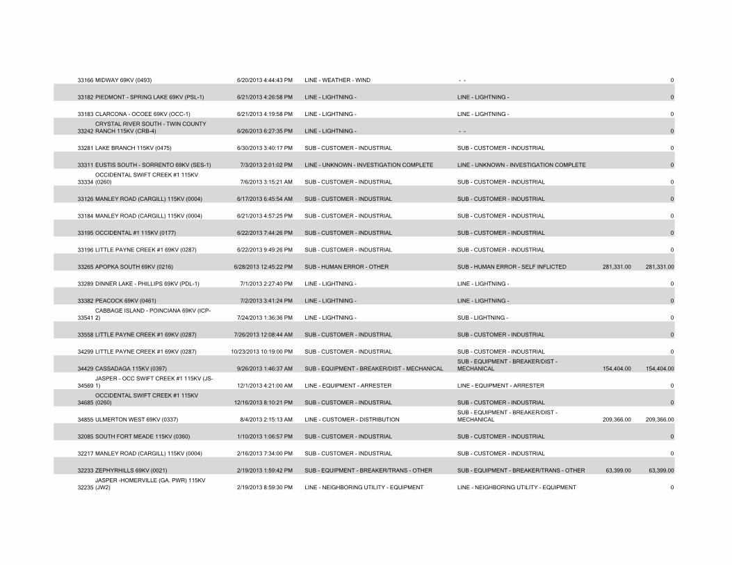
33166 MIDWAY 69KV (0493) 6/20/2013 4:44:43 PM LINE - WEATHER - WIND - - 0
33182 PIEDMONT - SPRING LAKE 69KV (PSL-1) 6/21/2013 4:26:58 PM LINE - LIGHTNING - LINE - LIGHTNING - 0
33183 CLARCONA - OCOEE 69KV (OCC-1) 6/21/2013 4:19:58 PM LINE - LIGHTNING - LINE - LIGHTNING - 0
33242CRYSTAL RIVER SOUTH - TWIN COUNTY RANCH 115KV (CRB-4) 6/26/2013 6:27:35 PM LINE - LIGHTNING - - - 0
33281 LAKE BRANCH 115KV (0475) 6/30/2013 3:40:17 PM SUB - CUSTOMER - INDUSTRIAL SUB - CUSTOMER - INDUSTRIAL 0
33311 EUSTIS SOUTH - SORRENTO 69KV (SES-1) 7/3/2013 2:01:02 PM LINE - UNKNOWN - INVESTIGATION COMPLETE LINE - UNKNOWN - INVESTIGATION COMPLETE 0
33334OCCIDENTAL SWIFT CREEK #1 115KV (0260) 7/6/2013 3:15:21 AM SUB - CUSTOMER - INDUSTRIAL SUB - CUSTOMER - INDUSTRIAL 0
33126 MANLEY ROAD (CARGILL) 115KV (0004) 6/17/2013 6:45:54 AM SUB - CUSTOMER - INDUSTRIAL SUB - CUSTOMER - INDUSTRIAL 0
33184 MANLEY ROAD (CARGILL) 115KV (0004) 6/21/2013 4:57:25 PM SUB - CUSTOMER - INDUSTRIAL SUB - CUSTOMER - INDUSTRIAL 0
33195 OCCIDENTAL #1 115KV (0177) 6/22/2013 7:44:26 PM SUB - CUSTOMER - INDUSTRIAL SUB - CUSTOMER - INDUSTRIAL 0
33196 LITTLE PAYNE CREEK #1 69KV (0287) 6/22/2013 9:49:26 PM SUB - CUSTOMER - INDUSTRIAL SUB - CUSTOMER - INDUSTRIAL 0
33265 APOPKA SOUTH 69KV (0216) 6/28/2013 12:45:22 PM SUB - HUMAN ERROR - OTHER SUB - HUMAN ERROR - SELF INFLICTED 281,331.00 281,331.00
33289 DINNER LAKE - PHILLIPS 69KV (PDL-1) 7/1/2013 2:27:40 PM LINE - LIGHTNING - LINE - LIGHTNING - 0
33382 PEACOCK 69KV (0461) 7/2/2013 3:41:24 PM LINE - LIGHTNING - LINE - LIGHTNING - 0
33541CABBAGE ISLAND - POINCIANA 69KV (ICP-2) 7/24/2013 1:36:36 PM LINE - LIGHTNING - SUB - LIGHTNING - 0
33558 LITTLE PAYNE CREEK #1 69KV (0287) 7/26/2013 12:08:44 AM SUB - CUSTOMER - INDUSTRIAL SUB - CUSTOMER - INDUSTRIAL 0
34299 LITTLE PAYNE CREEK #1 69KV (0287) 10/23/2013 10:19:00 PM SUB - CUSTOMER - INDUSTRIAL SUB - CUSTOMER - INDUSTRIAL 0
34429 CASSADAGA 115KV (0397) 9/26/2013 1:46:37 AM SUB - EQUIPMENT - BREAKER/DIST - MECHANICALSUB - EQUIPMENT - BREAKER/DIST - MECHANICAL 154,404.00 154,404.00
34569JASPER - OCC SWIFT CREEK #1 115KV (JS-1) 12/1/2013 4:21:00 AM LINE - EQUIPMENT - ARRESTER LINE - EQUIPMENT - ARRESTER 0
34685OCCIDENTAL SWIFT CREEK #1 115KV (0260) 12/16/2013 8:10:21 PM SUB - CUSTOMER - INDUSTRIAL SUB - CUSTOMER - INDUSTRIAL 0
34855 ULMERTON WEST 69KV (0337) 8/4/2013 2:15:13 AM LINE - CUSTOMER - DISTRIBUTIONSUB - EQUIPMENT - BREAKER/DIST - MECHANICAL 209,366.00 209,366.00
32085 SOUTH FORT MEADE 115KV (0360) 1/10/2013 1:06:57 PM SUB - CUSTOMER - INDUSTRIAL SUB - CUSTOMER - INDUSTRIAL 0
32217 MANLEY ROAD (CARGILL) 115KV (0004) 2/16/2013 7:34:00 PM SUB - CUSTOMER - INDUSTRIAL SUB - CUSTOMER - INDUSTRIAL 0
32233 ZEPHYRHILLS 69KV (0021) 2/19/2013 1:59:42 PM SUB - EQUIPMENT - BREAKER/TRANS - OTHER SUB - EQUIPMENT - BREAKER/TRANS - OTHER 63,399.00 63,399.00
32235JASPER -HOMERVILLE (GA. PWR) 115KV (JW2) 2/19/2013 8:59:30 PM LINE - NEIGHBORING UTILITY - EQUIPMENT LINE - NEIGHBORING UTILITY - EQUIPMENT 0
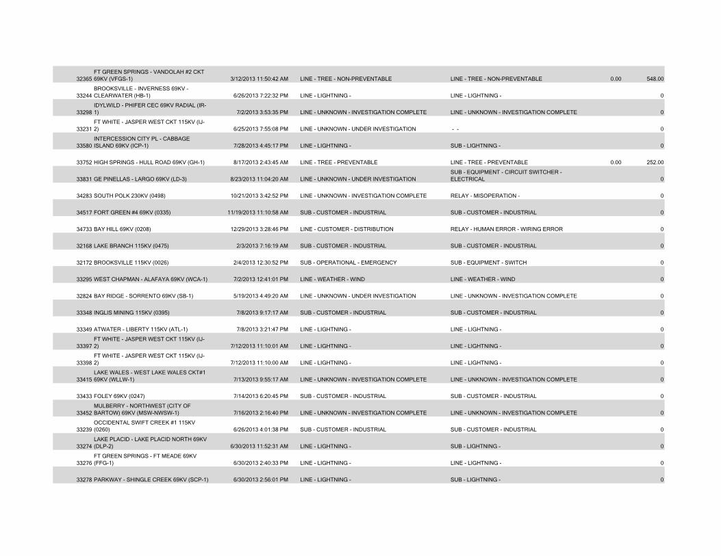
32365FT GREEN SPRINGS - VANDOLAH #2 CKT 69KV (VFGS-1) 3/12/2013 11:50:42 AM LINE - TREE - NON-PREVENTABLE LINE - TREE - NON-PREVENTABLE 0.00 548.00
33244BROOKSVILLE - INVERNESS 69KV - CLEARWATER (HB-1) 6/26/2013 7:22:32 PM LINE - LIGHTNING - LINE - LIGHTNING - 0
33298IDYLWILD - PHIFER CEC 69KV RADIAL (IR-1) 7/2/2013 3:53:35 PM LINE - UNKNOWN - INVESTIGATION COMPLETE LINE - UNKNOWN - INVESTIGATION COMPLETE 0
33231FT WHITE - JASPER WEST CKT 115KV (IJ-2) 6/25/2013 7:55:08 PM LINE - UNKNOWN - UNDER INVESTIGATION - - 0
33580INTERCESSION CITY PL - CABBAGE ISLAND 69KV (ICP-1) 7/28/2013 4:45:17 PM LINE - LIGHTNING - SUB - LIGHTNING - 0
33752 HIGH SPRINGS - HULL ROAD 69KV (GH-1) 8/17/2013 2:43:45 AM LINE - TREE - PREVENTABLE LINE - TREE - PREVENTABLE 0.00 252.00
33831 GE PINELLAS - LARGO 69KV (LD-3) 8/23/2013 11:04:20 AM LINE - UNKNOWN - UNDER INVESTIGATIONSUB - EQUIPMENT - CIRCUIT SWITCHER - ELECTRICAL 0
34283 SOUTH POLK 230KV (0498) 10/21/2013 3:42:52 PM LINE - UNKNOWN - INVESTIGATION COMPLETE RELAY - MISOPERATION - 0
34517 FORT GREEN #4 69KV (0335) 11/19/2013 11:10:58 AM SUB - CUSTOMER - INDUSTRIAL SUB - CUSTOMER - INDUSTRIAL 0
34733 BAY HILL 69KV (0208) 12/29/2013 3:28:46 PM LINE - CUSTOMER - DISTRIBUTION RELAY - HUMAN ERROR - WIRING ERROR 0
32168 LAKE BRANCH 115KV (0475) 2/3/2013 7:16:19 AM SUB - CUSTOMER - INDUSTRIAL SUB - CUSTOMER - INDUSTRIAL 0
32172 BROOKSVILLE 115KV (0026) 2/4/2013 12:30:52 PM SUB - OPERATIONAL - EMERGENCY SUB - EQUIPMENT - SWITCH 0
33295 WEST CHAPMAN - ALAFAYA 69KV (WCA-1) 7/2/2013 12:41:01 PM LINE - WEATHER - WIND LINE - WEATHER - WIND 0
32824 BAY RIDGE - SORRENTO 69KV (SB-1) 5/19/2013 4:49:20 AM LINE - UNKNOWN - UNDER INVESTIGATION LINE - UNKNOWN - INVESTIGATION COMPLETE 0
33348 INGLIS MINING 115KV (0395) 7/8/2013 9:17:17 AM SUB - CUSTOMER - INDUSTRIAL SUB - CUSTOMER - INDUSTRIAL 0
33349 ATWATER - LIBERTY 115KV (ATL-1) 7/8/2013 3:21:47 PM LINE - LIGHTNING - LINE - LIGHTNING - 0
33397FT WHITE - JASPER WEST CKT 115KV (IJ-2) 7/12/2013 11:10:01 AM LINE - LIGHTNING - LINE - LIGHTNING - 0
33398FT WHITE - JASPER WEST CKT 115KV (IJ-2) 7/12/2013 11:10:00 AM LINE - LIGHTNING - LINE - LIGHTNING - 0
33415LAKE WALES - WEST LAKE WALES CKT#1 69KV (WLLW-1) 7/13/2013 9:55:17 AM LINE - UNKNOWN - INVESTIGATION COMPLETE LINE - UNKNOWN - INVESTIGATION COMPLETE 0
33433 FOLEY 69KV (0247) 7/14/2013 6:20:45 PM SUB - CUSTOMER - INDUSTRIAL SUB - CUSTOMER - INDUSTRIAL 0
33452MULBERRY - NORTHWEST (CITY OF BARTOW) 69KV (MSW-NWSW-1) 7/16/2013 2:16:40 PM LINE - UNKNOWN - INVESTIGATION COMPLETE LINE - UNKNOWN - INVESTIGATION COMPLETE 0
33239OCCIDENTAL SWIFT CREEK #1 115KV (0260) 6/26/2013 4:01:38 PM SUB - CUSTOMER - INDUSTRIAL SUB - CUSTOMER - INDUSTRIAL 0
33274LAKE PLACID - LAKE PLACID NORTH 69KV (DLP-2) 6/30/2013 11:52:31 AM LINE - LIGHTNING - SUB - LIGHTNING - 0
33276FT GREEN SPRINGS - FT MEADE 69KV (FFG-1) 6/30/2013 2:40:33 PM LINE - LIGHTNING - LINE - LIGHTNING - 0
33278 PARKWAY - SHINGLE CREEK 69KV (SCP-1) 6/30/2013 2:56:01 PM LINE - LIGHTNING - SUB - LIGHTNING - 0
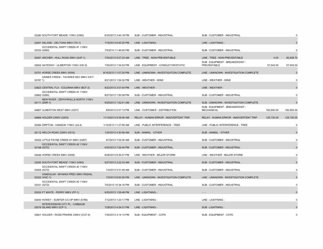
33280 SOUTH FORT MEADE 115KV (0360) 6/30/2013 3:40:18 PM SUB - CUSTOMER - INDUSTRIAL SUB - CUSTOMER - INDUSTRIAL 0
33491 DELAND - DELTONA 69KV (TD-1) 7/19/2013 6:40:20 PM LINE - LIGHTNING - LINE - LIGHTNING - 0
33333OCCIDENTAL SWIFT CREEK #1 115KV (0260) 7/5/2013 11:46:50 PM SUB - CUSTOMER - INDUSTRIAL SUB - CUSTOMER - INDUSTRIAL 0
33597 ARCHER - HULL ROAD 69KV (AUF-1) 7/30/2013 9:27:23 AM LINE - TREE - NON-PREVENTABLE LINE - TREE - NON-PREVENTABLE 0.00 82,838.70
33602 GATEWAY - ULMERTON 115KV (HD-5) 7/30/2013 7:34:53 PM LINE - EQUIPMENT - CONDUCTOR/STATICSUB - EQUIPMENT - BREAKER/DIST - PREVENTABLE 57,543.00 57,543.00
33751 HORSE CREEK 69KV (0006) 8/16/2013 11:07:20 PM LINE - UNKNOWN - INVESTIGATION COMPLETE LINE - UNKNOWN - INVESTIGATION COMPLETE 0
33797HAINES CREEK - TAVARES SEC 69KV (HCT-1) 8/21/2013 1:54:32 PM LINE - WEATHER - WIND LINE - WEATHER - WIND 0
33823 CENTRAL FLA - COLEMAN 69KV (BCF-2) 8/22/2013 3:07:44 PM LINE - WEATHER - LINE - WEATHER - 0
33862OCCIDENTAL SWIFT CREEK #1 115KV (0260) 8/27/2013 7:50:08 PM SUB - CUSTOMER - INDUSTRIAL SUB - CUSTOMER - INDUSTRIAL 0
34111NEW RIVER - ZEPHYRHILLS NORTH 115KV (ZNR-1) 9/25/2013 1:52:41 AM LINE - UNKNOWN - INVESTIGATION COMPLETE SUB - UNKNOWN - INVESTIGATION COMPLETE 0
34857 ULMERTON WEST 69KV (0337) 8/9/2013 5:07:13 PM LINE - CUSTOMER - DISTRIBUTIONSUB - EQUIPMENT - BREAKER/DIST - MECHANICAL 160,650.00 160,650.00
34866 HOLDER 230KV (0203) 11/14/2013 9:39:06 AM RELAY - HUMAN ERROR - INADVERTENT TRIP RELAY - HUMAN ERROR - INADVERTENT TRIP 125,730.00 125,730.00
32084 DRIFTON - HANSON 115KV (JQ-4) 1/10/2013 11:27:59 AM LINE - PUBLIC INTERFERENCE - TREE LINE - PUBLIC INTERFERENCE - TREE 0
32112 WELCH ROAD 230KV (0312) 1/20/2013 4:30:56 AM SUB - ANIMAL - OTHER SUB - ANIMAL - OTHER 0
33022 LITTLE PAYNE CREEK #1 69KV (0287) 6/7/2013 7:02:00 AM SUB - CUSTOMER - INDUSTRIAL SUB - CUSTOMER - INDUSTRIAL 0
33168OCCIDENTAL SWIFT CREEK #2 115KV (0272) 6/20/2013 7:26:40 PM SUB - CUSTOMER - INDUSTRIAL SUB - CUSTOMER - INDUSTRIAL 0
33246 HORSE CREEK 69KV (0006) 6/26/2013 8:35:07 PM LINE - WEATHER - MAJOR STORM LINE - WEATHER - MAJOR STORM 0
33250 SOUTH FORT MEADE 115KV (0360) 6/27/2013 2:22:33 AM SUB - CUSTOMER - INDUSTRIAL SUB - CUSTOMER - INDUSTRIAL 0
33305OCCIDENTAL SWIFT CREEK #2 115KV (0272) 7/3/2013 5:31:49 AM SUB - CUSTOMER - INDUSTRIAL SUB - CUSTOMER - INDUSTRIAL 0
33322VANDOLAH - MYAKKA PREC 69KV RADIAL (VHC-1) 7/3/2013 8:50:26 PM LINE - UNKNOWN - INVESTIGATION COMPLETE LINE - UNKNOWN - INVESTIGATION COMPLETE 0
33331OCCIDENTAL SWIFT CREEK #2 115KV (0272) 7/5/2013 10:34:16 PM SUB - CUSTOMER - INDUSTRIAL SUB - CUSTOMER - INDUSTRIAL 0
33220 FT WHITE - PERRY 69KV (FP-1) 6/25/2013 1:59:48 PM LINE - LIGHTNING - - - 0
33400 HOWEY - SUMTER CO-OP 69KV (6786) 7/12/2013 1:23:17 PM LINE - LIGHTNING - LINE - LIGHTNING - 0
33579INTERCESSION CITY PL - CABBAGE ISLAND 69KV (ICP-1) 7/28/2013 4:34:31 PM LINE - LIGHTNING - SUB - LIGHTNING - 0
33601 HOLDER - ROSS PRAIRIE 230KV (CCF-6) 7/30/2013 3:14:13 PM SUB - EQUIPMENT - CCPD SUB - EQUIPMENT - CCPD 0
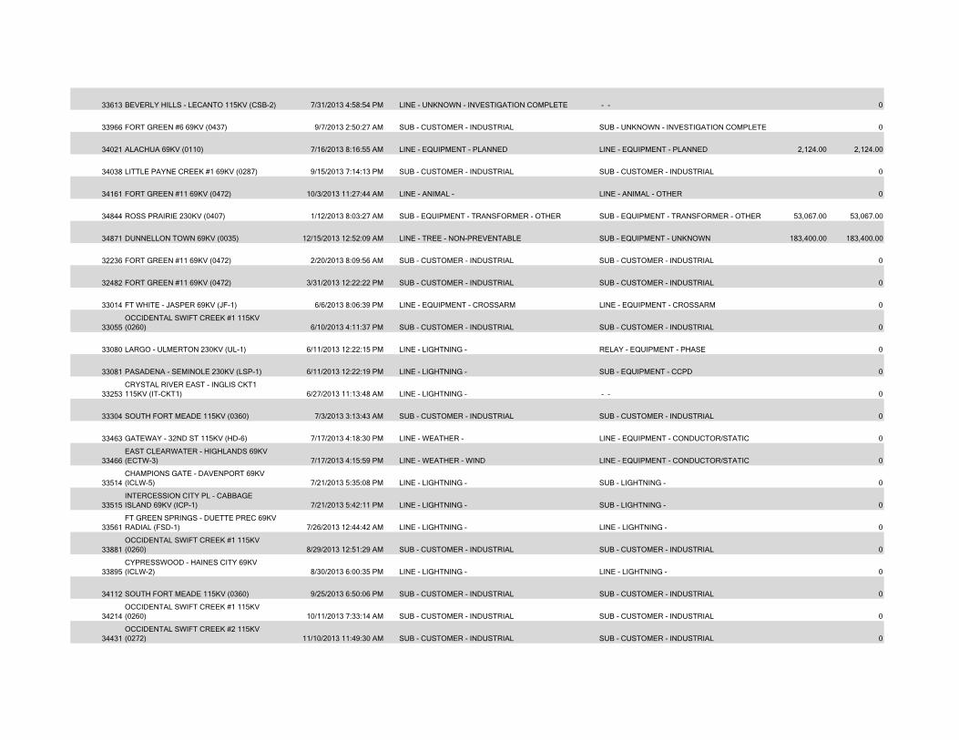
33613 BEVERLY HILLS - LECANTO 115KV (CSB-2) 7/31/2013 4:58:54 PM LINE - UNKNOWN - INVESTIGATION COMPLETE - - 0
33966 FORT GREEN #6 69KV (0437) 9/7/2013 2:50:27 AM SUB - CUSTOMER - INDUSTRIAL SUB - UNKNOWN - INVESTIGATION COMPLETE 0
34021 ALACHUA 69KV (0110) 7/16/2013 8:16:55 AM LINE - EQUIPMENT - PLANNED LINE - EQUIPMENT - PLANNED 2,124.00 2,124.00
34038 LITTLE PAYNE CREEK #1 69KV (0287) 9/15/2013 7:14:13 PM SUB - CUSTOMER - INDUSTRIAL SUB - CUSTOMER - INDUSTRIAL 0
34161 FORT GREEN #11 69KV (0472) 10/3/2013 11:27:44 AM LINE - ANIMAL - LINE - ANIMAL - OTHER 0
34844 ROSS PRAIRIE 230KV (0407) 1/12/2013 8:03:27 AM SUB - EQUIPMENT - TRANSFORMER - OTHER SUB - EQUIPMENT - TRANSFORMER - OTHER 53,067.00 53,067.00
34871 DUNNELLON TOWN 69KV (0035) 12/15/2013 12:52:09 AM LINE - TREE - NON-PREVENTABLE SUB - EQUIPMENT - UNKNOWN 183,400.00 183,400.00
32236 FORT GREEN #11 69KV (0472) 2/20/2013 8:09:56 AM SUB - CUSTOMER - INDUSTRIAL SUB - CUSTOMER - INDUSTRIAL 0
32482 FORT GREEN #11 69KV (0472) 3/31/2013 12:22:22 PM SUB - CUSTOMER - INDUSTRIAL SUB - CUSTOMER - INDUSTRIAL 0
33014 FT WHITE - JASPER 69KV (JF-1) 6/6/2013 8:06:39 PM LINE - EQUIPMENT - CROSSARM LINE - EQUIPMENT - CROSSARM 0
33055OCCIDENTAL SWIFT CREEK #1 115KV (0260) 6/10/2013 4:11:37 PM SUB - CUSTOMER - INDUSTRIAL SUB - CUSTOMER - INDUSTRIAL 0
33080 LARGO - ULMERTON 230KV (UL-1) 6/11/2013 12:22:15 PM LINE - LIGHTNING - RELAY - EQUIPMENT - PHASE 0
33081 PASADENA - SEMINOLE 230KV (LSP-1) 6/11/2013 12:22:19 PM LINE - LIGHTNING - SUB - EQUIPMENT - CCPD 0
33253CRYSTAL RIVER EAST - INGLIS CKT1 115KV (IT-CKT1) 6/27/2013 11:13:48 AM LINE - LIGHTNING - - - 0
33304 SOUTH FORT MEADE 115KV (0360) 7/3/2013 3:13:43 AM SUB - CUSTOMER - INDUSTRIAL SUB - CUSTOMER - INDUSTRIAL 0
33463 GATEWAY - 32ND ST 115KV (HD-6) 7/17/2013 4:18:30 PM LINE - WEATHER - LINE - EQUIPMENT - CONDUCTOR/STATIC 0
33466EAST CLEARWATER - HIGHLANDS 69KV (ECTW-3) 7/17/2013 4:15:59 PM LINE - WEATHER - WIND LINE - EQUIPMENT - CONDUCTOR/STATIC 0
33514CHAMPIONS GATE - DAVENPORT 69KV (ICLW-5) 7/21/2013 5:35:08 PM LINE - LIGHTNING - SUB - LIGHTNING - 0
33515INTERCESSION CITY PL - CABBAGE ISLAND 69KV (ICP-1) 7/21/2013 5:42:11 PM LINE - LIGHTNING - SUB - LIGHTNING - 0
33561FT GREEN SPRINGS - DUETTE PREC 69KV RADIAL (FSD-1) 7/26/2013 12:44:42 AM LINE - LIGHTNING - LINE - LIGHTNING - 0
33881OCCIDENTAL SWIFT CREEK #1 115KV (0260) 8/29/2013 12:51:29 AM SUB - CUSTOMER - INDUSTRIAL SUB - CUSTOMER - INDUSTRIAL 0
33895CYPRESSWOOD - HAINES CITY 69KV (ICLW-2) 8/30/2013 6:00:35 PM LINE - LIGHTNING - LINE - LIGHTNING - 0
34112 SOUTH FORT MEADE 115KV (0360) 9/25/2013 6:50:06 PM SUB - CUSTOMER - INDUSTRIAL SUB - CUSTOMER - INDUSTRIAL 0
34214OCCIDENTAL SWIFT CREEK #1 115KV (0260) 10/11/2013 7:33:14 AM SUB - CUSTOMER - INDUSTRIAL SUB - CUSTOMER - INDUSTRIAL 0
34431OCCIDENTAL SWIFT CREEK #2 115KV (0272) 11/10/2013 11:49:30 AM SUB - CUSTOMER - INDUSTRIAL SUB - CUSTOMER - INDUSTRIAL 0
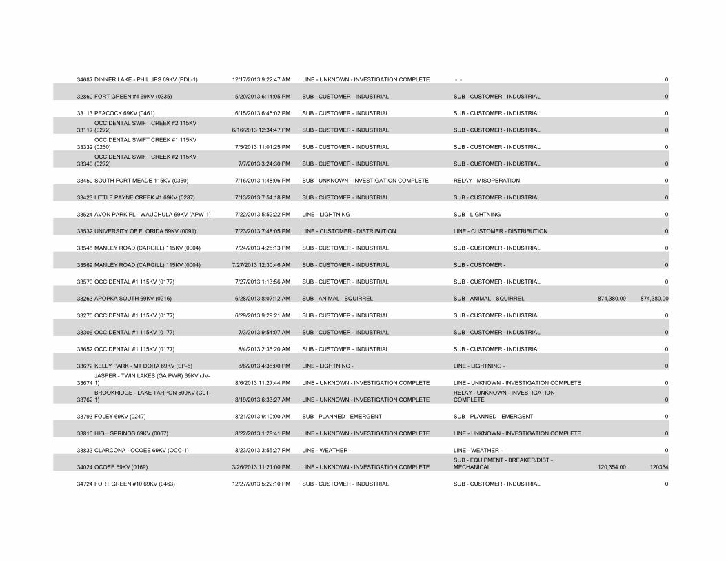
34687 DINNER LAKE - PHILLIPS 69KV (PDL-1) 12/17/2013 9:22:47 AM LINE - UNKNOWN - INVESTIGATION COMPLETE - - 0
32860 FORT GREEN #4 69KV (0335) 5/20/2013 6:14:05 PM SUB - CUSTOMER - INDUSTRIAL SUB - CUSTOMER - INDUSTRIAL 0
33113 PEACOCK 69KV (0461) 6/15/2013 6:45:02 PM SUB - CUSTOMER - INDUSTRIAL SUB - CUSTOMER - INDUSTRIAL 0
33117OCCIDENTAL SWIFT CREEK #2 115KV (0272) 6/16/2013 12:34:47 PM SUB - CUSTOMER - INDUSTRIAL SUB - CUSTOMER - INDUSTRIAL 0
33332OCCIDENTAL SWIFT CREEK #1 115KV (0260) 7/5/2013 11:01:25 PM SUB - CUSTOMER - INDUSTRIAL SUB - CUSTOMER - INDUSTRIAL 0
33340OCCIDENTAL SWIFT CREEK #2 115KV (0272) 7/7/2013 3:24:30 PM SUB - CUSTOMER - INDUSTRIAL SUB - CUSTOMER - INDUSTRIAL 0
33450 SOUTH FORT MEADE 115KV (0360) 7/16/2013 1:48:06 PM SUB - UNKNOWN - INVESTIGATION COMPLETE RELAY - MISOPERATION - 0
33423 LITTLE PAYNE CREEK #1 69KV (0287) 7/13/2013 7:54:18 PM SUB - CUSTOMER - INDUSTRIAL SUB - CUSTOMER - INDUSTRIAL 0
33524 AVON PARK PL - WAUCHULA 69KV (APW-1) 7/22/2013 5:52:22 PM LINE - LIGHTNING - SUB - LIGHTNING - 0
33532 UNIVERSITY OF FLORIDA 69KV (0091) 7/23/2013 7:48:05 PM LINE - CUSTOMER - DISTRIBUTION LINE - CUSTOMER - DISTRIBUTION 0
33545 MANLEY ROAD (CARGILL) 115KV (0004) 7/24/2013 4:25:13 PM SUB - CUSTOMER - INDUSTRIAL SUB - CUSTOMER - INDUSTRIAL 0
33569 MANLEY ROAD (CARGILL) 115KV (0004) 7/27/2013 12:30:46 AM SUB - CUSTOMER - INDUSTRIAL SUB - CUSTOMER - 0
33570 OCCIDENTAL #1 115KV (0177) 7/27/2013 1:13:56 AM SUB - CUSTOMER - INDUSTRIAL SUB - CUSTOMER - INDUSTRIAL 0
33263 APOPKA SOUTH 69KV (0216) 6/28/2013 8:07:12 AM SUB - ANIMAL - SQUIRREL SUB - ANIMAL - SQUIRREL 874,380.00 874,380.00
33270 OCCIDENTAL #1 115KV (0177) 6/29/2013 9:29:21 AM SUB - CUSTOMER - INDUSTRIAL SUB - CUSTOMER - INDUSTRIAL 0
33306 OCCIDENTAL #1 115KV (0177) 7/3/2013 9:54:07 AM SUB - CUSTOMER - INDUSTRIAL SUB - CUSTOMER - INDUSTRIAL 0
33652 OCCIDENTAL #1 115KV (0177) 8/4/2013 2:36:20 AM SUB - CUSTOMER - INDUSTRIAL SUB - CUSTOMER - INDUSTRIAL 0
33672 KELLY PARK - MT DORA 69KV (EP-5) 8/6/2013 4:35:00 PM LINE - LIGHTNING - LINE - LIGHTNING - 0
33674JASPER - TWIN LAKES (GA PWR) 69KV (JV-1) 8/6/2013 11:27:44 PM LINE - UNKNOWN - INVESTIGATION COMPLETE LINE - UNKNOWN - INVESTIGATION COMPLETE 0
33762BROOKRIDGE - LAKE TARPON 500KV (CLT-1) 8/19/2013 6:33:27 AM LINE - UNKNOWN - INVESTIGATION COMPLETE
RELAY - UNKNOWN - INVESTIGATION COMPLETE 0
33793 FOLEY 69KV (0247) 8/21/2013 9:10:00 AM SUB - PLANNED - EMERGENT SUB - PLANNED - EMERGENT 0
33816 HIGH SPRINGS 69KV (0067) 8/22/2013 1:28:41 PM LINE - UNKNOWN - INVESTIGATION COMPLETE LINE - UNKNOWN - INVESTIGATION COMPLETE 0
33833 CLARCONA - OCOEE 69KV (OCC-1) 8/23/2013 3:55:27 PM LINE - WEATHER - LINE - WEATHER - 0
34024 OCOEE 69KV (0169) 3/26/2013 11:21:00 PM LINE - UNKNOWN - INVESTIGATION COMPLETESUB - EQUIPMENT - BREAKER/DIST - MECHANICAL 120,354.00 120354
34724 FORT GREEN #10 69KV (0463) 12/27/2013 5:22:10 PM SUB - CUSTOMER - INDUSTRIAL SUB - CUSTOMER - INDUSTRIAL 0
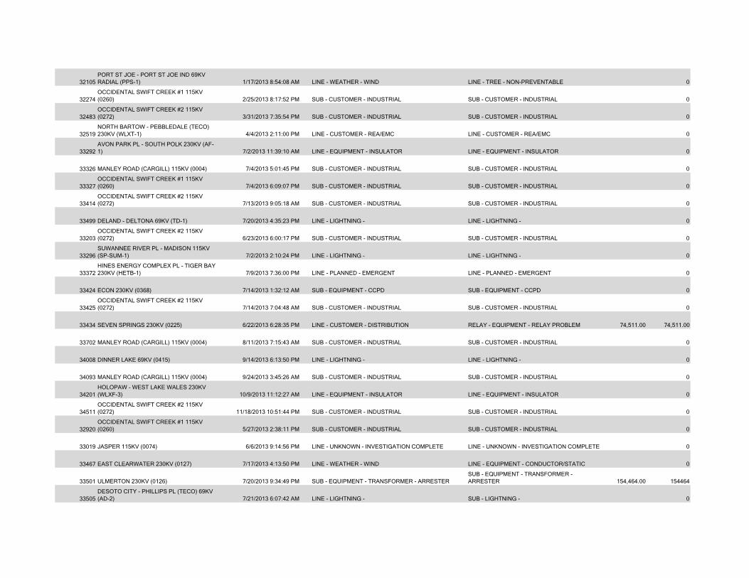
32105PORT ST JOE - PORT ST JOE IND 69KV RADIAL (PPS-1) 1/17/2013 8:54:08 AM LINE - WEATHER - WIND LINE - TREE - NON-PREVENTABLE 0
32274OCCIDENTAL SWIFT CREEK #1 115KV (0260) 2/25/2013 8:17:52 PM SUB - CUSTOMER - INDUSTRIAL SUB - CUSTOMER - INDUSTRIAL 0
32483OCCIDENTAL SWIFT CREEK #2 115KV (0272) 3/31/2013 7:35:54 PM SUB - CUSTOMER - INDUSTRIAL SUB - CUSTOMER - INDUSTRIAL 0
32519NORTH BARTOW - PEBBLEDALE (TECO) 230KV (WLXT-1) 4/4/2013 2:11:00 PM LINE - CUSTOMER - REA/EMC LINE - CUSTOMER - REA/EMC 0
33292AVON PARK PL - SOUTH POLK 230KV (AF-1) 7/2/2013 11:39:10 AM LINE - EQUIPMENT - INSULATOR LINE - EQUIPMENT - INSULATOR 0
33326 MANLEY ROAD (CARGILL) 115KV (0004) 7/4/2013 5:01:45 PM SUB - CUSTOMER - INDUSTRIAL SUB - CUSTOMER - INDUSTRIAL 0
33327OCCIDENTAL SWIFT CREEK #1 115KV (0260) 7/4/2013 6:09:07 PM SUB - CUSTOMER - INDUSTRIAL SUB - CUSTOMER - INDUSTRIAL 0
33414OCCIDENTAL SWIFT CREEK #2 115KV (0272) 7/13/2013 9:05:18 AM SUB - CUSTOMER - INDUSTRIAL SUB - CUSTOMER - INDUSTRIAL 0
33499 DELAND - DELTONA 69KV (TD-1) 7/20/2013 4:35:23 PM LINE - LIGHTNING - LINE - LIGHTNING - 0
33203OCCIDENTAL SWIFT CREEK #2 115KV (0272) 6/23/2013 6:00:17 PM SUB - CUSTOMER - INDUSTRIAL SUB - CUSTOMER - INDUSTRIAL 0
33296SUWANNEE RIVER PL - MADISON 115KV (SP-SUM-1) 7/2/2013 2:10:24 PM LINE - LIGHTNING - LINE - LIGHTNING - 0
33372HINES ENERGY COMPLEX PL - TIGER BAY 230KV (HETB-1) 7/9/2013 7:36:00 PM LINE - PLANNED - EMERGENT LINE - PLANNED - EMERGENT 0
33424 ECON 230KV (0368) 7/14/2013 1:32:12 AM SUB - EQUIPMENT - CCPD SUB - EQUIPMENT - CCPD 0
33425OCCIDENTAL SWIFT CREEK #2 115KV (0272) 7/14/2013 7:04:48 AM SUB - CUSTOMER - INDUSTRIAL SUB - CUSTOMER - INDUSTRIAL 0
33434 SEVEN SPRINGS 230KV (0225) 6/22/2013 6:28:35 PM LINE - CUSTOMER - DISTRIBUTION RELAY - EQUIPMENT - RELAY PROBLEM 74,511.00 74,511.00
33702 MANLEY ROAD (CARGILL) 115KV (0004) 8/11/2013 7:15:43 AM SUB - CUSTOMER - INDUSTRIAL SUB - CUSTOMER - INDUSTRIAL 0
34008 DINNER LAKE 69KV (0415) 9/14/2013 6:13:50 PM LINE - LIGHTNING - LINE - LIGHTNING - 0
34093 MANLEY ROAD (CARGILL) 115KV (0004) 9/24/2013 3:45:26 AM SUB - CUSTOMER - INDUSTRIAL SUB - CUSTOMER - INDUSTRIAL 0
34201HOLOPAW - WEST LAKE WALES 230KV (WLXF-3) 10/9/2013 11:12:27 AM LINE - EQUIPMENT - INSULATOR LINE - EQUIPMENT - INSULATOR 0
34511OCCIDENTAL SWIFT CREEK #2 115KV (0272) 11/18/2013 10:51:44 PM SUB - CUSTOMER - INDUSTRIAL SUB - CUSTOMER - INDUSTRIAL 0
32920OCCIDENTAL SWIFT CREEK #1 115KV (0260) 5/27/2013 2:38:11 PM SUB - CUSTOMER - INDUSTRIAL SUB - CUSTOMER - INDUSTRIAL 0
33019 JASPER 115KV (0074) 6/6/2013 9:14:56 PM LINE - UNKNOWN - INVESTIGATION COMPLETE LINE - UNKNOWN - INVESTIGATION COMPLETE 0
33467 EAST CLEARWATER 230KV (0127) 7/17/2013 4:13:50 PM LINE - WEATHER - WIND LINE - EQUIPMENT - CONDUCTOR/STATIC 0
33501 ULMERTON 230KV (0126) 7/20/2013 9:34:49 PM SUB - EQUIPMENT - TRANSFORMER - ARRESTERSUB - EQUIPMENT - TRANSFORMER - ARRESTER 154,464.00 154464
33505DESOTO CITY - PHILLIPS PL (TECO) 69KV (AD-2) 7/21/2013 6:07:42 AM LINE - LIGHTNING - SUB - LIGHTNING - 0
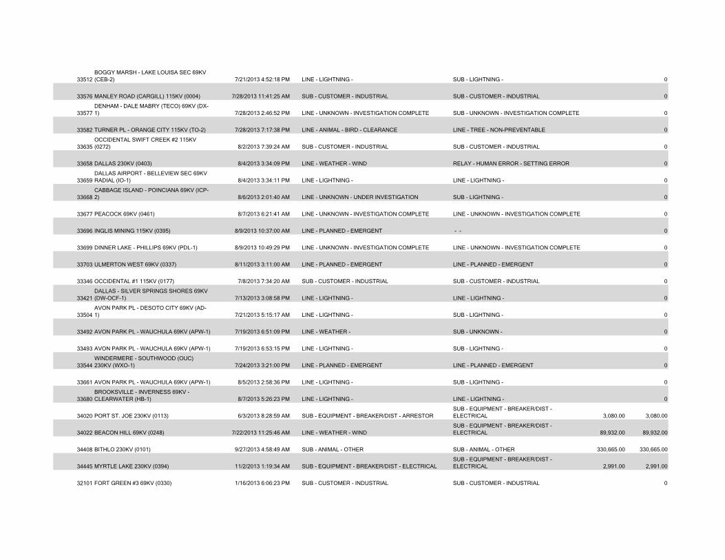
33512BOGGY MARSH - LAKE LOUISA SEC 69KV (CEB-2) 7/21/2013 4:52:18 PM LINE - LIGHTNING - SUB - LIGHTNING - 0
33576 MANLEY ROAD (CARGILL) 115KV (0004) 7/28/2013 11:41:25 AM SUB - CUSTOMER - INDUSTRIAL SUB - CUSTOMER - INDUSTRIAL 0
33577DENHAM - DALE MABRY (TECO) 69KV (DX-1) 7/28/2013 2:46:52 PM LINE - UNKNOWN - INVESTIGATION COMPLETE SUB - UNKNOWN - INVESTIGATION COMPLETE 0
33582 TURNER PL - ORANGE CITY 115KV (TO-2) 7/28/2013 7:17:38 PM LINE - ANIMAL - BIRD - CLEARANCE LINE - TREE - NON-PREVENTABLE 0
33635OCCIDENTAL SWIFT CREEK #2 115KV (0272) 8/2/2013 7:39:24 AM SUB - CUSTOMER - INDUSTRIAL SUB - CUSTOMER - INDUSTRIAL 0
33658 DALLAS 230KV (0403) 8/4/2013 3:34:09 PM LINE - WEATHER - WIND RELAY - HUMAN ERROR - SETTING ERROR 0
33659DALLAS AIRPORT - BELLEVIEW SEC 69KV RADIAL (IO-1) 8/4/2013 3:34:11 PM LINE - LIGHTNING - LINE - LIGHTNING - 0
33668CABBAGE ISLAND - POINCIANA 69KV (ICP-2) 8/6/2013 2:01:40 AM LINE - UNKNOWN - UNDER INVESTIGATION SUB - LIGHTNING - 0
33677 PEACOCK 69KV (0461) 8/7/2013 6:21:41 AM LINE - UNKNOWN - INVESTIGATION COMPLETE LINE - UNKNOWN - INVESTIGATION COMPLETE 0
33696 INGLIS MINING 115KV (0395) 8/9/2013 10:37:00 AM LINE - PLANNED - EMERGENT - - 0
33699 DINNER LAKE - PHILLIPS 69KV (PDL-1) 8/9/2013 10:49:29 PM LINE - UNKNOWN - INVESTIGATION COMPLETE LINE - UNKNOWN - INVESTIGATION COMPLETE 0
33703 ULMERTON WEST 69KV (0337) 8/11/2013 3:11:00 AM LINE - PLANNED - EMERGENT LINE - PLANNED - EMERGENT 0
33346 OCCIDENTAL #1 115KV (0177) 7/8/2013 7:34:20 AM SUB - CUSTOMER - INDUSTRIAL SUB - CUSTOMER - INDUSTRIAL 0
33421DALLAS - SILVER SPRINGS SHORES 69KV (DW-OCF-1) 7/13/2013 3:08:58 PM LINE - LIGHTNING - LINE - LIGHTNING - 0
33504AVON PARK PL - DESOTO CITY 69KV (AD-1) 7/21/2013 5:15:17 AM LINE - LIGHTNING - SUB - LIGHTNING - 0
33492 AVON PARK PL - WAUCHULA 69KV (APW-1) 7/19/2013 6:51:09 PM LINE - WEATHER - SUB - UNKNOWN - 0
33493 AVON PARK PL - WAUCHULA 69KV (APW-1) 7/19/2013 6:53:15 PM LINE - LIGHTNING - SUB - LIGHTNING - 0
33544WINDERMERE - SOUTHWOOD (OUC) 230KV (WXO-1) 7/24/2013 3:21:00 PM LINE - PLANNED - EMERGENT LINE - PLANNED - EMERGENT 0
33661 AVON PARK PL - WAUCHULA 69KV (APW-1) 8/5/2013 2:58:36 PM LINE - LIGHTNING - SUB - LIGHTNING - 0
33680BROOKSVILLE - INVERNESS 69KV - CLEARWATER (HB-1) 8/7/2013 5:26:23 PM LINE - LIGHTNING - LINE - LIGHTNING - 0
34020 PORT ST. JOE 230KV (0113) 6/3/2013 8:28:59 AM SUB - EQUIPMENT - BREAKER/DIST - ARRESTORSUB - EQUIPMENT - BREAKER/DIST - ELECTRICAL 3,080.00 3,080.00
34022 BEACON HILL 69KV (0248) 7/22/2013 11:25:46 AM LINE - WEATHER - WINDSUB - EQUIPMENT - BREAKER/DIST - ELECTRICAL 89,932.00 89,932.00
34408 BITHLO 230KV (0101) 9/27/2013 4:58:49 AM SUB - ANIMAL - OTHER SUB - ANIMAL - OTHER 330,665.00 330,665.00
34445 MYRTLE LAKE 230KV (0394) 11/2/2013 1:19:34 AM SUB - EQUIPMENT - BREAKER/DIST - ELECTRICALSUB - EQUIPMENT - BREAKER/DIST - ELECTRICAL 2,991.00 2,991.00
32101 FORT GREEN #3 69KV (0330) 1/16/2013 6:06:23 PM SUB - CUSTOMER - INDUSTRIAL SUB - CUSTOMER - INDUSTRIAL 0
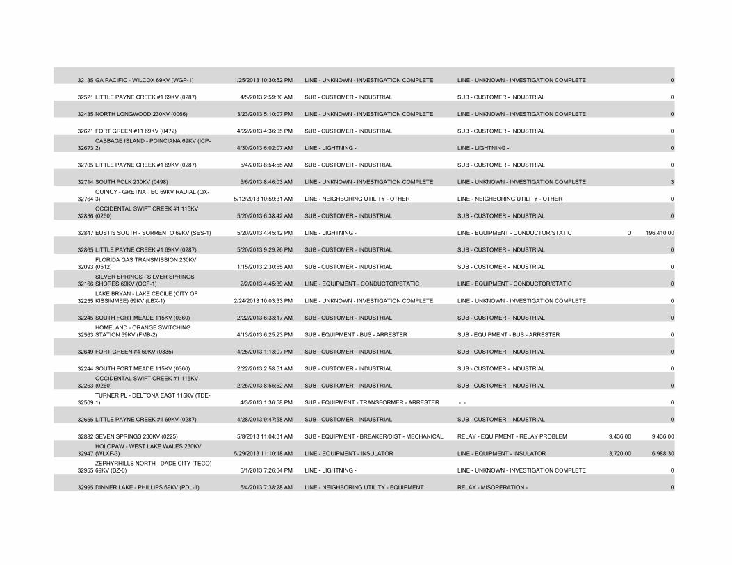
32135 GA PACIFIC - WILCOX 69KV (WGP-1) 1/25/2013 10:30:52 PM LINE - UNKNOWN - INVESTIGATION COMPLETE LINE - UNKNOWN - INVESTIGATION COMPLETE 0
32521 LITTLE PAYNE CREEK #1 69KV (0287) 4/5/2013 2:59:30 AM SUB - CUSTOMER - INDUSTRIAL SUB - CUSTOMER - INDUSTRIAL 0
32435 NORTH LONGWOOD 230KV (0066) 3/23/2013 5:10:07 PM LINE - UNKNOWN - INVESTIGATION COMPLETE LINE - UNKNOWN - INVESTIGATION COMPLETE 0
32621 FORT GREEN #11 69KV (0472) 4/22/2013 4:36:05 PM SUB - CUSTOMER - INDUSTRIAL SUB - CUSTOMER - INDUSTRIAL 0
32673CABBAGE ISLAND - POINCIANA 69KV (ICP-2) 4/30/2013 6:02:07 AM LINE - LIGHTNING - LINE - LIGHTNING - 0
32705 LITTLE PAYNE CREEK #1 69KV (0287) 5/4/2013 8:54:55 AM SUB - CUSTOMER - INDUSTRIAL SUB - CUSTOMER - INDUSTRIAL 0
32714 SOUTH POLK 230KV (0498) 5/6/2013 8:46:03 AM LINE - UNKNOWN - INVESTIGATION COMPLETE LINE - UNKNOWN - INVESTIGATION COMPLETE 3
32764QUINCY - GRETNA TEC 69KV RADIAL (QX-3) 5/12/2013 10:59:31 AM LINE - NEIGHBORING UTILITY - OTHER LINE - NEIGHBORING UTILITY - OTHER 0
32836OCCIDENTAL SWIFT CREEK #1 115KV (0260) 5/20/2013 6:38:42 AM SUB - CUSTOMER - INDUSTRIAL SUB - CUSTOMER - INDUSTRIAL 0
32847 EUSTIS SOUTH - SORRENTO 69KV (SES-1) 5/20/2013 4:45:12 PM LINE - LIGHTNING - LINE - EQUIPMENT - CONDUCTOR/STATIC 0 196,410.00
32865 LITTLE PAYNE CREEK #1 69KV (0287) 5/20/2013 9:29:26 PM SUB - CUSTOMER - INDUSTRIAL SUB - CUSTOMER - INDUSTRIAL 0
32093FLORIDA GAS TRANSMISSION 230KV (0512) 1/15/2013 2:30:55 AM SUB - CUSTOMER - INDUSTRIAL SUB - CUSTOMER - INDUSTRIAL 0
32166SILVER SPRINGS - SILVER SPRINGS SHORES 69KV (OCF-1) 2/2/2013 4:45:39 AM LINE - EQUIPMENT - CONDUCTOR/STATIC LINE - EQUIPMENT - CONDUCTOR/STATIC 0
32255LAKE BRYAN - LAKE CECILE (CITY OF KISSIMMEE) 69KV (LBX-1) 2/24/2013 10:03:33 PM LINE - UNKNOWN - INVESTIGATION COMPLETE LINE - UNKNOWN - INVESTIGATION COMPLETE 0
32245 SOUTH FORT MEADE 115KV (0360) 2/22/2013 6:33:17 AM SUB - CUSTOMER - INDUSTRIAL SUB - CUSTOMER - INDUSTRIAL 0
32563HOMELAND - ORANGE SWITCHING STATION 69KV (FMB-2) 4/13/2013 6:25:23 PM SUB - EQUIPMENT - BUS - ARRESTER SUB - EQUIPMENT - BUS - ARRESTER 0
32649 FORT GREEN #4 69KV (0335) 4/25/2013 1:13:07 PM SUB - CUSTOMER - INDUSTRIAL SUB - CUSTOMER - INDUSTRIAL 0
32244 SOUTH FORT MEADE 115KV (0360) 2/22/2013 2:58:51 AM SUB - CUSTOMER - INDUSTRIAL SUB - CUSTOMER - INDUSTRIAL 0
32263OCCIDENTAL SWIFT CREEK #1 115KV (0260) 2/25/2013 8:55:52 AM SUB - CUSTOMER - INDUSTRIAL SUB - CUSTOMER - INDUSTRIAL 0
32509TURNER PL - DELTONA EAST 115KV (TDE-1) 4/3/2013 1:36:58 PM SUB - EQUIPMENT - TRANSFORMER - ARRESTER - - 0
32655 LITTLE PAYNE CREEK #1 69KV (0287) 4/28/2013 9:47:58 AM SUB - CUSTOMER - INDUSTRIAL SUB - CUSTOMER - INDUSTRIAL 0
32882 SEVEN SPRINGS 230KV (0225) 5/8/2013 11:04:31 AM SUB - EQUIPMENT - BREAKER/DIST - MECHANICAL RELAY - EQUIPMENT - RELAY PROBLEM 9,436.00 9,436.00
32947HOLOPAW - WEST LAKE WALES 230KV (WLXF-3) 5/29/2013 11:10:18 AM LINE - EQUIPMENT - INSULATOR LINE - EQUIPMENT - INSULATOR 3,720.00 6,988.30
32955ZEPHYRHILLS NORTH - DADE CITY (TECO) 69KV (BZ-6) 6/1/2013 7:26:04 PM LINE - LIGHTNING - LINE - UNKNOWN - INVESTIGATION COMPLETE 0
32995 DINNER LAKE - PHILLIPS 69KV (PDL-1) 6/4/2013 7:38:28 AM LINE - NEIGHBORING UTILITY - EQUIPMENT RELAY - MISOPERATION - 0
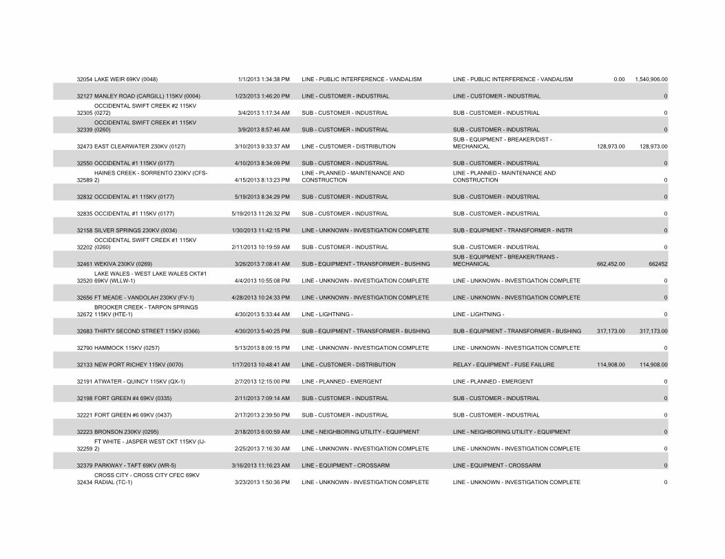
32054 LAKE WEIR 69KV (0048) 1/1/2013 1:34:38 PM LINE - PUBLIC INTERFERENCE - VANDALISM LINE - PUBLIC INTERFERENCE - VANDALISM 0.00 1,540,906.00
32127 MANLEY ROAD (CARGILL) 115KV (0004) 1/23/2013 1:46:20 PM LINE - CUSTOMER - INDUSTRIAL LINE - CUSTOMER - INDUSTRIAL 0
32305OCCIDENTAL SWIFT CREEK #2 115KV (0272) 3/4/2013 1:17:34 AM SUB - CUSTOMER - INDUSTRIAL SUB - CUSTOMER - INDUSTRIAL 0
32339OCCIDENTAL SWIFT CREEK #1 115KV (0260) 3/9/2013 8:57:46 AM SUB - CUSTOMER - INDUSTRIAL SUB - CUSTOMER - INDUSTRIAL 0
32473 EAST CLEARWATER 230KV (0127) 3/10/2013 9:33:37 AM LINE - CUSTOMER - DISTRIBUTIONSUB - EQUIPMENT - BREAKER/DIST - MECHANICAL 128,973.00 128,973.00
32550 OCCIDENTAL #1 115KV (0177) 4/10/2013 8:34:09 PM SUB - CUSTOMER - INDUSTRIAL SUB - CUSTOMER - INDUSTRIAL 0
32589HAINES CREEK - SORRENTO 230KV (CFS-2) 4/15/2013 8:13:23 PM
LINE - PLANNED - MAINTENANCE AND CONSTRUCTION
LINE - PLANNED - MAINTENANCE AND CONSTRUCTION 0
32832 OCCIDENTAL #1 115KV (0177) 5/19/2013 8:34:29 PM SUB - CUSTOMER - INDUSTRIAL SUB - CUSTOMER - INDUSTRIAL 0
32835 OCCIDENTAL #1 115KV (0177) 5/19/2013 11:26:32 PM SUB - CUSTOMER - INDUSTRIAL SUB - CUSTOMER - INDUSTRIAL 0
32158 SILVER SPRINGS 230KV (0034) 1/30/2013 11:42:15 PM LINE - UNKNOWN - INVESTIGATION COMPLETE SUB - EQUIPMENT - TRANSFORMER - INSTR 0
32202OCCIDENTAL SWIFT CREEK #1 115KV (0260) 2/11/2013 10:19:59 AM SUB - CUSTOMER - INDUSTRIAL SUB - CUSTOMER - INDUSTRIAL 0
32461 WEKIVA 230KV (0269) 3/26/2013 7:08:41 AM SUB - EQUIPMENT - TRANSFORMER - BUSHINGSUB - EQUIPMENT - BREAKER/TRANS - MECHANICAL 662,452.00 662452
32520LAKE WALES - WEST LAKE WALES CKT#1 69KV (WLLW-1) 4/4/2013 10:55:08 PM LINE - UNKNOWN - INVESTIGATION COMPLETE LINE - UNKNOWN - INVESTIGATION COMPLETE 0
32656 FT MEADE - VANDOLAH 230KV (FV-1) 4/28/2013 10:24:33 PM LINE - UNKNOWN - INVESTIGATION COMPLETE LINE - UNKNOWN - INVESTIGATION COMPLETE 0
32672BROOKER CREEK - TARPON SPRINGS 115KV (HTE-1) 4/30/2013 5:33:44 AM LINE - LIGHTNING - LINE - LIGHTNING - 0
32683 THIRTY SECOND STREET 115KV (0366) 4/30/2013 5:40:25 PM SUB - EQUIPMENT - TRANSFORMER - BUSHING SUB - EQUIPMENT - TRANSFORMER - BUSHING 317,173.00 317,173.00
32790 HAMMOCK 115KV (0257) 5/13/2013 8:09:15 PM LINE - UNKNOWN - INVESTIGATION COMPLETE LINE - UNKNOWN - INVESTIGATION COMPLETE 0
32133 NEW PORT RICHEY 115KV (0070) 1/17/2013 10:48:41 AM LINE - CUSTOMER - DISTRIBUTION RELAY - EQUIPMENT - FUSE FAILURE 114,908.00 114,908.00
32191 ATWATER - QUINCY 115KV (QX-1) 2/7/2013 12:15:00 PM LINE - PLANNED - EMERGENT LINE - PLANNED - EMERGENT 0
32198 FORT GREEN #4 69KV (0335) 2/11/2013 7:09:14 AM SUB - CUSTOMER - INDUSTRIAL SUB - CUSTOMER - INDUSTRIAL 0
32221 FORT GREEN #6 69KV (0437) 2/17/2013 2:39:50 PM SUB - CUSTOMER - INDUSTRIAL SUB - CUSTOMER - INDUSTRIAL 0
32223 BRONSON 230KV (0295) 2/18/2013 6:00:59 AM LINE - NEIGHBORING UTILITY - EQUIPMENT LINE - NEIGHBORING UTILITY - EQUIPMENT 0
32259FT WHITE - JASPER WEST CKT 115KV (IJ-2) 2/25/2013 7:16:30 AM LINE - UNKNOWN - INVESTIGATION COMPLETE LINE - UNKNOWN - INVESTIGATION COMPLETE 0
32379 PARKWAY - TAFT 69KV (WR-5) 3/16/2013 11:16:23 AM LINE - EQUIPMENT - CROSSARM LINE - EQUIPMENT - CROSSARM 0
32434CROSS CITY - CROSS CITY CFEC 69KV RADIAL (TC-1) 3/23/2013 1:50:36 PM LINE - UNKNOWN - INVESTIGATION COMPLETE LINE - UNKNOWN - INVESTIGATION COMPLETE 0
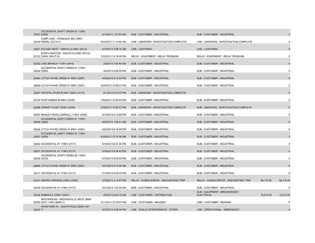
32567OCCIDENTAL SWIFT CREEK #1 115KV (0260) 4/14/2013 1:27:53 AM SUB - CUSTOMER - INDUSTRIAL SUB - CUSTOMER - INDUSTRIAL 0
32633CAMP LAKE - FERNDALE SEC 69KV RADIAL (CLFX-1) 4/23/2013 11:14:40 AM LINE - UNKNOWN - INVESTIGATION COMPLETE LINE - UNKNOWN - INVESTIGATION COMPLETE 0
32821 DELAND WEST - UMATILLA 69KV (ED-2) 5/19/2013 3:48:16 AM LINE - LIGHTNING - LINE - LIGHTNING - 0
32122NORTH BARTOW - SOUTH ELOISE (TECO) 230KV (WLXT-2) 1/22/2013 10:16:00 PM RELAY - EQUIPMENT - RELAY PROBLEM RELAY - EQUIPMENT - RELAY PROBLEM 0
32183 LAKE BRANCH 115KV (0475) 2/6/2013 7:54:59 AM SUB - CUSTOMER - INDUSTRIAL SUB - CUSTOMER - INDUSTRIAL 0
32524OCCIDENTAL SWIFT CREEK #1 115KV (0260) 4/6/2013 9:56:35 PM SUB - CUSTOMER - INDUSTRIAL SUB - CUSTOMER - INDUSTRIAL 0
32682 LITTLE PAYNE CREEK #1 69KV (0287) 4/30/2013 6:10:05 PM SUB - CUSTOMER - INDUSTRIAL SUB - CUSTOMER - INDUSTRIAL 0
32866 LITTLE PAYNE CREEK #1 69KV (0287) 5/20/2013 10:58:37 PM SUB - CUSTOMER - INDUSTRIAL SUB - CUSTOMER - INDUSTRIAL 0
32957 CRYSTAL RIVER PLANT 230KV (0171) 6/1/2013 9:31:07 PM SUB - UNKNOWN - INVESTIGATION COMPLETE - - 0
32134 FORT GREEN #4 69KV (0335) 1/24/2013 10:09:00 PM SUB - CUSTOMER - INDUSTRIAL SUB - CUSTOMER - INDUSTRIAL 0
32288 DEBARY PLANT 230KV (0246) 2/26/2013 10:46:37 PM SUB - UNKNOWN - INVESTIGATION COMPLETE SUB - UNKNOWN - INVESTIGATION COMPLETE 0
32367 MANLEY ROAD (CARGILL) 115KV (0004) 3/12/2013 6:12:56 PM SUB - CUSTOMER - INDUSTRIAL SUB - CUSTOMER - INDUSTRIAL 0
32608OCCIDENTAL SWIFT CREEK #1 115KV (0260) 4/22/2013 1:56:41 AM SUB - CUSTOMER - INDUSTRIAL SUB - CUSTOMER - INDUSTRIAL 0
32624 LITTLE PAYNE CREEK #1 69KV (0287) 4/22/2013 8:16:09 PM SUB - CUSTOMER - INDUSTRIAL SUB - CUSTOMER - INDUSTRIAL 0
32657OCCIDENTAL SWIFT CREEK #1 115KV (0260) 4/29/2013 12:10:38 AM SUB - CUSTOMER - INDUSTRIAL SUB - CUSTOMER - INDUSTRIAL 0
32830 OCCIDENTAL #1 115KV (0177) 5/19/2013 8:21:26 PM SUB - CUSTOMER - INDUSTRIAL SUB - CUSTOMER - INDUSTRIAL 0
32831 OCCIDENTAL #1 115KV (0177) 5/19/2013 8:34:42 PM SUB - CUSTOMER - INDUSTRIAL SUB - CUSTOMER - INDUSTRIAL 0
32834OCCIDENTAL SWIFT CREEK #2 115KV (0272) 5/19/2013 8:45:26 PM SUB - CUSTOMER - INDUSTRIAL SUB - CUSTOMER - INDUSTRIAL 0
32869 LITTLE PAYNE CREEK #1 69KV (0287) 5/21/2013 9:13:06 AM SUB - CUSTOMER - INDUSTRIAL SUB - CUSTOMER - INDUSTRIAL 0
32211 OCCIDENTAL #1 115KV (0177) 2/14/2013 6:06:25 PM SUB - CUSTOMER - INDUSTRIAL SUB - CUSTOMER - INDUSTRIAL 0
32231 WINTER SPRINGS 230KV (0252) 2/18/2013 2:14:57 PM RELAY - HUMAN ERROR - INADVERTENT TRIP RELAY - HUMAN ERROR - INADVERTENT TRIP 58,170.00 58,170.00
32242 OCCIDENTAL #1 115KV (0177) 2/21/2013 7:37:04 AM SUB - CUSTOMER - INDUSTRIAL SUB - CUSTOMER - INDUSTRIAL 0
32308 SEMINOLE 230KV (0051) 2/5/2013 9:40:13 AM LINE - CUSTOMER - DISTRIBUTIONSUB - EQUIPMENT - BREAKER/DIST - ELECTRICAL 72,610.00 72,610.00
32356BROOKRIDGE - BROOKSVILLE WEST (BBW CKT) 115KV (BBW-1) 3/11/2013 12:18:37 PM LINE - CUSTOMER - REA/EMC LINE - CUSTOMER - REA/EMC 0
32422AVON PARK PL - SOUTH POLK 230KV (AF-1) 3/22/2013 3:56:00 PM LINE - PUBLIC INTERFERENCE - OTHER LINE - OPERATIONAL - EMERGENCY 0
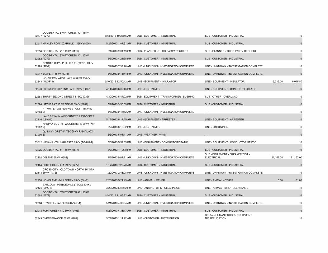
32777OCCIDENTAL SWIFT CREEK #2 115KV (0272) 5/13/2013 10:23:46 AM SUB - CUSTOMER - INDUSTRIAL SUB - CUSTOMER - INDUSTRIAL 0
32917 MANLEY ROAD (CARGILL) 115KV (0004) 5/27/2013 1:07:31 AM SUB - CUSTOMER - INDUSTRIAL SUB - CUSTOMER - INDUSTRIAL 0
32956 OCCIDENTAL #1 115KV (0177) 6/1/2013 9:01:19 PM SUB - PLANNED - THIRD PARTY REQUEST SUB - PLANNED - THIRD PARTY REQUEST 0
32982OCCIDENTAL SWIFT CREEK #2 115KV (0272) 6/3/2013 4:24:35 PM SUB - CUSTOMER - INDUSTRIAL SUB - CUSTOMER - INDUSTRIAL 0
32988DESOTO CITY - PHILLIPS PL (TECO) 69KV (AD-2) 6/4/2013 7:38:28 AM LINE - UNKNOWN - INVESTIGATION COMPLETE LINE - UNKNOWN - INVESTIGATION COMPLETE 0
33017 JASPER 115KV (0074) 6/6/2013 9:11:44 PM LINE - UNKNOWN - INVESTIGATION COMPLETE LINE - UNKNOWN - INVESTIGATION COMPLETE 0
32343HOLOPAW - WEST LAKE WALES 230KV (WLXF-3) 3/10/2013 12:50:42 AM LINE - EQUIPMENT - INSULATOR LINE - EQUIPMENT - INSULATOR 3,312.00 6,016.80
32570 PIEDMONT - SPRING LAKE 69KV (PSL-1) 4/14/2013 6:02:46 PM LINE - LIGHTNING - LINE - EQUIPMENT - CONDUCTOR/STATIC 0
32684 THIRTY SECOND STREET 115KV (0366) 4/30/2013 5:47:02 PM SUB - EQUIPMENT - TRANSFORMER - BUSHING SUB - OTHER - OVERLOAD 0
32686 LITTLE PAYNE CREEK #1 69KV (0287) 5/1/2013 3:50:09 PM SUB - CUSTOMER - INDUSTRIAL SUB - CUSTOMER - INDUSTRIAL 0
32703FT WHITE - JASPER WEST CKT 115KV (IJ-2) 5/3/2013 9:48:52 AM LINE - UNKNOWN - INVESTIGATION COMPLETE - - 0
32816LAKE BRYAN - WINDERMERE 230KV CKT 2 (LBW-1) 5/17/2013 6:17:15 AM LINE - EQUIPMENT - ARRESTER LINE - EQUIPMENT - ARRESTER 0
32967APOPKA SOUTH - WOODSMERE 69KV (WP-2) 6/2/2013 8:10:32 PM LINE - LIGHTNING - LINE - LIGHTNING - 0
33005QUINCY - GRETNA TEC 69KV RADIAL (QX-3) 6/6/2013 5:04:41 AM LINE - WEATHER - WIND - - 0
33012 HAVANA - TALLAHASSEE 69KV (TQ-HH-1) 6/6/2013 5:52:35 PM LINE - EQUIPMENT - CONDUCTOR/STATIC LINE - EQUIPMENT - CONDUCTOR/STATIC 0
33025 OCCIDENTAL #1 115KV (0177) 6/7/2013 1:19:00 PM SUB - CUSTOMER - INDUSTRIAL SUB - CUSTOMER - INDUSTRIAL 0
32102 DELAND 69KV (0301) 1/5/2013 9:01:21 AM LINE - UNKNOWN - INVESTIGATION COMPLETESUB - EQUIPMENT - BREAKER/DIST - ELECTRICAL 121,162.00 121,162.00
32104 FORT GREEN #11 69KV (0472) 1/17/2013 7:20:20 AM SUB - CUSTOMER - INDUSTRIAL SUB - CUSTOMER - INDUSTRIAL 0
32113CROSS CITY - OLD TOWN NORTH SW STA 69KV (TC-2) 1/20/2013 2:48:08 PM LINE - UNKNOWN - INVESTIGATION COMPLETE LINE - UNKNOWN - INVESTIGATION COMPLETE 0
32258 HOMELAND - MULBERRY 69KV (BH-2) 2/25/2013 5:24:45 AM LINE - ANIMAL - OTHER LINE - ANIMAL - OTHER 0.00 61.00
32424BARCOLA - PEBBLEDALE (TECO) 230KV (BPX-1) 3/22/2013 6:06:12 PM LINE - ANIMAL - BIRD - CLEARANCE LINE - ANIMAL - BIRD - CLEARANCE 0
32568OCCIDENTAL SWIFT CREEK #2 115KV (0272) 4/14/2013 11:03:22 AM SUB - CUSTOMER - INDUSTRIAL SUB - CUSTOMER - INDUSTRIAL 0
32868 FT WHITE - JASPER 69KV (JF-1) 5/21/2013 4:30:54 AM LINE - UNKNOWN - INVESTIGATION COMPLETE LINE - UNKNOWN - INVESTIGATION COMPLETE 0
32918 FORT GREEN #10 69KV (0463) 5/27/2013 4:38:17 AM SUB - CUSTOMER - INDUSTRIAL SUB - CUSTOMER - INDUSTRIAL 0
32949 CYPRESSWOOD 69KV (0267) 5/21/2013 1:11:22 AM LINE - CUSTOMER - DISTRIBUTIONRELAY - HUMAN ERROR - EQUIPMENT MISAPPLICATION 0
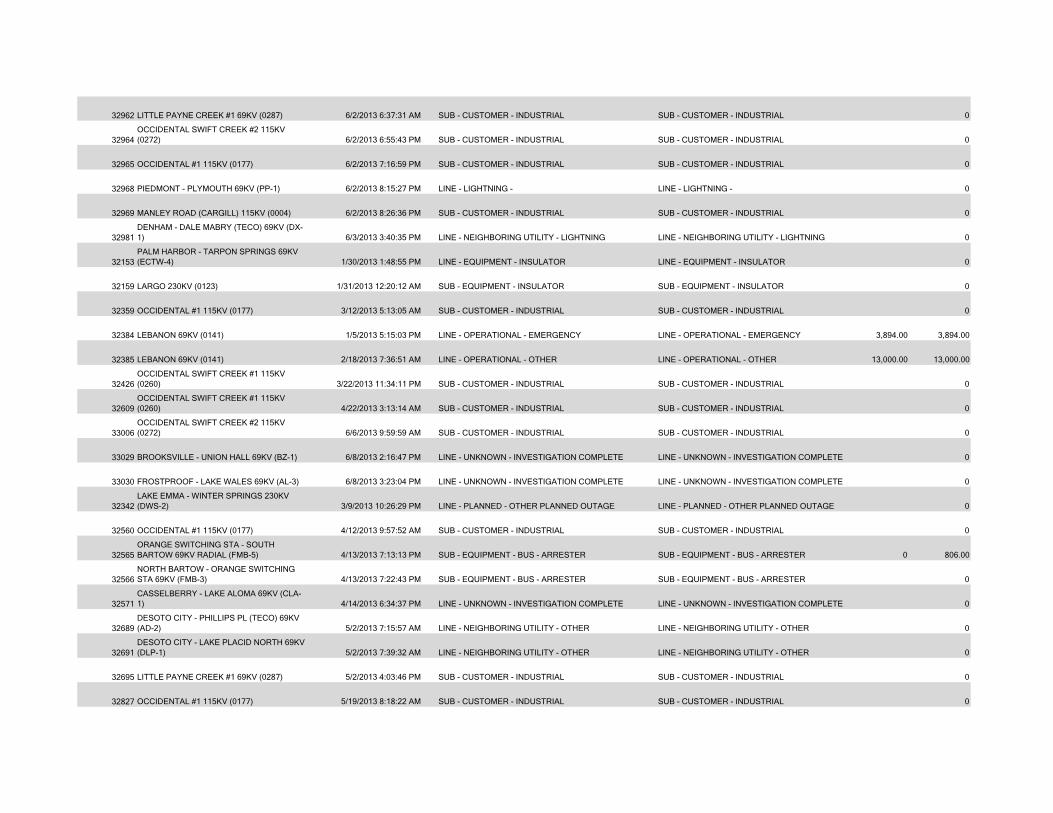
32962 LITTLE PAYNE CREEK #1 69KV (0287) 6/2/2013 6:37:31 AM SUB - CUSTOMER - INDUSTRIAL SUB - CUSTOMER - INDUSTRIAL 0
32964OCCIDENTAL SWIFT CREEK #2 115KV (0272) 6/2/2013 6:55:43 PM SUB - CUSTOMER - INDUSTRIAL SUB - CUSTOMER - INDUSTRIAL 0
32965 OCCIDENTAL #1 115KV (0177) 6/2/2013 7:16:59 PM SUB - CUSTOMER - INDUSTRIAL SUB - CUSTOMER - INDUSTRIAL 0
32968 PIEDMONT - PLYMOUTH 69KV (PP-1) 6/2/2013 8:15:27 PM LINE - LIGHTNING - LINE - LIGHTNING - 0
32969 MANLEY ROAD (CARGILL) 115KV (0004) 6/2/2013 8:26:36 PM SUB - CUSTOMER - INDUSTRIAL SUB - CUSTOMER - INDUSTRIAL 0
32981DENHAM - DALE MABRY (TECO) 69KV (DX-1) 6/3/2013 3:40:35 PM LINE - NEIGHBORING UTILITY - LIGHTNING LINE - NEIGHBORING UTILITY - LIGHTNING 0
32153PALM HARBOR - TARPON SPRINGS 69KV (ECTW-4) 1/30/2013 1:48:55 PM LINE - EQUIPMENT - INSULATOR LINE - EQUIPMENT - INSULATOR 0
32159 LARGO 230KV (0123) 1/31/2013 12:20:12 AM SUB - EQUIPMENT - INSULATOR SUB - EQUIPMENT - INSULATOR 0
32359 OCCIDENTAL #1 115KV (0177) 3/12/2013 5:13:05 AM SUB - CUSTOMER - INDUSTRIAL SUB - CUSTOMER - INDUSTRIAL 0
32384 LEBANON 69KV (0141) 1/5/2013 5:15:03 PM LINE - OPERATIONAL - EMERGENCY LINE - OPERATIONAL - EMERGENCY 3,894.00 3,894.00
32385 LEBANON 69KV (0141) 2/18/2013 7:36:51 AM LINE - OPERATIONAL - OTHER LINE - OPERATIONAL - OTHER 13,000.00 13,000.00
32426OCCIDENTAL SWIFT CREEK #1 115KV (0260) 3/22/2013 11:34:11 PM SUB - CUSTOMER - INDUSTRIAL SUB - CUSTOMER - INDUSTRIAL 0
32609OCCIDENTAL SWIFT CREEK #1 115KV (0260) 4/22/2013 3:13:14 AM SUB - CUSTOMER - INDUSTRIAL SUB - CUSTOMER - INDUSTRIAL 0
33006OCCIDENTAL SWIFT CREEK #2 115KV (0272) 6/6/2013 9:59:59 AM SUB - CUSTOMER - INDUSTRIAL SUB - CUSTOMER - INDUSTRIAL 0
33029 BROOKSVILLE - UNION HALL 69KV (BZ-1) 6/8/2013 2:16:47 PM LINE - UNKNOWN - INVESTIGATION COMPLETE LINE - UNKNOWN - INVESTIGATION COMPLETE 0
33030 FROSTPROOF - LAKE WALES 69KV (AL-3) 6/8/2013 3:23:04 PM LINE - UNKNOWN - INVESTIGATION COMPLETE LINE - UNKNOWN - INVESTIGATION COMPLETE 0
32342LAKE EMMA - WINTER SPRINGS 230KV (DWS-2) 3/9/2013 10:26:29 PM LINE - PLANNED - OTHER PLANNED OUTAGE LINE - PLANNED - OTHER PLANNED OUTAGE 0
32560 OCCIDENTAL #1 115KV (0177) 4/12/2013 9:57:52 AM SUB - CUSTOMER - INDUSTRIAL SUB - CUSTOMER - INDUSTRIAL 0
32565ORANGE SWITCHING STA - SOUTH BARTOW 69KV RADIAL (FMB-5) 4/13/2013 7:13:13 PM SUB - EQUIPMENT - BUS - ARRESTER SUB - EQUIPMENT - BUS - ARRESTER 0 806.00
32566NORTH BARTOW - ORANGE SWITCHING STA 69KV (FMB-3) 4/13/2013 7:22:43 PM SUB - EQUIPMENT - BUS - ARRESTER SUB - EQUIPMENT - BUS - ARRESTER 0
32571CASSELBERRY - LAKE ALOMA 69KV (CLA-1) 4/14/2013 6:34:37 PM LINE - UNKNOWN - INVESTIGATION COMPLETE LINE - UNKNOWN - INVESTIGATION COMPLETE 0
32689DESOTO CITY - PHILLIPS PL (TECO) 69KV (AD-2) 5/2/2013 7:15:57 AM LINE - NEIGHBORING UTILITY - OTHER LINE - NEIGHBORING UTILITY - OTHER 0
32691DESOTO CITY - LAKE PLACID NORTH 69KV (DLP-1) 5/2/2013 7:39:32 AM LINE - NEIGHBORING UTILITY - OTHER LINE - NEIGHBORING UTILITY - OTHER 0
32695 LITTLE PAYNE CREEK #1 69KV (0287) 5/2/2013 4:03:46 PM SUB - CUSTOMER - INDUSTRIAL SUB - CUSTOMER - INDUSTRIAL 0
32827 OCCIDENTAL #1 115KV (0177) 5/19/2013 8:18:22 AM SUB - CUSTOMER - INDUSTRIAL SUB - CUSTOMER - INDUSTRIAL 0
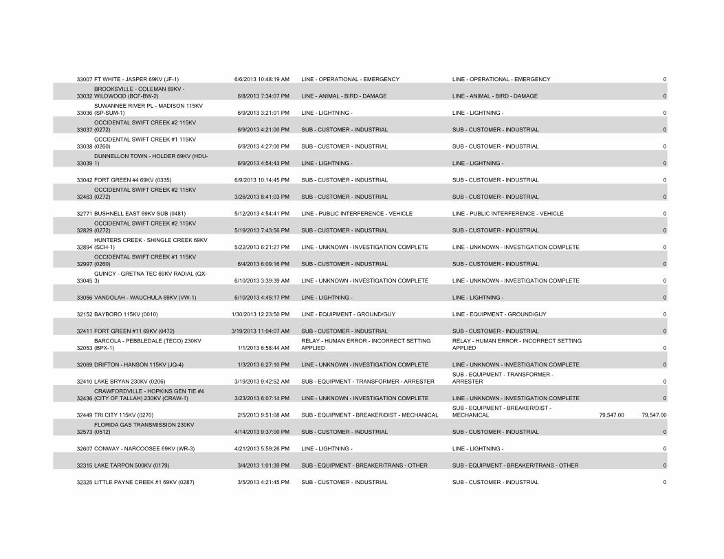
33007 FT WHITE - JASPER 69KV (JF-1) 6/6/2013 10:48:19 AM LINE - OPERATIONAL - EMERGENCY LINE - OPERATIONAL - EMERGENCY 0
33032BROOKSVILLE - COLEMAN 69KV - WILDWOOD (BCF-BW-2) 6/8/2013 7:34:07 PM LINE - ANIMAL - BIRD - DAMAGE LINE - ANIMAL - BIRD - DAMAGE 0
33036SUWANNEE RIVER PL - MADISON 115KV (SP-SUM-1) 6/9/2013 3:21:01 PM LINE - LIGHTNING - LINE - LIGHTNING - 0
33037OCCIDENTAL SWIFT CREEK #2 115KV (0272) 6/9/2013 4:21:00 PM SUB - CUSTOMER - INDUSTRIAL SUB - CUSTOMER - INDUSTRIAL 0
33038OCCIDENTAL SWIFT CREEK #1 115KV (0260) 6/9/2013 4:27:00 PM SUB - CUSTOMER - INDUSTRIAL SUB - CUSTOMER - INDUSTRIAL 0
33039DUNNELLON TOWN - HOLDER 69KV (HDU-1) 6/9/2013 4:54:43 PM LINE - LIGHTNING - LINE - LIGHTNING - 0
33042 FORT GREEN #4 69KV (0335) 6/9/2013 10:14:45 PM SUB - CUSTOMER - INDUSTRIAL SUB - CUSTOMER - INDUSTRIAL 0
32463OCCIDENTAL SWIFT CREEK #2 115KV (0272) 3/26/2013 8:41:03 PM SUB - CUSTOMER - INDUSTRIAL SUB - CUSTOMER - INDUSTRIAL 0
32771 BUSHNELL EAST 69KV SUB (0481) 5/12/2013 4:54:41 PM LINE - PUBLIC INTERFERENCE - VEHICLE LINE - PUBLIC INTERFERENCE - VEHICLE 0
32829OCCIDENTAL SWIFT CREEK #2 115KV (0272) 5/19/2013 7:43:56 PM SUB - CUSTOMER - INDUSTRIAL SUB - CUSTOMER - INDUSTRIAL 0
32894HUNTERS CREEK - SHINGLE CREEK 69KV (SCH-1) 5/22/2013 6:21:27 PM LINE - UNKNOWN - INVESTIGATION COMPLETE LINE - UNKNOWN - INVESTIGATION COMPLETE 0
32997OCCIDENTAL SWIFT CREEK #1 115KV (0260) 6/4/2013 6:09:16 PM SUB - CUSTOMER - INDUSTRIAL SUB - CUSTOMER - INDUSTRIAL 0
33045QUINCY - GRETNA TEC 69KV RADIAL (QX-3) 6/10/2013 3:39:39 AM LINE - UNKNOWN - INVESTIGATION COMPLETE LINE - UNKNOWN - INVESTIGATION COMPLETE 0
33056 VANDOLAH - WAUCHULA 69KV (VW-1) 6/10/2013 4:45:17 PM LINE - LIGHTNING - LINE - LIGHTNING - 0
32152 BAYBORO 115KV (0010) 1/30/2013 12:23:50 PM LINE - EQUIPMENT - GROUND/GUY LINE - EQUIPMENT - GROUND/GUY 0
32411 FORT GREEN #11 69KV (0472) 3/19/2013 11:04:07 AM SUB - CUSTOMER - INDUSTRIAL SUB - CUSTOMER - INDUSTRIAL 0
32053BARCOLA - PEBBLEDALE (TECO) 230KV (BPX-1) 1/1/2013 6:58:44 AM
RELAY - HUMAN ERROR - INCORRECT SETTING APPLIED
RELAY - HUMAN ERROR - INCORRECT SETTING APPLIED 0
32069 DRIFTON - HANSON 115KV (JQ-4) 1/3/2013 6:27:10 PM LINE - UNKNOWN - INVESTIGATION COMPLETE LINE - UNKNOWN - INVESTIGATION COMPLETE 0
32410 LAKE BRYAN 230KV (0206) 3/19/2013 9:42:52 AM SUB - EQUIPMENT - TRANSFORMER - ARRESTERSUB - EQUIPMENT - TRANSFORMER - ARRESTER 0
32436CRAWFORDVILLE - HOPKINS GEN TIE #4 (CITY OF TALLAH) 230KV (CRAW-1) 3/23/2013 6:07:14 PM LINE - UNKNOWN - INVESTIGATION COMPLETE LINE - UNKNOWN - INVESTIGATION COMPLETE 0
32449 TRI CITY 115KV (0270) 2/5/2013 9:51:08 AM SUB - EQUIPMENT - BREAKER/DIST - MECHANICALSUB - EQUIPMENT - BREAKER/DIST - MECHANICAL 79,547.00 79,547.00
32573FLORIDA GAS TRANSMISSION 230KV (0512) 4/14/2013 9:37:00 PM SUB - CUSTOMER - INDUSTRIAL SUB - CUSTOMER - INDUSTRIAL 0
32607 CONWAY - NARCOOSEE 69KV (WR-3) 4/21/2013 5:59:26 PM LINE - LIGHTNING - LINE - LIGHTNING - 0
32315 LAKE TARPON 500KV (0179) 3/4/2013 1:01:39 PM SUB - EQUIPMENT - BREAKER/TRANS - OTHER SUB - EQUIPMENT - BREAKER/TRANS - OTHER 0
32325 LITTLE PAYNE CREEK #1 69KV (0287) 3/5/2013 4:21:45 PM SUB - CUSTOMER - INDUSTRIAL SUB - CUSTOMER - INDUSTRIAL 0
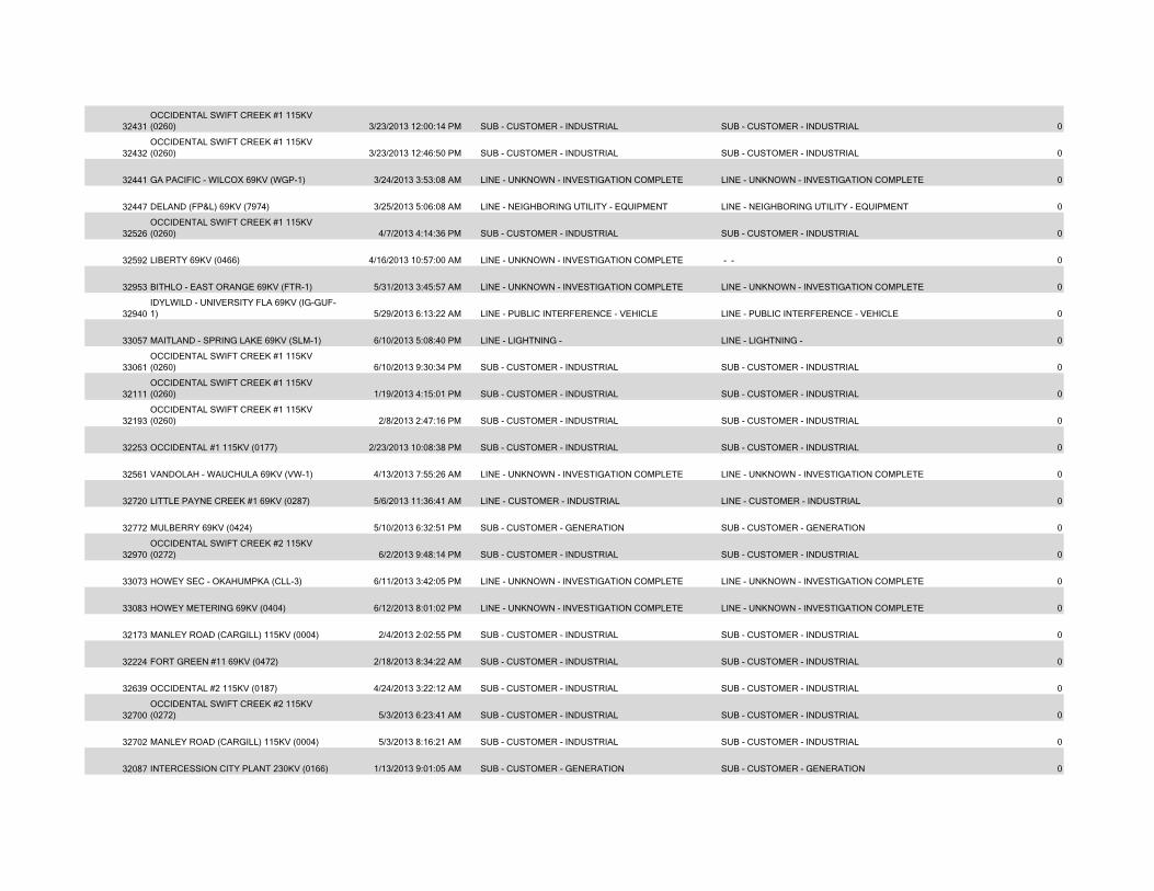
32431OCCIDENTAL SWIFT CREEK #1 115KV (0260) 3/23/2013 12:00:14 PM SUB - CUSTOMER - INDUSTRIAL SUB - CUSTOMER - INDUSTRIAL 0
32432OCCIDENTAL SWIFT CREEK #1 115KV (0260) 3/23/2013 12:46:50 PM SUB - CUSTOMER - INDUSTRIAL SUB - CUSTOMER - INDUSTRIAL 0
32441 GA PACIFIC - WILCOX 69KV (WGP-1) 3/24/2013 3:53:08 AM LINE - UNKNOWN - INVESTIGATION COMPLETE LINE - UNKNOWN - INVESTIGATION COMPLETE 0
32447 DELAND (FP&L) 69KV (7974) 3/25/2013 5:06:08 AM LINE - NEIGHBORING UTILITY - EQUIPMENT LINE - NEIGHBORING UTILITY - EQUIPMENT 0
32526OCCIDENTAL SWIFT CREEK #1 115KV (0260) 4/7/2013 4:14:36 PM SUB - CUSTOMER - INDUSTRIAL SUB - CUSTOMER - INDUSTRIAL 0
32592 LIBERTY 69KV (0466) 4/16/2013 10:57:00 AM LINE - UNKNOWN - INVESTIGATION COMPLETE - - 0
32953 BITHLO - EAST ORANGE 69KV (FTR-1) 5/31/2013 3:45:57 AM LINE - UNKNOWN - INVESTIGATION COMPLETE LINE - UNKNOWN - INVESTIGATION COMPLETE 0
32940IDYLWILD - UNIVERSITY FLA 69KV (IG-GUF-1) 5/29/2013 6:13:22 AM LINE - PUBLIC INTERFERENCE - VEHICLE LINE - PUBLIC INTERFERENCE - VEHICLE 0
33057 MAITLAND - SPRING LAKE 69KV (SLM-1) 6/10/2013 5:08:40 PM LINE - LIGHTNING - LINE - LIGHTNING - 0
33061OCCIDENTAL SWIFT CREEK #1 115KV (0260) 6/10/2013 9:30:34 PM SUB - CUSTOMER - INDUSTRIAL SUB - CUSTOMER - INDUSTRIAL 0
32111OCCIDENTAL SWIFT CREEK #1 115KV (0260) 1/19/2013 4:15:01 PM SUB - CUSTOMER - INDUSTRIAL SUB - CUSTOMER - INDUSTRIAL 0
32193OCCIDENTAL SWIFT CREEK #1 115KV (0260) 2/8/2013 2:47:16 PM SUB - CUSTOMER - INDUSTRIAL SUB - CUSTOMER - INDUSTRIAL 0
32253 OCCIDENTAL #1 115KV (0177) 2/23/2013 10:08:38 PM SUB - CUSTOMER - INDUSTRIAL SUB - CUSTOMER - INDUSTRIAL 0
32561 VANDOLAH - WAUCHULA 69KV (VW-1) 4/13/2013 7:55:26 AM LINE - UNKNOWN - INVESTIGATION COMPLETE LINE - UNKNOWN - INVESTIGATION COMPLETE 0
32720 LITTLE PAYNE CREEK #1 69KV (0287) 5/6/2013 11:36:41 AM LINE - CUSTOMER - INDUSTRIAL LINE - CUSTOMER - INDUSTRIAL 0
32772 MULBERRY 69KV (0424) 5/10/2013 6:32:51 PM SUB - CUSTOMER - GENERATION SUB - CUSTOMER - GENERATION 0
32970OCCIDENTAL SWIFT CREEK #2 115KV (0272) 6/2/2013 9:48:14 PM SUB - CUSTOMER - INDUSTRIAL SUB - CUSTOMER - INDUSTRIAL 0
33073 HOWEY SEC - OKAHUMPKA (CLL-3) 6/11/2013 3:42:05 PM LINE - UNKNOWN - INVESTIGATION COMPLETE LINE - UNKNOWN - INVESTIGATION COMPLETE 0
33083 HOWEY METERING 69KV (0404) 6/12/2013 8:01:02 PM LINE - UNKNOWN - INVESTIGATION COMPLETE LINE - UNKNOWN - INVESTIGATION COMPLETE 0
32173 MANLEY ROAD (CARGILL) 115KV (0004) 2/4/2013 2:02:55 PM SUB - CUSTOMER - INDUSTRIAL SUB - CUSTOMER - INDUSTRIAL 0
32224 FORT GREEN #11 69KV (0472) 2/18/2013 8:34:22 AM SUB - CUSTOMER - INDUSTRIAL SUB - CUSTOMER - INDUSTRIAL 0
32639 OCCIDENTAL #2 115KV (0187) 4/24/2013 3:22:12 AM SUB - CUSTOMER - INDUSTRIAL SUB - CUSTOMER - INDUSTRIAL 0
32700OCCIDENTAL SWIFT CREEK #2 115KV (0272) 5/3/2013 6:23:41 AM SUB - CUSTOMER - INDUSTRIAL SUB - CUSTOMER - INDUSTRIAL 0
32702 MANLEY ROAD (CARGILL) 115KV (0004) 5/3/2013 8:16:21 AM SUB - CUSTOMER - INDUSTRIAL SUB - CUSTOMER - INDUSTRIAL 0
32087 INTERCESSION CITY PLANT 230KV (0166) 1/13/2013 9:01:05 AM SUB - CUSTOMER - GENERATION SUB - CUSTOMER - GENERATION 0
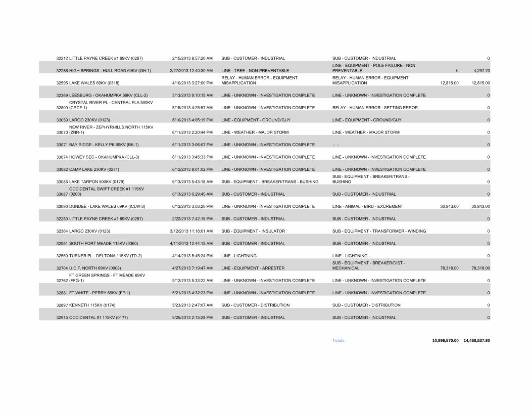
32212 LITTLE PAYNE CREEK #1 69KV (0287) 2/15/2013 8:57:26 AM SUB - CUSTOMER - INDUSTRIAL SUB - CUSTOMER - INDUSTRIAL 0
32286 HIGH SPRINGS - HULL ROAD 69KV (GH-1) 2/27/2013 12:40:30 AM LINE - TREE - NON-PREVENTABLELINE - EQUIPMENT - POLE FAILURE - NON PREVENTABLE 0 4,297.70
32595 LAKE WALES 69KV (0318) 4/10/2013 3:27:00 PMRELAY - HUMAN ERROR - EQUIPMENT MISAPPLICATION
RELAY - HUMAN ERROR - EQUIPMENT MISAPPLICATION 12,815.00 12,815.00
32369 LEESBURG - OKAHUMPKA 69KV (CLL-2) 3/13/2013 9:10:15 AM LINE - UNKNOWN - INVESTIGATION COMPLETE LINE - UNKNOWN - INVESTIGATION COMPLETE 0
32800CRYSTAL RIVER PL - CENTRAL FLA 500KV (CRCF-1) 5/15/2013 4:25:57 AM LINE - UNKNOWN - INVESTIGATION COMPLETE RELAY - HUMAN ERROR - SETTING ERROR 0
33059 LARGO 230KV (0123) 6/10/2013 4:05:19 PM LINE - EQUIPMENT - GROUND/GUY LINE - EQUIPMENT - GROUND/GUY 0
33070NEW RIVER - ZEPHYRHILLS NORTH 115KV (ZNR-1) 6/11/2013 2:20:44 PM LINE - WEATHER - MAJOR STORM LINE - WEATHER - MAJOR STORM 0
33071 BAY RIDGE - KELLY PK 69KV (BK-1) 6/11/2013 3:06:07 PM LINE - UNKNOWN - INVESTIGATION COMPLETE - - 0
33074 HOWEY SEC - OKAHUMPKA (CLL-3) 6/11/2013 3:45:33 PM LINE - UNKNOWN - INVESTIGATION COMPLETE LINE - UNKNOWN - INVESTIGATION COMPLETE 0
33082 CAMP LAKE 230KV (0271) 6/12/2013 8:01:02 PM LINE - UNKNOWN - INVESTIGATION COMPLETE LINE - UNKNOWN - INVESTIGATION COMPLETE 0
33086 LAKE TARPON 500KV (0179) 6/13/2013 5:43:18 AM SUB - EQUIPMENT - BREAKER/TRANS - BUSHINGSUB - EQUIPMENT - BREAKER/TRANS - BUSHING 0
33087OCCIDENTAL SWIFT CREEK #1 115KV (0260) 6/13/2013 6:29:45 AM SUB - CUSTOMER - INDUSTRIAL SUB - CUSTOMER - INDUSTRIAL 0
33090 DUNDEE - LAKE WALES 69KV (ICLW-3) 6/13/2013 3:03:20 PM LINE - UNKNOWN - INVESTIGATION COMPLETE LINE - ANIMAL - BIRD - EXCREMENT 30,843.00 30,843.00
32250 LITTLE PAYNE CREEK #1 69KV (0287) 2/22/2013 7:42:19 PM SUB - CUSTOMER - INDUSTRIAL SUB - CUSTOMER - INDUSTRIAL 0
32364 LARGO 230KV (0123) 3/12/2013 11:16:01 AM SUB - EQUIPMENT - INSULATOR SUB - EQUIPMENT - TRANSFORMER - WINDING 0
32551 SOUTH FORT MEADE 115KV (0360) 4/11/2013 12:44:13 AM SUB - CUSTOMER - INDUSTRIAL SUB - CUSTOMER - INDUSTRIAL 0
32569 TURNER PL - DELTONA 115KV (TD-2) 4/14/2013 5:45:24 PM LINE - LIGHTNING - LINE - LIGHTNING - 0
32704 U.C.F. NORTH 69KV (0008) 4/27/2013 7:19:47 AM LINE - EQUIPMENT - ARRESTERSUB - EQUIPMENT - BREAKER/DIST - MECHANICAL 78,318.00 78,318.00
32762FT GREEN SPRINGS - FT MEADE 69KV (FFG-1) 5/12/2013 5:33:22 AM LINE - UNKNOWN - INVESTIGATION COMPLETE LINE - UNKNOWN - INVESTIGATION COMPLETE 0
32881 FT WHITE - PERRY 69KV (FP-1) 5/21/2013 4:32:23 PM LINE - UNKNOWN - INVESTIGATION COMPLETE LINE - UNKNOWN - INVESTIGATION COMPLETE 0
32897 KENNETH 115KV (0174) 5/23/2013 2:47:07 AM SUB - CUSTOMER - DISTRIBUTION SUB - CUSTOMER - DISTRIBUTION 0
32915 OCCIDENTAL #1 115KV (0177) 5/25/2013 2:15:28 PM SUB - CUSTOMER - INDUSTRIAL SUB - CUSTOMER - INDUSTRIAL 0
Totals 10,896,570.00 14,458,537.80

ATTACHMENT B
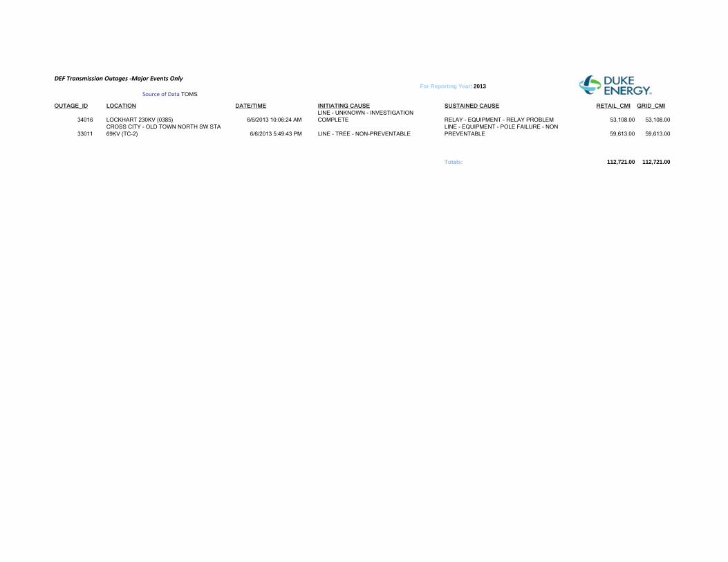
DEF Transmission Outages ‐Major Events Only
OUTAGE_ID LOCATION DATE/TIME INITIATING CAUSE SUSTAINED CAUSE RETAIL_CMI GRID_CMI
34016 LOCKHART 230KV (0385) 6/6/2013 10:06:24 AMLINE - UNKNOWN - INVESTIGATION COMPLETE RELAY - EQUIPMENT - RELAY PROBLEM 53,108.00 53,108.00
33011CROSS CITY - OLD TOWN NORTH SW STA 69KV (TC-2) 6/6/2013 5:49:43 PM LINE - TREE - NON-PREVENTABLE
LINE - EQUIPMENT - POLE FAILURE - NON PREVENTABLE 59,613.00 59,613.00
Totals: 112,721.00 112,721.00
Source of Data TOMSFor Reporting Year: 2013

ATTACHMENT C
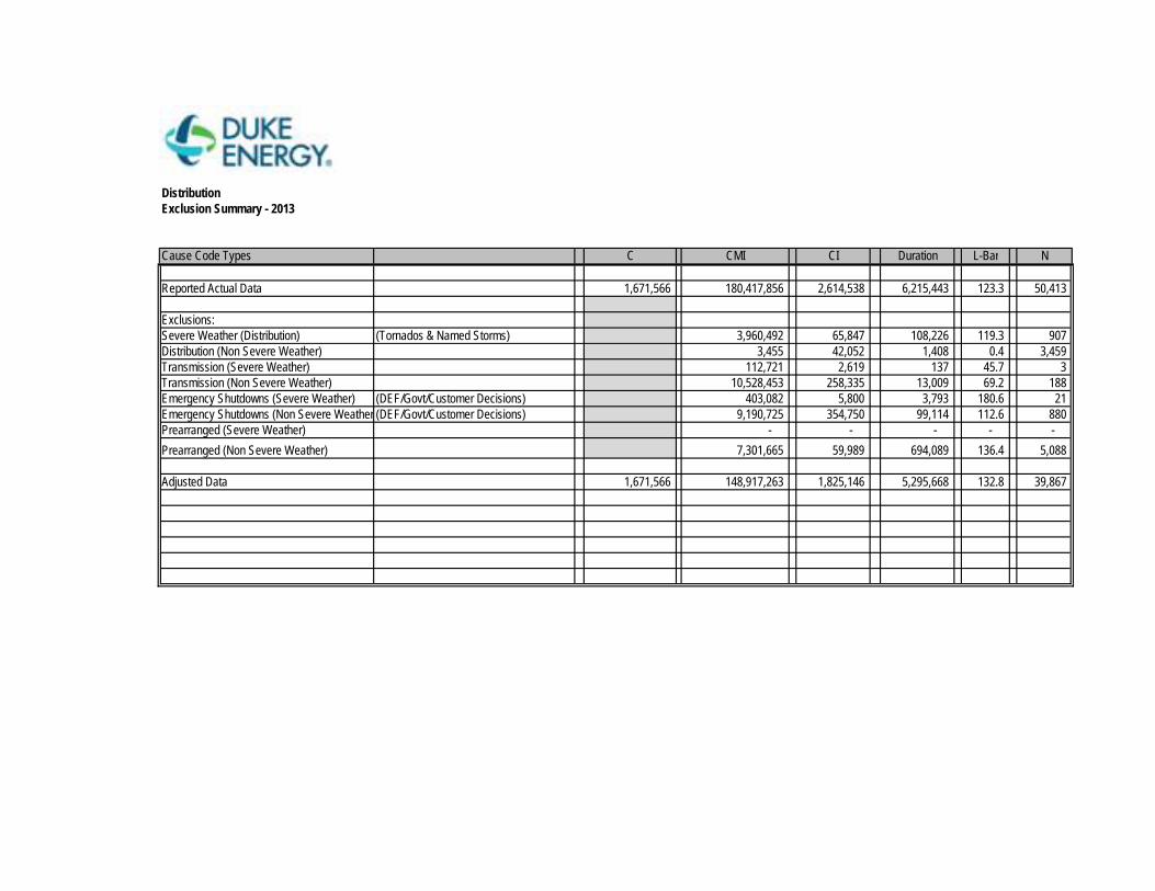
DistributionExclusion Summary - 2013
Cause Code Types C CMI CI Duration L-Bar N
Reported Actual Data 1,671,566 180,417,856 2,614,538 6,215,443 123.3 50,413
Exclusions:0-46,except 22 Severe Weather (Distribution) (Tornados & Named Storms) 3,960,492 65,847 108,226 119.3 907 All > 67 Distribution (Non Severe Weather) 3,455 42,052 1,408 0.4 3,459
Transmission (Severe Weather) 112,721 2,619 137 45.7 3 22,64 Transmission (Non Severe Weather) 10,528,453 258,335 13,009 69.2 188 22,64 Emergency Shutdowns (Severe Weather) (DEF/Govt/Customer Decisions) 403,082 5,800 3,793 180.6 21 60,61 Emergency Shutdowns (Non Severe Weather (DEF/Govt/Customer Decisions) 9,190,725 354,750 99,114 112.6 880 60,61 Prearranged (Severe Weather) - - - - -
Prearranged (Non Severe Weather) 7,301,665 59,989 694,089 136.4 5,088
Adjusted Data 1,671,566 148,917,263 1,825,146 5,295,668 132.8 39,867
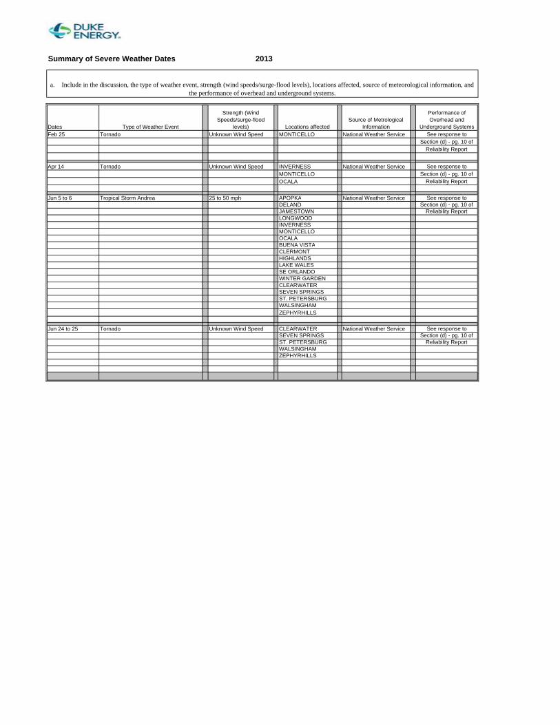
Summary of Severe Weather Dates 2013
Dates Type of Weather Event
Strength (Wind Speeds/surge-flood
levels) Locations affectedSource of Metrological
Information
Performance of Overhead and
Underground SystemsFeb 25 Tornado Unknown Wind Speed MONTICELLO National Weather Service See response to
Section (d) - pg. 10 ofReliability Report
Apr 14 Tornado Unknown Wind Speed INVERNESS National Weather Service See response to MONTICELLO Section (d) - pg. 10 ofOCALA Reliability Report
Jun 5 to 6 Tropical Storm Andrea 25 to 50 mph APOPKA National Weather Service See response to DELAND Section (d) - pg. 10 ofJAMESTOWN Reliability ReportLONGWOODINVERNESSMONTICELLOOCALABUENA VISTACLERMONTHIGHLANDSLAKE WALESSE ORLANDOWINTER GARDENCLEARWATERSEVEN SPRINGSST. PETERSBURGWALSINGHAMZEPHYRHILLS
Jun 24 to 25 Tornado Unknown Wind Speed CLEARWATER National Weather Service See response to SEVEN SPRINGS Section (d) - pg. 10 ofST. PETERSBURG Reliability ReportWALSINGHAMZEPHYRHILLS
a. Include in the discussion, the type of weather event, strength (wind speeds/surge-flood levels), locations affected, source of meteorological information, and the performance of overhead and underground systems.
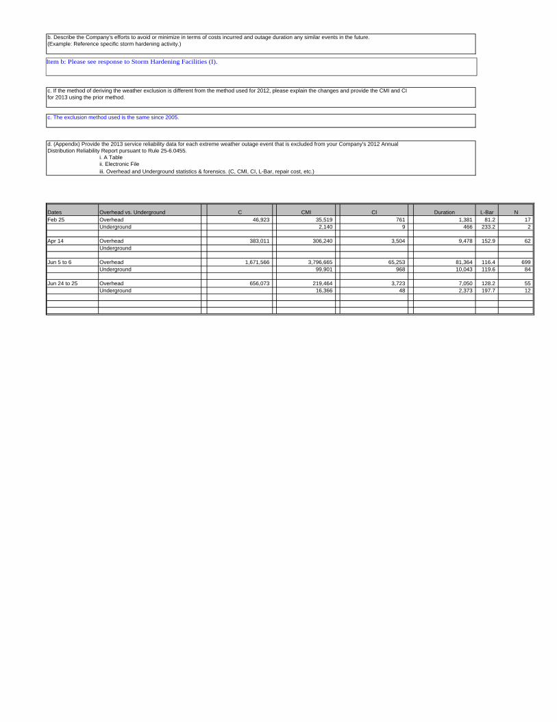
b. Describe the Company's efforts to avoid or minimize in terms of costs incurred and outage duration any similar events in the future.(Example: Reference specific storm hardening activity.)
c. If the method of deriving the weather exclusion is different from the method used for 2012, please explain the changes and provide the CMI and CIfor 2013 using the prior method.
c. The exclusion method used is the same since 2005.
d. (Appendix) Provide the 2013 service reliability data for each extreme weather outage event that is excluded from your Company's 2012 AnnualDistribution Reliability Report pursuant to Rule 25-6.0455.
i. A Tableii. Electronic Fileiii. Overhead and Underground statistics & forensics. (C, CMI, CI, L-Bar, repair cost, etc.)
Dates Overhead vs. Underground C CMI CI Duration L-Bar NFeb 25 Overhead 46,923 35,519 761 1,381 81.2 17
Underground 2,140 9 466 233.2 2
Apr 14 Overhead 383,011 306,240 3,504 9,478 152.9 62 Underground
Jun 5 to 6 Overhead 1,671,566 3,796,665 65,253 81,364 116.4 699 Underground 99,901 968 10,043 119.6 84
Jun 24 to 25 Overhead 656,073 219,464 3,723 7,050 128.2 55 Underground 16,366 48 2,373 197.7 12
Item b: Please see response to Storm Hardening Facilities (I).

ATTACHMENT D
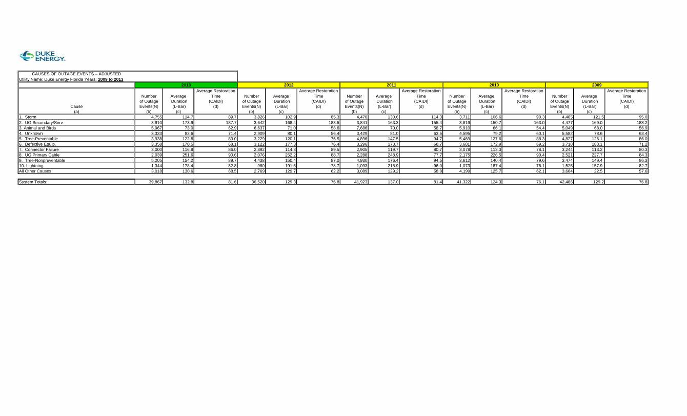
CAUSES OF OUTAGE EVENTS – ADJUSTEDUtility Name: Duke Energy Florida Years: 2009 to 2013
Average Restoration Average Restoration Average Restoration Average Restoration Average RestorationNumber Average Time Number Average Time Number Average Time Number Average Time Number Average Time
of Outage Duration (CAIDI) of Outage Duration (CAIDI) of Outage Duration (CAIDI) of Outage Duration (CAIDI) of Outage Duration (CAIDI)Cause Events(N) (L-Bar) (d) Events(N) (L-Bar) (d) Events(N) (L-Bar) (d) Events(N) (L-Bar) (d) Events(N) (L-Bar) (d)
(a) (b) (c) (b) (c) (b) (c) (b) (c) (b) (c)1. Storm 4,755 114.7 89.7 3,826 102.9 85.3 4,470 130.6 114.3 3,711 106.6 90.3 4,405 121.5 95.02. UG Secondary/Serv 3,910 173.9 187.7 3,642 168.4 183.5 3,841 163.3 155.4 3,819 150.7 163.0 4,477 169.0 188.23. Animal and Birds 5,967 73.0 62.9 6,637 71.0 58.6 7,686 70.0 58.7 5,910 66.1 54.4 5,049 68.0 56.94. Unknown 3,333 83.6 71.4 2,909 80.1 56.4 3,429 81.0 63.5 4,595 79.2 60.1 5,582 78.6 63.45. Tree-Preventable 3,938 122.8 83.0 3,229 120.1 76.5 4,896 147.5 94.7 5,469 127.6 88.3 4,827 126.1 86.06. Defective Equip. 3,358 170.5 68.1 3,122 177.3 76.4 3,296 173.7 68.7 3,681 172.9 69.2 3,718 183.1 71.27. Connector Failure 3,000 116.8 86.0 2,892 114.3 89.5 2,905 119.7 80.7 3,078 113.3 78.1 3,244 113.2 80.38. UG Primary Cable 2,039 251.6 90.6 2,076 252.2 88.7 2,288 248.9 77.7 2,175 226.5 90.4 2,521 227.7 84.39. Tree-Nonpreventable 5,205 154.2 89.7 4,438 150.4 87.0 4,930 176.4 94.5 3,612 140.4 79.6 3,474 149.4 86.310. Lightning 1,344 178.4 82.8 980 191.5 78.7 1,093 215.9 96.0 1,073 187.4 76.1 1,525 157.9 82.7All Other Causes 3,018 130.6 68.5 2,769 129.7 62.2 3,089 129.2 58.9 4,199 125.7 62.1 3,664 22.5 57.6 System Totals: 39,867 132.8 81.6 36,520 129.3 76.8 41,923 137.0 81.4 41,322 124.3 76.1 42,486 129.2 76.8
2013 2012 2011 2010 2009

ATTACHMENT E
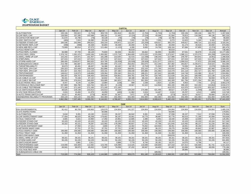
2014PROGRAM BUDGET 2 3 4 5 6 7 8 9 10 11 12 13
Jan-14 Feb-14 Mar-14 Apr-14 May-14 Jun-14 Jul-14 Aug-14 Sep-14 Oct-14 Nov-14 Dec-14 AnnualSI-AUTOMATION 100,106 252,822 (1,704) 303,729 201,918 49,203 (1,704) (1,704) (1,704) 100,106 100,106 166,772 1,267,946 SI-CAP REPL-CAP 139,059 157,285 102,588 189,181 11,443 (2,224) (2,224) 43,346 61,564 79,813 116,266 66,136 962,233 SI-CAPACITOR NEW-CAP 21,670 10,796 (78) 43,128 (78) (78) (78) (78) 10,796 10,756 (78) (78) 96,600 SI-DISC SWITCH-CAP (465) 7,024 16,380 20,156 (465) 7,033 10,783 7,035 3,273 12,623 5,160 5,160 93,697 SI-FEEDER STAND-CAP 184,036 242,948 290,623 326,319 378,972 112,347 (22,209) 429,017 392,379 449,617 548,714 (12,422) 3,320,341 SI-NETWORK REPL-CAP (498) (498) 30,338 50,894 30,338 20,059 9,782 30,338 20,059 61,173 40,616 20,059 670,092 SI-NEW ABB RECL-CAP 73,909 80,014 97,073 121,484 (1,122) 4,280 9,083 24,700 108,104 87,084 67,855 (2,374) 382,476 SI-POLE REINF-CAP - - 95,619 - - 95,619 - - 95,619 - - 95,619 738,483 SI-POLE REPL CLOSED 66,988 67,705 68,128 70,800 66,938 66,402 66,662 66,955 66,809 67,541 66,678 (3,124) 15,177,284 SI-POLE REPL OPEN 1,376,742 1,391,470 1,400,166 1,455,082 1,375,718 1,364,690 1,370,033 1,376,059 1,373,047 1,388,111 1,370,375 (64,208) 1,844,634 SI-SMALL WIRE UP-CAP 102,242 134,971 161,457 181,288 210,540 62,415 (12,338) 238,343 217,988 249,787 304,841 (6,901) 1,288,928 SI-STBPLRMVL 107,015 107,015 107,015 107,015 107,015 107,015 107,015 107,542 107,015 107,015 107,015 111,236 5,880,052 SI-STORM HARD-CAP 289,400 2,049,877 992,632 424,785 (35,928) (35,928) (35,928) 1,011,577 128,011 1,099,510 27,972 (35,928) 5,086,103 SI-SUBAQUEOUS CABLE 213,780 282,687 259,372 250,489 272,119 263,453 263,670 312,240 257,482 263,817 2,228,471 218,523 553,390 SI-TARGETRELIABILITY 30,673 40,491 48,437 54,386 63,162 18,725 (3,702) 71,503 65,397 74,936 91,452 (2,070) 2,884,081 SI-TRIP REPL 1PH-CAP 230,323 253,408 238,018 262,886 222,628 268,801 232,104 271,795 243,933 249,276 228,542 182,368 2,558,305 SI-TRIP REPL 3PH-CAP 204,307 224,783 211,133 233,191 197,480 238,438 205,886 241,093 216,379 221,118 202,727 161,769 1,895,336 SI-TRIP1PHMODEF 148,612 118,573 148,606 128,364 250,340 204,131 188,221 167,042 160,895 144,749 143,386 92,417 2,504,891 SI-TRIP3PHMODEF 196,407 156,707 196,400 169,648 330,851 269,781 248,754 220,765 212,639 191,302 189,499 122,138 1,316,403 SI-UG CABLE LG-CAP 55,331 73,166 67,132 64,832 70,431 68,188 68,244 80,815 66,642 68,282 576,781 56,559 6,781,471 SI-UG CABLE SM-CAP 285,039 376,916 345,830 333,985 362,825 351,270 351,559 416,320 343,309 351,756 2,971,294 291,365 76,582 SI-ELECTRONIC RECL-CAP 8,447 9,145 11,094 13,884 (128) 489 1,038 2,823 12,355 9,953 7,755 (271) 3,063,279 SI-HYDRAULIC RECLOSER REP 337,869 365,780 443,764 555,357 (5,128) 19,567 41,522 112,916 494,190 398,100 310,194 (10,852) 3,016,272 SI-UG CABLE TEST/REHAB 271,165 271,165 271,165 271,165 271,165 - - - 413,375 413,375 413,375 420,322 1,458,673 SI-UG SWITCHGEAR REPL 68,625 139,198 103,913 103,913 33,339 139,200 174,486 421,495 68,627 174,487 (1,949) 33,339 113,749 SI-VOLTAGE REGULATORS 2,024 19,450 11,979 16,959 (465) 11,982 2,024 14,467 2,024 29,257 4,513 (465) 113,749 SI-AUTO TRANS SWITCH-CAP 16,017 40,452 (273) 48,597 32,307 7,872 (273) (273) (273) 16,017 16,017 26,684 202,871 ENGINEERING RELIABILITY PROGRAMS 334,134 334,134 342,483 342,483 342,483 342,483 342,483 342,483 342,483 342,483 342,483 342,483 4,093,098 Sum: 4,862,956 7,207,485 6,059,292 6,144,001 4,788,697 4,055,213 3,614,893 6,008,615 5,482,418 6,662,045 10,480,061 2,274,255 67,441,020
Jan-14 Feb-14 Mar-14 Apr-14 May-14 Jun-14 Jul-14 Aug-14 Sep-14 Oct-14 Nov-14 Dec-14 Sum:ENV-ENVIRONMENTAL 91,412 80,709 100,963 126,579 134,904 141,227 134,904 134,904 134,904 134,904 134,904 134,904 1,485,218 SI-ATS INSPECTIONS - - - 84,996 - - - - 94,945 - - - 179,941 SI-AUTOMATION 5,634 9,391 43,190 15,023 28,157 46,942 9,391 8,451 37,558 28,157 7,512 37,558 276,964 SI-CAP INSPECT/MAINT-O&M 27,404 48,025 95,208 179,402 58,197 20,061 19,775 38,987 82,776 80,515 71,195 42,094 763,639 SI-FAULT INDICATOR 4,665 5,621 10,960 17,092 24,961 12,685 2,386 6,691 18,430 15,469 12,059 4,372 135,391 SI-FEEDER STAND-CAP 43,103 43,103 43,103 43,103 43,103 43,103 43,103 43,103 43,103 43,103 43,103 43,104 517,240 SI-FEEDER STAND-O&M 33,322 40,151 78,287 122,082 178,296 90,607 17,041 47,796 131,640 110,492 86,137 31,230 967,081 SI-IR SCAN INSP/MAINT-O&M - 27,550 17,101 3,800 27,551 13,302 75,052 104,503 48,451 18,051 35,150 13,302 383,813 SI-NETWORK MAINT-O&M - 37,701 37,701 37,701 37,701 32,987 32,987 36,131 28,275 34,558 40,842 32,987 389,571 SI-POLE INSPECT-O&M 199,080 199,080 199,080 199,080 199,080 199,080 199,080 199,080 199,080 199,080 199,080 199,080 2,388,960 SI-POLE TREAT-O&M 31,359 31,359 31,359 31,359 31,359 31,359 31,359 31,359 31,359 31,359 31,415 - 345,005 SI-RECLOSR MAINT-O&M - - - - - - - - 239,878 - - - 239,878 SI-SMALL WIRE UP-CAP 38,161 38,161 38,161 38,161 38,161 38,161 38,161 38,161 38,161 38,161 38,161 38,161 457,933 SI-STORM HARD-CAP 50,155 50,155 50,155 50,155 50,155 50,155 50,155 50,155 50,155 50,155 50,155 50,155 601,855 SI-SWITCHGEAR MAINT - 3,881 2,911 - 3,888 7,779 8,740 26,181 19,371 14,570 6,796 - 94,117 SI-TRIP1PHREMED-O&M 119,090 100,409 112,092 123,765 126,099 114,425 119,099 109,659 107,418 107,412 100,406 81,741 1,321,615 SI-TRIP3PHREMED-O&M 69,941 58,970 65,832 72,687 74,058 67,202 69,947 64,403 63,087 63,084 58,969 48,006 776,186 SI-VOLTAGE REG INSP - - - - - - - - - 38,885 - - 38,885 SI-SUBAQUEOUS CABLE OM - - - - - - - 189,061 - - - - 189,061 Sum: 713,326 774,266 926,103 1,144,985 1,055,670 909,075 851,180 1,128,625 1,368,591 1,007,955 915,884 756,694 11,552,353
CAPITAL
O&M

ATTACHMENT F
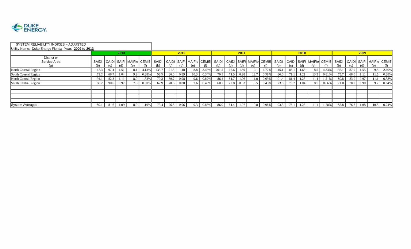
SYSTEM RELIABILITY INDICES – ADJUSTEDUtility Name: Duke Energy Florida Year: 2009 to 2013
District orService Area SAIDI CAIDI SAIFI MAIFIe CEMI5 SAIDI CAIDI SAIFI MAIFIe CEMI5 SAIDI CAIDI SAIFI MAIFIe CEMI5 SAIDI CAIDI SAIFI MAIFIe CEMI5 SAIDI CAIDI SAIFI MAIFIe CEMI5
(a) (b) (c) (d) (e) (f) (b) (c) (d) (e) (f) (b) (c) (d) (e) (f) (b) (c) (d) (e) (f) (b) (c) (d) (e) (f)North Coastal Region 147.3 97.4 1.51 8.1 4.13% 135.7 91.5 1.48 8.8 3.46% 201.2 106.6 1.89 9.1 4.77% 145.1 88.1 1.65 8.5 4.33% 136.1 87.9 1.55 9.8 2.60%South Coastal Region 71.2 68.7 1.04 9.9 0.38% 58.5 66.0 0.89 10.3 0.34% 70.3 71.5 0.98 12.7 0.38% 86.0 71.1 1.21 13.2 0.81% 75.7 68.0 1.11 11.5 0.38%North Central Region 91.1 82.3 1.11 8.9 1.53% 79.3 80.7 0.98 9.6 0.82% 86.4 81.7 1.06 11.0 0.69% 101.4 81.4 1.25 11.4 1.21% 80.8 83.0 0.97 11.1 0.53%South Central Region 88.2 90.6 0.97 7.8 0.80% 62.9 78.6 0.80 7.6 0.49% 60.7 72.8 0.83 8.5 0.43% 73.5 70.7 1.04 8.5 0.66% 71.0 78.9 0.90 9.7 0.64%
System Averages 89.1 81.6 1.09 8.9 1.19% 73.4 76.8 0.96 9.3 0.85% 86.9 81.4 1.07 10.8 0.98% 93.3 76.1 1.23 11.1 1.28% 82.8 76.8 1.08 10.8 0.74%
2013 2012 2011 2010 2009

ATTACHMENT G
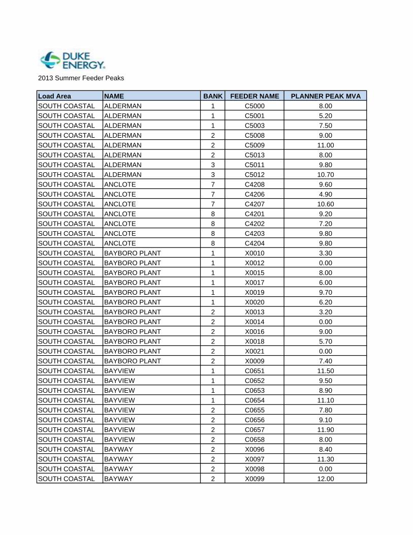
2013 Summer Feeder Peaks
Load Area NAME BANK FEEDER NAME PLANNER PEAK MVASOUTH COASTAL ALDERMAN 1 C5000 8.00SOUTH COASTAL ALDERMAN 1 C5001 5.20SOUTH COASTAL ALDERMAN 1 C5003 7.50SOUTH COASTAL ALDERMAN 2 C5008 9.00SOUTH COASTAL ALDERMAN 2 C5009 11.00SOUTH COASTAL ALDERMAN 2 C5013 8.00SOUTH COASTAL ALDERMAN 3 C5011 9.80SOUTH COASTAL ALDERMAN 3 C5012 10.70SOUTH COASTAL ANCLOTE 7 C4208 9.60SOUTH COASTAL ANCLOTE 7 C4206 4.90SOUTH COASTAL ANCLOTE 7 C4207 10.60SOUTH COASTAL ANCLOTE 8 C4201 9.20SOUTH COASTAL ANCLOTE 8 C4202 7.20SOUTH COASTAL ANCLOTE 8 C4203 9.80SOUTH COASTAL ANCLOTE 8 C4204 9.80SOUTH COASTAL BAYBORO PLANT 1 X0010 3.30SOUTH COASTAL BAYBORO PLANT 1 X0012 0.00SOUTH COASTAL BAYBORO PLANT 1 X0015 8.00SOUTH COASTAL BAYBORO PLANT 1 X0017 6.00SOUTH COASTAL BAYBORO PLANT 1 X0019 9.70SOUTH COASTAL BAYBORO PLANT 1 X0020 6.20SOUTH COASTAL BAYBORO PLANT 2 X0013 3.20SOUTH COASTAL BAYBORO PLANT 2 X0014 0.00SOUTH COASTAL BAYBORO PLANT 2 X0016 9.00SOUTH COASTAL BAYBORO PLANT 2 X0018 5.70SOUTH COASTAL BAYBORO PLANT 2 X0021 0.00SOUTH COASTAL BAYBORO PLANT 2 X0009 7.40SOUTH COASTAL BAYVIEW 1 C0651 11.50SOUTH COASTAL BAYVIEW 1 C0652 9.50SOUTH COASTAL BAYVIEW 1 C0653 8.90SOUTH COASTAL BAYVIEW 1 C0654 11.10SOUTH COASTAL BAYVIEW 2 C0655 7.80SOUTH COASTAL BAYVIEW 2 C0656 9.10SOUTH COASTAL BAYVIEW 2 C0657 11.90SOUTH COASTAL BAYVIEW 2 C0658 8.00SOUTH COASTAL BAYWAY 2 X0096 8.40SOUTH COASTAL BAYWAY 2 X0097 11.30SOUTH COASTAL BAYWAY 2 X0098 0.00SOUTH COASTAL BAYWAY 2 X0099 12.00
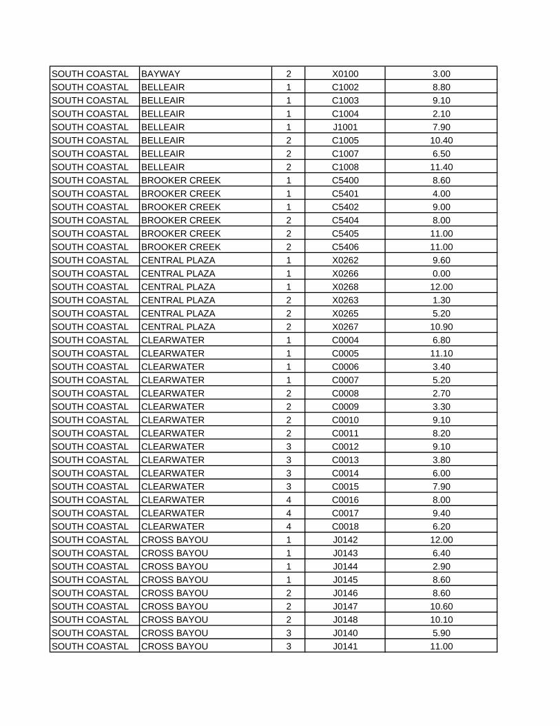
SOUTH COASTAL BAYWAY 2 X0100 3.00SOUTH COASTAL BELLEAIR 1 C1002 8.80SOUTH COASTAL BELLEAIR 1 C1003 9.10SOUTH COASTAL BELLEAIR 1 C1004 2.10SOUTH COASTAL BELLEAIR 1 J1001 7.90SOUTH COASTAL BELLEAIR 2 C1005 10.40SOUTH COASTAL BELLEAIR 2 C1007 6.50SOUTH COASTAL BELLEAIR 2 C1008 11.40SOUTH COASTAL BROOKER CREEK 1 C5400 8.60SOUTH COASTAL BROOKER CREEK 1 C5401 4.00SOUTH COASTAL BROOKER CREEK 1 C5402 9.00SOUTH COASTAL BROOKER CREEK 2 C5404 8.00SOUTH COASTAL BROOKER CREEK 2 C5405 11.00SOUTH COASTAL BROOKER CREEK 2 C5406 11.00SOUTH COASTAL CENTRAL PLAZA 1 X0262 9.60SOUTH COASTAL CENTRAL PLAZA 1 X0266 0.00SOUTH COASTAL CENTRAL PLAZA 1 X0268 12.00SOUTH COASTAL CENTRAL PLAZA 2 X0263 1.30SOUTH COASTAL CENTRAL PLAZA 2 X0265 5.20SOUTH COASTAL CENTRAL PLAZA 2 X0267 10.90SOUTH COASTAL CLEARWATER 1 C0004 6.80SOUTH COASTAL CLEARWATER 1 C0005 11.10SOUTH COASTAL CLEARWATER 1 C0006 3.40SOUTH COASTAL CLEARWATER 1 C0007 5.20SOUTH COASTAL CLEARWATER 2 C0008 2.70SOUTH COASTAL CLEARWATER 2 C0009 3.30SOUTH COASTAL CLEARWATER 2 C0010 9.10SOUTH COASTAL CLEARWATER 2 C0011 8.20SOUTH COASTAL CLEARWATER 3 C0012 9.10SOUTH COASTAL CLEARWATER 3 C0013 3.80SOUTH COASTAL CLEARWATER 3 C0014 6.00SOUTH COASTAL CLEARWATER 3 C0015 7.90SOUTH COASTAL CLEARWATER 4 C0016 8.00SOUTH COASTAL CLEARWATER 4 C0017 9.40SOUTH COASTAL CLEARWATER 4 C0018 6.20SOUTH COASTAL CROSS BAYOU 1 J0142 12.00SOUTH COASTAL CROSS BAYOU 1 J0143 6.40SOUTH COASTAL CROSS BAYOU 1 J0144 2.90SOUTH COASTAL CROSS BAYOU 1 J0145 8.60SOUTH COASTAL CROSS BAYOU 2 J0146 8.60SOUTH COASTAL CROSS BAYOU 2 J0147 10.60SOUTH COASTAL CROSS BAYOU 2 J0148 10.10SOUTH COASTAL CROSS BAYOU 3 J0140 5.90SOUTH COASTAL CROSS BAYOU 3 J0141 11.00
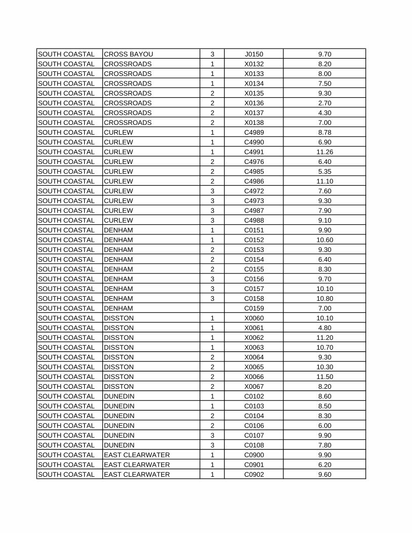
SOUTH COASTAL CROSS BAYOU 3 J0150 9.70SOUTH COASTAL CROSSROADS 1 X0132 8.20SOUTH COASTAL CROSSROADS 1 X0133 8.00SOUTH COASTAL CROSSROADS 1 X0134 7.50SOUTH COASTAL CROSSROADS 2 X0135 9.30SOUTH COASTAL CROSSROADS 2 X0136 2.70SOUTH COASTAL CROSSROADS 2 X0137 4.30SOUTH COASTAL CROSSROADS 2 X0138 7.00SOUTH COASTAL CURLEW 1 C4989 8.78SOUTH COASTAL CURLEW 1 C4990 6.90SOUTH COASTAL CURLEW 1 C4991 11.26SOUTH COASTAL CURLEW 2 C4976 6.40SOUTH COASTAL CURLEW 2 C4985 5.35SOUTH COASTAL CURLEW 2 C4986 11.10SOUTH COASTAL CURLEW 3 C4972 7.60SOUTH COASTAL CURLEW 3 C4973 9.30SOUTH COASTAL CURLEW 3 C4987 7.90SOUTH COASTAL CURLEW 3 C4988 9.10SOUTH COASTAL DENHAM 1 C0151 9.90SOUTH COASTAL DENHAM 1 C0152 10.60SOUTH COASTAL DENHAM 2 C0153 9.30SOUTH COASTAL DENHAM 2 C0154 6.40SOUTH COASTAL DENHAM 2 C0155 8.30SOUTH COASTAL DENHAM 3 C0156 9.70SOUTH COASTAL DENHAM 3 C0157 10.10SOUTH COASTAL DENHAM 3 C0158 10.80SOUTH COASTAL DENHAM C0159 7.00SOUTH COASTAL DISSTON 1 X0060 10.10SOUTH COASTAL DISSTON 1 X0061 4.80SOUTH COASTAL DISSTON 1 X0062 11.20SOUTH COASTAL DISSTON 1 X0063 10.70SOUTH COASTAL DISSTON 2 X0064 9.30SOUTH COASTAL DISSTON 2 X0065 10.30SOUTH COASTAL DISSTON 2 X0066 11.50SOUTH COASTAL DISSTON 2 X0067 8.20SOUTH COASTAL DUNEDIN 1 C0102 8.60SOUTH COASTAL DUNEDIN 1 C0103 8.50SOUTH COASTAL DUNEDIN 2 C0104 8.30SOUTH COASTAL DUNEDIN 2 C0106 6.00SOUTH COASTAL DUNEDIN 3 C0107 9.90SOUTH COASTAL DUNEDIN 3 C0108 7.80SOUTH COASTAL EAST CLEARWATER 1 C0900 9.90SOUTH COASTAL EAST CLEARWATER 1 C0901 6.20SOUTH COASTAL EAST CLEARWATER 1 C0902 9.60
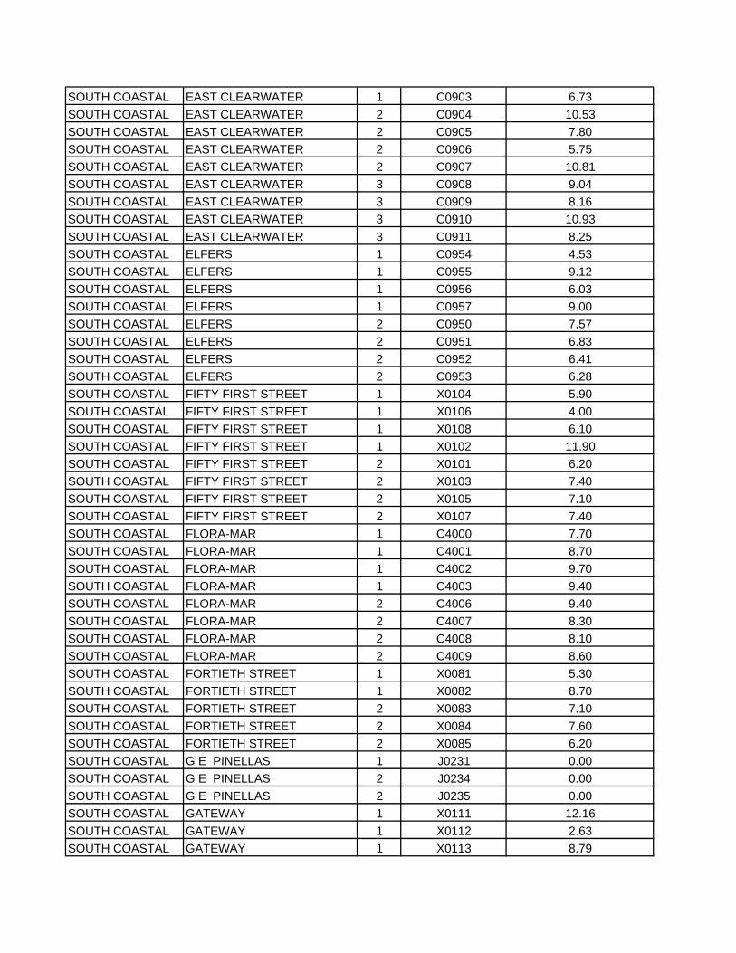
SOUTH COASTAL EAST CLEARWATER 1 C0903 6.73SOUTH COASTAL EAST CLEARWATER 2 C0904 10.53SOUTH COASTAL EAST CLEARWATER 2 C0905 7.80SOUTH COASTAL EAST CLEARWATER 2 C0906 5.75SOUTH COASTAL EAST CLEARWATER 2 C0907 10.81SOUTH COASTAL EAST CLEARWATER 3 C0908 9.04SOUTH COASTAL EAST CLEARWATER 3 C0909 8.16SOUTH COASTAL EAST CLEARWATER 3 C0910 10.93SOUTH COASTAL EAST CLEARWATER 3 C0911 8.25SOUTH COASTAL ELFERS 1 C0954 4.53SOUTH COASTAL ELFERS 1 C0955 9.12SOUTH COASTAL ELFERS 1 C0956 6.03SOUTH COASTAL ELFERS 1 C0957 9.00SOUTH COASTAL ELFERS 2 C0950 7.57SOUTH COASTAL ELFERS 2 C0951 6.83SOUTH COASTAL ELFERS 2 C0952 6.41SOUTH COASTAL ELFERS 2 C0953 6.28SOUTH COASTAL FIFTY FIRST STREET 1 X0104 5.90SOUTH COASTAL FIFTY FIRST STREET 1 X0106 4.00SOUTH COASTAL FIFTY FIRST STREET 1 X0108 6.10SOUTH COASTAL FIFTY FIRST STREET 1 X0102 11.90SOUTH COASTAL FIFTY FIRST STREET 2 X0101 6.20SOUTH COASTAL FIFTY FIRST STREET 2 X0103 7.40SOUTH COASTAL FIFTY FIRST STREET 2 X0105 7.10SOUTH COASTAL FIFTY FIRST STREET 2 X0107 7.40SOUTH COASTAL FLORA-MAR 1 C4000 7.70SOUTH COASTAL FLORA-MAR 1 C4001 8.70SOUTH COASTAL FLORA-MAR 1 C4002 9.70SOUTH COASTAL FLORA-MAR 1 C4003 9.40SOUTH COASTAL FLORA-MAR 2 C4006 9.40SOUTH COASTAL FLORA-MAR 2 C4007 8.30SOUTH COASTAL FLORA-MAR 2 C4008 8.10SOUTH COASTAL FLORA-MAR 2 C4009 8.60SOUTH COASTAL FORTIETH STREET 1 X0081 5.30SOUTH COASTAL FORTIETH STREET 1 X0082 8.70SOUTH COASTAL FORTIETH STREET 2 X0083 7.10SOUTH COASTAL FORTIETH STREET 2 X0084 7.60SOUTH COASTAL FORTIETH STREET 2 X0085 6.20SOUTH COASTAL G E PINELLAS 1 J0231 0.00SOUTH COASTAL G E PINELLAS 2 J0234 0.00SOUTH COASTAL G E PINELLAS 2 J0235 0.00SOUTH COASTAL GATEWAY 1 X0111 12.16SOUTH COASTAL GATEWAY 1 X0112 2.63SOUTH COASTAL GATEWAY 1 X0113 8.79
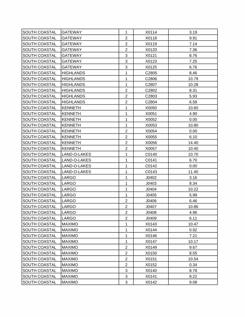
SOUTH COASTAL GATEWAY 1 X0114 3.19SOUTH COASTAL GATEWAY 2 X0118 9.91SOUTH COASTAL GATEWAY 2 X0119 7.14SOUTH COASTAL GATEWAY 2 X0120 7.36SOUTH COASTAL GATEWAY 3 X0121 8.76SOUTH COASTAL GATEWAY 3 X0123 7.25SOUTH COASTAL GATEWAY 3 X0125 6.76SOUTH COASTAL HIGHLANDS 1 C2805 8.46SOUTH COASTAL HIGHLANDS 1 C2806 10.79SOUTH COASTAL HIGHLANDS 1 C2807 10.28SOUTH COASTAL HIGHLANDS 2 C2802 8.31SOUTH COASTAL HIGHLANDS 2 C2803 5.93SOUTH COASTAL HIGHLANDS 2 C2804 6.58SOUTH COASTAL KENNETH 1 X0050 10.60SOUTH COASTAL KENNETH 1 X0051 4.90SOUTH COASTAL KENNETH 1 X0052 0.00SOUTH COASTAL KENNETH 1 X0053 10.80SOUTH COASTAL KENNETH 2 X0054 0.00SOUTH COASTAL KENNETH 2 X0055 6.10SOUTH COASTAL KENNETH 2 X0056 14.40SOUTH COASTAL KENNETH 2 X0057 10.40SOUTH COASTAL LAND-O-LAKES 1 C0140 10.70SOUTH COASTAL LAND-O-LAKES 1 C0141 6.70SOUTH COASTAL LAND-O-LAKES 1 C0142 0.00SOUTH COASTAL LAND-O-LAKES 1 C0143 11.40SOUTH COASTAL LARGO 1 J0402 3.16SOUTH COASTAL LARGO 1 J0403 8.34SOUTH COASTAL LARGO 1 J0404 10.22SOUTH COASTAL LARGO 1 J0405 5.99SOUTH COASTAL LARGO 2 J0406 6.46SOUTH COASTAL LARGO 2 J0407 10.86SOUTH COASTAL LARGO 2 J0408 4.96SOUTH COASTAL LARGO 2 J0409 6.11SOUTH COASTAL MAXIMO 1 X0143 10.47SOUTH COASTAL MAXIMO 1 X0144 0.92SOUTH COASTAL MAXIMO 1 X0146 7.21SOUTH COASTAL MAXIMO 1 X0147 10.17SOUTH COASTAL MAXIMO 2 X0149 9.67SOUTH COASTAL MAXIMO 2 X0150 8.55SOUTH COASTAL MAXIMO 2 X0151 10.54SOUTH COASTAL MAXIMO 2 X0152 0.34SOUTH COASTAL MAXIMO 3 X0140 8.78SOUTH COASTAL MAXIMO 3 X0141 8.22SOUTH COASTAL MAXIMO 3 X0142 9.08
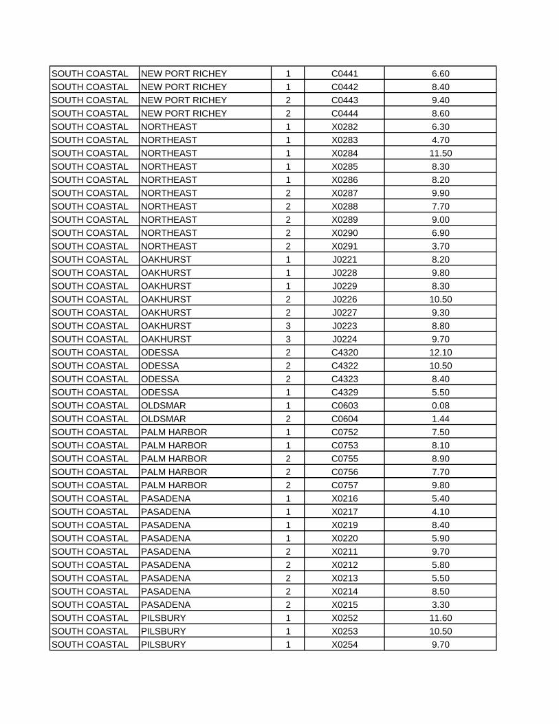
SOUTH COASTAL NEW PORT RICHEY 1 C0441 6.60SOUTH COASTAL NEW PORT RICHEY 1 C0442 8.40SOUTH COASTAL NEW PORT RICHEY 2 C0443 9.40SOUTH COASTAL NEW PORT RICHEY 2 C0444 8.60SOUTH COASTAL NORTHEAST 1 X0282 6.30SOUTH COASTAL NORTHEAST 1 X0283 4.70SOUTH COASTAL NORTHEAST 1 X0284 11.50SOUTH COASTAL NORTHEAST 1 X0285 8.30SOUTH COASTAL NORTHEAST 1 X0286 8.20SOUTH COASTAL NORTHEAST 2 X0287 9.90SOUTH COASTAL NORTHEAST 2 X0288 7.70SOUTH COASTAL NORTHEAST 2 X0289 9.00SOUTH COASTAL NORTHEAST 2 X0290 6.90SOUTH COASTAL NORTHEAST 2 X0291 3.70SOUTH COASTAL OAKHURST 1 J0221 8.20SOUTH COASTAL OAKHURST 1 J0228 9.80SOUTH COASTAL OAKHURST 1 J0229 8.30SOUTH COASTAL OAKHURST 2 J0226 10.50SOUTH COASTAL OAKHURST 2 J0227 9.30SOUTH COASTAL OAKHURST 3 J0223 8.80SOUTH COASTAL OAKHURST 3 J0224 9.70SOUTH COASTAL ODESSA 2 C4320 12.10SOUTH COASTAL ODESSA 2 C4322 10.50SOUTH COASTAL ODESSA 2 C4323 8.40SOUTH COASTAL ODESSA 1 C4329 5.50SOUTH COASTAL OLDSMAR 1 C0603 0.08SOUTH COASTAL OLDSMAR 2 C0604 1.44SOUTH COASTAL PALM HARBOR 1 C0752 7.50SOUTH COASTAL PALM HARBOR 1 C0753 8.10SOUTH COASTAL PALM HARBOR 2 C0755 8.90SOUTH COASTAL PALM HARBOR 2 C0756 7.70SOUTH COASTAL PALM HARBOR 2 C0757 9.80SOUTH COASTAL PASADENA 1 X0216 5.40SOUTH COASTAL PASADENA 1 X0217 4.10SOUTH COASTAL PASADENA 1 X0219 8.40SOUTH COASTAL PASADENA 1 X0220 5.90SOUTH COASTAL PASADENA 2 X0211 9.70SOUTH COASTAL PASADENA 2 X0212 5.80SOUTH COASTAL PASADENA 2 X0213 5.50SOUTH COASTAL PASADENA 2 X0214 8.50SOUTH COASTAL PASADENA 2 X0215 3.30SOUTH COASTAL PILSBURY 1 X0252 11.60SOUTH COASTAL PILSBURY 1 X0253 10.50SOUTH COASTAL PILSBURY 1 X0254 9.70
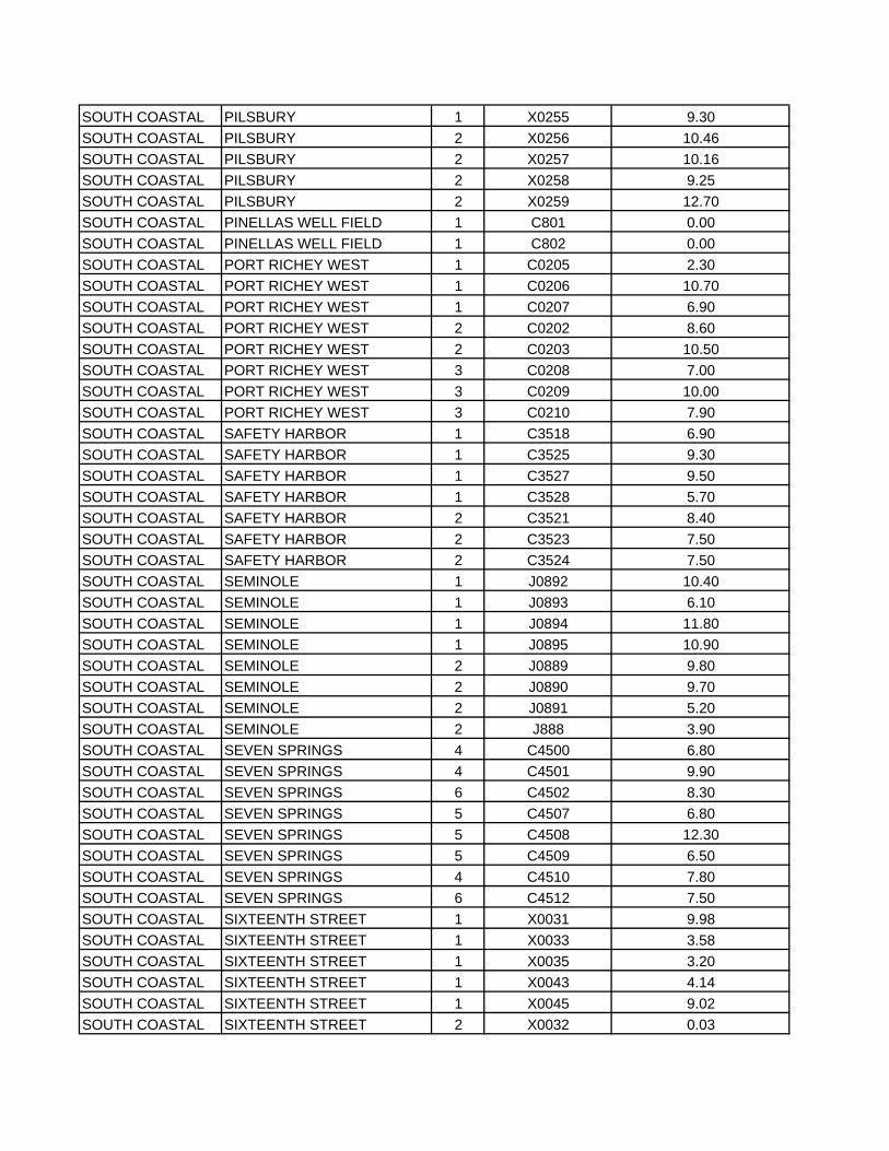
SOUTH COASTAL PILSBURY 1 X0255 9.30SOUTH COASTAL PILSBURY 2 X0256 10.46SOUTH COASTAL PILSBURY 2 X0257 10.16SOUTH COASTAL PILSBURY 2 X0258 9.25SOUTH COASTAL PILSBURY 2 X0259 12.70SOUTH COASTAL PINELLAS WELL FIELD 1 C801 0.00SOUTH COASTAL PINELLAS WELL FIELD 1 C802 0.00SOUTH COASTAL PORT RICHEY WEST 1 C0205 2.30SOUTH COASTAL PORT RICHEY WEST 1 C0206 10.70SOUTH COASTAL PORT RICHEY WEST 1 C0207 6.90SOUTH COASTAL PORT RICHEY WEST 2 C0202 8.60SOUTH COASTAL PORT RICHEY WEST 2 C0203 10.50SOUTH COASTAL PORT RICHEY WEST 3 C0208 7.00SOUTH COASTAL PORT RICHEY WEST 3 C0209 10.00SOUTH COASTAL PORT RICHEY WEST 3 C0210 7.90SOUTH COASTAL SAFETY HARBOR 1 C3518 6.90SOUTH COASTAL SAFETY HARBOR 1 C3525 9.30SOUTH COASTAL SAFETY HARBOR 1 C3527 9.50SOUTH COASTAL SAFETY HARBOR 1 C3528 5.70SOUTH COASTAL SAFETY HARBOR 2 C3521 8.40SOUTH COASTAL SAFETY HARBOR 2 C3523 7.50SOUTH COASTAL SAFETY HARBOR 2 C3524 7.50SOUTH COASTAL SEMINOLE 1 J0892 10.40SOUTH COASTAL SEMINOLE 1 J0893 6.10SOUTH COASTAL SEMINOLE 1 J0894 11.80SOUTH COASTAL SEMINOLE 1 J0895 10.90SOUTH COASTAL SEMINOLE 2 J0889 9.80SOUTH COASTAL SEMINOLE 2 J0890 9.70SOUTH COASTAL SEMINOLE 2 J0891 5.20SOUTH COASTAL SEMINOLE 2 J888 3.90SOUTH COASTAL SEVEN SPRINGS 4 C4500 6.80SOUTH COASTAL SEVEN SPRINGS 4 C4501 9.90SOUTH COASTAL SEVEN SPRINGS 6 C4502 8.30SOUTH COASTAL SEVEN SPRINGS 5 C4507 6.80SOUTH COASTAL SEVEN SPRINGS 5 C4508 12.30SOUTH COASTAL SEVEN SPRINGS 5 C4509 6.50SOUTH COASTAL SEVEN SPRINGS 4 C4510 7.80SOUTH COASTAL SEVEN SPRINGS 6 C4512 7.50SOUTH COASTAL SIXTEENTH STREET 1 X0031 9.98SOUTH COASTAL SIXTEENTH STREET 1 X0033 3.58SOUTH COASTAL SIXTEENTH STREET 1 X0035 3.20SOUTH COASTAL SIXTEENTH STREET 1 X0043 4.14SOUTH COASTAL SIXTEENTH STREET 1 X0045 9.02SOUTH COASTAL SIXTEENTH STREET 2 X0032 0.03
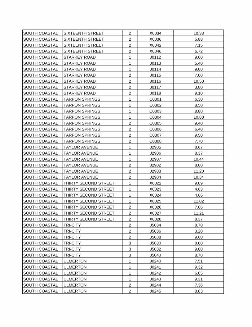
SOUTH COASTAL SIXTEENTH STREET 2 X0034 10.33SOUTH COASTAL SIXTEENTH STREET 2 X0036 5.88SOUTH COASTAL SIXTEENTH STREET 2 X0042 7.15SOUTH COASTAL SIXTEENTH STREET 2 X0046 6.72SOUTH COASTAL STARKEY ROAD 1 J0112 9.00SOUTH COASTAL STARKEY ROAD 1 J0113 5.40SOUTH COASTAL STARKEY ROAD 1 J0114 9.00SOUTH COASTAL STARKEY ROAD 2 J0115 7.00SOUTH COASTAL STARKEY ROAD 2 J0116 10.50SOUTH COASTAL STARKEY ROAD 2 J0117 3.80SOUTH COASTAL STARKEY ROAD 2 J0118 9.10SOUTH COASTAL TARPON SPRINGS 1 C0301 6.30SOUTH COASTAL TARPON SPRINGS 1 C0302 8.50SOUTH COASTAL TARPON SPRINGS 1 C0303 8.80SOUTH COASTAL TARPON SPRINGS 1 C0304 10.80SOUTH COASTAL TARPON SPRINGS 2 C0305 9.40SOUTH COASTAL TARPON SPRINGS 2 C0306 6.40SOUTH COASTAL TARPON SPRINGS 2 C0307 9.50SOUTH COASTAL TARPON SPRINGS 2 C0308 7.70SOUTH COASTAL TAYLOR AVENUE 1 J2905 8.67SOUTH COASTAL TAYLOR AVENUE 1 J2906 8.37SOUTH COASTAL TAYLOR AVENUE 1 J2907 10.44SOUTH COASTAL TAYLOR AVENUE 2 J2902 8.00SOUTH COASTAL TAYLOR AVENUE 2 J2903 11.20SOUTH COASTAL TAYLOR AVENUE 2 J2904 10.34SOUTH COASTAL THIRTY SECOND STREET 1 X0022 9.09SOUTH COASTAL THIRTY SECOND STREET 1 X0023 4.63SOUTH COASTAL THIRTY SECOND STREET 1 X0024 4.66SOUTH COASTAL THIRTY SECOND STREET 1 X0025 11.02SOUTH COASTAL THIRTY SECOND STREET 2 X0026 7.06SOUTH COASTAL THIRTY SECOND STREET 2 X0027 11.21SOUTH COASTAL THIRTY SECOND STREET 2 X0028 8.37SOUTH COASTAL TRI-CITY 2 J5034 8.70SOUTH COASTAL TRI-CITY 2 J5036 3.20SOUTH COASTAL TRI-CITY 2 J5038 9.60SOUTH COASTAL TRI-CITY 3 J5030 8.00SOUTH COASTAL TRI-CITY 3 J5032 9.00SOUTH COASTAL TRI-CITY 3 J5040 8.70SOUTH COASTAL ULMERTON 1 J0240 7.51SOUTH COASTAL ULMERTON 1 J0241 9.32SOUTH COASTAL ULMERTON 1 J0242 6.05SOUTH COASTAL ULMERTON 1 J0243 9.31SOUTH COASTAL ULMERTON 2 J0244 7.36SOUTH COASTAL ULMERTON 2 J0245 8.83
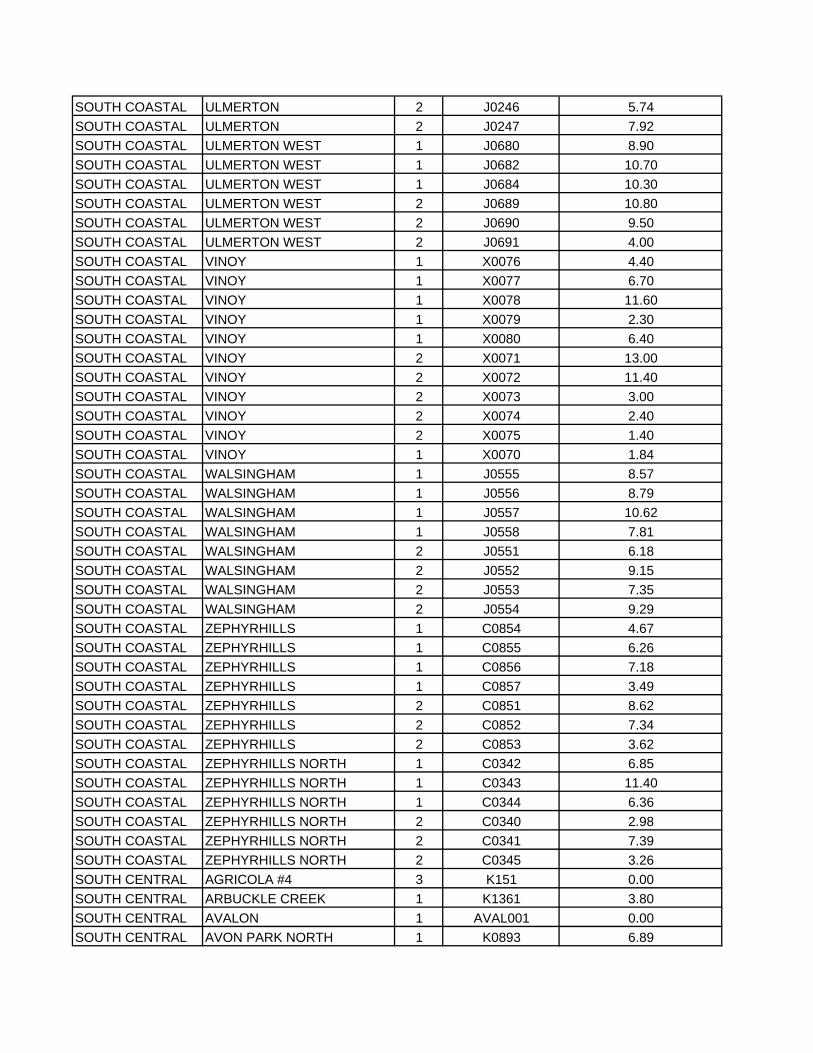
SOUTH COASTAL ULMERTON 2 J0246 5.74SOUTH COASTAL ULMERTON 2 J0247 7.92SOUTH COASTAL ULMERTON WEST 1 J0680 8.90SOUTH COASTAL ULMERTON WEST 1 J0682 10.70SOUTH COASTAL ULMERTON WEST 1 J0684 10.30SOUTH COASTAL ULMERTON WEST 2 J0689 10.80SOUTH COASTAL ULMERTON WEST 2 J0690 9.50SOUTH COASTAL ULMERTON WEST 2 J0691 4.00SOUTH COASTAL VINOY 1 X0076 4.40SOUTH COASTAL VINOY 1 X0077 6.70SOUTH COASTAL VINOY 1 X0078 11.60SOUTH COASTAL VINOY 1 X0079 2.30SOUTH COASTAL VINOY 1 X0080 6.40SOUTH COASTAL VINOY 2 X0071 13.00SOUTH COASTAL VINOY 2 X0072 11.40SOUTH COASTAL VINOY 2 X0073 3.00SOUTH COASTAL VINOY 2 X0074 2.40SOUTH COASTAL VINOY 2 X0075 1.40SOUTH COASTAL VINOY 1 X0070 1.84SOUTH COASTAL WALSINGHAM 1 J0555 8.57SOUTH COASTAL WALSINGHAM 1 J0556 8.79SOUTH COASTAL WALSINGHAM 1 J0557 10.62SOUTH COASTAL WALSINGHAM 1 J0558 7.81SOUTH COASTAL WALSINGHAM 2 J0551 6.18SOUTH COASTAL WALSINGHAM 2 J0552 9.15SOUTH COASTAL WALSINGHAM 2 J0553 7.35SOUTH COASTAL WALSINGHAM 2 J0554 9.29SOUTH COASTAL ZEPHYRHILLS 1 C0854 4.67SOUTH COASTAL ZEPHYRHILLS 1 C0855 6.26SOUTH COASTAL ZEPHYRHILLS 1 C0856 7.18SOUTH COASTAL ZEPHYRHILLS 1 C0857 3.49SOUTH COASTAL ZEPHYRHILLS 2 C0851 8.62SOUTH COASTAL ZEPHYRHILLS 2 C0852 7.34SOUTH COASTAL ZEPHYRHILLS 2 C0853 3.62SOUTH COASTAL ZEPHYRHILLS NORTH 1 C0342 6.85SOUTH COASTAL ZEPHYRHILLS NORTH 1 C0343 11.40SOUTH COASTAL ZEPHYRHILLS NORTH 1 C0344 6.36SOUTH COASTAL ZEPHYRHILLS NORTH 2 C0340 2.98SOUTH COASTAL ZEPHYRHILLS NORTH 2 C0341 7.39SOUTH COASTAL ZEPHYRHILLS NORTH 2 C0345 3.26SOUTH CENTRAL AGRICOLA #4 3 K151 0.00SOUTH CENTRAL ARBUCKLE CREEK 1 K1361 3.80SOUTH CENTRAL AVALON 1 AVAL001 0.00SOUTH CENTRAL AVON PARK NORTH 1 K0893 6.89
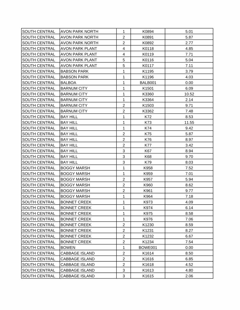
SOUTH CENTRAL AVON PARK NORTH 1 K0894 5.01SOUTH CENTRAL AVON PARK NORTH 2 K0891 5.87SOUTH CENTRAL AVON PARK NORTH 2 K0892 2.77SOUTH CENTRAL AVON PARK PLANT 4 K0118 4.85SOUTH CENTRAL AVON PARK PLANT 4 K0119 7.71SOUTH CENTRAL AVON PARK PLANT 5 K0116 5.04SOUTH CENTRAL AVON PARK PLANT 5 K0117 7.11SOUTH CENTRAL BABSON PARK 1 K1195 3.79SOUTH CENTRAL BABSON PARK 1 K1196 4.03SOUTH CENTRAL BALBOA 1 BALB001 0.00SOUTH CENTRAL BARNUM CITY 1 K1501 6.09SOUTH CENTRAL BARNUM CITY 1 K3360 10.52SOUTH CENTRAL BARNUM CITY 1 K3364 2.14SOUTH CENTRAL BARNUM CITY 2 K1503 9.71SOUTH CENTRAL BARNUM CITY 2 K3362 7.48SOUTH CENTRAL BAY HILL 1 K72 8.53SOUTH CENTRAL BAY HILL 1 K73 11.55SOUTH CENTRAL BAY HILL 1 K74 9.42SOUTH CENTRAL BAY HILL 2 K75 5.87SOUTH CENTRAL BAY HILL 2 K76 8.97SOUTH CENTRAL BAY HILL 2 K77 3.42SOUTH CENTRAL BAY HILL 3 K67 8.94SOUTH CENTRAL BAY HILL 3 K68 9.70SOUTH CENTRAL BAY HILL 3 K79 8.03SOUTH CENTRAL BOGGY MARSH 1 K958 7.52SOUTH CENTRAL BOGGY MARSH 1 K959 7.01SOUTH CENTRAL BOGGY MARSH 2 K957 5.94SOUTH CENTRAL BOGGY MARSH 2 K960 8.62SOUTH CENTRAL BOGGY MARSH 2 K961 9.77SOUTH CENTRAL BOGGY MARSH 1 K964 7.18SOUTH CENTRAL BONNET CREEK 1 K973 4.09SOUTH CENTRAL BONNET CREEK 1 K974 6.14SOUTH CENTRAL BONNET CREEK 1 K975 8.58SOUTH CENTRAL BONNET CREEK 1 K976 7.06SOUTH CENTRAL BONNET CREEK 2 K1230 8.59SOUTH CENTRAL BONNET CREEK 2 K1231 8.27SOUTH CENTRAL BONNET CREEK 2 K1232 6.67SOUTH CENTRAL BONNET CREEK 2 K1234 7.54SOUTH CENTRAL BOWEN 1 BOWE001 0.00SOUTH CENTRAL CABBAGE ISLAND 2 K1614 8.50SOUTH CENTRAL CABBAGE ISLAND 2 K1616 6.85SOUTH CENTRAL CABBAGE ISLAND 2 K1618 4.52SOUTH CENTRAL CABBAGE ISLAND 3 K1613 4.80SOUTH CENTRAL CABBAGE ISLAND 3 K1615 2.06
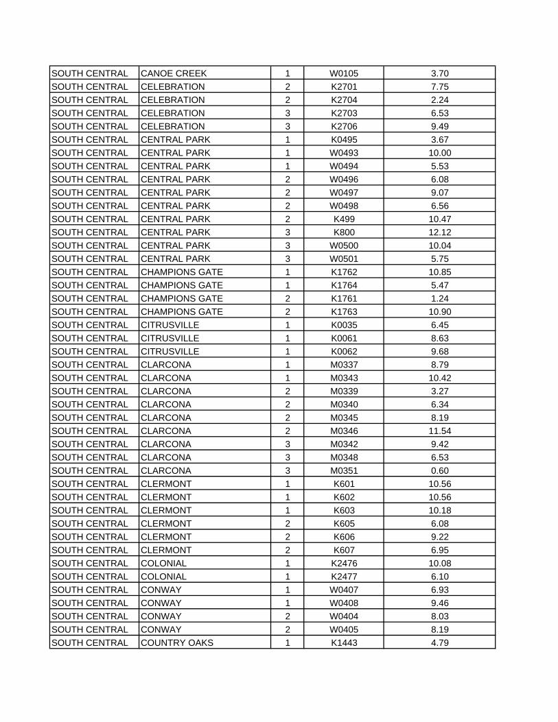
SOUTH CENTRAL CANOE CREEK 1 W0105 3.70SOUTH CENTRAL CELEBRATION 2 K2701 7.75SOUTH CENTRAL CELEBRATION 2 K2704 2.24SOUTH CENTRAL CELEBRATION 3 K2703 6.53SOUTH CENTRAL CELEBRATION 3 K2706 9.49SOUTH CENTRAL CENTRAL PARK 1 K0495 3.67SOUTH CENTRAL CENTRAL PARK 1 W0493 10.00SOUTH CENTRAL CENTRAL PARK 1 W0494 5.53SOUTH CENTRAL CENTRAL PARK 2 W0496 6.08SOUTH CENTRAL CENTRAL PARK 2 W0497 9.07SOUTH CENTRAL CENTRAL PARK 2 W0498 6.56SOUTH CENTRAL CENTRAL PARK 2 K499 10.47SOUTH CENTRAL CENTRAL PARK 3 K800 12.12SOUTH CENTRAL CENTRAL PARK 3 W0500 10.04SOUTH CENTRAL CENTRAL PARK 3 W0501 5.75SOUTH CENTRAL CHAMPIONS GATE 1 K1762 10.85SOUTH CENTRAL CHAMPIONS GATE 1 K1764 5.47SOUTH CENTRAL CHAMPIONS GATE 2 K1761 1.24SOUTH CENTRAL CHAMPIONS GATE 2 K1763 10.90SOUTH CENTRAL CITRUSVILLE 1 K0035 6.45SOUTH CENTRAL CITRUSVILLE 1 K0061 8.63SOUTH CENTRAL CITRUSVILLE 1 K0062 9.68SOUTH CENTRAL CLARCONA 1 M0337 8.79SOUTH CENTRAL CLARCONA 1 M0343 10.42SOUTH CENTRAL CLARCONA 2 M0339 3.27SOUTH CENTRAL CLARCONA 2 M0340 6.34SOUTH CENTRAL CLARCONA 2 M0345 8.19SOUTH CENTRAL CLARCONA 2 M0346 11.54SOUTH CENTRAL CLARCONA 3 M0342 9.42SOUTH CENTRAL CLARCONA 3 M0348 6.53SOUTH CENTRAL CLARCONA 3 M0351 0.60SOUTH CENTRAL CLERMONT 1 K601 10.56SOUTH CENTRAL CLERMONT 1 K602 10.56SOUTH CENTRAL CLERMONT 1 K603 10.18SOUTH CENTRAL CLERMONT 2 K605 6.08SOUTH CENTRAL CLERMONT 2 K606 9.22SOUTH CENTRAL CLERMONT 2 K607 6.95SOUTH CENTRAL COLONIAL 1 K2476 10.08SOUTH CENTRAL COLONIAL 1 K2477 6.10SOUTH CENTRAL CONWAY 1 W0407 6.93SOUTH CENTRAL CONWAY 1 W0408 9.46SOUTH CENTRAL CONWAY 2 W0404 8.03SOUTH CENTRAL CONWAY 2 W0405 8.19SOUTH CENTRAL COUNTRY OAKS 1 K1443 4.79
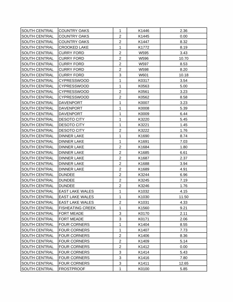
SOUTH CENTRAL COUNTRY OAKS 1 K1446 2.36SOUTH CENTRAL COUNTRY OAKS 2 K1445 0.00SOUTH CENTRAL COUNTRY OAKS 2 K1447 8.32SOUTH CENTRAL CROOKED LAKE 1 K1772 8.19SOUTH CENTRAL CURRY FORD 2 W595 3.43SOUTH CENTRAL CURRY FORD 2 W596 10.70SOUTH CENTRAL CURRY FORD 2 W597 8.53SOUTH CENTRAL CURRY FORD 2 W598 8.20SOUTH CENTRAL CURRY FORD 3 W601 10.18SOUTH CENTRAL CYPRESSWOOD 1 K0317 3.54SOUTH CENTRAL CYPRESSWOOD 1 K0563 5.00SOUTH CENTRAL CYPRESSWOOD 2 K0561 3.23SOUTH CENTRAL CYPRESSWOOD 2 K0562 8.58SOUTH CENTRAL DAVENPORT 1 K0007 3.23SOUTH CENTRAL DAVENPORT 1 K0008 5.39SOUTH CENTRAL DAVENPORT 1 K0009 6.44SOUTH CENTRAL DESOTO CITY 1 K3220 5.45SOUTH CENTRAL DESOTO CITY 1 K3221 1.45SOUTH CENTRAL DESOTO CITY 2 K3222 1.76SOUTH CENTRAL DINNER LAKE 1 K1690 8.74SOUTH CENTRAL DINNER LAKE 1 K1691 7.03SOUTH CENTRAL DINNER LAKE 2 K1684 1.80SOUTH CENTRAL DINNER LAKE 2 K1685 6.61SOUTH CENTRAL DINNER LAKE 2 K1687 2.37SOUTH CENTRAL DINNER LAKE 2 K1688 3.94SOUTH CENTRAL DINNER LAKE 2 K1689 4.91SOUTH CENTRAL DUNDEE 2 K3244 6.96SOUTH CENTRAL DUNDEE 2 K3245 7.19SOUTH CENTRAL DUNDEE 2 K3246 1.76SOUTH CENTRAL EAST LAKE WALES 1 K1032 4.15SOUTH CENTRAL EAST LAKE WALES 1 K1030 11.50SOUTH CENTRAL EAST LAKE WALES 2 K1031 4.33SOUTH CENTRAL FISHEATING CREEK 1 K1560 9.21SOUTH CENTRAL FORT MEADE 3 K0170 2.11SOUTH CENTRAL FORT MEADE 3 K0171 2.06SOUTH CENTRAL FOUR CORNERS 1 K1404 8.55SOUTH CENTRAL FOUR CORNERS 1 K1407 7.73SOUTH CENTRAL FOUR CORNERS 2 K1406 8.36SOUTH CENTRAL FOUR CORNERS 2 K1409 5.14SOUTH CENTRAL FOUR CORNERS 2 K1412 0.00SOUTH CENTRAL FOUR CORNERS 3 K1414 5.43SOUTH CENTRAL FOUR CORNERS 3 K1416 7.80SOUTH CENTRAL FOUR CORNERS 3 K1411 12.65SOUTH CENTRAL FROSTPROOF 1 K0100 5.85
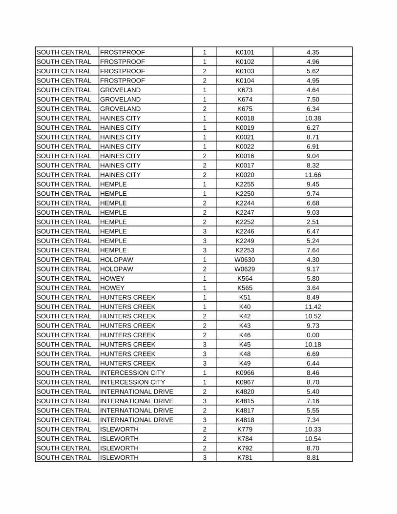
SOUTH CENTRAL FROSTPROOF 1 K0101 4.35SOUTH CENTRAL FROSTPROOF 1 K0102 4.96SOUTH CENTRAL FROSTPROOF 2 K0103 5.62SOUTH CENTRAL FROSTPROOF 2 K0104 4.95SOUTH CENTRAL GROVELAND 1 K673 4.64SOUTH CENTRAL GROVELAND 1 K674 7.50SOUTH CENTRAL GROVELAND 2 K675 6.34SOUTH CENTRAL HAINES CITY 1 K0018 10.38SOUTH CENTRAL HAINES CITY 1 K0019 6.27SOUTH CENTRAL HAINES CITY 1 K0021 8.71SOUTH CENTRAL HAINES CITY 1 K0022 6.91SOUTH CENTRAL HAINES CITY 2 K0016 9.04SOUTH CENTRAL HAINES CITY 2 K0017 8.32SOUTH CENTRAL HAINES CITY 2 K0020 11.66SOUTH CENTRAL HEMPLE 1 K2255 9.45SOUTH CENTRAL HEMPLE 1 K2250 9.74SOUTH CENTRAL HEMPLE 2 K2244 6.68SOUTH CENTRAL HEMPLE 2 K2247 9.03SOUTH CENTRAL HEMPLE 2 K2252 2.51SOUTH CENTRAL HEMPLE 3 K2246 6.47SOUTH CENTRAL HEMPLE 3 K2249 5.24SOUTH CENTRAL HEMPLE 3 K2253 7.64SOUTH CENTRAL HOLOPAW 1 W0630 4.30SOUTH CENTRAL HOLOPAW 2 W0629 9.17SOUTH CENTRAL HOWEY 1 K564 5.80SOUTH CENTRAL HOWEY 1 K565 3.64SOUTH CENTRAL HUNTERS CREEK 1 K51 8.49SOUTH CENTRAL HUNTERS CREEK 1 K40 11.42SOUTH CENTRAL HUNTERS CREEK 2 K42 10.52SOUTH CENTRAL HUNTERS CREEK 2 K43 9.73SOUTH CENTRAL HUNTERS CREEK 2 K46 0.00SOUTH CENTRAL HUNTERS CREEK 3 K45 10.18SOUTH CENTRAL HUNTERS CREEK 3 K48 6.69SOUTH CENTRAL HUNTERS CREEK 3 K49 6.44SOUTH CENTRAL INTERCESSION CITY 1 K0966 8.46SOUTH CENTRAL INTERCESSION CITY 1 K0967 8.70SOUTH CENTRAL INTERNATIONAL DRIVE 2 K4820 5.40SOUTH CENTRAL INTERNATIONAL DRIVE 3 K4815 7.16SOUTH CENTRAL INTERNATIONAL DRIVE 2 K4817 5.55SOUTH CENTRAL INTERNATIONAL DRIVE 3 K4818 7.34SOUTH CENTRAL ISLEWORTH 2 K779 10.33SOUTH CENTRAL ISLEWORTH 2 K784 10.54SOUTH CENTRAL ISLEWORTH 2 K792 8.70SOUTH CENTRAL ISLEWORTH 3 K781 8.81
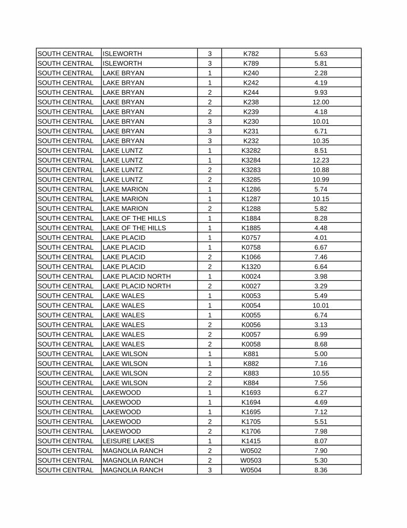
SOUTH CENTRAL ISLEWORTH 3 K782 5.63SOUTH CENTRAL ISLEWORTH 3 K789 5.81SOUTH CENTRAL LAKE BRYAN 1 K240 2.28SOUTH CENTRAL LAKE BRYAN 1 K242 4.19SOUTH CENTRAL LAKE BRYAN 2 K244 9.93SOUTH CENTRAL LAKE BRYAN 2 K238 12.00SOUTH CENTRAL LAKE BRYAN 2 K239 4.18SOUTH CENTRAL LAKE BRYAN 3 K230 10.01SOUTH CENTRAL LAKE BRYAN 3 K231 6.71SOUTH CENTRAL LAKE BRYAN 3 K232 10.35SOUTH CENTRAL LAKE LUNTZ 1 K3282 8.51SOUTH CENTRAL LAKE LUNTZ 1 K3284 12.23SOUTH CENTRAL LAKE LUNTZ 2 K3283 10.88SOUTH CENTRAL LAKE LUNTZ 2 K3285 10.99SOUTH CENTRAL LAKE MARION 1 K1286 5.74SOUTH CENTRAL LAKE MARION 1 K1287 10.15SOUTH CENTRAL LAKE MARION 2 K1288 5.82SOUTH CENTRAL LAKE OF THE HILLS 1 K1884 8.28SOUTH CENTRAL LAKE OF THE HILLS 1 K1885 4.48SOUTH CENTRAL LAKE PLACID 1 K0757 4.01SOUTH CENTRAL LAKE PLACID 1 K0758 6.67SOUTH CENTRAL LAKE PLACID 2 K1066 7.46SOUTH CENTRAL LAKE PLACID 2 K1320 6.64SOUTH CENTRAL LAKE PLACID NORTH 1 K0024 3.98SOUTH CENTRAL LAKE PLACID NORTH 2 K0027 3.29SOUTH CENTRAL LAKE WALES 1 K0053 5.49SOUTH CENTRAL LAKE WALES 1 K0054 10.01SOUTH CENTRAL LAKE WALES 1 K0055 6.74SOUTH CENTRAL LAKE WALES 2 K0056 3.13SOUTH CENTRAL LAKE WALES 2 K0057 6.99SOUTH CENTRAL LAKE WALES 2 K0058 8.68SOUTH CENTRAL LAKE WILSON 1 K881 5.00SOUTH CENTRAL LAKE WILSON 1 K882 7.16SOUTH CENTRAL LAKE WILSON 2 K883 10.55SOUTH CENTRAL LAKE WILSON 2 K884 7.56SOUTH CENTRAL LAKEWOOD 1 K1693 6.27SOUTH CENTRAL LAKEWOOD 1 K1694 4.69SOUTH CENTRAL LAKEWOOD 1 K1695 7.12SOUTH CENTRAL LAKEWOOD 2 K1705 5.51SOUTH CENTRAL LAKEWOOD 2 K1706 7.98SOUTH CENTRAL LEISURE LAKES 1 K1415 8.07SOUTH CENTRAL MAGNOLIA RANCH 2 W0502 7.90SOUTH CENTRAL MAGNOLIA RANCH 2 W0503 5.30SOUTH CENTRAL MAGNOLIA RANCH 3 W0504 8.36
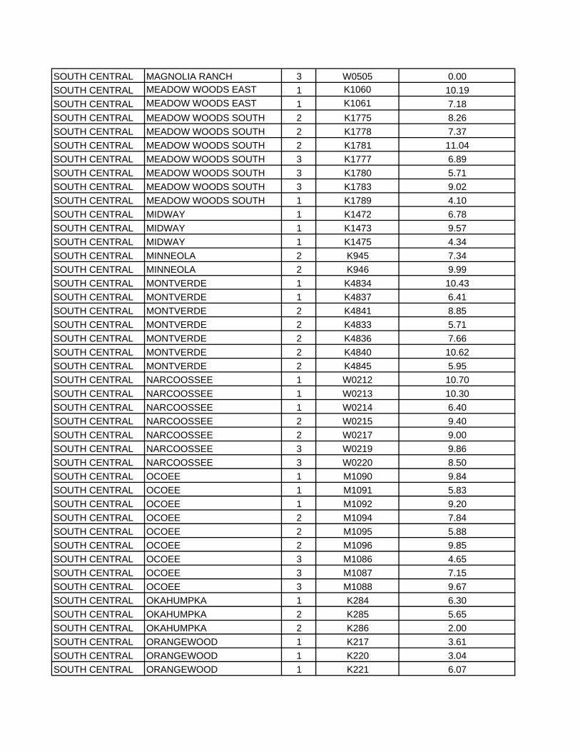
SOUTH CENTRAL MAGNOLIA RANCH 3 W0505 0.00SOUTH CENTRAL MEADOW WOODS EAST 1 K1060 10.19SOUTH CENTRAL MEADOW WOODS EAST 1 K1061 7.18SOUTH CENTRAL MEADOW WOODS SOUTH 2 K1775 8.26SOUTH CENTRAL MEADOW WOODS SOUTH 2 K1778 7.37SOUTH CENTRAL MEADOW WOODS SOUTH 2 K1781 11.04SOUTH CENTRAL MEADOW WOODS SOUTH 3 K1777 6.89SOUTH CENTRAL MEADOW WOODS SOUTH 3 K1780 5.71SOUTH CENTRAL MEADOW WOODS SOUTH 3 K1783 9.02SOUTH CENTRAL MEADOW WOODS SOUTH 1 K1789 4.10SOUTH CENTRAL MIDWAY 1 K1472 6.78SOUTH CENTRAL MIDWAY 1 K1473 9.57SOUTH CENTRAL MIDWAY 1 K1475 4.34SOUTH CENTRAL MINNEOLA 2 K945 7.34SOUTH CENTRAL MINNEOLA 2 K946 9.99SOUTH CENTRAL MONTVERDE 1 K4834 10.43SOUTH CENTRAL MONTVERDE 1 K4837 6.41SOUTH CENTRAL MONTVERDE 2 K4841 8.85SOUTH CENTRAL MONTVERDE 2 K4833 5.71SOUTH CENTRAL MONTVERDE 2 K4836 7.66SOUTH CENTRAL MONTVERDE 2 K4840 10.62SOUTH CENTRAL MONTVERDE 2 K4845 5.95SOUTH CENTRAL NARCOOSSEE 1 W0212 10.70SOUTH CENTRAL NARCOOSSEE 1 W0213 10.30SOUTH CENTRAL NARCOOSSEE 1 W0214 6.40SOUTH CENTRAL NARCOOSSEE 2 W0215 9.40SOUTH CENTRAL NARCOOSSEE 2 W0217 9.00SOUTH CENTRAL NARCOOSSEE 3 W0219 9.86SOUTH CENTRAL NARCOOSSEE 3 W0220 8.50SOUTH CENTRAL OCOEE 1 M1090 9.84SOUTH CENTRAL OCOEE 1 M1091 5.83SOUTH CENTRAL OCOEE 1 M1092 9.20SOUTH CENTRAL OCOEE 2 M1094 7.84SOUTH CENTRAL OCOEE 2 M1095 5.88SOUTH CENTRAL OCOEE 2 M1096 9.85SOUTH CENTRAL OCOEE 3 M1086 4.65SOUTH CENTRAL OCOEE 3 M1087 7.15SOUTH CENTRAL OCOEE 3 M1088 9.67SOUTH CENTRAL OKAHUMPKA 1 K284 6.30SOUTH CENTRAL OKAHUMPKA 2 K285 5.65SOUTH CENTRAL OKAHUMPKA 2 K286 2.00SOUTH CENTRAL ORANGEWOOD 1 K217 3.61SOUTH CENTRAL ORANGEWOOD 1 K220 3.04SOUTH CENTRAL ORANGEWOOD 1 K221 6.07
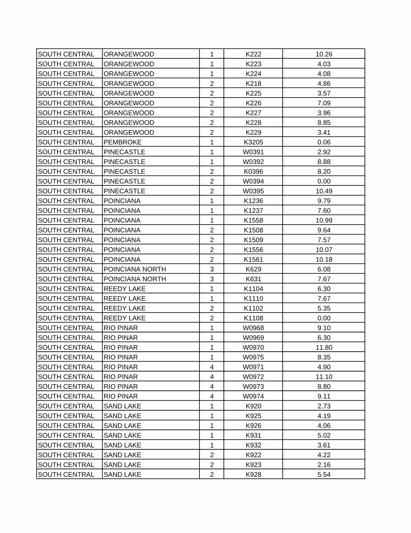
SOUTH CENTRAL ORANGEWOOD 1 K222 10.26SOUTH CENTRAL ORANGEWOOD 1 K223 4.03SOUTH CENTRAL ORANGEWOOD 1 K224 4.08SOUTH CENTRAL ORANGEWOOD 2 K218 4.86SOUTH CENTRAL ORANGEWOOD 2 K225 3.57SOUTH CENTRAL ORANGEWOOD 2 K226 7.09SOUTH CENTRAL ORANGEWOOD 2 K227 3.96SOUTH CENTRAL ORANGEWOOD 2 K228 8.85SOUTH CENTRAL ORANGEWOOD 2 K229 3.41SOUTH CENTRAL PEMBROKE 1 K3205 0.06SOUTH CENTRAL PINECASTLE 1 W0391 2.92SOUTH CENTRAL PINECASTLE 1 W0392 8.88SOUTH CENTRAL PINECASTLE 2 K0396 8.20SOUTH CENTRAL PINECASTLE 2 W0394 0.00SOUTH CENTRAL PINECASTLE 2 W0395 10.49SOUTH CENTRAL POINCIANA 1 K1236 9.79SOUTH CENTRAL POINCIANA 1 K1237 7.60SOUTH CENTRAL POINCIANA 1 K1558 10.99SOUTH CENTRAL POINCIANA 2 K1508 9.64SOUTH CENTRAL POINCIANA 2 K1509 7.57SOUTH CENTRAL POINCIANA 2 K1556 10.07SOUTH CENTRAL POINCIANA 2 K1561 10.18SOUTH CENTRAL POINCIANA NORTH 3 K629 6.08SOUTH CENTRAL POINCIANA NORTH 3 K631 7.67SOUTH CENTRAL REEDY LAKE 1 K1104 6.30SOUTH CENTRAL REEDY LAKE 1 K1110 7.67SOUTH CENTRAL REEDY LAKE 2 K1102 5.35SOUTH CENTRAL REEDY LAKE 2 K1108 0.00SOUTH CENTRAL RIO PINAR 1 W0968 9.10SOUTH CENTRAL RIO PINAR 1 W0969 6.30SOUTH CENTRAL RIO PINAR 1 W0970 11.80SOUTH CENTRAL RIO PINAR 1 W0975 8.35SOUTH CENTRAL RIO PINAR 4 W0971 4.90SOUTH CENTRAL RIO PINAR 4 W0972 11.10SOUTH CENTRAL RIO PINAR 4 W0973 8.80SOUTH CENTRAL RIO PINAR 4 W0974 9.11SOUTH CENTRAL SAND LAKE 1 K920 2.73SOUTH CENTRAL SAND LAKE 1 K925 4.19SOUTH CENTRAL SAND LAKE 1 K926 4.06SOUTH CENTRAL SAND LAKE 1 K931 5.02SOUTH CENTRAL SAND LAKE 1 K932 3.61SOUTH CENTRAL SAND LAKE 2 K922 4.22SOUTH CENTRAL SAND LAKE 2 K923 2.16SOUTH CENTRAL SAND LAKE 2 K928 5.54
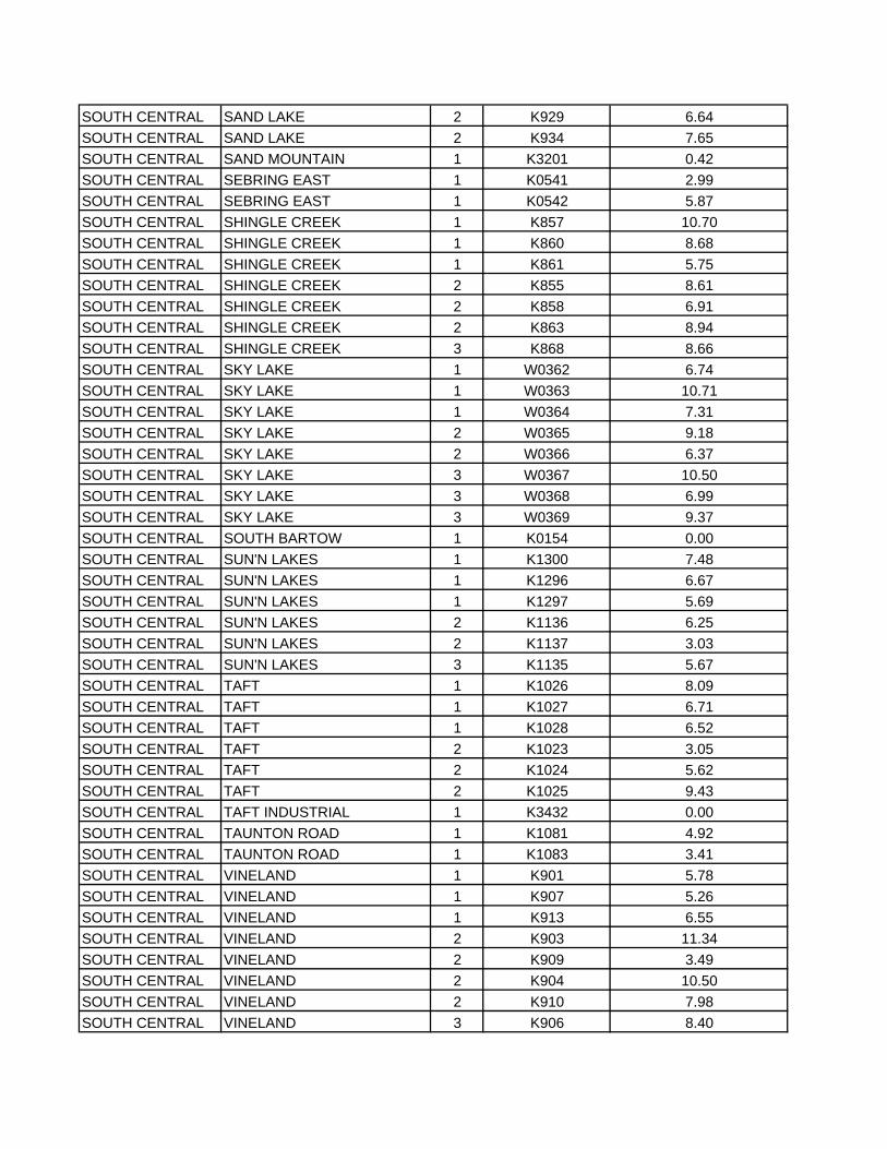
SOUTH CENTRAL SAND LAKE 2 K929 6.64SOUTH CENTRAL SAND LAKE 2 K934 7.65SOUTH CENTRAL SAND MOUNTAIN 1 K3201 0.42SOUTH CENTRAL SEBRING EAST 1 K0541 2.99SOUTH CENTRAL SEBRING EAST 1 K0542 5.87SOUTH CENTRAL SHINGLE CREEK 1 K857 10.70SOUTH CENTRAL SHINGLE CREEK 1 K860 8.68SOUTH CENTRAL SHINGLE CREEK 1 K861 5.75SOUTH CENTRAL SHINGLE CREEK 2 K855 8.61SOUTH CENTRAL SHINGLE CREEK 2 K858 6.91SOUTH CENTRAL SHINGLE CREEK 2 K863 8.94SOUTH CENTRAL SHINGLE CREEK 3 K868 8.66SOUTH CENTRAL SKY LAKE 1 W0362 6.74SOUTH CENTRAL SKY LAKE 1 W0363 10.71SOUTH CENTRAL SKY LAKE 1 W0364 7.31SOUTH CENTRAL SKY LAKE 2 W0365 9.18SOUTH CENTRAL SKY LAKE 2 W0366 6.37SOUTH CENTRAL SKY LAKE 3 W0367 10.50SOUTH CENTRAL SKY LAKE 3 W0368 6.99SOUTH CENTRAL SKY LAKE 3 W0369 9.37SOUTH CENTRAL SOUTH BARTOW 1 K0154 0.00SOUTH CENTRAL SUN'N LAKES 1 K1300 7.48SOUTH CENTRAL SUN'N LAKES 1 K1296 6.67SOUTH CENTRAL SUN'N LAKES 1 K1297 5.69SOUTH CENTRAL SUN'N LAKES 2 K1136 6.25SOUTH CENTRAL SUN'N LAKES 2 K1137 3.03SOUTH CENTRAL SUN'N LAKES 3 K1135 5.67SOUTH CENTRAL TAFT 1 K1026 8.09SOUTH CENTRAL TAFT 1 K1027 6.71SOUTH CENTRAL TAFT 1 K1028 6.52SOUTH CENTRAL TAFT 2 K1023 3.05SOUTH CENTRAL TAFT 2 K1024 5.62SOUTH CENTRAL TAFT 2 K1025 9.43SOUTH CENTRAL TAFT INDUSTRIAL 1 K3432 0.00SOUTH CENTRAL TAUNTON ROAD 1 K1081 4.92SOUTH CENTRAL TAUNTON ROAD 1 K1083 3.41SOUTH CENTRAL VINELAND 1 K901 5.78SOUTH CENTRAL VINELAND 1 K907 5.26SOUTH CENTRAL VINELAND 1 K913 6.55SOUTH CENTRAL VINELAND 2 K903 11.34SOUTH CENTRAL VINELAND 2 K909 3.49SOUTH CENTRAL VINELAND 2 K904 10.50SOUTH CENTRAL VINELAND 2 K910 7.98SOUTH CENTRAL VINELAND 3 K906 8.40
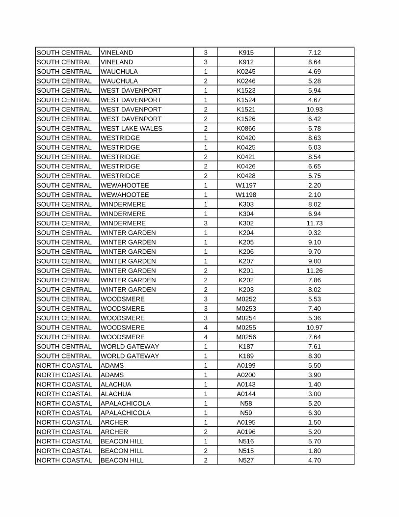
SOUTH CENTRAL VINELAND 3 K915 7.12SOUTH CENTRAL VINELAND 3 K912 8.64SOUTH CENTRAL WAUCHULA 1 K0245 4.69SOUTH CENTRAL WAUCHULA 2 K0246 5.28SOUTH CENTRAL WEST DAVENPORT 1 K1523 5.94SOUTH CENTRAL WEST DAVENPORT 1 K1524 4.67SOUTH CENTRAL WEST DAVENPORT 2 K1521 10.93SOUTH CENTRAL WEST DAVENPORT 2 K1526 6.42SOUTH CENTRAL WEST LAKE WALES 2 K0866 5.78SOUTH CENTRAL WESTRIDGE 1 K0420 8.63SOUTH CENTRAL WESTRIDGE 1 K0425 6.03SOUTH CENTRAL WESTRIDGE 2 K0421 8.54SOUTH CENTRAL WESTRIDGE 2 K0426 6.65SOUTH CENTRAL WESTRIDGE 2 K0428 5.75SOUTH CENTRAL WEWAHOOTEE 1 W1197 2.20SOUTH CENTRAL WEWAHOOTEE 1 W1198 2.10SOUTH CENTRAL WINDERMERE 1 K303 8.02SOUTH CENTRAL WINDERMERE 1 K304 6.94SOUTH CENTRAL WINDERMERE 3 K302 11.73SOUTH CENTRAL WINTER GARDEN 1 K204 9.32SOUTH CENTRAL WINTER GARDEN 1 K205 9.10SOUTH CENTRAL WINTER GARDEN 1 K206 9.70SOUTH CENTRAL WINTER GARDEN 1 K207 9.00SOUTH CENTRAL WINTER GARDEN 2 K201 11.26SOUTH CENTRAL WINTER GARDEN 2 K202 7.86SOUTH CENTRAL WINTER GARDEN 2 K203 8.02SOUTH CENTRAL WOODSMERE 3 M0252 5.53SOUTH CENTRAL WOODSMERE 3 M0253 7.40SOUTH CENTRAL WOODSMERE 3 M0254 5.36SOUTH CENTRAL WOODSMERE 4 M0255 10.97SOUTH CENTRAL WOODSMERE 4 M0256 7.64SOUTH CENTRAL WORLD GATEWAY 1 K187 7.61SOUTH CENTRAL WORLD GATEWAY 1 K189 8.30NORTH COASTAL ADAMS 1 A0199 5.50NORTH COASTAL ADAMS 1 A0200 3.90NORTH COASTAL ALACHUA 1 A0143 1.40NORTH COASTAL ALACHUA 1 A0144 3.00NORTH COASTAL APALACHICOLA 1 N58 5.20NORTH COASTAL APALACHICOLA 1 N59 6.30NORTH COASTAL ARCHER 1 A0195 1.50NORTH COASTAL ARCHER 2 A0196 5.20NORTH COASTAL BEACON HILL 1 N516 5.70NORTH COASTAL BEACON HILL 2 N515 1.80NORTH COASTAL BEACON HILL 2 N527 4.70
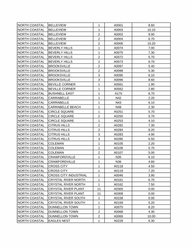
NORTH COASTAL BELLEVIEW 1 A0001 8.60NORTH COASTAL BELLEVIEW 1 A0003 10.10NORTH COASTAL BELLEVIEW 2 A0002 9.90NORTH COASTAL BELLEVIEW 2 A0004 6.70NORTH COASTAL BELLEVIEW 2 A0006 10.20NORTH COASTAL BEVERLY HILLS 1 A0074 7.00NORTH COASTAL BEVERLY HILLS 1 A0075 7.30NORTH COASTAL BEVERLY HILLS 2 A0072 5.70NORTH COASTAL BEVERLY HILLS 2 A0073 6.70NORTH COASTAL BROOKSVILLE 2 A0097 5.40NORTH COASTAL BROOKSVILLE 2 A0098 5.30NORTH COASTAL BROOKSVILLE 3 A0095 6.10NORTH COASTAL BROOKSVILLE 3 A0096 8.60NORTH COASTAL BEVILLE CORNER 1 A0561 1.90NORTH COASTAL BEVILLE CORNER 1 A0562 2.80NORTH COASTAL BUSHNELL EAST 1 A170 6.70NORTH COASTAL CARRABELLE 1 N42 2.20NORTH COASTAL CARRABELLE 1 N43 6.10NORTH COASTAL CARRABELLE BEACH 1 N48 2.30NORTH COASTAL CIRCLE SQUARE 1 A0251 5.70NORTH COASTAL CIRCLE SQUARE 2 A0250 5.70NORTH COASTAL CIRCLE SQUARE 1 A0253 4.10NORTH COASTAL CITRUS HILLS 2 A0282 7.30NORTH COASTAL CITRUS HILLS 2 A0284 8.20NORTH COASTAL CITRUS HILLS 3 A0283 4.90NORTH COASTAL CITRUS HILLS 3 A0285 6.50NORTH COASTAL COLEMAN 1 A0105 2.20NORTH COASTAL COLEMAN 1 A0106 5.70NORTH COASTAL COLEMAN 2 A0107 5.00NORTH COASTAL CRAWFORDVILLE 1 N35 6.10NORTH COASTAL CRAWFORDVILLE 1 N36 4.60NORTH COASTAL CROSS CITY 1 A0118 4.50NORTH COASTAL CROSS CITY 1 A0119 7.20NORTH COASTAL CROSS CITY INDUSTRIAL 1 A0046 3.90NORTH COASTAL CRYSTAL RIVER NORTH 1 A0161 6.70NORTH COASTAL CRYSTAL RIVER NORTH 1 A0162 7.50NORTH COASTAL CRYSTAL RIVER PLANT 11 A0300 0.00NORTH COASTAL CRYSTAL RIVER PLANT 11 A0308 0.00NORTH COASTAL CRYSTAL RIVER SOUTH 1 A0158 0.00NORTH COASTAL CRYSTAL RIVER SOUTH 1 A0159 5.20NORTH COASTAL DUNNELLON TOWN 1 A0070 8.20NORTH COASTAL DUNNELLON TOWN 2 A0068 4.30NORTH COASTAL DUNNELLON TOWN 2 A0069 10.00NORTH COASTAL EAGLES NEST 1 A0228 6.30
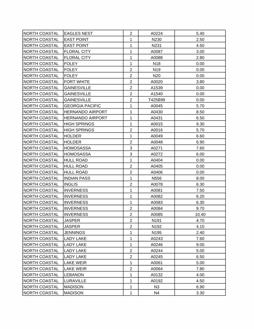
NORTH COASTAL EAGLES NEST 2 A0224 5.40NORTH COASTAL EAST POINT 1 N230 2.50NORTH COASTAL EAST POINT 1 N231 4.50NORTH COASTAL FLORAL CITY 1 A0087 3.00NORTH COASTAL FLORAL CITY 1 A0088 2.80NORTH COASTAL FOLEY 1 N18 0.00NORTH COASTAL FOLEY 2 N19 0.00NORTH COASTAL FOLEY 2 N20 0.00NORTH COASTAL FORT WHITE 2 A0020 3.80NORTH COASTAL GAINESVILLE 2 A1539 0.00NORTH COASTAL GAINESVILLE 2 A1540 0.00NORTH COASTAL GAINESVILLE 2 T425B99 0.00NORTH COASTAL GEORGIA PACIFIC 1 A0045 5.70NORTH COASTAL HERNANDO AIRPORT 1 A0430 8.50NORTH COASTAL HERNANDO AIRPORT 1 A0431 6.50NORTH COASTAL HIGH SPRINGS 1 A0015 9.30NORTH COASTAL HIGH SPRINGS 2 A0016 5.70NORTH COASTAL HOLDER 1 A0049 6.60NORTH COASTAL HOLDER 2 A0048 6.90NORTH COASTAL HOMOSASSA 3 A0271 7.60NORTH COASTAL HOMOSASSA 3 A0272 6.00NORTH COASTAL HULL ROAD 1 A0404 0.00NORTH COASTAL HULL ROAD 2 A0405 0.00NORTH COASTAL HULL ROAD 2 A0406 0.00NORTH COASTAL INDIAN PASS 1 N556 8.00NORTH COASTAL INGLIS 2 A0078 6.30NORTH COASTAL INVERNESS 1 A0081 7.50NORTH COASTAL INVERNESS 1 A0082 6.20NORTH COASTAL INVERNESS 1 A0083 6.30NORTH COASTAL INVERNESS 2 A0084 9.70NORTH COASTAL INVERNESS 2 A0085 10.40NORTH COASTAL JASPER 2 N191 4.70NORTH COASTAL JASPER 2 N192 4.10NORTH COASTAL JENNINGS 1 N195 2.40NORTH COASTAL LADY LAKE 1 A0243 7.60NORTH COASTAL LADY LAKE 1 A0246 9.00NORTH COASTAL LADY LAKE 2 A0244 5.00NORTH COASTAL LADY LAKE 2 A0245 6.50NORTH COASTAL LAKE WEIR 1 A0061 5.00NORTH COASTAL LAKE WEIR 2 A0064 7.80NORTH COASTAL LEBANON 1 A0132 4.00NORTH COASTAL LURAVILLE 1 A0192 4.50NORTH COASTAL MADISON 1 N3 6.90NORTH COASTAL MADISON 1 N4 3.30
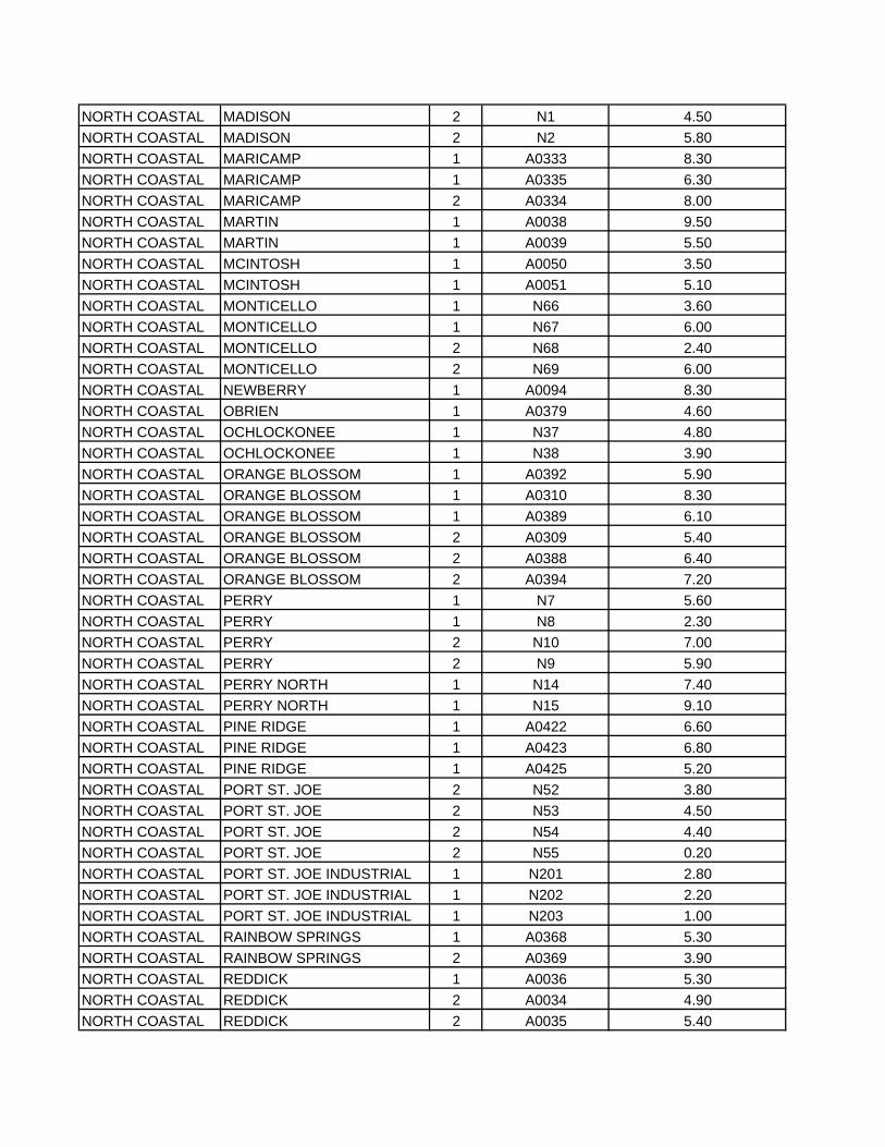
NORTH COASTAL MADISON 2 N1 4.50NORTH COASTAL MADISON 2 N2 5.80NORTH COASTAL MARICAMP 1 A0333 8.30NORTH COASTAL MARICAMP 1 A0335 6.30NORTH COASTAL MARICAMP 2 A0334 8.00NORTH COASTAL MARTIN 1 A0038 9.50NORTH COASTAL MARTIN 1 A0039 5.50NORTH COASTAL MCINTOSH 1 A0050 3.50NORTH COASTAL MCINTOSH 1 A0051 5.10NORTH COASTAL MONTICELLO 1 N66 3.60NORTH COASTAL MONTICELLO 1 N67 6.00NORTH COASTAL MONTICELLO 2 N68 2.40NORTH COASTAL MONTICELLO 2 N69 6.00NORTH COASTAL NEWBERRY 1 A0094 8.30NORTH COASTAL OBRIEN 1 A0379 4.60NORTH COASTAL OCHLOCKONEE 1 N37 4.80NORTH COASTAL OCHLOCKONEE 1 N38 3.90NORTH COASTAL ORANGE BLOSSOM 1 A0392 5.90NORTH COASTAL ORANGE BLOSSOM 1 A0310 8.30NORTH COASTAL ORANGE BLOSSOM 1 A0389 6.10NORTH COASTAL ORANGE BLOSSOM 2 A0309 5.40NORTH COASTAL ORANGE BLOSSOM 2 A0388 6.40NORTH COASTAL ORANGE BLOSSOM 2 A0394 7.20NORTH COASTAL PERRY 1 N7 5.60NORTH COASTAL PERRY 1 N8 2.30NORTH COASTAL PERRY 2 N10 7.00NORTH COASTAL PERRY 2 N9 5.90NORTH COASTAL PERRY NORTH 1 N14 7.40NORTH COASTAL PERRY NORTH 1 N15 9.10NORTH COASTAL PINE RIDGE 1 A0422 6.60NORTH COASTAL PINE RIDGE 1 A0423 6.80NORTH COASTAL PINE RIDGE 1 A0425 5.20NORTH COASTAL PORT ST. JOE 2 N52 3.80NORTH COASTAL PORT ST. JOE 2 N53 4.50NORTH COASTAL PORT ST. JOE 2 N54 4.40NORTH COASTAL PORT ST. JOE 2 N55 0.20NORTH COASTAL PORT ST. JOE INDUSTRIAL 1 N201 2.80NORTH COASTAL PORT ST. JOE INDUSTRIAL 1 N202 2.20NORTH COASTAL PORT ST. JOE INDUSTRIAL 1 N203 1.00NORTH COASTAL RAINBOW SPRINGS 1 A0368 5.30NORTH COASTAL RAINBOW SPRINGS 2 A0369 3.90NORTH COASTAL REDDICK 1 A0036 5.30NORTH COASTAL REDDICK 2 A0034 4.90NORTH COASTAL REDDICK 2 A0035 5.40
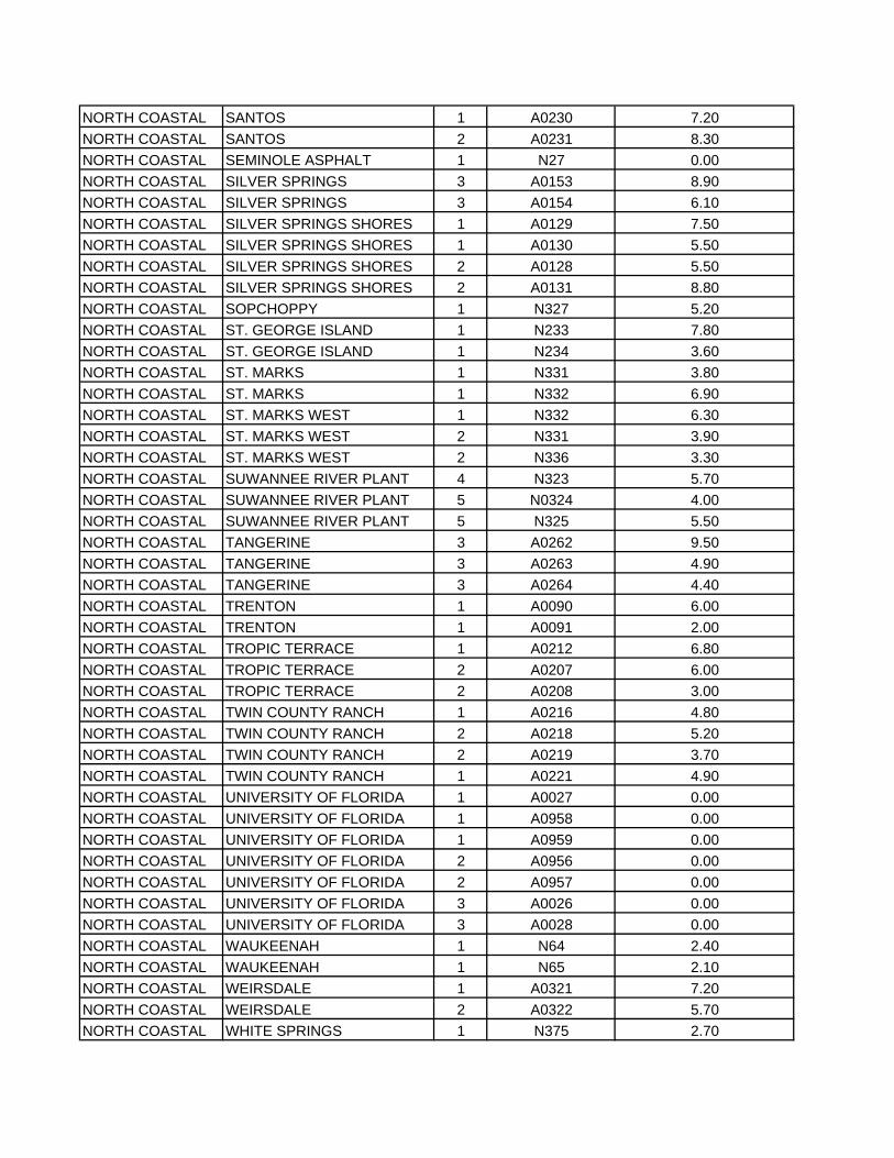
NORTH COASTAL SANTOS 1 A0230 7.20NORTH COASTAL SANTOS 2 A0231 8.30NORTH COASTAL SEMINOLE ASPHALT 1 N27 0.00NORTH COASTAL SILVER SPRINGS 3 A0153 8.90NORTH COASTAL SILVER SPRINGS 3 A0154 6.10NORTH COASTAL SILVER SPRINGS SHORES 1 A0129 7.50NORTH COASTAL SILVER SPRINGS SHORES 1 A0130 5.50NORTH COASTAL SILVER SPRINGS SHORES 2 A0128 5.50NORTH COASTAL SILVER SPRINGS SHORES 2 A0131 8.80NORTH COASTAL SOPCHOPPY 1 N327 5.20NORTH COASTAL ST. GEORGE ISLAND 1 N233 7.80NORTH COASTAL ST. GEORGE ISLAND 1 N234 3.60NORTH COASTAL ST. MARKS 1 N331 3.80NORTH COASTAL ST. MARKS 1 N332 6.90NORTH COASTAL ST. MARKS WEST 1 N332 6.30NORTH COASTAL ST. MARKS WEST 2 N331 3.90NORTH COASTAL ST. MARKS WEST 2 N336 3.30NORTH COASTAL SUWANNEE RIVER PLANT 4 N323 5.70NORTH COASTAL SUWANNEE RIVER PLANT 5 N0324 4.00NORTH COASTAL SUWANNEE RIVER PLANT 5 N325 5.50NORTH COASTAL TANGERINE 3 A0262 9.50NORTH COASTAL TANGERINE 3 A0263 4.90NORTH COASTAL TANGERINE 3 A0264 4.40NORTH COASTAL TRENTON 1 A0090 6.00NORTH COASTAL TRENTON 1 A0091 2.00NORTH COASTAL TROPIC TERRACE 1 A0212 6.80NORTH COASTAL TROPIC TERRACE 2 A0207 6.00NORTH COASTAL TROPIC TERRACE 2 A0208 3.00NORTH COASTAL TWIN COUNTY RANCH 1 A0216 4.80NORTH COASTAL TWIN COUNTY RANCH 2 A0218 5.20NORTH COASTAL TWIN COUNTY RANCH 2 A0219 3.70NORTH COASTAL TWIN COUNTY RANCH 1 A0221 4.90NORTH COASTAL UNIVERSITY OF FLORIDA 1 A0027 0.00NORTH COASTAL UNIVERSITY OF FLORIDA 1 A0958 0.00NORTH COASTAL UNIVERSITY OF FLORIDA 1 A0959 0.00NORTH COASTAL UNIVERSITY OF FLORIDA 2 A0956 0.00NORTH COASTAL UNIVERSITY OF FLORIDA 2 A0957 0.00NORTH COASTAL UNIVERSITY OF FLORIDA 3 A0026 0.00NORTH COASTAL UNIVERSITY OF FLORIDA 3 A0028 0.00NORTH COASTAL WAUKEENAH 1 N64 2.40NORTH COASTAL WAUKEENAH 1 N65 2.10NORTH COASTAL WEIRSDALE 1 A0321 7.20NORTH COASTAL WEIRSDALE 2 A0322 5.70NORTH COASTAL WHITE SPRINGS 1 N375 2.70
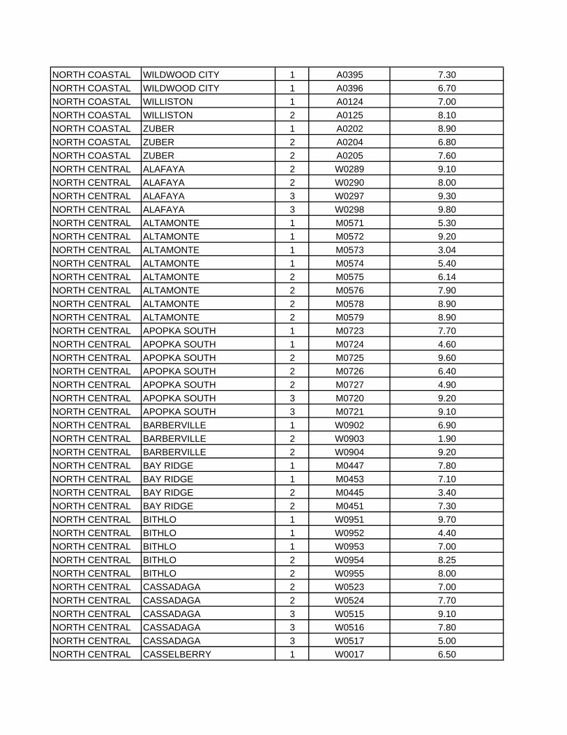
NORTH COASTAL WILDWOOD CITY 1 A0395 7.30NORTH COASTAL WILDWOOD CITY 1 A0396 6.70NORTH COASTAL WILLISTON 1 A0124 7.00NORTH COASTAL WILLISTON 2 A0125 8.10NORTH COASTAL ZUBER 1 A0202 8.90NORTH COASTAL ZUBER 2 A0204 6.80NORTH COASTAL ZUBER 2 A0205 7.60NORTH CENTRAL ALAFAYA 2 W0289 9.10NORTH CENTRAL ALAFAYA 2 W0290 8.00NORTH CENTRAL ALAFAYA 3 W0297 9.30NORTH CENTRAL ALAFAYA 3 W0298 9.80NORTH CENTRAL ALTAMONTE 1 M0571 5.30NORTH CENTRAL ALTAMONTE 1 M0572 9.20NORTH CENTRAL ALTAMONTE 1 M0573 3.04NORTH CENTRAL ALTAMONTE 1 M0574 5.40NORTH CENTRAL ALTAMONTE 2 M0575 6.14NORTH CENTRAL ALTAMONTE 2 M0576 7.90NORTH CENTRAL ALTAMONTE 2 M0578 8.90NORTH CENTRAL ALTAMONTE 2 M0579 8.90NORTH CENTRAL APOPKA SOUTH 1 M0723 7.70NORTH CENTRAL APOPKA SOUTH 1 M0724 4.60NORTH CENTRAL APOPKA SOUTH 2 M0725 9.60NORTH CENTRAL APOPKA SOUTH 2 M0726 6.40NORTH CENTRAL APOPKA SOUTH 2 M0727 4.90NORTH CENTRAL APOPKA SOUTH 3 M0720 9.20NORTH CENTRAL APOPKA SOUTH 3 M0721 9.10NORTH CENTRAL BARBERVILLE 1 W0902 6.90NORTH CENTRAL BARBERVILLE 2 W0903 1.90NORTH CENTRAL BARBERVILLE 2 W0904 9.20NORTH CENTRAL BAY RIDGE 1 M0447 7.80NORTH CENTRAL BAY RIDGE 1 M0453 7.10NORTH CENTRAL BAY RIDGE 2 M0445 3.40NORTH CENTRAL BAY RIDGE 2 M0451 7.30NORTH CENTRAL BITHLO 1 W0951 9.70NORTH CENTRAL BITHLO 1 W0952 4.40NORTH CENTRAL BITHLO 1 W0953 7.00NORTH CENTRAL BITHLO 2 W0954 8.25NORTH CENTRAL BITHLO 2 W0955 8.00NORTH CENTRAL CASSADAGA 2 W0523 7.00NORTH CENTRAL CASSADAGA 2 W0524 7.70NORTH CENTRAL CASSADAGA 3 W0515 9.10NORTH CENTRAL CASSADAGA 3 W0516 7.80NORTH CENTRAL CASSADAGA 3 W0517 5.00NORTH CENTRAL CASSELBERRY 1 W0017 6.50
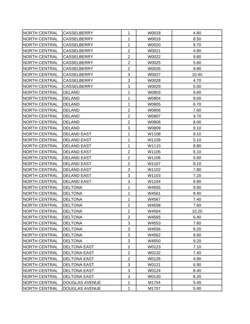
NORTH CENTRAL CASSELBERRY 1 W0018 4.80NORTH CENTRAL CASSELBERRY 1 W0019 8.50NORTH CENTRAL CASSELBERRY 1 W0020 9.70NORTH CENTRAL CASSELBERRY 2 W0021 4.90NORTH CENTRAL CASSELBERRY 2 W0022 9.80NORTH CENTRAL CASSELBERRY 2 W0025 5.60NORTH CENTRAL CASSELBERRY 2 W0026 9.80NORTH CENTRAL CASSELBERRY 3 W0027 10.40NORTH CENTRAL CASSELBERRY 3 W0028 4.70NORTH CENTRAL CASSELBERRY 3 W0029 5.00NORTH CENTRAL DELAND 1 W0803 9.60NORTH CENTRAL DELAND 1 W0804 9.00NORTH CENTRAL DELAND 1 W0805 6.70NORTH CENTRAL DELAND 2 W0806 7.60NORTH CENTRAL DELAND 2 W0807 9.70NORTH CENTRAL DELAND 2 W0808 8.00NORTH CENTRAL DELAND 3 W0809 9.10NORTH CENTRAL DELAND EAST 1 W1108 9.10NORTH CENTRAL DELAND EAST 1 W1109 5.10NORTH CENTRAL DELAND EAST 1 W1110 8.80NORTH CENTRAL DELAND EAST 2 W1105 6.10NORTH CENTRAL DELAND EAST 2 W1106 5.60NORTH CENTRAL DELAND EAST 2 W1107 8.10NORTH CENTRAL DELAND EAST 3 W1102 7.80NORTH CENTRAL DELAND EAST 3 W1103 7.20NORTH CENTRAL DELAND EAST 3 W1104 6.90NORTH CENTRAL DELTONA 1 W4555 9.90NORTH CENTRAL DELTONA 1 W4561 9.40NORTH CENTRAL DELTONA 1 W4567 7.40NORTH CENTRAL DELTONA 2 W4558 7.60NORTH CENTRAL DELTONA 2 W4564 10.20NORTH CENTRAL DELTONA 2 W4565 6.40NORTH CENTRAL DELTONA 3 W4553 7.80NORTH CENTRAL DELTONA 3 W4556 8.20NORTH CENTRAL DELTONA 3 W4562 9.60NORTH CENTRAL DELTONA 3 W4550 9.20NORTH CENTRAL DELTONA EAST 2 W0123 7.10NORTH CENTRAL DELTONA EAST 2 W0132 7.40NORTH CENTRAL DELTONA EAST 2 W0126 4.90NORTH CENTRAL DELTONA EAST 3 W0121 6.90NORTH CENTRAL DELTONA EAST 3 W0124 8.40NORTH CENTRAL DELTONA EAST 3 W0130 8.20NORTH CENTRAL DOUGLAS AVENUE 1 M1704 5.40NORTH CENTRAL DOUGLAS AVENUE 1 M1707 5.90
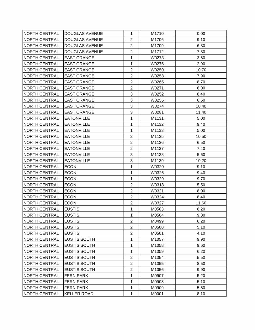
NORTH CENTRAL DOUGLAS AVENUE 1 M1710 0.00NORTH CENTRAL DOUGLAS AVENUE 2 M1706 9.10NORTH CENTRAL DOUGLAS AVENUE 2 M1709 6.80NORTH CENTRAL DOUGLAS AVENUE 2 M1712 7.30NORTH CENTRAL EAST ORANGE 1 W0273 3.60NORTH CENTRAL EAST ORANGE 1 W0276 2.90NORTH CENTRAL EAST ORANGE 2 W0250 10.70NORTH CENTRAL EAST ORANGE 2 W0253 7.90NORTH CENTRAL EAST ORANGE 2 W0265 8.70NORTH CENTRAL EAST ORANGE 2 W0271 8.00NORTH CENTRAL EAST ORANGE 3 W0252 8.40NORTH CENTRAL EAST ORANGE 3 W0255 6.50NORTH CENTRAL EAST ORANGE 3 W0274 10.40NORTH CENTRAL EAST ORANGE 3 W0281 11.40NORTH CENTRAL EATONVILLE 1 M1131 5.00NORTH CENTRAL EATONVILLE 1 M1132 9.40NORTH CENTRAL EATONVILLE 1 M1133 5.00NORTH CENTRAL EATONVILLE 2 M1135 10.50NORTH CENTRAL EATONVILLE 2 M1136 6.50NORTH CENTRAL EATONVILLE 2 M1137 7.40NORTH CENTRAL EATONVILLE 3 M1138 5.60NORTH CENTRAL EATONVILLE 3 M1139 10.20NORTH CENTRAL ECON 1 W0320 9.10NORTH CENTRAL ECON 1 W0326 9.40NORTH CENTRAL ECON 1 W0329 9.70NORTH CENTRAL ECON 2 W0318 5.50NORTH CENTRAL ECON 2 W0321 8.00NORTH CENTRAL ECON 2 W0324 8.40NORTH CENTRAL ECON 2 W0327 11.60NORTH CENTRAL EUSTIS 1 M0503 6.20NORTH CENTRAL EUSTIS 1 M0504 9.80NORTH CENTRAL EUSTIS 2 M0499 6.20NORTH CENTRAL EUSTIS 2 M0500 5.10NORTH CENTRAL EUSTIS 2 M0501 4.10NORTH CENTRAL EUSTIS SOUTH 1 M1057 9.90NORTH CENTRAL EUSTIS SOUTH 1 M1058 9.60NORTH CENTRAL EUSTIS SOUTH 1 M1059 6.20NORTH CENTRAL EUSTIS SOUTH 2 M1054 5.50NORTH CENTRAL EUSTIS SOUTH 2 M1055 8.50NORTH CENTRAL EUSTIS SOUTH 2 M1056 9.90NORTH CENTRAL FERN PARK 1 M0907 5.20NORTH CENTRAL FERN PARK 1 M0908 5.10NORTH CENTRAL FERN PARK 1 M0909 5.50NORTH CENTRAL KELLER ROAD 1 M0001 8.10
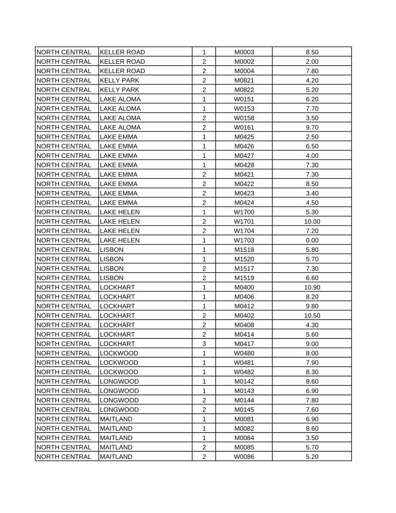
NORTH CENTRAL KELLER ROAD 1 M0003 8.50NORTH CENTRAL KELLER ROAD 2 M0002 2.00NORTH CENTRAL KELLER ROAD 2 M0004 7.80NORTH CENTRAL KELLY PARK 2 M0821 4.20NORTH CENTRAL KELLY PARK 2 M0822 5.20NORTH CENTRAL LAKE ALOMA 1 W0151 6.20NORTH CENTRAL LAKE ALOMA 1 W0153 7.70NORTH CENTRAL LAKE ALOMA 2 W0158 3.50NORTH CENTRAL LAKE ALOMA 2 W0161 9.70NORTH CENTRAL LAKE EMMA 1 M0425 2.50NORTH CENTRAL LAKE EMMA 1 M0426 6.50NORTH CENTRAL LAKE EMMA 1 M0427 4.00NORTH CENTRAL LAKE EMMA 1 M0428 7.30NORTH CENTRAL LAKE EMMA 2 M0421 7.30NORTH CENTRAL LAKE EMMA 2 M0422 8.50NORTH CENTRAL LAKE EMMA 2 M0423 3.40NORTH CENTRAL LAKE EMMA 2 M0424 4.50NORTH CENTRAL LAKE HELEN 1 W1700 5.30NORTH CENTRAL LAKE HELEN 2 W1701 10.00NORTH CENTRAL LAKE HELEN 2 W1704 7.20NORTH CENTRAL LAKE HELEN 1 W1703 0.00NORTH CENTRAL LISBON 1 M1518 5.80NORTH CENTRAL LISBON 1 M1520 5.70NORTH CENTRAL LISBON 2 M1517 7.30NORTH CENTRAL LISBON 2 M1519 6.60NORTH CENTRAL LOCKHART 1 M0400 10.90NORTH CENTRAL LOCKHART 1 M0406 8.20NORTH CENTRAL LOCKHART 1 M0412 9.80NORTH CENTRAL LOCKHART 2 M0402 10.50NORTH CENTRAL LOCKHART 2 M0408 4.30NORTH CENTRAL LOCKHART 2 M0414 5.60NORTH CENTRAL LOCKHART 3 M0417 9.00NORTH CENTRAL LOCKWOOD 1 W0480 8.00NORTH CENTRAL LOCKWOOD 1 W0481 7.90NORTH CENTRAL LOCKWOOD 1 W0482 8.30NORTH CENTRAL LONGWOOD 1 M0142 8.60NORTH CENTRAL LONGWOOD 1 M0143 6.90NORTH CENTRAL LONGWOOD 2 M0144 7.80NORTH CENTRAL LONGWOOD 2 M0145 7.60NORTH CENTRAL MAITLAND 1 M0081 6.90NORTH CENTRAL MAITLAND 1 M0082 8.60NORTH CENTRAL MAITLAND 1 M0084 3.50NORTH CENTRAL MAITLAND 2 M0085 5.70NORTH CENTRAL MAITLAND 2 W0086 5.20
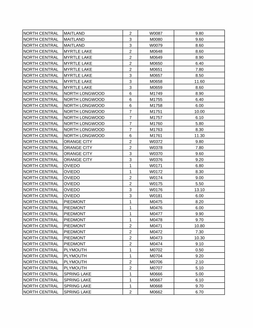
NORTH CENTRAL MAITLAND 2 W0087 9.80NORTH CENTRAL MAITLAND 3 M0080 9.60NORTH CENTRAL MAITLAND 3 W0079 8.60NORTH CENTRAL MYRTLE LAKE 2 M0648 8.60NORTH CENTRAL MYRTLE LAKE 2 M0649 8.90NORTH CENTRAL MYRTLE LAKE 2 M0650 6.40NORTH CENTRAL MYRTLE LAKE 2 M0651 7.80NORTH CENTRAL MYRTLE LAKE 3 M0657 8.50NORTH CENTRAL MYRTLE LAKE 3 M0658 11.60NORTH CENTRAL MYRTLE LAKE 3 M0659 8.60NORTH CENTRAL NORTH LONGWOOD 6 M1749 8.90NORTH CENTRAL NORTH LONGWOOD 6 M1755 6.40NORTH CENTRAL NORTH LONGWOOD 6 M1758 6.00NORTH CENTRAL NORTH LONGWOOD 7 M1751 10.00NORTH CENTRAL NORTH LONGWOOD 7 M1757 6.10NORTH CENTRAL NORTH LONGWOOD 7 M1760 5.80NORTH CENTRAL NORTH LONGWOOD 7 M1763 8.30NORTH CENTRAL NORTH LONGWOOD 6 M1761 11.30NORTH CENTRAL ORANGE CITY 2 W0372 9.80NORTH CENTRAL ORANGE CITY 2 W0378 7.80NORTH CENTRAL ORANGE CITY 3 W0370 9.60NORTH CENTRAL ORANGE CITY 3 W0376 9.20NORTH CENTRAL OVIEDO 1 W0171 6.80NORTH CENTRAL OVIEDO 1 W0172 8.30NORTH CENTRAL OVIEDO 2 W0174 9.00NORTH CENTRAL OVIEDO 2 W0175 5.50NORTH CENTRAL OVIEDO 3 W0176 13.10NORTH CENTRAL OVIEDO 3 W0181 6.00NORTH CENTRAL PIEDMONT 1 M0475 8.20NORTH CENTRAL PIEDMONT 1 M0476 6.00NORTH CENTRAL PIEDMONT 1 M0477 9.90NORTH CENTRAL PIEDMONT 1 M0478 9.70NORTH CENTRAL PIEDMONT 2 M0471 10.80NORTH CENTRAL PIEDMONT 2 M0472 7.30NORTH CENTRAL PIEDMONT 2 M0473 10.30NORTH CENTRAL PIEDMONT 2 M0474 9.10NORTH CENTRAL PLYMOUTH 1 M0702 0.50NORTH CENTRAL PLYMOUTH 1 M0704 9.20NORTH CENTRAL PLYMOUTH 2 M0706 2.10NORTH CENTRAL PLYMOUTH 2 M0707 5.10NORTH CENTRAL SPRING LAKE 1 M0666 5.00NORTH CENTRAL SPRING LAKE 1 M0667 6.10NORTH CENTRAL SPRING LAKE 1 M0668 9.70NORTH CENTRAL SPRING LAKE 2 M0662 6.70
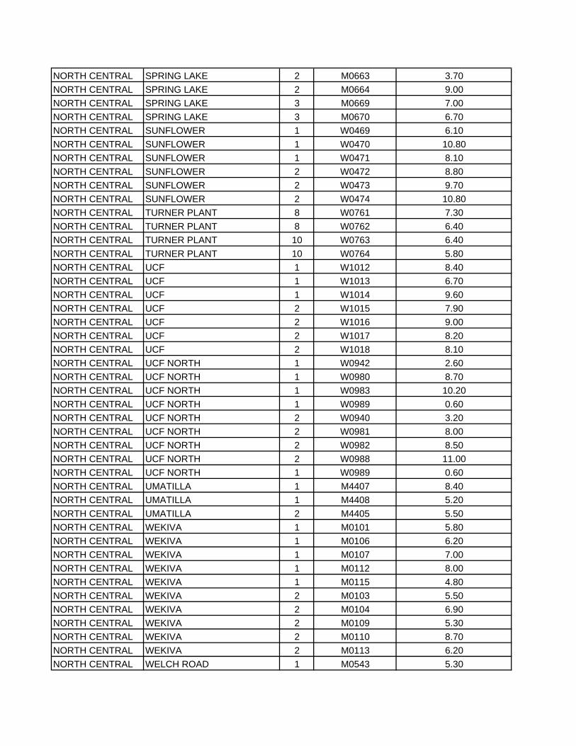
NORTH CENTRAL SPRING LAKE 2 M0663 3.70NORTH CENTRAL SPRING LAKE 2 M0664 9.00NORTH CENTRAL SPRING LAKE 3 M0669 7.00NORTH CENTRAL SPRING LAKE 3 M0670 6.70NORTH CENTRAL SUNFLOWER 1 W0469 6.10NORTH CENTRAL SUNFLOWER 1 W0470 10.80NORTH CENTRAL SUNFLOWER 1 W0471 8.10NORTH CENTRAL SUNFLOWER 2 W0472 8.80NORTH CENTRAL SUNFLOWER 2 W0473 9.70NORTH CENTRAL SUNFLOWER 2 W0474 10.80NORTH CENTRAL TURNER PLANT 8 W0761 7.30NORTH CENTRAL TURNER PLANT 8 W0762 6.40NORTH CENTRAL TURNER PLANT 10 W0763 6.40NORTH CENTRAL TURNER PLANT 10 W0764 5.80NORTH CENTRAL UCF 1 W1012 8.40NORTH CENTRAL UCF 1 W1013 6.70NORTH CENTRAL UCF 1 W1014 9.60NORTH CENTRAL UCF 2 W1015 7.90NORTH CENTRAL UCF 2 W1016 9.00NORTH CENTRAL UCF 2 W1017 8.20NORTH CENTRAL UCF 2 W1018 8.10NORTH CENTRAL UCF NORTH 1 W0942 2.60NORTH CENTRAL UCF NORTH 1 W0980 8.70NORTH CENTRAL UCF NORTH 1 W0983 10.20NORTH CENTRAL UCF NORTH 1 W0989 0.60NORTH CENTRAL UCF NORTH 2 W0940 3.20NORTH CENTRAL UCF NORTH 2 W0981 8.00NORTH CENTRAL UCF NORTH 2 W0982 8.50NORTH CENTRAL UCF NORTH 2 W0988 11.00NORTH CENTRAL UCF NORTH 1 W0989 0.60NORTH CENTRAL UMATILLA 1 M4407 8.40NORTH CENTRAL UMATILLA 1 M4408 5.20NORTH CENTRAL UMATILLA 2 M4405 5.50NORTH CENTRAL WEKIVA 1 M0101 5.80NORTH CENTRAL WEKIVA 1 M0106 6.20NORTH CENTRAL WEKIVA 1 M0107 7.00NORTH CENTRAL WEKIVA 1 M0112 8.00NORTH CENTRAL WEKIVA 1 M0115 4.80NORTH CENTRAL WEKIVA 2 M0103 5.50NORTH CENTRAL WEKIVA 2 M0104 6.90NORTH CENTRAL WEKIVA 2 M0109 5.30NORTH CENTRAL WEKIVA 2 M0110 8.70NORTH CENTRAL WEKIVA 2 M0113 6.20NORTH CENTRAL WELCH ROAD 1 M0543 5.30
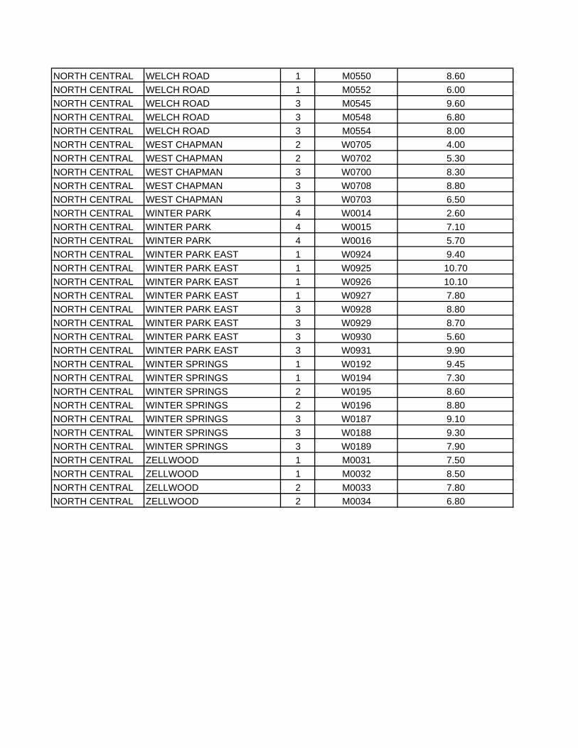
NORTH CENTRAL WELCH ROAD 1 M0550 8.60NORTH CENTRAL WELCH ROAD 1 M0552 6.00NORTH CENTRAL WELCH ROAD 3 M0545 9.60NORTH CENTRAL WELCH ROAD 3 M0548 6.80NORTH CENTRAL WELCH ROAD 3 M0554 8.00NORTH CENTRAL WEST CHAPMAN 2 W0705 4.00NORTH CENTRAL WEST CHAPMAN 2 W0702 5.30NORTH CENTRAL WEST CHAPMAN 3 W0700 8.30NORTH CENTRAL WEST CHAPMAN 3 W0708 8.80NORTH CENTRAL WEST CHAPMAN 3 W0703 6.50NORTH CENTRAL WINTER PARK 4 W0014 2.60NORTH CENTRAL WINTER PARK 4 W0015 7.10NORTH CENTRAL WINTER PARK 4 W0016 5.70NORTH CENTRAL WINTER PARK EAST 1 W0924 9.40NORTH CENTRAL WINTER PARK EAST 1 W0925 10.70NORTH CENTRAL WINTER PARK EAST 1 W0926 10.10NORTH CENTRAL WINTER PARK EAST 1 W0927 7.80NORTH CENTRAL WINTER PARK EAST 3 W0928 8.80NORTH CENTRAL WINTER PARK EAST 3 W0929 8.70NORTH CENTRAL WINTER PARK EAST 3 W0930 5.60NORTH CENTRAL WINTER PARK EAST 3 W0931 9.90NORTH CENTRAL WINTER SPRINGS 1 W0192 9.45NORTH CENTRAL WINTER SPRINGS 1 W0194 7.30NORTH CENTRAL WINTER SPRINGS 2 W0195 8.60NORTH CENTRAL WINTER SPRINGS 2 W0196 8.80NORTH CENTRAL WINTER SPRINGS 3 W0187 9.10NORTH CENTRAL WINTER SPRINGS 3 W0188 9.30NORTH CENTRAL WINTER SPRINGS 3 W0189 7.90NORTH CENTRAL ZELLWOOD 1 M0031 7.50NORTH CENTRAL ZELLWOOD 1 M0032 8.50NORTH CENTRAL ZELLWOOD 2 M0033 7.80NORTH CENTRAL ZELLWOOD 2 M0034 6.80

ATTACHMENT H
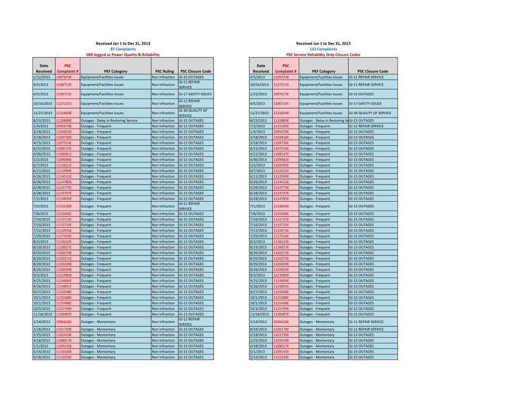
DateReceived
PSCComplaint # PEF Category PSC Ruling PSC Closure Code
DateReceived
PSCComplaint # PEF Category PSC Closure Code
1/22/2013 1097673E Equipment/Facilities Issues Non Infraction GI‐15 OUTAGES 4/5/2013 1106723E Equipment/Facilities Issues GI‐11 REPAIR SERVICE
4/5/2013 1106723E Equipment/Facilities Issues Non InfractionGI‐11 REPAIR SERVICE
10/16/2013 1127221E Equipment/Facilities Issues GI‐11 REPAIR SERVICE
4/5/2013 1106715E Equipment/Facilities Issues Non Infraction GI‐17 SAFETY ISSUES 1/22/2013 1097673E Equipment/Facilities Issues GI‐15 OUTAGES
10/16/2013 1127221E Equipment/Facilities Issues Non InfractionGI‐11 REPAIR SERVICE
4/5/2013 1106715E Equipment/Facilities Issues GI‐17 SAFETY ISSUES
11/27/2013 1131604E Equipment/Facilities Issues Non InfractionGI‐30 QUALITY OF SERVICE
11/27/2013 1131604E Equipment/Facilities Issues GI‐30 QUALITY OF SERVICE
8/23/2013 1120889E Outages ‐ Delay in Restoring Service Non Infraction GI‐15 OUTAGES 8/23/2013 1120889E Outages ‐ Delay in Restoring SeGI‐15 OUTAGES1/4/2013 1095678E Outages ‐ Frequent Non Infraction GI‐15 OUTAGES 7/2/2013 1115100E Outages ‐ Frequent GI‐11 REPAIR SERVICE3/18/2013 1104816E Outages ‐ Frequent Non Infraction GI‐15 OUTAGES 1/4/2013 1095678E Outages ‐ Frequent GI‐15 OUTAGES3/18/2013 1104730E Outages ‐ Frequent Non Infraction GI‐15 OUTAGES 3/18/2013 1104816E Outages ‐ Frequent GI‐15 OUTAGES4/15/2013 1107514E Outages ‐ Frequent Non Infraction GI‐15 OUTAGES 3/18/2013 1104730E Outages ‐ Frequent GI‐15 OUTAGES4/22/2013 1108137E Outages ‐ Frequent Non Infraction GI‐15 OUTAGES 4/15/2013 1107514E Outages ‐ Frequent GI‐15 OUTAGES4/30/2013 1109081E Outages ‐ Frequent Non Infraction GI‐15 OUTAGES 4/22/2013 1108137E Outages ‐ Frequent GI‐15 OUTAGES5/2/2013 1109390E Outages ‐ Frequent Non Infraction GI‐15 OUTAGES 4/30/2013 1109081E Outages ‐ Frequent GI‐15 OUTAGES6/7/2013 1112621E Outages ‐ Frequent Non Infraction GI‐15 OUTAGES 5/2/2013 1109390E Outages ‐ Frequent GI‐15 OUTAGES6/11/2013 1112999E Outages ‐ Frequent Non Infraction GI‐15 OUTAGES 6/7/2013 1112621E Outages ‐ Frequent GI‐15 OUTAGES6/26/2013 1114515E Outages ‐ Frequent Non Infraction GI‐15 OUTAGES 6/11/2013 1112999E Outages ‐ Frequent GI‐15 OUTAGES6/28/2013 1114785E Outages ‐ Frequent Non Infraction GI‐15 OUTAGES 6/26/2013 1114515E Outages ‐ Frequent GI‐15 OUTAGES6/28/2013 1114774E Outages ‐ Frequent Non Infraction GI‐15 OUTAGES 6/28/2013 1114774E Outages ‐ Frequent GI‐15 OUTAGES6/28/2013 1114797E Outages ‐ Frequent Non Infraction GI‐15 OUTAGES 6/28/2013 1114797E Outages ‐ Frequent GI‐15 OUTAGES7/1/2013 1114835E Outages ‐ Frequent Non Infraction GI‐15 OUTAGES 6/28/2013 1114785E Outages ‐ Frequent GI‐15 OUTAGES
7/2/2013 1115100E Outages ‐ Frequent Non InfractionGI‐11 REPAIR SERVICE
7/1/2013 1114835E Outages ‐ Frequent GI‐15 OUTAGES
7/8/2013 1115496E Outages ‐ Frequent Non Infraction GI‐15 OUTAGES 7/8/2013 1115496E Outages ‐ Frequent GI‐15 OUTAGES7/10/2013 1115722E Outages ‐ Frequent Non Infraction GI‐15 OUTAGES 7/10/2013 1115722E Outages ‐ Frequent GI‐15 OUTAGES7/10/2013 1115725E Outages ‐ Frequent Non Infraction GI‐15 OUTAGES 7/10/2013 1115725E Outages ‐ Frequent GI‐15 OUTAGES7/12/2013 1115975E Outages ‐ Frequent Non Infraction GI‐15 OUTAGES 7/12/2013 1115975E Outages ‐ Frequent GI‐15 OUTAGES7/29/2013 1117524E Outages ‐ Frequent Non Infraction GI‐15 OUTAGES 7/29/2013 1117524E Outages ‐ Frequent GI‐15 OUTAGES8/2/2013 1118222E Outages ‐ Frequent Non Infraction GI‐15 OUTAGES 8/2/2013 1118222E Outages ‐ Frequent GI‐15 OUTAGES8/19/2013 1120027E Outages ‐ Frequent Non Infraction GI‐15 OUTAGES 8/19/2013 1120027E Outages ‐ Frequent GI‐15 OUTAGES8/20/2013 1120273E Outages ‐ Frequent Non Infraction GI‐15 OUTAGES 8/20/2013 1120271E Outages ‐ Frequent GI‐15 OUTAGES8/20/2013 1120271E Outages ‐ Frequent Non Infraction GI‐15 OUTAGES 8/20/2013 1120273E Outages ‐ Frequent GI‐15 OUTAGES8/20/2013 1120269E Outages ‐ Frequent Non Infraction GI‐15 OUTAGES 8/20/2013 1120269E Outages ‐ Frequent GI‐15 OUTAGES8/26/2013 1120920E Outages ‐ Frequent Non Infraction GI‐15 OUTAGES 8/26/2013 1120920E Outages ‐ Frequent GI‐15 OUTAGES9/3/2013 1121985E Outages ‐ Frequent Non Infraction GI‐15 OUTAGES 9/3/2013 1121985E Outages ‐ Frequent GI‐15 OUTAGES9/25/2013 1124806E Outages ‐ Frequent Non Infraction GI‐15 OUTAGES 9/25/2013 1124806E Outages ‐ Frequent GI‐15 OUTAGES9/26/2013 1124891E Outages ‐ Frequent Non Infraction GI‐15 OUTAGES 9/26/2013 1124891E Outages ‐ Frequent GI‐15 OUTAGES9/27/2013 1125048E Outages ‐ Frequent Non Infraction GI‐15 OUTAGES 9/27/2013 1125048E Outages ‐ Frequent GI‐15 OUTAGES10/1/2013 1125468E Outages ‐ Frequent Non Infraction GI‐15 OUTAGES 10/1/2013 1125488E Outages ‐ Frequent GI‐15 OUTAGES10/1/2013 1125488E Outages ‐ Frequent Non Infraction GI‐15 OUTAGES 10/1/2013 1125468E Outages ‐ Frequent GI‐15 OUTAGES10/3/2013 1125799E Outages ‐ Frequent Non Infraction GI‐15 OUTAGES 10/3/2013 1125799E Outages ‐ Frequent GI‐15 OUTAGES11/18/2013 1130487E Outages ‐ Frequent Non Infraction GI‐15 OUTAGES 11/18/2013 1130487E Outages ‐ Frequent GI‐15 OUTAGES
1/14/2013 1096626E Outages ‐ Momentary Non InfractionGI‐11 REPAIR SERVICE
1/14/2013 1096626E Outages ‐ Momentary GI‐11 REPAIR SERVICE
2/18/2013 1101739E Outages ‐ Momentary Non Infraction GI‐15 OUTAGES 8/19/2013 1120178E Outages ‐ Momentary GI‐11 REPAIR SERVICE2/25/2013 1102419E Outages ‐ Momentary Non Infraction GI‐15 OUTAGES 2/18/2013 1101739E Outages ‐ Momentary GI‐15 OUTAGES4/18/2013 1108017E Outages ‐ Momentary Non Infraction GI‐15 OUTAGES 2/25/2013 1102419E Outages ‐ Momentary GI‐15 OUTAGES5/1/2013 1109145E Outages ‐ Momentary Non Infraction GI‐15 OUTAGES 4/18/2013 1108017E Outages ‐ Momentary GI‐15 OUTAGES5/14/2013 1110330E Outages ‐ Momentary Non Infraction GI‐15 OUTAGES 5/1/2013 1109145E Outages ‐ Momentary GI‐15 OUTAGES6/18/2013 1113559E Outages ‐ Momentary Non Infraction GI‐15 OUTAGES 5/14/2013 1110330E Outages ‐ Momentary GI‐15 OUTAGES
DEF logged as Power Quality & Reliability PSC Service Reliability Only Closure Codes
Received Jan 1 to Dec 31, 2013 Received Jan 1 to Dec 31, 2013 87 Complaints 123 Complaints
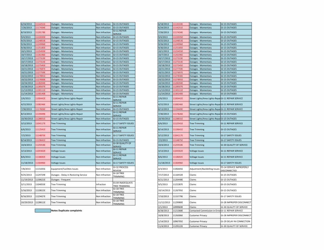
6/24/2013 1114251E Outages ‐ Momentary Non Infraction GI‐15 OUTAGES 6/18/2013 1113559E Outages ‐ Momentary GI‐15 OUTAGES7/26/2013 1117434E Outages ‐ Momentary Non Infraction GI‐15 OUTAGES 6/24/2013 1114251E Outages ‐ Momentary GI‐15 OUTAGES
8/19/2013 1120178E Outages ‐ Momentary Non InfractionGI‐11 REPAIR SERVICE
7/26/2013 1117434E Outages ‐ Momentary GI‐15 OUTAGES
9/4/2013 1122035E Outages ‐ Momentary Non Infraction GI‐15 OUTAGES 9/4/2013 1122035E Outages ‐ Momentary GI‐15 OUTAGES9/25/2013 1124853E Outages ‐ Momentary Non Infraction GI‐15 OUTAGES 9/25/2013 1124853E Outages ‐ Momentary GI‐15 OUTAGES9/26/2013 1124996E Outages ‐ Momentary Non Infraction GI‐15 OUTAGES 9/26/2013 1124996E Outages ‐ Momentary GI‐15 OUTAGES9/30/2013 1125185E Outages ‐ Momentary Non Infraction GI‐15 OUTAGES 9/30/2013 1125185E Outages ‐ Momentary GI‐15 OUTAGES10/1/2013 1125455E Outages ‐ Momentary Non Infraction GI‐15 OUTAGES 10/1/2013 1125455E Outages ‐ Momentary GI‐15 OUTAGES10/7/2013 1126196E Outages ‐ Momentary Non Infraction GI‐15 OUTAGES 10/7/2013 1126196E Outages ‐ Momentary GI‐15 OUTAGES10/17/2013 1127319E Outages ‐ Momentary Non Infraction GI‐15 OUTAGES 10/17/2013 1127319E Outages ‐ Momentary GI‐15 OUTAGES10/17/2013 1127314E Outages ‐ Momentary Non Infraction GI‐15 OUTAGES 10/17/2013 1127314E Outages ‐ Momentary GI‐15 OUTAGES10/18/2013 1127545E Outages ‐ Momentary Non Infraction GI‐15 OUTAGES 10/18/2013 1127545E Outages ‐ Momentary GI‐15 OUTAGES10/21/2013 1127697E Outages ‐ Momentary Non Infraction GI‐15 OUTAGES 10/21/2013 1127759E Outages ‐ Momentary GI‐15 OUTAGES10/21/2013 1127759E Outages ‐ Momentary Non Infraction GI‐15 OUTAGES 10/21/2013 1127697E Outages ‐ Momentary GI‐15 OUTAGES10/22/2013 1127891E Outages ‐ Momentary Non Infraction GI‐15 OUTAGES 10/22/2013 1127830E Outages ‐ Momentary GI‐15 OUTAGES10/22/2013 1127830E Outages ‐ Momentary Non Infraction GI‐15 OUTAGES 10/22/2013 1127891E Outages ‐ Momentary GI‐15 OUTAGES10/24/2013 1128204E Outages ‐ Momentary Non Infraction GI‐15 OUTAGES 10/24/2013 1128204E Outages ‐ Momentary GI‐15 OUTAGES10/28/2013 1128507E Outages ‐ Momentary Non Infraction GI‐15 OUTAGES 10/28/2013 1128507E Outages ‐ Momentary GI‐15 OUTAGES11/13/2013 1130111E Outages ‐ Momentary Non Infraction GI‐15 OUTAGES 11/13/2013 1130111E Outages ‐ Momentary GI‐15 OUTAGES11/14/2013 1130140E Outages ‐ Momentary Non Infraction GI‐15 OUTAGES 11/14/2013 1130140E Outages ‐ Momentary GI‐15 OUTAGES
2/6/2013 1100442E Street Lights/Area Lights‐Repair Non InfractionGI‐11 REPAIR SERVICE
2/6/2013 1100442E Street Lights/Area Lights‐Repai GI‐11 REPAIR SERVICE
4/22/2013 1108246E Street Lights/Area Lights‐Repair Non InfractionGI‐11 REPAIR SERVICE
4/22/2013 1108246E Street Lights/Area Lights‐Repai GI‐11 REPAIR SERVICE
7/30/2013 1117826E Street Lights/Area Lights‐Repair Non Infraction GI‐15 OUTAGES 8/13/2013 1119449E Street Lights/Area Lights‐Repai GI‐11 REPAIR SERVICE
8/13/2013 1119449E Street Lights/Area Lights‐Repair Non InfractionGI‐11 REPAIR SERVICE
7/30/2013 1117826E Street Lights/Area Lights‐Repai GI‐15 OUTAGES
10/30/2013 1128831E Street Lights/Area Lights‐Repair Non Infraction GI‐15 OUTAGES 10/30/2013 1128831E Street Lights/Area Lights‐Repai GI‐15 OUTAGES
3/12/2013 1104117E Tree Trimming Non Infraction GI‐17 SAFETY ISSUES 6/6/2013 1112541E Tree Trimming GI‐11 REPAIR SERVICE
6/6/2013 1112541E Tree Trimming Non InfractionGI‐11 REPAIR SERVICE
8/14/2013 1119641E Tree Trimming GI‐15 OUTAGES
7/2/2013 1114875E Tree Trimming Non Infraction GI‐17 SAFETY ISSUES 3/12/2013 1104117E Tree Trimming GI‐17 SAFETY ISSUES
8/14/2013 1119641E Tree Trimming Non Infraction GI‐15 OUTAGES 7/2/2013 1114875E Tree Trimming GI‐17 SAFETY ISSUES
10/4/2013 1125918E Tree Trimming Non InfractionGI‐30 QUALITY OF SERVICE
10/4/2013 1125918E Tree Trimming GI‐30 QUALITY OF SERVICE
3/13/2013 1104302E Voltage Issues Non InfractionGI‐11 REPAIR SERVICE
3/13/2013 1104302E Voltage Issues GI‐11 REPAIR SERVICE
8/6/2013 1118692E Voltage Issues Non InfractionGI‐11 REPAIR SERVICE
8/6/2013 1118692E Voltage Issues GI‐11 REPAIR SERVICE
11/18/2013 1130496E Voltage Issues Non Infraction GI‐17 SAFETY ISSUES 11/18/2013 1130496E Voltage Issues GI‐17 SAFETY ISSUES
7/8/2013 1115435E Equipment/Facilities Issues Non InfractionGI‐32 PROCESS REVIEW
4/3/2013 1106445E Adjustment/Backbilling IssuesES‐14 SERVICE IMPROPERLY DISCONNECTED
9/25/2013 1124724E Outages ‐ Delay in Restoring Service Non InfractionGI‐18 TREE TRIMMING
7/17/2013 1116432E Claims GI‐15 OUTAGES
11/19/2013 1130621E Outages ‐ Frequent 8/21/2013 1120448E Claims GI‐15 OUTAGES
3/11/2013 1104053E Tree Trimming InfractionES‐04 INADEQUATE TREE TRIMMING
9/5/2013 1122287E Claims GI‐15 OUTAGES
5/16/2013 1110615E Tree Trimming Non InfractionGI‐18 TREE TRIMMING
10/14/2013 1126795E Claims GI‐15 OUTAGES
9/16/2013 1123427E Tree Trimming Non InfractionGI‐18 TREE TRIMMING
7/10/2013 1115779E Claims GI‐17 SAFETY ISSUES
10/29/2013 1128611E Tree Trimming Non InfractionGI‐18 TREE TRIMMING
11/12/2013 1129980E Claims GI‐28 IMPROPER DISCONNECT
2/1/2013 1099969E Claims GI‐30 QUALITY OF SERVICENotes Duplicate complaints 8/28/2013 1121368E Contacted Commission in ErrorGI‐11 REPAIR SERVICE
10/8/2013 1126306E Customer Privacy GI‐28 IMPROPER DISCONNECT
1/14/2013 1096795E Customer Privacy GI‐29 DELAY IN CONNECTION
11/4/2013 1129122E Customer Privacy GI‐30 QUALITY OF SERVICE
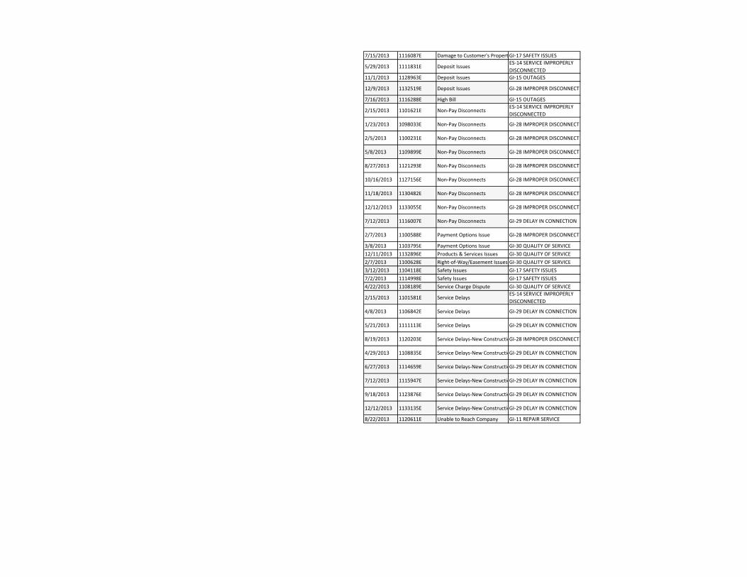
7/15/2013 1116087E Damage to Customer's Propert GI‐17 SAFETY ISSUES
5/29/2013 1111831E Deposit IssuesES‐14 SERVICE IMPROPERLY DISCONNECTED
11/1/2013 1128963E Deposit Issues GI‐15 OUTAGES
12/9/2013 1132519E Deposit Issues GI‐28 IMPROPER DISCONNECT
7/16/2013 1116288E High Bill GI‐15 OUTAGES
2/15/2013 1101621E Non‐Pay DisconnectsES‐14 SERVICE IMPROPERLY DISCONNECTED
1/23/2013 1098033E Non‐Pay Disconnects GI‐28 IMPROPER DISCONNECT
2/5/2013 1100231E Non‐Pay Disconnects GI‐28 IMPROPER DISCONNECT
5/8/2013 1109899E Non‐Pay Disconnects GI‐28 IMPROPER DISCONNECT
8/27/2013 1121293E Non‐Pay Disconnects GI‐28 IMPROPER DISCONNECT
10/16/2013 1127156E Non‐Pay Disconnects GI‐28 IMPROPER DISCONNECT
11/18/2013 1130482E Non‐Pay Disconnects GI‐28 IMPROPER DISCONNECT
12/12/2013 1133055E Non‐Pay Disconnects GI‐28 IMPROPER DISCONNECT
7/12/2013 1116007E Non‐Pay Disconnects GI‐29 DELAY IN CONNECTION
2/7/2013 1100588E Payment Options Issue GI‐28 IMPROPER DISCONNECT
3/8/2013 1103795E Payment Options Issue GI‐30 QUALITY OF SERVICE12/11/2013 1132896E Products & Services Issues GI‐30 QUALITY OF SERVICE2/7/2013 1100628E Right‐of‐Way/Easement Issues GI‐30 QUALITY OF SERVICE3/12/2013 1104118E Safety Issues GI‐17 SAFETY ISSUES7/2/2013 1114998E Safety Issues GI‐17 SAFETY ISSUES4/22/2013 1108189E Service Charge Dispute GI‐30 QUALITY OF SERVICE
2/15/2013 1101581E Service DelaysES‐14 SERVICE IMPROPERLY DISCONNECTED
4/8/2013 1106842E Service Delays GI‐29 DELAY IN CONNECTION
5/21/2013 1111113E Service Delays GI‐29 DELAY IN CONNECTION
8/19/2013 1120203E Service Delays‐New ConstructioGI‐28 IMPROPER DISCONNECT
4/29/2013 1108835E Service Delays‐New ConstructioGI‐29 DELAY IN CONNECTION
6/27/2013 1114659E Service Delays‐New ConstructioGI‐29 DELAY IN CONNECTION
7/12/2013 1115947E Service Delays‐New ConstructioGI‐29 DELAY IN CONNECTION
9/18/2013 1123876E Service Delays‐New ConstructioGI‐29 DELAY IN CONNECTION
12/12/2013 1133135E Service Delays‐New ConstructioGI‐29 DELAY IN CONNECTION
8/22/2013 1120611E Unable to Reach Company GI‐11 REPAIR SERVICE

ATTACHMENT I
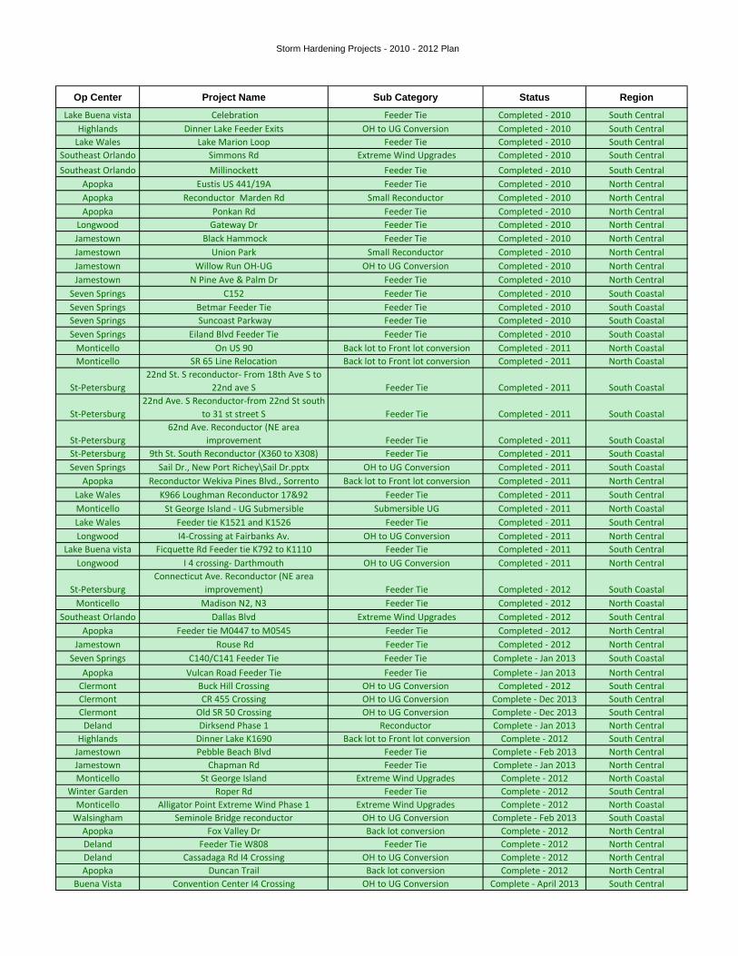
Storm Hardening Projects - 2010 - 2012 Plan
Op Center Project Name Sub Category Status Region
Lake Buena vista Celebration Feeder Tie Completed - 2010 South CentralHighlands Dinner Lake Feeder Exits OH to UG Conversion Completed - 2010 South Central
Lake Wales Lake Marion Loop Feeder Tie Completed - 2010 South CentralSoutheast Orlando Simmons Rd Extreme Wind Upgrades Completed - 2010 South CentralSoutheast Orlando Millinockett Feeder Tie Completed - 2010 South Central
Apopka Eustis US 441/19A Feeder Tie Completed - 2010 North CentralApopka Reconductor Marden Rd Small Reconductor Completed - 2010 North CentralApopka Ponkan Rd Feeder Tie Completed - 2010 North Central
Longwood Gateway Dr Feeder Tie Completed - 2010 North CentralJamestown Black Hammock Feeder Tie Completed - 2010 North CentralJamestown Union Park Small Reconductor Completed - 2010 North CentralJamestown Willow Run OH-UG OH to UG Conversion Completed - 2010 North CentralJamestown N Pine Ave & Palm Dr Feeder Tie Completed - 2010 North Central
Seven Springs C152 Feeder Tie Completed - 2010 South CoastalSeven Springs Betmar Feeder Tie Feeder Tie Completed - 2010 South CoastalSeven Springs Suncoast Parkway Feeder Tie Completed - 2010 South CoastalSeven Springs Eiland Blvd Feeder Tie Feeder Tie Completed - 2010 South Coastal
Monticello
On US 90 Back lot to Front lot conversion Completed - 2011 North CoastalMonticello SR 65 Line Relocation Back lot to Front lot conversion Completed - 2011 North Coastal
St-Petersburg22nd St. S reconductor- From 18th Ave S to
22nd ave S Feeder Tie Completed - 2011 South Coastal
St-Petersburg22nd Ave. S Reconductor-from 22nd St south
to 31 st street S Feeder Tie Completed - 2011 South Coastal
St-Petersburg62nd Ave. Reconductor (NE area
improvement Feeder Tie Completed - 2011 South CoastalSt-Petersburg 9th St. South Reconductor (X360 to X308) Feeder Tie Completed - 2011 South CoastalSeven Springs Sail Dr., New Port Richey\Sail Dr.pptx OH to UG Conversion Completed - 2011 South Coastal
Apopka Reconductor Wekiva Pines Blvd., Sorrento Back lot to Front lot conversion Completed - 2011 North CentralLake Wales K966 Loughman Reconductor 17&92 Feeder Tie Completed - 2011 South CentralMonticello St George Island - UG Submersible Submersible UG Completed - 2011 North CoastalLake Wales Feeder tie K1521 and K1526 Feeder Tie Completed - 2011 South CentralLongwood I4-Crossing at Fairbanks Av. OH to UG Conversion Completed - 2011 North Central
Lake Buena vista Ficquette Rd Feeder tie K792 to K1110 Feeder Tie Completed - 2011 South CentralLongwood I 4 crossing- Darthmouth OH to UG Conversion Completed - 2011 North Central
St-PetersburgConnecticut Ave. Reconductor (NE area
improvement) Feeder Tie Completed - 2012 South CoastalMonticello Madison N2, N3 Feeder Tie Completed - 2012 North Coastal
Southeast Orlando Dallas Blvd Extreme Wind Upgrades Completed - 2012 South CentralApopka Feeder tie M0447 to M0545 Feeder Tie Completed - 2012 North Central
Jamestown Rouse Rd Feeder Tie Completed - 2012 North CentralSeven Springs C140/C141 Feeder Tie Feeder Tie Complete - Jan 2013 South Coastal
Apopka Vulcan Road Feeder Tie Feeder Tie Complete - Jan 2013 North CentralClermont Buck Hill Crossing OH to UG Conversion Completed - 2012 South CentralClermont CR 455 Crossing OH to UG Conversion Complete - Dec 2013 South CentralClermont Old SR 50 Crossing OH to UG Conversion Complete - Dec 2013 South Central
Deland Dirksend Phase 1 Reconductor Complete - Jan 2013 North CentralHighlands Dinner Lake K1690 Back lot to Front lot conversion Complete - 2012 South Central
Jamestown Pebble Beach Blvd Feeder Tie Complete - Feb 2013 North CentralJamestown Chapman Rd Feeder Tie Complete - Jan 2013 North CentralMonticello St George Island Extreme Wind Upgrades Complete - 2012 North Coastal
Winter Garden Roper Rd Feeder Tie Complete - 2012 South CentralMonticello Alligator Point Extreme Wind Phase 1 Extreme Wind Upgrades Complete - 2012 North Coastal
Walsingham Seminole Bridge reconductor OH to UG Conversion Complete - Feb 2013 South CoastalApopka Fox Valley Dr Back lot conversion Complete - 2012 North CentralDeland Feeder Tie W808 Feeder Tie Complete - 2012 North CentralDeland Cassadaga Rd I4 Crossing OH to UG Conversion Complete - 2012 North CentralApopka Duncan Trail Back lot conversion Complete - 2012 North Central
Buena Vista Convention Center I4 Crossing OH to UG Conversion Complete - April 2013 South Central
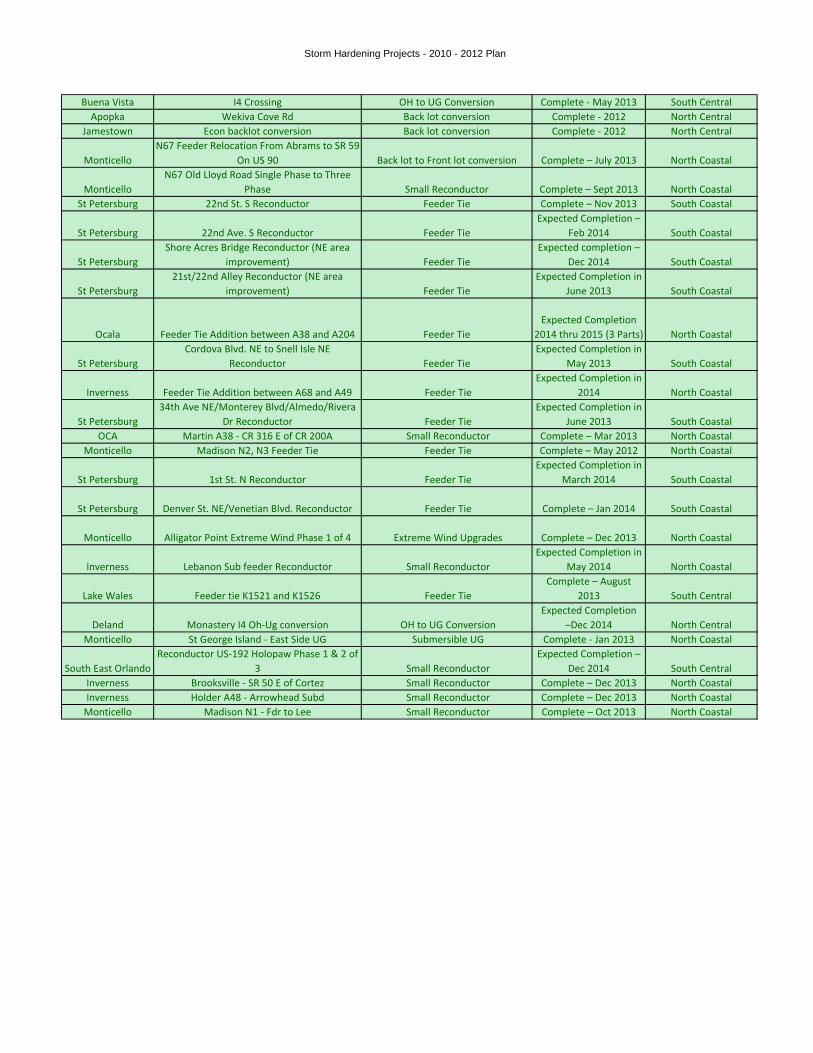
Storm Hardening Projects - 2010 - 2012 Plan
Buena Vista I4 Crossing OH to UG Conversion Complete - May 2013 South CentralApopka Wekiva Cove Rd Back lot conversion Complete - 2012 North Central
Jamestown Econ backlot conversion Back lot conversion Complete - 2012 North Central
MonticelloN67 Feeder Relocation From Abrams to SR 59
On US 90 Back lot to Front lot conversion Complete – July 2013 North Coastal
MonticelloN67 Old Lloyd Road Single Phase to Three
Phase Small Reconductor Complete – Sept 2013 North CoastalSt Petersburg 22nd St. S Reconductor Feeder Tie Complete – Nov 2013 South Coastal
St Petersburg 22nd Ave. S Reconductor Feeder TieExpected Completion –
Feb 2014 South Coastal
St PetersburgShore Acres Bridge Reconductor (NE area
improvement) Feeder TieExpected completion –
Dec 2014 South Coastal
St Petersburg21st/22nd Alley Reconductor (NE area
improvement) Feeder TieExpected Completion in
June 2013 South Coastal
Ocala Feeder Tie Addition between A38 and A204 Feeder TieExpected Completion
2014 thru 2015 (3 Parts) North Coastal
St PetersburgCordova Blvd. NE to Snell Isle NE
Reconductor Feeder TieExpected Completion in
May 2013 South Coastal
Inverness Feeder Tie Addition between A68 and A49 Feeder TieExpected Completion in
2014 North Coastal
St Petersburg34th Ave NE/Monterey Blvd/Almedo/Rivera
Dr Reconductor Feeder TieExpected Completion in
June 2013 South CoastalOCA Martin A38 - CR 316 E of CR 200A Small Reconductor Complete – Mar 2013 North Coastal
Monticello Madison N2, N3 Feeder Tie Feeder Tie Complete – May 2012 North Coastal
St Petersburg 1st St. N Reconductor Feeder TieExpected Completion in
March 2014 South Coastal
St Petersburg Denver St. NE/Venetian Blvd. Reconductor Feeder Tie Complete – Jan 2014 South Coastal
Monticello Alligator Point Extreme Wind Phase 1 of 4 Extreme Wind Upgrades Complete – Dec 2013 North Coastal
Inverness Lebanon Sub feeder Reconductor Small ReconductorExpected Completion in
May 2014 North Coastal
Lake Wales Feeder tie K1521 and K1526 Feeder TieComplete – August
2013 South Central
Deland Monastery I4 Oh-Ug conversion OH to UG ConversionExpected Completion
–Dec 2014 North CentralMonticello St George Island - East Side UG Submersible UG Complete - Jan 2013 North Coastal
South East OrlandoReconductor US-192 Holopaw Phase 1 & 2 of
3 Small ReconductorExpected Completion –
Dec 2014 South CentralInverness Brooksville - SR 50 E of Cortez Small Reconductor Complete – Dec 2013 North CoastalInverness Holder A48 - Arrowhead Subd Small Reconductor Complete – Dec 2013 North Coastal
Monticello Madison N1 - Fdr to Lee Small Reconductor Complete – Oct 2013 North Coastal

ATTACHMENT J
~~~~y~, DUKE
'~~.~ ~ ENERGY°
Storm Hardenin Plang
2013 - 2015
May 1, 2013
FPSC Rule 25-6.0342, F.A.C.
~~ DUKEENERGYmFLORIDA
Storm Hardening Plan May 1, 2013
I. Introduction:
Rule 25-6.0342, Florida Administrative Code, requires investor-owned electric utilities in
Florida to file a Storm Hardening Plan with the Florida Public Service Commission ("FPSC") on
or before May 7, 2007 and every three years thereafter as a matter of course. Rule 25-6.0342
specifies what must be included in utility storm hardening plans, and Duke Energy Florida, Inc.
("DEF") has tracked those rule provisions in its Storm Hardening Plan below:
25-6.0342(3): Each utility storm hardening plan shall contain a detailed description of the
construction standards, policies, and procedures employed to enhance the
reliability of overhead and underground electrical transmission and distribution
facilities.
DEF's construction standards, policies, practices, and procedures related to storm
hardening issues are listed below and are attached hereto as Attachment A:
Distribution OH Construction Manual
i. Cover page
1. Addresses NESC adherence standards.
ii. General Overhead section
1. Discusses company policy on extreme wind.
2. Details Florida's extreme wind contour lines.
3. Discusses the use of the Pole Foreman program.
iii. Poles, Guys and Anchors Section
1. Discusses DEF's standard pole stYengths, sizes, and limitations.
iv. Primary Construction section
1. Discusses corporate practices for primary line construction.
v. Coastal and Contaminated area section
1. Discusses corporate practices for primary line construction in
coastal areas.
1
~' DUKEENERGYFLORfDA
Storm Hardening Plan May 1, 2013
Distribution UG Construction Manual
vi. Cover page
1. Addresses NESC adherence standards.
vii. Underground General Section
1. Discusses location of UG facilities in accessible locations.
viii. OH-UG Transition section
1. Discusses corporate practices for primary framing on dip poles.
ix. Trenching and Conduit section
1. Discusses corporate practices for trenching and use of conduit on
primary UG circuits.
x. Flooding and Storm Surge Requirements
1. Discusses corporate pYocedures for the installation of UG
equipment in areas targeted for storm surge hardening.
Distribution Engineering Manual
xi. Overhead Design guide section
1. Addresses line location in accessible location.
2. Addresses NESC compliance.
3. Discusses Pole Foreman pYogram.
xii. Underground Design guide section
1. Addresses line location in accessible location.
2. Addresses NESC compliance.
Transmission -Extreme Wind Loadin Design Criteria Guideline for OverheadTransmission Line Structures
xiii. Standards Position Statement
1. Addresses NESC compliance.
2. Addresses American Society of Civil Engineer's Manual 74 (ACSE 74).
3. Discusses transmission line importance for reliability.
4. Details Florida's extreme wind contour lines.
/~ DUKEENERGYFLORIDA
Storm Hardening Plan May 1, 2013
Transmission -Line Engineerin~Desi~n Philosophy
xiv. Overhead Line Design philosophy
1. Addresses NESC compliance.
2. Addresses insulator loading criteria.
3. Addresses guy /anchor capacity ratings.
4. Addresses design load cases.
S. Addresses extreme wind guidelines.
6. Addresses structural guidelines.
Joint Use —Pole Attachment Guidelines and Clearances
xv. Pole Attachment Guidelines
1. Addresses Pole Attachment and Overlash Procedures.
2. Addresses Joint Use Construction.
3. Addresses Guys and Anchors.
xvi. Joint Use Clearances
1. Addresses Line Clearances.
2. Addresses Joint Use Clearances.
In addition to the standards, practices, policies, and procedures identified above, DEF'sWood Pole Inspection Plan, Vegetation Management Plan, and legacy Ongoing StormPreparedness Plan all contain standards, practices, policies, and procedures that address systemreliability and issues related to extreme weather events. These plans are included herewith asAttachment B.
25-6.0342(3)(a): Each filing shall, at a minimum, address the extent to which the utility's
storm hardening plan complies, at a minimum, with the National Electric
Safety Code that is applicable pursuant to subsection 25-6.0345(2), F.A.C.
All standards, practices, policies, and procedures in the manuals and plans listed above are
based on accepted industry practices designed to meet or exceed the requirements of the National
Electric Safety Code (NESC). These standards, practices, policies, and procedures are followed
on all new construction and all rebuilding and relocations of existing facilities.
3
~~ DUKEENERGYFLORIDA
Storm Hardening Plan May 1, 2013
25-6.0342(3)(b): Each filing shall, at a minimum, address the extent to which the utility's
storm hardening plan adopts the extreme wind loading standards specified
by Figure 250-2(d) of the 2007 edition of the NESC for new construction,
major planned work, and critical infrastructure.
New Construction:
With respect to new construction for transmission poles, DEF's transmission department
is building all new construction with either steel or concrete pole material. Virtually all new
transmission structures exceed a height of sixty feet above ground and therefore will be
constructed using the NESC Extreme Wind Loading criteria.
DEF's design standards can be summarized as: 1) quality construction in adherence with
current NESC requirements 2) well defined and consistently executed maintenance plans, and 3)
prudent end-of-life equipment replacement programs. When these elements are coupled with a
sound and practiced emergency response plan, construction grades as defined by the NESC
provide the best balance between cost and performance.
DEF has extensive experience with the performance of Grade C and Grade B
construction standards as defined by the NESC. That experience, which includes several
hurricane seasons and other severe weather events, indicates that properly constructed and
maintained distribution lines meeting all provisions of the NESC
perform satisfactorily and provide a prudent and responsible balance between cost and
performance.
DEF has not adopted extreme wind standards for all new distribution construction
because of the following reasons:
1. Section 250C of the 2012 version of the NESC does not call for the extreme wind
design standard for distribution poles which are less than sixty feet in height. Based
on the fact that DEF's distribution poles are less than sixty feet, the extreme wind
standard outlined in figure 250-2(d) does not apply.
~' DUKEENERGYFLORIDA
Storm Hardening Plan May 1, 2013
2. All credible research, which includes extensive studies by the NESC rules committee,
demonstrates that applying extreme winds standards would not benefit distribution
poles. See Exhibit 4 filed in Docket No. 060172-EU, August 31, 2006 Workshop.
3. Utility experience from around the country further indicates that electrical distribution
structures less than sixty feet in height are damaged in extreme wind events by trees,
tree limbs, and other flying debris. Thus, applying the extreme wind standard to
distribution poles would result in large increases in cost and design complexity
without a commensurate benefit.
4. DEF's experience was consistent with that of the other utilities around the nation who
found that vegetation and flying debris were the main causes of distribution pole
damage, a condition that the extreme wind standard will not address. In 2004,
approximately 96% of DEF's pole failures were attributable to flying debris and/or
super extreme wind events such as tornadoes and micro-bursts.
Major Manned work:
Consistent with NESC Rule 250C, DEF will use the extreme wind standard for all major
planned transmission work, including expansions, rebuilds, and relocations of existing facilities.
For the reasons discussed in the new construction section above, DEF has not adopted the
extreme wind standard for major planned distribution work, including expansions, rebuilds, or
relocations of existing facilities.
Critical infrastructure:
With respect to transmission, virtually all new transmission structures exceed a height of
sixty feet above ground and therefore are constructed using the NESC extreme wind loading
criteria. Accordingly, DEF will use the extreme wind standard for all major planned
transmission work, including expansions, rebuilds, and relocations of existing facilities,
irrespective of whether they can be classified as "critical" or "major."
DEF, for the reasons discussed in the new construction section above, has not adopted
the extreme wind standard for any of its distribution level critical infrastructure. Placing
~' DUKEENERGYFLaRiDA
Storm Hardening Plan May 1, 2013
distribution poles constructed to extreme wind standards around facilities such as hospitals and
police stations in DEF's service territory would unnecessarily increase costs and restoration time
if those poles are knocked down by falling trees or flying debris such as roofs or signs. DEF's
current level of construction, around critical facilities and around all other facilities, has
performed well during weather events and any pole failures due solely to wind impact were
caused by "super extreme" wind events such as tornados and "micro bursts," conditions that
would have caused and did cause extreme wind construction to fail as well.
While no current data or research supports the application of the extreme wind standard
to distribution pole construction, DEF continues to analyze the extreme wind standard by using
its prioritization model for implementation purposes in selected locations throughout DEF's
service territory. Since the submittal of the 2007 Storm Hardening plan, DEF constructed
several pilot projects using the extreme winds standards. To date, there has not been a significant
weather event that allowed DEF to assess the performance of these projects. In conjunction with
wind measuring devices, DEF will study the performance of the extreme wind standard at these
various sites when a weather event allows for such analysis. From this process, DEF expects to
continue to learn and adjust its extreme weather strategy based on information that it will collect
and gather from other utilities in Florida and throughout the nation as new standards and
applications are applied and tested.
25-6.0342(3)(c): Each filing shall, at a minimum, address the extent to which the utility's storm
hardening plan is designed to mitigate damage to underground and
supporting oveYhead transmission and distribution facilities due to flooding
and storm surges.
Based on DEF's experience in the 2004 and 2005 hurricane seasons, along with the
experiences of other utilities in Florida reported to the FPSC after those seasons, DEF has
concluded that underground applications may not be best suited for all areas. DEF has identified
areas in its service territory where current underground equipment should be replaced with
overhead due to the fact that those areas are subject to frequent and prolonged flooding resulting
in damage from water intrusion on underground equipment. Thus, one of DEF's most effective
tools in its hardening arsenal is to identify areas where underground equipment should and
D
~~ DUKEENERGYFLOR{DA
Storm Hardening Plan May 1, 2013
should not be used.
In axeas where underground equipment may be exposed to minor storm surge andlor
shorter term water intrusion, DEF has used its prioritization model (discussed in detail below) to
identify areas where certain mitigation projects will be put into place to test whether flood
mitigation techniques and devices can be used to protect equipment such as switchgears,
padmounted transformers and pedestals. In these selected project sites, DEF will test:
- Stainless steel equipment;
- Submersible connectors;
- Raised mounting boxes;
- Cold shrink sealing tubes; and
- Submersible secondary blocks.
Throughout the year after a significant weather event, DEF will monitor these
installations to collect and analyze data to determine how this equipment performs relative to
DEF's current design with respect to outage prevention, reduced maintenance, and reduced
restoration times. From this process, DEF will continue to learn and will adapt its flood and
storm surge strategies based on information that it will collect and based on the information
gathered by other utilities in Florida and throughout the nation as new standards and applications
are applied and tested.
St. George Island in Franklin County was one of the areas where DEF used its
submersible underground strategy to retrofit its existing facilities using the submersible standards
listed above. St George Island is a good example of an area that would be susceptible to surges
during a severe storm. The project was completed in 2007 and subsequent construction has
conformed to the design standard for areas susceptible to storm surge.
DEF also utilizes Geo Media software to determine the optimum location for submersible
underground facilities. The flood zones were provided by the state and overlaid onto DEF's land
base computer system along with other facilities. This method allows DEF to visually determine
which geographic areas would most benefit from submersible facilities. See example below.
7
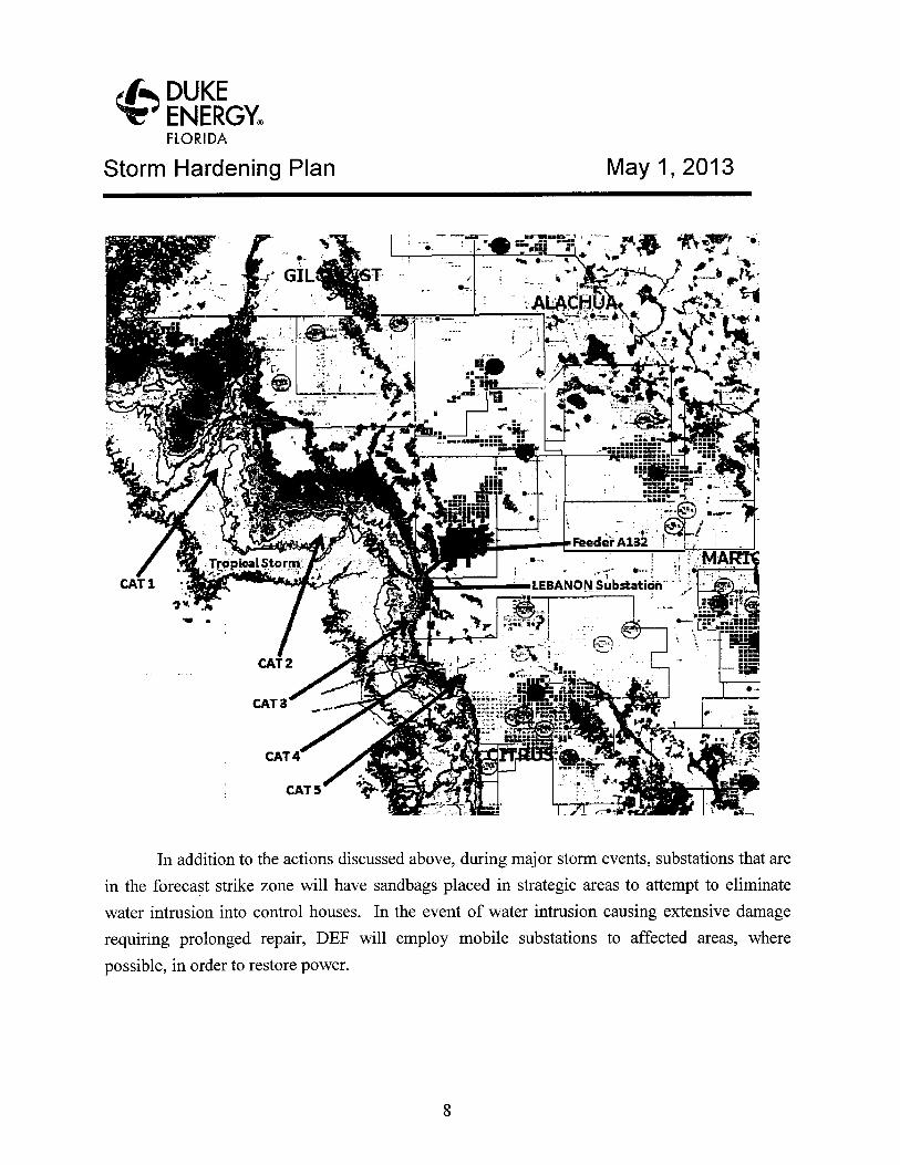
~' DUKEENERGYFLORIDA
Storm Hardening Plan May 1, 2013
In addition to the actions discussed above, during major storm events, substations that are
in the forecast strike zone will have sandbags placed in strategic areas to attempt to eliminate
water intrusion into control houses. In the event of water intrusion causing extensive damage
requiring prolonged repair, DEF will employ mobile substations to affected areas, where
possible, in order to restore power.
~' DUKEENERGYFLORIDA
Storm Hardening Plan May 1, 2013
25-6.0342(3)(d): Each filing shall, at a minimum, address the extent to which the utility's storm
hardening plan provides for the placement of new and replacement
distribution facilities so as to facilitate safe and efficient access for
installation and maintenance pursuant to Rule 25-6.0341, F.A.C.
DEF will continue to use front lot construction for all new distribution facilities and all
replacement distribution facilities unless a specific operational, safety, or other site-specific
reason exists for not using such construction at a given location. See Distribution Engineering
Manual, Section xv(1).
25-6.0342(4): Each utility stoYm hardening plan shall explain the systematic approach the
utility will follow to achieve the desired objectives of enhancing reliability and
reducing restoration costs and outage times associated with extreme weather
events.
As part of its systematic approach to storm hardening for the 2007-2009 Storm
Hardening plan, DEF engaged industry expert Davies Consulting ("DCI") in developing a
comprehensive prioritization model that has helped DEF identify potential hardening projects,
procedures, and strategies. DCI has worked with a number of utilities nationally to evaluate their
power delivery system major storm preparedness. They have also evaluated options for
infrastructure hardening to improve performance and reliability not only day-to-day, but also
during major storms. Collaborating with DCI, DEF created an evaluation framework for various
hardening options and prioritization of potential alternatives. Since 2007, the model has been
improved and enhanced to better reflect the changes in DEF's overall storm hardening strategy.
The structure of the model was adjusted to use more consistent scoring criteria to evaluate the
pilot projects. New software technology such as Geomedia was incorporated into the model. As
more data becomes available, DEF will continue to adjust its prioritization model as appropriate.
Using the same evaluation framework for the 2013-2015 Storm Hardening plan, DEF
prioritized its proposed projects based on various components that will be discussed in more
details below.
L~
~~ DUKEENERGYFLORIDA
Storm Hardening Plan May 1, 2013
Under the foregoing components of the evaluation framework, the prioritization model is
set up to analyze the following hardening alternatives for DEF:
o OH-to-UG Conversions
■ Taking existing overhead (OH) electric lines and facilities and placing
them underground (UG) via the use of specialized UG equipment and
materials. The primary purpose of this hardening activity is to attempt
to eliminate tree and debris related outages in the area of exposure.
When applied to crossings on major highways, this hardening activity
can also mitigate potential interference with first responders and other
emergency response personnel caused by fallen lines.
o Small Wire Upgrade
■ The conversion of an existing overhead line currently with either #4
AL or #6 Cu conductor to a thicker gauge conductor of 1 /0 or greater.
The primary purpose of this hardening activity is to attempt to utilize
stronger conductor that may be better able to resist breakage from
falling tree branches and debris.
o Backlot to Frontlot Conversion
■ Taking an existing overhead line located in the rear of a customer's
property and relocating it to the front of the customers property. This
involves the removal of the existing line in the rear of the property and
construction of a new line in the front of the property along with re-
routing service drops to individual customer meters. The primary
purpose of this hardening activity is to minimize the number of tree
exposures to the line to prevent outages and to expedite the restoration
process by allowing faster access in the event an outage occurs.
o Submersible UG
■ Taking an existing UG line and equipment and hardening it to
withstand a storm surge via the use of the current DEF storm surge
10
~~ DUKEENERGYmFLORIDA
Storm Hardening Plan May 1, 2013
standards. This involves the use of specialized stainless steel
equipment and submersible connections. The primary purpose of this
hardening activity is to attempt to minimize the damage caused by a
storm surge to the equipment and thus expedite the restoration after the
storm surge has receded.
o Alternative NESC Construction Standards
■ Building OH line and equipment segments to the extreme wind
standard as shown in the NESC extreme wind contour lines of figure
250-2(d). This will be done via the use of the current extreme wind
standards which call for the use of the industry accepted Pole Foreman
program to calculate the necessary changes. Typical changes include
shorter span lengths and higher class (stronger) poles. The primary
purpose of this hardening activity is to attempt to reduce the damage
caused by elevated winds during a major storm. Locations have been
chosen to provide contrasting performance data between open coastal
and inland heavily treed environments.
o Feeder ties
■ Tying radial feeders together to provide switching capabilities to
reduce outage duration. This hardening alternative will mitigate long
outages that would have otherwise occurred as a result of the inability
to transfer load/customers to an alternate source.
Although the concept of storm hardening is generally thought of as outage prevention, it
is inevitable that outages will still occur during a severe storm as a result of vegetation and flying
debris. Feeder ties will help mitigate the duration of such outages. Tying multiple feeders
together will give DEF the ability to minimize duration by serving customers from an alternate
source while repairs are being made on the affected segment. Based on DEF's experience in the
2004 -2005 hurricane seasons as well as more recent tropical storms, feeder ties are crucial for a
distribution system as it provides the opportunity to maximize the number of customers restored
in the shortest timeframe possible. Regardless of what caused the outage during a severe stone, a
11
~' DUKEENERGYFLQRIDA
Storm Hardening Plan May 1, 2013
radial feeder will be out for as long as it takes to make the necessary repairs. On the other hand,
a feeder tie would allow DEF to restore as many customers as possible, thereby minimizing the
number of customers that are without power for the length of the repair.
The development of the prioritization model begins with compiling a list of desired
projects submitted by engineers and field personnel most familiar with the specific region. Each
project is then evaluated based on the. following criteria:
o Major Storm Outage Reduction Impact
■ Determines the potential benefits that the project provides during a
major storm based on reduced damages or the ability to restore power
more rapidly.
o Community Storm Impact
■ Evaluates the potential benefits that the proposed project will have on
a community's ability to cope with damage.
o Third Party Impact
■ Captures complexities of proposed projects in terms of coordination
with third parties such as telecommunication, Cable TV, permitting,
easements, costs, etc.
o Overall Reliability
■ Captures the overall potential reliability benefits that the project
provides on a day to day basis in terms of reduced customer
interruptions and outage duration.
o Financial Cost
■ Provides the financial value of the proposed project based on cost per
customer and cost per foot of newly installed wire/cable.
The prioritization model is set up to address the following hardening project questions:
• How many customers are served from the upstream protective device?
• What will be the impact of this project on the restoration time during a
major storm?
• At what level of hurricane will the area served by this feeder flood due to
12
~' DUKEENERGYFLORIDA
Storm Hardening Plan May 1, 2013
storm surges?
• What is the tree density in the area served by this feeder or section?
• What level of tree damage will this project mitigate during a major storm?
• How many critical infrastructure components (lift stations, shelters,
hospitals, police, etc...) does this project address?
• How valuable will the project be perceived by the community?
• What are the major obstacles/risks for completing the project? i.e.
easements, permits, etc.
• What type of investment is required by joint users (telecoms and cable) to
complete this project?
• What is the 3-year average number of CEMI4 customers on this feeder?
• What is the 3-year average number of CMI on this feeder?
• What is the change in the annual CAIDI that this project will result in (on
the feeder or section)?
• Will this project reduce the number of momentary customer interruptions
on this section?
• What is the 3-year average number of CELID CI on this feeder?
• What is the construction Cost per customer
Each answer to the questions listed above is assigned a numerical value and subsequently
weighted to produce an overall rating for each specific hardening project. The prioritization
model is based on a structured methodology for evaluating the benefits associated with various
hardening options. The model allows for the ranking of the overall list of projects. It enables
DEF to strategically determine the order in which these projects are constructed, based on their
order of ranking.
DEF is using the prioritization model to ensure a systematic and analytical approach to
deploying storm hardening options within its service territory. For proven hardening options that
DEF is already using as part of its construction standards and policies, the prioritization model
will help DEF best locate and prioritize areas within its system where those options should be
used. For unproven or experimental hardening options, such as the extreme wind standard for
distribution pole construction, DEF is using its prioritization model to identify areas within its
13
~' DUKEENERGYFLORIDA
Storm Hardening Plan May 1, 2013
service territory where analytical data collection projects can be used to evaluate the
performance and results of such hardening options. Examples of specific projects that took place
between 2007 and 2012 are discussed later in this document.
25-6.0342(4)(a): A description of the facilities affected, including technical design
specifications, construction standards, and construction methodologies
employed.
All of DEF's facilities are affected to some degree by the standards, policies, procedures,
practices, and applications discussed throughout this document. Specific facilities are also
addressed herein in detail (i.e. upgrading all transmission poles to concrete and steel, using front
lot construction for all new distribution lines where possible). Technical design specifications,
construction standards, and construction methodologies are specifically discussed at pages 1
through 3 of this plan and are included in Attachments A and B.
25-6.0342(4)(b): The communities and areas within the utility's service area where the electric
infrastructure improvements are to be ~zade.
As discussed above, all of DEF's facilities are affected to some degree by the standards,
policies, procedures, practices, and applications discussed throughout this document. As a result,
all areas of DEF's service territory are impacted by DEF's storm hardening efforts. Based on
DEF's recent storm experience and/or through the prioritization model a number of projects were
identified, please see Attachment D for the Distribution Projects completed between 2007 and
2012.
14
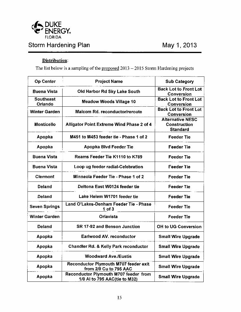
~~ DUKEENERGYFLORIDA
Storm Hardening Plan
Distribution:
May 1, 2013
The list below is a sampling of the proposed 2013 — 2015 Storm Hardening projects
Op Center Project Name Sub Category
Buena Vista Old Harbor Rd Sky Lake SouthBack Lot to Front Lot
ConversionSoutheast
Meadow Woods Village 10Back Lot to Front Lot
Orlando Conversion
Winter Garden Malcom Rd. reconductor/rerouteBack Lot to Front Lot
ConversionAlternative NESC
Monticello Alligator Point Extreme Wind Phase 2 of 4 ConstructionStandard
Apopka M451 to M453 feeder tie -Phase 1 of 2 Feeder Tie
Apopka Apopka Blvd Feeder Tie Feeder Tie
Buena Vista Reams Feeder Tie K1110 to K789 Feeder Tie
Buena Vista Loop ug feeder radial-Celebration Feeder Tie
Clermont Minneola Feeder Tie -Phase 1 of 2 Feeder Tie
Deland Deltona East W0124 feeder tie Feeder Tie
Deland Lake Helem W1701 feeder tie Feeder Tie
Seven SpringsLand O'Lakes-Denham Feeder Tie -Phase
Feeder Tie1 of 3
Winter Garden Orlavista Feeder Tie
Deland SR 17-92 and Benson Junction OH to UG Conversion
Apopka Earlwood AV. reconductor Small Wire Upgrade
Apopka Chandler Rd. ~ Kelly Park reconductor Small Wire Upgrade
Apopka Woodward Ave./Eustis Small Wire Upgrade
ApopkaReconductor Plymouth M707 feeder exit
Small Wire Upgradefrom 2/0 Cu to 795 AAC
ApopkaReconductor Plymouth M707 feeder from
Small Wire Upgrade1/0 AI to 795 AAC(tie to M32)
15
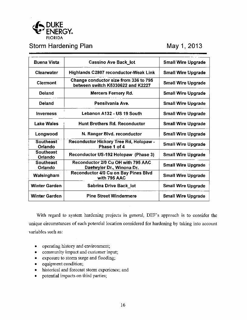
~' DUKEENERGYeFLORIDA
Storm Hardening Plan May 1, 2013
Buena Vista Cassino Ave Back_lot Small Wire Upgrade
Clearwater Highlands C2807 reconductor-Weak Link Small Wire Upgrade
ClermontChange conductor size from 336 to 795between switch K5330622 and K2227
Small Wire Upgrade
Deland Mercers Fernery Rd. Small Wire Upgrade
Deland Pensilvania Ave. Small Wire Upgrade
Inverness Lebanon A132 - US 19 South Small Wire Upgrade
Lake Wales Hunt Brothers Rd. Reconductor Small Wire Upgrade
Longwood N. Ranger Blvd. reconductor Small Wire Upgrade
SoutheastOrlando
Reconductor Hickory Tree Rd, Holopaw -Phase 1 of 4
Small Wire Upgrade
SoutheastOrlando
Reconductor US-192 Holopaw (Phase 3) Small Wire Upgrade
SoutheastOrlando
Reconductor 2/0 Cu OH with 795 AACDaetw ler Dr., Winona Dr.
Small Wire Upgrade
WalsinghamReconductor 410 Cu on Bay Pines Blvd
with 795 AACSmall Wire Upgrade
Winter Garden Sabrina Drive Back_lot Small Wire Upgrade
Winter Garden Pine Street Windermere Small Wire Upgrade
With regard to system hardening projects in general, DEF's approach is to consider the
unique circumstances of each potential location considered for hardening by taking into account
variables such as:
• operating history and environment;• community impact and customer input;• exposure to storm surge and flooding;• equipment condition;• historical and forecast storm experience; and• potential impacts on third parties;
16
~' DUKEENERGYFLORIDA
Storm Hardening Plan May 1, 2013
This surgical approach leads to the best solution for each discrete segment of the delivery
system.
For example, Pasadena Feeder X220 was selected as a storm hardening candidate for
2009. X220 is a mainly an overhead feeder along Pasadena Avenue running from the substation
south to the Palms of Pasadena Hospital. Engineering was initiated, and pole foreman was used
for pole size selection and pole spacing. It was calculated that a 100 foot spacing and pole
classes H1, 0, 1, and 2 would be required to meet the extreme wind loading criteria. Class H
poles are normally transmission poles, and have a large ground or butt circumference. The
general distribution guidelines for pole spacing are between 175 to 220 feet.
The Town of Pasadena was contacted by our Public Affairs Department, given the project
scope information, and was made aware of the positive impacts of the project. The city was
adamantly opposed to the storm hardening of X220 due to the larger class poles, closer pole
spacing, and the perceived overall aesthetic impact. Due to the overwhelming negative reaction
of the town, this project was cancelled. On the other hand, the San Blass Extreme wind project
in Monticello was well received by the community. The project was discussed with the County
Manager and the County Commissioner for the District. This project was also discussed with a
local civic club where many of the members were residents in the project area. This project was
completed in 2009. This is a real life example of why "one size does not fit all" when it comes
to storm hardening.
In areas like Gulf Boulevard and other coastal communities in Pinellas County, local
governments have worked with DEF to identify areas where overhead facilities have been or will
be placed underground, and this option will help to mitigate storm outages caused by vegetation
and flying debris. DEF is also working in these areas to evaluate upgrading portions of those
facilities to the surge-resistant design discussed above. Again, these hardening options may
work well in these communities, but may not be ideal or desirable in others.
Transmission:
The Transmission Department is employing asystem-based approach to changing out
wood poles to either concrete or steel poles based upon the inspection cycle and condition of
17
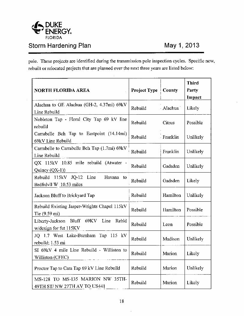
~~ DUKEENERGYFLORIDA
Storm Hardening Plan May 1, 2013
pole. These projects are identified during the transmission pole inspection cycles. Specific new,
rebuilt or relocated projects that are planned over the next three years are listed below:
Third
NORTH FLORIDA AREA Project Type County Party
Im act
Alachua to GE Alachua (GH-2, 4.37mi) 69kVRebuild Alachua Likely
Line Rebuild
Nobleton Tap -Floral City Tap 69 kV lineRebuild Citrus Possible
rebuild
Carrabelle Bch Tap to Eastpoint (14.14mi)Rebuild Franklin Unlikely
69kV Line Rebuild
Carrabelle to Carrabelle Bch Tap (1.7mi) 69kVRebuild Franklin Unlikely
Line Rebuild
QX 115kV 10.85 mile rebuild (Atwater -Rebuild Gadsden Unlikely
Quinc (QX-1 )
Rebuild 115kV JQ-12 Line Havana toRebuild Gadsden Likely
Brdfrdvll W 10.53 miles
Jackson Bluff to Brickyard Tap Rebuild Hamilton Unlikely
Rebuild Existing Jasper-Wrights Chapel 115kVRebuild Hamilton Possible
Tie (9.59 mi)
Liberty-Jackson Bluff 69KV Line RebldRebuild Leon Possible
w/desi n for fut 115KV
JQ 1.7 West Lake-Burnham Tap 115 kVRebuild Madison Unlikely
rebuild; 1.53 mi
SI 69kV 4 mile Line Rebuild -Williston toRebuild Marion Likely
Williston (CFEC)
Proctor Tap to Cara Tap 69 kV Line Rebuild Rebuild Marion Unlikely
MS-128 TO 1VIS-135 MARION NW 35TH-Rebuild Marion Likely
49TH ST/ NW 27TH AV TO US441
18
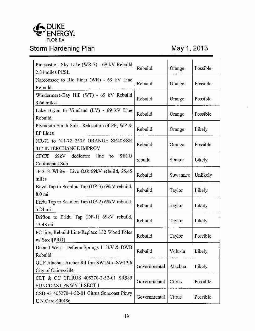
~~ DUKEENERGYFLORIDA
Storm Hardening Plan May 1, 2013
Pinecastle -Sky Lake (WR-7) - 69 kV RebuildRebuild Orange Possible
2.34 miles PCSL
Narcoossee to Rio Pinar (WR) - 69 kV LineRebuild Orange Possible
Rebuild
Windermere-Bay Hill (WT) - 69 kV RebuildRebuild Orange Possible
3.66 miles
Lake Bryan to Vineland (LV) - 69 kV LineRebuild Orange Possible
Rebuild
Plymouth South Sub -Relocation of PP, WP &Rebuild Orange Likely
EP Lines
NR-71 to NR-72 253F ORANGE SR408/SRRebuild Orange Possible
417 INTERCHANGE IMPROV
CFCX 69kV dedicated line to SECOrebuild Sumter Likely
Continental Sub
JF-3 Ft White -Live Oak 69kV rebuild, 25.45Rebuild Suwannee Unlikely
miles
Boyd Tap to Scanlon Tap (DP-3) 69kV rebuild,Rebuild Taylor Likely
8.0 mi
Eridu Tap to Scanlon Tap (DP-2) 69kV rebuild,Rebuild Taylor Likely
5.24 mi
Drifton to Eridu Tap (DP-1) 69kV rebuild,Rebuild Taylor Likely
13.48 mi
PC line; Rebuild Line-Replace 132 Wood PolesRebuild Taylor Possible
w/ Steel[PRG
Deland West -DeLeon Springs 115kV & DWBRebuild Volusia Likely
Rebuild
GUF Alachua Archer Rd frm S W 16th -S W 13thGovernmental Alachua Likely
Ci of Gainesville
CLT & CC CITRUS 405270-3-52-01 SR589Governmental Citrus Possible
SUNCOAST PKWY II-SECT 1
CSB-93 405270-4-52-01 Citrus Suncoast PkwyGovernmental Citrus Possible
II N.Card-CR486
19
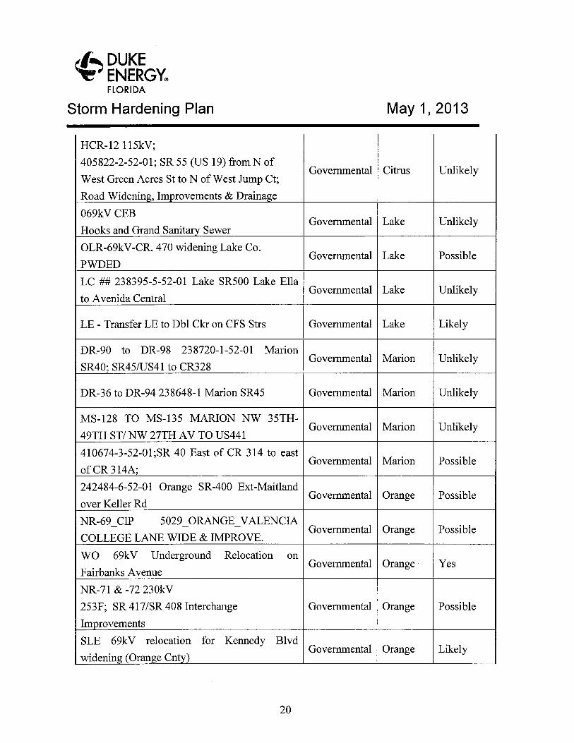
~~ DUKEENERGY°FLORIDA
Storm Hardening Plan May 1, 2013
HCR-12 115kV;
405822-2-52-01; SR 55 (US 19) from N ofGovernmental Citrus Unlikely
West Green Acres St to N of West Jump Ct;
Road Widenin , Im rovements & Draina e
069kV CEBGovernmental Lake Unlikely
Hooks and Grand Sanit Sewer
OLR-69kV-CR. 470 widening Lake Co.Governmental Lake Possible
PWDED
LC ## 238395-5-52-01 Lake SR500 Lake EllaGovernmental Lake Unlikely
to Avenida Central
LE -Transfer LE to Dbl Ckr on CFS Strs Governmental Lake Likely
DR-90 to DR-98 238720-1-52-01 MarionGovernmental Marion Unlikely
SR40; SR45/US41 to CR328
DR-36 to DR-94 238648-1 Marion SR45 Governmental Marion Unlikely
MS-128 TO MS-135 MARION NW 35TH-Governmental Marion Unlikely
49TH ST/ NW 27TH AV TO US441
410674-3-52-01;SR 40 East of CR 314 to eastGovernmental Marion Possible
of CR 314A;
242484-6-52-01 Orange SR-400 Ext-MaitlandGovernmental Orange Possible
over Keller Rd
NR-69 CIP 5029 ORANGE VALENCIAGovernmental Orange Possible
COLLEGE LANE WIDE &IMPROVE.
WO 69kV Underground Relocation onGovernmental Orange Yes
Fairbanks Avenue
NR-71 & -72 230kV
253F; SR 417/SR 408 Interchange Governmental Orange Possible
Im rovements
SLE 69kV relocation for Kennedy BlvdGovernmental Orange Likely
widenin (Oran e Cnt )
20
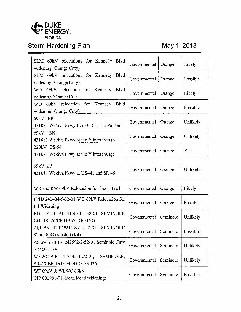
~' DUKEENERGYF~o~i~a
Storm Hardening Plan May 1, 2013
SLM 69kV relocations for Kennedy BlvdGovernmental Orange Likely
widenin (Oran e Cnty
SLM 69kV relocations for Kennedy BlvdGovernmental Orange Possible
widenin (Oran e Cnt )
WO 69kV relocation for Kennedy BlvdGovernmental Orange Likely
widenin (Oran e Cnty)
WO 69kV relocation for Kennedy BlvdGovernmental Orange Possible
widenin (Oran e Cnt
69kV EPGovernm;,ntal Orange Unlikely
431081 Wekiva Pk from US 441 to Ponkan
69kV BKGovernmental Orange Unlikely
431081 Wekiva Pkwy at the Y interchan e
230kV PS-94Governmental Orange Yes
431081 Wekiva Pk at the Y interchan e
69kV EPGovernmental Orange Unlikely
431081 Wekiva Pkwy at US441 and SR 46
WR and RW 69kV Relocation for Econ Trail Governmental Orange Likely
FPID 242484-5-32-01 WO 69kV Relocation forGovernmental Orange Possible
I-4 Widenin
FTO FTO-141 415030-1-38-01 SEMINOLEGovernmental Seminole Unlikely
CO. SR426/CR419 WIDENING
ASL-58 FPID#242592-3-32-01 SEMINOLEGovernmental Seminole Possible
STATE ROAD 400 (I-4)
ASW-17,18,19 242592-2-52-01 Seminole CntyGovernmental Seminole Unlikely
SR400 / I-4
WEWC-WF 417545-1-52-01, SEMINOLE,Governmental Seminole Unlikely
SR417 BRIDGE MOD SR426
WF 69kV & WEWC 69kVGovernmental Seminole Possible
CIP 001981-01; Dean Road widenin ;
21
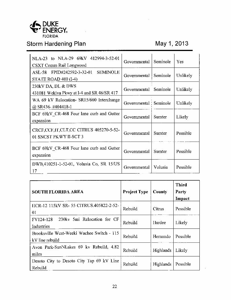
~~ DUKEENERGYFLORIDA
Storm Hardening Plan May 1, 2013
NLA-23 to NLA-29 69kV 412994-3-52-01Governmental Seminole Yes
CSXT Comm Rail Lon wood
ASL-58 FPID#242592-3-32-01 SEMINOLEGovernmental Seminole Unlikely
STATE ROAD 400 (I-4
230kV DA, DL & DWSGovernmental Seminole Unlikely
431081 Wekiva Pk at I-4 and SR 46/SR 417
WA 69 kV Relocation- SR15/600 InterchangeGovernmental Seminole Unlikely
SR436- #404418-1
BCF 69kV CR-468 Four lane curb and GutterGovernmental Sumter Likely
ex ansion
CRCF,CCF,IT,CLT,CC CITRUS 405270-5-52-Governmental Sumter Possible
O1 SNCST PKWY II-SCT 3
BCF 69kV CR-468 Four lane curb and GutterGovernmental Sumter Possible
expansion
DWB,410251-1-52-01, Volusia Co, SR 15/USGovernmental Volusia Possible
17
Third
SOUTH FLORIDA AREA Project Type County Party
Im act
HCR-12 115kV SR- 55 CITRUS.405822-2-52-Rebuild Citrus Possible
O1
FV124-128 230kv Smi Relocation for CFRebuild Hardee Likely
Industries
Brooksville West-Weeki Wachee Switch - 115Rebuild Hernando Possible
kV line rebuild
Avon Park-SunNLakes 69 kv Rebuild, 4.82Rebuild Highlands Likely
miles
Desoto City to Desoto City Tap 69 kV LineRebuild Highlands Possible
Rebuild
22
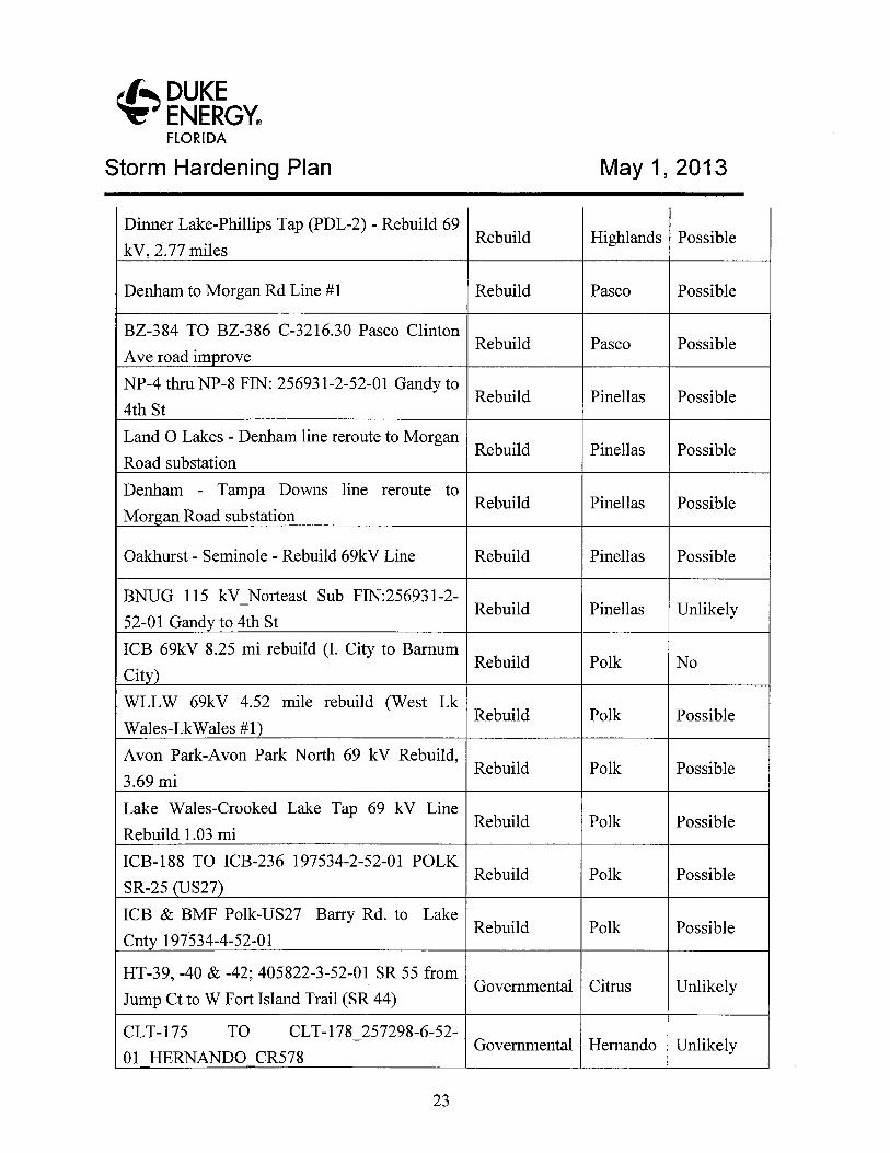
~' DUKEENERGY°FLORIDA
Storm Hardening Plan May 1, 2013
Dinner Lake-Phillips Tap (PDL-2) -Rebuild 69Rebuild Highlands Possible
kV, 2.77 miles
Denham to Morgan Rd Line #1 Rebuild Pasco Possible
BZ-384 TO BZ-386 C-3216.30 Pasco ClintonRebuild Pasco Possible
Ave road im rove
NP-4 thru NP-8 FIN: 256931-2-52-01 Gandy toRebuild Pinellas Possible
4th St
Land OLakes -Denham line reroute to MorganRebuild Pinellas Possible
Road substation
Denham - Tampa Downs line reroute toRebuild Pinellas Possible
Mor an Road substation
Oakhurst -Seminole -Rebuild 69kV Line Rebuild Pinellas Possible
BNUG 115 kV Norteast Sub FIN:256931-2-Rebuild Pinellas Unlikely
52-01 Gand to 4th St
ICB 69kV 8.25 mi rebuild (I. City to BarnumRebuild Polk No
City)
WLLW 69kV 4.52 mile rebuild (West LkRebuild Polk Possible
Wales-LkWales #1)
Avon Park-Avon Park North 69 kV Rebuild,Rebuild Polk Possible
3.69 mi
Lake Wales-Crooked Lake Tap 69 kV LineRebuild Polk Possible
Rebuild 1.03 mi
ICB-188 TO ICB-236 197534-2-52-01 POLKRebuild Polk Possible
SR-25 US27)
ICB & BMF Polk-US27 Barry Rd. to LakeRebuild Polk Possible
Cnt 197534-4-52-01
HT-39, -40 & -42; 405822-3-52-01 SR 55 fromGovernmental Citrus Unlikely
Jump Ct to W Fort Island Trail (SR 44)
CLT-175 TO CLT-178 257298-6-52-Governmental Hernando Unlikely
01 HERNANDO CR578
23
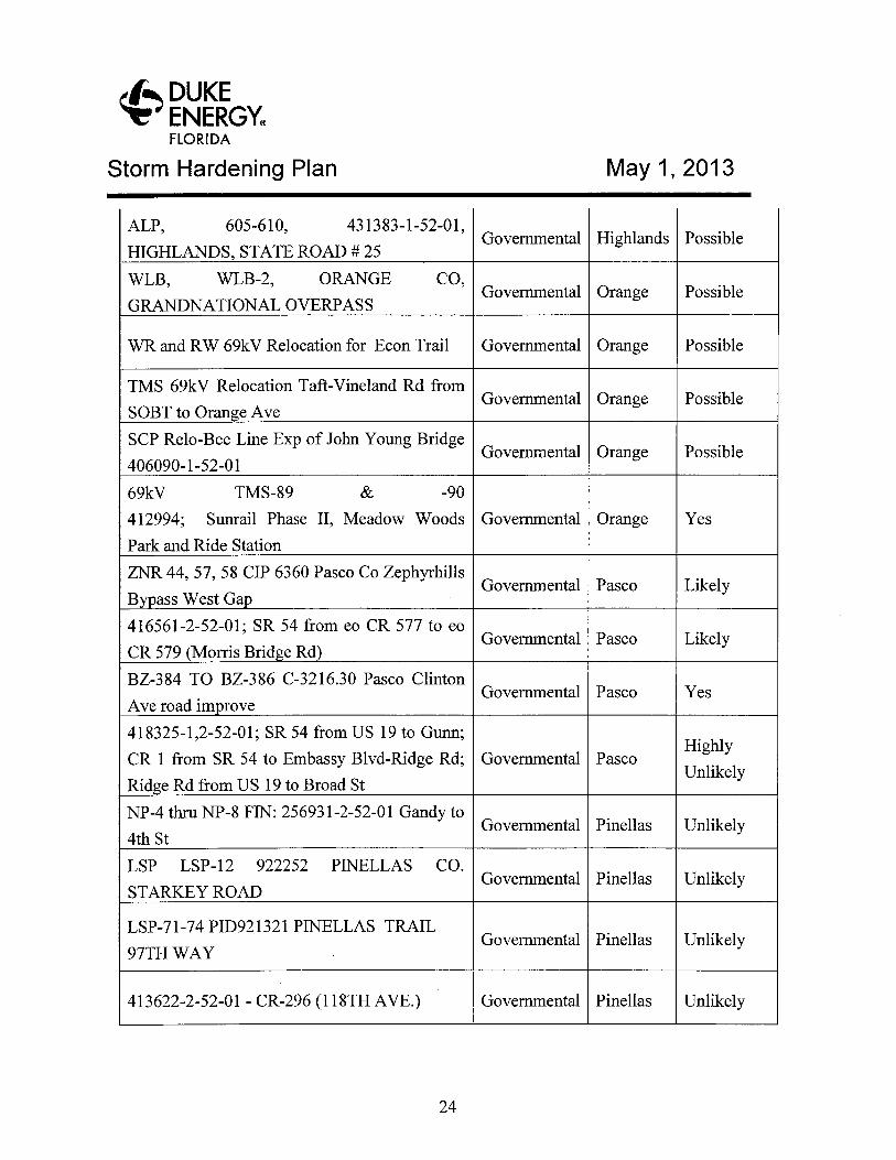
~' DUKEENERGYFLORIDA
Storm Hardening Plan May 1, 2013
ALP, 605-610, 431383-1-52-01,Governmental Highlands Possible
HIGHLANDS, STATE ROAD # 25
WLB, WLB-2, ORANGE CO,Governmental Orange Possible
GRANDNATIONAL OVERPASS
WR and RW 69kV Relocation for Econ Trail Governmental Orange Possible
TMS 69kV Relocation Taft-Vineland Rd fromGovernmental Orange Possible
SOBT to Oran e Ave
SCP Relo-Bee Line Exp of John Young BridgeGovernmental Orange Possible
406090-1-52-01
69kV TMS-89 & -90
412994; Sunrail Phase II, Meadow Woods Governmental Orange Yes
Park and Ride Station
ZNR 44, 57, 58 CIP 6360 Pasco Co ZephyrhillsGovernmental Pasco Likely
B ass West Ga
416561-2-52-01; SR 54 from eo CR 577 to eoGovernmental Pasco Likely
CR 579 (Morris Brid e Rd
BZ-384 TO BZ-386 C-3216.30 Pasco ClintonGovernmental Pasco Yes
Ave road im rove
418325-1,2-52-01; SR 54 from US 19 to Gunn;Highly
CR 1 from SR 54 to Embassy Blvd-Ridge Rd; Governmental PascoUnlikely
Rid e Rd from US 19 to Broad St
NP-4 thru NP-8 FIN: 256931-2-52-01 Gandy toGovernmental Pinellas Unlikely
4th St
LSP LSP-12 922252 PINELLAS CO.Governmental Pinellas Unlikely
STARKEY ROAD
LSP-71-74 PID921321 PINELLAS TRAILGovernmental Pinellas Unlikely
97TH WAY
413622-2-52-01 - CR-296 (118TH AVE.) Governmental Pinellas Unlikely
24
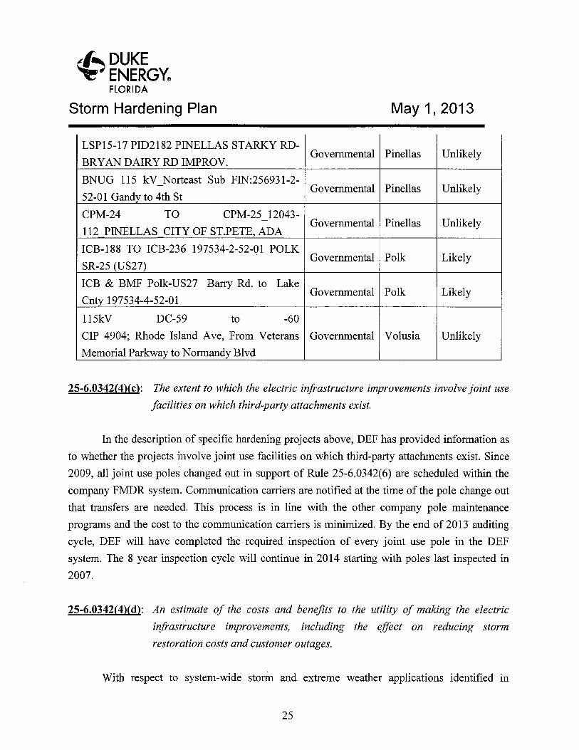
~~ DUKEENERGYFl~RIDA
Storm Hardening Plan May 1, 2013
LSP15-17 PID2182 PINELLAS STARKY RD-Governmental Pinellas Unlikely
BRYAN DAIRY RD IMPROV.
BNUG 115 kV Norteast Sub FIN:256931-2-Governmental Pinellas Unlikely
52-01 Gand to 4th St
CPM-24 TO CPM-25 12043-Governmental Pinellas Unlikely
112 PINELLAS CITY OF ST.PETE, ADA
ICB-188 TO ICB-236 197534-2-52-01 POLKGovernmental Polk Likely
SR-25 (US27
ICB & BMF Polk-US27 Barry Rd. to LakeGovernmental Polk Likely
Cnt 197534-4-52-01
115kV DC-59 to -60
CIP 4904;' Rhode Island Ave, From Veterans Governmental Volusia Unlikely
Memorial Parkway to Normandy Blvd
25-6.0342(4)(c): The extent to which the electric infrastructure improvements involve joint use
facilities on which third party attachments exist.
In the description of specific hardening projects above, DEF has provided information as
to whether the projects involve joint use facilities on which third-party attachments exist. Since
2009, all joint use poles changed out in support of Rule 25-6.0342(6) are scheduled within the
company FMDR system. Communication carriers are notified at the time of the pole change out
that transfers are needed. This process is in line with the other company pole maintenance
programs and the cost to the communication carriers is minimized. By the end of 2013 auditing
cycle, DEF will have completed the required inspection of every joint use pole in the DEF
system. The 8 year inspection cycle will continue in 2014 starting with poles last inspected in
2007.
25-6.0342(4)(d): An estimate of the costs and benefits to the utility of making the electric
infrastructure improvements, including the effect on reducing storm
restoration costs and customer outages.
With respect to system-wide storm and extreme weather applications identified in
25
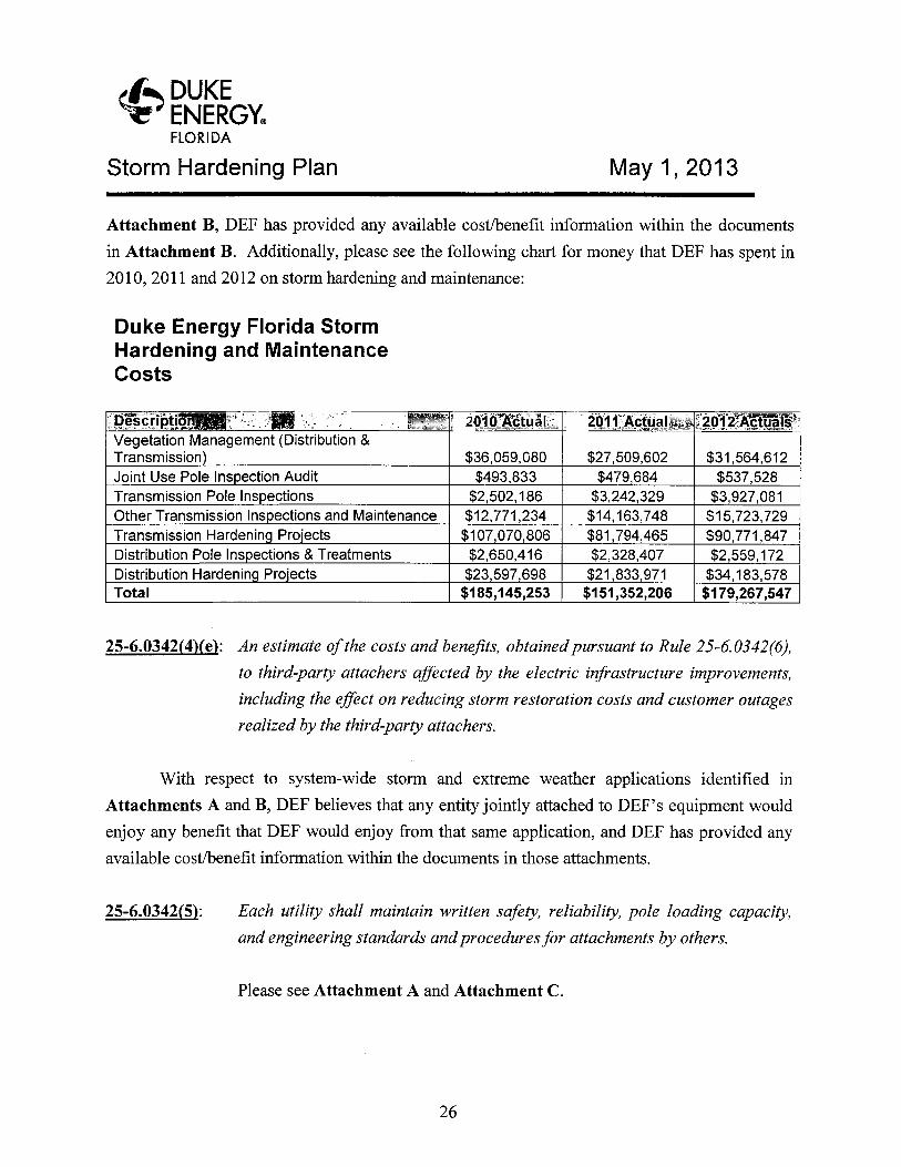
~~ DUKEENERGYFLQRl~A
Storm Hardening Plan May 1, 2013
Attachment B, DEF has provided any available cost/benefit information within the documents
in Attachment B. Additionally, please see the following chart for money that DEF has spent in
2010, 2011 and 2012 on storm hardening and maintenance:
Duke Energy Florida StormHardening and MaintenanceCosts
pescripti .' ' ~:~ ~~'' ' , _ . ' ~ 2b10 Actual ,= 2071; Actual._ ~ 2012`Actuals .Vegetation Management (Distribution &Transmission $36,059,G80 $27,509,602 $31,564,612Joint Use Pole Ins ection Audit $493,833 $479,684 $537,528Transmission Pole Ins ections $2,502,186 $3,242,329 $3,927,081Other Transmission Ins ections and Maintenance $12,771,234 $14,163,748 $15,723,729Transmission Hardenin Pro~ects $107,070,806 $81,794,465 $90,771,847Distribution Pole Ins ections &Treatments $2,650,416 $2,328,407 $2,559,172Distribution Hardenin Pro'ects $23,597,698 $21,833,971 $34,183,578Total $185,145,253 $151,352,206 $179,267,547
25-6.0342(4)(e): An estimate of the costs and benefits, obtained pursuant to Rule 25-6.0342(6),
to third party attachers affected by the electric infrastructure improvements,
including the effect on reducing storm restoration costs and customer outages
realized by the third-party attackers.
With respect to system-wide storm and extreme weather applications identified in
Attachments A and B, DEF believes that any entity jointly attached to DEF's equipment would
enjoy any benefit that DEF would enjoy from that same application, and DEF has provided any
available cost/benefit information within the documents in those attachments.
25-6.0342(5): Each utility shall maintain written safety, reliability, pole loading capacity,
and engineering standards and procedures for attachments by others.
Please see Attachment A and Attachment C.
d.
-~' DUKEENERGYFLORIDA
Storm Hardening Plan May 1, 2013
25-6.0342(5): The attachment standards and procedures shall meet or exceed the NESC so
as to assure that third party facilities do not impair electric safety, adequacy,
or pole reliability; do not exceed pole loading capacity; and are constructed,
installed, maintained, and operated in accordance with generally accepted
engineering practices for the utility's service territory.
All third-party joint use attachments on DEF's distribution and transmission poles are
engineered and designed to meet or exceed current NESC clearance and wind loading standards.
New attachment requests are field inspected before and after attachments to assure company
construction standards are being met. All entities proposing to attach joint use attachments to
DEF's distribution and transmission poles are given a copy of the company-prepared "Joint Use
Attachment Guidelines." Attached hereto as Attachment C. These guidelines are a
comprehensive collection of information spelling out the company's joint use process,
construction standards, timelines, financial responsibilities, and key company contacts
responsible for the completing permit requests. All newly proposed joint use attachments are
field checked and designed using generally accepted engineering practices to assure the new
attachments do not overload the pole or impact safety or reliability of the electric or other
attachments. Additionally, annual and full-system audits are performed as detailed in DEF's
annual March 1 comprehensive reliability report. For details on this activity, please see
Attachment B.
25-6.0342(6): Each utility shall seek input from and attempt in good faith to accommodate
concerns raised by other entities with existing agreements to share the use of
its electric facilities.
Since 2009, DEF has continued to communicate with the teleconununications carriers
regarding the pole loading project. DEF has diligently cut cost for carriers by suggesting make
ready solutions for over loaded pole conditions that do not include pole change outs. Additional
guying and attachment rearrangement solutions have saved the communications carriers
thousands of dollars annually. DEF continues to answer any questions and address concerns
expressed verbally by joint attachers. DEF has taken all input received into consideration in the
development and finalization of this storm hardening plan.
27
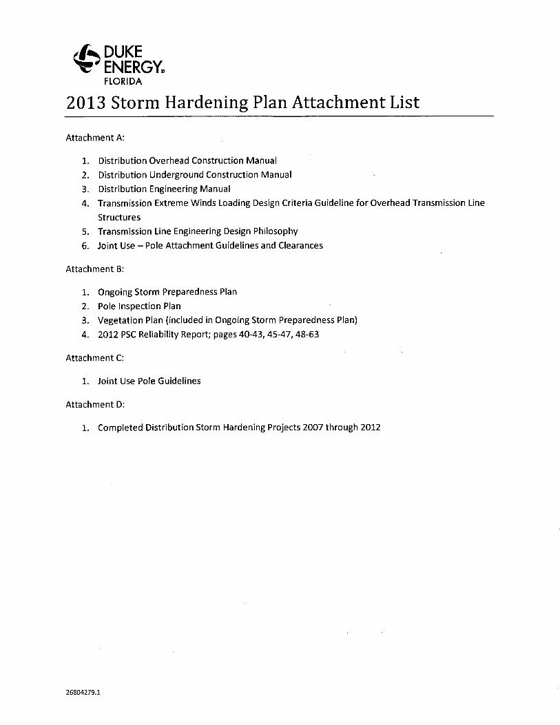
~~ DUKEENERGYFLORIDA
2013 Storm Hardening Plan Attachment List
Attachment A:
1. Distribution Overhead Construction Manual
2. Distribution Underground Construction Manual
3. Distribution Engineering Manual
4. Transmission Extreme Winds Loading Design Criteria Guideline for Overhead Transmission Line
Structures
5. Transmission Line Engineering Design Philosophy
6. Joint Use —Pole Attachment Guidelines and Clearances
Attachment B:
1. Ongoing Storm Preparedness Plan
2. Pole Inspection Plan
3. Vegetation Plan (included in Ongoing Storm Preparedness Plan)
4. 2012 PSC Reliability Report; pages 40-43, 45-47, 48-63
Attachment C:
1. Joint Use Pole Guidelines
Attachment D:
1. Completed Distribution Storm Hardening Projects 2007 through 2012
26804279.1

ATTACHMENT K

Comprehensive Wood Pole Inspection Plan
1
Purpose and Intent of the Plan: To implement and update a wood pole inspection program that complies with FPSC Order No. PSC-06-0144-PAA-EI issued February 27, 2006 (the “Plan”). The Plan1 concerns inspection of wooden transmission and distribution poles, as well as pole inspections for strength requirements related to pole attachments. The Plan is based on the requirements of the National Electric Safety Code (“NESC”) and an average eight-year inspection cycle. The Plan provides a detailed program for gathering pole-specific data, pole inspection enforcement, co-located pole inspection, and estimated program funding. This Plan also sets forth pole inspection standards utilized by Duke Energy Florida (“DEF”) that meet or exceed the requirements of the NESC. The Plan includes the following specific sub-plans: •Transmission Wood Pole Inspection Plan (“Transmission Plan”). •Distribution Wood Pole Inspection Plan (“Distribution Plan”). •Joint Use Wood Pole Inspection Plan (“Joint Use Plan”). These three inspection sub-plans are outlined and described below. All of these sub-plans will be evaluated on an ongoing basis to address trends, external factors beyond the Company’s control (such as storms and other weather events), and cost effectiveness.
1) Transmission Wood Pole Inspection Plan A. Introduction Ground-line inspection and treatment programs detect and treat decay and mechanical damage of in-service wood poles. DEF’s Transmission Department accomplishes this by identifying poles that are 8 years of age or older and treating these poles as necessary in order to extend their useful life. As required, DEF also assesses poles and structures for incremental attachments that may create additional loads. Poles that can no longer maintain the safety margins required by the NESC (ANSI C2-2002) will be remediated. These inspections result in one of four or a combination of the following actions: (1) No action required; (2) Application of treatment; (3) Repaired; (4) Replaced. B. General Plan Provisions (i). Pole Inspection Selection Criteria 1 The 2012 Comprehensive Wood Pole Inspection Plan was provided to the Commission by DEF’s predecessor, Progress Energy Florida, Inc. (“PEF”) per Order No. PSC-06-0144-PAA-EI. DEF confirms there are no substantive changes to the Plan.
Comprehensive Wood Pole Inspection Plan
2
Transmission performs ground patrols to inspect transmission system line assets to allow for the planning, scheduling, and prioritization of corrective and preventative maintenance work. These patrols assess the overall condition of the assets including insulators, connections, grounding, and signs, as well as an assessment of pole integrity. These patrols are be done on a three-year cycle and the assessment data and reports generated from these patrols are used to plan the ground-line inspections set forth in Section 1B(ii) below. The ground patrol inspections categorize wood poles into four conditions or states (State 2-5). DEF conducts ground-line inspections of State 2 and 3 poles. State 3 poles are given priority for ground-line inspection scheduling. DEF replaces State 4 and 5 poles. DEF no longer utilizes the State 1 category. In performing inspection and patrols, the following Transmission Line Wood Poles Inspection State Categories shall apply: State 2 : Meeting all of the criteria listed below: • No woodpecker holes or woodpecker holes have been repaired. • A pole that has been cut and capped. • Checks/cracks show no decay or insect damage. • Ground-line inspected/treated with no data in the remarks field of the report and no noted reduction in effective pole diameter. • Hammer test indicates a hard pole. • No pole top deflection noted. State 3 : Meeting one or more of the criteria listed below: • Checks/cracks show decay or insect damage, or the presence of minimal shell cracking. • Ground-line inspected/treated with decay noted in the remarks field of the report and a noted reduction in effective pole diameter. • Hammer test indicates a minimal amount of ground-line decay. • Pole has been repaired (e.g., C-truss). • Poles with a wood bayonet or a pole that needs to be cut and capped. • Pole can be partially hollow but with no less than 3 – 4 inches of shell thickness and cannot be caved during a hammer test. • Pole top deflection is less than 3 feet. State 4 : Meeting one or more of the criteria listed below and should be scheduled to be replaced: • Woodpecker holes which have deep cavities and are not repairable. • Checks/cracks show significant decay or insect damage, or the presence of substantial shell cracking. • Decay in the pole top is extensive such that the pole cannot be cut and capped nor is the pole top section a candidate for a bayonet. • Ground-line inspected/treated and identified as rejected/restorable or rejected/non-restorable.

Comprehensive Wood Pole Inspection Plan
3
• When hammer tested, ground-line decay pockets are found and are greater than 5 inches wide and 2 inches deep. • Pole is hollow with less than 3 – 4 inches of shell thickness extending over more than one-quarter of the pole circumference, determined by hammer test and/or a screw driver. • Pole top deflection is between 3 to 5 feet. State 5 : Meeting one or more of the criteria listed below. (This pole should be scheduled to be replaced as soon as possible): • Woodpecker holes which have deep cavities and are not repairable, severely affecting the integrity of the pole. • Ground-line inspection indicates the pole as “priority.” • When hammer tested, ground-line decay pockets are found and are greater than 8 inches wide by 3 inches deep. • Pole is hollow with less than 2 inches of shell thickness extending over more than one-third of the pole circumference. • Pole deflection exceeds 5 feet. (ii). Ground-Line Inspections Ground-line inspections of wood transmission poles are conducted by qualified pole inspectors on an average 8-year cycle. This results in, on average, approximately 12.5% of the remaining population of wood poles receiving this type of inspection on an annual basis. Treatment and inspection work shall be done or supervised by a foreman with a minimum of six months experience and shall be certified as being qualified for this work. For poles without an existing inspection hole, the pole will be bored at a 45 degree angle below the ground line to a depth that extends past the center of the pole. For previously inspected poles, the original ground-line inspection plug shall be bored out and the depth of the inspection hole measured to ensure that the pole has been bored to the required depth. Treatment application plug(s) will be bored out and the depth of these holes measured to ensure compliance. Hammer marks should be evident to show that the pole has been adequately sounded. All work done, materials used, and materials disposed of shall be in compliance and accordance with all local, municipal, county, state, and federal laws and regulations applicable to said work. Preservatives used shall conform to the minimum requirements as set forth in this Transmission Plan. The inspection method used is a sound and bore inspection that will include the following components: • Above Ground Observations - Visual inspection of the exterior condition of the pole and visual
inspection of components hanging from the pole.

Comprehensive Wood Pole Inspection Plan
4
• Sound with Hammer – The exterior of the pole is tested with a hammer and the inspector listens for “hollowness” of the pole.
• Bore at Ground Line – The pole is bored at a 45 degree angle below the ground line. This inspection method helps to determine internal decay at the base as well as measure the amount of “good wood” left on the interior of the pole.
• Excavate to 18 inches (Full Ground Line Inspection) – The soil is removed 18 inches below ground line. Decay pockets are identified and bored to determine the extent of decay.
• Removal of Surface Decay – Identified areas of decay are removed down to “good wood” using a sharp pick.
• Assessment of Remaining Strength – All data collected from the inspection will be used to determine effective circumference and remaining strength of the pole. In evaluating pole conditions, deductions shall be made from the original ground line circumference of a pole to account for hollow heart, internal decay pockets, and removal of external decay. The measured effective critical circumference shall be at the point of greatest decay removal in the vicinity of the ground line taking into account the above applicable deductions. A pole circumference calculator shall be used to determine the measured effective critical circumference. To remain in service “as-is,” the pole shall meet minimum NESC strength requirements. The measured effective critical circumference will be compared to the minimum acceptable circumference for the applicable class pole listed in the latest version of ANSI 05.1-1992, American National Standard for Wood Poles and NESC-C2-1990(1). Poles below the minimum acceptable circumference shall be rejected and will be marked in the field for replacement as either a State 4 or State 5 pole.
• Where excavation at the ground line cannot be achieved due to concrete or similar barriers, pole integrity will be assessed using a drilling resistance measuring device. These devices are now available on the market and are able to accurately detect voids and decay in poles at and below the ground where excavation is not possible.
(iii) Structural Integrity Evaluation
As part of the visual inspection of the poles, the inspector will note and record the type and location of non-native utility pole attachments to the pole or structure. This information will be used by the Joint Use Department to perform a loading analysis on certain poles or structures, where necessary, as more fully described in the Joint Use section of this Plan. In such cases, the loading information obtained from this analysis will be used along with the strength determined in the ground-line inspection. If the loads exceed: a) the strength of the structure when new and b) the strength of the existing structure exceeds the strength required at replacement, according to the NESC, the structure will either be braced to the required strength or will be replaced with a pole of sufficient strength. Specific information on this process in contained in the Joint Use section of this Plan.
(iv). Records and Reporting A pole inspection report will be filed with the Division of Economic Regulation by March 1st of each year. The report shall contain the following information:
Comprehensive Wood Pole Inspection Plan
5
1) A description of the methods used for structural analysis and pole inspection. 2) A description of the selection criteria that was used to determine which poles would be
inspected. 3) A summary report of the inspection data including the following:
a. Total number of wood poles in Company inventory. b. Number of pole inspections planned. c. Number of poles inspected. d. Number of poles failing inspection. e. Pole failure rate (%) of poles inspected. f. Number of poles designated for replacement. g. Total number of poles replaced. h. Number of poles requiring minor follow-up. i. Number of poles overloaded. j. Methods of inspection used. k. Number of pole inspections planned for next annual inspection cycle. l. Total number of poles inspected (cumulative) in the 8-year cycle to date. m. Percentage of poles inspected (cumulative) in the 8-year cycle to date.
4) A pole inspection report that contains the following detailed information:
a. Transmission circuit name. b. Pole identification number. c. Inspection results. d. Remediation recommendation. e. Status of remediation.
C. Program Cost and Funding
• DEF continues to meet the obligations set forth in Order No. PCS-06-0144-PAA-EI. The number of poles inspected per year will start at approximately 3,800 poles, but may vary from year to year depending on previous years’ accomplishments.
DEF is currently on track to meet the 8-year cycle requirements. The number of poles inspected may vary year to year depending on the previous year’s accomplishments with the intent to complete inspections in the required timeframe. The estimated figures in the chart below are “best estimates,” given information and facts known at this time and are subject to change or modification. Wood Pole Program Cost Estimates

Comprehensive Wood Pole Inspection Plan
6
Annual Unit & Cost Estimate Cycle Years per cycle 8 Poles inspected per year 3,800 On average; may vary year to year Assumed poles replaced* 5% Current future projections O&M Cost GL Inspection & Treatment $250,000 On average; may vary year to year Capital Cost Pole & Insulator Replacements $6,000,000 On average; may vary year to year Hurricane Hardening $7,000,000 On average; may vary year to year * Assumption is made that approximately 5% of the poles inspected will be identified for replacement. 2) Distribution Wood Pole Inspection Plan A. Introduction In accordance with FPSC Order No. PSC-06-0144-PAA-EI, DEF’s Distribution Department inspects Company-owned wood poles on an average 8-year cycle. These inspections determine the extent of pole decay and any associated loss of strength. The information gathered from these inspections is used to determine pole replacements and to effectuate the extension of pole life through treatment and reinforcement. Additionally, information collected from the wood pole inspections is used to populate regulatory reporting requirements, provide data for loading analyses, identify other equipment maintenance issues, and used to track the results of the inspection program over time. B. General Plan Provisions (i). Ground-line Inspection Purpose • The ground-line inspection process is the industry standard for determining the existing condition of
wood pole assets. This inspection helps to determine extent of decay and the remaining strength of a pole. Ground-line inspections also provide insight into the remaining life of a wood pole.
• The ground-line inspection is performed at the base of the pole because the base is the location of the
largest “bending moment,” as well as the area subject to the most fungal decay and insect attack. Assessing the condition of the pole at the base is the most efficient way to effectively treat and restore a wood pole.
(ii). Pole Inspection Process
Comprehensive Wood Pole Inspection Plan
7
When a wood distribution pole, other than a CCA pole, is inspected, the tasks listed below will be performed. For a CCA type wood distribution pole less than 16 years of age, the inspection will consist of a visual above ground inspection and sounding with hammer, both procedures are described below. For CCA poles 16 years of age and greater, all inspection methods described below are used. Boring at Ground Line is also performed on type CCA poles when decay is present. • Above Ground Observations - Visual inspection of the exterior condition of the pole and visual
inspection of components hanging from the pole. • Partial Excavation – The soil is removed around the base of the pole and the pole is inspected for
signs of decay. • Sound with Hammer – The exterior of the pole is tested with a hammer and the inspector listens for
“hollowness” of the pole. • Bore at Ground Line – The pole is bored at a 45 degree angle below the ground line. This inspection
method helps to determine internal decay at the base as well as measure the amount of “good wood” left on the interior of the pole.
• Excavate to 18 Inches (Full Ground Line Inspection) – If significant decay is found during the full excavation, the soil is removed 18 inches below ground line. Decay pockets are identified and bored to determine the extent of decay.
• Removal of Surface Decay – Identified areas of decay are removed down to “good wood” using a sharp pick.
• Prioritization of rejected poles – rejected poles shall be assessed on their overall condition and then prioritized accordingly. Generally these poles will then be replaced in order of priority, from highest to lowest.
• For poles where obstructions, such as concrete encasement, make full excavation impractical DEF will utilize the best economical inspection process in accordance with Order No. PSC-08-0644-PAA-EI issued October 6, 2008.
(iii) Data Collection
All data collected through the inspection process will be submitted to DEF’s Distribution Department in electronic format by inspection personnel. This data will be used to determine effective circumference and remaining strength of the pole. In evaluating pole conditions, deductions shall be made from the original ground line circumference of a pole to account for hollow heart, internal decay pockets, and removal of external decay. The measured effective critical circumference shall be at the point of greatest decay removal in the vicinity of the ground line taking into account the above applicable deductions. A pole circumference calculator shall be used to determine the measured effective critical circumference. To remain in service “as-is,” the pole shall meet minimum NESC strength requirements. The measured effective critical circumference will be compared to the applicable minimum acceptable circumference listed in the most current versions of ANSI 05.1-1992, American National Standard for Wood Poles, and NESC-C2-1990(1). Poles below the minimum acceptable circumference shall be rejected and will be marked in the field for replacement.
Comprehensive Wood Pole Inspection Plan
8
(iv). Structural Integrity Evaluation
• See Joint Use Pole Inspection Plan, section B, paragraph (i).
(v). Records and Reporting A pole inspection report will be filed with the Division of Economic Regulation by March 1st of each year. The report shall contain the following information:
1) A description of the methods used for structural analysis and pole inspection. 2) A description of the selection criteria that was used to determine which poles would be
inspected. 3) A summary report of the inspection data including the following:
a. Total number of wood poles in Company inventory. b. Number of pole inspections planned. c. Number of poles inspected. d. Number of poles failing inspection. e. Pole failure rate (%) of poles inspected. f. Number of poles designated for replacement. g. Total number of poles replaced. h. Number of poles requiring minor follow-up. i. Number of poles overloaded. j. Methods of inspection used. k. Number of pole inspections planned for next annual inspection cycle. l. Total number of poles inspected (cumulative) in the 8-year cycle to date. m. Percentage of poles inspected (cumulative) in the 8-year cycle to date.
4) A pole inspection report that contains the following detailed information:
a. Distribution circuit name. b. Pole identification number. c. Inspection results. d. Remediation recommendation. e. Status of remediation.
C. Program Cost and Funding (i). Poles Program Cost Estimates
Comprehensive Wood Pole Inspection Plan
9
DEF continues to successfully meet the obligations set forth in Order No. PSC-06-0144-PAA-EI and continues to inspect poles based on the 8-year cycle as mandated by the FPSC. The number of poles inspected per year is expected to be approximately 96,000 poles, but may vary from year to year depending on previous years’ accomplishments with the intent to complete inspections in the required timeframe. Funding requirements to meet all aspects of this program will be adjusted from year to year, as well. DEF is currently on track to meet the 8-year cycle requirements. The estimated figures in the charts below are “best estimates,” given information and facts known at this time and are subject to change or modification.
Annual Unit Estimate * Years
per Cycle
# of Wood Poles to be
inspected per year
Non-CCA Replacements
CCA Replacements
Non-CCA
Bracing
CCA Bracing
Non-CCA Treatments
CCA Treatments
8 96,000 4,340 120 770 30 17,300 8,300 * Assumption is made that approximately 2% of the non-CCA poles inspected will be identified for replacement.
Annual Cost Estimate Years
per Cycle
O&M Costs Capital O&M Total Capital Total
Program Total Cost Inspections
(S&B + Excavation)
Treatments (add’l to
inspection)
Replacements Braces
8 $2,800,000 $470,000 $9,900,000 $450,000 $3,270,000 $10,350,000 $13,620,000 3) Joint Use Pole Inspection Plan A. Introduction DEF currently has approximately 784,000 joint use attachments on distribution poles and approximately 8,300 joint use attachments on transmission poles. On average, DEF receives approximately 10,000 new attachment requests per year. All new attachment requests are reviewed in the field to assure the new attachments meet NESC and company clearance and structural guidelines. The information provided below outlines DEF’s attachment permitting process and how DEF intends to gather structural information on certain existing joint use poles over an average 8-year inspection cycle to meet the obligations set forth in Order No. PCS-06-0144-PAA-EI. B. General Plan Provisions (i). Structural Analysis for a Distribution Pole New Joint Use Attachment
Comprehensive Wood Pole Inspection Plan
10
When the Joint Use Department receives a request to attach a new communication line to a distribution pole, the following is done to ensure that NESC clearance and loading requirements are met before permitting the new attachment:
• Each pole is field inspected, and the attachment heights of all electric and communication cables and equipment are collected. The pole number, pole size and class (type) are noted as well as span lengths of cables and wires on all sides of the pole.
• For each group of poles in a tangent line, the pole that has the most visible loading, line angle and longest or uneven span length is selected to be modeled for wind loading analysis.
• The selected pole’s information is loaded into a software program called “SPIDA CALC” from IJUS. The pole information is analyzed and modeled under the NESC Light District settings of 9psf, no ice, 30° F, at 60 MPH winds to determine current loading percentages.
• If that one pole fails, the next worst case pole in that group of tangent poles is analyzed as well. • Each pole is analyzed to determine existing pole loading and the proposed loading with the new
attachment. • If the existing analysis determines the pole is overloaded, a work order is issued to replace the pole
with a larger class pole. If the pole fails only when the new attachment is considered, a work order estimate is made and presented to the communication company wishing to attach.
• The results of the analysis and the new attachment are entered into the FRAME system. (ii). Structural Analysis for a Transmission Pole New Joint Use Attachment When the Joint Use Department receives a request to attach a new communication line to a transmission pole with distribution underbuild, the following will be done to ensure that NESC clearance and loading requirements are met before permitting the new attachment:
• Each pole is field inspected, and the attachment heights of all electric and communication cables and equipment are collected. The pole number, pole size and class (type) are noted as well as span lengths of cables and wires on all sides of the pole.
• All pole information including structural plan and profiles are sent to the engineering company, Enercon in Longwood, Florida, to be modeled in PLS-CADD/LITE and PLS-POLE for structural analysis.
• Enercon engineers determine the worst case structures in a tangent line and request the structural drawings and attachment information on those selected poles. Typically, transmission poles with line angle and uneven span lengths are the poles considered for wind loading analysis.
• The selected pole information is loaded into the PLS-CADD and PLS-POLE software. Depending on the pole location per the NESC wind charts, one of the following load cases is run. NESC Light District: 9psf, no ice, 30° F, 60mph; NESC Extreme: 3 sec gust for the specific county, no ice, 60° F (Ex: Orange County is 110 mph); or DEF Extreme at 36psf, 75° F, wind chart mph
• If that one pole fails, the next worst case pole in that group of tangent poles is analyzed as well.
Comprehensive Wood Pole Inspection Plan
11
• Each pole is analyzed to determine existing pole loading and the proposed loading with the new attachment.
• If the existing analysis determines the pole is overloaded, a work order is issued to replace the pole with a larger class pole. If the pole fails only when the new attachment is considered, a work order estimate is made and presented to the communication company wishing to attach.
• The results of the analysis and the new attachment are entered into the FRAME system.
(iii). Analysis of Existing Joint Use Attachments On Distribution Poles
There are approximately 784,000 joint use attachments on approximately 515,000 distribution poles in the DEF system. All distribution poles with joint use attachments will be inspected on an average 8-year audit cycle to determine existing structural analysis for wind loading. These audits will start at the sub-station where the feeder originates. For each group of poles in a tangent line, the pole that has the most visible loading, line angle, and longest or uneven span length will be selected to be modeled for wind loading analysis. Each pole modeled will be field inspected. The attachment heights of all electric and communication cables and equipment will be collected. The pole age, pole type, pole number, pole size / class, span lengths of cables and wires, and the size of all cables and wires on all sides of the pole will be collected. The selected pole’s information will then be loaded into a software program called “SPIDA CALC” from IJUS. The pole information will be analyzed and modeled under the NESC Light District settings of 9psf, no ice, 30° F, at 60 MPH winds to determine current loading percentages. If that one pole fails, the next worst case pole in that group of tangent poles will be analyzed as well. Each pole analyzed will determine the existing pole loading of all electric and communication attachments on that pole. If the existing analysis determines the pole is overloaded, a work order will be issued to replace the pole with a larger class pole. Should the original pole analyzed meet the NESC loading requirements, all similar poles in that tangent line of poles will be noted as structurally sound and entered into the database as “PASSED” structural analysis. The results of the analysis and all communication attachments will be entered into the FRAMME system. Reporting from the GIS database will indicate the date and results of the analysis. Poles rated at 100% or lower will be designated as “PASSED.” Poles that are analyzed and determined to be more than 100% loaded will be designated as “FAILED,” and scheduled to be changed out. Once the pole is changed out, the GIS database will be updated to reflect the date the new pole was installed with the new loading analysis indicated.
(iv). Analysis of Existing Joint Use Attachments On Transmission Poles There are approximately 8,300 joint use attachments on approximately 2,800 transmission poles in the DEF system. All transmission poles with joint use attachments will be inspected on an average 8-year audit cycle to determine existing structural analysis for wind loading. Audits will start at the sub-station where the feeder originates. All pole information (pole size, class, type, age, pole number, cable, wire, equipment attachment heights, span lengths) including structural plan and profiles will be sent to the

Comprehensive Wood Pole Inspection Plan
12
engineering company, Enercon in Longwood Florida, to be modeled in PLS-CADD/LITE and PLS-POLE for structural analysis. Enercon engineers will determine the worst case structures in a tangent line and request the structural drawings and attachment information on those selected poles. Typically, transmission poles with line angle and uneven span lengths are the poles considered for wind loading analysis. The selected pole information will be loaded into the PLS-CADD and PLS-POLE software. Depending on the pole location per the NESC wind charts, one of the following load cases is run. NESC Light District: 9psf, no ice, 30° F, 60mph; NESC Extreme: 3 sec gust for the specific county, no ice, 60° F (Ex: Orange County is 110 mph); or DEF Extreme at 36psf, 75° F, wind chart mph. If that one transmission pole fails, the next worst case pole in that group of tangent poles will be analyzed as well. Each transmission pole analyzed will determine the existing pole loading of all electric and communication attachments on that pole. If the existing analysis determines the transmission pole is overloaded, a work order will be issued to replace the pole with a larger class pole. Should the original pole analyzed meet the NESC loading requirements, all similar poles in that tangent line of poles will be noted as structurally sound and entered into the database as “PASSED” structural analysis.
The results of the analysis and all communication attachments will be entered into the GIS database. Reporting from the GIS database will indicate the date and results of the analysis. Transmission poles rated at 100% or lower will be designated as “PASSED.” Transmission poles that are analyzed and determined to be more than 100% loaded will be designated as “FAILED,” and scheduled to be changed out. Once the transmission pole is changed out, the GIS database will be updated to reflect the date the new pole was installed with the new loading analysis indicated. (v). Records and Reporting A pole inspection report will be filed with the Division of Economic Regulation by March 1st of each year. The report shall contain the following information:
1) A description of the methods used for structural analysis and pole inspection. 2) A description of the selection criteria that was used to determine which poles would be
inspected. 3) A summary report of the inspection data including the following:
a. Number of poles inspected. b. Number of poles not requiring remediation. c. Number of poles requiring remedial action. d. Number of pole requiring minor follow up. e. Number of poles requiring a change in inspection cycle. f. Number of poles that were overloaded. g. Number of inspections planned.
Comprehensive Wood Pole Inspection Plan
13
C. Program Cost and Funding (i). Pole Analysis Funding As stated above, there are currently approximately 784,000 joint use attachments on approximately 515,000 distribution poles and approximately 8,300 joint use attachments on approximately 2,800 transmission poles. DEF will analyze the “worst case” poles in a tangent line of similar poles as deemed appropriate during field inspections. In order to meet the obligations set forth in Order No. PCS-06-0144-PAA-EI, DEF requires incremental funding annually to successfully gather data and enter it into the required reporting format. See calculation that follows. The estimated figures in these charts are “best estimates,” given information and facts known at this time and are subject to change or modification.
Annual Unit & Cost Estimate Distribution poles with joint use
Annual inspected
(8-yr cycle)
10% of Distribution
poles analyzed
1% of Distribution
poles replaced
Transmission poles with
joint use
Annual inspected
(8-yr cycle)
30% of Transmission
poles analyzed
10% of Transmission
poles replaced
Total cost to analyze poles (O&M)
Total cost to replace poles
(capital)
515,000 63,750 6,375 191 2,800 338 101 10 $607,183 $505,600

ATTACHMENT L
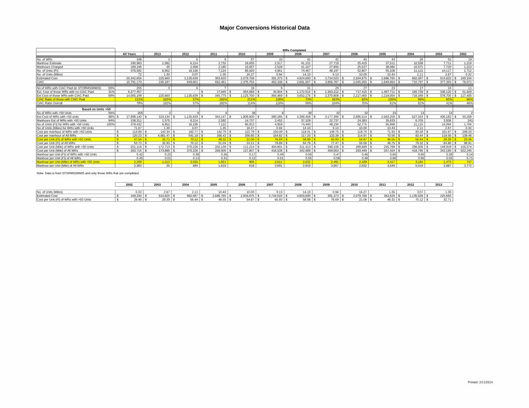
Major Conversions Historical Data
All Years 2013 2012 2011 2010 2009 2008 2007 2006 2005 2004 2003 2002
No. of WRs 348 3 6 9 57 10 42 42 40 43 26 51 19 Manhour Estimate 180,983 1,582 6,214 2,732 16,655 2,517 41,151 27,719 25,415 37,511 10,558 7,711 1,218 Manhours Charged 169,196 45 2,098 2,185 10,057 2,528 41,167 27,994 25,527 38,080 10,571 7,720 1,223 No. of Units (Ft) 378,582 6,852 16,196 7,124 85,920 4,961 74,467 48,197 52,807 55,108 11,121 14,117 1,712 No. of Units (Miles) 72 1.30 3.07 1.35 16.27 0.94 14.10 9.13 10.00 10.44 2.11 2.67 0.32 Estimated Cost 20,342,656 225,660 1,135,639 363,620 2,079,768 391,373 4,824,690$ 3,734,020$ 2,934,875$ 2,686,765$ 882,087$ 914,825$ 169,334$ CIAC 15,791,170 230,187 649,801 662,461 2,376,753 462,338 2,681,567$ 3,866,787$ 2,045,350$ 1,649,664$ 710,797$ 377,393$ 78,071$
No of WRs with CIAC Paid (in STORMS/WMIS) 59% 205 3 6 7 18 9 31 29 27 23 17 24 11 Est. Cost of those WRs with no CIAC Paid 31% 6,277,457 - - 17,845$ 954,068$ 30,904$ 1,172,514$ 1,363,212$ 717,415$ 1,467,711$ 165,739$ 336,120$ 51,929$ Est Cost of those WRs with CIAC Paid 69% 14,065,199 225,660 1,135,639 345,775$ 1,125,700$ 360,469$ 3,652,176$ 2,370,808$ 2,217,460$ 1,219,054$ 716,348$ 578,705$ 117,405$ CIAC Ratio of those with CIAC Paid 112% 102% 57% 192% 211% 128% 73% 163% 92% 135% 99% 65% 66%CIAC Ratio Overall 78% 102% 57% 182% 114% 118% 56% 104% 70% 61% 81% 41% 46%
Based on Units >50No of WRs with >50 Units 59% 205 2 6 6 36 9 30 32 32 23 13 14 2Est Cost of WRs with >50 units 88% 17,998,140$ 224,134$ 1,135,639$ 344,147$ 1,809,600$ 380,285$ 4,390,458$ 3,177,390$ 2,895,514$ 2,563,259$ 627,324$ 400,182$ 50,208$ Manhours Est of WRs with >50 Units 94% 158,311 1,575 6,214 2,592 14,737 2,452 37,109 22,737 24,383 35,633 6,703 3,936 241No of Units (Ft) for WRs with >50 Units 100% 378,432 6,852 16,196 7,122 85,913 4,959 74,440 48,194 52,775 55,068 11,115 14,094 1,704 No of Units (Miles) for WRs with >50 Units 71.67 1.30 3.07 1.35 16.27 0.94 14.10 9.13 10.00 10.43 2.11 2.67 0.32 Cost per manhour of WRs with >50 Units 113.69$ 142.34$ 182.77$ 132.79$ 122.79$ 155.09$ 118.31$ 139.75$ 118.75$ 71.93$ 93.59$ 101.67$ 208.33$ Cost per manhour of All WRs 120.23$ 4,981.47$ 541.19$ 166.42$ 206.80$ 154.82$ 117.20$ 133.39$ 114.97$ 70.56$ 83.44$ 118.50$ 138.46$ Cost per Unit (Ft) of WRs with >50 Units 47.56$ 32.71$ 70.12$ 48.32$ 21.06$ 76.69$ 58.98$ 65.93$ 54.87$ 46.55$ 56.44$ 28.39$ 29.46$ Cost per Unit (Ft) of All WRs 53.73$ 32.93$ 70.12$ 51.04$ 24.21$ 78.89$ 64.79$ 77.47$ 55.58$ 48.75$ 79.32$ 64.80$ 98.91$ Cost per Unit (Mile) of WRs with >50 Units 251,116$ 172,713$ 370,226$ 255,139$ 111,214$ 404,901$ 311,413$ 348,106$ 289,689$ 245,769$ 298,000$ 149,919$ 155,574$ Cost per Unit (Mile) of All WRs 283,715$ 173,889$ 370,226$ 269,500$ 127,807$ 416,539$ 342,089$ 409,063$ 293,449$ 257,424$ 418,795$ 342,160$ 522,245$ Manhour per Unit (Ft) of WRs with >50 Units 0.42 0.23 0.38 0.36 0.17 0.49 0.50 0.47 0.46 0.65 0.60 0.28 0.14Manhour per Unit (Ft) of All WRs 0.45 0.01 0.13 0.31 0.12 0.51 0.55 0.58 0.48 0.69 0.95 0.55 0.71Manhour per Unit (Mile) of WRs with >50 Units 2,209 1,213 2,026 1,921 906 2,611 2,632 2,491 2,439 3,417 3,184 1,475 747 Manhour per Unit (Mile) of All WRs 2,360 35 684 1,619 618 2,691 2,919 3,067 2,552 3,649 5,019 2,887 3,772
Note: Data is from STORMS/WMIS and only those WRs that are completed.
2002 2003 2004 2005 2006 2007 2008 2009 2010 2011 2012 2013
No. of Units (Miles) 0.32 2.67 2.11 10.43 10.00 9.13 14.10 0.94 16.27 1.35 3.07 1.30 Estimated Cost 169,334$ 914,825$ 882,087$ 2,686,765$ 2,934,875$ 3,734,020$ 4,824,690$ 391,373$ 2,079,768$ 363,620$ 1,135,639$ 225,660$ Cost per Unit (Ft) of WRs with >50 Units 29.46$ 28.39$ 56.44$ 46.55$ 54.87$ 65.93$ 58.98$ 76.69$ 21.06$ 48.32$ 70.12$ 32.71$
WRs Completed
Printed: 2/11/2014

ATTACHMENT M
MNT-TRMX-00053 Rev. 4 (08/10) Page 1 of 14
Document title
Transmission Line Material Condition Assessment Procedure; Ground Patrols Document number
MNT-TRMX-00053 Applies to: Transmission Operations and Planning Department – Carolinas and Florida Keywords: maintenance; transmission – maintenance line 1.0 Purpose
The material condition of the transmission line structures must be periodically assessed to ensure the assets are in optimum condition. The primary goal of the line assessment is to inspect transmission line structures and associated hardware on a routine basis with the purpose of finding and documenting any required material repairs or replacements. A secondary goal is to periodically inspect the general condition of the right-of-way including emergency type danger trees, ditches, access locations, and encroachments.
2.0 Determining Risk
The State Code represents a components present condition and ranges from a State 1 to State 5. The ground patrol requires the state of all the line components, including switches, poles, crossarms, conductors, etc., to be collected by means of computer software and uploaded into Cascade. This information is then integrated with the known criticality of the line. This determines the risk of the line to the Department. Unacceptable risks have high probabilities of degrading service to customers, negatively impacting reliability, or incurring increased O&M or capital costs to the company.
3.0 Terms and Definitions
3.1 Ground Patrol: The ground patrol is a detailed assessment of a line’s structures, crossarms, insulators, guys, anchors, static wires, and conductors. The ground patrol also includes an assessment of the overall condition of the right-of-way, including access, ditches, encroachments, and the recording of vegetation issues whose clearance to conductor warrant review by the Area Transmission Forester including dead, diseased, dying, leaning or uprooted trees.
3.2 Climbing Inspections: A key component of the ground patrol is evaluating the
condition of insulators & wood crossarms. These components cannot always be properly evaluated from the ground, even with binoculars. Therefore, when the condition of components up the structure appears suspect, poles & towers should be climbed or assessed with a bucket. This may expose line deficiencies that may be more widespread, such as penciled porcelain insulators on multiple structures.
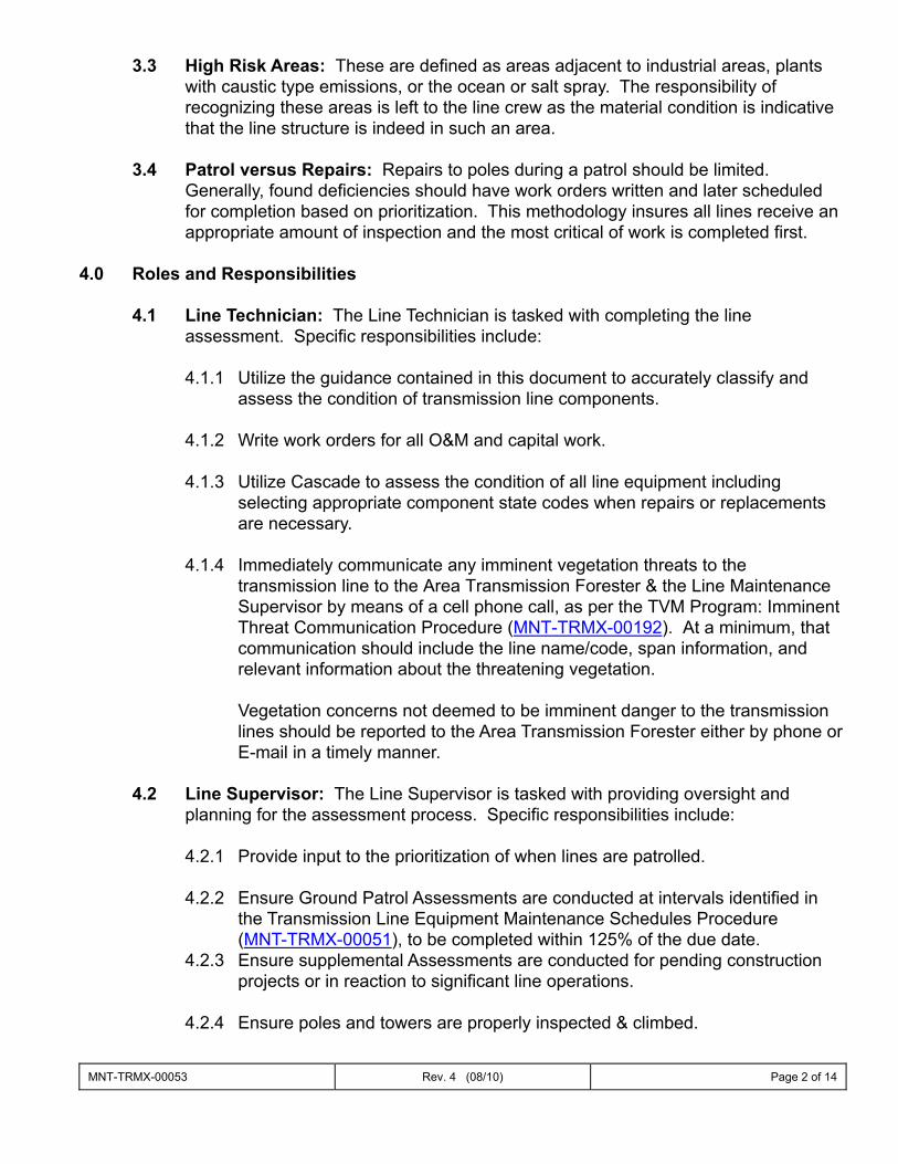
MNT-TRMX-00053 Rev. 4 (08/10) Page 2 of 14
3.3 High Risk Areas: These are defined as areas adjacent to industrial areas, plants with caustic type emissions, or the ocean or salt spray. The responsibility of recognizing these areas is left to the line crew as the material condition is indicative that the line structure is indeed in such an area.
3.4 Patrol versus Repairs: Repairs to poles during a patrol should be limited.
Generally, found deficiencies should have work orders written and later scheduled for completion based on prioritization. This methodology insures all lines receive an appropriate amount of inspection and the most critical of work is completed first.
4.0 Roles and Responsibilities
4.1 Line Technician: The Line Technician is tasked with completing the line assessment. Specific responsibilities include:
4.1.1 Utilize the guidance contained in this document to accurately classify and
assess the condition of transmission line components. 4.1.2 Write work orders for all O&M and capital work.
4.1.3 Utilize Cascade to assess the condition of all line equipment including
selecting appropriate component state codes when repairs or replacements are necessary.
4.1.4 Immediately communicate any imminent vegetation threats to the transmission line to the Area Transmission Forester & the Line Maintenance Supervisor by means of a cell phone call, as per the TVM Program: Imminent Threat Communication Procedure (MNT-TRMX-00192). At a minimum, that communication should include the line name/code, span information, and relevant information about the threatening vegetation.
Vegetation concerns not deemed to be imminent danger to the transmission
lines should be reported to the Area Transmission Forester either by phone or E-mail in a timely manner.
4.2 Line Supervisor: The Line Supervisor is tasked with providing oversight and
planning for the assessment process. Specific responsibilities include:
4.2.1 Provide input to the prioritization of when lines are patrolled. 4.2.2 Ensure Ground Patrol Assessments are conducted at intervals identified in
the Transmission Line Equipment Maintenance Schedules Procedure (MNT-TRMX-00051), to be completed within 125% of the due date.
4.2.3 Ensure supplemental Assessments are conducted for pending construction projects or in reaction to significant line operations.
4.2.4 Ensure poles and towers are properly inspected & climbed.
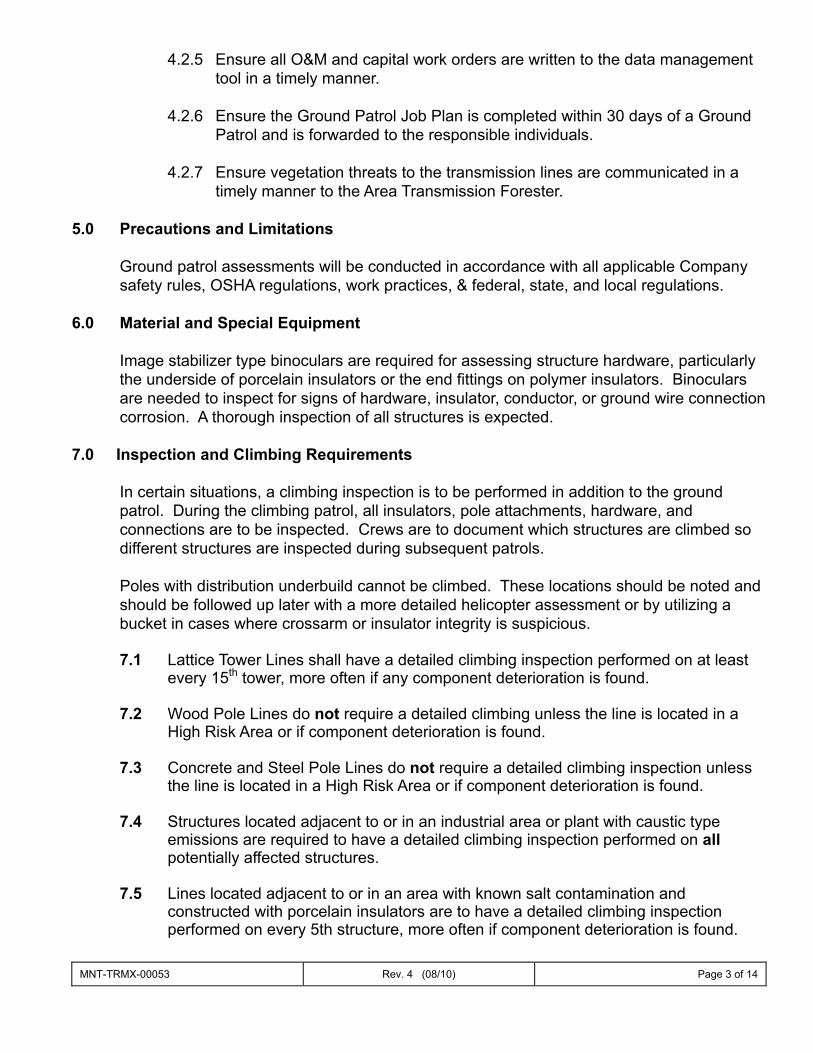
MNT-TRMX-00053 Rev. 4 (08/10) Page 3 of 14
4.2.5 Ensure all O&M and capital work orders are written to the data management tool in a timely manner.
4.2.6 Ensure the Ground Patrol Job Plan is completed within 30 days of a Ground
Patrol and is forwarded to the responsible individuals.
4.2.7 Ensure vegetation threats to the transmission lines are communicated in a timely manner to the Area Transmission Forester.
5.0 Precautions and Limitations
Ground patrol assessments will be conducted in accordance with all applicable Company safety rules, OSHA regulations, work practices, & federal, state, and local regulations.
6.0 Material and Special Equipment
Image stabilizer type binoculars are required for assessing structure hardware, particularly the underside of porcelain insulators or the end fittings on polymer insulators. Binoculars are needed to inspect for signs of hardware, insulator, conductor, or ground wire connection corrosion. A thorough inspection of all structures is expected.
7.0 Inspection and Climbing Requirements In certain situations, a climbing inspection is to be performed in addition to the ground patrol. During the climbing patrol, all insulators, pole attachments, hardware, and connections are to be inspected. Crews are to document which structures are climbed so different structures are inspected during subsequent patrols.
Poles with distribution underbuild cannot be climbed. These locations should be noted and should be followed up later with a more detailed helicopter assessment or by utilizing a bucket in cases where crossarm or insulator integrity is suspicious. 7.1 Lattice Tower Lines shall have a detailed climbing inspection performed on at least
every 15th tower, more often if any component deterioration is found. 7.2 Wood Pole Lines do not require a detailed climbing unless the line is located in a
High Risk Area or if component deterioration is found.
7.3 Concrete and Steel Pole Lines do not require a detailed climbing inspection unless the line is located in a High Risk Area or if component deterioration is found.
7.4 Structures located adjacent to or in an industrial area or plant with caustic type emissions are required to have a detailed climbing inspection performed on all potentially affected structures.
7.5 Lines located adjacent to or in an area with known salt contamination and
constructed with porcelain insulators are to have a detailed climbing inspection performed on every 5th structure, more often if component deterioration is found.
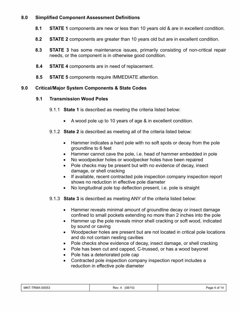
MNT-TRMX-00053 Rev. 4 (08/10) Page 4 of 14
8.0 Simplified Component Assessment Definitions
8.1 STATE 1 components are new or less than 10 years old & are in excellent condition.
8.2 STATE 2 components are greater than 10 years old but are in excellent condition. 8.3 STATE 3 has some maintenance issues, primarily consisting of non-critical repair
needs, or the component is in otherwise good condition.
8.4 STATE 4 components are in need of replacement.
8.5 STATE 5 components require IMMEDIATE attention.
9.0 Critical/Major System Components & State Codes
9.1 Transmission Wood Poles
9.1.1 State 1 is described as meeting the criteria listed below:
• A wood pole up to 10 years of age & in excellent condition. 9.1.2 State 2 is described as meeting all of the criteria listed below:
• Hammer indicates a hard pole with no soft spots or decay from the pole
groundline to 6 feet • Hammer cannot cave the pole, i.e. head of hammer embedded in pole • No woodpecker holes or woodpecker holes have been repaired • Pole checks may be present but with no evidence of decay, insect
damage, or shell cracking • If available, recent contracted pole inspection company inspection report
shows no reduction in effective pole diameter • No longitudinal pole top deflection present, i.e. pole is straight
9.1.3 State 3 is described as meeting ANY of the criteria listed below:
• Hammer reveals minimal amount of groundline decay or insect damage
confined to small pockets extending no more than 2 inches into the pole • Hammer up the pole reveals minor shell cracking or soft wood, indicated
by sound or caving • Woodpecker holes are present but are not located in critical pole locations
and do not contain nesting cavities • Pole checks show evidence of decay, insect damage, or shell cracking • Pole has been cut and capped, C-trussed, or has a wood bayonet • Pole has a deteriorated pole cap • Contracted pole inspection company inspection report includes a
reduction in effective pole diameter
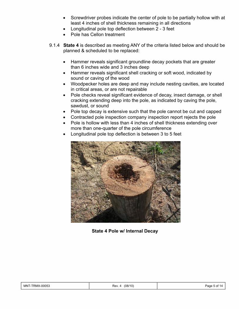
MNT-TRMX-00053 Rev. 4 (08/10) Page 5 of 14
• Screwdriver probes indicate the center of pole to be partially hollow with at least 4 inches of shell thickness remaining in all directions
• Longitudinal pole top deflection between 2 - 3 feet • Pole has Cellon treatment
9.1.4 State 4 is described as meeting ANY of the criteria listed below and should be
planned & scheduled to be replaced:
• Hammer reveals significant groundline decay pockets that are greater than 6 inches wide and 3 inches deep
• Hammer reveals significant shell cracking or soft wood, indicated by sound or caving of the wood
• Woodpecker holes are deep and may include nesting cavities, are located in critical areas, or are not repairable
• Pole checks reveal significant evidence of decay, insect damage, or shell cracking extending deep into the pole, as indicated by caving the pole, sawdust, or sound
• Pole top decay is extensive such that the pole cannot be cut and capped • Contracted pole inspection company inspection report rejects the pole • Pole is hollow with less than 4 inches of shell thickness extending over
more than one-quarter of the pole circumference • Longitudinal pole top deflection is between 3 to 5 feet
State 4 Pole w/ Internal Decay
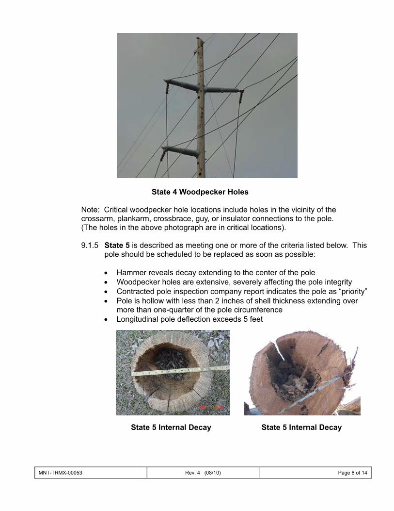
MNT-TRMX-00053 Rev. 4 (08/10) Page 6 of 14
State 4 Woodpecker Holes
Note: Critical woodpecker hole locations include holes in the vicinity of the crossarm, plankarm, crossbrace, guy, or insulator connections to the pole. (The holes in the above photograph are in critical locations).
9.1.5 State 5 is described as meeting one or more of the criteria listed below. This
pole should be scheduled to be replaced as soon as possible:
• Hammer reveals decay extending to the center of the pole • Woodpecker holes are extensive, severely affecting the pole integrity • Contracted pole inspection company report indicates the pole as “priority” • Pole is hollow with less than 2 inches of shell thickness extending over
more than one-quarter of the pole circumference • Longitudinal pole deflection exceeds 5 feet
State 5 Internal Decay State 5 Internal Decay
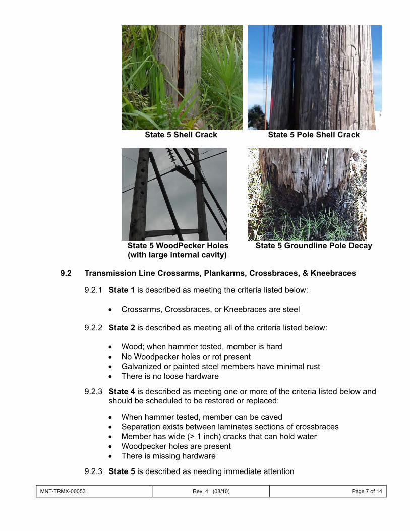
MNT-TRMX-00053 Rev. 4 (08/10) Page 7 of 14
State 5 Shell Crack State 5 Pole Shell Crack
State 5 WoodPecker Holes State 5 Groundline Pole Decay (with large internal cavity)
9.2 Transmission Line Crossarms, Plankarms, Crossbraces, & Kneebraces
9.2.1 State 1 is described as meeting the criteria listed below:
• Crossarms, Crossbraces, or Kneebraces are steel
9.2.2 State 2 is described as meeting all of the criteria listed below:
• Wood; when hammer tested, member is hard • No Woodpecker holes or rot present • Galvanized or painted steel members have minimal rust • There is no loose hardware
9.2.3 State 4 is described as meeting one or more of the criteria listed below and
should be scheduled to be restored or replaced:
• When hammer tested, member can be caved • Separation exists between laminates sections of crossbraces • Member has wide (> 1 inch) cracks that can hold water • Woodpecker holes are present • There is missing hardware
9.2.3 State 5 is described as needing immediate attention
MNT-TRMX-00053 Rev. 4 (08/10) Page 8 of 14
9.3 Transmission Line Lattice Towers, Steel & Concrete Poles
9.3.1 State 1 is described as meeting all of the criteria listed below:
• Poles or Towers are new, less than 10 years old • No visible signs of deterioration
9.3.2 State 2 is described as meeting all of the criteria listed below: • Galvanized or painted steel pole or towers have minimal surface rust • No pack-out on tower bracing at member connections to tower legs • Groundline treatment on steel pole or tower is totally intact & has not
deteriorated • Grout on top of concrete pole is intact • Concrete surface may have hairline cracks, but less than 1/8 inch wide
9.3.3 State 3 is described as meeting one or more of the criteria listed below: • Galvanized or painted steel pole or towers have rust and needs painting • Weathering steel poles or tower members exhibit minimal pitting • Aluminum towers exhibit minimal surface deterioration. • Light pack-out on tower bracing at member connections to tower legs • Groundline treatment on steel pole or tower is cracked, or peeled, but
rusting has not yet occurred • Grout on top of concrete pole is cracked • Concrete surface may have hairline cracks, but less than 1/8 inch wide
9.3.4 State 4 is described as meeting one or more of the criteria listed below:
• Galvanized or painted steel pole or towers have deep rust, needs cleaning, priming, & painting
• Weathering steel poles or towers exhibit heavy pack-out including deformed or missing members or bolts
• Aluminum towers exhibit deformed or missing members or bolts • Concrete poles has rust stains originating from inside the crack from the
reinforcing steel or cracks more that ¼ inch wide
9.3.5 State 5 is described as needing immediate attention
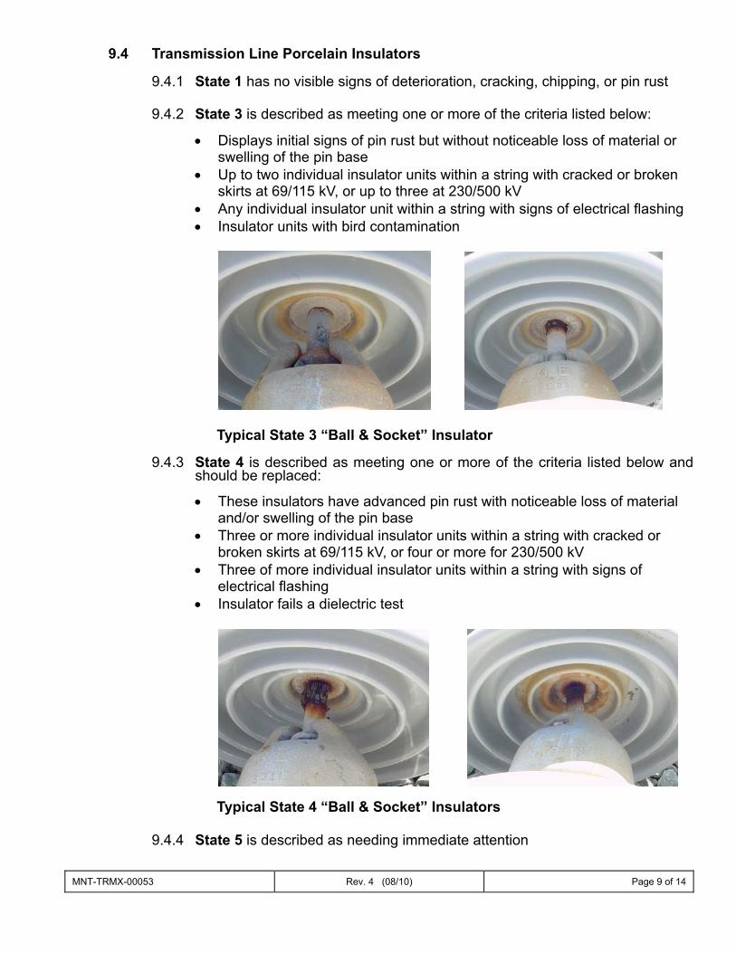
MNT-TRMX-00053 Rev. 4 (08/10) Page 9 of 14
9.4 Transmission Line Porcelain Insulators
9.4.1 State 1 has no visible signs of deterioration, cracking, chipping, or pin rust
9.4.2 State 3 is described as meeting one or more of the criteria listed below:
• Displays initial signs of pin rust but without noticeable loss of material or swelling of the pin base
• Up to two individual insulator units within a string with cracked or broken skirts at 69/115 kV, or up to three at 230/500 kV
• Any individual insulator unit within a string with signs of electrical flashing • Insulator units with bird contamination
Typical State 3 “Ball & Socket” Insulator
9.4.3 State 4 is described as meeting one or more of the criteria listed below and
should be replaced:
• These insulators have advanced pin rust with noticeable loss of material and/or swelling of the pin base
• Three or more individual insulator units within a string with cracked or broken skirts at 69/115 kV, or four or more for 230/500 kV
• Three of more individual insulator units within a string with signs of electrical flashing
• Insulator fails a dielectric test
Typical State 4 “Ball & Socket” Insulators
9.4.4 State 5 is described as needing immediate attention

MNT-TRMX-00053 Rev. 4 (08/10) Page 10 of 14
9.5 Transmission Line Polymer Insulators
9.5.1 State 1 has no visible signs of deterioration
9.5.2 State 3 has moderate amounts of chalking
9.5.3 State 4 is described as meeting one or more of the criteria listed below and should be replaced:
• Has an exposed fiberglass rod • Has open splits or gaps in the rubber housing • Displays signs of electrical tracking or leaking interface compound • Has missing corona rings (230 kV)
Exposed Fiberglass Rod (Ohio Brass)
Split Housing (Ohio Brass)
9.5.4 State 5 is described as needing immediate attention
MNT-TRMX-00053 Rev. 4 (08/10) Page 11 of 14
9.6 Transmission Line Conductors
9.6.1 State 2 conductor has no visible wear
9.6.2 State 3 is described as meeting one or more of the criteria listed below and should be repaired:
• Minor core rusting or corrosion • Minor “Birdcage” of any conductor • Conductor aluminum strands are unraveled • Ohm-stick” conductor splice resistance readings indicating a
recommended recheck in one year
9.6.3 State 4 is described as needing immediate attention and meets one or more of the criteria listed below and should be repaired or replaced:
• Conductor steel core has severe corrosion. • Conductor shot through the steel strands. • “Ohm-stick” conductor splice resistance readings indicating a
recommendation to immediately replace
9.6.4 State 5 is described as needing immediate attention
9.7 Transmission Line Overhead Ground Wires (Statics, OHGW, OHG, OPGW)
9.7.1 State 2 static has no visible wear
9.7.2 State 3 is described as meeting one or more of the criteria listed below:
• Static has minor rusting, corrosion, or visible pitting • Mechanical static splices present • Statics including 5/16”, 3#6, & 7#10 • “Ohm-stick” conductor splice resistance readings indicating a
recommended recheck in one year
9.7.3 State 4 is described as meeting one or more of the criteria listed below and should be repaired or replaced:
• Any broken strands • “Ohm-stick” conductor splice resistance readings indicating a
recommendation to immediately replace. • Static is severely rusted and or has become brittle. This condition can
also be supported with lab testing of static samples.
9.7.4 State 5 is described as needing immediate attention
9.8 Transmission Line Anchors and Guy Wires
9.8.1 State 2 anchors & guys have no visible wear
• Guy Grips & anchor heads are all above groundline • Guys are tight.
MNT-TRMX-00053 Rev. 4 (08/10) Page 12 of 14
9.8.2 State 3 is described as meeting one or more of the criteria listed below:
• Guys have been damaged • Guy Grips & anchor heads are at or below groundline • Grade modifications have exposed the top portion of the anchor • Guys are loose and can be swayed
9.8.3 State 5 is described as needing immediate attention
9.9 Transmission Line Switches
9.9.1 State 1 is described as meeting all of the criteria listed below:
• The switch is new or less than 10 years old & is in excellent condition. • All preventative maintenance is completed within 125% of the established
due date • No know material defects • Infrared readings are normal
9.9.2 State 2 is described as meeting all of the criteria listed below:
• The switch is greater than 10 years old & is in excellent condition • All preventative maintenance is completed within 125% of the established
due date • No know material defects • Infrared readings are normal
9.9.3 State 3 is described as meeting one or more of the criteria listed below:
• Preventative maintenance activities are overdue by more than 125% of the established completion date
• Switch has a history of mechanical issues that have required attention on several occasions
• Switch is mounted on a wood pole structure • Infrared readings slightly above normal
9.9.4 State 4 is described as meeting one or more of the criteria listed below:
• Preventative maintenance activities are overdue by more than 150% of the established completion date.
• Switch has mechanical issues that require attention whenever it is operated
• Infrared readings are high and require adjustment of blade/jaw interface or replacement
MNT-TRMX-00053 Rev. 4 (08/10) Page 13 of 14
9.9.5 State 5 is described as needing immediate attention, or:
• Infrared readings indicate immediate action is required • The switch is tagged out of service with the ECC due to mechanical or
operational problems • Interrupter has lost dielectric strength, i.e. no vacuum or gas is present.
9.10 Transmission Minor Components
9.10.1 Aerial Markers; Inspect for faded, partially detached, or missing
markers. 9.10.2 Arrestors; Inspect for loose hardware, detached jumpers, cracks,
signs of being burned, or with high infrared readings. 9.10.3 Bird Contamination; Inspect for bird droppings on crossarms, the
ground, and stains on porcelain insulator strings. Significant activity may warrant the installation of protective bird guards.
9.10.4 Conductor Splices; Inspect for rusted strands or a discharge of the
conductive grease at the splice ends. The color will normally be black. Elevated infrared readings will indicate if the splice is in a critical state. The “Ohmstick” is an effective means of evaluating a splices’ integrity.
9.10.5 Connections; Inspect for bent, cracked, or missing hardware, and
loose or missing bolts. 9.10.6 Dampers; Inspect for bent, cracked, or missing nuts. Look for signs of
being broken loose and sliding away from the insulator. 9.10.7 Encroachments; Inspect for buildings, deer stands, ditches, fences,
and elevation changes including ditches affecting access and mounds. 9.10.8 Grounding; Inspect for broken or deteriorated pole grounds and for
unattached flying taps or bonding straps to the overhead ground wire. 9.10.9 Guy Strain Insulators; Inspect coatings for cracking and chipping as
they protect the fiberglass insulator rod from ultraviolet radiation. Inspect end fittings for deterioration. Insulators with significantly frayed glass or splintering should be replaced.
9.10.10 Line Traps; Inspect for bent, cracked, or missing hardware. 9.10.11 Pole Bands; Inspect for broken thru bolts and pulled out lag screws,
particularly on conductor deadends.
MNT-TRMX-00053 Rev. 4 (08/10) Page 14 of 14
9.10.12 ROW Condition; Inspect for burn or dirt piles, trees that may affect the
reliability of the line, vines, and any change in grade due to earthmoving activities.
9.10.13 U-bolts used on steel crossarms; Inspect for loose hardware.
Particular attention should be given to rusting nuts and washers on 5/8” diameter weathering U-bolts.
9.10.14 Warning Signs; Inspect for faded, detached or missing signs. Insure
signs used for helicopter patrols are present at all crossings.
10.0 References
10.1 Ground Patrol Assessments shall be followed in accordance with the Transmission Maintenance Program Policy (MNT-TRMX-00000).
10.2 Ground Patrol Assessments will be conducted at intervals identified in the
Transmission Line Equipment Maintenance Schedules Procedure (MNT-TRMX-00051).

ATTACHMENT O
Matthew R. Bernier Sr. Counsel Duke Energy Florida, Inc.
February 28, 2014 VIA ELECTRONIC MAIL Mr. Tom Ballinger, Director Division of Engineering Florida Public Service Commission 2540 Shumard Oak Boulevard Tallahassee, Florida 32399-0850
Re: 2013 Annual Wood Pole Inspection Report; Undocketed Dear Ms. Stauffer:
Pursuant to Order Nos. PSC-06-0144-PAA-EI and PSC-07-0918-PAA-PU, enclosed is Duke Energy Florida, Inc.’s (“DEF”) Annual Wood Pole Inspection Report for CY 2013. This information is also contained in DEF’s 2013 Annual Service Reliability Report dated February 28, 2014.
Thank you for your assistance in this matter. Please feel free to call me at (850) 521-1428 should you have any questions concerning this filing.
Respectfully, s/Matthew R. Bernier Matthew R. Bernier Sr. Counsel [email protected]
MRB/mw Enclosures
DUKE ENERGY FLORIDA’S 2013 ANNUAL WOOD POLE INSPECTION REPORT
I. In Order No. PSC-06-0144-PAA-EI, the Commission stated that on an annual basis,
investor-owned electric utilities shall file wood pole inspection reports containing the following information:
A review of the methods the company used to determine NESC compliance for strength and structural integrity of the wood poles included in the previous year’s annual inspections, taking into account pole loadings, where required;
An explanation of the inspected poles selection criteria, including, among other things, geographic location and the rationale for including each such selection criterion; and
Summary data and results of the company’s previous year’s wood pole inspections, addressing the strength, structural integrity, and loading requirements of the NESC.
In compliance with Order No. PSC-06-0144-PAA-EI, Duke Energy Florida (“DEF”) submits the following information for calendar year 2013:
METHODS USED
Please see Attachment A – Column J. For a more detailed explanation of the methods used, please refer to DEF’s1 Wood Pole Inspection Plan filed on April 2, 2012. SELECTION CRITERIA See comments on Attachment A. SUMMARY DATA AND RESULTS Please see Attachment A.
1 DEF’s 2012 Wood Pole Inspection Plan was filed in the name of DEF’s predecessor, Progress Energy Florida, Inc. (“PEF”). All references herein to Progress Energy Florida, Inc. or PEF should be understood to refer to DEF.
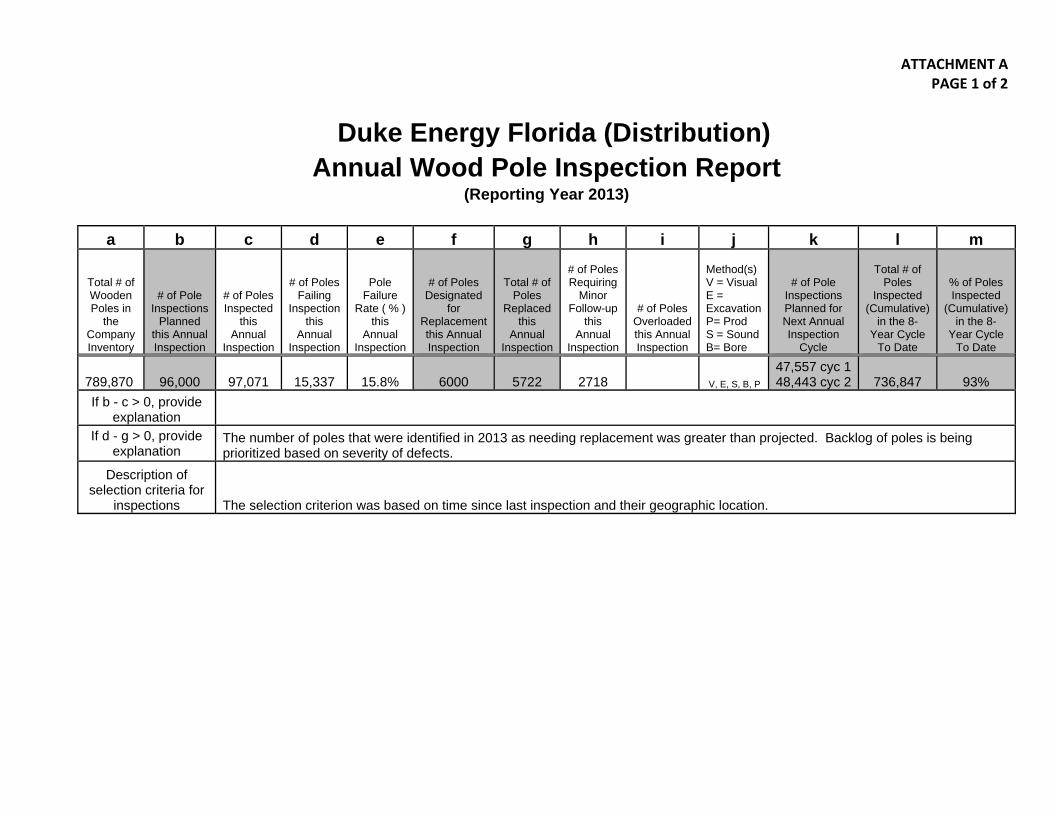
ATTACHMENT A PAGE 1 of 2
Duke Energy Florida (Distribution) Annual Wood Pole Inspection Report
(Reporting Year 2013) a b c d e f g h i j k l m
Total # of Wooden Poles in
the Company Inventory
# of Pole Inspections
Planned this Annual Inspection
# of Poles Inspected
this Annual
Inspection
# of Poles Failing
Inspection this
Annual Inspection
Pole Failure
Rate ( % ) this
Annual Inspection
# of Poles Designated
for Replacement this Annual Inspection
Total # of Poles
Replaced this
Annual Inspection
# of Poles Requiring
Minor Follow-up
this Annual
Inspection
# of Poles Overloaded this Annual Inspection
Method(s) V = Visual E = Excavation P= Prod S = Sound B= Bore
# of Pole Inspections Planned for Next Annual Inspection
Cycle
Total # of Poles
Inspected (Cumulative)
in the 8-Year Cycle
To Date
% of Poles Inspected
(Cumulative) in the 8-
Year Cycle To Date
789,870 96,000 97,071 15,337 15.8% 6000 5722 2718 V, E, S, B, P
47,557 cyc 148,443 cyc 2 736,847 93%
If b - c > 0, provide explanation
If d - g > 0, provide explanation
The number of poles that were identified in 2013 as needing replacement was greater than projected. Backlog of poles is being prioritized based on severity of defects.
Description of selection criteria for
inspections The selection criterion was based on time since last inspection and their geographic location.
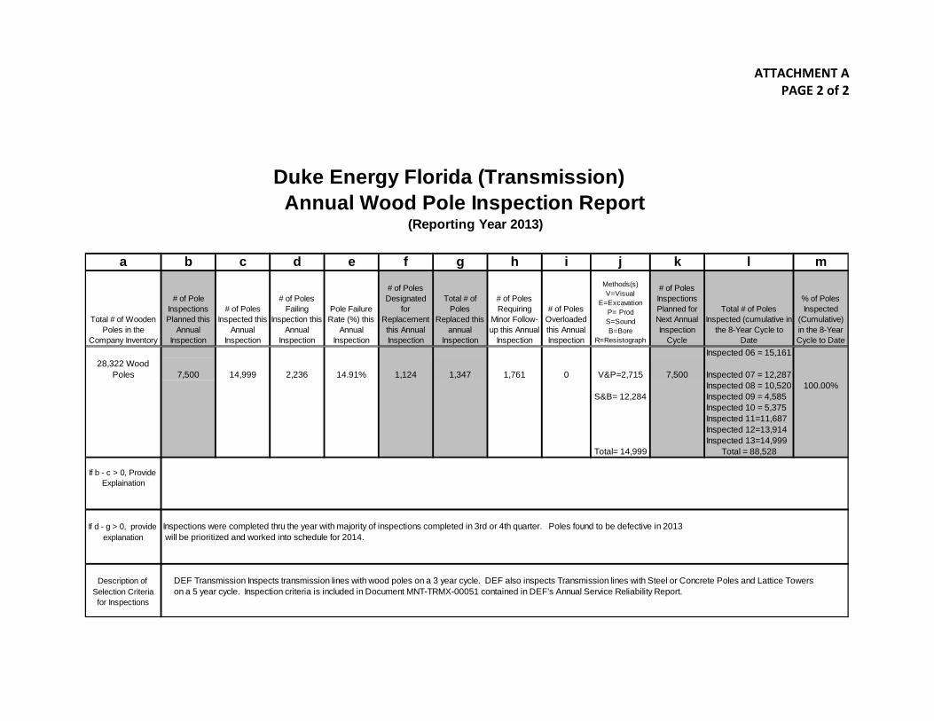
ATTACHMENT A
PAGE 2 of 2
Duke Energy Florida (Transmission) Annual Wood Pole Inspection Report
(Reporting Year 2013)
a b c d e f g h i j k l m
Total # of Wooden Poles in the
Company Inventory
# of Pole Inspections Planned this
Annual Inspection
# of Poles Inspected this
Annual Inspection
# of Poles Failing
Inspection this Annual
Inspection
Pole Failure Rate (%) this
Annual Inspection
# of Poles Designated
for Replacement this Annual Inspection
Total # of Poles
Replaced this annual
Inspection
# of Poles Requiring
Minor Follow-up this Annual
Inspection
# of Poles Overloaded this Annual Inspection
Methods(s) V=Visual
E=Excavation P= Prod S=Sound B=Bore
R=Resistograph
# of Poles Inspections Planned for Next Annual Inspection
Cycle
Total # of Poles Inspected (cumulative in
the 8-Year Cycle to Date
% of Poles Inspected
(Cumulative) in the 8-Year Cycle to Date
Inspected 06 = 15,16128,322 Wood
Poles 7,500 14,999 2,236 14.91% 1,124 1,347 1,761 0 V&P=2,715 7,500 Inspected 07 = 12,287Inspected 08 = 10,520 100.00%
S&B= 12,284 Inspected 09 = 4,585Inspected 10 = 5,375Inspected 11=11,687Inspected 12=13,914Inspected 13=14,999
Total= 14,999 Total = 88,528
If b - c > 0, Provide Explaination
If d - g > 0, provide Inspections were completed thru the year with majority of inspections completed in 3rd or 4th quarter. Poles found to be defective in 2013explanation will be prioritized and worked into schedule for 2014.
Description of DEF Transmission Inspects transmission lines with wood poles on a 3 year cycle. DEF also inspects Transmission lines with Steel or Concrete Poles and Lattice TowersSelection Criteria on a 5 year cycle. Inspection criteria is included in Document MNT-TRMX-00051 contained in DEF's Annual Service Reliability Report. for Inspections
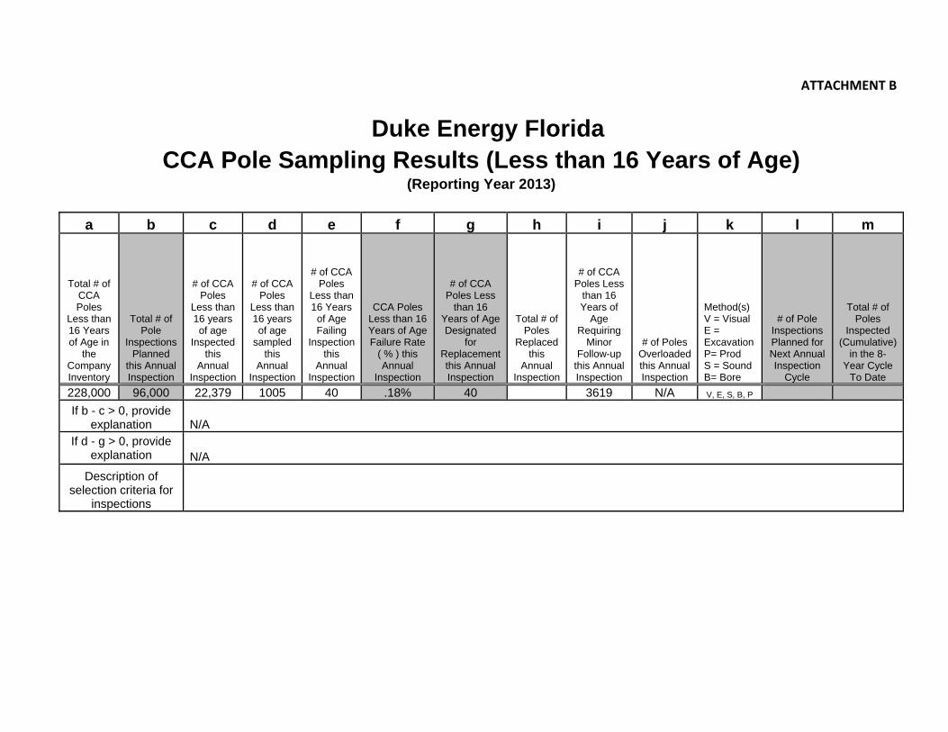
ATTACHMENT B
Duke Energy Florida CCA Pole Sampling Results (Less than 16 Years of Age)
(Reporting Year 2013) a b c d e f g h i j k l m
Total # of CCA Poles
Less than 16 Years of Age in
the Company Inventory
Total # of Pole
Inspections Planned
this Annual Inspection
# of CCA Poles
Less than 16 years of age
Inspected this
Annual Inspection
# of CCA Poles
Less than 16 years of age
sampled this
Annual Inspection
# of CCA Poles
Less than 16 Years
of Age Failing
Inspection this
Annual Inspection
CCA Poles Less than 16 Years of Age Failure Rate
( % ) this Annual
Inspection
# of CCA Poles Less
than 16 Years of Age Designated
for Replacement this Annual Inspection
Total # of Poles
Replaced this
Annual Inspection
# of CCA Poles Less
than 16 Years of
Age Requiring
Minor Follow-up
this Annual Inspection
# of Poles Overloaded this Annual Inspection
Method(s) V = Visual E = Excavation P= Prod S = Sound B= Bore
# of Pole Inspections Planned for Next Annual Inspection
Cycle
Total # of Poles
Inspected (Cumulative)
in the 8-Year Cycle
To Date 228,000 96,000 22,379 1005 40 .18% 40 3619 N/A V, E, S, B, P If b - c > 0, provide
explanation N/A If d - g > 0, provide
explanation N/A Description of
selection criteria for inspections

ATTACHMENT P – See Excel File

ATTACHMENT Q – See Excel File

ATTACHMENT R
Ongoing Storm Preparedness Plan
1
Purpose and Intent of the Plan: To implement Duke Energy Florida’s (“DEF”) Ongoing Storm Preparedness Plan (the “Plan”)1 that complies with FPSC Order No. PSC-06-0351-PAA-EI issued April 25, 2006 (the “Order”). The Plan addresses the specific ten-points that the Florida Public Service Commission (the “Commission”) identified in the Order. The Plan includes the following specific sub-plans:
• Vegetation Management Cycle for Distribution Circuits. • Audit of Joint Use Attachment Agreements. • Transmission Structure Inspection Program. • Hardening of Existing Transmission Structures. • Transmission and Distribution Geographic Information System. • Post-Storm Data Collection and Forensic Analysis. • Collection of Outage Data Differentiating Between the Reliability Performance of Overhead and
Underground Systems. • Increased Utility Coordination With Local Governments. • Collaborative Research on Effects of Hurricane Winds and Storm Surge. • Natural Disaster Preparedness and Recovery Program.
These ten sub-plans are outlined and described below. DEF has already implemented several of the sub-plans. All of these sub-plans will be evaluated on an ongoing basis to address, among other things, data and data trends, new information, external factors, and cost effectiveness. All cost figures provided in this Plan are DEF’s best estimates based on available information and data and are subject to revision and change as circumstances may dictate or as more definitive information becomes available.
1) Vegetation Management Cycle for Distribution Circuits DEF recommends a fully integrated vegetation management (“IVM”) program. The IVM program consists of at least the following subprograms: routine maintenance “trimming,” herbicide applications, vine removal, customer request work “tickets,” and right-of-way floor brush “mowing.” The IVM program incorporates a combination of both cycle based maintenance and reliability driven prioritization of work. Actual spending versus initial budget can vary during any particular year based on a number of factors which may include timing, changes in priorities within the program, and unforeseen events such as major storms and other factors. 1 The Ongoing Storm Preparedness Plan was provided to the Commission by DEF’s predecessor, Progress Energy Florida, Inc. (“PEF”) per Order No. PSC-06-0351-PAA-EI. DEF confirms there are no substantive changes to the Plan.
Ongoing Storm Preparedness Plan
2
Based on these considerations, DEF has revised its vegetation management contracts to add items such as:
• Cutting brush within an eight foot radius of all device poles;
• To the extent practical and reasonably feasible, felling “dead danger trees” within 25 feet of the closest conductor that have a high likelihood of falling on the conductors; and
• Cutting of underbrush instead of topping it.
These items have been added to help address some of the emerging issues in both the preventable and non-preventable tree-caused outage categories.
In general, the main objectives are to optimize the IVM program cost against reliability and storm performance objectives. Some of the main program objectives are: • Customer and employee safety; • Tree caused outage minimization, with the objective to reduce the number of tree caused
outages, particularly in the “preventable” category; • Effective cost management; and • Customer satisfaction, with the goal to provide the customer top quartile service.
As part of the IVM program, DEF has implemented a comprehensive feeder prioritization model to help ensure that tree caused outages are minimized by focusing on the feeders that rate high in the model. Prioritization ranking factors are based on past feeder performance and probable future performance. Some of the criteria used in feeder prioritization include the number of customers per mile, the number of tree caused outages in prior years, outages per mile, the percentage of outages on backbone feeders, the percentage of total tree outages categorized as preventable (i.e., outages caused by trees within DEF rights-of-way), and total tree customer minutes of interruption (“CMI”). In implementing this prioritized process, DEF follows the ANSI 300 standard for pruning and utilizes the “Pruning Trees Near Electric Utility Lines” by Dr. Alex L. Shigo. Generally, DEF attempts to maintain an average trimming cycle of three years. Although DEF works toward a benchmark goal of a three-year weighted average system maintenance cycle, it balances this goal against overall system reliability, customer impact, and cost effectiveness in determining its ultimate trim cycles. In some instances, DEF may defer maintenance on some feeders without significantly impacting reliability while accelerating maintenance on other feeders that are experiencing more significant issues than others. This approach has resulted in a significant improvement in system reliability, as measured by SAIDI, since 2001, including an improved SAIDI related to tree caused outages. A mandatory three-year trim cycle without regard to system reliability, customer impact, and cost-effectiveness would not benefit DEF’s customers when compared to a focused and targeted plan such as DEF’s IVM program. Additionally, in recent years, DEF has experienced availability challenges within the tree trimming labor force in Florida. A non-targeted, mandatory three-year trim cycle would adversely impact all electric utilities within the state by forcing them to compete for an already scarce resource.
Ongoing Storm Preparedness Plan
3
Such demand could be expected to inflate costs for all utilities. Further, a mandatory, non-targeted three-year cycle would not provide the flexibility that DEF can currently leverage to address tree conditions that can vary significantly depending a number of variables, most significantly weather conditions. DEF estimates that a mandatory three-year cycle would immediately increase costs by approximately $7M in the first year of its implementation and could increase DEF’s overall budget needs at a conservative rate of three percent (3%) per year. DEF does not endorse this approach. Rather, DEF can more effectively manage tree resources while providing the maximum benefit to our customers by utilizing DEF’s IVM program.
2) Audit of Joint Use Attachment Agreements. DEF currently has approximately 700,000 joint use attachments on distribution poles and approximately 5,000 joint use attachments on transmission poles. While the majority of these attachments are on wood poles, approximately 15% of the distribution joint use attachments are on concrete or metal structures and approximately 25% of the transmission joint use attachments are on concrete or metal poles. The information provided below outlines DEF’s plan to gather information on “non-wood” existing joint use poles over an average 8-year inspection cycle as outlined in Order No. PCS-06-0144-PAA-EI. DEF plans to inspect all DEF distribution poles (regardless of pole type) with joint use attachments on the 8 year audit cycle outlined in Order No. PCS-06-0144-PAA-EI. These audits will start at the sub-station where the feeder originates. For each group of poles in a tangent line, the pole that has the most visible loading, line angle, and longest or uneven span length will be selected to be modeled for wind loading analysis. Each pole modeled will be field inspected. The attachment heights of all electric and communication cables and equipment will be collected. The pole age, pole type, pole number, pole size / class, span lengths of cables and wires, and the size of all cables and wires on all sides of the pole will be collected.
The selected pole’s information will then be loaded into a software program. The pole information will be analyzed and modeled under the NESC Light District settings of 9psf, no ice, 30° F, at 60 MPH winds to determine current loading percentages. If that one pole fails, the next worst case pole in that group of tangent poles will be analyzed as well. Each pole analyzed will determine the existing pole loading of all electric and communication attachments on that pole. If the existing analysis determines that the pole is overloaded, a work order will be issued to replace the pole with a larger class pole. Should the original pole analyzed meet the NESC loading requirements, all similar poles in that tangent line of poles will be noted as structurally sound and entered into the database as “PASSED” structural analysis. The results of the analysis and all communication attachments will be entered into the FRAMME system. Reporting from the FRAMME system will indicate the date and results of the analysis. Poles rated at 100% or lower will be designated as “PASSED.” Poles that are analyzed and determined to be more than 100% loaded will be designated as “FAILED,” and scheduled to be changed out. Once the pole is changed out, FRAMME will be updated to reflect the date the new pole was installed with the new loading analysis indicated.

Ongoing Storm Preparedness Plan
4
DEF plans to inspect all transmission poles (regardless of pole type) with joint use attachments on the 8 year audit cycle outlined in Order No. PCS-06-0144-PAA-EI and DEF’s Pole Inspection Plan filed with the Commission on April 1, 2006. Audits will start at the sub-station where the transmission circuit originates. All pole information (pole size, class, type, age, pole number, cable, wire, equipment attachment heights, span lengths) including structural plan and profiles will be sent to an outside engineering firm to be modeled in PLS-CADD/LITE and PLS-POLE software for structural analysis. The firm will determine the worst case structures in a tangent line and request the structural drawings and attachment information on those selected poles. Typically, transmission poles with line angle and uneven span lengths are the poles considered for wind loading analysis. The selected pole information will be loaded into the PLS-CADD and PLS-POLE software. Depending on the pole location per the NESC wind charts, one of the following load cases is run. NESC Light District: 9psf, no ice, 30° F, 60mph; NESC Extreme: 3 sec gust for the specific county, no ice, 60° F (Ex: Orange County is 110 mph); or DEF Extreme at 36psf, 75° F, wind chart mph. If that one transmission pole fails, the next worst case pole in that group of tangent poles will be analyzed as well. Each transmission pole analyzed will determine the existing pole loading of all electric and communication attachments on that pole. If the existing analysis determines the transmission pole is overloaded, a work order will be issued to replace the pole with a stronger pole. Should the original pole analyzed meet the NESC loading requirements, all similar poles in that tangent line of poles will be noted as structurally sound and entered into the database as “PASSED” structural analysis.
The results of the analysis and all communication attachments will be entered into the FRAMME system. Reporting from the FRAMME system will indicate the date and results of the analysis. Transmission poles rated at 100% or lower will be designated as “PASSED.” Transmission poles that are analyzed and determined to be more than 100% loaded will be designated as “FAILED,” and scheduled to be changed out. Once the transmission pole is changed out, FRAMME will be updated to reflect the date the new pole was installed with the new loading analysis indicated. Pursuant to the requirements of FPSC Order No. PCS-06-0144-PAA-EI, DEF will file a wood pole inspection report with the Division of Economic Regulation by March 1st of each year. The report shall contain the following information:
1) A description of the methods used for structural analysis and pole inspection. 2) A description of the selection criteria that was used to determine which poles would be
inspected.
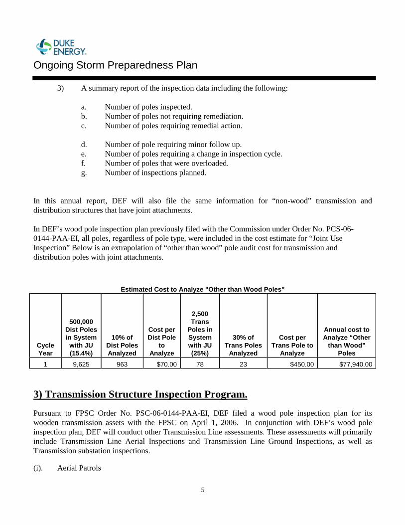
Ongoing Storm Preparedness Plan
5
3) A summary report of the inspection data including the following:
a. Number of poles inspected. b. Number of poles not requiring remediation. c. Number of poles requiring remedial action. d. Number of pole requiring minor follow up. e. Number of poles requiring a change in inspection cycle. f. Number of poles that were overloaded. g. Number of inspections planned.
In this annual report, DEF will also file the same information for “non-wood” transmission and distribution structures that have joint attachments. In DEF’s wood pole inspection plan previously filed with the Commission under Order No. PCS-06-0144-PAA-EI, all poles, regardless of pole type, were included in the cost estimate for “Joint Use Inspection” Below is an extrapolation of “other than wood” pole audit cost for transmission and distribution poles with joint attachments.
3) Transmission Structure Inspection Program. Pursuant to FPSC Order No. PSC-06-0144-PAA-EI, DEF filed a wood pole inspection plan for its wooden transmission assets with the FPSC on April 1, 2006. In conjunction with DEF’s wood pole inspection plan, DEF will conduct other Transmission Line assessments. These assessments will primarily include Transmission Line Aerial Inspections and Transmission Line Ground Inspections, as well as Transmission substation inspections. (i). Aerial Patrols
Estimated Cost to Analyze "Other than Wood Poles"
Cycle Year
500,000 Dist Poles in System
with JU (15.4%)
10% of Dist Poles Analyzed
Cost per Dist Pole
to Analyze
2,500 Trans
Poles in System with JU (25%)
30% of Trans Poles
Analyzed
Cost per Trans Pole to
Analyze
Annual cost to Analyze “Other
than Wood” Poles
1 9,625 963 $70.00 78 23 $450.00 $77,940.00
Ongoing Storm Preparedness Plan
6
Aerial patrols will utilize helicopter surveys of the transmission system on average three times per year to identify potential problems and needed corrective actions. Patrols will be conducted with qualified Line and Forestry personnel to look for and document conditions on the following items: Guys Braces Conductors Substation Equipment Aerial Markers Poles Crossarms Line Traps Arresters OHGW & OPGW Encroachments ROW Condition Insulators Splices/Dampers Line Sect. Switches Vegetation Issues The aerial patrols will inspect the condition of 69 - 500 kV voltage class transmission lines and associated hardware/equipment. These patrols will be used to aid the Transmission Line Maintenance Crew in scheduling and planning preventive/corrective maintenance work. (ii). Transmission Line Ground Inspections DEF will perform ground patrols to inspect transmission system line assets to allow for the planning, scheduling, and prioritization of corrective and preventative maintenance work. These patrols will assess the overall condition of the assets including insulators, connections, grounding, and signs, as well as an assessment of pole integrity. Each transmission line shall have a ground patrol conducted once every 5 years. The primary goal of a ground patrol is to inspect transmission line structures and associated hardware on a routine basis with the purpose of finding and documenting any required material repairs or replacements. (iii) Structural Integrity Evaluation The joint use inspector will note and record the type and location of non-native utility pole attachments to the pole or structure. This information will be used by the Joint Use Department to perform a loading analysis, where necessary, of the pole or structure. Specific information on this process is contained in the Joint Use section of this Plan. (iv). Transmission Substation Inspections DEF will perform monthly inspections of Transmission – Transmission Substations, Transmission – Distribution Substations and Generation Plant Substations. These inspections will consist of a visual analysis of Substation Assets and documentation of operation information. This visual inspection and operation information will be used to develop actions to correct any discrepancies and to schedule preventative maintenance. (v). Records and Reporting
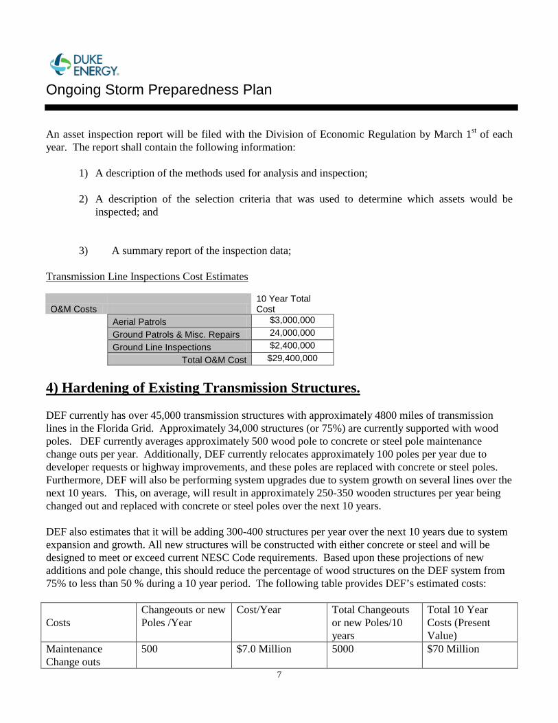
Ongoing Storm Preparedness Plan
7
An asset inspection report will be filed with the Division of Economic Regulation by March 1st of each year. The report shall contain the following information:
1) A description of the methods used for analysis and inspection; 2) A description of the selection criteria that was used to determine which assets would be
inspected; and 3) A summary report of the inspection data;
Transmission Line Inspections Cost Estimates
O&M Costs 10 Year Total Cost
Aerial Patrols $3,000,000 Ground Patrols & Misc. Repairs 24,000,000
Ground Line Inspections $2,400,000 Total O&M Cost $29,400,000
4) Hardening of Existing Transmission Structures. DEF currently has over 45,000 transmission structures with approximately 4800 miles of transmission lines in the Florida Grid. Approximately 34,000 structures (or 75%) are currently supported with wood poles. DEF currently averages approximately 500 wood pole to concrete or steel pole maintenance change outs per year. Additionally, DEF currently relocates approximately 100 poles per year due to developer requests or highway improvements, and these poles are replaced with concrete or steel poles. Furthermore, DEF will also be performing system upgrades due to system growth on several lines over the next 10 years. This, on average, will result in approximately 250-350 wooden structures per year being changed out and replaced with concrete or steel poles over the next 10 years. DEF also estimates that it will be adding 300-400 structures per year over the next 10 years due to system expansion and growth. All new structures will be constructed with either concrete or steel and will be designed to meet or exceed current NESC Code requirements. Based upon these projections of new additions and pole change, this should reduce the percentage of wood structures on the DEF system from 75% to less than 50 % during a 10 year period. The following table provides DEF’s estimated costs: Costs
Changeouts or new Poles /Year
Cost/Year Total Changeouts or new Poles/10 years
Total 10 Year Costs (Present Value)
Maintenance Change outs
500 $7.0 Million 5000 $70 Million
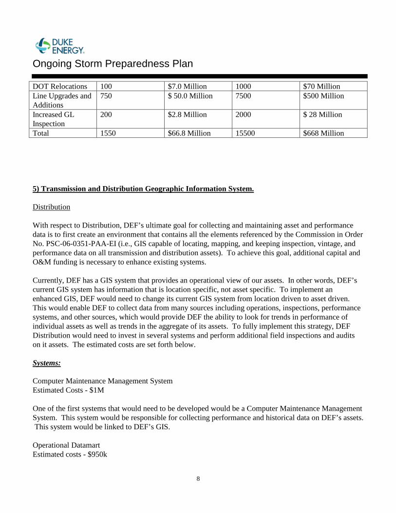
Ongoing Storm Preparedness Plan
8
DOT Relocations 100 $7.0 Million 1000 $70 Million Line Upgrades and Additions
750 $ 50.0 Million 7500 $500 Million
Increased GL Inspection
200 $2.8 Million 2000 $ 28 Million
Total 1550 $66.8 Million 15500 $668 Million 5) Transmission and Distribution Geographic Information System. Distribution With respect to Distribution, DEF’s ultimate goal for collecting and maintaining asset and performance data is to first create an environment that contains all the elements referenced by the Commission in Order No. PSC-06-0351-PAA-EI (i.e., GIS capable of locating, mapping, and keeping inspection, vintage, and performance data on all transmission and distribution assets). To achieve this goal, additional capital and O&M funding is necessary to enhance existing systems.
Currently, DEF has a GIS system that provides an operational view of our assets. In other words, DEF’s current GIS system has information that is location specific, not asset specific. To implement an enhanced GIS, DEF would need to change its current GIS system from location driven to asset driven. This would enable DEF to collect data from many sources including operations, inspections, performance systems, and other sources, which would provide DEF the ability to look for trends in performance of individual assets as well as trends in the aggregate of its assets. To fully implement this strategy, DEF Distribution would need to invest in several systems and perform additional field inspections and audits on it assets. The estimated costs are set forth below.
Systems: Computer Maintenance Management System Estimated Costs - $1M One of the first systems that would need to be developed would be a Computer Maintenance Management System. This system would be responsible for collecting performance and historical data on DEF’s assets. This system would be linked to DEF’s GIS. Operational Datamart Estimated costs - $950k
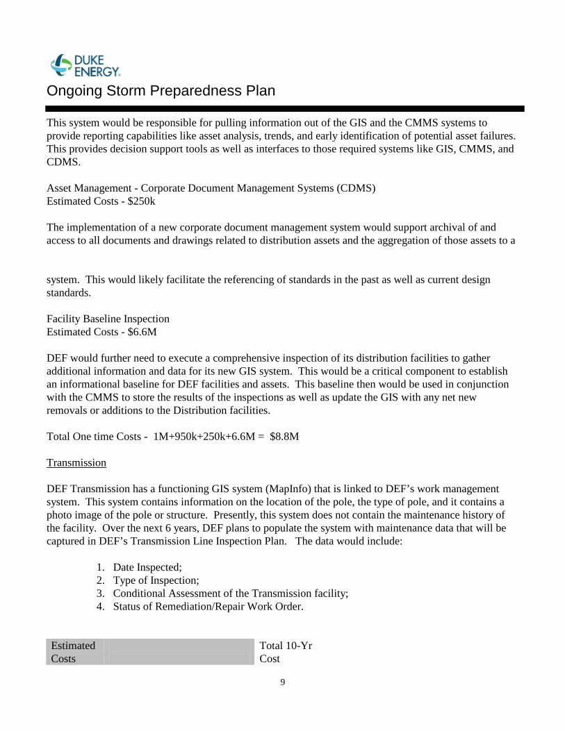
Ongoing Storm Preparedness Plan
9
This system would be responsible for pulling information out of the GIS and the CMMS systems to provide reporting capabilities like asset analysis, trends, and early identification of potential asset failures. This provides decision support tools as well as interfaces to those required systems like GIS, CMMS, and CDMS. Asset Management - Corporate Document Management Systems (CDMS) Estimated Costs - $250k The implementation of a new corporate document management system would support archival of and access to all documents and drawings related to distribution assets and the aggregation of those assets to a system. This would likely facilitate the referencing of standards in the past as well as current design standards. Facility Baseline Inspection Estimated Costs - $6.6M DEF would further need to execute a comprehensive inspection of its distribution facilities to gather additional information and data for its new GIS system. This would be a critical component to establish an informational baseline for DEF facilities and assets. This baseline then would be used in conjunction with the CMMS to store the results of the inspections as well as update the GIS with any net new removals or additions to the Distribution facilities. Total One time Costs - 1M+950k+250k+6.6M = $8.8M Transmission DEF Transmission has a functioning GIS system (MapInfo) that is linked to DEF’s work management system. This system contains information on the location of the pole, the type of pole, and it contains a photo image of the pole or structure. Presently, this system does not contain the maintenance history of the facility. Over the next 6 years, DEF plans to populate the system with maintenance data that will be captured in DEF’s Transmission Line Inspection Plan. The data would include:
1. Date Inspected; 2. Type of Inspection; 3. Conditional Assessment of the Transmission facility; 4. Status of Remediation/Repair Work Order.
Estimated Costs
Total 10-Yr Cost
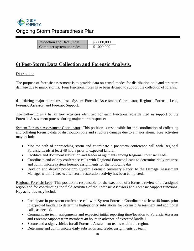
Ongoing Storm Preparedness Plan
10
Inspection and Data Entry $ 2,000,000 Computer system upgrades $1,000,000
6) Post-Storm Data Collection and Forensic Analysis. Distribution The purpose of forensic assessment is to provide data on causal modes for distribution pole and structure damage due to major storms. Four functional roles have been defined to support the collection of forensic data during major storm response; System Forensic Assessment Coordinator, Regional Forensic Lead, Forensic Assessor, and Forensic Support. The following is a list of key activities identified for each functional role defined in support of the Forensic Assessment process during major storm response: System Forensic Assessment Coordinator- This position is responsible for the coordination of collecting and collating forensic data of distribution pole and structure damage due to a major storm. Key activities may include:
• Monitor path of approaching storm and coordinate a pre-storm conference call with Regional Forensic Leads at least 48 hours prior to expected landfall.
• Facilitate and document substation and feeder assignments among Regional Forensic Leads. • Coordinate end-of-day conference calls with Regional Forensic Leads to determine daily progress
and communicate system forensic assignments for the following day. • Develop and deliver post-storm System Forensic Summary Report to the Damage Assessment
Manager within 2 weeks after storm restoration activity has been completed. Regional Forensic Lead- This position is responsible for the execution of a forensic review of the assigned region and for coordinating the field activities of the Forensic Assessors and Forensic Support functions. Key activities may include:
• Participate in pre-storm conference call with System Forensic Coordinator at least 48 hours prior to expected landfall to determine high-priority substations for Forensic Assessment and additional calls, as needed.
• Communicate team assignments and expected initial reporting time/location to Forensic Assessor and Forensic Support team members 48 hours in advance of expected landfall.
• Secure and assign vehicles for all Forensic Assessment teams within the region. • Determine and communicate daily substation and feeder assignments by team.
Ongoing Storm Preparedness Plan
11
• Establish protocols and timelines with Forensic Assessment teams within the region for communicating daily start, stop, and safety check-in times and notify system Damage Assessment Manager and System Forensic Coordinator if communication is not established with teams as expected.
• Participate in end-of-day conference calls with System Forensic Coordinator and other Regional Forensic Leads to determine the system-wide status of Forensic Assessment and assign assessment locations for the following day.
• Provide complete Region Substation Forensic Summary Reports to System Forensic Coordinator within 1 week after storm restoration activity has been completed.
Forensic Assessor- This position is responsible for the resources necessary to conduct the Forensic Assessment in the field, including the direct supervision of an assigned Forensic Support team member. Key activities may include:
• Be proficient in the data collection process and procedure necessary to conduct Forensic Assessment.
• Prepare field kit upon initial notification of assignment from Regional Forensic Lead. • Confirm daily Forensic Assessment assignment with Regional Forensic Lead and confirm
protocols and timelines with for communicating daily start, stop, and safety check-in times. • Initiate contact with assigned Forensic Support team member and provide just-in-time refresher of
expectations as required. • Conduct pre-trip inspection with Forensic Support prior to departing local Operation Center to
ensure all materials and resources are available and that the vehicle is in safe working order. • Conduct pre-job briefing before each inspection. • Conduct field Forensic Assessment of assigned substations and/or feeders and collect required data
for each pole identified as damaged or in need of repair. • Report daily observations and status update to Regional Forensic Lead as assigned. • Complete and submit hardcopy checklist to Regional Forensic Lead for each pole identified as
damaged or in need of repair no later than 2 days after restoration activity has been completed. Forensic Support- This position will provide field support to the Forensic Assessor in the collection of required data during Forensic Assessment in the field. Key activities may include:
• Participating in pre-job briefings. • Safe operation of assigned passenger vehicle. • Cataloguing time, location, and other required data for each pole identified as damaged or in need
of repair. • Assisting in the preparation of summary reports for use by the Regional Forensic Lead.
Ongoing Storm Preparedness Plan
12
DEF has implemented the Forensic Assessment process for the upcoming 2006 storm season. Transmission Field Data Collection DEF Transmission will establish a contract with an engineering/survey firm that will require the firm to provide resources immediately after a storm event. This contractor will collect detailed post storm data necessary to perform storm damage and forensic analysis. This data will include:
1. Photographs of the failed facility; 2. Conditional assessment of the failed facility;
3. Sample collection of any failed components; and 4. Date stamps, name plate data.
Maintenance/GIS Data The balance of needed data will be collected from the GIS data base and will include:
1. Location of the facility (GPS coordinates); 2. Type and design of the facility; 3. Facility vintage; and 4. Maintenance history of facility.
Data Reduction The above data will be provided to a consultant. Using the storm data that was collected from the field collection process, data contained in the GIS data base, and available weather data, a forensic analysis will be performed in order to correlate storm intensity, design standards, maintenance history, geographic locations, materials, facility types, and vintage. From this analysis, the consultant will make recommendations storm hardening improvements. Estimated Costs Estimated costs will be based on the amount of storm damage that occurs as a result of a single storm in one year. The estimated costs listed below are based upon the illustrative assumption of 100 transmission structures that are damaged and require analysis.
Ongoing Storm Preparedness Plan
13
Costs Total 10-Yr Cost
Field Data Collection $5 Million GIS Data Collection $2 Million
Data Reduction and Recommendations
$2 Million
Total Cost $9 Million 7) Collection of Outage Data Differentiating Between the Reliability Performance of Overhead and Underground Systems. DEF will collect information to determine the percentage of storm caused outages on overhead systems and underground systems. Some assumptions are required when assessing the performance of overhead systems versus underground systems. For example, underground systems are typically protected by overhead fuses. DEF will provide for these factors in its analysis. DEF has an internal hierarchy in its Outage Management System (OMS) that models how all of its facilities are connected to each other. This information provides the connection to the feeder breaker down to the individual transformer. DEF’s Customer Service System (CSS) captures which customer is tied to what individual transformer. DEF’s Geographical Information System (GIS) provides several sets of data and information points regarding DEF’s assets. DEF will use these systems to help analyze the performance of the following types of assets: Breakers Electronic Reclosers Fuses Hydraulic Reclosers Interrupters Motor Operated Switches OH Conductors OH Transformers Primary Meters Switch Gear Fuses Sectionalizers Services Switches Terminal Pole Fuses Under Ground Conductors Under Ground Transformers
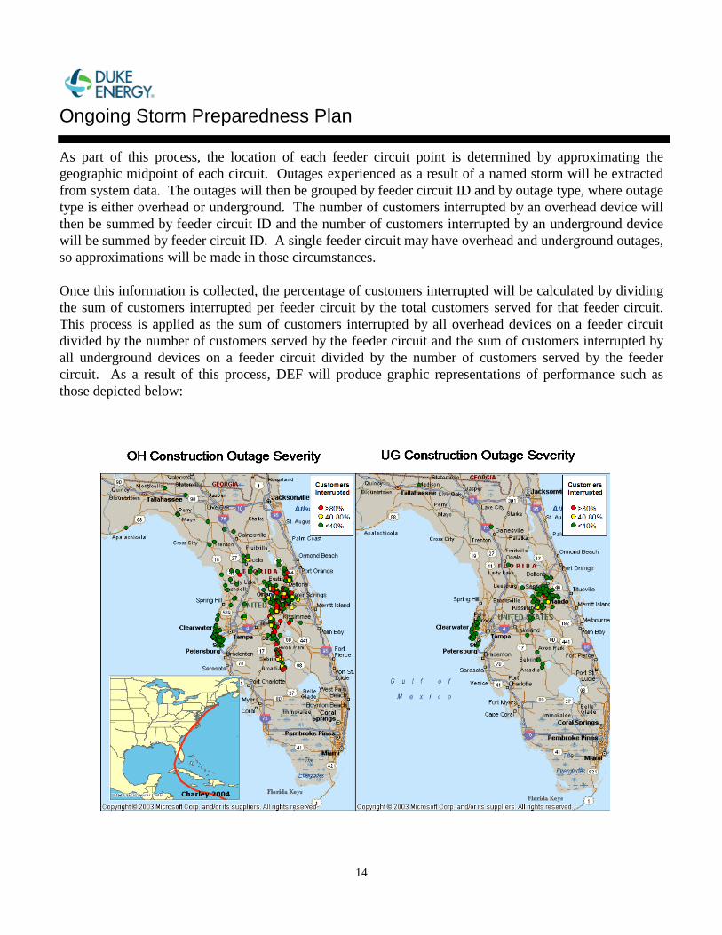
Ongoing Storm Preparedness Plan
14
As part of this process, the location of each feeder circuit point is determined by approximating the geographic midpoint of each circuit. Outages experienced as a result of a named storm will be extracted from system data. The outages will then be grouped by feeder circuit ID and by outage type, where outage type is either overhead or underground. The number of customers interrupted by an overhead device will then be summed by feeder circuit ID and the number of customers interrupted by an underground device will be summed by feeder circuit ID. A single feeder circuit may have overhead and underground outages, so approximations will be made in those circumstances. Once this information is collected, the percentage of customers interrupted will be calculated by dividing the sum of customers interrupted per feeder circuit by the total customers served for that feeder circuit. This process is applied as the sum of customers interrupted by all overhead devices on a feeder circuit divided by the number of customers served by the feeder circuit and the sum of customers interrupted by all underground devices on a feeder circuit divided by the number of customers served by the feeder circuit. As a result of this process, DEF will produce graphic representations of performance such as those depicted below:
Ongoing Storm Preparedness Plan
15
DEF will also collect available performance information as apart of the storm restoration process via servicemen in the field, such as: Restore time; Cause code; Observations and comments; Failed device name; Failed device size; Failed device type; Failed device phase; and Failed device location. The implementation of a new GIS system discussed above would enhance DEF’s ability to collect data relevant to asset performance, and DEF would use this data to analyze and compare the performance of its overhead and underground systems. 8) Increased Utility Coordination With Local Governments. This part of the Plan addresses increased coordination with local governments to enhance DEF’s ability to prepare for and respond to storms and other severe weather events. DEF’s goal is to provide excellent customer service and collaboration with local governments before, during, and after emergencies through organization, commitment, strong relationships, the provision of resources, and communication and feedback mechanisms. Through a collaborative partnership with local governments, DEF can take advantage of the mutual interest in excellent response to communities through year-round dialogue and planning. Specifically, DEF will focus on the following in implementing this plan in conjunction with local governments: • Identify opportunities throughout the year to improve preparedness on both the part of the utility and
the public taking advantage of government’s local knowledge and existing organization. • Develop enhanced organization and planning to improve readiness. • Educate the public on proper storm preparation and restoration actions. • Provide local governments with the support needed to facilitate the coordination of outage restoration
in a safe and efficient manner. • Provide local governments with ongoing information and updates in advance of, during and after
storm events to assist them with their local storm preparation and restoration efforts including informing the public.
• Assist in the resolution of local governmental issues and concerns related to storm and emergency situations.
Ongoing Storm Preparedness Plan
16
In order to meet the requirements of FPSC Order No. PSC-06-0351-PAA-EI, DEF has established an internal team focused on local governmental coordination activities. These activities include dedicated resources, training, continuous coordination with government, storm preparation, storm restoration and an EOC program. a) Staffing and Training
A cross-functional internal team has been established utilizing personnel from numerous areas including community relations, regulatory affairs, and account management. The role of the team will be to develop and implement initiatives focused on governmental coordination and to participate in both internal and external storm preparation planning activities. • Staffing – The governmental coordination team consists of approximately 70 employees throughout
DEF’s service territory. Each member is assigned to a specific role. Job descriptions have been developed for each role. These will be updated annually to meet current needs and requirements. Below are the roles for this team and the approximate number of employees in each role.
Government Coordination Roles Storm Coordinator (1) State EOC Coordinator (1)
Community Relations Manager – CRM (6) Manager, CIG Accounts (1) Back Up CRM/Support (23) EOC Representative (28) Operations Center Liaison (10)
Members of the team are responsible for familiarizing themselves with their job description, participating in annual training and general readiness for storm duty as required. In addition, certain members will work with assigned communities throughout the year to identify opportunities for enhanced coordination and support local community storm preparation activities.
Annually a system-wide internal storm drill will be conducted in which members of the team will participate. The State EOC Coordinator will work with state agencies to coordinate the company’s participation in the annual state storm drill.
Staffing scenarios are created to simulate different storm impacts and staffing assignments to support each impact scenario. Personnel are flexible to shift to positions throughout the state as needed. This supports initiatives to coordinate with local government including emergency management organizations throughout the year (i.e. community storm drill activities, updating EOC infrastructure restoration priority account lists and EOC contact lists).
Ongoing Storm Preparedness Plan
17
Training is been developed for all team members. Training will be conducted on an annual basis in multiple locations throughout the system and will include the following elements:
Overview of government coordination organization Storm assignments and roles Job requirements Material and resource requirements EOC crew management module NIMS training
In addition to classroom training, an internal electronic site is being developed to house information and resources that are accessible by all team members before, during, and after storm events. This site will include, but not be limited to, the information listed below.
Training Presentations and Materials Storm Job Descriptions Staffing Priority List Team Member Lists/Contact Info Maps, Location/Contact Information Territorial Maps Government/Agency Contact Information Storm Staffing Scenarios Calendar of Activities Storm Organization Chart
b) On Going Coordination Throughout the year, company representatives will work with local government officials and agency representatives to enhance the flow of information and to identify coordination opportunities. Coordination opportunities fall into several categories – storm related activities, vegetation management programs, undergrounding programs, and other coordination efforts. • Storm Related Activities
Representatives from DEF will participate in local storm workshops and expositions throughout DEF’s service territory. In many cases, DEF will act as presenters or co-sponsor for these events. These events will occur in each region of DEF’s service territory. In addition, DEF will hold workshops and other coordination meetings with local officials and agencies to educate on restoration programs, develop coordination plans, exchange feedback and generally enhance communication between organizations. Some key events scheduled for 2006 are listed below. DEF is taking steps to enhance public information through the media. Among a number of
activities, DEF will be participating as a panelist in hurricane preparedness town hall-type meetings forums in the Tampa and Orlando television markets. The programs are designed to
Ongoing Storm Preparedness Plan
18
educate the public and will include representatives from local government emergency management, the Red Cross, and FEMA.
DEF is scheduled to participate in EOC Coordination activities in most counties served including
events and briefings in the following counties:
Pinellas County Orange County Columbia County Gulf County Highlands County Pasco County Volusia County
DEF is scheduled to participate in State-sponsored events:
Governor’s Hurricane Conference State Storm Drill
DEF Sponsored events: South Coastal Community Storm Meeting and Expo (Pinellas and Pasco Counties) Duke Energy’s 911 First Responders Storm and Safety Expo (Winter Garden Operation Center – covering Orange, Osceola, Seminole, Lake, Volusia, Gilchrist, Sumter and Polk) DEF is incorporating into its SCORE workshops for commercial, industrial and governmental customers a segment on hurricane preparedness and DEF restoration processes.
• Vegetation management coordination program
It has become essential to implement programs designed to improve coordination with communities regarding vegetation management. Not only will these activities support efforts to improve overall reliability improvement programs, but they will also support storm preparation and restoration activities. DEF has completed the development of a community vegetation management education program. This program is designed to:
Ensure that all Duke Energy customers will have received some form of vegetation management
education through community outreach, events, web site information, advertising and other communication mechanisms.
Ongoing Storm Preparedness Plan
19
Improve relationships with local governments, offering successful vegetation programs in their communities.
Launch a Radio/Public Service Announcement Campaign in 2006 that will reach more than 30% of the Duke Energy market.
Distribution of information in 2006 on vegetation management that will reach more than 30% of the Duke Energy market.
Vegetation programs and events in Duke Energy communities in Florida.
• Undergrounding Programs
The impact of hurricanes in Florida since 2004 has renewed local government interest in burying overhead power lines. In an effort to work with communities to address this renewed interest in undergrounding their utilities, DEF is enhancing its programs in this area and has seen a marked increase in interest in the programs. DEF has ongoing undergrounding partnerships with a number of communities. Within these projects, the company acts as project manager and facilitates coordination not only with the municipality but also with other utilities (i.e., cable, TV). Local government underground cost recovery tariff - DEF is in the process of revising its local government underground cost recovery tariff. This tariff allows local governments to recover the CIAC portion of the cost for underground projects through electric bills of customers within the local government’s jurisdiction. The revised tariff will increase government flexibility in managing the cost of underground projects. As part of this program, the company is developing the concept of a secure external portal designed to assist governments in managing their underground projects utilizing the tariff.
• Street lighting repair program
DEF has implemented an improved program for customers to report street light outages to enhance the repair process. As part of the effort, we are coordinating with local government to communicate the improved process and encourage better utilization by government of improved reporting mechanisms. Communications have been sent to all city and county governments.
• Other coordination activities
DEF continues to develop opportunities to enhance relationships and communication with local government for improved service, reliability and restoration efforts. For example, the company plans to send out a communication to each local government within our service territory to encourage a link to the company’s storm information web site be place on the community web site.
c) Plan implementation during storm events
Ongoing Storm Preparedness Plan
20
When a major storm event occurs, the local government coordination storm plan will be executed. All team members will participate in pre-storm planning activities and receive assignments to specific regions and roles. The following is a high-level list of actions that will be performed by the team intended to provide excellent execution of community restoration activities and support of local government efforts.
• Communications with local government officials, agencies and key community leaders prior to the storm event notifying of DEF storm readiness activities and status.
• Ongoing communications to government officials, agencies and key community leaders providing updates of outage and storm restoration efforts of the company.
• Oversight of EOC Representatives (State) assigned to state and local EOCs. • Provide updates and information for coordination purposes to internal leadership and operation
personnel within the company. • Obtain the Governor’s Executive Order and distribute to DEF Logistics personnel for logistical
purposes. • Prepare DOT Waivers and communicate with DOT SEOC personnel (ESF 16) to expedite arrival
of out-of-state crews prior to entry into the State of Florida. • Prepare Aviation Waivers and obtain approvals from ESF 1 & ESF 3 (DOT & Public Works). • Coordinate with DEF Storm Centers for the exchange of accurate information pertaining to
restoration efforts before, during and after a major storm. • Communicate with local officials regarding power outage data for the county as well as restoration
efforts. d) Emergency Operation Center (EOC) Plan DEF has created and will be implementing a specific program for the management of restoration activities in coordination with local government at state and county EOCs during storm events. The specific role of the EOC Representative has been created to engage with EOC management on pre-storm planning and during storm events. The company has also assigned specific personnel to represent the company and to be stationed in a number of key EOCs throughout the storm event.
The primary responsibility of the EOC Representative is to work with the EOC personnel to establish current priorities for restoration, communicate this information to appropriate operating center personnel and ensure EOC priorities are worked successfully. The EOC Representative and other team members are responsible for establishing contact with assigned EOC and to update storm restoration infrastructure priority lists prior to the beginning of the storm season.
Ongoing Storm Preparedness Plan
21
Pre-storm duties: Work with local governments to update specific city/county and EOC priorities (e.g.
designated hospitals, shelters, traffic lights, essential water treatment facilities and lift stations, etc.) and develop prioritized account list for each county.
Create list of all governmental facilities in the County including responsible operating center, substation, and feeder.
Review DEF procedures with EOC staff and establish working relationship and rules. Work internally with operations personnel to establish EOC priority work flow. Provide feeder maps or outage information for the County for use at the EOC. Obtain a street level utility territory map for the County.
Assure a network connection that will accommodate a Duke Energy computer exists at the EOC.
Attend scheduled meetings as the storm approaches. Participate in software training at EOCs.
Duties during major storm event: Organize and report “911” type issues to Dispatch Advise company of the need for press briefings or public official meetings Attend scheduled EOC meetings Provide regular briefings on DE progress and deliver key communications to EOC personnel Communicate internally for the exchange of timely and accurate information
Duties after major storm: Attend scheduled EOC debriefing meetings Responsible for “break-down” of DEF area in EOC facility
9) Collaborative Research on Effects of Hurricane Winds and Storm Surge. DEF will support a collaborative effort to conduct research and development (R&D) on the effects of hurricane winds and storm surge to the electrical system of Florida. The company also will support the leadership of the R&D effort to be facilitated through a centrally coordinated effort managed by an entity within the state that can draw from various universities and research organizations not only in Florida, but across the United States as well. DEF believes the necessary leadership to serve as the R&D coordinator is available from the Public Utility
Ongoing Storm Preparedness Plan
22
Research Center (“PURC”) in the Warrington College of Business Administration at the University of Florida. PURC is a long-standing research organization with a strong working relationship among the investor-owned utilities, cooperatives and municipals. Therefore, PURC is well positioned to either provide or secure the resources necessary for the R&D effort envisioned by the Commission.
PURC’s position within the university community of the state and the nation allows the organization to draw from a number of resources otherwise unknown to utilities. Therefore, by coordinating the overall R&D initiative, unnecessary duplication of effort and superfluous spending should be avoided. However, if a utility has a need for a specific type of research to determine a solution to its unique problem, the utility is not hindered from engaging in independent research on its own through a local university or research organization other than PURC. Estimated Costs and Timeline
DEF believes the collaborative research plan described above meets the intent of the Commission. The cost for this initiative will be determined by the extent and duration of R&D requested by the IOUs.
10). Natural Disaster Preparedness and Recovery Program. Please see Attachments A, B and C to this Plan for DEF’s Preparedness and Recovery Programs.
• Attachment A – Department Storm Plans • Attachment B – Transmission Department Corporate Storm Plan • Attachment C – Distribution & Transmission Storm Plans - Florida

ATTACHMENT S
AUTHORIZED COPY
MNT-TRMX-00176 Rev. 6 (11/11) Page 1 of 12
Document title
Transmission Vegetation Management Program Document number
MNT-TRMX-00176 Applies to: Transmission Operations & Planning Department – Carolinas and Florida Keywords: maintenance; transmission – maintenance line 1.0 Introduction
Progress Energy Transmission employs an Integrated Vegetation Management Program (IVMP) that combines various components to manage the growth of vegetation on the electric transmission utility right of way (ROW). Through the use of different, integrated methods, the optimum results (reliability, etc.) occur reducing the need to employ reliability-based trimming/removal and danger tree cutting. Progress Energy Transmission utilizes easements, permits and/or company owned lands for the right of way on which the transmission lines are constructed. The routine inspection and maintenance of the right of ways (ROW) are extremely important for the safety of the public and the personnel that are responsible for the operation/maintenance of the transmission lines. Maintaining right of ways in accordance with established procedures results in a high level of transmission line reliability.
2.0 Program Policies, Procedures, Components and Specifications (FAC-003 R1)
2.1 Program Objectives
Ensure the reliability of the transmission system by minimizing vegetation related interruptions, while maintaining compliance with regulatory, environmental and safety requirements/standards.
2.2 Philosophy
Our philosophy is based upon employing the proper, most economical vegetation management techniques to ensure the effectiveness of our program in a wide variety of environments. This is achieved through communication, continuous learning and assessing best management practices throughout the industry.
The Transmission Vegetation Management Program (Document No. MNT-TRMX-00176) was provided to the Commission by DEF’s predecessor, Progress Energy Florida, Inc. (“PEF”) in its 2012 Annual Reliability Report. DEF confirms there are no substantive changes to the document.
AUTHORIZED COPY
MNT-TRMX-00176 Rev. 6 (11/11) Page 2 of 12
2.3 Program Scope
The visual inspection and appropriate maintenance of transmission line right of ways comprise the Transmission Vegetation Management Program. Inspections (periodic aerial and as needed ground patrols) are performed to monitor vegetation growth, right of way contractor effectiveness and encroachments within the right of way. Maintenance activities may include any of the following: re-clearing vegetation (mechanical clearing, hand cutting and herbicide application), tree trimming/removal, danger tree cutting and encroachment licensing/removal. All transmission lines at voltages of 200 KV and higher will maintain 100% compliance with the MNT-TRMX-00176 specifications and cycle frequencies. All transmission lines at voltages less than 200KV will utilize MNT- TRMX-00176 as a standard and apply appropriate IVM methods as required to ensure the reliability of the line.
2.4 Program Work Components
All work performed shall be in accordance with ANSI, OSHA and other applicable safety requirements, laws and Progress Energy guidelines. The following describes the various components that are utilized in the Progress Energy Transmission’s Integrated Vegetation Management Program.
Right of way re-clearing (using mechanical equipment – e.g., rotary mowers, Kershaw, Hydro-Ax, etc.) - All of the wooded sections of the right-of-way are to be re-cleared with mechanical equipment, where possible, to the full width as noted in a detail description. All undergrowth is to be cut within six (6) inches of the ground. All vines on poles and brush around poles in fields are to be cut and removed out of cropped areas. Cut all leaning trees that have been pulled into the right-of-way by storms. All brush cut from stream banks or drainage ditches must be removed from streams and ditches so as not to impede the flow of water. When run ways are cut through existing canals, the canal must be restored to original condition allowing drainage to continue as it did before our operation. Vista screens and trimmed trees are not to be cut during re-clearing operations without specific instructions from Company representative. Right of way re-clearing (hand-cutting) - All of the wooded sections of the right-of-way that cannot be re-cleared with mechanical equipment are to be hand cut to the full width as noted in a detail description. All undergrowth is to be cut within six (6) inches of the ground or current water level. All vines on poles and brush around poles in fields are to be cut and removed out of cropped areas. Cut all leaning trees that have been pulled into the right-of-way by storms. All brush cut from stream banks or drainage ditches must be removed from streams and ditches so as not to impede the flow of water. Vista screens and trimmed trees are not to be cut during re-clearing operations without specific instructions from a Progress Energy representative.
The Transmission Vegetation Management Program (Document No. MNT-TRMX-00176) was provided to the Commission by DEF’s predecessor, Progress Energy Florida, Inc. (“PEF”) in its 2012 Annual Reliability Report. DEF confirms there are no substantive changes to the document.

AUTHORIZED COPY
MNT-TRMX-00176 Rev. 6 (11/11) Page 3 of 12
Right of way re-clearing (herbicides) – Where appropriate, the primary method of vegetation control on transmission right of ways may be established as, or converted to, the use of herbicides. Herbicides may also be applied on a case by case basis on areas of line right of ways that cannot be effectively, or efficiently, mowed or hand-cut. The application of herbicides on Transmission ROW shall be in accordance with procedure EVC-EDGC-00001 (Herbicide Usage on Rights-of-Way Energy Delivery Carolinas only) and all applicable TVM specifications.
Tree removal/trimming - All trees requiring removal/trimming should be removed or trimmed so as to obtain sufficient clearance to prevent a hazard to operations for the removal/trimming cycle. As noted in right-of-way use guidelines and many easement documents, vegetation that matures at a height of greater than 12’ may not be planted in the right-of-way and, if planted without written approval, is subject to potential removal during future maintenance activities. Existing vegetation within the ROW that will reach a height of more than 12’ at maturity will be evaluated for removal during maintenance by Progress Energy representatives based on line or site specific parameters, Progress Energy arboricultural practices/principles and the rights granted to Progress Energy via underlying easements, permits or other legal documents. In improved areas such as yards, landscaping etc., the property owner may be notified of the planned tree removal work via direct contact, door hangers or other methods as appropriate for the site/situation specific circumstances.
Side-trimming – Trees within and along the edge of the right-of-way will be targeted for removal, and trees outside of the right-of-way with growth potential within the right-of-way will be side-trimmed at a minimum (some may require removal if side-trimming is not adequate) to meet clearance requirements. These trees or limbs, due to their height and location, have the potential to make contact with, or be in close proximity to, the conductor due to reasonably expected conductor movement (i.e. conductor blowout). Off right of way tree cutting – Off right of way trees are those trees located outside the defined right of way width. These trees, due to their height if they were to fall could make contact with the conductor or fall to within five feet of the outermost conductor, grow into the conductor or due to conductor blowout could make contact with the conductor. All trees cut are to be cut according to MNT-TRMX-00193 (TVM: Off Right of Way Tree Cutting Guidelines). Danger tree cutting – Danger trees are those trees located inside or outside the designated right of way that are in decline/diseased, have structural defects, leaning towards the right of way or are dead. These trees, due to there height if they were to fall could make contact with the conductor or fall to within five feet of the outermost conductor. These trees should be inspected and assessed thoroughly for structural integrity before climbing is performed. When the safety of the crew is at risk if the tree is climbed, alternate mechanical or other methods shall be utilized to perform the removal safely.
The Transmission Vegetation Management Program (Document No. MNT-TRMX-00176) was provided to the Commission by DEF’s predecessor, Progress Energy Florida, Inc. (“PEF”) in its 2012 Annual Reliability Report. DEF confirms there are no substantive changes to the document.
AUTHORIZED COPY
MNT-TRMX-00176 Rev. 6 (11/11) Page 4 of 12
2.4.1 Program Component Frequency Targets
The actual frequency for specific facilities may vary significantly from the target frequency based on the integrated program components that are being employed and on site/facility specific factors (such as - but not limited to: indigenous vegetation, easement/permit width and rights, construction type, voltage, IVM activities, environmental restrictions, regulatory requirements, etc.) Right of way maintenance frequency intervals for program component tasks are identified below. These frequency intervals will be used as the initial scheduling targets to determine the calendar year in which the work will be scheduled.
Task PE Carolinas PE Florida
2.4.1.1 Right of Way 1. Re-clearing (mechanical) 36 months 48-60 months 2. Re-clearing (hand-cutting) 36 months 48-60 months 3. Re-clearing (herbicides) 36 months 48 months 4. Tree removal/trimming 36 months 48-60 months 5. Side-trimming 36-72 months 48-60 months 6. Off-R/W Tree Cutting As Needed* As Needed*
* Reliability-based danger tree cutting is performed as needed when danger trees are identified.
2.5 Work Specifications and Procedures
2.5.1 Work Specifications
Standards for specific work will be developed for all work practices and incorporated into contract documents for each project or work activity. These standards/specifications will incorporate ANSI-300 and ANSI-Z133 as appropriate.
2.5.2 Off Right-of-Way Tree Cutting Standards found in MNT-TRMX-00193 (TVM: Off Right of Way Tree Cutting Guidelines).
The Transmission Vegetation Management Program (Document No. MNT-TRMX-00176) was provided to the Commission by DEF’s predecessor, Progress Energy Florida, Inc. (“PEF”) in its 2012 Annual Reliability Report. DEF confirms there are no substantive changes to the document.
AUTHORIZED COPY
MNT-TRMX-00176 Rev. 6 (11/11) Page 5 of 12
3.0 Inspections (FAC-003 R1.1)
Aerial patrols will be conducted in accordance with all applicable Progress Energy Safety Rules, OSHA regulations, work practices, and regulatory requirements. Patrols will be conducted with qualified Progress Energy Transmission personnel to look for and document conditions of the following: ROW/Vegetation clearances - encroachments - line equipment - substation equipment. The general guidelines for TVM Aerial Patrol Inspections, reactive work completion and frequencies that impact Right of Way are defined in procedure MNT-TRMX-00195 (TVM Program: Aerial Patrol Inspection Guidelines). When multiple aerial patrols are planned for a calendar year, they will be scheduled across the growing season to ensure that growth issues are detected.
4.0 TVM Clearance Requirements (FAC-003 R1.2)
Progress Energy Transmission vegetation clearance requirements for the TVM program have been established. These clearances comply with the program vegetation clearances requirements of FAC-003. 4.1 Vegetation Clearances Following VM Work (FA-003 R1.2.1)
The vegetation clearances to be achieved at the time of TVM work completion will comply with the following guidelines: 4.1.1 Clearances Achieved at the Time of TVM Work
4.1.1.1 Vegetation Clearance: Floor Growth (vertical)
The vegetation to conductor clearances to be obtained at the time of TVM work completion will use the maximum operating sag of the conductor as the reference point for TVM work for vegetation clearances. The clearance to be obtained at the time of TVM work will use the following criteria: o Clearances to be cut will include the appropriate ‘minimum’ conductor
to vegetation clearances defined in Table 4 or Table 5 (i.e. Clearance 2) of MNT-TRMX-00191 (TVM Program: Vegetation Clearance Tables)
o Clearances will also include distances for vegetation re-growth as defined in Table 3 of MNT-TRMX-00191 (TVM Program: Vegetation Clearance Tables)
o These combined distances are to be obtained at the time of TVM work below the maximum operating sag point of the conductor
o Minimum safe working distances may also impact clearance requirements at the time work is completed as defined in Table 1 or Table 2 of MNT-TRMX-00191 (TVM Program: Vegetation Clearance Tables)
The Transmission Vegetation Management Program (Document No. MNT-TRMX-00176) was provided to the Commission by DEF’s predecessor, Progress Energy Florida, Inc. (“PEF”) in its 2012 Annual Reliability Report. DEF confirms there are no substantive changes to the document.

AUTHORIZED COPY
MNT-TRMX-00176 Rev. 6 (11/11) Page 6 of 12
4.1.1.2 Vegetation Clearance: Side Growth
To ensure side growth and conductor side-swing impacts are limited, the TVM program targets providing vegetation side growth clearance, in support of Clearance 1 requirements, based on the following criteria: o Clearance 1 for side growth TVM work is established based on a
reasonable conductor movement (i.e. conductor blowout) assumption of less of less than 4.1 psf wind loading or equivalent to approximately 40 mph winds (i.e., sub-tropical storm winds)
o For all rated electrical operating conditions, implementation of Clearance 1 will avoid encroachment and maintenance of Clearance2 which is the ‘minimum’ conductor to vegetation clearances as defined in Table 4 or Table 5 of MNT-TRMX-00191 (TVM Program: Vegetation Clearance Tables)
o For cases where Clearance 1 cannot be cut at the time of TVM work, mitigation measure to achieve sufficient clearances will be developed.
4.1.2 Safe Working Clearances
For all vegetation work, the minimum safe working distances defined in Table 1 and Table 2 of MNT-TRMX-00191 (TVM Program: Vegetation Clearance Tables) will be observed.
The majority of all work is normally completed at normal operating (loading/temperature) conditions that ensure the safe working clearances can be observed with no special precautions. When operating conditions and vegetation growth reduce clearances to less than the minimum safe working distances, the work will be rescheduled under the appropriate operating conditions to ensure that safe working clearances can be observed.
4.2 Minimum Vegetation to Conductor Clearances (FA-003 R1.2.2)
The minimum conductor to vegetation clearances, Clearance 2 in FAC-003 (R1.2.2), will be maintained under all rated electrical operating conditions. These clearances are defined in Table 4 and Table 5 of MNT-TRMX-00191 (TVM Program: Vegetation Clearance Tables). The clearances included in these tables were developed and based on Table 5, IEEE 516-2003, phase to ground distances with appropriate altitude correction factors applied.
The Transmission Vegetation Management Program (Document No. MNT-TRMX-00176) was provided to the Commission by DEF’s predecessor, Progress Energy Florida, Inc. (“PEF”) in its 2012 Annual Reliability Report. DEF confirms there are no substantive changes to the document.
AUTHORIZED COPY
MNT-TRMX-00176 Rev. 6 (11/11) Page 7 of 12
5.0 Personnel Qualifications (FAC-003 R1.3)
The following qualifications represent the minimum level of experience and/or education to be hired for the following positions. 5.1 Field Inspector/Right of Way Specialist
Minimum Qualifications:
1. Bachelors Degree in Forestry or related field, or 2 year technical degree with 1
years experience, or 5 years experience in utility vegetation management 2. General understanding of Integrated Vegetation Management techniques 3. Understanding of ANSI Z-133 and A-300 4. Understanding of basic electrical systems and causes of vegetation related
interruptions 5. General knowledge of proper herbicide uses and application methods 6. Must obtain state pesticide applicators license within 1 year, or work under the
direction of an Area Forester 7. Must obtain ISA certification within 1 year, or work under the direction of an Area
Forester
5.2 Lead Forester/Area Forester
Minimum Qualifications:
1. Bachelors degree in forestry or related field and 3 years utility vegetation management experience or 2 year technical degree and 5 years experience in utility vegetation management
2. Working knowledge of Integrated Vegetation Management techniques 3. Knowledge of NERC Standard FAC-003-1 and its requirements for the
Transmission Vegetation Management Program 4. Working knowledge of ANSI Z-133 and A-300 5. Working knowledge of an Integrated Vegetation Management Program including
practical applications of herbicides
6.0 Corrective Action Plan (FAC-003 R1.4)
For all locations (spans) on the transmission system where the minimum vegetation clearances cannot be obtained to meet the target frequency cycle for the program component activity, the location will be documented. The following will provide the documentation for all mitigation sites and reactive work:
Corrective Action Plan– planned/documented vegetation management work that is scheduled more frequently than TVM program standard frequencies to mitigate vegetation-related clearance issues to ensure the reliability of the system.
o Every span that requires maintenance other than the Program Component Frequencies, in paragraph 2.4.1, will be documented and tracked, including the mitigation measures for that location (i.e., shorter frequencies, etc).
The Transmission Vegetation Management Program (Document No. MNT-TRMX-00176) was provided to the Commission by DEF’s predecessor, Progress Energy Florida, Inc. (“PEF”) in its 2012 Annual Reliability Report. DEF confirms there are no substantive changes to the document.
AUTHORIZED COPY
MNT-TRMX-00176 Rev. 6 (11/11) Page 8 of 12
Reactive Work – vegetation related work identified in the field, not previously documented or planned, that requires action before scheduled cycle work to mitigate a potential reliability clearance issue.
o The TVM Program reactive work scheduling and tracking process will track all reactive work assigned and completed by TVM personnel.
7.0 Imminent Threat Communications (FAC-003 R1.5)
During the course of TVM work and inspections, any situation or condition that is observed and deemed to present an imminent threat to the Transmission System shall be reported in accordance with the MNT-TRMX-00192 (TVM: Imminent Threat Communication Procedure).
8.0 Annual Work Plan (FAC-003 R2) An annual work plan for the year will be maintained for each area managed by an area forester. The plan will be developed for each component activity by line or complete line maintenance. The plan will be developed using previous work completion dates, cycle length and based on annual growth cycles. Changes to the annual plan shall be documented with criteria for any changes and mitigation plans. Each area forester shall maintain a file for reportable lines with work completion information and a line completion form for each activity or complete line maintenance.
9.0 Transmission Vegetation Outage Reporting (FAC-003 R3)
On a periodic basis, as defined by the Region Reliability Organization, the TVM Program will report any outage that meets the criteria defined in FAC-003. In addition, the outage reporting will utilize the following criteria for meeting the FAC-003 reporting requirements:
o The general exclusion criteria in the MNT-TRMX-00194 (Transmission Outage Reporting Process)
o Side growth vegetation-related outages resulting from tropical storm or higher winds (40 mph or greater)
o Vegetation-related outages due to human or animal interference, such as: animal severing tree; vehicle contact with tree, removal or digging or moving of vegetation; logging; arboricultural or horticultural or agricultural activities; etc.)
o Vegetation related outages that result from vegetation falling into lines from outside the ROW that result from natural disasters shall not be considered reportable (examples of disasters that create non-reportable outages include, but are not limited to, earthquakes, fires, tornados, hurricanes, landslides, wind shear, major storms as defined either by MNT-TRMX-00194 --- the Transmission Outage Reporting Process, ice storms, and floods)
o Transmission vegetation categories (Attachment A, Attachment B, Attachment C & Attachment D)
The Transmission Vegetation Management Program (Document No. MNT-TRMX-00176) was provided to the Commission by DEF’s predecessor, Progress Energy Florida, Inc. (“PEF”) in its 2012 Annual Reliability Report. DEF confirms there are no substantive changes to the document.
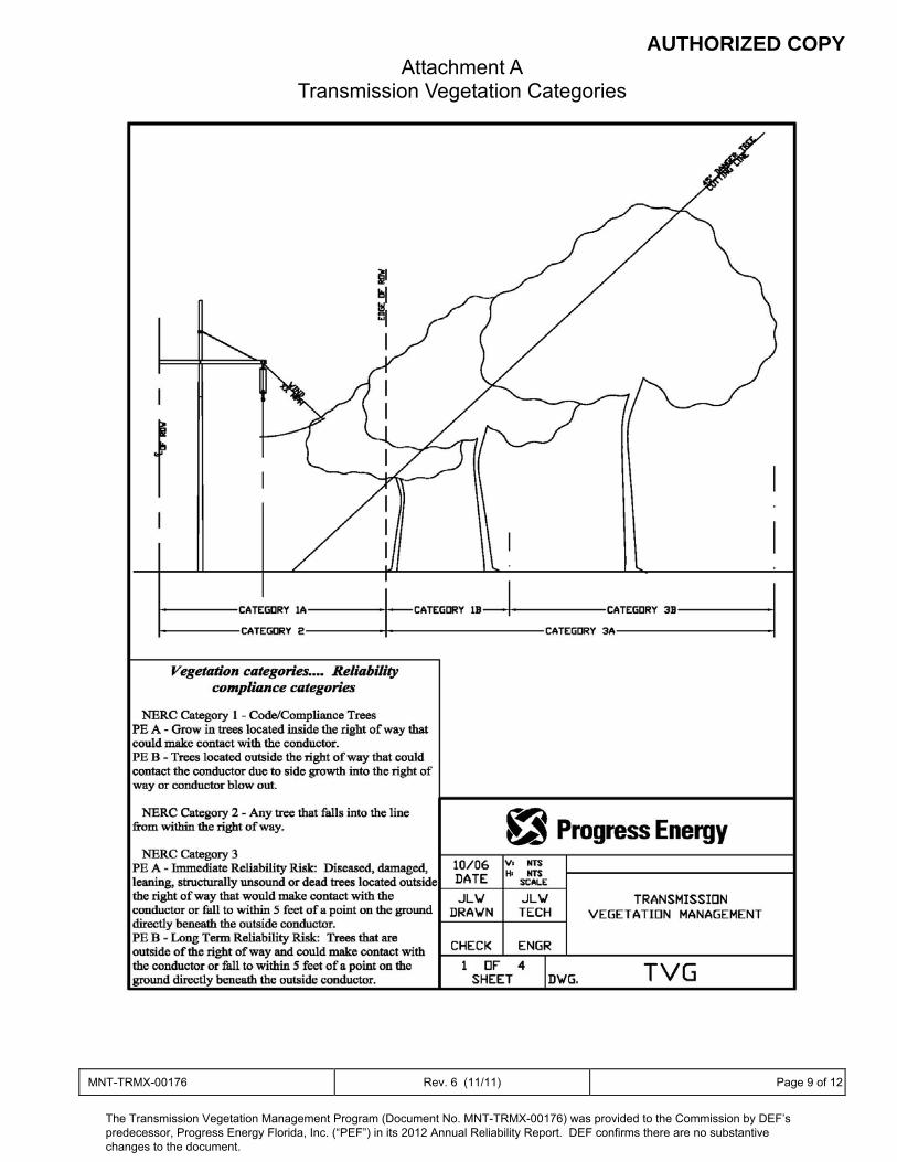
AUTHORIZED COPY
MNT-TRMX-00176 Rev. 6 (11/11) Page 9 of 12
Attachment A Transmission Vegetation Categories
The Transmission Vegetation Management Program (Document No. MNT-TRMX-00176) was provided to the Commission by DEF’s predecessor, Progress Energy Florida, Inc. (“PEF”) in its 2012 Annual Reliability Report. DEF confirms there are no substantive changes to the document.
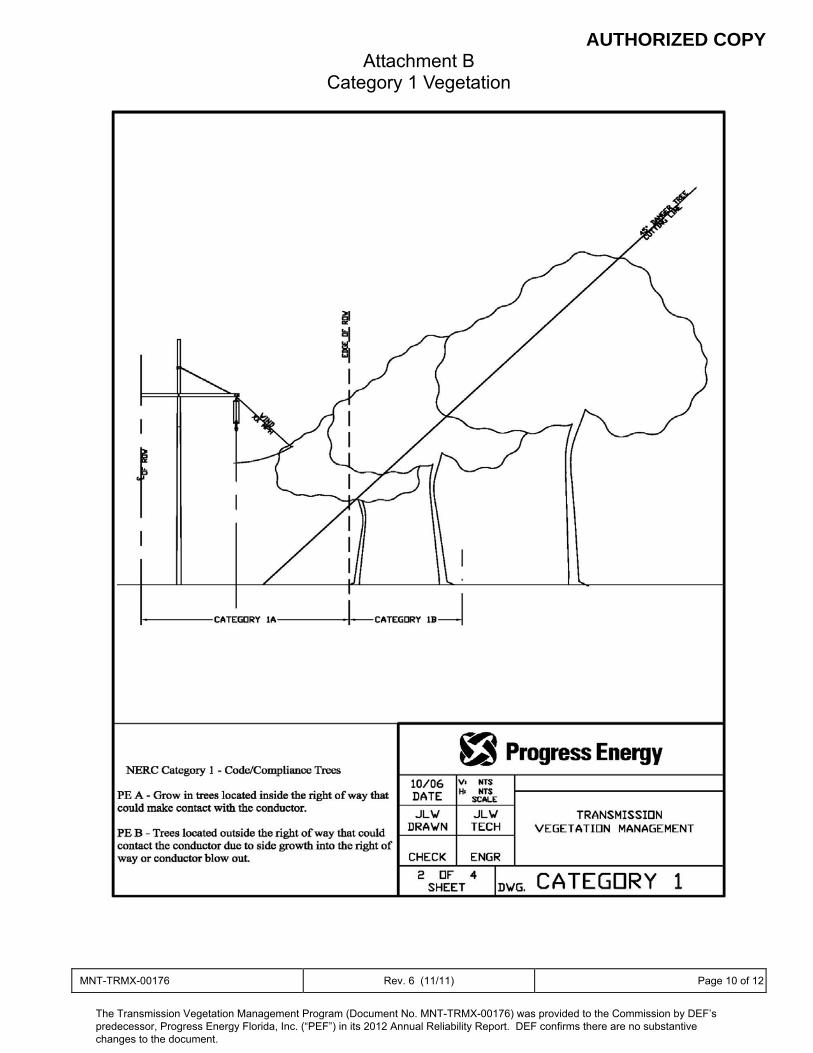
AUTHORIZED COPY
MNT-TRMX-00176 Rev. 6 (11/11) Page 10 of 12
Attachment B Category 1 Vegetation
The Transmission Vegetation Management Program (Document No. MNT-TRMX-00176) was provided to the Commission by DEF’s predecessor, Progress Energy Florida, Inc. (“PEF”) in its 2012 Annual Reliability Report. DEF confirms there are no substantive changes to the document.
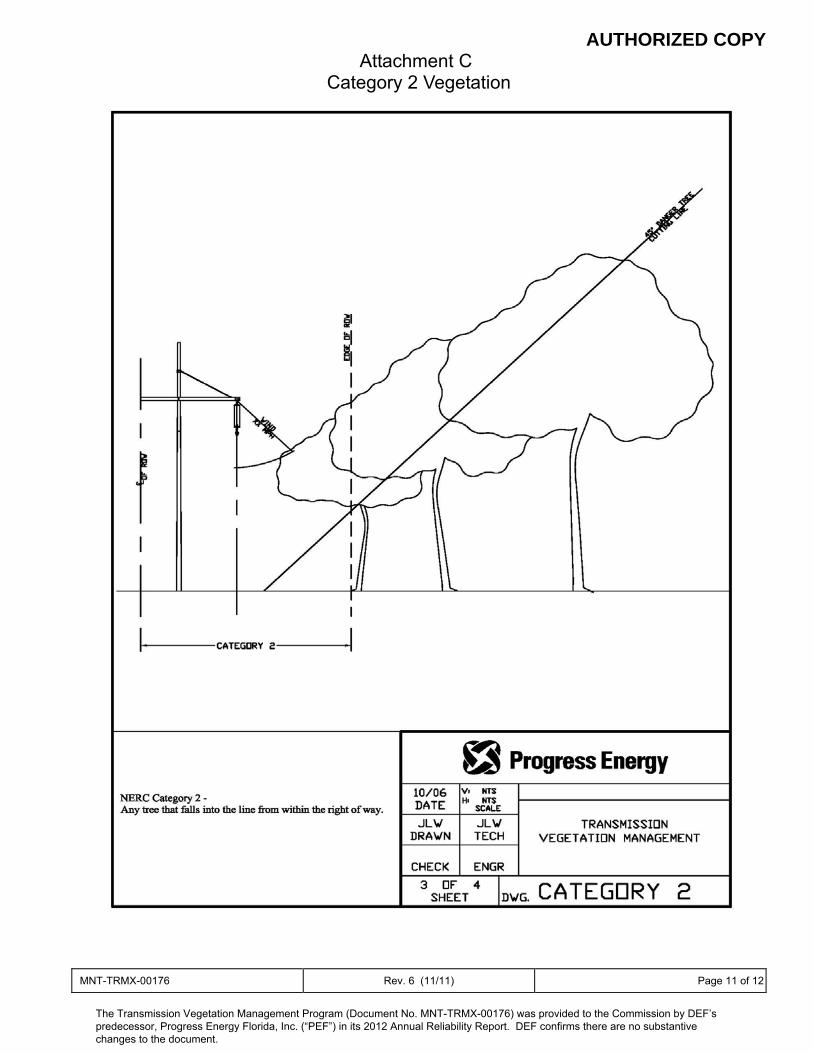
AUTHORIZED COPY
MNT-TRMX-00176 Rev. 6 (11/11) Page 11 of 12
Attachment C Category 2 Vegetation
The Transmission Vegetation Management Program (Document No. MNT-TRMX-00176) was provided to the Commission by DEF’s predecessor, Progress Energy Florida, Inc. (“PEF”) in its 2012 Annual Reliability Report. DEF confirms there are no substantive changes to the document.
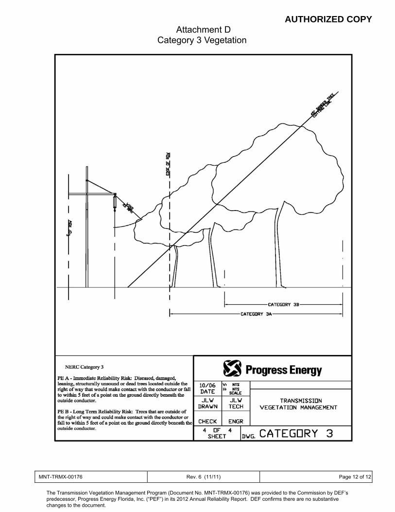
AUTHORIZED COPY
MNT-TRMX-00176 Rev. 6 (11/11) Page 12 of 12
Attachment D Category 3 Vegetation
The Transmission Vegetation Management Program (Document No. MNT-TRMX-00176) was provided to the Commission by DEF’s predecessor, Progress Energy Florida, Inc. (“PEF”) in its 2012 Annual Reliability Report. DEF confirms there are no substantive changes to the document.

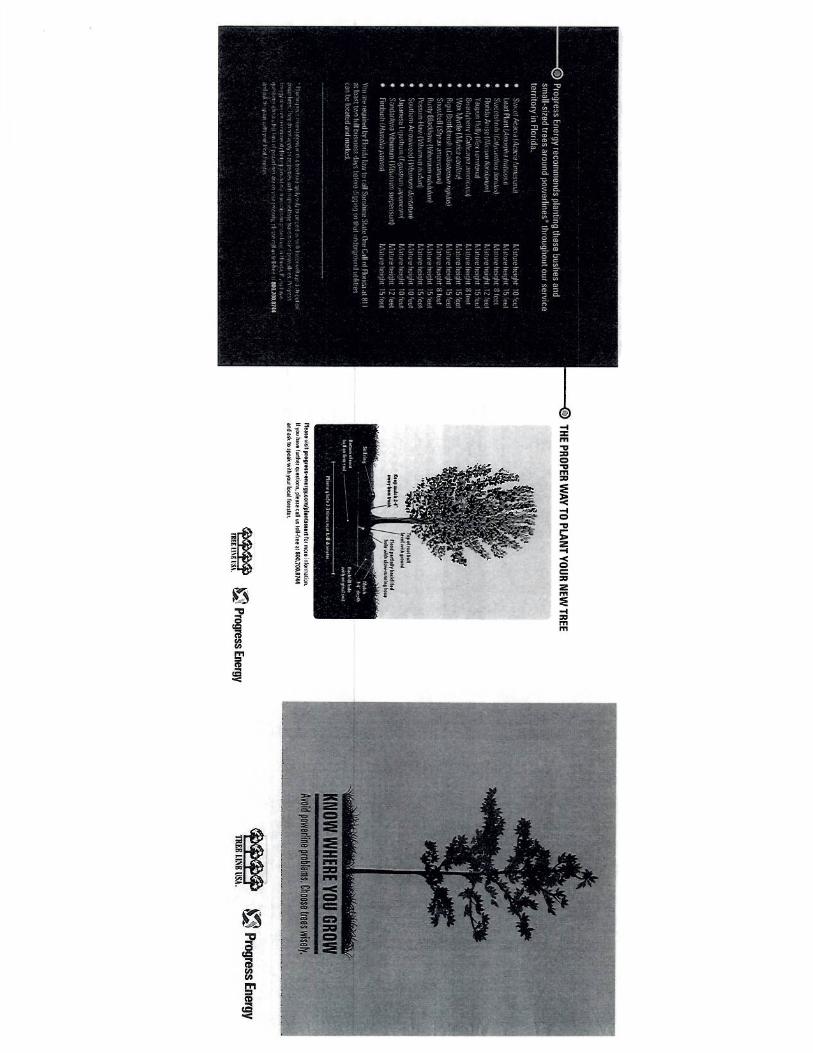
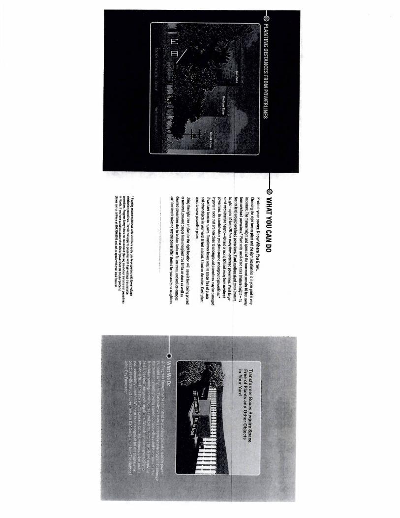


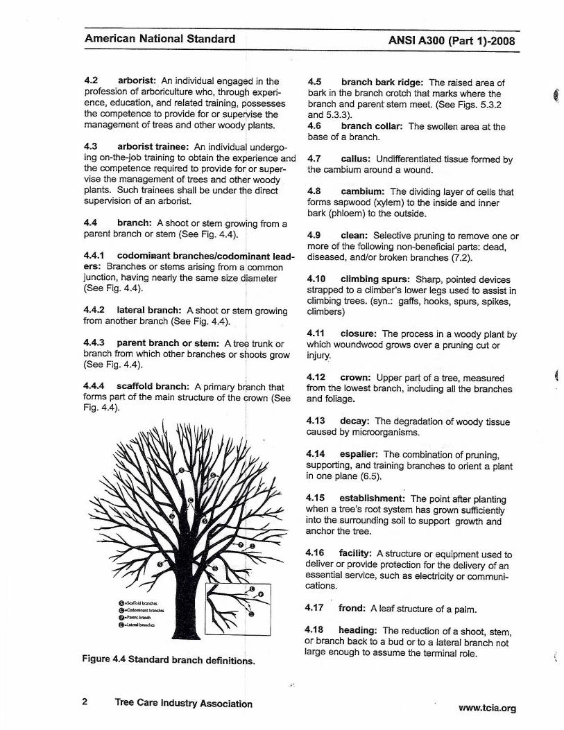
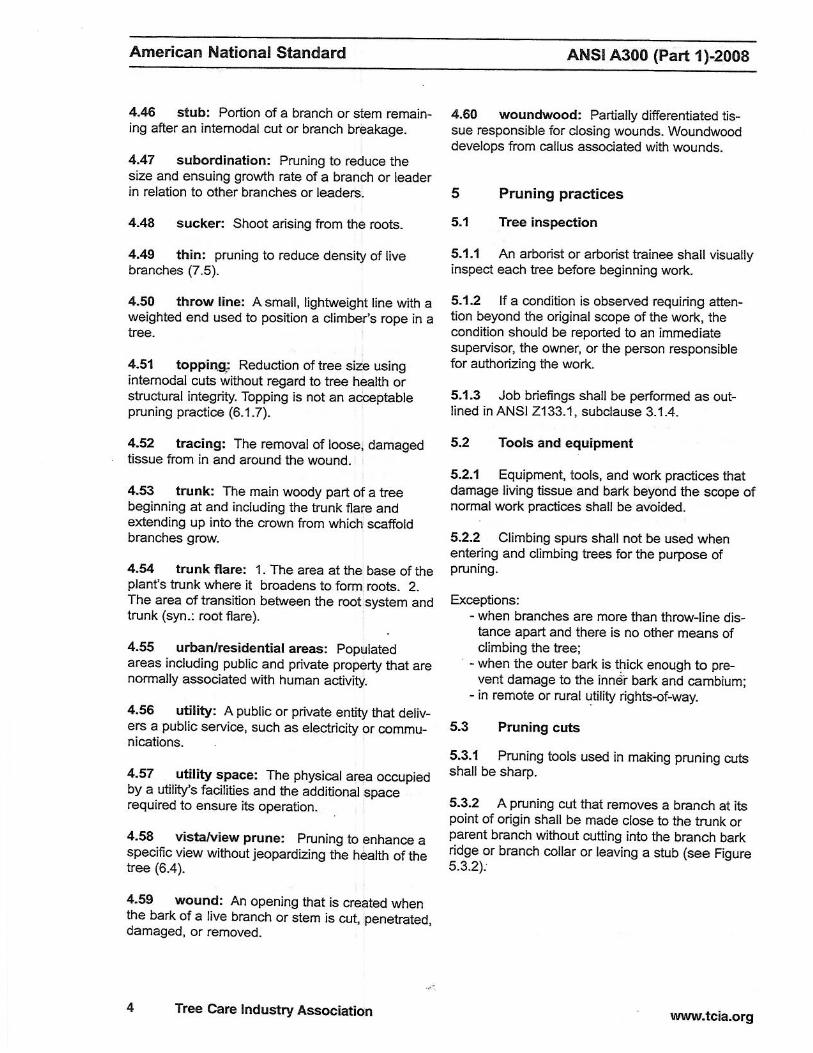
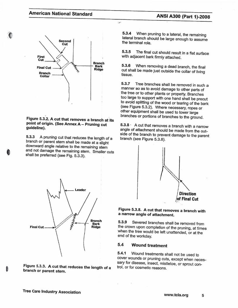

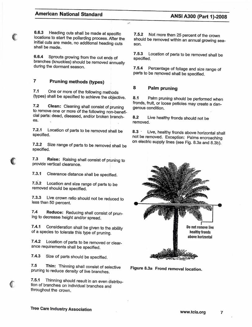
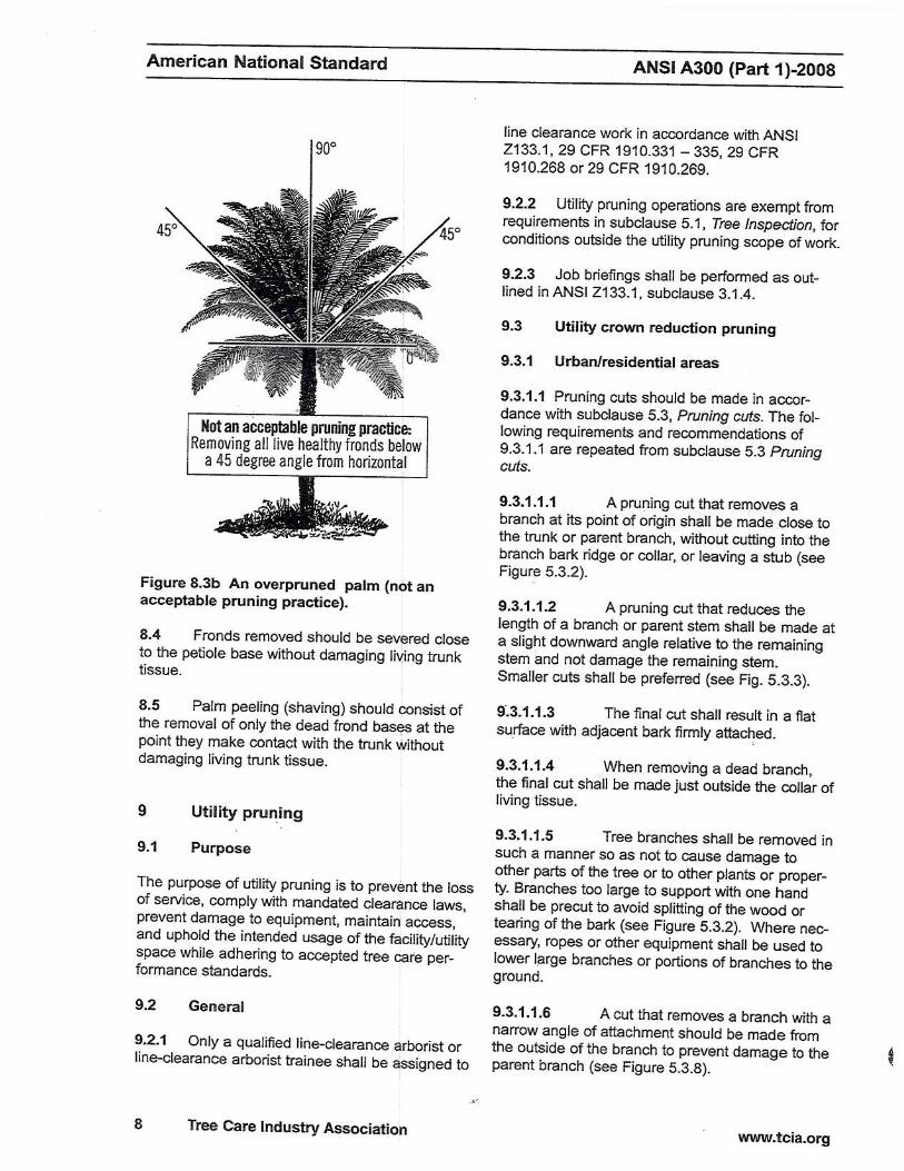
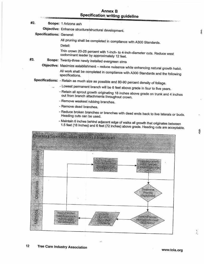

ATTACHMENT T
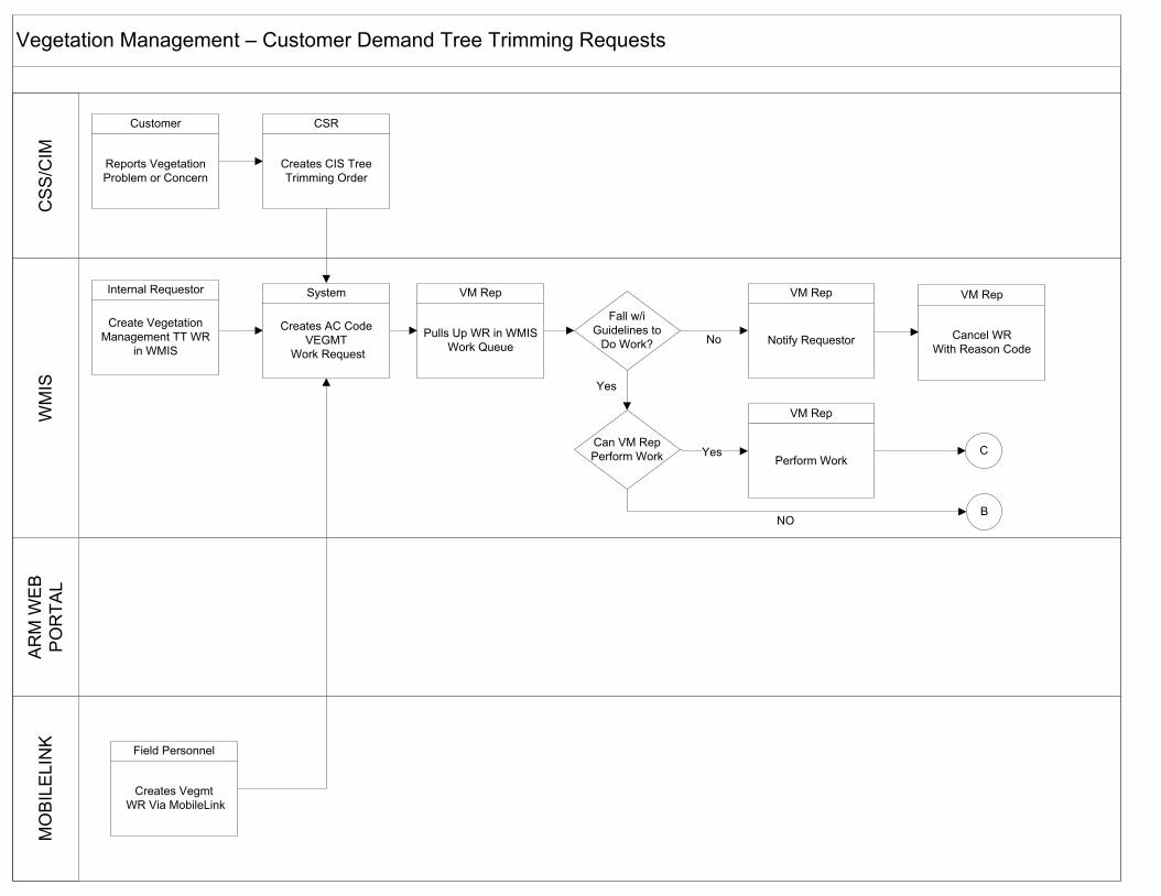
Vegetation Management – Customer Demand Tree Trimming RequestsM
OB
ILE
LIN
KA
RM
WE
B
PO
RTA
LW
MIS
CS
S/C
IM
No
Yes
BNO
Customer
Reports Vegetation Problem or Concern
CSR
Creates CIS Tree Trimming Order
Internal Requestor
Create Vegetation Management TT WR
in WMIS
System
Creates AC Code VEGMT
Work Request
Field Personnel
Creates Vegmt WR Via MobileLink
VM Rep
Pulls Up WR in WMIS Work Queue
Fall w/i Guidelines to
Do Work?
Can VM Rep Perform Work
VM Rep
Perform Work
VM Rep
Notify Requestor
VM Rep
Cancel WRWith Reason Code
Yes
C
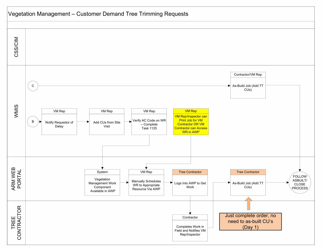
Vegetation Management – Customer Demand Tree Trimming RequestsTR
EE
C
ON
TRA
CTO
RA
RM
WE
B
PO
RTA
LW
MIS
CS
S/C
IM
B
FOLLOW ASBUILT/CLOSE
PROCESS
VM Rep
Notify Requestor of Delay
System
Vegetation Management Work
Component Available in AWP
VM RepVM Rep/Inspector can
Print Job for VM Contractor OR VM
Contractor can Access WR in AWP
VM Rep
Manually Schedules WR to Appropriate Resource Via AWP
Contractor
Completes Work in Field and Notifies VM
Rep/Inspector
Tree Contractor
As-Build Job (Add TT CUs)
C
Tree Contractor
Logs Into AWP to Get Work
Contractor/VM Rep
As-Build Job (Add TT CUs)
VM Rep
Verify AC Code on WR – Complete Task 1125
VM Rep
Add CUs from Site Visit
Just complete order, no need to as-built CU’s
(Day 1)

ATTACHMENT U
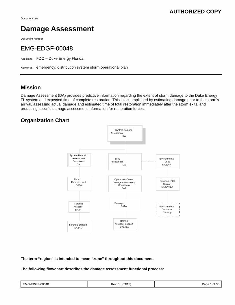
AUTHORIZED COPY
EMG-EDGF-00048 Rev. 1 (03/13) Page 1 of 30
Document title
Damage Assessment Document number
EMG-EDGF-00048 Applies to: FDO – Duke Energy Florida Keywords: emergency; distribution system storm operational plan
Mission Damage Assessment (DA) provides predictive information regarding the extent of storm damage to the Duke Energy FL system and expected time of complete restoration. This is accomplished by estimating damage prior to the storm’s arrival, assessing actual damage and estimated time of total restoration immediately after the storm exits, and producing specific damage assessment information for restoration forces.
Organization Chart
The term “region” is intended to mean “zone” throughout this document.
The following flowchart describes the damage assessment functional process:
System DamageAssessment
DA
Zone Assessment
DA
EnvironmentalLead
DA/ENV
Operations CenterDamage Assessment
CoordinatorDA2
Damage DA2A
EnvironmentalSupport
DA/ENV1A
EnvironmentalContractorCleanup
DamagAssessor Support
DA2A1A
System ForensicAssessmentCoordinator
DA
ZoneForensic Lead
DA3A
ForensicAssessor
DA3A
Forensic SupportDA3A1A
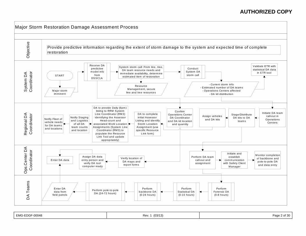
AUTHORIZED COPY
EMG-EDGF-00048 Rev. 1 (03/13) Page 2 of 30
Major Storm Restoration Damage Assessment ProcessS
yste
m D
AC
oord
inat
orO
ps.C
ente
r DA
Coo
rdin
ator
DA
Tea
ms
Reg
iona
l DA
Coo
rdin
ator
Obj
ectiv
e
Provide predictive information regarding the extent of storm damage to the system and expected time of completerestoration
START
M ajor stormim m inent
Rece ive DApredictivem odel info
fromDSSC1A
System storm ca ll: From line , tree,DA team resource needs and
im m ediate availability, dete rm ineestim ated item of restoration
ResourceM anagem ent, secure
line and tree resources
ConductSystem DAstorm call
- Current storm info- Estim ated num ber o f DA team s
- Operations Centers affected- DA kit distribu tion
Validate ETR withstatistical DA da ta
in ETR tool
Notify Fleet ofvehicle needsfor DA team sand locations
Notify S tagingand Log istics
of all DAteam countsand location
DA to com ple tein itial Assessor
Listing and identifyStorm Location
Assignm ent (usespecific Resource
Link form )
Initiate DA teamcall-out in
Opera tionsCenters
Stage/DistributeDA kits to DA
team s
Assign vehiclesand DA kits
ConfirmOperations Center
DA Coordinatorand DA kit location
and quantity
Assign DA dataentry person and
verify DA toolcom puter ready
Enter DA da taVerify location of
DA m aps andreport form s
Perform DA teamcall-out andassignm ent
In itiate andestablish
com m unicationwith Safety Client
M anager
M onitor com pletiono f backbone andpole-to-pole DAand data en try
Enter DAdata from
field patrols
Perform pole-to-poleDA (24-72 hours)
Performbackbone DA(0-24 hours)
PerformStatistical DA(0-10 hours)
PerformForensic DA(0-8 hours)
DA to provide Daily (6pm )listing to RRM System
Line Coordinator (RM 3)identifying the Assessor
Head-count andassociated W ork LocationAssignm ents (System Line
Coordinato r (RM 3) topopulate the ResourceLink Tool and update
appropriately)
AUTHORIZED COPY
EMG-EDGF-00048 Rev. 1 (03/13) Page 3 of 30
The Damage Assessment sub-processes include the following: Statistical Damage Assessment Backbone Assessment Pole to Pole Damage Assessment Tree Sweep Final Sweep
Statistical Damage Assessment This sub-process validates the resource model and ‘gauges’ the storm.
The following personnel are engaged in Statistical Damage Assessment: Damage Assessor (DA2A1) Damage Assessor Support (DA2A1A) Operations Center Damage Assessment Coordinator (DA2A) Zone Damage Assessment Coordinator (DA2) System Damage Assessment Coordinator (DA1)
The flowchart below provides a detailed view of this sub-process:
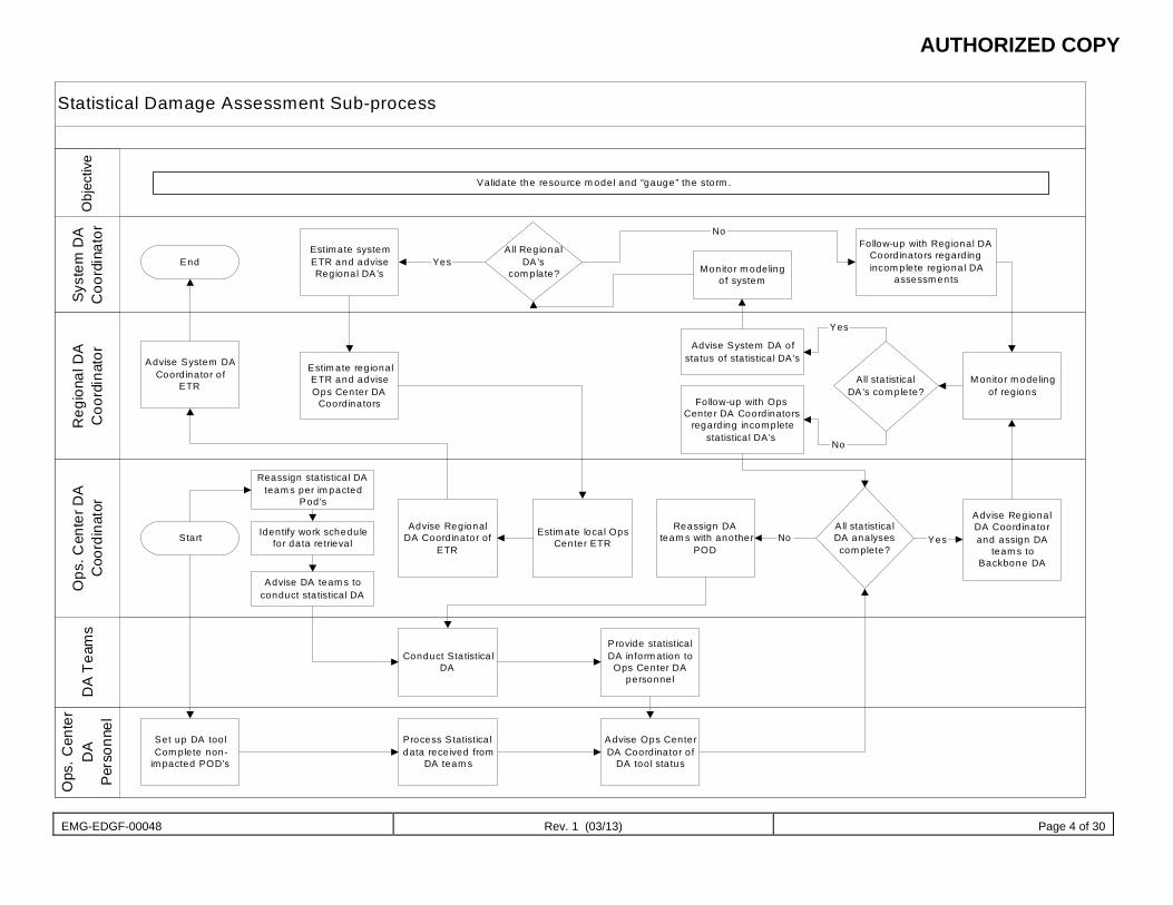
AUTHORIZED COPY
EMG-EDGF-00048 Rev. 1 (03/13) Page 4 of 30
Statistical Damage Assessment Sub-process
Ops
. Cen
ter
DA
Per
sonn
el
Syst
em D
AC
oord
inat
orR
egio
nal D
AC
oord
inat
orO
ps. C
ente
r DA
Coo
rdin
ator
DA
Tea
ms
Obj
ectiv
e
Va lidate the resource m odel and “gauge” the storm .
EndEstimate systemETR and adviseRegional DA’s
All RegionalDA’s
com plate? Monitor m odelingof system
Follow-up with Regional DACoord inators regard ingincom plete reg ional DA
assessm ents
Advise System DACoord inator o f
ETR
Estim ate reg ionalETR and adviseOps Center DA
Coord inators
Advise System DA ofstatus of sta tistica l DA’s
Follow-up with OpsCenter DA Coord inators
regard ing incompletestatistica l DA’s
All sta tisticalDA’s com plete?
M onitor m odelingof reg ions
Start
Reassign statistica l DAteam s per im pacted
Pod’s
Advise DA team s toconduct sta tistica l DA
Identify work schedulefor data re trieval
Advise RegionalDA Coord inator of
ETR
Estimate loca l OpsCenter ETR
Advise RegionalDA Coord inatorand assign DA
team s toBackbone DA
All sta tistica lDA analysescom plete?
Reassign DAteam s with another
POD
Conduct Statistica lDA
Provide statistica lDA in form ation to
Ops Center DApersonnel
Set up DA too lCom plete non-
im pacted POD’s
Process Statistica ldata received from
DA team s
Advise Ops CenterDA Coordinator o f
DA too l sta tus
No Yes
No
Yes
Yes
No

AUTHORIZED COPY
EMG-EDGF-00048 Rev. 1 (03/13) Page 5 of 30
Backbone Assessment This sub-process provides data for restoring the ‘backbone’ of the distribution systems, models TCA/OMS, and determines the number of customers who are out of service.
The following personnel are engaged in Backbone Assessment: Damage Assessor Support (DA2A1A) Damage Assessor (DA2A1) Operations Center Damage Assessment Coordinator (DA2A) Zone Damage Assessment Coordinator (DA2) System Damage Assessment Coordinator (DA1)
The flowchart below provides a detailed view of this sub-process:
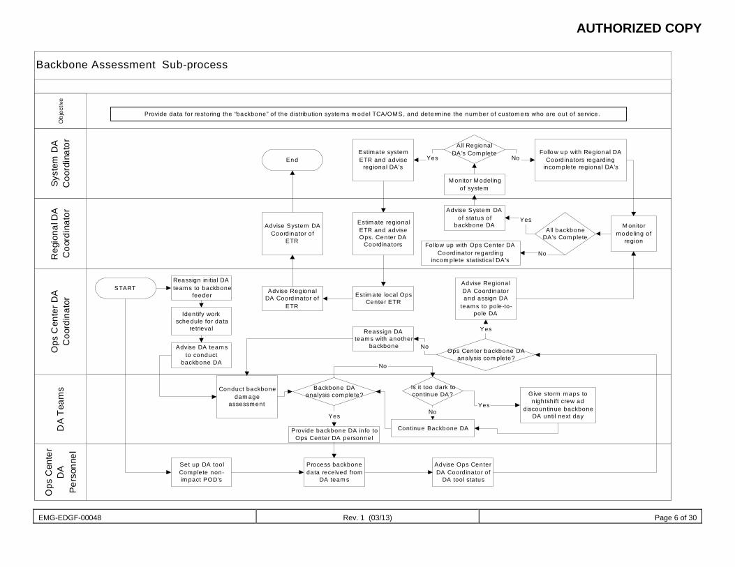
AUTHORIZED COPY
EMG-EDGF-00048 Rev. 1 (03/13) Page 6 of 30
Backbone Assessment Sub-processO
ps C
ente
rD
APe
rson
nel
Syst
em D
AC
oord
inat
orR
egio
nal D
AC
oord
inat
orO
ps C
ente
r DA
Coo
rdin
ator
DA
Team
sO
bjec
tive
EndEstimate systemETR and advise
regional DA’s
A ll RegionalDA ’s Com plete
M onitor Modelingof system
Follow up with Regional DACoordinators regarding
incom plete regional DA’s
Advise System DACoordinator of
ETR
Reassign initia l DAteams to backbone
feederSTART
Advise DA teamsto conduct
backbone DA
Identify workschedule for data
retrieval
Advise RegionalDA Coord inator of
ETR
Estimate regionalETR and adviseOps. Center DA
Coordinators
Estim ate local OpsCenter ETR
Reassign DAteams with another
backbone
Advise System DAof status of
backbone DA
Follow up with Ops Center DACoordinator regarding
incom plete statistical DA’s
A ll backboneDA’s Complete
M onitormodeling of
region
Conduct backbonedam age
assessment
Backbone DAanalysis com plete?
Provide backbone DA info toOps Center DA personnel
Is it too dark tocontinue DA?
Continue Backbone DA
Advise RegionalDA Coordinatorand assign DA
teams to pole-to-pole DA
Ops Center backbone DAanalysis com plete?
Set up DA toolComplete non-im pact POD’s
Process backbonedata received from
DA team s
Advise Ops CenterDA Coordinator of
DA tool status
Give storm maps tonightsh ift crew ad
discountinue backboneDA until next day
Yes
Yes
No
No
Yes
No
Yes
No
NoYes
Provide data for restoring the “backbone” of the d istribution system s m odel TCA/OMS, and determ ine the number of custom ers who are out of service.
AUTHORIZED COPY
EMG-EDGF-00048 Rev. 1 (03/13) Page 7 of 30
Pole to Pole Damage Assessment This sub-process determines the location and nature of damage, develops crew work plans, models trouble call analysis (TCA) and outage management system (OMS), and develops estimated times of restoration by feeder.
The following personnel are engaged in Pole to Pole Damage Assessment: Damage Assessor Support (DA2A1A) Damage Assessor (DA2A1) Operations Center Damage Assessment Coordinator (DA2A) Zone Damage Assessment Coordinator (DA2) System Damage Assessment Coordinator (DA1) Environmental Lead (DA/ENV1)
The flowchart below provides a detailed view of this sub-process:
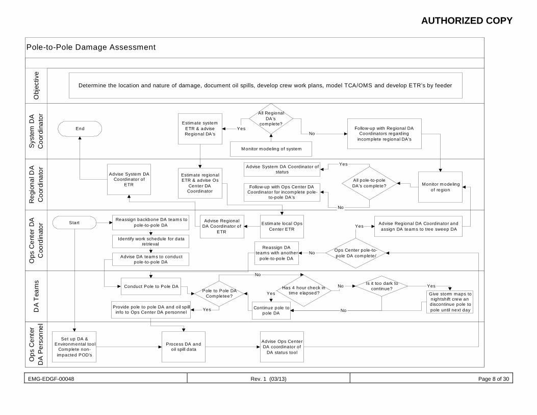
AUTHORIZED COPY
EMG-EDGF-00048 Rev. 1 (03/13) Page 8 of 30
Pole-to-Pole Damage Assessment
Ops
Cen
ter
DA
Pers
onne
lS
yste
m D
AC
oord
inat
orR
egio
nal D
AC
oord
inat
orO
ps C
ente
r DA
Coo
rdin
ator
DA
Team
sO
bjec
tive
Determine the location and nature of damage, document oil spills, develop crew work plans, model TCA/OMS and develop ETR’s by feeder
EndEstimate system
ETR & adviseRegional DA’s
All RegionalDA’s
complete?
Monitor modeling of system
Follow-up with Regional DACoordinators regarding
incomplete regional DA’s
Monitor modelingof region
All pole-to-poleDA’s complete?
Advise System DA Coordinator ofstatus
Follow-up with Ops Center DACoordinator for incomplete pole-
to-pole DA’s
Estimate regionalETR & advise Os
Center DACoordinator
Advise System DACoordinator of
ETR
StartReassign backbone DA teams to
pole-to-pole DA
Identify work schedule for dataretrieval
Advise DA teams to conductpole-to-pole DA
Advise RegionalDA Coordinator of
ETR
Estimate local OpsCenter ETR
Advise Regional DA Coordinator andassign DA teams to tree sweep DA
Ops Center pole-to-pole DA complete/
Reassign DAteams with another
pole-to-pole DA
Conduct Pole to Pole DA
Provide pole to pole DA and oil spillinfo to Ops Center DA personnel
Pole to Pole DACompletee?
Has 4 hour check intime elapsed?
Is it too dark tocontinue?
Continue pole topole DA
Give storm maps tonightshift crew andiscontinue pole topole until next day
Set up DA &Environmental tool
Complete non-impacted POD’s
Process DA andoil spill data
Advise Ops CenterDA coordinator of
DA status tool
Yes
No
Yes
No Yes
No
Yes
Yes
No
No
YesNo
AUTHORIZED COPY
EMG-EDGF-00048 Rev. 1 (03/13) Page 9 of 30
Tree Sweep This sub-process mitigates post-storm, tree-caused outages by removing damaged limbs and trees that have not caused an outage during the event but have the potential to do so afterwards.
The following personnel are engaged in Tree Sweep: Business Operations Foresters Inspector System Damage Assessment Coordinator (DA1)
The flowcharts below provide a detailed view of this sub-process:
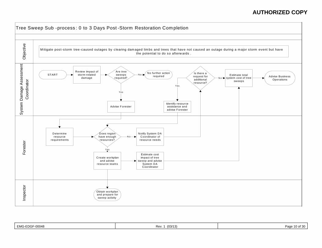
AUTHORIZED COPY
EMG-EDGF-00048 Rev. 1 (03/13) Page 10 of 30
Tree Sweep Sub -process : 0 to 3 Days Post -Storm Restoration Com pletionS
yste
m D
amag
e A
sses
smen
t C
oord
inat
orFo
rest
erIn
spec
tor
Obj
ectiv
e
M it igate pos t-s torm tree -caused outages by c learing dam aged lim bs and trees that have not caused an outage during a m ajor s torm event but have the potential to do so afterw ards .
STARTReview impact of
storm-related damage
Are tree sweeps
required?
No further action requiredN o
Advise Forester
Yes
Determine resource
requirements
Does region have enough resources?
Notify System DA Coordinator of
resource needs
Create workplan and advise
resource teams
Obtain workplan and prepare for sweep activity
Yes
N o
Estimate cost impact of tree
sweep and advise System DA Coordinator
Is there a request for additional resource?
Estimate total system cost of tree
sweepsN o
Identify resource assistance and advise Forester
Yes
Advise Business Operations
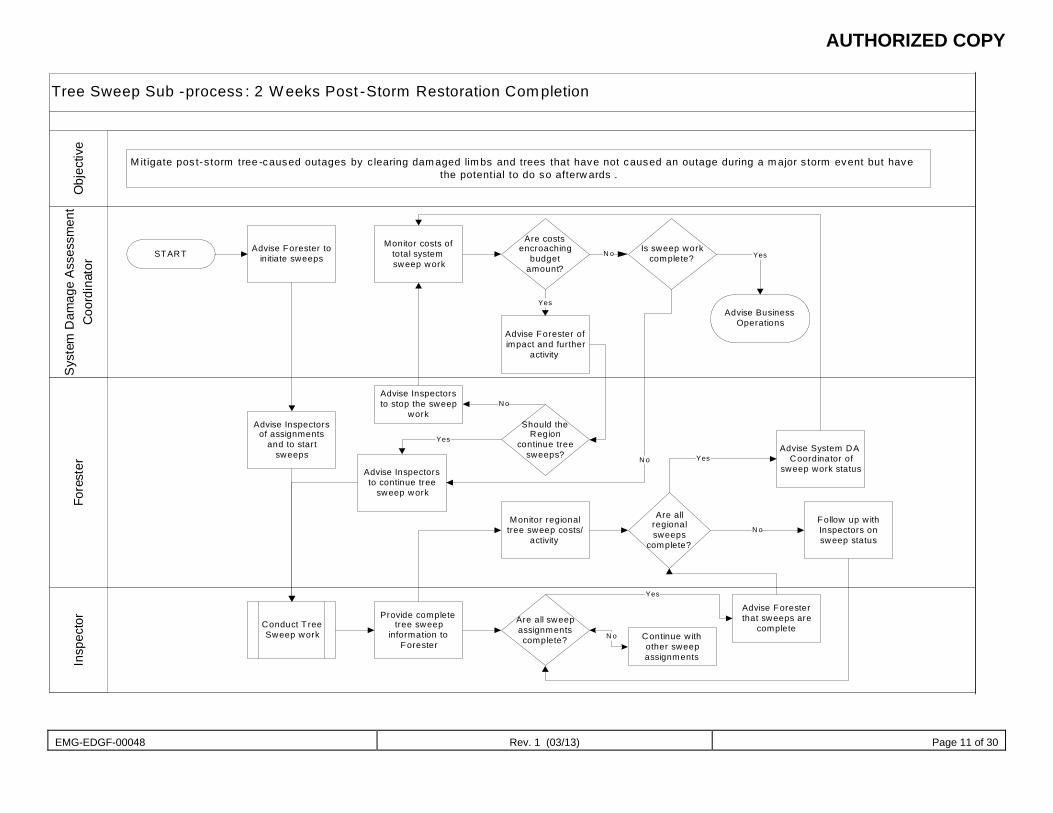
AUTHORIZED COPY
EMG-EDGF-00048 Rev. 1 (03/13) Page 11 of 30
Tree Sweep Sub -process : 2 W eeks Post -Storm Restoration Com pletionS
yste
m D
amag
e A
sses
smen
t C
oord
inat
orFo
rest
erIn
spec
tor
Obj
ectiv
e
M it igate pos t-s torm tree -caused outages by c learing dam aged lim bs and trees that have not caused an outage during a m ajor s torm event but have the potential to do so afterw ards .
START Advise Forester to initiate sweeps
Monitor costs of total system sweep work
Are costs encroaching
budget amount?
Is sweep work complete?
Advise Business Operations
Yes
Advise Forester of impact and further
activity
Yes
N o
Advise Inspectors of assignments
and to start sweeps
Conduct T ree Sweep work
Provide complete tree sweep
information to Forester
Advise Inspectors to continue tree
sweep work
Should the Region
continue tree sweeps?
N o
Yes
Monitor regional tree sweep costs/
activity
Are all sweep assignments complete? Continue with
other sweep assignments
Advise Forester that sweeps are
completeN o
Yes
Are all regional sweeps
complete?
Advise System DA Coordinator of
sweep work status
Follow up w ith Inspectors on sweep status
N o
Yes
Advise Inspectors to stop the sweep
work
N o

AUTHORIZED COPY
EMG-EDGF-00048 Rev. 1 (03/13) Page 12 of 30
Final Sweep This sub-process provides information regarding the current configuration of the distribution system (i.e., the state of each switch, existing phasing, etc.). Final Sweep teams identify existing distribution devices in need of repair or replacement due to storm damage or restoration actions immediately following the storm. Additionally, the teams record and report final sweep damage assessment information, which is used to assist in identifying the resources needed to return the distribution system to normal configuration.
The following personnel are engaged in Final Sweep: Damage Assessor Support (DA2A1A) Damage Assessor (DA2A1) Operations Center Damage Assessment Coordinator (DA2A) Zone Damage Assessment Coordinator (DA2) System Damage Assessment Coordinator (DA1) Environmental Lead (DA/ENV1)
The flowchart below provides a detailed view of this sub-process:
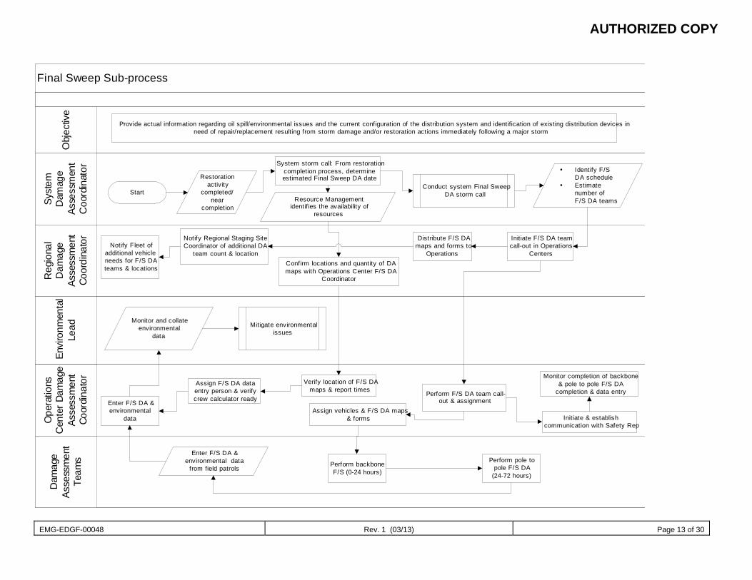
AUTHORIZED COPY
EMG-EDGF-00048 Rev. 1 (03/13) Page 13 of 30
Final Sweep Sub-process
Env
ironm
enta
lLe
ad
Syst
emD
amag
eAs
sess
men
tC
oord
inat
or
Reg
iona
lD
amag
eAs
sess
men
tCo
ordi
nato
r
Ope
ratio
nsC
ente
r Dam
age
Asse
ssm
ent
Coor
dina
tor
Dam
age
Asse
ssm
ent
Team
sO
bjec
tive
Provide actual information regarding oil spill/environmental issues and the current configuration of the distribution system and identification of existing distribution devices inneed of repair/replacement resulting from storm damage and/or restoration actions immediately following a major storm
Start
Restorationactivity
completed/near
completion
System storm call: From restorationcompletion process, determineestimated Final Sweep DA date
Resource Managementidentifies the availability of
resources
Conduct system Final SweepDA storm call
Identify F/SDA schedule
Estimatenumber ofF/S DA teams
Initiate F/S DA teamcall-out in Operations
Centers
Distribute F/S DAmaps and forms to
OperationsConfirm locations and quantity of DAmaps with Operations Center F/S DA
Coordinator
Notify Regional Staging SiteCoordinator of additional DA
team count & locationNotify Fleet of
additional vehicleneeds for F/S DAteams & locations
Verify location of F/S DAmaps & report times
Assign F/S DA dataentry person & verifycrew calculator readyEnter F/S DA &
environmentaldata
Assign vehicles & F/S DA maps& forms
Perform F/S DA team call-out & assignment
Monitor completion of backbone& pole to pole F/S DA
completion & data entry
Initiate & establishcommunication with Safety Rep
Perform backboneF/S (0-24 hours)
Enter F/S DA &environmental data
from field patrolsPerform pole to
pole F/S DA(24-72 hours)
Monitor and collateenvironmental
data
Mitigate environmentalissues
AUTHORIZED COPY
EMG-EDGF-00048 Rev. 1 (03/13) Page 14 of 30
Forensic Assessment This sub-process is not directly related to the restoration effort. The purpose of forensic assessment is to provide data on causal modes for distribution pole and structure damage due to storm related damage. The following personnel are engaged in Final Sweep:
System Damage Assessment Manager (DA1)
System Forensic Coordinator (DA3)
Zone Forensic Lead (DA3A)
Forensic Assessor(DA3A1)
The flowchart below provides a detailed view of this sub-process:
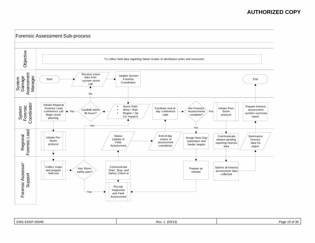
AUTHORIZED COPY
EMG-EDGF-00048 Rev. 1 (03/13) Page 15 of 30
Forensic Assessment Sub-process
Syst
emD
amag
eAs
sess
men
tM
anag
er
Syst
emFo
rens
icC
oord
inat
or
Reg
iona
lFo
rens
ic L
ead
Fore
nsic
Ass
esso
r/Su
ppor
tO
bjec
tive
To collect field data regarding failure modes of distribution poles and structures
Start
Receive stormdata from
system stormcall
Update SystemForensic
Coordinator
Initiate RegionalForensic Leadconference call
Begin stormplanning
Has Stormsafely past?
No
Collect mapsand prepare
field kits
Yes
Facilitate end-of-day conference
calls
CommunicateStart, Stop, andSafety Check-in
StatusUpdate of
FieldAssessment
Are ForensicAssessments
complete?
End-of-daystatus of
assessmentcompletion
End
Storm Path Wind / Rain Region / Op
Ctr Impacts
Landfall within48 hours?
No
Yes
Initiate Pre-Storm
protocol
Pre-tripinspectionand Field
Assessment
Initiate Post-Storm
protocolYes
Communicaterelease pendingreporting forensic
data
Assign Next Daysubstation andfeeder targets
No
Prepare asneeded
Submit all forensicassessment data
collected
Summarizeforensicdata forregion
Prepare forensicassessment
system summaryreport
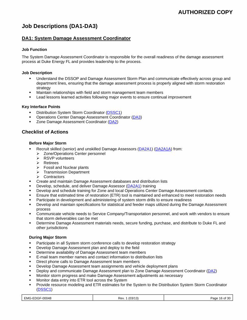
AUTHORIZED COPY
EMG-EDGF-00048 Rev. 1 (03/13) Page 16 of 30
Job Descriptions (DA1-DA3)
DA1: System Damage Assessment Coordinator
Job Function
The System Damage Assessment Coordinator is responsible for the overall readiness of the damage assessment process at Duke Energy FL and provides leadership to the process.
Job Description Understand the DSSOP and Damage Assessment Storm Plan and communicate effectively across group and
department lines, ensuring that the damage assessment process is properly aligned with storm restoration strategy
Maintain relationships with field and storm management team members Lead lessons learned activities following major events to ensure continual improvement
Key Interface Points Distribution System Storm Coordinator (DSSC1) Operations Center Damage Assessment Coordinator (DA3) Zone Damage Assessment Coordinator (DA2)
Checklist of Actions
Before Major Storm Recruit skilled (senior) and unskilled Damage Assessors (DA2A1) (DA2A1A) from:
Zone/Operations Center personnel RSVP volunteers Retirees Fossil and Nuclear plants Transmission Department Contractors
Create and maintain Damage Assessment databases and distribution lists Develop, schedule, and deliver Damage Assessor (DA2A1) training Develop and schedule training for Zone and local Operations Center Damage Assessment contacts Ensure that estimated time of restoration (ETR) tool is maintained and enhanced to meet restoration needs Participate in development and administering of system storm drills to ensure readiness Develop and maintain specifications for statistical and feeder maps utilized during the Damage Assessment
process Communicate vehicle needs to Service Company/Transportation personnel, and work with vendors to ensure
that storm deliverables can be met Determine Damage Assessment materials needs, secure funding, purchase, and distribute to Duke FL and
other jurisdictions
During Major Storm Participate in all System storm conference calls to develop restoration strategy Develop Damage Assessment plan and deploy to the field Determine availability of Damage Assessment team members E-mail team member names and contact information to distribution lists Direct phone calls to Damage Assessment team members Develop Damage Assessment team assignments and vehicle deployment plans Deploy and communicate Damage Assessment plan to Zone Damage Assessment Coordinator (DA2) Monitor storm progress and make Damage Assessment adjustments as necessary Monitor data entry into ETR tool across the System Provide resource modeling and ETR estimates for the System to the Distribution System Storm Coordinator
(DSSC1)
AUTHORIZED COPY
EMG-EDGF-00048 Rev. 1 (03/13) Page 17 of 30
After Major Storm Demobilize deployed Damage Assessment teams Process billing and invoices for retirees and contractors Lead lessons learned activities Provide input into DSSOP improvement Refurbish Damage Assessment kit materials
Training Requirements
Before Major Storm Review DSSOP and recent lessons learned to ensure understanding of “the big picture” as it pertains to
damage assessment, restoration, and customer communications Participate in developing storm drill scenarios to ensure readiness of all those involved in the damage
assessment process Communicate with Human Resources to obtain lists of recent retirees for recruiting purposes Review and test tools to ensure workability and competency of users: Resource Tracking, Damage
Assessment Data Entry, Damage Assessment ETR (Web-based) Review Damage Assessment training module for potential enhancements Develop and implement Damage Assessment training classes for newly recruited Damage Assessors (DA2A1)
and contractors Communicate with Damage Assessors (DA2A1) to enlist support for upcoming storm season
Event Promotion Success Factors Coordination with corporate storm team to ensure awareness of the damage assessment process and
requirements Coordination and linkage with Zone Damage Assessment Coordinators (DA2) and Operations Center Damage
Assessment Coordinators (DA2A) to ensure an overall understanding of the damage assessment process, and to make sure that needed maps are in place, Damage Assessment Data Entry and ETR tools are functional, and Damage Assessment resource-sharing capability is available
Awareness of storm conference call schedule (all processes) Coordination with Transmission Department storm team for potential helicopter resources
Engaged in the Following Sub-processes Predictive Modeling Statistical Damage Assessment Pole to Pole Damage Assessment Backbone Assessment Tree Sweep Final Sweep Estimated Time of Restoration Management Forensic Assessment
AUTHORIZED COPY
EMG-EDGF-00048 Rev. 1 (03/13) Page 18 of 30
DA2: Zone Damage Assessment Coordinator
Job Function
The Zone Damage Assessment Coordinator is responsible for the overall readiness of the damage assessment process within the assigned Zone and provides leadership to the process.
Job Description Understand the Damage Assessment Storm Plan and communicate effectively across the Zone to ensure that
the damage assessment process is in a ready state Communicate with the System Damage Assessment Coordinator (DA1) to ensure linkage with the DSSOP Participate in lessons learned activities following major events to ensure continual improvement
Key Interface Points Operations Center Damage Assessment Coordinators (DA2A) Zone Storm Coordinator (REG2) System Damage Assessment Coordinator (DA1)
Checklist of Actions
Before Major Storm Organize and participate in training of Operations Center Damage Assessment personnel Stay linked with System Damage Assessment Coordinator (DA1) to ensure readiness Ensure that all Operations Center contacts have the current ETR tool and are trained in its use Ensure that all Damage Assessment kits in Operations Centers are current Ensure that Zone GIS Coordinators provide resources for timely printing of feeder maps and statistical
maps for damage assessment Work with Zone management (REG1 and REG2) to ensure resource-sharing capability in the event the
Zone is not impacted by a storm (i.e., how many Damage Assessment teams can be made available elsewhere)
During Major Storm Participate in Zone storm conference calls Communicate with System Damage Assessment Coordinator (DA1) to ensure that the deployment plan is
understood Monitor storm progress and make Damage Assessment adjustments as necessary Monitor ETR tool for data input Duke and maintain communications with Operations Center Damage
Assessment contacts to ensure that data flow is timely Provide Zone resource modeling from statistical damage assessment data If Zone is not impacted by storm, engage Zone Damage Assessment Coordinator (DA2) to develop a
Damage Assessment resource-sharing plan for use elsewhere in the System
After Major Storm Participate in demobilizing efforts once restoration is complete Participate in lessons learned activities Provide support to System Damage Assessment Coordinator (DA1) to determine refurbishing materials for
Damage Assessment kits Ensure that Operations Center feeder maps and statistical sampling maps get restocked for next storm
AUTHORIZED COPY
EMG-EDGF-00048 Rev. 1 (03/13) Page 19 of 30
Training Requirements
Before Major Storm
Review Zone Storm Plan and recent lessons learned to ensure understanding of “the big picture” as it pertains to damage assessment, restoration, and customer communications
Review and test tools to ensure workability and competency of users: Resource Tracking, Damage Assessment Data Entry, and Damage Assessment ETR (Web-based)
Provide the DA training/safety awareness presentation at the DA staging sites prior to dispatching DA teams
Event Promotion Success Factors Coordination with Zone storm team to ensure awareness of the damage assessment process, requirements,
and resource-sharing capability in the event the Zone is not impacted by a major storm (i.e., how many Damage Assessment teams can be supplied to the DSSC)
Coordination and linkage with System Damage Assessment Coordinator (DA1) and Operations Center Damage Assessment Coordinators (DA2A) to ensure overall understanding of damage assessment process and readiness (maps in place, Damage Assessment Data Entry and ETR tools functional, etc.)
Awareness of Zone storm conference call schedule Promoting safety!!!
Engaged in the Following Sub-processes Pole Forensic Damage Assessment Statistical Damage Assessment Backbone Assessment Pole to Pole Damage Assessment Final Sweep
DA2A: Operations Center Damage Assessment Coordinator
Job Function
The Operations Center Damage Assessment Coordinator is responsible for the overall readiness of the damage assessment process within the assigned Operations Center.
Job Description Understand the Damage Assessment Storm Plan and communicate effectively within the Operations Center to
ensure that the damage assessment process is in a ready state Communicate with Zone Damage Assessment Coordinator (DA2) to ensure linkage with the DSSOP Participate in lessons learned activities following major events to ensure continual improvement
Key Interface Points Operations Center storm team Zone Damage Assessment Coordinator (DA2) System Damage Assessment Coordinator (DA1)
Checklist of Actions
Before Major Storm Participate in training of Operations Center Damage Assessment personnel Stay linked with Zone Damage Assessment Coordinator (DA2) to ensure readiness Ensure that the most current version of the ETR tool is on appropriate Operations Center computers and
that designated personnel are trained in its use Maintain Damage Assessment kits in the Operations Center and provide local maps as needed Ensure that adequate feeder and statistical maps are available for Damage Assessment use Provide directions and addresses to beginning points of all statistical sampling maps
AUTHORIZED COPY
EMG-EDGF-00048 Rev. 1 (03/13) Page 20 of 30
During Major Storm Communicate with Zone Damage Assessment Coordinator (DA2) to ensure that deployment plan is
understood Develop logistics and deploy Damage Assessment plan for the Operations Center Work with Damage Assessor (DA2A1) to provide refresher training to incoming teams Input statistical data into ETR tool, perform resource modeling for the Operations Center, and upload data
to server Input non-emergency environmental reports into environmental tool for tracking by the Zone
Environmental Lead (DA/ENV1) Input actual damage data into ETR tool to assist in developing feeder-level ETRs Provide feeder-level ETRs to Zone Damage Assessment Coordinator (DA2) for review prior to data
loading in Outage Management System (OMS) Ensure that Damage Assessment data and maps are provided to Feeder/Field Coordinators (OPS2C1A) Fax completed Actual Damage Assessment forms to Distribution Control Center (DCC) (fax # is on bottom
of form) for creation of outages in Trouble Call Analysis (TCA) Ensure a smooth transition for Damage Assessment teams—from performing damage assessment to
leading crews, running Outage Tickets, etc. If Operations Center is not directly impacted by the storm, offer local resources to Zone Damage
Assessment Coordinator (DA2) for developing a resource-sharing plan
After Major Storm Participate in demobilization efforts once restoration is complete DA teams are released to the Zone
Damage Assessment Coordinator (DA2) Participate in lessons learned activities Survey Damage Assessment kits and provide list of needs to Zone Damage Assessment Coordinator
(DA2) Restock Operations Center feeder maps, statistical sampling maps, and local maps as needed
Training Requirements
Before Major Storm Review Operations Center Storm Plan and recent lessons learned to ensure understanding of “the big
picture” as it pertains to restoration and customer communications Review and test tools to ensure workability and competency of users: Resource Tracking, Damage
Assessment Data Entry, and Damage Assessment ETR (Web-based) Ensure the DA training/safety awareness presentation was conducted with all DA teams at the DA staging
sites prior to dispatching DA teams
Event Promotion Success Factors Coordination with Operations Center Resource Management Coordinator (OPS3) to ensure awareness of the
damage assessment process and requirements Coordination and linkage with System Damage Assessment Coordinator (DA1) and Zone Damage
Assessment Coordinator (DA2) to ensure overall readiness Ensuring that the following items are available: Damage Assessment statistical maps, multiple copies (five
recommended) of feeder maps, Damage Assessment kits, and local maps
Engaged in the Following Sub-processes Statistical Damage Assessment Backbone Assessment Pole to Pole Damage Assessment Final Sweep Estimated Time of Restoration Management
AUTHORIZED COPY
EMG-EDGF-00048 Rev. 1 (03/13) Page 21 of 30
DA2A1: Damage Assessor
Job Function The Damage Assessor performs field damage assessments.
Job Description Understand the Damage Assessment Storm Plan and communicate effectively across the Zone to ensure that
the damage assessment process is in a ready state Oversee Damage Assessment teams, making sure that they are properly prepared, equipped, and housed Conduct refresher and safety trainings with Damage Assessment teams Track Duke of damage assessment work and move resources as needed Communicate with the System Damage Assessment Coordinator (DA1) to ensure linkage with the DSSOP
Key Interface Points Feeder/Field Coordinators (OPS2C1A) Operations Center Damage Assessment Coordinators (DA2A) System Damage Assessment Coordinator (DA1)
Checklist of Actions
Before Major Storm Attend Damage Assessment briefing to get assignment, team information, and up-to-date weather update Attend pre-storm season training to ensure familiarity with: Damage assessment process, forms, etc. ETR tool review Maps to Operations Centers and staging sites
During Major Storm
Before traveling to location: Access Storm Center Website (“Current Information”) and print Damage Assessment assignment
document. Download current Distribution Information System (DIS) Field View data for assigned area (optional) Notify assigned Operations Center of schedule, estimated time of arrival of teams, and preparations
needed prior to arrival (vehicle assignment, etc.) Determine whether the Operations Center has resource needs (Network routers, office supplies, hardhats,
etc.)
Before storm, after arriving at assigned location: Review skill level of assigned Damage Assessment team members Access Storm Center Website (“Current Information”), and print copy of most current Damage
Assessment assignment document and other information, and provide to Damage Assessment tea members
Ensure that Damage Assessment vehicles are in place and obtain keys Record vehicle and tag information for each assigned vehicle Remind Damage Assessment team members to return vehicles to point of origin
Provide “just in time” Damage Assessment refresher training to all Damage Assessment teams immediately prior to major storm event. Suggested meeting format:
Briefly cover “Damage Assessment Why Do It?” and “Damage Assessment Requirements” slides
AUTHORIZED COPY
EMG-EDGF-00048 Rev. 1 (03/13) Page 22 of 30
Hand out color copies of the following slides and discuss: Damage Assessment Color Coding DIS Feeder Maps Statistical Damage Assessment Form Example Damage Assessment Scenario #1 (with damage data, no color coding) Damage Assessment Data Form Scenario #1 (completed) Damage Assessment Scenario #1 (final) Damage Assessment Scenario #2 (final) Damage Assessment Data Form Scenario #2 Damage Assessment Scenario #3 (final) Damage Assessment Data Form Scenario #3 Wrap up with reminders from the Personal Safety and Vehicle Safety slides
Ensure that all Damage Assessment teams have the following items (one per team): Damage Assessment bag
Strobe light Hand-held light (red “Show Me” light with 12v charger, fully charged) Flood light Supply of Damage Assessment forms (10 copies statistical and 25 copies pole-to-pole) Local road maps Emergency numbers Damage Assessment team member contact numbers Hand-held radios (if Operations Center has them available for Damage Assessment use) Operations Center contact numbers
(NOTE: All of these materials are located at each Operations Center and can be obtained from the local Administrative Support or Damage Assessment contact)
Coordinate with Operations Center Damage Assessment contact to: Locate statistical grid, distribution feeder, and local maps Organize statistical assessment and assign Damage Assessment teams Define the backbone for each feeder Utilize statistical assessment data and TCA data to determine when/if backbone assessments will
begin and where Organize runners (where needed) and meeting times with Damage Assessment teams Assign vehicles to Damage Assessment teams Ensure that extra Damage Assessment forms are available Review faxing procedure for backbone and pole-to-pole Damage Assessment forms to Customer
Service Center Ensure that backbone and pole-to-pole data are entered into ETR tool by Operations Center staff
After Major Storm Before beginning damage assessment:
Access Storm Center Website (“Current Information”), print copy of most current Damage Assessment assignment document and current weather forecast, and provide to team members
Conduct pre-job safety briefing, sharing field conditions and safety pointers Continue to emphasize working safely in hazardous situations Obtain information about housing and food arrangements and ensure that Damage Assessment teams are
in the loop Ensure pre-trip inspections are performed on vehicle
During damage assessment and restoration phase: Lead pre-job briefings prior to each assessment Track Duke of work and move resources as needed Record non-emergency oil spills and environmental issues Emergency oil spills shall be immediately reported to the Zone Environmental Lead (DA/ENV1) Ensure that color-coded feeder maps are given to Feeder/Field Coordinators (OPS2C1A) Ensure that backbone and pole-to-pole data are entered into ETR tool
AUTHORIZED COPY
EMG-EDGF-00048 Rev. 1 (03/13) Page 23 of 30
After completion of restoration work: Document:
Follow-up work for crews Transformers and poles left in field Oil spills requiring clean-up
Ensure that Damage Assessment teams return all Damage Assessment kits, lights, rental vehicles and keys, and associated items to the Operations Center when released
If Damage Assessment teams are relocated to other Operations Centers, where the total number of Damage Assessment teams deployed exceeds the set number for the Operations Center, ensure that teams carry Damage Assessment kits with them
Ensure that Damage Assessment kits are returned to the Operations Center of origin
Training Requirements Review Damage Assessment training materials Arrange to attend a Damage Assessment training class if not trained or if not deployed as a Damage Assessor
in the last three years Communicate any changes in contact numbers (home, work, cell phone, e-mail address, etc.) to System
Damage Assessment Coordinator (DA1) Keep abreast of major weather developments and proactively contact System Damage Assessment
Coordinator (DA1) regarding availability
Engaged in the Following Sub-processes: Statistical Damage Assessment Backbone Assessment Pole to Pole Damage Assessment Final Sweep Estimated Time of Restoration Management
DA2A1A: Damage Assessor Support Job Function
This position is typically filled by personnel with no experience in distribution or transmission systems. This position will work with the Damage Assessor.
Job Description
This position is primarily responsible for:
the safe operation of the patrol vehicle
entering damage assessment data that Damage Assessor has identified
performing pre-flight inspections of vehicle
participate in pre-job briefings prior to each assessment
AUTHORIZED COPY
EMG-EDGF-00048 Rev. 1 (03/13) Page 24 of 30
DA3: System Forensic Assessment Coordinator Job Function This position is responsible for the coordination of collecting and collating forensic data of distribution pole and structure damage due to a major storm. Job Description This position will:
Monitor path of approaching storm coordinate a pre-storm conference call with Zone Forensic Leads at least 48 hours prior to expected landfall.
Facilitate and document substation and feeder assignments among Zone Forensic Leads Coordinate end-of-day conference calls with Zone Forensic Leads to determine daily Duke and communicate
system forensic assignments for the following day. Develop and deliver post-storm System Forensic Summary Report to the Damage Assessment Manager
within 2 weeks after storm restoration activity has been completed. Key Interface Points System Damage Assessment Coordinator (DA1) Zone Forensic Lead (DA3A) Checklist of Actions Before Major Storms
Validate Forensic Assessment roles have been assigned and filled for all Zones Ensure that training modules are updated annually Ensure Forensic Team is trained prior to storm season Monitor path of approaching storm and coordinate pre-storm conference call with Zone Forensic Leads at least
48 hours prior to expected landfall to document initial substation and feeder assignments. During Major Storm
Facilitate end-of-day conference calls with Zone Forensic Leads to document the status of substation and feeder assignments and coordinate next day assignments
Collect and collate all forensic data After Major Storm
Develop and deliver post-storm System Forensic Summary Report to the Damage Assessment Manager within 2 weeks after storm restoration activity has been completed.
Engaged in the following Sub-process: Forensic Assessment
AUTHORIZED COPY
EMG-EDGF-00048 Rev. 1 (03/13) Page 25 of 30
DA3A: Zone Forensic Lead Job Function This position is responsible for the execution of a forensic review of the assigned Zone and for coordinating the field activities of the Forensic Assessors and Forensic Support functions. Job Description The Zone Forensic Lead will be responsible for identifying, recruiting, and training team members to perform Forensic Assessment. In addition, this position will:
Participate in pre-storm conference call with System Forensic Coordinator at least 48 hours prior to expected landfall to determine high-priority substations for Forensic Assessment and additional calls, as needed.
Communicate team assignments and expected initial reporting time/location to Forensic Assessor and Forensic Support team members 48 hours in advance of expected landfall
Secure and assign vehicles for all Forensic Assessment teams within the Zone Determine and communicate daily substation and feeder assignments by team Establish protocols and timelines with Forensic Assessment teams within the Zone for communicating daily
start, stop, and safety check-in times and notify system Damage Assessment Manager and System Forensic Coordinator if communication is not established with teams as expected.
Participate in end-of-day conference calls with System Forensic Coordinator and other Zone Forensic Leads to determine the system-wide status of Forensic Assessment and assign assessment locations for the following day
Provide complete Zone Substation Forensic Summary Reports to System Forensic Coordinator within 1 week after storm restoration activity has been completed
Key Interface Points System Forensic Assessment Coordinator (DA3) Forensic Assessor (DA3A1) Forensic Support (DA3A1A) Checklist of Actions Before Major Storms
Ensure Zone Forensic Assessment organization has been staffed and trained During Major Storm
Pre-Storm Protocol Participate in pre-storm conference call with System Forensic Coordinator and other Zone Forensic
Leads at least 48 hours in advance of expected landfall to determine resource needs and potential Day 1 assessment locations by substation and feeder.
Communicate team assignments and expected initial reporting time/location to Forensic Assessor and Forensic Support team members 48 hours in advance of expected landfall
Secure 1 vehicle for each 2 person Forensic Assessment team expected for the Zone Provide final call to Forensic Assessor and Forensic Support team members 6 to 24 hours in advance
of expected landfall to confirm team assignment and substation feeder assignments. Establish protocols and timelines with Forensic Assessment teams within the Zone for communicating
daily start, stop, and safety check-in times and notify system Damage Assessment Manager and System Forensic Coordinator
Obtain status report from Forensic Assessment teams prior to end-of-day conference call with System
Forensic Coordinator and other Zone Forensic Leads Participate in end-of-day conference calls with System Forensic Coordinator and other Zone Forensic Leads to
determine the system-wide status of Forensic Assessment and assign assessment locations for the following day
AUTHORIZED COPY
EMG-EDGF-00048 Rev. 1 (03/13) Page 26 of 30
After Major Storm Confirm vehicles have been returned Provide complete Zone Substation Forensic Summary Reports to System Forensic Coordinator within 1 week
after storm restoration activity has been completed Engaged in the following Sub-process: Forensic Assessment
DA3A1: Forensic Assessor Job Function This position is primarily responsible for conducting a forensic review and the collection of data on the failure mode of distribution poles. Job Description The Forensic Assessor will be responsible for the resources necessary to conduct the Forensic Assessment in the field, including the direct supervision of an assigned Forensic Support team member. This position will:
Be proficient in the data collection process and procedure necessary to conduct Forensic Assessment Prepare field kit upon initial notification of assignment from Zone Forensic Lead (described below) Confirm daily Forensic Assessment assignment with Zone Forensic Lead and confirm protocols and timelines
with for communicating daily start, stop, and safety check-in times Initiate contact with assigned Forensic Support team member and provide just-in-time refresher of
expectations as required Conduct pre-trip inspection with Forensic Support prior to departing local Operation Center to ensure all
materials and resources are available and that the vehicle is in safe working order Conduct pre-job briefing before each inspection Conduct field Forensic Assessment of assigned substations and/or feeders and collect required data for each
pole identified as damaged or in need of repair Report daily observations and status update to Zone Forensic Lead as assigned Complete and submit hardcopy checklist to Zone Forensic Lead for each pole identified as damaged or in
need of repair no later than 2 days after restoration activity has been completed Key Interface Points Zone Forensic Lead (DA3A) Forensic Support (DA3A1) Checklist of Actions Before Major Storms
Be knowledgeable of the roles and responsibilities of the Forensic Assessor and Forensic Support functions, including the proper procedures for collecting data regarding the failure mode of distribution poles
Be familiar with current Distribution Construction Specifications likely to be encountered during field Forensic Assessment of overhead distribution construction
Ensure PPE is inspected and in date
AUTHORIZED COPY
EMG-EDGF-00048 Rev. 1 (03/13) Page 27 of 30
During Major Storm
Print or collect current statistical grid, distribution feeder, and local road maps that correspond to assigned substations and/or feeders
Prepare daily field kit to consist of at least: Strobe light Supply of Forensic Assessment Forms (sufficient number for assigned area) Emergency numbers Forensic Assessment team member contact numbers Local Operations Center contact numbers Water Personal items
Have ready access to additional PPE for Forensic Support team member if needed Initiate contact with assigned Forensic Support team member to confirm reporting location and time Check-out vehicle Conduct pre-job briefing with Forensic Support prior to departing local Operation Center to ensure all materials
and resources are available and are in safe working order Communicate start, stop, and safety check-in times with Zone Forensic Lead as required Facilitate safe navigation to and from Forensic Assessment locations Conduct field Forensic Assessment of all assigned substations and/or feeder locations and ensure a Forensic
Assessment form has been completed with the required data for each pole identified as damaged or in need of repair
Provide direction to and supervision of Forensic Support to facilitate efficient and safe collection of data Report daily observations and status update to Zone Forensic Lead as assigned Communicate daily assignments and meeting logistics information to assigned Forensic Support team
member After Major Storm
Return vehicle Complete and submit hardcopy checklist to Zone Forensic Lead for each pole identified as damaged or in
need of repair no later than 2 days after restoration activity has been completed Engaged in the following Sub-process: Forensic Assessment
DA3A1A: Forensic Support Job Function This position will provide field support to the Forensic Assessor in the collection of required data during Forensic Assessment in the field. Job Description This position is responsible for:
Participating in pre-job briefings Safe operation of assigned passenger vehicle Cataloguing time, location, and other required data for each pole identified as damaged or in need of repair Assisting in the preparation of summary reports for use by the Zone Forensic Lead
Key Interface Points Forensic Assessor Zone Forensic Lead
AUTHORIZED COPY
EMG-EDGF-00048 Rev. 1 (03/13) Page 28 of 30
Checklist of Actions Before Major Storms
Review storm plan assignment Ensure PPE is inspected and in date If required, pack personal needs and clothing for extended period Receive pre-storm planning communication from Zone Forensic Lead
During Major Storm Arrive at assigned area with PPE and personal items Check in with the Forensic Assessor Assist Forensic Assessor with data collection Assist Forensic Assessor with maintaining communication schedule during the shift Assist Forensic Assessor with data download at the end of each shift Assist in pre-trip inspection of vehicle Participate in pre-job briefings prior to each assessment
After Major Storm
Support Forensic Assessor as required in completing summary reports Engaged in the following Sub-process: Forensic Assessment
DA/ENV1: Environmental Lead
Job Function
The Environmental Lead is the primary contact at the Zone storm center for environmental response activities. This individual will coordinate environmental responses and address all environmental issues as part of the damage assessment and restoration processes.
Job Description Participate in Zone storm calls as necessary Ensure sufficient environmental resources are available Direct environmental resources for required response activities Interface with environmental regulatory agencies as necessary Provide updates and status of environmental response activities to appropriate Company management
Key Interface Points Zone Storm Center Transmission Storm Organization Operation Center Damage Assessment Coordinator (DA2A) Zone restoration personnel (emergency spills only)
Checklist of Actions
Before Major Storm Contact environmental emergency response contractors to provide notification of potential activation for storm
response support Review and, if needed, make arrangements for material needs for environmental response activities Arrange for additional environmental FTE support from the CAROLINA ZONE Environmental Support Group
and the PE Service Company Environmental Services Section
AUTHORIZED COPY
EMG-EDGF-00048 Rev. 1 (03/13) Page 29 of 30
During Major Storm Interface with Ops Center Damage Assessment Coordinators to identify non-emergency environmental events
requiring response (interface may be accomplished by use of electronic environmental tool) Monitor assigned Zone environmental updates from Ops Center DA Coordinators
Develop environmental response plan from this information Receive emergency environmental calls from field personnel and mitigate issues Oversee environmental response activities Interface with environmental regulatory agencies Provide internal communications/updates Coordinate environmental responses as part of DA sweeps
After Major Storm Coordinate collection and management of environmental data Ensure environmental issues are completed in a timely manner Ensure proper accounting and processing of environmental related storm costs Participate in lessons learned and process enhancement
Tools and Information Needed Damage assessment data
Internal and external communication ability
Environmental contact list
Environmental Response contractor list
Distribution and Transmission team contacts
Training Requirements Job related functions
DA/ENV1A: Environmental Support
Job Function The environmental support person will typically be in the field overseeing environmental response activities. This position will report to and follow the direction of the Environmental Lead. During periods where environmental response is not required, this position will provide, as needed, support to storm restoration activities. Job Description Direct environmental response contractors and other resources performing environmental response activities. Ensure sufficient environmental resources are available for each response need in coordination with the
Environmental Lead’s direction Interface with environmental regulatory agencies as necessary Provide updates and status of environmental response activities to Environmental Lead Direct environmental response activities during final storm sweeps
Key Interface Points Environmental Lead (DA/ENV1) Operation Center Storm Personnel Transmission Storm Personnel
AUTHORIZED COPY
EMG-EDGF-00048 Rev. 1 (03/13) Page 30 of 30
Systems For Damage Assessment Team
Damage Assessment online tool ETR online tool OMS Resource Tracking tool Environmental input tool
Supplemental Information
DEF Line Contractor Crew Sheet

ATTACHMENT V
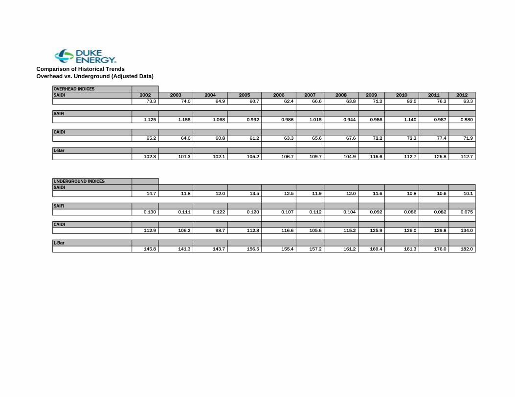
Comparison of Historical TrendsOverhead vs. Underground (Adjusted Data)
OVERHEAD INDICESSAIDI 2002 2003 2004 2005 2006 2007 2008 2009 2010 2011 2012
73.3 74.0 64.9 60.7 62.4 66.6 63.8 71.2 82.5 76.3 63.3
SAIFI1.125 1.155 1.068 0.992 0.986 1.015 0.944 0.986 1.140 0.987 0.880
CAIDI65.2 64.0 60.8 61.2 63.3 65.6 67.6 72.2 72.3 77.4 71.9
L-Bar102.3 101.3 102.1 105.2 106.7 109.7 104.9 115.6 112.7 125.8 112.7
UNDERGROUND INDICESSAIDI
14.7 11.8 12.0 13.5 12.5 11.9 12.0 11.6 10.8 10.6 10.1
SAIFI0.130 0.111 0.122 0.120 0.107 0.112 0.104 0.092 0.086 0.082 0.075
CAIDI112.9 106.2 98.7 112.8 116.6 105.6 115.2 125.9 126.0 129.8 134.0
L-Bar145.8 141.3 143.7 156.5 155.4 157.2 161.2 169.4 161.3 176.0 182.0

ATTACHMENT W
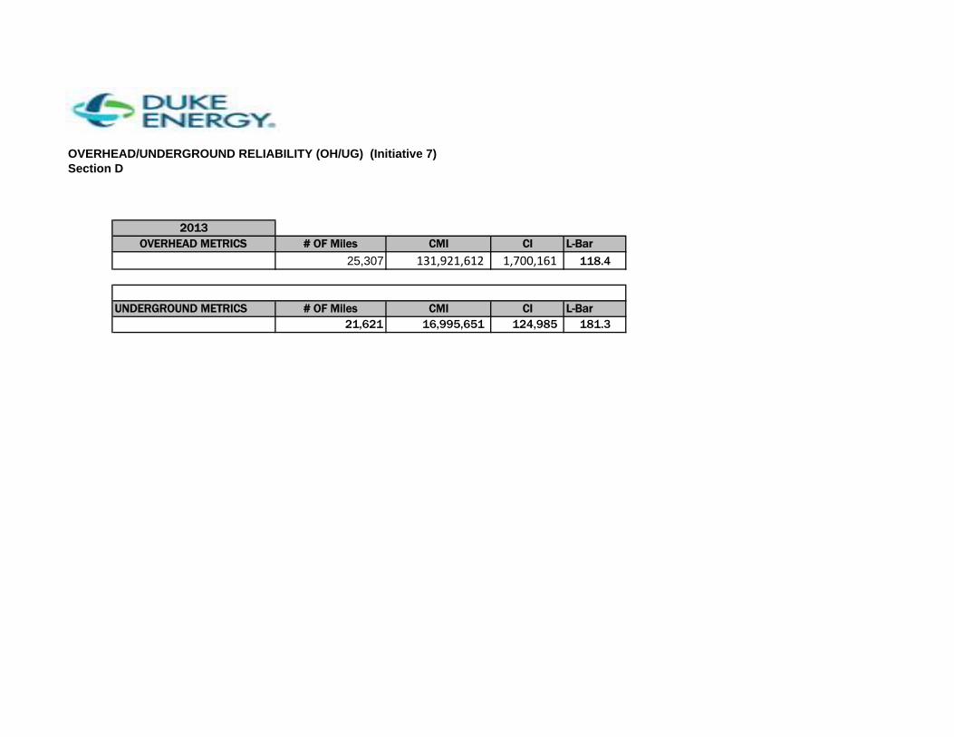
OVERHEAD/UNDERGROUND RELIABILITY (OH/UG) (Initiative 7) Section D
2013OVERHEAD METRICS # OF Miles CMI CI L-Bar
25,307 131,921,612 1,700,161 118.4
UNDERGROUND METRICS # OF Miles CMI CI L-Bar21,621 16,995,651 124,985 181.3

ATTACHMENT X
Report on Collaborative Research for Hurricane Hardening
Provided by
The Public Utility Research Center University of Florida
To the
Utility Sponsor Steering Committee
February 2014
I. Introduction The Florida Public Service Commission (FPSC) issued Order No. PSC-06-00351-PAA-EI on April 25, 2006 (Order 06-0351) directing each investor-owned electric utility (IOU) to establish a plan that increases collaborative research to further the development of storm resilient electric utility infrastructure and technologies that reduce storm restoration costs and outages to customers. This order directed IOUs to solicit participation from municipal electric utilities and rural electric cooperatives in addition to available educational and research organizations. As a means of accomplishing this task, the IOUs joined with the municipal electric utilities and rural electric cooperatives in the state (collectively referred to as the Project Sponsors) to form a Steering Committee of representatives from each utility and entered into a Memorandum of Understanding (MOU) with the University of Florida’s Public Utility Research Center (PURC). This MOU was recently extended by the Research Collaboration Partners through December 31, 2015. PURC manages the work flow and communications, develops work plans, serves as a subject matter expert, conducts research, facilitates the hiring of experts, coordinates with research vendors, advises the Project Sponsors, and provides reports for Project activities. The collaborative research has focused on undergrounding, vegetation management, hurricane-wind speeds at granular levels, and improved materials for distribution facilities. This report provides an update on the activities of the Steering Committee since the previous report dated February 2013.
II. Undergrounding The collaborative research on undergrounding has been focused on understanding the existing research on the economics and effects of hardening strategies, including undergrounding, so that informed decisions can be made about undergrounding policies and specific undergrounding projects. The collaborative has refined the computer model developed by Quanta Technologies and there has been a collective effort to learn more about the function and functionality of the computer code. PURC and the Project Sponsors have worked to fill information gaps for model inputs and significant efforts have been invested in the area of forensics data collection. Since the state has not been affected by any hurricanes since the database software was completed, there is currently no data. Therefore, future efforts to refine the undergrounding model will occur when such data becomes available. In addition, PURC has worked with doctoral and master’s candidates in the University of Florida Department of Civil and Coastal Engineering to assess some of the inter-relationships between wind speed and other environmental factors on utility equipment damage. PURC has also been contacted by engineering researchers at other universities with an interest in the model, though no additional relationships have been established. In addition to universities, PURC was contacted by researchers at the Argonne National Lab who expressed interest in modeling the effects of storm damage. The researchers ultimately chose to develop a deterministic model, but did use many of the factors that the Collaborative have attempted to quantify. Every researcher that contacts PURC cites the model as the only non-proprietary model of its kind. The research discussed in last year’s report on the relationship between wind speed and rainfall is still under review by the engineering press. Further results of this and related research can likely be used to further refine the model. III. Wind Data Collection The Project Sponsors entered into a wind monitoring agreement with WeatherFlow, Inc. Currently, WeatherFlow’s Florida wind monitoring network includes 50 permanent wind monitoring stations around the coast of Florida. The wind, temperature, and barometric pressure data being collected at these stations has been made available to the Project Sponsors. There have been no major impacts from hurricanes since the wind monitoring network was established. Once such an event does occur and wind data is captured, it is expected that forensic investigations of utilities’ infrastructure failure will be conducted and overlaid with wind observations to correlate failure modes to wind speed and turbulence characteristics. Project Sponsors and PURC will analyze such data at that time. IV. Public Outreach In last year’s report we discussed the impact of Hurricane Sandy on greater interest in storm
preparedness. PURC researchers discussed the collaborative effort in Florida with the engineering departments of the state regulators in Pennsylvania, Maryland, New York, and New Jersey. While all of the regulators and policymakers showed great interest in the genesis of the collaborative effort, and the results of that effort, they have not, at this point, shown further interest in participating in the research effort. On April 15, 2013, the Wall Street Journal published a special section entitled ‘Big Issues: Energy’ which featured authors promulgating the “Yes” or “No” position to various questions surrounding the energy industry. One of those questions was “Should Utilities Be Required to Bury Power Lines to Protect Them?”, and PURC Director of Energy Studies Ted Kury was asked to contribute the “No” position. In October, Kury and Dr. Roger Anderson of Columbia University (who had provided the “Yes” position), revisited their print debate as the keynote session of the 2013 EEI/NRECA Utility Siting Workshop in Richmond, Virginia. V. Conclusion In response to the FPSC’s Order 06-0351, IOUs, municipal electric utilities, and rural electric cooperatives joined together and retained PURC to coordinate research on electric infrastructure hardening. The steering committee has taken steps to extend the research collaboration MOU so that the industry will be in a position to focus its research efforts on undergrounding research, granular wind research and vegetation management when significant storm activity affects the state.

ATTACHMENT Y
AUTHORIZED COPY
EMG-EDGF-00042 Rev. 8 (02/14) Page 1 of 14
Document title
Distribution System Storm Operational Plan Document number
EMG-EDGF-00042 Applies to: Florida Delivery Operations and Supporting Storm Organizations – Florida Keywords: emergency; distribution system storm operational plan
Introduction At Duke Energy Florida we believe that people succeed because they act with integrity, collaborate effectively, embrace diversity, and communicate. Not only do they take responsibility for their actions and achieve objectives with speed and agility, they are intolerant of mediocrity and produce results that matter. As a company our goals are to exceed customer expectations, to deliver superior shareholder value, and to challenge employees to excel. With these goals and principles in mind, we have developed the Distribution System Storm Operational Plan (DSSOP). This plan provides a blueprint for safely restoring power to our customers in the shortest amount of time following a storm event. Designed with the flexibility to respond to both small and large storms, this comprehensive plan reflects an organizational redesign at Duke Energy Florida. The storm plan also incorporates internal feedback, suggestions and customer survey responses, documenting and applying the invaluable knowledge gained from experience. Zones, Operation Centers and supporting storm organizations are responsible for following the storm plan as identified in this document and linked storm support documents. In addition, each storm organization shall maintain an updated storm organizational chart identifying personnel in key storm roles and contact information. When applicable, this information should be inserted into the storm organizations storm folder located on the storm center web site. Operations and Zone storm centers are responsible for placing their updated storm organizational charts and contact information on their respective web sites prior to the start of hurricane season. This information should be updated, as needed, throughout the storm season.
Built on Experience At Duke Energy Florida we have faced more than our share of storms and hurricanes. In 2004, our company received the Emergency Response Award from Edison Electric Institute for “outstanding work under extreme conditions” during the unprecedented four hurricanes that pounded Florida and the Carolinas in August and September of that year. We have received this award a record five times, including our responses to hurricanes Bonnie (1998) and Floyd (1999), the January 2000 winter storm, and the December 2002 ice storm. In 2005, our company received the EEI Emergency Assistance award which recognized our storm restoration efforts in support of outside electrical utilities located in the Southeastern Electric Exchange (SEE). By applying lessons learned from past events and during the 2004 hurricane season, we were able to quickly and efficiently implement best practices, maximize manpower, and reduce damage to equipment. Lessons learned from all past storms and hurricanes have been integrated into this plan, so we may continue to produce results that matter with speed and agility before, during, and after a storm.
Plan Overview The objective of this plan is to establish a consistent approach and level of responsibility for each emergency response. This document provides the authority and coordination needed to restore electric service and maintain business continuity from emergency storm events. This plan consolidates authority to a System Level “top down” organizational structure for major storm responses and organizational structure for minor storm events.
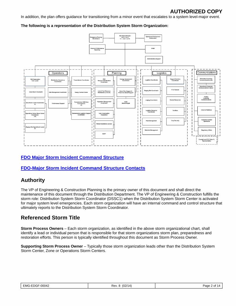
AUTHORIZED COPY
EMG-EDGF-00042 Rev. 8 (02/14) Page 2 of 14
In addition, the plan offers guidance for transitioning from a minor event that escalates to a system level-major event. The following is a representation of the Distribution System Storm Organization:
FDO Major Storm Incident Command Structure FDO-Major Storm Incident Command Structure Contacts Authority The VP of Engineering & Construction Planning is the primary owner of this document and shall direct the maintenance of this document through the Distribution Department. The VP of Engineering & Construction fulfills the storm role: Distribution System Storm Coordinator (DSSC1) when the Distribution System Storm Center is activated for major system level emergencies. Each storm organization will have an internal command and control structure that ultimately reports to the Distribution System Storm Coordinator.
Referenced Storm Title Storm Process Owners – Each storm organization, as identified in the above storm organizational chart, shall identify a lead or individual person that is responsible for that storm organizations storm plan, preparedness and restoration efforts. This person is typically identified throughout this document as Storm Process Owner. Supporting Storm Process Owner – Typically those storm organization leads other than the Distribution System Storm Center, Zone or Operations Storm Centers.
AUTHORIZED COPY
EMG-EDGF-00042 Rev. 8 (02/14) Page 3 of 14
Using the Plan The purpose of the Distribution System Storm Operational Plan (DSSOP) is to ensure that all employees are informed and aware of the roles they serve in the event of a major storm. Many of you whose jobs do not normally require involvement in service restoration will be called upon to offer your talents and services in providing logistics support, guiding crews, answering telephones at the Customer Contact Operations Center, or other critical roles. To make best use of this plan, carefully read and understand this document and the section or sections that apply to your role for your organizations storm plan listed at the back of this document. It is also helpful to read the roles and responsibilities of your interface contacts, identified and hyper-linked in your storm plan. The table of contents, listed on the end of this document provides links to individualized functional storm plans, each of which contains (or will contain in a future revision as information becomes available) a mission statement, functional process and/or sub-process descriptions, flow charts, organization charts, job descriptions, key interface points, checklists of actions, lists of needed tools and information, an inventory of systems used, and links to supplementary information. Storm role codes are provided for each job title. All Storm Process Owners will be required to certify annually that their storm organizations are prepared for a major storm event. The document below shall be completed, signed and forwarded to the Distribution System Storm Center by May 1 of each year. Storm Organization Certification Form The DSSOP has been created as a Word document and is posted on the Duke Energy Florida Intranet as a PDF file, making it easy to access, print, and keep on hand.
Testing the Plan Storm Process Owners are responsible for determining if and when testing is necessary for effective storm plan implementation, prior to the start of storm season. Preparedness and action plans to test their individual organizations can include, but are not limited to:
• Simulated emergency conditions • Drills • Communication flow reviews • Personnel and duties assignment listings review • Resource listings reviews • Evaluation of action plan readiness • Priority circuits and customer listing s review • Damage assessment plans • Relevance of forms and reports format review
The Distribution System Storm Center (DSSC) will sponsor and facilitate an annual system level storm drill to test organizational preparedness prior to the start of hurricane season. In addition, the DSSC will sponsor a lessons learned process following the drill to ensure existing storm processes are being institutionalized throughout the organization and gaps in storm planning are identified and resolved.
Updating the Plan
The Duke Energy Florida DSSOP is a dynamic document that requires periodic enhancement and regular updates to maintain its effectiveness in time-critical situations. Maintenance of the DSSOP is the responsibility of the Distribution System Storm Coordinator (DSSC1) and is accomplished in the following manner:
Updating Key Storm Personnel Telephone numbers and personnel assignments shall be updated prior to the hurricane season. In addition, updates should be made as they occur during each storm season. Zones and Operations Centers shall post their updated list of storm personnel and contact information on their respective storm web sites by May 1, with further updates required as personnel transition in and out of the organization.
AUTHORIZED COPY
EMG-EDGF-00042 Rev. 8 (02/14) Page 4 of 14
Lessons Learned Process Each Supporting Storm Process Owner will conduct a lessons learned process with their storm teams within 30 days after each major storm and have each member review and critique planning and restoration efforts. The evaluation process should include the following: • Things that went well—successes • Things that need improvement—opportunities • Lessons learned • Follow-up action plans The Storm Process Owners shall forward lessons learned and task assignments to the Distribution System Storm Coordinator who will ensure the quality of this integrated storm document. Each Operations Center Coordinator (OPS1) will send their list of recommended improvements to the Zone Storm Manager (REG1), who will compile the zone level list and forward it to the Distribution System Storm Coordinator. The Distribution System Storm Coordinator will then determine which items should be pursued to effect any system-wide changes and will develop an action plan for implementing these improvements.
Plan Maintenance Each spring prior to the start of hurricane season, the Distribution System Storm Coordinator (DSSC1) will sponsor a review of the DSSOP for any needed changes. The Distribution System Storm Coordinator Assistant (DSSC1A) will coordinate the review process with all functional processes supporting the DSSOP. Each functional process owner will be responsible for making revisions. The Distribution System Storm Coordinator (DSSC1), with the support of the Distribution System Storm Coordinator Assistant (DSSC1A), will ensure that necessary changes are incorporated. The Distribution System Storm Coordinator (DSSC1) is responsible for notifying Delivery Operations personnel of any revisions to the DSSOP and ensuring that any training needs are accomplished in a timely manner, prior to the start of the hurricane season.
The following sub-process identifies key responsibilities for updating the DSSOP:
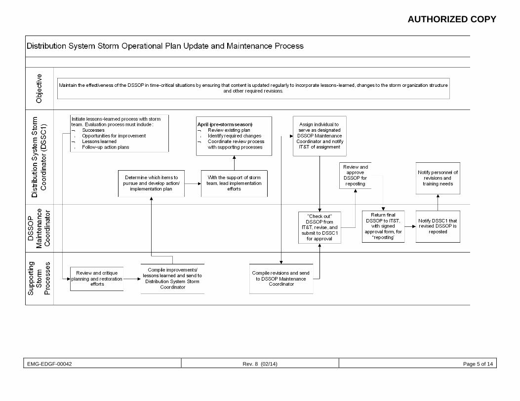
AUTHORIZED COPY
EMG-EDGF-00042 Rev. 8 (02/14) Page 5 of 14
AUTHORIZED COPY
EMG-EDGF-00042 Rev. 8 (02/14) Page 6 of 14
Approach to Storm Preparation Personal Safety Personal safety is a shared responsibility of all employees. The safety of our fellow employees as well as the safety of the general public and contract resources is the most important consideration when implementing any major emergency plan:
Under no circumstances will safety be sacrificed for speed. Job briefings are the cornerstone of all work to be performed safely and shall be utilized to identify
and mitigate all hazards associated with the work, following appropriate safe work practices. No employee shall attempt any restoration activity or establish staging sites where environmental or
weather conditions are deemed unsafe. Switching and tagging work rules shall be followed at all times, regardless of dispatching authority or
control. Work at night shall be well planned and organized.
Training The process owner of each storm organization is responsible for ensuring their personnel are assigned to a response role in the RSVP tool, are trained to the required responsibilities and are able to safely execute their assigned duties. Environmental Stewardship Duke Energy Florida has established itself as a good steward of the environment. Environmental concerns such as transformer oil and fuel spills must be reported immediately to the Zone level Environmental Lead or Coordinator. Spills should be contained as quickly as possible to mitigate damage to the environment, especially when waterways are at risk. Major Storm Damage to facilities may be caused by hurricanes, tornadoes, ice, and other natural causes or disaster, or the damage may be caused by civil disturbances. The use of the term “Major Storm”, as defined by IEEE Std 85901987; section 6.3.2 (page 10), indicates that weather has exceeded design limits of the facilities and results in all of the following:
1. Extensive damage to facilities 2. More than a percentage of customers out of service (10% or above) 3. Service restoration time is longer than a specified time (24 hours or above)
Note: Typical industry criteria are 10% of customers out of service and 24 hours or more restoration time. Percentage of customers out of service may be related to a company operating area rather than to an entire company. There are no specific measures for EXTENSIVE MECHANICAL damage. However, the term does not include electrical damage such as internal failures of transformers or conductors. Extensive refers to the magnitude of damage and the distance over which the damage extends. Therefore, it would be expected that the storm was of sufficient severity to cause damage of an unusual magnitude at multiple locations on the system.
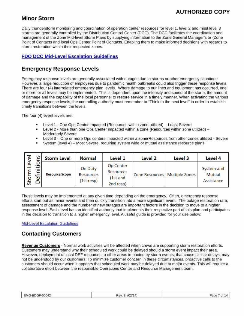
AUTHORIZED COPY
EMG-EDGF-00042 Rev. 8 (02/14) Page 7 of 14
Minor Storm Daily thunderstorm monitoring and coordination of operation center resources for level 1, level 2 and most level 3 storms are generally controlled by the Distribution Control Center (DCC). The DCC facilitates the coordination and management of the Zone Mid-level Storm Plans by supplying information to the Zone General Manager’s or (Zone Point of Contacts and local Ops Center Point of Contacts. Enabling them to make informed decisions with regards to storm restoration within their respected zones. FDO DCC Mid-Level Escalation Guidelines Emergency Response Levels Emergency response levels are generally associated with outages due to storms or other emergency situations. However, a large reduction of employees due to pandemic health outbreaks could also trigger these response levels. There are four (4) interrelated emergency plan levels. Where damage to our lines and equipment has occurred, one or more, or all levels may be implemented. This is dependent upon the intensity and speed of the storm, the amount of damage and the capability of the local personnel to restore service in a timely manner. When activating the various emergency response levels, the controlling authority must remember to “Think to the next level” in order to establish timely transitions between the levels. The four (4) event levels are:
Level 1 - One Ops Center impacted (Resources within zone utilized) - Least Severe Level 2 - More than one Ops Center impacted within a zone (Resources within zone utilized) –
Moderately Severe Level 3 – One or more Ops centers impacted within a zone(Resources from other zones utilized - Severe System (level 4) – Most Severe, requiring system wide or mutual assistance resource plans
These levels may be implemented at any given time depending on the emergency. Often, emergency response efforts start out as minor events and then quickly transition into a more significant event. The outage restoration rate, assessment of damage and the number of new outages are important factors in the decision to move to a higher response level. Each level has an identified authority that implements their respective part of this plan and participates in the decision to transition to a higher emergency level. A useful guide is provided for your use below: Mid-Level Escalation Guidelines Contacting Customers Revenue Customers - Normal work activities will be affected when crews are supporting storm restoration efforts. Customers may understand why their scheduled work could be delayed should a storm event impact their area. However, deployment of local DEF resources to other areas impacted by storm events, that cause similar delays, may not be understood by our customers. To minimize customer concern in these circumstances, proactive calls to the customers should occur when it appears that scheduled work may be delayed due to major events. This will require a collaborative effort between the responsible Operations Center and Resource Management team.
AUTHORIZED COPY
EMG-EDGF-00042 Rev. 8 (02/14) Page 8 of 14
Care Customers - Those accounts that are tagged “Life Support” in our CSS data base are to be contacted by the Customer Contact Operations (Call Center) prior to the arrival of a Tropical System. The purpose of this function is to ensure all potentially impacted Life Support customers are contacted and advised that Duke Energy Florida will be unable to provide priority restoration. In the advent of an extended outage due to the storm, these customers are to find alternate locations, such as shelters that are suitable for life support functions during the restoration effort. Weather Information Duke Energy Florida is supported by the Duke Meteorology Team. The Duke Meteorology Team provides daily weather updates and forecasts for major weather events. During approaching tropical events, the Duke Meteorology Team Weather provides daily graphical tracking maps and projections on wind and rain. The Distribution System Storm Center forwards this information to supporting storm organizations. In addition, these projections will be posted in the Current Storm Information folder located on the Duke Energy Florida Storm Center web page. Finally, the Duke Meteorology Team supports the DCC and Zone Operation and System storm conference calls with updated forecasts and projections for the approaching storm. Storm Escalation Awareness (Removed in the 2008 revision – information identified in Exhibit 1 – Storm Response Escalation Guidelines above) Storm Room Standards Storm rooms or storm centers are the command and control authority while the emergency response plan is in effect. For a system level response, the command and control hierarchy is as follows:
1. System Storm Center 2. Zone Level Storm Room 3. Operations Center Storm Room
Effective operation of a storm center or storm room is critical to efficient and speedy responses to emergency situations. The following guidelines should be utilized:
System Storm Center Timeline Storm Room Standards
Planning for Storm Events Restoration Priorities The following guidelines should be utilized by the Storm Process Owners to determine their restoration priorities:
Priority 1 – Feeders, lines and service drops for nuclear sirens, hospitals, municipal water & sewer treatment plants and emergency shelters.
Priority 2 – Feeders, lines and service drops for law enforcement, fire & rescue stations, central communications centers and food distribution centers.
Priority 3 - All other feeders, lines, service drops and equipment. Paralleling these priorities, are requirements for restoring communications links that facilitate the restoration of electric service. The Energy Delivery Group will assist IT&T by giving reasonable priority to electric facilities serving two-way radio sites, PBX sites, fiber optics and microwave sites, etc. In addition, the Delivery Operations Group will make resources available on a priority basis to support restoring fiber optic cables which carry communications traffic for the Company.
AUTHORIZED COPY
EMG-EDGF-00042 Rev. 8 (02/14) Page 9 of 14
Operational Restoration Performance The purpose is to assess conformance to DSSOP during a major storm restoration. Operational Performance Time-line Operational Performance Guiding Principles Operational Performance GIS Data Integrity
Maintaining the data integrity of our distribution information systems is important for day to day operational processes. Construction changes that occur during restoration efforts can negatively impact these information systems if not properly documented. These changes are more economically and efficiently documented at the time the construction change occurred. To avoid the need for a re-verification sweep of an area after the restoration effort has been completed, the Zone/Feeder Coordinator shall document these changes, using the form below, and forward to the local GIS contact. At the point during a mid-level or major storm (outage volume threshold) where the determination is made by the Person in charge at the ops center, zone, or system level as to whether the yards will stay in RTARM or revert to paper during restoration. Careful thought should be given prior to doing this as it causes a lot of manual work. Each ops center must either be using RTARM or using paper outage tickets. Reverting to paper when RTARM can be used should be the last resort. Any crews working on paper outage tickets, PE or contractors, will need to track the assets changed out via the storm procedure and inventory sheets on the link below. These sheets should be printed and carried with the crew.
GIS Data Form Distribution Control Center The Distribution Control Center (DCC) is responsible for monitoring the status of and issuing switching orders for system level distribution lines and equipment and underground loop designed facilities. As a major tropical system approaches or when restoration efforts require, the DCC may need to delegate their switching and tagging authority and/or dispatching authority for OMS and field equipment to appropriate Zone Storm Centers. The transferal of switching and tagging responsibility from the DCC to Zone Storm Centers and from Zone Storm Centers back to the DCC shall be documented utilizing the following form: Dispatch Function Transfer-Florida The use of the following document can be used as a guideline for delegating dispatching authority for OMS from the DCC to the responsible Zone/Ops Center storm centers: Delegation of Dispatch Authority OMS-Florida
AUTHORIZED COPY
EMG-EDGF-00042 Rev. 8 (02/14) Page 10 of 14
Resource Management The largest and most critical storm response resources are company employees and contractor line and tree crews. The efficient use of these valued resources directly affects the level of success with safety, timely restoration and cost for any restoration effort.
1) Duke Energy Florida Employee Mobilization and Tracking
In the event of a hurricane, major ice storm or other system emergencies, it may be necessary to deploy Duke Energy Florida employees across Departmental, Business Unit or Zone boundaries to support a timely restoration effort. The successful use of these resources requires precise communications between various groups and storm room/centers. The Resource Storm Volunteer Program (RSVP) is the authorized mobilization, tracking and release tool for Duke Energy Florida employees, non-line & tree contractors and activated retirees. Each storm organization and Department will identify a RSVP Coordinator and a backup to utilize and maintain the RSVP tool for major emergency responses. 2) On or Off System Crew Mobilization and Tracking
Resource Management is responsible for maintaining an updated list of contractors in the service area who have a contract agreement with the company. The Contract Manager is responsible for keeping an updated zone list of contractors available for use during a storm event to support restoration efforts. In the event of a hurricane, major ice storm or other system emergencies, it may be necessary to bring in off-system line and tree resources to support a timely restoration effort. The successful use of these resources requires precise communications and coordination between various storm rooms/centers. The Resource Link tool is the authorized mobilization, tracking and release tool for contract line and tree resources supporting Delivery Operations. The Resource Link tool shall be utilized by qualified employees at all affected Operations, Zone and System Storm Centers. Prior to releasing restoration personnel, a thorough ride-out inspection should be performed to ensure restoration repairs and tree work has been completed and any mitigation plans have been established. The following guideline should be used for the mobilization, tracking and release of off-system resources: Off-System Crew Mobilization Guidelines 3) Handling of Crews
Receiving Crews: Upon reporting for duty, the local Resource Management Coordinator should
evaluate each person’s work history to determine how many hours of work are available before rest should be scheduled. All prior hours worked, including travel time that have not been preceded by an eight hour rest period, should be counted.
Crew Utilization: The Operations Center Resource Management Coordinator is responsible for
making sure the location of each crew compliment is tracked during the storm restoration effort. Each off-system crew should have an assigned Zone/Feeder/Field Coordinator to monitor their work progress. Each crew lead/foreman should be supplied with the following:
• Local maps • Safety information and instructions • Emergency contact list • Local emergency facilities locations • Staging area maps/directions • Assigned feeder one lines
A minimum of 50 crew packages should be stored at each Operations Center. Additional information regarding laundry services, food services and lodging should be included, when applicable.
AUTHORIZED COPY
EMG-EDGF-00042 Rev. 8 (02/14) Page 11 of 14
Transferring Crews: When crews from other areas are in route, the Substation/Zone Coordinator will be given the name of the person in charge, the number of personnel, and the ETA by the Ops Center Resource Management Coordinator. The Substation/Zone Coordinator can then organize them into a work unit and assign a Feeder/Field Coordinator to receive them. The person in charge of the crew will give a list of names and equipment to the Feeder/Field Coordinator. The Feeder/Field Coordinator will verify the list and log the arrival time. Crews will not be released without consent from Substation/Zone Coordinator to do so. When crews are released, the Feeder/Field Coordinator will log their departure time. The Feeder/Field Coordinator in one area may be assigned to deliver the crew to a new Feeder/Field Coordinator in another area. No crews can be released to go off system or travel to another zone without the approval and direction from the System Resource Management Group.
Working Hours: Each Storm Process Owner will establish work shifts for those resources assigned to them. In the initial stages of the restoration effort it is general practice to work up to 24 hours, including travel time, without an extended rest period. As the 24 hour threshold approaches, each Process Owner will evaluate the extended response time needed and implement rotational shift assignments for all personnel, as needed. Operation Center Storm Coordinators should make assignments to utilize a minimum of 80% of their assigned work force during daylight and early evening hours and establish an eight (8) hour rest period, where practical, before beginning a new shift.
Creature Comforts: Rooms, laundry service, meals, drinks, etc., will be coordinated through the
System Logistics group by the Process Owners of each storm organization.
Vehicles & Equipment: If crew personnel are lodged for the evening, Logistics personnel will identify an area near the lodging establishment for the parking of line vehicles and equipment if the lodging establishment cannot accommodate them. Vehicles and equipment should be safely secured and where possible, security personnel or local police should be asked to patrol the area from time to time to reduce exposure to vandalism or theft.
Logistics - Staging & Mustering Sites The efficient staging of vehicles and equipment, and providing personnel with meals, medical care, fuel, material and sleeping quarters directly affects the level of success for any restoration effort. For all level 4 responses and in some Level 3 responses, the normal line & service facility is not able to coordinate the volume of resources required to restore service. For the Florida Service territory, the Zone Storm Managers are responsible for coordinating the identification of staging sites within their respective areas. Ideally, there should be at least two staging areas identified per Operations Centers; the second being available should the first site be flooded or otherwise not available.
The preferred staging site would be able to accommodate at least 500 linemen and 250 line trucks. The staging site should have a prepared layout that indicates traffic flow, security area, pole storage, transformer storage, re-fueling arrangements, old material storage, administrative space with supporting communications lines and equipment, restroom facilities (portable or fixed), electricity, lighting, water & ice storage and food preparation and eating area. These staging sites will normally be manned, maintained and managed by Logistics personnel specifically trained to these responsibilities. Damage Assessment Accurate and timely damage assessment information is critical to being able to plan our response efforts and to set accurate Estimated Time of Repairs (ETR’s) in our Outage Management Systems (OMS). In assessing damage, qualified employees and/or contractors will be dispatched to identify, document and report the type and severity of damage. In addition, damage assessors play an important role in identifying accounts that cannot receive service due to structural damage and reporting environmental spills to the Zone Environmental Lead or Coordinator.
AUTHORIZED COPY
EMG-EDGF-00042 Rev. 8 (02/14) Page 12 of 14
For level 4 storms, Centralized Damage Assessment teams are available to assist in this process. Normally, a two person Damage Assessment teams are dispatched to assist the Operations Center. To utilize these teams to their fullest, the Operations Center Storm Coordinator should have GIS maps available for the targeted feeders. The Damage Assessment teams will perform a damage assessment in statistically valid areas first, then patrol the target feeders and mark every pole, span of wire and transformer that is down. Line patrolling is performed by both vehicles and helicopters. Once these teams have done their damage assessment assignment they may be available to remain in the Operations Centers to serve as support resources.
Data Management Data Management plays an increasingly important role in the restoration effort from major events. This group is responsible for updating and tracking OMS outages and customers restored. Data Management is the authorized storm organization that supplies the outage information utilized by the Company for updating employees, customers, news channels and regulatory personnel on the progress of the restoration effort. The Tactical Management Coordinator in each Operations Center is responsible for seeing that this function is properly manned and managed. Truck and Vehicle Convoys
Duke Energy Florida’s Public Affairs group will initiate the procedures to ensure that state law enforcement agencies cooperate with our need to move trucks, vehicles and other equipment safely and quickly throughout the United States during major emergency responses. Public Affairs will ask state law enforcement officials to waive requirements that utility or contractor vehicles stop at weigh stations. In addition, a request will be made to suspend enforcement of fuel permits, size & weight restrictions, and other requirements for vehicles responding to the emergency. For additional details, see the following guideline: Storm Plan for Truck Convoys
Tracking of Road Closings
Efficiently transporting manpower, materials and fuel is dependent upon our knowledge of road closings. State DOT website postings for road closing information can be inaccurate and may not be up to date. Our local material delivery personnel, line & service employees and field support personnel develop accurate knowledge of road closings while performing their duties. The following procedure should be used to identify and track road closings reported by these individuals: 1. Each affected Zone Storm Center and the System Storm Center shall identify an individual in their center
that will act as the single point of contact for consolidating road closing information. 2. The Zone Storm Centers and the System Storm Center shall equally share responsibilities for
communicating road closing information. 3. All road closing information shall be sent to the System Storm Center contact, which should be
associated with the Crew Mobilization Team. 4. Road closing information shall be consolidated at the System Storm Center into one document titled
“Road Closings”. 5. The Road Closings document shall be posted and updated as necessary on the storm center intranet site
under Current Storm Information for use by traveling members of Duke Energy Florida.
AUTHORIZED COPY
EMG-EDGF-00042 Rev. 8 (02/14) Page 13 of 14
Post Response Plan and Functions 1) Post Emergency Response Recovery Plan – Once restoration efforts have been completed, the following should
be utilized as a guideline for establishing a prioritized work list:
Opening points should be identified and corrected to ensure the integrity of GIS and OMS. Primary phasing, recloser status and fuse and transformer size should be verified to ensure the
integrity of GIS and OMS. All DIS or GIS construction changes documented during the restoration effort shall be updated in
appropriate applications. Vegetation mitigation plan shall be developed and implemented with 10 days of completion of
restoration effort. Pending customer revenue work should be evaluated and rescheduled. Missing or damaged streetlight facilities should be identified and scheduled for repair or replacement. Significant amount of missing GIS numbers in an area should be replaced.
The following should be utilized to help establish a recovery plan:
Post Storm Recovery Plan 2) Clean up Crews - After a major emergency response has been completed, there is often a need to perform “clean-up work”. The work consists of straightening leaning poles, re-sagging lines, re-installing or repairing streetlight fixtures, cutting danger limbs and/or trees and correcting any temporary repairs. The best resource that can be utilized for this work may be the off-system contract crews that can be held over. However, the cost of these resources and any mutual assistance agreements should be considered before utilizing them for this work. The Resource Management Team at the System Storm Center shall identify which contract resources are available for being held over and will work with the zone and operations center management team to develop a plan to efficiently complete this work. 3) Tree Removal Policy – When restoring power to customers as quickly as possible after a major event, line and tree crews cut trees and limbs off and away from power lines and equipment and leave the debris laying in place. Duke Energy Florida does not provide tree debris removal during storm restoration. Customers needing downed trees and limbs removed from their property should contact local tree contractors. Also, Duke Energy Florida does not remove any danger trees during storm restoration unless they pose an immediate threat to our facilities. 4) Revenue Customer Callbacks – Normal work activities will be affected when crews are supporting other areas during emergency responses. Customers may understand why their work could be delayed when they see a storm damage their area; however, when the storm hits elsewhere, customers may not readily tolerate delays in regular work caused by deploying local resources to those hard hit areas. To minimize customer concern in these circumstances, proactively call customers when it appears that regularly scheduled work may be delayed. This requires collaborative effort between the Operations Center and the Customer Service Center. 5) Grid Modernization Infrastructure – As a major emergency response nears completion, there is often a need to perform “Grid Mod clean-up work”. The work consists of Connection to Distribution power source, remounting the Nan device to the pole, antenna connections and reconnection of cable to the battery Access Power Units. The best resource that can be utilized for this work may be the off-system contract crews that can be held over. However, the cost of these resources and any mutual assistance agreements should be considered before utilizing them for this work. The Resource Management Team at the System Storm Center shall identify which contract resources are available for being held over and will work with the zone and operations center management team to develop a plan to efficiently complete this work. FDO Interim RDR AMI Florida Storm Response Plan Extended Pay Procedures The corporate extended pay policy can be applied to major storm and other system level emergency work. If applicable, these procedures will be initiated and implemented by the Human Resources.
AUTHORIZED COPY
EMG-EDGF-00042 Rev. 8 (02/14) Page 14 of 14
See individual storm organization storm plans below:
Table of Contents
Section 1 –Distribution System Storm Center (DSSC) - EMG-EDGF-00043 Section 2 - Staging and Logistics (SL) - EMG-EDGF-00044 Section 3 – Corporate Communications (CC) - EMG-EDGF-00045 Section 4 – Corporate Security (CS) – EMG-EDGX-00046 Section 5 – Accounting Storm Team – EMG-EDGF-00047 Section 6 – Damage Assessment (DA) – EMG-EDGF-00048 Section 7 – Customer and Community Relations (CR) – EMG-EDGF-00050 Section 8 – Distribution Control Center (DCC) – EMG-EDGF-00051 Section 9 – Resource Management (RM) – EMG-EDGF-00052 Section 10 – Performance Support (PS) - EMG-EDGF-00053 Section 11 – Zone (REG) – EMG-EDGF-00054 Section 12 – Operations (OPS) –EMG-EDGF-00055 Section 13 – Support Services (SS) – EMG-EDGF-00057 Section 14 – Safety Team (SAF) – EMG-EDGF-00058 Section 15 – Human Resources (HR) – EMG-EDGF-00059 Appendix A – Key Performance Indicators – EMG-EDGF-00060 Appendix C – System Matrix – EMG-EDGF-00062 Appendix D – Abbreviations – EMG-EDGF-00063
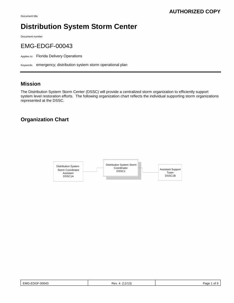
AUTHORIZED COPY
EMG-EDGF-00043 Rev. 4 (11/13) Page 1 of 9
Document title
Distribution System Storm Center Document number
EMG-EDGF-00043 Applies to: Florida Delivery Operations Keywords: emergency; distribution system storm operational plan
Mission The Distribution System Storm Center (DSSC) will provide a centralized storm organization to efficiently support system level restoration efforts. The following organization chart reflects the individual supporting storm organizations represented at the DSSC.
Organization Chart
Distribution System Storm Coordinator
DSSC1 Distribution System Storm Coordinator
Assistant DSSC1A
Assistant Support Team
DSSC1B
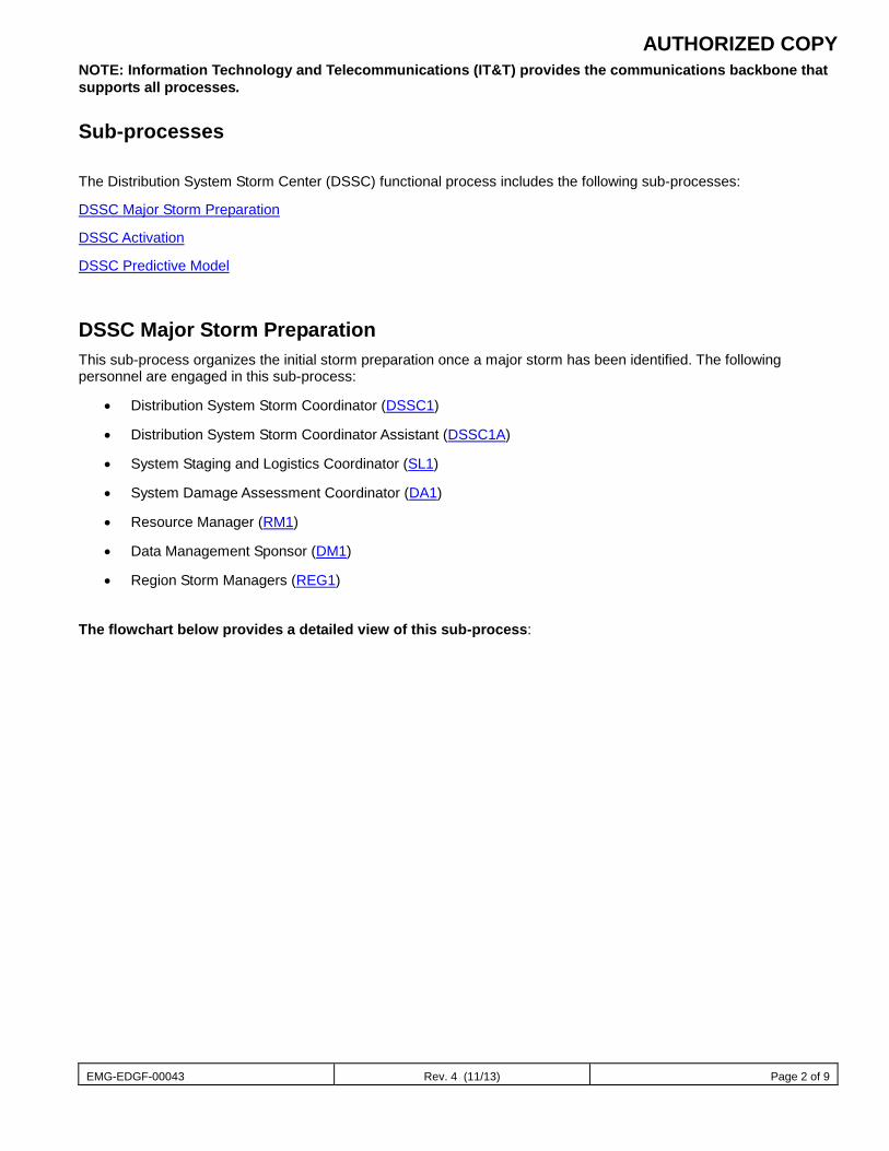
AUTHORIZED COPY
EMG-EDGF-00043 Rev. 4 (11/13) Page 2 of 9
NOTE: Information Technology and Telecommunications (IT&T) provides the communications backbone that supports all processes.
Sub-processes The Distribution System Storm Center (DSSC) functional process includes the following sub-processes:
DSSC Major Storm Preparation
DSSC Activation
DSSC Predictive Model
DSSC Major Storm Preparation This sub-process organizes the initial storm preparation once a major storm has been identified. The following personnel are engaged in this sub-process:
• Distribution System Storm Coordinator (DSSC1)
• Distribution System Storm Coordinator Assistant (DSSC1A)
• System Staging and Logistics Coordinator (SL1)
• System Damage Assessment Coordinator (DA1)
• Resource Manager (RM1)
• Data Management Sponsor (DM1)
• Region Storm Managers (REG1)
The flowchart below provides a detailed view of this sub-process:
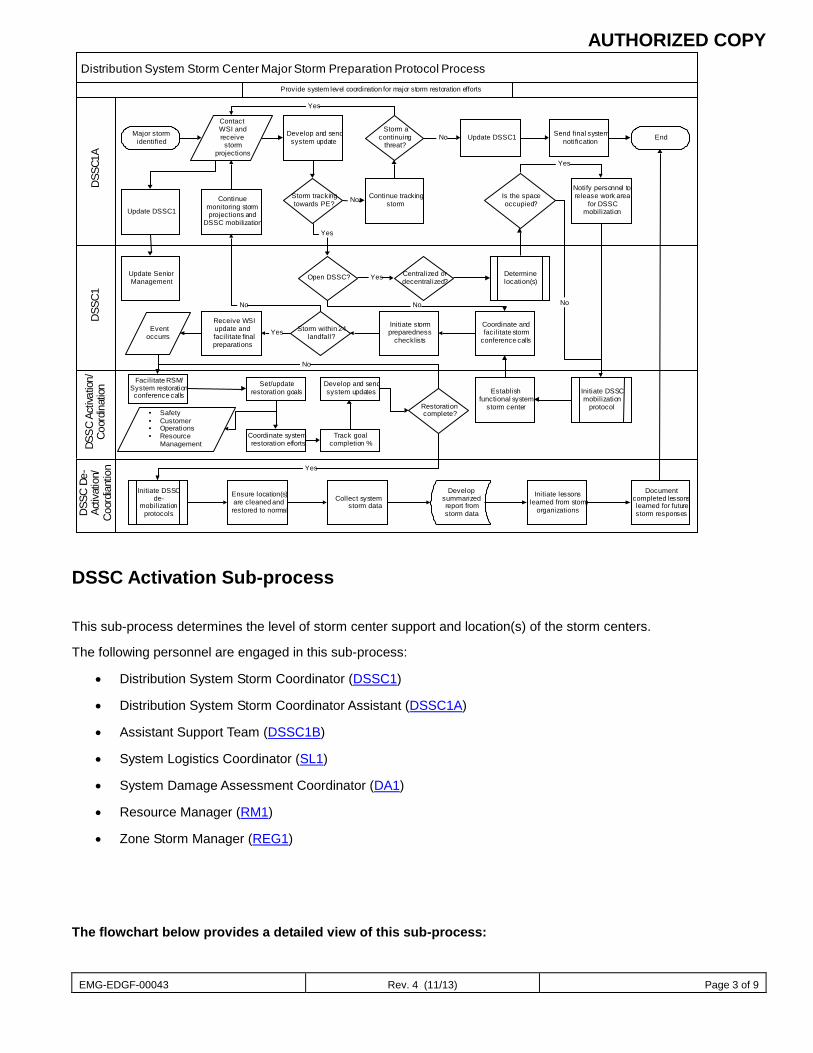
AUTHORIZED COPY
EMG-EDGF-00043 Rev. 4 (11/13) Page 3 of 9
Distribution System Storm Center Major Storm Preparation Protocol Process
DSS
C1DS
SC
Activ
atio
n/Co
ordin
ation
DSS
CDe
-Ac
tivat
ion/
Coo
rdia
ntio
nD
SSC1
A
Major stormidentified
ContactWSI andreceive
stormprojections
Update DSSC1
Develop and sendsystem update
Storm trackingtowards PE?
Open DSSC?
Yes
Continue trackingstorm
Storm acontinuing
threat?End
Yes
No
Update SeniorManagement
Update DSSC1 Send final systemnotificationNo
Yes Centralized ordecentralized?
Is the spaceoccupied?
Notify personnel torelease work area
for DSSCmobilization
Initiate DSSCmobilization
protocol
Yes
Coordinate andfacilitate storm
conference calls
No
Establishfunctional system
storm center
Initiate stormpreparedness
checklists
Storm within 24landfall?
Continuemonitoring stormprojections and
DSSC mobilization
Receive WSIupdate andfacilitate finalpreparations
YesEventoccurrs
Facilitate RSM/System restorationconference calls
Set/updaterestoration goals
Coordinate systemrestoration efforts
No
Track goalcompletion %
Develop and sendsystem updates
Restorationcomplete?
No
Initiate DSSCde-
mobilizationprotocols
Yes
Ensure location(s)are cleaned andrestored to normal
Collect systemstorm data
Initiate lessonslearned from storm
organizations
Documentcompleted lessonslearned for futurestorm responses
Determinelocation(s)
Developsummarizedreport fromstorm data
Safety Customer Operations Resource
Management
No
Provide system level coordination for major storm restoration efforts
DSSC Activation Sub-process This sub-process determines the level of storm center support and location(s) of the storm centers.
The following personnel are engaged in this sub-process:
• Distribution System Storm Coordinator (DSSC1)
• Distribution System Storm Coordinator Assistant (DSSC1A)
• Assistant Support Team (DSSC1B)
• System Logistics Coordinator (SL1)
• System Damage Assessment Coordinator (DA1)
• Resource Manager (RM1)
• Zone Storm Manager (REG1)
The flowchart below provides a detailed view of this sub-process:
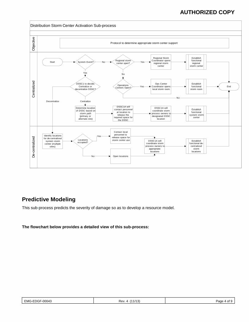
AUTHORIZED COPY
EMG-EDGF-00043 Rev. 4 (11/13) Page 4 of 9
Distribution Storm Center Activation Sub-process
Cen
traliz
edDe
-cen
traliz
edO
bjec
tive
Protocol to determine appropriate storm center support
Start System Event?
Identify locationsfor de-centralized
system stormcenter (multiple
sites)
Determine locationof DSSC based on
storm path(primary or
alternate site)
Regional stormcenter open?
Regional StormCoordinator opens
regional stormcenter
Yes
End
DSSC1A willcontact personnel
at location torelease the
required space forthe DSSC
DSSC1A willcoordinate storm
process owners todesignated DSSC
location
OperationsCenters Open?
Ops CenterCoordinator openslocal storm room
Yes
No
DSSC1 to decide;Centralize or
decentralize DSSC?
Yes
Decentralize Centralize
No
No
Establishfunctionalregional
storm center
Establishfunctional
system stormcenter
Establishfunctional
storm room
Locationsoccupied?
Contact localpersonnel to
release space forstorm center use
Yes
No Open locations
DSSC1A willcoordinate storm
process owners toappropriatelocations
Establishfunctional de-
centralizedstorm
locations
Predictive Modeling This sub-process predicts the severity of damage so as to develop a resource model.
The flowchart below provides a detailed view of this sub-process:
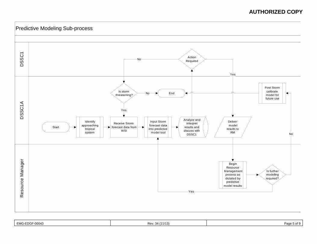
AUTHORIZED COPY
EMG-EDGF-00043 Rev. 34 (11/13) Page 5 of 9
Predictive Modeling Sub-processD
SS
C1
Res
ourc
e M
anag
erD
SSC
1A
Start
Identifyapproaching
tropicalsystem
Receive Stormforecast data from
WSI
Input Stormforecast datainto predictive
model tool
Analyze andinterpret
results anddiscuss with
DSSC1
ActionRequired
Delivermodel
results toRM
BeginResource
Managementprocess asdictated bypredictive
model results
Is furthermodelingrequired?
Post Stormcalibratemodel forfuture use
End
Yes
No
Yes
Is stormthreatening? No
Yes
No
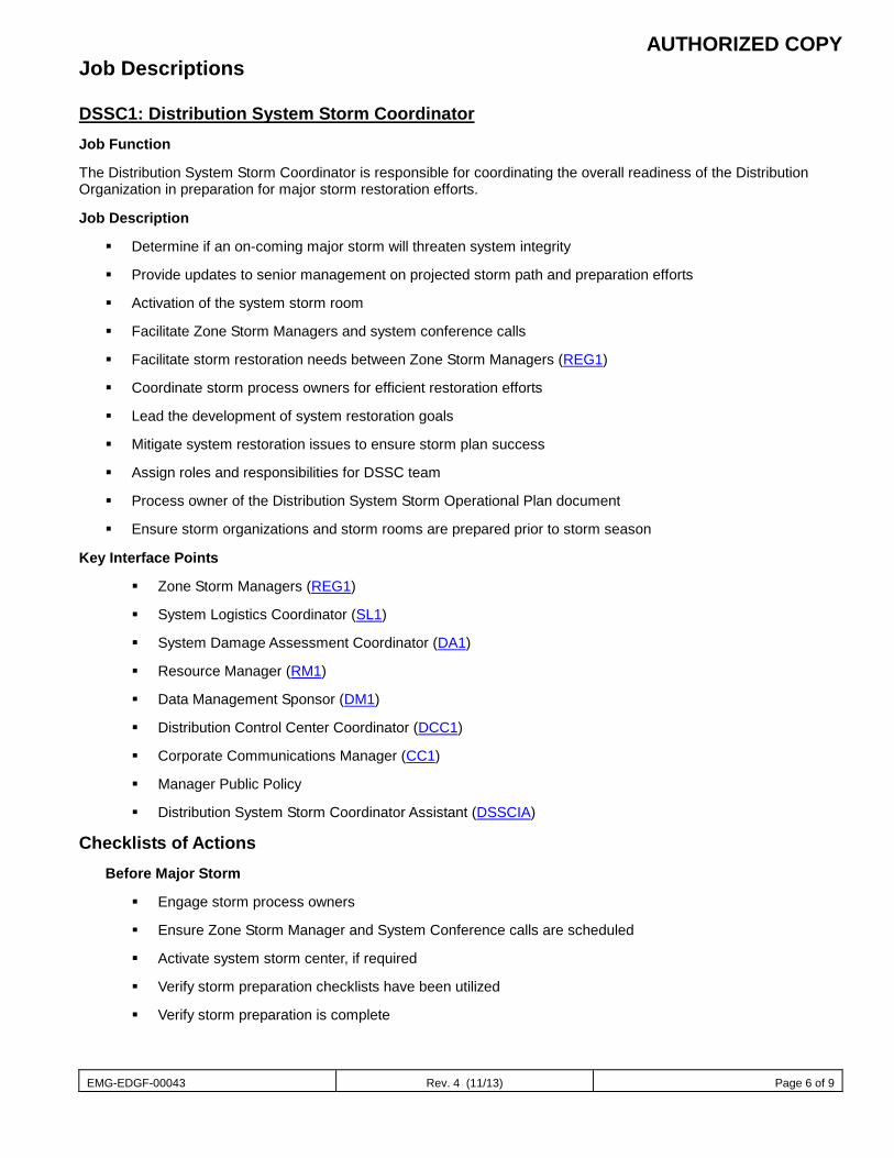
AUTHORIZED COPY
EMG-EDGF-00043 Rev. 4 (11/13) Page 6 of 9
Job Descriptions
DSSC1: Distribution System Storm Coordinator Job Function
The Distribution System Storm Coordinator is responsible for coordinating the overall readiness of the Distribution Organization in preparation for major storm restoration efforts.
Job Description
Determine if an on-coming major storm will threaten system integrity
Provide updates to senior management on projected storm path and preparation efforts
Activation of the system storm room
Facilitate Zone Storm Managers and system conference calls
Facilitate storm restoration needs between Zone Storm Managers (REG1)
Coordinate storm process owners for efficient restoration efforts
Lead the development of system restoration goals
Mitigate system restoration issues to ensure storm plan success
Assign roles and responsibilities for DSSC team
Process owner of the Distribution System Storm Operational Plan document
Ensure storm organizations and storm rooms are prepared prior to storm season
Key Interface Points
Zone Storm Managers (REG1)
System Logistics Coordinator (SL1)
System Damage Assessment Coordinator (DA1)
Resource Manager (RM1)
Data Management Sponsor (DM1)
Distribution Control Center Coordinator (DCC1)
Corporate Communications Manager (CC1)
Manager Public Policy
Distribution System Storm Coordinator Assistant (DSSCIA)
Checklists of Actions Before Major Storm
Engage storm process owners
Ensure Zone Storm Manager and System Conference calls are scheduled
Activate system storm center, if required
Verify storm preparation checklists have been utilized
Verify storm preparation is complete
AUTHORIZED COPY
EMG-EDGF-00043 Rev. 4 (11/13) Page 7 of 9
During Major Storm
Facilitate conference calls
Facilitate and track restoration goal performance – mitigate issues
Provide updates to Senior management
After Major Storm
Facilitate release of off-system resources
Sponsor storm restoration summaries
Sponsor lessons learned request from process owners
Verify results of lessons learned has been documented and institutionalized
Engaged in the Following Sub-processes:
• DSSC Major Storm Preparation
• DSSC Activation
DSSC1A – Distribution System Storm Coordinator Assistant Job Function
The Distribution System Storm Coordinator Assistant is responsible for coordinating the activation of the system storm room and providing direct support to the Distribution System Storm Coordinator (DSSC1) for major storm restoration efforts.
Job Description
Understand the Corporate Storm Plan (EMG-EDGX-00010) and the Distribution System Storm Operational Plan (EMG-EDGF-00042)
Is the DSSOP Maintenance Coordinator
Generate predictive resource model based on the Weather Service Provider wind projections
Facilitate system storm preparations prior to storm season
Lead Distribution System Storm Center activation and de-activation
Schedule and participate in the Zone Storm Manager and System Conference calls
Engage the Weather Service Provider for storm tracking, wind and precipitation projections
Develop and issue system notifications for impending storms, on-system storm restoration efforts and off-system support through the mutual assistance agreement
Collect storm restoration summary data and prepare system storm presentations
Facilitate lessons learned after each storm and incorporate into storm plans
Present Major Storm Plan presentation for New Employee Orientation meetings
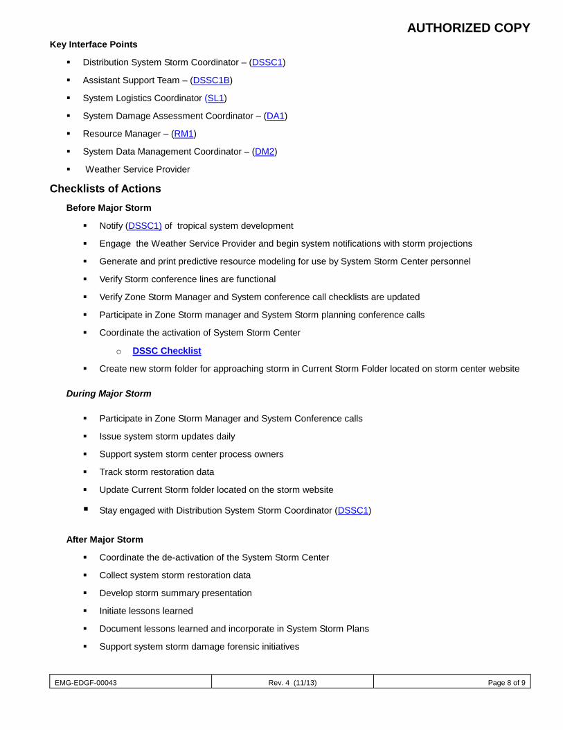
AUTHORIZED COPY
EMG-EDGF-00043 Rev. 4 (11/13) Page 8 of 9
Key Interface Points
Distribution System Storm Coordinator – (DSSC1)
Assistant Support Team – (DSSC1B)
System Logistics Coordinator (SL1)
System Damage Assessment Coordinator – (DA1)
Resource Manager – (RM1)
System Data Management Coordinator – (DM2)
Weather Service Provider
Checklists of Actions Before Major Storm
Notify (DSSC1) of tropical system development
Engage the Weather Service Provider and begin system notifications with storm projections
Generate and print predictive resource modeling for use by System Storm Center personnel
Verify Storm conference lines are functional
Verify Zone Storm Manager and System conference call checklists are updated
Participate in Zone Storm manager and System Storm planning conference calls
Coordinate the activation of System Storm Center
o DSSC Checklist
Create new storm folder for approaching storm in Current Storm Folder located on storm center website During Major Storm
Participate in Zone Storm Manager and System Conference calls
Issue system storm updates daily
Support system storm center process owners
Track storm restoration data
Update Current Storm folder located on the storm website
Stay engaged with Distribution System Storm Coordinator (DSSC1) After Major Storm
Coordinate the de-activation of the System Storm Center
Collect system storm restoration data
Develop storm summary presentation
Initiate lessons learned
Document lessons learned and incorporate in System Storm Plans
Support system storm damage forensic initiatives
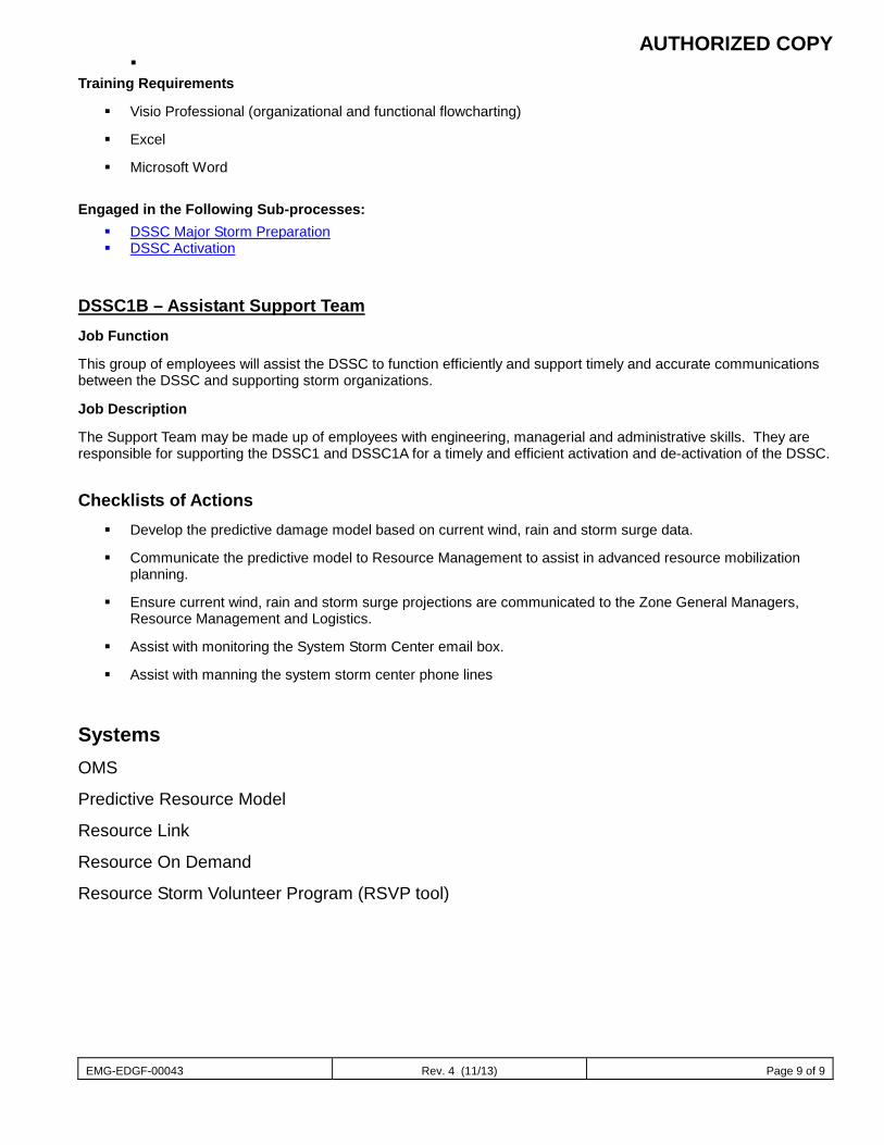
AUTHORIZED COPY
EMG-EDGF-00043 Rev. 4 (11/13) Page 9 of 9
Training Requirements
Visio Professional (organizational and functional flowcharting)
Excel
Microsoft Word
Engaged in the Following Sub-processes: DSSC Major Storm Preparation DSSC Activation
DSSC1B – Assistant Support Team Job Function
This group of employees will assist the DSSC to function efficiently and support timely and accurate communications between the DSSC and supporting storm organizations.
Job Description
The Support Team may be made up of employees with engineering, managerial and administrative skills. They are responsible for supporting the DSSC1 and DSSC1A for a timely and efficient activation and de-activation of the DSSC.
Checklists of Actions Develop the predictive damage model based on current wind, rain and storm surge data.
Communicate the predictive model to Resource Management to assist in advanced resource mobilization planning.
Ensure current wind, rain and storm surge projections are communicated to the Zone General Managers, Resource Management and Logistics.
Assist with monitoring the System Storm Center email box.
Assist with manning the system storm center phone lines
Systems OMS
Predictive Resource Model
Resource Link
Resource On Demand
Resource Storm Volunteer Program (RSVP tool)
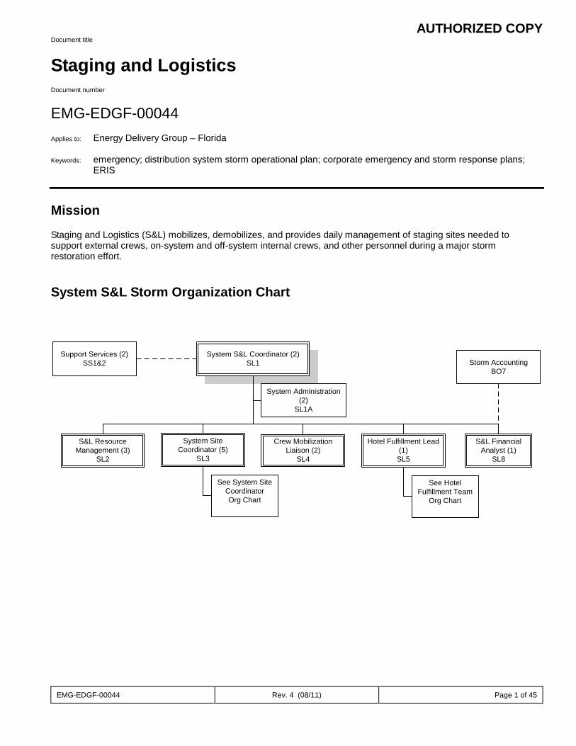
AUTHORIZED COPY
EMG-EDGF-00044 Rev. 4 (08/11) Page 1 of 45
Document title
Staging and Logistics Document number
EMG-EDGF-00044 Applies to: Energy Delivery Group – Florida Keywords: emergency; distribution system storm operational plan; corporate emergency and storm response plans;
ERIS Mission
Staging and Logistics (S&L) mobilizes, demobilizes, and provides daily management of staging sites needed to support external crews, on-system and off-system internal crews, and other personnel during a major storm restoration effort.
System S&L Storm Organization Chart
System S&L Coordinator (2)SL1
System Administration (2)
SL1A
Support Services (2)SS1&2
System Site Coordinator (5)
SL3
Crew Mobilization Liaison (2)
SL4
S&L Resource Management (3)
SL2
Storm AccountingBO7
Hotel Fulfillment Lead (1)
SL5
See System Site Coordinator Org Chart
See Hotel Fulfillment Team
Org Chart
S&L Financial Analyst (1)
SL8
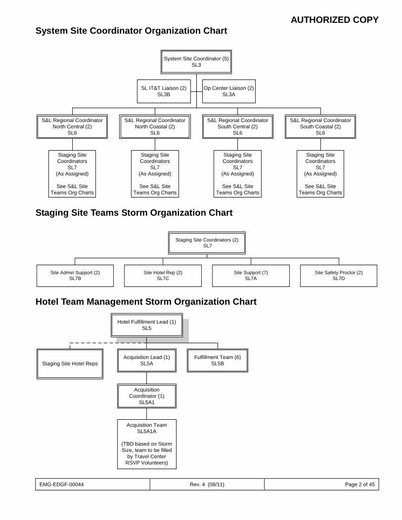
AUTHORIZED COPY
EMG-EDGF-00044 Rev. 4 (08/11) Page 2 of 45
System Site Coordinator Organization Chart
System Site Coordinator (5)SL3
S&L Regional CoordinatorSouth Coastal (2)
SL6
S&L Regional CoordinatorSouth Central (2)
SL6
S&L Regional CoordinatorNorth Central (2)
SL6
S&L Regional CoordinatorNorth Coastal (2)
SL6
Op Center Liaison (2)SL3A
SL IT&T Liaison (2)SL3B
Staging Site Coordinators
SL7(As Assigned)
See S&L Site Teams Org Charts
Staging Site Coordinators
SL7(As Assigned)
See S&L Site Teams Org Charts
Staging Site Coordinators
SL7(As Assigned)
See S&L Site Teams Org Charts
Staging Site Coordinators
SL7(As Assigned)
See S&L Site Teams Org Charts
Staging Site Teams Storm Organization Chart
Staging Site Coordinators (2) SL7
Site Admin Support (2)SL7B
Site Hotel Rep (2)SL7C
Site Support (7)SL7A
Site Safety Proctor (2)SL7D
Hotel Team Management Storm Organization Chart
Hotel Fulfillment Lead (1)SL5
Acquisition Lead (1)SL5AStaging Site Hotel Reps
Fulfillment Team (6)SL5B
Acquisition Team SL5A1A
(TBD based on Storm Size, team to be filled
by Travel Center RSVP Volunteers)
Acquisition Coordinator (1)
SL5A1
AUTHORIZED COPY
EMG-EDGF-00044 Rev. 4 (08/11) Page 3 of 45
Staging & Logistics Sub-Processes
The S&L functional process includes the following sub-processes: Hotel Procurement Staging Site Mobilization and Demobilization Daily Staging Site Management Hotel Procurement Sub-Process
This sub-process acquires and cancels hotel rooms for crews and other support personnel based on requests from the Fulfillment Team.
The following personnel are engaged in Hotel Procurement: Acquisition Lead (SL5A) Hotel Acquisition Coordinator (SL5A1) Acquisition Team (SL5A1A) Fulfillment Team (SL5B)
Acquisition Lead (SL5A) Coordinate/troubleshoot activities with Hotel Fulfillment Lead Instruct Hotel Acquisition Coordinator and RSVP Volunteers to prepare for possible deployment Manage the daily activities of the Storm Travel Team and report to Hotel Fulfillment as necessary
Hotel Acquisition Coordinator (SL5A1) Instruct RSVP volunteers on hotel reservation/hotel cancellations from Hotel Fulfillment
Review requests for completeness Contact Hotel Fulfillment with questions Give hotel reservation/hotel cancellations to appropriate RSVP Volunteer Receive completed hotel reservations/hotel cancellations from RSVP Volunteer
Review form for completeness Contact RSVP Volunteer with questions Ensure completed requests are submitted in the Storm Hotel Reservation system to Hotel Fulfillment
Acquisition Team (SL5A1A) Receive hotel reservations/hotel cancellations from Hotel Acquisition Coordinator Locate, call, and book/cancel hotel rooms using Hotel Prioritization listings Complete hotel reservations/hotel cancellations Return completed hotel reservations/hotel cancellations to Tool Administrator
Hotel Fulfillment Team (SL5B) Receive data from Hotel Fulfillment Lead with number of hotel beds required for crews and support personnel Complete and submit Hotel Reservation Request Form/ Hotel Cancellation Request Form to Hotel Acquisition
Hotel Reservation Request is identified by Staging Site/Operation Center/City Hotel Cancellation Request is identified by Staging Site/Operation Center/City including Hotel Name
Assist Staging Site Hotel Representative with questions and process of acquiring Hotel Lists from the Hotel Tool. The flowchart below provides a detailed view of this sub-process:
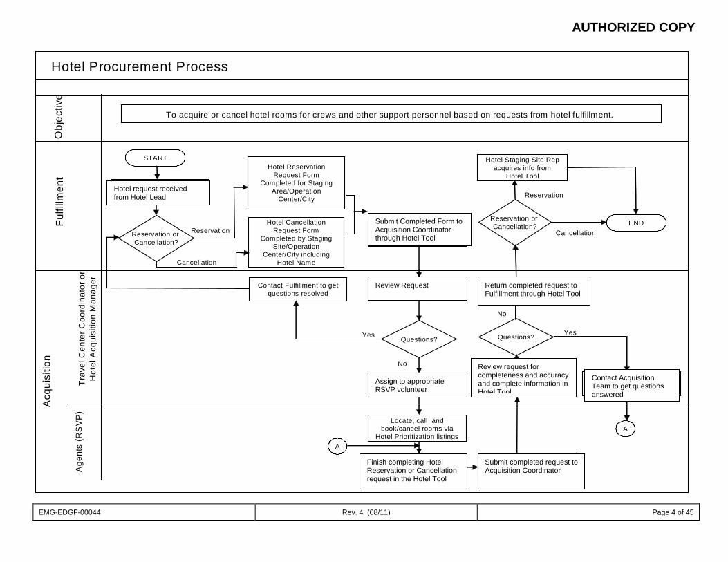
AUTHORIZED COPY
EMG-EDGF-00044 Rev. 4 (08/11) Page 4 of 45
Hotel Procurement ProcessO
bjec
tive
Age
nts
(RS
VP
)T
rave
l Cen
ter
Coo
rdin
ator
or
Hot
el A
cqui
sitio
n M
anag
er
Fulfi
llmen
tA
cqui
sitio
n
To acquire or cancel hotel rooms for crews and other support personnel based on requests from hotel fulfillment.
START
Hotel request received from Hotel Manager
Hotel Reservation Request Form
Completed for Staging Area/Operation
Center/City
Cancellation
Reservation or Cancellation?
ReservationHotel Cancellation
Request Form Completed by Staging
Site/Operation Center/City including
Hotel Name
Submit Completed Form to Acquisition (Storm –
Travel)
Review form for completeness and
accuracy
Input in Hotel Tool and assign to appropriate
agent
Locate, call and book/cancel rooms via
Hotel Prioritization listings
No
Questions?Yes
Finish completing Hotel Reservation or
Cancellation Form
YesQuestions?
No
Submit Completed Form to Acquisition
Review form for completeness and
accuracy and complete information in Hotel Tool
Contact Agent to get questions resolved
Contact Fulfillment to get questions resolved
A
A
Return Completed Form to Fulfillment
Hotel Staging Site Rep acquires info from
Hotel Tool
Reservation or Cancellation?
Reservation
ENDCancellation
Submit Completed Form to Acquisition Coordinator through Hotel Tool
Hotel request received from Hotel Lead
Assign to appropriate RSVP volunteer
Review Request
Finish completing Hotel Reservation or Cancellation request in the Hotel Tool
Submit completed request to Acquisition Coordinator
Review request for completeness and accuracy and complete information in Hotel Tool
Contact Acquisition Team to get questions answered
Return completed request to Fulfillment through Hotel Tool
AUTHORIZED COPY
EMG-EDGF-00044 Rev. 4 (08/11) Page 5 of 45
Staging Site Mobilization and Demobilization This sub-process provides direction for the mobilization and demobilization of staging sites during a major storm
restoration effort.
The following personnel are engaged in Staging Site Mobilization and Demobilization:
System S&L Coordinator (SL1) System Site Coordinator (SL3) S&L Resource Manager (SL2) S&L Regional Coordinators (SL6) Staging Site Coordinators (SL7)
Staging Site Mobilization Process System S&L Coordinator (SL1) Notify Supporting Storm Organizations and System S&L Team that company is on storm watch and to begin
preparation for possible deployment. Conduct System S&L Storm call and coordinate communication with Supply Chain
Sites to be opened Estimated number of outside resources
System Site Coordinator (SL3) Request initial site complement from Supply Chain via Staging Site Request Form. Includes:
Site rental car needs Initial site security needs Initial site set up needs
Act as liaison between Supply Chain and S&L Regional Coordinators Address additional site needs and communicate with S&L Regional Coordinators and Staging Site Coordinators
S&L Resource Manager (SL2) Instruct Staging Site Coordinators to prepare for possible deployment and determine availability of their team
members Assign Staging Site Coordinators to activated staging sites Deploy S&L Staging Site teams to activated staging sites Track Resource Movement within S&L
S&L Regional Coordinators (SL6) Communicate additional Regional staging needs to the System Site Coordinator (see Staging Site Request form
for asset list) Mitigate issues and ensure Regional needs are being met
Staging Site Coordinators (SL7) Initiate and establish communications with S&L Site team members Obtain Flash Drive from S&L IT Support with up-to-date Team Lead Manual download Obtain assigned S&L Staging Site Map information Obtain all required S&L Site Kits (IT Kit, Office Supply Kit, Site Safety Kits ) Initiate and establish communications with S&L Staging Site contacts Set-up S&L Staging Site area per S&L Site Map Ensure S&L team members report to S&L Site and bring Personal Storm Kits Initiate and establish communications with Safety Client Manager and Site Safety Proctor Initiate and establish communications with on-site Security Liaison Maintain communications with Regional S&L Coordinator Validate initial S&L Staging Site inventory and expenses
AUTHORIZED COPY
EMG-EDGF-00044 Rev. 4 (08/11) Page 6 of 45
Staging Site Demobilization Process
System S&L Coordinator (SL1) • Notify Supporting Storm Organizations and System S&L Team that staging sites are closing
System Site Coordinator (SL3) Support System S&L Coordinator with communicating demobilization requests to S&L Regional Coordinators Notify Supporting Organizations of sites closing and ensure all materials and vendor equipment is picked
up/returned
S&L Resource Manager (SL2) Reassign/release Staging Site Team as needed
S&L Regional Coordinators (SL6) • Instruct Staging Site Coordinators to begin demobilization of staging sites • Coordinate transition of remaining contract crews to Operating Center Contact Person
Provide maps indicating hotel options with phone numbers and addresses (Streets & Trips search by Op Center)
Staging Site Coordinators (SL7) Complete Staging Site/Mustering Site Rating Form Final inventory of items on site Final entry in “DEF and PEC S&L Site Tracking Tool” Collect all S&L Site Kits and inventory remaining items Return storm card to Storm Card Administrator Reconcile storm card expenses and submit all receipts to Storm Card Administrator Contact S&L Regional Coordinators to verify all Demobilization procedures are complete Conduct Exit Interviews Work in conjunction with Regional Utilization Coordinators (RUC’s), S&L Regional Coordinators, and S&L System
Site Coordinator to ensure staging site property owners are satisfied with site clean up
Supporting Storm Organizations • Supply Chain contacts vendors with 24 hour notice to remove all equipment from Staging Sites • Supply Chain notifies Staging Site Coordinator and Security Command Center of the schedule for equipment
removal Security coverage will continue until removal of the equipment up to 24 hours after time stamped termination of
rental service
The flowcharts below provide a detailed view of this sub-process:
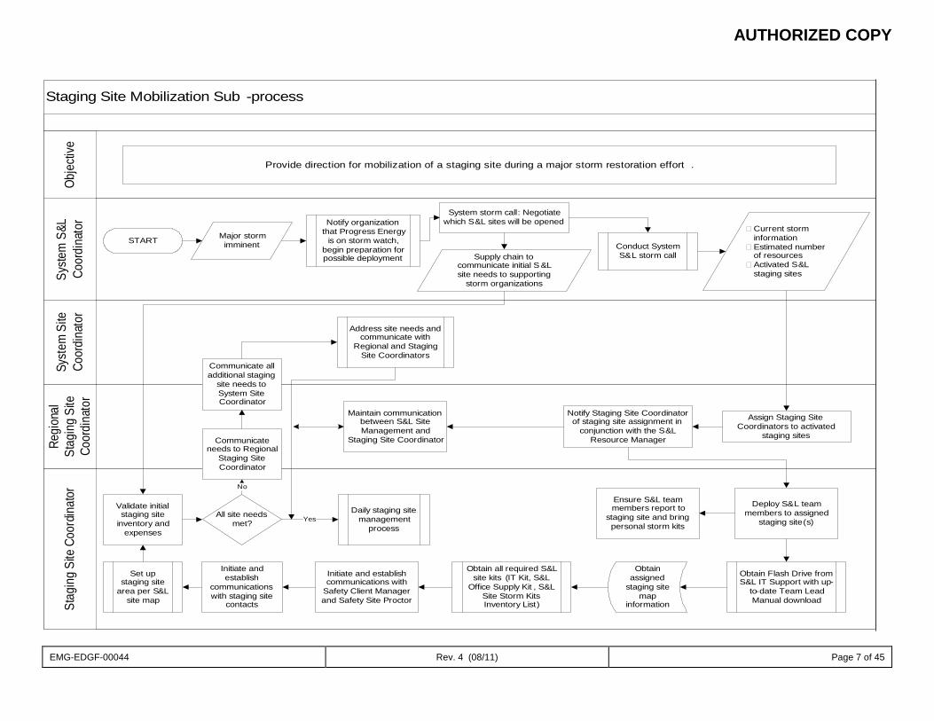
AUTHORIZED COPY
EMG-EDGF-00044 Rev. 4 (08/11) Page 7 of 45
Staging Site Mobilization Sub -process
Syste
m S
&L
Coor
dina
tor
Syst
em S
ite
Coor
dina
tor
Regi
onal
St
agin
g Si
te
Coor
dina
tor
Stag
ing
Site
Coo
rdin
ator
Obje
ctive
Provide direction for mobilization of a staging site during a major storm restoration effort .
START Major storm imminent
Notify organization that Progress Energy
is on storm watch, begin preparation for possible deployment
System storm call: Negotiate which S&L sites will be opened
Supply chain to communicate initial S &L site needs to supporting
storm organizations
Conduct System S&L storm call
Current storm information
Estimated number of resources
Activated S&L staging sites
Validate initial staging site
inventory and expenses
All site needs met?
Daily staging site management
processYes
Communicate needs to Regional
Staging Site Coordinator
No
Communicate all additional staging
site needs to System Site Coordinator
Address site needs and communicate with
Regional and Staging Site Coordinators
Maintain communication between S&L Site Management and
Staging Site Coordinator
Assign Staging Site Coordinators to activated
staging sites
Notify Staging Site Coordinator of staging site assignment in
conjunction with the S&L Resource Manager
Deploy S&L team members to assigned
staging site(s)
Ensure S&L team members report to
staging site and bring personal storm kits
Initiate and establish communications with
Safety Client Manager and Safety Site Proctor
Obtain Flash Drive from S&L IT Support with up-
to-date Team Lead Manual download
Obtain all required S&L site kits (IT Kit, S&L
Office Supply Kit , S&L Site Storm Kits Inventory List)
Obtain assigned
staging site map
information
Initiate and establish
communications with staging site
contacts
Set up staging site
area per S&L site map
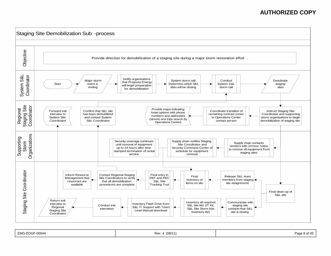
AUTHORIZED COPY
EMG-EDGF-00044 Rev. 4 (08/11) Page 8 of 45
Staging Site Demobilization Sub -process
Syste
m S
&L
Coor
dina
tor
Regi
onal
St
agin
g Si
te
Coor
dina
tor
Supp
ortin
g St
orm
Or
ganiz
atio
nsSt
agin
g Si
te C
oord
inat
orOb
jecti
ve
Provide direction for demobilization of a staging site during a major storm restoration effort .
StartMajor storm
event is ending
Notify organizations that Progress Energy will begin preparation
for demobilization
System storm call: Determine which S&L sites will be closing
Conduct System S&L
storm call
Deactivate staging
sites
Instruct Staging Site Coordinator and supporting storm organizations to begin demobilization of staging site
Coordinate transition of remaining contract crews
to Operations Center contact person
Provide maps indicating hotel options with phone numbers and addresses
(streets and trips search by Operations Center)
Confirm that S&L site has been demobilized and contact System
S&L Coordinator
Forward exit interview to System Site Coordinator
Final clean-up of S&L site
Supply chain contacts vendors with 24-hour notice to remove all equipment from
staging sites
Supply chain notifies Staging Site Coordinator and
Security Command Center of schedule for equipment
removal
Security coverage continues until removal of equipment up to 24 hours after time-
stamped termination of rental service
Release S&L team members from staging
site assignments
Communicate with staging site
contacts that S&L site is closing
Final inventory of items on site
Final entry in PEF and PEC
S&L Site Tracking Tool
Inventory all required S&L site kits (IT Kit, S&L Site Storm Kits
Inventory list)
Inventory Flash Drive from S&L IT Support with Team
Lead Manual download
Contact Regional Staging Site Coordinators to verify
that all demobilization procedures are complete
Inform Resource Management that
resources are available
Conduct exit interviews
Return exit interview to Regional
Staging Site Coordinator
AUTHORIZED COPY
EMG-EDGF-00044 Rev. 4 (08/11) Page 9 of 45
Daily Staging Site Management
This sub-process provides staging and logistical support for external crews (Transmission, Line and Tree) involved in system restoration after a major storm event. The objective is to manage the staging site efficiently and effectively, demonstrating proper process flow for daily operation.
The following personnel are engaged in Daily Staging Site Management: Staging Site Coordinator (SL7) Regional Staging Site Coordinator (SL6)
Staging Site Coordinators (SL7) Meet with Safety Proctor daily to ensure S&L team members are wearing necessary PPE and following all Safety
guidelines Maintain communications with Regional S&L Coordinator Track daily S&L Staging Site inventory and expenses Ensure following forms are completed:
Timesheets Bus Log Staging Site Tool Storm Card Expense Reconciliation Form Hotel Tracking Form Crew Check In Form
Manage staging team member assignments and duty schedules Maintain communications with Site Hotel Representative to monitor hotel activity and ensure site hotel needs are
met Coordinate with S&L Staging Site Caterer to establish meal counts Coordinate fuel procurement Obtain early estimates of crew movement throughout the restoration process Validate accuracy of Resource Link Reports throughout the day and report inconsistencies to Crew Mobilization
Liaison, if needed Daily communications with Staging Site owner to manage expectations and relationships Ensure S&L site area is cleaned twice daily Participate on daily System S&L calls Track rental vehicles on site Track cells/radios and satellite phones used by team members Maintain contact with site security
S&L Regional Coordinators (SL6) Maintain contact with Staging Site Coordinators daily to ensure site needs are met based on regional matrixes Maintain contact with System S&L Site Management to relay needs of staging sites The flowchart below provides a detailed view of this sub-process:
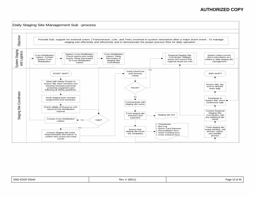
AUTHORIZED COPY
EMG-EDGF-00044 Rev. 4 (08/11) Page 10 of 45
Daily Staging Site Management Sub -process
Stag
ing S
ite C
oordi
nator
Syste
m St
aging
an
d Log
istics
Objec
tive
Provide S&L support for external crews (Transmission, Line , and Tree ) involved in system restoration after a major storm event . To manage staging site efficiently and effectively and to demonstrate the proper process flow for daily operation .
Meet with Safety Proctor to ensure S&L team members are
wearing necessary personal protective equipment and
following all Safety guidelines
END SHIFTSTART SHIFT
Verify staging team member assignments and schedules
Check validity of Resource Link reports (Crew Mobilization
reports)
Valid?Contact Crew Mobilization Liaison
Contact Staging Site Hotel Representative and caterer to confirm bed counts and meal
counts
No
Yes
Verify Fleet/Fuel and Security
needs
Needs?
Communicate with staging site owner
Track staging site inventory and
expenses
Ensure that staging site forms
are completed
≅ Timesheets≅ Bus Log≅ Storm Card Expense≅ Reconciliation form≅ Hotel Tracking form≅ Crew Check-in form
Staging site tool
No
Track staging site rental vehicles, cell
phones, radios, and satellite
phones
Contact Regional Staging Site
Coordinator with any additional site
needs
Participate in System S&L storm conference calls
Ensure S&L site area is cleaned
twice daily
Yes
Regional Staging Site Coordinator: Mitigate
issues and ensure that regional needs are met
System relays current storm information as it
relates to daily staging site management
Crew Mobilization Liaison: Relay information to Staging Site Coordinator
System Crew Mobilization: Check reports and rectify issues. Relay information
to Crew Mobilization Liaison
Crew Mobilization Liaison: Contact
System Crew Mobilization
AUTHORIZED COPY
EMG-EDGF-00044 Rev. 4 (08/11) Page 11 of 45
Job Descriptions SL1: System S&L Coordinator
Job Function
The System S&L Coordinator (SL1) manages all S&L job functions, ensuring all S&L field needs are met for both on system and off system storm response.
Job Description Manage S&L Timeline Checklist Participate in all Operational Calls, System Storm Calls, S&L Calls Negotiate number of staging sites to be opened with Distribution Storm Center Coordinator (DSSC1) and Regional
Storm Managers (REG1) Receive staging site request and notify System S&L of which sites will be activated Notify S&L Resource Managers to deploy S&L teams
Key Interface Points
Distribution System Storm Coordinator (DSSC1) Region Storm Managers (REG1) Resource Mobilization (RM1) Support Services (SS1) (SS2) S&L Regional Coordinator (SL6) Staging Site Coordinators (SL7) System Administration (SL1A) S&L Resource Management (SL2) System Site Coordinator (SL3) S&L Crew Mobilization Liaison (SL4) Hotel Fulfillment Lead (SL5)
Checklist of Actions This timeline is designed for a major hurricane entering our area. Smaller events would require timing of some activities to be adjusted. A near miss could require timing adjustments on some activities and cancellation of others. PRE-STORM SEASON Direct completion of all annual preparatory activities by S&L Process Owners:
Annual Staging Site Maintenance & Acquisition Process – System Site Coordinator Annual S&L Org Chart Review & Update – S&L Resource Manager Update Op Center Contact List and Catering List – S&L Op Center Liaison Participate in Distribution System Storm Drill – All Update Hotel List – Hotel Fulfillment Lead Complete Storm Org Certificate – S&L Resource Manager Update DSSOP – System Administration Update training modules and ensure S&L member completion of annual training and site team meetings –
System Administration BEFORE MAJOR STORM 5 Days (120 HRS) Prior to the Storm Make contact and coordinate with Resource Mobilization (RM1) when opening storm center and ensure S&L Crew
Mobilization Liaison (SL4) is included in all Resource Mobilization storm calls Monitor current weather reports Participate on Operational Calls and System Storm calls
AUTHORIZED COPY
EMG-EDGF-00044 Rev. 4 (08/11) Page 12 of 45
Establish communications with key storm personnel in Support Services such as: Fleet (FL2), Materials (SC3), Fuel (FL3), Rental Cars (FL5), Security (SEC1), Purchasing (SS3) etc…
Notify System S&L members and S&L Regional Coordinators (SL6) that company is on storm watch and to begin preparation for possible deployment
Notify System Site Coordinator(s) (SL3) to verify that potential staging sites in projected path of storm are available Contact System Storm Card Administrator (BO11) to ensure activation of appropriate storm plan credit card (Hotel
card needed asap for reservations). 4 Days (96 HRS) Prior to the Storm Negotiate number and location of Staging Sites to open on Operational call Establish communications with Support Services (SS) and other vendors as appropriate (This may be direct when
Support Services (SS) has no agreement with vendor) 3 Days (72 HRS) Prior to the Storm Notify System S&L members and S&L Regional Coordinators (SL6) that company is on storm alert and to prepare
for possible deployment 2 Days (48 HRS) Prior to the Storm Open System S&L Center to coincide with opening of System Storm Center Ensure all S&L Kits are ready for deployment Approve order request for Satellite Phone 1 Day (24 HRS) Prior to the Storm Make adjustment with internal and external storm response organizations based on latest crew mobilization plans. Confirm initial staging sites to be opened after all clear DURING MAJOR STORM Participate in all Operational and System Storm Calls Oversee all S&L Storm Calls Communicate System Level site and resource needs from Operational Calls to S&L Resource Management (SL2),
System Site Coordinator (SL3), Crew Mobilization Liaison (SL4), and Hotel Fulfillment Lead (SL5) Ensure co-location of S&L Sites with Distribution and Transmission personnel where possible Direct hotel procurement and cancellation activities through Hotel Fulfillment Lead (SL5) Direct System Site Coordinator to procure all additional materials and vendors needed through Support Services
to support activated Staging Sites Maintain communications with:
Distribution System Storm Coordinator (DSSC1) Regional Storm Managers (REG1) Resource Mobilization (RM1) Support Services (SS) All System S&L Positions
AFTER MAJOR STORM Ensure Lessons Learned are captured and reported back to DSSC Direct Hotel Fulfillment Lead (SL5) to ensure room cancellations are adequately processed to minimize
unnecessary costs Direct System Administration (SL1A) and S&L Financial Analyst (SL8) to ensure all S&L costs are reconciled and
submitted to Storm Accounting Direct System Site Coordinator (SL3) to ensure all Staging Sites are decommissioned and all materials and
supplies are picked up by vendors
AUTHORIZED COPY
EMG-EDGF-00044 Rev. 4 (08/11) Page 13 of 45
SL1A: System Administration A & B Job Function
System Administration (SL1A) is responsible for all administrative duties assigned by the System S&L Coordinator (SL1).
Job Description
System Administration A This position will: Participate in all S&L storm conference calls and publish meeting notes Distribute Storm Charging Information to System S&L Oversee submission of time and storm card estimates from System Administration B to S&L Financial Analyst
(SL8) Assist with S&L System Storm Room set-up Schedule all S&L conference calls and meetings Assist System S&L Coordinator (SL1), S&L Resource Management (SL2), System Site Coordinator (SL3), S&L
Crew Mobilization Liaison (SL4), S&L Financial Analyst (SL8) as needed Provide task direction to Operations Center Liaisons (SL3A) and S&L IT&T Liaison (SL3B) Collect and track S&L Lessons Learned at system level
System Administration B This position will: Participate in all S&L storm conference calls Provide S&L time estimates and storm cost estimates to S&L Financial Analyst (SL8) Assist with S&L System Storm Room set-up Assist S&L Financial Analyst (SL8), as needed Collect S&L Lessons Learned throughout storm restoration efforts Input and process all EIT Storm Time Entry Process all S&L Storm Card Transactions through Concur System daily
Key Interface Points System S&L Coordinator (SL1) S&L Resource Management (SL2) System Site Coordinator (SL3) S&L Crew Mobilization Liaison (SL4) Operations Center Liaison (SL3A) S&L IT&T Liaisons (SL3B) S&L Financial Analyst (SL8) Storm Accounting (BO7)
Checklist of Actions
PRE-STORM SEASON
Project Manage all annual preparatory activities by S&L Process Owners:
Begin Annual Staging Site Maintenance & Acquisition Process – System Site Coordinator Annual S&L Org Chart Review & Update – S&L Resource Manager Update Op Center Contact List and Catering List – S&L Op Center Liaison Participate in Distribution System Storm Drill – All Update Hotel List – Hotel Fulfillment Lead Complete Storm Org Certificate – S&L Resource Manager
AUTHORIZED COPY
EMG-EDGF-00044 Rev. 4 (08/11) Page 14 of 45
Update DSSOP – System Administration Update training modules and ensure S&L member completion of annual training and site team meetings –
System Administration BEFORE MAJOR STORM 5-4 Days (120-96 HRS) Prior to Storm
Schedule all S&L conference calls and meetings Initiate and establish communications with:
o Operation Center Liaison (SL3A) o S&L IT&T Liaisons (SL3B) o S&L Financial Analyst (SL8)
3-1 Days (72-24 HRS) Prior to Storm
Participate in all System S&L storm conference calls and publish meeting notes Assist with set-up of System S&L Storm Room DURING MAJOR STORM
Participate in all System S&L storm conference calls and publish meeting notes Distribute Storm Charging Information to System S&L Provide S&L time estimates and cost estimates to Financial Analyst (BO7) Assist S&L Resource Management (SL2), System Site Coordinator (SL3), & System S&L Coordinator (SL1),
S&L Crew Mobilization Liaison (SL4), as needed Provide task direction to Operations Center Liaisons (SL3A) and S&L IT&T Liaison (SL3B) Maintain communications with:
Operations Center Liaison (SL3A) S&L IT&T Liaison (SL3B) System S&L Coordinator (SL1) S&L Resource Management (SL2) System Site Coordinator (SL3) Crew Mobilization Liaison (SL4) Financial Analyst (BO7)
AFTER MAJOR STORM Assist with S&L System Storm Room break-down Begin Storm Card Reconciliation process Assist S&L Resource Management (SL2), System Site Coordinator (SL3), & System S&L Coordinator (SL1),
S&L Crew Mobilization Liaison (SL4), as needed
Tools and Information Needed DSSOP S&L Contact List Resource Link Tool S&L Mustering & Staging Site maps RSVP Tool Wall charts of staging sites and assigned personnel Corporate Time Entry for every EIT org supporting S&L S&L Site Timesheet S&L Kit Inventory Lists Major Storm Card Expense Reconciliation form Cash Advance Reconciliation form DEF S&L Site Tracking Tool (Financial Tracking Tool)
Training Requirements Training and directions received from System S&L Coordinator (SL1)
AUTHORIZED COPY
EMG-EDGF-00044 Rev. 4 (08/11) Page 15 of 45
SL2: S&L Resource Management Job Function S&L Resource Management (SL2) acts as the single point of contact to primarily address assigning personnel to the positions that best utilize their skill sets during storm restoration activities. Peacetime responsibility is imperative. Job Description This position will: Administer process to recruit and deploy resources by matching skill sets to S&L roles and responsibilities Develop the annual organizational chart, review and receive input from the System S&L Coordinator (SL1) Ensure that all S&L resources have reviewed their storm roles, collect/track written confirmation of their
understanding, and provide System S&L Coordinator (SL1) with list of confirmations Provide current personnel list for specific job training to S&L System Administration A (SL1A) Responsible for recruiting in peacetime for S&L members from current DEF personnel, i.e. Plants as well as
company retirees Monitor department organizational chart to ensure all new employees and new employee positions are assigned a
storm assignment Maintain employee roles within the RSVP tool Partner with System Site Coordinator (SL3) to determine S&L resources needed to manage a particular site Acquire/track/access need for S&L prior to and during storm restoration Identify available resources to open requested staging sites as requested by the System S&L Coordinator (SL1) Maintain S&L contact list and org chart Maintain and monitor RSVP tool during storm for the purposes of tracking teams and team movement Provide & post daily update of staging site locations and statistics to the storm website Key Interfaces: System S&L Coordinator DEF/DEC (SL1) Plants - FL Regional Site Coordinators (SL6) RSVP Coordinator (RM5) Retiree’s Organizations -FL (newsletter, luncheon, meetings) Guidant Check List of Actions
PRE-STORM SEASON
Participate in RSVP pre-season “refresher” training Pull updated S&L resource list from RSVP Assign any new resources to S&L Org Chart Update S&L Org Chart, S&L Contact List, and S&L Distribution lists with new resources Update the Family Preparedness Document Ensure employee and contractor contact information is updated in PeopleSoft and RSVP Tool BEFORE MAJOR STORM
4 Days (96 HRS) Prior to Storm
Develop resource plan based on level of storm expected Advise Staging Site Coordinators (SL7) to verify availability of team members Report to System S&L Coordinator (SL1) availability to open # of sites 3 Days (72 HRS) Prior to Storm
Adjust resources based on potential number and location of sites
AUTHORIZED COPY
EMG-EDGF-00044 Rev. 4 (08/11) Page 16 of 45
2 Days (48 HRS) Prior to Storm
Adjust resources based on potential number and location of sites 1 Days (24 HRS) Prior to Storm
Re-adjust resource plan upon receipt of gaps in availability DURING MAJOR STORM Enter site statistical data into tracking tool Confirm resources available due to potential damage Request supplemental teams as necessary Secure additional resources as appropriate On-going communication to determine needs Modify and update resource plan AFTER MAJOR STORM Reassign S&L members in RSVP to pre-storm S&L assignments Provide Lessons Learned to System Administration (SL1A) Methods of performing job duties Website, Voice, fax, E-mail, and face-to-face communications Participating in System S&L calls RSVP Tool Attending retiree luncheon, inserting notices in retiree newsletters and by phone Measures of success Staff all open Staging Sites with minimum of 15 team members and 0 position gaps Documents/forms needed to perform functions Mustering & Staging Site maps Wall Charts of Staging Sites and personnel assigned Site Resource Request (Excel) via Email/FAX (see attached) RSVP Tool
AUTHORIZED COPY
EMG-EDGF-00044 Rev. 4 (08/11) Page 17 of 45
SL3: System Site Coordinator Job Function The System Site Coordinator (SL3) is the primary contact for S&L Regional Coordinators (SL6) and Transmission to address S&L Site concerns while implementing best practices at sites throughout the system during storm restoration activities. Job Description Participate on all S&L conference calls Oversee execution of all S&L Site processes and identify any gaps; address gaps Coordinate with Transmission S&L to determine co-location opportunities Collaborate with Distribution and Regional Coordinators to calculate S&L Site capacities for maximum personnel
and equipment at activated sites Track lessons learned to identify S&L process improvement opportunities through field visits to activated S&L Sites Key Interfaces System S&L Coordinator (SL1) S&L Regional Coordinator (SL6) Staging Site Coordinator (SL7) System Administration (SL1A) Transmission S&L System Security Liaison (SEC1) Support Services (SS) Check List of Actions PRE-STORM SEASON Initiate and establish communications with Regional Utilization Coordinator (RUC’s), S&L Regional Coordinators
(SL6) and CIG representative to coordinate mapping of potential new S&L Sites Collect S&L Site information from RUC’s and update Team Lead Manual:
o HHA o Site Maps o Site Survey Rating o S&L Site Contact information
Develop and post S&L Site Map information on S&L Storm Page Develop and post S&L Site Roles and Responsibilities on S&L Storm Page Coordinate with Transmission S&L to update co-habitation S&L Site information in Team Lead Manual:
o Crew capacities o Parking o Support
BEFORE MAJOR STORM 4 Days (96 HRS) Prior to Storm
Initiate and establish communications with:
o System S&L Coordinator (SL1) o S&L Regional Coordinators (SL6) o System Security Liaison (SEC1) o Staging Site Coordinators (SL7) o Transmission S&L o Support Services (SS)
AUTHORIZED COPY
EMG-EDGF-00044 Rev. 4 (08/11) Page 18 of 45
3 Days (72 HRS) Prior to Storm
Initiate and establish communications with Support Services (Rental Cars) (FL5) to secure S&L Site rental
vehicles (15 passenger van’s Assorted pick-up trucks, mini-vans, and/or car’s) Initiate and establish communications with Purchasing (SS3). Submit Staging Site Request Form for each
requested staging site listing purchasing and material needs for site mobilization (including 32’ RV or Mobile Command Center)
Submit Staging Site Security Request Form for each requested staging site Request Mobile Command Center through Heavy Hauling (Include Link Here) Monitor site resource allocation to ensure site capacity is not exceeded and consult with Crew Mobilization
Liaison as needed Participate in pre-storm S&L Storm conference calls
2 Days (48 HRS) Prior to Storm
Monitor resource allocation/commitments for S&L Site selection Maintain communications with Purchasing (SS3) for additional needs or changes Initiate contact with S&L IT&T Liaisons (SL3B) for S&L Site information dispatch to assigned Staging Site
Coordinators (SL7) o Populate “Flash-Drive” with Team Lead and S&L Site information
Participate in pre-storm S&L Storm conference calls 1 Days (24 HRS) Prior to Storm
Collect current S&L Site information, populate and post Storm S&L Site Tracking form in “Current Storm
Information” link on Storm Page o Crew Count o S&L Site Assignment o Contact Information
Participate in pre-storm S&L Storm conference calls DURING MAJOR STORM Monitor site resource allocation to ensure site capacity is not exceeded and consult with Crew Mobilization Liaison
(SL4) as needed Benchmark and implement best practices Track lessons learned to identify S&L process improvement opportunities through field visits to activated S&L Sites Ensure co-location of S&L Sites with Distribution and Transmission personnel Maintain communications with S&L Regional Coordinators (SL6) Maintain communications with Transmission S&L Maintain communications with Support Services (SS) Represent System S&L Site Management on System S&L storm calls AFTER MAJOR STORM Oversee closing of all S&L Sites by coordinating with S&L Regional Coordinators (SL6) and Staging Site
Coordinators (SL7) Identify gaps in S&L System Storm Center processes for Lessons Learned report Recalculate S&L Site capacities for maximum personnel and equipment for new and existing S&L Sites Ensure S&L Sites have been completely closed or turned over to designated System partners Methods of performing job duties Voice and E-mail communications Participating in System S&L Storm Calls Conducting S&L Site visits as needed
AUTHORIZED COPY
EMG-EDGF-00044 Rev. 4 (08/11) Page 19 of 45
Measures of success No safety related incidents Best practices implemented real time across all S&L Sites Capitalize on 100% of opportunities to site co-locate with Transmission where applicable Documents/forms needed to perform functions S&L Roles & Responsibilities S&L Team rosters Transmission Team rosters S&L Mustering & Staging Site maps Staging and Logistics site information and contact list Resource Link Reports Email/ Post Spread Sheets/Budget Forecast Tool Staging Site Request Form Security Request Form Termination of Security Form Rental Vehicle Tracking Form Primary support location where employee works from: System Storm Center Training Requirements Job shadow experienced System Site Coordinator (SL3) for a period of one active storm season
AUTHORIZED COPY
EMG-EDGF-00044 Rev. 4 (08/11) Page 20 of 45
SL3A: Operation Center Liaison
Job Function
The Operation Center Liaisons (SL3A) are responsible for supporting the Operation Centers on a system-wide basis with initial catering set up needs in the event that there is severe damage in the area and local caterers are not able to respond or if they will be serving at least 50 people. The Operation Center Liaisons support this effort conjunction with S&L Regional Coordinators (SL6) and Support Services (SS).
Job Description
Provide Support Services (SS) with a comprehensive listing of local caterers, restaurants, and vendors Provide the following information about caterers, restaurants, and vendors: Contact Information History of previous storm support Ranking of vendor preferences
o Are they equipped to provide service if power is unavailable? o Are they able to provide breakfast, lunch, and dinner? o Distance and/or travel time to Operation Centers o Food quality and cleanliness of equipment and staff o Reliability of service during past storm seasons(if available)
Provide standardized tracking catering form to Op Center Contacts and consolidate feedback to update Catering List
Collaborate with Support Services (SS) to ensure contact has been established with new vendors, sample menus are acquired, negotiations are started, and contracts are secured for Operations Centers
Once catering services have been established for Operations Centers, the Operations Center Liaison will report to System Administration (SL1A) for further duties
Key Interface Points
System S&L Coordinator (SL1) System Site Coordinator (SL3) S&L Regional Coordinators (SL6) Staging Site Coordinators (SL7) System Administration (SL1A) Support (SS) Operations Center Contacts
Checklist of Actions
PRE-STORM SEASON Obtain name and contact information to include e-mail boxes (if applicable) of Key Interface Points Send out communication to Op Center contacts to update the preferred caterer’s list and hotel list Update preferred caterer’s list and hotel list Send preferred caterer’s list to Support Services (SS2&3) to ensure contact has been established with new
vendors Send hotel list to Hotel Fulfillment Lead (SL5) BEFORE MAJOR STORM 4 Days (96 HRS) Prior to Storm Establish communication with assigned Operations Center contacts 3-2 Days (72-48 HRS) Prior to Storm Assist in set up of System S& Storm Room Prepare families and homes for potential deployment
AUTHORIZED COPY
EMG-EDGF-00044 Rev. 4 (08/11) Page 21 of 45
1 Days (24 HRS) Prior to Storm Assist in set up of System S& Storm Room Prepare families and homes for potential deployment DURING MAJOR STORM Contact Operations Centers to establish/determine catering needs in the event that there is severe damage in the
area and local caterers are not able to respond or if they will be serving at least 50 people Arrange for all System Storm Room meals Support System Administration (SL1A) AFTER MAJOR STORM Reconcile storm card statements and receipts Support System Administration (SL1A)
Tools and Information Needed
Operation Center Questionnaire Operation Center Contact List Preferred Catering Contact List Local Hotel List Sample Communications
Training Requirements
Training and direction received from System Administration (SL1A)
AUTHORIZED COPY
EMG-EDGF-00044 Rev. 4 (08/11) Page 22 of 45
SL3B: S&L IT&T Liaisons
Job Function
The S&L IT&T Liaisons (SL3B) are responsible for providing 24 hour IT&T support and phone coverage in the System S&L Storm Room. They also provide administrative support to the System Site Coordinators (SL3), S&L Resource Management (SL2), Crew Mobilization Liaison (SL4) and System Administration (SL1A).
Job Description
24/7 coverage of System Staging & Logistics Phone lines Provide administrative support to the System Site Coordinators (SL3), S&L Resource Management (SL2), Crew
Mobilization Liaison (SL4) and System Administration (SL1A) Set up System S&L Storm Room Provide 24/7 IT&T support for S&L Regional Coordinators (SL6) and Staging Site Coordinators (SL7) Coordinate S&L IT&T kit inventory and restocking process with IT&T Manage S&L Air Card inventory and restocking process Manage S&L laptop inventory and distribution Key Interface Points
System Site Coordinators (SL3) S&L Resource Management (SL2) Crew Mobilization Liaison (SL4) System Administration (SL1A) S&L Regional Coordinator (SL6) System S&L Coordinator (SL1)
Checklist of Actions
PRE-STORM SEASON
Ensure all necessary software is loaded on all S&L laptops Activate S&L storm mailboxes BEFORE MAJOR STORM 3-2 Days (72-48 HRS) Prior to Storm Set up System S&L Storm Room Distribute field laptops, air cards, and Team Lead Manual on USB Secure External Drive Place order (per direction from System S&L Coordinator (SL1), inventory, and distribute for satellite phones DURING MAJOR STORM 24/7 coverage of System Staging & Logistics Phone lines Provide administrative support to the System Site Coordinators (SL3), S&L Resource Management (SL2), Crew
Mobilization Liaison (SL4) and System Administration (SL1A)
After Major Storm
AFTER MAJOR STORM Break Down System S&L Storm Room Collect field laptops and aircards Collect satellite phones Collect S&L IT&T laptops, satellite phones, USB flash drives; inventory, and re-stock Ensure IT&T Kits are retuned per IT&T process

AUTHORIZED COPY
EMG-EDGF-00044 Rev. 4 (08/11) Page 23 of 45
Tools and Information Needed
Phone PC/Laptop Fax Printer Copier
Training Requirements
All training and direction provided by System Site Coordinators (SL3) and System Administration (SL1A)
AUTHORIZED COPY
EMG-EDGF-00044 Rev. 4 (08/11) Page 24 of 45
SL4: Crew Mobilization Liaison Job Function The Crew Mobilization Liaison (SL4) is S&L’s sole point of contact with System Resource Management (RM1). Additionally, this position is the point person for any staging site issues that arise with regard to crew mobilization. Job Description This position will: Interface with System Resource Management (RM1) Ensure the timely flow of crew movement information Monitor the update process of the Resource Link Tool Represent crew mobilization on S&L team calls Provide Hotel Fulfillment Lead (SL5) with the number of people arriving at each staging/mustering site via
Resource Link Tool Provide staging sites with estimate of meals needed and truck counts via Resource Link Tool Key Interfaces System Mobilization - Line (RM3) System Mobilization – Tree ( RM4) System Resource Mobilization (RM1) System S&L Coordinator (SL1) System Site Coordinator (SL3) Hotel Fulfillment Lead (SL5) S&L Regional Coordinators (SL6) Staging Site Coordinators (SL7) System RSVP Coordinator (RM5) System Administration (SL1A) Checklist of Actions
PRE-STORM SEASON
Ensure new S&L sites acquired are added to Resource Link Tool Attend Resource Link Refresher Training BEFORE MAJOR STORM 4 Days (96 HRS) Prior to Storm
Initiate and establish communications with System Resource Management (RM1), Initiate and establish communications with Hotel Fulfillment Lead (SL5) and Fulfillment Team (SL5B) Participate in pre-storm System S&L conference calls 3 Days (72 HRS) Prior to Storm
Participate in pre-storm System S&L conference calls Participate in pre-storm Resource Mobilization conference calls Monitor Resource Link for early crew projections 2 Days (48 HRS) Prior to Storm
Participate in pre-storm System S&L conference calls Participate in pre-storm Resource Mobilization conference calls Monitor Resource Link for early crew projections
AUTHORIZED COPY
EMG-EDGF-00044 Rev. 4 (08/11) Page 25 of 45
1 Day (24 HRS) Prior to Storm
Participate in pre-storm System S&L conference calls Participate in pre-storm Resource Mobilization conference calls Monitor Resource Link for early crew projections DURING MAJOR STORM Closely monitor crew mobilization activity Obtain early estimates of crew movement throughout the restoration process Ensure the timely flow of crew movement information Monitor the update process of the Resource Link Tool Interface with System Resource Management (RM1), Hotel Fulfillment Lead (SL5), S&L Regional Coordinators
(SL6) and Staging Site Coordinators (SL7) Represent crew mobilization on S&L team calls Methods of performing job duties Voice and E-mail communications Participating in System S&L Storm calls Measures of success Timely flow of crew mobilization information to S&L teams Documents/forms needed Resource Link Tool Crew Rosters S&L site information and contact list Staging and Mustering site maps Primary support location where employee works System S&L Storm Room
AUTHORIZED COPY
EMG-EDGF-00044 Rev. 4 (08/11) Page 26 of 45
SL5: Hotel Fulfillment Lead Job Function
The Hotel Fulfillment Lead (SL5) directs all activity for the Fulfillment Team (SL5B) and Acquisition Team (SL5A1A). The primary responsibility of the Hotel Fulfillment Lead (SL5) is to meet bed needs and inform the System S&L Coordinator (SL1) when beds are not available and the need for alternative housing exists while satisfying daily financial targets. Job Description
Direct all activity for the Fulfillment Team (SL5B) Direct and monitor hotel procurement and cancellation numbers daily Work closely with Crew Mobilization Liaison (SL4) to establish daily bed needs for crews Maintain daily buffer of needed beds Work closely with S&L Financial Analyst (SL8) to establish and meet daily financial targets Participate in System S&L storm conference calls Coordinate need for overflow with Transmission Collaborate and maintain communication with Acquisition Lead to ensure daily needs are met
Key Interface Points
System S&L Coordinator (SL1) Fulfillment Team (SL5B) Crew Mobilization Liaison (SL4) Acquisition Lead (SL5A) Acquisition Coordinator (SL5A1) Acquisition Team (SL5A1A) Staging Site Hotel Rep (SL7C) S&L Financial Analyst (SL8) Checklist of Actions PRE-STORM SEASON
Participate in Annual Storm Drill Facilitate annual Hotel Workshop to maintain Hotel Lists by Staging Site/Operation Centers, and City BEFORE MAJOR STORM Develop bed fulfillment plan based on expected level of storm Report bed availability based on staging site to System S&L Coordinator (SL1) Twenty-four hours prior to storm, make adjustments with internal and external storm response organizations
based on latest S&L Resource Management plans DURING MAJOR STORM Direct all activity for the Fulfillment Team (SL5B) Direct and monitor hotel procurement and cancellation numbers daily Work closely with Crew Mobilization Liaison (SL4) to establish daily bed needs for crews Maintain daily buffer of needed beds Work closely with S&L Financial Analyst (SL8) to establish and meet daily financial targets Participate in System S&L storm conference calls Coordinate need for overflow with Transmission Maintain communication with Staging Site Hotel Reps (SL7C)
AUTHORIZED COPY
EMG-EDGF-00044 Rev. 4 (08/11) Page 27 of 45
AFTER MAJOR STORM Ensure room cancellations are adequately processed to minimize unnecessary costs
Tools and Information Needed
Florida State, Regional, and Storm Tracking maps Reports from Crew Mobilization Liaison (SL4) via Resource Link tool S&L mustering and staging site maps Storm Web page, voice, fax, e-mail, and face-to-face communications System S&L storm conference calls Hotel Tool
Engaged in the Following Sub-process:
Hotel Procurement
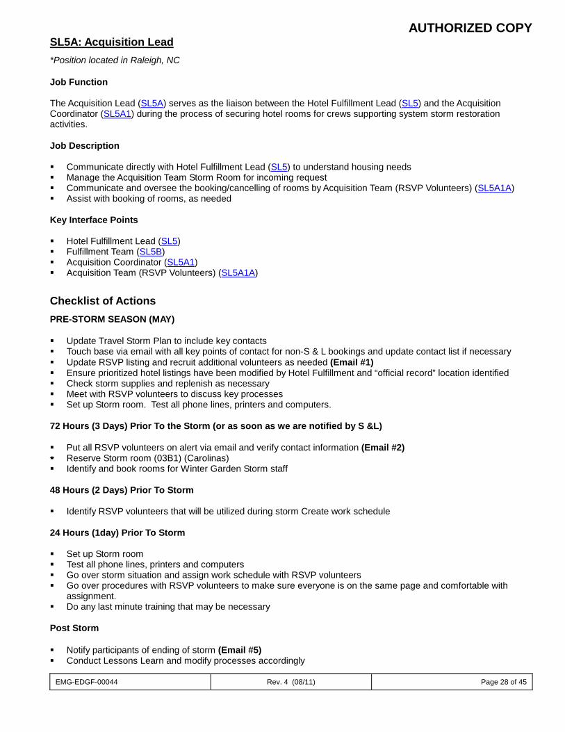
AUTHORIZED COPY
EMG-EDGF-00044 Rev. 4 (08/11) Page 28 of 45
SL5A: Acquisition Lead *Position located in Raleigh, NC Job Function The Acquisition Lead (SL5A) serves as the liaison between the Hotel Fulfillment Lead (SL5) and the Acquisition Coordinator (SL5A1) during the process of securing hotel rooms for crews supporting system storm restoration activities. Job Description Communicate directly with Hotel Fulfillment Lead (SL5) to understand housing needs Manage the Acquisition Team Storm Room for incoming request Communicate and oversee the booking/cancelling of rooms by Acquisition Team (RSVP Volunteers) (SL5A1A) Assist with booking of rooms, as needed Key Interface Points Hotel Fulfillment Lead (SL5) Fulfillment Team (SL5B) Acquisition Coordinator (SL5A1) Acquisition Team (RSVP Volunteers) (SL5A1A)
Checklist of Actions PRE-STORM SEASON (MAY) Update Travel Storm Plan to include key contacts Touch base via email with all key points of contact for non-S & L bookings and update contact list if necessary Update RSVP listing and recruit additional volunteers as needed (Email #1) Ensure prioritized hotel listings have been modified by Hotel Fulfillment and “official record” location identified Check storm supplies and replenish as necessary Meet with RSVP volunteers to discuss key processes Set up Storm room. Test all phone lines, printers and computers. 72 Hours (3 Days) Prior To the Storm (or as soon as we are notified by S &L) Put all RSVP volunteers on alert via email and verify contact information (Email #2) Reserve Storm room (03B1) (Carolinas) Identify and book rooms for Winter Garden Storm staff 48 Hours (2 Days) Prior To Storm Identify RSVP volunteers that will be utilized during storm Create work schedule 24 Hours (1day) Prior To Storm Set up Storm room Test all phone lines, printers and computers Go over storm situation and assign work schedule with RSVP volunteers Go over procedures with RSVP volunteers to make sure everyone is on the same page and comfortable with
assignment. Do any last minute training that may be necessary
Post Storm Notify participants of ending of storm (Email #5) Conduct Lessons Learn and modify processes accordingly
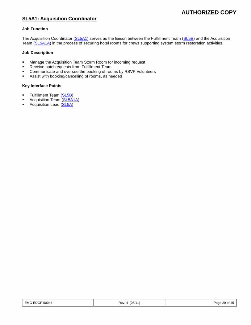
AUTHORIZED COPY
EMG-EDGF-00044 Rev. 4 (08/11) Page 29 of 45
SL5A1: Acquisition Coordinator Job Function The Acquisition Coordinator (SL5A1) serves as the liaison between the Fulfillment Team (SL5B) and the Acquisition Team (SL5A1A) in the process of securing hotel rooms for crews supporting system storm restoration activities. Job Description Manage the Acquisition Team Storm Room for incoming request Receive hotel requests from Fulfillment Team Communicate and oversee the booking of rooms by RSVP Volunteers Assist with booking/cancelling of rooms, as needed Key Interface Points Fulfillment Team (SL5B) Acquisition Team (SL5A1A) Acquisition Lead (SL5A)
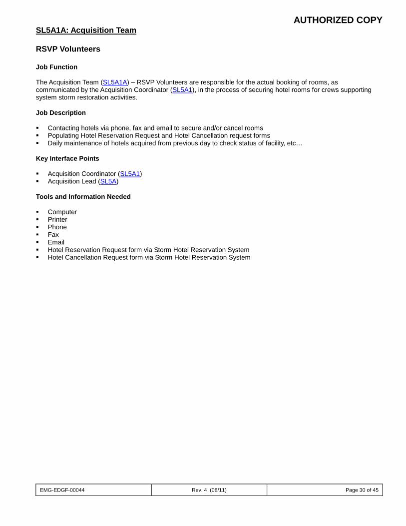
AUTHORIZED COPY
EMG-EDGF-00044 Rev. 4 (08/11) Page 30 of 45
SL5A1A: Acquisition Team RSVP Volunteers Job Function The Acquisition Team (SL5A1A) – RSVP Volunteers are responsible for the actual booking of rooms, as communicated by the Acquisition Coordinator (SL5A1), in the process of securing hotel rooms for crews supporting system storm restoration activities. Job Description Contacting hotels via phone, fax and email to secure and/or cancel rooms Populating Hotel Reservation Request and Hotel Cancellation request forms Daily maintenance of hotels acquired from previous day to check status of facility, etc…
Key Interface Points Acquisition Coordinator (SL5A1) Acquisition Lead (SL5A) Tools and Information Needed Computer Printer Phone Fax Email Hotel Reservation Request form via Storm Hotel Reservation System Hotel Cancellation Request form via Storm Hotel Reservation System
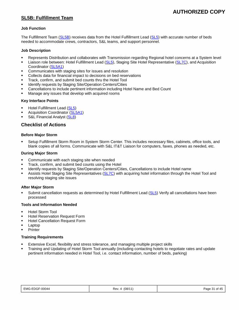
AUTHORIZED COPY
EMG-EDGF-00044 Rev. 4 (08/11) Page 31 of 45
SL5B: Fulfillment Team
Job Function
The Fulfillment Team (SL5B) receives data from the Hotel Fulfillment Lead (SL5) with accurate number of beds needed to accommodate crews, contractors, S&L teams, and support personnel.
Job Description
Represents Distribution and collaborates with Transmission regarding Regional hotel concerns at a System level Liaison role between: Hotel Fulfillment Lead (SL5), Staging Site Hotel Representative (SL7C), and Acquisition
Coordinator (SL5A1) Communicates with staging sites for issues and resolution Collects data for financial impact to decisions on bed reservations Track, confirm, and submit bed counts thru the Hotel Tool Identify requests by Staging Site/Operation Centers/Cities Cancellations to include pertinent information including Hotel Name and Bed Count Manage any issues that develop with acquired rooms
Key Interface Points
Hotel Fulfillment Lead (SL5) Acquisition Coordinator (SL5A1) S&L Financial Analyst (SL8)
Checklist of Actions
Before Major Storm
Setup Fulfillment Storm Room in System Storm Center. This includes necessary files, cabinets, office tools, and blank copies of all forms. Communicate with S&L IT&T Liaison for computers, faxes, phones as needed, etc.
During Major Storm
Communicate with each staging site when needed Track, confirm, and submit bed counts using the Hotel Identify requests by Staging Site/Operation Centers/Cities, Cancellations to include Hotel name Assists Hotel Staging Site Representatives (SL7C) with acquiring hotel information through the Hotel Tool and
resolving staging site issues
After Major Storm Submit cancellation requests as determined by Hotel Fulfillment Lead (SL5) Verify all cancellations have been
processed
Tools and Information Needed
Hotel Storm Tool Hotel Reservation Request Form Hotel Cancellation Request Form Laptop Printer
Training Requirements
Extensive Excel, flexibility and stress tolerance, and managing multiple project skills Training and Updating of Hotel Storm Tool annually (including contacting hotels to negotiate rates and update
pertinent information needed in Hotel Tool, i.e. contact information, number of beds, parking)
AUTHORIZED COPY
EMG-EDGF-00044 Rev. 4 (08/11) Page 32 of 45
SL6: S&L Regional Coordinator Job Function The S&L Regional Coordinator (SL6) is the single point of contact to RSM’s (REG1), and RRC’s (REG5), with the primary function of addressing Regional S&L Site concerns during storm restoration activities. The S&L Regional Coordinator (SL6) also acts as a liaison between the Staging Site Coordinators (SL7) and the System Site Coordinators (SL3) to communicate S&L Site needs. Job Description Management sponsor to mitigate issues and ensure Regional needs are being met Provide leadership and support to the Staging Site Coordinators (SL7) with human resource and other escalated
issues Proactively identify potential issues within the region to mitigate future problems and communicate them
appropriately Interface and support the RSM’s (REG1), RRC’s (REG5) and System Site Coordinator (SL3) as needed Actively participate in the Regional and System S&L calls Communicate Regional staging needs to the System Site Coordinator (SL3)
Key Interfaces Regional Storm Manager (REG1) Regional Resource Coordinator (REG5) Operation Center Coordinator (OPS1) System S&L Coordinator (SL1) Staging Site Coordinators (SL7) S&L Resource Management (SL2) System Site Coordinator (SL3) Checklist of Actions
PRE-STORM SEASON
Participate in System S&L/S&L Regional Coordinator Meeting to review staging site information (HHA, site ratings, site maps, etc)
Coordinate meeting with RRC (REG5) to review existing site information (HHAs, site ratings, site maps, etc) and develop list of new/alternative S&L staging sites
Conduct site visits for all newly identified and modified S&L staging sites; communicate any site modifications to System Site Coordinator (SL3)
Participate in system storm drill; identify lessons learned and enhancements; support regional storm season preparation as needed.
BEFORE MAJOR STORM 4 Days (96 HRS) Prior to Storm Initiate and establish communications with RSM’s (REG1), RRC’s (REG5), and S&L Resource Management
(SL2) Work with RRC’s (REG5) to confirm availability and identify any site limitations for each S&L site Establish communications with Staging Site Coordinators (SL7) assigned by S&L Resource Management
(SL2) Participate in pre-storm System S&L Storm conference calls
3-2 Days (72-48 HRS) Prior to Storm Establish communications with Staging Site Coordinators (SL7) assigned by S&L Resource Management
(SL2) Convey information needed for Staging Site Coordinator (SL7) to contact Regional/Operations personnel;
begin planning process for setting up staging sites
AUTHORIZED COPY
EMG-EDGF-00044 Rev. 4 (08/11) Page 33 of 45
Participate in pre-storm System S&L Storm conference calls Become familiar with and set up of storm mail boxes Ensure staging sites activated have been notified
Days (24 HRS) Prior to Storm Participate in pre-storm System S&L Storm conference calls Ensure pre-storm measures have been taken to protect/prepare family and home Finalize plans for staging areas – Monitor Staging Site Coordinators (SL7) and Staging Site Teams as they
prepare for setting up activated staging areas immediately after the storm has passed
DURING MAJOR STORM
Mitigate regional S&L issues and ensure regional needs are being met Log and track all regional S&L issues; provide after storm to support lessons learned Interface and support RSM’s (REG1), RRC’s (REG5), and System Site Coordinator (SL3) Communicate Regional staging needs to the System Site Coordinator (SL3) AFTER MAJOR STORM Assist in closing of S&L Site by collaborating with all System personnel Oversee closing of all S&L Sites by coordinating with Staging Site Coordinators (SL7) Identify gaps in S&L System Storm Center processes for Lessons Learned report Ensure S&L Sites have been completely closed or turned over to designated System partners
Methods of performing job duties Voice and E-mail communications Participating in Regional and System S&L calls Field visits to Regional S&L Sites Measures of success No safety related incidents Resolution of Regional escalated calls with the expectation of 0 being escalated to System S&L 0 Human Resource issues escalated to System S&L 0 Site customer issues escalated to System S&L Accuracy of Regional Site counts, i.e. beds, food, etc. Documents/forms needed Regional Operations Contact List System S&L & Supporting Org Contact List S&L Roles & Responsibilities S&L Team Rosters Regional S&L Mustering & Staging Site Maps Resource Link Reports Timeline Checklist Primary support location where employee works Regional Storm Center Regional S&L Sites Regional Operations Centers Training Requirements Job shadow experienced S&L Regional Coordinator (SL6) for a period of one active storm season
AUTHORIZED COPY
EMG-EDGF-00044 Rev. 4 (08/11) Page 34 of 45
SL7: Staging Site Coordinator Job Function The Staging Site Coordinator (SL7) is responsible for setting up, managing, operating, & closing down the S&L Site. Team activities may be located in the Regional Office, Operations Center, Line and Service Centers, or in the field. The Staging Site Coordinator (SL7) works under the direction of S&L Regional Coordinators (SL6). Job Description Activate the team when directed by S&L Regional Coordinator (SL6) Interface with S&L Safety Coordinator (SAF3) and Site Safety Proctor (SL7D) Ensure all team members possess personal safety kits, containing proper safety items
Steel toe shoes Hard hats
Manage the set up and decommissioning of S&L Sites Manage all storm credit card transactions and records Track daily inventory and expenses to ensure accurate cost projections Manage all personnel resources Ensure team members have/bring vehicles needed for staging site Assign and track rental vehicles to team members Assign and track cells/radios and satellite phones used by team Request/obtain supplies needed to set-up/operate S&L Site Ensure materials needed for initial set-up of S&L Site are in-route Coordinate with on-site assigned site security (materials, equipment, personnel) Have daily contact with caterer to adjust meal counts and resolve issues Coordinate fuel procurement/fueling arrangements for staging site Oversee fuel needs/operations at site or delegate responsibility to team member Approve fuel invoices
Provide to Site Administrative Support (SL7B) Coordinate all needed vehicle maintenance and repairs with Support Services (Fleet) (FL2) Coordinate oil spill clean-up or mishaps at staging area
Environmental (DA/ENV1), Contact Fleet (FL2), Safety (SAF3) Organize materials at staging areas per S&L Site map Implement the staging area per plan and Region Needs Matrix (# of crews) Manage staging team member assignments and duty schedules Establish and maintain communications with:
S&L Regional Coordinator (SL6) Operations Center S&L Liaison (Provided by Operation Center)
Coordinate transfer of responsibilities back to Operating Center. i.e. Security, food, tents, hotels, drinks, ice, and parking
Close and clean staging site Key Interface Points System Site Coordinator (SL3) S&L Regional Coordinators (SL6) Staging Site Coordinator (SL7) S&L Resource Management (SL2) S&L Safety Coordinator (SAF3) Site Safety Proctor (SL7D) Support Services (Supply Chain ) (SS) Crew Mobilization Liaison (SL4) Hotel Fulfillment Lead (SL5) Site Hotel Representative (SL7C) Regional Environmental Lead (DA/ENV1)
AUTHORIZED COPY
EMG-EDGF-00044 Rev. 4 (08/11) Page 35 of 45
Checklist of Actions PRE-STORM SEASON Complete Annual Staging Site Coordinator Training Complete Annual Staging Site Team Meetings Update contact information for all team members Inventory PPE needed for Staging Site Team (to be acquired if activated for storm response) BEFORE MAJOR STORM 4 Days (96 HRS) Prior to Storm Initiate and establish communications with S&L Site team members at direction of S&L Resource Management
(SL2) (could be 96/72/48 hour dependent on storm track and speed) Participate in pre-storm System S&L Storm conference calls 3 Days (72 HRS) Prior to Storm Activate S&L Site Team when directed by S&L Regional Coordinator (SL6) and S&L Resource Management (SL2) Participate in pre-storm System S&L Storm conference calls 2 Days (48 HRS) Prior to Storm Make final preparations to secure your family and home Obtain USB Flash Drive from S&L IT&T Liaison (SL3B) with up-to-date Team Lead Manual download Obtain assigned S&L Site Map information and familiarize yourself with site layout Obtain all required S&L Site Kits (ITT Kit, S&L Office Supply Kit, S&L Site Storm Kits Inventory list) Obtain Storm Laptop Initiate and establish communications with S&L Staging Site contacts Participate in pre-storm System S&L Storm conference calls Purchase remaining PPE items needed for Staging Site Team members 1 Day (24 HRS) Prior to Storm Make final preparations to secure your family and home Participate in pre-storm System S&L Storm conference calls DURING MAJOR STORM Implement the assigned S&L Site area per S&L Site Map Ensure S&L team members report to S&L Site and bring Personal Storm Kits Initiate and establish communications with S&L Safety Coordinator (SAF3)and Site Safety Proctor (SL7D) Initiate and establish communications with on-site Security Liaison Maintain communications with S&L Regional Coordinator (SL6) and System Site Coordinator (SL3) Maintain communications with Site Hotel Representative (SL7C) to monitor hotel activity Manage S&L Site team member assignments Track daily S&L Site inventory and expenses Coordinate with S&L Site Caterer to establish meal counts Coordinate Fuel procurement Interface with Crew Mobilization Liaison (SL4) Obtain early estimates of crew movement throughout the restoration process Closely monitor crew mobilization activity Represent assigned S&L Site on S&L team calls AFTER MAJOR STORM Manage the decommission of S&L Site Reconcile all storm credit card transactions and records Reconcile daily inventory and expenses for accurate cost projections Reconcile all tracking records of rental vehicles used on S&L Site
AUTHORIZED COPY
EMG-EDGF-00044 Rev. 4 (08/11) Page 36 of 45
Reconcile all tracking records for cells/radios and satellite phones used by team Initiate S&L Site Security decommissioning with on-site security (materials, equipment, personnel) Terminate fuel procurement/fueling arrangements for staging site Reconcile fuel invoices from Site Administrative Support (SL7B) Coordinate communications with S&L Regional Coordinator (SL6) to ensure S&L Site decommission Coordinate transfer of responsibilities back to Operating Center. i.e. Security, food, tents, hotels, drinks, ice, and
parking Recalculate S&L Site capacities for maximum personnel and equipment for new and existing S&L Sites Close and clean staging site Ensure S&L Site has been completely closed and/or turned over to designated System partners Work in conjunction with RUC’s (REG5), S&L Regional Coordinators (SL6), and S&L System Site Coordinator
(SL3) to ensure staging site property owners are satisfied with site clean up Identify gaps in S&L Site processes for Lessons Learned report Methods of performing job duties Voice and E-mail communications Participating in System S&L Storm Calls Measures of success No safety related incidents Resolution of S&L Site customer conflict issues with the expectation of 0 being escalated to the S&L Regional
Coordinator (SL6) 0 Human Resource issues escalated to Regional S&L Validation of S&L Site counts, i.e. beds, food, etc. Documents/forms needed System S&L & Supporting Org Contact List S&L Roles & Responsibilities S&L Team Rosters S&L Mustering & Staging Site Maps Resource Link Reports Timeline Checklist Crew Check-in form S&L Site Timesheet Bus Log Cash Advance Reconciliation Report form Major Storm Card Expense Reconciliation form DEF S&L Site Tracking Tool S&L Hotel Tracking Tool Hotel Tracking Template S&L Mustering Site Rating form S&L Staging Site Rating form S&L Team Lead Kit sign-out form ITT Kit Inventory list Personal Storm Kit Inventory list S&L Office Supply Kit list S&L Site Storm Kits Inventory list
Kits A-E Primary support location where employee works S&L Mustering Sites S&L Staging Sites Operations Centers Training Requirements Must attend annual Staging Site Coordinator training
AUTHORIZED COPY
EMG-EDGF-00044 Rev. 4 (08/11) Page 37 of 45
SL7A: Site Support Job Function Site Support (SL7A) personnel work under the direction of the Staging Site Coordinator (SL7) and are responsible for setting up, maintaining, and closing down the S&L Site. Job Description Assist with S&L Site area set-up Support Materials Coordinator (SS) with organizing and maintaining materials on S&L Site
Procure materials, equipment, and supplies as needed or requested Assist with loading and/or unloading materials (if fork lift used, must be certified operator) Issue materials to crews as directed
Coordinate S&L Site parking and traffic direction on site. Provide morning and evening coverage (will require a lead person)
Assist with meal arrangements and/or deliveries as needed Maintain staging area in good order Replenish ice and water stocks in distribution areas Carry out other duties as assigned Assist in shut-down/clean-up and closing of staging area Key Interface Points Staging Site Coordinator (SL7) Materials Coordinator (SS) Site Safety Proctor (SL7D) Checklist of Actions PRE-STORM SEASON Update contact information in PeopleSoft Inventory PPE list and notify Staging Site Safety Proctor (SL7D) of needed items (during annual Team Meeting) Review Family/Home Preparedness plan Attend annual Team Meeting Complete annual storm organization certificate confirming knowledge and understanding of assigned storm role
(at direction of S&L Resource Management (SL2)) BEFORE MAJOR STORM 4 Days (96 HRS) Prior to Storm Ensure all PPE and storm gear is accounted for and ready Maintain communication with assigned Staging Site Coordinator (SL7) 3 Days (72 HRS) Prior to Storm Read/review weather updates provided to stay informed of latest track and potential impacts Make initial plans for securing family/home Maintain communication with assigned Staging Site Coordinator (SL7) 2 Days (48 HRS) Prior to Storm Check latest forecast track and potential impacts of storm to plan accordingly Make final preparations for securing family/home so last minute decisions do not have to be made Maintain communication with assigned Staging Site Coordinator (SL7) for any changes to plan Make sure vehicle to be used is fully fueled Ensure have cash and medications on hand for two weeks
AUTHORIZED COPY
EMG-EDGF-00044 Rev. 4 (08/11) Page 38 of 45
1 Days (24 HRS) Prior to Storm Continue monitoring storm’s path and intensity for family/home potential issues Final check for PPE and storm gear readiness Continue communicating with assigned Staging Site Coordinator for any updates/changes to plan or locations to
report so team can be deployed without delay Maintain communication with assigned Staging Site Coordinator (SL7) DURING MAJOR STORM Assist with S&L Site set-up according to S&L Site Map (if available) Assist Materials Coordinator (SS) in organizing and maintaining materials Assist with loading/unloading of materials (if fork lift used, must be certified operator)
Issue materials to crews as directed by Materials Coordinator (SS) Coordinate parking and traffic direction on site Coordinate fueling of trucks in designated S&L Site fueling area Deliver meals to crews as needed Replenish ice and water stocks in distribution areas Maintain staging area in good order AFTER MAJOR STORM Assist in shut-down, clean-up and closing of S&L Site
Training Requirements Training and direction received from Staging Site Coordinator (SL7) Review of orientation packet provided following RSVP enrollment
AUTHORIZED COPY
EMG-EDGF-00044 Rev. 4 (08/11) Page 39 of 45
SL7B: Site Administrative Support
Job Function
The Site Administrative Support (SL7B) is responsible for all administrative duties assigned by the Staging Site Coordinator (SL7)
Job Description Set-up S&L Site office at S&L Site Maintain and replenish office supplies for S&L Site office (before & after) Compile various S&L Site and tracking reports as needed
o Rental Vehicles o Cell phones, radios, and satellite phones o Timesheets for S&L Site members o Crew Check in sheets and Check Out/Survey sheets o Daily site material and procurements to staging site coordinator o Daily storm card and expenses charged reported to System Administration (SL1A)
Perform administrative duties to support S&L Team as assigned by Staging Site Coordinator (SL7)
Key Interface Points
Staging Site Coordinator (SL7) Site Hotel Representative (SL7C) Site Support (SL7A) Site Safety Proctor (SL7D) System Administration (SL1A) S&L Financial Analyst (SL8) Checklist of Actions
PRE-STORM SEASON
Continue monitoring storm’s path and intensity for family/home potential issues Final check for PPE and storm gear readiness Continue communicating with assigned Staging Site Coordinator for any updates/changes to plan or locations to
report so team can be deployed without delay Maintain communication with assigned Staging Site Coordinator (SL7) BEFORE MAJOR STORM 4 Days (96 HRS) Prior to Storm Review system storm plan along with Site Administrative Support responsibilities Check S&L Site Kits for all office supplies and prepare a list of items needed, if necessary Review Family Preparedness Plan 3 Days (72 HRS) Prior to Storm Ensure all PPE and storm gear is accounted for and ready Maintain communication with assigned Staging Site Coordinator (SL7) Prepare for possible deployment
2 Days (48 HRS) Prior to Storm Ensure storm credit cards, storm computers, and printers are available/working (based on location – if assigned
away from kit location, move to 96 or 72 hour checklist) Ensure the storm USB flashdrive is loaded with current team lead manual Maintain communication with assigned Staging Site Coordinator (SL7)
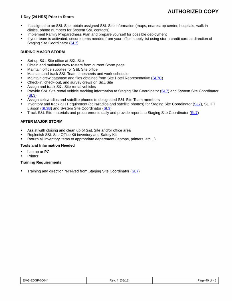
AUTHORIZED COPY
EMG-EDGF-00044 Rev. 4 (08/11) Page 40 of 45
1 Day (24 HRS) Prior to Storm If assigned to an S&L Site, obtain assigned S&L Site information (maps, nearest op center, hospitals, walk in
clinics, phone numbers for System S&L contacts) Implement Family Preparedness Plan and prepare yourself for possible deployment If your team is activated, secure items needed from your office supply list using storm credit card at direction of
Staging Site Coordinator (SL7)
DURING MAJOR STORM Set-up S&L Site office at S&L Site Obtain and maintain crew rosters from current Storm page Maintain office supplies for S&L Site office Maintain and track S&L Team timesheets and work schedule Maintain crew database and files obtained from Site Hotel Representative (SL7C) Check-in, check-out, and survey crews on S&L Site Assign and track S&L Site rental vehicles Provide S&L Site rental vehicle tracking information to Staging Site Coordinator (SL7) and System Site Coordinator
(SL3) Assign cells/radios and satellite phones to designated S&L Site Team members Inventory and track all IT equipment (cells/radios and satellite phones) for Staging Site Coordinator (SL7), SL ITT
Liaison (SL3B) and System Site Coordinator (SL3) Track S&L Site materials and procurements daily and provide reports to Staging Site Coordinator (SL7) AFTER MAJOR STORM Assist with closing and clean up of S&L Site and/or office area Replenish S&L Site Office Kit inventory and Safety Kit Return all inventory items to appropriate department (laptops, printers, etc…)
Tools and Information Needed Laptop or PC Printer
Training Requirements
Training and direction received from Staging Site Coordinator (SL7)
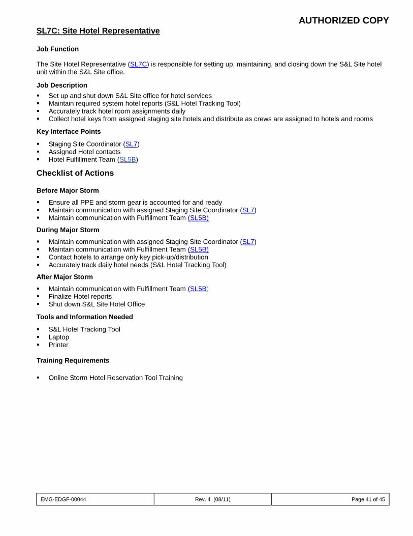
AUTHORIZED COPY
EMG-EDGF-00044 Rev. 4 (08/11) Page 41 of 45
SL7C: Site Hotel Representative
Job Function
The Site Hotel Representative (SL7C) is responsible for setting up, maintaining, and closing down the S&L Site hotel unit within the S&L Site office.
Job Description Set up and shut down S&L Site office for hotel services Maintain required system hotel reports (S&L Hotel Tracking Tool) Accurately track hotel room assignments daily Collect hotel keys from assigned staging site hotels and distribute as crews are assigned to hotels and rooms
Key Interface Points
Staging Site Coordinator (SL7) Assigned Hotel contacts Hotel Fulfillment Team (SL5B)
Checklist of Actions
Before Major Storm
Ensure all PPE and storm gear is accounted for and ready Maintain communication with assigned Staging Site Coordinator (SL7) Maintain communication with Fulfillment Team (SL5B)
During Major Storm
Maintain communication with assigned Staging Site Coordinator (SL7) Maintain communication with Fulfillment Team (SL5B) Contact hotels to arrange only key pick-up/distribution Accurately track daily hotel needs (S&L Hotel Tracking Tool)
After Major Storm
Maintain communication with Fulfillment Team (SL5B) Finalize Hotel reports Shut down S&L Site Hotel Office
Tools and Information Needed
S&L Hotel Tracking Tool Laptop Printer Training Requirements
Online Storm Hotel Reservation Tool Training
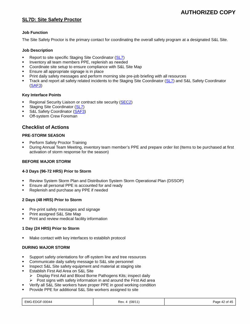
AUTHORIZED COPY
EMG-EDGF-00044 Rev. 4 (08/11) Page 42 of 45
SL7D: Site Safety Proctor Job Function
The Site Safety Proctor is the primary contact for coordinating the overall safety program at a designated S&L Site. Job Description
Report to site specific Staging Site Coordinator (SL7) Inventory all team members PPE, replenish as needed Coordinate site setup to ensure compliance with S&L Site Map Ensure all appropriate signage is in place Print daily safety messages and perform morning site pre-job briefing with all resources Track and report all safety related incidents to the Staging Site Coordinator (SL7) and S&L Safety Coordinator
(SAF3) Key Interface Points
Regional Security Liaison or contract site security (SEC2) Staging Site Coordinator (SL7) S&L Safety Coordinator (SAF3) Off-system Crew Foreman Checklist of Actions PRE-STORM SEASON
Perform Safety Proctor Training During Annual Team Meeting, inventory team member’s PPE and prepare order list (Items to be purchased at first
activation of storm response for the season) BEFORE MAJOR STORM 4-3 Days (96-72 HRS) Prior to Storm Review System Storm Plan and Distribution System Storm Operational Plan (DSSOP) Ensure all personal PPE is accounted for and ready Replenish and purchase any PPE if needed 2 Days (48 HRS) Prior to Storm Pre-print safety messages and signage Print assigned S&L Site Map Print and review medical facility information 1 Day (24 HRS) Prior to Storm Make contact with key interfaces to establish protocol DURING MAJOR STORM Support safety orientations for off-system line and tree resources Communicate daily safety message to S&L site personnel Inspect S&L Site safety equipment and material at staging site Establish First Aid Area on S&L Site
Display First Aid and Blood Borne Pathogens Kits; inspect daily Post signs with safety information in and around the First Aid area
Verify all S&L Site workers have proper PPE in good working condition Provide PPE for additional S&L Site workers assigned to site
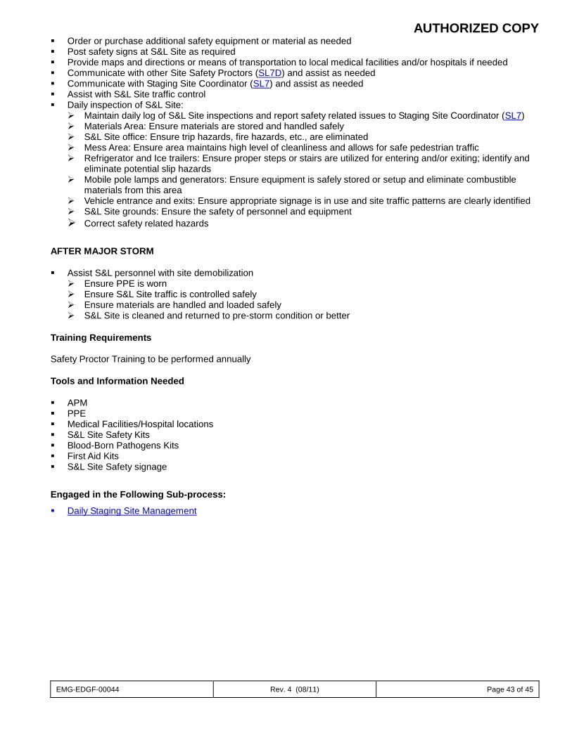
AUTHORIZED COPY
EMG-EDGF-00044 Rev. 4 (08/11) Page 43 of 45
Order or purchase additional safety equipment or material as needed Post safety signs at S&L Site as required Provide maps and directions or means of transportation to local medical facilities and/or hospitals if needed Communicate with other Site Safety Proctors (SL7D) and assist as needed Communicate with Staging Site Coordinator (SL7) and assist as needed Assist with S&L Site traffic control Daily inspection of S&L Site:
Maintain daily log of S&L Site inspections and report safety related issues to Staging Site Coordinator (SL7) Materials Area: Ensure materials are stored and handled safely S&L Site office: Ensure trip hazards, fire hazards, etc., are eliminated Mess Area: Ensure area maintains high level of cleanliness and allows for safe pedestrian traffic Refrigerator and Ice trailers: Ensure proper steps or stairs are utilized for entering and/or exiting; identify and
eliminate potential slip hazards Mobile pole lamps and generators: Ensure equipment is safely stored or setup and eliminate combustible
materials from this area Vehicle entrance and exits: Ensure appropriate signage is in use and site traffic patterns are clearly identified S&L Site grounds: Ensure the safety of personnel and equipment Correct safety related hazards
AFTER MAJOR STORM Assist S&L personnel with site demobilization
Ensure PPE is worn Ensure S&L Site traffic is controlled safely Ensure materials are handled and loaded safely S&L Site is cleaned and returned to pre-storm condition or better
Training Requirements Safety Proctor Training to be performed annually
Tools and Information Needed APM PPE Medical Facilities/Hospital locations S&L Site Safety Kits Blood-Born Pathogens Kits First Aid Kits S&L Site Safety signage
Engaged in the Following Sub-process:
Daily Staging Site Management
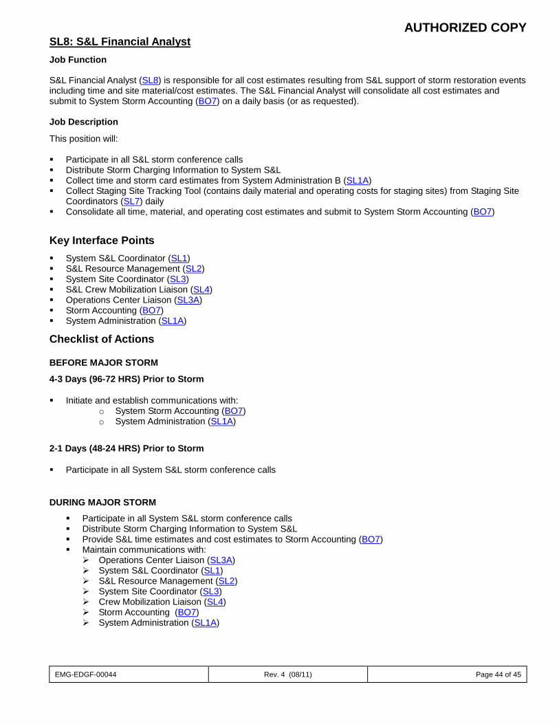
AUTHORIZED COPY
EMG-EDGF-00044 Rev. 4 (08/11) Page 44 of 45
SL8: S&L Financial Analyst Job Function
S&L Financial Analyst (SL8) is responsible for all cost estimates resulting from S&L support of storm restoration events including time and site material/cost estimates. The S&L Financial Analyst will consolidate all cost estimates and submit to System Storm Accounting (BO7) on a daily basis (or as requested).
Job Description
This position will: Participate in all S&L storm conference calls Distribute Storm Charging Information to System S&L Collect time and storm card estimates from System Administration B (SL1A) Collect Staging Site Tracking Tool (contains daily material and operating costs for staging sites) from Staging Site
Coordinators (SL7) daily Consolidate all time, material, and operating cost estimates and submit to System Storm Accounting (BO7)
Key Interface Points System S&L Coordinator (SL1) S&L Resource Management (SL2) System Site Coordinator (SL3) S&L Crew Mobilization Liaison (SL4) Operations Center Liaison (SL3A) Storm Accounting (BO7) System Administration (SL1A)
Checklist of Actions
BEFORE MAJOR STORM
4-3 Days (96-72 HRS) Prior to Storm Initiate and establish communications with:
o System Storm Accounting (BO7) o System Administration (SL1A)
2-1 Days (48-24 HRS) Prior to Storm Participate in all System S&L storm conference calls
DURING MAJOR STORM
Participate in all System S&L storm conference calls Distribute Storm Charging Information to System S&L Provide S&L time estimates and cost estimates to Storm Accounting (BO7) Maintain communications with:
Operations Center Liaison (SL3A) System S&L Coordinator (SL1) S&L Resource Management (SL2) System Site Coordinator (SL3) Crew Mobilization Liaison (SL4) Storm Accounting (BO7) System Administration (SL1A)
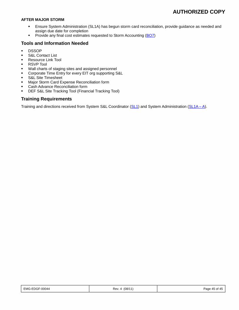
AUTHORIZED COPY
EMG-EDGF-00044 Rev. 4 (08/11) Page 45 of 45
AFTER MAJOR STORM
Ensure System Administration (SL1A) has begun storm card reconciliation, provide guidance as needed and assign due date for completion
Provide any final cost estimates requested to Storm Accounting (BO7)
Tools and Information Needed DSSOP S&L Contact List Resource Link Tool RSVP Tool Wall charts of staging sites and assigned personnel Corporate Time Entry for every EIT org supporting S&L S&L Site Timesheet Major Storm Card Expense Reconciliation form Cash Advance Reconciliation form DEF S&L Site Tracking Tool (Financial Tracking Tool)
Training Requirements Training and directions received from System S&L Coordinator (SL1) and System Administration (SL1A – A).
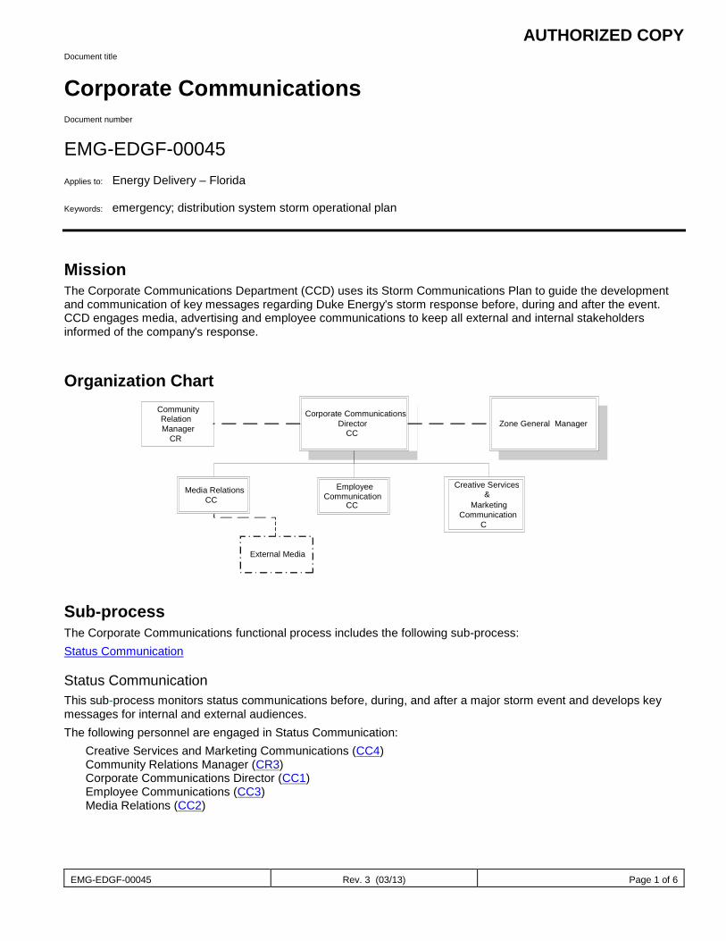
AUTHORIZED COPY
EMG-EDGF-00045 Rev. 3 (03/13) Page 1 of 6
Document title
Corporate Communications Document number
EMG-EDGF-00045 Applies to: Energy Delivery – Florida Keywords: emergency; distribution system storm operational plan
Mission The Corporate Communications Department (CCD) uses its Storm Communications Plan to guide the development and communication of key messages regarding Duke Energy's storm response before, during and after the event. CCD engages media, advertising and employee communications to keep all external and internal stakeholders informed of the company's response.
Organization Chart
Sub-process The Corporate Communications functional process includes the following sub-process: Status Communication
Status Communication This sub-process monitors status communications before, during, and after a major storm event and develops key messages for internal and external audiences. The following personnel are engaged in Status Communication:
Creative Services and Marketing Communications (CC4) Community Relations Manager (CR3) Corporate Communications Director (CC1) Employee Communications (CC3) Media Relations (CC2)
Corporate Communications Director
CC
Zone General Manager Community Relation Manager
CR
Employee Communication CC
Creative Services &
Marketing Communication
C
Media Relations CC
External Media
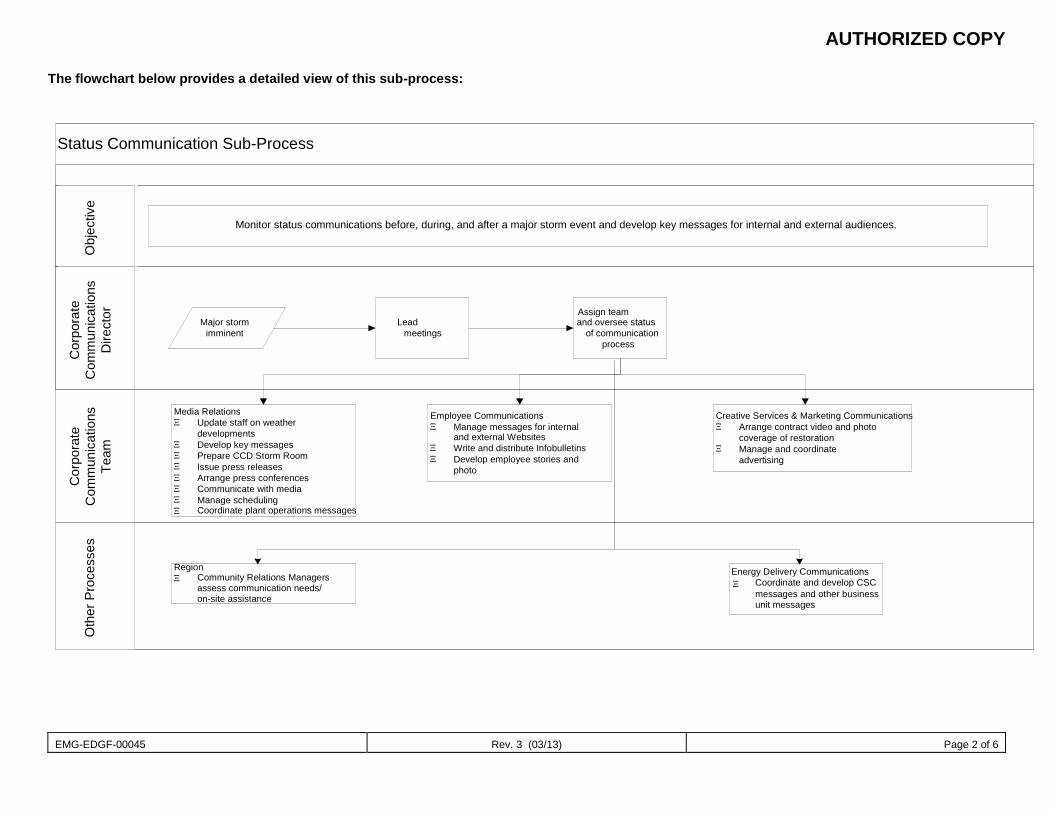
AUTHORIZED COPY
EMG-EDGF-00045 Rev. 3 (03/13) Page 2 of 6
The flowchart below provides a detailed view of this sub-process:
Status Communication Sub-Process
Monitor status communications before, during, and after a major storm event and develop key messages for internal and external audiences.
Major storm imminent
Lead meetings
Media Relations Ξ Update staff on weather
developments Ξ Develop key messages Ξ Prepare CCD Storm Room Ξ Issue press releases Ξ Arrange press conferences Ξ Communicate with media Ξ Manage scheduling
Employee Communications Ξ Manage messages for internal
and external Websites Ξ Write and distribute Infobulletins Ξ Develop employee stories and
photo
Creative Services & Marketing Communications Ξ Arrange contract video and photo
coverage of restoration Ξ Manage and coordinate
advertising
Assign team and oversee status
of communication process
Region Ξ Community Relations Managers
assess communication needs/ on-site assistance
Energy Delivery Communications Ξ Coordinate and develop CSC
messages and other business unit messages
Ξ Coordinate plant operations messages
Obj
ectiv
e C
orpo
rate
C
omm
unic
atio
ns
Dire
ctor
Cor
pora
te
Com
mun
icat
ions
Te
am
Oth
er P
roce
sses
AUTHORIZED COPY
EMG-EDGF-00045 Rev. 3 (03/13) Page 3 of 6
Job Descriptions
CC1: Corporate Communications Director Job Function The Corporate Communications Director is the primary contact for management and CCD staff before, during and after a storm. This individual addresses staffing issues, and key message oversight. Job Description
Create CCD Storm schedule, schedule section meetings and keep section updated on mandatory storm calls. Report to senior management when designated by CCD VP. Designate Lead Media Coordinator.
Key Interface Points
Executive team CCD VP CCD staff Zone General Managers External Relations – CRM (CR3)/CIG/CSC Distribution System Storm Coordinator (DSSC1)
CHECKLIST OF ACTIONS
Before Major Storm
Create CCD storm schedule
Attend all storm calls and update staff from the calls.
Oversee the development of storm preparation messages.
During Major Storm
Help media relations create and distribute key messages to media.
Attend all storm-related calls.
After Major Storm
Senior management liaison
Oversee Lead Media Communicator’s development of key messages during shift.
Oversee the development of storm restoration messages.
Tools and Information Needed Job related.
Training Requirements Job related.
CC2: Media Relations Job Function The media relations team members primarily serve as media liaisons communicating to customers and media before, during and after a storm. Additionally, the team’s responsibilities include updating regularly updating key internal and external audiences on storm preparation/restoration efforts.
AUTHORIZED COPY
EMG-EDGF-00045 Rev. 3 (03/13) Page 4 of 6
Key Contributors Lead Media Communicator Media Communicators Stakeholder Communicators Plant Communicator
Job Description
Lead Media Communicator (LMC) o Oversee public relations efforts (in cooperation with Corporate Communications Director). o Develop and distribute key messages and press releases. o Respond to media inquiries and provide regular outage updates. o Participate in all system storm conference calls. o Coordinate communications needs with Zone General Managers and External Relations. o Proactively pitch media and coordinate press access. o Act as the company spokesperson, or assign and schedule MC designee. o Develop and coordinate social media communications, as appropriate
Media Communicator (MC) o Develop and distribute key messages into press releases and other materials (in cooperation with
Lead Media Communicator). o Proactively pitch media and coordinate press access. o Respond to media inquiries and provide regular outage updates.
Identify the locations of Duke FL crews working in the field (upon request). o Act as a company spokesperson, as needed. o Answer the Duke Energy Florida media line. o Coordinate and update social media communications, as appropriate
Stakeholder Communicator (SC) o Gathers and updates information on Duke FL’s system-wide storm preparation/restoration efforts (in
cooperation with all Media Communicators). o Compiles and provides the daily Duke FL morning briefing. o Compiles and provides the Governor’s briefing at regular intervals or as significant events occur. o Compiles and provides the EOC briefing at regular intervals or as significant events occur. o Assist Media Communicators, as needed.
Plant Communicator (PC) o Serve as the media liaison for power plants before, during and after storms. o Participate in all System Storm calls. o Respond to media inquiries on plant-related storm procedures. o If a plant is affected by a storm, regularly update CCD and key stakeholders with plant status and
other pertinent information. o If no plant is affected by a storm, assist in the execution of other CCD storm duties.
Key Interface Points
CCD VP Zone GM’s External Relations External media Duke FL management Governor’s office EOC Plant management
AUTHORIZED COPY
EMG-EDGF-00045 Rev. 3 (03/13) Page 5 of 6
CHECKLIST OF ACTIONS Before Major Storm
Participate in all system storm conference calls. (LMC) Develop and distribute key messages and press releases. (LMC/MC) Ensure storm communications room contains adequate supplies. (ALL) Coordinate Duke FL CCD employee travel. (ALL)
During Major Storm
Continue to communicate to the media. (LMC/MC/PC)
After Major Storm
Coordinate communications needs with Zone GM’s and External Relations. (LMC) Communicate with internal management, Governor’s office and EOC (SC) Develop and distribute key messages and press releases. (LMC/MC/PC) Proactive media pitching and coordinate press access. (LMC/MC/PC) Possible media field duty. (ALL)
Tools and Information Needed Job related.
Training Requirements Job related.
CC3: Employee Communications Job Function This position will typically be under the supervision of the Manager – Employee Communications, North Carolina. To effectively communicate with Duke Energy employees before, during and after a storm affects PE service territory. Job Description
Activation and management of Storm Center web site. (Carolina team) Distribution of InfoBulletins and RSVP InfoBulletins (Carolina team, with content from Florida) Ensuring arrangements of photographs and first-person accounts of employee contributions to the restoration
efforts. Key Interface Points
Distribution System Storm Coordinator (DSSC1) Director, Florida Communications Manager, Employee Communications
CHECKLIST OF ACTIONS
Before Major Storm
Activation and management of Storm Center web site. Distribution of InfoBulletins and RSVP InfoBulletins Ensuring arrangements of photographs and first-person accounts of employee contributions to the restoration
efforts.
During Major Storm
Management of Storm Center web site. Distribution of InfoBulletins and RSVP InfoBulletins
AUTHORIZED COPY
EMG-EDGF-00045 Rev. 3 (03/13) Page 6 of 6
After Major Storm
Management of Storm Center web site. Distribution of InfoBulletins and RSVP InfoBulletins Ensuring arrangements of photographs and first-person accounts of employee contributions to the restoration
efforts.
Tools and Information Needed N/A
Training Requirements Job related.
CC4: Creative Services & Marketing Communications Job Function This position will typically be under the direction of the Manager – Creative Services & Marketing Communications, North Carolina. Oversee the advertising process before, during and after a storm. Job Description
Advance and continuing advertising schedules Graphics and collateral communication illustrating restoration procedures. Vehicle signage, banners and news conference signage.
Key Interface Points
CCD VP Director, Florida Communications Zone GM’s and CRMS
CHECKLIST OF ACTIONS
Before Major Storm
Advance advertising schedules. Graphics and collateral communication illustrating restoration procedures.
During Major Storm
Graphics and collateral communication illustrating restoration procedure.
After Major Storm
Continuing advertising schedules Graphics and collateral communication illustrating restoration procedures. Vehicle signage, banners and news conference signage.
Tools and Information Needed N/A
Training Requirements Job related. Additional Information Should the Duke Energy Florida Corporate Communications Department require additional assistance before, during or after a major storm, North Carolina-based Corporate Communications Department representatives may provide supplemental resources and support. In addition to this plan, Duke Energy Florida’s Corporate Communications Department operates under the guidelines set forth in the department’s more comprehensive, annually updated storm communications plan.
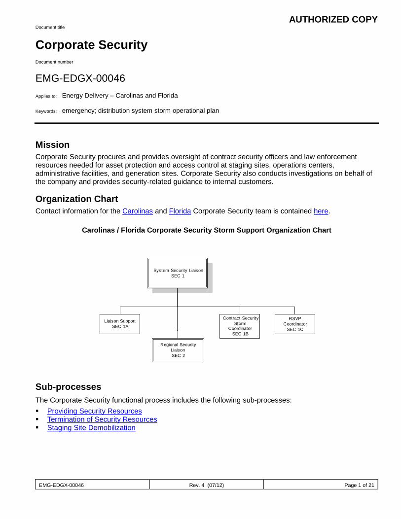
AUTHORIZED COPY
EMG-EDGX-00046 Rev. 4 (07/12) Page 1 of 21
Document title
Corporate Security Document number
EMG-EDGX-00046 Applies to: Energy Delivery – Carolinas and Florida Keywords: emergency; distribution system storm operational plan
Mission Corporate Security procures and provides oversight of contract security officers and law enforcement resources needed for asset protection and access control at staging sites, operations centers, administrative facilities, and generation sites. Corporate Security also conducts investigations on behalf of the company and provides security-related guidance to internal customers.
Organization Chart Contact information for the Carolinas and Florida Corporate Security team is contained here.
Carolinas / Florida Corporate Security Storm Support Organization Chart
Sub-processes The Corporate Security functional process includes the following sub-processes: Providing Security Resources Termination of Security Resources Staging Site Demobilization
System Security LiaisonSEC 1
Regional SecurityLiaisonSEC 2
Contract SecurityStorm
CoordinatorSEC 1B
Liaison SupportSEC 1A
RSVPCoordinator
SEC 1C
AUTHORIZED COPY
EMG-EDGX-00046 Rev. 4 (07/12) Page 2 of 21
Providing Security Resources These sub-processes provide guidance to company personnel on how to communicate a request for security coverage or terminate security coverage during storm response operations. The following personnel are engaged in Providing Security Resources: System Security Liaison (SEC1) Regional Security Liaison (SEC2) Contract Security Storm Coordinator (SEC1B) System Staging and Logistics Coordinator (SL1)
The flowcharts below provide a detailed view of these sub-processes:
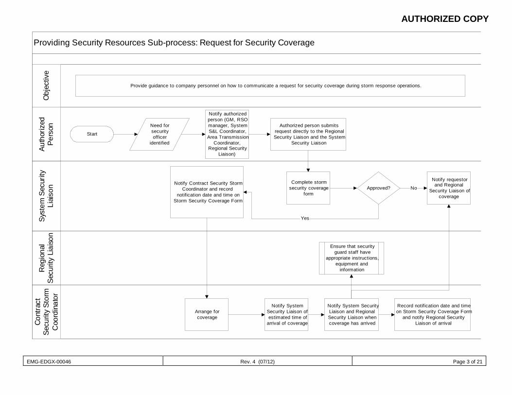
AUTHORIZED COPY
EMG-EDGX-00046 Rev. 4 (07/12) Page 3 of 21
Providing Security Resources Sub-process: Request for Security CoverageAu
thor
ized
Pers
onSy
stem
Sec
urity
Liai
son
Reg
iona
lSe
curit
y Li
aiso
n
Cont
ract
Secu
rity
Stor
mC
oord
inat
orO
bjec
tive
Provide guidance to company personnel on how to communicate a request for security coverage during storm response operations.
Start
Need forsecurityofficer
identified
Notify authorizedperson (GM, RSOmanager, SystemS&L Coordinator,
Area TransmissionCoordinator,
Regional SecurityLiaison)
Authorized person submitsrequest directly to the RegionalSecurity Liaison and the System
Security Liaison
Complete stormsecurity coverage
formApproved?
Notify requestorand Regional
Security Liaison ofcoverage
Notify Contract Security StormCoordinator and record
notification date and time onStorm Security Coverage Form
Arrange forcoverage
Notify SystemSecurity Liaison ofestimated time of
arrival of coverage
Notify System SecurityLiaison and RegionalSecurity Liaison whencoverage has arrived
No
Yes
Ensure that securityguard staff have
appropriate instructions,equipment and
information
Record notification date and timeon Storm Security Coverage Form
and notify Regional SecurityLiaison of arrival
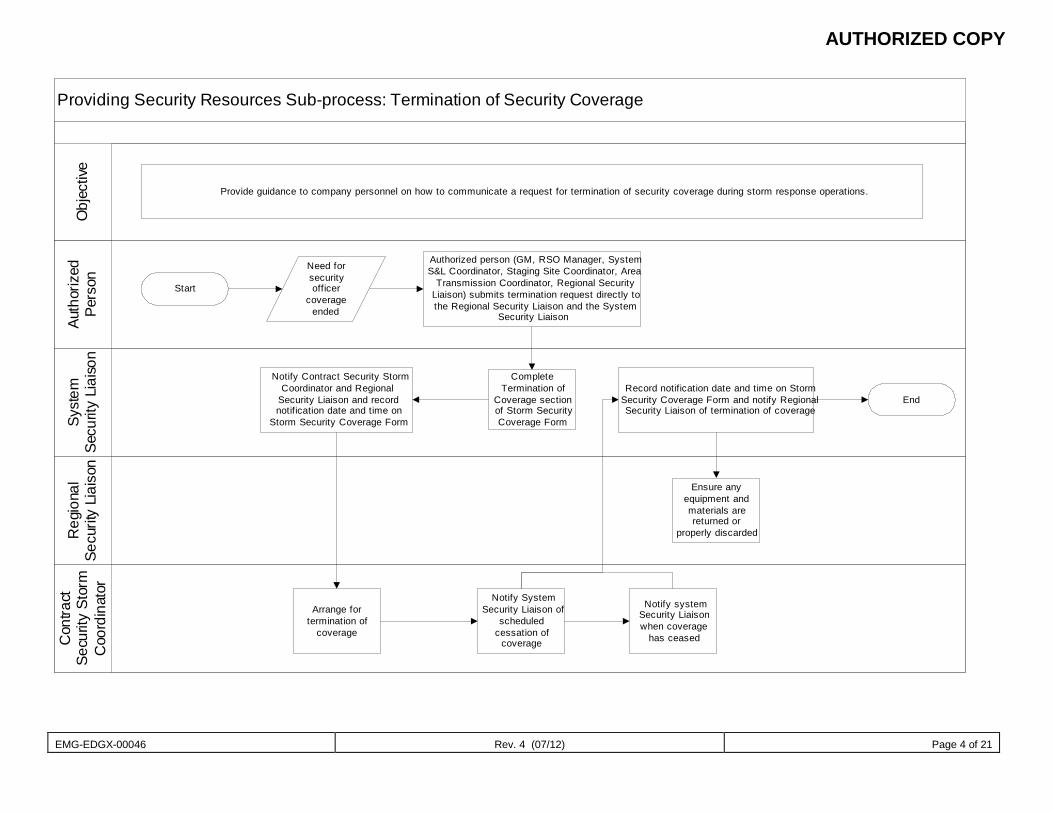
AUTHORIZED COPY
EMG-EDGX-00046 Rev. 4 (07/12) Page 4 of 21
Providing Security Resources Sub-process: Termination of Security CoverageAu
thor
ized
Pers
onSy
stem
Secu
rity
Liai
son
Reg
iona
lSe
curit
y Li
aiso
n
Con
tract
Secu
ri ty
Stor
mC
oord
inat
orO
bjec
tive
Provide guidance to company personnel on how to communicate a request for termination of security coverage during storm response operations.
Start
Need forsecurityofficer
coverageended
Authorized person (GM, RSO Manager, SystemS&L Coordinator, Staging Site Coordinator, Area
Transmission Coordinator, Regional SecurityLiaison) submits termination request directly tothe Regional Security Liaison and the System
Security Liaison
CompleteTermination of
Coverage sectionof Storm SecurityCoverage Form
Notify Contract Security StormCoordinator and Regional
Security Liaison and recordnotification date and time on
Storm Security Coverage Form
Arrange fortermination of
coverage
Ensure anyequipment andmaterials arereturned or
properly discarded
Notify SystemSecurity Liaison of
scheduledcessation of
coverage
Notify systemSecurity Liaisonwhen coverage
has ceased
Record notification date and time on StormSecurity Coverage Form and notify RegionalSecurity Liaison of termination of coverage
End
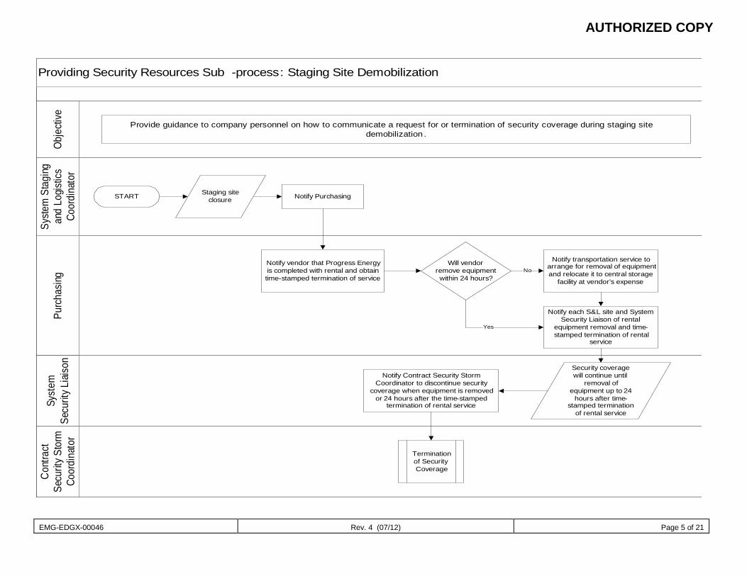
AUTHORIZED COPY
EMG-EDGX-00046 Rev. 4 (07/12) Page 5 of 21
Providing Security Resources Sub -process: Staging Site Demobilization
Syste
m S
tagi
ng
and
Logis
tics
Coor
dina
tor
Purc
hasin
gSy
stem
Se
curit
y Liai
son
Cont
ract
Se
curit
y Sto
rm
Coor
dina
tor
Obje
ctive
Provide guidance to company personnel on how to communicate a request for or termination of security coverage during staging site demobilization .
START Notify PurchasingStaging site closure
Notify vendor that Progress Energy is completed with rental and obtain time-stamped termination of service
Will vendor remove equipment within 24 hours?
Notify transportation service to arrange for removal of equipment and relocate it to central storage
facility at vendor’s expense
No
Notify each S&L site and System Security Liaison of rental
equipment removal and time-stamped termination of rental
service
Yes
Notify Contract Security Storm Coordinator to discontinue security
coverage when equipment is removed or 24 hours after the time-stamped
termination of rental service
Security coverage will continue until
removal of equipment up to 24
hours after time-stamped termination
of rental service
Termination of Security Coverage
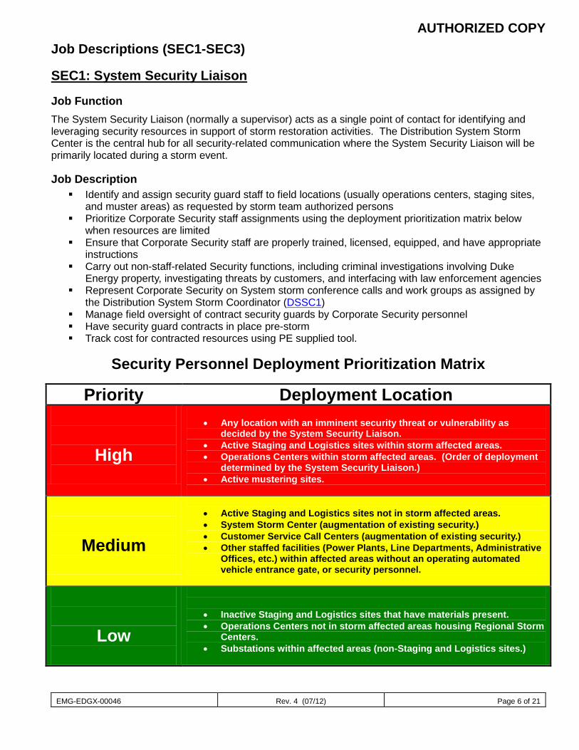
AUTHORIZED COPY
EMG-EDGX-00046 Rev. 4 (07/12) Page 6 of 21
Job Descriptions (SEC1-SEC3)
SEC1: System Security Liaison
Job Function The System Security Liaison (normally a supervisor) acts as a single point of contact for identifying and leveraging security resources in support of storm restoration activities. The Distribution System Storm Center is the central hub for all security-related communication where the System Security Liaison will be primarily located during a storm event.
Job Description Identify and assign security guard staff to field locations (usually operations centers, staging sites,
and muster areas) as requested by storm team authorized persons Prioritize Corporate Security staff assignments using the deployment prioritization matrix below
when resources are limited Ensure that Corporate Security staff are properly trained, licensed, equipped, and have appropriate
instructions Carry out non-staff-related Security functions, including criminal investigations involving Duke
Energy property, investigating threats by customers, and interfacing with law enforcement agencies Represent Corporate Security on System storm conference calls and work groups as assigned by
the Distribution System Storm Coordinator (DSSC1) Manage field oversight of contract security guards by Corporate Security personnel Have security guard contracts in place pre-storm Track cost for contracted resources using PE supplied tool.
Security Personnel Deployment Prioritization Matrix
Priority Deployment Location
High
• Any location with an imminent security threat or vulnerability as
decided by the System Security Liaison. • Active Staging and Logistics sites within storm affected areas. • Operations Centers within storm affected areas. (Order of deployment
determined by the System Security Liaison.) • Active mustering sites.
Medium
• Active Staging and Logistics sites not in storm affected areas. • System Storm Center (augmentation of existing security.) • Customer Service Call Centers (augmentation of existing security.) • Other staffed facilities (Power Plants, Line Departments, Administrative
Offices, etc.) within affected areas without an operating automated vehicle entrance gate, or security personnel.
Low
• Inactive Staging and Logistics sites that have materials present. • Operations Centers not in storm affected areas housing Regional Storm
Centers. • Substations within affected areas (non-Staging and Logistics sites.)
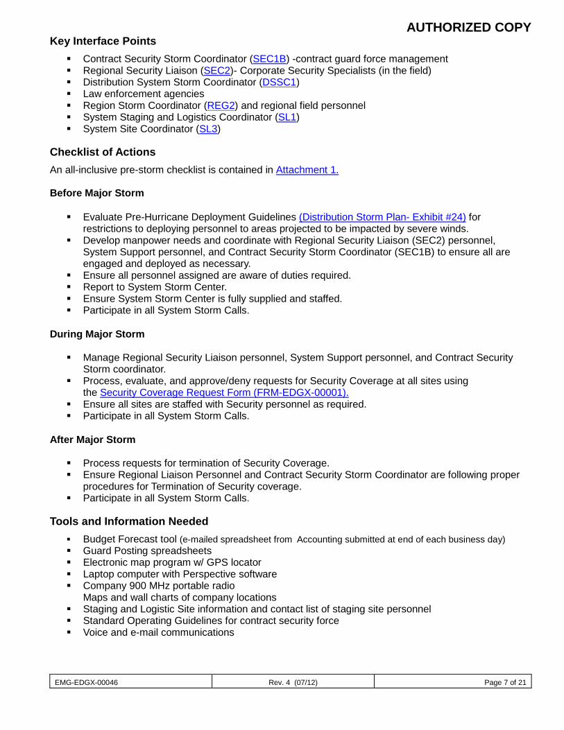
AUTHORIZED COPY
EMG-EDGX-00046 Rev. 4 (07/12) Page 7 of 21
Key Interface Points Contract Security Storm Coordinator (SEC1B) -contract guard force management Regional Security Liaison (SEC2)- Corporate Security Specialists (in the field) Distribution System Storm Coordinator (DSSC1) Law enforcement agencies Region Storm Coordinator (REG2) and regional field personnel System Staging and Logistics Coordinator (SL1) System Site Coordinator (SL3)
Checklist of Actions An all-inclusive pre-storm checklist is contained in Attachment 1. Before Major Storm Evaluate Pre-Hurricane Deployment Guidelines (Distribution Storm Plan- Exhibit #24) for
restrictions to deploying personnel to areas projected to be impacted by severe winds. Develop manpower needs and coordinate with Regional Security Liaison (SEC2) personnel,
System Support personnel, and Contract Security Storm Coordinator (SEC1B) to ensure all are engaged and deployed as necessary.
Ensure all personnel assigned are aware of duties required. Report to System Storm Center. Ensure System Storm Center is fully supplied and staffed. Participate in all System Storm Calls.
During Major Storm Manage Regional Security Liaison personnel, System Support personnel, and Contract Security
Storm coordinator. Process, evaluate, and approve/deny requests for Security Coverage at all sites using
the Security Coverage Request Form (FRM-EDGX-00001). Ensure all sites are staffed with Security personnel as required. Participate in all System Storm Calls.
After Major Storm Process requests for termination of Security Coverage. Ensure Regional Liaison Personnel and Contract Security Storm Coordinator are following proper
procedures for Termination of Security coverage. Participate in all System Storm Calls.
Tools and Information Needed Budget Forecast tool (e-mailed spreadsheet from Accounting submitted at end of each business day) Guard Posting spreadsheets Electronic map program w/ GPS locator Laptop computer with Perspective software Company 900 MHz portable radio
Maps and wall charts of company locations Staging and Logistic Site information and contact list of staging site personnel Standard Operating Guidelines for contract security force Voice and e-mail communications
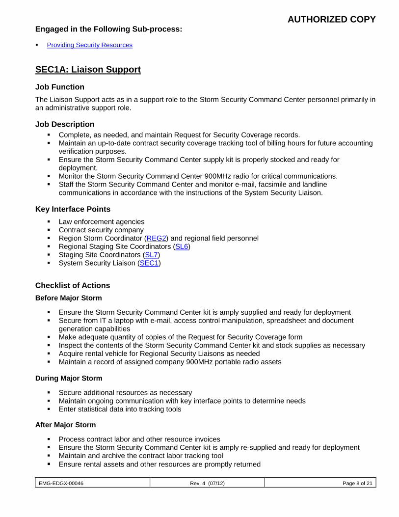
AUTHORIZED COPY
EMG-EDGX-00046 Rev. 4 (07/12) Page 8 of 21
Engaged in the Following Sub-process:
Providing Security Resources
SEC1A: Liaison Support
Job Function The Liaison Support acts as in a support role to the Storm Security Command Center personnel primarily in an administrative support role.
Job Description Complete, as needed, and maintain Request for Security Coverage records. Maintain an up-to-date contract security coverage tracking tool of billing hours for future accounting
verification purposes. Ensure the Storm Security Command Center supply kit is properly stocked and ready for
deployment. Monitor the Storm Security Command Center 900MHz radio for critical communications. Staff the Storm Security Command Center and monitor e-mail, facsimile and landline
communications in accordance with the instructions of the System Security Liaison.
Key Interface Points Law enforcement agencies Contract security company Region Storm Coordinator (REG2) and regional field personnel Regional Staging Site Coordinators (SL6) Staging Site Coordinators (SL7) System Security Liaison (SEC1)
Checklist of Actions Before Major Storm Ensure the Storm Security Command Center kit is amply supplied and ready for deployment Secure from IT a laptop with e-mail, access control manipulation, spreadsheet and document
generation capabilities Make adequate quantity of copies of the Request for Security Coverage form Inspect the contents of the Storm Security Command Center kit and stock supplies as necessary Acquire rental vehicle for Regional Security Liaisons as needed Maintain a record of assigned company 900MHz portable radio assets
During Major Storm Secure additional resources as necessary Maintain ongoing communication with key interface points to determine needs Enter statistical data into tracking tools
After Major Storm Process contract labor and other resource invoices Ensure the Storm Security Command Center kit is amply re-supplied and ready for deployment Maintain and archive the contract labor tracking tool Ensure rental assets and other resources are promptly returned
AUTHORIZED COPY
EMG-EDGX-00046 Rev. 4 (07/12) Page 9 of 21
Tools and Information Needed Guard Post Spreadsheets Maps and wall charts of company locations Company 900MHz desktop radio Laptop computer with Perspective software Staging and Logistic Site information and contact list of staging site personnel Law enforcement agency contact list Voice, e-mail and facsimile communications
Engaged in the Following Sub-process Providing Security Resources
SEC1B: Contract Security Storm Coordinator
Job Function The Contract Security Storm Coordinator acts as the primary contact between Duke Energy and the engaged contract security company. All security coverage and security performance issues will be communicated through the Contract Security Storm Coordinator.
Job Description Facilitate security officer coverage requests in coordination with the contract security command
post. Maintain an up-to-date contract security coverage spreadsheet to track deployed personnel, their
contact information (including cell number and hotel room phone number), and hours of work, and track billing hours.
Ensure security officer logistics, such as housing, food, transportation, etc., has been arranged. If officers are assigned to a Strike Team, this may be coordinated by the Strike Team’s Resource Utilization Coordinator or the assigned Corporate Security Liaison.
Monitor the Storm Security Command Center 900MHz radio for critical communications. Staff the Storm Security Command Center in accordance with the instructions of the System
Security Liaison. Ensure all Security Officers have cellular phones and recommended personal protective equipment. Ensure all Security Officers are aware of their safety and job responsibilities and are been properly
briefed. A job aid listing expectations for security officers is attached as Attachment 3.
Key Interface Points Contract security company System Security Liaison (SEC1) Liaison Support (SEC1A)
Checklist of Actions Before Major Storm
Develop manpower needs and coordinate contract security response with the SEC1 Notify contract security company of deployment needs and timelines Report to the Corporate Security Storm Command Center Process requests for security services coverage using
AUTHORIZED COPY
EMG-EDGX-00046 Rev. 4 (07/12) Page 10 of 21
During Major Storm Manage security coverage, termination of services and accounting of billable hours Act as central point of contact for the contract security provider Issue requests for security services to the contract security company Coordinate logistics and housing for contract security officers Maintain an up-to-date contract security coverage spreadsheet to track deployed personnel, their
contact information, and hours of work, and track billing hours.
After Major Storm
Process requests for termination of security services coverage Ensure the accuracy of billing worksheets Ensure accountability of all personnel and assets utilized in deployment
Tools and Information Needed Guard Post spreadsheets Electronic map program w/ GPS locator Company 900MHz portable radio Maps and wall charts of company locations Staging and Logistic Site information and contact list of staging site personnel Standard Operating Guidelines for contract security force Voice and e-mail communications
Engaged in the Following Sub-process Providing Security Resources
SEC1C: RSVP Coordinator
Job Function This position is responsible for keeping the Corporate Security portion of the RSVP tool current. In addition, this position will support the Corporate Security storm response by updating the RSVP tool to accurately reflect the Corporate Security resource mobilization plan.
Job Description This position is responsible for: Keeping the RSVP tool updated as employees transfer in and out of the Corporate Security storm
organization Being the first point of contact for Corporate Security employees regarding RSVP questions or
concerns Assisting employees when signing up for their storm role Participating in pre-storm season planning
Key Interface Points Corporate Security System Security Liaison Liaison Support Contract Security Storm Coordinator Regional Security Liaison All RSVP Coordinators
AUTHORIZED COPY
EMG-EDGX-00046 Rev. 4 (07/12) Page 11 of 21
Checklist of Actions Before Major Storm 72-96 hours prior, begin identifying Corporate Security employees availability for storm duty and
input data into RSVP tool. 48-72 hours prior, complete employee availability input into the RSVP tool and begin activation of
employees 24-48 hours prior, complete activation of all identified Corporate Security employees 0-24 hours prior, finalize any pre-storm resource allocation plan adjustments in the RSVP tool.
During Major Storm Periodically update resource allocation adjustments in the RSVP tool throughout the restoration
effort Release employees from Corporate Security storm support, as they become available, for use by
other storm organizations Identify released Corporate Security employees that are not able to support other storm
organizations as “Not Available” in the RSVP tool After Major Storm Release all Corporate Security employees from the current storm in the RSVP tool Participate in any lessons learned exercises after each storm event Forward lessons learned results to the System RSVP Coordinator
Tools and Information Needed RSVP Tool RSVP Quick Reference Guidelines RSVP Training Manual
SEC2: Regional Security Liaison
Job Function The Regional Security Liaison acts as a single point of contact to Duke Energy field personnel, primarily addressing security-related concerns on a regional basis during storm restoration activities.
Job Description Interact with Regional Storm management on threat and employee safety issues Ensure that security guard staff have appropriate instructions, equipment, and contact information
by providing a pre-job brief using attachment 3 and 4 Interact with local law enforcement and public officials to facilitate employee, contractor, and
logistical support personnel’s access into disaster areas Carry out non-staff-related security functions, including criminal investigations involving Duke
Energy property, investigating threats by customers, and interfacing with law enforcement agencies Represent Corporate Security on Region storm conference calls when required by the Region
Storm Coordinator (REG2)
Key Interface Points Contract guard force management Law enforcement agencies Region Storm Coordinator (REG2) and regional field personnel Regional Staging Site Coordinators (SL6) Staging Site Coordinators (SL7) System Security Liaison (SEC1)
AUTHORIZED COPY
EMG-EDGX-00046 Rev. 4 (07/12) Page 12 of 21
Checklist of Actions Before Major Storm Inspect the contents of their CS Storm Kit and stock supplies as necessary Ensure familiarity with Region Storm Centers, Mustering Areas, Staging Sites, critical substations,
and Operations Centers Ensure a working relationship has been established with Region Staging and Logistics personnel,
Staging Site Coordinators and Region law enforcement agencies Ensure all Region Storm Centers, Mustering Areas, Staging Sites, critical substations, and
Operations Centers are located on mapping software Ensure company issued 900MHz portable and desktop radios have been tested and are in good
working condition During Major Storm Carry out Security functions, including ethics/criminal investigations involving Duke Energy
personnel or property, investigating threats by customers, and interfacing with law enforcement agencies
Act as central point of contact for region security coverage issues and needs with Region Storm leadership
Communicate all security coverage requests and terminations to the Storm Security Command Center
Represent Corporate Security on Region storm conference calls and work groups as assigned by the System Security Liaison (SEC1)
Inspect and assess the security risks at Region Storm Centers, Mustering Areas, Staging Sites, critical substations, and Operations Centers
After Major Storm Coordinate the termination of security coverage and determine the status of site assets Participate in lessons learned activities
Tools and Information Needed Guard Post Spreadsheets Electronic map program w/ GPS locator Company 900MHz portable radio Laptop computer with Perspective software Staging and Logistic Site information and contact list of staging site personnel Law enforcement agency contact list Voice, e-mail and facsimile communications Four wheel drive SUV as necessary Door placards, “Duke Energy Storm Restoration” Flashing Yellow Beacon Cans of Fix A Flat (3-4) and Jumper Cables Cell phone chargers AC&DC Yellow “Caution” tape
A checklist with recommended personal protective equipment is contained in Attachment 2. If any Duke Energy Employee or contractor is threatened by another employee, customer, or person near a work-site, they should contact 911, and the Security Command Center in accordance with Attachment 5 and the Workplace Violence Prevention and Response procedure (SEC-SUBS-00077)
AUTHORIZED COPY
EMG-EDGX-00046 Rev. 4 (07/12) Page 13 of 21
Engaged in the Following Sub-process Providing Security Resources
Post-Disaster Re-entry Process Post disaster re-entry process refers to plans by State and Local governments to ensure the life safety of citizens following a major disaster by tracking emergency commodities and by limiting access or re-entry into impacted areas. The restoration of electric service to a community has been deemed necessary to ensure life safety. Electric utilities have been granted re-entry access under these plans. These re-entry processes are adopted by State statute and will be utilized during large scale incidents that impact several counties and involve a disaster declaration by the Governor of the State. Local counties and public officials will enforce the curfews or restrictions into the impacted areas. The System Security Liaison (SEC 1) and Regional Security Liaison (SEC 2) need to be aware of re-entry requirements for the impacted areas. Many States will issue an annual placard or other means of identifying those granted access for any disaster that occurs. Placards are valid for a specific period, usually a calendar year.
Checklist of Actions Before Major Storm Ensure familiarity with re-entry process for the assigned region or area of responsibility Ensure adequate supply of Re-Entry placard or certificate on hand in Storm Kit Disseminate placards or certificates to contracted security officers
During Major Storm Provide briefing on requirements of re-entry process and disseminate placards or certificates to
others as needed Coordinate security functions with local law enforcement and/or public officials to facilitate re-entry.
Deployment Procedures for Strike Team Security Security may be part of the deployment package when Duke Energy resources are sent to support restoration efforts for other utilities during an off-system assistance request. While it is the current policy of Duke Energy not to use armed Security Officers, in the event that they are used, Security personnel requirements shall be discussed and mutually agreed upon by the Requesting and Responding Companies prior to deployment. Any deployment of “Security Personnel”, armed or otherwise, must comply with Federal, State, and Local regulations. The Requesting Company will provide vehicle security for parking areas unless specifically agreed otherwise. The Responding Company is responsible for traveling security when needed. There may be instances where security that has travelled with deployed Duke Energy assets (Strike Teams) are kept with the assets even though the destination site has adequate security. If the situation dictates additional security, the need and cost accounting shall be agreed upon by the Requesting Company. The Requesting Company will handle all food, lodging, and incidental support needed by the Responding Company with the exception of food and lodging during travel to and from final work site. All security personnel shall be listed on the Storm Team List under support to ensure cost documentation and tracking.
AUTHORIZED COPY
EMG-EDGX-00046 Rev. 4 (07/12) Page 14 of 21
Request for off-system support will be coordinated by the System Security Liaison (SEC 1) with Designated Duke Energy (Responding Company) Contacts, Duke Energy System Storm Coordinators, and/or Strike Team Leaders. For planning purposes the number of security personnel have been listed on First Wave Deployment Packages that are provided during off-system requests Levels 1-3. Strike Team Security Support during on-system deployments will report to the Strike Team Leaders. Security Officers assigned to Strike Teams may only be utilized to provide security while the team is in transit. Once at the destination and in order to be able to move with the strike team as needed, Officers may be used to augment other security forces and are not to be used to replace watch rotations of assigned officers at established sites. Normally, a Regional Security Liaison from Corporate Security will accompany officers deployed as part of a Strike Team package.
Supplementary Information
Forms Security Coverage Request Form (FRM-EDGX-00001)
Attachments Attachment 1: Corporate Security Pre-Storm Checklist Attachment 2: Corporate Security Personal Protective Equipment Checklist Attachment 3: Corporate Security Pre-Job Brief Attachment 4: Expectations of Security Personnel Job Aid Attachment 5: Workplace Violence Precautions
AUTHORIZED COPY
EMG-EDGX-00046 Rev. 4 (07/12) Page 15 of 21
Attachment 1 Corporate Security Pre-Storm Checklist
MARCH 1 THROUGH JUNE 1 Safety First. Re-familiarize yourself with your storm region including potential Staging and Logistic sites, law enforcement
contacts and infrastructure. Initiate contact with the regional coordinators in each area. Update Corp Security Storm Team Contact Lists. Ensure your storm kit, vehicles, and communications equipment are in order. Disseminate latest version of Corp Security Storm Plan to contracted security vendor.
JUNE 1 THROUGH THE CONCLUSION OF STORM SEASON Safety First. Carefully plan your vacation schedules being mindful of peak season. Ensure your storm kit, vehicles, and communications equipment are in order. Monitor weather throughout the season and maintain occasional contact with storm coordinators. 5 DAYS PRIOR TO THE STORM Safety First. SSL and RSL’s monitor emerging weather reports. SSL places security providers on notice. SSL informs RSL’s to prepare for a field response. SSL and RSL’s begin preliminary discussions on required resources based on projected path and intensity. SSL will monitor business environment for the release of the major storm number and authorize a partial
mobilization when appropriate. Administrative Staff will verify LEA processes for requesting off duty LE support in target areas. 72 HOURS PRIOR TO THE STORM Safety First. SSL and RSL’s monitor emerging weather reports. RSL’s will initiate contact with the regional coordinators in each area. SSL and RSL’s will determine radio requirements for response. SSL and RSL’s participate in any storm related calls invited onto listening for emergent information. SSL will monitor the regulatory environment for the declaration of a state of emergency. Upon declaration, SSL
will request public affairs to obtain a license waiver from the state if necessary. SSL will ensure all System Storm Center phone/fax numbers are working and will verify post documents reflect
the same. SSL will liaison with contract security storm coordinator. SSL will request additional mobilization of contractor resources if appropriate. 48 HOURS PRIOR TO STORM Safety First. RSL’s will begin contractor training/expectation debriefs upon arrival to service territory. SSL and RSL’s participate in any storm related calls invited onto listening for emergent information. RSL’s will maintain contact with the regional coordinators in each respective area. SSL will validate deployment numbers based on published S&L information and preliminary requests from the
business units. 24 HOURS PRIOR TO STORM Safety First. SSL and RSL’s will continue contractor training/expectation debriefs upon arrival to service territory. SSL and RSL’s participate in any storm related calls invited onto listening for emergent information. RSL’s will maintain contact with the regional coordinators in each respective area. SSL will validate deployment numbers based on published S&L information and preliminary requests from the
business units and adjust as necessary.

AUTHORIZED COPY
EMG-EDGX-00046 Rev. 4 (07/12) Page 16 of 21
Attachment 2 Corporate Security Personal Protective Equipment Checklist
• PPE: Hard Hat, Safety Glasses (Clear and Sunglass), Lanyards and Safety Toe Shoes,
Safety Vests. Details on approved PPE can be found in the Protective Equipment Section of the Health & Safety Manual.
• Rain Gear. • Wide Brim Hats: For sun protection. • Bug Spray that contains Deet: Two containers. • Sun Screen, two bottles: At least an SPF 30. • Waterless Hand Wash: Two bottles Hand Sanitizer with at least 62% alcohol. • When being deployed on or off system have at least 2 weeks of clothing. Blue Jeans
are acceptable attire for off system work. • Rubber Boots. • Eye Glass Cleaning Kits. • Work Gloves. • Have sufficient cash with you for two weeks, since ATM machines in the area may
not be working and save the receipts so you can expense them in Concur. • Handi Wipes. • Prescription medications sufficient for expected travel period.
AUTHORIZED COPY
EMG-EDGX-00046 Rev. 4 (07/12) Page 17 of 21
Attachment 3 Pre-Job Brief
1. Take inventory of PPE/Safety Items
2. Familiarize yourself with the vehicle a) adjust seat and mirrors b) verify positions of light switches, turn signals, wipers, cruise controls, door and window
controls c) perform preflight – fluids, tire pressure, gas card, spare tire with jack d) test drive vehicle to familiarize yourself with braking system e) verify your vehicle load is secure and able to drive at highway speeds, if applicable f) verify if air bag is engaged for travel (if so equipped) g) familiarize yourself with travel route h) USE SEAT BELTS WHILE OPERATING VEHICLE 3. Arrive Safely a) Remember, your first priority is to arrive safely b) Be alert to changing speed conditions c) Be alert to blind spots for you and those you are near d) Be alert to road obstacles, such as holes, animals, packaging and failed tire retreads e) Be alert to changing wind conditions and rain f) Don’t get to comfortable or complacent as you travel – stay alert g) Utilize Smith Driving Points if you have attended classes
1) Look ahead – approximately 15 seconds distance 2) Keep your eyes moving – 360 degree awareness 3) Make eye contact with other drivers to verify they know you are there 4) Give yourself a way out – in case someone cuts you off 5) Keep good distance between you and vehicle ahead–approximately 5 seconds
h) Lead cars should communicate with other team members identified road hazards Safety Protocols: This checklist is provided to assist you in conducting your safety briefing(s) for your team when you are deployed. In addition to other safety items you may wish to address, please cover the following: 1. Be aware that some of your team may be: relatively new to the company from parts of the Company that are not part of a Safety Council And therefore may not be as familiar with our safety emphasis / safety rules. And that some of your team may be performing tasks and / or working in an environment
that is not part of their normal day to day work. Therefore, you are encouraged to emphasize safety each day while the Staging Site is in
operation At Duke Energy safety is a value. This means if the task is done right there will be no
injuries or damage. Your task and safety are not two separate parts of a job.
AUTHORIZED COPY
EMG-EDGX-00046 Rev. 4 (07/12) Page 18 of 21
2. Some items your safety briefing should remind your team of include: Their personal safety, the safety of their teammates, and the safety of everyone who comes
to the site is NUMBER 1. The goal is that everyone goes home at the end of the assignment safe and uninjured. Ask each member of your team if they have any personal limitations.
Advise all team members that they are “empowered” to stop the work of anyone onsite if it is seen as unsafe or careless. (Note: Caution should be used here based on the knowledge of what is determined as safe or not, may want to get a second opinion unless it is a flagrant safety issue). They are to immediately notify the Team Leader if they observe anything of this nature. This includes all company contractor and any other support personnel on the site.
You are not expected to be verbally or physically abused, report any incidents immediately to your team leader and Regional Security Liaison as needed. All folks who access the staging and logistics site are expected to follow your directions.
If “unauthorized personnel” (i.e. customers, visitors, etc...) are observed on the site, escort them off the site. This is primarily for the safety of those visitors who may not be aware of the hazards and dangers of the site as well as ensuring the Team Leader knows who is on the site. (Note: Should be signs in the staging kit “Authorized Personnel Only”)
At each shift change, do a safety briefing. Use the list below as a guide. Cover any safety hazards observed previously. Safety shall be of first importance in the performance of all duties. Each employee is
responsible for personal safety and the safety of others. Let’s watch out for each other! The weather conditions and what hazards that presents at the site. Cold and hot weather
precautions. Make sure there is adequate shelter for inclement weather. This can be as simple as a
vehicle stationed nearby. Go over a plan of action if sudden storms come up while folks are exposed and on duty. Make sure everyone has adequate drinking supplies for warm or hot weather and warm
beverages for cool or cold weather. This also goes for food; make sure everyone gets their meals or snacks as needed.
Develop a “buddy” system of checking on each other at regular intervals . Day / night operations – personal visibility, potential walking / driving hazards Driving. If anyone is observed driving erratically including going too fast, stop it, or report it if
needed. Road conditions, road hazards, overhead hazards posed by wind conditions. Placement of equipment that may impede the view of other vehicles. Driving vehicles that they may not be accustomed to driving. Backing precautions on the site. Large vehicles, numerous vehicles on site. Golf cart operation may be necessary. No one is to drive a golf cart until they have been
checked out in the operation. Golf carts are to be driven at a safe speed when in use. Drivers are responsible for
alerting their passengers to speed and direction changes and upcoming road hazards. There will be no hanging on or piggy backing; passengers must ride on a seat that is
made for riding in.
AUTHORIZED COPY
EMG-EDGX-00046 Rev. 4 (07/12) Page 19 of 21
First aid kit locations and blood born pathogen kits are on site (verify that none of the contents are out of date – replace if necessary).
Fire extinguisher locations on site Make sure everyone has Security contact information as well as emergency contacts
and non-emergency numbers for law enforcement and hospitals. Fatigue- Do not drive or perform other duties while fatigued, you are responsible to let your
team leader know when you need a break. If you are getting ready to perform a task and have concerns about how to perform it
safely, stop and ask the team leader. If you are asked to perform a task and you have any limitation that could hinder you
please let one of your team leaders know. How to respond to a security issue on the site (what to do) Make sure everyone of the team has a set of written directions to the site on their person in
the event they need to call 911 and give the emergency dispatcher directions to the site. Familiarize yourself with facility evacuation plan in case of fire or other emergency at the
site Beware of conditions and surroundings at off site locations (i.e. hotels/motels, restaurants, etc) Do not to place yourself in an area that is not well lit unless you are with other personnel
with whom you are familiar, establish a “buddy” system for night time duty. No job is so important that we cannot take time to do it safely! Remember we know to do the job safely it will take more time. Take the time that is needed to do the job right!
AUTHORIZED COPY
EMG-EDGX-00046 Rev. 4 (07/12) Page 20 of 21
Attachment 4 Expectations of Security Personnel during Storm Restoration Efforts Job Aid
Staging Areas, Operations Centers, Generation Plants
Safety is the first priority! In addition to all emergency post orders, please adhere to the following: • Upon arrival to the site, each shift must check in with the Duke Energy site manager, logistics coordinator, or
person of authority. Ensure that all requests they may have are documented and acted upon. If relieving the post, the post officer must ensure an adequate and appropriate turnover of information, post orders, special requirements, etc. with the relief officer.
• Maintain clear and accurate logs of all your activities including time on and off shift and your replacement. You
must not abandon your post until properly relieved. Notify your management immediately if you are not relieved. • Maintain a visible presence at the entrance(s) to the staging site during daytime hours. Conduct vehicle or foot
patrols during hours of darkness when the entrance(s) is closed. Site specific directions may be provided by your management team or Duke Energy Corporate Security.
• Request the identity and reason for people wishing to enter the site that are not related to the recovery effort.
Duke Energy employees carry identification badges. Non-PGN crews and vendors should be easily identifiable as they will be operating company vehicles or carry identification badges. Deny access to any person who does not meet the above requirements. Notify a person of authority, your management, or Duke Energy Corporate Security if any person attempts to enter that you believe may not be authorized. In the event a person/vehicle forces their way past you, contact 911 for police response then your management and Corporate Security. A list will be provided to security of all authorized vendors and companies permitted to access staging areas within a few days of establishment of a staging area.
• Do not allow the general public or the media into the staging sites. These are access restricted areas for safety
reasons. • Protect company and contractor personnel and equipment at the staging site. Notify the person of authority of
any immediate threats. All threat and security-related concerns should be reported to your management or Corporate Security immediately. Record in your log book necessary information for an investigation including, but not limited to, e.g. physical description, make/model/color of vehicle, license plate #, etc.
• Direct customers with service concerns to call the service line at 1-800-419-6356 for Carolina customers and 1-
800-228-8485 for Florida customers. Do not engage in conversation with any person not associated with your company or Duke Energy. Reporters will solicit information from you and quote you in the media.
• If a customer identifies a hazardous or emergency situation, notify a Logistics team member who will take the
information and contact line & service. • Do not direct traffic as trucks or vehicles are entering or leaving the staging site. It is unlawful to do so in without
certification. Security personnel are not to engage in pumping fuel. • If and when the staging site is closed for the night, keep personnel out except authorized company and contractor
personnel.
• If at any time you receive a directive or instruction requesting that you perform, participate, or otherwise engage in any activity that contradicts any of the above information, and the requestor of such is not a member or your management team or Duke Energy Corporate Security, you shall immediately contact your management or Corporate Security for clarification before taking any action.
AUTHORIZED COPY
EMG-EDGX-00046 Rev. 4 (07/12) Page 21 of 21
Attachment 5 Workplace Violence Precautions During Storm Restoration
Predicting Violence- Indicators
• Customer verbalizes a threat of violence • Manipulative Threat/Condition • Unconditional Threat • Veiled Threat • Direct Threat
• “Your Gut Level Feeling.” • What does the gut level feeling tell you about this person? “Don’t ignore your intuitive
nature” This is your bodies built in warning mechanism” Listen to it! • This is the normal progression of angry or upset people.
o Anxiety - sweating, pacing, fast breathing, red face and fist clenching o Loss of Verbal Control - using profanity, voice tone, etc. o Physical Attack
• If the situation escalates to the point where you feel threatened or you believe a physical attack may be made against you…. o Calmly and quickly walk away and immediately leave the area- contact 911 and the Security
Command Center at (888) 275-4357 or (919) 546-7599. o If you are presented with no other option except to defend yourself from physical harm, only
use the amount of force necessary to defend yourself and provide for enough time to immediately leave the area and contact 911 and the Regional Security Liaison.
o Goal. Avoid all physical altercations. Both Employee and Customer will be in a win-win situation.
Avoid-
• Assuming you know how the customer feels without asking. • Ignoring indirect signs of displeasure. • Suggesting a solution before you’ve heard the customer out. • Apologizing to the customer before listening and responding with empathy. • Making suggestions without involving the customer.
Have a plan-
• Expand your awareness of the environment o Develop escape route o Identify obstacles and defensive tools o Maintain a safe distance
“Taking the Heat”
• Hear them out. • Empathize with them. • Apologize for the problem or inconvenience, which is not the same as accepting blame. • Take responsibility for action by:
- Further clarifying the situation. - Meeting or exceeding customer’s needs. - Confirming customer’s satisfaction.
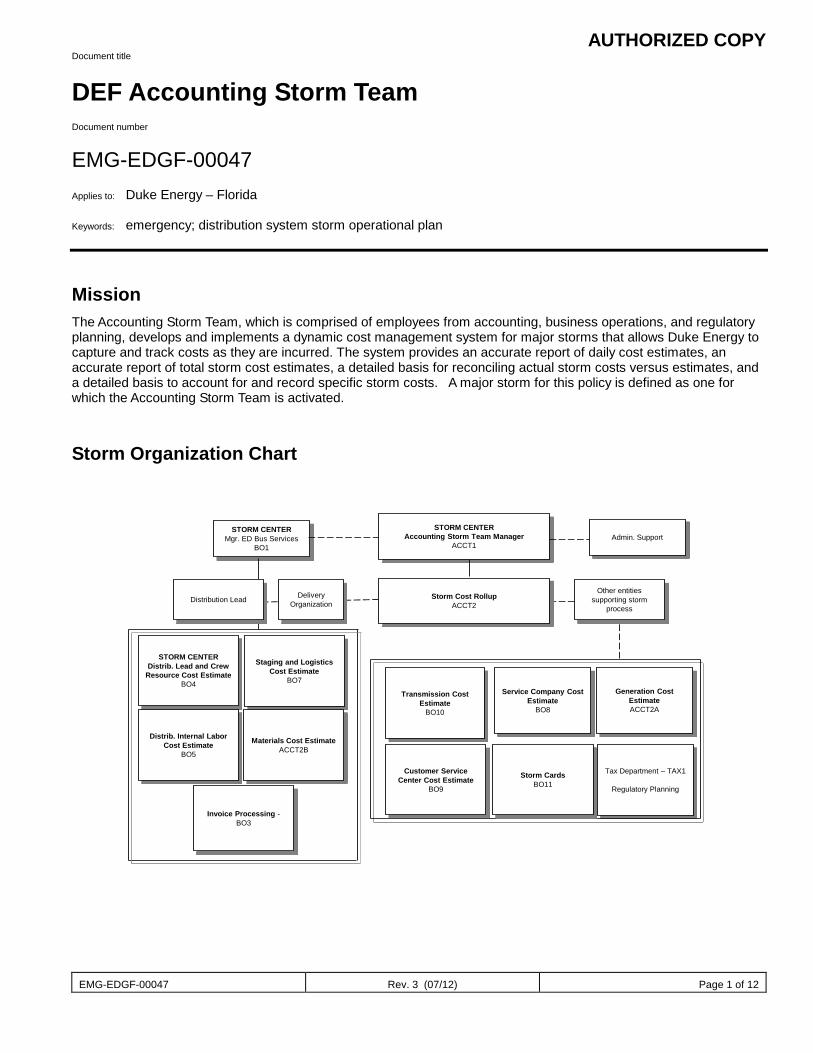
AUTHORIZED COPY
EMG-EDGF-00047 Rev. 3 (07/12) Page 1 of 12
Document title
DEF Accounting Storm Team Document number
EMG-EDGF-00047 Applies to: Duke Energy – Florida Keywords: emergency; distribution system storm operational plan
Mission The Accounting Storm Team, which is comprised of employees from accounting, business operations, and regulatory planning, develops and implements a dynamic cost management system for major storms that allows Duke Energy to capture and track costs as they are incurred. The system provides an accurate report of daily cost estimates, an accurate report of total storm cost estimates, a detailed basis for reconciling actual storm costs versus estimates, and a detailed basis to account for and record specific storm costs. A major storm for this policy is defined as one for which the Accounting Storm Team is activated.
Storm Organization Chart
STORM CENTERMgr. ED Bus Services
BO1
Storm Cost RollupACCT2
STORM CENTERDistrib. Lead and Crew
Resource Cost EstimateBO4
Distrib. Internal Labor Cost Estimate
BO5
Transmission Cost Estimate
BO10
Service Company Cost Estimate
BO8
Staging and Logistics Cost Estimate
BO7Generation Cost
EstimateACCT2A
Materials Cost EstimateACCT2B
STORM CENTERAccounting Storm Team Manager
ACCT1
Invoice Processing -BO3
Tax Department – TAX1
Regulatory Planning
Customer Service Center Cost Estimate
BO9
Admin. Support
Other entities supporting storm
process
Delivery Organization
Storm CardsBO11
Distribution Lead

AUTHORIZED COPY
EMG-EDGF-00047 Rev. 3 (07/12) Page 2 of 12
Sub-processes:
Before and During Major Storm After Major Storm
The flowcharts below provide a detailed view of these functional processes:
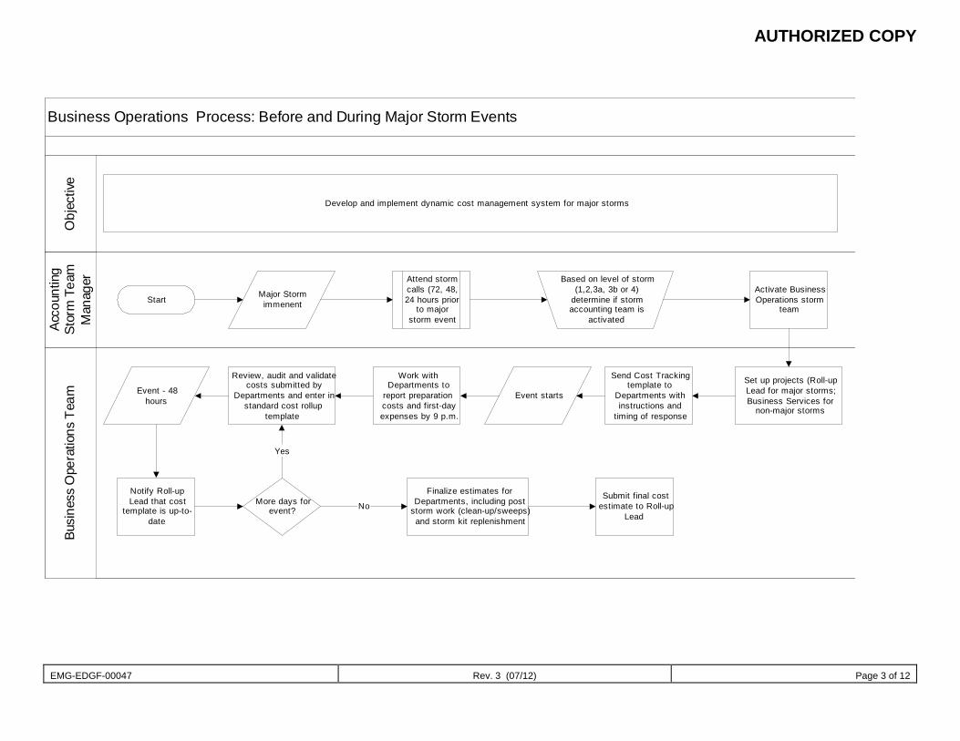
AUTHORIZED COPY
EMG-EDGF-00047 Rev. 3 (07/12) Page 3 of 12
Business Operations Process: Before and During Major Storm Events
Acco
untin
gSt
orm
Tea
mM
anag
erBu
sine
ss O
pera
tions
Tea
mO
bjec
tive
Develop and implement dynamic cost management system for major storms
StartMajor Storm
immenent
Attend stormcalls (72, 48,24 hours prior
to majorstorm event
Activate BusinessOperations storm
team
Set up projects (Roll-upLead for major storms;Business Services for
non-major storms
Send Cost Trackingtemplate to
Departments withinstructions and
timing of response
Event starts
Work withDepartments to
report preparationcosts and first-dayexpenses by 9 p.m.
Review, audit and validatecosts submitted by
Departments and enter instandard cost rollup
template
Event - 48hours
Notify Roll-upLead that cost
template is up-to-date
More days forevent?
Finalize estimates forDepartments, including post
storm work (clean-up/sweeps)and storm kit replenishment
Submit final costestimate to Roll-up
Lead
Based on level of storm(1,2,3a, 3b or 4)
determine if stormaccounting team is
activated
No
Yes
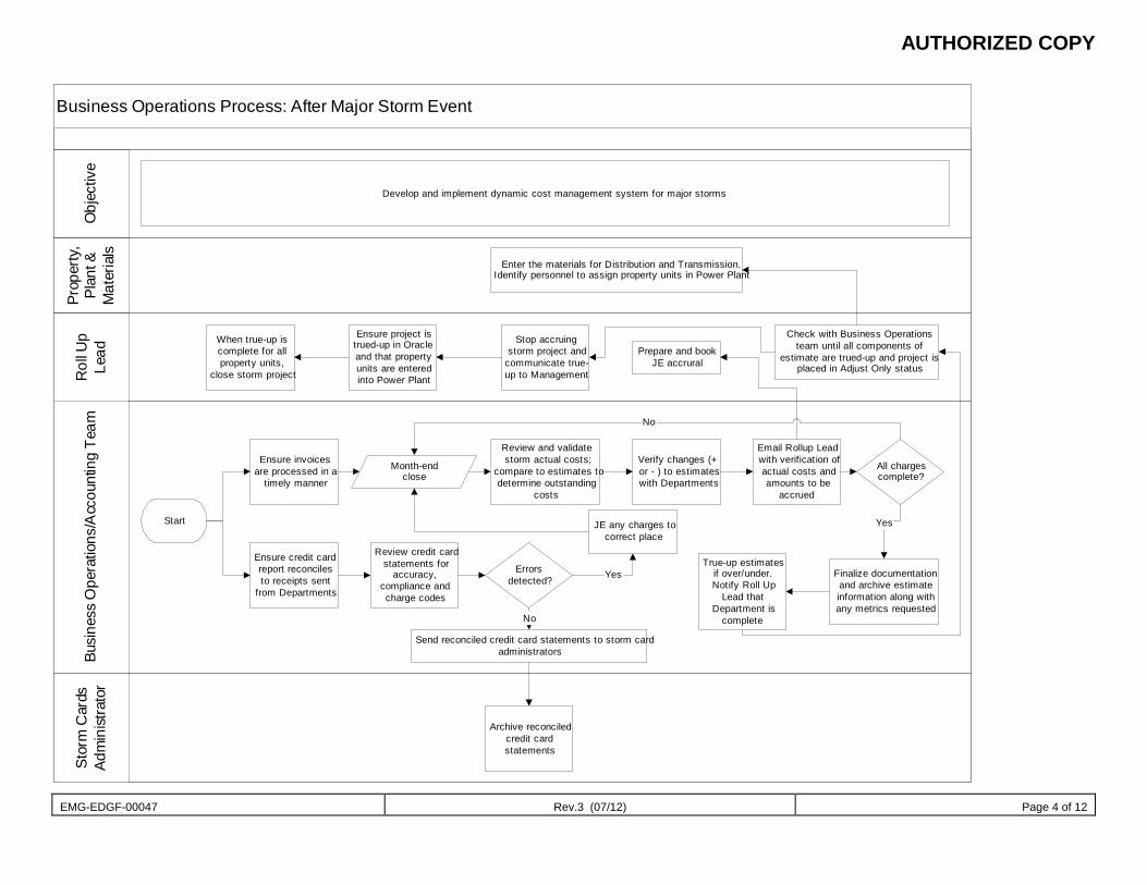
AUTHORIZED COPY
EMG-EDGF-00047 Rev.3 (07/12) Page 4 of 12
Business Operations Process: After Major Storm Event
Prop
erty
,Pl
ant &
Mat
eria
ls
Rol
l Up
Lead
Busi
ness
Ope
ratio
ns/A
ccou
ntin
g Te
amSt
orm
Car
dsAd
min
istra
tor
Obj
ectiv
e
Develop and implement dynamic cost management system for major storms
Enter the materials for Distribution and Transmission.Identify personnel to assign property units in Power Plant
Start
Ensure invoicesare processed in a
timely manner
Ensure credit cardreport reconcilesto receipts sent
from Departments
Month-endclose
Review credit cardstatements for
accuracy,compliance andcharge codes
When true-up iscomplete for allproperty units,
close storm project
Ensure project istrued-up in Oracleand that propertyunits are enteredinto Power Plant
Stop accruingstorm project and
communicate true-up to Management
Prepare and bookJE accrural
Check with Business Operationsteam until all components of
estimate are trued-up and project isplaced in Adjust Only status
Review and validatestorm actual costs;
compare to estimates todetermine outstanding
costs
Verify changes (+or - ) to estimateswith Departments
Email Rollup Leadwith verification ofactual costs andamounts to be
accrued
All chargescomplete?
JE any charges tocorrect place
Finalize documentationand archive estimateinformation along withany metrics requested
Errorsdetected?
Send reconciled credit card statements to storm cardadministrators
True-up estimatesif over/under.Notify Roll Up
Lead thatDepartment is
complete
Archive reconciledcredit cardstatements
No
Yes
No
Yes
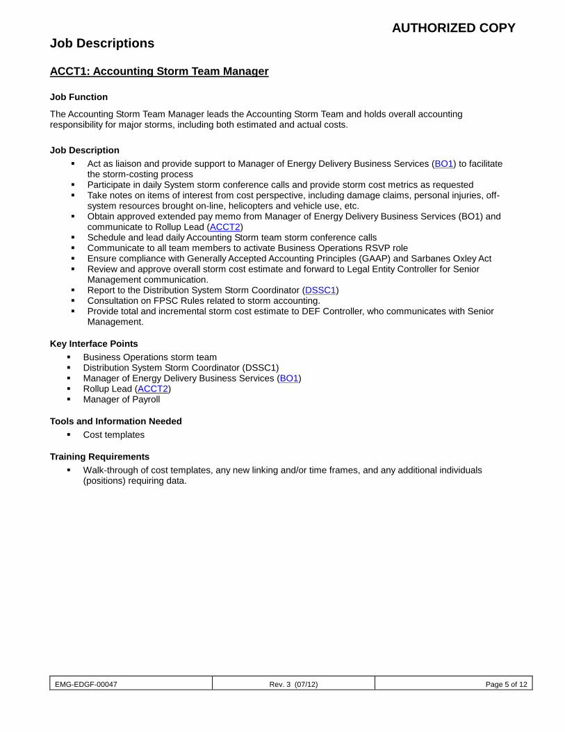
AUTHORIZED COPY
EMG-EDGF-00047 Rev. 3 (07/12) Page 5 of 12
Job Descriptions
ACCT1: Accounting Storm Team Manager
Job Function
The Accounting Storm Team Manager leads the Accounting Storm Team and holds overall accounting responsibility for major storms, including both estimated and actual costs.
Job Description Act as liaison and provide support to Manager of Energy Delivery Business Services (BO1) to facilitate
the storm-costing process Participate in daily System storm conference calls and provide storm cost metrics as requested Take notes on items of interest from cost perspective, including damage claims, personal injuries, off-
system resources brought on-line, helicopters and vehicle use, etc. Obtain approved extended pay memo from Manager of Energy Delivery Business Services (BO1) and
communicate to Rollup Lead (ACCT2) Schedule and lead daily Accounting Storm team storm conference calls Communicate to all team members to activate Business Operations RSVP role Ensure compliance with Generally Accepted Accounting Principles (GAAP) and Sarbanes Oxley Act Review and approve overall storm cost estimate and forward to Legal Entity Controller for Senior
Management communication. Report to the Distribution System Storm Coordinator (DSSC1) Consultation on FPSC Rules related to storm accounting. Provide total and incremental storm cost estimate to DEF Controller, who communicates with Senior
Management.
Key Interface Points Business Operations storm team Distribution System Storm Coordinator (DSSC1) Manager of Energy Delivery Business Services (BO1) Rollup Lead (ACCT2) Manager of Payroll
Tools and Information Needed Cost templates
Training Requirements Walk-through of cost templates, any new linking and/or time frames, and any additional individuals
(positions) requiring data.
AUTHORIZED COPY
EMG-EDGF-00047 Rev. 3 (07/12) Page 6 of 12
ACCT2: Rollup Lead
Job Function
The Rollup Lead is responsible for consolidating the estimated costs associated with on-system contractors and internal Duke Energy crews that move out of their native territory (where they normally work). The Rollup Lead also serves as backup to the Accounting Storm Team Manager.
Job Description
Acts as a backup to Accounting Storm Team Manager
Responsible for setting up storm WBS code when a universal storm project is considered appropriate (excluding Duke Energy Service Company WBS code) and communicating the WBS code to Accounting Storm Team and Operations. (See 3.2.4)
Communicate, via “Major Storm Team” email address, approved extended pay memo.
Coordinate Accounting Storm Team conference calls as necessary.
Communicate project and appropriate storm charging information.
Communicate folder name on Accounting Shared Drive where files are to be stored for current storm
Perform consolidation or rollup of total Storm Cost estimate using data gathered from members of Accounting Storm Team (for on-system major storms). For on-system storms that do not elevate to the level of requiring a universal major storm project, consolidate the ED, Transmission, Service Company and Generation total actual storm costs (as provided by the storm team members) to determine if the threshold for recoverability has been met.
Coordinate financial metrics reporting and timing.
Record Storm Cost accrual in the general ledger and true up the estimate to actual costs using data gathered from members of Accounting Storm Team.
Act as a liaison with Audit Services Department, Regulatory Accounting, and Tax Department. Report to the Distribution System Storm Coordinator (DSSC1) Prepare FPSC required financial data. Maintain Accounting Storm Team organizational chart.
Thorough understanding of FPSC rules related to storm reserve accounting.
Key Interface Points Accounting Storm Team Manager (ACCT1) Audit Services Department Accounting Storm Team members Distribution System Storm Coordinator (DSSC1) Human Resources and Payroll Tax Department
Tools and Information Needed Cost templates
Training Requirements Walkthrough of cost templates, any new linking and/or time frames and any additional individuals
(position) requiring data.
AUTHORIZED COPY
EMG-EDGF-00047 Rev. 3 (07/12) Page 7 of 12
BO1: Manager of Energy Delivery Business Services Communicate/discuss with the Distribution System Storm Coordinator (DSSC1) the need to implement
extended pay. Approve and draft extended pay memo, obtain signatures and forward to Payroll Department, Accounting
Storm Team Manager (ACCT1) and Rollup Lead (ACCT2). Provide operational support and provide consultation as needed.
TAX1: Tax Department, Regulatory Planning and Materials & Plant Accounting
Provide support for internal, external and regulatory audits/inquiries, as needed.
Communicates changes in storm recover, as ordered by the Public Service Commission.
Materials Accounting to consult, as needed, on property identification and close out of projects. Distribution Lead
Job Function
The Distribution Lead is responsible for consolidating the estimated costs associated with resources brought in from off-system. The Distribution Lead also serves as backup and reviewer for all Distribution related storm roles.
Job Description
Participate in Accounting Storm Team conference calls as necessary.
Communicate, via “Major Storm Team” email address, approved extended pay memo.
Thorough understanding of FPSC rules related to storm reserve accounting.
Off-System Specific Items:
Responsible for setting up storm WBS code when a storm project is considered appropriate for off-system events (excluding Duke Energy Service Company WBS code) and communicating the WBS code to Accounting Storm Team and Operations.
Perform consolidation or rollup of total Storm Cost estimate for off-system storms using data gathered from members of Accounting Storm Team.
Billing information, including approval from ED Business Services Manager, to be provided by Distribution Lead to LE Assistant Controller. Assistant Controller’s unit to process bills.
On-System Specific Items:
For on-system major storms (where a universal storm project is set up by the Accounting Storm Team Lead), coordinate the estimates, analysis and any adjusting entries provided by the ED group.
For storms that do not elevate to the level of requiring a universal major storm project, the Distribution Lead will set up cost management projects for ED to use and will track and analyze the costs. Communicate these costs to the Accounting Storm Team Manager and Accounting Storm Team Lead to allow for the overall evaluation of recoverability.
Distribute extended pay approval via “Major Storm Team” e-mail address; ensure the Manager of Payroll receives the documented approval.
AUTHORIZED COPY
EMG-EDGF-00047 Rev. 3 (07/12) Page 8 of 12
BO3: Contract Invoice Processor
Energy Delivery Contracts group is responsible for processing all off-system, on-system and SEE companies invoices (mutual assistance), including hiring temporary workers as necessary (Business Services will assist in screening temporary applications). Service Company- Purchasing is responsible for their invoices for S&L sites not paid on credit card. All other departments are responsible for processing any miscellaneous invoices, where storm cards could not be utilized.
Manage process of review, audit and approval of invoices.
Ensure Disbursement Services receives approved invoices in a timely manner for payment.
Collaborate with Business Services to utilize template for invoice process through receipt, verification, approval, payment of invoices.
Provide support as necessary to Distribution Crew Resource Estimator and others for actual costs/accrual requirements.
Provide support for internal, external and regulatory audits/inquiries, as needed.
Provide support for financial metrics.
BO4: Distribution Crew Resource Estimator
Utilize the web based crew resource tracking tool to develop the Distribution contract crews cost estimate.
Interface with Resource Management and Contract Services to validate the average hourly contractor rates based on storm demographics. ie: if crews are on OT coming in or DT.
Provide forecast for overall estimate rollup by day, including travel home and rest time, including update on daily calls.
Monitor monthly actual charges and provide support for accrual to the Rollup Lead (or, to the Distribution Lead for storms that are not tracked using a universal major storm project).
Maintain all supporting documentation for the cost estimate and actual costs. Once storm costs are final and all actual costs have been recorded, auditable supporting documentation should be forwarded to the Rollup Lead to be archived for storms that use a universal major storm project.
Collaborate with Business Services to utilize template for invoice process through receipt, verification, approval, payment of invoices.
Understanding of FPSC storm reserve rules; especially as they relate to line and tree contractors.
Provide support for internal, external and regulatory audits/inquiries, as needed.
Provide support for financial metrics.
Reports to the Distribution System Storm Center.
BO5: Distribution Internal Labor Resource Estimator
Utilize the web base crew resource tracking tool to develop the Distribution internal labor resource cost estimate, in conjunction with business performance report on internal crew tracking.
Interface with Human Resources to validate the average hourly employee rates.
Provide forecast for overall estimate rollup by day, including travel home and rest time.
Daily collect RSVP activation reports for validation of assumption on how many support personnel are working the storm, excluding service company employees. Obtain RSVP log sheets from Staging & Logistics Cost Estimator to validate number of service company employees.
Calculate base labor cost for internal resources. Record journal entries necessary to disallow costs out of storm project.
Monitor monthly actual charges and provide support for accrual to the Rollup Lead (or, to the Distribution Lead for storms that are not tracked using a universal major storm project).
AUTHORIZED COPY
EMG-EDGF-00047 Rev. 3 (07/12) Page 9 of 12
Maintain all supporting documentation for the cost estimate and actual costs. Once storm costs are final and all actual costs have been recorded, auditable supporting documentation should be forwarded to the Rollup Lead to be archived for storms that use a universal major storm project.
Ensure projects are being charged appropriately, including review of payroll reports available through Business Objects.
Understanding of FPSC storm reserve rules, especially as they relate to internal labor and related burdening costs.
Provide support for internal, external and regulatory audits/inquiries, as needed.
Provide support for financial metrics.
BO7: Staging and Logistics Cost Estimator
Interface with Staging and Logistics Manager to develop cost estimate for lodging, meals and staging and logistics site costs (ex. Tents, rentals, etc.).
Interface with Purchasing and Supply Chain for purchasing needs.
Collect daily S&L and field office spending reports, also receive RSVP activation reports. Segregate Service Company employees and communicate to Service Company Cost Estimator to ensure all head count charge through the service company to Energy Delivery. Monitor monthly actual charges and provide support for accrual to the Rollup Lead (or, to the Distribution Lead for storms that are not tracked using a universal major storm project).
Maintain all supporting documentation for the cost estimate and actual costs, including credit card reconciliations. Once storm costs are final and all actual costs have been recorded, auditable supporting documentation should be forwarded to the Rollup Lead to be archived for storms that use a universal major storm project.
Provide support for internal, external and regulatory audits/inquiries, as needed.
Provide support for financial metrics.
BO8: Service Company Cost Estimator
Interface with all Service Company departments to consolidate storm cost estimates via templates. (ex. Corporate Communication, Human Resources, Information Technology and Telecommunication, Security, etc.).
Provide support and guidance to all Service Company departments on what can be charged to the storm and how to appropriately charge storm cost. Emphasize that hotel and rentals should be made through the travel center centrally; all meals should be eaten at staging or field offices where possible.
Communicate to departments to include all service company employees in their estimate including employees deployed to other storm roles, such as Staging and Logistics or Damage Assessment. Note: There is a separate line on the template for RSVP volunteers. It’s a regulation that all service company labor be billed from the service company to other entities.
Validate the hourly rate for Service Company internal labor.
Develop rollup Service Company cost estimate.
Collect cost templates from each department in the service company.
Verify each department has included all cost items.
Monitor monthly actual charges and provide support for accrual to the Rollup Lead for storms that use a universal major storm project.
Maintain all supporting documentation for the cost estimate and actual costs, including credit card reconciliations. Once storm costs are final and all actual costs have been recorded, auditable supporting documentation should be forwarded to the Rollup Lead to be archived.
Understanding of FPSC storm reserve rules.
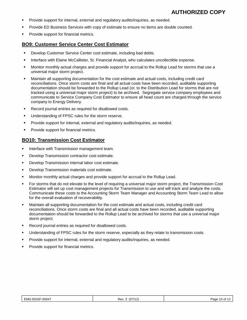
AUTHORIZED COPY
EMG-EDGF-00047 Rev. 3 (07/12) Page 10 of 12
Provide support for internal, external and regulatory audits/inquiries, as needed.
Provide ED Business Services with copy of estimate to ensure no items are double counted.
Provide support for financial metrics.
BO9: Customer Service Center Cost Estimator
Develop Customer Service Center cost estimate, including bad debts.
Interface with Elaine McCallister, Sr. Financial Analyst, who calculates uncollectible expense.
Monitor monthly actual charges and provide support for accrual to the Rollup Lead for storms that use a universal major storm project.
Maintain all supporting documentation for the cost estimate and actual costs, including credit card reconciliations. Once storm costs are final and all actual costs have been recorded, auditable supporting documentation should be forwarded to the Rollup Lead (or, to the Distribution Lead for storms that are not tracked using a universal major storm project) to be archived. Segregate service company employees and communicate to Service Company Cost Estimator to ensure all head count are charged through the service company to Energy Delivery.
Record journal entries as required for disallowed costs.
Understanding of FPSC rules for the storm reserve.
Provide support for internal, external and regulatory audits/inquiries, as needed.
Provide support for financial metrics.
BO10: Transmission Cost Estimator
Interface with Transmission management team.
Develop Transmission contractor cost estimate.
Develop Transmission internal labor cost estimate.
Develop Transmission materials cost estimate.
Monitor monthly actual charges and provide support for accrual to the Rollup Lead.
For storms that do not elevate to the level of requiring a universal major storm project, the Transmission Cost Estimator will set up cost management projects for Transmission to use and will track and analyze the costs. Communicate these costs to the Accounting Storm Team Manager and Accounting Storm Team Lead to allow for the overall evaluation of recoverability.
Maintain all supporting documentation for the cost estimate and actual costs, including credit card reconciliations. Once storm costs are final and all actual costs have been recorded, auditable supporting documentation should be forwarded to the Rollup Lead to be archived for storms that use a universal major storm project.
Record journal entries as required for disallowed costs.
Understanding of FPSC rules for the storm reserve, especially as they relate to transmission costs.
Provide support for internal, external and regulatory audits/inquiries, as needed.
Provide support for financial metrics.
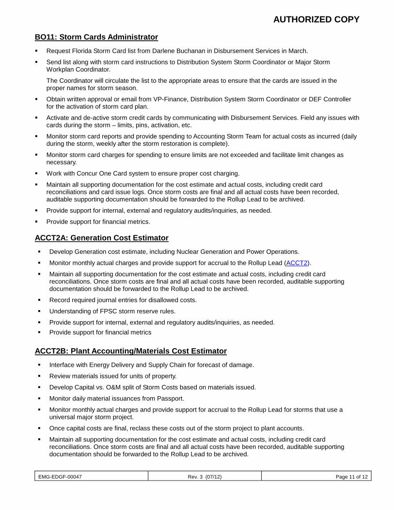
AUTHORIZED COPY
EMG-EDGF-00047 Rev. 3 (07/12) Page 11 of 12
BO11: Storm Cards Administrator
Request Florida Storm Card list from Darlene Buchanan in Disbursement Services in March.
Send list along with storm card instructions to Distribution System Storm Coordinator or Major Storm Workplan Coordinator.
The Coordinator will circulate the list to the appropriate areas to ensure that the cards are issued in the proper names for storm season.
Obtain written approval or email from VP-Finance, Distribution System Storm Coordinator or DEF Controller for the activation of storm card plan.
Activate and de-active storm credit cards by communicating with Disbursement Services. Field any issues with cards during the storm – limits, pins, activation, etc.
Monitor storm card reports and provide spending to Accounting Storm Team for actual costs as incurred (daily during the storm, weekly after the storm restoration is complete).
Monitor storm card charges for spending to ensure limits are not exceeded and facilitate limit changes as necessary.
Work with Concur One Card system to ensure proper cost charging.
Maintain all supporting documentation for the cost estimate and actual costs, including credit card reconciliations and card issue logs. Once storm costs are final and all actual costs have been recorded, auditable supporting documentation should be forwarded to the Rollup Lead to be archived.
Provide support for internal, external and regulatory audits/inquiries, as needed.
Provide support for financial metrics.
ACCT2A: Generation Cost Estimator
Develop Generation cost estimate, including Nuclear Generation and Power Operations.
Monitor monthly actual charges and provide support for accrual to the Rollup Lead (ACCT2).
Maintain all supporting documentation for the cost estimate and actual costs, including credit card reconciliations. Once storm costs are final and all actual costs have been recorded, auditable supporting documentation should be forwarded to the Rollup Lead to be archived.
Record required journal entries for disallowed costs.
Understanding of FPSC storm reserve rules.
Provide support for internal, external and regulatory audits/inquiries, as needed. Provide support for financial metrics
ACCT2B: Plant Accounting/Materials Cost Estimator
Interface with Energy Delivery and Supply Chain for forecast of damage.
Review materials issued for units of property.
Develop Capital vs. O&M split of Storm Costs based on materials issued.
Monitor daily material issuances from Passport.
Monitor monthly actual charges and provide support for accrual to the Rollup Lead for storms that use a universal major storm project.
Once capital costs are final, reclass these costs out of the storm project to plant accounts.
Maintain all supporting documentation for the cost estimate and actual costs, including credit card reconciliations. Once storm costs are final and all actual costs have been recorded, auditable supporting documentation should be forwarded to the Rollup Lead to be archived.
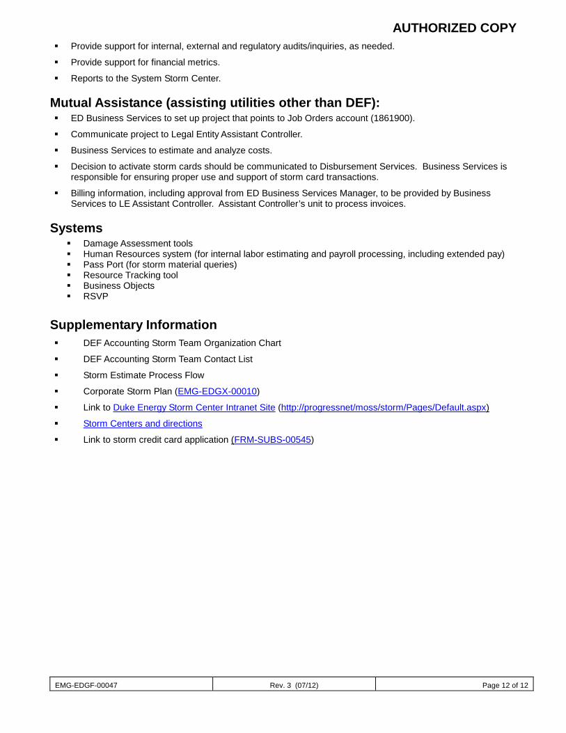
AUTHORIZED COPY
EMG-EDGF-00047 Rev. 3 (07/12) Page 12 of 12
Provide support for internal, external and regulatory audits/inquiries, as needed.
Provide support for financial metrics.
Reports to the System Storm Center.
Mutual Assistance (assisting utilities other than DEF): ED Business Services to set up project that points to Job Orders account (1861900).
Communicate project to Legal Entity Assistant Controller.
Business Services to estimate and analyze costs.
Decision to activate storm cards should be communicated to Disbursement Services. Business Services is responsible for ensuring proper use and support of storm card transactions.
Billing information, including approval from ED Business Services Manager, to be provided by Business Services to LE Assistant Controller. Assistant Controller’s unit to process invoices.
Systems Damage Assessment tools Human Resources system (for internal labor estimating and payroll processing, including extended pay) Pass Port (for storm material queries) Resource Tracking tool Business Objects RSVP
Supplementary Information DEF Accounting Storm Team Organization Chart
DEF Accounting Storm Team Contact List
Storm Estimate Process Flow
Corporate Storm Plan (EMG-EDGX-00010)
Link to Duke Energy Storm Center Intranet Site (http://progressnet/moss/storm/Pages/Default.aspx)
Storm Centers and directions
Link to storm credit card application (FRM-SUBS-00545)
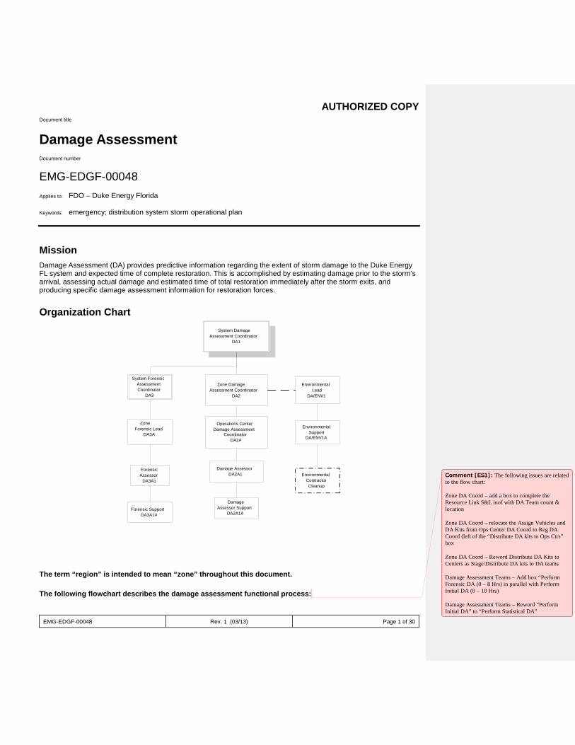
AUTHORIZED COPY
EMG-EDGF-00048 Rev. 1 (03/13) Page 1 of 30
Document title
Damage Assessment Document number
EMG-EDGF-00048 Applies to: FDO – Duke Energy Florida Keywords: emergency; distribution system storm operational plan
Mission Damage Assessment (DA) provides predictive information regarding the extent of storm damage to the Duke Energy FL system and expected time of complete restoration. This is accomplished by estimating damage prior to the storm’s arrival, assessing actual damage and estimated time of total restoration immediately after the storm exits, and producing specific damage assessment information for restoration forces.
Organization Chart
The term “region” is intended to mean “zone” throughout this document.
The following flowchart describes the damage assessment functional process:
System Damage Assessment Coordinator
DA1
Zone Damage Assessment Coordinator
DA2 Environmental
Lead DA/ENV1
Operations Center Damage Assessment
Coordinator DA2A
Damage Assessor DA2A1
Environmental Support
DA/ENV1A
Environmental Contractor Cleanup
Damage Assessor Support
DA2A1A
System Forensic Assessment Coordinator
DA3
Zone Forensic Lead
DA3A
Forensic Assessor
DA3A1
Forensic Support DA3A1A
Comment [ES1]: The following issues are related to the flow chart: Zone DA Coord – add a box to complete the Resource Link S&L inof with DA Team count & location Zone DA Coord – relocate the Assign Vehicles and DA Kits from Ops Center DA Coord to Reg DA Coord (left of the “Distribute DA kits to Ops Ctrs” box Zone DA Coord – Reword Distribute DA Kits to Centers as Stage/Distribute DA kits to DA teams Damage Assessment Teams – Add box “Perform Forensic DA (0 – 8 Hrs) in parallel with Perform Initial DA (0 – 10 Hrs) Damage Assessment Teams – Reword “Perform Initial DA” to “Perform Statistical DA”
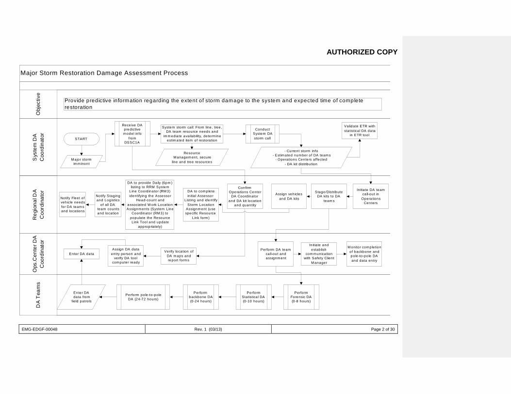
AUTHORIZED COPY
EMG-EDGF-00048 Rev. 1 (03/13) Page 2 of 30
Major Storm Restoration Damage Assessment Process
Sys
tem
DA
Coo
rdin
ator
Ops
.Cen
ter D
AC
oord
inat
orD
A T
eam
sR
egio
nal D
AC
oord
inat
orO
bjec
tive
Provide predictive information regarding the extent of storm damage to the system and expected time of completerestoration
START
M ajor stormim m inent
Rece ive DApredictivem odel info
fromDSSC1A
System storm ca ll: From line , tree,DA team resource needs and
im m ediate availability, determ ineestim ated item of restora tion
ResourceM anagem ent, secure
line and tree resources
ConductSystem DAstorm call
- Current storm info- Estim ated num ber o f DA team s
- Operations Centers affected- DA kit distribu tion
Validate ETR withstatistical DA data
in ETR tool
Notify Fleet ofvehicle needsfor DA team sand locations
Notify Stagingand Log istics
of all DAteam countsand location
DA to com ple tein itial Assessor
Listing and identifyStorm Location
Assignm ent (usespecific Resource
Link form )
Initiate DA teamcall-out in
Opera tionsCenters
Stage/DistributeDA kits to DA
team s
Assign vehiclesand DA kits
ConfirmOperations Center
DA Coordinatorand DA kit location
and quantity
Assign DA dataentry person and
verify DA toolcom puter ready
Enter DA dataVerify location of
DA m aps andreport form s
Perform DA teamcall-out andassignm ent
In itiate andestablish
com m unicationwith Safety Client
M anager
M onitor com pletionof backbone andpole-to-pole DAand data en try
Enter DAdata from
field patrols
Perform pole-to-poleDA (24-72 hours)
Performbackbone DA(0-24 hours)
PerformStatistical DA(0-10 hours)
PerformForensic DA(0-8 hours)
DA to provide Daily (6pm )listing to RRM System
Line Coordinator (RM 3)identifying the Assessor
Head-count andassociated W ork LocationAssignm ents (System Line
Coordinator (RM 3) topopulate the ResourceLink Tool and update
appropriately)
AUTHORIZED COPY
EMG-EDGF-00048 Rev. 1 (03/13) Page 3 of 30
The Damage Assessment sub-processes include the following: Statistical Damage Assessment Backbone Assessment Pole to Pole Damage Assessment Tree Sweep Final Sweep
Statistical Damage Assessment This sub-process validates the resource model and ‘gauges’ the storm.
The following personnel are engaged in Statistical Damage Assessment: Damage Assessor (DA2A1) Damage Assessor Support (DA2A1A) Operations Center Damage Assessment Coordinator (DA2A) Zone Damage Assessment Coordinator (DA2) System Damage Assessment Coordinator (DA1)
The flowchart below provides a detailed view of this sub-process: Comment [ES2]: Change all text stating “initial”
with “statistical”
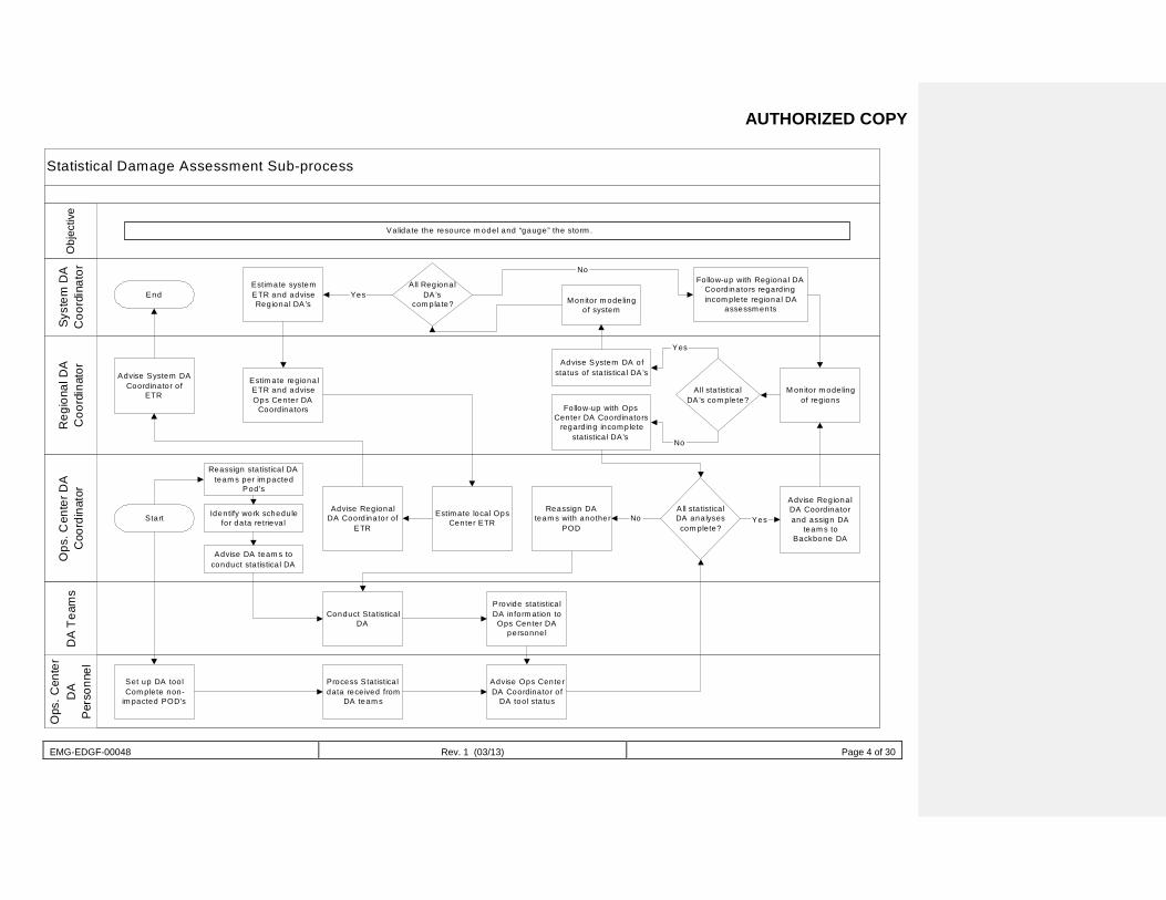
AUTHORIZED COPY
EMG-EDGF-00048 Rev. 1 (03/13) Page 4 of 30
Statistical Damage Assessment Sub-process
Ops
. Cen
ter
DA
Per
sonn
el
Syst
em D
AC
oord
inat
orR
egio
nal D
AC
oord
inat
orO
ps. C
ente
r DA
Coo
rdin
a tor
DA
Tea
ms
Obj
ectiv
e
Va lidate the resource m odel and “gauge” the storm .
EndEstimate systemETR and adviseRegional DA’s
All RegionalDA’s
com plate? Monitor m odelingof system
Follow-up with Regional DACoord inators regard ingincom plete reg ional DA
assessm ents
Advise System DACoord inator o f
ETR
Estim ate reg ionalETR and adviseOps Center DA
Coord inators
Advise System DA ofsta tus of sta tistica l DA’s
Follow-up with OpsCenter DA Coord inators
regard ing incompletestatistica l DA’s
All sta tisticalDA’s com plete?
M onitor m odelingof reg ions
Start
Reassign sta tistica l DAteam s per im pacted
Pod’s
Advise DA team s toconduct sta tistica l DA
Identify work schedulefor data re trieva l
Advise RegionalDA Coord inator of
ETR
Estimate loca l OpsCenter ETR
Advise RegionalDA Coord inatorand assign DA
team s toBackbone DA
All sta tistica lDA analysescom plete?
Reassign DAteam s with another
POD
Conduct Statistica lDA
Provide statistica lDA in form ation to
Ops Center DApersonnel
Set up DA too lCom plete non-
im pacted POD’s
Process Statistica ldata rece ived from
DA team s
Advise Ops CenterDA Coordinator o f
DA too l sta tus
No Yes
No
Yes
Yes
No
AUTHORIZED COPY
EMG-EDGF-00048 Rev. 1 (03/13) Page 5 of 30
Backbone Assessment This sub-process provides data for restoring the ‘backbone’ of the distribution systems, models TCA/OMS, and determines the number of customers who are out of service.
The following personnel are engaged in Backbone Assessment: Damage Assessor Support (DA2A1A) Damage Assessor (DA2A1) Operations Center Damage Assessment Coordinator (DA2A) Zone Damage Assessment Coordinator (DA2) System Damage Assessment Coordinator (DA1)
The flowchart below provides a detailed view of this sub-process:
Comment [ES3]: Change from “Electrical Sweep” to “Backbone Assessment”
Comment [ES4]: Change from “Electrical Sweep” to “Backbone Assessment”
Comment [ES5]: Change title from “Electrical Sweep Sub-Process” to “Backbone Damage Assessment Sub-Process”
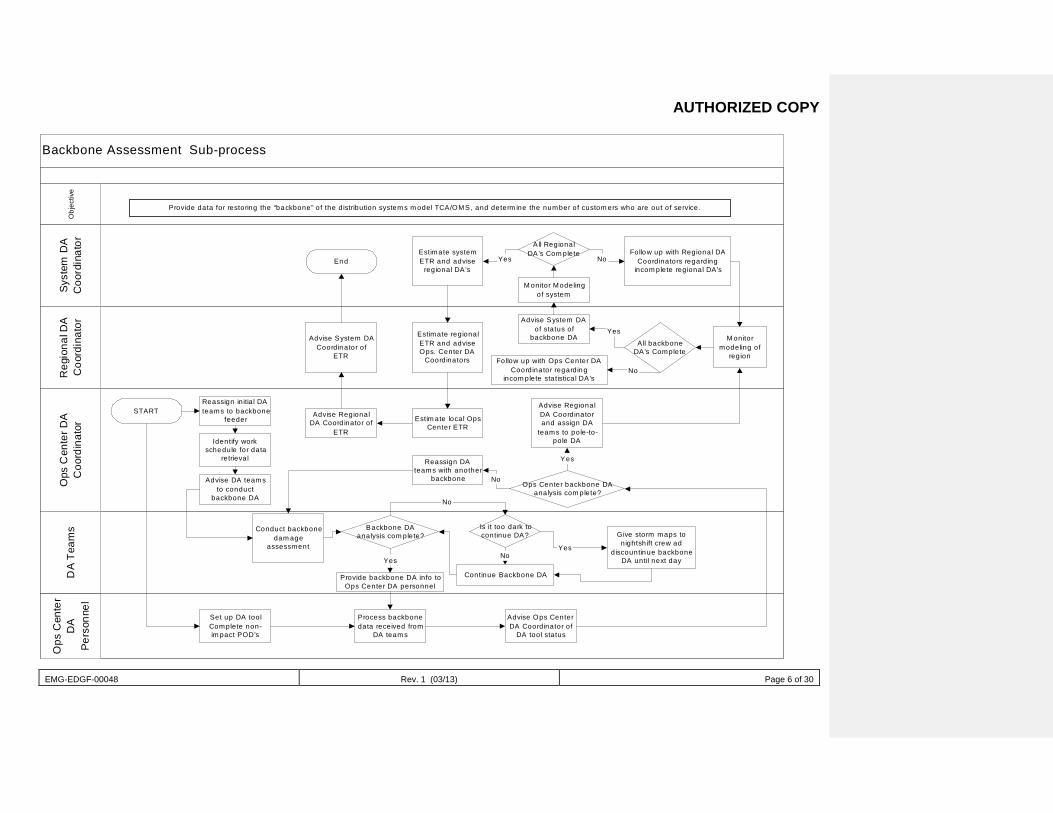
AUTHORIZED COPY
EMG-EDGF-00048 Rev. 1 (03/13) Page 6 of 30
Backbone Assessment Sub-process
Ops
Cen
ter
DA
Pers
onne
l
Syst
em D
AC
oord
inat
orR
egio
nal D
AC
oord
inat
orO
ps C
ente
r DA
Coo
rdin
ator
DA
Team
sO
bjec
tive
EndEstimate systemETR and advise
regional DA’s
A ll RegionalDA ’s Com plete
M onitor Modelingof system
Follow up with Regional DACoordinators regarding
incom plete regional DA’s
Advise System DACoordinator of
ETR
Reassign in itia l DAteams to backbone
feederSTART
Advise DA teamsto conduct
backbone DA
Identify workschedule for data
retrieval
Advise RegionalDA Coord inator of
ETR
Estimate regionalETR and adviseOps. Center DA
Coordinators
Estim ate local OpsCenter ETR
Reassign DAteams with another
backbone
Advise System DAof status of
backbone DA
Follow up with Ops Center DACoordinator regarding
incom plete statistical DA’s
A ll backboneDA’s Complete
M onitormodeling of
region
Conduct backbonedam age
assessment
Backbone DAanalysis com plete?
Provide backbone DA info toOps Center DA personnel
Is it too dark tocontinue DA?
Continue Backbone DA
Advise RegionalDA Coordinatorand assign DA
teams to pole-to-pole DA
Ops Center backbone DAanalysis com plete?
Set up DA toolComplete non-im pact POD’s
Process backbonedata received from
DA team s
Advise Ops CenterDA Coordinator of
DA tool status
Give storm maps tonightsh ift crew ad
discountinue backboneDA until next day
Yes
Yes
No
No
Yes
No
Yes
No
NoYes
Provide data for restoring the “backbone” of the distribution system s m odel TCA/OMS, and determ ine the number of custom ers who are out of service.
AUTHORIZED COPY
EMG-EDGF-00048 Rev. 1 (03/13) Page 7 of 30
Pole to Pole Damage Assessment This sub-process determines the location and nature of damage, develops crew work plans, models trouble call analysis (TCA) and outage management system (OMS), and develops estimated times of restoration by feeder.
The following personnel are engaged in Pole to Pole Damage Assessment: Damage Assessor Support (DA2A1A) Damage Assessor (DA2A1) Operations Center Damage Assessment Coordinator (DA2A) Zone Damage Assessment Coordinator (DA2) System Damage Assessment Coordinator (DA1) Environmental Lead (DA/ENV1)
The flowchart below provides a detailed view of this sub-process:
Comment [ES6]: Change from “Full Damage Assessment” to “Pole-to-Pole Damage Assessment”
Comment [ES7]: Change from “Full Damage Assessment” to “Pole-to-Pole Damage Assessment”
Comment [ES8]: Change title of flowchart from “Full Damage Assessment Sub-Process” to “Pole-to-Pole Damage Assessment Sub-Process”
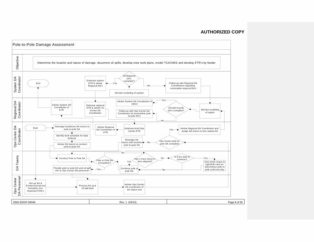
AUTHORIZED COPY
EMG-EDGF-00048 Rev. 1 (03/13) Page 8 of 30
Pole-to-Pole Damage Assessment
Ops
Cen
ter
DA
Per
sonn
elS
yst e
m D
AC
oord
inat
orR
egio
nal D
AC
oord
inat
orO
ps C
ente
r D
AC
oord
inat
orD
A T
eam
sO
bjec
tive
Determine the location and nature of damage, document oil spills, develop crew work plans, model TCA/OMS and develop ETR’s by feeder
EndEstimate system
ETR & adviseRegional DA’s
All RegionalDA’s
complete?
Monitor modeling of system
Follow-up with Regional DACoordinators regarding
incomplete regional DA’s
Monitor modelingof region
All pole-to-poleDA’s complete?
Advise System DA Coordinator ofstatus
Follow-up with Ops Center DACoordinator for incomplete pole-
to-pole DA’s
Estimate regionalETR & advise Os
Center DACoordinator
Advise System DACoordinator of
ETR
StartReassign backbone DA teams to
pole-to-pole DA
Identify work schedule for dataretrieval
Advise DA teams to conductpole-to-pole DA
Advise RegionalDA Coordinator of
ETR
Estimate local OpsCenter ETR
Advise Regional DA Coordinator andassign DA teams to tree sweep DA
Ops Center pole-to-pole DA complete/
Reassign DAteams with another
pole-to-pole DA
Conduct Pole to Pole DA
Provide pole to pole DA and oil spillinfo to Ops Center DA personnel
Pole to Pole DACompletee?
Has 4 hour check intime elapsed?
Is it too dark tocontinue?
Continue pole topole DA
Give storm maps tonightshift crew andiscontinue pole topole until next day
Set up DA &Environmental tool
Complete non-impacted POD’s
Process DA andoil spill data
Advise Ops CenterDA coordinator of
DA status tool
Yes
No
Yes
No Yes
No
Yes
Yes
No
No
YesNo
AUTHORIZED COPY
EMG-EDGF-00048 Rev. 1 (03/13) Page 9 of 30
Tree Sweep This sub-process mitigates post-storm, tree-caused outages by removing damaged limbs and trees that have not caused an outage during the event but have the potential to do so afterwards.
The following personnel are engaged in Tree Sweep: Business Operations Foresters Inspector System Damage Assessment Coordinator (DA1)
The flowcharts below provide a detailed view of this sub-process:
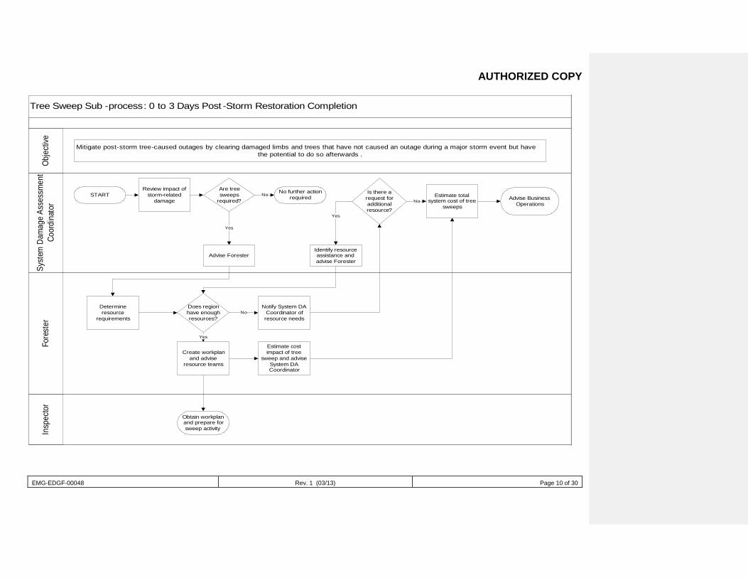
AUTHORIZED COPY
EMG-EDGF-00048 Rev. 1 (03/13) Page 10 of 30
Tree Sweep Sub -process: 0 to 3 Days Post -Storm Restoration Completion
Syst
em D
amag
e As
sess
men
t Co
ordi
nato
rFo
rest
erIn
spec
tor
Obje
ctive
Mitigate post-storm tree-caused outages by clearing damaged limbs and trees that have not caused an outage during a major storm event but have the potential to do so afterwards .
STARTReview impact of
storm-related damage
Are tree sweeps
required?
No further action requiredNo
Advise Forester
Yes
Determine resource
requirements
Does region have enough resources?
Notify System DA Coordinator of resource needs
Create workplan and advise
resource teams
Obtain workplan and prepare for sweep activity
Yes
No
Estimate cost impact of tree
sweep and advise System DA Coordinator
Is there a request for additional resource?
Estimate total system cost of tree
sweepsNo
Identify resource assistance and advise Forester
Yes
Advise Business Operations
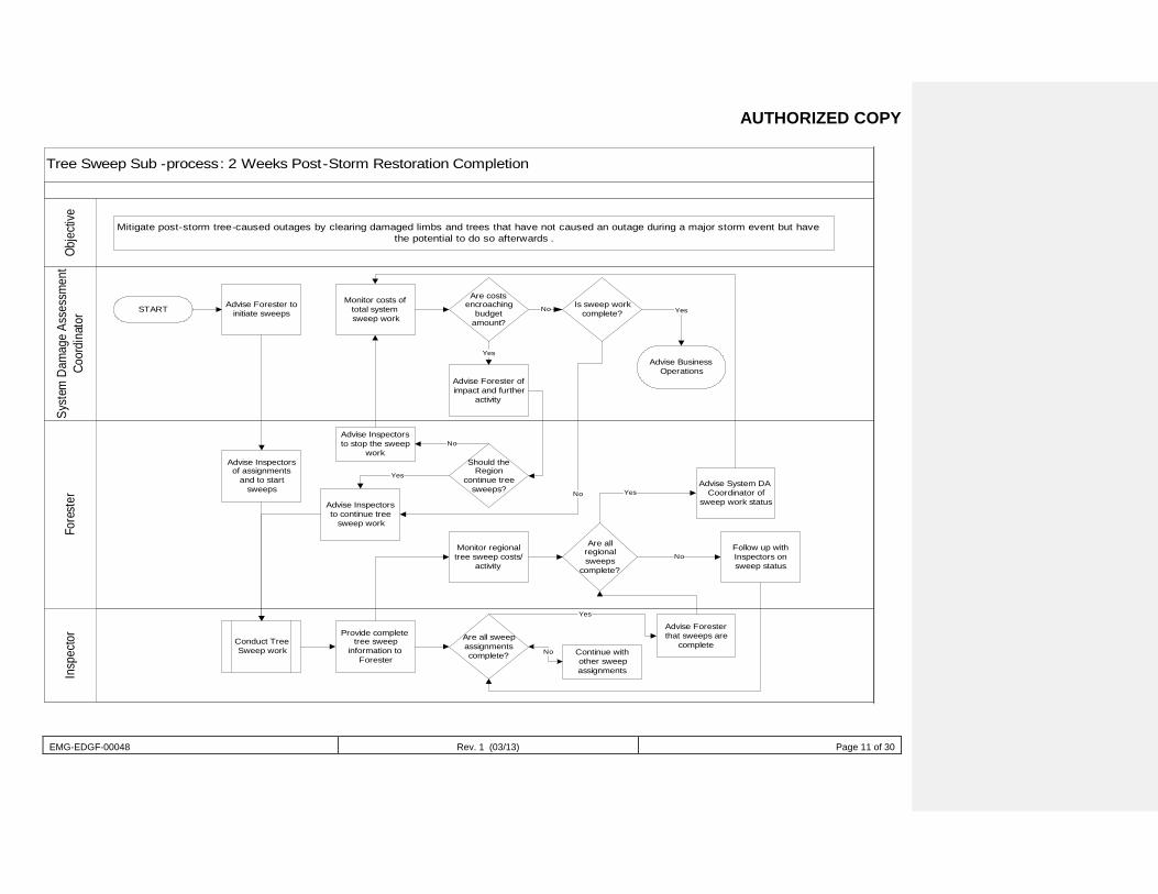
AUTHORIZED COPY
EMG-EDGF-00048 Rev. 1 (03/13) Page 11 of 30
Tree Sweep Sub -process: 2 Weeks Post-Storm Restoration Completion
Syst
em D
amag
e As
sess
men
t Co
ordi
nato
rFo
rest
erIn
spec
tor
Obje
ctive
Mitigate post-storm tree-caused outages by clearing damaged limbs and trees that have not caused an outage during a major storm event but have the potential to do so afterwards .
START Advise Forester to initiate sweeps
Monitor costs of total system sweep work
Are costs encroaching
budget amount?
Is sweep work complete?
Advise Business Operations
Yes
Advise Forester of impact and further
activity
Yes
No
Advise Inspectors of assignments
and to start sweeps
Conduct Tree Sweep work
Provide complete tree sweep
information to Forester
Advise Inspectors to continue tree
sweep work
Should the Region
continue tree sweeps?
No
Yes
Monitor regional tree sweep costs/
activity
Are all sweep assignments complete? Continue with
other sweep assignments
Advise Forester that sweeps are
completeNo
Yes
Are all regional sweeps
complete?
Advise System DA Coordinator of
sweep work status
Follow up with Inspectors on sweep status
No
Yes
Advise Inspectors to stop the sweep
work
No
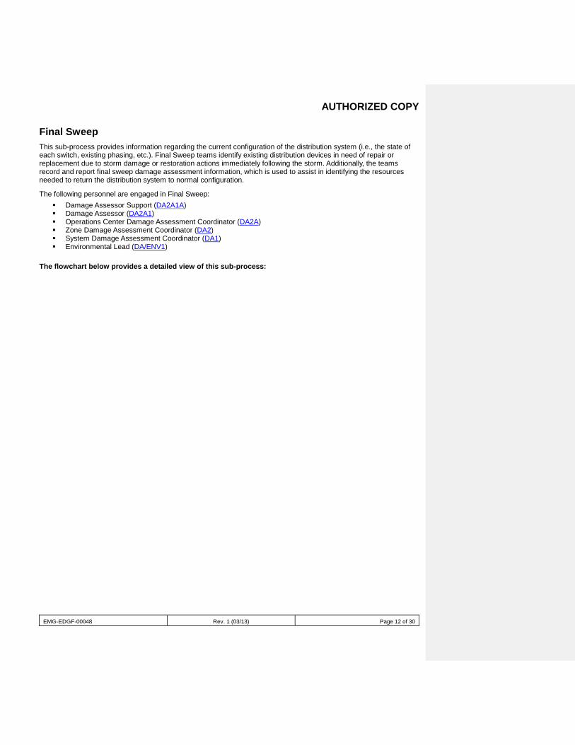
AUTHORIZED COPY
EMG-EDGF-00048 Rev. 1 (03/13) Page 12 of 30
Final Sweep This sub-process provides information regarding the current configuration of the distribution system (i.e., the state of each switch, existing phasing, etc.). Final Sweep teams identify existing distribution devices in need of repair or replacement due to storm damage or restoration actions immediately following the storm. Additionally, the teams record and report final sweep damage assessment information, which is used to assist in identifying the resources needed to return the distribution system to normal configuration.
The following personnel are engaged in Final Sweep: Damage Assessor Support (DA2A1A) Damage Assessor (DA2A1) Operations Center Damage Assessment Coordinator (DA2A) Zone Damage Assessment Coordinator (DA2) System Damage Assessment Coordinator (DA1) Environmental Lead (DA/ENV1)
The flowchart below provides a detailed view of this sub-process:
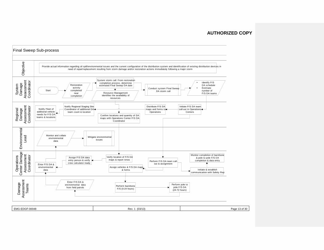
AUTHORIZED COPY
EMG-EDGF-00048 Rev. 1 (03/13) Page 13 of 30
Final Sweep Sub-process
Env
ironm
enta
lLe
ad
Syst
emD
amag
eAs
sess
men
tC
oord
inat
or
Reg
iona
lD
amag
eAs
sess
men
tCo
ordi
nato
r
Ope
ratio
nsC
ente
r Dam
age
Asse
ssm
ent
Coor
dina
tor
Dam
age
Asse
ssm
ent
Team
sO
bjec
tive
Provide actual information regarding oil spill/environmental issues and the current configuration of the distribution system and identification of existing distribution devices inneed of repair/replacement resulting from storm damage and/or restoration actions immediately following a major storm
Start
Restorationactivity
completed/near
completion
System storm call: From restorationcompletion process, determineestimated Final Sweep DA date
Resource Managementidentifies the availability of
resources
Conduct system Final SweepDA storm call
Identify F/SDA schedule
Estimatenumber ofF/S DA teams
Initiate F/S DA teamcall-out in Operations
Centers
Distribute F/S DAmaps and forms to
OperationsConfirm locations and quantity of DAmaps with Operations Center F/S DA
Coordinator
Notify Regional Staging SiteCoordinator of additional DA
team count & locationNotify Fleet of
additional vehicleneeds for F/S DAteams & locations
Verify location of F/S DAmaps & report times
Assign F/S DA dataentry person & verifycrew calculator readyEnter F/S DA &
environmentaldata
Assign vehicles & F/S DA maps& forms
Perform F/S DA team call-out & assignment
Monitor completion of backbone& pole to pole F/S DA
completion & data entry
Initiate & establishcommunication with Safety Rep
Perform backboneF/S (0-24 hours)
Enter F/S DA &environmental data
from field patrolsPerform pole to
pole F/S DA(24-72 hours)
Monitor and collateenvironmental
data
Mitigate environmentalissues
AUTHORIZED COPY
EMG-EDGF-00048 Rev. 1 (03/13) Page 14 of 30
Forensic Assessment This sub-process is not directly related to the restoration effort. The purpose of forensic assessment is to provide data on causal modes for distribution pole and structure damage due to storm related damage. The following personnel are engaged in Final Sweep:
System Damage Assessment Manager (DA1)
System Forensic Coordinator (DA3)
Zone Forensic Lead (DA3A)
Forensic Assessor(DA3A1)
The flowchart below provides a detailed view of this sub-process: Comment [ES9]: Who is the System Forensic Coordinator? If this is the same a the System DA Coordinator, lets stay consistent and keep the identical title of System DA Coord. Who is the Zone Forensic Lead? If this is the same the Zone DA Coordinator, lets stay consistent and keep the identical title of Zone DA Coord. Who is the Forensic Assessor/Support?
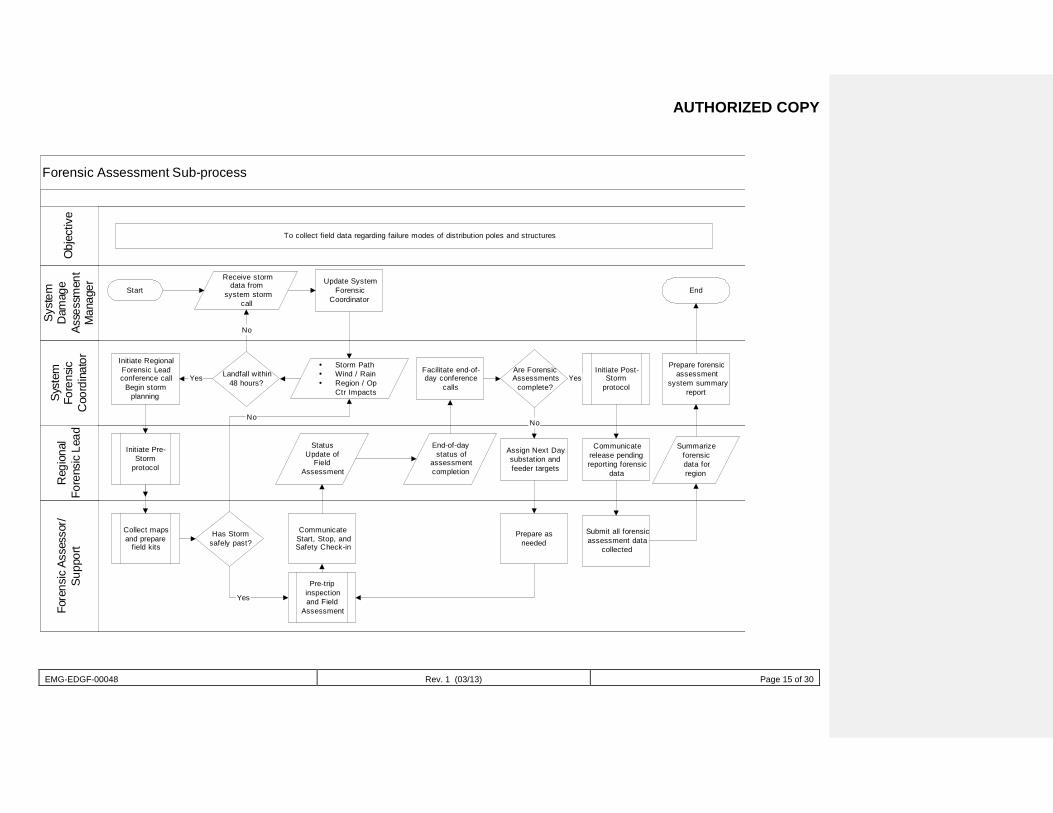
AUTHORIZED COPY
EMG-EDGF-00048 Rev. 1 (03/13) Page 15 of 30
Forensic Assessment Sub-process
Syst
emD
amag
eAs
sess
men
tM
anag
er
Syst
emFo
rens
icC
oord
inat
or
Reg
iona
lFo
rens
ic L
ead
Fore
nsic
Ass
esso
r/Su
ppor
tO
bjec
tive
To collect field data regarding failure modes of distribution poles and structures
Start
Receive stormdata from
system stormcall
Update SystemForensic
Coordinator
Initiate RegionalForensic Leadconference call
Begin stormplanning
Has Stormsafely past?
No
Collect mapsand prepare
field kits
Yes
Facilitate end-of-day conference
calls
CommunicateStart, Stop, andSafety Check-in
StatusUpdate of
FieldAssessment
Are ForensicAssessments
complete?
End-of-daystatus of
assessmentcompletion
End
Storm Path Wind / Rain Region / Op
Ctr Impacts
Landfall within48 hours?
No
Yes
Initiate Pre-Storm
protocol
Pre-tripinspectionand Field
Assessment
Initiate Post-Storm
protocolYes
Communicaterelease pendingreporting forensic
data
Assign Next Daysubstation andfeeder targets
No
Prepare asneeded
Submit all forensicassessment data
collected
Summarizeforensicdata forregion
Prepare forensicassessment
system summaryreport
AUTHORIZED COPY
EMG-EDGF-00048 Rev. 1 (03/13) Page 16 of 30
Job Descriptions (DA1-DA3)
DA1: System Damage Assessment Coordinator
Job Function
The System Damage Assessment Coordinator is responsible for the overall readiness of the damage assessment process at Duke Energy FL and provides leadership to the process.
Job Description Understand the DSSOP and Damage Assessment Storm Plan and communicate effectively across group and
department lines, ensuring that the damage assessment process is properly aligned with storm restoration strategy
Maintain relationships with field and storm management team members Lead lessons learned activities following major events to ensure continual improvement
Key Interface Points Distribution System Storm Coordinator (DSSC1) Operations Center Damage Assessment Coordinator (DA3) Zone Damage Assessment Coordinator (DA2)
Checklist of Actions
Before Major Storm Recruit skilled (senior) and unskilled Damage Assessors (DA2A1) (DA2A1A) from:
Zone/Operations Center personnel RSVP volunteers Retirees Fossil and Nuclear plants Transmission Department Contractors
Create and maintain Damage Assessment databases and distribution lists Develop, schedule, and deliver Damage Assessor (DA2A1) training Develop and schedule training for Zone and local Operations Center Damage Assessment contacts Ensure that estimated time of restoration (ETR) tool is maintained and enhanced to meet restoration needs Participate in development and administering of system storm drills to ensure readiness Develop and maintain specifications for statistical and feeder maps utilized during the Damage Assessment
process Communicate vehicle needs to Service Company/Transportation personnel, and work with vendors to ensure
that storm deliverables can be met Determine Damage Assessment materials needs, secure funding, purchase, and distribute to Duke FL and
other jurisdictions
During Major Storm Participate in all System storm conference calls to develop restoration strategy Develop Damage Assessment plan and deploy to the field Determine availability of Damage Assessment team members E-mail team member names and contact information to distribution lists Direct phone calls to Damage Assessment team members Develop Damage Assessment team assignments and vehicle deployment plans Deploy and communicate Damage Assessment plan to Zone Damage Assessment Coordinator (DA2) Monitor storm progress and make Damage Assessment adjustments as necessary Monitor data entry into ETR tool across the System Provide resource modeling and ETR estimates for the System to the Distribution System Storm Coordinator
(DSSC1)
AUTHORIZED COPY
EMG-EDGF-00048 Rev. 1 (03/13) Page 17 of 30
After Major Storm Demobilize deployed Damage Assessment teams Process billing and invoices for retirees and contractors Lead lessons learned activities Provide input into DSSOP improvement Refurbish Damage Assessment kit materials
Training Requirements
Before Major Storm Review DSSOP and recent lessons learned to ensure understanding of “the big picture” as it pertains to
damage assessment, restoration, and customer communications Participate in developing storm drill scenarios to ensure readiness of all those involved in the damage
assessment process Communicate with Human Resources to obtain lists of recent retirees for recruiting purposes Review and test tools to ensure workability and competency of users: Resource Tracking, Damage
Assessment Data Entry, Damage Assessment ETR (Web-based) Review Damage Assessment training module for potential enhancements Develop and implement Damage Assessment training classes for newly recruited Damage Assessors
(DA2A1) and contractors Communicate with Damage Assessors (DA2A1) to enlist support for upcoming storm season
Event Promotion Success Factors Coordination with corporate storm team to ensure awareness of the damage assessment process and
requirements Coordination and linkage with Zone Damage Assessment Coordinators (DA2) and Operations Center Damage
Assessment Coordinators (DA2A) to ensure an overall understanding of the damage assessment process, and to make sure that needed maps are in place, Damage Assessment Data Entry and ETR tools are functional, and Damage Assessment resource-sharing capability is available
Awareness of storm conference call schedule (all processes) Coordination with Transmission Department storm team for potential helicopter resources
Engaged in the Following Sub-processes Predictive Modeling Statistical Damage Assessment Pole to Pole Damage Assessment Backbone Assessment Tree Sweep Final Sweep Estimated Time of Restoration Management Forensic Assessment Comment [ES10]: Relocate prior to the
“Statistical Damage Assessment” listing above.
AUTHORIZED COPY
EMG-EDGF-00048 Rev. 1 (03/13) Page 18 of 30
DA2: Zone Damage Assessment Coordinator
Job Function
The Zone Damage Assessment Coordinator is responsible for the overall readiness of the damage assessment process within the assigned Zone and provides leadership to the process.
Job Description Understand the Damage Assessment Storm Plan and communicate effectively across the Zone to ensure that
the damage assessment process is in a ready state Communicate with the System Damage Assessment Coordinator (DA1) to ensure linkage with the DSSOP Participate in lessons learned activities following major events to ensure continual improvement
Key Interface Points Operations Center Damage Assessment Coordinators (DA2A) Zone Storm Coordinator (REG2) System Damage Assessment Coordinator (DA1)
Checklist of Actions
Before Major Storm Organize and participate in training of Operations Center Damage Assessment personnel Stay linked with System Damage Assessment Coordinator (DA1) to ensure readiness Ensure that all Operations Center contacts have the current ETR tool and are trained in its use Ensure that all Damage Assessment kits in Operations Centers are current Ensure that Zone GIS Coordinators provide resources for timely printing of feeder maps and statistical
maps for damage assessment Work with Zone management (REG1 and REG2) to ensure resource-sharing capability in the event the
Zone is not impacted by a storm (i.e., how many Damage Assessment teams can be made available elsewhere)
During Major Storm Participate in Zone storm conference calls Communicate with System Damage Assessment Coordinator (DA1) to ensure that the deployment plan is
understood Monitor storm progress and make Damage Assessment adjustments as necessary Monitor ETR tool for data input Duke and maintain communications with Operations Center Damage
Assessment contacts to ensure that data flow is timely Provide Zone resource modeling from statistical damage assessment data If Zone is not impacted by storm, engage Zone Damage Assessment Coordinator (DA2) to develop a
Damage Assessment resource-sharing plan for use elsewhere in the System
After Major Storm Participate in demobilizing efforts once restoration is complete Participate in lessons learned activities Provide support to System Damage Assessment Coordinator (DA1) to determine refurbishing materials
for Damage Assessment kits Ensure that Operations Center feeder maps and statistical sampling maps get restocked for next storm
AUTHORIZED COPY
EMG-EDGF-00048 Rev. 1 (03/13) Page 19 of 30
Training Requirements
Before Major Storm Review Zone Storm Plan and recent lessons learned to ensure understanding of “the big picture” as it
pertains to damage assessment, restoration, and customer communications Review and test tools to ensure workability and competency of users: Resource Tracking, Damage
Assessment Data Entry, and Damage Assessment ETR (Web-based) Provide the DA training/safety awareness presentation at the DA staging sites prior to dispatching DA
teams
Event Promotion Success Factors Coordination with Zone storm team to ensure awareness of the damage assessment process, requirements,
and resource-sharing capability in the event the Zone is not impacted by a major storm (i.e., how many Damage Assessment teams can be supplied to the DSSC)
Coordination and linkage with System Damage Assessment Coordinator (DA1) and Operations Center Damage Assessment Coordinators (DA2A) to ensure overall understanding of damage assessment process and readiness (maps in place, Damage Assessment Data Entry and ETR tools functional, etc.)
Awareness of Zone storm conference call schedule Promoting safety!!!
Engaged in the Following Sub-processes Pole Forensic Damage Assessment Statistical Damage Assessment Backbone Assessment Pole to Pole Damage Assessment Final Sweep
DA2A: Operations Center Damage Assessment Coordinator
Job Function
The Operations Center Damage Assessment Coordinator is responsible for the overall readiness of the damage assessment process within the assigned Operations Center.
Job Description Understand the Damage Assessment Storm Plan and communicate effectively within the Operations Center to
ensure that the damage assessment process is in a ready state Communicate with Zone Damage Assessment Coordinator (DA2) to ensure linkage with the DSSOP Participate in lessons learned activities following major events to ensure continual improvement
Key Interface Points Operations Center storm team Zone Damage Assessment Coordinator (DA2) System Damage Assessment Coordinator (DA1)
Checklist of Actions
Before Major Storm Participate in training of Operations Center Damage Assessment personnel Stay linked with Zone Damage Assessment Coordinator (DA2) to ensure readiness Ensure that the most current version of the ETR tool is on appropriate Operations Center computers and
that designated personnel are trained in its use Maintain Damage Assessment kits in the Operations Center and provide local maps as needed Ensure that adequate feeder and statistical maps are available for Damage Assessment use Provide directions and addresses to beginning points of all statistical sampling maps
Comment [ES11]: Add: Provide the DA Training/Safety Awareness presentation at the DA staging sites prior to dispatching DA teams
Comment [ES12]: Add the “Pole Forensic Damage Assessment” listing.
AUTHORIZED COPY
EMG-EDGF-00048 Rev. 1 (03/13) Page 20 of 30
During Major Storm Communicate with Zone Damage Assessment Coordinator (DA2) to ensure that deployment plan is
understood Develop logistics and deploy Damage Assessment plan for the Operations Center Work with Damage Assessor (DA2A1) to provide refresher training to incoming teams Input statistical data into ETR tool, perform resource modeling for the Operations Center, and upload data
to server Input non-emergency environmental reports into environmental tool for tracking by the Zone
Environmental Lead (DA/ENV1) Input actual damage data into ETR tool to assist in developing feeder-level ETRs Provide feeder-level ETRs to Zone Damage Assessment Coordinator (DA2) for review prior to data
loading in Outage Management System (OMS) Ensure that Damage Assessment data and maps are provided to Feeder/Field Coordinators (OPS2C1A) Fax completed Actual Damage Assessment forms to Distribution Control Center (DCC) (fax # is on bottom
of form) for creation of outages in Trouble Call Analysis (TCA) Ensure a smooth transition for Damage Assessment teams—from performing damage assessment to
leading crews, running Outage Tickets, etc. If Operations Center is not directly impacted by the storm, offer local resources to Zone Damage
Assessment Coordinator (DA2) for developing a resource-sharing plan
After Major Storm Participate in demobilization efforts once restoration is complete DA teams are released to the Zone
Damage Assessment Coordinator (DA2) Participate in lessons learned activities Survey Damage Assessment kits and provide list of needs to Zone Damage Assessment Coordinator
(DA2) Restock Operations Center feeder maps, statistical sampling maps, and local maps as needed
Training Requirements
Before Major Storm Review Operations Center Storm Plan and recent lessons learned to ensure understanding of “the big
picture” as it pertains to restoration and customer communications Review and test tools to ensure workability and competency of users: Resource Tracking, Damage
Assessment Data Entry, and Damage Assessment ETR (Web-based) Ensure the DA training/safety awareness presentation was conducted with all DA teams at the DA staging
sites prior to dispatching DA teams
Event Promotion Success Factors Coordination with Operations Center Resource Management Coordinator (OPS3) to ensure awareness of the
damage assessment process and requirements Coordination and linkage with System Damage Assessment Coordinator (DA1) and Zone Damage
Assessment Coordinator (DA2) to ensure overall readiness Ensuring that the following items are available: Damage Assessment statistical maps, multiple copies (five
recommended) of feeder maps, Damage Assessment kits, and local maps
Engaged in the Following Sub-processes Statistical Damage Assessment Backbone Assessment Pole to Pole Damage Assessment Final Sweep Estimated Time of Restoration Management
Comment [ES13]: Add: Ensure the DA Training/Safety Awareness presentation was conducted with all DA teams at the DA staging sites prior to dispatching DA teams
AUTHORIZED COPY
EMG-EDGF-00048 Rev. 1 (03/13) Page 21 of 30
DA2A1: Damage Assessor
Job Function The Damage Assessor performs field damage assessments.
Job Description Understand the Damage Assessment Storm Plan and communicate effectively across the Zone to ensure that
the damage assessment process is in a ready state Oversee Damage Assessment teams, making sure that they are properly prepared, equipped, and housed Conduct refresher and safety trainings with Damage Assessment teams Track Duke of damage assessment work and move resources as needed Communicate with the System Damage Assessment Coordinator (DA1) to ensure linkage with the DSSOP
Key Interface Points Feeder/Field Coordinators (OPS2C1A) Operations Center Damage Assessment Coordinators (DA2A) System Damage Assessment Coordinator (DA1)
Checklist of Actions
Before Major Storm Attend Damage Assessment briefing to get assignment, team information, and up-to-date weather update Attend pre-storm season training to ensure familiarity with: Damage assessment process, forms, etc. ETR tool review Maps to Operations Centers and staging sites
During Major Storm
Before traveling to location: Access Storm Center Website (“Current Information”) and print Damage Assessment assignment
document. Download current Distribution Information System (DIS) Field View data for assigned area (optional) Notify assigned Operations Center of schedule, estimated time of arrival of teams, and preparations
needed prior to arrival (vehicle assignment, etc.) Determine whether the Operations Center has resource needs (Network routers, office supplies, hardhats,
etc.)
Before storm, after arriving at assigned location: Review skill level of assigned Damage Assessment team members Access Storm Center Website (“Current Information”), and print copy of most current Damage
Assessment assignment document and other information, and provide to Damage Assessment tea members
Ensure that Damage Assessment vehicles are in place and obtain keys Record vehicle and tag information for each assigned vehicle Remind Damage Assessment team members to return vehicles to point of origin
Provide “just in time” Damage Assessment refresher training to all Damage Assessment teams immediately prior to major storm event. Suggested meeting format:
Briefly cover “Damage Assessment Why Do It?” and “Damage Assessment Requirements” slides
AUTHORIZED COPY
EMG-EDGF-00048 Rev. 1 (03/13) Page 22 of 30
Hand out color copies of the following slides and discuss: Damage Assessment Color Coding DIS Feeder Maps Statistical Damage Assessment Form Example Damage Assessment Scenario #1 (with damage data, no color coding) Damage Assessment Data Form Scenario #1 (completed) Damage Assessment Scenario #1 (final) Damage Assessment Scenario #2 (final) Damage Assessment Data Form Scenario #2 Damage Assessment Scenario #3 (final) Damage Assessment Data Form Scenario #3 Wrap up with reminders from the Personal Safety and Vehicle Safety slides
Ensure that all Damage Assessment teams have the following items (one per team): Damage Assessment bag
Strobe light Hand-held light (red “Show Me” light with 12v charger, fully charged) Flood light Supply of Damage Assessment forms (10 copies statistical and 25 copies pole-to-pole) Local road maps Emergency numbers Damage Assessment team member contact numbers Hand-held radios (if Operations Center has them available for Damage Assessment use) Operations Center contact numbers
(NOTE: All of these materials are located at each Operations Center and can be obtained from the local Administrative Support or Damage Assessment contact)
Coordinate with Operations Center Damage Assessment contact to: Locate statistical grid, distribution feeder, and local maps Organize statistical assessment and assign Damage Assessment teams Define the backbone for each feeder Utilize statistical assessment data and TCA data to determine when/if backbone assessments will
begin and where Organize runners (where needed) and meeting times with Damage Assessment teams Assign vehicles to Damage Assessment teams Ensure that extra Damage Assessment forms are available Review faxing procedure for backbone and pole-to-pole Damage Assessment forms to Customer
Service Center Ensure that backbone and pole-to-pole data are entered into ETR tool by Operations Center staff
After Major Storm Before beginning damage assessment:
Access Storm Center Website (“Current Information”), print copy of most current Damage Assessment assignment document and current weather forecast, and provide to team members
Conduct pre-job safety briefing, sharing field conditions and safety pointers Continue to emphasize working safely in hazardous situations Obtain information about housing and food arrangements and ensure that Damage Assessment teams
are in the loop Ensure pre-trip inspections are performed on vehicle
During damage assessment and restoration phase: Lead pre-job briefings prior to each assessment Track Duke of work and move resources as needed Record non-emergency oil spills and environmental issues Emergency oil spills shall be immediately reported to the Zone Environmental Lead (DA/ENV1) Ensure that color-coded feeder maps are given to Feeder/Field Coordinators (OPS2C1A) Ensure that backbone and pole-to-pole data are entered into ETR tool
AUTHORIZED COPY
EMG-EDGF-00048 Rev. 1 (03/13) Page 23 of 30
After completion of restoration work: Document:
Follow-up work for crews Transformers and poles left in field Oil spills requiring clean-up
Ensure that Damage Assessment teams return all Damage Assessment kits, lights, rental vehicles and keys, and associated items to the Operations Center when released
If Damage Assessment teams are relocated to other Operations Centers, where the total number of Damage Assessment teams deployed exceeds the set number for the Operations Center, ensure that teams carry Damage Assessment kits with them
Ensure that Damage Assessment kits are returned to the Operations Center of origin
Training Requirements Review Damage Assessment training materials Arrange to attend a Damage Assessment training class if not trained or if not deployed as a Damage Assessor
in the last three years Communicate any changes in contact numbers (home, work, cell phone, e-mail address, etc.) to System
Damage Assessment Coordinator (DA1) Keep abreast of major weather developments and proactively contact System Damage Assessment
Coordinator (DA1) regarding availability
Engaged in the Following Sub-processes: Statistical Damage Assessment Backbone Assessment Pole to Pole Damage Assessment Final Sweep Estimated Time of Restoration Management
DA2A1A: Damage Assessor Support Job Function
This position is typically filled by personnel with no experience in distribution or transmission systems. This position will work with the Damage Assessor.
Job Description
This position is primarily responsible for:
the safe operation of the patrol vehicle
entering damage assessment data that Damage Assessor has identified
performing pre-flight inspections of vehicle
participate in pre-job briefings prior to each assessment
AUTHORIZED COPY
EMG-EDGF-00048 Rev. 1 (03/13) Page 24 of 30
DA3: System Forensic Assessment Coordinator Job Function This position is responsible for the coordination of collecting and collating forensic data of distribution pole and structure damage due to a major storm. Job Description This position will:
• Monitor path of approaching storm coordinate a pre-storm conference call with Zone Forensic Leads at least 48 hours prior to expected landfall.
• Facilitate and document substation and feeder assignments among Zone Forensic Leads • Coordinate end-of-day conference calls with Zone Forensic Leads to determine daily Duke and communicate
system forensic assignments for the following day. • Develop and deliver post-storm System Forensic Summary Report to the Damage Assessment Manager
within 2 weeks after storm restoration activity has been completed. Key Interface Points System Damage Assessment Coordinator (DA1) Zone Forensic Lead (DA3A) Checklist of Actions Before Major Storms
• Validate Forensic Assessment roles have been assigned and filled for all Zones • Ensure that training modules are updated annually • Ensure Forensic Team is trained prior to storm season • Monitor path of approaching storm and coordinate pre-storm conference call with Zone Forensic Leads at
least 48 hours prior to expected landfall to document initial substation and feeder assignments. During Major Storm
• Facilitate end-of-day conference calls with Zone Forensic Leads to document the status of substation and feeder assignments and coordinate next day assignments
• Collect and collate all forensic data After Major Storm
• Develop and deliver post-storm System Forensic Summary Report to the Damage Assessment Manager within 2 weeks after storm restoration activity has been completed.
Engaged in the following Sub-process: Forensic Assessment
AUTHORIZED COPY
EMG-EDGF-00048 Rev. 1 (03/13) Page 25 of 30
DA3A: Zone Forensic Lead Job Function This position is responsible for the execution of a forensic review of the assigned Zone and for coordinating the field activities of the Forensic Assessors and Forensic Support functions. Job Description The Zone Forensic Lead will be responsible for identifying, recruiting, and training team members to perform Forensic Assessment. In addition, this position will:
• Participate in pre-storm conference call with System Forensic Coordinator at least 48 hours prior to expected landfall to determine high-priority substations for Forensic Assessment and additional calls, as needed.
• Communicate team assignments and expected initial reporting time/location to Forensic Assessor and Forensic Support team members 48 hours in advance of expected landfall
• Secure and assign vehicles for all Forensic Assessment teams within the Zone • Determine and communicate daily substation and feeder assignments by team • Establish protocols and timelines with Forensic Assessment teams within the Zone for communicating daily
start, stop, and safety check-in times and notify system Damage Assessment Manager and System Forensic Coordinator if communication is not established with teams as expected.
• Participate in end-of-day conference calls with System Forensic Coordinator and other Zone Forensic Leads to determine the system-wide status of Forensic Assessment and assign assessment locations for the following day
• Provide complete Zone Substation Forensic Summary Reports to System Forensic Coordinator within 1 week after storm restoration activity has been completed
Key Interface Points System Forensic Assessment Coordinator (DA3) Forensic Assessor (DA3A1) Forensic Support (DA3A1A) Checklist of Actions Before Major Storms
• Ensure Zone Forensic Assessment organization has been staffed and trained During Major Storm
• Pre-Storm Protocol Participate in pre-storm conference call with System Forensic Coordinator and other Zone Forensic
Leads at least 48 hours in advance of expected landfall to determine resource needs and potential Day 1 assessment locations by substation and feeder.
Communicate team assignments and expected initial reporting time/location to Forensic Assessor and Forensic Support team members 48 hours in advance of expected landfall
Secure 1 vehicle for each 2 person Forensic Assessment team expected for the Zone Provide final call to Forensic Assessor and Forensic Support team members 6 to 24 hours in advance
of expected landfall to confirm team assignment and substation feeder assignments. Establish protocols and timelines with Forensic Assessment teams within the Zone for communicating
daily start, stop, and safety check-in times and notify system Damage Assessment Manager and System Forensic Coordinator
• Obtain status report from Forensic Assessment teams prior to end-of-day conference call with System
Forensic Coordinator and other Zone Forensic Leads • Participate in end-of-day conference calls with System Forensic Coordinator and other Zone Forensic Leads
to determine the system-wide status of Forensic Assessment and assign assessment locations for the following day
AUTHORIZED COPY
EMG-EDGF-00048 Rev. 1 (03/13) Page 26 of 30
After Major Storm • Confirm vehicles have been returned • Provide complete Zone Substation Forensic Summary Reports to System Forensic Coordinator within 1 week
after storm restoration activity has been completed Engaged in the following Sub-process: Forensic Assessment
DA3A1: Forensic Assessor Job Function This position is primarily responsible for conducting a forensic review and the collection of data on the failure mode of distribution poles. Job Description The Forensic Assessor will be responsible for the resources necessary to conduct the Forensic Assessment in the field, including the direct supervision of an assigned Forensic Support team member. This position will:
• Be proficient in the data collection process and procedure necessary to conduct Forensic Assessment • Prepare field kit upon initial notification of assignment from Zone Forensic Lead (described below) • Confirm daily Forensic Assessment assignment with Zone Forensic Lead and confirm protocols and timelines
with for communicating daily start, stop, and safety check-in times • Initiate contact with assigned Forensic Support team member and provide just-in-time refresher of
expectations as required • Conduct pre-trip inspection with Forensic Support prior to departing local Operation Center to ensure all
materials and resources are available and that the vehicle is in safe working order • Conduct pre-job briefing before each inspection • Conduct field Forensic Assessment of assigned substations and/or feeders and collect required data for each
pole identified as damaged or in need of repair • Report daily observations and status update to Zone Forensic Lead as assigned • Complete and submit hardcopy checklist to Zone Forensic Lead for each pole identified as damaged or in
need of repair no later than 2 days after restoration activity has been completed Key Interface Points Zone Forensic Lead (DA3A) Forensic Support (DA3A1) Checklist of Actions Before Major Storms
• Be knowledgeable of the roles and responsibilities of the Forensic Assessor and Forensic Support functions, including the proper procedures for collecting data regarding the failure mode of distribution poles
• Be familiar with current Distribution Construction Specifications likely to be encountered during field Forensic Assessment of overhead distribution construction
• Ensure PPE is inspected and in date
AUTHORIZED COPY
EMG-EDGF-00048 Rev. 1 (03/13) Page 27 of 30
During Major Storm
• Print or collect current statistical grid, distribution feeder, and local road maps that correspond to assigned substations and/or feeders
• Prepare daily field kit to consist of at least: Strobe light Supply of Forensic Assessment Forms (sufficient number for assigned area) Emergency numbers Forensic Assessment team member contact numbers Local Operations Center contact numbers Water Personal items
• Have ready access to additional PPE for Forensic Support team member if needed • Initiate contact with assigned Forensic Support team member to confirm reporting location and time • Check-out vehicle • Conduct pre-job briefing with Forensic Support prior to departing local Operation Center to ensure all materials
and resources are available and are in safe working order • Communicate start, stop, and safety check-in times with Zone Forensic Lead as required • Facilitate safe navigation to and from Forensic Assessment locations • Conduct field Forensic Assessment of all assigned substations and/or feeder locations and ensure a Forensic
Assessment form has been completed with the required data for each pole identified as damaged or in need of repair
• Provide direction to and supervision of Forensic Support to facilitate efficient and safe collection of data • Report daily observations and status update to Zone Forensic Lead as assigned • Communicate daily assignments and meeting logistics information to assigned Forensic Support team
member After Major Storm
• Return vehicle • Complete and submit hardcopy checklist to Zone Forensic Lead for each pole identified as damaged or in
need of repair no later than 2 days after restoration activity has been completed Engaged in the following Sub-process: Forensic Assessment
DA3A1A: Forensic Support Job Function This position will provide field support to the Forensic Assessor in the collection of required data during Forensic Assessment in the field. Job Description This position is responsible for:
• Participating in pre-job briefings • Safe operation of assigned passenger vehicle • Cataloguing time, location, and other required data for each pole identified as damaged or in need of repair • Assisting in the preparation of summary reports for use by the Zone Forensic Lead
Key Interface Points Forensic Assessor Zone Forensic Lead
AUTHORIZED COPY
EMG-EDGF-00048 Rev. 1 (03/13) Page 28 of 30
Checklist of Actions Before Major Storms
• Review storm plan assignment • Ensure PPE is inspected and in date • If required, pack personal needs and clothing for extended period • Receive pre-storm planning communication from Zone Forensic Lead
During Major Storm • Arrive at assigned area with PPE and personal items • Check in with the Forensic Assessor • Assist Forensic Assessor with data collection • Assist Forensic Assessor with maintaining communication schedule during the shift • Assist Forensic Assessor with data download at the end of each shift • Assist in pre-trip inspection of vehicle • Participate in pre-job briefings prior to each assessment
After Major Storm
• Support Forensic Assessor as required in completing summary reports Engaged in the following Sub-process: Forensic Assessment
DA/ENV1: Environmental Lead
Job Function
The Environmental Lead is the primary contact at the Zone storm center for environmental response activities. This individual will coordinate environmental responses and address all environmental issues as part of the damage assessment and restoration processes.
Job Description Participate in Zone storm calls as necessary Ensure sufficient environmental resources are available Direct environmental resources for required response activities Interface with environmental regulatory agencies as necessary Provide updates and status of environmental response activities to appropriate Company management
Key Interface Points Zone Storm Center Transmission Storm Organization Operation Center Damage Assessment Coordinator (DA2A) Zone restoration personnel (emergency spills only)
Checklist of Actions
Before Major Storm Contact environmental emergency response contractors to provide notification of potential activation for storm
response support Review and, if needed, make arrangements for material needs for environmental response activities Arrange for additional environmental FTE support from the CAROLINA ZONE Environmental Support Group
and the PE Service Company Environmental Services Section
AUTHORIZED COPY
EMG-EDGF-00048 Rev. 1 (03/13) Page 29 of 30
During Major Storm Interface with Ops Center Damage Assessment Coordinators to identify non-emergency environmental events
requiring response (interface may be accomplished by use of electronic environmental tool) Monitor assigned Zone environmental updates from Ops Center DA Coordinators
Develop environmental response plan from this information Receive emergency environmental calls from field personnel and mitigate issues Oversee environmental response activities Interface with environmental regulatory agencies Provide internal communications/updates Coordinate environmental responses as part of DA sweeps
After Major Storm Coordinate collection and management of environmental data Ensure environmental issues are completed in a timely manner Ensure proper accounting and processing of environmental related storm costs Participate in lessons learned and process enhancement
Tools and Information Needed Damage assessment data
Internal and external communication ability
Environmental contact list
Environmental Response contractor list
Distribution and Transmission team contacts
Training Requirements Job related functions
DA/ENV1A: Environmental Support
Job Function The environmental support person will typically be in the field overseeing environmental response activities. This position will report to and follow the direction of the Environmental Lead. During periods where environmental response is not required, this position will provide, as needed, support to storm restoration activities. Job Description Direct environmental response contractors and other resources performing environmental response activities. Ensure sufficient environmental resources are available for each response need in coordination with the
Environmental Lead’s direction Interface with environmental regulatory agencies as necessary Provide updates and status of environmental response activities to Environmental Lead Direct environmental response activities during final storm sweeps
Key Interface Points Environmental Lead (DA/ENV1) Operation Center Storm Personnel Transmission Storm Personnel
AUTHORIZED COPY
EMG-EDGF-00048 Rev. 1 (03/13) Page 30 of 30
Systems For Damage Assessment Team
Damage Assessment online tool ETR online tool OMS Resource Tracking tool Environmental input tool
Supplemental Information
• DEF Line Contractor Crew Sheet
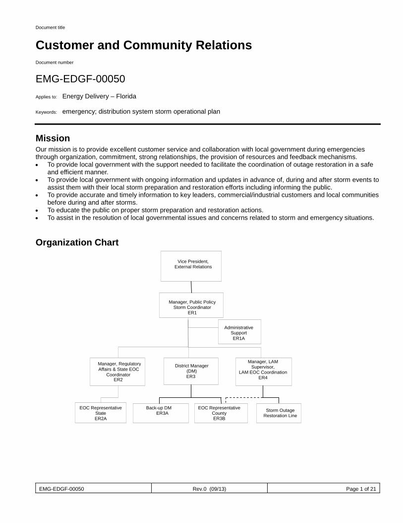
EMG-EDGF-00050 Rev.0 (09/13) Page 1 of 21
Document title
Customer and Community Relations Document number
EMG-EDGF-00050 Applies to: Energy Delivery – Florida Keywords: emergency; distribution system storm operational plan
Mission Our mission is to provide excellent customer service and collaboration with local government during emergencies through organization, commitment, strong relationships, the provision of resources and feedback mechanisms. • To provide local government with the support needed to facilitate the coordination of outage restoration in a safe
and efficient manner. • To provide local government with ongoing information and updates in advance of, during and after storm events to
assist them with their local storm preparation and restoration efforts including informing the public. • To provide accurate and timely information to key leaders, commercial/industrial customers and local communities
before during and after storms. • To educate the public on proper storm preparation and restoration actions. • To assist in the resolution of local governmental issues and concerns related to storm and emergency situations.
Organization Chart
Vice President,
External Relations
Manager, Regulatory Affairs & State EOC
Coordinator ER2
Manager, Public Policy Storm Coordinator
ER1
Manager, LAM
Supervisor, LAM EOC Coordination
ER4
District Manager (DM)
ER3
Back-up DM ER3A
EOC Representative
County ER3B
EOC Representative State ER2A
Administrative
Support ER1A
Storm Outage Restoration Line
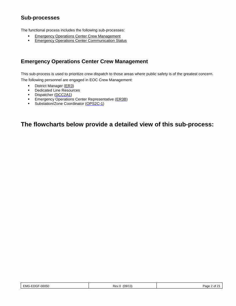
EMG-EDGF-00050 Rev.0 (09/13) Page 2 of 21
Sub-processes The functional process includes the following sub-processes:
Emergency Operations Center Crew Management Emergency Operations Center Communication Status
Emergency Operations Center Crew Management This sub-process is used to prioritize crew dispatch to those areas where public safety is of the greatest concern. The following personnel are engaged in EOC Crew Management:
District Manager (ER3) Dedicated Line Resources Dispatcher (DCC2A1) Emergency Operations Center Representative (ER3B) Substation/Zone Coordinator (OPS2C-1)
The flowcharts below provide a detailed view of this sub-process:
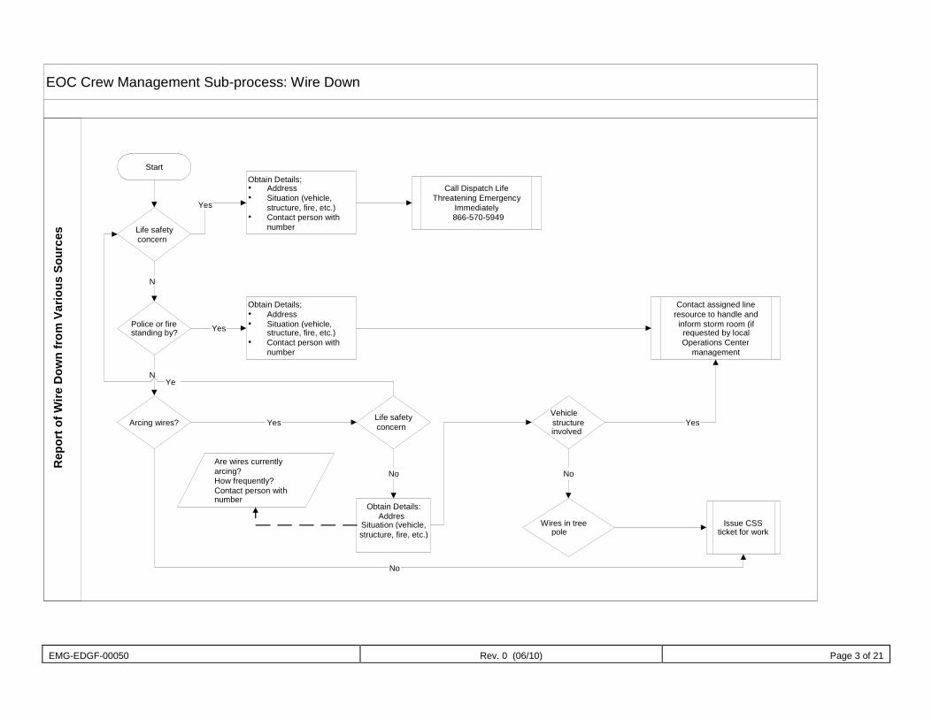
EMG-EDGF-00050 Rev. 0 (06/10) Page 3 of 21
EOC Crew Management Sub-process: Wire Down
Start
Life safety concern
Obtain Details; Address Situation (vehicle,
structure, fire, etc.) Contact person with
number
Call Dispatch Life Threatening Emergency
Immediately 866-570-5949
Police or fire standing by?
Arcing wires? Life safety concern
Obtain Details: Addres Situation (vehicle,
structure, fire, etc.)
Vehicle structure
involved
Wires in tree pole
Issue CSS
ticket for work
Yes
N
N
Yes
Obtain Details; Address Situation (vehicle,
structure, fire, etc.) Contact person with
number
Contact assigned line resource to handle and inform storm room (if requested by local Operations Center
management
Yes
Ye
No Are wires currently arcing? How frequently? Contact person with number
No
Yes
No
Rep
ort o
f Wire
Dow
n fr
om V
ario
us S
ourc
es
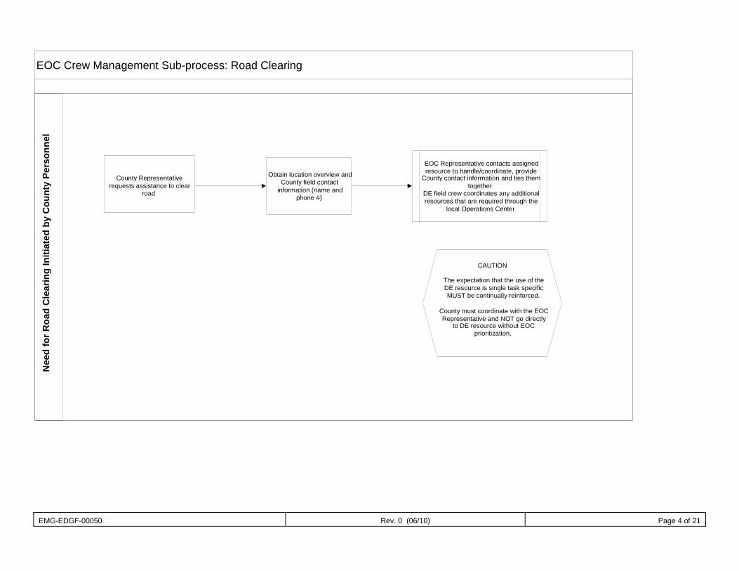
EMG-EDGF-00050 Rev. 0 (06/10) Page 4 of 21
EOC Crew Management Sub-process: Road Clearing
County Representative requests assistance to clear
road
Obtain location overview and County field contact
information (name and phone #)
EOC Representative contacts assigned resource to handle/coordinate, provide
County contact information and ties them together
DE field crew coordinates any additional resources that are required through the
local Operations Center
CAUTION The expectation that the use of the DE resource is single task specific MUST be continually reinforced.
County must coordinate with the EOC Representative and NOT go directly
to DE resource without EOC prioritization,
Nee
d fo
r Roa
d C
lear
ing
Initi
ated
by
Cou
nty
Pers
onne
l
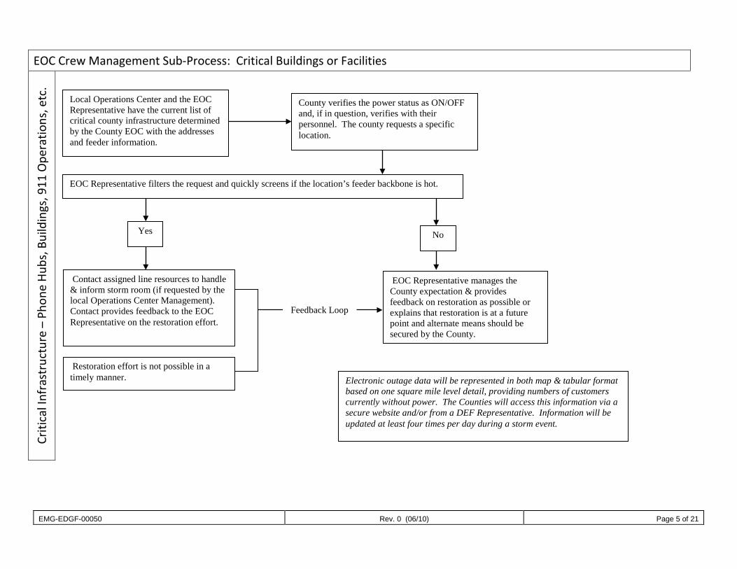
EMG-EDGF-00050 Rev. 0 (06/10) Page 5 of 21
EOC Crew Management Sub-Process: Critical Buildings or Facilities Cr
itica
l Inf
rast
ruct
ure
– Ph
one
Hubs
, Bui
ldin
gs, 9
11 O
pera
tions
, etc
.
Local Operations Center and the EOC Representative have the current list of critical county infrastructure determined by the County EOC with the addresses and feeder information.
County verifies the power status as ON/OFF and, if in question, verifies with their personnel. The county requests a specific location.
EOC Representative filters the request and quickly screens if the location’s feeder backbone is hot.
Yes No
Contact assigned line resources to handle & inform storm room (if requested by the local Operations Center Management). Contact provides feedback to the EOC Representative on the restoration effort.
EOC Representative manages the County expectation & provides feedback on restoration as possible or explains that restoration is at a future point and alternate means should be secured by the County.
Restoration effort is not possible in a timely manner.
Feedback Loop
Electronic outage data will be represented in both map & tabular format based on one square mile level detail, providing numbers of customers currently without power. The Counties will access this information via a secure website and/or from a DEF Representative. Information will be updated at least four times per day during a storm event.
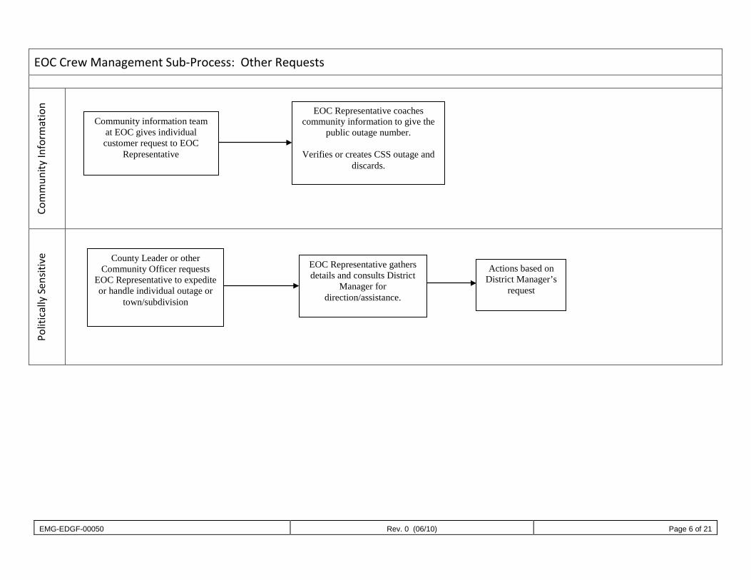
EMG-EDGF-00050 Rev. 0 (06/10) Page 6 of 21
EOC Crew Management Sub-Process: Other Requests
Com
mun
ity In
form
atio
n
Polit
ical
ly S
ensit
ive
EOC Representative coaches community information to give the
public outage number.
Verifies or creates CSS outage and discards.
Community information team at EOC gives individual customer request to EOC
Representative
Actions based on District Manager’s
request
EOC Representative gathers details and consults District
Manager for direction/assistance.
County Leader or other Community Officer requests
EOC Representative to expedite or handle individual outage or
town/subdivision
EMG-EDGF-00050 Rev. 0 (04/12) Page 7 of 25
Emergency Operations Center Communication (DEF Status) This sub-process provides a single point conduit of information and action between County Emergency Operation Centers (EOC) and Duke Energy. The goal is excellent customer service through organization, demonstration of commitment and a partnership collaboration to safely restore electrical service to county infrastructure and residents. The following personnel are engaged in EOC Communication:
District Manager (ER3) Dedicated Line Resources Emergency Operations Center Representative (ER3B) Substation/Zone Coordinator (OPS2C-1)
The flowchart below provides a detailed view of this sub-process:
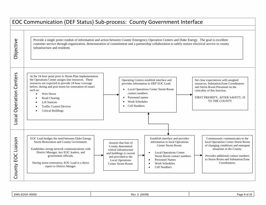
EMG-EDGF-00050 Rev. 0 (04/08) Page 8 of 25
EOC Communication (DEF Status) Sub-process: County Government Interface
Obj
ectiv
e
Loca
l Ope
ratio
n Ce
nter
s
Coun
ty E
OC
Liai
son
Provide a single point conduit of information and action between County Emergency Operation Centers and Duke Energy. The goal is excellent customer service through organization, demonstration of commitment and a partnership collaboration to safely restore electrical service to county infrastructure and residents
At the 24 hour point prior to Storm Plan implementation the Operations Center assigns line resources. These resources are expected to provide 24 hour coverage before, during and post storm for restoration of issues such as:
• Wire Down • Road Clearing • Lift Stations • Traffic Control Devices • Critical Buildings
Operating Centers establish interface and provides information to DEF EOC Lead.
• Local Operations Center Storm Room contact numbers
• Personnel names • Work Schedules • Cell Numbers
Set clear expectations with assigned resources, Substation/Zone Coordinators and Storm Room Personnel on the criticality of this function. FIRST PRIORITY, AFTER SAFETY, IS
TO THE COUNTY
EOC Lead bridges the need between Duke Energy Storm Restoration and County Government.
Establishes strong network communications with
District Manager, key EOC leaders, and government officials.
During storm restoration, EOC Lead is a direct
report to District Manger.
Assures that lists of County determined
critical infrastructure and buildings is current
and provided to the Local Operations
Center Storm Room.
Establish interface and provides information to local Operations
Center Storm Room.
• Local Operations Center Storm Room contact numbers
• Personnel Names • Work Schedules • Cell Numbers
Continuously communicates to the local Operations Center Storm Room of changing conditions and emergent
situations in the County.
Provides additional contact numbers to Storm Room and Substation/Zone
Coordinators.
EMG-EDGF-00050 Rev. 1 Page 9 of 21
Job Descriptions
ER1: Manager, Public Policy (External Relations Storm Coordinator)
Job Function The External Relations Storm Coordinator manages the development and implementation of storm preparation planning activities for Regulatory Affairs, LAM, and External Relations in Florida. The coordinator works with these groups to establish storm planning initiatives each year and to develop a process and resources needed to implement these initiatives. The coordinator is responsible for ensuring a full storm staffing compliment, developing system staffing scenarios, and training for all team members. The coordinator’s primary contacts are the District Manager (ER3), the Manager, Regulatory Affairs (ER2), and the Manager, LAM (ER4) for the storm preparation activities and during storm events. During storms, the coordinator facilitates the implementation of staffing, planning, team coordination meetings and resource support.
Job Description Assure process flow for all work types is understood and in place prior to the storm. Provide annual training for EOC Representatives (ER3B), District Manager Back-ups (ER3A), and Administrative
Support (ER1A). Provide general oversight for EOC Representatives (ER3B) and assure all performance expectations are met. Assure all pre-storm activities are completed for each EOC.
Key Interface Points System Storm Coordination Team Manager, LAM (ER4) District Manager (ER3) Manager, Regulatory Affairs (ER2) EOC Representatives (ER3B) Corporate Communications
Checklist of Actions
Before Major Storm Assure all pre-storm activities are completed. Collaborate with External Relations, Regulatory Affairs and LAM to assure all storm positions are properly
staffed. General communication to all team members on assignments and responsibilities Manage implementation of annual training for EOC Representatives (ER3B), District Manager Back-ups
(ER3A) and Administrative Support (ER1A). Review all process flow documents, job descriptions, staffing plans and other process information to
ensure they are updated as needed. Review and ensure team website is current and accessible to all team members. Participate in daily ER and Region storm calls and periodic Communications storm conference calls. Update on activities/potential issues in your area of responsibility.
During Major Storm Provide general oversight for team staffing and assure all performance expectations are met. Schedule and facilitate meetings before, during and after storm for coordination among team members
and management. Participate in daily ER and Region storm calls and periodic Communications storm conference calls. Update on activities/potential issues in your area of responsibility. Provide updates for system storm calls. Facilitate the provision of resources needed to support team actions including coordination with Corporate
Communications for support throughout storm events.
EMG-EDGF-00050 Rev. 1 Page 10 of 21
Assist as needed in local government support activities. After Major Storm
Coordinate lessons learned activities and implementation of results.
Tools and Information Needed Company laptop computer Company cellular phone (in some cases a company radio will also be required) Duke Energy shirts to be worn at the EOC Reliable vehicle appropriate to storm impacted areas
Training Requirements General leadership experience Company organizational knowledge Working knowledge of DEF distribution and transmission facilities and operational procedures Experience dealing with external public (e.g. elected officials) – strong communication skills Ability to work extended hours.
Engaged in the Following Sub-process: EOC Crew Management Sub-process: Wire Down EOC Crew Management Sub-process: Road Clearing EOC Crew Management Sub-process: Infrastructure (lift stations, well fields and traffic lights) EOC Crew Management Sub-process: Critical Buildings or Facilities EOC Crew Management Sub-process: Other Requests EOC Communication (DEF Status) Sub-process: County Government Interface
ER1A: Administrative Support/RSVP Coordinator
Job Function The Administrative Support (ER1A) will work in the region storm center or the local operations center depending on the severity of the storm and best allocation of available personnel. The Administrative Support (ER1A) will provide clerical support to the Manager of Public Policy (ER1), before, during and after a storm event. This position will also fulfill the role of RSVP Coordinator for the ER Storm Plan. This position may also be asked to initiate and maintain communications with government and key leaders.
Job Description Take a proactive approach to providing information to all public officials, Emergency Management personnel
and other identified key leaders in the area assigned by obtaining an updated list of public officials within your area of responsibility.
Communicate with the District Manager (ER3) and EOC Representatives (ER3B) for the exchange of timely and accurate information before, during and after a major storm.
Contact the local elected officials at the closing of the storm center to finalize the communication process. This position as the ER RSVP Coordinator is responsible for:
Keeping the RSVP tool updated as employees transfer in and out of the ER Storm Plan organization. Being the first point of contact for ER Storm Plan employees regarding RSVP questions or concerns. Assisting employees when signing up for their storm role. Participating in pre-storm season planning.
EMG-EDGF-00050 Rev. 1 Page 11 of 21
Key Interface Points Manager, Public Policy (ER1) District Manager (ER3) EOC Representative (ER3B) Back-up District Manager (ER3A)
Checklist of Actions for Administrative Support (ER1A)
Before Major Storm Assist in the facilitation of storm preparation activities including resource coordination, communications,
contact information updates, etc. Take a proactive approach to providing information to all public officials, emergency management
personnel and other identified key leaders in the area assigned as directed by leadership group, may include preparing communication packets.
May assist with initiating contact prior to the storm to keep communities and key leaders abreast of our preparations and maintain communication throughout the storm restoration period.
Organize meetings and assist with pre-storm training as needed.
During Major Storm Provide information to all public officials, emergency management personnel and other identified key
leaders in the area assigned as directed by District Manager (ER3). Provide administrative support including organizing meetings, travel, and resources as directed during
storm event.
After Major Storm Contact the local elected officials at the closing of the storm center to finalize the communication process. Fully support all Lessons Learned initiatives, post storm.
Checklist of Actions for ER RSVP Coordinator (ER1A) Before Storm Landfall
96-72 hours prior, begin identifying ER Storm Plan employees’ availability for storm duty and input data into RSVP tool.
72-48 hours prior, complete employee availability input into the RSVP tool and begin activation of employees. 48-24 hours prior, complete activation of all identified ER Storm Plan employees. 24-0 hours prior, finalize any pre-storm resource allocation plan adjustments in the RSVP tool.
During Restoration Effort
Periodically update resource allocation adjustments in the RSVP tool throughout the restoration effort. Release employees from ER Storm Plan support, as they become available, for use by other storm
organizations. Identify released ER Storm Plan employees that are not able to support other storm organizations as “Not
Available” in the RSVP tool. After Restoration Effort
Release all ER Storm Plan employees from the current storm in the RSVP tool. Participate in any lessons learned exercises after each storm event. Forward lessons learned results to the System RSVP Coordinator.
Supporting Tools
RSVP Tool RSVP Quick Reference Guidelines RSVP Training Manual
EMG-EDGF-00050 Rev. 1 Page 12 of 21
Tools and Information Needed
Access to computer with CSS and RSVP loaded. Company cellular phone (in some cases a company radio will also be required). Reliable vehicle appropriate to accessing storm impacted areas.
Training Requirements Participate in training sessions conducted by DEF. Working knowledge of customer service procedures and CSS and OMS. Experience dealing with external publics (e.g. elected officials) – strong communication skills. Ability to work extended hours.
Engaged in the Following Sub-process:
EOC Crew Management Sub-process: Wire Down EOC Crew Management Sub-process: Road Clearing EOC Crew Management Sub-process: Infrastructure (lift stations, well fields and traffic lights) EOC Crew Management Sub-process: Critical Buildings or Facilities EOC Crew Management Sub-process: Other Requests EOC Crew Management Sub-process: County Government Interface
Systems CSS, OMS
ER2: Manager, Regulatory Affairs (State Emergency Operations Center (SEOC) Coordinator) Job Function The SEOC Coordinator (ER2) interacts primarily with DEF personnel in the Distribution Storm Center (DCC), Transmission Storm Center, Energy Control Center and External Relations, as well as representatives from the Florida Public Service Commission (FPSC), Department of Environmental Protection (DEP), Department of Transportation (DOT), Law Enforcement, Military Support and the Governor’s Office. Job Description
• Oversight of EOC Representatives (State) (ER2A) assigned to State EOC. • Provide Regulatory updates for internal DEF Storm Calls before, during and after major storms. • Obtain the Governor’s Executive Order and distribute to DEF Logistics personnel for logistical purposes. • Prepare DOT Waivers and communicate with DOT SEOC personnel (ESF 16) to expedite arrival of out-of-
state crews prior to entry into the State of Florida. • Prepare Aviation Waivers and obtain approvals from ESF 1 & ESF 3 (DOT & Public Works). • Coordinate with DEF Storm Centers for the exchange of accurate information pertaining to restoration efforts
before, during and after a major storm. • Communicate with SEOC officials regarding power outage numbers by county and restoration efforts after a
major storm. • Communicate Key Messages with SEOC personnel. • Help DEF representatives with specific requests from a state level relating to restoration efforts. • Interact regularly with numerous positions in External Relations storm team. • Responsible for participation in DEF System Storm Calls, ER calls. • Responsible for DEF participation in the State Storm Drill.
EMG-EDGF-00050 Rev. 1 Page 13 of 21
Key Interface Points
• Governor’s Office • Florida Public Service Commission (FPSC) • Department of Environmental Protection (DEP) • Department of Transportation (DOT) • Law Enforcement • National Guard / Military Support • Distribution Storm Center (DCC) • Transmission Storm Center • Energy Control Center (ECC) • Numerous positions in External Relations storm team
Checklist of Actions Before Major Storm
• Responsible for DEF participation in the State Storm Drill. • Participate in daily ER and Region storm calls and periodic Communications storm conference calls.
Update on activities/potential issues in your area of responsibility. • Update storm manuals and emergency contact information. • Ensure Executive Orders are available to appropriate DEF personnel. • Communicate with the SEOC personnel the exchange of timely and accurate information of DEF efforts
being taken prior to a major storm making landfall (number of contract crews, shutdown of nuclear plant, etc.).
• Gather all DOT / Aviation data and report on appropriate forms. • Arrange for highway escorts for out-of-town crews/equipment and other travel arrangements (ex. Weigh
stations, tolls).
During Major Storm
• Participate in daily ER and Region storm calls and periodic Communications storm conference calls. Update on activities/potential issues in your area of responsibility.
• Communicate with the SEOC personnel the exchange of timely and accurate information. After Major Storm
• Communicate with the SEOC personnel the exchange of timely and accurate information. • Gather DEF storm manuals in Rm. ESF 12 of the SEOC and return to office. • Fully support all Lessons Learned initiatives, post storm.
Tools and Information Needed
• Company laptop computer with email and internet access • Duke Energy shirts to be worn at the SEOC
Training Requirements
• Experience dealing with elected officials – strong communication skills. • Knowledge of state computer tracking system. • Knowledge of DEF Storm Plans.
Engaged in the Following Sub-process: TBD
EMG-EDGF-00050 Rev. 1 Page 14 of 21
ER2A: EOC Representative (State)
Job Function The EOC Representative (State) (ER2A) interacts primarily with the Storm Center, District Manager (ER3), Back-up District Manager (ER3A), the Operating Center Liaison, and Corporate Communications during storm restoration activities. The EOC Representative (State) (ER2A) is located at the State Emergency Operations Center. The primary responsibility of the EOC Representative (State) (ER2A) is to work with the EOC personnel to establish current priorities for restoration, communicate this information to appropriate operating center personnel, and ensure EOC priorities are worked successfully. The EOC Representative (State) (ER2A) is also responsible for establishing contact with assigned EOC and updating storm restoration priority lists prior to the beginning of the storm season. Job Description
Establish contact with assigned EOC prior to June 1. Update storm restoration infrastructure priority lists throughout the year prior to June 1. Provide regular briefings and deliver key messages to EOC personnel. Coordinate with crews and/or storm center to ensure implementation of priority infrastructure restoration
process. Communicate with the District Manager (ER3) and Operation Center Liaison for the exchange of timely and
accurate information before, during and after a major storm.
Key Interface Points District Manager (ER3) Back-up District Manager (ER3B) Operating Center Liaison Corporate Communications EOC personnel
Checklist of Actions
Before Major Storm In coordination with Manager, LAM (ER4), work with county government to update EOC priorities (e.g.
designated hospitals, shelters, traffic lights, essential water treatment facilities and lift stations, etc.) and develop prioritized list for the operation centers.
Update list of all governmental facilities in the State including responsible operating center, substation, and feeder.
Review DEF procedures with EOC staff and establish working relationship and rules. Work with District Manager (ER3) and General Managers to review EOC priority work flow process. Electronic outage data will be represented in both map and tabular format. The State will have the ability to
view higher level outage data as well as each county separately, with detailed outage information based on one square kilometer grid level detail providing numbers and customers currently without power. The State will be provided this information at least four times each day during a storm event. The State will access the information on a secure web site and where necessary be provided the information manually by a DEF representative.
Assure a network connection that will accommodate a Duke Energy computer exists at the EOC. Attend scheduled meetings as the storm approaches.
During Major Storm Organize and report “911” type issues to Dispatch. Advise District Manager and Corporate Communications of the need for press briefings or public official
meetings. Participate in daily ER and Region storm calls and periodic Communications storm conference calls. Update
on activities/potential issues in your area of responsibility. Provide regular briefings and deliver key messages to EOC personnel. Communicate with the District Manager (ER3) and Operation Center Liaison for the exchange of timely and
accurate information before, during and after a major storm.
EMG-EDGF-00050 Rev. 1 Page 15 of 21
After Major Storm Responsible for “break-down” of DEF area in EOC facility. Fully support all Lessons Learned initiatives, post storm.
Tools and Information Needed
Company laptop computer with CSS loaded Company cellular phone (in some cases a company radio will also be required) Standard DEF storm kit Duke Energy shirts to be worn at the EOC Reliable vehicle appropriate for accessing storm impacted areas Able to work extended hours Must have the flexibility to relocate to hardest hit areas
Training Requirements Working knowledge of DEF distribution and transmission facilities and operational procedures Working knowledge of customer service procedures and CSS Experience dealing with external publics (e.g. elected officials) – strong communication skills Completion of NIMS training requirements
Engaged in the Following Sub-process: EOC Crew Management Sub-process: Wire Down EOC Crew Management Sub-process: Road Clearing EOC Crew Management Sub-process: Infrastructure (lift stations, well fields and traffic lights) EOC Crew Management Sub-process: Critical Buildings or Facilities EOC Crew Management Sub-process: Other Requests EOC Communication (DEF Status) Sub-process: County Government Interface
ER3: District Manager
Job Function This District Manager (ER3) position has overall responsibility for Duke Energy’s governmental coordination program in their assigned area working with public officials and other identified key leaders before, during and after hurricane restoration efforts. The District Manager will facilitate communication between DEF and the local governments providing timely updates. The District Manager will direct resources assigned to their team for the purpose of governmental coordination including EOC representatives, Back up District Managers and Administrative Support. The District Manager (ER3) will be headquartered in the region storm center.
Job Description Collaborate with local government and key leaders to:
o Facilitate the coordination of outage restoration by providing on-going updates before, during and after storm events.
o Educate the public on proper storm preparation and restoration actions. o Assist in the resolution of local governmental issues and concerns related to storm and emergency
situations.
Provide direction to a team of Back-up District Managers (ER3A), who are the main contact positions for communications with public officials, Emergency Management personnel and other identified key leaders in the area assigned - before, during and after the storm.
Interact with Operations Managers, Operation Center Liaisons, Corporate Communications, Region/System Storm Center, CSC, External Relations VP, etc. to gain knowledge of restoration priorities and efforts.
EMG-EDGF-00050 Rev. 1 Page 16 of 21
Participate in daily ER and Region storm calls and periodic Corporate Communications storm conference calls. Update on activities/potential issues in your area of responsibility.
Key Interface Points External Relations VP Manager, Public Policy (ER1) Back-up District Manager (ER3A) EOC Representative (ER3B) Administrative Support (ER1A) Operations Managers Operations Center Liaisons Corporate Communications Region/System Storm Center CSC Public Officials, Emergency Management personnel, other key leaders
Checklist of Actions
Before Major Storm Coordinate with Public Policy on storm initiatives, staffing plans, training and resource coordination.
Participate in planning meetings. Update list of all public officials and local contacts prior to June 1 in the External Relations shared storm
files. Conduct a minimum of 1 workshop per region statewide prior to storm season to include city/county staff
and emergency personnel. This will assist us in having protocols in place prior to storms as well as improving relationships and communications.
Participate in EOC and local government support training. Participate in daily ER and Region storm calls and periodic Corporate Communications storm conference
calls. Update on activities/potential issues in your area of responsibility. Oversee distribution of any pre-storm communications to the community leaders in your area of
responsibility.
During Major Storm Provide direction to a team of Back-up District Managers (ER3A) who are the main contact positions for
communications with public officials, Emergency Management personnel and other identified key leaders in the area assigned - before, during and after the storm.
Coordinate with Public Policy on storm staffing and resources coordination. Participate in daily ER and Region storm calls and periodic Communications storm conference calls.
Update on activities/potential issues in your area of responsibility. Interact with Operations Managers, Operation Center Liaisons, Public Policy, Corporate Communications,
Region/System Storm Center, CSC, External Relations VP, etc. for coordination and to gain knowledge of restoration priorities and efforts.
After Major Storm Ensure that the Back-up District Managers (ER3A) have finalized the communication process with local
elected officials, etc., by contact with local communities to ensure that there are no outstanding issues to resolve.
Fully support all Lessons Learned initiatives, post storm.
Tools and Information Needed Company laptop computer with CSS loaded Company cellular phone (in some cases a company radio will also be required) Standard DEF storm kit Duke Energy shirts to be worn when out visiting public. Reliable vehicle appropriate to accessing storm impacted areas.
EMG-EDGF-00050 Rev. 1 Page 17 of 21
Training Requirements Must have the flexibility to relocate to hardest hit areas Be able to drive to meetings of officials and Emergency Management, etc. General leadership experience Company organizational knowledge Working knowledge of DEF distribution and transmission facilities and operational procedures Experience dealing with external public (e.g. elected officials) – strong communication skills Able to work extended hours
Engaged in the Following Sub-process: EOC Crew Management Sub-process: Wire Down EOC Crew Management Sub-process: Road Clearing EOC Crew Management Sub-process: Infrastructure (lift stations, well fields and traffic lights) EOC Crew Management Sub-process: Critical Buildings or Facilities EOC Crew Management Sub-process: Other Requests EOC Crew Management Sub-process: County Government Interface
ER3A: Back-up District Manager
Job Function The Back-up District Manager (ER3A) will work in the region storm center, the local operations center, or as assigned, depending on the severity of the storm and best allocation of available personnel. The Back-up District Manager (ER3A) will be the main in-person contact for communication with public officials, emergency management personnel and other identified key leaders in the area assigned. This position is accountable to the District Manager (ER3) and will receive instruction and direction from that individual.
Job Description Take proactive approach to providing information to all public officials, Emergency Management
personnel and other identified key leaders in the area assigned, by obtaining an updated list of public officials within your area of responsibility.
Communicate with the District Manager (ER3) and EOC Representative (ER3B) for the exchange of timely and accurate information before, during and after a major storm.
Represent DEF at any community meetings before and during the storm. Contact the local elected officials at the closing of the storm center to finalize the communication process.
Key Interface Points District Manager (ER3) Manager, Public Policy (ER1) EOC Representative (ER3B) Administrative Support (ER1A) Public Officials, Emergency Management personnel, other identified key leaders
Checklist of Actions
Before Major Storm Taking proactive approach to providing information to all public officials, emergency management
personnel and other identified key leaders in the area assigned as directed by District Manager (ER3). Communicate with the District Manager (ER3) and EOC Representative (ER3B) for the exchange of
timely and accurate information before, during and after a major storm.
EMG-EDGF-00050 Rev. 1 Page 18 of 21
Coordinate, when necessary with local Emergency Preparedness Personnel concerning evacuations and emergency shelters.
Represent PE at any community meetings before and during the storm. During Major Storm
Provide information to all public officials, emergency management personnel and other identified key leaders in the area assigned as directed by District Manager (ER3).
Communicate with the District Manager (ER3) and, when necessary, the EOC Representative (ER3B), for the exchange of timely and accurate information before, during and after a major storm.
Coordinate, when necessary, with local Emergency Preparedness Personnel concerning evacuations and emergency shelters.
Represent DEF at community meetings before and during the storm. Participate in daily ER and Region storm calls and periodic Communications storm conference calls.
Update on activities/potential issues in your area of responsibility.
After Major Storm Contact the local elected officials at the closing of the storm center to finalize the communication process. Fully support all Lessons Learned initiatives, post storm.
Tools and Information Needed Access to computer with CSS loaded Company cellular phone (in some cases a company radio will also be required) Duke Energy shirts to be worn when out visiting the public Reliable vehicle appropriate to accessing storm impacted areas
Training Requirements Participate in EOC and local governmental training sessions conducted by DEF Working knowledge of DEF distribution and transmission facilities and operational procedures Working knowledge of customer service procedures and CSS Experience dealing with external public (e.g. elected officials) – strong communication skills Able to work extended hours Must have the flexibility to relocate to hardest hit areas
Engaged in the Following Sub-process: EOC Crew Management Sub-process: Wire Down EOC Crew Management Sub-process: Road Clearing EOC Crew Management Sub-process: Infrastructure (lift stations, well fields and traffic lights) EOC Crew Management Sub-process: Critical Buildings or Facilities EOC Crew Management Sub-process: Other Requests EOC Crew Management Sub-process: County Government Interface
EMG-EDGF-00050 Rev. 1 Page 19 of 21
ER3B: EOC Representative (County)
Job Function The EOC Representative (ER3B) interacts primarily with the Storm Center, District Manager Managers (ER3), Back-up District Manager (ER3A), Operating Center Liaisons, and Corporate Communications during storm restoration activities. The EOC Representative (ER3B) is located at the Emergency Operations Center. The primary responsibility of the EOC Representative (ER3B) is to work with the EOC personnel to establish current priorities for restoration, communicate this information to appropriate operating center personnel, and ensure EOC priorities are worked successfully. The EOC Representative (ER3B) is also responsible for establishing contact with the assigned EOC and updating storm restoration priority lists prior to the beginning of the storm season. Job Description Establish contact with assigned EOC prior to June 1. EOC representative participates in local operations center phone calls prior and during storm events as appropriate.
Update storm restoration infrastructure priority lists throughout the year prior to June 1. Provide regular briefings on PE Duke and deliver key messages to EOC personnel. Coordinate with crews and or storm center to ensure implementation of priority infrastructure restoration
process. Communicate with the District Manager (ER3) and the Operation Center Liaisons for the exchange of timely
and accurate information before, during and after a major storm.
Key Interface Points District Manager (ER3) Back-up District Manager (ER3B) Operating Center Liaisons Corporate Communications EOC personnel
Checklist of Actions
Before Major Storm In coordination with the Manager, LAM (ER4), the EOC Representative (ER3B) works with local governments
to update specific city/county and EOC priorities (e.g. designated hospitals, shelters, traffic lights, essential water treatment facilities and lift stations, etc.) and develops a prioritized list for each county.
Create a list of all governmental facilities in the County, including responsible operating center, substation, and feeder.
Review PE procedures with EOC staff and establish working relationship and rules. Work with District Manager (ER3), DOMs, and Operation Center Liaisons to establish EOC priority work flow
process. Electronic outage data will be represented in both map and tabular format to meet the varying technology
capabilities of the EOCs. EOCs will receive detailed outage information based on one square kilometer grid detail providing numbers and customers currently without power. The EOCs will be provided this information at least four times each day during a storm event. The EOCs will access the information on a secure web site and, where necessary, be provided the information manually by a DEF representative.
Assure a network connection that will accommodate a Duke Energy computer exists at the EOC. Attend scheduled meetings as the storm approaches.
During Major Storm Organize and report “911” type issues to Dispatch. Advise District Manager and Corporate Communications of the need for press briefings or public official
meetings. Participate in daily ER and Region storm calls and periodic Corporate Communications storm conference
calls. Update on activities/potential issues in your area of responsibility. Provide regular briefings and deliver key messages to EOC personnel.
EMG-EDGF-00050 Rev. 1 Page 20 of 21
Communicate with the District Manager (ER3) and Operation Center Liaisons for the exchange of timely and accurate information before, during and after a major storm.
After Major Storm Responsible for “break-down” of DEF area in EOC facility. Fully support all Lessons Learned initiatives, post storm.
Tools and Information Needed Company laptop computer with CSS loaded Company cellular phone (in some cases a company radio will also be required) Standard DEF storm kit Duke Energy shirts to be worn at the EOC Reliable vehicle appropriate for accessing storm impacted areas Able to work extended hours Must have the flexibility to relocate to hardest hit areas
Training Requirements
Working knowledge of DEF distribution and transmission facilities and operational procedures Working knowledge of customer service procedures and CSS Experience dealing with external publics (e.g. elected officials) – strong communication skills Completion of NIMS training requirements
Engaged in the Following Sub-process: EOC Crew Management Sub-process: Wire Down EOC Crew Management Sub-process: Road Clearing EOC Crew Management Sub-process: Infrastructure (lift stations, well fields and traffic lights) EOC Crew Management Sub-process: Critical Buildings or Facilities EOC Crew Management Sub-process: Other Requests EOC Communication (DEF Status) Sub-process: County Government Interface
ER4: Manager, LAM
Job Function The Manager, LAM, is the primary contact for the Manager, Public Policy (ER1) for storm preparation activities including, assignment of LAM representatives to EOCs and infrastructure priority lists. The Manager, LAM (ER4) has the responsibility for relationships with LAM customers during storm restoration activities.
Job Description Assure process flow for all work types is understood and in place prior to the storm. Provide annual training for EOC Representatives (ER3B) and LAM Support Line representatives. Provide general oversight for EOC Representatives (ER3B) and assure all performance expectations are met. Collaborate with Public Policy and District Manager to assure EOCs are properly staffed. Assure all pre storm activities are completed for each EOC.
Key Interface Points Manager, Public Policy (ER1) District Manager (ER3) EOC Representatives (ER3B)
EMG-EDGF-00050 Rev. 1 Page 21 of 21
Checklist of Actions
Before Major Storm Assure process flow for all work types is understood and in place prior to the storm. Provide annual training for EOC Representatives (ER3B) and LAM Support Line representatives. Provide general oversight for EOC Representatives (ER3B) and assure all performance expectations are
met. Collaborate with District Manager and Public Policy to assure EOCs are properly staffed. Assure all pre storm activities are completed for each EOC. These include:
Work with local governments to update specific city/county and EOC priorities (e.g. designated hospitals, shelters, traffic lights, essential water treatment facilities and lift stations, etc.) and develop a prioritized infrastructure list for each county. Create a list of all governmental facilities in the County including responsible operating center, substation, and feeder. Review and update EOC priority work flow process Assure a network connection that will accommodate a Duke Energy computer exists at the EOC.
During Major Storm Ensure that the LAM representative’s assignments to EOCs are met. Provide updated infrastructure priority list. Responsible for relationships with LAM customers during storm restoration activities Responsible for supporting the coordination of a dedicated LAM contact line.
During a major storm, the Storm Outage Restoration Line (SORL) will be activated. Proactive outreach will begin immediately, with employees communicating estimated damage and established estimated restoration timelines (ERTs) via emails and phone calls.
Participate in daily ER and Region storm calls and periodic Communications storm conference calls. Update on activities/potential issues in your area of responsibility.
After Major Storm Support Lessons Learned (both internal and with the EOCs) initiatives, representing the EOC
Coordination efforts.
Tools and Information Needed Company laptop computer with CSS loaded Company cellular phone (in some cases a company radio will also be required) Standard DEF storm kit Duke Energy shirts to be worn at the EOC Reliable vehicle appropriate to storm impacted areas
Training Requirements
General leadership experience Company organizational knowledge Working knowledge of DEF distribution and transmission facilities and operational procedures Experience dealing with external public (e.g. elected officials) – strong communication skills Able to work extended hours
Engaged in the Following Sub-process: EOC Crew Management Sub-process: Infrastructure (lift stations, well fields and traffic lights) EOC Crew Management Sub-process: Critical Buildings or Facilities
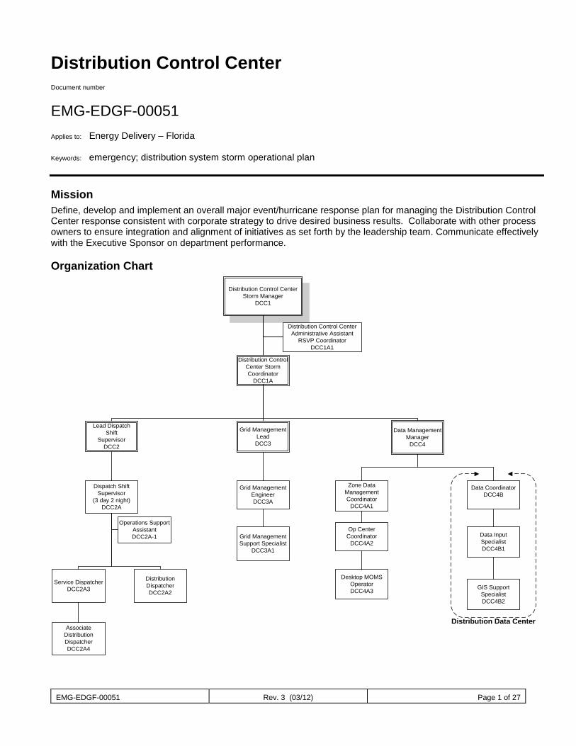
EMG-EDGF-00051 Rev. 3 (03/12) Page 1 of 27
Distribution Control Center Document number
EMG-EDGF-00051 Applies to: Energy Delivery – Florida Keywords: emergency; distribution system storm operational plan
Mission Define, develop and implement an overall major event/hurricane response plan for managing the Distribution Control Center response consistent with corporate strategy to drive desired business results. Collaborate with other process owners to ensure integration and alignment of initiatives as set forth by the leadership team. Communicate effectively with the Executive Sponsor on department performance.
Organization Chart
Distribution Control Center Storm Manager
DCC1
Distribution Control Center Storm Coordinator
DCC1A
Distribution Control Center Administrative Assistant
RSVP Coordinator DCC1A1
Grid Management LeadDCC3
Data Management Manager
DCC4
Lead Dispatch Shift
SupervisorDCC2
Dispatch Shift Supervisor
(3 day 2 night)DCC2A
Operations Support AssistantDCC2A-1
Service DispatcherDCC2A3
Distribution Dispatcher DCC2A2
Associate Distribution Dispatcher DCC2A4
Grid Management Engineer DCC3A
Grid Management Support Specialist
DCC3A1
Data Coordinator DCC4B
Zone Data Management Coordinator
DCC4A1
Op Center Coordinator
DCC4A2Data Input SpecialistDCC4B1
Distribution Data Center
GIS Support SpecialistDCC4B2
Desktop MOMSOperatorDCC4A3
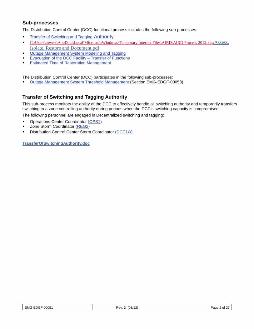
EMG-EDGF-00051 Rev. 3 (03/12) Page 2 of 27
Sub-processes The Distribution Control Center (DCC) functional process includes the following sub-processes:
Transfer of Switching and Tagging Authority C:\Users\mwest\AppData\Local\Microsoft\Windows\Temporary Internet Files\AIRD\AIRD Process 2012.xlsxAssess,
Isolate, Restore and Document.pdf Outage Management System Modeling and Tagging Evacuation of the DCC Facility – Transfer of Functions Estimated Time of Restoration Management The Distribution Control Center (DCC) participates in the following sub-processes: Outage Management System Threshold Management (Section EMG-EDGF-00053)
Transfer of Switching and Tagging Authority This sub-process monitors the ability of the DCC to effectively handle all switching authority and temporarily transfers switching to a zone controlling authority during periods when the DCC’s switching capacity is compromised. The following personnel are engaged in Decentralized switching and tagging: Operations Center Coordinator (OPS1) Zone Storm Coordinator (REG2) Distribution Control Center Storm Coordinator (DCC1A) TransferOfSwitchingAuthority.doc
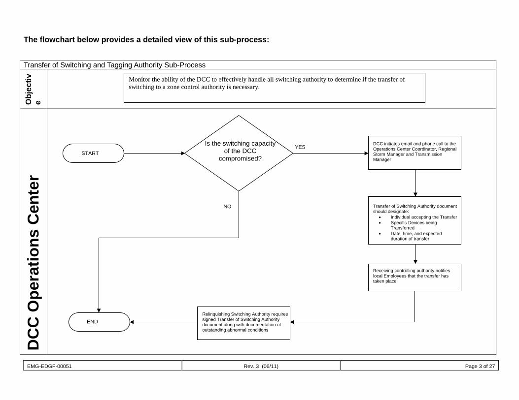
EMG-EDGF-00051 Rev. 3 (06/11) Page 3 of 27
The flowchart below provides a detailed view of this sub-process:
Transfer of Switching and Tagging Authority Sub-Process
Obj
ectiv
e
DC
C O
pera
tions
Cen
ter
Monitor the ability of the DCC to effectively handle all switching authority to determine if the transfer of switching to a zone control authority is necessary.
Is the switching capacity of the DCC
compromised?
DCC initiates email and phone call to the Operations Center Coordinator, Regional Storm Manager and Transmission Manager
Transfer of Switching Authority document should designate:
• Individual accepting the Transfer • Specific Devices being
Transferred • Date, time, and expected
duration of transfer
Receiving controlling authority notifies local Employees that the transfer has taken place
Relinquishing Switching Authority requires signed Transfer of Switching Authority document along with documentation of outstanding abnormal conditions
END
START YES
NO
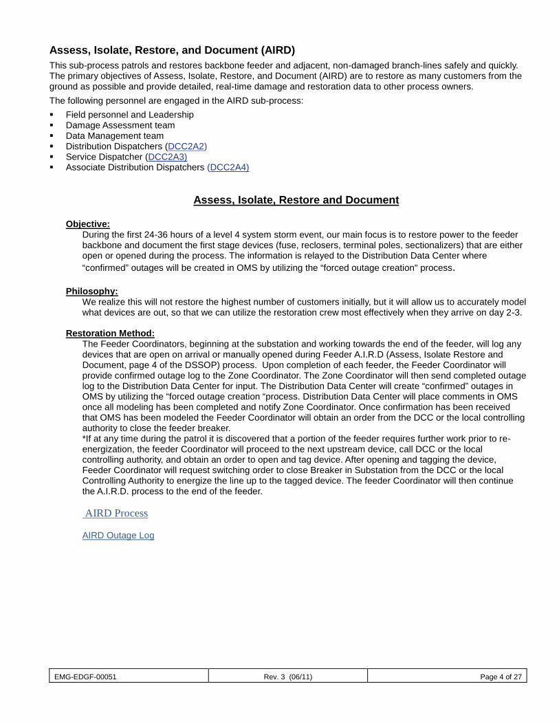
EMG-EDGF-00051 Rev. 3 (06/11) Page 4 of 27
Assess, Isolate, Restore, and Document (AIRD) This sub-process patrols and restores backbone feeder and adjacent, non-damaged branch-lines safely and quickly. The primary objectives of Assess, Isolate, Restore, and Document (AIRD) are to restore as many customers from the ground as possible and provide detailed, real-time damage and restoration data to other process owners. The following personnel are engaged in the AIRD sub-process: Field personnel and Leadership Damage Assessment team Data Management team Distribution Dispatchers (DCC2A2) Service Dispatcher (DCC2A3) Associate Distribution Dispatchers (DCC2A4)
Assess, Isolate, Restore and Document Objective: During the first 24-36 hours of a level 4 system storm event, our main focus is to restore power to the feeder
backbone and document the first stage devices (fuse, reclosers, terminal poles, sectionalizers) that are either open or opened during the process. The information is relayed to the Distribution Data Center where “confirmed” outages will be created in OMS by utilizing the “forced outage creation" process.
Philosophy: We realize this will not restore the highest number of customers initially, but it will allow us to accurately model
what devices are out, so that we can utilize the restoration crew most effectively when they arrive on day 2-3. Restoration Method:
The Feeder Coordinators, beginning at the substation and working towards the end of the feeder, will log any devices that are open on arrival or manually opened during Feeder A.I.R.D (Assess, Isolate Restore and Document, page 4 of the DSSOP) process. Upon completion of each feeder, the Feeder Coordinator will provide confirmed outage log to the Zone Coordinator. The Zone Coordinator will then send completed outage log to the Distribution Data Center for input. The Distribution Data Center will create “confirmed” outages in OMS by utilizing the “forced outage creation “process. Distribution Data Center will place comments in OMS once all modeling has been completed and notify Zone Coordinator. Once confirmation has been received that OMS has been modeled the Feeder Coordinator will obtain an order from the DCC or the local controlling authority to close the feeder breaker.
*If at any time during the patrol it is discovered that a portion of the feeder requires further work prior to re-energization, the feeder Coordinator will proceed to the next upstream device, call DCC or the local controlling authority, and obtain an order to open and tag device. After opening and tagging the device, Feeder Coordinator will request switching order to close Breaker in Substation from the DCC or the local Controlling Authority to energize the line up to the tagged device. The feeder Coordinator will then continue the A.I.R.D. process to the end of the feeder.
AIRD Process AIRD Outage Log
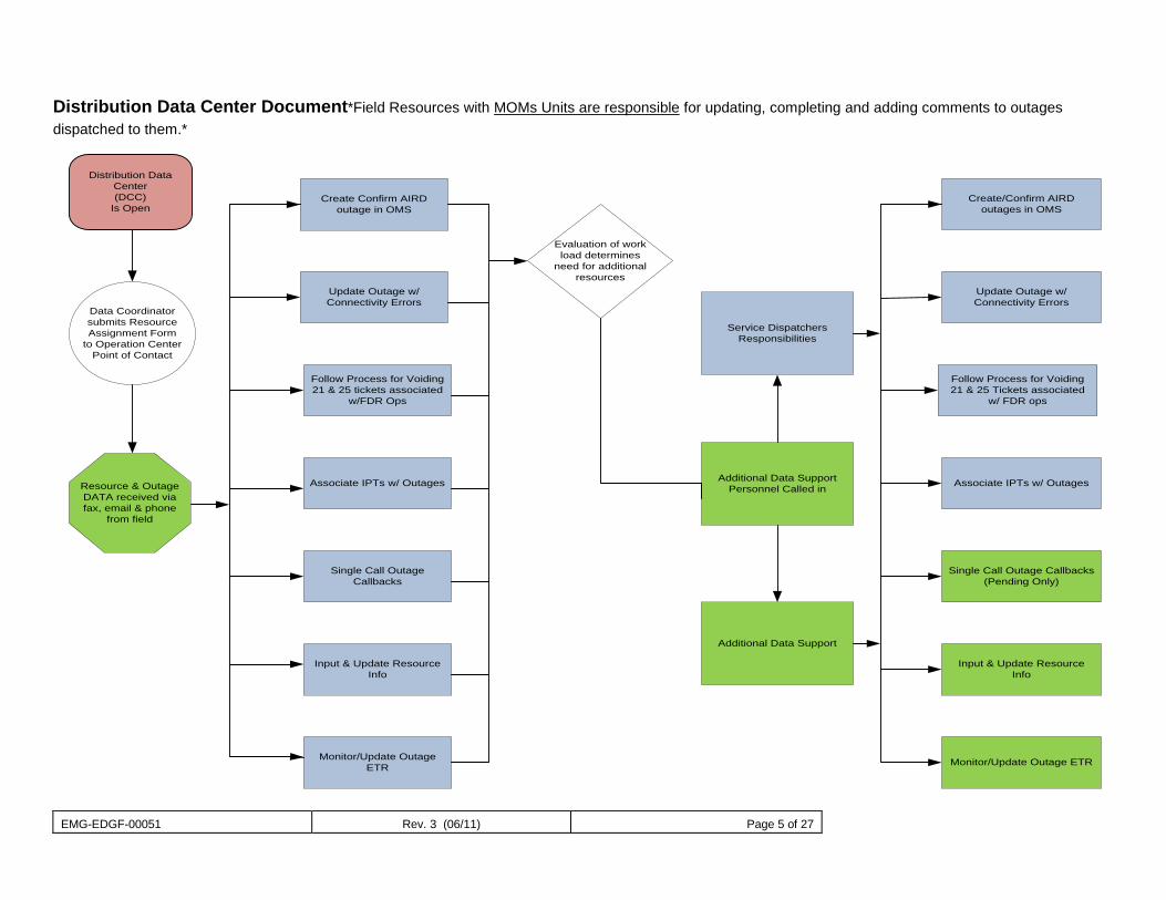
EMG-EDGF-00051 Rev. 3 (06/11) Page 5 of 27
Distribution Data Center Document*Field Resources with MOMs Units are responsible for updating, completing and adding comments to outages dispatched to them.*
Distribution Data Center (DCC)
Is Open Create Confirm AIRD
outage in OMS
Update Outage w/Connectivity Errors
Create/Confirm AIRD outages in OMS
Follow Process for Voiding 21 & 25 tickets associated
w/FDR Ops
Associate IPTs w/ Outages
Single Call Outage Callbacks
Input & Update Resource Info
Monitor/Update Outage ETR
Evaluation of work load determines
need for additional resources
Service Dispatchers Responsibilities
Additional Data Support Personnel Called in
Additional Data Support
Update Outage w/Connectivity Errors
Follow Process for Voiding 21 & 25 Tickets associated
w/ FDR ops
Associate IPTs w/ Outages
Single Call Outage Callbacks(Pending Only)
Input & Update Resource Info
Monitor/Update Outage ETR
Data Coordinator submits Resource Assignment Form
to Operation Center Point of Contact
Resource & Outage DATA received via fax, email & phone
from field
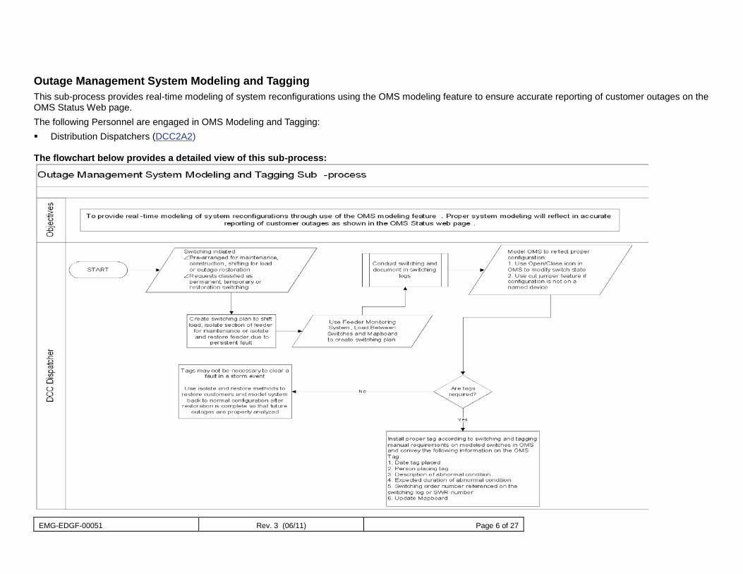
EMG-EDGF-00051 Rev. 3 (06/11) Page 6 of 27
Outage Management System Modeling and Tagging This sub-process provides real-time modeling of system reconfigurations using the OMS modeling feature to ensure accurate reporting of customer outages on the OMS Status Web page. The following Personnel are engaged in OMS Modeling and Tagging: Distribution Dispatchers (DCC2A2) The flowchart below provides a detailed view of this sub-process:
EMG-EDGF-00051 Rev. 3 (06/11) Page 7 of 27
Evacuation of the DCC Facility – Transfer of Functions This sub-process describes the steps necessary if a storm of significant magnitude forces the total evacuation of the DCC facility. Analysis of System
Radio- wide area radio communications would be lost with Prime site damage. Radio sites would go into site trunking if not storm damaged. The communication would only operate in a ‘line of sight’ mode between the communication tower and a “field” radio.
OMS primary servers- Back-up servers at Northpoint would need to be activated. DSCADA system damage- at this time there is no recovery for the loss of EMS equipment at the ECC facility. Web FG will be used for read only DSCADA when decentralizing Dispatchers yet DSCADA is still operational
at the ECC facility. Phone system damage. - With the loss of the ECC site phone switches (Baker and Harris) internal phone
numbers would become in operable. The Operation Center “800”numbers would need to be re-routed. The Life Threatening number “911” would need to be re-routed to Clearwater RSO (Buena Vista RSO alternate back-up).
Mapboard - Back-up plan would be activated using standalone workstation application. The most recent copies of the Mapboard would be utilized. While this option does not allow for the sharing of “red lines” each Distribution Dispatcher could share this information with adjoining dispatchers to ensure feeder configuration is widely known. For this reason, it is imperative that the OMS application be maintained during normal every day Operations.
The recovery solution varies from rudimentary recovery of OMS and basic radio communications to complex providing approx. 90% recovery of dispatch system functionality. Factors impacting any solution would include the amount of physical damage and the availability of employees.
Relocation of DCC Personnel Scenario 1 – Report to the Operating Centers/RSO/Northpoint North Coastal Zone- Reporting to Ocala RSO (4 Distribution Dispatchers, 2 Service Dispatchers, 1 DCC Supervisor)
Assignments Inverness- 1 day Distribution Dispatcher Ocala- 1 day Distribution Dispatcher Monticello- 1-day Distribution Dispatcher North Coastal Zone- 1 night Distribution Dispatcher, 2 night Service Dispatchers, 1 DCC Supervisor (Phone coverage only)
North Central Zone Reporting to Northpoint (5 Distribution Dispatchers, 2 Service Dispatchers, 1 DCC Supervisor 1 Grid Management Manager, 1 DCC RSVP Coordinator, 1 Technical Support Specialist, 1 GIS Technical Support Specialist, 1 Administrative Assistant, 1 OSA) Assignments
Apopka- 1 day Distribution Dispatcher Deland- 1 day Distribution Dispatcher Jamestown-1 day Distribution Dispatcher
Longwood- 1 day Distribution Dispatcher North Central Zone-2 night Distribution Dispatchers, 2 Service Dispatchers, 1 DCC Supervisor
EMG-EDGF-00051 Rev. 3 (06/11) Page 8 of 27
South Central Zone- Reporting to Buena Vista RSO (6 Distribution Dispatchers, 2 Service Dispatchers, 1 DCC Supervisor) Assignments
Winter Garden- 1 day Distribution Dispatcher Buena Vista- 1 day Distribution Dispatcher South East Orlando- 1 day Distribution Dispatcher Lake Wales / Highlands -1 day Distribution Dispatcher South Central Zone - 2 night Distribution Dispatchers, 2 Service Dispatchers, 1 DCC Supervisor
South Coastal Zone- Reporting to Clearwater RSO (6 Distribution Dispatchers, 2 Service Dispatchers, 1 DCC Supervisor) Assignments
St. Petersburg- 1 day Distribution Dispatcher Walsingham- 1 day Distribution Dispatcher
Clearwater- 1 day Distribution Dispatcher Seven Springs / Zephyrhills- 1 day Distribution Dispatcher
South Coastal Zone – 2 night Distribution Dispatchers, 2 Service Dispatchers, 1 DCC Supervisor (phone)
Core DCC Data Management Team- 1 Data Management Manager, 6 Outage Auditors, and 1 Data
Coordinator Team to be deployed to Winter Garden training center
Transmission- Northpoint-1 Grid Management Engineer
Core Team- 4 Distribution Dispatchers, 1 DCC Supervisor Corporate Storm Center- Winter Garden Director DCC
Relocation Timeline
48 to 36 hrs Have Personnel prepare for self for storm
o Home o Family
Identify Dispatchers available and designate a staging location o Call Personnel at home to communicate work assignment
Notify IT&T , Fleet and Zones of relocation plan activation Pick up ‘fleet’ vehicles
Stop all non-emergent switching functions Return all facilities to normal configuration as possible
Feeders Substations
DCC Personnel prepare for offsite relocation Begin minimum staffing
36 to 24 hrs. Activation of the OMS DR(Disaster Recovery) servers in Northpoint Verify OMS is modeled Begin equipment and Personnel relocation Supervisors and Engineers move to offsite locations Core/Return Team to remain in DCC Run CD’s with current Mapboard configuration
EMG-EDGF-00051 Rev. 3 (06/11) Page 9 of 27
24 to 12 hrs. Issue de-centralized switching authority document Begin offsite Dispatching Night Shift Operations will be located at RSO locations until Prime site failure Prepare for South Coastal staging
0 hrs. to 12 hrs. Final shut down of DCC Move to safe staging for storm passing
0 to plus 12hrs. – After Storm DCC Supervisor in South Coastal to contact Grid Management Lead for update on ECC facility assessment. Return team for assessment of DCC
o Site security o Identify damage
Identify locations for local dispatching o Set-up o work
Estimated Time of Restoration Management This sub-process gathers the information required to develop and maintain an accurate distribution system ETR. The following Personnel are engaged in ETR Management:
Damage Assessor (DA2A1) Desktop MOMS Operator (DCC4A3) Distribution Dispatcher (DCC2A2) Operations Center Damage Assessment Coordinator (DA2A) Op Center Coordinator (DCC4A2) Zone Data Management Coordinator (DCC4A1) Zone Damage Assessment Coordinator (DA2) System Damage Assessment Coordinator (DA1) (DCC4A) Tactical Management Coordinator (OPS2)
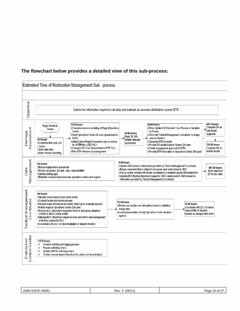
EMG-EDGF-00051 Rev. 3 (06/11) Page 10 of 27
The flowchart below provides a detailed view of this sub-process:
EMG-EDGF-00051 Rev. 3 (06/11) Page 11 of 27
Job Descriptions DCC1 Distribution Control Center Storm Manager
Job Function This position will typically be filled by the Director of the Distribution Control Center. This position is the lead for the Distribution Control Center storm Organization.
Job Description This position manages the overall Distribution Control Center storm plan and engages the Distribution Control Center storm organization to meet the daily system goals. This position maintains a strategic approach to the storm restoration effort.
Key Interface Points Executive Sponsor (CMS1) Zone Storm Manager (REG2) Distribution System Storm Coordinator (DSSC1) Distribution Storm Coordinator (DCC1A) Corporate Communications Manager (CC1)
Checklist of Actions C:\Users\mwest\AppData\Local\Microsoft\Windows\Temporary Internet Files\Content.Outlook\E1L5M3WN\DCC Storm Prep Checklist changes (2).docx DCC Storm Prep Checklist.docx
Tools and Information Needed • Distribution Control Center major storm plan. • Distribution Control Center staffing plans. • Contact list for entire Operations Center storm organization chart • County EOC issues spreadsheet • Priority customer/feeder list
DCC1A: Distribution Control Center Storm Coordinator Job Function Define, develop and implement an overall major event/hurricane response plan for managing the Distribution Control Center response consistent with corporate strategy. Job Description Provide relevant Performance metric information via the System storm calls to other Process Owners. Collaborate with Process Owners to develop an Estimated Time of Restoration, ensure DCC storm organizations (Dispatch, Grid Management, & Data Management) are staffed effectively to ensure the organization’s success, and assure switching orders and Operations are not delaying effective restoration. Be prepared to de-centralize switching authority should the need to do so arise. Provide governance oversight to the Storm Manager, Communication Manager and other department functions as necessary to achieve corporate objectives. Develop and implement effective change management plans related to storm response in order to educate and arm champions of the process. Identify Performance improvement opportunities and lead post storm lessons learned meetings with DCC organization to share and participate during system level lessons learned calls. Develop a plan to drive the resolution of identified lessons learned. This position is directly accountable to the Distribution Control Center Storm Manager and the Executive Sponsor in achievement of Performance metrics.
EMG-EDGF-00051 Rev. 3 (06/11) Page 12 of 27
Key Interface Points
Executive Sponsor (CMS1) Distribution System Storm Coordinator (DSSC1) Distribution Control Center Storm Manager (DCC1) Corporate Communications Director (CC1) Grid Management Lead (DCC3) Lead Dispatch Shift Supervisor (DCC2) Data Management Manager (DCC4) Checklist of Actions DCC Storm Prep Checklist.docx Tools and Information Needed
Estimated time of service restoration from Energy Distribution. Complete Distribution Control Center/ Storm Plan Complete Staffing plans and Communication Strategy
Training Requirements
Review and understand past major event performance, tools and capabilities. DCC1B Distribution Control Center Administrative Assistant RSVP Coordinator
Job Function This position will fulfill the role of RSVP Coordinator and provide administrative support to the Distribution Control Center.
Job Description
Act as the first point of contact for the Distribution Control Center employees regarding RSVP and maintain the RSVP to ensure the document contains the most accurate information. Provide administrative assistance to the Distribution Control Center. Maintain storm items such as charge codes, storm cards and supplies. Collaborate with supporting areas (Zone Storm Centers, Dispatch, Grid Management & Data Management) to ensure the Distribution Control Center has the most accurate information at all times, including emergency contact information. Coordinate with the ECC and Distribution Control Center Operations Support Assistant to ensure the facilities are maintained in a clean and safe manner at all times. Act as liaison between the Distribution Control Center employees, Staging and Logistics and fleet department to ensure all travel and lodging needs of the Distribution Control Center are met and communicated. Ensure all Distribution Control Center employees and supporting Personnel NERC CIP status are current and up-to-date. Coordinate any training that needs to be completed. This position is directly accountable to the Distribution Control Center Storm Manager and the Distribution Control Center Storm Coordinator.
Key Interface Points
Distribution Control Center Storm Manager (DCC1) Distribution Control Center Storm Coordinator (DCC1A) Lead Dispatch Shift Supervisor (DCC2) Grid Management Lead (DCC3) Data Management Manager (DCC4) Operations Support Assistant (DCC2A1) Zone Storm Coordinator (REG2)
EMG-EDGF-00051 Rev. 3 (06/11) Page 13 of 27
Checklist of Actions DCC Storm Prep Checklist.docx Tools and Information Needed
• Distribution Control Center major storm plan • Distribution Control Center staffing plans • RSVP Tool • Staging and Logistics process • Contact list for key interface positions • Employee NERC CIP status
DCC2: Lead Dispatch Shift Supervisor Job Function This position reports directly to the Distribution Control Center Storm Coordinator. This position coordinates the Distribution Control Center execution of the Hurricane/Major Event storm plan. Job Description This position is responsible for communicating the Distribution Control Center Performance metrics. This position will conduct and lead the Distribution Control Center major event coordination meetings. In addition, this position will coordinate with the other Shift Supervisors to ensure effective, consistent communication to internal customers, employees and other process owners. This position will collaborate with Distribution Storm Coordinator on adjustments necessary to the Distribution Control Center to ensure successful execution of the storm plan. Be prepared to de-centralize switching authority should the need arise. Assess the need for the relocation of the DCC Operations; if relocation is necessary provide oversight of staffing and locations in which individuals will be assigned. Provide governance oversight to the Distribution Control Center Shift Supervisors and other Distribution Control Center employees to achieve corporate objectives. Develop and implement effective change management plans related to storm response in order to educate and arm champions of the process. Identify performance improvement opportunities and lead post storm lessons learned meetings with Distribution Control Center organization to share and participate during system level lessons learned calls. Develop a plan to drive the resolution of identified lessons learned. This position is directly accountable to the Distribution Control Center Storm Manager.
Key Interface Points
Distribution Storm Coordinator (DCC1A) Dispatch Shift Supervisors (DCC2A) Grid Management Lead (DCC3) Grid Management Support Specialist (DCC3A1) Distribution Control Center Administrative Assistant RSVP Coordinator (DCC1B) Data Management Manager (DCC4) Data Input Specialist (DCC4B1) GIS Support Specialist (DCC4B2)
Checklist of Actions DCC Storm Prep Checklist.docx
EMG-EDGF-00051 Rev. 3 (06/11) Page 14 of 27
Tools and Information Needed
Distribution Control Center major storm plan. Distribution Control Center staffing plans. State of the Grid Intranet Internet Mapboard Microsoft Applications Load Between Switches FMS Switching Orders Application (DEF) DSCADA VMS OMS AIRD Process D1’s Process
DCC2A: Dispatch Shift Supervisor Job Function In collaboration with the Lead Shift Supervisor this position will coordinate the execution of the Distribution Control Center Storm plan. Job Description Manage the Dispatcher group to ensure OMS modeling and switching and tagging procedures are fully supported. Fill shifts as necessary for storm support. Ensure all dispatchers have a full understanding of the AIRD and D1 processes and the role they play in executing this process. Maintain a clear understanding of the projected storm path including wind speed, rainfall, storm surge and estimated time of landfall. Make sure this information is communicated to all Distribution Control Center employees. Communicate any building logistics and possible changes to the Distribution Control Center employees.Assist the Lead Dispatch Shift Supervisor as needed. Participate in the Zone storm calls for assigned Zone(s). Act as a liaison between the Zone Storm rooms and dispatchers. This position is directly accountable to the Lead Dispatch Shift Supervisor and the Distribution Control Center Storm Coordinator.
Key Interface Points
Lead Dispatch Shift Supervisor (DCC2) Grid Management Lead (DCC3) Distribution Dispatchers (DCC2A2) Service Dispatcher (DCC2A3) Associate Distribution Dispatcher (DCC2A4) Data Management Manager (DCC4) Operations Support Assistant (DCC2A1) Checklist of Actions DCC Storm Prep Checklist.docx
EMG-EDGF-00051 Rev. 3 (06/11) Page 15 of 27
Tools and Information Needed
Distribution Control Center major storm plan. Distribution Control Center staffing plans. State of the Grid Intranet Internet Mapboard Microsoft Applications Load Between Switches FMS Switching Orders Application (DEF) DSCADA VMS OMS AIRD Process D1’s Process
DCC2A1: Operations Support Assistant Job Function This position is responsible for coordinating the timely delivery of food, snacks and supplies necessary to sustain the Distribution Control Center staff during the restoration effort. Job Description Develop menus for use during hurricanes/major events. Purchase snacks, paper goods and other supplies necessary to feed Distribution Control Center employees prior to the event. Develop a list of vendors to use during a major event to provide food/snacks. Plan, order and coordinate meals for the Distribution Control Center employees during the event. Assist caterers and vendors in the distribution of the food on site. Communicate with the employees the meal schedule. Key Interface Points
Dispatch Shift Supervisor (DCC2A) Distribution Dispatcher (DCC2A2) Service Dispatcher (DCC2A3) Associate Distribution Dispatcher (DCC2A4) Checklist of Actions DCC Storm Prep Checklist.docx Tools and Information Needed
Staffing plans for determining the number of meals to be served. A list of vendors/caterers in the area that have been helpful in past storms.
EMG-EDGF-00051 Rev. 3 (06/11) Page 16 of 27
DCC2A2: Distribution Dispatcher Job Function This position requires a complete understanding of the Distribution Control Center responsibilities in support of major storm restoration efforts. . Job Description Initiate all switching and tagging Operations necessary to restore and maintain the distribution system in accordance with the Duke Switching and Tagging manual. Model the distribution system in OMS and Mapboard to reflect the current condition of the distribution grid. Dispatch outages in OMS to the correct field resource. Monitor DSCADA and respond to necessary alarms and breaker Operations.In addition, this position will monitor radio communications and will support emergency call protocols, when needed. This position reports directly to the Dispatch Shift Supervisor and Lead Dispatch Shift Supervisor. Key Interface Points
Dispatch Shift Supervisors (DCC2A) Service Dispatcher (DCC2A3) Associate Distribution Dispatcher (DCC2A4) Operations Support Assistant (DCC2A1) Data Input Specialist (DCC4B1) GIS Support Specialist (DCC4B2) Checklist of Actions DCC Storm Prep Checklist.docx Tools and Information Needed
Distribution Control Center major storm plan Distribution Control Center staffing plans AIRD process D1 process OMS CSS Advantex Baker Phone system Motorola Radio ARCOS Intranet Internet
EMG-EDGF-00051 Rev. 3 (06/11) Page 17 of 27
DCC2A3: Service Dispatcher Job Function Monitor, update and dispatch OMS and Mobil Link work when applicable. Provide real-time modeling of the system in accordance with the AIRD standards. Job Description Monitor and respond to 911 calls that come in via Baker phone system. Update resource information in OMS. Follow the A.I.R.D process by modeling OMS to reflect the current condition of the distribution system. Process the outage log’s received in the Distribution Data Center by creating confirmed outages in OMS by utilizing the “forced outage creation “process. Monitor and update ETR. Associate Immediate Problem Tickets with outages. Follow process for voiding 21 & 25 tickets associated with feeder Operations. Update outages with connectivity errors. Assist with creating D1’s when applicable. Perform single outage callbacks when necessary. This position is directly accountable to the Data Coordinator and Lead Dispatch Shift Supervisor. Key Interface Points
Dispatch Shift Supervisors (DCC2A) Distribution Dispatchers (DCC2A2) Associate Distribution Dispatcher (DCC2A4) Operations Support Assistant (DCC2A1) Data Input Specialist (DCC4B1) GIS Support Specialist (DCC4B2) Checklist of Actions DCC Storm Prep Checklist.docx Tools and Information Needed
Distribution Control Center major storm plan Distribution Control Center staffing plans AIRD process D1 process OMS CSS Advantex Baker Phone system Motorola Radio ARCOS Intranet Internet
EMG-EDGF-00051 Rev. 3 (06/11) Page 18 of 27
DCC2A4: Associate Distribution Dispatcher Job Function Monitor, update and dispatch OMS and Mobil Link work when applicable. Provide real-time modeling of the system in accordance with the AIRD standards. Job Description Monitor and respond to 911 calls that come in via Baker phone system. Follow the A.I.R.D process by modeling OMS to reflect the current condition of the distribution system. Process the outage log’s received in the Distribution Data Center by creating confirmed outages in OMS by utilizing the “forced outage creation “process. Monitor and update ETR. Associate Immediate Problem Tickets with outages. Follow process for voiding 21 & 25 tickets associated with feeder Operations. Update resource information in OMS. Update outages with connectivity errors. Assist with creating D1’s when applicable. Perform single outage callbacks when necessary. This position is directly accountable to the Data Coordinator and Lead Dispatch Shift Supervisor. Key Interface Points
Dispatch Shift Supervisors (DCC2A) Distribution Dispatchers (DCC2A2) Service Dispatchers (DCC2A3) Operations Support Assistant (DCC2A1) Data Input Specialist (DCC4B1) GIS Support Specialist (DCC4B2) Checklist of Actions DCC Storm Prep Checklist.docx Tools and Information Needed
Distribution Control Center major storm plan Distribution Control Center staffing plans AIRD process D1 process OMS CSS Advantex Baker Phone system Motorola Radio ARCOS Intranet Internet
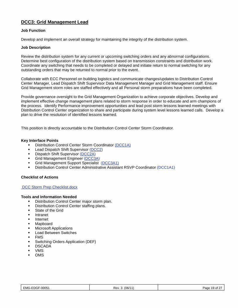
EMG-EDGF-00051 Rev. 3 (06/11) Page 19 of 27
DCC3: Grid Management Lead Job Function Develop and implement an overall strategy for maintaining the integrity of the distribution system. Job Description Review the distribution system for any current or upcoming switching orders and any abnormal configurations. Determine best configuration of the distribution system based on transmission constraints and distribution work. Coordinate any switching that needs to be completed or delayed and initiate return to normal switching for any outstanding orders that may be returned to normal prior to the event. Collaborate with ECC Personnel on building logistics and communicate changes/updates to Distribution Control Center Manager, Lead Dispatch Shift Supervisor Data Management Manager and Grid Management staff. Ensure Grid Management storm roles are staffed effectively and all Personal storm preparations have been completed. Provide governance oversight to the Grid Management Organization to achieve corporate objectives. Develop and implement effective change management plans related to storm response in order to educate and arm champions of the process. Identify Performance improvement opportunities and lead post storm lessons learned meetings with Distribution Control Center organization to share and participate during system level lessons learned calls. Develop a plan to drive the resolution of identified lessons learned. This position is directly accountable to the Distribution Control Center Storm Coordinator. Key Interface Points
Distribution Control Center Storm Coordinator (DCC1A) Lead Dispatch Shift Supervisor (DCC2) Dispatch Shift Supervisor (DCC2A) Grid Management Engineer (DCC3A) Grid Management Support Specialist (DCC3A1) Distribution Control Center Administrative Assistant RSVP Coordinator (DCC1A1)
Checklist of Actions DCC Storm Prep Checklist.docx Tools and Information Needed
Distribution Control Center major storm plan. Distribution Control Center staffing plans. State of the Grid Intranet Internet Mapboard Microsoft Applications Load Between Switches FMS Switching Orders Application (DEF) DSCADA VMS OMS
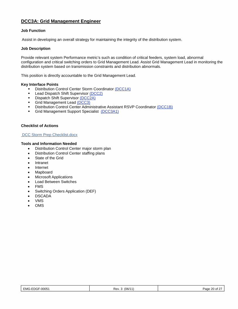
EMG-EDGF-00051 Rev. 3 (06/11) Page 20 of 27
DCC3A: Grid Management Engineer Job Function Assist in developing an overall strategy for maintaining the integrity of the distribution system. Job Description Provide relevant system Performance metric’s such as condition of critical feeders, system load, abnormal configuration and critical switching orders to Grid Management Lead. Assist Grid Management Lead in monitoring the distribution system based on transmission constraints and distribution abnormals. This position is directly accountable to the Grid Management Lead. Key Interface Points
Distribution Control Center Storm Coordinator (DCC1A) Lead Dispatch Shift Supervisor (DCC2) Dispatch Shift Supervisor (DCC2A) Grid Management Lead (DCC3) Distribution Control Center Administrative Assistant RSVP Coordinator (DCC1B) Grid Management Support Specialist (DCC3A1)
Checklist of Actions DCC Storm Prep Checklist.docx Tools and Information Needed
• Distribution Control Center major storm plan • Distribution Control Center staffing plans • State of the Grid • Intranet • Internet • Mapboard • Microsoft Applications • Load Between Switches • FMS • Switching Orders Application (DEF) • DSCADA • VMS • OMS
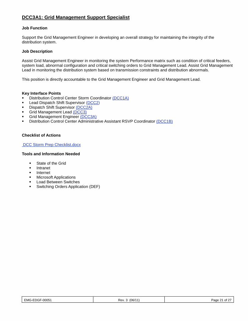
EMG-EDGF-00051 Rev. 3 (06/11) Page 21 of 27
DCC3A1: Grid Management Support Specialist Job Function Support the Grid Management Engineer in developing an overall strategy for maintaining the integrity of the distribution system. Job Description Assist Grid Management Engineer in monitoring the system Performance matrix such as condition of critical feeders, system load, abnormal configuration and critical switching orders to Grid Management Lead. Assist Grid Management Lead in monitoring the distribution system based on transmission constraints and distribution abnormals. This position is directly accountable to the Grid Management Engineer and Grid Management Lead. Key Interface Points Distribution Control Center Storm Coordinator (DCC1A) Lead Dispatch Shift Supervisor (DCC2) Dispatch Shift Supervisor (DCC2A) Grid Management Lead (DCC3) Grid Management Engineer (DCC3A) Distribution Control Center Administrative Assistant RSVP Coordinator (DCC1B)
Checklist of Actions DCC Storm Prep Checklist.docx Tools and Information Needed
State of the Grid Intranet Internet Microsoft Applications Load Between Switches Switching Orders Application (DEF)
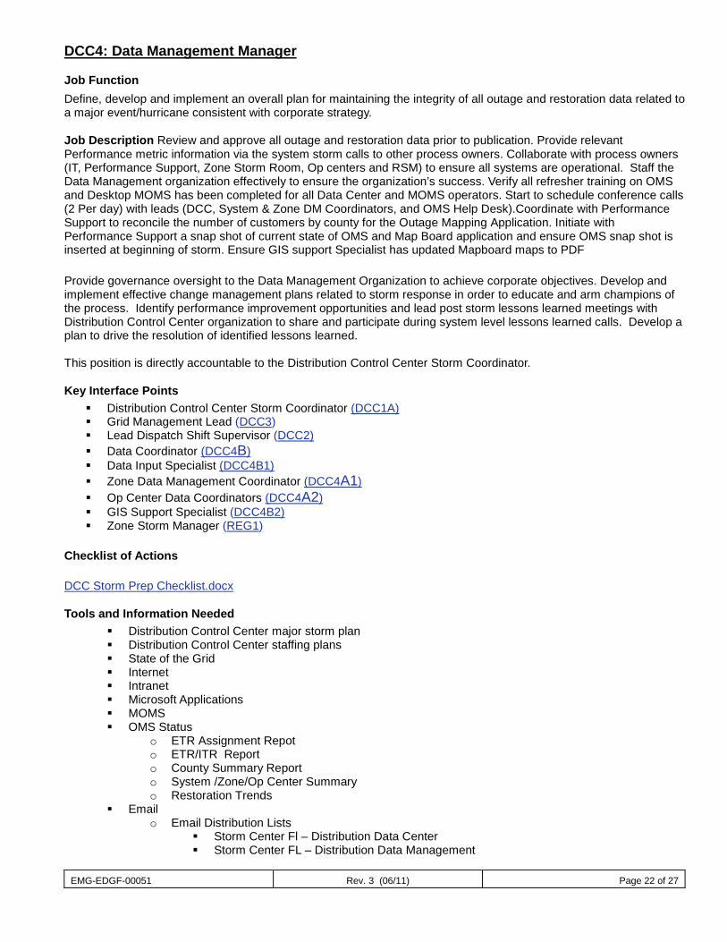
EMG-EDGF-00051 Rev. 3 (06/11) Page 22 of 27
DCC4: Data Management Manager
Job Function Define, develop and implement an overall plan for maintaining the integrity of all outage and restoration data related to a major event/hurricane consistent with corporate strategy.
Job Description Review and approve all outage and restoration data prior to publication. Provide relevant Performance metric information via the system storm calls to other process owners. Collaborate with process owners (IT, Performance Support, Zone Storm Room, Op centers and RSM) to ensure all systems are operational. Staff the Data Management organization effectively to ensure the organization’s success. Verify all refresher training on OMS and Desktop MOMS has been completed for all Data Center and MOMS operators. Start to schedule conference calls (2 Per day) with leads (DCC, System & Zone DM Coordinators, and OMS Help Desk).Coordinate with Performance Support to reconcile the number of customers by county for the Outage Mapping Application. Initiate with Performance Support a snap shot of current state of OMS and Map Board application and ensure OMS snap shot is inserted at beginning of storm. Ensure GIS support Specialist has updated Mapboard maps to PDF
Provide governance oversight to the Data Management Organization to achieve corporate objectives. Develop and implement effective change management plans related to storm response in order to educate and arm champions of the process. Identify performance improvement opportunities and lead post storm lessons learned meetings with Distribution Control Center organization to share and participate during system level lessons learned calls. Develop a plan to drive the resolution of identified lessons learned. This position is directly accountable to the Distribution Control Center Storm Coordinator.
Key Interface Points Distribution Control Center Storm Coordinator (DCC1A) Grid Management Lead (DCC3) Lead Dispatch Shift Supervisor (DCC2) Data Coordinator (DCC4B) Data Input Specialist (DCC4B1) Zone Data Management Coordinator (DCC4A1) Op Center Data Coordinators (DCC4A2) GIS Support Specialist (DCC4B2) Zone Storm Manager (REG1)
Checklist of Actions DCC Storm Prep Checklist.docx
Tools and Information Needed Distribution Control Center major storm plan Distribution Control Center staffing plans State of the Grid Internet Intranet Microsoft Applications MOMS OMS Status
o ETR Assignment Repot o ETR/ITR Report o County Summary Report o System /Zone/Op Center Summary o Restoration Trends
Email o Email Distribution Lists
Storm Center Fl – Distribution Data Center Storm Center FL – Distribution Data Management
EMG-EDGF-00051 Rev. 3 (06/11) Page 23 of 27
DCC4A1: Zone Data Management Coordinator
Job Function Maintain the integrity of all outage and restoration data for the zone(s).
Job Description Compile, Analysis and report accurate outage and restoration information during a major event/hurricane to the Data Management Manager. Collaborate with process owners to ensure accurate modeling of the system. Oversee the zone’s to ensure accurate outage and restoration data. Ensure all employees have a full understanding of the AIRD process and the role they play in executing this process. Maintain a clear understanding of the projected storm path including wind speed, rainfall, storm surge and estimated time of landfall. Make sure this information is communicated to all employees. This position is directly accountable to the Data Management Manager. Key Interface Points
Data Management Manager (DCC4) Operations Center Coordinator (DCC4A2) Grid Management Lead (DCC3) Lead Dispatch Shift Supervisor (DCC2) Zone Storm Manager (REG1) Desktop MOMS Operator (DCC4A3)
Checklist of Actions DCC4A1 Region DM Coordinator
Tools and Information Needed Desktop MOMS Intranet Internet Microsoft Applications AIRD Process ETR OMS Status
o Assignment Repot o ETR/ITR Report o County Summary Report o System /Zone/Op Center Summary o Restoration Trends
Email o Email Distribution Lists
Storm Center Fl – Distribution Data Center Storm Center FL – Distribution Data Management
EMG-EDGF-00051 Rev. 3 (06/11) Page 24 of 27
DCC4A2: Operations Center Coordinator
Job Function This position is responsible for maintain the integrity of all outage and restoration data for the Operations Center.
Job Description This individual is responsible for updating outage data within the MOMS application as necessary during the restoration process. This may include but not be limited to completing outages, adding outage comments, ETR management. This position is directly accountable to the Zone Data Management Coordinator and Data Management Manager.
Key Interface Points Data Management Manager (DCC4) Tactical Management Coordinator (OPS2) Zone Damage Assessment Coordinator (DA2) Zone Data Management Coordinator (DCC4A1)
Checklist of Actions DCC4A2 Op Center Coordinator
Tools and Information Needed Desktop MOMS software Intranet Internet Microsoft Applications Email
o Email Distribution Lists Storm Center Fl – Distribution Data Center Storm Center FL – Distribution Data Management
DCC4A3: MOMS Operator
Job Function This position is responsible for maintaining information in Mobile Outage Management System (MOMS) at the Operating Center.
Job Description This individual is responsible for updating outage data within the MOMS application as necessary during the restoration process. This may include but not be limited to completing outages, adding outage comments, ETR management. This position is directly accountable to the Operations Center Coordinator and Data Management Manager.
Key Interface Points
Data Management Manager (DCC4) Tactical Management Coordinator (OPS2) Zone Damage Assessment Coordinator (DA2) Zone Data Management Coordinator (DCC4A1)
EMG-EDGF-00051 Rev. 3 (06/11) Page 25 of 27
Checklist of Actions DCC4A3 Desktop MOMS Operator Tools and Information Needed
Desktop MOMS software Intranet Internet Microsoft Applications Email
o Email Distribution Lists Storm Center Fl – Distribution Data Center Storm Center FL – Distribution Data Management
DCC4B: Data Coordinator Job Function Maintain the integrity of all outage and restoration data for the Data Management Center. Job Description Compile, Analysis and report accurate outage and restoration information during a major event/hurricane to the Data Management Manager. Collaborate with Process Owners to ensure accurate modeling of the system. Staff the Data Center effectively to ensure the organizations success. Manage the Distribution Control Center Data Center group to ensure accurate outage and restoration data. Ensure all Data Center employees have a full understanding of the AIRD and D1 process and the role they play in executing this process. Maintain a clear understanding of the projected storm path including wind speed, rainfall, storm surge and estimated time of landfall. Make sure this information is communicated to all Distribution Control Center Data Center employees. Communicate any building logistics and possible changes to the Distribution Control Center Data Center employees This position is directly accountable to the Data Management Manager. Key Interface Points
Data Management Manager (DCC4) Operations Center Coordinator (DCC4A2) Grid Management Lead (DCC3) Lead Dispatch Shift Supervisor (DCC2) Zone Storm Manager (REG1) Data Input Specialist (DCC4B1) GIS Support Specialist (DCC4B2)
Checklist of Actions DCC4B Data Coordinator
EMG-EDGF-00051 Rev. 3 (06/11) Page 26 of 27
Tools and Information Needed
Distribution Control Center major storm plan Distribution Control Center staffing plans OMS Intranet Internet Microsoft Applications AIRD Process D1’s Process OMS Status
o ETR Assignment Repot o ETR/ITR Report o County Summary Report o System /Zone/Op Center Summary o Restoration Trends
Email o Email Distribution Lists
Storm Center Fl – Distribution Data Center Storm Center FL – Distribution Data Management
DCC4B1: Data Input Specialist Job Function Monitor and update OMS and Mobil Link work when applicable. Provide real-time modeling of the system in accordance with the AIRD standards to ensure accurate outage and restoration data. Job Description Follow the AIRD process by modeling OMS to reflect the current condition of the distribution system. Process the outage log’s received in the Distribution Data Center by creating confirmed outages in OMS by utilizing the “forced outage creation “process. Monitor and update ETR. Update resource information in OMS. Associate Immediate Problem Tickets with outages. Follow process for voiding 21 & 25 tickets associated with feeder Operations. Update outages with connectivity errors. Assist with creating D1’s when applicable. Perform single outage callbacks when necessary. This position is directly accountable to the Data Coordinator and Data Management Manager. Key Interface Points Data Coordinator (DCC4B) Data Management Manager (DCC4) GIS Support Specialist (DCC4B2) Service Dispatchers (DCC2A3) Associate Distribution Dispatcher (DCC2A4) Checklist of Actions DCC4B1 Data Input Specialist
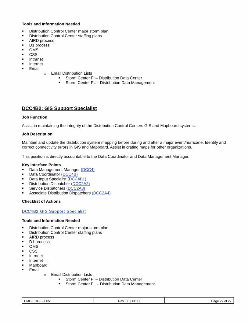
EMG-EDGF-00051 Rev. 3 (06/11) Page 27 of 27
Tools and Information Needed
Distribution Control Center major storm plan Distribution Control Center staffing plans AIRD process D1 process OMS CSS Intranet Internet Email
o Email Distribution Lists Storm Center Fl – Distribution Data Center Storm Center FL – Distribution Data Management
DCC4B2: GIS Support Specialist Job Function Assist in maintaining the integrity of the Distribution Control Centers GIS and Mapboard systems. Job Description Maintain and update the distribution system mapping before during and after a major event/hurricane. Identify and correct connectivity errors in GIS and Mapboard. Assist in crating maps for other organizations. This position is directly accountable to the Data Coordinator and Data Management Manager. Key Interface Points Data Management Manager (DCC4) Data Coordinator (DCC4B) Data Input Specialist (DCC4B1) Distribution Dispatcher (DCC2A2) Service Dispatchers (DCC2A3) Associate Distribution Dispatchers (DCC2A4) Checklist of Actions DCC4B2 GIS Support Specialist Tools and Information Needed
Distribution Control Center major storm plan Distribution Control Center staffing plans AIRD process D1 process OMS CSS Intranet Internet Mapboard Email
o Email Distribution Lists Storm Center Fl – Distribution Data Center Storm Center FL – Distribution Data Management
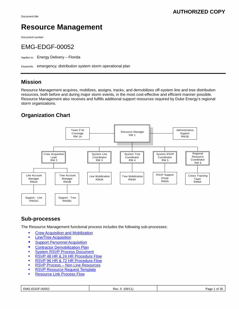
AUTHORIZED COPY
EMG-EDGF-00052 Rev. 5 (09/11) Page 1 of 35
Document title
Resource Management Document number
EMG-EDGF-00052 Applies to: Energy Delivery – Florida Keywords: emergency; distribution system storm operational plan
Mission Resource Management acquires, mobilizes, assigns, tracks, and demobilizes off-system line and tree distribution resources, both before and during major storm events, in the most cost-effective and efficient manner possible. Resource Management also receives and fulfills additional support resources required by Duke Energy’s regional storm organizations.
Organization Chart
Resource ManagerRM 1
Team P.M.Coverage
RM 1A
System TreeCoordinator
RM 4
System RSVPCoordinator
RM 5
System LineCoordinator
RM 3
RegionalResource
CoordinatorRM 6
Crew AcquisitionLeadRM 2
Tree AccountManagerRM2B
Line AccountManager
RM2A
Support - TreeRM2B1
Support - LineRM2A1
Line MobilizationRM3A
Tree MobilizationRM4A
RSVP SupportGroupRM5A
AdministrativeSupportRM1B
Crews TrackingTeamRM6A
Sub-processes The Resource Management functional process includes the following sub-processes:
Crew Acquisition and Mobilization Line/Tree Acquisition Support Personnel Acquisition Contractor Demobilization Plan System RSVP Process Document RSVP 48 HR & 24 HR Procedure Flow RSVP 96 HR & 72 HR Procedure Flow RSVP Process – Non Line Resources RSVP Resource Request Template Resource Link Process Flow

AUTHORIZED COPY
EMG-EDGF-00052 Rev. 5 (09/11) Page 2 of 35
Crew Acquisition and Mobilization This sub-process gathers the information needed to determine and prioritize the amount and type of resources required to support system-wide restoration efforts.
The following personnel are engaged in Crew Acquisition and Mobilization: Resource Manager (RM1) Crew Acquisition Lead (RM2) Distribution System Storm Coordinator (DSSC1) Fleet (FL1) Region Storm Coordinator (REG2) System Staging and Logistics Coordinator (SL1)
The flowchart and timeline below provide a detailed view of this sub-process:
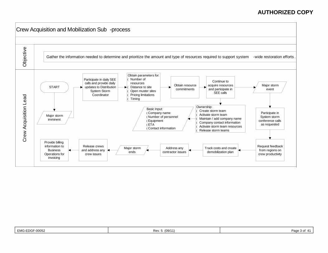
AUTHORIZED COPY
EMG-EDGF-00052 Rev. 5 (09/11) Page 3 of 41
Crew Acquisition and Mobilization Sub -processC
rew
Acq
uisi
tion
Lead
Obj
ectiv
e
Gather the information needed to determine and prioritize the amount and type of resources required to support system -wide restoration efforts .
START
Participate in daily SEE calls and provide daily updates to Distribution
System Storm Coordinator
Obtain parameters for:( Number of
resources( Distance to site( Open muster sites( Pricing limitations( Timing
Obtain resource commitments
Continue to acquire resources and participate in
SEE calls
Major storm imminent
Ownership:( Create storm team( Activate storm team( Maintain / add company name( Company contact information( Activate storm team resources( Release storm teams
Basic Input:(Company name(Number of personnel(Equipment(ETA (Contact information
Major storm event
Participate in System storm
conference calls as requested
Request feedback from regions on crew productivity
Track costs and create demobilization plan
Address any contractor issues
Major storm ends
Release crews and address any
crew issues
Provide billing information to
Business Operations for
invoicing
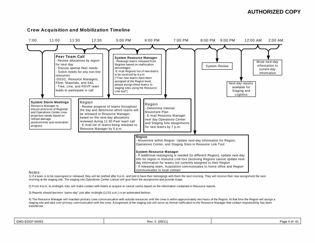
AUTHORIZED COPY
EMG-EDGF-00052 Rev. 5 (09/11) Page 4 of 41
System Storm MeetingsResource Manager toensure provision of Regionaland Operations Center crewprojection needs based onrefined damageassessments and restorationprogress
Peer Team Call- Review allocations by regionfor next day- Discuss special fleet needs- Solicit needs for any non-lineresources-DSSC, Resource Managers,Fleet, Materials, and S&L- Tree, Line, and RSVP teamleads to participate in call
Region- Review progress of teams throughoutthe day and determine which teams willbe released to Resource Manager,based on the next-day allocationsreviewed during 11:30 Peer team call- E-mail list of teams being released toResource Manager by 5 p.m.
System Resource Manager- Reassign teams released fromRegions based on reallocationpercentages.-E-mail Regions list of new teamsto be received by 6 p.m(“Your new teams have beenassigned at the Region level,please assign these teams tostaging sites using the ResourceLink tool”)
Region- Determine InternalMovement Plan- E-mail Resource Managernext day Operations Centerand Staging Site assignmentsfor new teams by 7 p.m.
Region- Movement within Region: Update next-day information for Region,Operations Center, and Staging Sites in Resource Link Tool
System Resource Manager- If additional reassigning is needed (to different Region), update next-dayinfo for region in resource Link tool (receiving Regions cannot update next-day information for teams not currently assigned to their Region- If releasing team, Acquisition communicates to home office and Regioncommunicates to local contact
System ReviewMove next-dayinformation to
current-dayinformation
Next-day reportsavailable forStaging and
Logistics
7:00 11:00 11:30 12:30 5:00 PM 6:00 PM 7:00 PM 8:00 PM 9:00 PM 12:00 AM 2:00 AM
Crew Acquisition and Mobilization Timeline
Notes:1) If a team is to be reassigned or released, they will be notified after 6 p.m. and told to have their belongings with them the next morning. They will receive their new assignment the nextmorning at the staging site. The staging site Operations Center Liaison will give them the assignment and provide maps.
2) From 9 p.m. to midnight, S&L will make contact with hotels to acquire or cancel rooms based on the information contained in Resource reports.
3) Reports should become “same-day” just after midnight (12:01 a.m.) in an automated fashion.
4) The Resource Manager will maintain primary crew communication with outside resources until the crew is within approximately two hours of the Region. At that time the Region will assign astaging site and take over primary communication with the crew. Assignment of the staging site will serve as formal notification to the Resource Manager that contact responsibility has beentransferred.
AUTHORIZED COPY
EMG-EDGF-00052 Rev. 5 (09/11) Page 5 of 41
Line/Tree Acquisition The Line/Tree Acquisition sub-process determines the movement of line and tree crews during restoration efforts.
The following personnel are engaged in Line/Tree Acquisition: Resource Manager (RM1) System Line Coordinator (RM3) System Tree Coordinator (RM4) Team P.M. Coverage (RM1A)
The timeline below provides a detailed view of this sub-process:
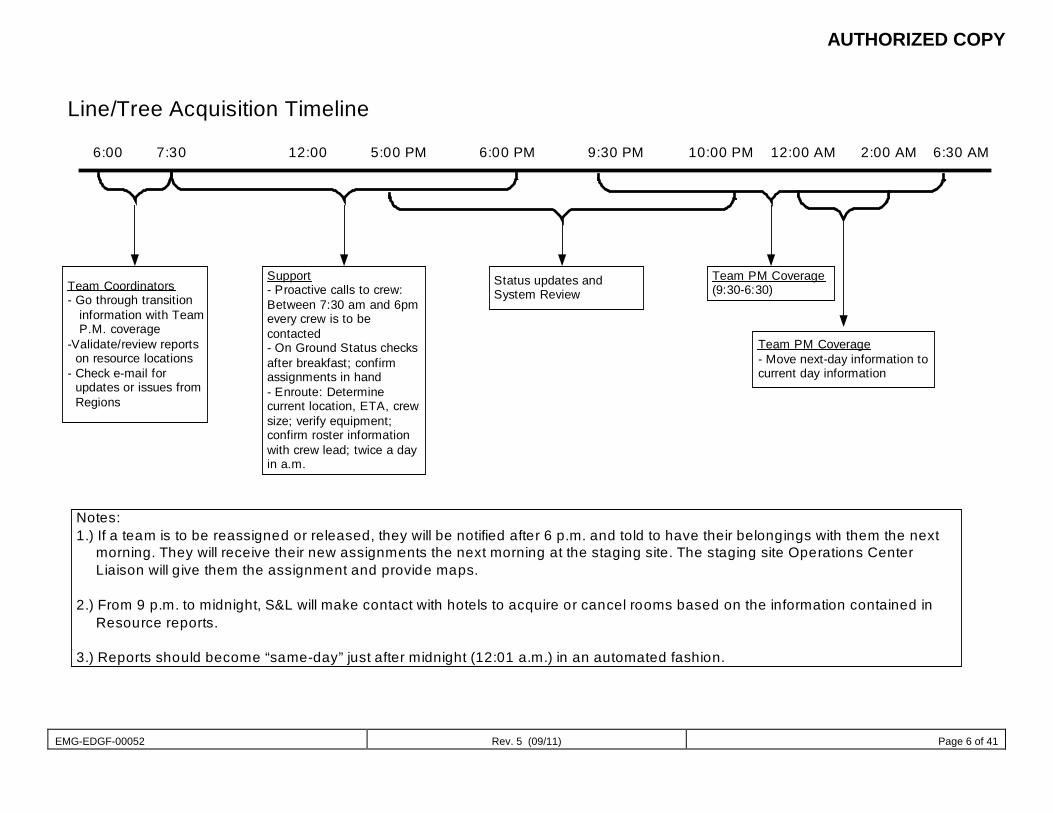
AUTHORIZED COPY
EMG-EDGF-00052 Rev. 5 (09/11) Page 6 of 41
Line/Tree Acquisition Timeline
6:00 7:30 12:00 5:00 PM 6:00 PM 9:30 PM 6:30 AM2:00 AM12:00 AM10:00 PM
Team Coordinators- Go through transition information with Team P.M. coverage-Validate/review reports on resource locations- Check e-mail for updates or issues from Regions
Support- Proactive calls to crew:Between 7:30 am and 6pmevery crew is to becontacted- On Ground Status checksafter breakfast; confirmassignments in hand- Enroute: Determinecurrent location, ETA, crewsize; verify equipment;confirm roster informationwith crew lead; twice a dayin a.m.
Status updates andSystem Review
Team PM Coverage(9:30-6:30)
Team PM Coverage- Move next-day information tocurrent day information
Notes:1.) If a team is to be reassigned or released, they will be notified after 6 p.m. and told to have their belongings with them the next morning. They will receive their new assignments the next morning at the staging site. The staging site Operations Center Liaison will give them the assignment and provide maps.
2.) From 9 p.m. to midnight, S&L will make contact with hotels to acquire or cancel rooms based on the information contained in Resource reports.
3.) Reports should become “same-day” just after midnight (12:01 a.m.) in an automated fashion.
AUTHORIZED COPY
EMG-EDGF-00052 Rev. 5 (09/11) Page 7 of 28
Support Personnel Acquisition The Support Personnel Acquisition sub-process determines the needs for support personnel other than line and tree.
The following personnel are engaged in Support Personnel Acquisition: Generation Resource Manager (RM1) System RSVP Coordinator (Non-line) (RM5) Team P.M. Coverage (RM1A)
The timeline below provides a detailed view of this sub-process:
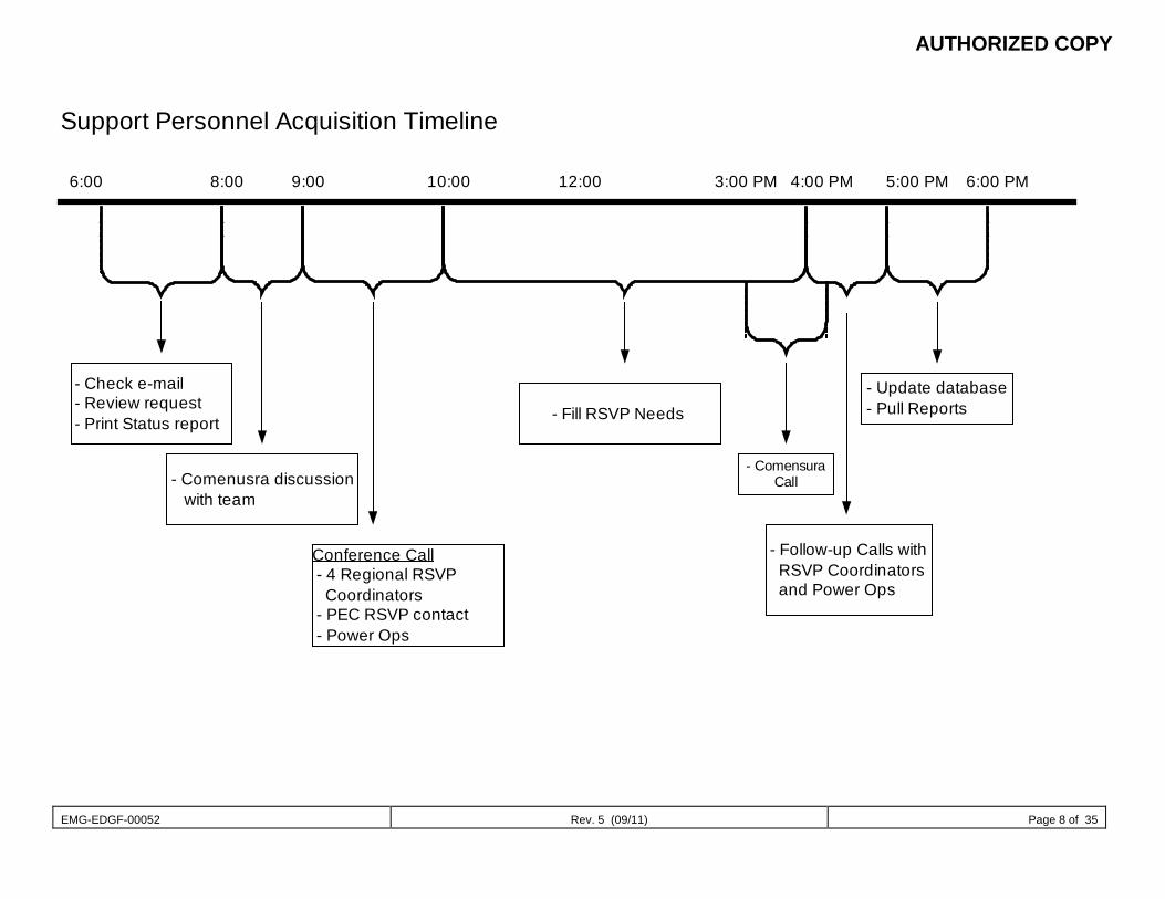
AUTHORIZED COPY
EMG-EDGF-00052 Rev. 5 (09/11) Page 8 of 35
- Check e-mail - Review request - Print Status report - Fill RSVP Needs
- ComensuraCall
- Follow-up Calls with RSVP Coordinators and Power Ops
- Update database - Pull Reports
- Comenusra discussion with team
Conference Call - 4 Regional RSVP Coordinators - PEC RSVP contact - Power Ops
6:00 8:00 9:00 10:00 12:00 4:00 PM3:00 PM 5:00 PM 6:00 PM
Support Personnel Acquisition Timeline

AUTHORIZED COPY
EMG-EDGF-00052 Rev. 5 (09/11) Page 9 of 41
Tree Ground Acquisition The Tree Ground Acquisition sub-process determines the needs for grounds to support contract tree personnel assisting in restoration efforts.
The following personnel are engaged in Tree Ground Acquisition: Crew Acquisition Lead (RM2) Tree Mobilization Lead (RM4A) System Stores Tree Account Manager (RM2B)
The flowchart below provides a detailed view of this sub-process:
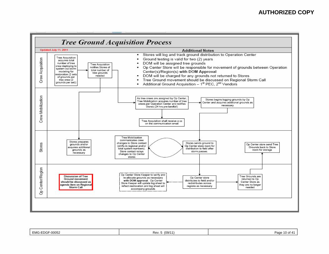
AUTHORIZED COPY
EMG-EDGF-00052 Rev. 5 (09/11) Page 10 of 41
AUTHORIZED COPY
EMG-EDGF-00052 Rev. 5 (09/11) Page 11 of 41
Contractor Demobilization Plan The Contractor Demobilization Plan sub-process outlines the systematic release of contractor (line and tree) as restoration efforts necessitate.
The following personnel are engaged in Tree Ground Acquisition: Resource Manager (RM1) Crew Acquisition Lead (RM2) Tree Mobilization (RM4A) Line Mobilization (RM3A) Tree Account Manager (RM2B) Line Account Manager (RM3A) Region Resource Coordinator (RM6) Zone Coordinator (OPS2C-2C1) RM Coordinator (OPS3)
The documents for current storm can be accessed by clicking here (restricted access). The flowchart below provides a detailed view of this sub-process:
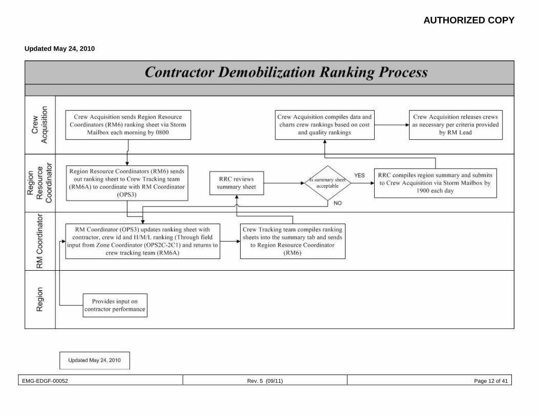
AUTHORIZED COPY
EMG-EDGF-00052 Rev. 5 (09/11) Page 12 of 41
Updated May 24, 2010
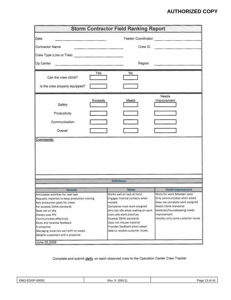
AUTHORIZED COPY
EMG-EDGF-00052 Rev. 5 (09/11) Page 13 of 41
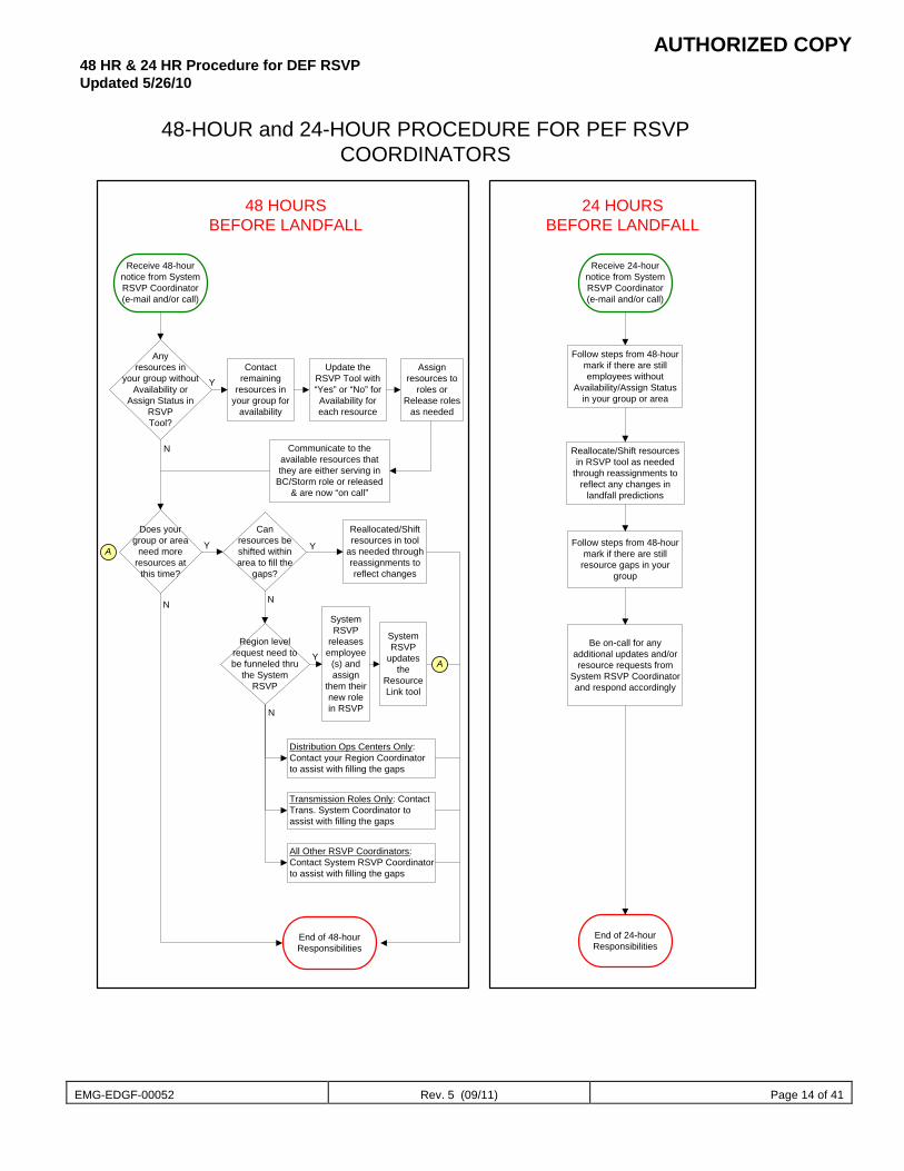
AUTHORIZED COPY
EMG-EDGF-00052 Rev. 5 (09/11) Page 14 of 41
48 HR & 24 HR Procedure for DEF RSVP Updated 5/26/10
Receive 48-hournotice from SystemRSVP Coordinator(e-mail and/or call)
Receive 24-hournotice from SystemRSVP Coordinator(e-mail and/or call)
48-HOUR and 24-HOUR PROCEDURE FOR PEF RSVPCOORDINATORS
48 HOURSBEFORE LANDFALL
24 HOURSBEFORE LANDFALL
End of 24-hourResponsibilities
Anyresources in
your group withoutAvailability or
Assign Status inRSVPTool?
Contactremaining
resources inyour group for
availability
Update theRSVP Tool with“Yes” or “No” forAvailability foreach resource
Assignresources to
roles orRelease roles
as needed
Communicate to theavailable resources thatthey are either serving in
BC/Storm role or released& are now “on call”
N
Y
Does yourgroup or area
need moreresources at
this time?
Canresources beshifted withinarea to fill the
gaps?
Reallocated/Shiftresources in tool
as needed throughreassignments toreflect changes
Distribution Ops Centers Only:Contact your Region Coordinatorto assist with filling the gaps
Transmission Roles Only: ContactTrans. System Coordinator toassist with filling the gaps
All Other RSVP Coordinators:Contact System RSVP Coordinatorto assist with filling the gaps
End of 48-hourResponsibilities
N
Y Y
N
SystemRSVP
releasesemployee
(s) andassign
them theirnew rolein RSVP
Region levelrequest need tobe funneled thru
the SystemRSVP
Y
N
A
A
Follow steps from 48-hourmark if there are stillemployees without
Availability/Assign Statusin your group or area
Follow steps from 48-hourmark if there are still
resource gaps in yourgroup
Be on-call for anyadditional updates and/orresource requests from
System RSVP Coordinatorand respond accordingly
Reallocate/Shift resourcesin RSVP tool as needed
through reassignments toreflect any changes in
landfall predictions
SystemRSVP
updatesthe
ResourceLink tool
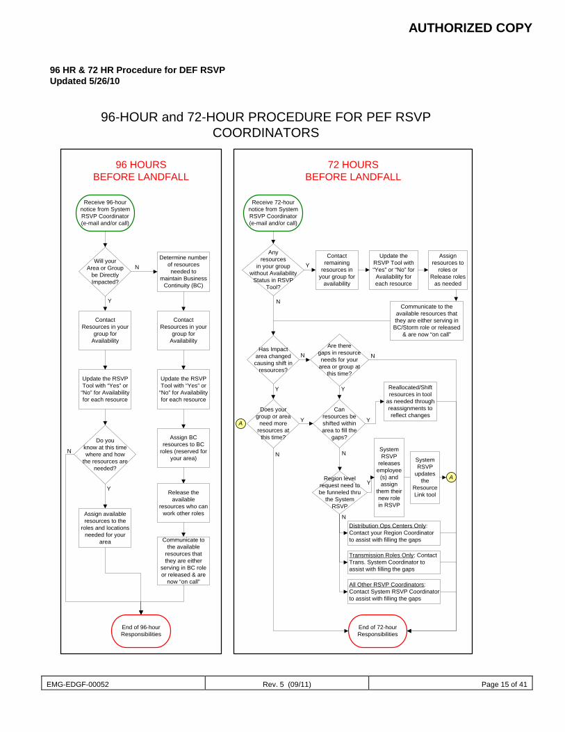
AUTHORIZED COPY
EMG-EDGF-00052 Rev. 5 (09/11) Page 15 of 41
96 HR & 72 HR Procedure for DEF RSVP Updated 5/26/10
Receive 96-hournotice from SystemRSVP Coordinator(e-mail and/or call)
ContactResources in your
group forAvailability
Update the RSVPTool with “Yes” or“No” for Availabilityfor each resource
Assign availableresources to the
roles and locationsneeded for your
area
Will yourArea or Group
be DirectlyImpacted?
Do youknow at this timewhere and how
the resources areneeded?
Determine numberof resourcesneeded to
maintain BusinessContinuity (BC)
End of 96-hourResponsibilities
ContactResources in your
group forAvailability
Update the RSVPTool with “Yes” or“No” for Availabilityfor each resource
Assign BCresources to BC
roles (reserved foryour area)
Release theavailable
resources who canwork other roles
Communicate tothe available
resources thatthey are either
serving in BC roleor released & are
now “on call”
Receive 72-hournotice from SystemRSVP Coordinator(e-mail and/or call)
Anyresources
in your groupwithout Availability
Status in RSVPTool?
Has Impactarea changedcausing shift in
resources?
Does yourgroup or area
need moreresources at
this time?
Are theregaps in resourceneeds for your
area or group atthis time?
Canresources beshifted withinarea to fill the
gaps?
Contactremaining
resources inyour group for
availability
Update theRSVP Tool with“Yes” or “No” forAvailability foreach resource
Assignresources to
roles orRelease roles
as needed
Communicate to theavailable resources thatthey are either serving in
BC/Storm role or released& are now “on call”
Reallocated/Shiftresources in tool
as needed throughreassignments toreflect changes
Distribution Ops Centers Only:Contact your Region Coordinatorto assist with filling the gaps
Transmission Roles Only: ContactTrans. System Coordinator toassist with filling the gaps
All Other RSVP Coordinators:Contact System RSVP Coordinatorto assist with filling the gaps
End of 72-hourResponsibilities
96-HOUR and 72-HOUR PROCEDURE FOR PEF RSVPCOORDINATORS
96 HOURSBEFORE LANDFALL
72 HOURSBEFORE LANDFALL
N
Y
N
Y
N
Y
N
Y
N
Y
N
Y Y
N
Region levelrequest need tobe funneled thru
the SystemRSVP
SystemRSVP
releasesemployee
(s) andassign
them theirnew rolein RSVP
Y
N
A
A
SystemRSVP
updatesthe
ResourceLink tool
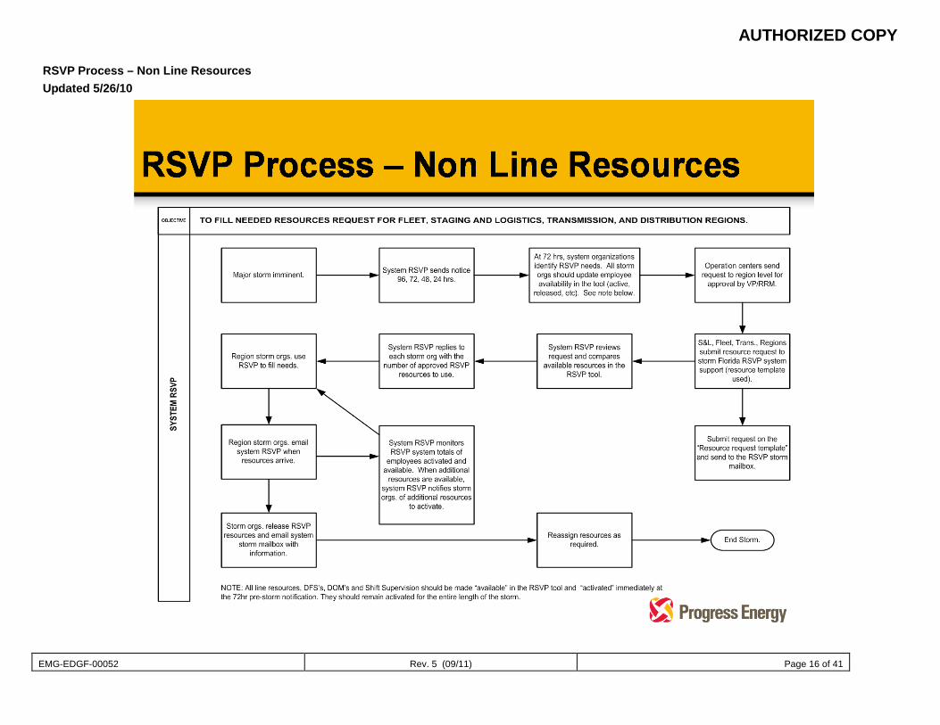
AUTHORIZED COPY
EMG-EDGF-00052 Rev. 5 (09/11) Page 16 of 41
RSVP Process – Non Line Resources Updated 5/26/10
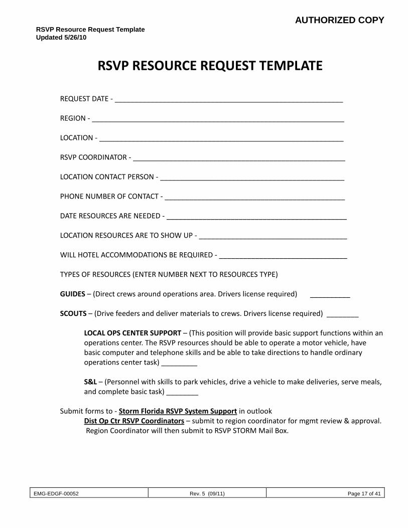
AUTHORIZED COPY
EMG-EDGF-00052 Rev. 5 (09/11) Page 17 of 41
RSVP Resource Request Template Updated 5/26/10
RSVP RESOURCE REQUEST TEMPLATE
REQUEST DATE - _________________________________________________________
REGION - _______________________________________________________________
LOCATION - _____________________________________________________________
RSVP COORDINATOR - _____________________________________________________
LOCATION CONTACT PERSON - ______________________________________________
PHONE NUMBER OF CONTACT - _____________________________________________
DATE RESOURCES ARE NEEDED - _____________________________________________
LOCATION RESOURCES ARE TO SHOW UP - _____________________________________
WILL HOTEL ACCOMMODATIONS BE REQUIRED - ________________________________
TYPES OF RESOURCES (ENTER NUMBER NEXT TO RESOURCES TYPE) GUIDES – (Direct crews around operations area. Drivers license required) __________
SCOUTS – (Drive feeders and deliver materials to crews. Drivers license required) ________
LOCAL OPS CENTER SUPPORT – (This position will provide basic support functions within an operations center. The RSVP resources should be able to operate a motor vehicle, have basic computer and telephone skills and be able to take directions to handle ordinary operations center task) _________
S&L – (Personnel with skills to park vehicles, drive a vehicle to make deliveries, serve meals, and complete basic task) ________
Submit forms to - Storm Florida RSVP System Support in outlook
Dist Op Ctr RSVP Coordinators – submit to region coordinator for mgmt review & approval. Region Coordinator will then submit to RSVP STORM Mail Box.
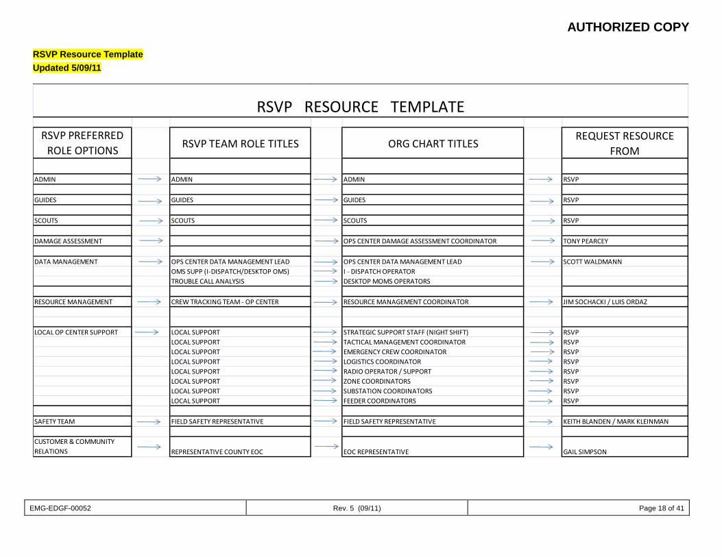
AUTHORIZED COPY
EMG-EDGF-00052 Rev. 5 (09/11) Page 18 of 41
RSVP Resource Template Updated 5/09/11
RSVP PREFERRED ROLE OPTIONS RSVP TEAM ROLE TITLES ORG CHART TITLES
REQUEST RESOURCE FROM
ADMIN ADMIN ADMIN RSVP
GUIDES GUIDES GUIDES RSVP
SCOUTS SCOUTS SCOUTS RSVP
DAMAGE ASSESSMENT OPS CENTER DAMAGE ASSESSMENT COORDINATOR TONY PEARCEY
DATA MANAGEMENT OPS CENTER DATA MANAGEMENT LEAD OPS CENTER DATA MANAGEMENT LEAD SCOTT WALDMANNOMS SUPP (I-DISPATCH/DESKTOP OMS) I - DISPATCH OPERATORTROUBLE CALL ANALYSIS DESKTOP MOMS OPERATORS
RESOURCE MANAGEMENT CREW TRACKING TEAM - OP CENTER RESOURCE MANAGEMENT COORDINATOR JIM SOCHACKI / LUIS ORDAZ
LOCAL OP CENTER SUPPORT LOCAL SUPPORT STRATEGIC SUPPORT STAFF (NIGHT SHIFT) RSVPLOCAL SUPPORT TACTICAL MANAGEMENT COORDINATOR RSVPLOCAL SUPPORT EMERGENCY CREW COORDINATOR RSVPLOCAL SUPPORT LOGISTICS COORDINATOR RSVPLOCAL SUPPORT RADIO OPERATOR / SUPPORT RSVPLOCAL SUPPORT ZONE COORDINATORS RSVPLOCAL SUPPORT SUBSTATION COORDINATORS RSVPLOCAL SUPPORT FEEDER COORDINATORS RSVP
SAFETY TEAM FIELD SAFETY REPRESENTATIVE FIELD SAFETY REPRESENTATIVE KEITH BLANDEN / MARK KLEINMAN
CUSTOMER & COMMUNITY RELATIONS REPRESENTATIVE COUNTY EOC EOC REPRESENTATIVE GAIL SIMPSON
RSVP RESOURCE TEMPLATE
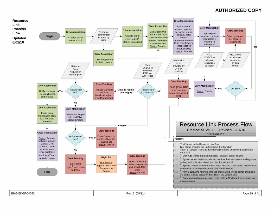
AUTHORIZED COPY
EMG-EDGF-00052 Rev. 5 (09/11) Page 19 of 41
Resource Link Process Flow Updated 6/01/10
Crew Acquisition
Creates storm name in tool
Notes� “Tool” refers to the Resource Link Tool� Tool status changes are underlined in the flow chart� “Next” & “Current” refers to the information found under the Location box
in the tool�� 1 Only Add teams that do not appear in Master List of Teams�� 2 System arrival date/time refers to the time the crews start traveling to our
territory and is located above the blue line in the tool�� 3 System release date/time refers to the time the crews arrive to their home
location and is located above the blue line in the tool�� 4 Arrival date/time refers to time the crews arrive to ops center or staging
site and is located below the blue line in the Current box�� 5 Crew tracking team only enter region field in Next box if crew is staying
in same region
Resource commitment is made by
RM1
Crew Acquisition
Activate storm teams in tool1;
Status: Committed
RM1/DSSC1 to allocate
resources by region
Crew Mobilization
Split teams & rosters, input est personnel, equip,
contact, hotel needs,
communicate team ID to crew leaders;
Track location (manual GPS)Status: Enroute
Crew Acquisition
Call & get crews on the road; input
system arrival date & time2, add ETA in comment box;Status: Enroute
Crew Mobilization
Input region location; continue
manual GPS tracking in comments
Begin
Crew Acquisition
Call company HQ & obtain rosters
Crew Tracking
Enter ops center, LS center & staging site
REG1/RM6 to allocate resources
by ops center
Crew Mobilization
Status: On siteOn Site?Yes
No
Crew Tracking
Insert arrival date/time4; update
actual personnel & equip
Information to be
provided by OPS3A position
Resources to be reallocated?
RM1/DSSC1 to evaluate ETR; vet
with REG1
Crew Tracking
Release via email to Crew
Mobilization (incl crew ID numbers)
Outside region (overnight)
Release from PEF?
Refer to Crew
Acquisition demob plan
Crew Acquisition
Notify company HQ to call crews
and release
Yes
Crew Acquisition
Email Crew Mobilization crew
ID’s that were released
Crew Mobilization
Status: ReleaseValidate release;
Manual GPS crews to home location; insert system release
date & time3 upon arrival to home
Crew Mobilization
Insert Next Region info and ETA;
Status: Enroute
No
Arrive same day?
Crew Tracking
Enter Current ops center, LS center,
staging siteStatus: On site
Yes
Crew Tracking
Enter Next region5, ops center
and ETA
No
Night RM
Run/archive reports; move info
from Next to Current
Crew Tracking
Enter Current LS center, staging site
and arrival date/time;
Status: On Site
In region Resource Link Process FlowCreated: 5/12/10 | Revised: 6/01/10
Version 2.1
End
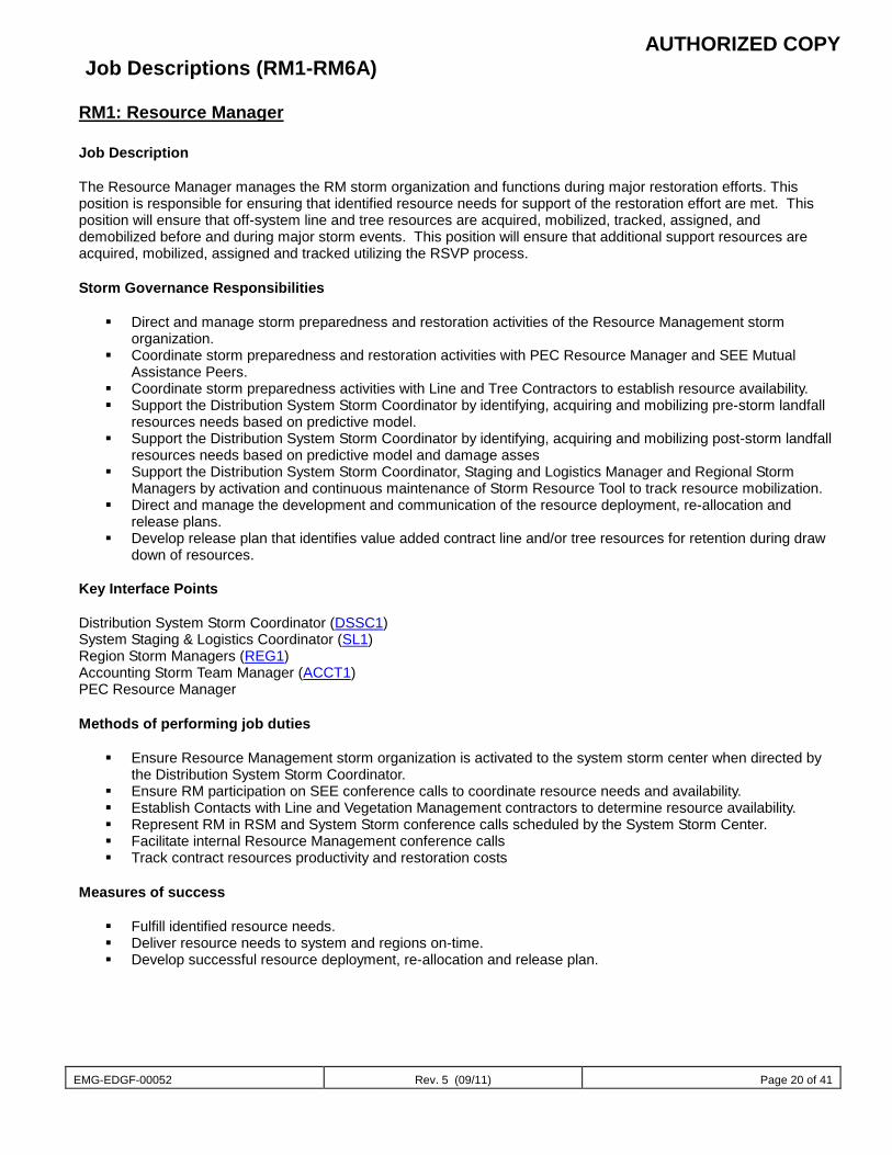
AUTHORIZED COPY
EMG-EDGF-00052 Rev. 5 (09/11) Page 20 of 41
Job Descriptions (RM1-RM6A)
RM1: Resource Manager Job Description The Resource Manager manages the RM storm organization and functions during major restoration efforts. This position is responsible for ensuring that identified resource needs for support of the restoration effort are met. This position will ensure that off-system line and tree resources are acquired, mobilized, tracked, assigned, and demobilized before and during major storm events. This position will ensure that additional support resources are acquired, mobilized, assigned and tracked utilizing the RSVP process. Storm Governance Responsibilities
Direct and manage storm preparedness and restoration activities of the Resource Management storm organization.
Coordinate storm preparedness and restoration activities with PEC Resource Manager and SEE Mutual Assistance Peers.
Coordinate storm preparedness activities with Line and Tree Contractors to establish resource availability. Support the Distribution System Storm Coordinator by identifying, acquiring and mobilizing pre-storm landfall
resources needs based on predictive model. Support the Distribution System Storm Coordinator by identifying, acquiring and mobilizing post-storm landfall
resources needs based on predictive model and damage asses Support the Distribution System Storm Coordinator, Staging and Logistics Manager and Regional Storm
Managers by activation and continuous maintenance of Storm Resource Tool to track resource mobilization. Direct and manage the development and communication of the resource deployment, re-allocation and
release plans. Develop release plan that identifies value added contract line and/or tree resources for retention during draw
down of resources.
Key Interface Points Distribution System Storm Coordinator (DSSC1) System Staging & Logistics Coordinator (SL1) Region Storm Managers (REG1) Accounting Storm Team Manager (ACCT1) PEC Resource Manager Methods of performing job duties
Ensure Resource Management storm organization is activated to the system storm center when directed by the Distribution System Storm Coordinator.
Ensure RM participation on SEE conference calls to coordinate resource needs and availability. Establish Contacts with Line and Vegetation Management contractors to determine resource availability. Represent RM in RSM and System Storm conference calls scheduled by the System Storm Center. Facilitate internal Resource Management conference calls Track contract resources productivity and restoration costs
Measures of success
Fulfill identified resource needs. Deliver resource needs to system and regions on-time. Develop successful resource deployment, re-allocation and release plan.
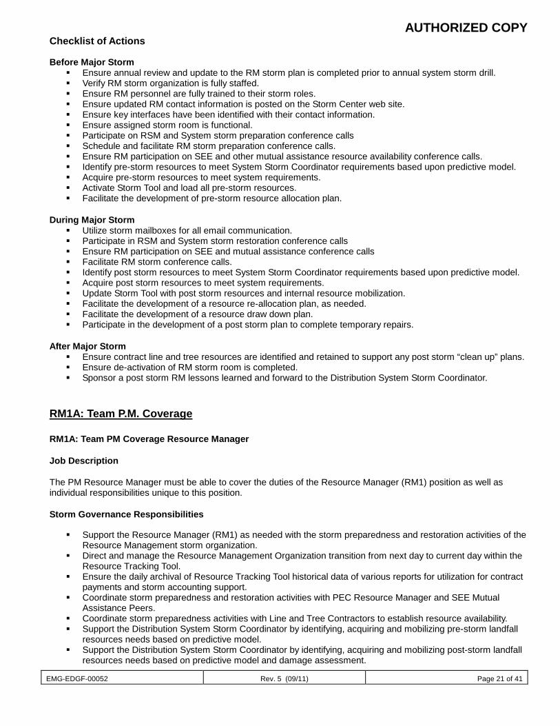
AUTHORIZED COPY
EMG-EDGF-00052 Rev. 5 (09/11) Page 21 of 41
Checklist of Actions Before Major Storm
Ensure annual review and update to the RM storm plan is completed prior to annual system storm drill. Verify RM storm organization is fully staffed. Ensure RM personnel are fully trained to their storm roles. Ensure updated RM contact information is posted on the Storm Center web site. Ensure key interfaces have been identified with their contact information. Ensure assigned storm room is functional. Participate on RSM and System storm preparation conference calls Schedule and facilitate RM storm preparation conference calls. Ensure RM participation on SEE and other mutual assistance resource availability conference calls. Identify pre-storm resources to meet System Storm Coordinator requirements based upon predictive model. Acquire pre-storm resources to meet system requirements. Activate Storm Tool and load all pre-storm resources. Facilitate the development of pre-storm resource allocation plan.
During Major Storm
Utilize storm mailboxes for all email communication. Participate in RSM and System storm restoration conference calls Ensure RM participation on SEE and mutual assistance conference calls Facilitate RM storm conference calls. Identify post storm resources to meet System Storm Coordinator requirements based upon predictive model. Acquire post storm resources to meet system requirements. Update Storm Tool with post storm resources and internal resource mobilization. Facilitate the development of a resource re-allocation plan, as needed. Facilitate the development of a resource draw down plan. Participate in the development of a post storm plan to complete temporary repairs.
After Major Storm
Ensure contract line and tree resources are identified and retained to support any post storm “clean up” plans. Ensure de-activation of RM storm room is completed. Sponsor a post storm RM lessons learned and forward to the Distribution System Storm Coordinator.
RM1A: Team P.M. Coverage RM1A: Team PM Coverage Resource Manager Job Description The PM Resource Manager must be able to cover the duties of the Resource Manager (RM1) position as well as individual responsibilities unique to this position. Storm Governance Responsibilities
Support the Resource Manager (RM1) as needed with the storm preparedness and restoration activities of the Resource Management storm organization.
Direct and manage the Resource Management Organization transition from next day to current day within the Resource Tracking Tool.
Ensure the daily archival of Resource Tracking Tool historical data of various reports for utilization for contract payments and storm accounting support.
Coordinate storm preparedness and restoration activities with PEC Resource Manager and SEE Mutual Assistance Peers.
Coordinate storm preparedness activities with Line and Tree Contractors to establish resource availability. Support the Distribution System Storm Coordinator by identifying, acquiring and mobilizing pre-storm landfall
resources needs based on predictive model. Support the Distribution System Storm Coordinator by identifying, acquiring and mobilizing post-storm landfall
resources needs based on predictive model and damage assessment.
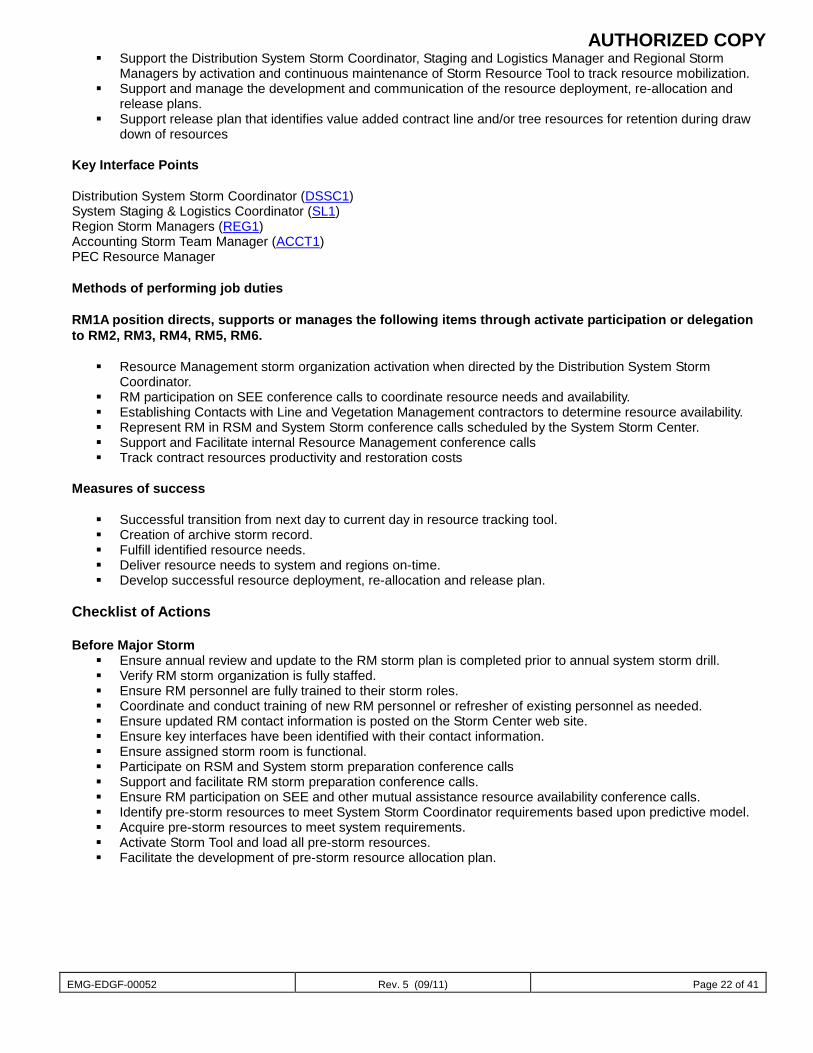
AUTHORIZED COPY
EMG-EDGF-00052 Rev. 5 (09/11) Page 22 of 41
Support the Distribution System Storm Coordinator, Staging and Logistics Manager and Regional Storm Managers by activation and continuous maintenance of Storm Resource Tool to track resource mobilization.
Support and manage the development and communication of the resource deployment, re-allocation and release plans.
Support release plan that identifies value added contract line and/or tree resources for retention during draw down of resources
Key Interface Points Distribution System Storm Coordinator (DSSC1) System Staging & Logistics Coordinator (SL1) Region Storm Managers (REG1) Accounting Storm Team Manager (ACCT1) PEC Resource Manager Methods of performing job duties RM1A position directs, supports or manages the following items through activate participation or delegation to RM2, RM3, RM4, RM5, RM6.
Resource Management storm organization activation when directed by the Distribution System Storm Coordinator.
RM participation on SEE conference calls to coordinate resource needs and availability. Establishing Contacts with Line and Vegetation Management contractors to determine resource availability. Represent RM in RSM and System Storm conference calls scheduled by the System Storm Center. Support and Facilitate internal Resource Management conference calls Track contract resources productivity and restoration costs
Measures of success
Successful transition from next day to current day in resource tracking tool. Creation of archive storm record. Fulfill identified resource needs. Deliver resource needs to system and regions on-time. Develop successful resource deployment, re-allocation and release plan.
Checklist of Actions Before Major Storm
Ensure annual review and update to the RM storm plan is completed prior to annual system storm drill. Verify RM storm organization is fully staffed. Ensure RM personnel are fully trained to their storm roles. Coordinate and conduct training of new RM personnel or refresher of existing personnel as needed. Ensure updated RM contact information is posted on the Storm Center web site. Ensure key interfaces have been identified with their contact information. Ensure assigned storm room is functional. Participate on RSM and System storm preparation conference calls Support and facilitate RM storm preparation conference calls. Ensure RM participation on SEE and other mutual assistance resource availability conference calls. Identify pre-storm resources to meet System Storm Coordinator requirements based upon predictive model. Acquire pre-storm resources to meet system requirements. Activate Storm Tool and load all pre-storm resources. Facilitate the development of pre-storm resource allocation plan.
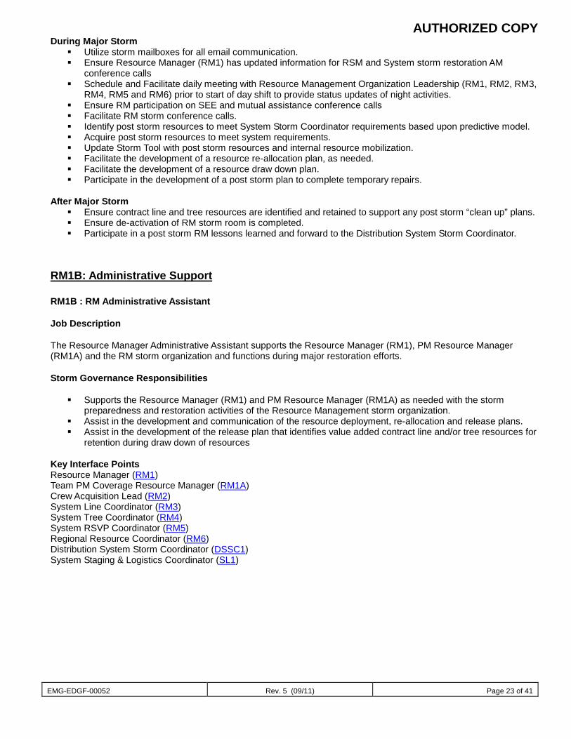
AUTHORIZED COPY
EMG-EDGF-00052 Rev. 5 (09/11) Page 23 of 41
During Major Storm Utilize storm mailboxes for all email communication. Ensure Resource Manager (RM1) has updated information for RSM and System storm restoration AM
conference calls Schedule and Facilitate daily meeting with Resource Management Organization Leadership (RM1, RM2, RM3,
RM4, RM5 and RM6) prior to start of day shift to provide status updates of night activities. Ensure RM participation on SEE and mutual assistance conference calls Facilitate RM storm conference calls. Identify post storm resources to meet System Storm Coordinator requirements based upon predictive model. Acquire post storm resources to meet system requirements. Update Storm Tool with post storm resources and internal resource mobilization. Facilitate the development of a resource re-allocation plan, as needed. Facilitate the development of a resource draw down plan. Participate in the development of a post storm plan to complete temporary repairs.
After Major Storm
Ensure contract line and tree resources are identified and retained to support any post storm “clean up” plans. Ensure de-activation of RM storm room is completed. Participate in a post storm RM lessons learned and forward to the Distribution System Storm Coordinator.
RM1B: Administrative Support RM1B : RM Administrative Assistant Job Description The Resource Manager Administrative Assistant supports the Resource Manager (RM1), PM Resource Manager (RM1A) and the RM storm organization and functions during major restoration efforts. Storm Governance Responsibilities
Supports the Resource Manager (RM1) and PM Resource Manager (RM1A) as needed with the storm preparedness and restoration activities of the Resource Management storm organization.
Assist in the development and communication of the resource deployment, re-allocation and release plans. Assist in the development of the release plan that identifies value added contract line and/or tree resources for
retention during draw down of resources Key Interface Points Resource Manager (RM1) Team PM Coverage Resource Manager (RM1A) Crew Acquisition Lead (RM2) System Line Coordinator (RM3) System Tree Coordinator (RM4) System RSVP Coordinator (RM5) Regional Resource Coordinator (RM6) Distribution System Storm Coordinator (DSSC1) System Staging & Logistics Coordinator (SL1)
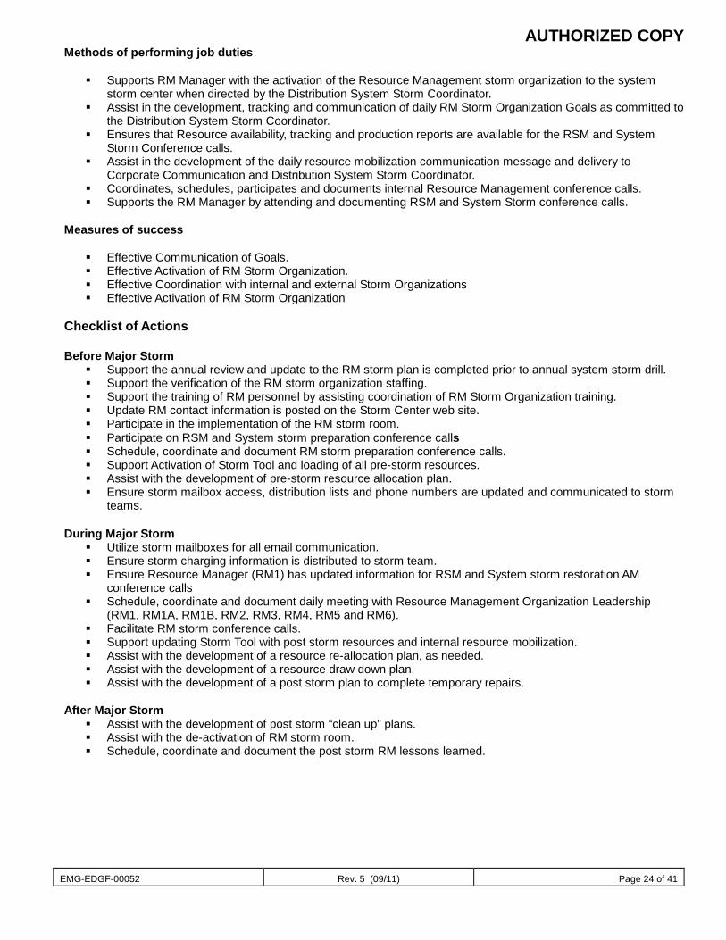
AUTHORIZED COPY
EMG-EDGF-00052 Rev. 5 (09/11) Page 24 of 41
Methods of performing job duties
Supports RM Manager with the activation of the Resource Management storm organization to the system storm center when directed by the Distribution System Storm Coordinator.
Assist in the development, tracking and communication of daily RM Storm Organization Goals as committed to the Distribution System Storm Coordinator.
Ensures that Resource availability, tracking and production reports are available for the RSM and System Storm Conference calls.
Assist in the development of the daily resource mobilization communication message and delivery to Corporate Communication and Distribution System Storm Coordinator.
Coordinates, schedules, participates and documents internal Resource Management conference calls. Supports the RM Manager by attending and documenting RSM and System Storm conference calls.
Measures of success
Effective Communication of Goals. Effective Activation of RM Storm Organization. Effective Coordination with internal and external Storm Organizations Effective Activation of RM Storm Organization
Checklist of Actions Before Major Storm
Support the annual review and update to the RM storm plan is completed prior to annual system storm drill. Support the verification of the RM storm organization staffing. Support the training of RM personnel by assisting coordination of RM Storm Organization training. Update RM contact information is posted on the Storm Center web site. Participate in the implementation of the RM storm room. Participate on RSM and System storm preparation conference calls Schedule, coordinate and document RM storm preparation conference calls. Support Activation of Storm Tool and loading of all pre-storm resources. Assist with the development of pre-storm resource allocation plan. Ensure storm mailbox access, distribution lists and phone numbers are updated and communicated to storm
teams. During Major Storm
Utilize storm mailboxes for all email communication. Ensure storm charging information is distributed to storm team. Ensure Resource Manager (RM1) has updated information for RSM and System storm restoration AM
conference calls Schedule, coordinate and document daily meeting with Resource Management Organization Leadership
(RM1, RM1A, RM1B, RM2, RM3, RM4, RM5 and RM6). Facilitate RM storm conference calls. Support updating Storm Tool with post storm resources and internal resource mobilization. Assist with the development of a resource re-allocation plan, as needed. Assist with the development of a resource draw down plan. Assist with the development of a post storm plan to complete temporary repairs.
After Major Storm
Assist with the development of post storm “clean up” plans. Assist with the de-activation of RM storm room. Schedule, coordinate and document the post storm RM lessons learned.
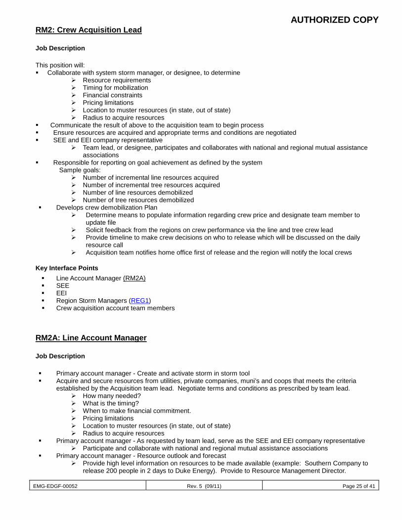
AUTHORIZED COPY
EMG-EDGF-00052 Rev. 5 (09/11) Page 25 of 41
RM2: Crew Acquisition Lead
Job Description This position will: Collaborate with system storm manager, or designee, to determine
Resource requirements Timing for mobilization Financial constraints Pricing limitations Location to muster resources (in state, out of state) Radius to acquire resources
Communicate the result of above to the acquisition team to begin process Ensure resources are acquired and appropriate terms and conditions are negotiated SEE and EEI company representative
Team lead, or designee, participates and collaborates with national and regional mutual assistance associations
Responsible for reporting on goal achievement as defined by the system Sample goals:
Number of incremental line resources acquired Number of incremental tree resources acquired Number of line resources demobilized Number of tree resources demobilized
Develops crew demobilization Plan Determine means to populate information regarding crew price and designate team member to
update file Solicit feedback from the regions on crew performance via the line and tree crew lead Provide timeline to make crew decisions on who to release which will be discussed on the daily
resource call Acquisition team notifies home office first of release and the region will notify the local crews
Key Interface Points Line Account Manager (RM2A) SEE EEI Region Storm Managers (REG1) Crew acquisition account team members
RM2A: Line Account Manager
Job Description Primary account manager - Create and activate storm in storm tool Acquire and secure resources from utilities, private companies, muni’s and coops that meets the criteria
established by the Acquisition team lead. Negotiate terms and conditions as prescribed by team lead. How many needed? What is the timing? When to make financial commitment. Pricing limitations Location to muster resources (in state, out of state) Radius to acquire resources
Primary account manager - As requested by team lead, serve as the SEE and EEI company representative Participate and collaborate with national and regional mutual assistance associations
Primary account manager - Resource outlook and forecast Provide high level information on resources to be made available (example: Southern Company to
release 200 people in 2 days to Duke Energy). Provide to Resource Management Director.
AUTHORIZED COPY
EMG-EDGF-00052 Rev. 5 (09/11) Page 26 of 41
Implement Crew Demobilization Plan Notify home office first of release as directed by Crew Mobilization team leads
Major issue resolution Handle unique issues as requested by the crew mobilization team leads or the resource management
director (examples: request for crews to sleep on cots, etc)
Key Interface Points Crew Acquisition Team Lead (RM2) Crew Mobilization Team Lead (RM3 & RM4)
Methods of performing job duties Conference Calls with SEE and EEI Participating in system storm calls Face to face, voice and email communications with team leads, external and internal resources/employees
Measures of success Crews acquired compared to goal No safety related incidents
Checklist of Actions
Before Major Storm Setup storm in Storm Resource Tracking Tool Determine schedule for crew acquisition support team and communicate Access to phone bank, printer, fax machine, and scanner
During Major Storm
Utilize storm mailboxes for all email communication Maintain key contact information (Contractors, SEE, EEI, etc.) Ensure adequate team resources are on hand and available for upcoming shifts Ensure daily deadlines/goals are met in regards to crew acquisition Ensure contracts and work releases are secured for each contractor Ensure compliance with SEE and EEI agreements
After Major Storm
To be included in a future revision of this document Tools and Information Needed Storm Resource Link (the web based crew tracking tool) Contracts and Work Releases for Contractors SEE and EEI agreements Training Requirements Knowledge of SEE and EEI agreements and process Knowledge of System Storm Resource Tool Knowledge of Contracts and Work Releases Knowledge of Crew Mobilization function
AUTHORIZED COPY
EMG-EDGF-00052 Rev. 5 (09/11) Page 27 of 41
RM2B: Tree Account Manager
Job Description Primary account manager - Create and activate storm in storm tool Acquire and secure resources from utilities, private companies, muni’s and coops that meets the criteria
established by the Acquisition team lead. Negotiate terms and conditions as prescribed by team lead. How many needed? What is the timing? When to make financial commitment. Pricing limitations Location to muster resources (in state, out of state) Radius to acquire resources
Primary account manager - As requested by team lead, serve as the SEE and EEI company representative Participate and collaborate with national and regional mutual assistance associations
Primary account manager - Resource outlook and forecast Provide high level information on resources to be made available (example: Southern Company to
release 200 people in 2 days to Duke Energy). Provide to Resource Management Director. Implement Crew Demobilization Plan
Notify home office first of release as directed by Crew Mobilization team leads Major issue resolution
Handle unique issues as requested by the crew mobilization team leads or the resource management director (examples: request for crews to sleep on cots, etc)
Key Interface Points Crew Acquisition Team Lead (RM2) Crew Mobilization Team Lead (RM3 & RM4)
Methods of performing job duties Conference Calls with SEE and EEI Participating in system storm calls Face to face, voice and email communications with team leads, external and internal resources/employees Measures of success Crews acquired compared to goal No safety related incidents
Checklist of Actions
Before Major Storm Setup storm in Storm Resource Tracking Tool Determine schedule for crew acquisition support team and communicate Access to phone bank, printer, fax machine, and scanner
During Major Storm
Utilize storm mailboxes for all email communication Maintain key contact information (Contractors, SEE, EEI, etc.) Ensure adequate team resources are on hand and available for upcoming shifts Ensure daily deadlines/goals are met in regards to crew acquisition Ensure contracts and work releases are secured for each contractor Ensure compliance with SEE and EEI agreements
After Major Storm
To be included in a future revision of this document Tools and Information Needed
Storm Resource Link (the web based crew tracking tool) Contracts and Work Releases for Contractors SEE and EEI agreements
AUTHORIZED COPY
EMG-EDGF-00052 Rev. 5 (09/11) Page 28 of 41
Training Requirements Knowledge of SEE and EEI agreements and process Knowledge of System Storm Resource Tool Knowledge of Contracts and Work Releases Knowledge of Crew Mobilization function
RM2A1: Support (Line) Job Description This position will: Assign crews to the regions based on direction from their lead Be responsible for meeting report and tool update deadlines during the course of the day (refer to crew timeline Handle incoming questions from the region storm room and handle, or route, accordingly Track internal tree resources moved to another area Run reports at designated times and provide to the lead Maintain back up information in case tool becomes inoperable at some point in the process
Maintain daily log book -Print crew lists and information twice per day and insert into tracking book to assist in reconciliation
Crew communication Team Responsible for manual GPS on tree crews Ensure the calls are being made to incoming crews, and that the tool is being updated with the latest ETA’s Track status of movement Once on system, initiate a daily call to ensure there are no issues Crew communication Provide directions to their show up site Provide regional contact information when appropriate Request rosters Ensure rosters are received from each crew Load information into a centralized page Ensure crew ID is included on the roster
Ensure smooth transition from system to regions for incoming crews If mustering site is used, after arriving there, turn them over to the region for future communication If mustering site not used, turn the crew over to the receiving region within 2-3 hours of arrival To facilitate the transition, the system will call the crew and notify them that the region will now take over
communication. Give the crew the region phone number and contact name but have the region initiate the call.
** Need a Spanish speaking person on the team
Checklist of Actions
Before Major Storm Refresher/Dry run of Storm Resource Tool Access to phone bank, printer, fax machine, and scanner
During Major Storm
Utilize storm mailboxes for all email communication Ensure timely and accurate input of resources acquired into Storm Tool Communication with Resource Mobilization team when new teams are mobilized
AUTHORIZED COPY
EMG-EDGF-00052 Rev. 5 (09/11) Page 29 of 41
RM2B1: Support (Tree) Job Description This position will: Assign crews to the regions based on direction from their lead Be responsible for meeting report and tool update deadlines during the course of the day (refer to crew timeline Handle incoming questions from the region storm room and handle, or route, accordingly Track internal tree resources moved to another area Run reports at designated times and provide to the lead Maintain back up information in case tool becomes inoperable at some point in the process
Maintain daily log book -Print crew lists and information twice per day and insert into tracking book to assist in reconciliation
Crew communication Team Responsible for manual GPS on tree crews Ensure the calls are being made to incoming crews, and that the tool is being updated with the latest ETA’s Track status of movement Once on system, initiate a daily call to ensure there are no issues Crew communication Provide directions to their show up site Provide regional contact information when appropriate Request rosters Ensure rosters are received from each crew Load information into a centralized page Ensure crew ID is included on the roster
Ensure smooth transition from system to regions for incoming crews If mustering site is used, after arriving there, turn them over to the region for future communication If mustering site not used, turn the crew over to the receiving region within 2-3 hours of arrival To facilitate the transition, the system will call the crew and notify them that the region will now take over
communication. Give the crew the region phone number and contact name but have the region initiate the call.
** Need a Spanish speaking person on the team
Checklist of Actions
Before Major Storm Refresher/Dry run of Storm Resource Tool Access to phone bank, printer, fax machine, and scanner
During Major Storm
Utilize storm mailboxes for all email communication Ensure timely and accurate input of resources acquired into Storm Tool Communication with Resource Mobilization team when new teams are mobilized
AUTHORIZED COPY
EMG-EDGF-00052 Rev. 5 (09/11) Page 30 of 41
RM3: System Line Mobilization Coordinator Job Description This position will: Participate on the daily system call with regions Manage crew assignment to regions Be decision maker for which crews are assigned to which region
a) The lead will factor in, crew equipment and capability. In order to make these decisions, the lead will refer to the comments section in the tool where that crew
acquisition will use to identify specifics on crews and they will also list equipment being brought. The lead will also receive verbal feedback on the system call with the region resource managers on their
needs. The lead will oversee the tool input personnel to ensure this information is updated in the Tool and the
region is notified (will ensure the input personnel include such pertinent information as climbing vs non climbing tree personnel, special equipment, etc)
b) Break down crews into 10-15 person teams and assign in that manner to the regions Mobilization notifies crew leader of team ID number
Communicate special needs related to outside resources Example: if a crew insists on using a mobile kitchen, the lead would provide that info on the system call to the region and to S&L who will also be on the call.
Elevated issue resolution with the regions Serve as the single point of contact when unique conflicts and situations arise
Responsible for manual GPS on crews Ensure the calls are being made to incoming crews, and that the tool is being updated with the latest
ETA’s Once on system, initiate a daily call to ensure there are no issues
Responsible to ensure rosters are received Ensure rosters are acquired from incoming crews and populate a shared drive with that information
Ensure smooth transition from system to regions for incoming crews If mustering site is used, after arriving there, turn them over to the region for future communication If mustering site not used, turn the crew over to the receiving region within 2-3 hours of arrival
To facilitate the transition, the system will call the crew and notify them that the region will now take over communication. Give the crew the region phone number and contact name but have the region initiate the call.
Track internal line resources moved to another area Resource forecast – ensure a resource forecast is available to the regions to provide a picture of resources to
come through the upcoming week Developing a contingency plan if tool is inoperable or phone lines are down Ensuring the crew mobilization storm kit and pre storm checklists are prepared/completed as outlined Ensuring direction books are available to provide appropriate information to incoming crews Provide the needed system reports at designated times Primary Interfaces: Region Resource Coordinators Fleet services Staging and Logistics system liaison Materials management Crew acquisition account managers
Methods of performing job duties: Face to face leadership of team members Participating in storm calls Voice and email communications with external and internal resources/employees
Measures of success: No safety related incidents Crew ready to work. % (Compare how many resources you forecast to be on property ready to work, versus, how
many resources ultimately were available) Tool input complete by prescribed daily deadlines
AUTHORIZED COPY
EMG-EDGF-00052 Rev. 5 (09/11) Page 31 of 41
Documents/forms needed to perform functions: Resource Mobilization Daily Timeline (attachment A) Storm Resource Link (the web based crew tracking tool) Directions to staging sites
Primary support location where employee works from: System storm room
Training Requirements Working knowledge of Resource Link Tool
Reporting function Crew Mobilization function
Checklist of Actions
Before Major Storm Establish via IT , email account for both line and tree support Establish via IT, router/hub network connection for team laptop computers Determine schedule for support team and communicate Determine if special travel access/documentation is required (obtain appropriate paperwork) – for contract
crews Access to Fax machine/scanner Access to printer for rosters and reports Ensure crew mobilization storm kit and pre-storm checklists are prepared/completed as outlined 2 hour Resource Link Tool refresher/dry run (via Live Meeting), if the tool has not been used within 1
month
During Major Storm Utilize storm mailboxes for all email communication Maintain key contact information (fleet, materials, etc.) Ensure adequate team resources are on hand and available for upcoming shifts Timely reporting available for daily storm calls Communicate Crew Mobilization system team phone numbers and e-mail addresses to Regions and
Operating Centers. Ensure team has Region and Op Center storm team phone numbers and e-mail addresses Ensure daily deadlines/goals are met in regards to input and crews ready to work Create/update daily log for exchange of issues from day shift to night shift
RM3A: Line Mobilization Support Job Description This position will: Tool input and crew splits Assign crews to the regions based on direction from their lead Provides crew leader with team ID number Be responsible for meeting report and tool update deadlines during the course of the day (refer to crew timeline) Region support Handle incoming questions from the region storm room and handle, or route, accordingly Track internal tree resources moved to another area Run reports at designated times and provide to the lead Maintain back up information in case tool becomes inoperable at some point in the process
Maintain daily log book -Print crew lists and information twice per day and insert into tracking book to assist in reconciliation
AUTHORIZED COPY
EMG-EDGF-00052 Rev. 5 (09/11) Page 32 of 41
Crew communication Team Be responsible for manual GPS on tree crews
Ensure the calls are being made to incoming crews, and that the tool is being updated with the latest ETA’s Track status of movement Once on system, initiate a daily call to ensure there are no issues
Crew communication Provide directions to their show up site Provide regional contact information when appropriate Request rosters Ensure rosters are received from each crew Load information into a centralized page Ensure crew ID is included on the roster Ensure smooth transition from system to regions for incoming crews If mustering site is used, after arriving there, turn them over to the region for future communication If mustering site not used, turn the crew over to the receiving region within 2-3 hours of arrival To facilitate the transition, the system will call the crew and notify them that the region will now take over
communication. Give the crew the region phone number and contact name but have the region initiate the call.
** Need a Spanish speaking person on the team
Checklist of Actions
Before Major Storm Contact Team Lead for schedule Attend 2 hour Resource Link Tool refresher/dry run (via Live Meeting), if the tool has not been used within
1 month
During Major Storm Utilize storm mailboxes for all email communication Timely reporting available for daily storm calls Ensure daily deadlines/goals are met in regards to input and crews ready to work
RM4: System Tree Coordinator Job Description This position will: Participate on the daily system call with regions Manage crew assignment to regions Be decision maker for which crews are assigned to which region
a) The lead will factor in, crew equipment and capability. In order to make these decisions, the lead will refer to the comments section in the tool where that crew
acquisition will use to identify specifics on crews and they will also list equipment being brought. The lead will also receive verbal feedback on the system call with the region resource managers on their
needs. The lead will oversee the tool input personnel to ensure this information is updated in the Tool and the
region is notified (will ensure the input personnel include such pertinent information as climbing vs non climbing tree personnel, special equipment, etc)
b) Break down crews into 10-15 person teams and assign in that manner to the regions Mobilization notifies crew leader of team ID number
Communicate special needs related to outside resources Example: if a crew insists on using a mobile kitchen, the lead would provide that info on the system call to the region and to S&L who will also be on the call.
Elevated issue resolution with the regions Serve as the single point of contact when unique conflicts and situations arise
AUTHORIZED COPY
EMG-EDGF-00052 Rev. 5 (09/11) Page 33 of 41
Responsible for manual GPS on crews Ensure the calls are being made to incoming crews, and that the tool is being updated with the latest
ETA’s Once on system, initiate a daily call to ensure there are no issues
Responsible to ensure rosters are received Ensure rosters are acquired from incoming crews and populate a shared drive with that information
Ensure smooth transition from system to regions for incoming crews If mustering site is used, after arriving there, turn them over to the region for future communication If mustering site not used, turn the crew over to the receiving region within 2-3 hours of arrival
To facilitate the transition, the system will call the crew and notify them that the region will now take over communication. Give the crew the region phone number and contact name but have the region initiate the call.
Track internal line resources moved to another area Resource forecast – ensure a resource forecast is available to the regions to provide a picture of resources to
come through the upcoming week Developing a contingency plan if tool is inoperable or phone lines are down Ensuring the crew mobilization storm kit and pre storm checklists are prepared/completed as outlined Ensuring direction books are available to provide appropriate information to incoming crews Provide the needed system reports at designated times Primary Interfaces: Region Resource Coordinators Fleet services Staging and Logistics system liaison Materials management Crew acquisition account managers
Methods of performing job duties: Face to face leadership of team members Participating in storm calls Voice and email communications with external and internal resources/employees
Measures of success: No safety related incidents Crew ready to work. % (Compare how many resources you forecast to be on property ready to work, versus, how
many resources ultimately were available) Tool input complete by prescribed daily deadlines Documents/forms needed to perform functions: Resource Mobilization Daily Timeline (attachment A) Storm Resource Link (the web based crew tracking tool) Directions to staging sites
Primary support location where employee works from: System storm room
Training Requirements Working knowledge of Resource Link Tool
Reporting function Crew Mobilization function
Checklist of Actions
Before Major Storm Establish via IT , email account for both line and tree support Establish via IT, router/hub network connection for team laptop computers Determine schedule for support team and communicate Determine if special travel access/documentation is required (obtain appropriate paperwork) – for contract
crews
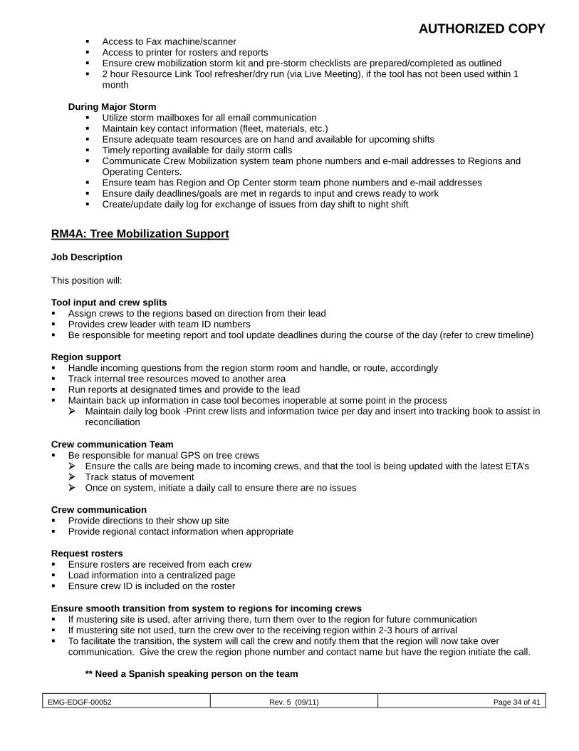
AUTHORIZED COPY
EMG-EDGF-00052 Rev. 5 (09/11) Page 34 of 41
Access to Fax machine/scanner Access to printer for rosters and reports Ensure crew mobilization storm kit and pre-storm checklists are prepared/completed as outlined 2 hour Resource Link Tool refresher/dry run (via Live Meeting), if the tool has not been used within 1
month
During Major Storm Utilize storm mailboxes for all email communication Maintain key contact information (fleet, materials, etc.) Ensure adequate team resources are on hand and available for upcoming shifts Timely reporting available for daily storm calls Communicate Crew Mobilization system team phone numbers and e-mail addresses to Regions and
Operating Centers. Ensure team has Region and Op Center storm team phone numbers and e-mail addresses Ensure daily deadlines/goals are met in regards to input and crews ready to work Create/update daily log for exchange of issues from day shift to night shift
RM4A: Tree Mobilization Support Job Description This position will: Tool input and crew splits Assign crews to the regions based on direction from their lead Provides crew leader with team ID numbers Be responsible for meeting report and tool update deadlines during the course of the day (refer to crew timeline) Region support Handle incoming questions from the region storm room and handle, or route, accordingly Track internal tree resources moved to another area Run reports at designated times and provide to the lead Maintain back up information in case tool becomes inoperable at some point in the process
Maintain daily log book -Print crew lists and information twice per day and insert into tracking book to assist in reconciliation
Crew communication Team Be responsible for manual GPS on tree crews
Ensure the calls are being made to incoming crews, and that the tool is being updated with the latest ETA’s Track status of movement Once on system, initiate a daily call to ensure there are no issues
Crew communication Provide directions to their show up site Provide regional contact information when appropriate Request rosters Ensure rosters are received from each crew Load information into a centralized page Ensure crew ID is included on the roster Ensure smooth transition from system to regions for incoming crews If mustering site is used, after arriving there, turn them over to the region for future communication If mustering site not used, turn the crew over to the receiving region within 2-3 hours of arrival To facilitate the transition, the system will call the crew and notify them that the region will now take over
communication. Give the crew the region phone number and contact name but have the region initiate the call.
** Need a Spanish speaking person on the team
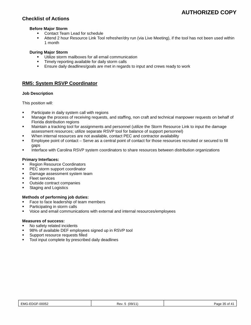
AUTHORIZED COPY
EMG-EDGF-00052 Rev. 5 (09/11) Page 35 of 41
Checklist of Actions
Before Major Storm Contact Team Lead for schedule Attend 2 hour Resource Link Tool refresher/dry run (via Live Meeting), if the tool has not been used within
1 month
During Major Storm Utilize storm mailboxes for all email communication Timely reporting available for daily storm calls Ensure daily deadlines/goals are met in regards to input and crews ready to work
RM5: System RSVP Coordinator Job Description This position will: Participate in daily system call with regions Manage the process of receiving requests, and staffing, non craft and technical manpower requests on behalf of
Florida distribution regions Maintain a tracking tool for assignments and personnel (utilize the Storm Resource Link to input the damage
assessment resources; utilize separate RSVP tool for balance of support personnel) When internal resources are not available, contact PEC and contractor availability Employee point of contact – Serve as a central point of contact for those resources recruited or secured to fill
gaps Interface with Carolina RSVP system coordinators to share resources between distribution organizations Primary Interfaces: Region Resource Coordinators PEC storm support coordinator Damage assessment system team Fleet services Outside contract companies Staging and Logistics Methods of performing job duties: Face to face leadership of team members Participating in storm calls Voice and email communications with external and internal resources/employees Measures of success: No safety related incidents 98% of available DEF employees signed up in RSVP tool Support resource requests filled Tool input complete by prescribed daily deadlines
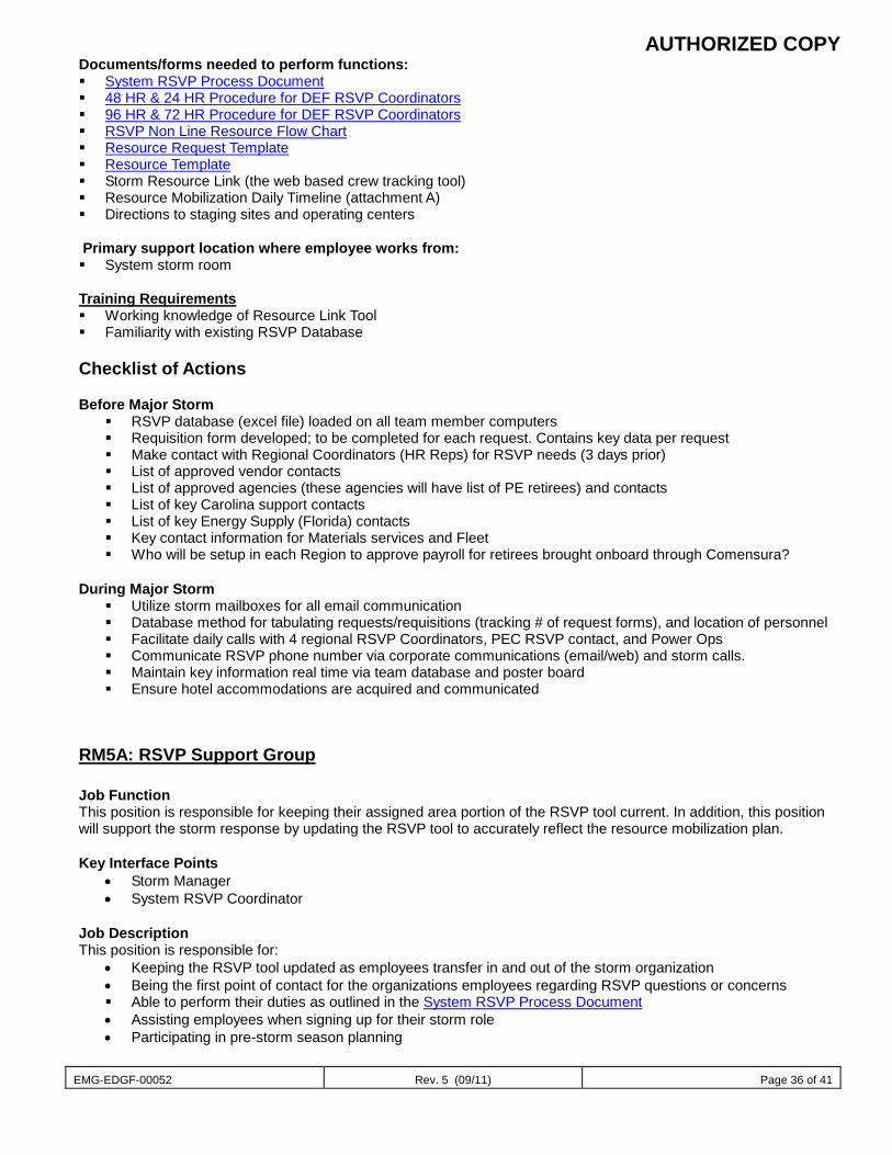
AUTHORIZED COPY
EMG-EDGF-00052 Rev. 5 (09/11) Page 36 of 41
Documents/forms needed to perform functions: System RSVP Process Document 48 HR & 24 HR Procedure for DEF RSVP Coordinators 96 HR & 72 HR Procedure for DEF RSVP Coordinators RSVP Non Line Resource Flow Chart Resource Request Template Resource Template Storm Resource Link (the web based crew tracking tool) Resource Mobilization Daily Timeline (attachment A) Directions to staging sites and operating centers
Primary support location where employee works from: System storm room
Training Requirements Working knowledge of Resource Link Tool Familiarity with existing RSVP Database Checklist of Actions Before Major Storm
RSVP database (excel file) loaded on all team member computers Requisition form developed; to be completed for each request. Contains key data per request Make contact with Regional Coordinators (HR Reps) for RSVP needs (3 days prior) List of approved vendor contacts List of approved agencies (these agencies will have list of PE retirees) and contacts List of key Carolina support contacts List of key Energy Supply (Florida) contacts Key contact information for Materials services and Fleet Who will be setup in each Region to approve payroll for retirees brought onboard through Comensura?
During Major Storm Utilize storm mailboxes for all email communication Database method for tabulating requests/requisitions (tracking # of request forms), and location of personnel Facilitate daily calls with 4 regional RSVP Coordinators, PEC RSVP contact, and Power Ops Communicate RSVP phone number via corporate communications (email/web) and storm calls. Maintain key information real time via team database and poster board Ensure hotel accommodations are acquired and communicated
RM5A: RSVP Support Group Job Function This position is responsible for keeping their assigned area portion of the RSVP tool current. In addition, this position will support the storm response by updating the RSVP tool to accurately reflect the resource mobilization plan. Key Interface Points
• Storm Manager • System RSVP Coordinator
Job Description This position is responsible for:
• Keeping the RSVP tool updated as employees transfer in and out of the storm organization • Being the first point of contact for the organizations employees regarding RSVP questions or concerns Able to perform their duties as outlined in the System RSVP Process Document • Assisting employees when signing up for their storm role • Participating in pre-storm season planning
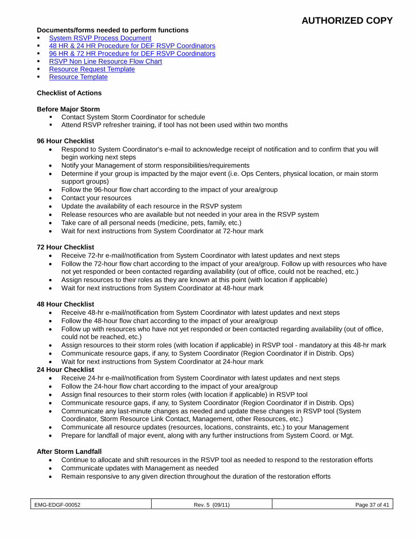
AUTHORIZED COPY
EMG-EDGF-00052 Rev. 5 (09/11) Page 37 of 41
Documents/forms needed to perform functions System RSVP Process Document 48 HR & 24 HR Procedure for DEF RSVP Coordinators 96 HR & 72 HR Procedure for DEF RSVP Coordinators RSVP Non Line Resource Flow Chart Resource Request Template Resource Template Checklist of Actions Before Major Storm
Contact System Storm Coordinator for schedule Attend RSVP refresher training, if tool has not been used within two months
96 Hour Checklist
• Respond to System Coordinator's e-mail to acknowledge receipt of notification and to confirm that you will begin working next steps
• Notify your Management of storm responsibilities/requirements • Determine if your group is impacted by the major event (i.e. Ops Centers, physical location, or main storm
support groups) • Follow the 96-hour flow chart according to the impact of your area/group • Contact your resources • Update the availability of each resource in the RSVP system • Release resources who are available but not needed in your area in the RSVP system • Take care of all personal needs (medicine, pets, family, etc.) • Wait for next instructions from System Coordinator at 72-hour mark
72 Hour Checklist
• Receive 72-hr e-mail/notification from System Coordinator with latest updates and next steps • Follow the 72-hour flow chart according to the impact of your area/group. Follow up with resources who have
not yet responded or been contacted regarding availability (out of office, could not be reached, etc.) • Assign resources to their roles as they are known at this point (with location if applicable) • Wait for next instructions from System Coordinator at 48-hour mark
48 Hour Checklist
• Receive 48-hr e-mail/notification from System Coordinator with latest updates and next steps • Follow the 48-hour flow chart according to the impact of your area/group • Follow up with resources who have not yet responded or been contacted regarding availability (out of office,
could not be reached, etc.) • Assign resources to their storm roles (with location if applicable) in RSVP tool - mandatory at this 48-hr mark • Communicate resource gaps, if any, to System Coordinator (Region Coordinator if in Distrib. Ops) • Wait for next instructions from System Coordinator at 24-hour mark
24 Hour Checklist • Receive 24-hr e-mail/notification from System Coordinator with latest updates and next steps • Follow the 24-hour flow chart according to the impact of your area/group • Assign final resources to their storm roles (with location if applicable) in RSVP tool • Communicate resource gaps, if any, to System Coordinator (Region Coordinator if in Distrib. Ops) • Communicate any last-minute changes as needed and update these changes in RSVP tool (System
Coordinator, Storm Resource Link Contact, Management, other Resources, etc.) • Communicate all resource updates (resources, locations, constraints, etc.) to your Management • Prepare for landfall of major event, along with any further instructions from System Coord. or Mgt.
After Storm Landfall
• Continue to allocate and shift resources in the RSVP tool as needed to respond to the restoration efforts • Communicate updates with Management as needed • Remain responsive to any given direction throughout the duration of the restoration efforts
AUTHORIZED COPY
EMG-EDGF-00052 Rev. 5 (09/11) Page 38 of 41
During Restoration Effort Utilize storm mailboxes for all email communication Timely reporting available for daily storm calls Ensure daily deadlines/goals are met in regards to input and crews ready to work
After Restoration Effort
• Ensure all employees are released from the current storm in the RSVP tool • Participate in any lessons learned exercises after each storm event • Forward lessons learned results to the System RSVP Coordinator
Systems Resource Link tool Resource Tracking tool RSVP database
RM 6: Regional Resource Coordinator
Job Function
The Regional Resource Coordinator is responsible for accepting, tracking, and assigning all internal and external contractor line and tree resources to the appropriate Operations Centers. These individuals serve as the regional lead for all of the Operations Center Resource Management Coordinators (OPS3). Their leadership is critical to the success of each of the respective Operations Centers within the Region. They provide accurate, detailed resource information to the Regional Storm team.
Job Description Utilize the Resource Tracking tool to organize and track the incoming crews Communicate with the Region Storm Coordinator to determine the appropriate distribution of incoming
resources Participate in all Resource Management and Region Storm conference calls and provide feedback to the
General Manager and Region Storm Coordinator regarding information covered Provide direction and support for and lead any necessary conference calls with the Operations Center
Resource Management Coordinators. Also supports the local Operations with the OPS3 position with RM6A role taking precedence.
Key Interface Points Operations Center Resource Management Coordinator (OPS3) Staging and Logistic Regional Coordinators (SL6) Regional Tactical Management Coordinator (REG4) System Line Coordinator (RM3) System Tree Coordinator (RM4)
Tools and Information Needed Resource Tracking tool Contact list for entire Region Storm organization chart
AUTHORIZED COPY
EMG-EDGF-00052 Rev. 5 (09/11) Page 39 of 41
Checklist of Actions 72 Hours Prior to a Storm
Review Resource Tracking tool Take care of personal needs (medicine, pets, family, etc.)
o Review personal safety tips. \\nt000070\shares70\Distribution Storm Plan\Resource Management-DEF\Region
Resource Coordinators\Hurricane Safety Tips Review System Storm Plan – Resource Management Section
o EMG-EDGF-00052 Communicate pre-storm information to Resource Management personnel and Regional Storm Team Activate the Operations Center Resource Management Coordinators Verify RM storm organization is fully staffed. Ensure RM personnel are fully trained to their storm roles.
o Attend 2 hour Resource Tracking tool refresher/dry run (via live meeting). Communicate with S&L to validate staging sites to be opened. Setup daily storm calls with Operating Center resource coordinators. Ensure updated contact list for Region Personnel/Storm Rooms and Resource Management. Ensure updated RM contact information is posted on the Storm Center web site. Ensure key interfaces have been identified with their contact information. Ensure assigned storm room is functional. Participate on RSM and System storm preparation conference calls Engage Mobilization Team on special needs.
o Tree Climbers and Back Lot Line personnel are needed in SCO. 48 Hours Prior to a Storm
Review Resource Tracking tool Communicate with Regional Storm team Communicate pre-storm information to Resource Management personnel Communicate with S&L to validate staging sites to be opened Decide when to send employees home to make personal preparations. Provide employee assistance information to employees. Engage Region and Operating Centers on the following resource needs:
o See Procedures \\nt000070\shares70\Distribution Storm Plan\Resource Management-DEF\Region Resource Coordinators
Rental vehicles Radios Satellite Phones Marsh Masters Boats.
24 Hours Prior to a Storm
Review Resource Tracking tool Facilitate the development of pre-storm resource allocation plan. Assign resources to Op. Centers by crew. Notify Op. Center RM Coordinators of their assigned crews. Communicate with Regional Storm team Communicate pre-storm information to Resource Management personnel Communicate with S&L to validate staging sites to be opened Ask employees to consider family needs and/or evacuations where necessary.
AUTHORIZED COPY
EMG-EDGF-00052 Rev. 5 (09/11) Page 40 of 41
During Major Storm
Attend Storm conference calls Ensure all RM personnel are charging their time correctly to storm numbers. Remind RM personnel to use Storm Communication Resources for all storm related activities. (i.e. Mailboxes,
storm phone numbers, etc.) Update Resource Tracking tool. Communicate with Operations Center Resource Management Coordinators Allocate internal and external contractor resources to the Operations Centers Assign the appropriate contractors to the areas in need Provide feedback to the Regional Storm team Remain engaged with the Regional Tactical Management Coordinator Participate in RSM and System storm restoration conference calls Facilitate RM storm conference calls. Identify post storm resources to meet System Storm Coordinator requirements based upon predictive model. Acquire post storm resources to meet system requirements. Update Storm Tool with post storm resources and internal resource mobilization. Facilitate the development of a resource re-allocation plan, as needed. Facilitate the development of a resource draw down plan. Participate in the development of a post storm plan to complete temporary repairs.
After Major Storm
Communicate transition of resources off system. Communicate to Regional Team on status storm demobilization and when everyone can return to normal
duties. Communicate status of local crews that were sent out of region to Regional Team. Communicate with Operations Center Resource Management Coordinators Update Resource Tracking tool. Prepare for sweep type work and additional resources needed. Prepare reports for General Manager on numbers of resources used and potential costs. Participate in Storm lessons learned. Ensure contract line and tree resources are identified and retained to support any post storm “clean up” plans. Ensure de-activation of RM storm room is completed. Ensure all rental vehicles, satellite phones, radios, etc. are returned. Sponsor a post storm RM lessons learned and forward to the Distribution System Storm Coordinator.
Training Requirements
Before Major Storm Participate in Resource Tracking tool training Complete understanding of Regional Storm Plan and roles and responsibilities Provide Operations Center Resource Management Coordinators the necessary training to perform their
storm duties Assemble Resource Management team within the Region/Operations Center Storm Plans Successful participation in Annual Storm Drill
Battlefield Promotion Success Factors Collaboration between Resource Management, Regional Storm team, and Operations Center Resource
Management Coordinators Reports showing best practices and successful movement of resources Follow Regional Vision Statement: “Everyone Matters”

AUTHORIZED COPY
EMG-EDGF-00052 Rev. 5 (09/11) Page 41 of 41
RM6A: Crew Tracking Team
Job Function
This group is responsible for supporting the Regional Resource Coordinators efforts to mobilize, track, deploy and release assigned resources in the region
Job Description Utilize the Resource Link tracking tool Engage with Regional RSVP Coordinator to ensure PE employee activation is current Assist the Regional Work Planning and Review team
AUTHORIZED COPY
EMG-EDGF-00053 Rev. 3 (07/12) Page 1 of 16
Document title
Performance Support Document number
EMG-EDGF-00053 Applies to: Energy Delivery – Florida Keywords: emergency; distribution system storm operational plan Mission Performance Support is responsible for the support, configuration, compilation, analysis, and reporting of accurate outage information during major storm restorations. This information is used to communicate with customers and government agencies, and to facilitate deployment of appropriate resources such as line crews.
Roles and Responsibilities Organization Chart PS1: Performance Support Coordinator PS2: Retired PS3: Performance Reporting PS4: Data and Resource Logistics
PS4A: IT Logistics Coordinator PS5: Outage Management System Support
PS5A: OMS IT Grid Management Support
Check Lists 96 Hour Preparation 72 Hour Preparation 48 Hour Preparation 24 Hour Preparation DURING MAJOR STORM RESTORATION
Sub-processes The Performance Support functional process includes the following sub-processes: Performance Reporting Outage Management System Threshold Management
The Performance Support team participates in the following sub-processes: Assess, Isolate and Restore ( Section EMG-EDGX-00051) Customer equipment damage disconnect (CEDD D1) and reconnect (RCR R1) orders
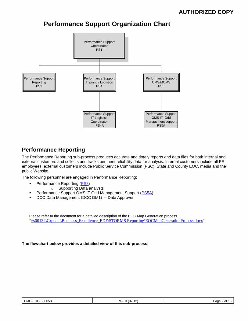
AUTHORIZED COPY
EMG-EDGF-00053 Rev. 3 (07/12) Page 2 of 16
Performance Support Organization Chart
Performance Support Coordinator
PS1
Performance Support Training / Logistics
PS4
Performance SupportOMS/MOMS
PS5
Performance Support Reporting
PS3
Performance SupportOMS IT Grid
Management supportPS5A
Performance Support IT Logistics Coordinator
PS4A
Performance Reporting The Performance Reporting sub-process produces accurate and timely reports and data files for both internal and external customers and collects and tracks pertinent reliability data for analysis. Internal customers include all PE employees; external customers include Public Service Commission (PSC), State and County EOC, media and the public Website. The following personnel are engaged in Performance Reporting:
Performance Reporting (PS3) o Supporting Data analysts
Performance Support OMS IT Grid Management Support (PS5A) DCC Data Management (DCC DM1) – Data Approver
Please refer to the document for a detailed description of the EOC Map Generation process. "\\s00134\Grpdata\Business_Excellence_EDF\STORMS Reporting\EOCMapGenerationProcess.docx"
The flowchart below provides a detailed view of this sub-process:
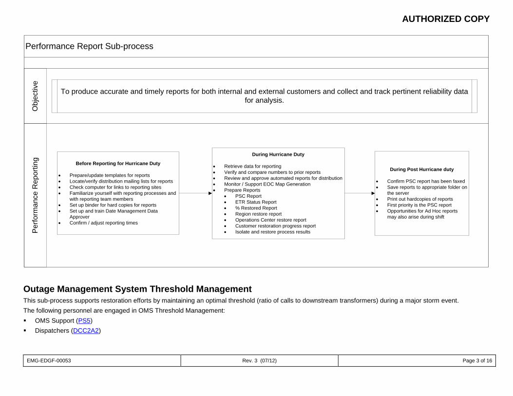
AUTHORIZED COPY
EMG-EDGF-00053 Rev. 3 (07/12) Page 3 of 16
Performance Report Sub-processP
erfo
rman
ce R
epor
ting
Obj
ectiv
e
Before Reporting for Hurricane Duty
• Prepare/update templates for reports• Locate/verify distribution mailing lists for reports• Check computer for links to reporting sites• Familiarize yourself with reporting processes and
with reporting team members• Set up binder for hard copies for reports• Set up and train Date Management Data
Approver• Confirm / adjust reporting times
During Hurricane Duty
• Retrieve data for reporting• Verify and compare numbers to prior reports• Review and approve automated reports for distribution• Monitor / Support EOC Map Generation• Prepare Reports
• PSC Report• ETR Status Report• % Restored Report• Region restore report• Operations Center restore report• Customer restoration progress report• Isolate and restore process results
During Post Hurricane duty
• Confirm PSC report has been faxed• Save reports to appropriate folder on
the server• Print out hardcopies of reports• First priority is the PSC report• Opportunities for Ad Hoc reports
may also arise during shift
To produce accurate and timely reports for both internal and external customers and collect and track pertinent reliability data for analysis.
Outage Management System Threshold Management This sub-process supports restoration efforts by maintaining an optimal threshold (ratio of calls to downstream transformers) during a major storm event. The following personnel are engaged in OMS Threshold Management: OMS Support (PS5) Dispatchers (DCC2A2)
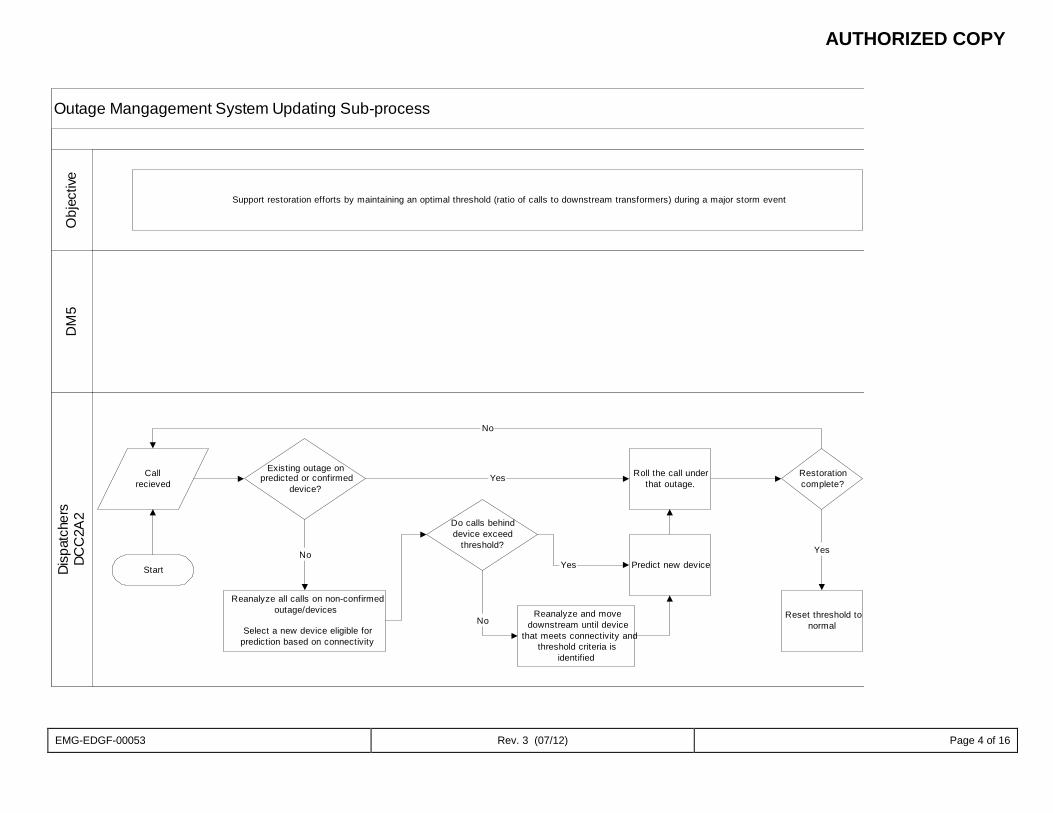
AUTHORIZED COPY
EMG-EDGF-00053 Rev. 3 (07/12) Page 4 of 16
Outage Mangagement System Updating Sub-process
DM
5Di
spat
cher
sDC
C2A
2O
bjec
tive
Support restoration efforts by maintaining an optimal threshold (ratio of calls to downstream transformers) during a major storm event
Start
Callrecieved
Existing outage onpredicted or confirmed
device?
Roll the call underthat outage.
Restorationcomplete?
Reset threshold tonormal
Predict new device
Reanalyze all calls on non-confirmedoutage/devices
Select a new device eligible forprediction based on connectivity
Reanalyze and movedownstream until device
that meets connectivity andthreshold criteria is
identified
Yes
No
Do calls behinddevice exceed
threshold?
No
Yes
Yes
No
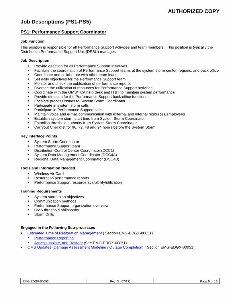
AUTHORIZED COPY
EMG-EDGF-00053 Rev. 3 (07/12) Page 5 of 16
Job Descriptions (PS1-PS5)
PS1: Performance Support Coordinator
Job Function This position is responsible for all Performance Support activities and team members. This position is typically the Distribution Performance Support Unit (DPSU) manager.
Job Description Provide direction for all Performance Support initiatives Facilitate the coordination of Performance Support teams at the system storm center, regions, and back office Coordinate and collaborate with other team leads Set daily objectives for the Performance Support team Monitor and check the publication of performance reports Oversee the utilization of resources for Performance Support activities Coordinate with the OMS/TCA help desk and IT&T to maintain system performance Provide direction for the Performance Support back office functions Escalate process issues to System Storm Coordinator Participate in system storm calls Participate in Performance Support calls Maintain voice and e-mail communication with external and internal resources/employees Establish system storm start time from System Storm Coordinator Establish threshold authority from System Storm Coordinator Carryout Checklist for 96, 72, 48 and 24 hours before the System Storm
Key Interface Points System Storm Coordinator Performance Support team Distribution Control Center Coordinator (DCC1) System Data Management Coordinator (DCC4A) Regional Data Management Coordinator (DCC4B)
Tools and Information Needed Wireless Air Card Restoration performance reports Performance Support resource availability/utilization
Training Requirements System storm plan objectives Communication methods Performance Support organization overview OMS threshold philosophy Storm Drills
Engaged in the Following Sub-processes Estimated Time of Restoration Management ( Section EMG-EDGX-00051) Performance Reporting Assess, Isolate, and Restore (See EMG-EDGX-00051)
OMS Updates (Damage Assessment Modeling / Outage Completion) ( Section EMG-EDGX-00051)
AUTHORIZED COPY
EMG-EDGF-00053 Rev. 3 (07/12) Page 6 of 16
PS3: Performance Reporting
Job Function These positions are responsible for preparing and posting restoration performance reports with a primary objective of preparing the restoration update for the FPSC and outage reporting to the State and County EOCs.
Job Description Obtain direction from Performance Support Coordinator Monitor and report the assess, isolate, and repair process outcome Provide ETR status update Prepare and post:
o FPSC report o Customers without power by county
Daily at set times by PS1:Performance Support Coordinator Format for Blackberry users
o Operations center restoration reports o Percent restore chart o Region restore report o Operations center restore chart o Customer restoration progress report o Connectivity Report o Wind tunnel Maps
Monitor and support the EOC Map Generation process that automatically prepares and distributes maps and data sets:
o State EOC – email distribution o County EOC – put the data on ftp folders
Participate in system storm calls Participate in Performance Support calls Maintain contact with Performance Support Coordinator Provide ad hoc restoration information as requested when not in conflict with FPSC reporting schedule
Key Interface Points Performance Support Coordinator (PS1) Corporate Communications Regional Data Management Coordinator (DCC4B) Performance Support OMS IT Grid Management support (PS5A) DCC Data Management (DCC DM1)
Tools and Information Needed Wireless Air Card Restoration performance report templates Report posting schedule Operations center Performance Support contact details Access to the corporate network Access to Oracle EOC and OMS databases Access to EOC Map Generation machine
Training Requirements Performance Support organization overview Understanding of Performance Support processes and sub-processes Storm Drills Proficient in MS Access, Excel, OMS Status, Restoration Trends, GeoMedia, Oracle, and batch scripts
Engaged in the Following Sub-processes Performance Reporting Assess, Isolate, and Restore (See EMG-EDGX-00051)
AUTHORIZED COPY
EMG-EDGF-00053 Rev. 3 (07/12) Page 7 of 16
PS4: Data and Resource Training / Logistics
Job Function This position is responsible for coordinating personnel, hardware, and software to support the Performance Support team as well as distribution system application training needs of the regional organization.
Job Description Obtain direction from Performance Support Coordinator Estimate gap in hardware, software, personnel resources Communicate demand for additional PC devices to OMS trouble call help desk support (PS5) Facilitate the move of hardware/software to identified locations Prepare list of potential additional I-Dispatch/Desktop MOMS operators based on region needs
o Collaborate with IT&T/DCC for additional, unassigned resources o Collaborate with IT&T / DCC DM1 to verify current OMS map is published to desktop MOMS
Create prioritized listing for deployment of additional resources Facilitate directions, lodging, transportation, arrival and departure of traveling Performance Support personnel Participate in Performance Support calls Update PS Storm - Share point site including contact information for all Performance Support resources Maintain contact with traveling Performance Support resources Prepare Helicopter fly over schedule and put on standby at PS1: Performance Support Coordinator direction
Key Interface Points Performance Support Coordinator (PS1) Performance Support team Staging and logistics (hotels) Fleet (rental cars) DCC, Data Management Team IT&T
Tools and Information Needed Wireless Air Card Available, off system resources to supplement op center Performance Support teams
Training Requirements Performance Support organization overview Storm Drills Communication methods
Engaged in the Following Sub-processes Performance Reporting
AUTHORIZED COPY
EMG-EDGF-00053 Rev. 3 (07/12) Page 8 of 16
PS4A: IT Logistics Coordinator
Job Function These positions are responsible for data collection, technical adjustments, training, and tracking of status of technical systems. This position is typically an IT Supervisor of the DTAs.
Job Description Provide systems technical support Facilitate the acquisition of additional PC equipment Participate in Performance Support storm calls Collaborate with key IT&T resources to start, run, and maintain storm only procedures and applications
Key Interface Points Data and Resource Logistics (PS4) DCC IT&T
Tools and Information Needed All technical tools and resources
Training Requirements Performance Support organization overview Storm drills Communication methods
Engaged in the Following Sub-processes Performance Reporting
AUTHORIZED COPY
EMG-EDGF-00053 Rev. 3 (07/12) Page 9 of 16
PS5: Outage Management System Support
Job Function This position is responsible for the performance of all restorations systems, and key technical personnel.
Job Description Obtain Performance Support objectives from the Performance Support Coordinator (PS1) Provide direction and oversight of OMS IT Grid Management Support (PS5A) Collaborate on roll-up logic adjustments Administer data collection for Performance Reporting (PS3) Advise and change roll-up logic when requested Monitor and advise on disposition of system performance Participate in system storm calls Participate in Performance Support calls Oversee refresher and update training program Supply training for I-Dispatch and Desktop MOMS systems (Train the Trainer) Elevate issues to Performance Support Coordinator Coordinate with key IT&T resources to start, run, and maintain storm only procedures and applications Coordinate with key CSC PSU Contacts for Turning off callbacks. Toggle restoration call-backs (Operation Center Level)
Key Interface Points Performance Support Coordinator DCC IT&T CSC PSU Contact
Tools and Information Needed Wireless Air Card Laptop Region expectation for additional I-Dispatch/Desktop MOMS PCs
Training Requirements Performance Support organization overview Storm scenarios workshop Communication methods
Engaged in the Following Sub-processes Performance Reporting
AUTHORIZED COPY
EMG-EDGF-00053 Rev. 3 (07/12) Page 10 of 16
PS5A: OMS IT Grid Management Support
Job Function These positions are responsible for data collection, technical adjustments, training, and tracking of status of technical systems. This position is typically an IT individual contributor with subject matter expertise in all restoration systems and processes.
Job Description Provide systems technical support Log system settings as they change before, during, and after storm Toggle restoration call-backs (System Level - CSS) Maintain restoration systems performance Collect raw data for restoration performance reporting Participate in Performance Support storm calls Collaborate with key IT&T resources to start, run, and maintain storm only procedures and applications
Restoration trends, county restoration summary Support EOC Map Generation
Key Interface Points OMS Support (PS5) DCC IT&T
Tools and Information Needed All technical tools and resources
Training Requirements Performance Support organization overview Storm drill Communication methods
Engaged in the Following Sub-processes Performance Reporting
AUTHORIZED COPY
EMG-EDGF-00053 Rev. 3 (07/12) Page 11 of 16
When we have storm drills OR real events, there are two types of calls held by the System Storm Coordinator:
1. Operations calls- Includes small group of operational leaders, typically Distribution Services Director and DPSU Manager. Checklist items are discussed and decisions are made
2. System calls - Includes large group of system leaders (operations, plus support services (Distribution Services Director and DPSU Manager). It is more of a report out call for senior leadership to hear that there aren’t any issues and to report high level activities
3. Both calls are generally limited to Distribution Services Director and DPSU Manager however, team members would be on if they are covering for another member
96 Hour Preparation (BEFORE MAJOR STORM)
Start participating on System Storm Calls. Contact OMS Vendor Intergraph.
Ensure that Performance Support Storm Organization Chart is up-to-date. Alert all Performance Support personnel that 96 hour checklists have begun for awareness.
AUTHORIZED COPY
EMG-EDGF-00053 Rev. 3 (07/12) Page 12 of 16
72 Hour Preparation (BEFORE MAJOR STORM)
Verify All 96 Hour Checklist Items Ensure that Performance Support Storm Organization Chart is up-to-date
Verify / Establish Names, Backup Personnel, and Schedules for each PS# position Notify IT and verify matching schedules for 24 hour support Notify DCC Data Manager (DM1) Hold all OMS map updates Hold all OMS and OMS related system upgrades with IT&T
Publish support Phone numbers Hold 1st PS Team meeting to engage needed roles and begin plans for future meetings
Work with PS4 to schedule deployment for MOMS/Imobile TC and OMS/I-dispatch machines
(Locations and Quantities) On Level 4 storm and above notify appropriate levels for engagement:
Distribution Services Director IT&T Director DCC Director
Track storm path and system storm center notifications to determine Performance Support OMS Storm
operational room location IT to ensure all I/Dispatcher (OMS) workstations are up to date (latest map, patches, etc) IT to ensure all existing Mobile TC (Desktop MOMS) workstations are up to date (latest map, patches,
etc) Identify workstations at local Op Centers which need to have MobileTC installed
Hold - Evaluate and (Authorize or Reject) PS4 to place Helicopter for Aerial Transformer Verification
on standby Touch base with the DM team to ensure Data Center (DCC training room) machines are pointed to OMS
production and ready for use Establish Points of Contact
o ITT overall POC (called Crisis Manager) along with backup (escalation to Crisis Director) and mobile numbers for both
o I-factor POC from ITT o CSC Point of Contact, discuss 21st Century Poller time threshold o Establish Regulatory Affairs POC for State reporting times o Establish Mgr-Public Policy & Constituency
Confirm the reporting times for all external reports with Mgr-Public Policy & Constituency Place established reporting times on Share point Storm Site. Confirm EOC databases and map generation processes are working properly Ensure DCC GIS Technician (DM team) has updated MapBoard maps to PDF. Engage DCC DM1 on approval process for reporting
Questions to Ask on 72 hour System Calls: • Will the DCC be centralized or decentralized? (DCC determined)
AUTHORIZED COPY
EMG-EDGF-00053 Rev. 3 (07/12) Page 13 of 16
48 Hour Preparation (BEFORE MAJOR STORM)
Verify ALL 96 Hour and 72 Hour Checklist Items Verify Deployment of OMS / I-dispatch hardware Create all needed templates for Day 1
All Reporting Templates
PSC Customer by county
Logistic Forms
Start to schedule conference calls (2 per day) with leads (CSC, DCC, System & Regional PS
Coordinators, Resource Deployment & OMS Help Desk, DPSU leads, Business Excellence POC, and IT Coordinator, Performance Support IT Grid (PS5a)
Set-up Performance Support OMS Storm operational room in coordination with System Storm
Coordinator Test Restoration Trends Report Coordinate with CSC PSU & IT&T Crisis Manager to reconcile the number of customers by county for
the Outage Mapping Application (I-Factor)
Hold - Evaluate Aerial Transformer Verification (Helicopter Fly-Over) standby status
Questions to Ask on 48 hour System Calls: • Will the DCC be centralized or decentralized? (DCC determined)
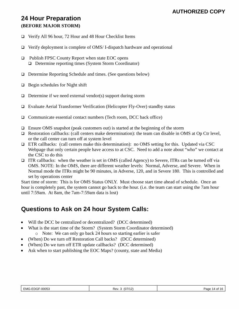
AUTHORIZED COPY
EMG-EDGF-00053 Rev. 3 (07/12) Page 14 of 16
24 Hour Preparation (BEFORE MAJOR STORM)
Verify All 96 hour, 72 Hour and 48 Hour Checklist Items Verify deployment is complete of OMS/ I-dispatch hardware and operational Publish FPSC County Report when state EOC opens
Determine reporting times (System Storm Coordinator)
Determine Reporting Schedule and times. (See questions below) Begin schedules for Night shift Determine if we need external vendor(s) support during storm Evaluate Aerial Transformer Verification (Helicopter Fly-Over) standby status
Communicate essential contact numbers (Tech room, DCC back office)
Ensure OMS snapshot (peak customers out) is started at the beginning of the storm Restoration callbacks: (call centers make determination): the team can disable in OMS at Op Ctr level,
or the call center can turn off at system level ETR callbacks: (call centers make this determination): no OMS setting for this. Updated via CSC
Webpage that only certain people have access to at CSC. Need to add a note about “who” we contact at the CSC to do this
ITR callbacks: when the weather is set in OMS (called Agency) to Severe, ITRs can be turned off via OMS. NOTE: In the OMS, there are different weather levels: Normal, Adverse, and Severe. When in Normal mode the ITRs might be 90 minutes, in Adverse, 120, and in Severe 180. This is controlled and set by operations center
Start time of storm: This is for OMS Status ONLY. Must choose start time ahead of schedule. Once an hour is completely past, the system cannot go back to the hour. (i.e. the team can start using the 7am hour until 7:59am. At 8am, the 7am-7:59am data is lost)
Questions to Ask on 24 hour System Calls: • Will the DCC be centralized or decentralized? (DCC determined) • What is the start time of the Storm? (System Storm Coordinator determined)
o Note: We can only go back 24 hours so starting earlier is safer • (When) Do we turn off Restoration Call backs? (DCC determined) • (When) Do we turn off ETR update callbacks? (DCC determined) • Ask when to start publishing the EOC Maps? (county, state and Media)
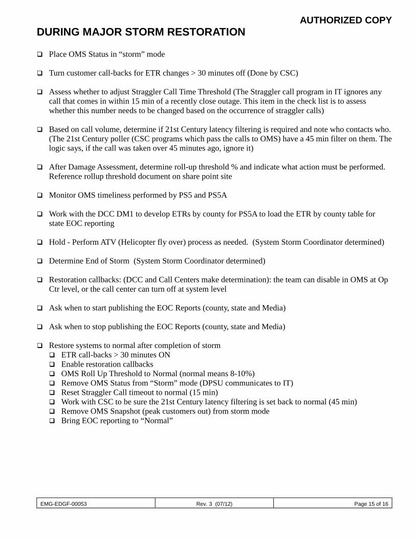
AUTHORIZED COPY
EMG-EDGF-00053 Rev. 3 (07/12) Page 15 of 16
DURING MAJOR STORM RESTORATION Place OMS Status in “storm” mode Turn customer call-backs for ETR changes > 30 minutes off (Done by CSC)
Assess whether to adjust Straggler Call Time Threshold (The Straggler call program in IT ignores any
call that comes in within 15 min of a recently close outage. This item in the check list is to assess whether this number needs to be changed based on the occurrence of straggler calls)
Based on call volume, determine if 21st Century latency filtering is required and note who contacts who.
(The 21st Century poller (CSC programs which pass the calls to OMS) have a 45 min filter on them. The logic says, if the call was taken over 45 minutes ago, ignore it)
After Damage Assessment, determine roll-up threshold % and indicate what action must be performed.
Reference rollup threshold document on share point site Monitor OMS timeliness performed by PS5 and PS5A
Work with the DCC DM1 to develop ETRs by county for PS5A to load the ETR by county table for
state EOC reporting
Hold - Perform ATV (Helicopter fly over) process as needed. (System Storm Coordinator determined)
Determine End of Storm (System Storm Coordinator determined)
Restoration callbacks: (DCC and Call Centers make determination): the team can disable in OMS at Op Ctr level, or the call center can turn off at system level
Ask when to start publishing the EOC Reports (county, state and Media)
Ask when to stop publishing the EOC Reports (county, state and Media)
Restore systems to normal after completion of storm
ETR call-backs > 30 minutes ON Enable restoration callbacks OMS Roll Up Threshold to Normal (normal means 8-10%) Remove OMS Status from “Storm” mode (DPSU communicates to IT) Reset Straggler Call timeout to normal (15 min) Work with CSC to be sure the 21st Century latency filtering is set back to normal (45 min) Remove OMS Snapshot (peak customers out) from storm mode Bring EOC reporting to “Normal”

AUTHORIZED COPY
EMG-EDGF-00053 Rev. 3 (07/12) Page 16 of 16
Systems I-Dispatch GeoMedia GIS Desktop Mobile Outage Management System Outage Management System Summary County Summary Restoration Trends Event List reports
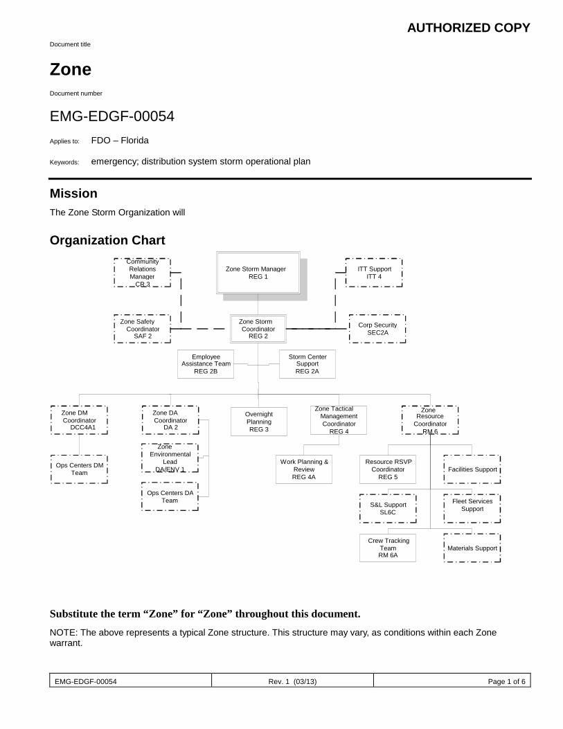
AUTHORIZED COPY
EMG-EDGF-00054 Rev. 1 (03/13) Page 1 of 6
Document title
Zone Document number
EMG-EDGF-00054 Applies to: FDO – Florida Keywords: emergency; distribution system storm operational plan
Mission The Zone Storm Organization will
Organization Chart
Substitute the term “Zone” for “Zone” throughout this document. NOTE: The above represents a typical Zone structure. This structure may vary, as conditions within each Zone warrant.
Zone Storm Manager REG 1
Zone Storm Coordinator
REG 2
Community Relations Manager
CR 3
Zone Safety Coordinator
SAF 2
ITT Support ITT 4
Corp Security SEC2A
Zone DM Coordinator
DCC4A1 Zone DA Coordinator
DA 2 Overnight Planning REG 3
Zone Tactical Management Coordinator
REG 4
Zone Resource
Coordinator RM 6
Employee Assistance Team
REG 2B Storm Center
Support REG 2A
Ops Centers DA Team
Resource RSVP Coordinator
REG 5 Facilities Support
S&L Support SL6C
Fleet Services Support
Crew Tracking Team RM 6A
Materials Support
Work Planning & Review REG 4A
Ops Centers DM Team
Zone Environmental
Lead DA/ENV 1
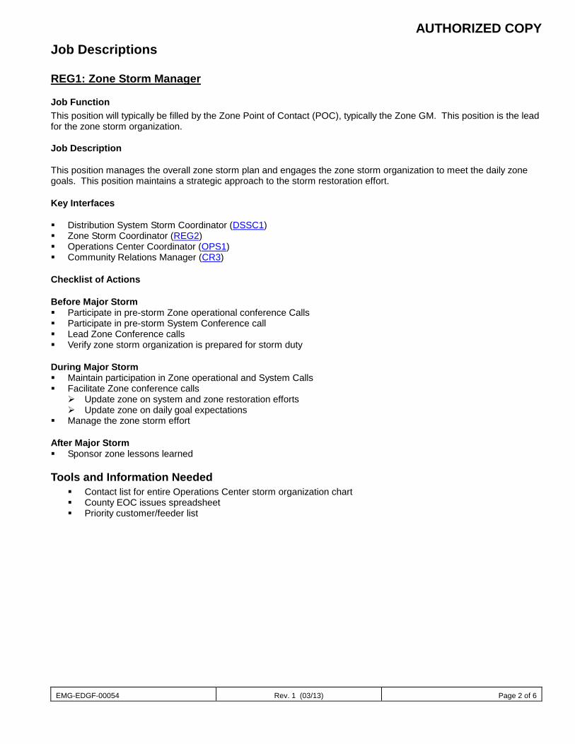
AUTHORIZED COPY
EMG-EDGF-00054 Rev. 1 (03/13) Page 2 of 6
Job Descriptions REG1: Zone Storm Manager
Job Function This position will typically be filled by the Zone Point of Contact (POC), typically the Zone GM. This position is the lead for the zone storm organization. Job Description This position manages the overall zone storm plan and engages the zone storm organization to meet the daily zone goals. This position maintains a strategic approach to the storm restoration effort. Key Interfaces Distribution System Storm Coordinator (DSSC1) Zone Storm Coordinator (REG2) Operations Center Coordinator (OPS1) Community Relations Manager (CR3) Checklist of Actions Before Major Storm Participate in pre-storm Zone operational conference Calls Participate in pre-storm System Conference call Lead Zone Conference calls Verify zone storm organization is prepared for storm duty
During Major Storm Maintain participation in Zone operational and System Calls Facilitate Zone conference calls
Update zone on system and zone restoration efforts Update zone on daily goal expectations
Manage the zone storm effort After Major Storm Sponsor zone lessons learned
Tools and Information Needed Contact list for entire Operations Center storm organization chart County EOC issues spreadsheet Priority customer/feeder list
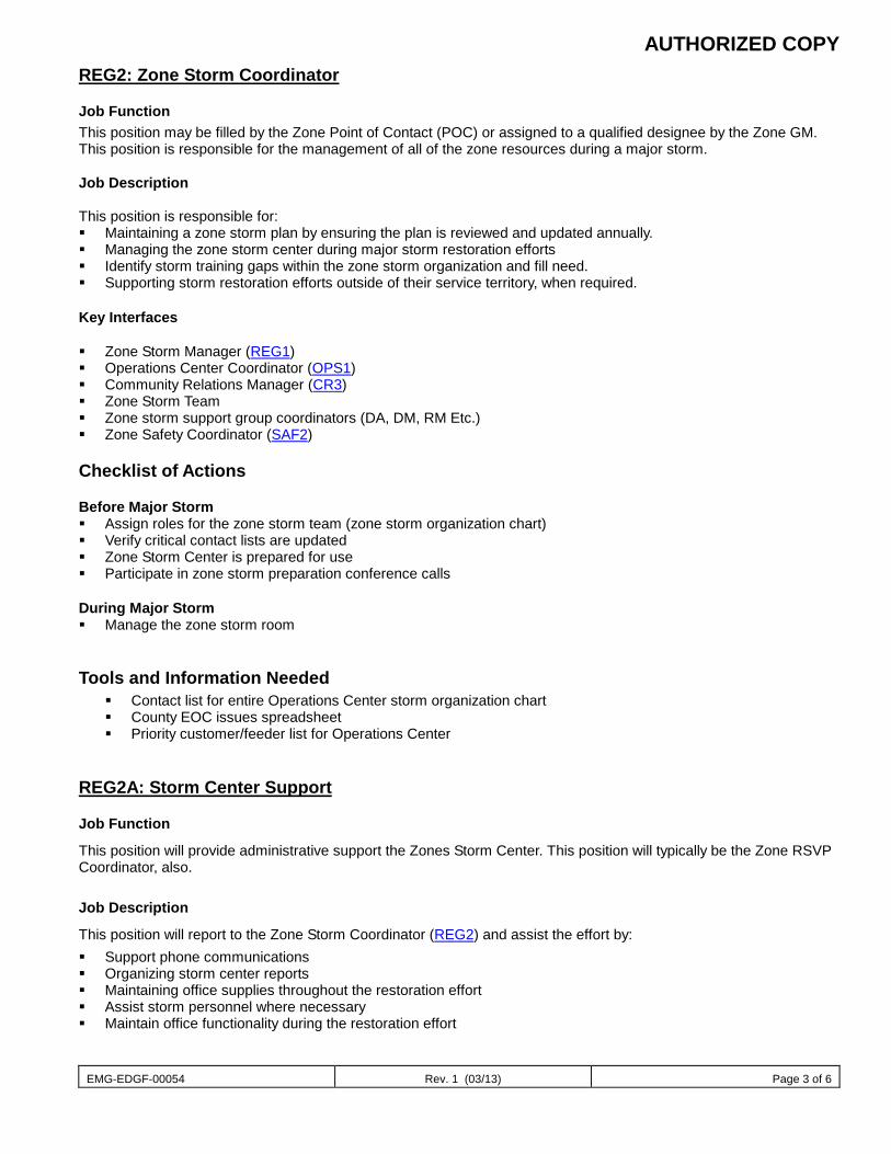
AUTHORIZED COPY
EMG-EDGF-00054 Rev. 1 (03/13) Page 3 of 6
REG2: Zone Storm Coordinator
Job Function This position may be filled by the Zone Point of Contact (POC) or assigned to a qualified designee by the Zone GM. This position is responsible for the management of all of the zone resources during a major storm. Job Description This position is responsible for: Maintaining a zone storm plan by ensuring the plan is reviewed and updated annually. Managing the zone storm center during major storm restoration efforts Identify storm training gaps within the zone storm organization and fill need. Supporting storm restoration efforts outside of their service territory, when required.
Key Interfaces Zone Storm Manager (REG1) Operations Center Coordinator (OPS1) Community Relations Manager (CR3) Zone Storm Team Zone storm support group coordinators (DA, DM, RM Etc.) Zone Safety Coordinator (SAF2) Checklist of Actions Before Major Storm Assign roles for the zone storm team (zone storm organization chart) Verify critical contact lists are updated Zone Storm Center is prepared for use Participate in zone storm preparation conference calls During Major Storm Manage the zone storm room
Tools and Information Needed Contact list for entire Operations Center storm organization chart County EOC issues spreadsheet Priority customer/feeder list for Operations Center
REG2A: Storm Center Support
Job Function
This position will provide administrative support the Zones Storm Center. This position will typically be the Zone RSVP Coordinator, also.
Job Description
This position will report to the Zone Storm Coordinator (REG2) and assist the effort by: Support phone communications Organizing storm center reports Maintaining office supplies throughout the restoration effort Assist storm personnel where necessary Maintain office functionality during the restoration effort
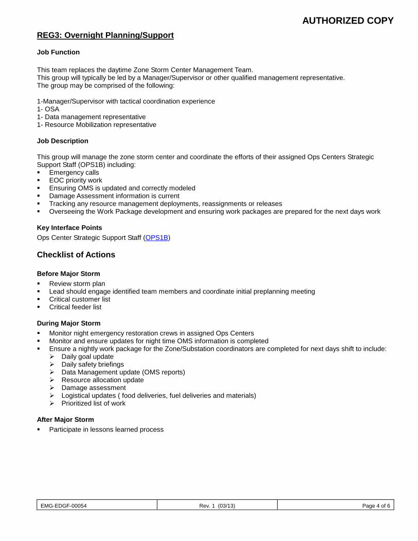
AUTHORIZED COPY
EMG-EDGF-00054 Rev. 1 (03/13) Page 4 of 6
REG3: Overnight Planning/Support
Job Function This team replaces the daytime Zone Storm Center Management Team. This group will typically be led by a Manager/Supervisor or other qualified management representative. The group may be comprised of the following: 1-Manager/Supervisor with tactical coordination experience 1- OSA 1- Data management representative 1- Resource Mobilization representative
Job Description This group will manage the zone storm center and coordinate the efforts of their assigned Ops Centers Strategic Support Staff (OPS1B) including: Emergency calls EOC priority work Ensuring OMS is updated and correctly modeled Damage Assessment information is current Tracking any resource management deployments, reassignments or releases Overseeing the Work Package development and ensuring work packages are prepared for the next days work
Key Interface Points Ops Center Strategic Support Staff (OPS1B)
Checklist of Actions
Before Major Storm Review storm plan Lead should engage identified team members and coordinate initial preplanning meeting Critical customer list Critical feeder list
During Major Storm Monitor night emergency restoration crews in assigned Ops Centers Monitor and ensure updates for night time OMS information is completed Ensure a nightly work package for the Zone/Substation coordinators are completed for next days shift to include:
Daily goal update Daily safety briefings Data Management update (OMS reports) Resource allocation update Damage assessment Logistical updates ( food deliveries, fuel deliveries and materials) Prioritized list of work
After Major Storm Participate in lessons learned process
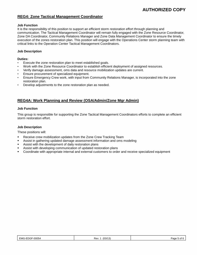
AUTHORIZED COPY
EMG-EDGF-00054 Rev. 1 (03/13) Page 5 of 6
REG4: Zone Tactical Management Coordinator Job Function It is the responsibility of this position to support an efficient storm restoration effort through planning and communication. The Tactical Management Coordinator will remain fully engaged with the Zone Resource Coordinator, Zone DA Coordinator, Community Relations Manager and Zone Data Management Coordinator to ensure the timely execution of the zones restoration plan. This position will engage with the Operations Center storm planning team with critical links to the Operation Center Tactical Management Coordinators. Job Description Duties: • Execute the zone restoration plan to meet established goals. • Work with the Zone Resource Coordinator to establish efficient deployment of assigned resources. • Verify damage assessment, oms data and resource mobilization updates are current. • Ensure procurement of specialized equipment. • Ensure Emergency Crew work, with input from Community Relations Manager, is incorporated into the zone
restoration plan. • Develop adjustments to the zone restoration plan as needed.
REG4A: Work Planning and Review (OSA/Admin/Zone Mgr Admin)
Job Function
This group is responsible for supporting the Zone Tactical Management Coordinators efforts to complete an efficient storm restoration effort.
Job Description These positions will: Receive crew mobilization updates from the Zone Crew Tracking Team Assist in gathering updated damage assessment information and oms modeling Assist with the development of daily restoration plans Assist with developing communication of updated restoration plans Coordinate with appropriate internal and external customers to order and receive specialized equipment
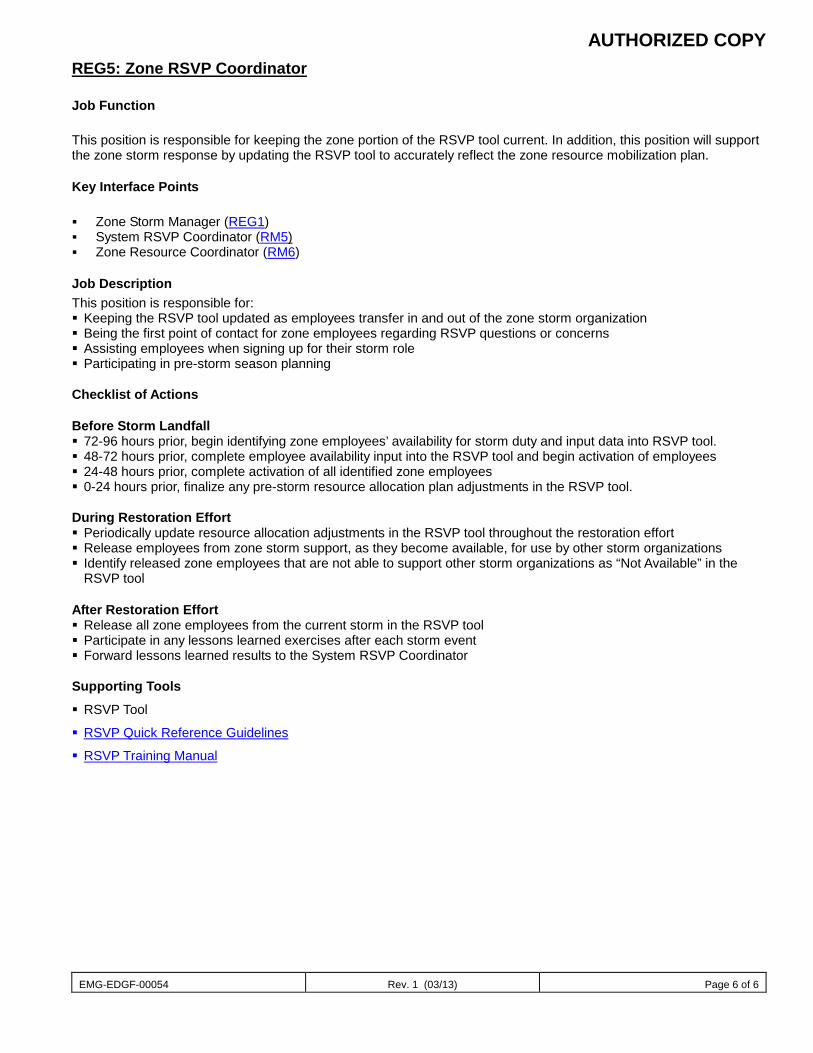
AUTHORIZED COPY
EMG-EDGF-00054 Rev. 1 (03/13) Page 6 of 6
REG5: Zone RSVP Coordinator
Job Function This position is responsible for keeping the zone portion of the RSVP tool current. In addition, this position will support the zone storm response by updating the RSVP tool to accurately reflect the zone resource mobilization plan.
Key Interface Points Zone Storm Manager (REG1) System RSVP Coordinator (RM5) Zone Resource Coordinator (RM6)
Job Description This position is responsible for: Keeping the RSVP tool updated as employees transfer in and out of the zone storm organization Being the first point of contact for zone employees regarding RSVP questions or concerns Assisting employees when signing up for their storm role Participating in pre-storm season planning Checklist of Actions Before Storm Landfall 72-96 hours prior, begin identifying zone employees’ availability for storm duty and input data into RSVP tool. 48-72 hours prior, complete employee availability input into the RSVP tool and begin activation of employees 24-48 hours prior, complete activation of all identified zone employees 0-24 hours prior, finalize any pre-storm resource allocation plan adjustments in the RSVP tool. During Restoration Effort Periodically update resource allocation adjustments in the RSVP tool throughout the restoration effort Release employees from zone storm support, as they become available, for use by other storm organizations Identify released zone employees that are not able to support other storm organizations as “Not Available” in the
RSVP tool After Restoration Effort Release all zone employees from the current storm in the RSVP tool Participate in any lessons learned exercises after each storm event Forward lessons learned results to the System RSVP Coordinator Supporting Tools
RSVP Tool
RSVP Quick Reference Guidelines
RSVP Training Manual
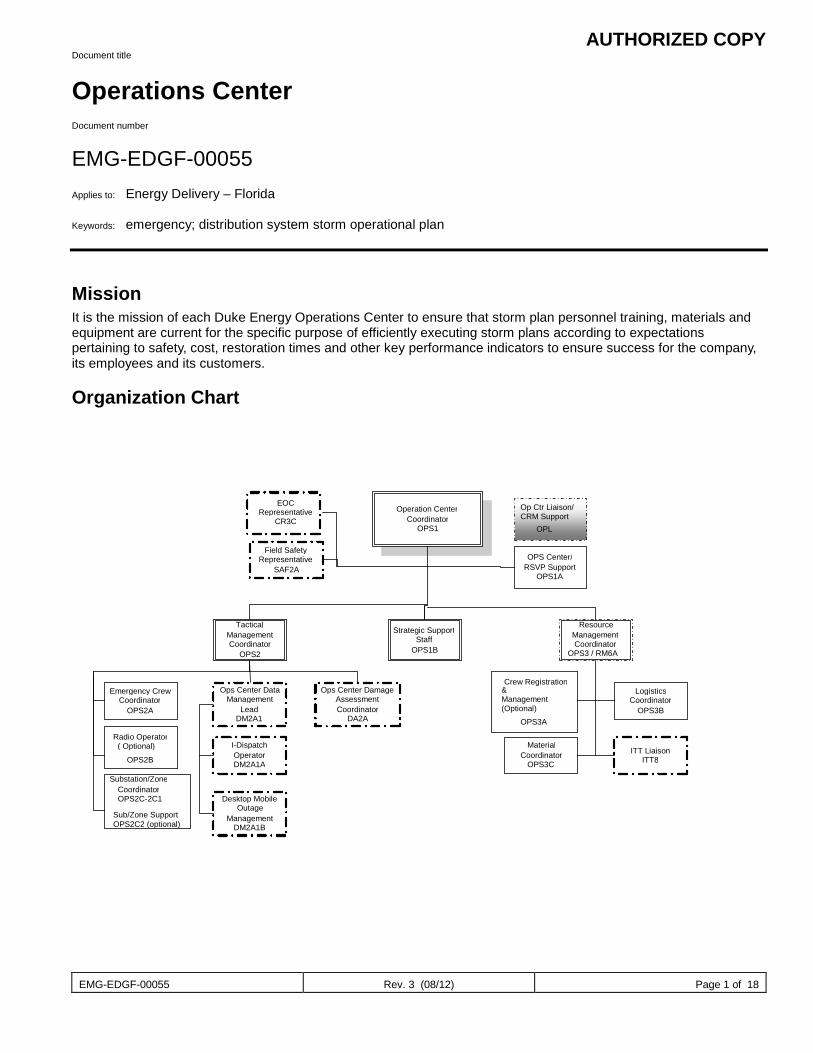
AUTHORIZED COPY
EMG-EDGF-00055 Rev. 3 (08/12) Page 1 of 18
Document title
Operations Center Document number
EMG-EDGF-00055 Applies to: Energy Delivery – Florida Keywords: emergency; distribution system storm operational plan
Mission It is the mission of each Duke Energy Operations Center to ensure that storm plan personnel training, materials and equipment are current for the specific purpose of efficiently executing storm plans according to expectations pertaining to safety, cost, restoration times and other key performance indicators to ensure success for the company, its employees and its customers.
Organization Chart
Operation Center Coordinator
OPS1
EOC Representative
CR3C
Field Safety Representative
SAF2A
Tactical Management Coordinator
OPS2
Strategic Support Staff
OPS1B
Resource Management Coordinator
OPS3 / RM6A
OPS Center/ RSVP Support
OPS1A
Emergency Crew Coordinator
OPS2A Ops Center Data
Management Lead
DM2A1
Ops Center Damage Assessment Coordinator
DA2A Radio Operator ( Optional)
OPS2B Substation/Zone
Coordinator OPS2C-2C1
I-Dispatch Operator DM2A1A
Desktop Mobile Outage
Management DM2A1B
Crew Registration
OPS3A
Logistics Coordinator
OPS3B
Material Coordinator
OPS3C ITT Liaison
ITT8
Sub/Zone Support OPS2C2 (optional)
& Management (Optional)
Op Ctr Liaison/ CRM Support
OPL
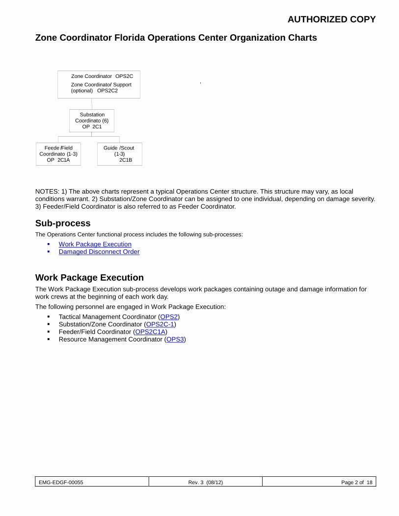
AUTHORIZED COPY
EMG-EDGF-00055 Rev. 3 (08/12) Page 2 of 18
Zone Coordinator Florida Operations Center Organization Charts
NOTES: 1) The above charts represent a typical Operations Center structure. This structure may vary, as local conditions warrant. 2) Substation/Zone Coordinator can be assigned to one individual, depending on damage severity. 3) Feeder/Field Coordinator is also referred to as Feeder Coordinator.
Sub-process The Operations Center functional process includes the following sub-processes:
Work Package Execution Damaged Disconnect Order
Work Package Execution The Work Package Execution sub-process develops work packages containing outage and damage information for work crews at the beginning of each work day. The following personnel are engaged in Work Package Execution:
Tactical Management Coordinator (OPS2) Substation/Zone Coordinator (OPS2C-1) Feeder/Field Coordinator (OPS2C1A) Resource Management Coordinator (OPS3)
Zone Coordinator ,
Substation Coordinato
( 6 ) OP
2 C 1
Feede
/ Field Coordinato
( 1 - 3 ) OP
2 C 1 A
Guide
/ Scout ( 1 - 3 )
2 C 1 B
,
Zone Coordinator Support (optional) OPS2C2
OPS2C
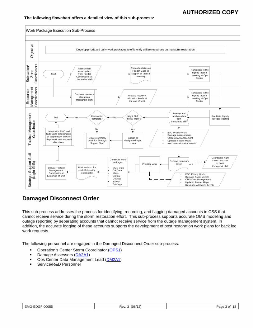
AUTHORIZED COPY
EMG-EDGF-00055 Rev. 3 (08/12) Page 3 of 18
The following flowchart offers a detailed view of this sub-process:
Damaged Disconnect Order This sub-process addresses the process for identifying, recording, and flagging damaged accounts in CSS that cannot receive service during the storm restoration effort. This sub-process supports accurate OMS modeling and outage reporting by separating accounts that cannot receive service from the outage management system. In addition, the accurate logging of these accounts supports the development of post restoration work plans for back log work requests. The following personnel are engaged in the Damaged Disconnect Order sub-process:
Operation’s Center Storm Coordinator (OPS1) Damage Assessors (DA2A1) Ops Center Data Management Lead (DM2A1) Service/R&D Personnel
Work Package Execution Sub-ProcessSu
bsta
tion/
Zone
Coo
rdin
ator
s
Res
ourc
eM
anag
emen
tC
oord
inat
ors
Tact
ical M
anag
emen
tCo
ordi
nato
rSt
rate
gic
Sup
port
Staf
f(N
ight
Shi
ft)O
bjec
tive
Develop prioritized daily work packages to efficiently utilize resources during storm restoration
Start
Record updates onFeeder Maps in
support of tacticalmeeting
Finalize resourceallocation levels at
the end of shift
Create summarydetail for Strategic
Support Staff
Participate in thenightly tacticalmeeting at Ops
Center
Receive lastwork updatefrom Feeder
Coordinators atthe end of shift
Participate in thenightly tacticalmeeting at Ops
Center
Facilitate NightlyTactical Meeting
True-up andanalyze data
fromcompleted shift
EOC Priority Work Damage Assessments OMS-Data Management Updated Feeder Maps Resource Allocation Levels
Night ShiftPriority Work?
Assign todesignated night
crews
Yes
Receive summarydetail
Coordinate nightcrews and true
up OMSthroughout shift
EOC Priority Work Damage Assessments OMS-Data Management Updated Feeder Maps Resource Allocation Levels
Construct workpackages
OMS Data DA Data Maps Critical
Devices Safety
Briefings
Prioritize workPrint and sort foreach Substation
Coordinator
Update TacticalManagementCoordinator at
beginning of shift
Meet with RMC andSubstation Coordinatorsat beginning of shift fordays work and resource
allocations
End Restorationcomplete?Yes
No
No
Continue resourceallocations
throughout shift
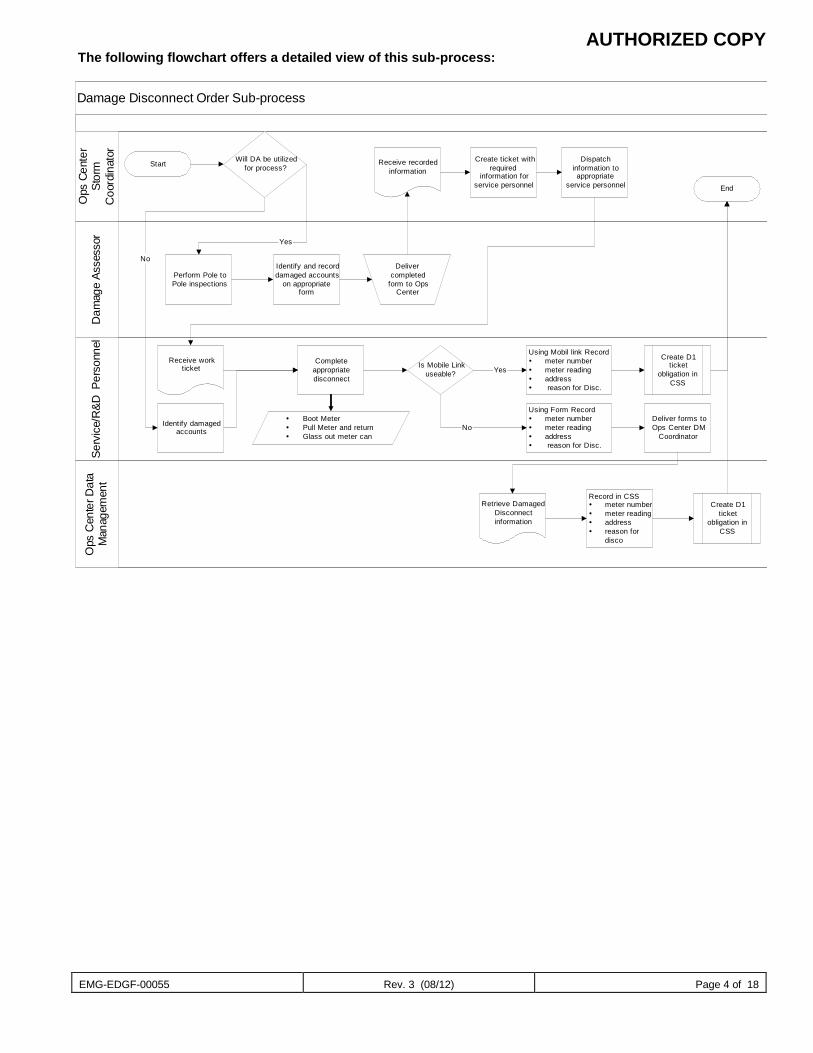
AUTHORIZED COPY
EMG-EDGF-00055 Rev. 3 (08/12) Page 4 of 18
The following flowchart offers a detailed view of this sub-process:
Damage Disconnect Order Sub-processO
ps C
ente
r Dat
aM
anag
emen
tD
amag
e As
sess
orSe
rvic
e/R
&D P
erso
nnel
Ops
Cen
ter
Stor
mC
oord
inat
or
StartWill DA be utilized
for process?
Identify and recorddamaged accounts
on appropriateform
Delivercompleted
form to OpsCenter
End
Receive recordedinformation
Dispatchinformation toappropriate
service personnel
Receive workticket
Create ticket withrequired
information forservice personnel
Completeappropriatedisconnect
Boot Meter Pull Meter and return Glass out meter can
Using Mobil link Record meter number meter reading address reason for Disc.
Yes
Identify damagedaccounts
Perform Pole toPole inspections
No
Is Mobile Linkuseable?
Create D1ticket
obligation inCSS
Yes
Using Form Record meter number meter reading address reason for Disc.
NoDeliver forms toOps Center DM
Coordinator
Retrieve DamagedDisconnectinformation
Record in CSS meter number meter reading address reason for
disco
Create D1ticket
obligation inCSS
AUTHORIZED COPY
EMG-EDGF-00055 Rev. 3 (08/12) Page 5 of 18
Job Descriptions (OPS1 – OPS3C)
OPS1: Operations Center Coordinator Job Function This position will typically be the Operations Point of Contact (supervisor) assigned to the center. This position provides the managerial oversight for the entire operation centers restoration effort. The OPS1 reports directly to the REG1 for the assigned region. This position should maintain a storm organizational and planning focus throughout the restoration effort. Current storm supporting forms, guidelines and tables for use by the Operations Centers can be found by utilizing the following link: DEF Supplemental Forms
Job Description This position is responsible for ensuring: The storm organizational chart is updated and that there are no personnel gaps prior to storm season (some roles
will be filled by supporting storm organizations or by PEC through the RSVP tool as needed) Storm personnel are fully trained The critical feeder lists are current EOC critical equipment and infrastructure lists are current The establishment of a work schedule that ensures a smooth transition between shifts - a 2 hour overlap is
recommended The Zone Storm Center receives timely updates as required The Operation Center storm restoration effort meets established goals. Utilize the following form for identifying critical feeders and their restoration priority: Feeder Prioritization form
Key Interface Points Zone Storm Manager (REG1) Tactical Management Coordinator (OPS2) EOC Representative (ER3B) Resource Management Coordinator (OPS3) DA Environmental Lead (DA/ENV1)
Before Major Storm Prior to storm landfall, the state of readiness for the Operation Center Storm Team is a critical component for a successful restoration effort. To assist the Operations Center Coordinator in verifying the level of readiness, the following checklist should be used: Operations Center Pre-Storm Checklist
During Major Storm Emphasize a safe restoration effort – Maintain personal safety as a value Ensure you can account for all assigned PE employees throughout the restoration effort Maintain a current list of all contract and other off-system crews working within your restoration activities Communicate restoration crew arrivals to the Region Storm Coordinator (REG2) Monitor OMS updates and ensure information accuracy Ensure prioritized feeder lists are being utilized Prioritize and respond to critical customer or emergency issues If nuclear sites are within your area of responsibilities, support the nuclear siren restoration plan Ensure oil spill events and other environmental issues are forwarded promptly to the Zone Environmental lead
(DA/ENV1)
AUTHORIZED COPY
EMG-EDGF-00055 Rev. 3 (08/12) Page 6 of 18
After Major Storm Ensure all personnel are accounted for Ensure all data from final sweeps are documented Sponsor an Operation Center Lessons Learned Operations Center Post-Storm Checklist
OPL: Ops Center Liaison/CRM Support
Job Function This position will provide the EOC rep and the CRM with a single, dedicated point of contact and interface with the local Op Ctr. This will allow dedicated and structured coordination between the CRM/EOC rep that will allow emerging issues with government officials to be addressed in the most effective and timely manner. This position will report directly to the CRM but will reside in the Op Center and coordinate directly with the Tactical Management Coordinator and/or the operations center POC. This position may be filled by the ops center personnel (OPS1A) /RSVP Support depending on the storm.
Job Description This position will report to the Community Relations Manager (CRM) and assist the efforts by: Monitor and manage all incoming calls from the CRM/EOC or other community focused entities Monitor and manage email accounts associated with the EOC and CRM Interface with local Tactical mgmt on restoration issues as brought forth by the EOC rep and the CRM Ensure CRM/EOC issues are assigned, completed and follow up communication with appropriate party is
accomplished in a timely and effective manner Update the Tactical mgmt coordinator and the DOM of emerging concerns, events, opportunities Assist storm personnel where necessary Maintain office functionality during the restoration effort This position also provides operating center support and back up as primary responsibilities allow: Support the local OPS1A as available
OPS1A: Ops Center/RSVP Support
Job Function This position will provide administrative support the Operations Storm Center and typically fills the role of Ops Center RSVP Coordinator.
Job Description This position will report to the Operation Center Coordinator (OPS1) and assist the effort by: Support phone communications Organizing storm center reports Maintaining office supplies throughout the restoration effort Assist storm personnel where necessary Maintain office functionality during the restoration effort This position as the Ops Center RSVP coordinator is responsible for: Keeping the RSVP tool updated as employees transfer in and out of the Ops Center storm organization Being the first point of contact for Ops Center employees regarding RSVP questions or concerns Assisting employees when signing up for their storm role Update Operations Center Storm Org Charts and install on Operations Storm web site Update Storm Plan Assignment form and install on Operations Center storm web site. Participating in pre-storm season planning
AUTHORIZED COPY
EMG-EDGF-00055 Rev. 3 (08/12) Page 7 of 18
RSVP Checklist of Actions
Before Storm Landfall 72-96 hours prior, begin identifying Ops Center employees’ availability for storm duty and input data into RSVP tool. 48-72 hours prior, complete employee availability input into the RSVP tool and begin activation of employees 24-48 hours prior, complete activation of all identified Ops Center employees 0-24 hours prior, finalize any pre-storm resource allocation plan adjustments in the RSVP tool.
During Restoration Effort Periodically update resource allocation adjustments in the RSVP tool throughout the restoration effort Release employees from Ops Center storm support, as they become available, for use by other storm organizations Identify released Ops Center employees that are not able to support other storm organizations as “Not Available” in
the RSVP tool
After Restoration Effort Release all Ops Center employees from the current storm in the RSVP tool Participate in any lessons learned exercises after each storm event Forward lessons learned results to the System RSVP Coordinator
Supporting Tools RSVP Tool
RSVP Quick Reference Guidelines
RSVP Training Manual
AUTHORIZED COPY
EMG-EDGF-00055 Rev. 3 (08/12) Page 8 of 18
Storm Plan Assignment form Storm Center Org Chart Medical Services Form
OPS1B: Strategic Support Staff (Night Shift)
Job Function This team replaces the daytime Operation Centers Storm Management Team and is an extremely critical function. This group will typically be led by one D.F.S. or other qualified management personnel with strong leadership. The group may be comprised of the following, but not required in all areas based on severity of the storm: 1-D.F.S 2- OSA’s 1- Engineer/Service Coordinator 1- Data management representative 1- Damage assessment representative
Job Description This group will take the day’s accomplishments and productivity and make packets for the next day’s work based on resource adjustments, new goals, and other emerging problems/events. This group will manage the operation centers night time storm restoration activities including: Emergency calls EOC priority work Ensuring OMS is updated and correctly modeled Damage Assessment information is current Tracking any resource management deployments, reassignments or releases Overseeing the Work Package development
Key Interface Points Ops Center Tactical Management Coordinator (OPS2) Ops Center Resource Management Coordinator (OPS3) Zone Night Support Team Material coordinator (OPS3C)
Checklist of Actions
Before Major Storm Review storm plan Lead should engage identified team members and coordinate initial preplanning meeting Critical customer list Critical feeder list
During Major Storm Manage night emergency restoration crews Monitor and update night time OMS information Update Ops Center employee update line ( if utilized) Develop a nightly work package for the Zone/Substation coordinators next days shift to include:
Daily goal update Daily safety briefings Data Management update (OMS reports) Resource allocation update Damage assessment Logistical updates ( food deliveries, fuel deliveries and materials) Prioritized list of work
AUTHORIZED COPY
EMG-EDGF-00055 Rev. 3 (08/12) Page 9 of 18
After Major Storm Participate in lessons learned process
Battlefield Promotion Success Factors Meeting daily operational goals Effective collaboration with the Tactical Management team and Operations Center Coordinator
Engaged in the Following Sub-processes Work Package Execution
OPS2: Tactical Management Coordinator Job Function The Tactical Management Coordinator is responsible for prioritizing the outage restoration and the flow of high-priority outages. The Tactical Management Coordinator is responsible for ensuring that the Operations Center’s restoration strategy is followed. This position supports the Operations Center restoration efforts by maintaining an organized “tactical” approach to battling a storm. In addition, this position helps to drive the data management modeling and reporting based on established timelines. This position is responsible for ensuring timely updates on ETR’s and meeting the Operations Center commitment to the customers.
Job Description Organize incoming requests from the county EOCs Ensure EOC spreadsheet is updated on restoration progress Ensure EOC and emergency work has been assigned to dedicated (priority-emergency) crews Assign work to Substation/Zone Coordinators (OPS2C-1) for completion Provide oversight to the entire restoration process within the Operations Center, keeping focused on the
critical/priority issues Provide feedback to the Operations Center Coordinator (OPS1) on high-priority issues Ensure storm room maintains engagement with county EOCs (via phone, fax, messenger/runner) Communicate with Operations Center Storm Room staff Maintain communications with dedicated resources and Substation/Zone Coordinators (OPS2C-1) Overseeing the data management process and ensuring ETR’s are updated in a timely manner.
Key Interface Points Operations Center Coordinator (OPS1) Emergency Crew Coordinator (OPS2A) Resource Management Coordinator (OPS3) Substation/Zone Coordinators (OPS2C1) Duke Energy contact at county EOC
Checklist of Actions
Before Major Storm Review Operations Center storm plan Communicate with Operations Center Coordinator (OPS1) Validate Critical Feeder List Help develop restoration strategy for Operations Center Coordinate with ITT and the Zone Data Management Coordinator for OMS machines, as needed.
AUTHORIZED COPY
EMG-EDGF-00055 Rev. 3 (08/12) Page 10 of 18
During Major Storm Attend storm conference calls Ensure county EOC spreadsheet is updated Communicate with Operations Center Coordinator (OPS1) and Substation/Zone Coordinators (OPS2C1) Ensure resources are assigned to high-priority issues Assign work to appropriate Substation/Zone Coordinators (OPS2C-1) Provide feedback on restoration status to the Operations Center Coordinator (OPS1), Substation/Zone
Coordinators (OPS2C-1), and county EOCs Maintain accurate OMS and meet the Ops Center’s established ETR’s.
After Major Storm Prepare reports for Operations Center Coordinator (OPS1) on number and type of priority issues resolved Provide feedback on the overall success of the Operations Center storm plan Participate in lessons learned
Tools and Information Needed Contact list for entire Operations Center storm organization chart County EOC issues spreadsheet Priority customer/feeder list for Operations Center
Training Requirements
Before Major Storm Help develop restoration strategy for Operations Center storm plan Have a complete understanding of Operations Center storm plan and roles and responsibilities Successfully participate in annual storm drill
Battlefield Promotion Success Factors Collaboration between Operations Center Coordinator (OPS1), Substation/Zone Coordinators (OPS2C-1), and county EOCs Reports showing best practices and successful resolution to high priority issues Effective restoration plan Following the Zone vision statement: “Everyone Matters”
Engaged in the Following Sub-processes Work Package Execution Estimated Time of Restoration Management
OPS2A: Emergency Crew Coordinator Job Function This position is responsible for coordinating and assigning EOC and other emergency work to restoration personnel assigned to this role. These responsibilities may be fulfilled by the Tactical Management Coordinator or assigned to a designee. The dedicated EOC restoration personnel may be located at the EOC, if requested. Job Description
Prioritize incoming requests from the county EOCs Update EOC spreadsheet on restoration progress Assign EOC and emergency work to dedicated (priority-emergency) crews Provide feedback to the Tactical Management Coordinator (OPS2) on high-priority issues Communicate with county EOCs (via phone, fax, messenger/runner) Communicate with Operations Center Storm Room staff Maintain communications with dedicated resources and Substation/Zone Coordinators (OPS2C-1)
AUTHORIZED COPY
EMG-EDGF-00055 Rev. 3 (08/12) Page 11 of 18
Key Interface Points Tactical Management Coordinator (OPS2) Resource Management Coordinator (OPS3) Substation/Zone Coordinators (OPS2C-1) Duke Energy contact at county EOC
OPS2B: Radio Operator (Optional) Job Function This position is responsible for radio communications between the Operations Center and field personnel such as Feeder/Field Coordinators and restoration crews, especially when dispatching functions have been de-centralized from DCC.
Job Description This position will ensure: Storm radios are functional Maintain radio etiquette per corporate policy and procedures Assist in the storm center set up Assist OMS Coordinators as required Stay current on crew locations Assist in emergency 911 calls
OPS2C-1: Substation/Zone Coordinator
Job Function The Substation/Zone Coordinator will normally be a supervisor with line and service experience. The position can be an experienced line and service person or other qualified employee. This individual must have strong field experience in distribution operations and should be very familiar with their assigned zone.
Job Description The Substation/Zone Coordinator will be assigned restoration authority over a specific zone, generally at the substation level. They may be assigned a zone of more than one substation. They will be responsible for coordinating all restoration crews, Feeder/Field Coordinators (OPS2C1A), and Guides/Scouts (OPS2C1B) in their assigned zone. They will have the authority to control and direct the field switching activities as designated by the Operations Center Coordinator (OPS1). This position will receive daily prioritized work packages created by the Strategic Support Staff (OPS1B).
Pre-storm Planning Functions: Become familiar with assigned zone and know the location of feeder circuits, switches and reclosers Become familiar with the critical customers and feeder priorities in assigned zone Recommend to the Operations Center Coordinator (OPS1) any improvements in the circuit feeds, tie lines
and switches in assigned zone that would facilitate storm restoration
Crew Management Functions: Ensure all crews include an assigned, qualified, Feeder/Field Coordinator (OPS2C1A) Assign Guides/Scouts (OPS2C1B) to assist Feeder/Field Coordinators (OPS2C1A) or crews as needed Direct, coordinate and manage the activities of all restoration resources in assigned zone Assign restoration priorities to Feeder/Field Coordinators (OPS2C1A) Ensure the proper handling of materials
AUTHORIZED COPY
EMG-EDGF-00055 Rev. 3 (08/12) Page 12 of 18
Damage Assessment Functions: Utilize the assigned centralized Damage Assessment teams in an effective manner Participate as directed in initial and follow-up damage assessments Analyze the damage assessment information in assigned zone to determine crew assignments and
restoration priorities Ensure that all Feeder/Field Coordinators (OPS2C1A) and crews follow the proper procedure to provide
timely and accurate ETR information and restoration status feedback Notify the Operations Center Coordinator (OPS1) when an aerial patrol would assist in locating damages
Restoration Functions: Coordinate restoration activities using the Feeder Priority Listing Coordinate and direct switching activities in the assigned zone Provide timely response to special needs customers (i.e., life support) Communicate restoration information to the Dispatcher (DCC2A2) and Operations Center Data Management
Lead (DM2A1) Advise the Operations Center Coordinator (OPS1) when additional crews and special equipment (tracked
vehicles, etc.) are required Track restoration efforts against goal – maintain restoration focus
Safety Functions: Ensure that assigned Feeder/Field Coordinators (OPS2C1A) and Guides/Scouts (OPS2C1B) are capable of
safely performing their assignments Ensure that safety procedures are followed:
Ensure that Feeder/Field Coordinators (OPS2C1A) and crews understand clearance procedures Ensure that Feeder/Field Coordinators (OPS2C1A) and crews are adequately supplied with proper
clearance tags Ensure that a clear process is in place for placing and removing hot line tags Communicate clear and specific job assignments Ensure that all crews are rested and not allowed to work fatigued Ensure that proper lighting is available for night work Report any safety issues, close calls or accidents
Environmental Functions: Ensure that restoration personnel are aware of any sensitive environmental concerns in assigned zone Ensure scrap material, transformers and other lines and equipment are removed from customer property Ensure that environmental guidelines are adhered to, including:
Leaking transformers are bagged, tagged and removed from customer property Creosote and CCA poles are properly handled discarded Non-emergency oil spills are reported to the Operations Center Damage Assessment Coordinator (DA2A)
for tracking by the Zone Environmental Lead (DA/ENV1) Emergency oil spills shall be reported immediately to the Zone Environmental Lead. Endangered species and bird nests are handled in accordance with guidelines Appropriate measures are taken when working in wetlands
Data Integrity Functions: Ensure GIS number integrity is maintained Make crews aware of GIS Update form Ensure Feeder/Field Coordinators (OPS2C1A) and crews are aware of and follow the correct procedure for
data integrity Collect and forward all GIS Update forms to Operations Center GIS coordinator
Record Procedures: Keep a daily recorded log of restoration activities, including:
Any assigned zone boundary changes Names of Feeder/Field Coordinators (OPS2C1A) and Guides/Scouts (OPS2C1B) working in assigned zone Crew teams working in assigned zone Major restoration milestones
AUTHORIZED COPY
EMG-EDGF-00055 Rev. 3 (08/12) Page 13 of 18
Key Interface Points Feeder/Field Coordinators (OPS2C1A) Guides/Scouts (OPS2C1B) Operations Center Coordinator (OPS1) Dispatcher (DCC2A2) Environmental Lead (DA/ENV1)
Tools and Information Needed Feeder Priority Listing GIS Update form
Training Requirements
Before Major Storm Help develop restoration strategy for Operations Center storm plan Complete understanding of Operations Center Storm Plan and roles and responsibilities Ensure familiarity with assigned substations/zones Maintain updated feeder/TA maps Undertake refresher training on MOMS and OMS Communicate storm plan with feeder coordinators assigned to your substations/zones Successfully participate in annual storm drill
Battlefield Promotion Success Factors Meeting Operations Center ETRs by feeder/county Effective restoration plan Executing the Operations Center restoration plan Following the Zone vision statement: “Everyone Matters”
Engaged in the Following Sub-processes Work Package Execution
OPS2C1A: Feeder/Field Coordinator
Job Function The Feeder/Field Coordinator will typically be a line or service person or other qualified employee who is familiar with the territory. This individual reports to the Substation/Zone Coordinator (OPS2C-1) and the coordination of restoration crews and support needs with staging teams and logistics personnel. This position will receive daily prioritized work packages from the Substation/Zone Coordinator (OPS2C-1) and will be responsible for issuing and coordinating these with the assigned resources/crews. Guides/Scouts (OPS2C1B) may be assigned to the Feeder/Field Coordinator, if needed.
Job Description
Crew Coordination Functions: Stay engaged with the foreman/supervisor of assigned crews Coordinate restoration activities with the Substation/Zone Coordinator (OPS2C-1) Ensure the proper handling of material Keep tree crews ahead of construction crews Communicate construction standards
AUTHORIZED COPY
EMG-EDGF-00055 Rev. 3 (08/12) Page 14 of 18
Restoration Functions: Communicate updated restoration information to the Substation/Zone Coordinator (OPS2C-1), Dispatcher
(DCC2A2) or Operations Center Data Management Lead (DM2A1) Communicate with the Substation/Zone Coordinator (OPS2C-1) when additional crews are needed Stay informed of restoration goals Be professional with all customers, bystanders and outside contract personnel Coordinate placing and removing of hot line tags, line clearances and other switching and tagging functions Document any follow-up work and forward to the Substation/Zone Coordinator Safety Functions: Verify that crews have safety instruction packets Verify that crews follow safety procedures Report any safety issues, close calls, or accidents Coordinate proper line grounding Communicate operating characteristics of company line material (transformers, cutouts, capacitors, reclosers,
sectionalizers, etc.) Monitor crews are rested and not allowed to work fatigued Ensure that proper lighting is available for night work, as required Conduct daily tailgate safety meetings Maintain a company safety manual Communicate work zones requirements in accordance with State Department of Transportation guidelines Conduct line patrols before energizing circuits
Environmental Functions: Communicate environmental guidelines, including:
Leaking transformers are bagged, tagged and removed from customer property Creosote and CCA poles are properly handled and discarded Transformers, broke insulators and other scrap material or removed from customer property Non-emergency oil spills are reported to the Substation/Zone Coordinator Emergency oil spills are reported directly to the Zone Environmental Lead (DA/ENV1) Endangered species and bird nests are handled in accordance with guidelines Appropriate measures are taken when working in wetlands
Data Integrity functions: Maintain facilities GIS numbering according to the following guidelines:
Provide crews with a supply of GIS numbers and holders Replace damaged GIS numbers Use GIS Update form to document all changes in GIS numbers, missing numbers and changes in phasing,
fuse, pole or transformer size
Clearance Procedures: Coordinate that clearance tags are completed and properly installed:
Tags should include crew leader’s name, name of person giving clearance, and name of person in charge of crew performing work
If tree crew is clearing rights of way, coordinate that the section of line is cleared, grounded, and tagged Update tags when other crews are assigned Install tags on opening device of section of line If cutout is at an opening point, ensure that the barrel is removed and circuit grounded until work is complete
Record Procedures: Maintain complete and accurate records of:
Time crews were assigned Name of person in charge Crew identification (Pike, Red Simpson, Irby, etc.)
AUTHORIZED COPY
EMG-EDGF-00055 Rev. 3 (08/12) Page 15 of 18
Key Interface Points Substation/Zone Coordinator (OPS2C-1) Guides/Scouts (OPS2C1B) Dispatcher (DCC2A2) Environmental Lead (DA/ENV1)
Checklist of Actions Maintain area maps Maintain updated one line grid maps Stay engaged with assigned personnel and crew leads Inspect work for PE specification adherence - Document temporary repairs and forward to Substation/Zone Coordinator Document location and type of equipment and materials that will need to be loaded and properly discarded
Tools and Information Needed Feeder Priority Listing GIS Update form
Training Requirements Understand restoration strategy for Operations Center storm plan Have a complete understanding of Operations Center storm plan and roles and responsibilities. Ensure familiarity with assigned feeders Maintain updated feeder/TA maps Undertake refresher training on MOMS and OMS Patrol assigned feeder (know the roads and isolating points) Review switching and tagging Have a working knowledge of any unusual equipment on assigned feeders (LSS scheme, ATS, Itella-team,
etc.) Successfully participate in annual storm drill
Battlefield Promotion Success Factors Meeting Operations Center ETRs by feeder Effective restoration plan Execution of Operations Center restoration plan Following the Zone vision statement: “Everyone Matters”
Engaged in the Following Sub-processes Work Package Execution
OPS2C2: Substation/Zone Coordinator Support (Optional)
Job Function This position will primarily support the Substation/Zone Coordinators and will assist in the in the delivery of material, equipment or food or other communication items.
Job Description Employees assigned to this position should be very familiar with the service area.
Key Interface Points Substation/Zone Coordinator (OPS2C1) Feeder/Field Coordinator (OPS2C1A) Assigned Crew Foremen/Lead
AUTHORIZED COPY
EMG-EDGF-00055 Rev. 3 (08/12) Page 16 of 18
OPS2C1B: Guide/Scout
Job Function This position will primarily lead off-system crews to work sites and assist in the delivery of material, equipment or food.
Job Description Employees assigned to this position should be very familiar with the service area in order to efficiently lead crews to assigned work areas and for the timely delivery of needed resources. This position may directly support Feeder/Field Coordinators
Key Interface Points Substation/Zone Coordinator (OPS2C1) Feeder/Field Coordinator (OPS2C1A) Assigned Crew Foremen/Lead Checklist of Actions
During Major Storm Support the Substation/Zone Coordinator and/or Feeder/Field Coordinator Meet assigned crews when they arrive Perform a pre trip safety briefing with crews identifying travel hazards such as:
Non-functioning traffic lights Proper method for entering intersections without functioning traffic lights Keeping a safe gap between vehicles Public drivers that may be distracted by restoration efforts etc.
Leading crews to their assigned areas Updating crews on meals and lodging Support crews by helping with ice, water and other necessities Deliver material, equipment and other items as needed. Assist in reporting of any environmental spills to the Feeder Field Coordinator or Substation/Zone Coordinator
OPS2D: Line/Service, Tree and Grounding Crew
Job Function These line and service positions support the restoration effort by grounding lines and equipment prior to work being performed.
Job Description These positions may be assigned to the Tactical Management Coordinator (OPS2), Emergency Crew Coordinator (OPS2A), Substation/Zone Coordinators (OPS2C) or Feeder/Field Coordinators (OPS2C1A). The primary responsibility for these positions will be to work ahead of tree trimming crews: Isolating downed lines and equipment and tree conflicts Grounding lines and equipment per PE safety rules OPS3: Resource Management Coordinator
Job Function The Resource Management Coordinator is responsible for accepting, tracking, and assigning all internal and external contractor line and tree resources to the appropriate Zone/Substation Coordinators (OPS2C-1). This individual may be the same individual that assumes the role as the position RM6A and will be physically located in the Operating Center storm room. This individual’s organizational skills are critical to the success of Operations Centers. Using the Resource Tracking tool, the Resource Management Coordinator provides accurate, detailed resource information to the Operations Center Coordinator (OPS1) and Substation/ Zone Coordinators (OPS2C-1).
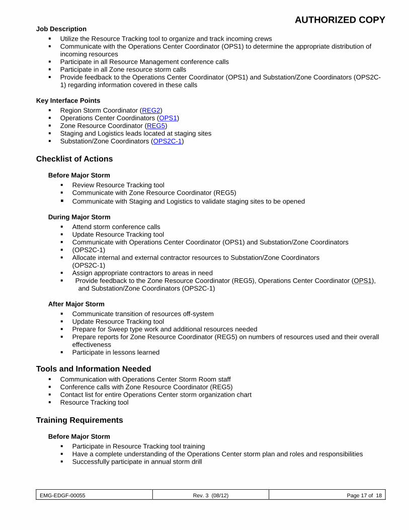
AUTHORIZED COPY
EMG-EDGF-00055 Rev. 3 (08/12) Page 17 of 18
Job Description Utilize the Resource Tracking tool to organize and track incoming crews Communicate with the Operations Center Coordinator (OPS1) to determine the appropriate distribution of
incoming resources Participate in all Resource Management conference calls Participate in all Zone resource storm calls Provide feedback to the Operations Center Coordinator (OPS1) and Substation/Zone Coordinators (OPS2C-
1) regarding information covered in these calls
Key Interface Points Region Storm Coordinator (REG2) Operations Center Coordinators (OPS1) Zone Resource Coordinator (REG5) Staging and Logistics leads located at staging sites Substation/Zone Coordinators (OPS2C-1)
Checklist of Actions
Before Major Storm Review Resource Tracking tool Communicate with Zone Resource Coordinator (REG5) Communicate with Staging and Logistics to validate staging sites to be opened
During Major Storm Attend storm conference calls Update Resource Tracking tool Communicate with Operations Center Coordinator (OPS1) and Substation/Zone Coordinators (OPS2C-1) Allocate internal and external contractor resources to Substation/Zone Coordinators
(OPS2C-1) Assign appropriate contractors to areas in need Provide feedback to the Zone Resource Coordinator (REG5), Operations Center Coordinator (OPS1),
and Substation/Zone Coordinators (OPS2C-1)
After Major Storm Communicate transition of resources off-system Update Resource Tracking tool Prepare for Sweep type work and additional resources needed Prepare reports for Zone Resource Coordinator (REG5) on numbers of resources used and their overall
effectiveness Participate in lessons learned
Tools and Information Needed Communication with Operations Center Storm Room staff Conference calls with Zone Resource Coordinator (REG5) Contact list for entire Operations Center storm organization chart Resource Tracking tool
Training Requirements
Before Major Storm Participate in Resource Tracking tool training Have a complete understanding of the Operations Center storm plan and roles and responsibilities Successfully participate in annual storm drill
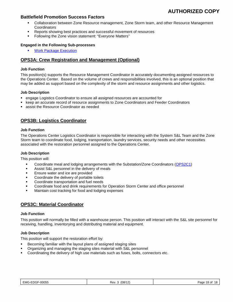
AUTHORIZED COPY
EMG-EDGF-00055 Rev. 3 (08/12) Page 18 of 18
Battlefield Promotion Success Factors Collaboration between Zone Resource management, Zone Storm team, and other Resource Management
Coordinators Reports showing best practices and successful movement of resources Following the Zone vision statement: “Everyone Matters”
Engaged in the Following Sub-processes Work Package Execution
OPS3A: Crew Registration and Management (Optional)
Job Function This position(s) supports the Resource Management Coordinator in accurately documenting assigned resources to the Operations Center. Based on the volume of crews and responsibilities involved, this is an optional position that may be added as support based on the complexity of the storm and resource assignments and other logistics.
Job Description engage Logistics Coordinator to ensure all assigned resources are accounted for keep an accurate record of resource assignments to Zone Coordinators and Feeder Coordinators assist the Resource Coordinator as needed
OPS3B: Logistics Coordinator
Job Function The Operations Center Logistics Coordinator is responsible for interacting with the System S&L Team and the Zone Storm team to coordinate food, lodging, transportation, laundry services, security needs and other necessities associated with the restoration personnel assigned to the Operations Center.
Job Description This position will: Coordinate meal and lodging arrangements with the Substation/Zone Coordinators (OPS2C1) Assist S&L personnel in the delivery of meals Ensure water and ice are provided Coordinate the delivery of portable toilets Coordinate transportation and fuel needs Coordinate food and drink requirements for Operation Storm Center and office personnel Maintain cost tracking for food and lodging expenses
OPS3C: Material Coordinator
Job Function This position will normally be filled with a warehouse person. This position will interact with the S&L site personnel for receiving, handling, inventorying and distributing material and equipment.
Job Description This position will support the restoration effort by: Becoming familiar with the layout plans of assigned staging sites Organizing and managing the staging sites material with S&L personnel Coordinating the delivery of high use materials such as fuses, bolts, connectors etc.
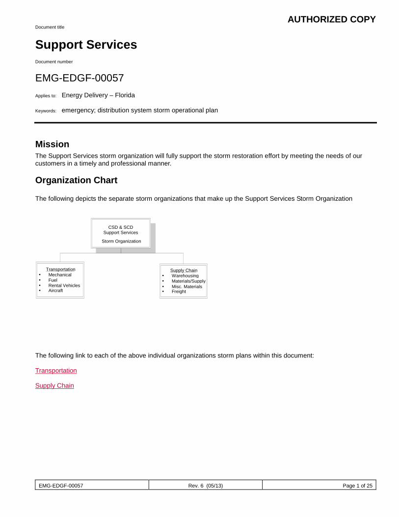
AUTHORIZED COPY
EMG-EDGF-00057 Rev. 6 (05/13) Page 1 of 25
Document title
Support Services Document number
EMG-EDGF-00057 Applies to: Energy Delivery – Florida Keywords: emergency; distribution system storm operational plan
Mission The Support Services storm organization will fully support the storm restoration effort by meeting the needs of our customers in a timely and professional manner.
Organization Chart The following depicts the separate storm organizations that make up the Support Services Storm Organization
The following link to each of the above individual organizations storm plans within this document: Transportation Supply Chain
CSD & SCD
Support Services Storm Organization
Transportation Mechanical Fuel Rental Vehicles Aircraft
Supply Chain Warehousing Materials/Supply Misc. Materials Freight
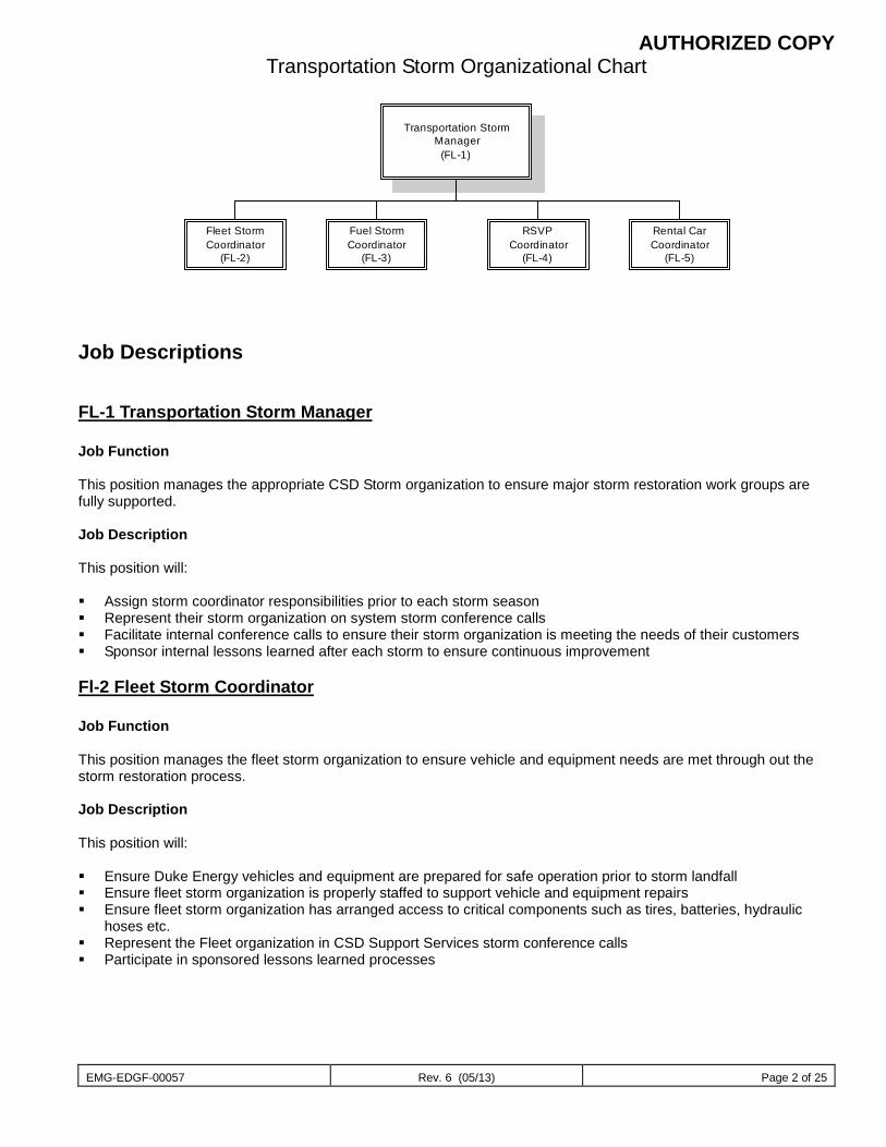
AUTHORIZED COPY
EMG-EDGF-00057 Rev. 6 (05/13) Page 2 of 25
Transportation Storm Organizational Chart
Transportation StormManager
(FL-1)
Fuel StormCoordinator
(FL-3)
RSVPCoordinator
(FL-4)
Fleet StormCoordinator
(FL-2)
Rental CarCoordinator
(FL-5)
Job Descriptions
FL-1 Transportation Storm Manager Job Function This position manages the appropriate CSD Storm organization to ensure major storm restoration work groups are fully supported. Job Description This position will: Assign storm coordinator responsibilities prior to each storm season Represent their storm organization on system storm conference calls Facilitate internal conference calls to ensure their storm organization is meeting the needs of their customers Sponsor internal lessons learned after each storm to ensure continuous improvement
Fl-2 Fleet Storm Coordinator Job Function This position manages the fleet storm organization to ensure vehicle and equipment needs are met through out the storm restoration process. Job Description This position will: Ensure Duke Energy vehicles and equipment are prepared for safe operation prior to storm landfall Ensure fleet storm organization is properly staffed to support vehicle and equipment repairs Ensure fleet storm organization has arranged access to critical components such as tires, batteries, hydraulic
hoses etc. Represent the Fleet organization in CSD Support Services storm conference calls Participate in sponsored lessons learned processes
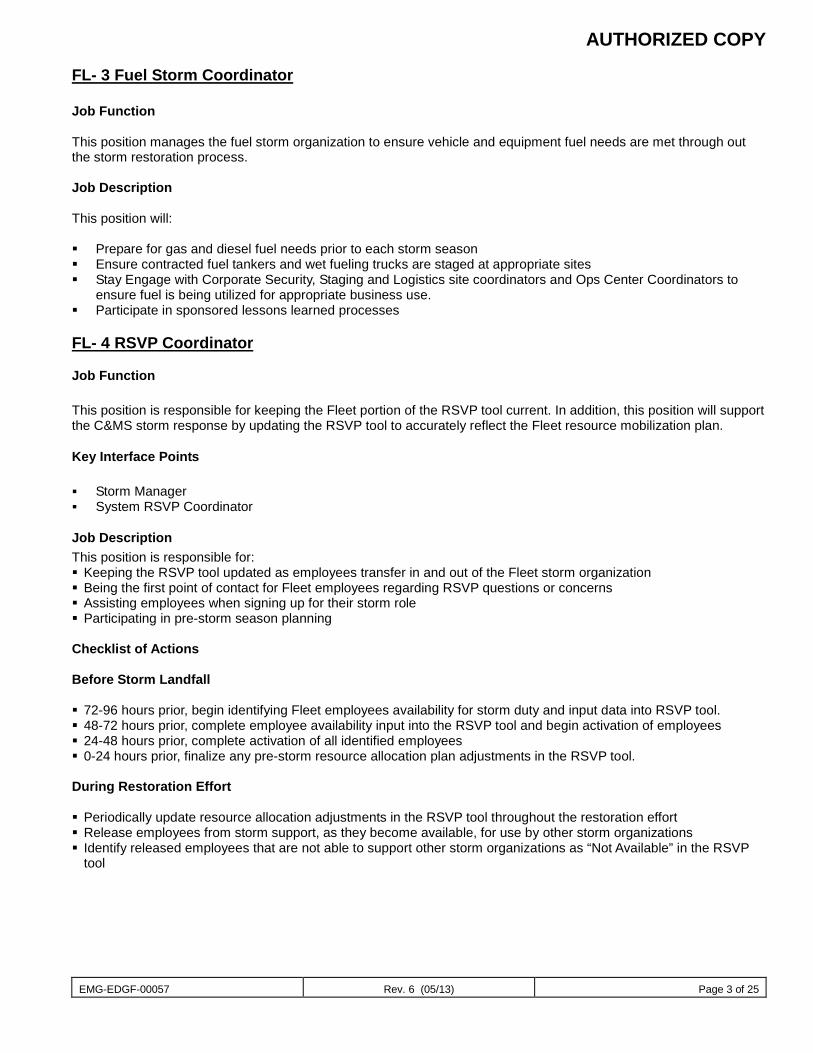
AUTHORIZED COPY
EMG-EDGF-00057 Rev. 6 (05/13) Page 3 of 25
FL- 3 Fuel Storm Coordinator Job Function This position manages the fuel storm organization to ensure vehicle and equipment fuel needs are met through out the storm restoration process. Job Description This position will: Prepare for gas and diesel fuel needs prior to each storm season Ensure contracted fuel tankers and wet fueling trucks are staged at appropriate sites Stay Engage with Corporate Security, Staging and Logistics site coordinators and Ops Center Coordinators to
ensure fuel is being utilized for appropriate business use. Participate in sponsored lessons learned processes
FL- 4 RSVP Coordinator
Job Function This position is responsible for keeping the Fleet portion of the RSVP tool current. In addition, this position will support the C&MS storm response by updating the RSVP tool to accurately reflect the Fleet resource mobilization plan.
Key Interface Points Storm Manager System RSVP Coordinator
Job Description This position is responsible for: Keeping the RSVP tool updated as employees transfer in and out of the Fleet storm organization Being the first point of contact for Fleet employees regarding RSVP questions or concerns Assisting employees when signing up for their storm role Participating in pre-storm season planning Checklist of Actions Before Storm Landfall 72-96 hours prior, begin identifying Fleet employees availability for storm duty and input data into RSVP tool. 48-72 hours prior, complete employee availability input into the RSVP tool and begin activation of employees 24-48 hours prior, complete activation of all identified employees 0-24 hours prior, finalize any pre-storm resource allocation plan adjustments in the RSVP tool. During Restoration Effort Periodically update resource allocation adjustments in the RSVP tool throughout the restoration effort Release employees from storm support, as they become available, for use by other storm organizations Identify released employees that are not able to support other storm organizations as “Not Available” in the RSVP
tool
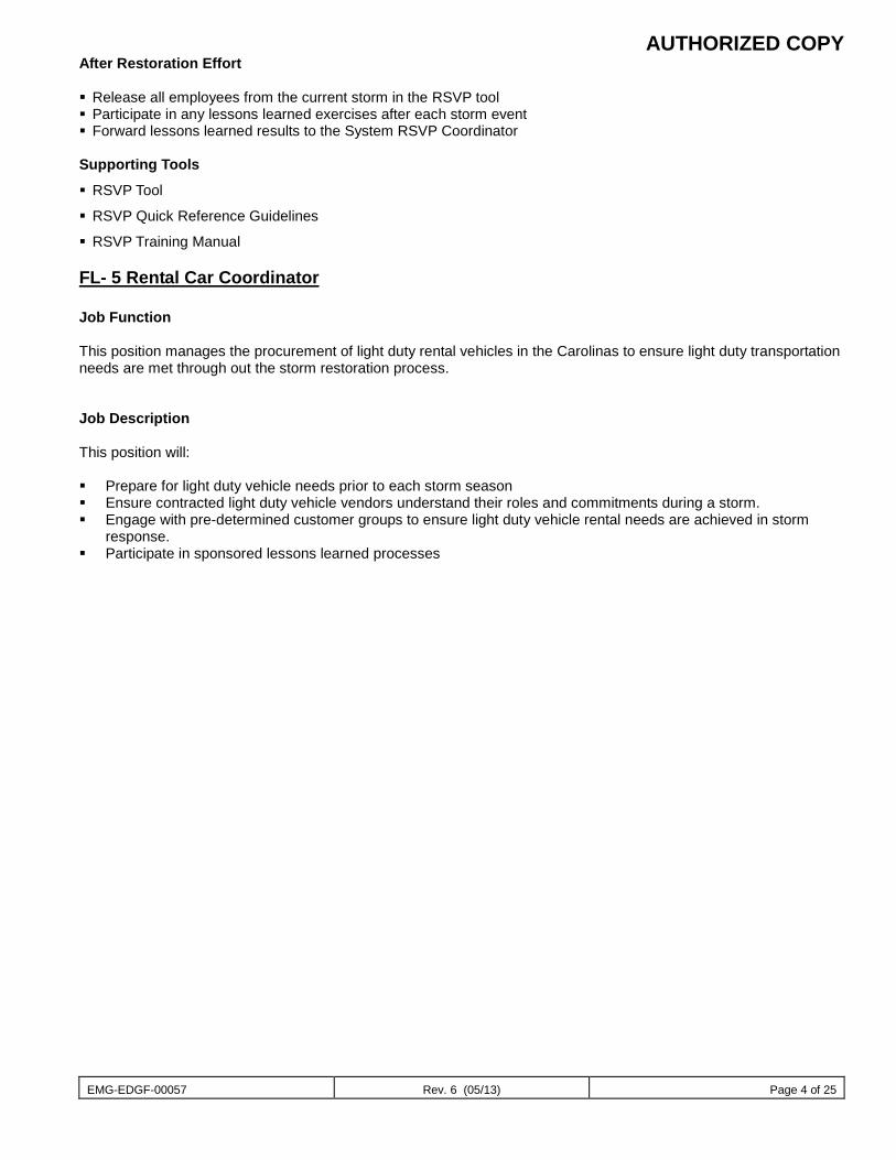
AUTHORIZED COPY
EMG-EDGF-00057 Rev. 6 (05/13) Page 4 of 25
After Restoration Effort Release all employees from the current storm in the RSVP tool Participate in any lessons learned exercises after each storm event Forward lessons learned results to the System RSVP Coordinator Supporting Tools
RSVP Tool
RSVP Quick Reference Guidelines
RSVP Training Manual
FL- 5 Rental Car Coordinator Job Function This position manages the procurement of light duty rental vehicles in the Carolinas to ensure light duty transportation needs are met through out the storm restoration process. Job Description This position will: Prepare for light duty vehicle needs prior to each storm season Ensure contracted light duty vehicle vendors understand their roles and commitments during a storm. Engage with pre-determined customer groups to ensure light duty vehicle rental needs are achieved in storm
response. Participate in sponsored lessons learned processes
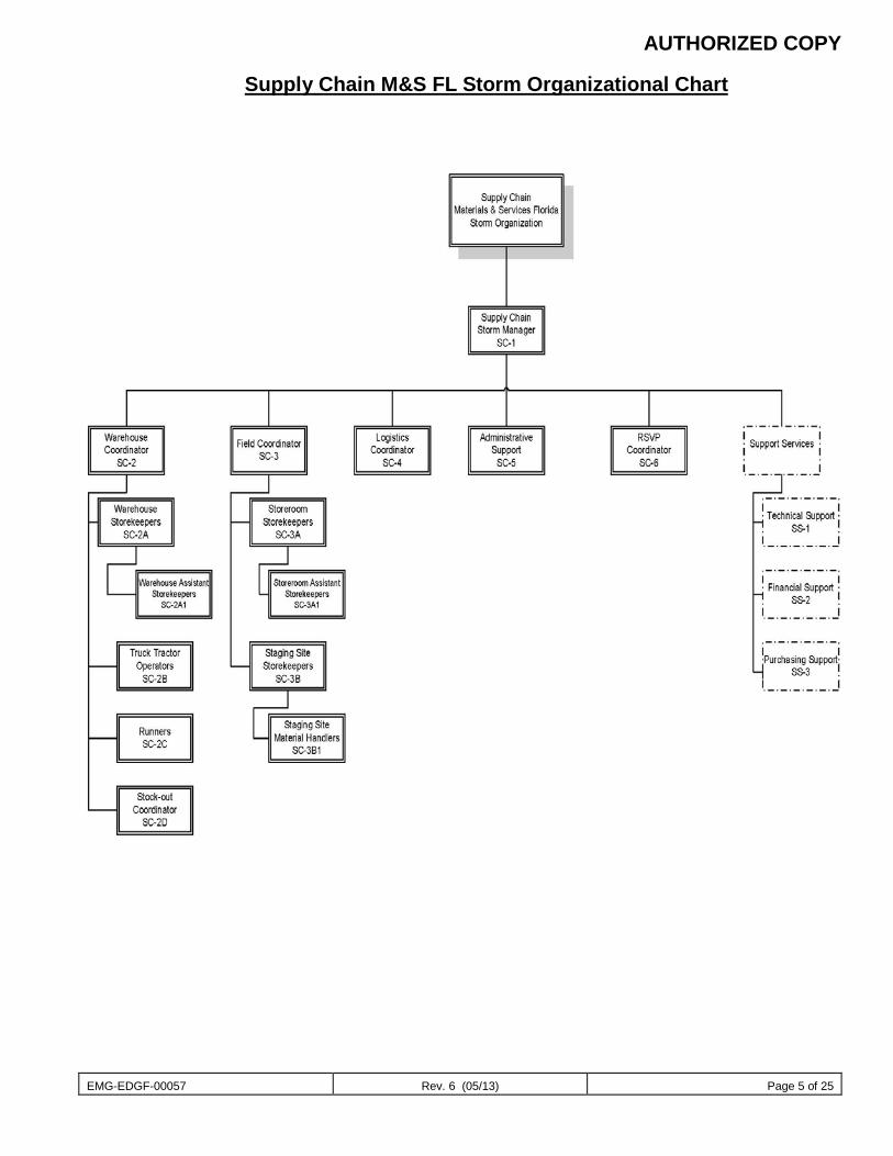
AUTHORIZED COPY
EMG-EDGF-00057 Rev. 6 (05/13) Page 5 of 25
Supply Chain M&S FL Storm Organizational Chart
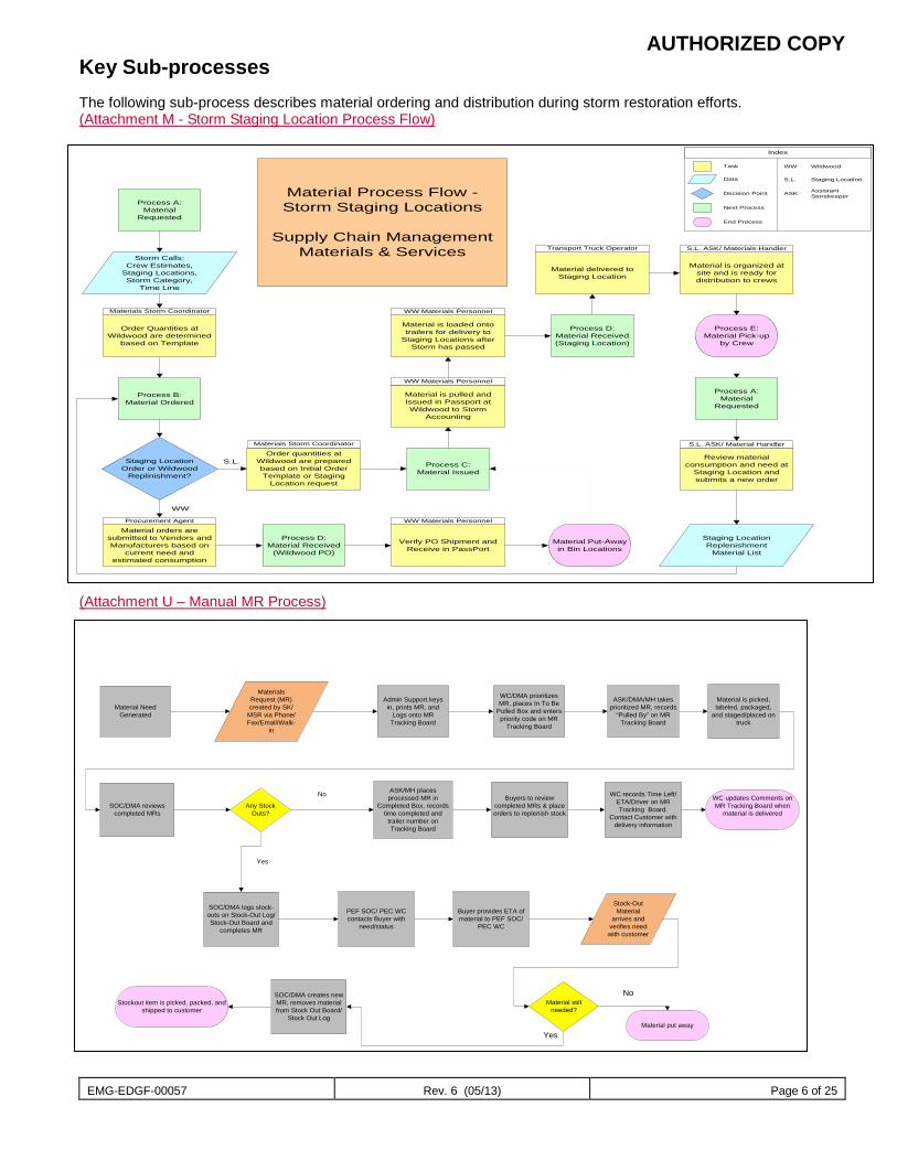
AUTHORIZED COPY
EMG-EDGF-00057 Rev. 6 (05/13) Page 6 of 25
Key Sub-processes The following sub-process describes material ordering and distribution during storm restoration efforts. (Attachment M - Storm Staging Location Process Flow) (Attachment U – Manual MR Process)
Material Need Generated
Materials Request (MR) created by SK/
MSR via Phone/Fax/Email/Walk-
in
Admin Support keys in, prints MR, and
Logs onto MR Tracking Board
WC/DMA prioritizes MR, places In To Be
Pulled Box and enters priority code on MR
Tracking Board
ASK/DMA/MH takes prioritized MR, records
“Pulled By” on MR Tracking Board
Material is picked, labeled, packaged,
and staged/placed on truck
ASK/MH places processed MR in
Completed Box, records time completed and
trailer number on Tracking Board
WC records Time Left/ETA/Driver on MR Tracking Board.
Contact Customer with delivery information
SOC/DMA reviews completed MRs
SOC/DMA logs stock-outs on Stock-Out Log/Stock-Out Board and
completes MR
Any Stock Outs?
PEF SOC/ PEC WC contacts Buyer with
need/status
Stock-Out Material
arrives and verifies need with customer
Material still needed?
Material put away
Yes
No
No
Yes
Buyer provides ETA of material to PEF SOC/
PEC WC
Stockout item is picked, packed, and shipped to customer
SOC/DMA creates new MR, removes material from Stock Out Board/
Stock Out Log
Buyers to review completed MRs & place orders to replenish stock
WC updates Comments on MR Tracking Board when
material is delivered
Process A:Material
Requested
Order quantities at Wildwood are prepared based on Initial Order Template or Staging
Location request
Material orders are submitted to Vendors and Manufacturers based on
current need and estimated consumption
Process D:Material Received
(Wildwood PO)
Verify PO Shipment and Receive in PassPort
Process D:Material Received(Staging Location)
Material delivered to Staging Location
Process E:Material Pick-up
by Crew
Material Process Flow - Storm Staging Locations
Supply Chain ManagementMaterials & ServicesStorm Calls:
Crew Estimates, Staging Locations, Storm Category,
Time Line
Order Quantities at Wildwood are determined
based on Template
Process B:Material Ordered
Staging Location Order or Wildwood
Replinishment?
S.L.
WW
Process C:Material Issued
Material Put-Away in Bin Locations
Material is pulled and Issued in Passport at Wildwood to Storm
Accounting
Material is loaded onto trailers for delivery to
Staging Locations after Storm has passed
Material is organized at site and is ready for distribution to crews
Review material consumption and need at
Staging Location and submits a new order
Process A:Material
Requested
Staging Location Replenishment
Material List
Task
Decision Point
Next Process
End Process
Data
Index
Materials Storm Coordinator
Materials Storm Coordinator
Procurement Agent WW Materials Personnel
Transport Truck Operator S.L. ASK/ Materials Handler
WW Materials Personnel
WW Materials Personnel
WW
S.L.
Wildwood
Staging Location
S.L. ASK/ Material Handler
ASK Assistant Storekeeper
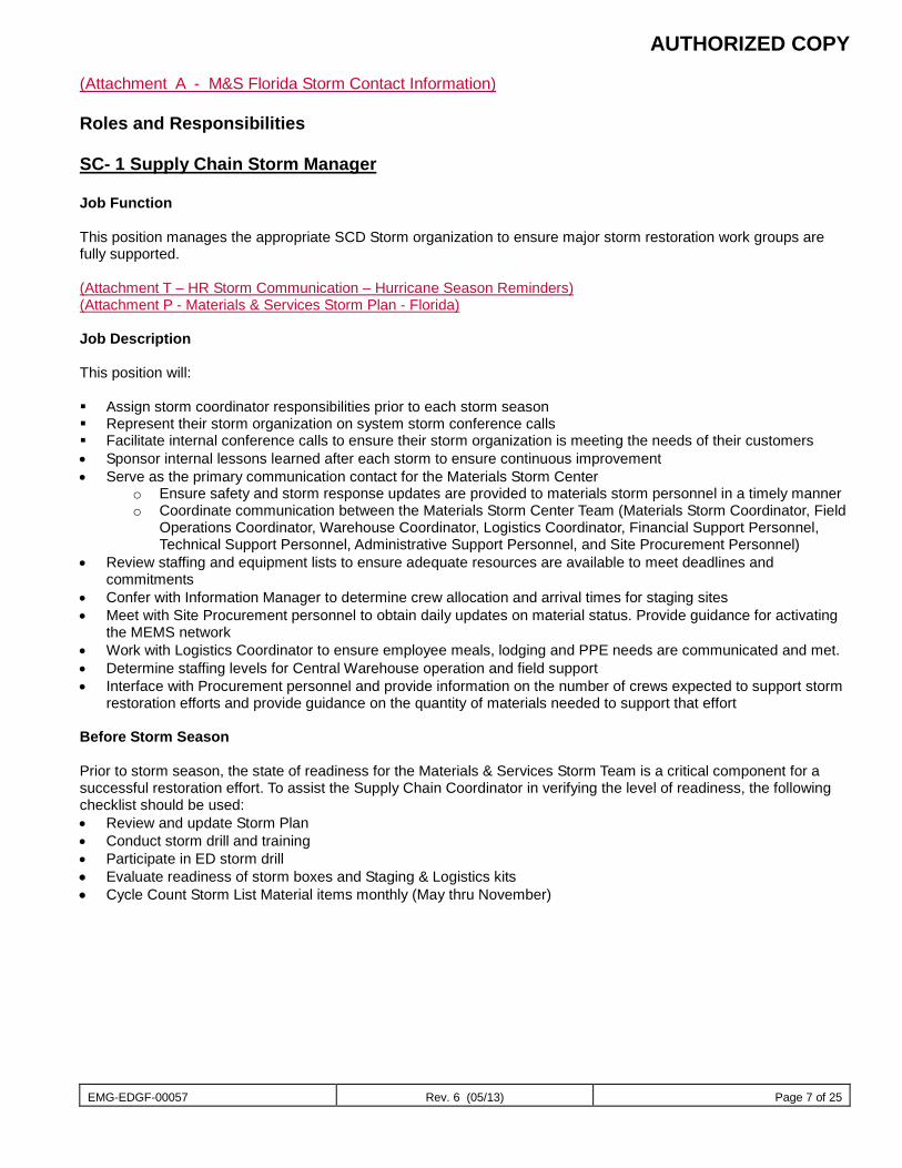
AUTHORIZED COPY
EMG-EDGF-00057 Rev. 6 (05/13) Page 7 of 25
(Attachment A - M&S Florida Storm Contact Information) Roles and Responsibilities SC- 1 Supply Chain Storm Manager Job Function This position manages the appropriate SCD Storm organization to ensure major storm restoration work groups are fully supported. (Attachment T – HR Storm Communication – Hurricane Season Reminders) (Attachment P - Materials & Services Storm Plan - Florida) Job Description This position will: Assign storm coordinator responsibilities prior to each storm season Represent their storm organization on system storm conference calls Facilitate internal conference calls to ensure their storm organization is meeting the needs of their customers • Sponsor internal lessons learned after each storm to ensure continuous improvement • Serve as the primary communication contact for the Materials Storm Center
o Ensure safety and storm response updates are provided to materials storm personnel in a timely manner o Coordinate communication between the Materials Storm Center Team (Materials Storm Coordinator, Field
Operations Coordinator, Warehouse Coordinator, Logistics Coordinator, Financial Support Personnel, Technical Support Personnel, Administrative Support Personnel, and Site Procurement Personnel)
• Review staffing and equipment lists to ensure adequate resources are available to meet deadlines and commitments
• Confer with Information Manager to determine crew allocation and arrival times for staging sites • Meet with Site Procurement personnel to obtain daily updates on material status. Provide guidance for activating
the MEMS network • Work with Logistics Coordinator to ensure employee meals, lodging and PPE needs are communicated and met. • Determine staffing levels for Central Warehouse operation and field support • Interface with Procurement personnel and provide information on the number of crews expected to support storm
restoration efforts and provide guidance on the quantity of materials needed to support that effort Before Storm Season Prior to storm season, the state of readiness for the Materials & Services Storm Team is a critical component for a successful restoration effort. To assist the Supply Chain Coordinator in verifying the level of readiness, the following checklist should be used: • Review and update Storm Plan • Conduct storm drill and training • Participate in ED storm drill • Evaluate readiness of storm boxes and Staging & Logistics kits • Cycle Count Storm List Material items monthly (May thru November)
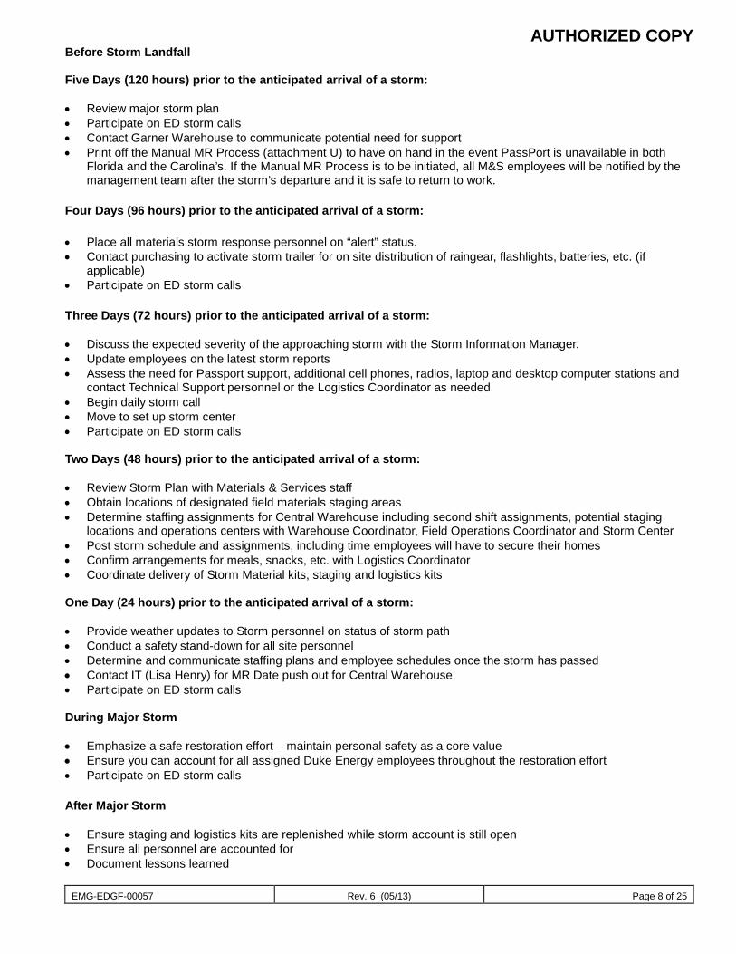
AUTHORIZED COPY
EMG-EDGF-00057 Rev. 6 (05/13) Page 8 of 25
Before Storm Landfall Five Days (120 hours) prior to the anticipated arrival of a storm: • Review major storm plan • Participate on ED storm calls • Contact Garner Warehouse to communicate potential need for support • Print off the Manual MR Process (attachment U) to have on hand in the event PassPort is unavailable in both
Florida and the Carolina’s. If the Manual MR Process is to be initiated, all M&S employees will be notified by the management team after the storm’s departure and it is safe to return to work.
Four Days (96 hours) prior to the anticipated arrival of a storm: • Place all materials storm response personnel on “alert” status. • Contact purchasing to activate storm trailer for on site distribution of raingear, flashlights, batteries, etc. (if
applicable) • Participate on ED storm calls Three Days (72 hours) prior to the anticipated arrival of a storm: • Discuss the expected severity of the approaching storm with the Storm Information Manager. • Update employees on the latest storm reports • Assess the need for Passport support, additional cell phones, radios, laptop and desktop computer stations and
contact Technical Support personnel or the Logistics Coordinator as needed • Begin daily storm call • Move to set up storm center • Participate on ED storm calls Two Days (48 hours) prior to the anticipated arrival of a storm: • Review Storm Plan with Materials & Services staff • Obtain locations of designated field materials staging areas • Determine staffing assignments for Central Warehouse including second shift assignments, potential staging
locations and operations centers with Warehouse Coordinator, Field Operations Coordinator and Storm Center • Post storm schedule and assignments, including time employees will have to secure their homes • Confirm arrangements for meals, snacks, etc. with Logistics Coordinator • Coordinate delivery of Storm Material kits, staging and logistics kits One Day (24 hours) prior to the anticipated arrival of a storm: • Provide weather updates to Storm personnel on status of storm path • Conduct a safety stand-down for all site personnel • Determine and communicate staffing plans and employee schedules once the storm has passed • Contact IT (Lisa Henry) for MR Date push out for Central Warehouse • Participate on ED storm calls During Major Storm • Emphasize a safe restoration effort – maintain personal safety as a core value • Ensure you can account for all assigned Duke Energy employees throughout the restoration effort • Participate on ED storm calls After Major Storm • Ensure staging and logistics kits are replenished while storm account is still open • Ensure all personnel are accounted for • Document lessons learned
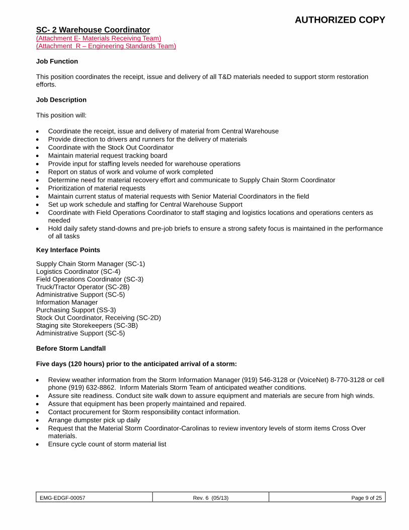
AUTHORIZED COPY
EMG-EDGF-00057 Rev. 6 (05/13) Page 9 of 25
SC- 2 Warehouse Coordinator (Attachment E- Materials Receiving Team) (Attachment R – Engineering Standards Team) Job Function This position coordinates the receipt, issue and delivery of all T&D materials needed to support storm restoration efforts. Job Description This position will: • Coordinate the receipt, issue and delivery of material from Central Warehouse • Provide direction to drivers and runners for the delivery of materials • Coordinate with the Stock Out Coordinator • Maintain material request tracking board • Provide input for staffing levels needed for warehouse operations • Report on status of work and volume of work completed • Determine need for material recovery effort and communicate to Supply Chain Storm Coordinator • Prioritization of material requests • Maintain current status of material requests with Senior Material Coordinators in the field • Set up work schedule and staffing for Central Warehouse Support • Coordinate with Field Operations Coordinator to staff staging and logistics locations and operations centers as
needed • Hold daily safety stand-downs and pre-job briefs to ensure a strong safety focus is maintained in the performance
of all tasks Key Interface Points Supply Chain Storm Manager (SC-1) Logistics Coordinator (SC-4) Field Operations Coordinator (SC-3) Truck/Tractor Operator (SC-2B) Administrative Support (SC-5) Information Manager Purchasing Support (SS-3) Stock Out Coordinator, Receiving (SC-2D) Staging site Storekeepers (SC-3B) Administrative Support (SC-5) Before Storm Landfall Five days (120 hours) prior to the anticipated arrival of a storm: • Review weather information from the Storm Information Manager (919) 546-3128 or (VoiceNet) 8-770-3128 or cell
phone (919) 632-8862. Inform Materials Storm Team of anticipated weather conditions. • Assure site readiness. Conduct site walk down to assure equipment and materials are secure from high winds. • Assure that equipment has been properly maintained and repaired. • Contact procurement for Storm responsibility contact information. • Arrange dumpster pick up daily • Request that the Material Storm Coordinator-Carolinas to review inventory levels of storm items Cross Over
materials. • Ensure cycle count of storm material list
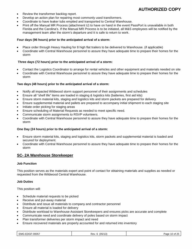
AUTHORIZED COPY
EMG-EDGF-00057 Rev. 6 (05/13) Page 10 of 25
• Review the transformer backlog report. • Develop an action plan for repairing most commonly used transformers. • Coordinate to have leaker tubs emptied and transported to Central Warehouse. • Print off the Manual MR Process (attachment U) to have on hand in the event PassPort is unavailable in both
Florida and the Carolina’s. If the Manual MR Process is to be initiated, all M&S employees will be notified by the management team after the storm’s departure and it is safe to return to work.
Four days (96 hours) prior to the anticipated arrival of a storm: • Place order through Heavy Hauling for 8 high flat trailers to be delivered to Warehouse. (if applicable) • Coordinate with Central Warehouse personnel to assure they have adequate time to prepare their homes for the
storm Three days (72 hours) prior to the anticipated arrival of a storm: • Contact the Logistics Coordinator to arrange for rental vehicles and other equipment and materials needed on site • Coordinate with Central Warehouse personnel to assure they have adequate time to prepare their homes for the
storm Two days (48 hours) prior to the anticipated arrival of a storm: • Notify all impacted Wildwood storm support personnel of their assignments and schedules • Ensure all “shelf life” items are loaded in staging & logistics kits (batteries, first aid kits) • Ensure storm material kits, staging and logistics kits and storm packets are prepared for delivery. • Ensure supplemental material and pallets are prepared to accompany initial shipment to each staging site • Initiate order picking for staging areas • Ensure scheduling of Material Requests as needed to meet specific need. • Communicate storm assignments to RSVP volunteers. • Coordinate with Central Warehouse personnel to assure they have adequate time to prepare their homes for the
storm One Day (24 hours) prior to the anticipated arrival of a storm: • Ensure storm material kits, staging and logistics kits, storm packets and supplemental material is loaded and
secured for deployment. • Coordinate with Central Warehouse personnel to assure they have adequate time to prepare their homes for the
storm SC- 2A Warehouse Storekeeper Job Function This position serves as the materials expert and point of contact for obtaining materials and supplies as needed or requested from the Wildwood Central Warehouse. Job Duties This position will: • Schedule material requests to be picked • Receive and put-away material • Distribute and issue all materials to company and contractor personnel • Ensure all material is loaded for delivery • Distribute workload to Warehouse Assistant Storekeepers and ensures picks are accurate and complete • Communicate need and coordinate delivery of poles based on storm impact • Plan transformer deliveries per storm impact and need • Ensure recovered materials are properly accounted for and returned into inventory
AUTHORIZED COPY
EMG-EDGF-00057 Rev. 6 (05/13) Page 11 of 25
Key Interface Points • Warehouse Coordinator (SC-2) • Truck/Tractor Operator (SC-2B) • Runners (SC-2C) • Administrative Support (SC-5) • Warehouse Assistant Storekeepers (SC-3A1) • Staging Site Storekeepers (SC-3B) • Storeroom Storekeepers (SC-3A) • Company and contractor personnel Before Storm Landfall Five Days (120 hours) prior to the anticipated arrival of a storm: • Conduct site walk downs and secure equipment and materials from high winds • Review fuel requirements for forklift trucks • Communicate with Supply Chain Coordinator to ensure storm readiness • Review storm plan and responsibilities • Review storm stock to ensure sufficient material levels • Receive and pick material requests as needed Four days (96 hours) prior to the anticipated arrival of a storm: • Receive and pick material requests as needed Two days (48 hours) prior to the anticipated arrival of a storm: • Receive and pick material requests as needed • Ensure forklifts are fueled and operationally ready After Major Storm • Account for any recovered material that has been returned to the Central Warehouse SC- 2A1 Warehouse Assistant Storekeeper (Attachment F - Materials Picking Team) Job Function This position supports the Warehouse Storekeeper at the Wildwood Central Warehouse with materials handling and readiness. Job Duties This position will: • Assist Warehouse Storekeeper with site readiness and storm preparation at the Wildwood Central Warehouse • Assist with material ordering, receiving and put-away • Assist with material distribution to company and contractor personnel • Assist with material recovery effort as needed • Assist with site maintenance as needed Key Interface Points • Warehouse Coordinator (SC-2) • Company and contractor personnel • Truck/Tractor Operator (SC-2B) • Runners (SC-2C)
AUTHORIZED COPY
EMG-EDGF-00057 Rev. 6 (05/13) Page 12 of 25
• Administrative Support (SC-5) • Staging Site Storekeepers (SC-3B) • Storeroom Storekeepers (SC-3A) • Warehouse Storekeepers (SC-3A)Before Storm Landfall Five Days (120 hours) prior to the anticipated arrival of a storm: • Review storm plan and responsibilities SC- 2B Truck/Tractor Operator (Attachment J- Transport Truck Operators) Job Function This position loads and delivers materials from the Wildwood Central Warehouse to staging sites and Regional Storerooms, and transports materials back to the Central Warehouse from outlying locations. Job Description This position will: • Load and transport materials from Wildwood Central Warehouse to staging sites and Regional Storerooms • Transport returns and recovered material to the Wildwood Central Warehouse • Ensure Tractor/Trailer is operated in a safe manner, consistent with company policies and procedures • Comply with all DOT rules and regulations Key Interface Points • Warehouse Coordinator (SC-2) • Warehouse Storekeeper (SC-3A) • Warehouse Assistant Storekeeper (SC-3A1) • Staging site Storekeeper (SC-3B)
SC- 2C Runners Attachment W- Tree Ground Acquisition Process Job Function This position delivers small quantities of critical materials to staging sites and operations centers on an as needed basis. Job Description This position will: • Operate standard pick-up, SUV or other motor vehicle • Promptly deliver materials to site as requested • Assist with material recovery and site maintenance as required Key Interface Points • Warehouse Coordinator (SC-2A) • Staging site Storekeeper (SC-3B) • Warehouse Storekeeper (SC-3A) • Warehouse Assistant Storekeeper (SC-3A1)
AUTHORIZED COPY
EMG-EDGF-00057 Rev. 6 (05/13) Page 13 of 25
SC- 2D Stock-out Coordinator Job Function This position ensures that material stock-outs are followed up on. Job Duties This position will: • Serve as the point of contact for all stock out items • Make a list of all stock out materials and requesting locations • Make arrangements with the Warehouse Coordinator on delivery of stock out material when it is ready to be
shipped to locations • Contact the receiving team to make them aware of material that will be needed to fill stock outs (stock out board) • Contact procurement representatives for the need of additional material • Contact recovery personnel on need for stock out material • Review all material requests with stock out items and set status to complete • Check with Standards to see if any substitution of material that is stocked out can be made • Follow up with requesting location to ensure need is still valid Key Interface Points • Warehouse Coordinator (SC-2) • Warehouse Personnel • Procurement Support • Recovery Personnel • Vendor Representative SC- 3 Field Operations Coordinator and Distribution Planners Job Function This position is responsible for the staffing and operations of T&D Storerooms and materials support at Staging Areas in support of storm restoration efforts. Job Description This position will: • Understand current material support needed from T&D Storerooms and staging sites • Develop staffing plan, communicate and implement in support of storm restoration needs • Coordinate with Logistics Coordinator to staff staging and logistics locations and operations centers as needed • Establish communications with the Staging Site Storekeeper to stay informed of any changes in the number of
crews assigned to a particular site • Confer with Regional Energy Delivery Coordinator to determine crew allocation and arrival times for staging sites • Monitor and support materials personnel needs at field locations. Have equipment needed, ensure safety and
storm briefings are occurring, material management protocols are being followed, personnel housing and meals needs are being met, staffing at materials locations is adequate
• Be visible in Regional Storm Center • Address issues as needed with Staging and Logistics Team Lead at staging areas and DOMs at operation centers Key Interface Points • Supply Chain Storm Manager (SC-1) • Regional ED Storm coordinator Manager • Warehouse Coordinator (SC-2)
AUTHORIZED COPY
EMG-EDGF-00057 Rev. 6 (05/13) Page 14 of 25
• Purchasing Support (SS-3) • Material Handlers (SC-3B1) • Warehouse Storekeepers (SC-2A) • Logistics Coordinator (SC-4) Before Storm Season • Review storm readiness of materials organization and material levels at operation centers. • Ensure adequate supplies of fuses, splices, squeeze-on connectors and any other special need materials (coastal
areas) 3 day supply • Ensure that financial kits are current and that every employee has one. • Designate a back-up Field Operations Coordinator. • Confirm field kits locations
o South - Lake Wales and Seven Springs o North - Monticello and Apopka
Before Storm Landfall Five Days (120 hours) prior to the anticipated arrival of a storm: • Assure Regional Storeroom site readiness. • Assure that site walks down are conducted and that equipment and materials are secure from high winds • Assure that additional fuel for forklift trucks is obtained • Begin increased information and communication with Regional Storeroom personnel • Inspect, review and place orders to top off materials. • Review Major Storm Plan with all employees. • Have Storekeepers to make all orders from Wildwood (crossdocking). • Participate on ED storm calls • Print off the Manual MR Process (attachment U) to have on hand in the event PassPort is unavailable in both
Florida and the Carolina’s. If the Manual MR Process is to be initiated, all M&S employees will be notified by the management team after the storm’s departure and it is safe to return to work.
Four days (96 hours) prior to the anticipated arrival of a storm: • Ensure storm readiness of materials organization and material levels at operation centers. • Begin daily storm calls with Regional Storeroom personnel. • Assure materials stored at the Regional Storeroom yards have been secured from high winds. • Ensure that Regional Storeroom personnel understand their storm responsibilities after the storm has passed. • Update Regional Storeroom personnel contact information. • Participate on ED storm calls • Coordinate with personnel to assure they have adequate time to prepare their homes for the storm Three days (72 hours) prior to the anticipated arrival of a storm: • Review job responsibilities and assignments with all employees • Participate on ED storm calls • Coordinate with personnel to assure they have adequate time to prepare their homes for the storm
Two days (48 hours) prior to the anticipated arrival of a storm: • Notify all impacted storm support personnel of their potential assignments and schedules • Assign and schedule storm material kits and staging and logistics kit to each staging site • Ensure Material Requests are submitted as needed to meet specific need • Communicate storm assignments and vehicles to material handlers and runners. • Inform Regional Storeroom personnel at operations centers of staging areas to be opened close to them. • Coordinate with Regional Storeroom personnel to have all Stores vehicles readied and fueled.
AUTHORIZED COPY
EMG-EDGF-00057 Rev. 6 (05/13) Page 15 of 25
• Obtain names of employees assigned from the S&L Teams who will be supporting materials activities at Staging and Logistics site and/or Regional Storerooms.
• Determine staffing levels for potential Staging sites • Participate on ED storm calls • Coordinate with personnel to assure they have adequate time to prepare their homes for the storm One Day (24 hours) prior to the anticipated arrival of a storm: • Coordinate with personnel to assure they have adequate time to prepare their homes for the storm. • Participate on ED storm calls After Major Storm • Replenish storm materials kits while storm account is still open • Participate on ED storm calls SC- 3A Storeroom Storekeeper Attachment W- Tree Ground Acquisition Process Job Function This position serves as the materials expert and point of contact for obtaining materials and supplies as needed or requested for the Regional Storeroom. Job Duties This position will: • Create material requests into Passport for Regional Storeroom and Staging Sites • Receive and put-away material • Distribute and issue all materials to company and contractor personnel • Communicate need and coordinate delivery of poles based on storm impact • Plan transformer deliveries per storm impact and need • Coordinate local material recovery effort Key Interface Points • Field Operations Coordinator (SC-3) • Company and contractor personnel • Warehouse Coordinator (SC-2) • Truck/Tractor Operator (SC-2B) • Administrative Support (SC-5) • Storeroom Assistant Storekeepers (SC-3A1) • Staging Site Storekeepers (SC-3B)
AUTHORIZED COPY
EMG-EDGF-00057 Rev. 6 (05/13) Page 16 of 25
Before Storm Landfall Five Days (120 hours) prior to the anticipated arrival of a storm: • Conduct site walk downs secure equipment and materials from high winds • Review fuel requirements for forklift trucks • Communicate with Field Operations Coordinator to ensure storm readiness • Review storm plan and responsibilities • Review storm stock to ensure sufficient material levels at Regional Storeroom • Submit material requests as needed Four days (96 hours) prior to the anticipated arrival of a storm: • Submit material requests as needed Two days (48 hours) prior to the anticipated arrival of a storm: • Submit material requests as needed • Prepare and fuel company vehicle(s) After Major Storm • Replenish storm materials kits while storm account is still open • Prepare excess, salvage and scrap materials for return to Warehouse or local operations center SC-3A1 Storeroom Assistant Storekeeper Job Function This position supports the Storeroom Storekeeper at the Regional Storeroom with materials handling and readiness. Job Duties This position will: • Assist Storeroom Storekeeper with site readiness and storm preparation at the Regional Storeroom • Assist with material ordering, receiving and put-away • Assist with material distribution to company and contractor personnel • Assist with material recovery effort as needed • Assist with site maintenance as needed Key Interface Points • Field Operations Coordinator (SC-3) • Company and contractor personnel • Truck/Tractor Operator (SC-2B) • Administrative Support (SC-5) • Staging Site Storekeepers (SC-3B) • Storeroom Storekeepers (SC-3A) Before Storm Landfall Five Days (120 hours) prior to the anticipated arrival of a storm: • Review storm plan and responsibilities
AUTHORIZED COPY
EMG-EDGF-00057 Rev. 6 (05/13) Page 17 of 25
SC- 3B Staging Site Storekeeper (Attachment C - Staging Support – to be updated 48 hours prior to the storm) Job Function This position serves as the materials expert and single point of contact for obtaining materials and supplies as needed or requested by staging site team leader or designee. (Attachment K - Field Materials Staging Template) (Attachment L- Staging & Logistics Kit List) (Attachment N - Storm Materials Kit List) Closing of Staging Site after Storm (Attachment G - Materials Pickup & Return Procedures for Staging Site Operations) Job Duties This position will: • Lay out / set up material at staging site • Determine the most efficient storage layout for materials in order to minimize traffic congestion and confusion • Issue all materials and equipment from the Staging & Logistics kits • Monitor and issue all materials from the S&L kits to site personnel • Coordinate need and delivery of poles based on storm impact • Plan transformer deliveries per storm impact and need • Monitor material usage and place replenishment orders for all materials and equipment • Order, receive, separate and distribute material • Serve as a point of contact for procuring materials, equipment and supplies as needed • Prepare excess, salvage and scrap materials for return to Warehouse or local operations center • Record all materials and equipment used in the Staging and Logistics kit on the form provided in the Storm
Response Kit • Responsible for ensuring all materials and equipment have been removed from the staging site prior to departure. • Work with Field Coordinator to negotiate time to remove material • Return the Storm Response Kit to Central Warehouse Key Interface Points • Staging Site Team Leader • Field Operations Coordinator (SC-3) • Company and contractor personnel • Warehouse Coordinator (SC-2A) • Truck/Tractor Operator (SC-2B) • Administrative Support (SC-5) • Storeroom Storekeepers (SC-3A) • Staging Site Material Handlers (SC-3B1) Before Storm Landfall Four days (96 hours) prior to the anticipated arrival of a storm: • Review storm stock
AUTHORIZED COPY
EMG-EDGF-00057 Rev. 6 (05/13) Page 18 of 25
SC-3B1 Staging Site Material Handler Job Function This position supports the Staging Site Storekeeper at with materials handling and readiness at the Staging Site. Job Duties This position will: • Assist Staging Site Storekeeper with site preparation and setup • Assist with material ordering and receiving • Assist with material distribution to company and contractor personnel • Assist with material recovery effort as needed • Assist with site maintenance as needed • Assist with loading and unloading of all material shipments Key Interface Points • Field Operations Coordinator (SC-3) • Company and contractor personnel • Truck/Tractor Operator (SC-2B) • Staging Site Storekeepers (SC-3B) • Staging Site Team Leader • Storeroom Storekeepers (SC-3A) Before Storm Landfall Five Days (120 hours) prior to the anticipated arrival of a storm: • Review storm plan and responsibilities SC- 4 Logistics Coordinator (Attachment D- Wildwood Site Lodging and Meals Contact List) Job Function This position is responsible for ensuring that food, lodging, and equipment rental requirements are handled for personnel reporting to the Central Warehouse and Transformer Shop. Job Description This position will: • Contact local vendors to arrange for food to be brought on site • Make arrangements to prepare food on site when necessary • Ensure that drinks/snacks are available for site personnel during storm restoration • Contact local lodging establishments to provide adequate living arrangements for site support personnel during
storm restoration efforts • Contact Contracts representatives for equipment rental needs as identified by the Supply Chain Storm
Coordinator • Serve as the point of contact for security, safety and facility support
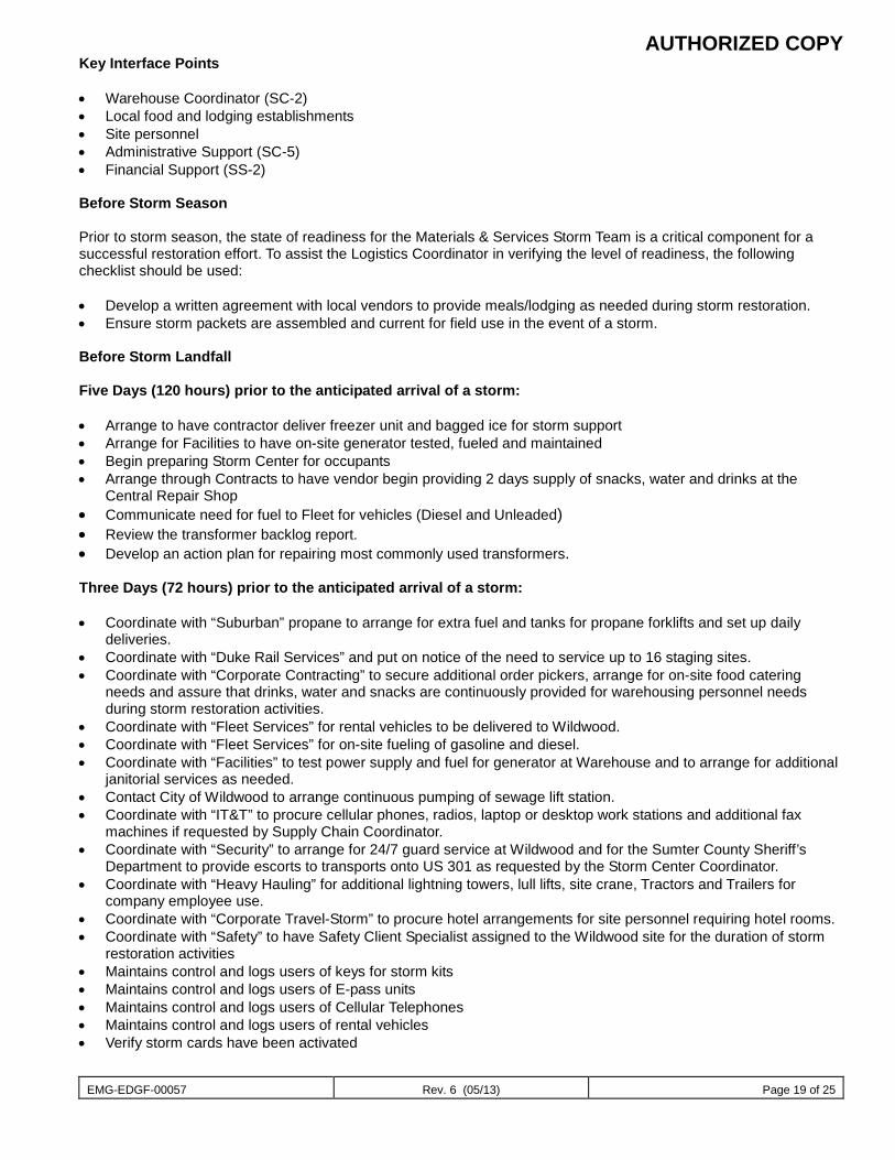
AUTHORIZED COPY
EMG-EDGF-00057 Rev. 6 (05/13) Page 19 of 25
Key Interface Points • Warehouse Coordinator (SC-2) • Local food and lodging establishments • Site personnel • Administrative Support (SC-5) • Financial Support (SS-2) Before Storm Season Prior to storm season, the state of readiness for the Materials & Services Storm Team is a critical component for a successful restoration effort. To assist the Logistics Coordinator in verifying the level of readiness, the following checklist should be used: • Develop a written agreement with local vendors to provide meals/lodging as needed during storm restoration. • Ensure storm packets are assembled and current for field use in the event of a storm. Before Storm Landfall Five Days (120 hours) prior to the anticipated arrival of a storm: • Arrange to have contractor deliver freezer unit and bagged ice for storm support • Arrange for Facilities to have on-site generator tested, fueled and maintained • Begin preparing Storm Center for occupants • Arrange through Contracts to have vendor begin providing 2 days supply of snacks, water and drinks at the
Central Repair Shop • Communicate need for fuel to Fleet for vehicles (Diesel and Unleaded) • Review the transformer backlog report. • Develop an action plan for repairing most commonly used transformers. Three Days (72 hours) prior to the anticipated arrival of a storm: • Coordinate with “Suburban” propane to arrange for extra fuel and tanks for propane forklifts and set up daily
deliveries. • Coordinate with “Duke Rail Services” and put on notice of the need to service up to 16 staging sites. • Coordinate with “Corporate Contracting” to secure additional order pickers, arrange for on-site food catering
needs and assure that drinks, water and snacks are continuously provided for warehousing personnel needs during storm restoration activities.
• Coordinate with “Fleet Services” for rental vehicles to be delivered to Wildwood. • Coordinate with “Fleet Services” for on-site fueling of gasoline and diesel. • Coordinate with “Facilities” to test power supply and fuel for generator at Warehouse and to arrange for additional
janitorial services as needed. • Contact City of Wildwood to arrange continuous pumping of sewage lift station. • Coordinate with “IT&T” to procure cellular phones, radios, laptop or desktop work stations and additional fax
machines if requested by Supply Chain Coordinator. • Coordinate with “Security” to arrange for 24/7 guard service at Wildwood and for the Sumter County Sheriff’s
Department to provide escorts to transports onto US 301 as requested by the Storm Center Coordinator. • Coordinate with “Heavy Hauling” for additional lightning towers, lull lifts, site crane, Tractors and Trailers for
company employee use. • Coordinate with “Corporate Travel-Storm” to procure hotel arrangements for site personnel requiring hotel rooms. • Coordinate with “Safety” to have Safety Client Specialist assigned to the Wildwood site for the duration of storm
restoration activities • Maintains control and logs users of keys for storm kits • Maintains control and logs users of E-pass units • Maintains control and logs users of Cellular Telephones • Maintains control and logs users of rental vehicles • Verify storm cards have been activated
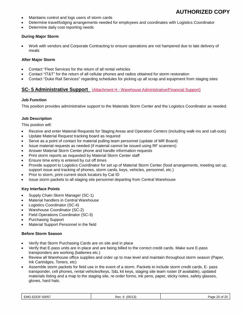
AUTHORIZED COPY
EMG-EDGF-00057 Rev. 6 (05/13) Page 20 of 25
• Maintains control and logs users of storm cards • Determine travel/lodging arrangements needed for employees and coordinates with Logistics Coordinator • Determine daily cost reporting needs During Major Storm • Work with vendors and Corporate Contracting to ensure operations are not hampered due to late delivery of
meals After Major Storm • Contact “Fleet Services for the return of all rental vehicles • Contact “IT&T” for the return of all cellular phones and radios obtained for storm restoration • Contact “Duke Rail Services” regarding schedules for picking up all scrap and equipment from staging sites SC- 5 Administrative Support (Attachment H - Warehouse Administrative/Financial Support) Job Function This position provides administrative support to the Materials Storm Center and the Logistics Coordinator as needed. Job Description This position will: • Receive and enter Material Requests for Staging Areas and Operation Centers (including walk-ins and call-outs) • Update Material Request tracking board as required • Serve as a point of contact for material pulling team personnel (update of MR Board) • Issue material requests as needed (if material cannot be issued using RF scanners) • Answer Material Storm Center phone and handle information requests • Print storm reports as requested by Material Storm Center staff • Ensure time entry is entered by cut off times • Provide support to Logistics Coordinator for set up of Material Storm Center (food arrangements, meeting set up,
support issue and tracking of phones, storm cards, keys, vehicles, personnel, etc.) • Prior to storm, print current stock locators by Cat ID • Issue storm packets to all staging site personnel departing from Central Warehouse
Key Interface Points • Supply Chain Storm Manager (SC-1) • Material handlers in Central Warehouse • Logistics Coordinator (SC-4) • Warehouse Coordinator (SC-2) • Field Operations Coordinator (SC-3) • Purchasing Support • Material Support Personnel in the field Before Storm Season • Verify that Storm Purchasing Cards are on site and in place • Verify that E-pass units are in place and are being billed to the correct credit cards. Make sure E-pass
transponders are working (batteries etc.) • Review all Warehouse office supplies and order up to max level and maintain throughout storm season (Paper,
Ink Cartridges, Toners, etc) • Assemble storm packets for field use in the event of a storm. Packets to include storm credit cards, E- pass
transponder, cell phones, rental vehicles/keys, S&L kit keys, staging site team roster (if available), updated materials listing and a map to the staging site, re-order forms, ink pens, paper, sticky notes, safety glasses, gloves, hard hats.
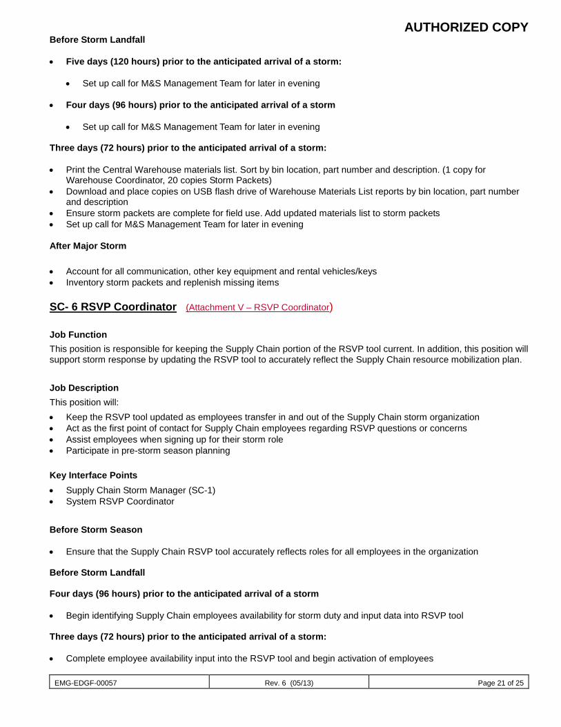
AUTHORIZED COPY
EMG-EDGF-00057 Rev. 6 (05/13) Page 21 of 25
Before Storm Landfall • Five days (120 hours) prior to the anticipated arrival of a storm:
• Set up call for M&S Management Team for later in evening
• Four days (96 hours) prior to the anticipated arrival of a storm
• Set up call for M&S Management Team for later in evening Three days (72 hours) prior to the anticipated arrival of a storm: • Print the Central Warehouse materials list. Sort by bin location, part number and description. (1 copy for
Warehouse Coordinator, 20 copies Storm Packets) • Download and place copies on USB flash drive of Warehouse Materials List reports by bin location, part number
and description • Ensure storm packets are complete for field use. Add updated materials list to storm packets • Set up call for M&S Management Team for later in evening
After Major Storm
• Account for all communication, other key equipment and rental vehicles/keys • Inventory storm packets and replenish missing items SC- 6 RSVP Coordinator (Attachment V – RSVP Coordinator) Job Function This position is responsible for keeping the Supply Chain portion of the RSVP tool current. In addition, this position will support storm response by updating the RSVP tool to accurately reflect the Supply Chain resource mobilization plan. Job Description This position will: • Keep the RSVP tool updated as employees transfer in and out of the Supply Chain storm organization • Act as the first point of contact for Supply Chain employees regarding RSVP questions or concerns • Assist employees when signing up for their storm role • Participate in pre-storm season planning Key Interface Points • Supply Chain Storm Manager (SC-1) • System RSVP Coordinator Before Storm Season • Ensure that the Supply Chain RSVP tool accurately reflects roles for all employees in the organization Before Storm Landfall Four days (96 hours) prior to the anticipated arrival of a storm • Begin identifying Supply Chain employees availability for storm duty and input data into RSVP tool Three days (72 hours) prior to the anticipated arrival of a storm: • Complete employee availability input into the RSVP tool and begin activation of employees

AUTHORIZED COPY
EMG-EDGF-00057 Rev. 6 (05/13) Page 22 of 25
Two days (48 hours) prior to the anticipated arrival of a storm: • Complete activation of all identified employees One day (24 hours) prior to the anticipated arrival of a storm: • Finalize any pre-storm resource allocation plan adjustments in the RSVP tool During Major Storm • Periodically update resource allocation adjustments in the RSVP tool throughout the restoration effort • Release employees from storm support, as they become available, for use by other storm organizations After Major Storm • Release all employees from the current storm in the RSVP tool • Participate in any lessons learned exercises after each storm event • Forward lessons learned results to the System RSVP Coordinator
NOTE: While the Support Services groups listed below are not a part of the Supply Chain M&S Florida organization, Purchasing Support, Technical Support and Financial Support personnel play an integral role at the Supply Chain Storm Center during a major storm. Therefore, a description of their job functions and responsibilities is included.
SS-1 Technical Support (Attachment I - M&S Technical Support) Job Function This position is responsible for ensuring that all Passport related issues are promptly addressed and resolved. Job Duties This position will: • Report to the Supply Chain Storm Coordinator • Initiate actions to promptly resolve all Passport system related issues • Provide technical advice as needed to increase efficiency for the Administrative staff and Materials Handlers while
using the Passport system • Serve as a liaison with the IT Helpdesk to resolve all hardware related issues • Serve as the point of contact for setting up new work stations and special reporting requirements/requests • Provide timely communication of the status of all Passport related issues to Administrative Support staff, Materials
Handlers, Site Procurement Support and the Supply Chain Storm Coordinator Key Interface Points • Supply Chain Storm Coordinator (SC-1) • Warehouse Coordinator (SC-2) • Administrative Support (SC-5) • Purchasing Support
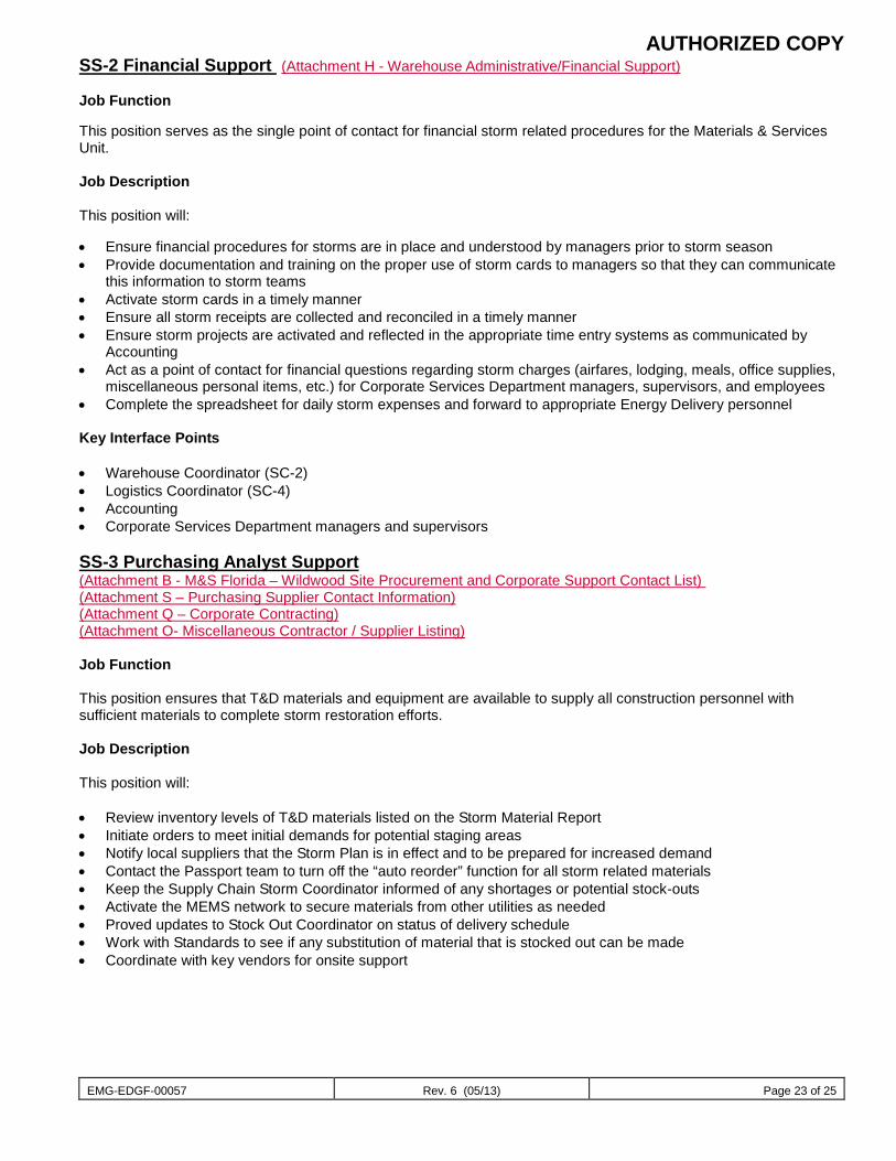
AUTHORIZED COPY
EMG-EDGF-00057 Rev. 6 (05/13) Page 23 of 25
SS-2 Financial Support (Attachment H - Warehouse Administrative/Financial Support) Job Function This position serves as the single point of contact for financial storm related procedures for the Materials & Services Unit. Job Description This position will: • Ensure financial procedures for storms are in place and understood by managers prior to storm season • Provide documentation and training on the proper use of storm cards to managers so that they can communicate
this information to storm teams • Activate storm cards in a timely manner • Ensure all storm receipts are collected and reconciled in a timely manner • Ensure storm projects are activated and reflected in the appropriate time entry systems as communicated by
Accounting • Act as a point of contact for financial questions regarding storm charges (airfares, lodging, meals, office supplies,
miscellaneous personal items, etc.) for Corporate Services Department managers, supervisors, and employees • Complete the spreadsheet for daily storm expenses and forward to appropriate Energy Delivery personnel Key Interface Points • Warehouse Coordinator (SC-2) • Logistics Coordinator (SC-4) • Accounting • Corporate Services Department managers and supervisors SS-3 Purchasing Analyst Support (Attachment B - M&S Florida – Wildwood Site Procurement and Corporate Support Contact List) (Attachment S – Purchasing Supplier Contact Information) (Attachment Q – Corporate Contracting) (Attachment O- Miscellaneous Contractor / Supplier Listing) Job Function This position ensures that T&D materials and equipment are available to supply all construction personnel with sufficient materials to complete storm restoration efforts. Job Description This position will: • Review inventory levels of T&D materials listed on the Storm Material Report • Initiate orders to meet initial demands for potential staging areas • Notify local suppliers that the Storm Plan is in effect and to be prepared for increased demand • Contact the Passport team to turn off the “auto reorder” function for all storm related materials • Keep the Supply Chain Storm Coordinator informed of any shortages or potential stock-outs • Activate the MEMS network to secure materials from other utilities as needed • Proved updates to Stock Out Coordinator on status of delivery schedule • Work with Standards to see if any substitution of material that is stocked out can be made • Coordinate with key vendors for onsite support
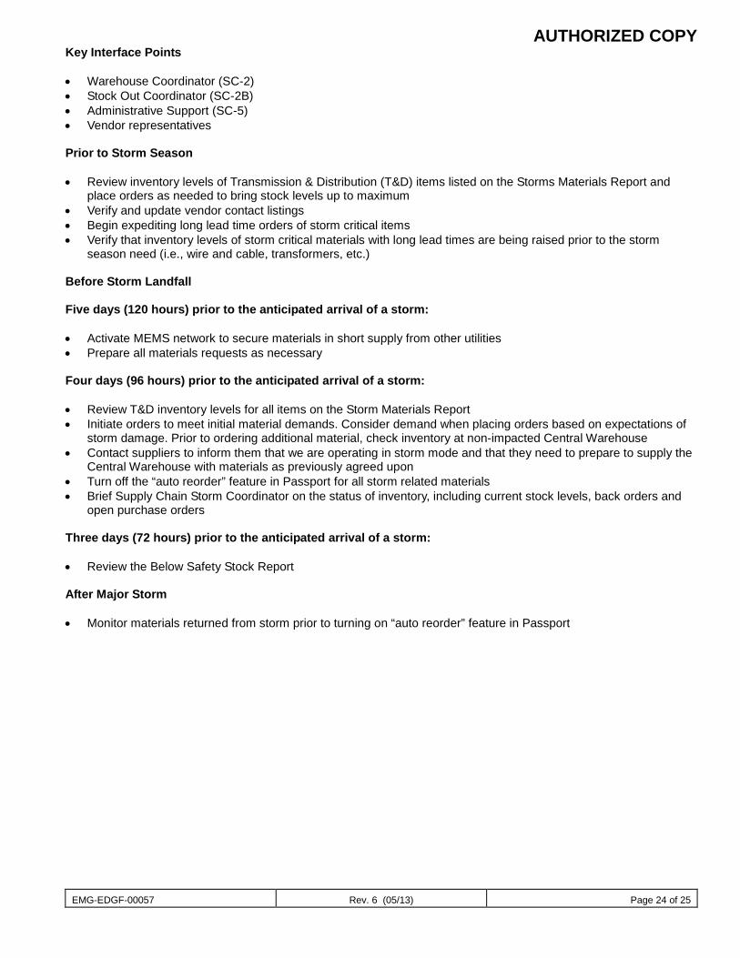
AUTHORIZED COPY
EMG-EDGF-00057 Rev. 6 (05/13) Page 24 of 25
Key Interface Points • Warehouse Coordinator (SC-2) • Stock Out Coordinator (SC-2B) • Administrative Support (SC-5) • Vendor representatives Prior to Storm Season • Review inventory levels of Transmission & Distribution (T&D) items listed on the Storms Materials Report and
place orders as needed to bring stock levels up to maximum • Verify and update vendor contact listings • Begin expediting long lead time orders of storm critical items • Verify that inventory levels of storm critical materials with long lead times are being raised prior to the storm
season need (i.e., wire and cable, transformers, etc.) Before Storm Landfall Five days (120 hours) prior to the anticipated arrival of a storm: • Activate MEMS network to secure materials in short supply from other utilities • Prepare all materials requests as necessary Four days (96 hours) prior to the anticipated arrival of a storm: • Review T&D inventory levels for all items on the Storm Materials Report • Initiate orders to meet initial material demands. Consider demand when placing orders based on expectations of
storm damage. Prior to ordering additional material, check inventory at non-impacted Central Warehouse • Contact suppliers to inform them that we are operating in storm mode and that they need to prepare to supply the
Central Warehouse with materials as previously agreed upon • Turn off the “auto reorder” feature in Passport for all storm related materials • Brief Supply Chain Storm Coordinator on the status of inventory, including current stock levels, back orders and
open purchase orders Three days (72 hours) prior to the anticipated arrival of a storm: • Review the Below Safety Stock Report After Major Storm • Monitor materials returned from storm prior to turning on “auto reorder” feature in Passport
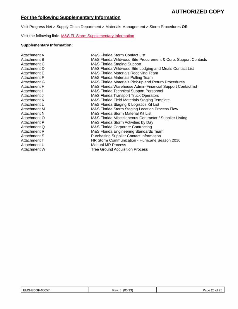
AUTHORIZED COPY
EMG-EDGF-00057 Rev. 6 (05/13) Page 25 of 25
For the following Supplementary Information Visit Progress Net > Supply Chain Department > Materials Management > Storm Procedures OR
Visit the following link: M&S FL Storm Supplementary Information Supplementary Information: Attachment A M&S Florida Storm Contact List Attachment B M&S Florida Wildwood Site Procurement & Corp. Support Contacts Attachment C M&S Florida Staging Support Attachment D M&S Florida Wildwood Site Lodging and Meals Contact List Attachment E M&S Florida Materials Receiving Team Attachment F M&S Florida Materials Pulling Team Attachment G M&S Florida Materials Pick-up and Return Procedures Attachment H M&S Florida Warehouse Admin-Financial Support Contact list Attachment I M&S Florida Technical Support Personnel Attachment J M&S Florida Transport Truck Operators Attachment K M&S Florida Field Materials Staging Template Attachment L M&S Florida Staging & Logistics Kit List Attachment M M&S Florida Storm Staging Location Process Flow Attachment N M&S Florida Storm Material Kit List Attachment O M&S Florida Miscellaneous Contractor / Supplier Listing Attachment P M&S Florida Storm Activities by Day Attachment Q M&S Florida Corporate Contracting Attachment R M&S Florida Engineering Standards Team Attachment S Purchasing Supplier Contact Information Attachment T HR Storm Communication - Hurricane Season 2010 Attachment U Manual MR Process Attachment W Tree Ground Acquisition Process
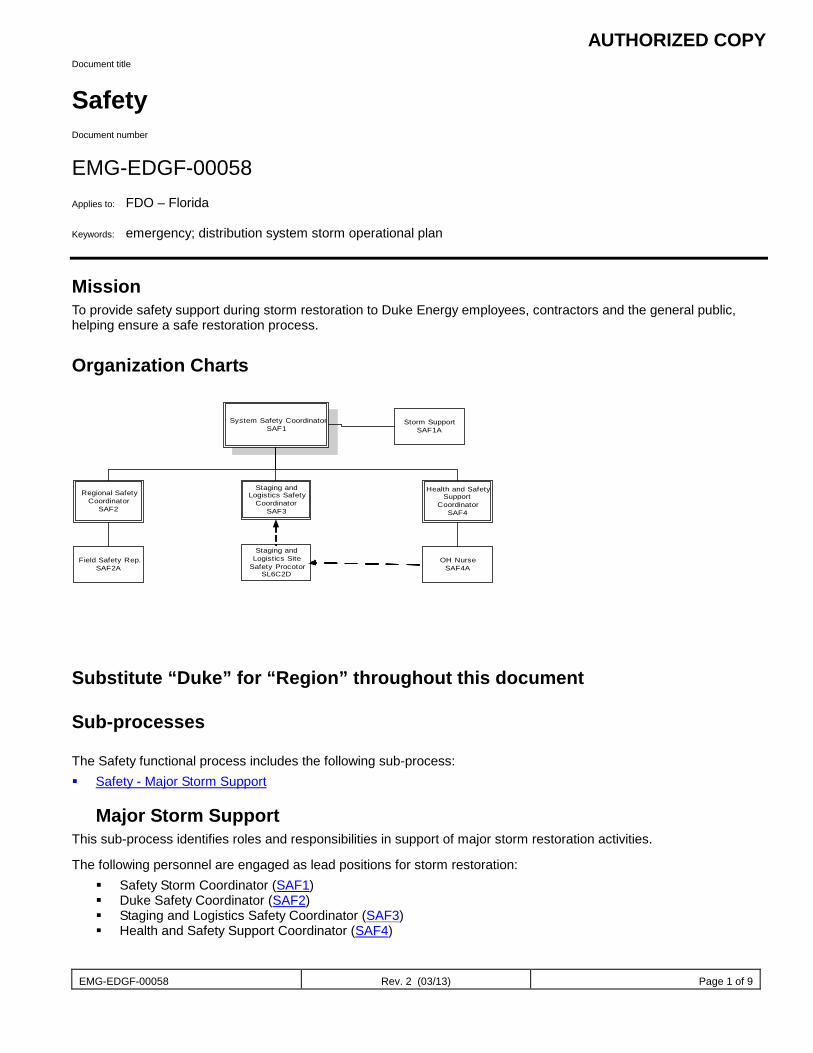
AUTHORIZED COPY
EMG-EDGF-00058 Rev. 2 (03/13) Page 1 of 9
Document title
Safety Document number
EMG-EDGF-00058 Applies to: FDO – Florida Keywords: emergency; distribution system storm operational plan Mission To provide safety support during storm restoration to Duke Energy employees, contractors and the general public, helping ensure a safe restoration process.
Organization Charts
System Safety CoordinatorSAF1
Staging andLogistics Safety
CoordinatorSAF3
Health and SafetySupport
CoordinatorSAF4
Regional SafetyCoordinator
SAF2
Storm SupportSAF1A
OH NurseSAF4A
Staging andLogistics Site
Safety ProcotorSL6C2D
Field Safety Rep.SAF2A
Substitute “Duke” for “Region” throughout this document Sub-processes The Safety functional process includes the following sub-process: Safety - Major Storm Support
Major Storm Support
This sub-process identifies roles and responsibilities in support of major storm restoration activities.
The following personnel are engaged as lead positions for storm restoration: Safety Storm Coordinator (SAF1) Duke Safety Coordinator (SAF2) Staging and Logistics Safety Coordinator (SAF3) Health and Safety Support Coordinator (SAF4)
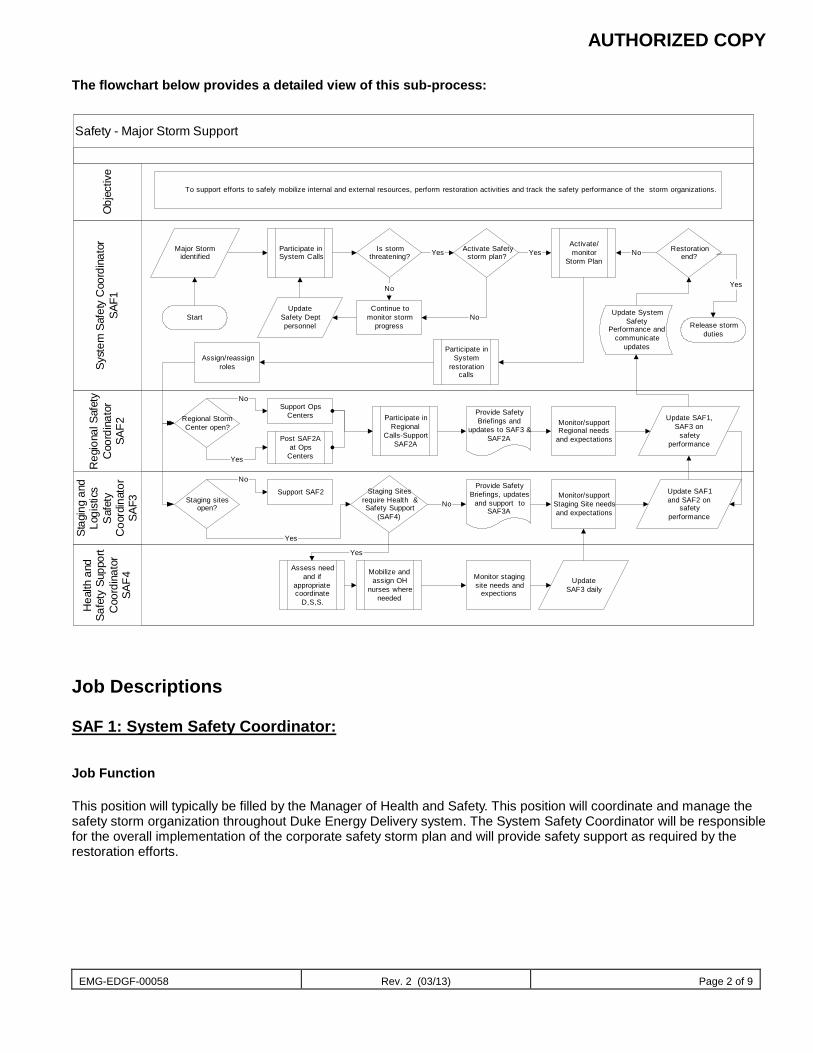
AUTHORIZED COPY
EMG-EDGF-00058 Rev. 2 (03/13) Page 2 of 9
The flowchart below provides a detailed view of this sub-process:
Safety - Major Storm Support
Stag
ing
and
Logi
stic
sS
afet
yC
oord
inat
orSA
F3
Hea
lth a
ndSa
fety
Sup
port
Coo
rdin
ator
SAF4
Syst
em S
afet
y C
oord
inat
orSA
F1
Reg
iona
l Saf
ety
Coo
rdin
ator
SAF2
Obj
ectiv
e
To support efforts to safely mobilize internal and external resources, perform restoration activities and track the safety performance of the storm organizations.
Start
Major Stormidentified
Participate inSystem Calls
Is stormthreatening?
Continue tomonitor storm
progress
UpdateSafety Deptpersonnel
No
Yes Activate Safetystorm plan?
No
Activate/monitor
Storm PlanYes
Assign/reassignroles
Regional StormCenter open?
Staging sitesopen?
Staging Sitesrequire Health &Safety Support
(SAF4)
Support SAF2
No
Yes
Support OpsCenters
No
Post SAF2Aat Ops
CentersYes
Participate inRegional
Calls-SupportSAF2A
Provide SafetyBriefings and
updates to SAF3 &SAF2A
Mobilize andassign OH
nurses whereneeded
Yes
Monitor stagingsite needs and
expections
Provide SafetyBriefings, updates
and support toSAF3A
No
UpdateSAF3 daily
Monitor/supportStaging Site needsand expectations
Monitor/supportRegional needs
and expectations
Update SAF1and SAF2 on
safetyperformance
Update SAF1,SAF3 on
safetyperformance
Restorationend?No
Release stormduties
Yes
Participate inSystem
restorationcalls
Update SystemSafety
Performance andcommunicate
updates
Assess needand if
appropriatecoordinate
D,S,S.
Job Descriptions SAF 1: System Safety Coordinator:
Job Function This position will typically be filled by the Manager of Health and Safety. This position will coordinate and manage the safety storm organization throughout Duke Energy Delivery system. The System Safety Coordinator will be responsible for the overall implementation of the corporate safety storm plan and will provide safety support as required by the restoration efforts.
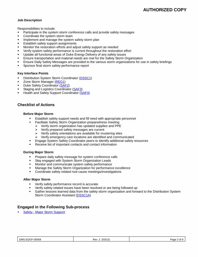
AUTHORIZED COPY
EMG-EDGF-00058 Rev. 2 (03/13) Page 3 of 9
Job Description Responsibilities to include: Participate in the system storm conference calls and provide safety messages Coordinate the system storm team Implement and manage the system safety storm plan Establish safety support assignments Monitor the restoration efforts and adjust safety support as needed Verify system safety performance is current throughout the restoration effort Update all functional areas of Duke Energy Delivery of any safety issues Ensure transportation and material needs are met for the Safety Storm Organization Ensure Daily Safety Messages are provided to the various storm organizations for use in safety briefings Sponsor final storm safety performance report
Key Interface Points Distribution System Storm Coordinator (DSSC1) Zone Storm Manager (REG1) Duke Safety Coordinator (SAF2) Staging and Logistics Coordinator (SAF3) Health and Safety Support Coordinator (SAF4)
Checklist of Actions
Before Major Storm Establish safety support needs and fill need with appropriate personnel Facilitate Safety Storm Organization preparedness meeting
Verify storm organization has updated supplies and PPE Verify prepared safety messages are current Verify safety orientations are available for mustering sites Verify emergency care locations are identified and communicated
Engage System Safety Coordinator peers to identify additional safety resources Receive list of important contacts and contact information
During Major Storm Prepare daily safety message for system conference calls Stay engaged with System Storm Organization Leads Monitor and communicate system safety performance Manage the Safety Storm Organization for performance excellence Coordinate safety related root cause meetings/investigations
After Major Storm Verify safety performance record is accurate Verify safety related issues have been resolved or are being followed up Gather lessons learned data from the safety storm organization and forward to the Distribution System
Storm Coordinator Assistant (DSSC1A)
Engaged in the Following Sub-process Safety - Major Storm Support
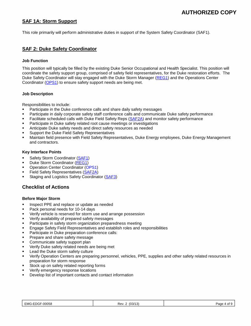
AUTHORIZED COPY
EMG-EDGF-00058 Rev. 2 (03/13) Page 4 of 9
SAF 1A: Storm Support This role primarily will perform administrative duties in support of the System Safety Coordinator (SAF1).
SAF 2: Duke Safety Coordinator
Job Function
This position will typically be filled by the existing Duke Senior Occupational and Health Specialist. This position will coordinate the safety support group, comprised of safety field representatives, for the Duke restoration efforts. The Duke Safety Coordinator will stay engaged with the Duke Storm Manager (REG1) and the Operations Center Coordinator (OPS1) to ensure safety support needs are being met.
Job Description Responsibilities to include: Participate in the Duke conference calls and share daily safety messages Participate in daily corporate safety staff conference calls and communicate Duke safety performance Facilitate scheduled calls with Duke Field Safety Reps (SAF2A) and monitor safety performance Participate in Duke safety related root cause meetings or investigations Anticipate Duke safety needs and direct safety resources as needed Support the Duke Field Safety Representatives Maintain field presence with Field Safety Representatives, Duke Energy employees, Duke Energy Management
and contractors.
Key Interface Points Safety Storm Coordinator (SAF1) Duke Storm Coordinator (REG1) Operation Center Coordinator (OPS1) Field Safety Representatives (SAF2A) Staging and Logistics Safety Coordinator (SAF3)
Checklist of Actions
Before Major Storm Inspect PPE and replace or update as needed Pack personal needs for 10-14 days Verify vehicle is reserved for storm use and arrange possession Verify availability of prepared safety messages Participate in safety storm organization preparedness meeting Engage Safety Field Representatives and establish roles and responsibilities Participate in Duke preparation conference calls: Prepare and share safety message Communicate safety support plan Verify Duke safety related needs are being met Lead the Duke storm safety culture Verify Operation Centers are preparing personnel, vehicles, PPE, supplies and other safety related resources in
preparation for storm response Stock up on safety related reporting forms Verify emergency response locations Develop list of important contacts and contact information
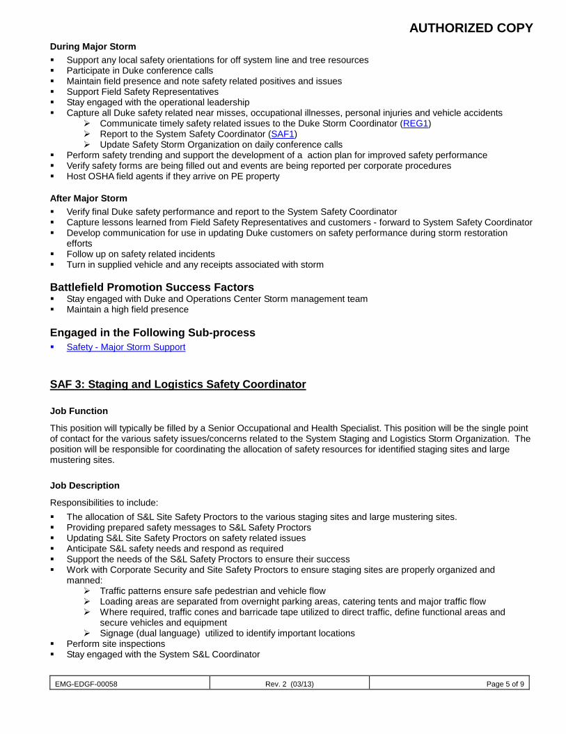
AUTHORIZED COPY
EMG-EDGF-00058 Rev. 2 (03/13) Page 5 of 9
During Major Storm Support any local safety orientations for off system line and tree resources Participate in Duke conference calls Maintain field presence and note safety related positives and issues Support Field Safety Representatives Stay engaged with the operational leadership Capture all Duke safety related near misses, occupational illnesses, personal injuries and vehicle accidents
Communicate timely safety related issues to the Duke Storm Coordinator (REG1) Report to the System Safety Coordinator (SAF1) Update Safety Storm Organization on daily conference calls
Perform safety trending and support the development of a action plan for improved safety performance Verify safety forms are being filled out and events are being reported per corporate procedures Host OSHA field agents if they arrive on PE property
After Major Storm Verify final Duke safety performance and report to the System Safety Coordinator Capture lessons learned from Field Safety Representatives and customers - forward to System Safety Coordinator Develop communication for use in updating Duke customers on safety performance during storm restoration
efforts Follow up on safety related incidents Turn in supplied vehicle and any receipts associated with storm Battlefield Promotion Success Factors Stay engaged with Duke and Operations Center Storm management team Maintain a high field presence
Engaged in the Following Sub-process Safety - Major Storm Support
SAF 3: Staging and Logistics Safety Coordinator
Job Function
This position will typically be filled by a Senior Occupational and Health Specialist. This position will be the single point of contact for the various safety issues/concerns related to the System Staging and Logistics Storm Organization. The position will be responsible for coordinating the allocation of safety resources for identified staging sites and large mustering sites.
Job Description
Responsibilities to include: The allocation of S&L Site Safety Proctors to the various staging sites and large mustering sites. Providing prepared safety messages to S&L Safety Proctors Updating S&L Site Safety Proctors on safety related issues Anticipate S&L safety needs and respond as required Support the needs of the S&L Safety Proctors to ensure their success Work with Corporate Security and Site Safety Proctors to ensure staging sites are properly organized and
manned: Traffic patterns ensure safe pedestrian and vehicle flow Loading areas are separated from overnight parking areas, catering tents and major traffic flow Where required, traffic cones and barricade tape utilized to direct traffic, define functional areas and
secure vehicles and equipment Signage (dual language) utilized to identify important locations
Perform site inspections Stay engaged with the System S&L Coordinator
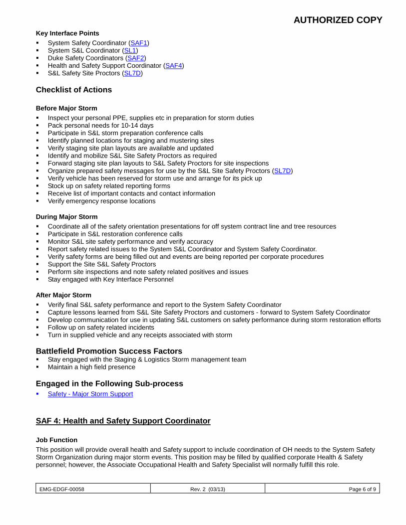
AUTHORIZED COPY
EMG-EDGF-00058 Rev. 2 (03/13) Page 6 of 9
Key Interface Points System Safety Coordinator (SAF1) System S&L Coordinator (SL1) Duke Safety Coordinators (SAF2) Health and Safety Support Coordinator (SAF4) S&L Safety Site Proctors (SL7D)
Checklist of Actions
Before Major Storm Inspect your personal PPE, supplies etc in preparation for storm duties Pack personal needs for 10-14 days Participate in S&L storm preparation conference calls Identify planned locations for staging and mustering sites Verify staging site plan layouts are available and updated Identify and mobilize S&L Site Safety Proctors as required Forward staging site plan layouts to S&L Safety Proctors for site inspections Organize prepared safety messages for use by the S&L Site Safety Proctors (SL7D) Verify vehicle has been reserved for storm use and arrange for its pick up Stock up on safety related reporting forms Receive list of important contacts and contact information Verify emergency response locations
During Major Storm Coordinate all of the safety orientation presentations for off system contract line and tree resources Participate in S&L restoration conference calls Monitor S&L site safety performance and verify accuracy Report safety related issues to the System S&L Coordinator and System Safety Coordinator. Verify safety forms are being filled out and events are being reported per corporate procedures Support the Site S&L Safety Proctors Perform site inspections and note safety related positives and issues Stay engaged with Key Interface Personnel
After Major Storm Verify final S&L safety performance and report to the System Safety Coordinator Capture lessons learned from S&L Site Safety Proctors and customers - forward to System Safety Coordinator Develop communication for use in updating S&L customers on safety performance during storm restoration efforts Follow up on safety related incidents Turn in supplied vehicle and any receipts associated with storm Battlefield Promotion Success Factors Stay engaged with the Staging & Logistics Storm management team Maintain a high field presence
Engaged in the Following Sub-process Safety - Major Storm Support
SAF 4: Health and Safety Support Coordinator
Job Function This position will provide overall health and Safety support to include coordination of OH needs to the System Safety Storm Organization during major storm events. This position may be filled by qualified corporate Health & Safety personnel; however, the Associate Occupational Health and Safety Specialist will normally fulfill this role.
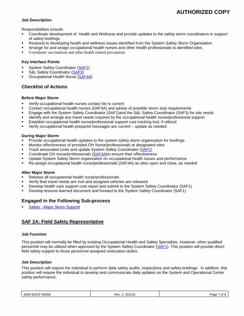
AUTHORIZED COPY
EMG-EDGF-00058 Rev. 2 (03/13) Page 7 of 9
Job Description Responsibilities include: Coordinate development of Health and Wellness and provide updates to the safety storm coordinators in support
of safety briefings Respond to developing health and wellness issues identified from the System Safety Storm Organization Arrange for and assign occupational health nurses and other health professionals to identified sites Coordinate vaccinations and other health related precautions
Key Interface Points System Safety Coordinator (SAF1) S&L Safety Coordinator (SAF3) Occupational Health Nurse (SAF4A)
Checklist of Actions
Before Major Storm Verify occupational health nurses contact list is current Contact occupational health nurses (SAF4A) and advise of possible storm duty requirements Engage with the System Safety Coordinator (SAF1)and the S&L Safety Coordinator (SAF3) for site needs Identify and arrange any travel needs required by the occupational health nurse/professional support Establish occupational health nurse/professional support cost tracking tool, if utilized Verify occupational health prepared messages are current – update as needed During Major Storm Provide occupational health updates to the system safety storm organization for breifings Monitor effectiveness of provided OH Nurse/professionals at designated sites Track associated costs and update System Safety Coordinator (SAF1) Coordinate OH nurse/professionals (SAF4A)to ensure their effectiveness Update System Safety Storm organization on occupational health issues and performance Re-assign occupational health nurse/professionals (SAF4A) as sites open and close, as needed After Major Storm Release all occupational health nurse/professionals Verify final travel needs are met and assigned vehicles are released Develop health care support cost report and submit to the System Safety Coordinator (SAF1) Develop lessons learned document and forward to the System Safety Coordinator (SAF1)
Engaged in the Following Sub-process Safety - Major Storm Support
SAF 2A: Field Safety Representative Job Function
This position will normally be filled by existing Occupational Health and Safety Specialists. However, other qualified personnel may be utilized when approved by the System Safety Coordinator (SAF1). This position will provide direct field safety support to those personnel assigned restoration duties.
Job Description This position will require the individual to perform daily safety audits, inspections and safety briefings. In addition, this position will require the individual to develop and communicate daily updates on the System and Operational Center safety performance.
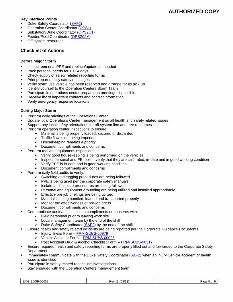
AUTHORIZED COPY
EMG-EDGF-00058 Rev. 2 (03/13) Page 8 of 9
Key Interface Points Duke Safety Coordinator (SAF2) Operation Center Coordinator (OPS1) Substation/Duke Coordinator (OPS2C1) Feeder/Field Coordinator (OPS2C1A) Off system resources
Checklist of Actions
Before Major Storm Inspect personal PPE and replace/update as needed Pack personal needs for 10-14 days Check supply of safety related reporting forms Print prepared daily safety messages Verify storm use vehicle has been reserved and arrange for its pick up Identify yourself to the Operation Centers Storm Team Participate in operations center preparation meetings, if possible. Receive list of important contacts and contact information Verify emergency response locations
During Major Storm Perform daily briefings at the Operations Center Update local Operations Center management on all health and safety related issues Support any local safety orientations for off system line and tree resources Perform operation center inspections to ensure:
Material is being properly loaded, secured or discarded Traffic flow is not being impeded Housekeeping remains a priority Document compliments and concerns
Perform tool and equipment inspections: Verify good housekeeping is being performed on the vehicles Inspect personal and PE tools – verify that they are calibrated, in-date and in good working condition Verify PPE is in-date and in good working condition Document compliments and concerns
Perform daily field audits to verify: Switching and tagging procedures are being followed PPE is being used per the corporate safety manuals Isolate and insulate procedures are being followed Personal and equipment grounding are being utilized and installed appropriately Effective pre job briefings are being utilized Material is being handled, loaded and transported properly Monitor the effectiveness of pre-job briefs Document compliments and concerns
Communicate audit and inspection compliments or concerns with: Field personnel prior to leaving work site Local management team by the end of the shift Duke Safety Coordinator (SAF2) by the end of the shift
Ensure health and safety related incidents are being reported per the Corporate Guidance Documents Injury/Illness Form – FRM-SUBS-00979 Vehicle Accident Form – FRM-SUBS-00025 Post Accident Drug & Alcohol Checklist Form – FRM-SUBS-00317
Ensure required health and safety reporting forms are properly filled out and forwarded to the Corporate Safety Department
Immediately communicate with the Duke Safety Coordinator (SAF2) when an injury, vehicle accident or health issue is identified
Participate in safety related root cause investigations Stay engaged with the Operation Centers management team
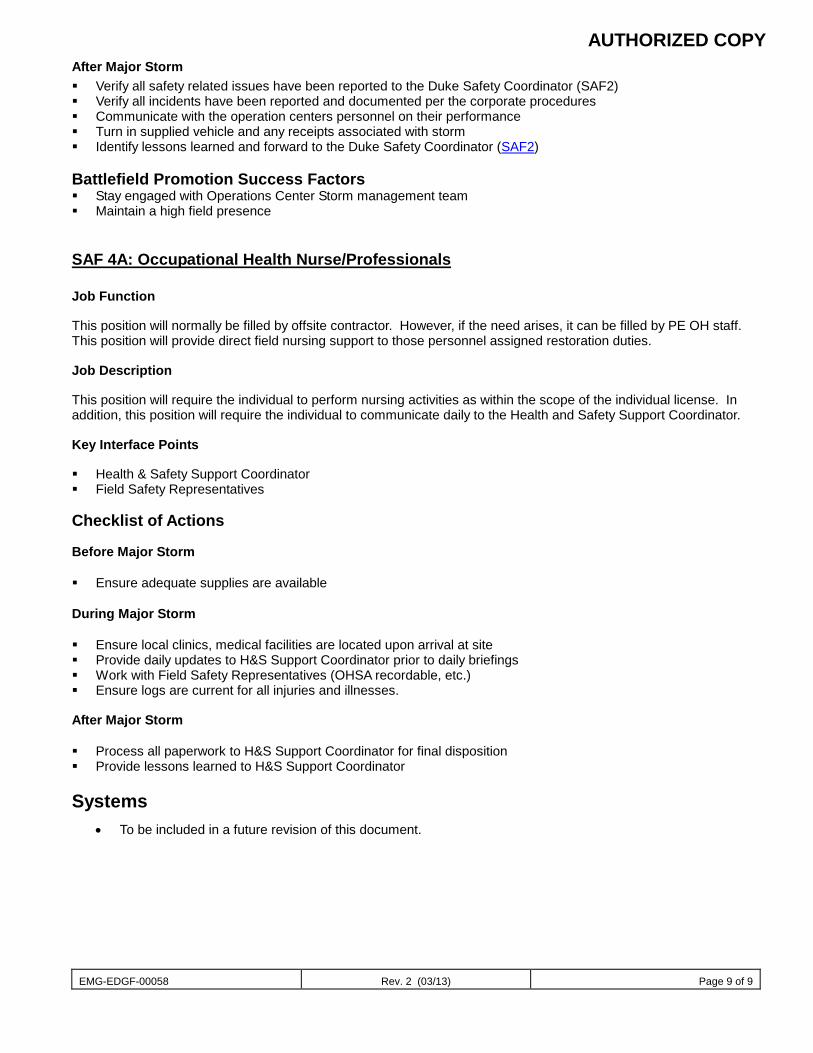
AUTHORIZED COPY
EMG-EDGF-00058 Rev. 2 (03/13) Page 9 of 9
After Major Storm Verify all safety related issues have been reported to the Duke Safety Coordinator (SAF2) Verify all incidents have been reported and documented per the corporate procedures Communicate with the operation centers personnel on their performance Turn in supplied vehicle and any receipts associated with storm Identify lessons learned and forward to the Duke Safety Coordinator (SAF2) Battlefield Promotion Success Factors Stay engaged with Operations Center Storm management team Maintain a high field presence
SAF 4A: Occupational Health Nurse/Professionals Job Function This position will normally be filled by offsite contractor. However, if the need arises, it can be filled by PE OH staff. This position will provide direct field nursing support to those personnel assigned restoration duties. Job Description This position will require the individual to perform nursing activities as within the scope of the individual license. In addition, this position will require the individual to communicate daily to the Health and Safety Support Coordinator. Key Interface Points Health & Safety Support Coordinator Field Safety Representatives
Checklist of Actions Before Major Storm Ensure adequate supplies are available During Major Storm Ensure local clinics, medical facilities are located upon arrival at site Provide daily updates to H&S Support Coordinator prior to daily briefings Work with Field Safety Representatives (OHSA recordable, etc.) Ensure logs are current for all injuries and illnesses. After Major Storm Process all paperwork to H&S Support Coordinator for final disposition Provide lessons learned to H&S Support Coordinator
Systems • To be included in a future revision of this document.
EMG-EDGF-00059 Rev. 1 (03/13) Page 1 of 21
Document
Human Resources Document number
EMG-EDGF-00059 Applies to: FDO – Florida Keywords: emergency; distribution system storm operational plan
Table of Contents
Mission…………………………………………………………………………………….2 Guiding Principals and Objectives ...................................................................................... 2 HR Storm Team Org Chart .................................................................................................. 3 HR Storm Team Conference Call Schedule and Agenda .................................................... 4 Communication Plan ........................................................................................................... 5 Roles and Responsibilities
HR Storm Manager ........................................................................................................ 6 HR System Storm Coordinator ...................................................................................... 7 HR RSVP Coordinator ................................................................................................... 8 HR Field Support Specialist........................................................................................... 9 HR Storm Coordinator: ESC ....................................................................................... 10 HR Storm Specialist: ESC ........................................................................................... 11 Compensation Expert ................................................................................................... 12 Compensation Specialist .............................................................................................. 13 Employee Tracking Coordinator .................................................................................. 14 Employee Tracking Specialist ...................................................................................... 15 Employee Needs Coordinator ...................................................................................... 16 Employee Needs Specialist .......................................................................................... 17 Medical Benefits Coordinator ...................................................................................... 18 Medical Benefits Specialist .......................................................................................... 19 Labor Relations Expert ................................................................................................ 20 Labor Relations Specialist ........................................................................................... 21

EMG-EDGF-00059 Rev. 1 (03/13) Page 2 of 21
Mission The Human Resources Department (HR) provides employee support and services; human resource information systems support (HRIS), policy development and administration to the entire company. It is imperative that HR employees provide service and support continuity during storm conditions and that people, procedures and systems are in place to manage the necessary employee support, policy administration, and issue resolution during these critical periods. All departments within the company have developed storm plans which have identified specific needs and roles in the event of major storms. Likewise, this Storm Plan has been created to guide the HR team in preparing for and providing support to our customers during storm conditions.
Guiding Principals and Objectives
• Corp Communications will communicate in advance of any approaching storm that the Company has an expectation for all employees to have a personal evacuation plan for themselves and their families such that they can sustain themselves for up to 5 days without services or assistance from the government or the company. Employees should utilize shelters and resources provided by local, state and national government.
• Primary HR support will be provided by the designated HR Representative for that employee and organization to the extent that
they are available. Otherwise, HR support will be provided by Carolina HR for Florida based storms. And, if necessary, reciprocal support will be provided by Florida HR in St Pete.
• There will be an HR Storm Organization that will meet daily by phone or in person in the days preceding and following a storm
to provide guidance regarding policies and programs as necessary. In general, the Company will leverage all existing policies and programs that are currently in existence. If circumstances warrant, the HR Storm Organization will propose additional policies or programs.
• In the event of a catastrophic storm, HR will initiate the Company’s Employee Tracking Processes and will notify employees of
the process and the need for the process. • All HR employees are expected to make every effort to be available to assist with storm recovery by responding to their RSVP
Coordinator if called upon.
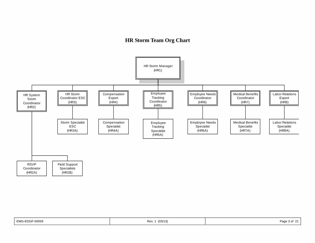
EMG-EDGF-00059 Rev. 1 (03/13) Page 3 of 21
HR Storm Team Org Chart
HR Storm Manager(HR1)
CompensationExpert(HR4)
EmployeeTracking
Coordinator(HR5)
HR StormCoordinator ESC
(HR3)
Medical BenefitsCoordinator
(HR7)
Employee NeedsCoordinator
(HR6)
HR SystemStorm
Coordinator(HR2)
Labor RelationsExpert(HR8)
RSVPCoordinator
(HR2A)
Field SupportSpecialists
(HR2B)
Storm SpecialistESC
(HR3A)
CompensationSpecialist(HR4A)
EmployeeTrackingSpecialist(HR5A)
Employee NeedsSpecialist(HR6A)
Medical BenefitsSpecialist(HR7A)
Labor RelationsSpecialist(HR8A)
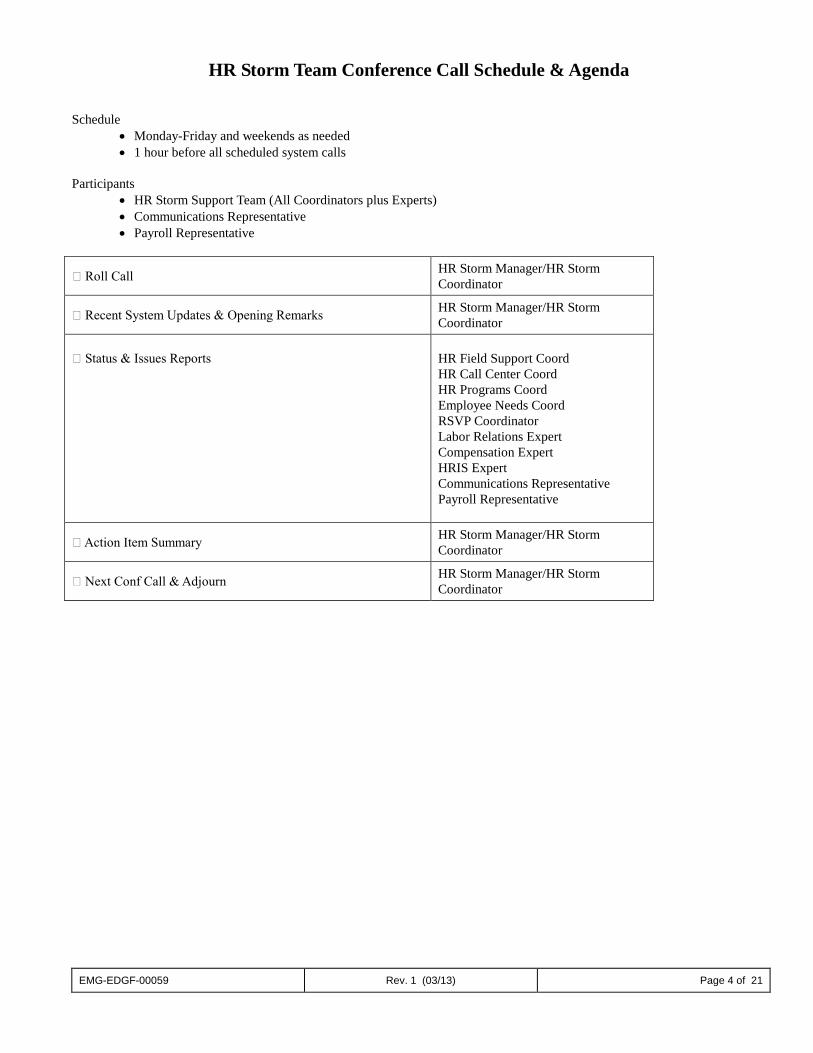
EMG-EDGF-00059 Rev. 1 (03/13) Page 4 of 21
HR Storm Team Conference Call Schedule & Agenda
Schedule • Monday-Friday and weekends as needed • 1 hour before all scheduled system calls
Participants
• HR Storm Support Team (All Coordinators plus Experts) • Communications Representative • Payroll Representative
Roll Call HR Storm Manager/HR Storm Coordinator
Recent System Updates & Opening Remarks HR Storm Manager/HR Storm Coordinator
Status & Issues Reports
HR Field Support Coord HR Call Center Coord HR Programs Coord Employee Needs Coord RSVP Coordinator Labor Relations Expert Compensation Expert HRIS Expert Communications Representative Payroll Representative
Action Item Summary HR Storm Manager/HR Storm Coordinator
Next Conf Call & Adjourn HR Storm Manager/HR Storm Coordinator
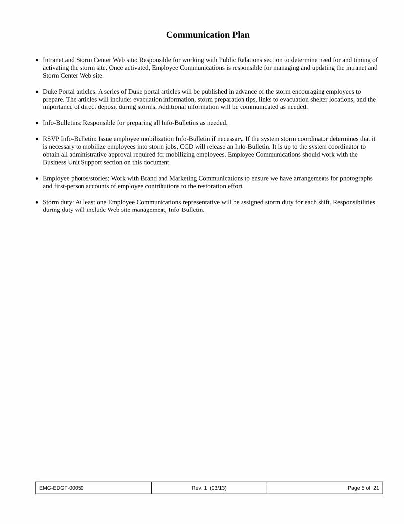
EMG-EDGF-00059 Rev. 1 (03/13) Page 5 of 21
Communication Plan • Intranet and Storm Center Web site: Responsible for working with Public Relations section to determine need for and timing of
activating the storm site. Once activated, Employee Communications is responsible for managing and updating the intranet and Storm Center Web site.
• Duke Portal articles: A series of Duke portal articles will be published in advance of the storm encouraging employees to
prepare. The articles will include: evacuation information, storm preparation tips, links to evacuation shelter locations, and the importance of direct deposit during storms. Additional information will be communicated as needed.
• Info-Bulletins: Responsible for preparing all Info-Bulletins as needed. • RSVP Info-Bulletin: Issue employee mobilization Info-Bulletin if necessary. If the system storm coordinator determines that it
is necessary to mobilize employees into storm jobs, CCD will release an Info-Bulletin. It is up to the system coordinator to obtain all administrative approval required for mobilizing employees. Employee Communications should work with the Business Unit Support section on this document.
• Employee photos/stories: Work with Brand and Marketing Communications to ensure we have arrangements for photographs
and first-person accounts of employee contributions to the restoration effort. • Storm duty: At least one Employee Communications representative will be assigned storm duty for each shift. Responsibilities
during duty will include Web site management, Info-Bulletin.

EMG-EDGF-00059 Rev. 1 (03/13) Page 6 of 21
Job Descriptions HR1: HR Storm Manager Job Function The HR Storm Manager serves as a liaison to corporate HR and leads the HR support function including system level support, field support, HR policy development, interpretation and HR related communications during major storms. Job Description • Participates in HR storm meetings/calls as necessary. • Identifies and fills HR storm roles. • Prompt VP-HR to communicate to HR employees the expectation to assist in storm preparation efforts via their storm role. • Assign HR personnel to provide backup support to HR Storm Manager, HR System Storm Coordinator and HR Field Support
Specialist(s) as needed. • Assist in developing storm specific HR policies/programs, as needed. • Review and approve all HR related employee communications and coordinate publication of such with Corporate
Communications. • Develops and oversees storm checklist, such as:
o Pre-Storm Drill and Communications o Two-Day Employee Preparation Activities (homes/families) o HR Storm Meetings/Call Schedule
• Provides direction to HR Coordinator Storm Roles • Oversees storm specific policy development and application related to compensation & other work related issues. Assigns specialist to assist with duties as needed. Key Interface Points • HR Storm Team • Corporate Services (Real Estate) • Corporate Communications • Business Services Training Requirements This role is filled by experienced HR Managers or HR Specialists and therefore reserved for those with human resources generalist experience. As such, there are no training requirements for performing this role during storms.
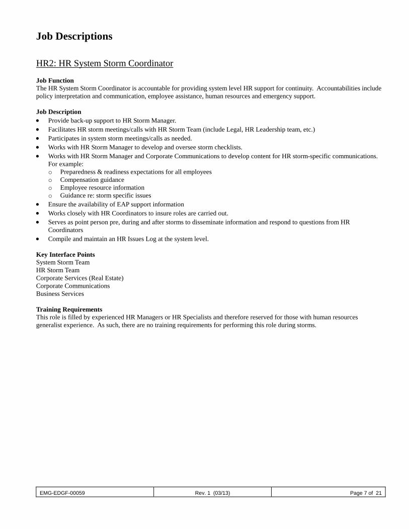
EMG-EDGF-00059 Rev. 1 (03/13) Page 7 of 21
Job Descriptions HR2: HR System Storm Coordinator Job Function The HR System Storm Coordinator is accountable for providing system level HR support for continuity. Accountabilities include policy interpretation and communication, employee assistance, human resources and emergency support. Job Description • Provide back-up support to HR Storm Manager. • Facilitates HR storm meetings/calls with HR Storm Team (include Legal, HR Leadership team, etc.) • Participates in system storm meetings/calls as needed. • Works with HR Storm Manager to develop and oversee storm checklists. • Works with HR Storm Manager and Corporate Communications to develop content for HR storm-specific communications.
For example: o Preparedness & readiness expectations for all employees o Compensation guidance o Employee resource information o Guidance re: storm specific issues
• Ensure the availability of EAP support information • Works closely with HR Coordinators to insure roles are carried out. • Serves as point person pre, during and after storms to disseminate information and respond to questions from HR
Coordinators • Compile and maintain an HR Issues Log at the system level. Key Interface Points System Storm Team HR Storm Team Corporate Services (Real Estate) Corporate Communications Business Services Training Requirements This role is filled by experienced HR Managers or HR Specialists and therefore reserved for those with human resources generalist experience. As such, there are no training requirements for performing this role during storms.
EMG-EDGF-00059 Rev. 1 (03/13) Page 8 of 21
Job Descriptions HR2A: HR RSVP Coordinator Job Function The function of the HR RSVP Coordinator is to insure each HR employee is assigned a storm role and to assist in activating and monitoring storm roles as applicable. Job Description • Participates in storm calls • Contacts employees new to HR and apprises them of how to sign up for a storm role. • Maintains a current list of storm roles and adjusts as necessary in the event of job changes. • Under the direction of the HR Storm Manager or HR Storm Coordinator, activates the RSVP system during storm activity. • Other duties as assigned Key Interface Points • HR Storm Manager (HR1) • HR System Storm Coordinator (HR2) • Corporate Communications Training Requirements This role is filled by experienced HR Managers or HR Specialists and therefore reserved for those with human resources generalist experience. As such, there are no training requirements for performing this role during storms.
EMG-EDGF-00059 Rev. 1 (03/13) Page 9 of 21
Job Descriptions HR2B: Field Support Specialists Job Function The HR Storm Specialist: The Field Support Specialist is accountable for providing regional and/or local HR support during major storms. Accountabilities include policy interpretation and communication, employee assistance, human resources and emergency support. Job Description • Participates in HR Storm meetings/calls • Provides back-up support to HR System Storm Coordinator and HR Storm Manager • Direct employees to website or other appropriate forums for storm specific policies • Respond to questions requiring policy interpretation • Compile and maintain HR issues log for respective Region and report issues to HR Storm Manager or HR System Storm
Coordinator, whichever is applicable Key Interface Points • HR Storm Manager (HR1) • HR System Storm Coordinator (HR2) Training Requirements This role is filled by experienced HR Managers or HR Specialists and therefore reserved for those with human resources generalist experience. As such, there are no training requirements for performing this role during storms.
EMG-EDGF-00059 Rev. 1 (03/13) Page 10 of 21
Job Descriptions HR3: HR Storm Coordinator: ESC Job Function To receive and disseminate information updates to ESC staff and HR Field Specialists relative to policy and procedure interpretations, and other key communications. Job Description • Participates in HR Storm meetings/calls • Staffs call center with HR personnel • Keeps call center staff informed of policy and procedures Assigns Specialist to assist with duties as needed Key Interface Points • HR Storm Manager (HR1) • HR System Storm Coordinator (HR2) • Corporate Communications Training Requirements This role is filled by experienced HR Managers or HR Specialists and therefore reserved for those with human resources generalist experience. As such, there are no training requirements for performing this role during storms.
EMG-EDGF-00059 Rev. 1 (03/13) Page 11 of 21
Job Descriptions HR3A: HR Storm Specialist: ESC Job Function The HR Storm Specialist: ESC, provides back up support to the HR Storm Coordinator: ESC, and serves to remedy gaps and satisfy unassigned needs. Job Description • Attends HR storm meetings as necessary. • Answers calls from employees, provides guidance, directions and otherwise responds accordingly. • Other duties outlined by the HR Storm Coordinator: ESC, on an as needed basis. Key Interface Points • ESC Storm Coordinator (HR4) • HR System Storm Coordinator (HR2) Training Requirements Training and information will be provided by the ESC Coordinator and the HR System Storm Coordinator.
EMG-EDGF-00059 Rev. 1 (03/13) Page 12 of 21
Job Descriptions HR4: Compensation Expert Job Function The HR Storm Coordinator: Compensation is accountable for designing and implementing pay practices relative to specific storm circumstances, if applicable. Job Description • Participates in HR Storm meetings/calls • Develops storm specific pay policies, including salary continuation, as needed. • Develops storm specific incentive pay recommendations, as needed. • Assigns Specialist to assist with duties as needed. Key Interface Points • HR Storm Manager (HR1) • HR System Storm Coordinator (HR2) • Payroll Training Requirements This role is filled by experienced HR Managers or HR Specialists and therefore reserved for those with human resources generalist experience. As such, there are no training requirements for performing this role during storms.
EMG-EDGF-00059 Rev. 1 (03/13) Page 13 of 21
Job Descriptions HR4A: Compensation Specialist Job Function The HR Storm Specialist provides back up support to the Coordinator: Compensation, and serves to remedy gaps and satisfy unassigned needs. Job Description Other duties outlined by the HR Storm Coordinator, Compensation, on an as needed basis. Key Interface Points • HR Compensation Coordinator (HR4) • HR Storm System Coordinator (HR2) Training Requirements Training and information will be provided by the Compensation Specialist and the HR System Storm Coordinator.
EMG-EDGF-00059 Rev. 1 (03/13) Page 14 of 21
Job Descriptions HR5: Employee Tracking Coordinator (This role will only be activated for catastrophic events) Job Function The Employee Tracking Coordinator leads the development of and coordinates interface with employee tracking systems. Job Description • Participates in HR Storm meetings/calls • Oversees the process/system for tracking employee whereabouts • Provides directions to employees before storm as to how to report their whereabouts, well being, contact information and their
availability to work • Communicates information gathered to the HR Storm Manager, HR System Storm Coordinator, Business Unit Coordinators
and RSVP System Storm Coordinator, as necessary Assigns Specialist to assist with duties as needed. Key Interface Points • HR Storm Manager (HR1) • HR System Storm Coordinator (HR2) Training Requirements This role is filled by experienced HR Managers or HR Specialists and therefore reserved for those with human resources generalist experience. As such, there are no training requirements for performing this role during storms.
EMG-EDGF-00059 Rev. 1 (03/13) Page 15 of 21
Job Descriptions HR 5A: Employee Tracking Specialist (This role will only be activated for catastrophic events) Job Function The Employee Tracking Specialist provides back up support to the Employee Tracking Coordinator, and serves to remedy gaps and satisfy unassigned needs. Job Description Other duties outlined by the Employee Tracking Coordinator on an as needed basis. Key Interface Points • Employee Tracking Coordinator (HR5) Training Requirements Training and information will be provided by the Employee Tracking Coordinator and the HR System Storm Coordinator.
EMG-EDGF-00059 Rev. 1 (03/13) Page 16 of 21
Job Descriptions HR6: Employee Needs Coordinator Job Function The Employee Needs Coordinator is accountable for coordinating the company response to individual’s needs that may be impacted by a major storm. In addition, this position is responsible for the development & implementation of financial support programs for employees impacted by a major storm. Job Description • Participates in HR Storm meetings/calls • Develop process for assuring the availability of EAP counselors for pre/post briefings. • Oversees and maintains financial assistance programs for employees Assigns Specialist to assist with duties as needed. Key Interface Points • HR Storm Manager (HR1) • HR system Support Specialist (HR2) • Payroll Training Requirements This role is filled by experienced HR Managers or HR Specialists and therefore reserved for those with human resources generalist experience. As such, there are no training requirements for performing this role during storms.
EMG-EDGF-00059 Rev. 1 (03/13) Page 17 of 21
Job Descriptions HR6A: Employee Needs Specialist Job Function The Employee Needs Specialist provides back up support to the Employee Needs Coordinator and serves to remedy gaps and satisfy unassigned needs. Job Description Other duties outlined by the Employee Needs Coordinator, on an as needed basis. Key Interface Points • Employee Needs Coordinator (HR6) • HR System Storm Coordinator (HR2) Training Requirements Training and information will be provided by the Employee Needs Coordinator and the HR System Storm Coordinator.
EMG-EDGF-00059 Rev. 1 (03/13) Page 18 of 21
Job Descriptions HR7: Medical Benefits Coordinator: Job Function The Medical Benefits Coordinator is responsible for overseeing & setting company direction regarding issues related to medical benefits. Job Description • Participates in HR Storm meetings/calls • Negotiates with providers for emergency out of network needs. Assigns Specialist to assist with duties as needed. Key Interface Points • HR Manager (HR1) • HR Storm System Coordinator (HR2) Training Requirements This role is filled by experienced HR Managers or HR Specialists and therefore reserved for those with human resources generalist experience. As such, there are no training requirements for performing this role during storms.
EMG-EDGF-00059 Rev. 1 (03/13) Page 19 of 21
Job Descriptions HR7A: Medical Benefits Specialist: Job Function The Medical Benefits Specialist: provides back up support to the Medical Benefits Coordinator and serves to remedy gaps and satisfy unassigned needs. Job Description Other duties outlined by the Medical Benefits Coordinator on an as needed basis. Key Interface Points
• Medical Benefits Coordinator (HR7) • HR Storm System Coordinator (HR2)
Training Requirements Training and information to be provided by the Health and Welfare Coordinator and the HR System Storm Coordinator.
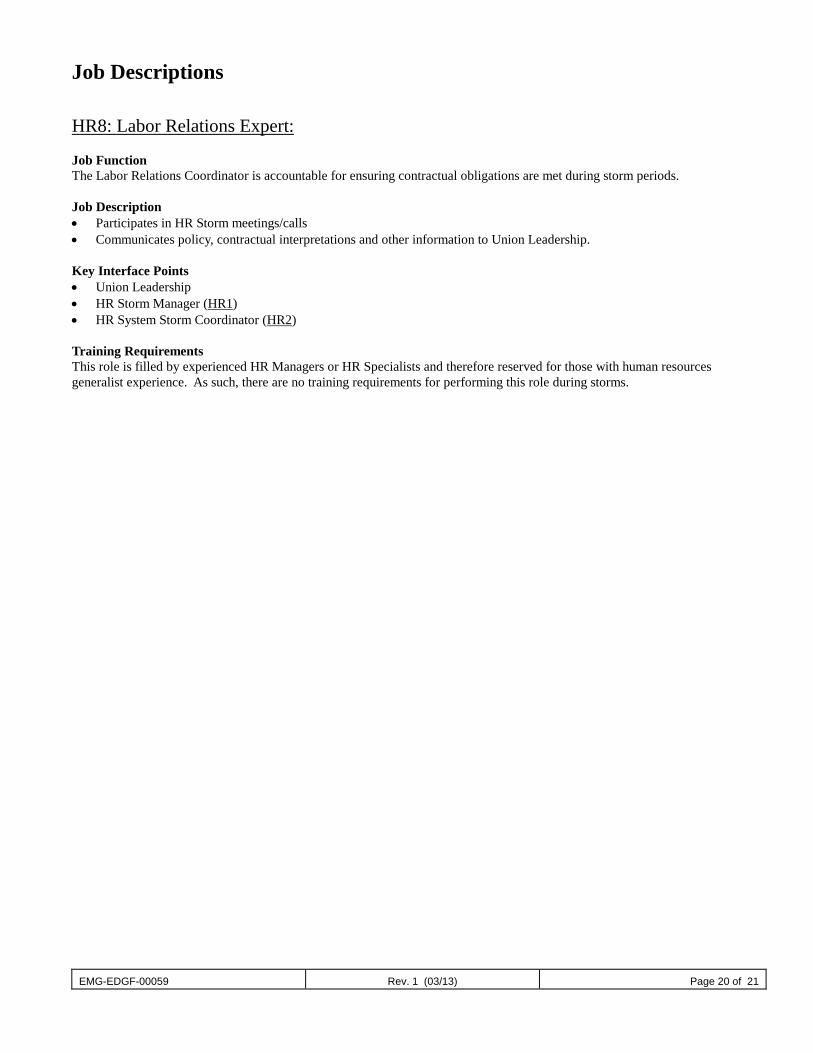
EMG-EDGF-00059 Rev. 1 (03/13) Page 20 of 21
Job Descriptions HR8: Labor Relations Expert: Job Function The Labor Relations Coordinator is accountable for ensuring contractual obligations are met during storm periods. Job Description • Participates in HR Storm meetings/calls • Communicates policy, contractual interpretations and other information to Union Leadership. Key Interface Points • Union Leadership • HR Storm Manager (HR1) • HR System Storm Coordinator (HR2) Training Requirements This role is filled by experienced HR Managers or HR Specialists and therefore reserved for those with human resources generalist experience. As such, there are no training requirements for performing this role during storms.
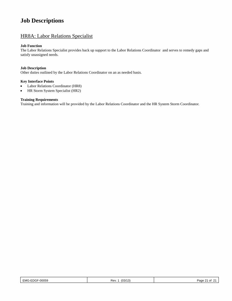
EMG-EDGF-00059 Rev. 1 (03/13) Page 21 of 21
Job Descriptions HR8A: Labor Relations Specialist Job Function The Labor Relations Specialist provides back up support to the Labor Relations Coordinator and serves to remedy gaps and satisfy unassigned needs. Job Description Other duties outlined by the Labor Relations Coordinator on an as needed basis. Key Interface Points • Labor Relations Coordinator (HR8) • HR Storm System Specialist (HR2) Training Requirements Training and information will be provided by the Labor Relations Coordinator and the HR System Storm Coordinator.
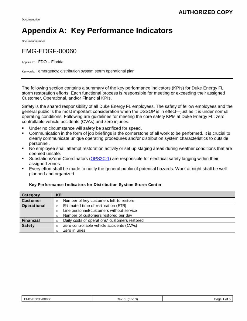
AUTHORIZED COPY
EMG-EDGF-00060 Rev. 1 (03/13) Page 1 of 5
Document title
Appendix A: Key Performance Indicators Document number
EMG-EDGF-00060 Applies to: FDO – Florida Keywords: emergency; distribution system storm operational plan The following section contains a summary of the key performance indicators (KPIs) for Duke Energy FL storm restoration efforts. Each functional process is responsible for meeting or exceeding their assigned Customer, Operational, and/or Financial KPIs.
Safety is the shared responsibility of all Duke Energy FL employees. The safety of fellow employees and the general public is the most important consideration when the DSSOP is in effect—just as it is under normal operating conditions. Following are guidelines for meeting the core safety KPIs at Duke Energy FL: zero controllable vehicle accidents (CVAs) and zero injuries. Under no circumstance will safety be sacrificed for speed. Communication in the form of job briefings is the cornerstone of all work to be performed. It is crucial to
clearly communicate unique operating procedures and/or distribution system characteristics to outside personnel.
No employee shall attempt restoration activity or set up staging areas during weather conditions that are deemed unsafe.
Substation/Zone Coordinators (OPS2C-1) are responsible for electrical safety tagging within their assigned zones.
Every effort shall be made to notify the general public of potential hazards. Work at night shall be well planned and organized.
Key Performance Indicators for Distribution System Storm Center
Category KPI Customer o Number of key customers left to restore Operational o Estimated time of restoration (ETR)
o Line personnel/customers without service o Number of customers restored per day
Financial o Daily costs of operations/ customers restored Safety o Zero controllable vehicle accidents (CVAs)
o Zero injuries
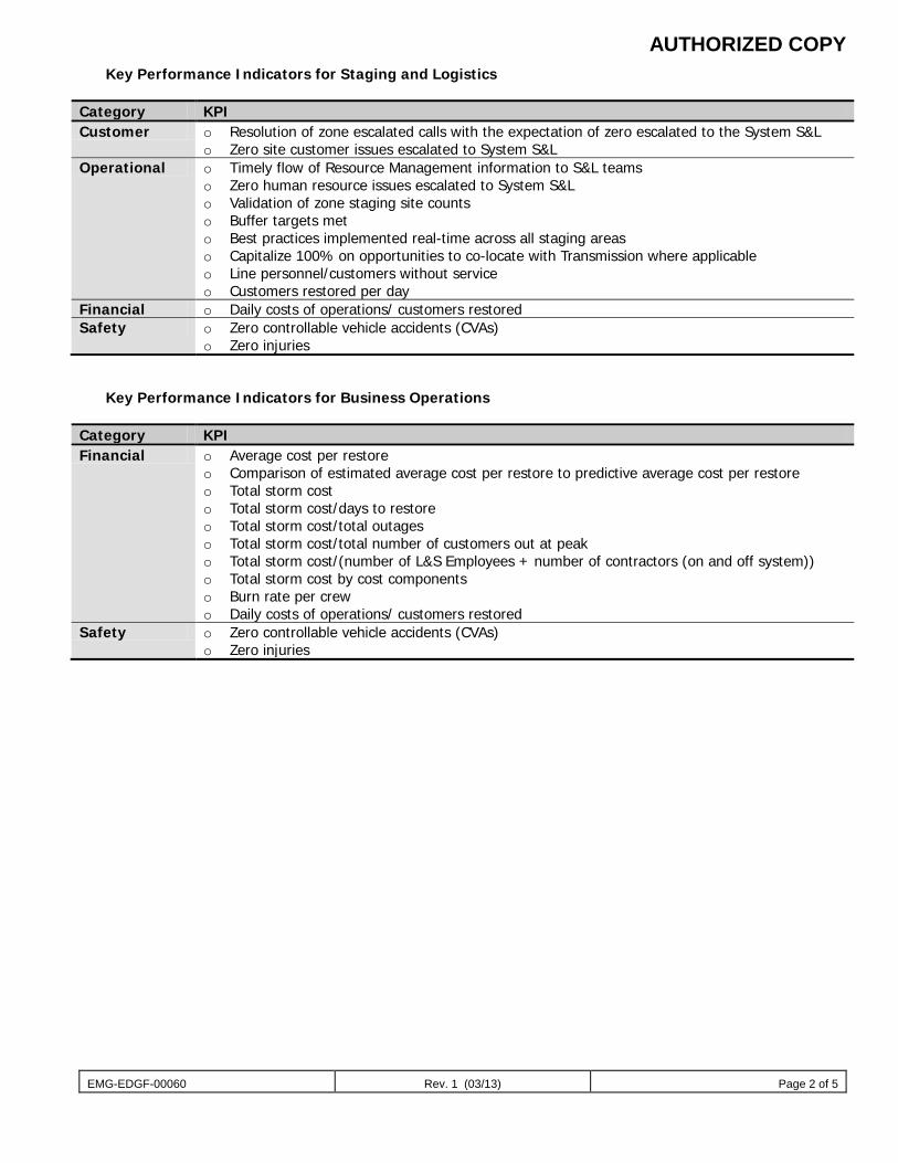
AUTHORIZED COPY
EMG-EDGF-00060 Rev. 1 (03/13) Page 2 of 5
Key Performance Indicators for Staging and Logistics
Category KPI Customer o Resolution of zone escalated calls with the expectation of zero escalated to the System S&L
o Zero site customer issues escalated to System S&L Operational o Timely flow of Resource Management information to S&L teams
o Zero human resource issues escalated to System S&L o Validation of zone staging site counts o Buffer targets met o Best practices implemented real-time across all staging areas o Capitalize 100% on opportunities to co-locate with Transmission where applicable o Line personnel/customers without service o Customers restored per day
Financial o Daily costs of operations/ customers restored Safety o Zero controllable vehicle accidents (CVAs)
o Zero injuries
Key Performance Indicators for Business Operations
Category KPI Financial o Average cost per restore
o Comparison of estimated average cost per restore to predictive average cost per restore o Total storm cost o Total storm cost/days to restore o Total storm cost/total outages o Total storm cost/total number of customers out at peak o Total storm cost/(number of L&S Employees + number of contractors (on and off system)) o Total storm cost by cost components o Burn rate per crew o Daily costs of operations/ customers restored
Safety o Zero controllable vehicle accidents (CVAs) o Zero injuries
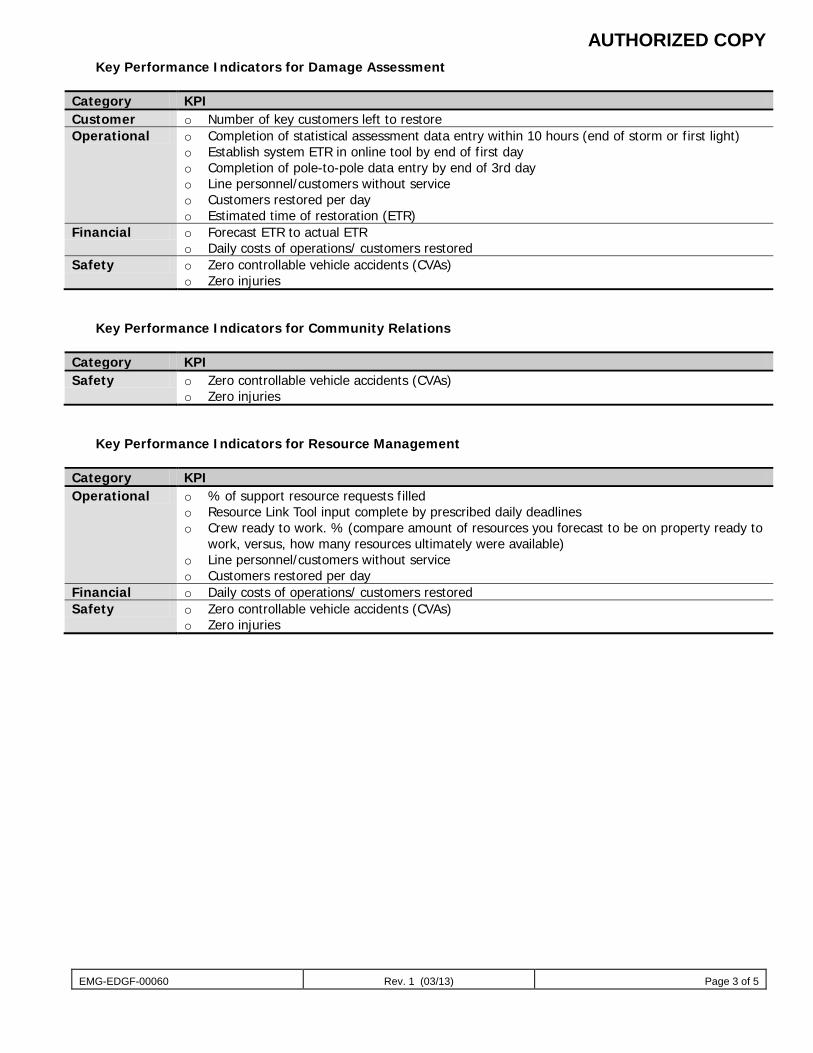
AUTHORIZED COPY
EMG-EDGF-00060 Rev. 1 (03/13) Page 3 of 5
Key Performance Indicators for Damage Assessment
Category KPI Customer o Number of key customers left to restore Operational o Completion of statistical assessment data entry within 10 hours (end of storm or first light)
o Establish system ETR in online tool by end of first day o Completion of pole-to-pole data entry by end of 3rd day o Line personnel/customers without service o Customers restored per day o Estimated time of restoration (ETR)
Financial o Forecast ETR to actual ETR o Daily costs of operations/ customers restored
Safety o Zero controllable vehicle accidents (CVAs) o Zero injuries
Key Performance Indicators for Community Relations
Category KPI Safety o Zero controllable vehicle accidents (CVAs)
o Zero injuries
Key Performance Indicators for Resource Management
Category KPI Operational o % of support resource requests filled
o Resource Link Tool input complete by prescribed daily deadlines o Crew ready to work. % (compare amount of resources you forecast to be on property ready to
work, versus, how many resources ultimately were available) o Line personnel/customers without service o Customers restored per day
Financial o Daily costs of operations/ customers restored Safety o Zero controllable vehicle accidents (CVAs)
o Zero injuries
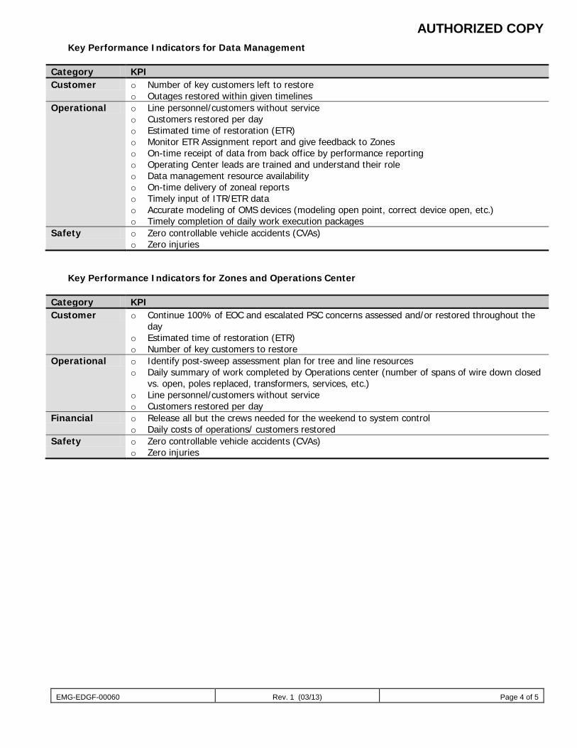
AUTHORIZED COPY
EMG-EDGF-00060 Rev. 1 (03/13) Page 4 of 5
Key Performance Indicators for Data Management
Category KPI Customer o Number of key customers left to restore
o Outages restored within given timelines Operational o Line personnel/customers without service
o Customers restored per day o Estimated time of restoration (ETR) o Monitor ETR Assignment report and give feedback to Zones o On-time receipt of data from back office by performance reporting o Operating Center leads are trained and understand their role o Data management resource availability o On-time delivery of zoneal reports o Timely input of ITR/ETR data o Accurate modeling of OMS devices (modeling open point, correct device open, etc.) o Timely completion of daily work execution packages
Safety o Zero controllable vehicle accidents (CVAs) o Zero injuries
Key Performance Indicators for Zones and Operations Center
Category KPI Customer o Continue 100% of EOC and escalated PSC concerns assessed and/or restored throughout the
day o Estimated time of restoration (ETR) o Number of key customers to restore
Operational o Identify post-sweep assessment plan for tree and line resources o Daily summary of work completed by Operations center (number of spans of wire down closed
vs. open, poles replaced, transformers, services, etc.) o Line personnel/customers without service o Customers restored per day
Financial o Release all but the crews needed for the weekend to system control o Daily costs of operations/ customers restored
Safety o Zero controllable vehicle accidents (CVAs) o Zero injuries
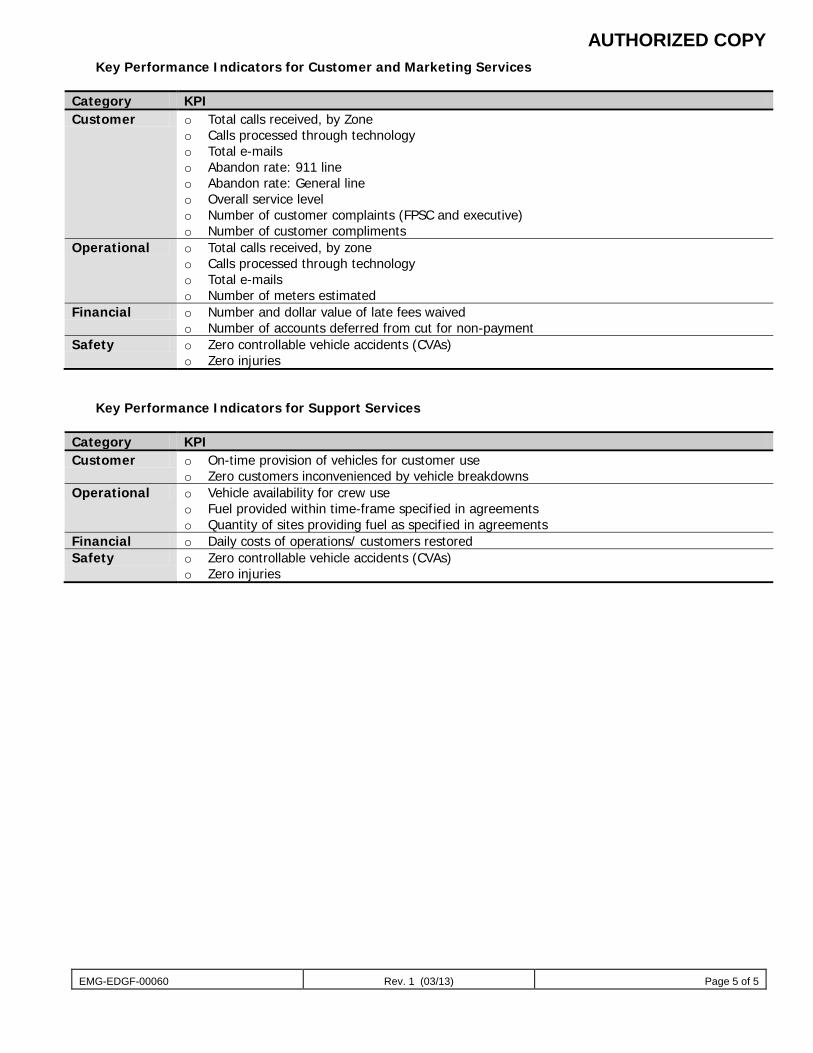
AUTHORIZED COPY
EMG-EDGF-00060 Rev. 1 (03/13) Page 5 of 5
Key Performance Indicators for Customer and Marketing Services
Category KPI Customer o Total calls received, by Zone
o Calls processed through technology o Total e-mails o Abandon rate: 911 line o Abandon rate: General line o Overall service level o Number of customer complaints (FPSC and executive) o Number of customer compliments
Operational o Total calls received, by zone o Calls processed through technology o Total e-mails o Number of meters estimated
Financial o Number and dollar value of late fees waived o Number of accounts deferred from cut for non-payment
Safety o Zero controllable vehicle accidents (CVAs) o Zero injuries
Key Performance Indicators for Support Services
Category KPI Customer o On-time provision of vehicles for customer use
o Zero customers inconvenienced by vehicle breakdowns Operational o Vehicle availability for crew use
o Fuel provided within time-frame specified in agreements o Quantity of sites providing fuel as specified in agreements
Financial o Daily costs of operations/ customers restored Safety o Zero controllable vehicle accidents (CVAs)
o Zero injuries
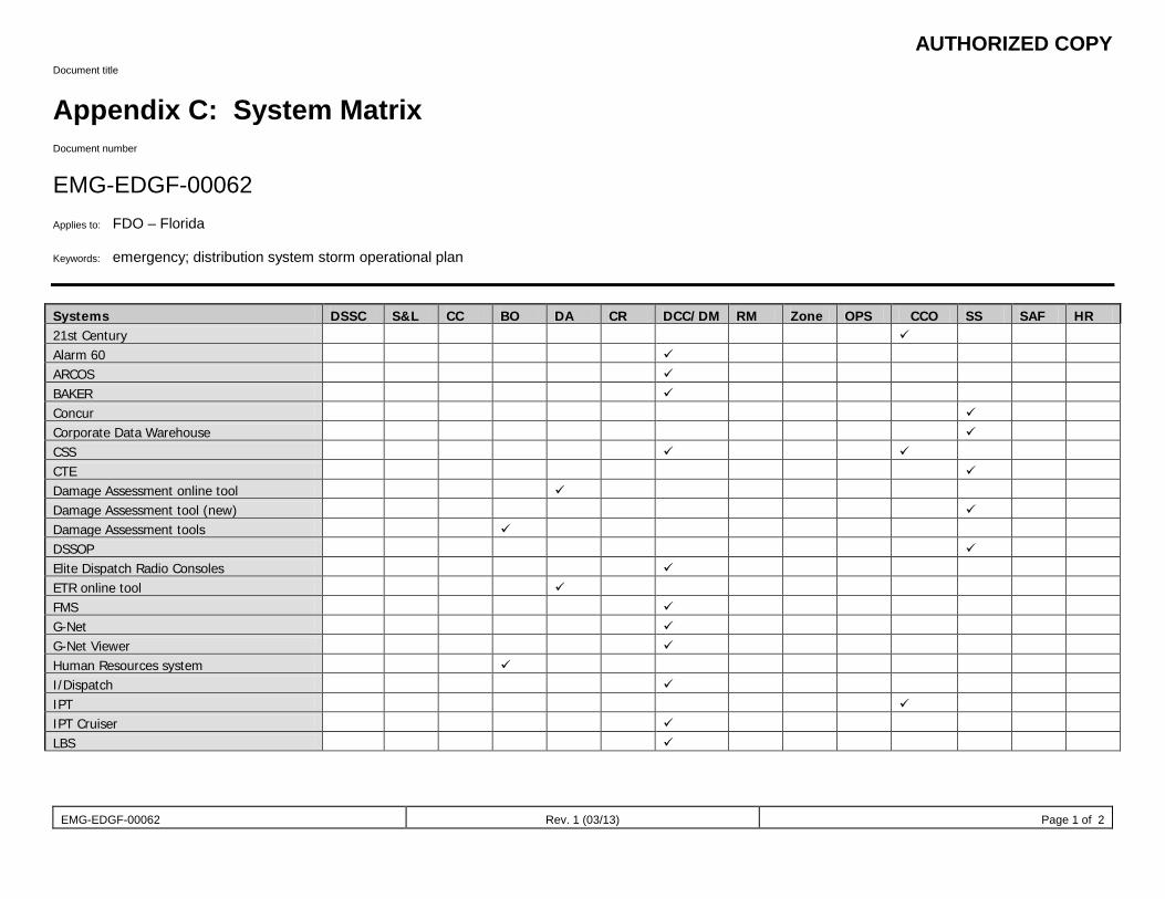
AUTHORIZED COPY
EMG-EDGF-00062 Rev. 1 (03/13) Page 1 of 2
Document title
Appendix C: System Matrix Document number
EMG-EDGF-00062 Applies to: FDO – Florida Keywords: emergency; distribution system storm operational plan Systems DSSC S&L CC BO DA CR DCC/DM RM Zone OPS CCO SS SAF HR 21st Century Alarm 60 ARCOS BAKER Concur Corporate Data Warehouse CSS CTE Damage Assessment online tool Damage Assessment tool (new) Damage Assessment tools DSSOP Elite Dispatch Radio Consoles ETR online tool FMS G-Net G-Net Viewer Human Resources system I/Dispatch IPT IPT Cruiser LBS
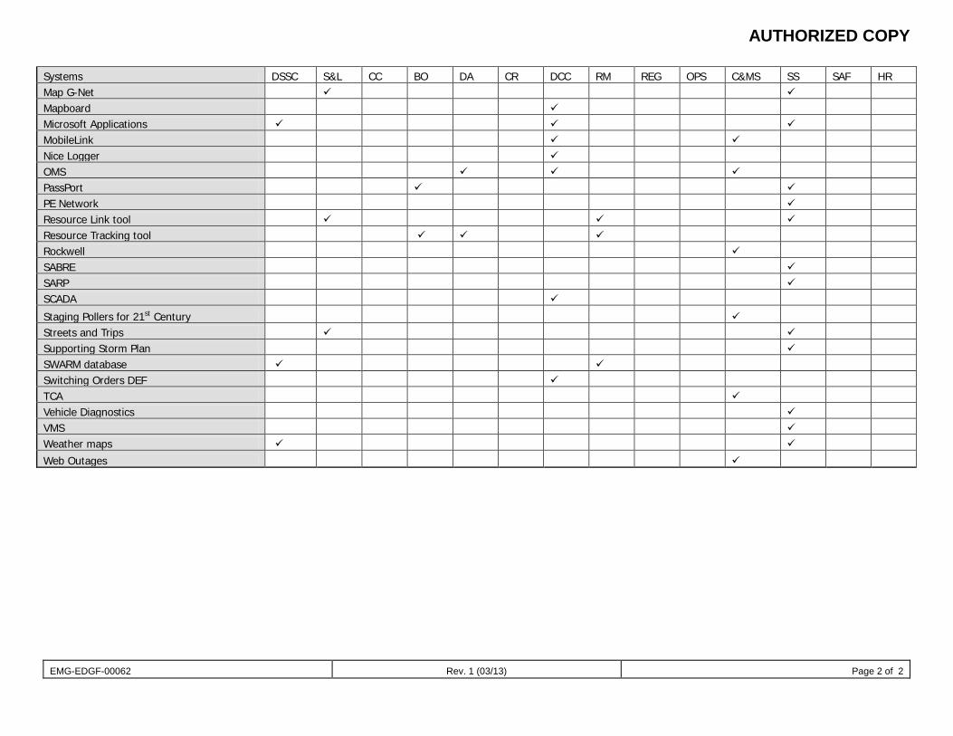
AUTHORIZED COPY
EMG-EDGF-00062 Rev. 1 (03/13) Page 2 of 2
Systems DSSC S&L CC BO DA CR DCC RM REG OPS C&MS SS SAF HR Map G-Net Mapboard Microsoft Applications MobileLink Nice Logger OMS PassPort PE Network Resource Link tool Resource Tracking tool Rockwell SABRE SARP SCADA
Staging Pollers for 21st Century Streets and Trips Supporting Storm Plan SWARM database Switching Orders DEF TCA Vehicle Diagnostics VMS Weather maps
Web Outages
AUTHORIZED COPY
EMG-EDGF-00063 Rev. 2 (11/13) Page 1 of 2
Document title
Appendix D: Abbreviations Document number
EMG-EDGF-00063 Applies to: Florida Delivery Operations Keywords: emergency; distribution system storm operational plan ACD: Automated Call Distribution
AIR: Assess, Isolate, and Restore
AIRD: Assess, Isolate, Restore, and Document
ARCOS: Automated Roster Callout System
CCD: Corporate Communications Department
CCO: Customer Contact Operations
CRI: Convergent Resources, Inc.
CSC: Customer Service Center
CSS: Customer Service System
CTE: Corporate Time Entry
CVA: Controllable vehicle accident
DE: Duke Energy
DA: Damage Assessment
DM: Data Management
DCC: Distribution Contact Center
DIS: Distribution Information System
DSSC: Distribution System Storm Center
DSSOP: Distribution System Storm Operational Plan
EOC: Emergency Operations Center
ETR: Estimated time of restoration
F/S: Final Sweep
GAAP: Generally Accepted Accounting Principles
GIS: Geographic Information System
GPS: Global Positioning System
AUTHORIZED COPY
EMG-EDGF-00063 Rev. 2 (11/13) Page 2 of 2
IPT: Immediate Problem Ticket
IVR: Interactive Voice Response
IT&T: Information Technology and Telecommunications
JE: journal entry
KPI: Key performance indicator
LAM: Large Account Management
L&S: Line and Service Department (PEC only)
LSC: Local Storm Center (PEC only)
MOMS: Mobile Outage Management System
OMS: Outage Management System
OPOC: Operations Point of Contact (Operations Center Coordinator (OPS1)
POC: Point of contact
POD: Point of delivery
POG: Power Operations Group/Generation
PPE: Personal protective equipment
PSC: Public Service Commission
RSVP: Resource Storm Volunteer Program
S&L: Staging and Logistics
SCADA: Supervisory Control and Data Acquisition
SEE: Southeastern Electric Exchange
SSOL: Staging Site Operational Leader
TCA: Trouble Call Analysis
TOC: Technology Operations Center
VMS Vehicle Management System
WBS: Work breakdown structure
ZRM: Zone Resource Manager
ZSM: Zone Storm Manager

ATTACHMENT Z
AUTHORIZED COPY
Transmission Florida Storm Plan REV May 1, 2013 Page 1 of 43
Transmission Florida Storm Plan
AUTHORIZED COPY
Transmission Florida Storm Plan Revised May 1, 2013
Page 2 of 43
Transmission Storm Plan Florida Document number TRM-STRM-2013
Table of Contents 1.0 PURPOSE ...................................................................................................................................... 4
2.0 Storm/Emergency Classification ................................................................................................. 4
2.1 Level I ............................................................................................................................................ 4
2.2 Level I Examples ........................................................................................................................... 4
2.3 Level II ........................................................................................................................................... 5
2.4 Level II Examples .......................................................................................................................... 5
2.5 Level III .......................................................................................................................................... 5
2.6 Level III Examples ......................................................................................................................... 6
2.6 Level IV .......................................................................................................................................... 6
2.6 Level IV Examples ........................................................................................................................ 6
3.0 Storm Activation and Communication ........................................................................................ 6
4.0 Transmission Florida Storm Center ............................................................................................ 7
4.2 Restoration Priority ...................................................................................................................... 7
4.3 Transmission Storm Center Setup .............................................................................................. 8
5.0 Conference Call Agenda/Checklist .............................................................................................. 9
6.0 Transmission Logistics Center ...................................................................................................11
6.1 Logistics Center Duties and Responsibilities ...........................................................................11
6.2 Logistics Support Coordinator .................................................................................................. 12
6.3 Contracts Support Team ............................................................................................................ 14
6.4 Materials Team ............................................................................................................................ 16
6.5 Administrative Team ................................................................................................................... 17
6.6 Heavy Hauling Team ................................................................................................................... 17
7.0 Wholesale Customer .................................................................................................................. 19
7.1 Wholesale Customers Duties and Responsibilities ................................................................. 19
8.0 Maintenance Areas Preface ....................................................................................................... 19
9.0 Pre-Storm Preparation Timelines .............................................................................................. 22
9.1 Area Transmission Coordinator Pre-Storm Checklist .............................................................. 22
9.2 Staff Engineer Pre-Storm Checklist ........................................................................................... 24
9.3 Maintenance Supervisor Pre-Storm Checklist .......................................................................... 26
9.4 Forester Pre-Storm Checklist .................................................................................................... 28
AUTHORIZED COPY
Transmission Florida Storm Plan Revised May 1, 2013
Page 3 of 43
9.5 Administrative Assistant Pre-Storm Checklist ......................................................................... 30
10.0 Links to Local Area Contacts ..................................................................................................... 31
10.1 Florida NTA ................................................................................................................................. 31
10.2 Florida STA .................................................................................................................................. 31
11.0 Transmission Maintenance Area Storm Plan Accounting Procedures ................................... 31
12.0 Nuclear Plant Siren Restoration Plan ........................................................................................ 31
13.0 Environmental Contacts ............................................................................................................. 32
14.0 Health and Safety Services System Storm Plan Instructions .................................................. 32
14.1 Health and Safety Services Transmission Support .................................................................. 32
15.0 Pre-Event Briefing ...................................................................................................................... 32
15.1 Working in Windy Conditions .................................................................................................... 32
15.2 Use of Transmission Class Bucket Trucks in Windy Conditions ............................................ 33
15.3 Work Coordination ..................................................................................................................... 33
16.0 Health and Safety Services Regional Storm Plan Instructions ............................................... 34
16.1 Instructions for use of safety information ................................................................................ 34
16.2 Designated Safety Representatives Regional Storm Plan ....................................................... 34
16.3 Storm Safety Message Link ....................................................................................................... 34
17.0 Contract and Accounting Procedures ....................................................................................... 34
17.1 Contract Provisions for Storm Work ......................................................................................... 34
17.2 Construction and Clearing Contractors .................................................................................... 35
17.3 Construction and Clearing Contractors Instructions ............................................................... 35
18.0 Transmission Storm Credit Card Procedures ........................................................................... 36
18.1 Transmission Accounting Task Numbers - FL .......................................................................... 37
19.0 Telecom and External Contacts ................................................................................................. 37
20.0 Florida Emergency Operations Center ...................................................................................... 38
20.1 State Emergency Personnel ....................................................................................................... 38
21.0 Mutual Assistance Rosters ........................................................................................................ 39
22.0 Neighboring Utility Contacts ...................................................................................................... 39
23.0 Current Road Conditions ........................................................................................................... 39
24.0 Current Road Conditions ........................................................................................................... 39
25.0 Post Storm Analysis Florida ...................................................................................................... 39
26.0 Transmission FL Typical Storm Communications Diagram (ATTACHMENT 1) ...................... 40
27.0 Transmission FL Coordinator Organization Chart (ATTACHMENT 2) ..................................... 41
28.0 Transmission FL System Contacts ............................................................................................ 42
AUTHORIZED COPY
Transmission Florida Storm Plan Revised May 1, 2013
Page 4 of 43
1.0 Purpose
The Transmission Storm Plan, in keeping with the corporate guideline, has been developed for use when either catastrophic damage to transmission facilities has occurred and the repair is beyond the capability of the local Transmission Maintenance Area personnel, or the National Weather Service issues a wide area severe weather warning (e.g., hurricane or ice storm expected to hit the Duke Energy service area).
2.0 Storm/Emergency Classification
The Transmission Storm response is controlled and managed by multiple Storm Centers. The Storm Centers and their associated roles and responsibilities are listed below. The storm/emergency classifications are also listed below. 2.1 Level I - Command and Control.
Storms or events that affect or could affect only one Transmission Maintenance Area with low to moderate damage. Restoration is normally accomplished by the affected area's resources without outside assistance.
• Transmission Maintenance Area Storm Center is functioning (responsible for assessing needs, coordinating all assigned resources and restoration efforts within their respective areas).
• Transmission Maintenance Area is responsible for obtaining materials, major equipment, engineering support, general office support, fault locations and additional crews through normal methods (note: Transmission Maintenance Area may contact Logistics Center lead and request assistance).
• Transmission Storm Center is not manned, but Transmission Maintenance Area Coordinator and Transmission Storm Coordinator need to determine if updates on conference calls are needed to assist and facilitate mobilization decisions and resource needs.
2.2 Level I Examples - • Anticipated large number of distribution breaker operations. • Loss of offsite power at Nuclear Plant (see note 1). • Event of High Interest to Public or Media (see note 1). • Single Transmission Line Locked out. • Single Transformer Failure that the Transmission Maintenance Area can
handle with own resources. • Single Regulator Failure that Transmission Maintenance Area can handle
with own resources. Note 1: May be elevated to Level II, depending on need as determined by affected Transmission Maintenance Area and Transmission Storm Center.
TRANSMISSION - FLORIDA
STORM PLAN
AUTHORIZED COPY
Transmission Florida Storm Plan Revised May 1, 2013
Page 5 of 43
2.3 Level II- Command and Control.
Storms or events with moderate damage affecting one or more Transmission Maintenance Area. Damage in the maintenance area may require the use of crews from other Transmission Maintenance Areas or Transmission Construction in order to be repaired in a timely manner.
• Transmission Maintenance Area Storm Centers are open (responsible for assessing needs, coordinating all assigned resources and restoration efforts within their respective areas).
• Logistics Center is open for engineering, materials, contracting, accounting, fault locations, General Office and scheduling support.
• Transmission Storm Center is not manned, but holds updates on conference calls to assist with restoration efforts and facilitate mobilization decisions. The Transmission Storm Center will also resolve conflicts for competing resources, materials and contractors.
• Transmission Storm Center will represent Transmission on Distribution System Storm Conference Calls.
2.4 Level II Examples -
• Events that affect critical customers with sustained outage or that Transmission Maintenance Area cannot handle.
• Anticipated ice accumulation level of 3/8” to ½”. • Lockout of two transmission lines in the same area at the same time, which
Transmission Maintenance Area cannot handle with regularly available resources.
• Lockout of two Subs at the same time in one Transmission Maintenance Area, which cannot be handled with regularly available resources.
• Event threatening Major Generation Availability. • Loss of offsite power at Nuclear Plant (see note 1) • Event of High Interest to Public or Media (see note 1). • Event where out-of-Area (on-system) crews/resources are needed
Note 1: When elevated from Level I by affected Transmission Maintenance Area Manager and Transmission Storm Center.
2.5 Level III - Command and Control Storms or events causing damage to one or more Transmission Maintenance Area requiring the assistance of the Transmission Storm Center, Logistics Center, and Wholesale Customer Storm Center. Restoration efforts require the use of on-system contractors, possible off-system contractors, other utilities and personnel from other Transmission Maintenance Areas.
• Transmission Storm Center is open (responsible for coordinating inter-maintenance area efforts and serving as a liaison to Senior Management and Corporate Communications/media).
• Transmission Maintenance Area Storm Centers are open (responsible for assessing needs, coordinating all assigned resources and restoration efforts within their respective areas).
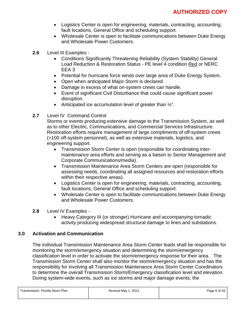
AUTHORIZED COPY
Transmission Florida Storm Plan Revised May 1, 2013
Page 6 of 43
• Logistics Center is open for engineering, materials, contracting, accounting, fault locations, General Office and scheduling support.
• Wholesale Center is open to facilitate communications between Duke Energy and Wholesale Power Customers.
2.6 Level III Examples - • Conditions Significantly Threatening Reliability (System Stability) General
Load Reduction & Restoration Status - PE level 4 condition Red or NERC EEA 3
• Potential for hurricane force winds over large area of Duke Energy System. • Open when anticipated Major Storm is declared. • Damage in excess of what on-system crews can handle. • Event of significant Civil Disturbance that could cause significant power
disruption. • Anticipated ice accumulation level of greater than ½”.
2.7 Level IV Command Control Storms or events producing extensive damage to the Transmission System, as well as to other Electric, Communications, and Commercial Services Infrastructure. Restoration efforts require management of large compliments of off-system crews (>100 off-system personnel), as well as extensive materials, logistics, and engineering support.
• Transmission Storm Center is open (responsible for coordinating inter-maintenance area efforts and serving as a liaison to Senior Management and Corporate Communications/media).
• Transmission Maintenance Area Storm Centers are open (responsible for assessing needs, coordinating all assigned resources and restoration efforts within their respective areas).
• Logistics Center is open for engineering, materials, contracting, accounting, fault locations, General Office and scheduling support.
• Wholesale Center is open to facilitate communications between Duke Energy and Wholesale Power Customers.
2.8 Level IV Examples - • Heavy Category III (or stronger) Hurricane and accompanying tornadic
activity producing widespread structural damage to lines and substations. 3.0 Activation and Communication
The individual Transmission Maintenance Area Storm Center leads shall be responsible for monitoring the storm/emergency situation and determining the storm/emergency classification level in order to activate the storm/emergency response for their area. The Transmission Storm Center shall also monitor the storm/emergency situation and has the responsibility for involving all Transmission Maintenance Area Storm Center Coordinators to determine the overall Transmission Storm/Emergency classification level and elevation. During system-wide events, such as ice storms and major damage events, the
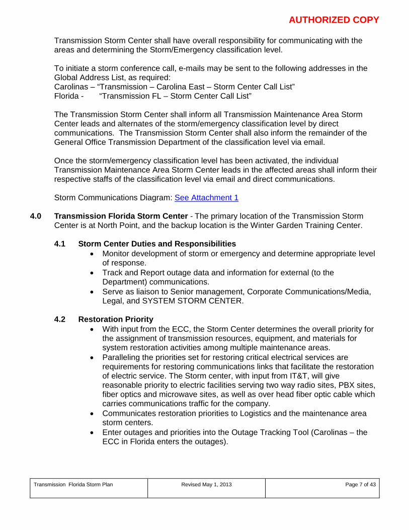
AUTHORIZED COPY
Transmission Florida Storm Plan Revised May 1, 2013
Page 7 of 43
Transmission Storm Center shall have overall responsibility for communicating with the areas and determining the Storm/Emergency classification level.
To initiate a storm conference call, e-mails may be sent to the following addresses in the Global Address List, as required:
Carolinas – “Transmission – Carolina East – Storm Center Call List” Florida - “Transmission FL – Storm Center Call List”
The Transmission Storm Center shall inform all Transmission Maintenance Area Storm Center leads and alternates of the storm/emergency classification level by direct communications. The Transmission Storm Center shall also inform the remainder of the General Office Transmission Department of the classification level via email.
Once the storm/emergency classification level has been activated, the individual Transmission Maintenance Area Storm Center leads in the affected areas shall inform their respective staffs of the classification level via email and direct communications. Storm Communications Diagram: See Attachment 1
4.0 Transmission Florida Storm Center - The primary location of the Transmission Storm Center is at North Point, and the backup location is the Winter Garden Training Center.
4.1 Storm Center Duties and Responsibilities
• Monitor development of storm or emergency and determine appropriate level of response.
• Track and Report outage data and information for external (to the Department) communications.
• Serve as liaison to Senior management, Corporate Communications/Media, Legal, and SYSTEM STORM CENTER.
4.2 Restoration Priority
• With input from the ECC, the Storm Center determines the overall priority for the assignment of transmission resources, equipment, and materials for system restoration activities among multiple maintenance areas.
• Paralleling the priorities set for restoring critical electrical services are requirements for restoring communications links that facilitate the restoration of electric service. The Storm center, with input from IT&T, will give reasonable priority to electric facilities serving two way radio sites, PBX sites, fiber optics and microwave sites, as well as over head fiber optic cable which carries communications traffic for the company.
• Communicates restoration priorities to Logistics and the maintenance area storm centers.
• Enter outages and priorities into the Outage Tracking Tool (Carolinas – the ECC in Florida enters the outages).
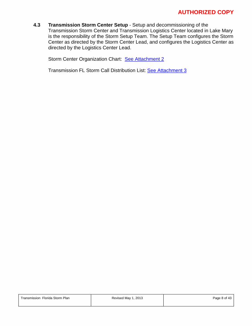
AUTHORIZED COPY
Transmission Florida Storm Plan Revised May 1, 2013
Page 8 of 43
4.3 Transmission Storm Center Setup - Setup and decommissioning of the Transmission Storm Center and Transmission Logistics Center located in Lake Mary is the responsibility of the Storm Setup Team. The Setup Team configures the Storm Center as directed by the Storm Center Lead, and configures the Logistics Center as directed by the Logistics Center Lead.
Storm Center Organization Chart: See Attachment 2
Transmission FL Storm Call Distribution List: See Attachment 3
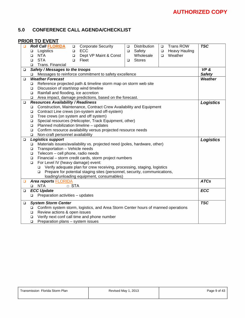
AUTHORIZED COPY
Transmission Florida Storm Plan Revised May 1, 2013
Page 9 of 43
5.0 CONFERENCE CALL AGENDA/CHECKLIST PRIOR TO EVENT Roll Call FLORIDA
Logistics NTA STA Trans. Financial
Corporate Security ECC Dept VP Maint & Const Fleet
Distribution Safety
Wholesale Stores
Trans ROW Heavy Hauling Weather
TSC
Safety / Messages to the troops Messages to reinforce commitment to safety excellence
VP & Safety
Weather Forecast Reference projected path & timeline storm map on storm web site Discussion of start/stop wind timeline Rainfall and flooding, ice accretion Area impact, damage predictions, based on the forecast.
Weather
Resources Availability / Readiness Construction, Maintenance, Contract Crew Availability and Equipment Contract Line crews (on-system and off-system) Tree crews (on system and off system) Special resources (Helicopter, Track Equipment, other) Planned mobilization timeline – updates Confirm resource availability versus projected resource needs Non-craft personnel availability
Logistics
Logistics support Materials issues/availability vs. projected need (poles, hardware, other) Transportation – Vehicle needs Telecom – cell phone, radio needs Financial – storm credit cards, storm project numbers For Level IV (heavy damage) event:
Verify adequate plan for crew receiving, processing, staging, logistics Prepare for potential staging sites (personnel, security, communications,
loading/unloading equipment, consumables)
Logistics
Area reports FLORIDA NTA □ STA
ATCs
ECC Update Preparation activities – updates
ECC
System Storm Center Confirm system storm, logistics, and Area Storm Center hours of manned operations Review actions & open issues Verify next conf call time and phone number Preparation plans – system issues
TSC
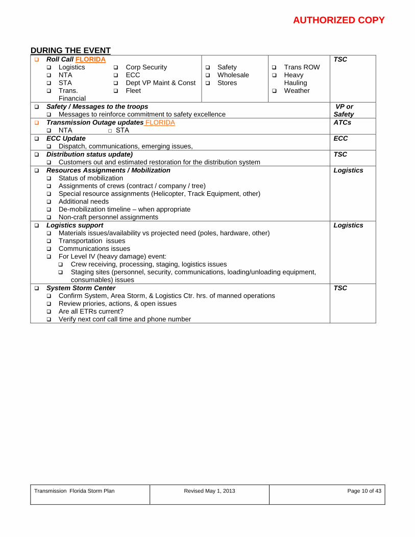
AUTHORIZED COPY
Transmission Florida Storm Plan Revised May 1, 2013
Page 10 of 43
DURING THE EVENT Roll Call FLORIDA
Logistics NTA STA Trans.
Financial
Corp Security ECC Dept VP Maint & Const Fleet
Safety Wholesale Stores
Trans ROW Heavy
Hauling Weather
TSC
Safety / Messages to the troops Messages to reinforce commitment to safety excellence
VP or Safety
Transmission Outage updates FLORIDA NTA □ STA
ATCs
ECC Update Dispatch, communications, emerging issues,
ECC
Distribution status update) Customers out and estimated restoration for the distribution system
TSC
Resources Assignments / Mobilization Status of mobilization Assignments of crews (contract / company / tree) Special resource assignments (Helicopter, Track Equipment, other) Additional needs De-mobilization timeline – when appropriate Non-craft personnel assignments
Logistics
Logistics support Materials issues/availability vs projected need (poles, hardware, other) Transportation issues Communications issues For Level IV (heavy damage) event:
Crew receiving, processing, staging, logistics issues Staging sites (personnel, security, communications, loading/unloading equipment,
consumables) issues
Logistics
System Storm Center Confirm System, Area Storm, & Logistics Ctr. hrs. of manned operations Review priories, actions, & open issues Are all ETRs current? Verify next conf call time and phone number
TSC
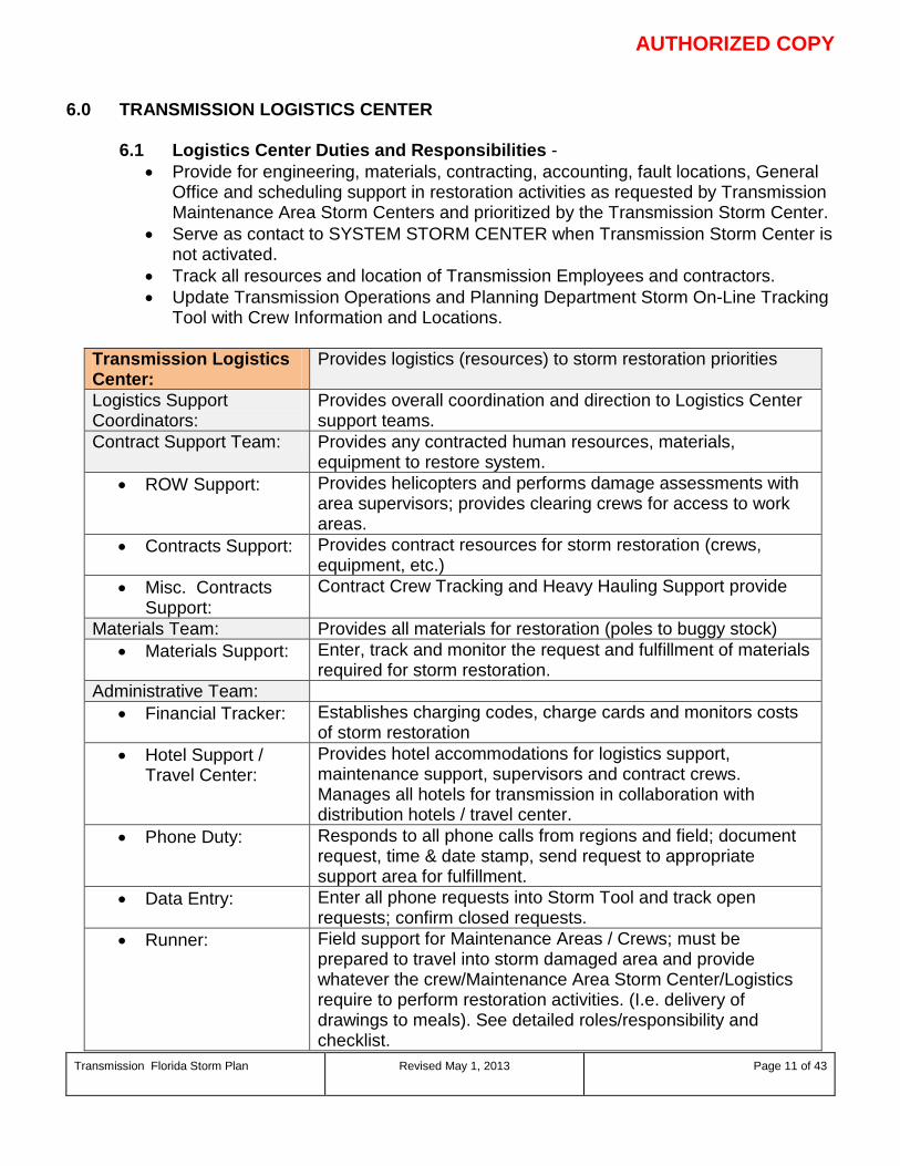
AUTHORIZED COPY
Transmission Florida Storm Plan Revised May 1, 2013
Page 11 of 43
6.0 TRANSMISSION LOGISTICS CENTER
6.1 Logistics Center Duties and Responsibilities - • Provide for engineering, materials, contracting, accounting, fault locations, General
Office and scheduling support in restoration activities as requested by Transmission Maintenance Area Storm Centers and prioritized by the Transmission Storm Center.
• Serve as contact to SYSTEM STORM CENTER when Transmission Storm Center is not activated.
• Track all resources and location of Transmission Employees and contractors. • Update Transmission Operations and Planning Department Storm On-Line Tracking
Tool with Crew Information and Locations.
Transmission Logistics Center:
Provides logistics (resources) to storm restoration priorities
Logistics Support Coordinators:
Provides overall coordination and direction to Logistics Center support teams.
Contract Support Team: Provides any contracted human resources, materials, equipment to restore system.
• ROW Support: Provides helicopters and performs damage assessments with area supervisors; provides clearing crews for access to work areas.
• Contracts Support: Provides contract resources for storm restoration (crews, equipment, etc.)
• Misc. Contracts Support:
Contract Crew Tracking and Heavy Hauling Support provide
Materials Team: Provides all materials for restoration (poles to buggy stock) • Materials Support: Enter, track and monitor the request and fulfillment of materials
required for storm restoration. Administrative Team:
• Financial Tracker: Establishes charging codes, charge cards and monitors costs of storm restoration
• Hotel Support / Travel Center:
Provides hotel accommodations for logistics support, maintenance support, supervisors and contract crews. Manages all hotels for transmission in collaboration with distribution hotels / travel center.
• Phone Duty: Responds to all phone calls from regions and field; document request, time & date stamp, send request to appropriate support area for fulfillment.
• Data Entry: Enter all phone requests into Storm Tool and track open requests; confirm closed requests.
• Runner: Field support for Maintenance Areas / Crews; must be prepared to travel into storm damaged area and provide whatever the crew/Maintenance Area Storm Center/Logistics require to perform restoration activities. (I.e. delivery of drawings to meals). See detailed roles/responsibility and checklist.
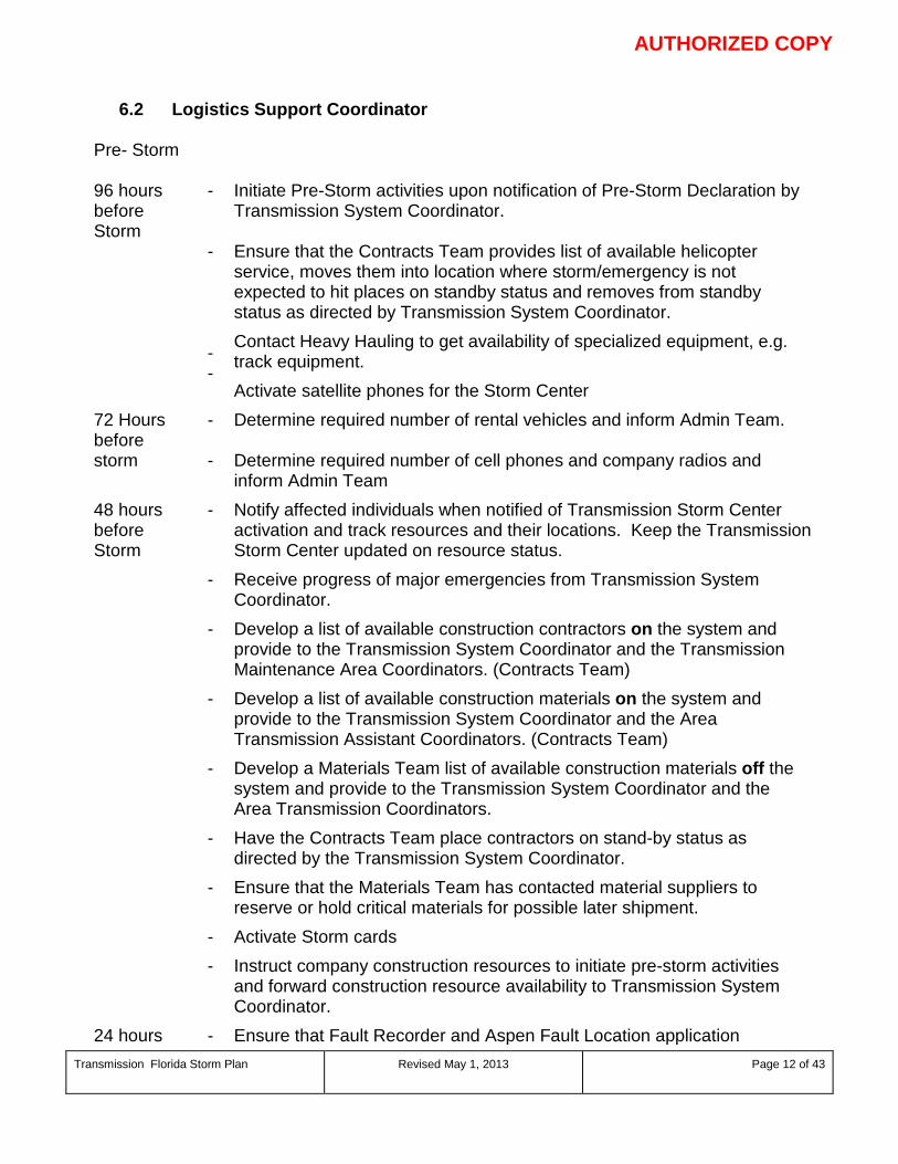
AUTHORIZED COPY
Transmission Florida Storm Plan Revised May 1, 2013
Page 12 of 43
6.2 Logistics Support Coordinator
Pre- Storm
96 hours before Storm
- Initiate Pre-Storm activities upon notification of Pre-Storm Declaration by Transmission System Coordinator.
- - -
Ensure that the Contracts Team provides list of available helicopter service, moves them into location where storm/emergency is not expected to hit places on standby status and removes from standby status as directed by Transmission System Coordinator. Contact Heavy Hauling to get availability of specialized equipment, e.g. track equipment. Activate satellite phones for the Storm Center
72 Hours before
- Determine required number of rental vehicles and inform Admin Team.
storm - Determine required number of cell phones and company radios and inform Admin Team
48 hours before Storm
- Notify affected individuals when notified of Transmission Storm Center activation and track resources and their locations. Keep the Transmission Storm Center updated on resource status.
- Receive progress of major emergencies from Transmission System Coordinator.
- Develop a list of available construction contractors on the system and provide to the Transmission System Coordinator and the Transmission Maintenance Area Coordinators. (Contracts Team)
- Develop a list of available construction materials on the system and provide to the Transmission System Coordinator and the Area Transmission Assistant Coordinators. (Contracts Team)
- Develop a Materials Team list of available construction materials off the system and provide to the Transmission System Coordinator and the Area Transmission Coordinators.
- Have the Contracts Team place contractors on stand-by status as directed by the Transmission System Coordinator.
- Ensure that the Materials Team has contacted material suppliers to reserve or hold critical materials for possible later shipment.
- Activate Storm cards - Instruct company construction resources to initiate pre-storm activities
and forward construction resource availability to Transmission System Coordinator.
24 hours - Ensure that Fault Recorder and Aspen Fault Location application
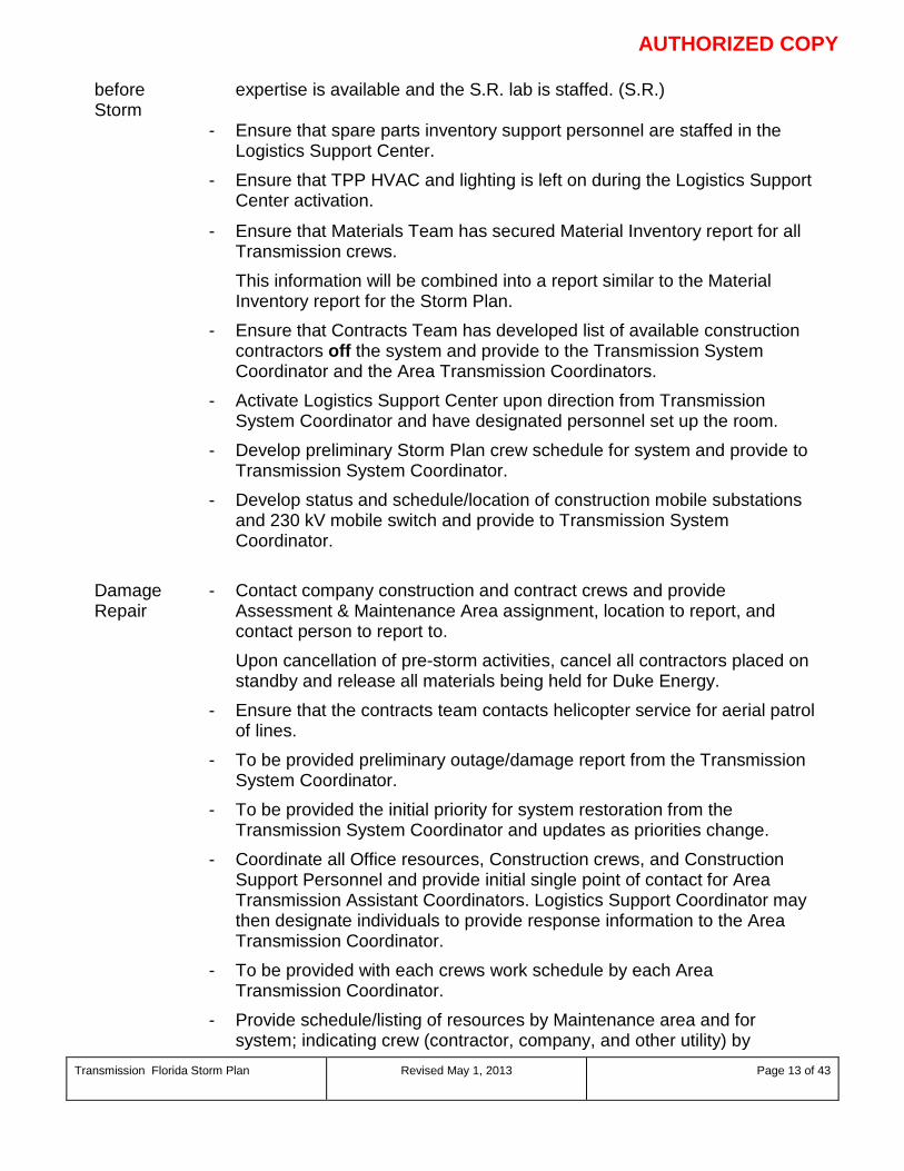
AUTHORIZED COPY
Transmission Florida Storm Plan Revised May 1, 2013
Page 13 of 43
before Storm
expertise is available and the S.R. lab is staffed. (S.R.)
- Ensure that spare parts inventory support personnel are staffed in the Logistics Support Center.
- Ensure that TPP HVAC and lighting is left on during the Logistics Support Center activation.
- Ensure that Materials Team has secured Material Inventory report for all Transmission crews.
This information will be combined into a report similar to the Material Inventory report for the Storm Plan.
- Ensure that Contracts Team has developed list of available construction contractors off the system and provide to the Transmission System Coordinator and the Area Transmission Coordinators.
- Activate Logistics Support Center upon direction from Transmission System Coordinator and have designated personnel set up the room.
- Develop preliminary Storm Plan crew schedule for system and provide to Transmission System Coordinator.
- Develop status and schedule/location of construction mobile substations and 230 kV mobile switch and provide to Transmission System Coordinator.
Damage Repair
- Contact company construction and contract crews and provide Assessment & Maintenance Area assignment, location to report, and contact person to report to.
Upon cancellation of pre-storm activities, cancel all contractors placed on standby and release all materials being held for Duke Energy.
- Ensure that the contracts team contacts helicopter service for aerial patrol of lines.
- To be provided preliminary outage/damage report from the Transmission System Coordinator.
- To be provided the initial priority for system restoration from the Transmission System Coordinator and updates as priorities change.
- Coordinate all Office resources, Construction crews, and Construction Support Personnel and provide initial single point of contact for Area Transmission Assistant Coordinators. Logistics Support Coordinator may then designate individuals to provide response information to the Area Transmission Coordinator.
- To be provided with each crews work schedule by each Area Transmission Coordinator.
- Provide schedule/listing of resources by Maintenance area and for system; indicating crew (contractor, company, and other utility) by
AUTHORIZED COPY
Transmission Florida Storm Plan Revised May 1, 2013
Page 14 of 43
functional area with supervisor’s name. This information should be provided and updated daily to the affected Area Transmission Coordinators and the Transmission System Coordinator.
- Coordinate materials and resources to the prioritized work location, as directed by the Transmission System Coordinator.
- Provide Transmission System Coordinator and all Area Transmission Coordinators with appropriate project number.
- To be provided progress of repairs on a daily basis by the Area Transmission Coordinator.
- To be provided travel conditions in each maintenance area from the Area Transmission Coordinator.
- Ensure that the materials team provides material requisition and delivery information to the Area Transmission Coordinator.
- Provide volunteers to man Family Information Center.
6.3 Contract Support Team - Timeline Storm Preparedness
Pre-Storm
96 hours before Storm
-
Initiate Pre-Storm activities upon notification of Pre-Storm Declaration by Transmission System Coordinator.
- Coordinate obtaining the number of Helicopters required by the Transmission System Coordinator and Energy Delivery, when requested by SYSTEM STORM CENTER, and place Helicopters on “Standby” as directed Carolinas – ROW Management Manager Florida - ROW Management Manager
- Place Transmission Contractors on “Standby” status as directed by the Transmission System Coordinator
72 hours before Storm
- Verify the number of Helicopters required by the Transmission System Coordinator and Energy Delivery, and place Helicopters on “Standby” as directed. Carolinas – ROW Management Manager Florida - ROW Management Manager
- Place Transmission Contractors on “Standby” status as directed by the Transmission System Coordinator
48 hours before Storm
-
Verify the number of Helicopters required by the Transmission System Coordinator, and Energy Delivery, and place Helicopters on “Standby” as directed. Carolinas – ROW Management Manager
AUTHORIZED COPY
Transmission Florida Storm Plan Revised May 1, 2013
Page 15 of 43
Florida - ROW Management Manager - Coordinate Helicopter Staging Areas, if practical and possible, and
preliminary Helicopter and Duke Energy Contact information when provided by SYSTEM STORM CENTER and Transmission System Coordinator. Note: Helicopters must be stored in hangers during storm and windy conditions for protection.
- Place Transmission Contractors on “Standby” status as directed by the Transmission System Coordinator
- Receive progress of major emergencies from Transmission System Coordinator.
- Make list of available construction contractors on the system and provide to the Transmission System Coordinator and the Area Transmission Coordinators.
24 hours before Storm
- Finalize and Coordinate Helicopter Reporting locations Contact information, when provided by SYSTEM STORM CENTER and Transmission System Coordinator.
- Provide list of available helicopter service, reporting locations, and estimated Time of Arrival.
- Make list of available construction contractors off the system and provide to the Transmission System Coordinator and the Area Transmission Coordinators.
- Place contractors on stand-by status as directed by the Transmission System Coordinator. (Contractor should be placed on “Standby” a minimum of 24 hours prior to Storm making land fall)
- Provide list of available helicopter service, move them into location where emergency is not expected to hit place on standby status and remove from standby status as directed by Transmission System Coordinator. Note: Helicopters must be stored in hangers during Storm and wind conditions for protection
- Instruct company construction resources to initiate pre-storm/emergency activities and forward construction resource availability to Transmission System Coordinator.
- Develop preliminary Storm Plan crew schedule for system and provide to Transmission System Coordinator.
Damage Repair
- Contact company construction and contract crews and provide Assessment & Maintenance Area assignment, location to report, and contact person to report to.
- Contact helicopter service for aerial patrol of lines. (Helicopter provider are to report to Maintenance Area / location as soon as conditions after the storm/emergency allow)
- To be provided preliminary outage/damage report from the Transmission
AUTHORIZED COPY
Transmission Florida Storm Plan Revised May 1, 2013
Page 16 of 43
System Coordinator. - To be provided the initial priority for system restoration from the
Transmission System Coordinator and updates as priorities change. - Remove Contractors, which are not needed from “Standby” status and
release as directed by Transmission System Coordinator - Provide schedule/listing of resources by Maintenance area and for
system; indicating crew (contractor, company, and other utility) by functional area with supervisor’s name. This information should be provided and updated daily to the affected Area Transmission Coordinators and the Transmission System Coordinator.
- To be provided progress of repairs on a daily basis by the Area Transmission Coordinator.
- To be provided travel conditions in each maintenance area from the Area Transmission Coordinator.
6.4 Materials Team - Timeline Storm Preparedness
Pre-Storm
48 Hours before Storm
- Receive progress of major emergencies from Transmission System Coordinator.
- Make list of available construction materials on the system and provide to the Transmission System Coordinator and the Area Transmission Coordinators.
- Make list of available construction materials off the system and provide to the Transmission System Coordinator and the Area Transmission Coordinators.
- Contact material suppliers to reserve or hold critical materials for possible later shipment.
- Develop status and schedule/location of construction mobile substations and 230 kV mobile switch and provide to Transmission System Coordinator.
24 Hours before
- Secure Material Inventory report for all Transmission crews.
storm - Provide spare parts inventory support personnel in the Logistics Support Center.
- Burn Material Database CD in case computer system goes down - Upon cancellation of pre-storm/emergency activities, cancel all
contractors placed on standby and release all materials being held. Damage Repair - Coordinate materials and resources to the prioritized work location as
directed by the Transmission System Coordinator.
AUTHORIZED COPY
Transmission Florida Storm Plan Revised May 1, 2013
Page 17 of 43
- To be provided progress of repairs on a daily basis by the Area Transmission Coordinator.
- To be provided travel conditions in each maintenance area from the Area Transmission Coordinator.
- Provide material requisition and delivery information to the Area Transmission Coordinator
6.5 Administrative Team - Timeline Storm Preparedness
Pre-Storm
96 Hours before Storm
- Initiate Pre-Storm activities upon notification of Pre-Storm Declaration by Transmission System Coordinator.
72 Hours before
- Contact Enterprise about availability of cars and obtain required vehicles.
storm - Obtain required number of cell phones and company radios. Schedule Conference Call for Transmission Department 48 Hours before Storm
- Ensure that the local HVAC and lighting is left on during the Logistics Support Center activation and Storm Center activation.
- Activate Storm Cards 24 Hours before
- Reserve hotel rooms for Logistics Center Staff and Support Personnel.
storm - Assist with the Activation of the Logistics Support Center upon direction from the Logistics Center Coordinator
- Upon cancellation of pre-storm activities, cancel all vehicles, cell phones, radios, hotels and food services being reserved for PE.
Damage Repair
- Assist with Storm Restorations Efforts as needed.
- Determine Food Requirements for Storm Center, Logistics Support Center, SR Lab and Support Personnel and provide refreshments
- Determine Daily Hotel Needs for Staff and ensure that reservations are provided.
- Assist with providing volunteers to man Family Information Center.
6.6 Heavy Hauling Team - Timeline Storm Preparedness
96 Hours before Storm
Initiate Pre-Storm activities upon notification of Pre-Storm Declaration by Transmission System Coordinator.
48 Hours before
- Locate and haul all Pool Equipment back to Wildwood for staging for the storm.

AUTHORIZED COPY
Transmission Florida Storm Plan Revised May 1, 2013
Page 18 of 43
Storm - Place contractors on stand-by status as directed by the Transmission
System Coordinator (Contractor should be placed on “Stand-by” a minimum of 24 hours prior to the storm making land fall).
AUTHORIZED COPY
Transmission Florida Storm Plan Revised May 1, 2013
Page 19 of 43
7.0 WHOLESALE CUSTOMER
7.1 Wholesale Customers Duties and Responsibilities • The Wholesale Storm Center (WSC) is normally activated when the
Transmission Storm Center is activated. • It is staffed by Transmission Planning Unit with assistance from Account
Management – North Unit (Regulated Commercial Operations) personnel if needed. In the event RCO staff provides assistance, the Legal Department will file for an exception to FERC Code of Conduct.
• The Wholesale Storm Center (Carolinas) is located in TPP 17C3-4 where phones and computer equipment are installed.
• The Wholesale Storm Center (Florida) is located in the Transmission Storm center.
• Upon activation, staff contacts the CSC and coordinates the transfer of the Wholesale Customer Service Restoration Hotline (800-615-4893) to the WEC.
• WSC staff notifies wholesale customers, SYSTEM STORM CENTER Storm Center, Transmission Storm Center, and ECC of its activation.
• When customer outage calls are received from customers, outage information is relayed to the appropriate Distribution Operations Center (currently developing access to DCC’s Web based ticket reporting system) for distribution served POD outages or reported to the ECC and Transmission Storm Center for transmission POD outages.
• WSC staff obtains outage status information from the various distribution and transmission Storm Centers and/or Region staffs to provide appropriate information to customers and/or obtains information from customers for the Company’s restoration operations.
8.0 MAINTENANCE AREAS
In the event of severe damage to transmission facilities, due to storm or other cause, the repair of which is beyond the capability of local Transmission Maintenance Personnel, the resources of the Company will be consolidated to the extent deemed necessary by the System or Area Transmission Coordinator, in accordance with the following outline.
In the Transmission Department, each Area will have appropriate personnel, facilities, and equipment under the direction of the Area Transmission Coordinator. The Area Transmission Coordinators will report to the Assistant System Coordinator for the Transmission Department.
All staff assignments and other necessary information must be kept up to date and reviewed annually. Area Transmission Coordinators must be ready to affect the transfer of help to other areas with a minimum of confusion and delay, as well as to direct the work of numerous crews with efficiency and safety in case of trouble in their own areas.
The decision on which Storm Center(s) to activate will depend on the location of the storm/emergency. The body of this document applies to all locations, with separate attachments for contacts primarily supporting each location.
AUTHORIZED COPY
Transmission Florida Storm Plan Revised May 1, 2013
Page 20 of 43
THE SAFETY OF EMPLOYEES AND THE PUBLIC WILL, AT ALL TIMES, BE THE PRIME CONSIDERATION!
8.1 Area Transmission Coordinator The Area Transmission Coordinator will coordinate all the Company transmission resources in the respective Area in a severe storm or other disaster in an effort to maintain or restore service.
• The Area Transmission Manager is responsible for insuring the area contact lists for storm/emergency restoration are maintained current.
• Under the authority of the Transmission System Coordinator, the Area Transmission Coordinator will have similar authority on the Transmission Area level.
8.2 Asset Management Engineer
Will normally work with the Area Transmission Coordinator, providing relief for rest and meals and otherwise assisting as needed.
• Can be designated as a Field Coordinator. • Will be available to assess damage to Area substations and lines and
provides local design review to local storm restoration and repair. • Will maintain a current substation direction book.
8.3 Maintenance Supervisor
Will coordinate personnel restoration activities as directed by the Area Transmission Coordinator and ECC dispatcher.
• Will normally work with the Area Transmission Coordinator, providing relief for rest and meals and otherwise assisting as needed..
• Can be designated as a Field Coordinator. • Will act as liaison between Transmission Maintenance and other DE or
contract personnel • Will see that the generator located at the headquarters is tested periodically in
anticipation of a storm/emergency, the tank level is checked and filled as necessary in anticipation of a storm/emergency (Substation Supervisor).
• Will, in anticipation of the storm/emergency, fuel all vehicles, test and charge all portable radio batteries, test and fuel all portable generators, emphasize the importance of minimizing radio traffic on primary channels, and check the operation of all pagers and cellular phones.
• Will contact fuel vendors and arrange for fuel supply needs. This will include field refueling.
• Will assist with Company/Contractor expense documentation and the implementation of all special accounting practices.
• Will keep a complete log of events. • Will assign a member of crew (normally the Senior Lineman) to work with a
Field Coordinator stationed at the Storm control center in the determining and dispatching of materials.
AUTHORIZED COPY
Transmission Florida Storm Plan Revised May 1, 2013
Page 21 of 43
8.4 Forester
Will normally work with the Area Transmission Coordinator, serving as relief for rest and meals and otherwise assisting as needed, particularly with moving and accounting for extra crews.
• Can be designated as a Field Coordinator. • Will assess ROW damage and clearing needs. • Will organize support from local contractors, coordinating all ROW and
clearing activities. • Will maintain Transmission Area maps to be copied and distributed to
out-of-town crews. • Will maintain a current contractor directory. • Will gather and provide information on road access from state and local
agencies with the help of the Support Staff. • Will arrange for aerial patrol of lines. When appropriate, will notify contract
helicopter in advance and route to a location on the system where the storm is not expected to hit.
• Will help with the distribution, crew registration forms, voucher forms, and will be responsible for notification of charge numbers.
• Will assist with Company/Contractor expense documentation and the implementation of all special accounting practices.
8.5 Administrative Assistant
Will assist in communications between the Storm Center and field operations • Will lend clerical support to the Area Transmission Coordinator as needed. • Will help man the Storm Center telephone/radio. • Will contact and make arrangements with the local Division Services
Coordinator for the possible need of rooms in advance; once needs are known, make reservations through the local Division Services coordinator.
• Will make arrangements for meals for personnel involved in restoration of the system through the local Division Services Coordinator.
• Will be responsible for maintaining and distributing up-to-date employee directories, Storm Center telephone numbers, and inserts for inclusion in this plan
• Will help with the distribution, crew registration forms, voucher forms, and will be responsible for notification of charge numbers.
8.6 Regional Data Coordinator
Work within the regional storm center to provide data entry of outages, clearances, work in progress and restored lines/subs.
• The Coordinator must be trained in Storm/ECC tool and system data / 1-lines.
AUTHORIZED COPY
Transmission Florida Storm Plan Revised May 1, 2013
Page 22 of 43
9.0 PRE-STORM PREPARATION TIMELINES
9.1 Area Transmission Coordinator Pre-Storm Checklist
BEGINNING OF STORM SEASON (6-1)
Verify that staff revised and updated Storm Plan Contact List.
During the January and June Safety Council Meeting, discuss with employees the DE philosophy concerning employee safety during emergencies.
Verify area staff have completed pre-storm season check list.
96 – 72 HOURS PRIOR TO THE STORM
Verify area staff have completed 96-72 hour check list.
72 – 48 HOURS PRIOR TO THE STORM
Check tools and equipment including flashlights, boots, and rain suits, etc.
Review Storm Plan responsibilities.
Review safety responsibilities.
Verify area staff have completed 72-48 hour check list.
48 – 24 HOURS PRIOR TO THE STORM
Track storm and projected time, area, amount of damage. Set up on-going weather information channel. Evaluate need to request onsite IT support for the Storm Centers.
Hold staff meeting and ascertain their state of readiness.
Check all tools and equipment, to include flashlights, boots, and rain suits.
Review Storm Plan responsibilities.
Review safety responsibilities.
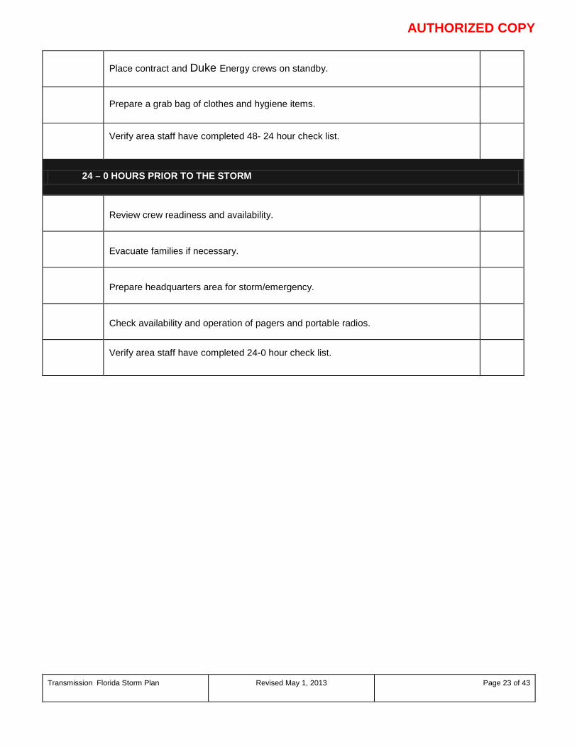
AUTHORIZED COPY
Transmission Florida Storm Plan Revised May 1, 2013
Page 23 of 43
Place contract and Duke Energy crews on standby.
Prepare a grab bag of clothes and hygiene items.
Verify area staff have completed 48- 24 hour check list.
24 – 0 HOURS PRIOR TO THE STORM
Review crew readiness and availability.
Evacuate families if necessary.
Prepare headquarters area for storm/emergency.
Check availability and operation of pagers and portable radios.
Verify area staff have completed 24-0 hour check list.
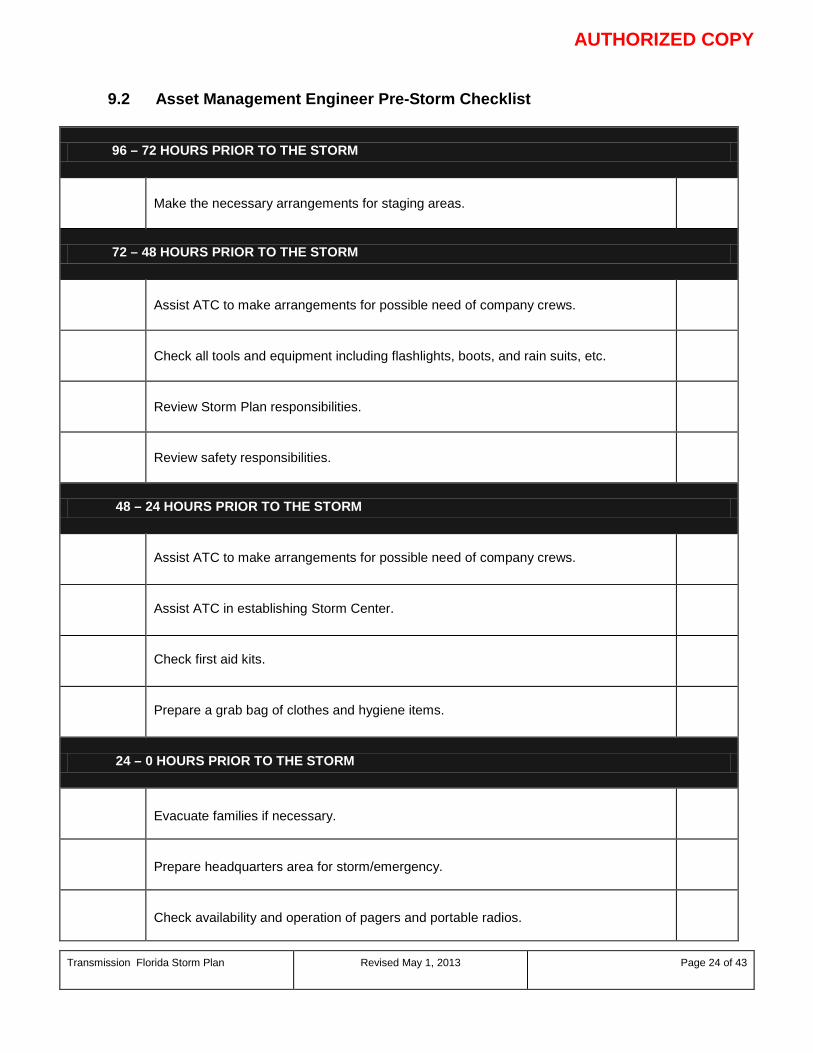
AUTHORIZED COPY
Transmission Florida Storm Plan Revised May 1, 2013
Page 24 of 43
9.2 Asset Management Engineer Pre-Storm Checklist
96 – 72 HOURS PRIOR TO THE STORM
Make the necessary arrangements for staging areas.
72 – 48 HOURS PRIOR TO THE STORM
Assist ATC to make arrangements for possible need of company crews.
Check all tools and equipment including flashlights, boots, and rain suits, etc.
Review Storm Plan responsibilities.
Review safety responsibilities.
48 – 24 HOURS PRIOR TO THE STORM
Assist ATC to make arrangements for possible need of company crews.
Assist ATC in establishing Storm Center.
Check first aid kits.
Prepare a grab bag of clothes and hygiene items.
24 – 0 HOURS PRIOR TO THE STORM
Evacuate families if necessary.
Prepare headquarters area for storm/emergency.
Check availability and operation of pagers and portable radios.

AUTHORIZED COPY
Transmission Florida Storm Plan Revised May 1, 2013
Page 25 of 43
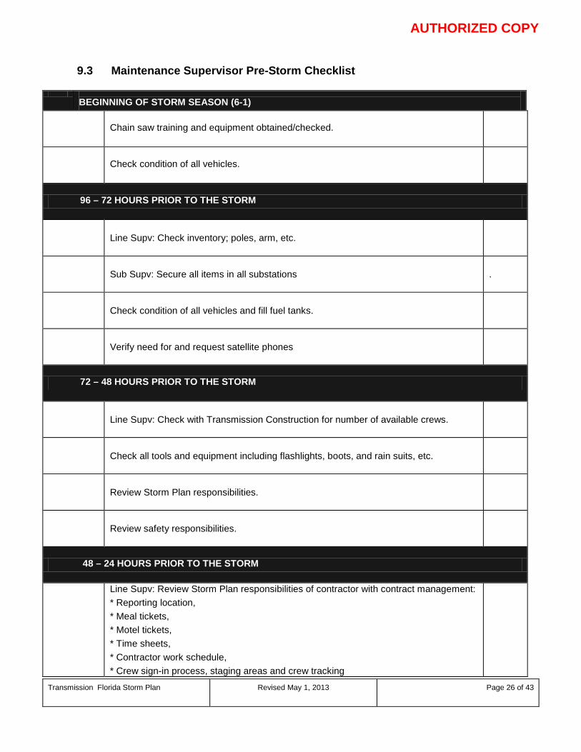
AUTHORIZED COPY
Transmission Florida Storm Plan Revised May 1, 2013
Page 26 of 43
9.3 Maintenance Supervisor Pre-Storm Checklist
BEGINNING OF STORM SEASON (6-1)
Chain saw training and equipment obtained/checked.
Check condition of all vehicles.
96 – 72 HOURS PRIOR TO THE STORM
Line Supv: Check inventory; poles, arm, etc.
Sub Supv: Secure all items in all substations .
Check condition of all vehicles and fill fuel tanks.
Verify need for and request satellite phones
72 – 48 HOURS PRIOR TO THE STORM
Line Supv: Check with Transmission Construction for number of available crews.
Check all tools and equipment including flashlights, boots, and rain suits, etc.
Review Storm Plan responsibilities.
Review safety responsibilities.
48 – 24 HOURS PRIOR TO THE STORM
Line Supv: Review Storm Plan responsibilities of contractor with contract management: * Reporting location, * Meal tickets, * Motel tickets, * Time sheets, * Contractor work schedule, * Crew sign-in process, staging areas and crew tracking
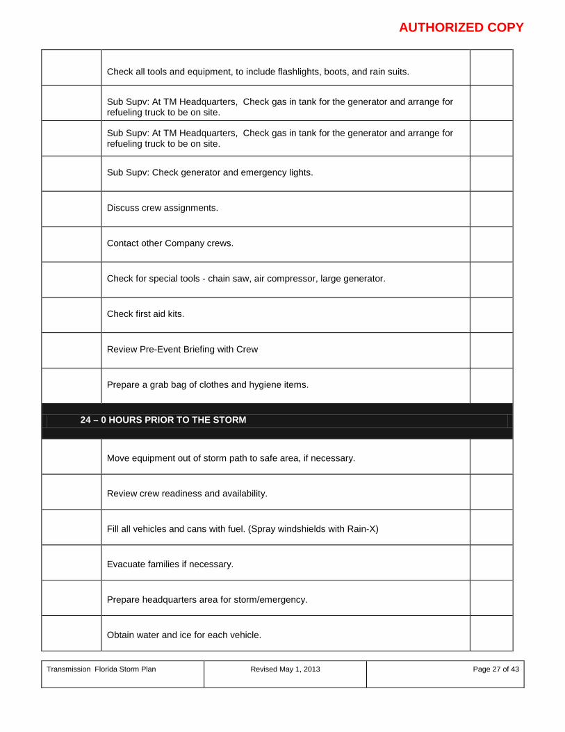
AUTHORIZED COPY
Transmission Florida Storm Plan Revised May 1, 2013
Page 27 of 43
Check all tools and equipment, to include flashlights, boots, and rain suits.
Sub Supv: At TM Headquarters, Check gas in tank for the generator and arrange for refueling truck to be on site.
Sub Supv: At TM Headquarters, Check gas in tank for the generator and arrange for refueling truck to be on site.
Sub Supv: Check generator and emergency lights.
Discuss crew assignments.
Contact other Company crews.
Check for special tools - chain saw, air compressor, large generator.
Check first aid kits.
Review Pre-Event Briefing with Crew
Prepare a grab bag of clothes and hygiene items.
24 – 0 HOURS PRIOR TO THE STORM
Move equipment out of storm path to safe area, if necessary.
Review crew readiness and availability.
Fill all vehicles and cans with fuel. (Spray windshields with Rain-X)
Evacuate families if necessary.
Prepare headquarters area for storm/emergency.
Obtain water and ice for each vehicle.
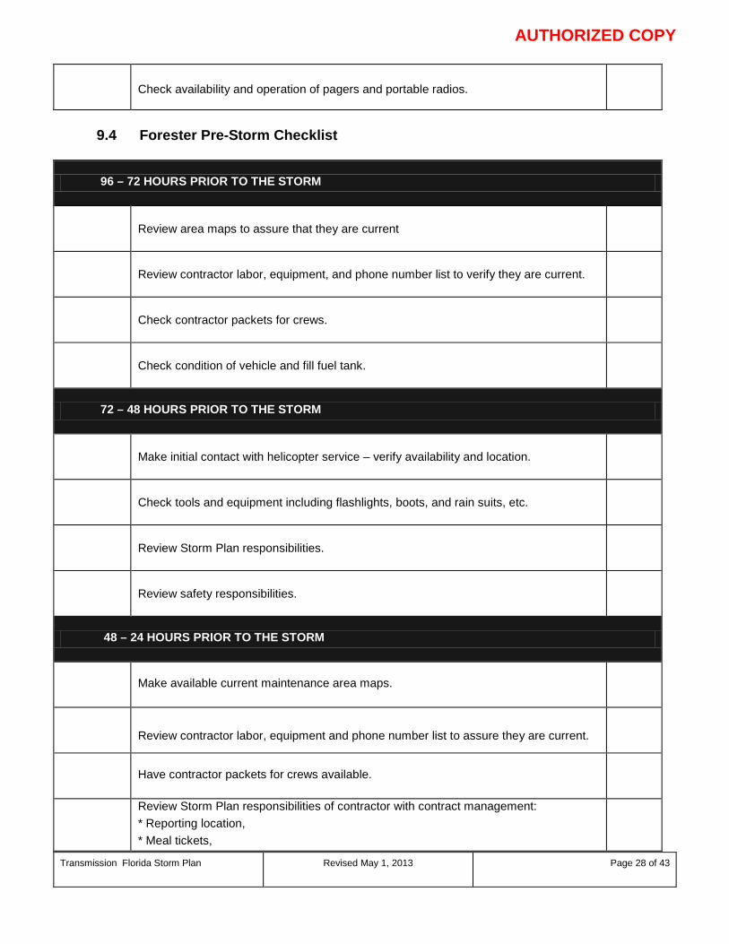
AUTHORIZED COPY
Transmission Florida Storm Plan Revised May 1, 2013
Page 28 of 43
Check availability and operation of pagers and portable radios.
9.4 Forester Pre-Storm Checklist
96 – 72 HOURS PRIOR TO THE STORM
Review area maps to assure that they are current
Review contractor labor, equipment, and phone number list to verify they are current.
Check contractor packets for crews.
Check condition of vehicle and fill fuel tank.
72 – 48 HOURS PRIOR TO THE STORM
Make initial contact with helicopter service – verify availability and location.
Check tools and equipment including flashlights, boots, and rain suits, etc.
Review Storm Plan responsibilities.
Review safety responsibilities.
48 – 24 HOURS PRIOR TO THE STORM
Make available current maintenance area maps.
Review contractor labor, equipment and phone number list to assure they are current.
Have contractor packets for crews available.
Review Storm Plan responsibilities of contractor with contract management: * Reporting location, * Meal tickets,
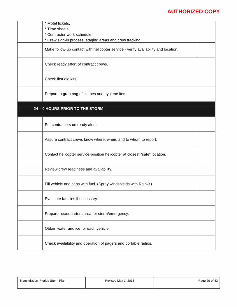
AUTHORIZED COPY
Transmission Florida Storm Plan Revised May 1, 2013
Page 29 of 43
* Motel tickets, * Time sheets, * Contractor work schedule, * Crew sign-in process, staging areas and crew tracking
Make follow-up contact with helicopter service - verify availability and location.
Check ready effort of contract crews.
Check first aid kits.
Prepare a grab bag of clothes and hygiene items.
24 – 0 HOURS PRIOR TO THE STORM
Put contractors on ready alert.
Assure contract crews know where, when, and to whom to report.
Contact helicopter service-position helicopter at closest "safe" location.
Review crew readiness and availability.
Fill vehicle and cans with fuel. (Spray windshields with Rain-X)
Evacuate families if necessary.
Prepare headquarters area for storm/emergency.
Obtain water and ice for each vehicle.
Check availability and operation of pagers and portable radios.

AUTHORIZED COPY
Transmission Florida Storm Plan Revised May 1, 2013
Page 30 of 43
9.5 Administrative Assistant Pre-Storm Checklist
BEGINNING OF STORM SEASON (6-1)
Verify and distribute updated Storm Plan organizational charts, phone lists, and identify where to find those.
96 – 72 HOURS PRIOR TO THE STORM
Contact Facilities Management to check gas in the tank for the local generator(s).
Check ice machine to see if ice is needed. Contact local ice company if needed.
72 – 48 HOURS PRIOR TO THE STORM
Review Storm Plan responsibilities.
Review safety responsibilities.
48 – 24 HOURS PRIOR TO THE STORM
Ask for additional portable cell phones and hand held radios and distribute.
Stock food and water at headquarters; order port-a-johns.
Check all tools and equipment, to include flashlights, boots, and rain suits.
Assist ATC in establishing Storm Center.
Prepare a grab bag of clothes and hygiene items.
Contact District Coordinator to reserve hotel rooms.
Contact District Coordinator regarding meals for crews.
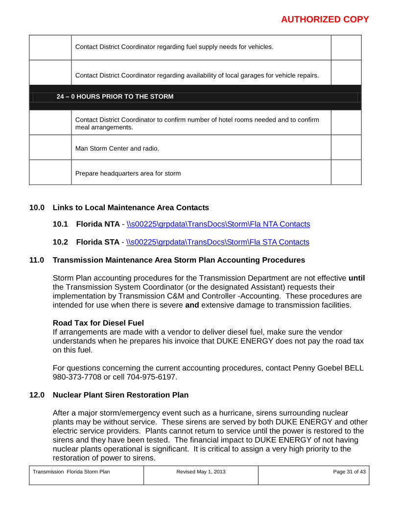
AUTHORIZED COPY
Transmission Florida Storm Plan Revised May 1, 2013
Page 31 of 43
Contact District Coordinator regarding fuel supply needs for vehicles.
Contact District Coordinator regarding availability of local garages for vehicle repairs.
24 – 0 HOURS PRIOR TO THE STORM
Contact District Coordinator to confirm number of hotel rooms needed and to confirm meal arrangements.
Man Storm Center and radio.
Prepare headquarters area for storm
10.0 Links to Local Maintenance Area Contacts
10.1 Florida NTA - \\s00225\grpdata\TransDocs\Storm\Fla NTA Contacts 10.2 Florida STA - \\s00225\grpdata\TransDocs\Storm\Fla STA Contacts
11.0 Transmission Maintenance Area Storm Plan Accounting Procedures
Storm Plan accounting procedures for the Transmission Department are not effective until the Transmission System Coordinator (or the designated Assistant) requests their implementation by Transmission C&M and Controller -Accounting. These procedures are intended for use when there is severe and extensive damage to transmission facilities. Road Tax for Diesel Fuel If arrangements are made with a vendor to deliver diesel fuel, make sure the vendor understands when he prepares his invoice that DUKE ENERGY does not pay the road tax on this fuel. For questions concerning the current accounting procedures, contact Penny Goebel BELL 980-373-7708 or cell 704-975-6197.
12.0 Nuclear Plant Siren Restoration Plan
After a major storm/emergency event such as a hurricane, sirens surrounding nuclear plants may be without service. These sirens are served by both DUKE ENERGY and other electric service providers. Plants cannot return to service until the power is restored to the sirens and they have been tested. The financial impact to DUKE ENERGY of not having nuclear plants operational is significant. It is critical to assign a very high priority to the restoration of power to sirens.
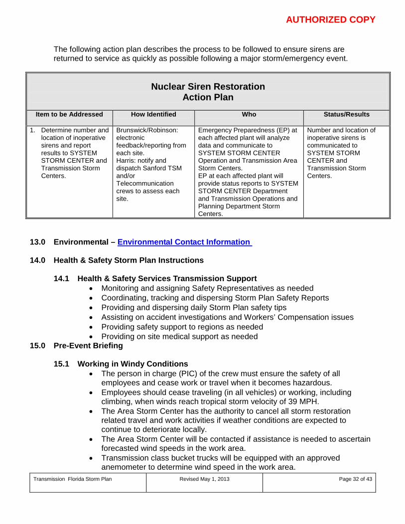
AUTHORIZED COPY
Transmission Florida Storm Plan Revised May 1, 2013
Page 32 of 43
The following action plan describes the process to be followed to ensure sirens are returned to service as quickly as possible following a major storm/emergency event.
Nuclear Siren Restoration Action Plan
Item to be Addressed How Identified Who
Status/Results
1. Determine number and location of inoperative sirens and report results to SYSTEM STORM CENTER and Transmission Storm Centers.
Brunswick/Robinson: electronic feedback/reporting from each site. Harris: notify and dispatch Sanford TSM and/or Telecommunication crews to assess each site.
Emergency Preparedness (EP) at each affected plant will analyze data and communicate to SYSTEM STORM CENTER Operation and Transmission Area Storm Centers. EP at each affected plant will provide status reports to SYSTEM STORM CENTER Department and Transmission Operations and Planning Department Storm Centers.
Number and location of inoperative sirens is communicated to SYSTEM STORM CENTER and Transmission Storm Centers.
13.0 Environmental – Environmental Contact Information 14.0 Health & Safety Storm Plan Instructions
14.1 Health & Safety Services Transmission Support • Monitoring and assigning Safety Representatives as needed • Coordinating, tracking and dispersing Storm Plan Safety Reports • Providing and dispersing daily Storm Plan safety tips • Assisting on accident investigations and Workers’ Compensation issues • Providing safety support to regions as needed • Providing on site medical support as needed
15.0 Pre-Event Briefing
15.1 Working in Windy Conditions • The person in charge (PIC) of the crew must ensure the safety of all
employees and cease work or travel when it becomes hazardous. • Employees should cease traveling (in all vehicles) or working, including
climbing, when winds reach tropical storm velocity of 39 MPH. • The Area Storm Center has the authority to cancel all storm restoration
related travel and work activities if weather conditions are expected to continue to deteriorate locally.
• The Area Storm Center will be contacted if assistance is needed to ascertain forecasted wind speeds in the work area.
• Transmission class bucket trucks will be equipped with an approved anemometer to determine wind speed in the work area.

AUTHORIZED COPY
Transmission Florida Storm Plan Revised May 1, 2013
Page 33 of 43
15.2 Use of Transmission Class Bucket Trucks in Windy Conditions
• Employees are prohibited from operating bucket trucks in the elevated work position when the wind speed (steady or gusts) exceeds 30 MPH.
• Any manufacture's recommended wind speed guideline, for bucket trucks operating in the elevated position, which is less than 30 MPH must be adhered to for said equipment. (Example: Condor (Transmission) recommends a maximum wind speed of 25 MPH.)
• The wind speed must be determined by using an approved anemometer before vehicles equipped with an aerial lift device are operated in the elevated work position.
• The wind speed must be periodically tested with an approved anemometer at the work elevation throughout the work process if windy conditions are present in the work area.
• When operating in winds up to, but not exceeding 30 MPH, follow these precautions: o Outriggers, if so equipped, must be properly extended and on firm ground.
Always use outrigger pads if there is any doubt as to the ground firmness. o On units without outriggers, the tires must be properly inflated and on firm
ground. The truck must be maintained at a safe angle as described in the operator’s manual.
o Refer to specific equipment operator / instruction manual for other precautions.
15.3 Work Coordination
• Coordination of Personnel: Field personnel will be dispatched by the local
area storm centers and will contact the ECC/DCC upon arrival at the work site.
• Hours of Work: The hours of work will be determined by the local area storm center. In general each person is permitted to initially work a maximum of 25 continuous hours before being rested. All hours should be counted once a person reports for work, including travel time to and from the job site. The hours that should be counted should also include breaks and rest periods that are less than eight hours in length. After the initial work period, the employee should be allowed to rest a minimum of 8 hours before returning to work. After the initial work period, employees should be limited to a maximum of 16 hours for each work period. In general, personnel are more productive in daylight hours and the majority of field personnel should have their hours scheduled in daylight.
• Special Circumstances: If special circumstances dictate that a major objective can be achieved by working an additional three hours or less, this will be allowed only if authorized through the local area storm center. Any personnel working more than 28 hours should have approval from the Transmission System Storm Coordinator.
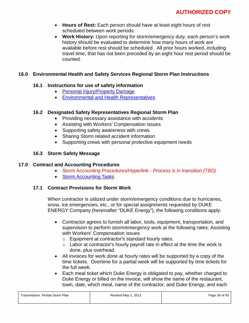
AUTHORIZED COPY
Transmission Florida Storm Plan Revised May 1, 2013
Page 34 of 43
• Hours of Rest: Each person should have at least eight hours of rest scheduled between work periods.
• Work History: Upon reporting for storm/emergency duty, each person’s work history should be evaluated to determine how many hours of work are available before rest should be scheduled. All prior hours worked, including travel time, that has not been preceded by an eight hour rest period should be counted.
16.0 Environmental Health and Safety Services Regional Storm Plan Instructions
16.1 Instructions for use of safety information • Personal Injury/Property Damage • Environmental and Health Representatives
16.2 Designated Safety Representatives Regional Storm Plan • Providing necessary assistance with accidents • Assisting with Workers’ Compensation issues • Supporting safety awareness with crews • Sharing Storm related accident information • Supporting crews with personal protective equipment needs
16.3 Storm Safety Message 17.0 Contract and Accounting Procedures
• Storm Accounting Procedures/Hyperlink - Process is in transition (TBD) • Storm Accounting Tasks
17.1 Contract Provisions for Storm Work
When contractor is utilized under storm/emergency conditions due to hurricanes, snow, ice emergencies, etc., or for special assignments requested by DUKE ENERGY Company (hereinafter “DUKE Energy”), the following conditions apply:
• Contractor agrees to furnish all labor, tools, equipment, transportation, and supervision to perform storm/emergency work at the following rates: Assisting with Workers’ Compensation issues o Equipment at contractor's standard hourly rates. o Labor at contractor's hourly payroll rate in effect at the time the work is
done, plus overhead. • All invoices for work done at hourly rates will be supported by a copy of the
time tickets. Overtime for a partial week will be supported by time tickets for the full week.
• Each meal ticket which Duke Energy is obligated to pay, whether charged to Duke Energy or billed on the invoice, will show the name of the restaurant, town, date, which meal, name of the contractor, and Duke Energy, and each
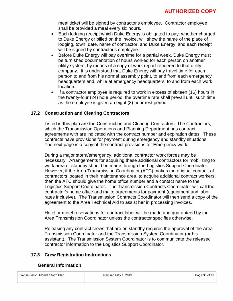
AUTHORIZED COPY
Transmission Florida Storm Plan Revised May 1, 2013
Page 35 of 43
meal ticket will be signed by contractor's employee. Contractor employee shall be provided a meal every six hours.
• Each lodging receipt which Duke Energy is obligated to pay, whether charged to Duke Energy or billed on the invoice, will show the name of the place of lodging, town, date, name of contractor, and Duke Energy, and each receipt will be signed by contractor's employee.
• Before Duke Energy will pay overtime for a partial week, Duke Energy must be furnished documentation of hours worked for each person on another utility system, by means of a copy of work report rendered to that utility company. It is understood that Duke Energy will pay travel time for each person to and from his normal assembly point, to and from each emergency headquarters and, while at emergency headquarters, to and from each work location.
• If a contractor employee is required to work in excess of sixteen (16) hours in the twenty-four (24) hour period, the overtime rate shall prevail until such time as the employee is given an eight (8) hour rest period.
17.2 Construction and Clearing Contractors
Listed in this plan are the Construction and Clearing Contractors. The Contractors, which the Transmission Operations and Planning Department has contract agreements with are indicated with the contract number and expiration dates. These contracts have provisions for payment during emergency and standby situations. The next page is a copy of the contract provisions for Emergency work. During a major storm/emergency, additional contractor work forces may be necessary. Arrangements for acquiring these additional contractors for mobilizing to work area or standby should be made through the Logistics Support Coordinator. However, if the Area Transmission Coordinator (ATC) makes the original contact, of contractors located in their maintenance area, to acquire additional contract workers, then the ATC should give the home office number and a contact name to the Logistics Support Coordinator. The Transmission Contracts Coordinator will call the contractor's home office and make agreements for payment (equipment and labor rates inclusive). The Transmission Contracts Coordinator will then send a copy of the agreement to the Area Technical Aid to assist her in processing invoices. Hotel or motel reservations for contract labor will be made and guaranteed by the Area Transmission Coordinator unless the contractor specifies otherwise. Releasing any contract crews that are on standby requires the approval of the Area Transmission Coordinator and the Transmission System Coordinator (or his assistant). The Transmission System Coordinator is to communicate the released contractor information to the Logistics Support Coordinator.
17.3 Crew Registration Instructions
General Information
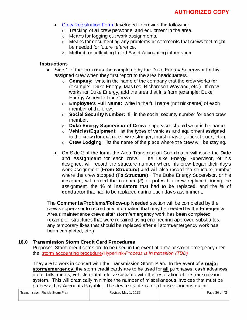
AUTHORIZED COPY
Transmission Florida Storm Plan Revised May 1, 2013
Page 36 of 43
• Crew Registration Form developed to provide the following: o Tracking of all crew personnel and equipment in the area. o Means for logging out work assignments. o Means for documenting any problems or comments that crews feel might
be needed for future reference. o Method for collecting Fixed Asset Accounting information.
Instructions
• Side 1 of the form must be completed by the Duke Energy Supervisor for his assigned crew when they first report to the area headquarters.
o Company: write in the name of the company that the crew works for (example: Duke Energy, MasTec, Richardson Wayland, etc.). If crew works for Duke Energy, add the area that it is from (example: Duke Energy Asheville Line Crew).
o Employee's Full Name: write in the full name (not nickname) of each member of the crew.
o Social Security Number: fill in the social security number for each crew member.
o Duke Energy Supervisor of Crew: supervisor should write in his name. o Vehicles/Equipment: list the types of vehicles and equipment assigned
to the crew (for example: wire stringer, marsh master, bucket truck, etc.). o Crew Lodging: list the name of the place where the crew will be staying.
• On Side 2 of the form, the Area Transmission Coordinator will issue the Date
and Assignment for each crew. The Duke Energy Supervisor, or his designee, will record the structure number where his crew began their day's work assignment (From Structure) and will also record the structure number where the crew stopped (To Structure). The Duke Energy Supervisor, or his designee, will record the number (#) of poles his crew replaced during the assignment, the % of insulators that had to be replaced, and the % of conductor that had to be replaced during each day's assignment.
The Comments/Problems/Follow-up Needed section will be completed by the crew's supervisor to record any information that may be needed by the Emergency Area's maintenance crews after storm/emergency work has been completed (example: structures that were repaired using engineering-approved substitutes, any temporary fixes that should be replaced after all storm/emergency work has been completed, etc.)
18.0 Transmission Storm Credit Card Procedures Purpose: Storm credit cards are to be used in the event of a major storm/emergency (per
the storm accounting procedure/Hyperlink-Process is in transition (TBD)
They are to work in concert with the Transmission Storm Plan. In the event of a major storm/emergency, the storm credit cards are to be used for all purchases, cash advances, motel bills, meals, vehicle rental, etc. associated with the restoration of the transmission system. This will drastically minimize the number of miscellaneous invoices that must be processed by Accounts Payable. The desired state is for all miscellaneous major
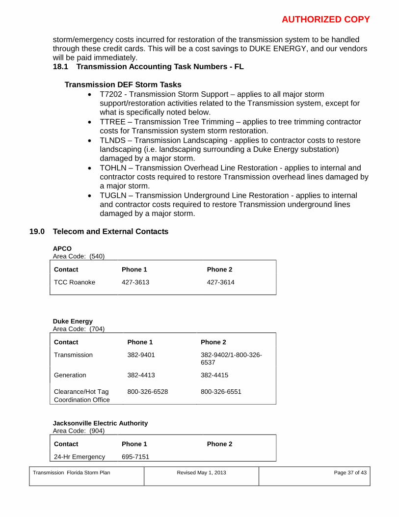
AUTHORIZED COPY
Transmission Florida Storm Plan Revised May 1, 2013
Page 37 of 43
storm/emergency costs incurred for restoration of the transmission system to be handled through these credit cards. This will be a cost savings to DUKE ENERGY, and our vendors will be paid immediately. 18.1 Transmission Accounting Task Numbers - FL
Transmission DEF Storm Tasks • T7202 - Transmission Storm Support – applies to all major storm
support/restoration activities related to the Transmission system, except for what is specifically noted below.
• TTREE – Transmission Tree Trimming – applies to tree trimming contractor costs for Transmission system storm restoration.
• TLNDS – Transmission Landscaping - applies to contractor costs to restore landscaping (i.e. landscaping surrounding a Duke Energy substation) damaged by a major storm.
• TOHLN – Transmission Overhead Line Restoration - applies to internal and contractor costs required to restore Transmission overhead lines damaged by a major storm.
• TUGLN – Transmission Underground Line Restoration - applies to internal and contractor costs required to restore Transmission underground lines damaged by a major storm.
19.0 Telecom and External Contacts
APCO Area Code: (540) Contact
Phone 1
Phone 2
TCC Roanoke
427-3613
427-3614
Duke Energy Area Code: (704) Contact
Phone 1
Phone 2
Transmission
382-9401
382-9402/1-800-326-6537
Generation
382-4413
382-4415
Clearance/Hot Tag Coordination Office
800-326-6528
800-326-6551
Jacksonville Electric Authority Area Code: (904) Contact
Phone 1
Phone 2
24-Hr Emergency
695-7151
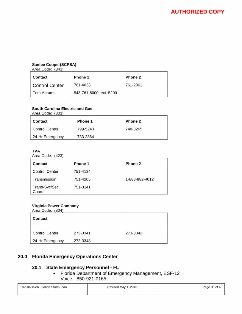
AUTHORIZED COPY
Transmission Florida Storm Plan Revised May 1, 2013
Page 38 of 43
Santee Cooper(SCPSA) Area Code: (843) Contact
Phone 1
Phone 2
Control Center
761-4033
761-2961
Tom Abrams 843-761-8000, ext. 5200
South Carolina Electric and Gas Area Code: (803) Contact
Phone 1
Phone 2
Control Center
799-5243
748-3265
24-Hr Emergency
733-2864
TVA Area Code: (423) Contact
Phone 1
Phone 2
Control Center
751-4134
Transmission
751-4205
1-888-882-4012
Trans-Svc/Sec Coord
751-3141
Virginia Power Company Area Code: (804) Contact
Control Center
273-3341
273-3342
24-Hr Emergency
273-3348
20.0 Florida Emergency Operations Center
20.1 State Emergency Personnel - FL • Florida Department of Emergency Management, ESF-12
Voice: 850-921-0165
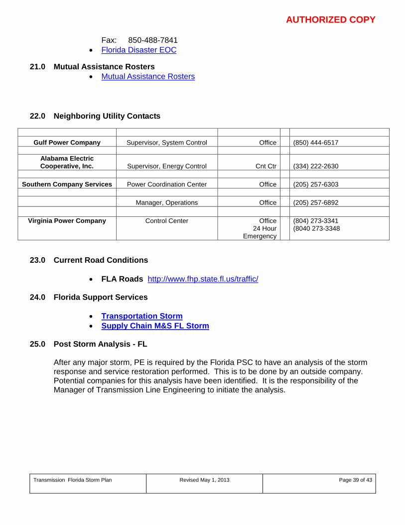
AUTHORIZED COPY
Transmission Florida Storm Plan Revised May 1, 2013
Page 39 of 43
Fax: 850-488-7841 • Florida Disaster EOC
21.0 Mutual Assistance Rosters
• Mutual Assistance Rosters 22.0 Neighboring Utility Contacts
Gulf Power Company Supervisor, System Control Office (850) 444-6517
Alabama Electric Cooperative, Inc. Supervisor, Energy Control Cnt Ctr (334) 222-2630
Southern Company Services Power Coordination Center Office (205) 257-6303
Manager, Operations Office (205) 257-6892
Virginia Power Company Control Center Office 24 Hour
Emergency
(804) 273-3341 (8040 273-3348
23.0 Current Road Conditions
• FLA Roads http://www.fhp.state.fl.us/traffic/ 24.0 Florida Support Services
• Transportation Storm • Supply Chain M&S FL Storm
25.0 Post Storm Analysis - FL
After any major storm, PE is required by the Florida PSC to have an analysis of the storm response and service restoration performed. This is to be done by an outside company. Potential companies for this analysis have been identified. It is the responsibility of the Manager of Transmission Line Engineering to initiate the analysis.
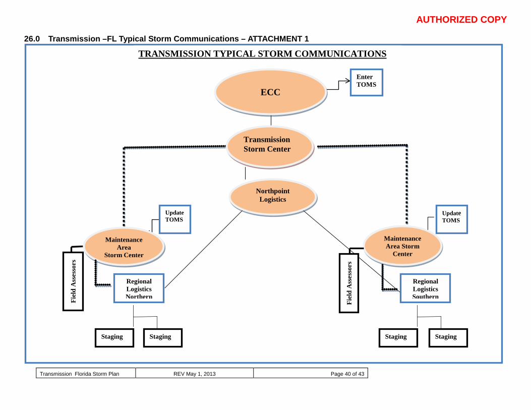
AUTHORIZED COPY
Transmission Florida Storm Plan REV May 1, 2013 Page 40 of 43
26.0 Transmission –FL Typical Storm Communications – ATTACHMENT 1
Update TOMS
Maintenance Area Storm
Center
Regional Logistics Southern
Fiel
d A
sses
sors
Fiel
d A
sses
sors
Update TOMS
Maintenance Area
Storm Center
Regional Logistics Northern
Staging Staging Staging Staging
Northpoint Logistics
Enter TOMS
Transmission Storm Center
ECC
TRANSMISSION TYPICAL STORM COMMUNICATIONS
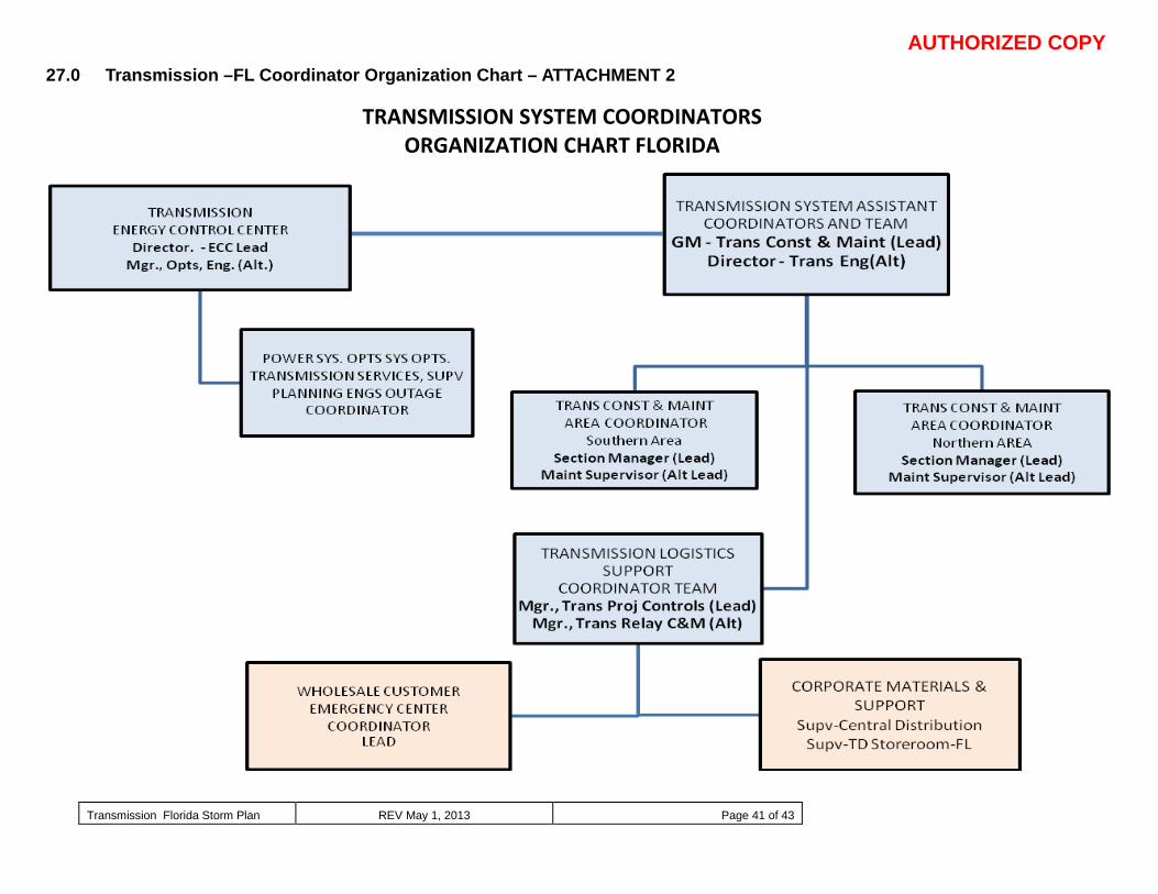
AUTHORIZED COPY
Transmission Florida Storm Plan REV May 1, 2013 Page 41 of 43
27.0 Transmission –FL Coordinator Organization Chart – ATTACHMENT 2
TRANSMISSION SYSTEM COORDINATORS ORGANIZATION CHART FLORIDA
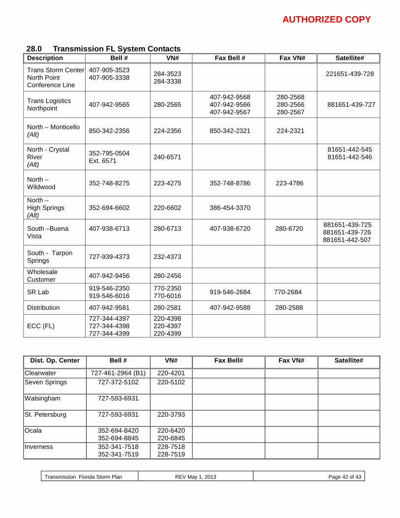
AUTHORIZED COPY
Transmission Florida Storm Plan REV May 1, 2013 Page 42 of 43
28.0 Transmission FL System Contacts Description Bell # VN# Fax Bell # Fax VN# Satellite#
Trans Storm Center North Point Conference Line
407-905-3523 407-905-3338
284-3523 284-3338 221651-439-728
Trans Logistics Northpoint 407-942-9565 280-2565
407-942-9568 407-942-9566 407-942-9567
280-2568 280-2566 280-2567
881651-439-727
North – Monticello (Alt) 850-342-2356 224-2356 850-342-2321 224-2321
North - Crystal River (Alt)
352-795-0504 Ext. 6571 240-6571
81651-442-545 81651-442-546
North – Wildwood 352-748-8275 223-4275 352-748-8786 223-4786
North – High Springs (Alt)
352-694-6602 220-6602 386-454-3370
South –Buena Vista
407-938-6713
280-6713
407-938-6720
280-6720
881651-439-725 881651-439-726 881651-442-507
South - Tarpon Springs 727-939-4373 232-4373
Wholesale Customer 407-942-9456 280-2456
SR Lab 919-546-2350 919-546-6016
770-2350 770-6016 919-546-2684 770-2684
Distribution 407-942-9581 280-2581 407-942-9588 280-2588
ECC (FL) 727-344-4397 727-344-4398 727-344-4399
220-4398 220-4397 220-4399
Dist. Op. Center Bell # VN# Fax Bell# Fax VN# Satellite#
Clearwater 727-461-2964 (B1) 220-4201 Seven Springs 727-372-5102
220-5102
Walsingham 727-593-6931
St. Petersburg 727-593-6931 220-3793
Ocala 352-694-8420 352-694-8845
220-6420 220-6845
Inverness 352-341-7518 352-341-7519
228-7518 228-7519
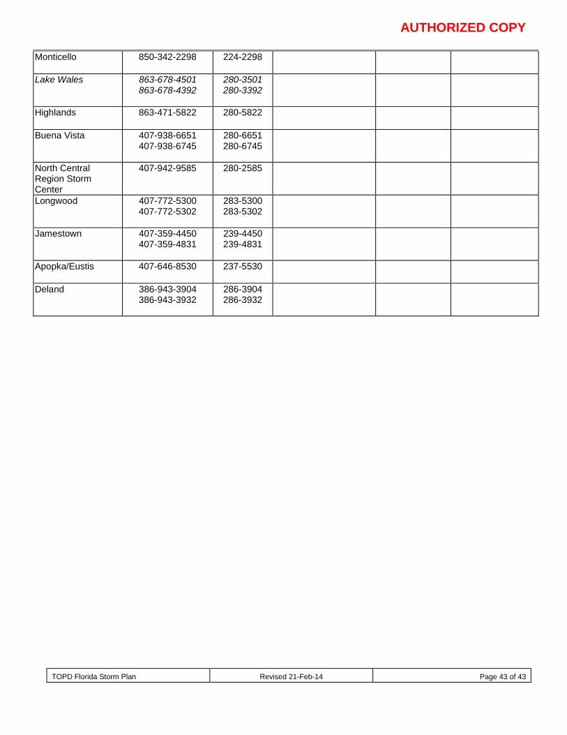
AUTHORIZED COPY
TOPD Florida Storm Plan Revised 21-Feb-14 Page 43 of 43
Monticello 850-342-2298
224-2298
Lake Wales 863-678-4501 863-678-4392
280-3501 280-3392
Highlands 863-471-5822
280-5822
Buena Vista 407-938-6651 407-938-6745
280-6651 280-6745
North Central Region Storm Center
407-942-9585
280-2585
Longwood 407-772-5300 407-772-5302
283-5300 283-5302
Jamestown 407-359-4450 407-359-4831
239-4450 239-4831
Apopka/Eustis 407-646-8530
237-5530
Deland 386-943-3904 386-943-3932
286-3904 286-3932
Related Documents


