Service Manual Part No. 84700 Rev C1 January 2011 from GR05-5001 Serial Number Range from GR05-5001 from GR05-5001 GR -12 GR -15 GR -20 from QS09-101 from QS09-101 from QS09-101 QS-12R QS-15R QS-20R from QS09-101 from QS09-101 from QS09-101 QS-12W QS-15W QS-20W

Welcome message from author
This document is posted to help you gain knowledge. Please leave a comment to let me know what you think about it! Share it to your friends and learn new things together.
Transcript

Service Manual
Part No. 84700
Rev C1
January 2011
from GR05-5001
Serial Number Range
from GR05-5001
from GR05-5001
GR -12
GR -15
GR -20
from QS09-101
from QS09-101
from QS09-101
QS-12R
QS-15R
QS-20R
from QS09-101
from QS09-101
from QS09-101
QS-12W
QS-15W
QS-20W

January 2011
GR-12 • GR-15 • GR-20 Part No. 84700ii
Important
Read, understand and obey the safety rules andoperating instructions in the appropriate Operator'sManual on your machine before attempting anymaintenance procedure.
Basic mechanical, hydraulic and electricalskills are required to perform most procedures.However, several procedures require specializedskills, tools, lifting equipment and a suitableworkshop. In these instances, we stronglyrecommend that maintenance and repair beperformed at an authorized Genie dealerservice center.
Compliance
Machine ClassificationGroup A/Type 2,3 as defined by ISO 16368
Machine Design LifeUnrestricted with proper opeation, inspection andscheduled maintenance.
Technical Publications
Genie Industries has endeavored to deliver thehighest degree of accuracy possible. However,continuous improvement of our products is a Geniepolicy. Therefore, product specificationsare subject to change without notice.
Readers are encouraged to notify Genie of errorsand send in suggestions for improvement. Allcommunications will be carefully considered forfuture printings of this and all other manuals.
Contact Us:
www.genieindustries.come-mail: [email protected]
Copyright © 2001 by Genie Industries
84700 Rev C September 2009Second Edition, Third Printing
"Genie" is a registered trademark of GenieIndustries in the USA and many other countries."GR" is a trademark of Genie Industries.
Printed on recycled paper
Printed in U.S.A.
Serial Number Information
Genie Industries offers the following ServiceManuals for these models:
Title Part No.
Genie Runabout Service Manual,First Edition(before serial number GR05-5001) ....................... 72965
Introduction

September 2009
Part No. 84700 GR • QSR • QSW
Serial Number Legend
iii
INTRODUCTION
GR 05 - 12345
Model Sequencenumber
Model year
GR(serial number stamp)
Serial label
MANUFACTURED BY/FABRIQUE PAR:Genie Industries18340 NE 76th StreetRedmond, WA 98052 USA
Model: GR-15Serial number: GR05-1234Model year:2008 Manufacture date:Elec/Hydr Schematic:Power supply voltage/Pneumatic Pressure:
85-264 VAC, 60/50 Hz, 900 WNominal Power: 8.3 Hp / 6.2 kWMachine unladen weight: 2,250 lbs / 1,021 kg
4/14/08ES0126/HS0039
Max Load: 500 lbs / 227 kgOccupants and Equipment must not exceed:
500 lbs / 227 kgMaximum allowable inclination of the chassis:
1.5°(Side) 3°(Front) 3°(Rear)Maximum Wind Speed:
Indoor:Outdoor:
28 mph / 12.5 m/s28 mph / 12.5 m/s
Gradeability: 30%Maximum allowable side force: 100 lbs / 445 NMaximum platform height: 14 ft 8 in / 4.47 mMaximum Travel Height: Full htMaximum number of platform occupants: 1Country of manufacture: USAThis machine complies with:
EN 28098/37/EC
PN- 7717207
QSR/QSW(serial number stamp)

September 2009
GR • QSR • QSW Part No. 84700
This page intentionally left blank.
iv

September 2009
Part No. 84700 GR • QSR • QSW v
DangerFailure to obey the instructions and safety rulesin this manual and the appropriate Operator'sManual on your machine will result in death orserious injury.
Many of the hazards identified in theoperator’s manual are also safety hazardswhen maintenance and repair proceduresare performed.
Do Not Perform MaintenanceUnless:
You are trained and qualified to performmaintenance on this machine.
You read, understand and obey:- manufacturer’s instructions and safety rules- employer’s safety rules and worksite
regulations- applicable governmental regulations
You have the appropriate tools, liftingequipment and a suitable workshop.
Safety Rules

September 2009
GR • QSR • QSW Part No. 84700
SAFETY RULES
vi
Workplace SafetyBe sure to keep sparks, flames andlighted tobacco away from flammable andcombustible materials like battery gases
and engine fuels. Always have an approved fireextinguisher within easy reach.
Be sure that all tools and working areasare properly maintained and ready foruse. Keep work surfaces clean and free of
debris that could get into machine components andcause damage.
Be sure any forklift, overhead crane orother lifting or supporting device is fullycapable of supporting and stabilizing the
weight to be lifted. Use only chains or straps thatare in good condition and of ample capacity.
Be sure that fasteners intended for onetime use (i.e., cotter pins and self-lockingnuts) are not reused. These components
may fail if they are used a second time.
Be sure to properly dispose of old oil orother fluids. Use an approved container.Please be environmentally safe .
Be sure that your workshop or work areais properly ventilated and well lit.
Personal SafetyAny person working on or around a machine mustbe aware of all known safety hazards. Personalsafety and the continued safe operation of themachine should be your top priority.
Read each procedure thoroughly. Thismanual and the decals on the machine,use signal words to identify the following:
Safety alert symbol—used to alertpersonnel to potential personalinjury hazards. Obey all safetymessages that follow this symbolto avoid possible injury or death.
Indicates an imminently hazardoussituation which, if not avoided, willresult in death or serious injury.
Indicates a potentially hazardoussituation which, if not avoided,could result in death or seriousinjury.
Indicates a potentially hazardoussituation which, if not avoided,may cause minor or moderateinjury.
Indicates a potentially hazardoussituation which, if not avoided,may result in property damage.
Be sure to wear protective eye wear andother protective clothing if the situationwarrants it.
Be aware of potential crushing hazardssuch as moving parts, free swinging orunsecured components when lifting or
placing loads. Always wear approved steel-toedshoes.

September 2009
Part No. 84700 GR • QSR • QSW
Table of Contents
Introduction
Important Information ......................................................................................... ii
Serial Number Information ................................................................................. ii
Serial Number Legend ...................................................................................... iii
Section 1 Safety Rules
General Safety Rules ........................................................................................ v
Section 2 Rev Specifications
D Machine Specifications ................................................................................ 2 - 1
Performance Specifications ......................................................................... 2 - 2
Hydraulic Specifications ............................................................................... 2 - 3
Manifold Component Specifications ............................................................. 2 - 4
Hydraulic Hose and Fitting Torque Specifications ........................................ 2 - 5
SAE and Metric Fasteners Torque Charts ................................................... 2 - 7
Section 3 Rev Scheduled Maintenance Procedures
Introduction .................................................................................................. 3 - 1
Pre-delivery Preparation Report .................................................................. 3 - 3
Maintenance Inspection Report ................................................................... 3 - 5
D Checklist A Procedures
A-1 Inspect the Manuals and Decals ......................................................... 3 - 6
A-2 Perform Pre-operation Inspection ....................................................... 3 - 7
A-3 Perform Function Tests ...................................................................... 3 - 7
A-4 Test the Obstruction Sensing System (QSR models only) ................. 3 - 8
A-5 Perform 30 Day Service ..................................................................... 3 - 9
A-6 Grease the Steer Yokes ..................................................................... 3 - 9
vii

September 2009
GR • QSR • QSW Part No. 84700
TABLE OF CONTENTS
Section 3 Rev Scheduled Maintenance Procedures, continued
D Checklist B Procedures
B-1 Inspect the Batteries ......................................................................... 3 - 10
B-2 Inspect the Electrical Wiring ............................................................. 3 - 12
B-3 Inspect the Tires and Wheels (including castle nut torque) ............... 3 - 13
B-4 Check the Lifting Chain Adjustments ................................................ 3 - 13
B-5 Clean and Lubricate the Columns..................................................... 3 - 14
B-6 Adjust the Sequencing Cables .......................................................... 3 - 14
B-7 Test the Emergency Stop ................................................................. 3 - 15
B-8 Test the Key Switch .......................................................................... 3 - 16
B-9 Test the Automotive-style Horn (if equipped) .................................... 3 - 16
B-10 Inspect the Voltage Inverter (if equipped) ......................................... 3 - 17
B-11 Test the Drive Brakes ....................................................................... 3 - 18
B-12 Test the Drive Speed - Stowed Position ........................................... 3 - 19
B-13 Test the Drive Speed - Raised Position ............................................ 3 - 20
B-14 Test the Slow Drive Speed ............................................................... 3 - 21
B-15 Test the Motion Alarm (if equipped) .................................................. 3 - 22
B-16 Test the Flashing Beacons (if equipped) .......................................... 3 - 23
B-17 Perform Hydraulic Oil Analysis ......................................................... 3 - 23
B-18 Inspect the Breather Cap .................................................................. 3 - 24
D Checklist C Procedures
C-1 Grease the Platform Overload Mechanism (if equipped) .................. 3 - 25
C-2 Replace the Hydraulic Tank Breather Cap -Models with Optional Hydraulic Oil ................................................... 3 - 25
C-3 Test the Platform Overload System (if equipped) ............................. 3 - 26
D Checklist D Procedures
D-1 Inspect the Mast Assembly for Wear ................................................ 3 - 28
D-2 Inspect and Lubricate the Lifting Chains ........................................... 3 - 29
D-3 Replace the Hydraulic Tank Return Filter ......................................... 3 - 30
B Checklist E Procedure
E-1 Test or Replace the Hydraulic Oil ..................................................... 3 - 31
viii

September 2009
Part No. 84700 GR • QSR • QSW
TABLE OF CONTENTS
Section 4 Rev Repair Procedures
Introduction .................................................................................................. 4 - 1
E Platform Controls
1-1 Circuit Boards .................................................................................... 4 - 2
1-2 Controller Adjustments ....................................................................... 4 - 3
1-3 Software Configuration ....................................................................... 4 - 8
C Platform Components
2-1 Platform ........................................................................................... 4 - 12
2-2 Platform Extension ........................................................................... 4 - 12
2-3 Work Tray ........................................................................................ 4 - 13
B Mast Components
3-1 Mast ................................................................................................. 4 - 14
3-2 Glide Pads ....................................................................................... 4 - 18
3-3 Lifting Chains ................................................................................... 4 - 18
3-4 Lift Cylinder ...................................................................................... 4 - 21
B Ground Controls
4-1 Level Sensor .................................................................................... 4 - 22
A Hydraulic Pump
5-1 Function Pump ................................................................................. 4 - 25
B Function Manifold
6-1 Function Manifold Components ........................................................ 4 - 28
6-2 Valve Adjustments - Function Manifold ............................................ 4 - 30
6-3 Valve Coils ....................................................................................... 4 - 34
A Hydraulic Tank
7-1 Hydraulic Tank ................................................................................. 4 - 36
A Steer Axle Components
8-1 Yoke and Drive Motor ...................................................................... 4 - 37
8-2 Steer Cylinder .................................................................................. 4 - 39
8-3 Steer Bellcrank ................................................................................. 4 - 39
ix
September 2009
GR • QSR • QSW Part No. 84700
Section 4 Rev Repair Procedures, continued
A Non-steer Axle Components
9-1 Drive Brake ...................................................................................... 4 - 40
A Brake Release Hand Pump Components
10-1 Brake Release Hand Pump Components ......................................... 4 - 41
B Platform Overload Components
11-1 Platform Overload System ............................................................... 4 - 42
A Obstruction Sensing System
11-1 Obstruction Sensing Pads (QSR models only) ................................. 4 - 44
Section 5 Rev Fault Codes
Introduction .................................................................................................. 5 - 1
C Fault Code Chart ......................................................................................... 5 - 3
Section 6 Rev Schematics
Introduction .................................................................................................. 6 - 1
C Electrical Component and Wire Color Legends ........................................... 6 - 2
B ECM Pin-out Legend ................................................................................... 6 - 3
C Relay Layout ................................................................................................ 6 - 4
B Wiring Diagram - Ground and Platform Controls .......................................... 6 - 5
B Electrical Symbols Legend........................................................................... 6 - 6
C Electrical Schematic - GR and QSW - ANSI and CSA Models(all models without platform overload protection) ......................................... 6 - 8
D Electrical Schematic - GR and QSW - CE models(all models with platform overload protection) ............................................ 6 - 10
A Electrical Schematic - QSR - ANSI and CSA Models(all models without platform overload protection) ....................................... 6 - 14
A Electrical Schematic - QSR - CE models(all models with platform overload protection) ............................................ 6 - 18
A Hydraulic Component Reference and Symbols Legend ............................. 6 - 22
A Hydraulic Schematic .................................................................................. 6 - 23
TABLE OF CONTENTS
x

Section 2 • Specifications
REV D
September 2009
Part No. 84700 GR • QSR • QSW 2 - 1
Machine Specifications
Batteries, Standard
Voltage 6V DC
Group GC2
Type T-105
Quantity 4
Battery capacity, maximum 225AH
Reserve capacity @ 25A rate 447 minutes
Batteries, Maintenance-free (option)
Voltage 6V DC
Group GC2
Type 6V-AGM
Quantity 4
Battery capacity, maximum 200AH
Reserve capacity @ 25A rate 380 minutes
Fluid capacities
Hydraulic tank 1.5 gallons5.7 liters
Hydraulic system 2.2 gallons(including tank) 8.3 liters
Height, stowed maximum
GR-12, GR-15, QS-12R , QS-15RQS-12W and QS-15W 62 in(ANSI, CSA and Australia models) 1.57 m
GR-12 and GR-15 68.1 in(CE models) 1.73 m
GR-20, QS-20R and QS-20W 78 in(all models) 1.98 m
For operational specifications, refer to theOperator's Manual.
Tires and wheels
Tire size (solid rubber) 10 x 3 in25.4 x 2.5 cm
Tire contact area 6.5 sq in 41.9 cm2
Castle nut torque, lubricated 150 ft-lbs203 Nm
Continuous improvement of our products is aGenie policy. Product specifications aresubject to change without notice.
Specifications

Section 2 • Specifications
REV D
September 2009
2 - 2 GR • QSR • QSW Part No. 84700
SPECIFICATIONS
Performance Specifications
Drive speed, maximum
Platform stowed, fast 2.5 mph40 ft / 10.9 sec
4 km/h12.2 m / 10.9 sec
Platform stowed, slow 1.1 mph40 ft / 24.8 sec
1.8 km/h12.2 m / 24.8 sec
Platform raised 0.5 mph40 ft / 55 sec
0.8 km/h12.2 m / 55 sec
Braking distance, maximum
High range on paved surface 19 in ± 6 in48 cm ± 15 cm
Gradeability 30%
Airborne noise emissions 70 dBMaximum sound level at normal operation workstations(A-weighted)
Function speed, maximum from platform controls(with 1 person in platform)
GR-12, QS-12R and QS-12W
Platform up 19 to 21 secondsPlatform down 17 to 19 seconds
GR-15, QS-15R and QS-15W
Platform up 20 to 22 secondsPlatform down 18 to 20 seconds
GR-20, QS-20R and QS-20W
Platform up 23 to 25 secondsPlatform down 20 to 22 seconds
Rated work load at full height, maximum
GR-12 and GR-15
Standard Platform 500 lbs227 kg
GR-20
Standard Platform 350 lbs159 kg
GR-12, GR-15 and GR-20
AWP and Fiberglass Platform 350 lbs159 kg
GR-12, GR-15, QS-12R, QS-15R, QS-12W and QS-15W
Stockpicker Platform 500 lbs227 kg
GR-20, QS-20R and QS-20W
Stockpicker Platform 350 lbs159 kg
Continuous improvement of our products is aGenie policy. Product specifications aresubject to change without notice.

Section 2 • Specifications
REV D
September 2009
Part No. 84700 GR • QSR • QSW 2 - 3
Hydraulic Specifications
Hydraulic Oil Specifications
Hydraulic oil type Chevron Rando HD equivalentViscosity grade Multi-viscosityViscosity index 200
Cleanliness level, minimum 15/13
Water content, maximum 200 ppm
Chevron Rando HD oil is fully compatible andmixable with Shell Donax TG (Dexron III) oils.Genie specifications require hydraulic oils which aredesigned to give maximum protection to hydraulicsystems, have the ability to perform over a widetemperature range, and the viscosity index should exceed140. They should provide excellent antiwear, oxidation,corrosion inhibition, seal conditioning, and foam andaeration suppression properties.
Optional fluids
Biodegradable Petro Canada Environ MV 46Statoil Hydra Way Bio SE 32
BP Biohyd SE-S
Fire resistant UCON Hydrolube HP-5046Quintolubric 822
Mineral based Shell Tellus T32Shell Tellus T46
Chevron Aviation A
Continued use of ChevronAviation A hydraulic fluid whenambient temperatures areconsistently above 32°F / 0°Cmay result in component damage.
Note: Use Chevron Aviation A hydraulic fluidwhen ambient temperatures are consistentlybelow 0°F / -17°C.
Note: Use Shell Tellus T46 hydraulic oil when oiltemperatures consistently exceed 205°F / 96°C.
Note: Genie specifications require additionalequipment and special installation instructions forthe approved optional fluids. Consult the GenieIndustries Service Department before use.
Function pump
Type Gear
Displacement per revolution 0.244 cu in 4 cc
Flow rate @ 2500 psi / 172 bar 4 gpm15 L/min
Hydraulic tank return filter 10 micron with25 psi / 1.7 bar bypass
Function manifold
System relief valve pressure, maximum 3500 psi241 bar
Lift relief valve pressure 1800 to 3500 psi124 to 241 bar
Steer relief valve pressure 1500 psi103 bar
SPECIFICATIONS
Continuous improvement of our products is aGenie policy. Product specifications aresubject to change without notice.

Section 2 • Specifications
REV D
September 2009
2 - 4 GR • QSR • QSW Part No. 84700
SPECIFICATIONS
Manifold ComponentSpecifications
Plug torque
SAE No. 2 50 in-lbs / 6 Nm
SAE No. 4 13 ft-lbs / 18 Nm
SAE No. 6 18 ft-lbs / 24 Nm
SAE No. 8 50 ft-lbs / 68 Nm
SAE No. 10 55 ft-lbs / 75 Nm
SAE No. 12 75 ft-lbs / 102 Nm
Valve Coil Resistance
Note: The following coil resistance specifications are atan ambient temperature of 68°F / 20°C. As valve coilresistance is sensitive to changes in air temperature, thecoil resistance will typically increase or decrease by 4%for each 18°F / -7.7°C that your air temperature increasesor decreases from 68°F / 20°C.
Description Specification
Solenoid valve, 3 position 4 way 27.2Ω20V DC with diode (schematic item E)
Solenoid valve, 3 position 4 way 19Ω20V DC with diode (schematic item F)
Solenoid valve, 2 position 4 way 25Ω20V DC with diode (schematic item H)
Solenoid valve, 2 position 2 way N.C. 6.25Ωwith manual override12V DC with diode (schematic item N)
Continuous improvement of our products is aGenie policy. Product specifications aresubject to change without notice.

Section 2 • Specifications
REV D
September 2009
Part No. 84700 GR • QSR • QSW 2 - 5
Hydraulic Hose and FittingTorque SpecificationsYour machine is equipped with JIC 37° flaredfittings and hose ends. Genie specifications requirethat fittings and hose ends be torqued tospecification when they are removed and installedor when new hoses or fittings are installed.
JIC 37° Fittings(swivel nut or hose connection)
SAE Dash size Thread Size Flats
-4 7/16-20 2
-6 9/16-18 1 1/4
-8 3/4-16 1
-10 7/8-14 1
-12 1 1/16-12 1
-16 1 5/16-12 1
-20 1 5/8-12 1
-24 1 7/8-12 1
SAE O-ring Boss Port(tube fitting - installed into Aluminum)
SAE Dash size Torque
-4 11 ft-lbs / 14.9 Nm
-6 23 ft-lbs / 31.2 Nm
-8 40 ft-lbs / 54.2 Nm
-10 69 ft-lbs / 93.6 Nm
-12 93 ft-lbs / 126.1 Nm
-16 139 ft-lbs / 188.5 Nm
-20 172 ft-lbs / 233.2 Nm
-24 208 ft-lbs / 282 Nm
SAE O-ring Boss Port(tube fitting - installed into Steel)
SAE Dash size Torque
-4 16 ft-lbs / 21.7 Nm
-6 35 ft-lbs / 47.5 Nm
-8 60 ft-lbs / 81.3 Nm
-10 105 ft-lbs / 142.4 Nm
-12 140 ft-lbs / 190 Nm
-16 210 ft-lbs / 284.7 Nm
-20 260 ft-lbs / 352.5 Nm
-24 315 ft-lbs / 427.1 Nm
SPECIFICATIONS
Section 2 • Specifications
REV D
September 2009
2 - 6 GR • QSR • QSW Part No. 84700
a
b
c
b
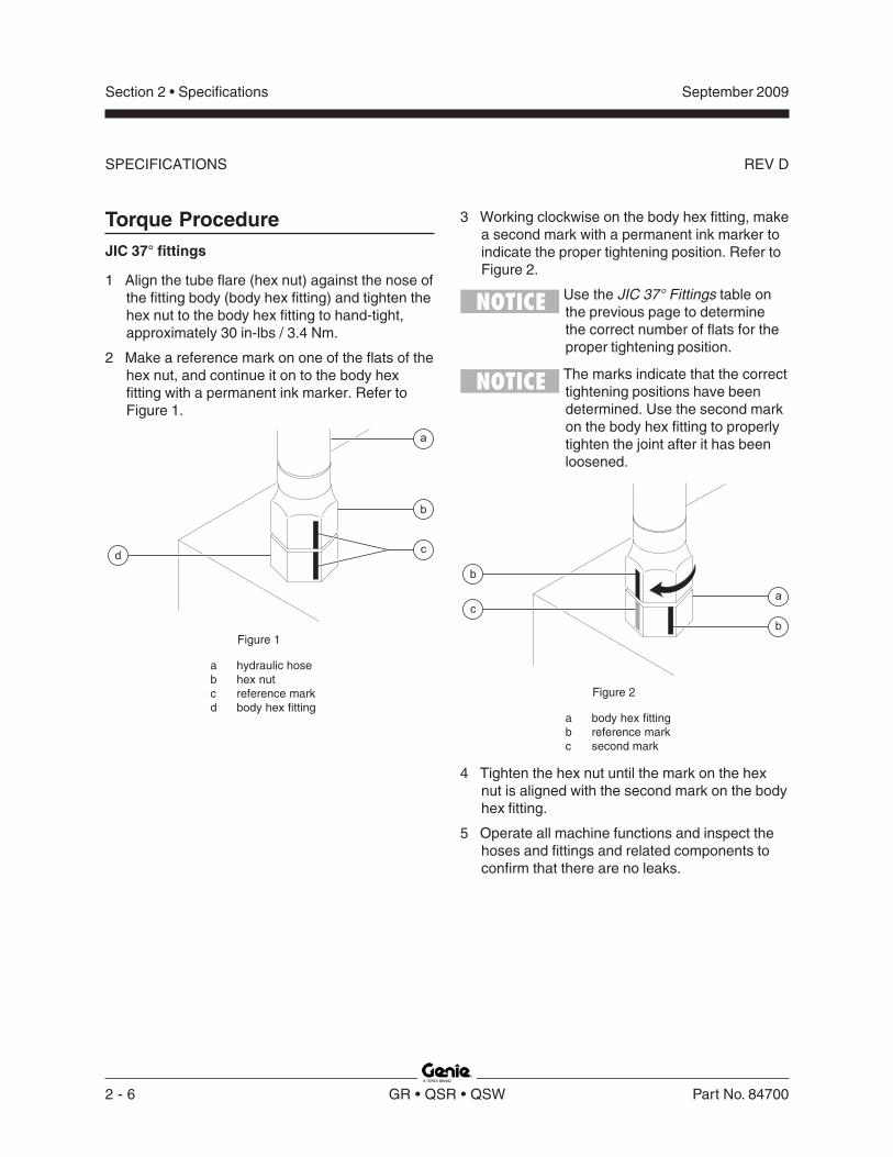
3 Working clockwise on the body hex fitting, makea second mark with a permanent ink marker toindicate the proper tightening position. Refer toFigure 2.
Use the JIC 37° Fittings table onthe previous page to determinethe correct number of flats for theproper tightening position.
The marks indicate that the correcttightening positions have beendetermined. Use the second markon the body hex fitting to properlytighten the joint after it has beenloosened.
Figure 1
a hydraulic hoseb hex nutc reference markd body hex fitting
b
c
a
d
Torque ProcedureJIC 37° fittings
1 Align the tube flare (hex nut) against the nose ofthe fitting body (body hex fitting) and tighten thehex nut to the body hex fitting to hand-tight,approximately 30 in-lbs / 3.4 Nm.
2 Make a reference mark on one of the flats of thehex nut, and continue it on to the body hexfitting with a permanent ink marker. Refer toFigure 1.
Figure 2
a body hex fittingb reference markc second mark
4 Tighten the hex nut until the mark on the hexnut is aligned with the second mark on the bodyhex fitting.
5 Operate all machine functions and inspect thehoses and fittings and related components toconfirm that there are no leaks.
SPECIFICATIONS

Section 2 • Specifications
REV D
September 2009
Part No. 84700 GR • QSR • QSW 2 - 7
SPECIFICATIONS
Size
(mm)in- lbs N m in- lbs N m in-lbs N m in-lbs N m in- lbs N m in- lbs N m in- lbs N m in- lbs N m
5 16 1.8 21 2.4 41 4.63 54 6.18 58 6.63 78 8.84 68 7.75 91 10.36 19 3.05 36 4.07 69 7.87 93 10.5 100 11.3 132 15 116 13.2 155 17.67 45 5.12 60 6.83 116 13.2 155 17.6 167 18.9 223 25.2 1.95 22.1 260 29.4
f t- lbs N m ft- lbs N m ft-lbs N m ft-lbs N m ft- lbs N m ft- lbs N m ft- lbs N m ft- lbs N m
8 5.4 7.41 7.2 9.88 14 19.1 18.8 25.5 20.1 27.3 26.9 36.5 23.6 32 31.4 42.610 10.8 14.7 14.4 19.6 27.9 37.8 37.2 50.5 39.9 54.1 53.2 72.2 46.7 63.3 62.3 84.412 18.9 25.6 25.1 34.1 48.6 66 64.9 88 69.7 94.5 92.2 125 81 110 108 14714 30.1 40.8 40 54.3 77.4 105 103 140 110 150 147 200 129 175 172 23416 46.9 63.6 62.5 84.8 125 170 166 226 173 235 230 313 202 274 269 36518 64.5 87.5 86.2 117 171 233 229 311 238 323 317 430 278 377 371 50320 91 124 121 165 243 330 325 441 337 458 450 610 394 535 525 71322 124 169 166 225 331 450 442 600 458 622 612 830 536 727 715 97024 157 214 210 285 420 570 562 762 583 791 778 1055 682 925 909 1233
LUBED DRY LUBED DRYLUBED DRY LUBED DRY
LUBEDDRYLUBED
Class 12.9Class 4.6
DRYLUBED
METRIC FASTENER TORQUE CHART• This chart is to be used as a guide only unless noted elsewhere in this manual •
LUBED DRY
Class 10.9Class 8.8
DRY
SIZE THREAD
in-lbs N m in- lbs N m in- lbs N m in- lbs N m in- lbs N m20 80 9 100 11.3 110 12.4 140 15.8 130 14.728 90 10.1 120 13.5 120 13.5 160 18 140 15.8
ft - lbs N m ft- lbs N m ft- lbs N m ft- lbs N m ft- lbs N m18 13 17.6 17 23 18 24 25 33.9 21 28.424 14 19 19 25.7 20 27.1 27 36.6 24 32.516 23 31.2 31 42 33 44.7 44 59.6 38 51.524 26 35.2 35 47.4 37 50.1 49 66.4 43 58.314 37 50.1 49 66.4 50 67.8 70 94.7 61 82.720 41 55.5 55 74.5 60 81.3 80 108.4 68 92.113 57 77.3 75 101.6 80 108.4 110 149 93 12620 64 86.7 85 115 90 122 120 162 105 14212 80 108.4 110 149 120 162 150 203 130 17618 90 122 120 162 130 176 170 230 140 18911 110 149 150 203 160 217 210 284 180 24418 130 176 170 230 180 244 240 325 200 27110 200 271 270 366 280 379 380 515 320 43316 220 298 300 406 310 420 420 569 350 4749 320 433 430 583 450 610 610 827 510 69114 350 474 470 637 500 678 670 908 560 7598 480 650 640 867 680 922 910 1233 770 104412 530 718 710 962 750 1016 990 1342 840 11397 590 800 790 1071 970 1315 1290 1749 1090 147712 670 908 890 1206 1080 1464 1440 1952 1220 16547 840 1138 1120 1518 1360 1844 1820 2467 1530 207412 930 1260 1240 1681 1510 2047 2010 2725 1700 23046 1460 1979 1950 2643 2370 3213 3160 4284 2670 362012 1640 2223 2190 2969 2670 3620 3560 4826 3000 4067
LUBEDDRYLUBED
SAE FASTENER TORQUE CHART
Grade 5
DRYLUBED
• This chart is to be used as a guide only unless noted elsewhere in this manual •A574 High Strength Black Oxide BoltsGrade 8
LUBED
1/4
LUBED DRY LUBED DRY
1 1/2
9/16
5/8
3/4
7/8
1
1 1/8
1 1/4
5/16
3/8
7/16
1/2
10.9 12.98.84.6

Section 2 • Specifications September 2009
2 - 8 GR • QSR • QSW Part No. 84700
This page intentionally left blank.

Section 3 • Scheduled Maintenance ProceduresSeptember 2008
Part No. 84700 GR • QSR • QSW 3 - 1
Scheduled Maintenance Procedures
Observe and Obey:
Maintenance inspections shall be completedby a person trained and qualified on themaintenance of this machine.
Scheduled maintenance inspections shall becompleted daily, quarterly, semi-annually,annually and every 2 years as specified on theMaintenance Inspection Report.
Failure to properly complete eachinspection when required maycause death, serious injury orsubstantial machine damage.
Immediately tag and remove from service adamaged or malfunctioning machine.
Repair any machine damage or malfunctionbefore operating the machine.
Use only Genie approved replacement parts.
Machines that have been out of service for aperiod longer than 3 months must complete thequarterly inspection.
Unless otherwise specified, perform eachprocedure with the machine in the followingconfiguration:
· Machine parked on a firm, level surface
· Platform in the stowed position
· Key switch in the off position with the keyremoved
· The red Emergency Stop button in the offposition at both ground and platform controls
· Wheels chocked
· All external AC power supply disconnectedfrom the machine
About This Section
This section contains detailed procedures for eachscheduled maintenance inspection.
Each procedure includes a description, safetywarnings and step-by-step instructions.
Symbols Legend
Safety alert symbol—used to alertpersonnel to potential personalinjury hazards. Obey all safetymessages that follow this symbolto avoid possible injury or death.
Indicates an imminently hazardoussituation which, if not avoided, willresult in death or serious injury.
Indicates a potentially hazardoussituation which, if not avoided,could result in death or seriousinjury.
Indicates a potentially hazardoussituation which, if not avoided,may cause minor or moderateinjury.
Indicates a potentially hazardoussituation which, if not avoided,may result in property damage.
Indicates that a specific result is expected afterperforming a series of steps.
Indicates that an incorrect result has occurredafter performing a series of steps.

Section 3 • Scheduled Maintenance Procedures September 2009
3 - 2 GR • QSR • QSW Part No. 84700
SCHEDULED MAINTENANCE PROCEDURES
Maintenance Symbols Legend
Note: The following symbols have been used inthis manual to help communicate the intent of theinstructions. When one or more of the symbolsappears at the beginning of a maintenanceprocedure, it conveys the meaning below.
Indicates that tools will be required toperform this procedure.
Indicates that new parts will be requiredto perform this procedure.
Indicates that a cold motor or pump willbe required to perform this procedure.
Indicates that dealer service will berequired to perform this procedure.
Pre-delivery Preparation Report
The pre-delivery preparation report containschecklists for each type of scheduled inspection.
Make copies of the Pre-delivery Preparation reportto use for each inspection. Store completed formsas required.
Maintenance Schedule
There are five types of maintenance inspectionsthat must be performed according to a schedule—daily, quarterly, semi-annually, annually, andtwo year. The Scheduled Maintenance ProceduresSection and the Maintenance Inspection Reporthave been divided into five subsections—A, B, C,D, and E. Use the following chart to determinewhich group(s) of procedures are required toperform a scheduled inspection.
Inspection Checklist
Daily or every 8 hours A
Quarterly or every 250 hours A + B
Semi-annually or every 500 hours A + B + C
Annually or every 1000 hours A + B + C + D
Two year or every 2000 hours A + B + C + D + E
Maintenance Inspection Report
The maintenance inspection report containschecklists for each type of scheduled inspection.
Make copies of the Maintenance Inspection Reportto use for each inspection. Maintain completedforms for a minimum of 4 years or in compliancewith employer, jobsite and governmentalregulations and requirements.

Section 3 • Scheduled Maintenance ProceduresSeptember 2008
Part No. 84700 GR • QSR • QSW 3 - 3
Genie Industries USA18340 NE 76th StreetPO Box 97030Redmond, WA 98073-9730(425) 881-1800
Copyright © 2002 by Genie Industries. Genie® is a registered trademark of GenieIndustries. Rev A
Genie UKThe Maltings, Wharf Road
Grantham, LincolnshireNG31- 6BH England
(44) 1476-584333
Pre-DeliverPre-DeliverPre-DeliverPre-DeliverPre-Delivery Preparationy Preparationy Preparationy Preparationy Preparation
Pre-Delivery Preparation Y N R
Pre-operation inspectioncompleted
Maintenance items completed
Function tests completed
Model
Serial number
Date
Machine owner
Inspected by (print)
Inspector signature
Inspector title
Inspector company
Instructions
Use the operator’s manual on your machine.
The Pre-delivery Preparation consists of completingthe Pre-operation Inspection, the Maintenance itemsand the Function Tests.
Use this form to record the results. Place a check inthe appropriate box after each part is completed.Follow the instructions in the operator’s manual.
If any inspection receives an N, remove the machinefrom service, repair and re-inspect it. After repair,place a check in the R box.
LegendY = yes, completedN = no, unable to completeR = repaired
Comments
Fundamentals
It is the responsibility of the dealer to perform thePre-delivery Preparation.
The Pre-delivery Preparation is performed prior toeach delivery. The inspection is designed to discover ifanything is apparently wrong with a machine before itis put into service.
A damaged or modified machine must never be used.If damage or any variation from factory deliveredcondition is discovered, the machine must be taggedand removed from service.
Repairs to the machine may only be made by aqualified service technician, according to themanufacturer's specifications.
Scheduled maintenance inspections shall beperformed by qualified service technicians, accordingto the manufacturer's specifications and therequirements listed in the responsibilities manual.

Section 3 • Scheduled Maintenance Procedures September 2009
3 - 4 GR • QSR • QSW Part No. 84700
This page intentionally left blank.

Section 3 • Scheduled Maintenance ProceduresSeptember 2009
Part No. 84700 GR • QSR • QSW 3 - 5
Maintenance Inspection Report
Checklist B - Rev D Y N R
B-1 Batteries
B-2 Electrical wiring
B-3 Tires and wheels
B-4 Lifting chain
B-5 Clean columns
B-6 Sequencing cables
B-7 Emergency stop
B-8 Key switch
B-9 Horn (if equipped)
B-10 Inverter (if equipped)
B-11 Drive brakes
B-12 Drive speed - stowed
B-13 Drive speed - raised
B-14 Drive speed - slow
B-15 Alarm (if equipped)
B-16 Flashing beacons(if equipped)
B-17 Hydraulic oil analysis
B-18 Breather cap
Checklist C - Rev D Y N R
C-1 Grease platformoverload (if equipped)
C-2 Breather cap - modelswith optional oil
C-3 Test platform overload(if equipped)
Checklist D - Rev D Y N R
D-1 Inspect Mast
D-2 Inspect/lubricate chains
D-3 Hydraulic filter
Checklist E - Rev B Y N R
E-1 Hydraulic oil
Comments
Checklist A - Rev D Y N R
A-1 Inspect the manualsand decals
A-2 Pre-operationinspection
A-3 Function tests
A-4 Obstruction sensingsystem (QSR models)
Perform after 40 hours:
A-5 30 day service
Perform every 100 hours:
A-6 Grease steer yokes
Instructions· Make copies of this report to use for
each inspection.
· Select the appropriate checklist(s) forthe type of inspection to beperformed.
Daily or 8 hoursInspection: A
Quarterly or 250 hoursInspection: A+B
Semi-annually or500 hoursInspection: A+B+C
Annually or1000 hoursInspection: A+B+C+D
Two year or2000 hoursInspection: A+B+C+D+E
· Place a check in the appropriate boxafter each inspection procedure iscompleted.
· Use the step-by-step procedures inthis section to learn how to performthese inspections.
· If any inspection receives an “N”, tagand remove the machine from service,repair and re-inspect it. After repair,place a check in the “R” box.
LegendY = yes, acceptableN = no, remove from service
R = repaired
Model
Serial number
Date
Hour meter
Machine owner
Inspected by (print)
Inspector signature
Inspector title
Inspector company

Section 3 • Scheduled Maintenance Procedures
REV D
September 2009
3 - 6 GR • QSR • QSW Part No. 84700
A-1Inspect the Manuals and DecalsMaintaining the operator’s and safety manuals ingood condition is essential to safe machineoperation. Manuals are included with eachmachine and should be stored in the containerprovided in the platform. An illegible or missingmanual will not provide safety and operationalinformation necessary for a safe operatingcondition.
In addition, maintaining all of the safety andinstructional decals in good condition is mandatoryfor safe machine operation. Decals alert operatorsand personnel to the many possible hazardsassociated with using this machine. They alsoprovide users with operation and maintenanceinformation. An illegible decal will fail to alertpersonnel of a procedure or hazard and couldresult in unsafe operating conditions.
1 Check to make sure that the operator's andsafety manuals are present and complete in thestorage container on the platform.
2 Examine the pages of each manual to be surethat they are legible and in good condition.
Result: The operator's manual is appropriate forthe machine and all manuals are legible and ingood condition.
Result: The operator's manual is notappropriate for the machine or all manuals arenot in good condition or is illegible. Remove themachine from service until the manual isreplaced.
Checklist A Procedures
3 Open the operator's manual to the decalsinspection section. Carefully and thoroughlyinspect all decals on the machine for legibilityand damage.
Result: The machine is equipped with allrequired decals, and all decals are legible andin good condition.
Result: The machine is not equipped with allrequired decals, or one or more decals areillegible or in poor condition. Remove themachine from service until the decals arereplaced.
4 Always return the manuals to the storagecontainer after use.
Note: Contact your authorized Genie distributor orGenie Industries if replacement manuals or decalsare needed.

Section 3 • Scheduled Maintenance Procedures
REV D
September 2009
Part No. 84700 GR • QSR • QSW 3 - 7
CHECKLIST A PROCEDURES
A-2Perform Pre-operation InspectionCompleting a Pre-operation Inspection is essentialto safe machine operation. The Pre-operationInspection is a visual inspection performed by theoperator prior to each work shift. The inspection isdesigned to discover if anything is apparentlywrong with a machine before the operator performsthe function tests. The Pre-operation Inspectionalso serves to determine if routine maintenanceprocedures are required.
Complete information to perform this procedure isavailable in the appropriate operator's manual.Refer to the Operator's Manual on your machine.
A-3Perform Function TestsCompleting the function tests is essential to safemachine operation. Function tests are designed todiscover any malfunctions before the machine isput into service. A malfunctioning machine mustnever be used. If malfunctions are discovered, themachine must be tagged and removed fromservice.
Complete information to perform this procedure isavailable in the appropriate operator's manual.Refer to the Operator's Manual on your machine.

Section 3 • Scheduled Maintenance Procedures
REV D
September 2009
3 - 8 GR • QSR • QSW Part No. 84700
A-4Test the Obstruction SensingSystem (QSR models only)
Genie specifications require that this procedure beperformed every 8 hours or daily, whichevercomes first.
1 Raise the platform approximately 4 feet / 1.2 m.
2 Place a 15 lb / 6.8 kg weight onto one of theobstruction sensing pads, of an area equal to3 inches / 7.3 cm in diameter.
Note: The weight must be placed approximately2 inches / 5.08 cm from the edge of the obstructionsensing pad.
3 At the ground controls, attempt to lower theplatform.
Result: The obstruction sensing alarm soundsand the platform will not lower. The system isworking properly.
Result: The obstruction sensing alarm doesnot sound and the platform will lower. Thesystem is not functioning correctly. Replace thepad. Refer to Repair procedure 12-1, How toReplace an Obstruction Sensing Pad.
4 Remove the the weight from the pad. Push inthe red Emergency Stop button to the offposition at the ground controls, then pull out thered Emergency Stop button to the on position atthe ground controls.
5 Repeat the procedure, beginning with step 2, foreach of the remaining obstruction sensingpads.
a obstruction sensing pad(battery tray)
b obstruction sensing pad(ground controls side)
c obstruction sensing pad(steer end)
d obstruction sensing pad(hydraulic tank side)
Place the15 lb / 6.8 kg weight2 inches / 5.08 cm from theedge of the obstruction pad.
Steer End
Non-steer End
Hydraulic TankSide
Ground ControlsSide
a
c
bd

Section 3 • Scheduled Maintenance Procedures
REV D
September 2009
Part No. 84700 GR • QSR • QSW 3 - 9
A-5Perform 30 Day Service
The 30 day maintenance procedure is a one timeprocedure to be performed after the first 30 days or40 hours of usage. After this interval, refer to themaintenance tables for continued scheduledmaintenance.
1 Perform the following maintenance procedures:
· B-3 Inspect the Tires and Wheels(including castle nut torque)
· D-4 Replace the Hydraulic TankReturn Filter
A-6Grease the Steer Yokes
Genie specifications require that this procedure beperformed every 100 hours of operation.
Regular application of lubrication to the steer yokesis essential to good machine performance andservice life. Continued use of an insufficientlygreased steer yoke will result in componentdamage.
1 Locate the grease fitting on the top of the steeryoke.
2 Pump multipurpose grease into the steer yokeuntil the steer yoke is full and grease is beingforced past the bearings. Repeat this step forthe other steer yoke.
Grease Specification
Chevron Ultra-duty grease, EP NLGI 1 (lithium based)or equivalent

Section 3 • Scheduled Maintenance Procedures
REV D
September 2009
3 - 10 GR • QSR • QSW Part No. 84700
Checklist B Procedures
B-1Inspect the Batteries
Genie specifications require that this procedure beperformed every 250 hours or quarterly, whichevercomes first.
Proper battery condition is essential to goodmachine performance and operational safety.Improper fluid levels or damaged cables andconnections can result in component damage andhazardous conditions.
Electrocution/burn hazard. Contactwith hot or live circuits could resultin death or serious injury. Removeall rings, watches and otherjewelry.
Bodily injury hazard. Batteriescontain acid. Avoid spilling orcontacting battery acid. Neutralizebattery acid spills with baking sodaand water.
1 Put on protective clothing and eye wear.
2 GR-12: Raise the platformapproximately 3 feet / 1 m.GR-15 and GR-20: Raise the platformapproximately 5 feet / 1.5 m.
3 Open the battery cover. Rest the cover againstthe chassis.
4 Lower the platform until the mast just contactsthe battery cover.
Crushing hazard. Keep handsclear of the battery cover whenlowering the platform.
5 Be sure that the battery cable connections arefree of corrosion.
Note: Adding terminal protectors and a corrosionpreventative sealant will help eliminate corrosionon the battery terminals and cables.
-
+
-
+
-
+
-
+
275A FuseF6
-
+
QD1
a
b
c
Battery Charger
U9
RDBK
d
a batteries B5b 275A fuse F6c quick disconnect QD1d battery charger U9
6 Be sure that the battery hold downs and cableconnections are tight.
7 Be sure that the battery separator wireconnections are tight (if equipped).
8 Fully charge the batteries. Allow the batteries torest 24 hours before performing this procedureto allow the battery cells to equalize.
9 Put on protective clothing and eye wear.
Models without maintenance-free or sealedbatteries:
10 Remove the battery vent caps and check thespecific gravity of each battery cell with ahydrometer. Note the results.

Section 3 • Scheduled Maintenance Procedures
REV D
September 2009
Part No. 84700 GR • QSR • QSW 3 - 11
CHECKLIST B PROCEDURES
11 Check the ambient air temperature and adjustthe specific gravity reading for each cell asfollows:
• Add 0.004 to the reading of each cell forevery 10° / 5.5° C above 80° F / 26.7° C.
• Subtract 0.004 from the reading of each cell forevery 10° / 5.5° C below 80° F / 26.7° C.
Result: All battery cells display an adjustedspecific gravity of 1.277 or higher. The batteryis fully charged. Proceed to step 15.
Result: One or more battery cells display aspecific gravity of 1.217 or below. Proceed tostep 12.
12 Perform an equalizing charge OR fully chargethe batteries and allow the batteries to rest atleast 6 hours.
13 Remove the battery vent caps and check thespecific gravity of each battery cell with ahydrometer. Note the results.
14 Check the ambient air temperature and adjustthe specific gravity reading for each cell asfollows:
• Add 0.004 to the reading of each cell forevery 10° / 5.5° C above 80° F / 26.7° C.
• Subtract 0.004 from the reading of each cell forevery 10° / 5.5° C below 80° F / 26.7° C.
Result: All battery cells display a specific gravityof 1.277 or greater. The battery is fully charged.Proceed to step 15.
Result: The difference in specific gravityreadings between cells is greater than 0.1 ORthe specific gravity of one or more cells is lessthan 1.177. Replace the battery.
15 Check the battery acid level. If needed,replenish with distilled water to 1/8 inch / 3 mmbelow the bottom of the battery fill tube. Do notoverfill.
16 Install the vent caps and neutralize anyelectrolyte that may have spilled.
All models:
17 Check each battery pack and verify that thebatteries are wired correctly.
18 Inspect the battery charger plug and pigtail fordamage or excessive insulation wear. Replaceas required.
19 Connect the battery charger to a properlygrounded 115V/60Hz or 230V/60Hz singlephase AC power supply.
Result: The charger should operate and begincharging the batteries.
If, simultaneously, the charger alarm soundsand the LEDs blink one time, correct thecharger connections at the fuse and battery.The charger will then operate correctly andbegin charging the batteries.
If, simultaneously, the charger alarm soundsand the LEDs blink two times, the input voltageis too low or too high. Correct the voltage issue.The charger will then operate correctly andbegin charging the batteries.
If, simultaneously, the charger alarm soundsand the LEDs blink three times, the charger isoverheated. Allow the charger to cool. Thecharger will then operate correctly and begincharging the batteries.
Note: For best results, use an extension ofadequate size with a length no longer than 50 feet /15 m.
Note: If you have any further questions regardingthe battery charger operation, please contact theGenie Industries Scissor Service Department.

Section 3 • Scheduled Maintenance Procedures
REV D
September 2009
3 - 12 GR • QSR • QSW Part No. 84700
CHECKLIST B PROCEDURES
B-2Inspect the Electrical Wiring
Genie specifications require that this procedure beperformed every 250 hours or quarterly, whichevercomes first.
Maintaining electrical wiring in good condition isessential to safe operation and good machineperformance. Failure to find and replace burnt,chafed, corroded or pinched wires could result inunsafe operating conditions and may causecomponent damage.
Electrocution/burn hazard. Contactwith hot or live circuits could resultin death or serious injury. Removeall rings, watches and otherjewelry.
1 Inspect the underside of the chassis fordamaged or missing ground straps.
2 Inspect the following areas for burnt, chafed,corroded and loose wires:
· Mast cable
· Platform controls
· Power to platform wiring
3 Inspect the following areas for burnt, chafed,corroded and loose wires:
· Ground control panel
· Hydraulic power unit
4 Inspect for a liberal coating of dielectric greasein all wiring connections between the ECM andthe platform controls, and level sensor wiring.
5 Turn the key switch to ground control and pullout the red Emergency Stop button to the onposition at both the ground and platformcontrols.
6 Raise the platform approximately 8 feet / 2.4 mfrom the ground.
7 Place a lifting strap from an overhead craneunder the platform. Support the platform. Do notapply any lifting pressure.
Component damage hazard. Theplatform railings can be damagedif they are used to lift the platform.Do not attach the lifting strap tothe platform railings.
8 Inspect the center chassis area for burnt,chafed and pinched cables.
9 Open the battery tray cover.
10 Inspect the battery tray for burnt, chafed andpinched cables.
11 Close the battery tray cover.
12 Remove the strap from the platform.
13 Lower the platform to the stowed position andturn the machine off.

Section 3 • Scheduled Maintenance Procedures
REV D
September 2009
Part No. 84700 GR • QSR • QSW 3 - 13
CHECKLIST B PROCEDURES
B-3Inspect the Tires and Wheels(including castle nut torque)
Genie specifications require that this procedure beperformed every 250 hours or quarterly, whichevercomes first.
Maintaining the tires and wheels in goodcondition is essential to safe operation and goodperformance. Tire and/or wheel failure could resultin a machine tip-over. Component damage mayalso result if problems are not discovered andrepaired in a timely fashion.
1 Check the tire surface and sidewalls for cuts,cracks, punctures and unusual wear.
2 Check each wheel for damage, bends andcracks.
3 Remove the cotter pin and check each castlenut for proper torque. Refer to Section 2,Specifications.
Note: Always replace the cotter pin with a new onewhen removing the castle nut or when checkingthe torque of the castle nut.
4 Install a new cotter pin. Bend the cotter pin tolock it in place.
B-4Check the Lifting ChainAdjustments
Genie specifications require that this procedure beperformed every 250 hours or quarterly, whichevercomes first.
Maintaining proper adjustment of the lifting chainsis essential to safe machine operation. Failure tomaintain proper chain adjustment could result in anunsafe operating condition and may causecomponent damage.
1 Fully lower the platform and measure themaximum height of the machine.
Result: The machine is within specification.Refer to Section 2, Specifications.
Result: The machine is not within specification.Adjust the chains. Refer to Repair procedure3-3, How to Adjust the Lifting Chains.

Section 3 • Scheduled Maintenance Procedures
REV D
September 2009
3 - 14 GR • QSR • QSW Part No. 84700
a
c
b
d
CHECKLIST B PROCEDURES
B-5Clean and Lubricate the Columns
Genie specifications require that this procedure beperformed every 250 hours or quarterly, whichevercomes first.
Clean and properly lubricated columns areessential to good machine performance and safeoperation. Extremely dirty conditions may requirethat the columns be cleaned and lubricated moreoften.
1 Raise the platform to the maximum height.
2 Place a lifting strap from an overhead craneunder the platform. Support the platform. Do notapply any lifting pressure.
Component damage hazard. Theplatform railings can be damagedif they are used to lift the platform.Do not attach the lifting strap tothe platform railings.
3 Visually inspect the inner and outer channels ofthe columns for debris or foreign material. Ifnecessary, use a mild cleaning solvent to cleanthe columns.
Bodily injury hazard. Thisprocedure will require the use ofadditional access equipment. Donot place ladders or scaffold on oragainst any part of the machine.Performing this procedure withoutthe proper skills and tools couldresult in death or serious injury.Dealer service is stronglyrecommended.
4 If needed, apply a generous amount ofBoe-lube wax to the inside and outsidechannels of each column.
B-6Adjust the Sequencing Cables
Genie specifications require that this procedure beperformed every 250 hours or quarterly, whichevercomes first.
Maintaining proper adjustment of the sequencingcables is essential for safe machine operation. Anunsafe working condition exists if the sequencingcables are improperly adjusted. A frequent checkallows the inspector to identify changes in thesequencing cables operating condition that mightindicate damage.
1 Fully lower the platform.
2 Locate the compression spring on eachsequencing cable.
Note: The spring is located between the nylock nutand the upper sequencing bracket.
a nylock nutb springc upper sequencing bracketd sequencing cable

Section 3 • Scheduled Maintenance Procedures
REV D
September 2009
Part No. 84700 GR • QSR • QSW 3 - 15
CHECKLIST B PROCEDURES
3 Confirm proper tension of each sequencingcable by measuring the height of the springbetween the nylock nut and the uppersequencing bracket.
Result: The measurement is withinspecification. Proceed to step 7.
Result: The measurement is not withinspecification. Proceed to step 4.
Sequencing cable spring specification
Measurement, compressed 15/16 inch2.4 cm
4 Adjust the spring compressed length by turningthe nylock nut clockwise to decrease the springlength or counterclockwise to increase thespring length.
Component damage hazard. Donot compress the spring to lessthan specification.
5 Raise and lower the platform through threecomplete cycles.
6 Repeat this procedure beginning with step 3.
7 Repeat steps 3 through 5 for each sequencingcable as required.
B-7Test the Emergency StopGenie specifications require that this procedure beperformed every 250 hours or quarterly, whichevercomes first.
A properly functioning Emergency Stop is essentialfor safe machine operation. An improperlyoperating red Emergency Stop button will fail toshut off power and stop all machine functions,resulting in a hazardous situation.
Note: As a safety feature, selectingand operating the ground controls will override theplatform controls, except the platform redEmergency Stop button.
1 Turn the key switch to ground control and pullout the red Emergency Stop button to the onposition at both the ground and platformcontrols.
2 Push in the red Emergency Stop button at theground controls to the off position.
Result: No machine functions should operate.
3 Turn the key switch to platform control and pullout the red Emergency Stop button to the onposition at both the ground and platformcontrols.
4 Push down the red Emergency Stop button atthe platform controls to the off position.
Result: No machine functions should operate.
Note: The red Emergency Stop button at theground controls will stop all machine operation,even if the key switch is switched to platformcontrol.

Section 3 • Scheduled Maintenance Procedures
REV D
September 2009
3 - 16 GR • QSR • QSW Part No. 84700
CHECKLIST B PROCEDURES
B-8Test the Key SwitchGenie specifications require that this procedure beperformed every 250 hours or quarterly, whichevercomes first.
Proper key switch action and response is essentialto safe machine operation. The machine can beoperated from the ground or platform controls andthe activation of one or the other is accomplishedwith the key switch. Failure of the key switch toactivate the appropriate control panel could causea hazardous operating situation.
Note: Perform this procedure from the groundusing the platform controls. Do not stand in theplatform.
1 Pull out the red Emergency Stop button to theon position at both the ground and platformcontrols.
2 Turn the key switch to platform control.
3 Check the platform up/down function from theground controls.
Result: The machine functions should notoperate.
4 Turn the key switch to ground control.
5 Check the machine functions from the platformcontrols.
Result: The machine functions should notoperate.
6 Turn the key switch to the off position.
7 Test the machine functions from the ground andplatform controls.
Result: No machine functions should operate.
B-9Test the Automotive-style Horn(if equipped)Genie specifications require that this procedure beperformed every 250 hours or quarterly, whichevercomes first.
The horn is activated at the platform controls andsounds at the ground as a warning to groundpersonnel. An improperly functioning horn willprevent the operator from alerting groundpersonnel of hazards or unsafe conditions.
1 Turn the key switch to platform control andpull out the red Emergency Stop button to theon position at both the ground andplatform controls.
2 Push down the horn button at the platformcontrols.
Result: The horn should sound.

Section 3 • Scheduled Maintenance Procedures
REV D
September 2009
Part No. 84700 GR • QSR • QSW 3 - 17
CHECKLIST B PROCEDURES
FAULTFAULT
PART NUMBER XXX
PART NUMBER XXX
OUTPUTOUTPUT
POWER INVERTER
POWER INVERTER25V
24V-22V24V-22V21V
b
c
d
a
B-10Inspect the Voltage Inverter(if equipped)Genie specifications require that this procedure beperformed every 250 hours or quarterly, whichevercomes first.
The inverter is activated whenever the power is on,and an electrical tool is connected to the inverterand turned on.
1 Inspect the inverter plug and pigtail for damageor excessive insulation wear. Replace asrequired.
2 Turn the key switch to the on position and pullout the red Emergency Stop button to the onposition at both the ground and platformcontrols.
a right fault LEDb left fault LEDc 25V LEDd 21V LED
3 Connect an appropriate power tool to theinverter. Activate the tool.
Result: The power tool should operate. Theremay be a brief (0.5 second) delay if the powertool has not been used in the previous 10minutes.
If the left fault LED (REV_POL) is illuminated,the inverter is connected to batteries with theincorrect polarity. Correct the polarity issue withthe red wire to battery positive and the blackwire to battery negative. The inverter will thenoperate correctly and begin supplying ACpower.
If the right fault LED (123) blinks one time, thepower draw is too high. The tool being usedrequires too much power to operate or is beingused at or near the limit of the inverter for anextended period of time. Reduce the powerdraw. The inverter will then operate correctlyand begin supplying AC power.
If the right fault LED (123) blinks two times, theGround Fault Interrupt (GFI) has beenactivated. A short circuit or partial short existsbetween the AC hot and ground in the tool oroutlet. Check the tool for burnt, chafed,corroded and loose wires, and inspect the toolfor internal moisture. Correct the short circuit ormoisture issue OR inspect the wiring in thepower-to-platform box. The inverter will thenoperate correctly and begin supplying ACpower.
If right fault LED (123) blinks three times, theinverter is overheated. Allow the inverter tocool. The inverter will then operate correctlyand begin supplying AC power.
If the battery 25 volt fault LED (25V) blinks onetime, the battery voltage is over 30V. Operatethe machine to lower the voltage level. Theinverter will then operate correctly and beginsupplying AC power.
If the battery 21 volt fault LED (21V) blinks onetime, the battery voltage is less than 20V DC.The inverter will continue to operate until thebattery voltage falls to 17.8V DC.

Section 3 • Scheduled Maintenance Procedures
REV D
September 2009
3 - 18 GR • QSR • QSW Part No. 84700
CHECKLIST B PROCEDURES
a
B-11Test the Drive Brakes
Genie specifications require that this procedure beperformed every 250 hours or quarterly, whichevercomes first.
Proper brake action is essential to safe machineoperation. The drive brake function should operatesmoothly, free of hesitation, jerking and unusualnoise. Hydraulically-released individual wheelbrakes can appear to operate normally when notfully operational.
Note: Perform this procedure with the machine ona firm, level surface that is free of obstructions.
Note: Be sure the platform extension deck is fullyretracted and the platform is in the stowed position.
1 Mark a test line on the ground for reference.
2 Turn the key switch to platform control and pullout the red Emergency Stop button to the onposition at both the ground and platformcontrols.
3 Lower the platform to the stowed position.
4 Press the drive function select button.
5 Choose a point on the machine; i.e., contactpatch of a tire, as a visual reference for usewhen crossing the test line.
a drive function select button BN8
6 Bring the machine to top drive speed beforereaching the test line. Release the functionenable switch or the joystick when yourreference point on the machine crosses the testline.
7 Measure the distance between the test line andyour machine reference point. Refer to Section2, Specifications.
Note: The brakes must be able to hold the machineon any slope it is able to climb.

Section 3 • Scheduled Maintenance Procedures
REV D
September 2009
Part No. 84700 GR • QSR • QSW 3 - 19
CHECKLIST B PROCEDURES
a
B-12Test the Drive Speed -Stowed Position
Genie specifications require that this procedure beperformed every 250 hours or quarterly, whichevercomes first.
Proper drive functions are essential to safemachine operation. The drive function shouldrespond quickly and smoothly to operator control.Drive performance should also be free ofhesitation, jerking and unusual noise over theentire proportionally controlled speed range.
Note: Perform this procedure with the machine ona firm, level surface that is free of obstructions.
1 Create start and finish lines by marking twolines on the ground 40 feet / 12.2 m apart.
2 Turn the key switch to platform control and pullout the red Emergency Stop button to the onposition at both the ground and platformcontrols.
3 Lower the platform to the stowed position.
4 Press the drive function select button.
5 Choose a point on the machine; i.e., contactpatch of a tire, as a visual reference for usewhen crossing the start and finish lines.
a drive function select button BN8
6 Bring the machine to top drive speed beforereaching the start line. Begin timing when yourreference point on the machine crosses thestart line.
7 Continue at full speed and note the time whenyour reference point on the machine passesover the finish line. Refer to Section 2,Specifications.
Section 3 • Scheduled Maintenance Procedures
REV D
September 2009
3 - 20 GR • QSR • QSW Part No. 84700
CHECKLIST B PROCEDURES
ba
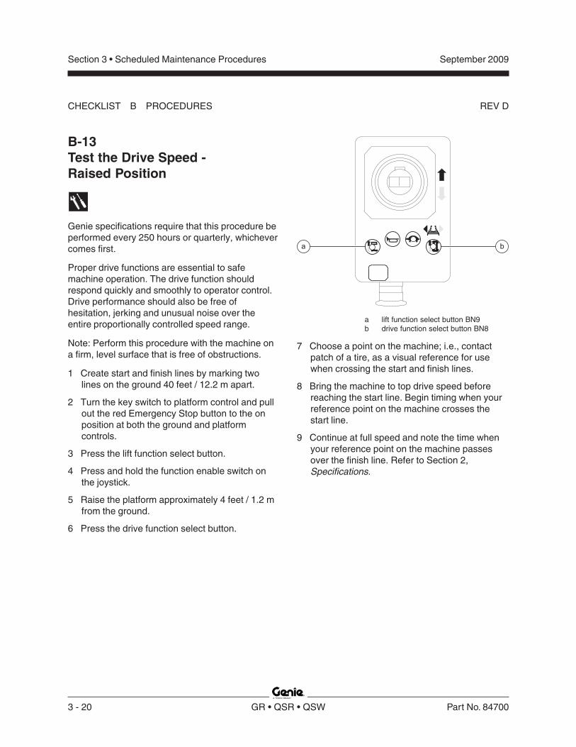
B-13Test the Drive Speed -Raised Position
Genie specifications require that this procedure beperformed every 250 hours or quarterly, whichevercomes first.
Proper drive functions are essential to safemachine operation. The drive function shouldrespond quickly and smoothly to operator control.Drive performance should also be free ofhesitation, jerking and unusual noise over theentire proportionally controlled speed range.
Note: Perform this procedure with the machine ona firm, level surface that is free of obstructions.
1 Create start and finish lines by marking twolines on the ground 40 feet / 12.2 m apart.
2 Turn the key switch to platform control and pullout the red Emergency Stop button to the onposition at both the ground and platformcontrols.
3 Press the lift function select button.
4 Press and hold the function enable switch onthe joystick.
5 Raise the platform approximately 4 feet / 1.2 mfrom the ground.
6 Press the drive function select button.
a lift function select button BN9b drive function select button BN8
7 Choose a point on the machine; i.e., contactpatch of a tire, as a visual reference for usewhen crossing the start and finish lines.
8 Bring the machine to top drive speed beforereaching the start line. Begin timing when yourreference point on the machine crosses thestart line.
9 Continue at full speed and note the time whenyour reference point on the machine passesover the finish line. Refer to Section 2,Specifications.

Section 3 • Scheduled Maintenance Procedures
REV D
September 2009
Part No. 84700 GR • QSR • QSW 3 - 21
a
CHECKLIST B PROCEDURES
B-14Test the Slow Drive Speed
Genie specifications require that this procedure beperformed every 250 hours or quarterly, whichevercomes first.
Proper drive functions are essential to safemachine operation. The drive function shouldrespond quickly and smoothly to operator control.Drive performance should also be free ofhesitation, jerking and unusual noise over theentire proportionally controlled speed range.
Note: Perform this procedure with the machine ona firm, level surface that is free of obstructions.
1 Create start and finish lines by marking twolines on the ground 40 feet / 12.2 m apart.
2 Turn the key switch to platform control and pullout the red Emergency Stop button to the onposition at both the ground and platformcontrols.
3 Lower the platform to the stowed position.
4 Press the slow speed select button.
5 Choose a point on the machine; i.e., contactpatch of a tire, as a visual reference for usewhen crossing the start and finish lines.
a slow speed select button BN6
6 Bring the machine to top drive speed beforereaching the start line. Begin timing when yourreference point on the machine crosses thestart line.
7 Continue at full speed and note the time whenyour reference point on the machine passesover the finish line. Refer to Section 2,Specifications.

Section 3 • Scheduled Maintenance Procedures
REV D
September 2009
3 - 22 GR • QSR • QSW Part No. 84700
CHECKLIST B PROCEDURES
B-15Test the Motion Alarm(if equipped)Genie specifications require that this procedure beperformed every 250 hours or quarterly, whichevercomes first.
Alarms are used to alert operators and groundpersonnel of machine proximity and motion. Themotion alarm is located in the ground control boxand, when activated, will sound at 60 beeps perminute.
1 Turn the key switch to ground control and pullout the red Emergency Stop button to the onposition at both the ground and platformcontrols.
2 Raise the platform approximately 1 foot / 0.3 m.
Result: When raising the platform, the motionalarm should sound.
3 Lower the platform to the stowed position.
Result: When lowering the platform, the motionalarm should sound.
4 Turn the key switch to platform controls.
5 Press the lift function select button.
6 Press and hold the function enable switch onthe joystick. Move the joystick off center, holdfor a moment and then release it. Move thejoystick off center in the opposite direction, holdfor a moment and then release it.
Result: The motion alarm should sound whenthe joystick is moved off center in eitherdirection.
7 Press the drive function select switch.
8 Press and hold the function enable switch onthe joystick. Move the joystick off center, holdfor a moment and then release it. Move thejoystick off center in the opposite direction, holdfor a moment and then release it.
Result: The motion alarm should sound whenthe joystick is moved off center in eitherdirection.
9 Press and hold the function enable switch onthe joystick. Press and hold the thumb rockerswitch for a moment to the left position and thenrelease it. Press and hold the thumb rockerswitch for a moment to the right position andthen release it.
Result: The motion alarm should sound whenthe rocker switch is moved off center in eitherdirection.

Section 3 • Scheduled Maintenance Procedures
REV D
September 2009
Part No. 84700 GR • QSR • QSW 3 - 23
CHECKLIST B PROCEDURES
B-16Test the Flashing Beacons(if equipped)Genie specifications require that this procedure beperformed every 250 hours or quarterly, whichevercomes first.
Flashing beacons are used to alert operators andground personnel of machine proximity andmotion. The flashing beacons are located on bothsides of the mast.
1 Turn the key switch to ground control and pullout the red Emergency Stop button to the onposition at both the ground and platformcontrols.
Result: The beacons should flash.
2 Turn the key switch to platform controls.
Result: The beacons should flash.
B-17Perform Hydraulic Oil Analysis
Genie specifications require that this procedure beperformed every 250 hours or quarterly, whichevercomes first.
Replacement or testing of the hydraulic oil isessential for good machine performance andservice life. Dirty oil may cause the machine toperform poorly and continued use may causecomponent damage. Extremely dirty conditionsmay require oil changes to be performed moreoften.
Before replacing the hydraulic oil, the oil may betested by an oil distributor for specific levels ofcontamination to verify that changing the oil isnecessary.If the hydraulic oil is not replaced at the twoyear inspection, test the oil quarterly. Replacethe oil when it fails the test. See E-1, Test orReplace the Hydraulic Oil.
Section 3 • Scheduled Maintenance Procedures
REV D
September 2009
3 - 24 GR • QSR • QSW Part No. 84700
CHECKLIST B PROCEDURES
B-18Inspect the Breather CapGenie specifications require that this procedure beperformed every 250 hours or quarterly, whichevercomes first.
A free-breathing hydraulic tank cap is essential forgood machine performance and service life. A dirtyor clogged cap may cause the machine to performpoorly. Extremely dirty conditions may require thatthe cap be inspected more often.
1 Remove the breather cap from the hydraulictank.
2 Check for proper venting.
Result: Air passes through the breather cap.
Result: If air does not pass through the cap,clean or replace the cap. Proceed to step 3.
Note: When checking for positive tank cap venting,air should pass freely through the cap.
3 Using a mild solvent, carefully wash the capventing system. Dry using low pressurecompressed air. Repeat step 2.
4 Install the breather cap onto the hydraulic tank.

Section 3 • Scheduled Maintenance Procedures
REV D
September 2009
Part No. 84700 GR • QSR • QSW 3 - 25
C-1Grease the Platform OverloadMechanism (if equipped)
Genie specifications require that this procedure beperformed every 500 hours or 6 months, whichevercomes first. Perform this procedure more often ifdusty conditions exist.
Application of lubrication to the platform overloadmechanism is essential to safe machine operation.Continued use of an improperly greased platformoverload mechanism could result in the system notsensing an overloaded platform condition and willresult in component damage.
1 Locate the grease fittings on each pivot pin ofthe platform overload assembly.
2 Thoroughly pump grease into each greasefitting using a multi-purpose grease.
Checklist C Procedures
C-2Replace theHydraulic Tank Breather Cap -Models with Optional Hydraulic Oil
Genie specifications require that this procedure beperformed every 500 hours or six months,whichever comes first OR when the machine failsto lift the maximum rated load.
The hydraulic tank is a vented-type tank. Thebreather cap has an internal air filter that canbecome clogged or, over time, can deteriorate. Ifthe breather cap is faulty or improperly installed,impurities can enter the hydraulic system whichmay cause component damage. Extremely dirtyconditions may require that the cap be inspectedmore often.
1 Remove and discard the hydraulic tank breathercap.
2 Install and new cap onto the tank.

Section 3 • Scheduled Maintenance Procedures
REV D
September 2009
3 - 26 GR • QSR • QSW Part No. 84700
C-3Test the Platform OverloadSystem (if equipped)
Genie specifications require that this procedure beperformed every 500 hours or 6 months, whichevercomes first.
Testing the platform overload system regularly isessential to safe machine operation. Continueduse of an improperly operating platform overloadsystem could result in the system not sensing anoverloaded platform condition. Machine stabilitycould be compromised resulting in the machinetipping over.
Note: Perform this procedure with the machine ona firm, level surface.
1 Turn the key switch to platform control and pullout the red Emergency Stop button to the onposition at both the ground and platformcontrols.
2 Determine the maximum platform capacity.Refer to the machine serial plate.
3 Using a suitable lifting device, place anappropriate test weight equal to the maximumplatform capacity in the center of the platformfloor.
Result: The diagnostic display at the groundcontrols will show two flat bars and a blinkinglight, indicating a normal condition, and thediagnostic display at the platform controls willshow the battery condition. Refer to Repairprocedure 1-3, How to Determine the BatteryVoltage.
Result: The diagnostic display will show 'OL' atboth the ground and platform controls. Theplatform overload system is not operatingproperly. Refer to Repair Procedure 11-1,Calibrate the Platform Overload System (ifequipped).
4 Add an additional weight to the platform not toexceed 20% of the maximum rated load. Referto the machine serial plate.
Result: The diagnostic display will show 'OL' atboth the ground and platform controls. Theplatform overload system is operating properly.
Result: The diagnostic display at the groundcontrols will show two flat bars and a blinkinglight and the diagnostic display at the platformcontrols will show the battery condition. Theplatform overload system is not operatingproperly. Refer to Repair Procedure 11-1,Calibrate the Platform Overload System (ifequipped).
5 Test all machine functions from the platformcontrols.
Result: All platform control functions should notoperate.
CHECKLIST C PROCEDURES

Section 3 • Scheduled Maintenance Procedures
REV D
September 2009
Part No. 84700 GR • QSR • QSW 3 - 27
CHECKLIST C PROCEDURES
6 Turn the key switch to ground control.
7 Test all machine functions from the groundcontrols.
Result: All ground control functions should notoperate.
8 Lift the test weight off the platform floor using asuitable lifting device. Turn the key switch to theoff position.
9 Turn the key switch to ground control.
Result: The diagnostic display at the groundcontrols will show two flat bars and a blinkinglight, indicating a normal condition, and thediagnostic display at the platform controls willshow the battery condition.
Result: The diagnostic display will show 'OL' atboth the ground and platform controls. Theplatform overload system is not operatingproperly. Refer to Repair Procedure 11-1,Calibrate the Platform Overload System (ifequipped).
10 Test all machine functions from the groundcontrols.
Result: All ground control functions shouldoperate normally.
11 Turn the key switch to platform control.
12 Test all machine functions from the platformcontrols.
Result: All platform control functions shouldoperate.
Note: If the platform overload system is notoperating properly, refer to Repair Procedure 11-1,Calibrate the Platform Overload System (ifequipped).

Section 3 • Scheduled Maintenance Procedures
REV D
September 2009
3 - 28 GR • QSR • QSW Part No. 84700
a
b
c
Checklist D Procedures
D-1Inspect the Mast Assemblyfor Wear
Genie specifications require that this procedurebe performed every 1000 hours or annually,whichever comes first.
Detection of excessive or unusual wear in the mastassembly is essential for safe machine operation.An unsafe working condition exists if the mastassembly has excessive wear and/or does notoperate smoothly, free of hesitation and binding.
1 Remove the mast covers.
2 Raise the platform until approximately4 inches / 10 cm of each column is visible.
3 GR-12 and GR-15: Visually inspect the top ofeach column for clearance between the rollerwheels and the adjacent column surface.GR-20: Visually inspect the top of each columnfor clearance between the slider block and theadjacent column surface.
Result: There should be an equal amount ofdistance between the roller wheel/slider blockand the column on each side.
Note: If mast inspection results in a measurementthat is not within specification, refer to Repairprocedure 3-2, How to Adjust the Glide Pads.
4 Loosen but do not remove the adjustment nuton the sequencing cable located at the top ofthe first column.
5 Raise the platform approximately 3 feet / 1 mabove the top of the drive chassis.
6 Place a jack stand on the top of the batterycover, centered under the platform. Adjust thejack stand height to 24 inches / 60 cm.
7 Lower the platform onto the jack stand justenough to take the weight off the lifting chains.
Crushing hazard. Keep handsclear of the jack stand whenlowering the platform.
GR-15 shown
a mast coverb idler wheelc spacer

Section 3 • Scheduled Maintenance Procedures
REV D
September 2009
Part No. 84700 GR • QSR • QSW 3 - 29
CHECKLIST D PROCEDURES
8 Inspect each idler wheel for the following:
· Excessive wear on the side flanges
· Unusual wear
· Movement side to side in excess of0.040 inch / 1 mm
· Any wheel movement front to back
Note: If idler wheel inspection results in a conditionthat is not within specification, refer to Repairprocedure 3-1, How to Assemble the Mast.
9 GR-20: Inspect each wear pad for the following:
· Excessive or unusual wear
Note: If a wear pad displays excessive or unusualwear, refer to Repair procedure 3-1, How toAssemble the Mast.
10 Raise the platform slightly and remove the jackstand. Lower the platform to the stowedposition.
11 Install the mast covers and adjust thesequencing cable. See B-6, Adjust theSequencing Cables.
D-2Inspect and Lubricate theLifting Chains
Genie specifications require that this procedurebe performed every 1000 hours or annually,whichever comes first.
Lubricated chains are essential to good machineperformance and safe operation. Extremely dirtyconditions may require that the chains be cleanedand lubricated more often.
1 Thoroughly inspect the lifting chains. Refer toRepair Procedure 3-3, How to Inspect theLifting Chains.
2 Raise the platform to the maximum height.
3 Place a lifting strap from an overhead craneunder the platform. Support the platform. Do notapply any lifting pressure.
Component damage hazard. Theplatform railings can be damagedif they are used to lift the platform.Do not attach the lifting strap tothe platform railings.
4 Lubricate each chain with a dry-type spraylubricant.
Bodily injury hazard. Thisprocedure will require the use ofadditional access equipment. Donot place ladders or scaffold on oragainst any part of the machine.Performing this procedure withoutthe proper skills and tools couldresult in death or serious injury.Dealer service is stronglyrecommended.

Section 3 • Scheduled Maintenance Procedures
REV D
September 2009
3 - 30 GR • QSR • QSW Part No. 84700
D-3Replace theHydraulic Tank Return Filter
Genie specifications require that this procedurebe performed every 1000 hours or annually,whichever comes first.
Replacement of the hydraulic tank return filter isessential for good machine performance andservice life. A dirty or clogged filter may cause themachine to perform poorly and continued use maycause component damage. Extremely dirtyconditions may require that the filter be replacedmore often.
Burn hazard. Beware of hot oil.Contact with hot oil may causesevere burns.
Note: The hydraulic tank return filter is mounted onthe function manifold next to the hydraulic powerunit.
1 Clean the area around the oil filter. Remove thefilter with an oil filter wrench.
2 Apply a thin layer of oil to the new oil filtergasket.
3 Install the new filter and tighten it securely byhand.
CHECKLIST D PROCEDURES
4 Use a permanent ink marker to write the dateand number of hours from the hour meter ontothe filter.
5 Turn the key switch to ground control and pullout the red Emergency Stop button to the onposition at both the ground and platformcontrols.
6 Activate and hold the platform up toggle switch.
7 Inspect the filter and related components tobe sure that there are no leaks.
8 Clean up any oil that may have spilled.
Torque specifications
Hydraulic tank drain plug, dry 40 in-lbs4.5 Nm
Hydraulic tank drain plug, lubricated 30 in-lbs3.4 Nm

Section 3 • Scheduled Maintenance Procedures
REV B
September 2009
Part No. 84700 GR • QSR • QSW 3 - 31
Checklist E Procedure
E-1Test or Replace the Hydraulic Oil
Genie specifications require that this procedure beperformed every 2000 hours or every two years,whichever comes first.
Replacement or testing of the hydraulic oil isessential for good machine performance andservice life. Dirty oil may cause the machine toperform poorly and continued use may causecomponent damage. Extremely dirty conditionsmay require oil changes to be performed moreoften.
Note: Before replacing the hydraulic oil, the oil maybe tested by an oil distributor for specific levels ofcontamination to verify that changing the oil isnecessary. If the hydraulic oil is not replaced atthe two year inspection, test the oil quarterly.Replace the oil when it fails the test.
Note: Perform this procedure with the platform inthe stowed position.
1 Disconnect the battery pack from the machine.
Electrocution/burn hazard. Contactwith hot or live circuits couldresult in death or serious injury.Remove all rings, watches andother jewelry.
2 Open the power unit module tray.
3 Tag and disconnect the hydraulic tank returnhard line from the hydraulic filter head andremove the hard line from the tank. Cap thefitting on the filter head.
4 Tag and disconnect the hydraulic pump inlethard line and remove the hard line from thetank. Cap the fitting on the pump.
5 Remove the hydraulic tank retaining fastenersand remove the hydraulic tank from themachine.
6 Drain all of the oil into a suitable container.Refer to Section 2, Specifications, for capacityinformation.
Bodily injury hazard. Sprayinghydraulic oil can penetrate andburn skin. Loosen hydraulicconnections very slowly to allowthe oil pressure to dissipategradually. Do not allow oil to squirtor spray.
7 Clean up any oil that may have spilled. Properlydiscard the used oil.
8 Clean the inside of the hydraulic tank using amild solvent. Allow the tank to dry completely.
9 Install the hydraulic tank and install and tightenthe hydraulic tank retaining fasteners. Torque tospecification.
Torque specifications
Hydraulic tank retaining fasteners, dry 35 in-lbs4 Nm
Hydraulic tank retaining fasteners, lubricated 26 in-lbs2.9 Nm

Section 3 • Scheduled Maintenance Procedures
REV B
September 2009
3 - 32 GR • QSR • QSW Part No. 84700
CHECKLIST E PROCEDURE
10 Install the hydraulic pump inlet hard line into thetank. Install the fitting onto the pump and torqueto specification. Refer to Section 2,Specifications.
11 Install the hydraulic pump return hard line intothe tank. Install the fitting onto the hydraulicfilter head and torque to specification. Refer toSection 2, Specifications.
12 Fill the tank with hydraulic oil until the fluid is atthe FULL indicator on the hydraulic tank. Do notoverfill.
13 Activate the pump to fill the hydraulic systemwith oil and bleed the system of air.
Component damage hazard. Thepump can be damaged if operatedwithout oil. Be careful not to emptythe hydraulic tank while in theprocess of filling the hydraulicsystem. Do not allow the pump tocavitate.
14 Repeat steps 12 through 13 until the hydraulicsystem and tank are both full.

Section 4 • Repair ProceduresSeptember 2009
Part No. 84700 GR • QSR • QSW 4 - 1
Repair Procedures
Observe and Obey:
Repair procedures shall be completed by aperson trained and qualified on the repair of thismachine.
Immediately tag and remove from service adamaged or malfunctioning machine.
Repair any machine damage or malfunctionbefore operating the machine.
Before Repairs Start:
Read, understand and obey the safety rulesand operating instructions in the appropriateoperator's manual on your machine.
Be sure that all necessary tools and parts areavailable and ready for use.
Use only Genie approved replacement parts.
Read each procedure completely and adhere tothe instructions. Attempting shortcuts mayproduce hazardous conditions.
Unless otherwise specified, perform each repairprocedure with the machine in the followingconfiguration:
· Machine parked on a firm, level surface
· Platform in the stowed position
· Key switch in the off position with the keyremoved
· The red Emergency Stop button in the offposition at both ground and platform controls
· Wheels chocked
· All external AC power supply disconnectedfrom the machine
About This Section
Most of the procedures in this section should onlybe performed by a trained service professionalin a suitably equipped workshop. Select theappropriate repair procedure after troubleshootingthe problem.
Perform disassembly procedures to the pointwhere repairs can be completed. Then tore-assemble, perform the disassembly steps inreverse order.
Symbols Legend
Safety alert symbol—used to alertpersonnel to potential personalinjury hazards. Obey all safetymessages that follow this symbolto avoid possible injury or death.
Indicates an imminently hazardoussituation which, if not avoided, willresult in death or serious injury.
Indicates a potentially hazardoussituation which, if not avoided,could result in death or seriousinjury.
Indicates a potentially hazardoussituation which, if not avoided,may cause minor or moderateinjury.
Indicates a potentially hazardoussituation which, if not avoided,may result in property damage.
Indicates that a specific result is expected afterperforming a series of steps.
Indicates that an incorrect result has occurredafter performing a series of steps.

Section 4 • Repair Procedures
REV E
September 2009
4 - 2 GR • QSR • QSW Part No. 84700
The platform controls, used to operate the machinefrom the platform or while standing on the ground,can also be used to tune the performance of themachine.
Moving the joystick or activating a button sends asignal to the Electronic Control Module (ECM).When the ECM is in the function mode, theplatform controls are used to operate the variousmachine functions. When the ECM is in the speedtuning mode (PS is shown in the diagnostic displaywindow) or software configuration mode (SC isshown in the diagnostic display window), theplatform controls are used to adjust the functionspeed parameters or the machine configuration.
The platform controls consist of an electroniccircuit board, joystick, alarm, buttons and LEDs.
For further information or assistance, consult theGenie Industries Service Department.
1-1Circuit Boards
How to Remove the PlatformControls Circuit Board1 Push in the red Emergency Stop button to the
off position at both the ground and platformcontrols.
2 Remove the retaining fasteners securing thebottom to the platform control box. Open thecontrol box.
3 Remove the ties securing the wire harness.
4 Remove the alarm and red Emergency Stopbutton from the platform control box.
5 Carefully disconnect the three wire harnessconnectors from the platform controls circuitboard.
Electrocution/burn hazard. Contactwith electrically charged circuitscould result in death or seriousinjury. Remove all rings, watchesand other jewelry.
Component damage hazard.Electrostatic discharge (ESD) candamage printed circuit boardcomponents. Maintain firm contactwith a metal part of the machinethat is grounded at all times whenhandling printed circuit boards ORuse a grounded wrist strap.
6 Carefully remove the platform controls circuitboard retaining fasteners.
7 Carefully remove the platform controls circuitboard from the platform control box lid.
Platform Controls
a joystick controller JC1b alarm H1c platform controls circuit board U3d red Emergency Stop button P2
d
b
a
c

Section 4 • Repair Procedures
REV E
September 2009
Part No. 84700 GR • QSR • QSW 4 - 3
1-2Controller Adjustments
Platform lift speed, stowed drive speed, raiseddrive speed and slow drive speed are adjustable tocompensate for wear in the hydraulic pump anddrive motors.
The function speeds are determined by thepercentage of total controller output.
For further information or assistance, consult theGenie Industries Service Department.
Tip-over hazard. Do not adjust thelift and/or drive speed higher thanspecified in this procedure. Settingthe function speeds greater thanspecifications could cause themachine to tip over resulting indeath or serious injury.
Tip-over hazard. This proceduremust only be performed by atrained service professional.Attempting this procedure withoutthe necessary skills could result indeath or serious injury.
Note: Select a test area that is firm, level and freeof obstructions.
PLATFORM CONTROLS
How to Determine theSoftware Revision Level1 Remove the platform controls from the platform.
2 Place the platform controls close to thediagnostic display on the power unit side of themachine.
a
c
b
d
a joystick controller JC1b lift function select button BN9c red Emergency Stop button P2d yellow arrow
3 Turn the key switch to platform control and pullout the red Emergency Stop button to the onposition at both the ground and platformcontrols.
Result: The diagnostic display at the platformcontrols will show the battery condition. See1-3, How to Determine the Battery Voltage.
4 Press the lift function select button.
5 Slowly move the joystick in the directionindicated by the yellow arrow.
Result: The software revision level will appearin the diagnostic display.
6 Push in the red Emergency Stop button to theoff position at both the ground and platformcontrols and turn the key switch to the offposition.

Section 4 • Repair Procedures
REV E
September 2009
4 - 4 GR • QSR • QSW Part No. 84700
PLATFORM CONTROLS
How to Adjust the Lift SpeedTip-over hazard. Do not adjust thelift and/or drive speed higher thanspecified in this procedure. Settingthe function speeds greater thanspecifications could cause themachine to tip over resulting indeath or serious injury.
Tip-over hazard. This proceduremust only be performed by atrained service professional.Attempting this procedure withoutthe necessary skills will result indeath or serious injury.
1 Pull out the red Emergency Stop button to theon position at the ground controls.
2 Push in the red Emergency Stop button to theoff position at the platform controls.
3 Turn the key switch to platform control.
4 At the platform controls, press and hold the liftfunction select and horn buttons and pull outthe red Emergency Stop button to the onposition.
Result: The diagnostic display will show "PS."
5 Release the lift function select and hornbuttons.
Result: The diagnostic display will show themaximum lift speed percentage.
6 Press the lift function select button.
a joystick controller JC1 with thumbsteering rocker SW6
b horn button BN5c lift function select button BN9d diagnostic display G8f red Emergency Stop button P2
7 Use the steering thumb rocker switch on thejoystick to increase or decrease the maximumlift speed percentage. Refer to Section 2,Specifications, for function speeds.
8 Turn the key switch to the off position.
Note: Any change in software settings will not takeeffect until the key switch is turned to the offposition.

Section 4 • Repair Procedures
REV E
September 2009
Part No. 84700 GR • QSR • QSW 4 - 5
PLATFORM CONTROLS
How to Adjust the Stowed DriveSpeed
Tip-over hazard. Do not adjust thelift and/or drive speed higher thanspecified in this procedure. Settingthe function speeds greater thanspecifications could cause themachine to tip over resulting indeath or serious injury.
Tip-over hazard. This proceduremust only be performed by atrained service professional.Attempting this procedure withoutthe necessary skills will result indeath or serious injury.
1 Pull out the red Emergency Stop button to theon position at the ground controls.
2 Push in the red Emergency Stop button to theoff position at the platform controls.
3 Turn the key switch to platform control.
4 At the platform controls, press and hold the liftfunction select and horn buttons and pull outthe red Emergency Stop button to the onposition.
Result: The diagnostic display will show "PS."
5 Release the lift function select and hornbuttons.
Result: The diagnostic display will show themaximum lift speed percentage.
a joystick controller JC1 with thumbsteering rocker SW6
b horn button BN5c lift function select button BN9d diagnostic display G8e red Emergency Stop button P2f drive function select button BN8
6 Press the drive function select button.
Result: The diagnostic display will show thestowed drive speed percentage.
7 Use the steering thumb rocker switch on thejoystick to increase or decrease the stoweddrive speed percentage. Refer to Section 2,Specifications, for function speeds.
8 Turn the key switch to the off position.
Note: Any change in software settings will not takeeffect until the key switch is turned to the offposition.

Section 4 • Repair Procedures
REV E
September 2009
4 - 6 GR • QSR • QSW Part No. 84700
PLATFORM CONTROLS
How to Adjust the Raised DriveSpeed
Tip-over hazard. Do not adjust thelift and/or drive speed higher thanspecified in this procedure. Settingthe function speeds greater thanspecifications could cause themachine to tip over resulting indeath or serious injury.
Tip-over hazard. This proceduremust only be performed by atrained service professional.Attempting this procedure withoutthe necessary skills will result indeath or serious injury.
1 Pull out the red Emergency Stop button to theon position at the ground controls.
2 Push in the red Emergency Stop button to theoff position at the platform controls.
3 Turn the key switch to platform control.
4 At the platform controls, press and hold the liftfunction select and horn buttons and pull outthe red Emergency Stop button to the onposition.
Result: The diagnostic display will show "PS."
5 Release the lift function select and hornbuttons.
Result: The diagnostic display will show themaximum lift speed percentage.
a joystick controller JC1 with thumbsteering rocker SW6
b horn button BN5c diagnostic display G8d red Emergency Stop button P2e drive function select button BN8
6 Press the drive function select button.
7 Press and hold the horn button.
Result: The diagnostic display will show theraised drive speed percentage.
8 Use the steering thumb rocker switch on thejoystick to increase or decrease the maximumlift speed percentage. Refer to Section 2,Specifications, for function speeds.
9 Turn the key switch to the off position.
Note: Any change in software settings will not takeeffect until the key switch is turned to the offposition.

Section 4 • Repair Procedures
REV E
September 2009
Part No. 84700 GR • QSR • QSW 4 - 7
How to Adjust the Slow DriveSpeed
Tip-over hazard. Do not adjust thelift and/or drive speed higher thanspecified in this procedure. Settingthe function speeds greater thanspecifications could cause themachine to tip over resulting indeath or serious injury.
Tip-over hazard. This proceduremust only be performed by atrained service professional.Attempting this procedure withoutthe necessary skills will result indeath or serious injury.
1 Pull out the red Emergency Stop button to theon position at the ground controls.
2 Push in the red Emergency Stop button to theoff position at the platform controls.
3 Turn the key switch to platform control.
4 At the platform controls, press and hold the liftfunction select and horn buttons and pull outthe red Emergency Stop button to the onposition.
Result: The diagnostic display will show "PS."
5 Release the lift function select and hornbuttons.
Result: The diagnostic display will show themaximum lift speed percentage.
a joystick controller JC1 with thumbsteering rocker SW6
b horn button BN5c lift function select button BN9d diagnostic display G8e red Emergency Stop button P2f drive function select button BN8g slow speed select button BN6
6 Press the drive function select button.
Result: The diagnostic display will show thestowed drive speed percentage.
7 Press and hold the slow speed select button.
Result: The diagnostic display will show theslow drive speed percentage.
8 Use the steering thumb rocker switch on thejoystick to increase or decrease the stowedhigh torque drive speed percentage. Refer toSection 2, Specifications, for function speeds.
9 Turn the key switch to the off position.
Note: Any change in software settings will not takeeffect until the key switch is turned to the offposition.
PLATFORM CONTROLS

Section 4 • Repair Procedures
REV E
September 2009
4 - 8 GR • QSR • QSW Part No. 84700
1-3Software Configuration
The Electronic Control Module (ECM) containsprogramming for all configurations of the GenieRunabout. The machine can be adjusted to adifferent configuration using the buttons at theplatform controls.
How to Determine theSoftware Configuration1 Remove the platform controls from the platform.
2 Pull out the red Emergency Stop button to theon position at the ground controls.
3 Push in the red Emergency Stop button to theoff position at the platform controls.
4 At the platform controls, press and hold the liftfunction select and speed select buttons, andpull out the red Emergency Stop button to theon position.
Result: The diagnostic display, at the platformcontrols and the ECM, will show "SC."
PLATFORM CONTROLS
a lift function select button BN9b diagnostic displayc red Emergency Stop button P2d speed select button BN6
5 Release the lift function select and speed selectbuttons.
Result: The diagnostic display will show thecurrent configuration.
6 Push in the red Emergency Stop button to theoff position at both the ground and platformcontrols and turn the key switch to the offposition.

Section 4 • Repair Procedures
REV E
September 2009
Part No. 84700 GR • QSR • QSW 4 - 9
How to Change theSoftware Configuration1 Pull out the red Emergency Stop button to the
on position at the ground controls.
2 Push in the red Emergency Stop button to theoff position at the platform controls.
3 Turn the key switch to platform control.
4 At the platform controls, press and hold the liftfunction select and speed select buttons, andpull out the red Emergency Stop button to theon position.
Result: The diagnostic display, at the platformcontrols and the ECM, will show "SC."
5 Release the lift function select and speed selectbuttons.
Result: The diagnostic display will show thecurrent software configuration.
6 Press the lift function select button.
Result: The 'tens' digit setting will be activatedand the current 'tens' setting will flash in thediagnostic display. Use the steering thumbrocker switch on the joystick to increase ordecrease the value. See 1-3, MachineConfiguration Code Chart for configurationsettings.
7 Press and hold the lift function select button fora minimum of 3 seconds to set the 'tens' value.
PLATFORM CONTROLS
a lift function select button BN9b diagnostic displayc red Emergency Stop button P2d speed select button BN6
8 Press the slow speed select button.
Result: The 'ones' digit setting will be activatedand the current 'ones' setting will flash in thediagnostic display. Use the steering thumbrocker switch on the joystick to increase ordecrease the value. See 1-3, MachineConfiguration Code Chart for configurationsettings.
9 Press and hold the slow speed select button fora minimum of 3 seconds or until the 'ones'setting stops flashing.
10 Turn the key switch to the off position.
Note: Any change in software settings will not takeeffect until the key switch is turned to the offposition.

Section 4 • Repair Procedures
REV E
September 2009
4 - 10 GR • QSR • QSW Part No. 84700
Machine Configuration CodeChart (from serial numberGR05-5001 to GR07-8706)A mark in the four right columns indicates that themachine configuration, at left, includes this feature.
PLATFORM CONTROLS
Machine Configuration CodeChart (after serial numberGR07-8705 and from QS09-101)A mark in the four right columns indicates that themachine configuration, at left, includes this feature.
Machine Option / Feature DefinitionsNon-slab Option: For the GR to function correctly, each model is configured with this option.
Motion Alarm: The motion alarm will sound when operating any function.
Lift/Drive Cut Out: In addition to an alarm sounding, lift and drive functions are disabled when theplatform is raised above the down limit switch and the incline of the chassis exceeds the rating on theserial plate. Configured on all machines.
Platform Overload: When the platform overload limit switch is tripped, signaling an overload conditionin the platform, all machine functions are disabled. The additional weight must be removed from theplatform and the power cycled from off to on before any function can be resumed. Required for CEmodels.
Battery Drain Alarm: When the machine is turned on and in the stowed position, and no function isactivated for 2 minutes, an alarm will sound once every 3 seconds.When this option is configured, a dot in the diagnostic display window will remain continuouslyilluminated when the ECM is in the 'SC' mode OR when the platform up function is activated.
Machine Function Code at
Diagnostic Display
Non-slab Option
Motion Alarm
Lift/Drive Cut Out
Platform Overload
05 •23 • •25 • • •26 • • •27 • • • •29 • •30 • • •31 • •
MACHINE CONFIGURATION CODESGR
(ECMs with software revisins A0 to A4)
Machine Function Code at
Diagnostic Display
Non-slab Option
Motion Alarm
Lift/Drive Cut Out
Platform Overload
05 • •23 • • •25 • • •26 • • • •27 • • • •29 • •30 • • •31 • • •
MACHINE CONFIGURATION CODESGR • QSR • QSW
(ECMs with software revisions A5 and higher)

Section 4 • Repair Procedures
REV E
September 2009
Part No. 84700 GR • QSR • QSW 4 - 11
PLATFORM CONTROLS
How to Activate theBattery Drain Alarm Option1 Pull out the red Emergency Stop button to the
on position at the ground controls.
2 Push in the red Emergency Stop button to theoff position at the platform controls.
3 Turn the key switch to platform control.
4 At the platform controls, press and hold the liftfunction select and speed select buttons, andpull out the red Emergency Stop button to theon position.
Result: The diagnostic display, at the platformcontrols and the ECM, will show "SC."
5 Release the lift function select and speed selectbuttons.
Result: The diagnostic display will show thecurrent software configuration.
6 Press the slow speed select button.
Result: The 'ones' digit setting will be activatedand the current 'ones' setting will flash in thediagnostic display.
7 Press the horn button.
Result: A dot, located at the lower right of thediagnostic display window, will becomeilluminated. This indicates that the battery drainalarm option has been activated.
8 Press and hold the speed select button for aminimum of 3 seconds or until the 'ones' settingstops flashing.
9 Turn the key switch to the off position.
Note: To deactivate the battery drain alarm optionon a machine which has the option activated,repeat this procedure. When the ECM is in the 'SC'mode and the option is deactivated, there will notbe an illuminated dot in the diagnostic displaywindow.
How toDetermine the Battery VoltageThe diagnostic display on the platform controls isused to indicate the battery voltage at all timeswhen the machine is in normal operation.
Limp Mode: If the battery level falls to less than17.8V DC, the single bar in the diagnostic displaywill be flashing and machine drive speed is limitedto that of the raised drive speed. Refer to Section2, Specifications.
the battery level is 22.6V DC or higher
the battery level is 21.6 to 22.5V DC
the battery level is 20.7 to 21.5V DC
the battery level is 19.7 to 20.6V DC
the battery level is 17.8 to 19.6V DC
the battery level is less than 17.8V DC

Section 4 • Repair Procedures
REV C
September 2009
4 - 12 GR • QSR • QSW Part No. 84700
2-1Platform
How to Remove the Platform1 Raise the platform approximately 1 foot / 30 cm.
2 Place support blocks between the platform andthe drive chassis. Lower the platform onto theblocks.
Crushing hazard. Keep handsclear when lowering the platform.
3 Turn the key switch to the off position anddisconnect the battery pack from the machine.
Electrocution/burn hazard. Contactwith electrically charged circuitscould result in death or seriousinjury. Remove all rings, watchesand other jewelry.
5 Disconnect the platform controls from thecontrol cable at the platform. Remove theplatform controls from the platform and set thecontrols to the side.
6 Carefully cut the cable ties securing the controlcable to the platform.
Component damage hazard. Thecontrol cable can be damaged ifcut while removing the cable ties.
7 Remove the fasteners securing the junctionbox bracket to the mast. Set the bracket andfasteners to the side.
3 Attach a lifting strap of suitable capacity froman overhead crane and center it around theplatform railing. Support the platform. Do notapply any lifting pressure.
8 Remove the fasteners securing the platformmount to the mast and set the fasteners to theside. Remove the platform and mount from themachine.
Crushing hazard. The platformcould become unbalanced and fallif not properly supported whenremoved from the machine.
Platform Components
2-2Platform Extension
How to Remove thePlatform Extension1 Turn the key switch to the off position.
2 Disconnect the battery pack from the machine.
Electrocution/burn hazard. Contactwith electrically charged circuitscould result in death or seriousinjury. Remove all rings, watchesand other jewelry.
3 Disconnect the platform controls from thecontrol cable at the platform, and remove theplatform controls from the platform. Set theplatform controls to the side.
4 Slide the extension deck forward until the holesat the front of the extension deck are alignedwith the fasteners of the slide blocks, at thefront of the main deck.
5 Remove the fasteners securing the white slideblocks to the main deck. Set the slide blocksand the fasteners to the side.
6 Activate the foot release latch and slide theextension platform out of the platform.

Section 4 • Repair Procedures
REV C
September 2009
Part No. 84700 GR • QSR • QSW 4 - 13
2-3Work Tray
How to Remove the Work Tray(if equipped)1 Turn the key switch to the off position.
2 Disconnect the battery pack from the machine.
Electrocution/burn hazard. Contactwith electrically charged circuitscould result in death or seriousinjury. Remove all rings, watchesand other jewelry.
3 Disconnect the platform controls coli cord, fromthe control cable at the platform.
4 Remove the fasteners and spacer securingthe platform controls to the platform controlsmount. Remove the platrom controls from theplatform and set the controls to the side.
5 While supporting the work tray, remove thefasteners, bushings and spacers securing thework tray to the steer end, vertical platformrails. Set the fasteners, bushing and spacers tothe side. Remove the work tray from theplatform.
a work trayb screwc nylock nutd platform controls spacere platform controls assemblyf screwg nylock noth screwi nylock nutj bushingk spacerl waasher
d e
fg
a b
c
h
i
jkal
PLATFORM COMPONENTS

Section 4 • Repair Procedures
REV B
September 2009
4 - 14 GR • QSR • QSW Part No. 84700
3-1Mast
How toRemove the Mast Assembly
Bodily injury hazard. Thisprocedure requires specific repairskills, lifting equipment and asuitable workshop. Attempting thisprocedure without these skills andtools could result in death orserious injury and significantcomponent damage. Dealerservice is strongly recommended.
Note: When removing a hose assembly or fitting,the O-ring on the fitting and/or hose end must bereplaced and then torqued to specification duringinstallation. Refer to Section Two, Hydraulic Hoseand Fitting Torque Specifications.
Note: Perform this procedure on a firm, levelsurface, with the mast in the stowed position.
1 Remove the Platform. See 2-1, How to Removethe Platform.
2 Tag and disconnect the power to platform wireharness at the quick disconnect near theElectronic Control Module (ECM).
3 Tag and disconnect the ECM wire harness atthe quick disconnect near the ECM.
4 Attach a lifting strap of suitable capacity from anoverhead crane to the lifting eye at the top ofthe mast. Support the mast. Do not apply anylifting pressure.
5 Tag, disconnect and plug the lift cylinder hosesat the function manifold. Cap the fittings.
Bodily injury hazard. Sprayinghydraulic oil can penetrate andburn skin. Loosen hydraulicconnections very slowly to allowthe oil pressure to dissipategradually. Do not allow oil to squirtor spray.
6 Remove the fasteners securing the lower rearaccess cover to the chassis and remove thecover. Set the cover and the fasteners to theside.
7 Tag and disconnect the wire harness from theplatform down valve coil at the base of the liftcylinder.
8 Remove the retaining nut securing the platformdown coil to the platform down solenoid valveand remove the coil. Set the coil and retainingnut to the side.
9 Remove the platform down solenoid valve fromthe lift cylinder. Set the valve to the side andplug the cylinder port.
Bodily injury hazard. Sprayinghydraulic oil can penetrate andburn skin. Loosen hydraulicconnections very slowly to allowthe oil pressure to dissipategradually. Do not allow oil to squirtor spray.
10 Remove the mast retaining fasteners.
11 Carefully pull the hydraulic hoses free whileremoving the mast from the machine.
Crushing hazard. The mastassembly could becomeunbalanced and fall if not properlysupported when removed from themachine.
Component damage hazard.Cables and hoses can bedamaged if they are kinked orpinched.
12 Place the mast assembly on a suitable structurecapable of supporting it.
Mast Components

Section 4 • Repair Procedures
REV B
September 2009
Part No. 84700 GR • QSR • QSW 4 - 15
How to Disassemble the MastBodily injury hazard. Thisprocedure requires specific repairskills, lifting equipment and asuitable workshop. Attempting thisprocedure without these skills andtools could result in death orserious injury and significantcomponent damage. Dealerservice is strongly recommended.
1 Remove the mast. See 3-1, How to Remove theMast Assembly.
2 Rotate the mast until the carriage is facing up.
3 Remove the socket head retaining fastenerfrom the clevis block on the lift cylinder rod endat the top of the number 1 column.
4 Remove the lift cylinder barrel end mountingfasteners.
MAST COMPONENTS
a b c d
a cylinder mounting plateb cylinderc cylinder mounting boltd plate mounting fasteners
5 Loosen the lift cylinder mounting bracketfasteners.
6 Support the cylinder and carefully slide it out ofthe mast assembly.
Crushing hazard. The lift cylindercould become unbalanced and fallif not properly supported whenremoved from the machine.
a
c
b
d
a top of number 1 columnb clevis block (not shown)c clevis block fastenerd lift cylinder (not shown)

Section 4 • Repair Procedures
REV B
September 2009
4 - 16 GR • QSR • QSW Part No. 84700
7 Remove the cover from the top of each column.
8 Remove the adjustment nuts from all of thesequencing cables.
9 Slide the carriage toward the top of the mastassembly enough to remove the tension on thelifting chains.
10 Slide the column below the carriage toward thetop of the mast assembly approximately6 inches / 15 cm to access the idler wheelmounting fasteners.
11 Hold the idler wheel axle from turning by placinga screwdriver through the hole in the axle.Remove the axle mounting fasteners andremove the idler wheel assembly.
Note: Label the location and orientation of eachidler wheel assembly.
12 Remove the adjustment nuts from the chaintension rocker on the carriage.
13 Slide the carriage out the bottom of the mastassembly.
14 Lay the chains out on the floor at the top of themast.
Note: Do not allow the chains to become twisted ordirty.
15 Remove the adjustment nuts from the chaintension rocker on the column.
16 Remove the column by sliding the column outthe bottom of the mast.
17 Push the next column toward the top of themast to access the idler wheel assemblymounting fasteners.
18 Hold the idler wheel axle from turning by placinga screwdriver through the hole in the axle.Remove the axle mounting fasteners, andremove the idler wheel assembly.
19 Remove the adjustment nuts from the chaintension rocker on the column.
20 Slide the column out the bottom of the mast.
21 Repeat steps 17 through 20 for each remainingcolumn.
Note: If the chains are to be removed, mark thelocation and label each chain before removal.
MAST COMPONENTS

Section 4 • Repair Procedures
REV B
September 2009
Part No. 84700 GR • QSR • QSW 4 - 17
How to Assemble the MastBodily injury hazard. Thisprocedure requires specific repairskills, lifting equipment and asuitable workshop. Attempting thisprocedure without these skills andtools could result in death orserious injury and significantcomponent damage. Dealerservice is strongly recommended.
1 Thoroughly clean all columns.
2 Secure the number 1 column to the work tableand lay the chains out on the floor.
Note: Do not allow the chains to become twisted ordirty.
3 Apply a generous amount of Boe-lube wax tothe inside and outside channels of eachcolumn.
4 Slide the number 2 column into the number 1column.
5 Lay the number 2 column chains on the floor.
Note: Do not allow the chains to become twisted ordirty.
6 Lay the number 1 column chains inside thenumber 2 column.
7 Slide the number 3 column into the number 2column.
8 When the number 3 column is almost all theway in, guide the number 1 column chains intothe chain tension rocker on the number 3column.
9 Install the adjustment nuts on the number 1column chains. Tighten the adjustment nutsuntil the lifting chains have equal tension andthe chain tension rocker is centered in theinspection hole in the column.
10 Lay the number 3 column chains on the floor.
Note: Do not allow the chains to become twisted ordirty.
11 Lay the number 2 column chains inside thenumber 3 column.
12 Follow steps 4 through 11 for each remainingcolumn and the carriage.
13 After all the columns are assembled, the idlerwheel assemblies can be installed.
14 Remove the tension from the lifting chains onthe number 2 column by pushing the number 3column towards the top of the mast.
15 Install the idler wheel assembly in the top of thenumber 2 column. Tighten the mountingfasteners.
Note: Confirm that all idler wheels rotate smoothlywith no excessive side movement, or rub on theinside of the column. Replace worn shims ifnecessary.
16 Repeat steps 14 and 15 for each remainingidler wheel assembly.
17 Confirm that all of the idler wheel axle mountingfasteners are flush with the column.
Component damage hazard. Theroller wheels may be damaged ifthe idler wheel axle mountingfasteners are not flush with thecolumn.
18 Install the mast assembly on the drive chassis.Adjust the lifting chains. See 3-3, How to Adjustthe Lifting Chains.
MAST COMPONENTS

Section 4 • Repair Procedures
REV B
September 2009
4 - 18 GR • QSR • QSW Part No. 84700
MAST COMPONENTS
3-2Glide Pads
Glide pads, used on the GR-12, GR-15, QS-12R,QS-15R, QS-12W and QS-15W, and wear padsused on the GR-20, QS-20R and QS-20W, areused to provide a uniform fit between the columnsas the mast extends and retracts. Over time, it maybe necessary to adjust the glide pads to ensuregood machine performance.
Wear pads are not adjustable and do not requireservicing.
How to Adjust the Glide Pads1 Locate the upper and lower glide pad
adjustment bolts below each upper roller bolt,on both sides of each column.
2 Hold the glide pad adjustment bolt and loosenthe lock nut on all glide pads.
3 Turn the glide pad adjustment bolt clockwiseuntil the glide pad makes contact with thecolumn. Adjust the glide pads on both sides ofall columns. Be sure the sides of the columnsare even to within 1/8 inch / 3 mm of each other.
4 On the number 1 column, secure the upper andlower glide pad bolts on both sides of the mast.Hold the glide pad adjustment bolt and torquethe lock nut to 12 in-lbs / 1.35 Nm. Be sure theglide pad bolt does not turn.
5 Repeat step 5 for the upper and lower glidepads on both sides of the each column of themast, Start with the number 2 column and worktoward the carriage.
3-3Lifting Chains
How to Adjust the Lifting Chains1 Mark the column to be adjusted.
2 Raise the platform approximately 6 feet / 2 m.
3 Place a lifting strap of suitable capacity from anoverhead crane under the platform. Support theplatform. Do not apply any lifting pressure.
Component damage hazard. Theplatform railings and platformextension deck (if equipped) canbe damaged if they are used to liftthe platform. Do not attach thelifting strap to the platform railingsor the platform extension deck.
4 Turn the adjustment lock nuts evenly on bothsides of the chain tension rocker clockwise toraise the column or counterclockwise to lowerthe column.
Note: The chain tensioner rocker is located nearthe bottom of each column.
5 Fully lower the platform and confirm thealignment of the columns. Repeat steps 2through 5 if necessary.
6 Confirm that the chain tensioner bracket iscentered in the inspection hole.
a lifting chainb chain terminalc chain tension rockerd adjustment lock nute mast columnf inspection hole
a
b
c
de
f
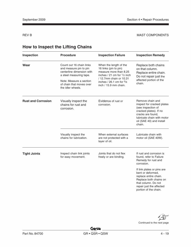
Section 4 • Repair Procedures
REV B
September 2009
Part No. 84700 GR • QSR • QSW 4 - 19
MAST COMPONENTS
How to Inspect the Lifting Chains
Inspection
Visually inspect thechains for rust andcorrosion.
Visually inspect thechains for lubrication.
Inspect chain link jointsfor easy movement.
Inspection Failure
Evidence of rust orcorrosion.
When external surfacesare not protected with alayer of oil.
Joints that do not flexfreely or are binding.
Inspection Remedy
Remove chain andinspect for cracked plates(see inspection ofcracked plates). If nocracks are found,lubricate chain with motoroil (SAE 40) and installchain.
Lubricate chain withmotor oil (SAE 40W).
If rust and corrosion isfound, refer to FailureRemedy for rust andcorrosion.
If link plates or pins arebent or deformed,replace entire chain.Replace both chains onthat column. Do notrepair just the affectedportion of the chain.
Wear
Rust and Corrosion
Tight Joints
Procedure
Count out 16 chain linksand measure pin to pincenterline dimension witha steel measuring tape.
Note: Measure a sectionof chain that moves overthe idler wheels.
When the length of the16 links (pin to pin)measure more than 8.25inches / 21 cm for 1/2 inch/ 12.7mm chain or 10.31inches / 26.1 cm for 5/8inch / 15.9 mm chain.
Replace both chainson that column.Replace entire chain.Do not repair just theaffected portion of thechain.
Continued to the next page

Section 4 • Repair Procedures
REV B
September 2009
4 - 20 GR • QSR • QSW Part No. 84700
MAST COMPONENTS
Inspection
Raised or Turned Pins
Chain Side
Chain Anchors
Idler Wheels
Cracked Link Plates
Procedure
Visually inspect for raisedpins.
Visually inspect forturned pins by insuringall the flats on the "V"heads are aligned.
Visually inspect for wearpatterns on heads of linkpins and outside linkplates where they contactthe idler wheel.
Visually inspect chainanchors.
chainanchors
threadedrod
Visually inspect chainidler wheels.
idler wheel
Visually inspect chain linkplates for cracks.
Inspection Failure
Raised pins.
Misalignment of flats onall "V" heads.
Wear on pin heads ornoticeable wear in theprofile of the outside linkplate.
link plate wear
Broken chain anchorfingers.
Bent or damaged anchor.
Twisted or misalignedchain anchor.
Threaded rod not visiblein inspection hole.
Idler wheels have badlyworn flanges.
Idler wheels havegrooves worn into chaincontact surface.
Cracks in any chain linkplate.
Inspection Remedy
Replace both chains onthat column section. Donot repair just theaffected portion of thechain.
Replace both chains onthat column section. Donot repair just theaffected portion of thechain.
Replace both chains onthat column section. Donot repair just theaffected portion of thechain.
Check alignment of chainanchors and idler wheels.
Replace chain anchor.
Replace chain anchor.
Replace chain anchorand threaded rod.
Re-align chain anchor toensure even loading ofchain.
Replace idler wheel andcheck chain alignment.
Replace idler wheel.
Replace both chains onthat column section.
Replace entire chain. Donot repair just theaffected portion of thechain.

Section 4 • Repair Procedures
REV B
September 2009
Part No. 84700 GR • QSR • QSW 4 - 21
MAST COMPONENTS
3-4Lift Cylinder
The lift cylinder is equipped with a normally closedsolenoid valve to prevent movement in the event ofa hydraulic line failure.
How to Remove the Lift CylinderBodily injury hazard. Thisprocedure requires specific repairskills, lifting equipment and asuitable workshop. Attempting thisprocedure without these skills andtools could result in death orserious injury and significantcomponent damage. Dealerservice is strongly recommended.
Note: When removing a hose assembly or fitting,the O-ring on the fitting and/or hose end must bereplaced and then torqued to specification duringinstallation. Refer to Section Two, Hydraulic Hoseand Fitting Torque Specifications.
1 Remove the mast. See 3-1, How to Remove theMast Assembly.
2 Rotate the mast until the carriage is facingdown.
3 Remove the socket head retaining fastenerfrom the clevis block on the lift cylinder rod endat the top of the number 1 column.
4 Remove the lift cylinder barrel end mountingfasteners.
5 Loosen the lift cylinder mounting bracketfasteners.
6 Support the cylinder and carefully slide it out ofthe mast assembly.
Crushing hazard. The lift cylindercould become unbalanced and fallif not properly supported whenremoved from the mast.
a
c
b
d
a top of number 1 columnb clevis block (not shown)c clevis block fastenerd lift cylinder (not shown)
e check valvef flow controlg cylinderh manual lowering valve
hfe g
M
LN

Section 4 • Repair Procedures
REV B
September 2009
4 - 22 GR • QSR • QSW Part No. 84700
Ground Controls
4-1Level Sensor
The Electronic Control Module (ECM) isprogrammed to deactivate the lift and drivefunctions and activate an alarm when a signal isreceived from the level sensor.
The tilt alarm sounds when the incline of thechassis exceeds 1.5° to the side, or 3° to the frontor rear.
How to Install and Calibrate theLevel Sensor
Tip-over hazard. Failure to installor calibrate the level sensor asinstructed will compromisemachine stability and cause themachine to tip over, resulting indeath or serious injury. Do notinstall or calibrate the level sensorother than specified in thisprocedure.
Note: Perform this procedure with the machine ona firm, level surface, free of obstructions.
Note: Perform this procedure with the platform inthe stowed position.
If you are not installing a new level sensor,proceed to step 6.
1 Tag and disconnect the level sensor wireharness from the chassis wire harness.
2 Remove the level sensor adjusting fasteners.Remove the level sensor from the machine.
3 Place the new level sensor onto the levelsensor base with the "X" on the level sensorclosest to the mast of the machine and the "Y"on the level sensor closest to the steer end ofthe machine.
Tip-over hazard. The level sensormust be installed with the "X" onthe level sensor closest to themast of the machine and the "Y"on the level sensor closest to thesteer end of the machine. Failureto install the tilt level sensor asinstructed could result in themachine tipping over, causingdeath or serious injury.
a chassisb level sensorc 'X' indicatord mast
a
b XY
b
c

Section 4 • Repair Procedures
REV B
September 2009
Part No. 84700 GR • QSR • QSW 4 - 23
GROUND CONTROLS
4 Install the level sensor adjusting fastenersthrough the level sensor and springs, and intothe mount. Tighten the fasteners and measurethe distance between the level sensor and thelevel sensor mount.
Result: The measurement should beapproximately 3/8 inch / 10 mm.
5 Connect the chassis wire harness to the levelsensor wire harness.
6 Tighten the level sensor adjusting fastenersuntil the bubble in the top of the level sensor iscentered in the calibration circles.
7 Turn the key switch to ground control and pullout the red Emergency Stop button to the onposition at both the ground and platformcontrols.
Result: The tilt sensor alarm should not sound.
8 Center a lifting jack under the drive chassis atthe ground controls side of the machine.
9 Raise the machine approximately2 inches / 5 cm.
10 GR-12, GR-15, QS-12R, QS-15R, QS-12W andQS-15W: Place a 0.65 x 6 x 6 inch / 1.65 x 15 x15 cm thick steel block under both wheels atthe ground controls side of the machine.
GR-20, QS-20R and QS-20W: Place a0.7 x 6 x 6 inch / 1.78 x 15 x 15 cm thick steelblock under both wheels at the ground controlsside of the machine.
11 Lower the machine onto the blocks.
12 Raise the platform approximately 1 foot / 30 cm.
Result: The level sensor alarm should notsound.
Result: The level sensor alarm does sound.Adjust the level sensor retaining fasteners justuntil the level sensor alarm does not sound.
13 Lower the platform to the stowed position.
14 Raise the machine slightly.
15 Remove the blocks from under both wheels.
16 Lower the machine and remove the jack.
17 Center a lifting jack under the drive chassis atthe tank side of the machine.
a adjusting fastenerb calibration circlesc ground controls
b ca

Section 4 • Repair Procedures
REV B
September 2009
4 - 24 GR • QSR • QSW Part No. 84700
GROUND CONTROLS
18 Raise the machine approximately2 inches / 5 cm.
19 GR-12, GR-15, QS-12R, QS-15R, QS-12W andQS-15W: Place a 0.79 x 6 x 6 inch / 2 x 15 x 15cm thick steel block under both wheels at thetank side of the machine.
GR-20, QS-20R and QS-20W: Place a0.85 x 6 x 6 inch / 2.16 x 15 x 15 cm thick steelblock under both wheels at the tank side of themachine.
20 Lower the machine onto the blocks.
21 Raise the platform approximately 1 foot / 30 cm.
Result: The platform should stop and an alarmshould sound.
Result: The platform does not stop or the levelsensor alarm does not sound. Adjust the levelsensor until the alarm just begins to sound ORthe down limit switch may need to be adjusted.
22 Lower the platform to the stowed position.
23 Raise the machine slightly.
24 Remove the blocks from under both wheels.
25 Lower the machine and remove the jack.
26 Center a lifting jack under the drive chassis atthe steer end of the machine.
27 Raise the machine approximately2 inches / 5 cm.
28 Place a 2.18 x 6 x 6 inch / 5.54 x 15 x 15 cmthick steel block under both wheels at the steerend of the machine.
29 Lower the machine onto the blocks.
30 Raise the platform approximately 1 foot / 30 cm.
Result: The level sensor alarm should notsound.
Result: The level sensor alarm does sound. Thelevel sensor is faulty and must be replaced.Repeat this procedure beginning with step 1.
31 Raise the machine slightly.
32 Remove the blocks from under both wheels.
33 Lower the machine and remove the jack.
34 Center a lifting jack under the drive chassis atthe non-steer end of the machine.
35 Raise the machine approximately2 inches / 5 cm.
36 Place a 2.4 x 6 x 6 inch / 6.1 x 15 x 15 cm thicksteel block under both wheels at the non-steerend of the machine.
37 Raise the platform approximately 1 foot / 30 cm.
Result: The platform should stop and an alarmshould sound.
Result: The platform does not stop or the levelsensor alarm does not sound. The level sensoris faulty and must be replaced. Repeat thisprocedure beginning with step 1.
38 Lower the platform to the stowed position.
39 Raise the machine slightly.
40 Remove the blocks from under both wheels.
41 Lower the machine and remove the jack.
Section 4 • Repair Procedures
REV A
September 2009
Part No. 84700 GR • QSR • QSW 4 - 25
Hydraulic Pump
5-1Function Pump
The hydraulic pump is attached to the motor whichmakes up the hydraulic power unit.
How to Test the Hydraulic PumpNote: When removing a hose assembly or fitting,the fitting and/or hose end must be torqued tospecification during installation. Refer to Section 2,Hydraulic Hose and Fitting Torque Specifications.
1 Tag, disconnect and plug the high pressurehydraulic hose from the hydraulic pump.
Bodily injury hazard. Sprayinghydraulic oil can penetrate andburn skin. Loosen hydraulicconnections very slowly to allowthe oil pressure to dissipategradually. Do not allow oil to squirtor spray.
2 Connect a 0 to 5000 psi / 0 to 350 bar pressuregauge to the high pressure port on the pump.
3 Turn the key switch to ground control and pullout the red Emergency Stop button to the onposition at both the ground and platformcontrols.
4 Activate the platform up function from theground controls.
Result: If the pressure gauge reads3200 psi / 221 bar, immediately stop. The pumpis good.
Result: If pressure fails to reach3200 psi / 221 bar, the pump is bad and willneed to be serviced or replaced.
Component damage hazard.There is no relief valve in thehydraulic pump and the pump canbe damaged if the pressure isallowed to exceed3200 psi / 221 bar. When testingthe pump, activate the pump inone second intervals until3200 psi / 221 bar is confirmed.Do not over-pressurize the pump.
5 Remove the pressure gauge and reconnect thehydraulic hose. Torque to specification.
Bodily injury hazard. Sprayinghydraulic oil can penetrate andburn skin. Loosen hydraulicconnections very slowly to allowthe oil pressure to dissipategradually. Do not allow oil to squirtor spray.

Section 4 • Repair Procedures
REV A
September 2009
4 - 26 GR • QSR • QSW Part No. 84700
How to Remove theHydraulic PumpNote: When removing a hose assembly or fitting,the O-ring on the fitting and/or hose end must bereplaced and then torqued to specification duringinstallation. Refer to Section Two, Hydraulic Hoseand Fitting Torque Specifications.
1 Tag, disconnect and plug the hydraulic supplyhard line at the pump. Cap the fitting on thepump.
2 Tag, disconnect and plug the high pressurehose at the pump. Cap the fitting on the pump.
Bodily injury hazard. Sprayinghydraulic oil can penetrate andburn skin. Loosen hydraulicconnections very slowly to allowthe oil pressure to dissipategradually. Do not allow oil to squirtor spray.
3 Remove the pump mounting bolts. Carefullyremove the pump.
Tip-over hazard. After replacingthe hydraulic pump, it is critical toreturn the function speed settingsto original factory specifications.Failure to restore the machine tooriginal factory specificationscould cause the machine to tipover, resulting in death or seriousinjury.
HYDRAULIC PUMP

Section 4 • Repair ProceduresSeptember 2009
Part No. 84700 GR • QSR • QSW 4 - 27
This page intentionally left blank.

Section 4 • Repair Procedures
REV B
September 2009
4 - 28 GR • QSR • QSW Part No. 84700
Function Manifold
Index SchematicNo. Description Item Function Torque
— Coil nut (items E, F and H) .......................................................................................................... 5 ft-lbs / 7 Nm
1 Diagnostic nipple ....................................... A ......................... Testing
2 Check disc ................................................. B ......................... Steer circuit ............................ 18 ft-lbs / 24 Nm
3 Relief valve,1800 to 3500 psi / 124 to 241 bar ............. C ......................... Lift relief .................................. 20 ft-lbs / 27 Nm
4 Check valve, 10 psi / 0.7 bar ..................... D ......................... Drive circuit ............................. 20 ft-lbs / 27 Nm
5 Solenoid valve, 3 position 4 way ............... E ......................... Drive forward/reverse ............. 25 ft-lbs / 34 Nm
6 Solenoid valve, 3 position 4 way ............... F ......................... Steer left/right ......................... 25 ft-lbs / 34 Nm
7 Flow regulator and relief valve,0.75 gpm / 2.8 L/min,1500 psi / 103 bar ...................................... G......................... Steer circuit ............................ 26 ft-lbs / 35 Nm
8 Solenoid valve, 2 position 4 way ............... H ......................... Platform up ............................. 25 ft-lbs / 34 Nm
9 Relief valve,3500 psi / 241 bar maximum ..................... I .......................... System relief ........................... 20 ft-lbs / 27 Nm
6-1Function Manifold Components
The function manifold is mounted next to the hydraulic power unit.

Section 4 • Repair Procedures
REV B
September 2009
Part No. 84700 GR • QSR • QSW 4 - 29
A
B
C
D
E
F
G
H
I
Y8
Y4
Y3
Y5
Y6
Note: 'alpha' callouts referto corresponding notes onthe hydraulic schematic
Note: 'alpha-numeric' calloutsrefer to corresponding noteson the electrical schematic
1 2
5
6
7
8
9
3
4
FUNCTION MANIFOLD

Section 4 • Repair Procedures
REV B
September 2009
4 - 30 GR • QSR • QSW Part No. 84700
6-2Valve Adjustments -Function Manifold
How to Adjust theSystem Relief ValveNote: Be sure that the hydraulic oil level is at theFULL mark on the hydraulic tank.
1 Locate the system relief valve on the functionmanifold (item I).
3 Chock both sides of the wheels at the steer endof the machine.
4 Remove the platform controls from the platform.
Note: Perform this test from the ground with theplatform controls. Do not stand in the platform.
5 Turn the key switch to platform control and pullout the red Emergency Stop button to the onposition at both the ground and platformcontrols.
6 Press and hold the function enable switch.
7 Move and hold the joystick fully in eitherdirection while observing the pressure readingon the pressure gauge. Note the pressure.Refer to Section 2, Specifications.
8 Turn the machine off. Hold the system reliefvalve with a wrench and remove the cap(schematic item I).
9 Adjust the internal hex socket. Turn it clockwiseto increase the pressure or counterclockwise todecrease the pressure.
Tip-over hazard. Failure to adjustthe relief valves to specificationcould result in the machine tippingover, causing death or seriousinjury. Do not adjust the reliefvalve pressures higher thanspecifications.
10 Install the relief valve cap.
11 Repeat steps 5 through 7 to confirm the reliefvalve pressure.
a
b
a test portb system relief valve
2 Connect a 0 to 5000 psi / 0 to 350 barpressure gauge to the test port on the functionmanifold (schematic item A).
FUNCTION MANIFOLD
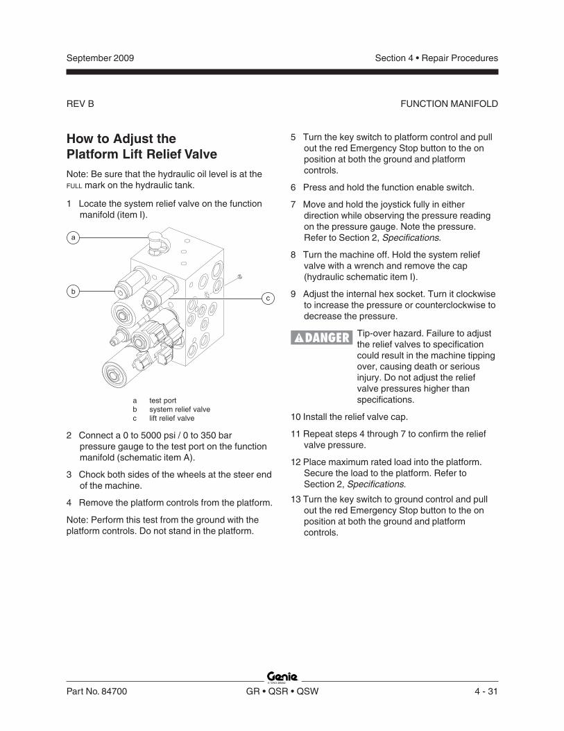
Section 4 • Repair Procedures
REV B
September 2009
Part No. 84700 GR • QSR • QSW 4 - 31
FUNCTION MANIFOLD
How to Adjust thePlatform Lift Relief ValveNote: Be sure that the hydraulic oil level is at theFULL mark on the hydraulic tank.
1 Locate the system relief valve on the functionmanifold (item I).
5 Turn the key switch to platform control and pullout the red Emergency Stop button to the onposition at both the ground and platformcontrols.
6 Press and hold the function enable switch.
7 Move and hold the joystick fully in eitherdirection while observing the pressure readingon the pressure gauge. Note the pressure.Refer to Section 2, Specifications.
8 Turn the machine off. Hold the system reliefvalve with a wrench and remove the cap(hydraulic schematic item I).
9 Adjust the internal hex socket. Turn it clockwiseto increase the pressure or counterclockwise todecrease the pressure.
Tip-over hazard. Failure to adjustthe relief valves to specificationcould result in the machine tippingover, causing death or seriousinjury. Do not adjust the reliefvalve pressures higher thanspecifications.
10 Install the relief valve cap.
11 Repeat steps 4 through 7 to confirm the reliefvalve pressure.
12 Place maximum rated load into the platform.Secure the load to the platform. Refer toSection 2, Specifications.
13 Turn the key switch to ground control and pullout the red Emergency Stop button to the onposition at both the ground and platformcontrols.
a test portb system relief valvec lift relief valve
2 Connect a 0 to 5000 psi / 0 to 350 barpressure gauge to the test port on the functionmanifold (schematic item A).
3 Chock both sides of the wheels at the steer endof the machine.
4 Remove the platform controls from the platform.
Note: Perform this test from the ground with theplatform controls. Do not stand in the platform.
a
bc

Section 4 • Repair Procedures
REV B
September 2009
4 - 32 GR • QSR • QSW Part No. 84700
14 Hold the lift relief valve with a wrench andremove the cap (schematic item C).
15 While activating the platform up function, adjustthe internal hex socket clockwise, just until theplatform fully raises.
16 Fully lower the platform.
17 Add an additional 50 pounds / 22.7 kg to theplatform. Secure the additional weight.
18 Attempt to raise the platform.
Result: The power unit should not be able to liftthe platform.
Result: If the power unit lifts the platform, adjustthe internal hex socket counterclockwise untilthe platform will not raise.
19 Install the relief valve cap.
20 Remove the weight from the platform.
21 Bleed the hydraulic system by raising theplatform to full height. If the pump cavitates orthe platform fails to reach full height, addhydraulic oil until the pump is functioningcorrectly. Do not overfill the hydraulic tank.
Component damage hazard. Donot continue to operate themachine if the hydraulic pump iscavitating.
How to Adjust the Steer ReliefValveNote: Be sure that the hydraulic oil level is at theFULL mark on the hydraulic tank.
1 Locate the steer relief valve on the functionmanifold (schematic item G).
a test portb steer relief valve
2 Connect a 0 to 5000 psi / 0 to 350 bar pressuregauge to the test port (schematic item A) on thefunction manifold.
3 Remove the platform controls from the platform.
Note: Perform this test from the ground with theplatform controls. Do not stand in the platform.
a
b
FUNCTION MANIFOLD

Section 4 • Repair Procedures
REV B
September 2009
Part No. 84700 GR • QSR • QSW 4 - 33
4 Turn the key switch to platform control and pullout the red Emergency Stop button to the onposition at both the ground and platformcontrols.
5 Activate the function enable switch and pressand hold the steer thumb rocker switch to theright. Allow the wheels to completely turn to theright. Continue holding the switch whileobserving the pressure reading on the pressuregauge. Note the pressure. Refer to Section 2,Specifications.
6 Press and hold the steer thumb rocker switch tothe left. Allow the wheels to completely turn tothe left. Continue holding the switch whileobserving the pressure reading on the pressuregauge.
7 Turn the machine off. Hold the steer relief valvewith a wrench and remove the cap (schematicitem G).
8 Adjust the internal hex socket. Turn it clockwiseto increase the pressure or counterclockwise todecrease the pressure.
Component damage hazard. Donot adjust the relief valvepressures higher thanspecifications.
9 Install the relief valve cap.
10 Repeat steps 5 through 6 to confirm the reliefvalve pressure.
FUNCTION MANIFOLD

Section 4 • Repair Procedures
REV B
September 2009
4 - 34 GR • QSR • QSW Part No. 84700
Valve Coil ResistanceSpecificationNote: The following coil resistance specificationsare at an ambient temperature of 68°F / 20°C. Asvalve coil resistance is sensitive to changes in airtemperature, the coil resistance will typicallyincrease or decrease by 4% for each 18°F / -7.7°Cthat your air temperature increases or decreasesfrom 68°F / 20°C.
Valve Coil Resistance Specifications
Description Specification
Solenoid valve, 3 position 4 way 27.2Ω20V DC with diode (schematic items E)
Solenoid valve, 3 position 4 way 19Ω20V DC with diode (schematic item F)
Solenoid valve, 2 position 4 way 25Ω20V DC with diode (schematic item H)
Solenoid valve, 2 position 2 way N.C. 6.25Ωwith manual override12V DC with diode (schematic item N)
6-3Valve Coils
How to Test a CoilA properly functioning coil provides anelectromagnetic force which operates the solenoidvalve. Critical to normal operation is continuitywithin the coil. Zero resistance or infiniteresistance indicates the coil has failed.
Since coil resistance is sensitive to temperature,resistance values outside specification canproduce erratic operation. When coil resistancedecreases below specification, amperageincreases. As resistance rises above specification,voltage increases.
While valves may operate when coil resistance isoutside specification, maintaining coils withinspecification will help ensure proper valve functionover a wide range of operating temperatures.
Electrocution/burn hazard. Contactwith electrically charged circuitscould result in death or seriousinjury. Remove all rings, watchesand other jewelry.
Note: If the machine has been in operation, allowthe coil to cool at least 3 hours before performingthis test.
1 Tag and disconnect the wiring from the coil tobe tested.
2 Test the coil resistance using a multimeter setto resistance (Ω). Refer to the Valve CoilResistance Specification table.
Result: If the resistance is not within theadjusted specification, plus or minus 10%,replace the coil.
FUNCTION MANIFOLD

Section 4 • Repair Procedures
REV B
September 2009
Part No. 84700 GR • QSR • QSW 4 - 35
FUNCTION MANIFOLD
a multimeterb 9V DC batteryc 10Ω resistord coil
Note: Dotted lines in illustration indicate areversed connection as specified in step 6
5 Momentarily connect the positive lead from themultimeter to the positive terminal on the 9Vbattery. Note and record the current reading.
6 At the battery or coil terminals, reverse theconnections. Note and record the currentreading.
Result: Both current readings are greater than0 mA and are different by a minimum of 20%.The coil is good.
Result: If one or both of the current readings are0 mA, or if the two current readings do not differby a minimum of 20%, the coil and/or itsinternal diode are faulty and the coil should bereplaced.
9VBATTERY
10
RESISTOR
�
MULTIMETER
COIL
+
-
+
-
d
b
b
a
c
c
How to Test a Coil DiodeGenie incorporates spike suppressing diodes in allof its coils. Properly functioning coil diodes protectthe electrical circuit by suppressing voltage spikes.Voltage spikes naturally occur within a functioncircuit following the interruption of electrical currentto a coil. Faulty diodes can fail to protect theelectrical system, resulting in a tripped circuitbreaker or component damage.
Electrocution/burn hazard. Contactwith electrically charged circuitscould result in death or seriousinjury. Remove all rings, watchesand other jewelry.
1 Test the coil for resistance. See 6-3, How toTest a Coil.
2 Connect a 10Ω resistor to the negative terminalof a known good 9V DC battery. Connect theother end of the resistor to a terminal on thecoil.
Note: The battery should read 9V DC or morewhen measured across the terminals.
Resistor, 10ΩΩΩΩΩGenie part number 27287
3 Set a multimeter to read DC amperage.
Note: The multimeter, when set to read DCamperage, should be capable of reading up to 800mA.
4 Connect the negative lead to the other terminalon the coil.
Note: If testing a single-terminal coil, connect thenegative lead to the internal metallic ring at eitherend of the coil.

Section 4 • Repair Procedures
REV A
September 2009
4 - 36 GR • QSR • QSW Part No. 84700
7-1Hydraulic Tank
The primary functions of the hydraulic tank are tocool and deaerate the hydraulic fluid duringoperation. It utilizes internal suction strainers forthe pump supply lines and has an external returnline filter.
How to Remove theHydraulic Tank
Component damage hazard. Thework area and surfaces where thisprocedure will be performed mustbe clean and free of debris thatcould get into the hydraulicsystem.
Note: When removing a hose assembly or fitting,the fitting and/or hose end must be torqued tospecification during installation. Refer to Section 2,Hydraulic Hose and Fitting Torque Specifications.
Note: Perform this procedure with the platform inthe stowed position.
1 Tag, disconnect and plug the hydraulic supplyhard line at the pump. Cap the fitting on thepump. Remove the hard line from the tank.
Hydraulic Tank
2 Tag, disconnect and plug the return hard line atthe hydraulic filter. Cap the fitting on the filter.
Bodily injury hazard. Sprayinghydraulic oil can penetrate andburn skin. Loosen hydraulicconnections very slowly to allowthe oil pressure to dissipategradually. Do not allow oil to squirtor spray.
3 Remove the hydraulic tank retaining fastenersand remove the hydraulic tank from themachine.
Torque specifications
Hydraulic tank retaining fasteners, dry 35 in-lbs4 Nm
Hydraulic tank retaining fasteners, lubricated 26 in-lbs2.9 Nm

Section 4 • Repair Procedures
REV A
September 2009
Part No. 84700 GR • QSR • QSW 4 - 37
Steer Axle Components
8-1Yoke and Drive Motor
How to Remove the Yokeand Drive Motor AssemblyNote: When removing a hose assembly or fitting,the fitting and/or hose end must be torqued tospecification during installation. Refer to Section 2,Hydraulic Hose and Fitting Torque Specifications.
1 Block the wheels at the non-steer end of themachine.
2 Remove the cotter pin from the wheel castle nutat the steer end of the machine.
Note: Always replace the cotter pin with a new onewhen removing the castle nut.
3 Loosen the wheel castle nut. Do not remove it.
4 Center a lifting jack under the drive chassis atthe steer end of the machine.
5 Raise the machine approximately6 inches / 15 cm. Place blocks under thechassis for support.
Crushing hazard. The chassiscould fall if not properly supported.
6 Remove the wheel castle nut. Remove thewheel.
7 Tag, disconnect and plug the hydraulic hoseson the drive motor. Cap the fittings on the drivemotor.
Bodily injury hazard. Sprayinghydraulic oil can penetrate andburn skin. Loosen hydraulicconnections very slowly to allowthe oil pressure to dissipategradually. Do not allow oil to squirtor spray.
Component damage hazard.Hoses can be damaged if they arekinked or pinched.
8 Support and secure the yoke assembly to anappropriate lifting device.
9 Remove the retaining fastener from the steerlink at the yoke assembly.
Note: Observe and note the quantity and locationof the spacers, when disconnecting the steer linkfrom the yoke assembly.
10 Remove the retaining fastener from the rear ofthe yoke pivot shaft.
Note: The pivot shaft retaining fastener is locatedbelow the main deck.
11 Lower the yoke assembly out of the chassis.
Bodily injury hazard. Theyoke/motor assembly may fall ifnot properly supported whenremoved from the machine.

Section 4 • Repair Procedures
REV A
September 2009
4 - 38 GR • QSR • QSW Part No. 84700
How to Remove a Drive Motor1 Block the wheels at the non-steer end of the
machine.
2 Remove the cotter pin from the wheel castle nutof the motor to be removed at the steer end ofthe machine.
Note: Always replace the cotter pin with a new onewhen removing the castle nut.
3 Loosen the wheel castle nut. Do not remove it.
4 Center a lifting jack under the drive chassis atthe steer end of the machine.
5 Raise the machine approximately2 inches / 5 cm. Place blocks under the chassisfor support.
Crushing hazard. The chassiscould fall if not properly supported.
6 Remove the wheel castle nut. Remove thewheel.
7 Tag, disconnect and plug the hydraulic hoseson the drive motor. Cap the fittings on the drivemotor.
Bodily injury hazard. Sprayinghydraulic oil can penetrate andburn skin. Loosen hydraulicconnections very slowly toallow the oil pressure todissipate gradually. Do notallow oil to squirt or spray.
Component damage hazard.Hoses can be damaged if they arekinked or pinched.
8 Remove the drive motor mounting fasteners.Remove the motor.
Torque specifications
Drive motor mounting fasteners, dry 75 ft-lbs101.7 Nm
Drive motor mounting fasteners, lubricated 56 ft-lbs76.3 Nm
STEER AXLE COMPONENTS

Section 4 • Repair Procedures
REV A
September 2009
Part No. 84700 GR • QSR • QSW 4 - 39
8-2Steer Cylinder
How toRemove the Steer CylinderNote: When removing a hose assembly or fitting,the O-ring on the fitting and/or hose end must bereplaced and then torqued to specification duringinstallation. Refer to Section Two, Hydraulic Hoseand Fitting Torque Specifications.
1 Block the wheels at the non-steer end of themachine.
2 Remove the steer cylinder hose guard bracketfrom the machine.
3 Remove the pin retaining fasteners from thesteer cylinder barrel-end pivot pin. Remove thepin.
Note: Observe and note the quantity and locationof the spacers when removing the pivot pin.
4 Remove the pin retaining fasteners from thesteer cylinder rod-end pivot pin. Remove thepin.
Note: Observe and note the quantity and locationof the spacers when removing the pivot pin.
5 Remove the steer cylinder from the machine.
6 Tag, disconnect and plug the hydraulic hosesfrom the steer cylinder. Cap the fittings.
Bodily injury hazard. Sprayinghydraulic oil can penetrate andburn skin. Loosen hydraulicconnections very slowly to allowthe oil pressure to dissipategradually. Do not allow oil tosquirt or spray.
Component damage hazard.Hoses can be damaged if they arekinked or pinched.
STEER AXLE COMPONENTS
8-3Steer Bellcrank
How toRemove the Steer Bellcrank1 Remove the steer cylinder. See 8-2, How to
Remove the Steer Cylinder.
2 Center a lifting jack under the drive chassis atthe steer end of the machine.
3 Raise the machine approximately14 inches / 36 cm. Place blocks under thechassis for support.
Crushing hazard. The chassiscould fall if not properly supported.
4 Turn the yokes fully to one side of the machine.
5 Remove the fasteners securing the bell crank tothe steer yoke.
Note: Observe and note the quantity and locationof the spacers between the bellcrank and the steerlinks.
6 Turn the yokes fully to the opposite side of themachine.
Note: Observe and note the quantity and locationof the spacers between the bellcrank and the steerlinks.
7 Remove the fasteners securing the bell crank tothe steer yoke.
8 Remove the bellcrank from the machine.
Note: Observe and note the quantity and locationof the spacers between the bellcrank and the steerlinks.

Section 4 • Repair Procedures
REV A
September 2009
4 - 40 GR • QSR • QSW Part No. 84700
9-1Drive Brake
How to Remove a Drive BrakeNote: When removing a hose assembly or fitting,the fitting and/or hose end must be torqued tospecification during installation. Refer to Section 2,Hydraulic Hose and Fitting Torque Specifications.
1 Block the wheels at the steer end of themachine.
2 Remove the cotter pin from the wheel castle nutat the non-steer end of the machine.
Note: Always replace the cotter pin with a new onewhen removing the castle nut.
3 Loosen the wheel castle nut. Do not remove it.
4 Center a lifting jack under the drive chassis atthe non-steer end.
5 Raise the machine approximately2 inches / 5 cm. Place blocks under the chassisfor support.
Crushing hazard. The chassiscould fall if not properly supported.
6 Remove the wheel castle nut. Remove thewheel.
7 Tag, disconnect and plug the hydraulic hosefrom the brake. Cap the fitting on the brake.
Bodily injury hazard. Sprayinghydraulic oil can penetrate andburn skin. Loosen hydraulicconnections very slowly to allowthe oil pressure to dissipategradually. Do not allow oil to squirtor spray.
8 Place a lifting jack under the brake for support.
9 Remove the fasteners that attach the brake tothe drive chassis. Remove the brake.
Crushing hazard. The brake willfall if not properly supported whenthe mounting fasteners areremoved.
Torque specifications
Brake mounting fasteners, dry 75 ft-lbs102 Nm
Brake mounting fasteners, lubricated 56 ft-lbs76 Nm
Non-steer Axle Components

Section 4 • Repair Procedures
REV A
September 2009
Part No. 84700 GR • QSR • QSW 4 - 41
Index SchematicNo. Description Item Function Torque
1 Hand pump ....................................... J ................ Manual brake release .............................. 30 ft-lbs / 41 Nm
2 Needle valve, pilot operated ............. K ............... Manual brake release enable .............. 45-50 in-lbs / 5 Nm
Brake Release Hand Pump Components
10-1Brake Release Hand Pump Components
The brake release hand pump manifold is mounted behind the hydraulic power unit.
J
K
Note: 'alpha' callouts referto corresponding notes onthe hydraulic schematic
1
2

Section 4 • Repair Procedures
REV B
September 2009
4 - 42 GR • QSR • QSW Part No. 84700
11-1Platform Overload System
Calibrate the Platform OverloadSystem (if equipped)Note: Perform this procedure with the machine ona firm, level surface.
1 Raise the platform approximately 2 feet / 70 cm.
2 Tag and disconnect the wire harness from theload sense limit switch.
Note: The load sense limit switch is located nearthe platform support.
3 Set a multi-meter to measure continuity.Connect the leads from the multi-meter to theblack and red wires disconnected from the limitswitch in step 2.
4 Determine the maximum platform capacity.Refer to the machine serial plate.
5 Using a suitable lifting device, place a testweight equal to that of the maximum platformcapacity at the center of the platform floor.Secure the weight to the platform. Refer to thechart below.
Standard Platform(GR-12 and GR-15 models) 227 kg(GR-20 models) 159 kg
Stockpicker Platform(GR-12, GR-15, QS-12R, QS-15R, QS-12Wand QS-15W models) 227 kg(GR-20, QS-20R and QS-20W models) 159 kg
Determine the limit switch trigger point:
6 Gently move the platform up and down by hand,so it bounces 1 to 2 inches / 2.5 to 5 cm.
7 Check the continuity between the black and redwires originating from the limit switch of theplatform overload assembly.
Result: There is no continuity. Slowly tightenthe load spring adjustment nut by turning itclockwise just until the limit switch closes andshows continuity.
Result: There is continuity. Slowly loosen theload spring adjustment nut by turning itcounterclockwise just until the limit switchopens and shows no continuity.
Note: The platform will need to be continuouslymoved up and down while making adjustments.
Fine adjustment of the switch trigger point:
8 Continue moving the platform up and down andadjust the load spring adjustment nut clockwiseor counterclockwise just until the limit switch isalternately opening and closing.
Note: When the limit switch is adjusted correctly,there will be continuity slightly longer than nocontinuity.
9 Remove the continuity tester from the limitswitch wires. Securely install the wires onto thelimit switch.
Platform Overload Components

Section 4 • Repair Procedures
REV B
September 2009
Part No. 84700 GR • QSR • QSW 4 - 43
Confirm the setting:
10 Turn the key switch to platform control.
11 Lift the test weight off the platform floor using asuitable lifting device.
12 Place the test weight back onto the platformfloor using a suitable lifting device.
Result: The diagnostic display at the groundcontrols will show two flat bars and a blinkinglight, indicating a normal condition, and thediagnostic display at the platform controls willshow the battery condition. Refer to Repairprocedure 1-3, How to Determine the BatteryVoltage.
13 Add an additional weight to the platform not toexceed 20% of the maximum rated load. Referto the machine serial plate.
Result: The diagnostic display will show 'OL' atboth the ground and platform controls. Theplatform overload system is operating properly.
Result: The diagnostic display at the groundcontrols will show two flat bars and a blinkinglight and the diagnostic display at the platformcontrols will show the battery condition. Theplatform overload system is not operatingproperly. Repeat this procedure beginning withstep 1.
14 Test all machine functions from the platformcontrols.
Result: All platform control functions should notoperate.
15 Turn the key switch to ground control.
16 Test all machine functions from the groundcontrols.
Result: All ground control functions should notoperate.
PLATFORM OVERLOAD COMPONENTS

Section 4 • Repair Procedures
REV A
September 2009
4 - 44 GR • QSR • QSW Part No. 84700
Obstruction Sensing System
12-1Obstruction Sensing Pads
The function of the Obstruction Sensing System isto detect a person or an object standing on themachine chassis. When a person or an object isdetected on top of the machine chassis, themachine platform down function will not operateand an alarm will sound.
How to Replace an ObstructionSensing Pad (QSR models only)1 Raise the platform approximately
5 feet / 152 cm.
2 Turn the key switch to the off position anddisconnect the battery pack from the machine.
Electrocution/burn hazard. Contactwith electrically charged circuitscould result in death or seriousinjury. Remove all rings, watchesand other jewelry.
3 At the non-steer end of the machine, unlatchthe covers and open the ground controls cover.
4 Working with the obstruction sensing pad to bereplaced, locate the pad cables.
5 Carefully pull the cables to identify theconnector cable located at the ground controls,non-steer end of the machine.
6 After the connector cable has been identified,tag and disconnect the cable from theobstruction sensing pad cables.
Note: If the ground controls side or battery boxcover obstruction sensing pad is replaced,carefully remove the appropriate pin from the maleDeutsch connector. A new Deutsch pin will have tobe installed onto the cable wire of the new groundcontrols side pad, or battery box cover pad.
7 Using a broad flat metal blade, carefully slidethe metal blade under the obstruction pad andwork the metal blade under the entire pad to bereplaced, until the pad is separated from thechassis or the battery box cover.
8 Remove the pad from the machine and carefullyscrape away any excess adhesive from thechassis or battery box cover.
9 Using a suitable solvent, clean the surface werethe obstruction sensing pad was removed.Allow the surface to dry thoroughly.
10 Install the new obstruction sensing pad.
Note: It may be necessary to use touch-up paint inthe area were the obstruction sensing pad wasremoved. Let the paint dry completely, beforeinstalling the new obstruction sensing pad.

Section 4 • Repair Procedures
REV A
September 2009
Part No. 84700 GR • QSR • QSW 4 - 45
OBSTRUCTOION SENSING PADS
d
e
f
c
Ground Controls SideHydraulic Tank SideNon-steer End
Steer End
a
b
Obstruction Sensing Pads
a cable connectorsb Deutsch connectorc battery box
obstruction sensing padd ground controls side
obstruction sensing pade steer end
obstruction sensing padf hydraulic tank side
obstruction sensing pad

Section 4 • Repair Procedures September 2009
4 - 46 GR • QSR • QSW Part No. 84700
This page intentionally left blank.

Section 5 • Fault CodesSeptember 2009
Part No. 84700 GR • QSR • QSW 5 - 1
Before Troubleshooting:
Read, understand and obey the safety rulesand operating instructions in the appropriateoperator's manual on your machine.
Be sure that all necessary tools and testequipment are available and ready for use.
Be aware of the following hazards and followgenerally accepted safe workshop practices.
Crushing hazard. When testingor replacing any hydrauliccomponent, always supportthe structure and secure itfrom movement.
Electrocution/burn hazard.Contact with electrically chargedcircuits could result in death orserious injury. Remove all rings,watches and other jewelry.
Bodily injury hazard. Sprayinghydraulic oil can penetrate andburn skin. Loosen hydraulicconnections very slowly to allowthe oil pressure to dissipategradually. Do not allow oil tosquirt or spray.
Fault Codes
Observe and Obey:
Troubleshooting and repair procedures shall becompleted by a person trained and qualified onthe repair of this machine.
Immediately tag and remove from service adamaged or malfunctioning machine.
Repair any machine damage or malfunctionbefore operating the machine.
Unless otherwise specified, perform eachrepair procedure with the machine in thefollowing configuration:
· Machine parked on a firm, level surface
· Platform in the stowed position
· Key switch in the off position with the keyremoved
· The red Emergency Stop button in the offposition at both ground and platform controls
· Wheels chocked
· All external AC power supply disconnectedfrom the machine

Section 5 • Fault Codes September 2009
5 - 2 GR • QSR • QSW Part No. 84700
REV C
General Repair Process
About This SectionWhen a malfunction is discovered, the fault codechart in this section will help a service professionalpinpoint the cause of the problem. To use thissection, basic hand tools and certain pieces of testequipment are required—voltmeter, ohmmeter,pressure gauges.
Malfunctiondiscovered
Identifysymptoms
Troubleshoot
Performrepair
Return toservice problem
solved
problemstill exists
Inspectand test
LED Diagnostic Readout
FAULT CODES
The diagnostic readout displays numerical codesthat provide information about the machineoperating status and about malfunctions. The dotto the right of the numbers remain on when afault code is displayed.
The codes listed in the Fault Code Chartdescribe malfunctions and can aid introubleshooting the machine by pinpointing thearea or component affected.

Section 5 • Fault CodesSeptember 2009
Part No. 84700 GR • QSR • QSW 5 - 3
REV CFault Code Chart
Fault Code Problem Possible Causes Solution
01 Internal ECM error. EPROM not programmed. Replace ECM.
02 ECM/Platform communication error.
Malfunctioning control cable OR malfunctioning platform controls.
Troubleshoot control cable OR troubleshoot platform controls.
03 Undefined platform DIP switch settings.
DIP switch settings incorrect.
Correct DIP switch settings.
12 Chassis up/down toggle closed at start up.
Malfunctioning up/down switch.
Troubleshoot up/down switch.
18 Pothole guard failure. Malfunctioning pothole switch OR obstruction in pothole guard linkage.
Troubleshoot pothole switch OR remove obstruction.
19 Limit switch failure. Malfunctioning limit switch OR wire disconnected from limit switch.
Troubleshoot limit switch OR inspect wire connection.
42 Platform left turn switch fault.
Malfunctioning steer left microswitch.
Troubleshoot steer left microswitch.
43 Platform right turn switch fault.
Malfunctioning steer right microswitch.
Troubleshoot steer right microswitch.
46 Platform drive enable switch fault.
Malfunctioning drive enable switch.
Troubleshoot drive enable switch.
47 Platform joystick fault. Joystick potentiometer not centered.
Verify potentiometer setting.
52 Forward coil fault. Malfunctioning coil OR wire disconnected from coil.
Troubleshoot coil OR inspect wire connection.
53 Reverse coil fault. Malfunctioning coil OR wire disconnected from coil.
Troubleshoot coil OR inspect wire connection.
54 Up coil fault. (Not used on GS-3232)
Malfunctioning coil OR wire disconnected from coil.
Troubleshoot coil OR inspect wire connection.
55 Down coil fault OR Obstruction sensing system error
Malfunctioning coil OR wire disconnected from coil. Person OR object detected on the obstruction sensing pads.
Troubleshoot coil OR inspect wire connection. Clear the obstruction sensing pads of personnel OR objects.
56 Steer right coil fault. Malfunctioning coil OR wire disconnected from coil.
Troubleshoot coil OR inspect wire connection.
57 Steer left coil fault. Malfunctioning coil OR wire disconnected from coil.
Troubleshoot coil OR inspect wire connection.
58 Brake coil fault. Malfunctioning coil OR wire disconnected from coil.
Troubleshoot coil OR inspect wire connection.
59 Series/parallel coil fault. DIP switch settings are incorrect.
Troubleshoot and correct DIP switch settings.
68 Low battery voltage. Batteries discharged. Charge batteries.
LL Off level fault. Tilt of chassis exceeds level sensor setting
Reduce chassis angle.
OL Overload cutout fault. Too much weight in platform
Remove weight.

Section 5 • Fault Codes September 2009
5 - 4 GR • QSR • QSW Part No. 84700
This page intentionally left blank.
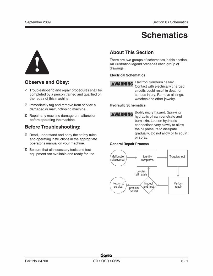
Section 6 • SchematicsSeptember 2009
Part No. 84700 GR • QSR • QSW 6 - 1
Schematics
Observe and Obey:
Troubleshooting and repair procedures shall becompleted by a person trained and qualified onthe repair of this machine.
Immediately tag and remove from service adamaged or malfunctioning machine.
Repair any machine damage or malfunctionbefore operating the machine.
Before Troubleshooting:
Read, understand and obey the safety rulesand operating instructions in the appropriateoperator's manual on your machine.
Be sure that all necessary tools and testequipment are available and ready for use.
About This SectionThere are two groups of schematics in this section.An illustration legend precedes each group ofdrawings.
Electrical Schematics
Electrocution/burn hazard.Contact with electrically chargedcircuits could result in death orserious injury. Remove all rings,watches and other jewelry.
Hydraulic Schematics
Bodily injury hazard. Sprayinghydraulic oil can penetrate andburn skin. Loosen hydraulicconnections very slowly to allowthe oil pressure to dissipategradually. Do not allow oil to squirtor spray.
General Repair Process
Malfunctiondiscovered
Identifysymptoms
Troubleshoot
Performrepair
Return toservice problem
solved
problemstill exists
Inspectand test

Section 6 • Schematics September 2009
REV C
6 - 2 GR • QSR • QSW Part No. 84700
Electrical Component and Wire Color Legends
ELECTRICAL COMPONENT LEGEND Item Description B5 Battery
Button BN BN5 = Horn BN6 = High torque BN8 = Drive enable
BN9 = Lift enable C5 Capacitor, 4700 uF CB2 Circuit breaker, 7A
Control relay CR CR5 = Horn relay (with H2 option) CR27A = Overload (motor controller) (option) CR27B = Overload (load sense) (option) CR27C = Overload (down coil) (option) CR48 = Power relay to U5 (e-stop) CR58 = Keypad relay (Keypad option) CR111A = Obstruction sensing (QS retail) CR111B = Obstruction sensing (QS retail)
D7 Voltage regulator (Platform controls circuit board) EN4 Enclosure - AC outlet box F6 Fuse, 275A FB Flashing beacons
Gauge G G6 = Hour meter G8 = Diagnostic display
GND Ground Horn or alarm H H1 = Horn H2 = Automotive-style horn (option) H5 = Multifunction alarm H10 = Obstruction sensing (QS retail)
JC1 Joystick controller KS1 Key switch
LED or light L L16 = Lift L17 = Drive L21 = High torque Limit switch LS LS6 = Platform down LS7 = Pothole LS8 = Pothole LS19 = Load sense (option)
M5 Hydraulic power unit NC Normally closed NO Normally open NCHO Normally closed held open
ELECTRICAL COMPONENT LEGEND Item Description
Power switch P P1 = Emergency Stop button at ground controls P2 = Emergency Stop button at platform controls Quick disconnect QD QD1 = Battery quick disconnect QD3 = Control cable to ground QD4 = Control cable to platform
R Resistor 25 Ohm/25Watt (QS retail) Switch SW SW5 = Function enable SW6 = Steer left/right
S7 Tilt level sensor TS66 Platform up/down toggle switch
Electronic component U U3 = Platform controls printed circuit board U5 = Electronic control module U6 = Motor controller U9 = Battery charger U13 = Voltage inverter (option) U38 = Keypad (option) U47A = Obstruction sensing pad (hydraulic tank side) (QS retail) U47B = Obstruction sensing pad (battery tray) (QS retail) U47C = Obstruction sensing pad (steer end) (QS retail) U47D = Obstruction sensing pad (ground controls side) (QS retail) Valve coil Y Y3 = Steer right Y4 = Steer left Y5 = Drive reverse Y6 = Drive forward Y7 = Platform down Y8 = Platform up
WIRE COLOR LEGEND Color Description BK Black BK/WH Black/White BL Blue BL/BK Blue/Black BN Brown GN Green GN/BK Green/Black GN/YL Green/Yellow GY Gray LB Light Blue OR Orange OR/BK Orange/Black PP Purple RD Red RD/BK Red/Black WH White WH/BK White/Black YL Yellow

Section 6 • SchematicsSeptember 2009
REV B
Part No. 84700 GR • QSR • QSW 6 - 3
A 12
B
C
1
1
1
12
1212
ECM PIN-OUT LEGEND Item Description A1 Flashing beacon FB1 (output) A2 Ground from platform controls (input)
(White wire at platform controls) A3 Plug A4 Driver Power (input) A5 Level sensor power S7 (output) A6 Platform up coil Y8 (output) A7 Drive reverse coil Y5 (output) A8 Motor controller U6, terminal 1 A9 Motor controller U6, terminal 3 A10 Overload sensor PS2 (input) A11 Key switch to platform control (input) A12 Platform down TS66 (input) B1 Platform data link (high) (input)
(Blue wire at platform controls) B2 Plug B3 ECM ground (output) B4 Plug B5 Plug B6 Platform down coil Y7 (output) B7 Steer left coil Y4 (output) B8 Automotive-style horn H2 (option) (output) B9 Multi-function alarm H5 (output) B10 Pothole limit switch (input) B11 Drive enable power/up limit switch (input) B12 Platform up TS66 (input) C1 Platform data link (low) (input)
(Orange wire at platform controls) C2 Power to ECM (input) C3 Plug C4 Plug C5 Jumper C6 Drive forward coil Y6 (output) C7 Steer right coil Y3 (output) C8 Plug C9 Plug C10 Jumper C11 Level sensor signal S7 (input) C12 Down limit switch LS66 (input)
ECM Pin-out Legend

Section 6 • Schematics September 2009
REV C
6 - 4 GR • QSR • QSW Part No. 84700
Relay Layout
Relay Layout - GR and QSW
a platform overload CR27A(motor cont) (option)
b platform overload CR27B(load sense) (option)
c platform overload CR27C(down coil) (option)
d auto-style horn CR5 (option)e power relay CR48f ECM diagnostic display windowg electronic control module (ECM) U5h motor controller U6
a b c d e
h g f
Relay Layout - QSR
a resistor 25 ohm/25 wattb obstruction sensing CR111A
(QS retail)c obstruction sensing alarmd obstruction sensing CR111B
(QS retail)e auto-style horn CR5 (option)f power relay CR48g ECM diagnostic display windowh electronic control module (ECM) U5i motor controller U6
fedba
i gh
c

Section 6 • SchematicsSeptember 2009
REV B
Part No. 84700 GR • QSR • QSW 6 - 5
Wiring DiagramGround and Platform Controls
H1ALARM
RD
BK
1 4.2 5.
2 1N
CP2EMERGENCY
STOP
JC1JOYSTICKCONTROLLER
RD
BK
OR
WH
WH
/BL
PP
BL
GY
BN
YL
GY
WH
RD
BL
OR
TO COIL CORD
RD
BK
PLATFORM CONTROLS
RDBK
CR48TERMINAL 30
ECM PIN A11
ECM PIN B12
ECM PIN A12
MOTOR CONTROLLERTERMINAL B+
MOTOR CONTROLLERTERMINAL 1
6-PIN CONNECTORPIN 1
OR
RD
BL
WH
BK
BN
RD
P1EMERGENCY STOP
TS66PLATFORM UP/DOWNTOGGLE SWITCH
CB27A CIRCUITBREAKER
KS1KEY SWITCH
GROUND CONTROLS
B
13
4 2
B1
(UP)
(DOWN)
NC1 2

Section 6 • Schematics September 2009
REV B
6 - 6 GR • QSR • QSW Part No. 84700
-
+
U9
CB2
N.C.H.O.N.C.B+
3A2
T2
B- 1
87A 85
8630
87
A1
D1
M5
N.O.
S7LEVEL
SENSOR
LEVEL SENSORCIRCUIT BOARD
JC1JOYSTICK
CONTROLLER
HALLGENERATOR
SW6STEER LEFT/ RIGHT
LE
FT
RIG
HTSW5
FUNCTIONENABLE
PLATFORMCONTROL
GROUNDCONTROL
B
B1
3
4
2
1
KS1KEYSWITCH
ORWH
RD
MO
TO
R C
ON
TR
. EN
AB
LE
N.C.
N.O.
Electrical Symbols Legend
Wire withdescription or color
Circuits crossingno connection
Diode
Circuit connection
Connector
Hour meter
Flashing beacon
Limit switch
Button or switch
Toggle switch
Emergency Stop button
Circuit breaker
Control relay
Fuse
Horn or alarm
LED
Motor controller
Motor
Battery charger
6V DC battery
Level sensor
Solenoid valve with diode
Capacitor
Resistor
Pressure Switch
Key switch
Joystick

Section 6 • SchematicsSeptember 2009
Part No. 84700 GR • QSR • QSW 6 - 7
This page intentionally left blank.

Section 6 • Schematics September 2009
REV C
6 - 8 GR • QSR • QSW Part No. 84700
Electrical Schematic - GR and QSWANSI and CSA ModelsPart 1 of 2

Section 6 • SchematicsSeptember 2009
REV C
Part No. 84700 GR • QSR • QSW 6 - 9
Electrical Schematic - GR and QSWANSI and CSA Models
Part 2 of 2

Section 6 • Schematics September 2009
REV D
6 - 10 GR • QSR • QSW Part No. 84700
Electrical Schematic - GR and QSWCE ModelsPart 1 of 3

Section 6 • SchematicsSeptember 2009
REV D
Part No. 84700 GR • QSR • QSW 6 - 11
Electrical Schematic - GR and QSWCE ModelsPart 2 of 3

Section 6 • Schematics September 2009
REV D
6 - 12 GR • QSR • QSW Part No. 84700
Electrical Schematic - GR and QSWCE ModelsPart 3 of 3

Section 6 • SchematicsSeptember 2009
Part No. 84700 GR • QSR • QSW 6 - 13
This page intentionally left blank.

Section 6 • Schematics September 2009
REV A
6 - 14 GR • QSR • QSW Part No. 84700
Electrical Schematic - QSRANSI and CSA ModelsPart 1 of 3
INB11
WH
H2AUTO-STYLEHORN(OPTION)
U6MOTOR
CONTROLLER
B+
3A2
M
B- 1
QD1 +( )
M5MOTOR
A1
D1
M5
B54-6V
BATTERY
U9BATTERYCHARGER
ACINPUT
+
-
-
+
+
-
-
+
CR5HORN RELAY(H2 OPTION)
87
30
85
86
U13DC/AC INVERTER(OPTION)
A8 OUT
B8OUT
A1 OUT
FBFLASHINGBEACONS(OPTION)
P1EMERGENCY
STOP
U5ELECTRONIC CONTROL MODULE
PLATFORMCONTROL
GROUNDCONTROL
B
B1
3
4
2
1
KS1KEY SWITCH
ORWH
LS7POTHOLE
GUARDSWITCH
LS8POTHOLE
GUARDSWITCH
INB10
H5ALARM
OUTB9
+
-
N.C.H.O.
N.C.H.O.
BL
RD
OR
BK
WH
IN INA12 B12
INA11
TS66PLATFORMUP/DOWN
UP
DO
WN
OR
RD
BL
B3OUT
BN
C7 B7 A7OUT OUT OUT
Y3STEERRIGHT
Y4STEER
LEFT
Y5DRIVE
REVERSE
BLBL
/BK
WH
/BK
TO A(QUICK DISCONNECT)
AC INPUT
POWER TO PLATFORM
(110V-240V AC)
F6 275A FUSE
RD
RD
A9 OUTGN
ES0126E
- NOTE -MACHINE SHOWNIN THE STOWEDPOSITION WITH
THE POWER OFF
GROUND
CONTROLSCB2
7ACIRCUIT
BREAKER
G6HOUR
METER
QD1 -( )
A4IN
WH
LS6DOWN
LIMITSWITCH
INC12
N.C.H.O.
RD
UP
/DO
WN
SW
DW
N
UP
/DO
WN
SW
UP
KE
YS
WIT
CH
AL
AR
M
PO
TH
OL
E L
IMIT
SW
ITC
H
DR
IVE
R P
OW
ER
DO
WN
LIM
IT
WH
WH
RD
BK
BK EC
M G
RO
UN
D

Section 6 • SchematicsSeptember 2009
REV A
Part No. 84700 GR • QSR • QSW 6 - 15
Electrical Schematic - QSRANSI and CSA Models
Part 2 of 3
INC2
WH
GND
GN
D F
RO
M J
OY
ST
ICK
INA2
INC11 A5
RD
WH
BK
N.C.
S7LEVEL
SENSOR
LEVELSENSORCIRCUITBOARD
3
1
2
5
4
DA
TA
LIN
K (L
OW
)
DA
TA
LIN
K (H
IGH
)
IN INB1 C1
3
1
2
5
4
QD4
WH/BK
BL
RD
OR
OR/BK
WH
/BK
BL
OR
GN
RD
66
A
YL
BL
RD
OR
WH
U5ELECTRONIC CONTROL MODULE
OUT
CR48POWERRELAY TO U5(E-STOP)
8587
8630 4
3
1
2
GN
WH
BK
3
1
2
LB
GN/YL
BK
QD4A
RD/BK
Y6DRIVE
FORWARD
Y7PLATFORM
DOWN
Y8PLATFORM
UP
C6OUT
WH
A6OUT
BK
/WH
B6OUT
GN
/BK
ES0126E
EC
M P
OW
ER
LE
VE
LS
NS
R - W
H
LE
VE
LS
NS
R - R
D
-+
8587
8630
87a
R2725 OHMS25 WATT
H10OBSTRUCTION
SENSINGALARM
CR111BOBSTRUCTIONSENSING8587
8630
87a
CR111AOBSTRUCTIONSENSING
(OBSTRUCTION SENSING )QS RETAIL
YL
BN
OROR
OR
WH
WH
RD
RD
BN
OR
BL
GN/YL
TO A(JUNCTION BOX)
BK
BL
- NOTE -MACHINE SHOWNIN THE STOWEDPOSITION WITH
THE POWER OFF

Section 6 • Schematics September 2009
REV A
6 - 16 GR • QSR • QSW Part No. 84700
Electrical Schematic - QSRANSI and CSA ModelsPart 3 of 3
DATA LINK (LOW)
DATA LINK (HIGH)
GROUND
POWER TO GROUND
POWER TO PLATFORMBK
3 3 RD
4 4
WH1 1
BL2 2
OR5 5
QD3
BK
BL
RD
OR
WH
LB
GN/YL
BKAC
OUTLET
YL
BL
RD
OR
WH
EN4AC
OUTLET
BOX
BK
BL
RD
OR
WH
RD/BK
PLATFORM
CONTROLLER
HORN BN5
DRIVE ENABLE BN8
HIGH TORQUE BN6PIN1
PIN2
PIN3
LIFT ENABLE BN9PIN4
DRIVE LED L17
LIFT LED L16
POUT2
POUT3 HIGH TORQUE LED L21
POUT1
PLATFORM CONTROLSMEMBRANE DECAL
H1ALARM
POUT11
PIN11
RD +
-BK
BK
P2EMERGENCY
STOPBK
RD
PIO3
PIO5
PIO4
D7VOLTAGE
REGULATOR
5V DC
24V DC
PIO2
U3PLATFORM CONTROLS
PRINTED CIRCUIT BOARD
GY
GN
BN
WH
PP
PIN8
PIN10
PIN9OR
BK
RD
JC1JOYSTICK
CONTROLLER
BL
SW6STEER
LEFT/ RIGHT
LE
FT
RIG
HT
SW5FUNCTION ENABLE
HALL EFFECTGENERATOR
POUT4G8
DIAGNOSTICDISPLAY
- NOTE -MACHINE SHOWNIN THE STOWEDPOSITION WITH
THE POWER OFF
U47AOBSTRUCTION SENSINGPAD (Hydraulic Tank Side)
U47BOBSTRUCTION SENSINGPAD (Battery Tray)
U47COBSTRUCTION SENSINGPAD (Steer End)
U47DOBSTRUCTION SENSINGPAD (Ground Controls Side)
(OBSTRUCTION SENSING QS RETAIL)
WH
RD
OR
BL
BL
BN
BN
BL
A
ES0126E

Section 6 • SchematicsSeptember 2009
Part No. 84700 GR • QSR • QSW 6 - 17
This page intentionally left blank.

Section 6 • Schematics September 2009
REV A
6 - 18 GR • QSR • QSW Part No. 84700
Electrical Schematic - QSRCE ModelsPart 1 of 3
C7 B7OUT OUT
Y3STEERRIGHT
Y4STEER
LEFT
BLBL
/BK
INB11
G6HOUR
METER
H2AUTO-STYLEHORN(OPTION)
U6MOTOR
CONTROLLER
B+
3A2
T2
B- 1
QD1 +( )
M5MOTOR
A1
D1
M5
B54-6V
BATTERY
U9BATTERYCHARGER
ACINPUT
QD1 -( )
+
-
-
+
+
-
-
+
CR5HORN RELAY(H2 OPTION)
87
30
85
86
U13DC/AC INVERTER(OPTION)
CB27A
CIRCUITBREAKER
A8 OUT
B8OUT
A1 OUT
FBFLASHINGBEACONS(OPTION)
P1EMERGENCY
STOP
U5ELECTRONIC CONTROL MODULE
PLATFORMCONTROL
GROUNDCONTROL
B
B1
3
4
2
1
KS1KEY SWITCH
ORWH
LS7POTHOLE
GUARDSWITCH
LS8POTHOLE
GUARDSWITCH
INB10
H5ALARM
OUTB9
+
-
N.C.H.O.
N.C.H.O.
BL
RD
OR
BK
WH
IN INA12 B12
INA11
TS66PLATFORMUP/DOWN
UP
DO
WN
OR
RD
BL
B3OUT
BN
TO A(QUICK DISCONNECT)
LS6DOWN
LIMITSWITCH
INC12
N.C.H.O.
RDF6 275A FUSE
RD
RD
GROUND
CONTROLSAC INPUT
POWER TO PLATFORM
(110V-240V AC)
- NOTE -MACHINE SHOWNIN THE STOWEDPOSITION WITH
THE POWER OFF
ES0127F
A4IN
WH
WH
WH
BK
BK
WH
DR
IVE
R P
OW
ER
KE
YS
WIT
CH
RD
EC
M G
RO
UN
D
UP
/DO
WN
SW
DW
N
UP
/DO
WN
SW
UP
AL
AR
M
PO
TH
OL
E L
IMIT
SW
ITC
H
DO
WN
LIM
IT

Section 6 • SchematicsSeptember 2009
REV A
Part No. 84700 GR • QSR • QSW 6 - 19
Electrical Schematic - QSRCE ModelsPart 2 of 3
GN/YL
INC2
WH
A7OUT
Y5DRIVE
REVERSE
Y6DRIVE
FORWARD
Y7PLATFORM
DOWN
Y8PLATFORM
UP
GND
U5ELECTRONIC CONTROL MODULE
WH
/BK
GN
D F
RO
M J
OY
ST
ICK
INA2
INC11 A5
RD
WH
BK
N.C.
S7LEVEL
SENSOR
LEVELSENSORCIRCUITBOARD
3
1
2
5
4
DA
TA
LIN
K (L
OW
)
DA
TA
LIN
K (H
IGH
)
IN INB1 C1
3
1
2
5
4
QD4
WH/BK
BL
RD
OR
OR/BK
WH
/BK
BL
OR
GN
RD
C6OUT
WH
A6OUT
BK
/WH
CR48POWERRELAY TO U5(E-STOP)
CR27AOVERLOAD
(MOTOR CONT)
OUTA9
8587
8630
CR27COVERLOAD(DOWN COIL)
OUTB6
8587
8630
INA10
CR27BOVERLOAD(LOAD SENSE)
8587A
86301 2 3
8587
8630 4
GN
WH
GN
/BK
C54700 uF
66
A
YL
BL
RD
OR
WH
INC5
WH
INC10
OUT
BL/BK
3
1
2
GN
WH
BK
3
1
2
LB
GN/YL
BK
QD4A
RD/BK
TO A(JUNCTION BOX)
ES0127F
EC
M P
OW
ER
-+
8587
8630
87a
R2725 OHMS25 WATT
H10OBSTRUCTION
SENSINGALARM
CR111BOBSTRUCTIONSENSING8587
8630
87a
CR111AOBSTRUCTIONSENSING
(OBSTRUCTION SENSING QS RETAIL)
FOR OBSTRUCTION SENSING SYSTEMA-B IS OPEN, CLOSED OTHERWISE
YL
BN
OR
OR
OR
WH
WH
RD
RD
BN
OR
BL
BK
- NOTE -MACHINE SHOWNIN THE STOWEDPOSITION WITH
THE POWER OFF
OR

Section 6 • Schematics September 2009
REV A
6 - 20 GR • QSR • QSW Part No. 84700
Electrical Schematic - QSRCE ModelsPart 3 of 3
A
LB
BKAC
OUTLET
OR
RD
YL
BL
RD
OR
WH
BKEN4AC OUTLET BOX
RD/BK WH
BK
BL
RD
OR
WH
LS19LOAD
SENSELIMIT
SWITCH
BK
WHN.C.
N.O.
RD
OR
DATA LINK (LOW)
DATA LINK (HIGH)
GROUND
POWER TO GROUND
POWER TO PLATFORMBK
3 3 RD
4 4
WH1 1
BL2 2
OR5 5
QD3
BK
BL
RD
OR
WH
- NOTE -MACHINE SHOWNIN THE STOWEDPOSITION WITH
THE POWER OFF ES0127F
PLATFORM
CONTROLLER
HORN BN5
DRIVE ENABLE BN8
HIGH TORQUE BN6PIN1
PIN2
PIN3
LIFT ENABLE BN9PIN4
DRIVE LED L17
LIFT LED L16
POUT2
POUT3 HIGH TORQUE LED L21
POUT1
PLATFORM CONTROLSMEMBRANE DECAL
H1ALARM
POUT11
PIN11
RD +
-BK
BK
P2EMERGENCY
STOPBK
RD
PIO3
PIO5
PIO4
D7VOLTAGE
REGULATOR
5V DC
24V DC
PIO2
U3PLATFORM CONTROLS
PRINTED CIRCUIT BOARD
GY
GN
BN
WH
PP
PIN8
PIN10
PIN9OR
BK
RD
JC1JOYSTICK
CONTROLLER
BL
SW6STEER
LEFT/ RIGHT
LE
FT
RIG
HT
SW5FUNCTION ENABLE
HALL EFFECTGENERATOR
POUT4G8
DIAGNOSTICDISPLAY
8587
8630G
N
WH
RD
RD
WH
GN
RD
BL
GN/YL
1
2
3
4
5
6
7
8
9
0
LOCK
(KEYPAD OPTION)
FOR UK PLUG OPTION, GN/YL GROUNDWIRE CONNECTS TO OUTLET BOXGROUND SCREW AND OUTLET PLUGGROUND TERMINAL.
NOT CONNECTEDHERE WHEN KEYPADOPTION IS INSTALLED
CR58KEYPADRELAY
U38KEYPAD
GN/YL
U47AOBSTRUCTION SENSINGPAD (Hydraulic Tank Side)
U47BOBSTRUCTION SENSINGPAD (Battery Tray)
U47COBSTRUCTION SENSINGPAD (Steer End)
U47DOBSTRUCTION SENSINGPAD (Ground Controls Side)
(OBSTRUCTION SENSING QS RETAIL)
WH
RD
OR
BL
BL
BN
BN
BL

Section 6 • SchematicsSeptember 2009
Part No. 84700 GR • QSR • QSW 6 - 21
This page intentionally left blank.

Section 6 • Schematics September 2009
REV A
6 - 22 GR • QSR • QSW Part No. 84700
Hydraulic Component Reference and Symbols Legend
M
Y3Y4
Y5Y6
A B
C
I
H
G
E
F
D
Y5
Y6
Y8
Y4
Y3
J
K
N
L
M
T
E
Y7
Y8
Orifice
Hydraulic cylinder
Relief valve
Solenoid operated2 position 2 waydirectional valvenormally closed
with manual override
Variable speed motor
Fixed displacement pump
Bi-directional motor
Priority flow regulator
Brake
Solenoid operated2 position 4 waydirectional valve
Filter
Hand pump
Check valve
Solenoid operated3 position 4 waydirectional valve
Solenoid operated3 position 4 waydirectional valve
Pilot operatedneedle valve
Function manifold
Brake manifold
Lift cylinder

Section 6 • SchematicsSeptember 2009
REV A
Part No. 84700 GR • QSR • QSW 6 - 23
Hydraulic Schematic
3500 psi maximum241 bar maximum
TP
10 MICRON WITH25 psi / 1.7 bar
BYPASS
1800 to 3500 psi124 to 241 bar
A CH
I
L
Y8
HYDRAULIC TANK
V
P T
LIFT CYLINDER
N
M
Y7
L
STEERLEFT
STEERRIGHT
S1 S2
Y3Y4
0.75 gpm2.8 L/min
1500 psi103 bar
B
G
F
HP
FUNCTION MANIFOLD
Y5Y6
10 psi0.7 bar
D
E
M1
LEFTDRIVE
MOTOR
M4
RIGHTDRIVE
MOTOR
FO
RW
AR
D
RE
VE
RS
E
10 psi0.7 bar
B AC
BRAKE
RIGHTLEFT
JBRAKERELEASEMANIFOLD
K HANDPUMP
B1
MANUALRELEASE
HS0039A
5 psi0.3 bar
1 gpm3.8 L/min
E T
MPOWER UNIT
4 gpm @ 2500 psi15 L/min @ 172 bar
Section 6 • Schematics September 2009
6 - 24 GR • QSR • QSW Part No. 84700
This page intentionally left blank.

Dis
trib
ute
d B
y:
Genie North America
Genie Australia Pty Ltd.
Genie China
Genie Malaysia
Genie Japan
Genie Korea
Genie Brasil
Genie Holland
Phone 425.881.1800
Toll Free USA and Canada
800.536.1800
Fax 425.883.3475
Phone +61 7 3375 1660
Fax +61 7 3375 1002
Phone +86 21 53852570
Fax +86 21 53852569
Phone +65 98 480 775
Fax +65 67 533 544
Phone +81 3 3453 6082
Fax +81 3 3453 6083
Phone +82 25 587 267
Fax +82 25 583 910
Phone +55 11 41 665 755
Fax +55 11 41 665 754
Phone +31 183 581 102
Fax +31 183 581 566
Genie Scandinavia
Genie France
Genie Iberica
Genie Germany
Genie U.K.
Genie Mexico City
Phone +46 31 575100
Fax +
Phone +33 (0)2 37 26 09 99
Fax +33 (0)2 37 26 09 98
Phone +34 93 579 5042
Fax +34 93 579 5059
Phone 0800 180 9017
Fax +49 422 149 1820
Phone +44 (0)1476 584333
Fax +44 (0)1476 584334
Phone +52 55 5666 5242
Fax +52 55 5666 3241
46 31 579020
Phone +49 422 149 1818

(from
se
rial n
um
be
r GR
05
-50
01
)
(from
se
rial n
um
be
r QS
09
-10
1)
Se
rv
ice M
an
ua
l
GR
•Q
SR
•Q
SW
Rev C1
Part No.
84700
Related Documents


![D2 5001 E D2 5001 ES - Bekodownload.beko.com/Download.UsageManualsBeko/26011_D2-5001-E-Booklet-T… · d2 5001 e d2 5001 es %xodúÕn0dnlqhvl.xoodqpd.Õodyx]x / wihq|qfhexnÕodyx]xrnx\xq](https://static.cupdf.com/doc/110x72/5e372291273b7c24bf3bd199/d2-5001-e-d2-5001-es-d2-5001-e-d2-5001-es-xodn0dnlqhvlxoodqpdodyxx-.jpg)