Inside This Issue 1 Hyundai’s New Global Diagnostic System (GDS) 6 HMA Technicians Show Up Big at 6th World Skill Olympics 7 Module Reprogramming 8 Fix-It-Right continued on page 2 laptop and allows diagnosis via wireless communication. When configured proper- ly, the wireless function lets those in a wireless dealership environment to access updates or review the parts dialogue with- out all the wired connections. H yundai Motor Corporation and Hyundai Motor America are developing a pow- erful new diagnostic tool. The Global Diagnostic System or “GDS”, for short, offers several new features. The tool, referred to as the “Information Terminal” is housed in Panasonic’s Toughbook ™ Hyundai’s New Global Diagnostic System (GDS) Tech NetTIMES PUBLISHED BY THE NATIONAL SERVICE TECHNOLOGY DEPARTMENT Volume 15 Issue 8

Welcome message from author
This document is posted to help you gain knowledge. Please leave a comment to let me know what you think about it! Share it to your friends and learn new things together.
Transcript
Inside This Issue
1Hyundai’s New
Global DiagnosticSystem (GDS)
6HMA TechniciansShow Up Big at
6th WorldSkill Olympics
7Module
Reprogramming
8Fix-It-Right
continued on page 2
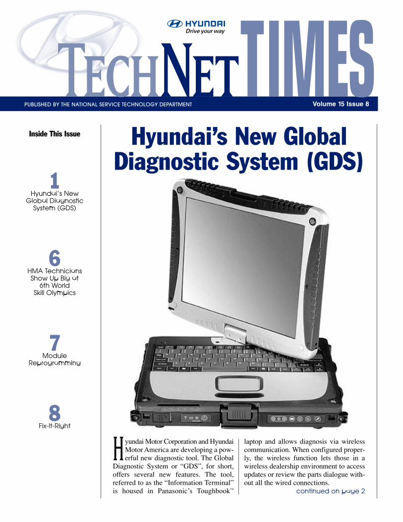
laptop and allows diagnosis via wirelesscommunication. When configured proper-ly, the wireless function lets those in awireless dealership environment to accessupdates or review the parts dialogue with-out all the wired connections.
Hyundai Motor Corporation and HyundaiMotor America are developing a pow-erful new diagnostic tool. The Global
Diagnostic System or “GDS”, for short,offers several new features. The tool,referred to as the “Information Terminal”is housed in Panasonic’s Toughbook™
Hyundai’s New GlobalDiagnostic System (GDS)
TechNetTIMESPUBLISHED BY THE NATIONAL SERVICE TECHNOLOGY DEPARTMENT Volume 15 Issue 8
2 TechNet Times
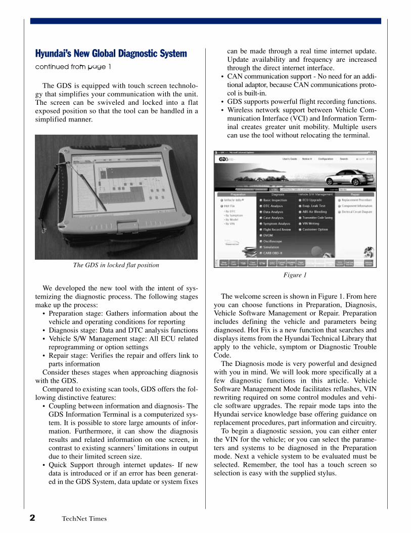
The GDS is equipped with touch screen technolo-gy that simplifies your communication with the unit.The screen can be swiveled and locked into a flatexposed position so that the tool can be handled in asimplified manner.
We developed the new tool with the intent of sys-temizing the diagnostic process. The following stagesmake up the process:
• Preparation stage: Gathers information about thevehicle and operating conditions for reporting
• Diagnosis stage: Data and DTC analysis functions • Vehicle S/W Management stage: All ECU related
reprogramming or option settings • Repair stage: Verifies the repair and offers link to
parts information Consider theses stages when approaching diagnosis
with the GDS.Compared to existing scan tools, GDS offers the fol-
lowing distinctive features:• Coupling between information and diagnosis- The
GDS Information Terminal is a computerized sys-tem. It is possible to store large amounts of infor-mation. Furthermore, it can show the diagnosisresults and related information on one screen, incontrast to existing scanners’ limitations in outputdue to their limited screen size.
• Quick Support through internet updates- If newdata is introduced or if an error has been generat-ed in the GDS System, data update or system fixes
can be made through a real time internet update.Update availability and frequency are increasedthrough the direct internet interface.
• CAN communication support - No need for an addi-tional adaptor, because CAN communications proto-col is built-in.
• GDS supports powerful flight recording functions.• Wireless network support between Vehicle Com-
munication Interface (VCI) and Information Term-inal creates greater unit mobility. Multiple userscan use the tool without relocating the terminal.
The welcome screen is shown in Figure 1. From hereyou can choose functions in Preparation, Diagnosis,Vehicle Software Management or Repair. Preparationincludes defining the vehicle and parameters beingdiagnosed. Hot Fix is a new function that searches anddisplays items from the Hyundai Technical Library thatapply to the vehicle, symptom or Diagnostic TroubleCode.
The Diagnosis mode is very powerful and designedwith you in mind. We will look more specifically at afew diagnostic functions in this article. VehicleSoftware Management Mode facilitates reflashes, VINrewriting required on some control modules and vehi-cle software upgrades. The repair mode taps into theHyundai service knowledge base offering guidance onreplacement procedures, part information and circuitry.
To begin a diagnostic session, you can either enterthe VIN for the vehicle; or you can select the parame-ters and systems to be diagnosed in the Preparationmode. Next a vehicle system to be evaluated must beselected. Remember, the tool has a touch screen soselection is easy with the supplied stylus.
Figure 1
The GDS in locked flat position
Hyundai’s New Global Diagnostic Systemcontinued from page 1
TechNet Times 3
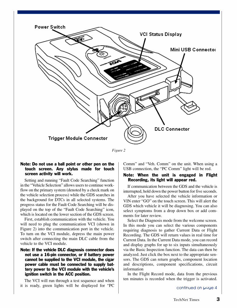
Figure 2
Note: Do not use a ball point or other pen on thetouch screen. Any stylus made for touchscreen activity will work.Setting and running “Fault Code Searching” function
in the “Vehicle Selection” allows users to continue work-flow on the primary system (denoted by a check mark onthe vehicle selection process) while the GDS searches inthe background for DTCs in all selected systems. Theprogress status for the Fault Code Searching will be dis-played on the top of the “Fault Code Searching” icon,which is located on the lower section of the GDS screen.
First, establish communication with the vehicle. Youwill need to plug the communication VCI (shown inFigure 2) into the communication port in the vehicle.To turn on the VCI module, depress the main powerswitch after connecting the main DLC cable from thevehicle to the VCI module.
Note: If the vehicle DLC diagnosis connector doesnot use a 16-pin connector, or if battery powercannot be supplied to the VCI module, the cigarpower cable must be connected to supply bat-tery power to the VCI module with the vehicle’signition switch in the ACC position.The VCI will run through a test sequence and when
it is ready, green lights will be displayed for “PC
Comm” and “Veh. Comm” on the unit. When using aUSB connection, the “PC Comm” light will be red.
Note: When the unit is engaged in FlightRecording, its light will appear red.If communication between the GDS and the vehicle is
interrupted, hold down the power button for five seconds. After you have selected the vehicle information or
VIN enter “GO” on the touch screen. This will alert theGDS which vehicle it will be diagnosing. You can alsoselect symptoms from a drop down box or add com-ments for later review.
Select the Diagnosis mode from the welcome screen.In this mode you can select the various componentsrequiring diagnosis to gather Current Data or FlightRecording. The GDS will return values in real time forCurrent Data. In the Current Data mode, you can recordand display graphs for up to six inputs simultaneouslyvia the Basic Inspection function. The data can then beanalyzed. Just click the box next to the appropriate sen-sors. The GDS can return graphs, component locationand descriptions, component specifications, circuitinformation
In the Flight Record mode, data from the previousten minutes is recorded when the trigger is activated.
continued on page 4
4 TechNet Times
This becomes helpful for intermittent problems. A con-dition experienced can be recorded after the fact if youare still within the ten-minute timeframe.
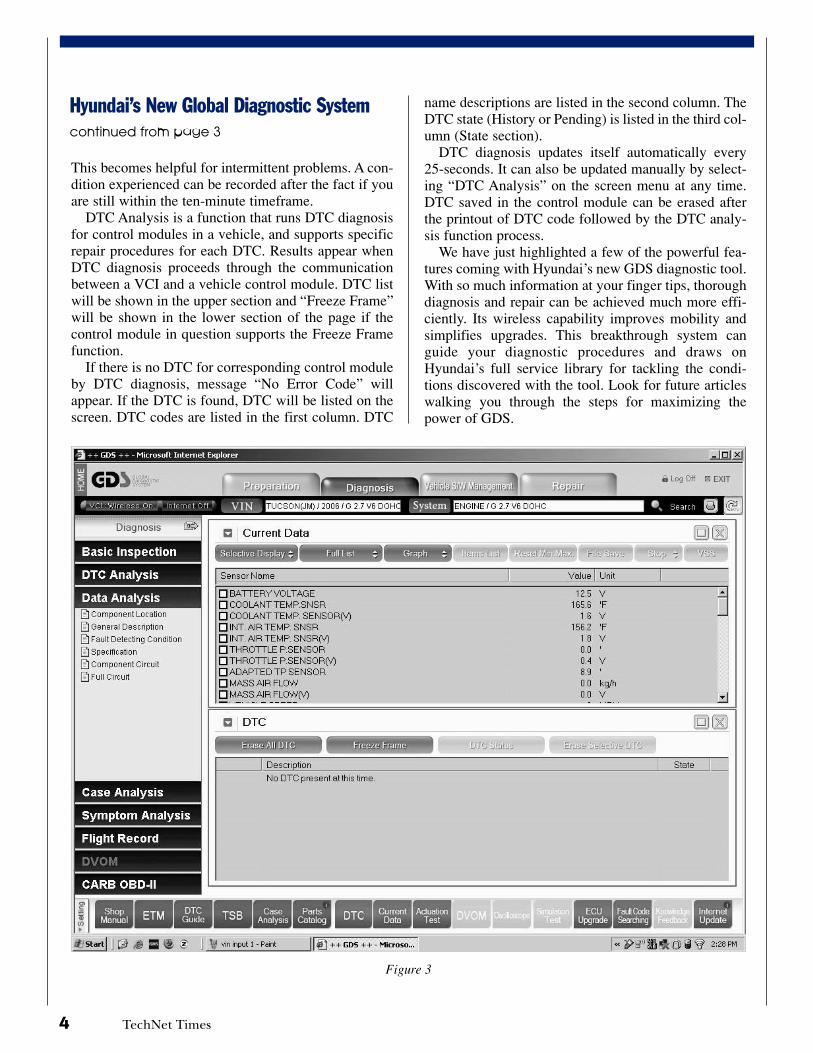
DTC Analysis is a function that runs DTC diagnosisfor control modules in a vehicle, and supports specificrepair procedures for each DTC. Results appear whenDTC diagnosis proceeds through the communicationbetween a VCI and a vehicle control module. DTC listwill be shown in the upper section and “Freeze Frame”will be shown in the lower section of the page if thecontrol module in question supports the Freeze Framefunction.
If there is no DTC for corresponding control moduleby DTC diagnosis, message “No Error Code” willappear. If the DTC is found, DTC will be listed on thescreen. DTC codes are listed in the first column. DTC
Hyundai’s New Global Diagnostic Systemcontinued from page 3
name descriptions are listed in the second column. TheDTC state (History or Pending) is listed in the third col-umn (State section).
DTC diagnosis updates itself automatically every25-seconds. It can also be updated manually by select-ing “DTC Analysis” on the screen menu at any time.DTC saved in the control module can be erased afterthe printout of DTC code followed by the DTC analy-sis function process.
We have just highlighted a few of the powerful fea-tures coming with Hyundai’s new GDS diagnostic tool.With so much information at your finger tips, thoroughdiagnosis and repair can be achieved much more effi-ciently. Its wireless capability improves mobility andsimplifies upgrades. This breakthrough system canguide your diagnostic procedures and draws onHyundai’s full service library for tackling the condi-tions discovered with the tool. Look for future articleswalking you through the steps for maximizing thepower of GDS.
Figure 3
TechNet Times 5
2
1
1
1
1
1
1
1
1
1
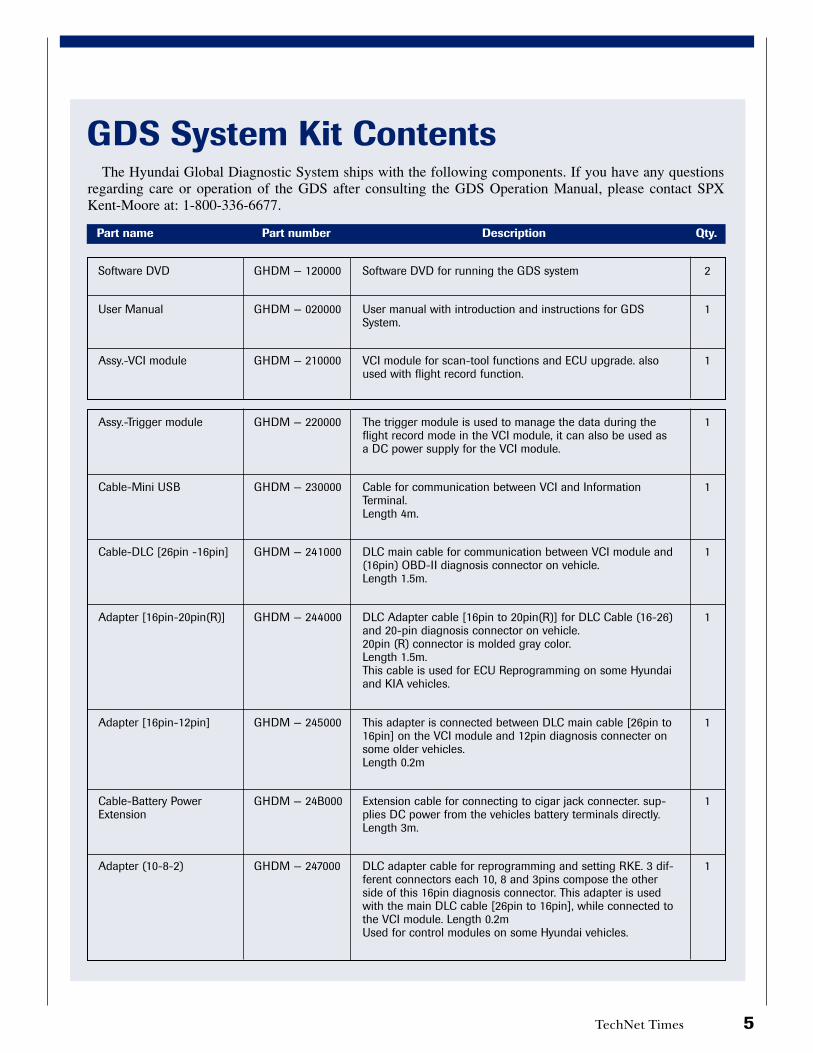
Software DVD
User Manual
Assy.-VCI module
Assy.-Trigger module
Cable-Mini USB
Cable-DLC [26pin -16pin]
Adapter [16pin-20pin(R)]
Adapter [16pin-12pin]
Cable-Battery PowerExtension
Adapter (10-8-2)
GHDM — 120000
GHDM — 020000
GHDM — 210000
GHDM — 220000
GHDM — 230000
GHDM — 241000
GHDM — 244000
GHDM — 245000
GHDM — 24B000
GHDM — 247000
Software DVD for running the GDS system
User manual with introduction and instructions for GDSSystem.
VCI module for scan-tool functions and ECU upgrade. alsoused with flight record function.
The trigger module is used to manage the data during theflight record mode in the VCI module, it can also be used asa DC power supply for the VCI module.
Cable for communication between VCI and InformationTerminal. Length 4m.
DLC main cable for communication between VCI module and(16pin) OBD-II diagnosis connector on vehicle. Length 1.5m.
DLC Adapter cable [16pin to 20pin(R)] for DLC Cable (16-26)and 20-pin diagnosis connector on vehicle. 20pin (R) connector is molded gray color. Length 1.5m. This cable is used for ECU Reprogramming on some Hyundaiand KIA vehicles.
This adapter is connected between DLC main cable [26pin to16pin] on the VCI module and 12pin diagnosis connecter onsome older vehicles. Length 0.2m
Extension cable for connecting to cigar jack connecter. sup-plies DC power from the vehicles battery terminals directly. Length 3m.
DLC adapter cable for reprogramming and setting RKE. 3 dif-ferent connectors each 10, 8 and 3pins compose the otherside of this 16pin diagnosis connector. This adapter is usedwith the main DLC cable [26pin to 16pin], while connected tothe VCI module. Length 0.2m Used for control modules on some Hyundai vehicles.
Part name Part number Description Qty.
GDS System Kit Contents The Hyundai Global Diagnostic System ships with the following components. If you have any questions
regarding care or operation of the GDS after consulting the GDS Operation Manual, please contact SPXKent-Moore at: 1-800-336-6677.
6 TechNet Times
Bow do you prepare to take on the world in showingyour automotive technical expertise? This year’steam from Hyundai Motor America showed that
they have the answers. Team members earned onegold, one silver and one bronze medal from the com-petition; and the fourth member received an Excellentrating. Prior to the Sixth World Skill Olympics held inKorea, HMA representatives at previously enduredthrough a rigorous selection process in September. Thequalification event, The National TroubleshootingContest dubbed “The Shootout” was based on thePlatinum Skills Challenge and Advanced DiagnosticsCourses. The Shootout format resembled challengesthat would be faced in Korea. With this year’s success,that preparation appears to have paid off. No one sentmore guys to the podium than the Team USA!
Frank Sura from Van Horn Hyundai of Fond DuLac, Wisconsin was awarded the Gold Medal in BodyElectrical. Frank sailed through the Body Electricaltask so easily that he spent most of the task time fin-ished, sitting in a new Accent waiting for the othersto complete the job.
In the Engine Systems category, Anthony Dehn
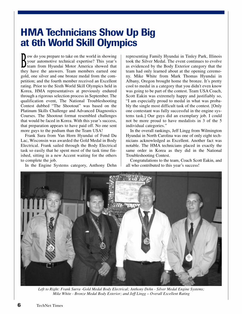
Left to Right: Frank Surra -Gold Medal Body Electrical; Anthony Dehn - Silver Medal Engine Systems;Mike White - Bronze Medal Body Exterior; and Jeff Lingg – Overall Excellent Rating
representing Family Hyundai in Tinley Park, Illinoistook the Silver Medal. The event continues to evolveas evidenced by the Body Exterior category that theteam had only learned about at the opening ceremo-ny. Mike White from Mark Thomas Hyundai inAlbany, Oregon brought home the bronze. It’s prettycool to medal in a category that you didn't even knowwas going to be part of the contest. Team USA Coach,Scott Eakin was extremely happy and justifiably so,“I am especially proud to medal in what was proba-bly the single most difficult task of the contest. [Onlyone contestant was fully successful in the engine sys-tems task.] Our guys did an exemplary job. I couldnot be more proud to have medalists in 3 of the 5individual categories.”
In the overall rankings, Jeff Lingg from WilmingtonHyundai in North Carolina was one of only eight tech-nicians acknowledged as Excellent. Another fact wasnotable. The HMA technicians placed in exactly thesame order in Korea as they did in the NationalTroubleshooting Contest.
Congratulations to the team, Coach Scott Eakin, andall who contributed to this year’s success!
HMA Technicians Show Up Bigat 6th World Skill Olympics
TechNet Times 7
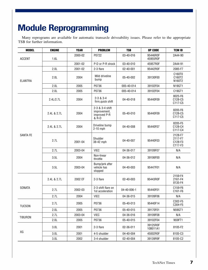
Module Reprogramming
MODEL
ACCENT
ELANTRA
SANTA FE
SONATA
TUCSON
TIBURON
XG
ENGINE
1.6L
2.0L
2.0L
2.0L
2.0L
2.4L/2.7L
2.4L & 2.7L
2.4L & 2.7L
2.7L
2.7L
3.5L
3.5L
2.4L & 2.7L
2.7L
2.7L
2.7L
2.0L
2.7L
2.0L
3.0L
3.0L
3.0L
YEAR
2000-02
2001-02
2001-02
2004
2005
2005
2004
2004
2004
2001-04
2003-04
2004
2003-04
2002 EF
2002-03
2004
2005
2005
2003-04
2005
2001
2001
2002
PROBLEM
P0722
P-D or P-R shock
2-3 flare
Mild drivelinebump
P0736
P0736
2-3 & 3-4firm,quick shift
2-3 & 3-4 shiftimprovement,improved P-R& R-D
Driveline bump2-10 mph
Shudder38-42 mph
VIEC
Non-linearthrottle
Bump/jerk aftervehicle hasstopped
2-3 flare
2-3 shift flare on1st acceleration
VIEC
P0736
P0736
VIEC
P0736
2-3 flare
4-5 shudder
3-4 shudder
TSB
03-40-016
03-40-010
02-40-001
05-40-002
005-40-014
005-40-014
04-40-018
05-40-010
04-40-008
04-40-007
04-36-017
04-36-012
04-40-003
02-40-003
04-40-006-1
04-36-015
05-40-013
05-40-015
04-36-016
05-40-015
02-36-011
04-40-004
02-40-004
OP CODE
95446R0F45955R0F
45957R0F
95442R0F
39130F00
39102F04
39102F04
95440F09
95440F09
95440F07
95440F03
39109F07
39106F00
95447F01
95443R0F
95440F01
39109F06
95440F14
39170F01
39109F08
39102F04
39125R0F10B011A1
45002R0F
39139R9F
TCM ID
2A44-90
2A44-91
2085-F7
C160T0C160T2N160T2
N19GT1
C19GT1
8025-F6C128-C5C117-C5
8205-F6C128-C5C117-C5
8205-F5C128-C4C117-C4
2128-F72117-F7C128-F3C117-F3
N/A
N/A
N/A
2159-F42161-F48135-F4
C159-F6C161-F6
N/A
C302-F5C304-F5
N59GT1
N/A
N59FT1
8105-F2
8105-C3
8105-C2
Many reprograms are available for automatic transaxle driveability issues. Please refer to the appropriateTSB for further information.

8 TechNet Times
Fix-It-RightAUTOMATIC TRANSAXLE - NO MOVEMENT IN DRIVE OR REVERSE GEARMODEL: ALL
DESCRIPTION:If you are servicing a vehicle with no movement in
drive or reverse gear, follow the procedure shownbelow:
REPAIR PROCEDURE:
1. Check for DTC in both the “Engine” and“Automatic Transaxle” menus:
• If DTC are found, refer to TSB 05-40-008 or 04-40-020 for repair guidance.
• If no DTC are found, go to Step 2.
2. Remove the dipstick and check the ATF for astrong burnt smell. If the smell does not provideconclusive results, remove the oil pan and checkfor metal particles in the pan:
• If a strong burnt smell or metal particles arefound, replace the transaxle
• If not, go to Step 3
NOTE: ATF that is a dark brown or black colordoes not indicate an internal transaxle concern;do not replace the transaxle. SPIII may changecolor to a dark brown after 10,000 to 25,000miles in service. This change is normal for thistype of ATF.
VERIFY THE RANGE SWITCH ADJUSTMENT:
3. Move the shift lever to “N”.
4. Insert a 5 mm drill or M5 (5 mm) bolt in theadjustment hole of the range switch. Check that thedrill or bolt fits into the adjustment holes.
• If not, go to Step 5
• If so, go to Step 9
5. Loosen the two 10 mm mounting bolts.
6. Disconnect the shift cable at the lever.
7. Insert a 5 mm drill or M5 (5 mm) bolt in theadjustment hole of the range switch. Tighten thetwo 10 mm mounting bolts to specification.
Specification: 7-8 ft.lb (10-12 Nm, 100-120 kg.cm)
Insert M5 bolt
Tighten bolts Insert M5 bolt
3
4
5
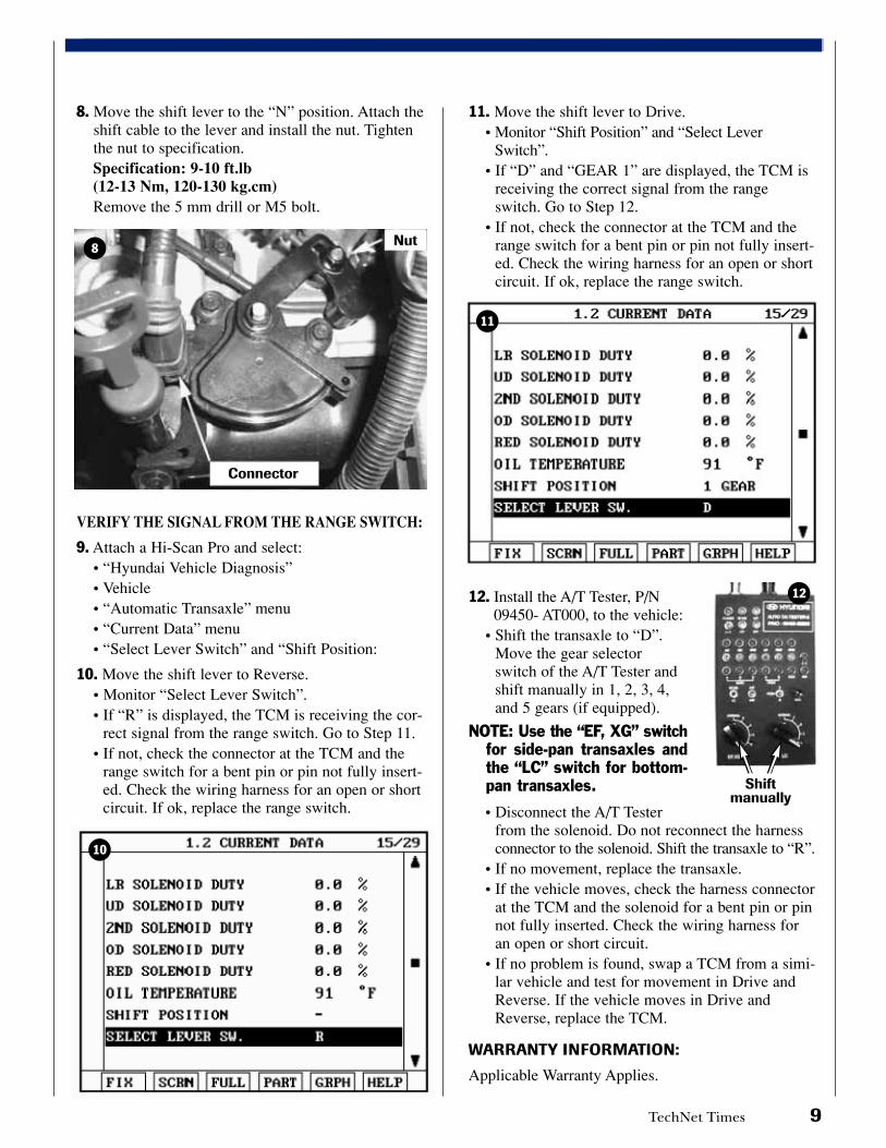
8. Move the shift lever to the “N” position. Attach theshift cable to the lever and install the nut. Tightenthe nut to specification.Specification: 9-10 ft.lb (12-13 Nm, 120-130 kg.cm)Remove the 5 mm drill or M5 bolt.
VERIFY THE SIGNAL FROM THE RANGE SWITCH:
9. Attach a Hi-Scan Pro and select:• “Hyundai Vehicle Diagnosis”• Vehicle• “Automatic Transaxle” menu• “Current Data” menu• “Select Lever Switch” and “Shift Position:
10. Move the shift lever to Reverse.• Monitor “Select Lever Switch”.• If “R” is displayed, the TCM is receiving the cor-
rect signal from the range switch. Go to Step 11.• If not, check the connector at the TCM and the
range switch for a bent pin or pin not fully insert-ed. Check the wiring harness for an open or shortcircuit. If ok, replace the range switch.
11. Move the shift lever to Drive.• Monitor “Shift Position” and “Select Lever
Switch”.• If “D” and “GEAR 1” are displayed, the TCM is
receiving the correct signal from the rangeswitch. Go to Step 12.
• If not, check the connector at the TCM and therange switch for a bent pin or pin not fully insert-ed. Check the wiring harness for an open or shortcircuit. If ok, replace the range switch.
12. Install the A/T Tester, P/N09450- AT000, to the vehicle:
• Shift the transaxle to “D”.Move the gear selectorswitch of the A/T Tester andshift manually in 1, 2, 3, 4,and 5 gears (if equipped).
NOTE: Use the “EF, XG” switchfor side-pan transaxles andthe “LC” switch for bottom-pan transaxles.
• Disconnect the A/T Testerfrom the solenoid. Do not reconnect the harnessconnector to the solenoid. Shift the transaxle to “R”.
• If no movement, replace the transaxle.• If the vehicle moves, check the harness connector
at the TCM and the solenoid for a bent pin or pinnot fully inserted. Check the wiring harness foran open or short circuit.
• If no problem is found, swap a TCM from a simi-lar vehicle and test for movement in Drive andReverse. If the vehicle moves in Drive andReverse, replace the TCM.
WARRANTY INFORMATION:
Applicable Warranty Applies.
TechNet Times 9
Connector
Nut
Shiftmanually
8
10
11
12
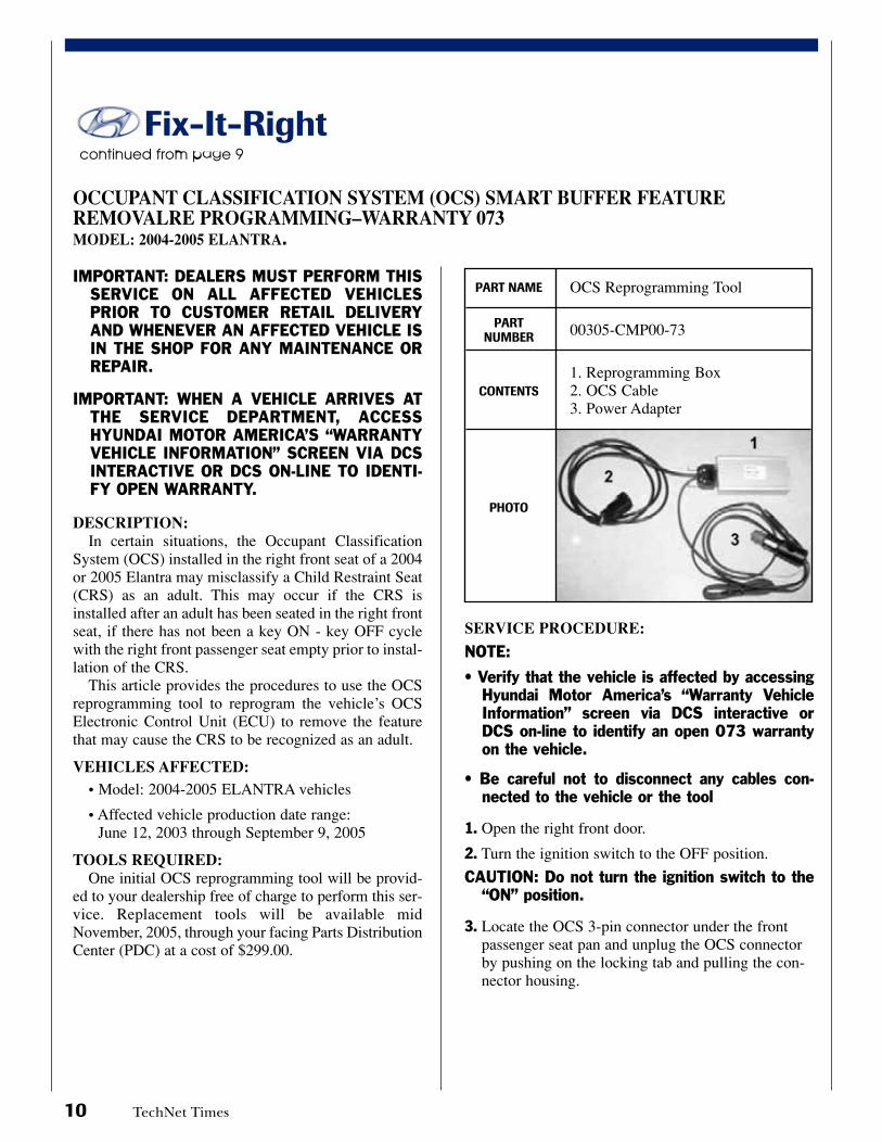
OCS Reprogramming Tool
00305-CMP00-73
1. Reprogramming Box2. OCS Cable3. Power Adapter
10 TechNet Times
IMPORTANT: DEALERS MUST PERFORM THISSERVICE ON ALL AFFECTED VEHICLESPRIOR TO CUSTOMER RETAIL DELIVERYAND WHENEVER AN AFFECTED VEHICLE ISIN THE SHOP FOR ANY MAINTENANCE ORREPAIR.
IMPORTANT: WHEN A VEHICLE ARRIVES ATTHE SERVICE DEPARTMENT, ACCESSHYUNDAI MOTOR AMERICA’S “WARRANTYVEHICLE INFORMATION” SCREEN VIA DCSINTERACTIVE OR DCS ON-LINE TO IDENTI-FY OPEN WARRANTY.
DESCRIPTION:In certain situations, the Occupant Classification
System (OCS) installed in the right front seat of a 2004or 2005 Elantra may misclassify a Child Restraint Seat(CRS) as an adult. This may occur if the CRS isinstalled after an adult has been seated in the right frontseat, if there has not been a key ON - key OFF cyclewith the right front passenger seat empty prior to instal-lation of the CRS.
This article provides the procedures to use the OCSreprogramming tool to reprogram the vehicle’s OCSElectronic Control Unit (ECU) to remove the featurethat may cause the CRS to be recognized as an adult.
VEHICLES AFFECTED:• Model: 2004-2005 ELANTRA vehicles
• Affected vehicle production date range: June 12, 2003 through September 9, 2005
TOOLS REQUIRED:One initial OCS reprogramming tool will be provid-
ed to your dealership free of charge to perform this ser-vice. Replacement tools will be available midNovember, 2005, through your facing Parts DistributionCenter (PDC) at a cost of $299.00.
SERVICE PROCEDURE:
NOTE:
• Verify that the vehicle is affected by accessingHyundai Motor America’s “Warranty VehicleInformation” screen via DCS interactive orDCS on-line to identify an open 073 warrantyon the vehicle.
• Be careful not to disconnect any cables con-nected to the vehicle or the tool
1. Open the right front door.
2. Turn the ignition switch to the OFF position.
CAUTION: Do not turn the ignition switch to the“ON” position.
3. Locate the OCS 3-pin connector under the frontpassenger seat pan and unplug the OCS connectorby pushing on the locking tab and pulling the con-nector housing.
PART NAME
PART NUMBER
CONTENTS
PHOTO
OCCUPANT CLASSIFICATION SYSTEM (OCS) SMART BUFFER FEATUREREMOVALRE PROGRAMMING–WARRANTY 073MODEL: 2004-2005 ELANTRA.
continued from page 9
Fix-It-Right
TechNet Times 11
continued on page 12
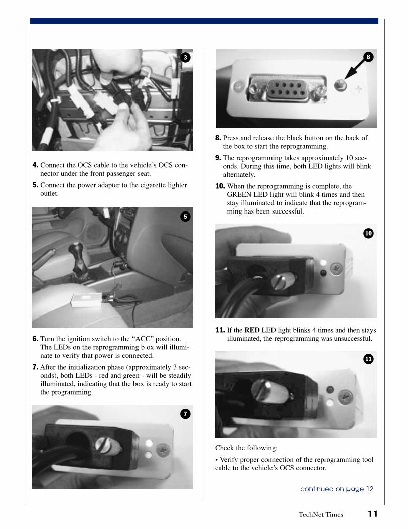
4. Connect the OCS cable to the vehicle’s OCS con-nector under the front passenger seat.
5. Connect the power adapter to the cigarette lighteroutlet.
6. Turn the ignition switch to the “ACC” position.The LEDs on the reprogramming b ox will illumi-nate to verify that power is connected.
7. After the initialization phase (approximately 3 sec-onds), both LEDs - red and green - will be steadilyilluminated, indicating that the box is ready to startthe programming.
8. Press and release the black button on the back ofthe box to start the reprogramming.
9. The reprogramming takes approximately 10 sec-onds. During this time, both LED lights will blinkalternately.
10. When the reprogramming is complete, theGREEN LED light will blink 4 times and thenstay illuminated to indicate that the reprogram-ming has been successful.
11. If the RED LED light blinks 4 times and then staysilluminated, the reprogramming was unsuccessful.
Check the following:
• Verify proper connection of the reprogramming toolcable to the vehicle’s OCS connector.
3 8
10
11
5
7
TechNet TimesVolume 15 Issue 8 November 2005TechNet Times is published monthly by HyundaiMotor America’s National Service TechnologyDepartment for Hyundai Dealership Technicians.The subjects covered in this publication are oftenone of a kind items, but they may help you to solvesimilar incidents. In all cases, the diagnosticprocedures recommended in the Shop Manualsshould always be performed first.
Please address all correspondence to:
Editor–TechNet TimesNational Service Technology Department
Hyundai Motor AmericaP.O. Box 20850
10550 Talbert AvenueFountain Valley, CA 92728-0850
© 2005 Hyundai Motor America
TechNet TriviaTrivia Question: Which came first, the FAX machine or the
automobile?
Last issue’s Trivia Answer: The correct chronological order is —First U.S. Toll Road: 1792, First Spark Plug: 1860;FIrst Auto Insurance Policy: 1897, World War I:1914-1918, First Powered Windshield Wipers: 1923.
• The power supply (voltage) at the cigarette lighteroutlet may be too low.
Check the two conditions above. Disconnect thepower adapter from the cigarette lighter outlet andreconnect to reset the reprogramming tool. Start thereprogramming procedure again. Go to Step #6 aftersuccessful programming.
12. Turn the ignition to the OFF position.
13. Disconnect the reprogramming tool.
continued from page 11
Fix-It-Right
14. Reconnect the OCS connector under the rightfront passenger seat.
15. Check for diagnostic codes (DTC) using the Hi-Scan Pro. Erase all trouble codes.
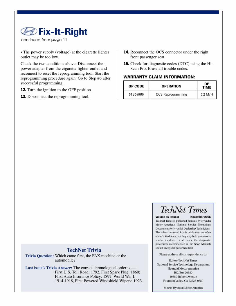
WARRANTY CLAIM INFORMATION:
OP CODE OPERATION OP
TIME
51B040R0 OCS Reprogramming 0.2 M/H
Related Documents