Issue-1.01 June, 2000 NEW HYBRID TELEPHONE SYSTEM GROUPHONE INSTRUCTION AND INSTALLATION MANUAL 2 2 2

Welcome message from author
This document is posted to help you gain knowledge. Please leave a comment to let me know what you think about it! Share it to your friends and learn new things together.
Transcript

Issue-1.01
June, 2000
NEW HYBRID TELEPHONE SYSTEM
GROUPHONE
INSTRUCTIONAND
INSTALLATION MANUAL
2222

Nothing contained in this manual shall be deemed to be, and this manual does not constitute,a warranty of, or representation with respect to, any of the equipment covered. This manual issubject to change without notice and Nitsuko has no obligation to provide any updates orcorrections to this manual. Further, Nitsuko also reserves the right, without prior notice, tomake changes in equipment design or components as it deems appropriate. Norepresentation is made that this manual is complete or accurate in all respects and Nitsukoshall not be liable for any errors or omissions. In no event shall Nitsuko be liable for anyincidental or consequential damages in connection with the use of this manual. No part of thisdocument may be photocopied or reproduced without prior written consent of Nitsuko.
(C) 2000 by Nitsuko Corporation. All Rights Reserved.
Printed in Japan

This manual consists of six parts:
PART 1: SPECIFICATIONS
PART 2: SYSTEM INSTALLATION
PART 3: FEATURE DESCRIPTION AND OPERATION
PART 4: SYSTEM PROGRAMMING
PART 5: OPTIONAL ITEMS
PART 5-1: Caller-ID Unit
PART 5-2: Voice Announce Unit
PART 5-3: System Up Grade (ROMU)

PART 1
SPECIFICATIONS
General Description
System Configuration
System Construction

1-1
System Capacity
Items TX-Z2 824 System
System Size 408 616 824
Trunk Line 4 6 8
Extension(Max.) 8 16 24
Key Telephone 8 16 24
Single Line Telephone 8 16 24
DLS Console Max. 3 (Use DLS console as DSS console.)
Intercom Talk Path 5
Paging Path 1
DTMF Receiver 3 6 9
Doorphone Interface 2
BGM / External MOH Input 1(Common)
External Speaker Output 1
Ringer Included with 408M Main Unit
Power Failure Transfer Line 1 2 3
Electrical Specifications
Station Cable Length Limit
Key Telephone 300 m (0.5 φ two-pair twisted cable).
Single Line Telephone 1,125 m (0.5 φ one-pair twisted cable).
Doorphone Box 150 m (0.5 φ one-pair twisted cable).
* Off-premises extension is not allowed. In other words, do not run the wirein outdoor.
Power Supplies
Primary Power 110 – 240 V AC, 50/60 Hz (1.4 – 0.8A)
Power Consumption 70 Watts maximum.
Secondary Power +5 V DC, +12 V DC, +28 V DC.
Part 1::::Specification
General Description
1-2
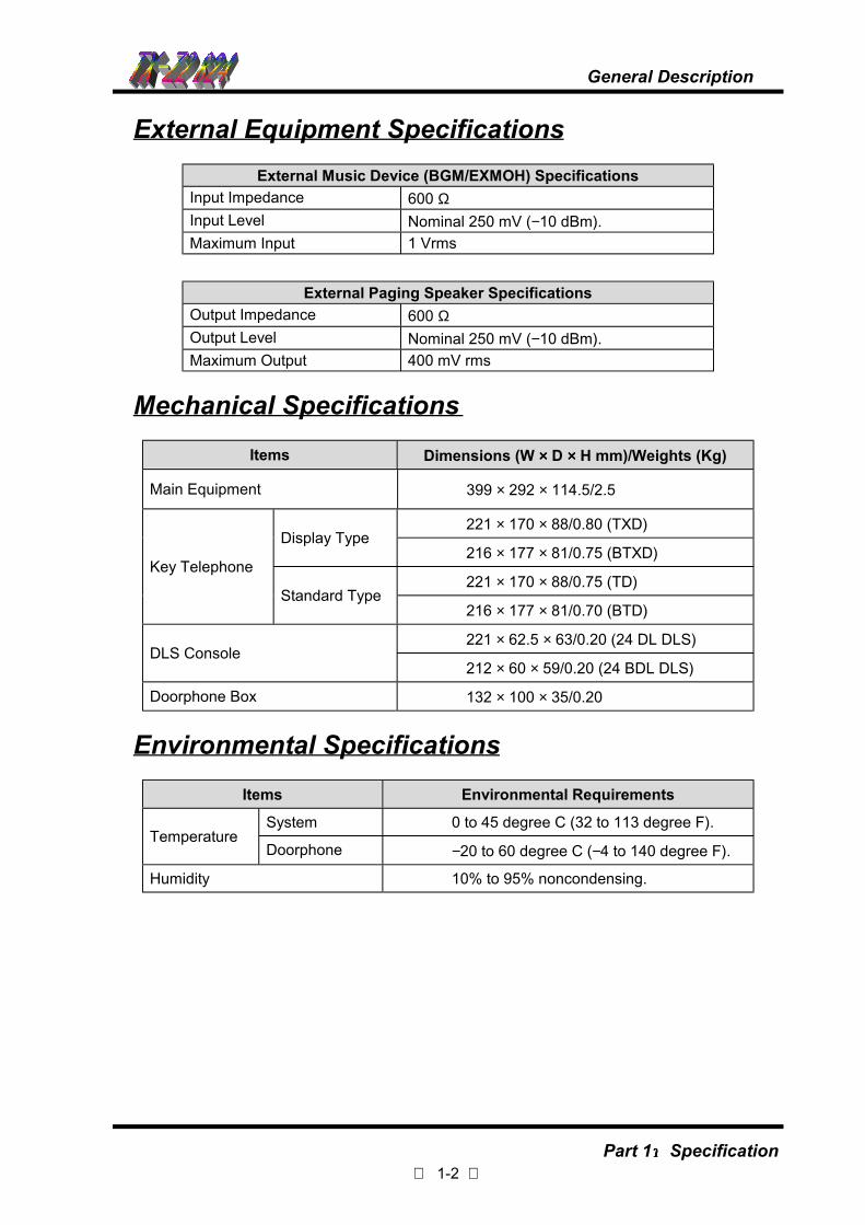
External Equipment Specifications
External Music Device (BGM/EXMOH) Specifications
Input Impedance 600 ΩInput Level Nominal 250 mV (−10 dBm).
Maximum Input 1 Vrms
External Paging Speaker Specifications
Output Impedance 600 ΩOutput Level Nominal 250 mV (−10 dBm).
Maximum Output 400 mV rms
Mechanical Specifications
Items Dimensions (W ×××× D ×××× H mm)/Weights (Kg)
Main Equipment 399 × 292 × 114.5/2.5
221 × 170 × 88/0.80 (TXD)Display Type
216 × 177 × 81/0.75 (BTXD)
221 × 170 × 88/0.75 (TD)Key Telephone
Standard Type216 × 177 × 81/0.70 (BTD)
221 × 62.5 × 63/0.20 (24 DL DLS)DLS Console
212 × 60 × 59/0.20 (24 BDL DLS)
Doorphone Box 132 × 100 × 35/0.20
Environmental Specifications
Items Environmental Requirements
System 0 to 45 degree C (32 to 113 degree F).Temperature
Doorphone −20 to 60 degree C (−4 to 140 degree F).
Humidity 10% to 95% noncondensing.
General Description
Part 1::::Specification

1-3
System Configuration
Name DescriptionQuantity/System
Remarks
NX8E-824M. ME TX-Z2 824 Main Equipment 1
CPU, Power Supply, batterycharger, Ringer for SLT, 4-Trunk/8-extension interface,1 power failure transfercircuit for SLT,EXMOH/BGM input andSMDR or Local remoteprogramming interfaceincluded.
NX.E-6TD TXZ KTS6 Line keys, standard type KeyTelephone
NX.E-6TXD TXZ KTS 6 Line keys, display type Key Telephone
NX.E-12TD TXZ KTS12 Line keys, standard type KeyTelephone
NX.E-12TXD TXZ KTS12 Line keys, display type KeyTelephone
1st Model(Productiondiscontinue).
Modular station cableincluded.
NX.E-6BTD TXZ KTS6 Line keys, standard type KeyTelephone
NX.E-6BTXD TXZ KTS 6 Line keys, display type Key Telephone
NX.E-12BTD TXZ KTS12 Line keys, standard type KeyTelephone
NX.E-12BTXD TXZ KTS12 Line keys, display type KeyTelephone
24
2nd Model.Modular station cableincluded.
NX8E-208E-M1 2-Trunk/8-extension cardWith 1 power failure transfercircuit
NX8E-008E-M1 8-extension card2
NX8E-DHU-M12-Doorphone I/F, 2-relay contacts,External Paging output
1
NX8E-VAU-M1 Voice Announce/ FAX transfer Card 1
NX8E-4CIDU-M1 Caller-ID interface Card (For 4 lines) 1 For mount to 408M unit
NX8E-2CIDU-M1 Caller-ID interface Card (For 2 lines) 2 For mount to 208E unit
NX8E-MODEMU-M1 Modem Card 1 *For Remote Programming
NX8E RemoteProgramming Software
Remote Programming Software 1
NX8E-ROMU-M1 Software Version Up 1 For version up the system
NX.E-24DL TXZ DLS24 key DLS Console for 1st Model KeyTelephone (used as DSS Console)
NX.E-24BDL TXZ DLS24 key DLS Console for 2nd Model KeyTelephone (used as DSS Console)
(1)3
Connected to display typekey telephone.
NX7-24BDL W.M.K Wall mount bracket for 24BDL DLSAs
needed
NT-S-D6 2-wire doorphone box 2 DHU-M1 is required.
Voice Mail I/F Voice Mail Interface UnitAs
neededRequired for VM connection
DX2E-32i/NX7EBATTERY BOX
External backup battery box 1NP2.6 or equivalentbatteries are required.
System Configuration
Part 1::::Specification

1-4
System Configuration (Cont’d)
Name DescriptionQuantity/System
Remarks
NX.E TXZ W.M.KWall-mount bracket (for 1st and 2ndmodel key telephones)
Asneeded
NX.E TXZABB. CARD SET
Pull-out type abbreviated dial numbercard (20 pcs)
Asneeded
DX.EABB. CARD SET
Stand type abbreviated dial number card(20 pcs)
Asneeded
1 pce. per Key telephone.
NOTE1: The above list shows composition of a system with full capacity.NOTE2: On-site Access is not required to install MODEM unit.
System Configuration
Part 1::::Specification
1-5
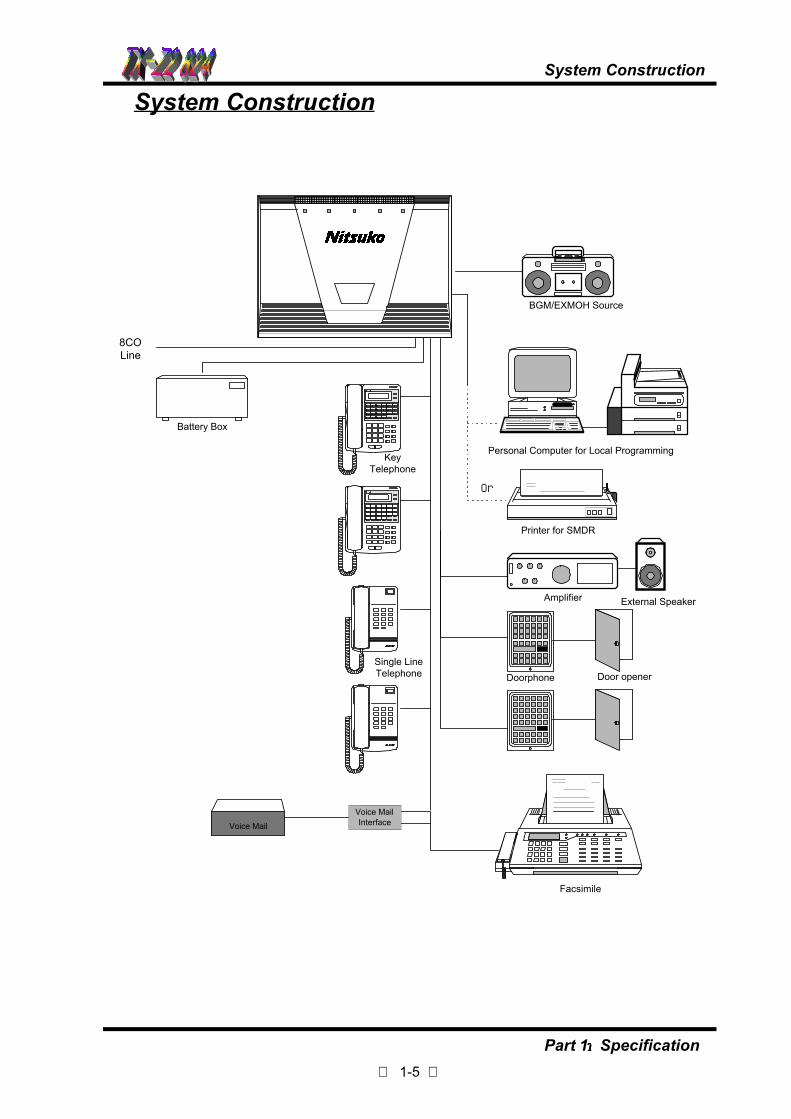
System Construction
System Construction
BGM/EXMOH Source
Personal Computer for Local Programming
Printer for SMDR
Amplifier External Speaker
Doorphone Door opener
8COLine
Battery Box
Voice MailInterfaceVoice Mail
KeyTelephone
Single LineTelephone
Facsimile
Or
Part 1::::Specification

PART 2
SYSTEM INSTALLATION
Precaution
Installation of TX-Z2 824 System

Table of Contents
Precaution ........................................................................................................ 2-1
Installing the Main Equipment.......................................................................... 2-3
The Card Locations.......................................................................................... 2-5
Grounding Requirements................................................................................. 2-5
Connector Assembly ........................................................................................ 2-6
Trunk Line Connection..................................................................................... 2-6
Extension Connection ...................................................................................... 2-7
Cable Routing and Cramping........................................................................... 2-8
Installing Expansion PCBs............................................................................... 2-8
Station Message Detail Recording .................................................................. 2-9
Connection for Serial Interface cable............................................................. 2-10
Installing External MOH and BGM................................................................. 2-11
Installing the DHU-M1 PCB ........................................................................... 2-12
Installing the Doorphone Box......................................................................... 2-13
Installing External Paging Output .................................................................. 2-14
Installing External Device Control .................................................................. 2-15
Lithium Battery Installation............................................................................. 2-15
Backup Battery Connection ........................................................................... 2-16
Power Failure Transfer .................................................................................. 2-17
Installing DLS Console................................................................................... 2-18

-2-1-
Precaution
Please read the following notes concerning installation and connection before installing the system.
! Never attempt to insert wires, pins, etc. into the vents or other holes of this unit.
! If there is any trouble, disconnect the unit from the telephone line. Plug the telephone directly to thetelephone line. If the telephone operates properly, do not reconnect the unit to the line until the troublehas been repaired. If the telephone does not operate properly, the chances are that the trouble is inthe telephone system, and not in the unit.
! Do not use benzine, thinner, or the like, or any abrasive powder to clean the cabinet. Wipe it with asoft cloth.
WARNING
WHEN A FAILURE OCCURS WHICH RESULTS IN THE INTERNAL PARTS BECOMINGACCESSIBLE, DISCONNECT THE POWER SUPPLY CORD IMMEDIATELY AND RETURNTHIS UNIT TO YOUR DEALER.
DISCONNECT THE TELECOM CONNECTION BEFORE DISCONNECTING THE POWERCONNECTION PRIOR TO RELOCATING THE EQUIPMENT, AND RECONNECT THEPOWER FIRST.
THIS UNIT IS EQUIPPED WITH AN EARTHING CONTACT PLUG FOR SAFETY REASONSTHIS PLUG MUST ONLY BE CONNECTED TO AN EARNING CONTACT SOCKET WHICHHAS BEEN INSTALLED ACCORDING TO REGULATIONS.
THE POWER SOCKET WALL OUTLET SHOULD BE LOCATED NEAR THIS EQUIPMENTAND BE EASILY ACCESSIBLE.
TO PREVENT FIRE OR SHOCK HAZARD, DO NOT EXPOSE THIS PRODUCT TO RAIN ORANY TYPE OF MOISTURE.
Make sure to keep the following instruction when exchange the Fuse.
! When you change the Fuses on the Power Supply, Disconnect the Power connection first and
exchange the Fuses.
Caution !! Double Pole/Neutral Fusing

-2-2-
Precaution
Safety Installation InstructionsWhen installing telephone wiring, basic safety precautions should always be followed to reduce the riskof fire, electric shock and injury to people, including the following:
1. Never install telephone wiring during a lightning storm.2. Never install telephone jacks in wet locations unless the jack is specifically designed for wet
locations.3. Never touch non-insulated telephone wires or terminals unless the telephone line has been
disconnected at the network interface.4. Use caution when installing or modifying telephone lines.
Installation PrecautionsThis set is exclusively made for wall mounting only. Avoid installing in the following places.(Doing so may result malfunction, noise or discoloration.)
1. In direct sunlight and hot, cold, or humid places. (Temperature range: 0°C-45°C/32°F- 113°F)2. Sulfuric gases produced in areas where there are thermal springs, etc., may damage the
equipment or contacts.3. Places in which shocks or vibrations are frequent or strong.4. Dusty places, or places where water or oil may come into contact with the unit.5. Near high-frequency generating devices such as sewing machines or electric welders.6. On or near computers telexes, or other office equipment, as well as microwave ovens or air
conditioners, (It is preferable not to install in the same room with the above equipment.)7. Install at least 1.8 m (6 feet) from radios and televisions. (both the main unit and a key telephone)8. Do not obstruct area around the main unit (for reasons of maintenance and inspection - be
especially careful to allow space for cooling above and at the sides of the main unit).
Wiring PrecautionsMake sure to keep the following instructions when wiring.
1. Do not wire the telephone cable in parallel with an AC power source, computer, telex, etc. If thecables are run near those wires, shield the cables with metal tubing or use shielded cables andground the shields.
2. If cables are run on the floor, use protectors or the like to protect the wires where they may bestepped on. Avoid wiring under carpets.
3. Avoid using the same power supply outlet for computers, telexes, and other office equipment.Otherwise, the TX-Z2 824's system operation may be interrupted by the induction noise from suchequipment.
4. Please use one pair telephone wire for extension connection of (telephone) equipment such asstandard telephones, answering machines, etc., except key telephones.
5. The AC cord must be plugged off during wiring. After all the wiring are completed, plug the ACcord into an AC outlet.
6. Wiring error may cause the system to operate improperly.7. If an extension does not operate properly, disconnect the telephone from the extension line and
then connect again, or plug off the AC cord of the system and then on again.8. Use twisted pair cable for Trunk line connection.9. Trunk Lines should be installed with lightning protectors.10. The aerial distribution wiring is not allowed.

-2-3-
Installing the Main Equipment (Wall Mounting)The Main Equipment should be installed in a clean, dry, centrally-located spot (such as a closet), where itis out of direct sunlight. The area should be free of moisture (water, dampness, etc.), and away from anyequipment which might vibrate. You should choose a location that is well-ventilated, where thetemperature does not exceed that of a normal room.
Step 1: Before wall mounting the TX-Z2 824 Main Equipment, the top cover of Main Equipment must beremoved. Loosen the two screws and remove the top cover as illustration.
Step 2: Tack-fasten two of the four wood screws (provided with Main Equipment) on the wall at about320 mm apart.
STEP 1 Top Cover
399
320
350
28.5
235
292

-2-4-
Installing the Main Equipment (Wall Mounting)Step 3: Place the two holes of the main unit over the tacked wood screws to hang the Main Equipment onthe wall and then fully tighten the wood screws.
Step 4: Fasten another two screws on the wall through the two bottom holes of the Main Equipment.
PRECAUTIONARY SAFEGUARDS
1. Never install the Main Equipment where it may be exposed to water (near a bathtub, pool, sink, etc.).2. Never mount the Main Equipment on an unstable surface, where it might fall.3. Never block the vents on the Main Equipment. These vents prevent the unit from overheating.
Proper ventilation must be supplied for the unit.4. Never place any objects inside the vents of the Main Equipment.
STEP 4STEP 3

-2-5-
The Card Locations
Grounding Requirement
" The Card Locations
The card locations for the Main Equipment are shown in the following illustration.
" Grounding Requirement
The main equipment must be properly grounded. If circuit ground is not available at the dedicated ACoutlet, the following steps should be taken:
Step1: Provide a suitable ground in accordance with the local operating telephone company procedures.
Step2: Where a ground is used, a grounding terminal is provided on the Main Equipment.
ROMUDHU MODEMU
ETH1 ETH2 CO4 CO3 CO2 CO1 TEL8 TEL7 TEL6 TEL5 TEL4 TEL3 TEL2 TEL1
Power Supply
NX8E-208E-M1/NX8E-008E-M1NX8E-208E-M1/NX8E-008E-M1
NX8E-2CIDU-M1NX8E-4CIDU-M1
NX8E-VAU-M1 NX8E-408M-M1
DC SW
AC SW
ETH
To ground
Caution!!Grounding connection is very importantto protect the system.
-2-6-
Connector Assembly
Trunk Line Connection
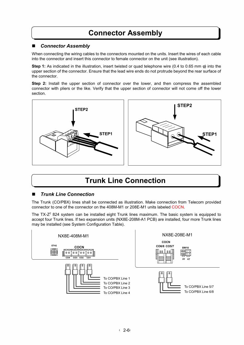
" Connector Assembly
When connecting the wiring cables to the connectors mounted on the units. Insert the wires of each cableinto the connector and insert this connector to female connector on the unit (see illustration).
Step 1: As indicated in the illustration, insert twisted or quad telephone wire (0.4 to 0.65 mm φ) into theupper section of the connector. Ensure that the lead wire ends do not protrude beyond the rear surface ofthe connector.
Step 2: Install the upper section of connector over the lower, and then compress the assembledconnector with pliers or the like. Verify that the upper section of connector will not come off the lowersection.
" Trunk Line Connection
The Trunk (CO/PBX) lines shall be connected as illustration. Make connection from Telecom providedconnector to one of the connector on the 408M-M1 or 208E-M1 units labeled COCN.
The TX-Z2 824 system can be installed eight Trunk lines maximum. The basic system is equipped toaccept four Trunk lines. If two expansion units (NX8E-208M-A1 PCB) are installed, four more Trunk linesmay be installed (see System Configuration Table).
STEP1
STEP2
ETH2
CO4 CO3 CO2 CO1
NX8E-408M-M1
To CO/PBX Line 1
To CO/PBX Line 2To CO/PBX Line 3
To CO/PBX Line 4
COCN
COCN
CO6/8 CO5/7
To CO/PBX Line 5/7
To CO/PBX Line 6/8
SW100
PF KT
NX8E-208E-M1
1 2 34 STEP1
STEP2
-2-7-
Extension Connection
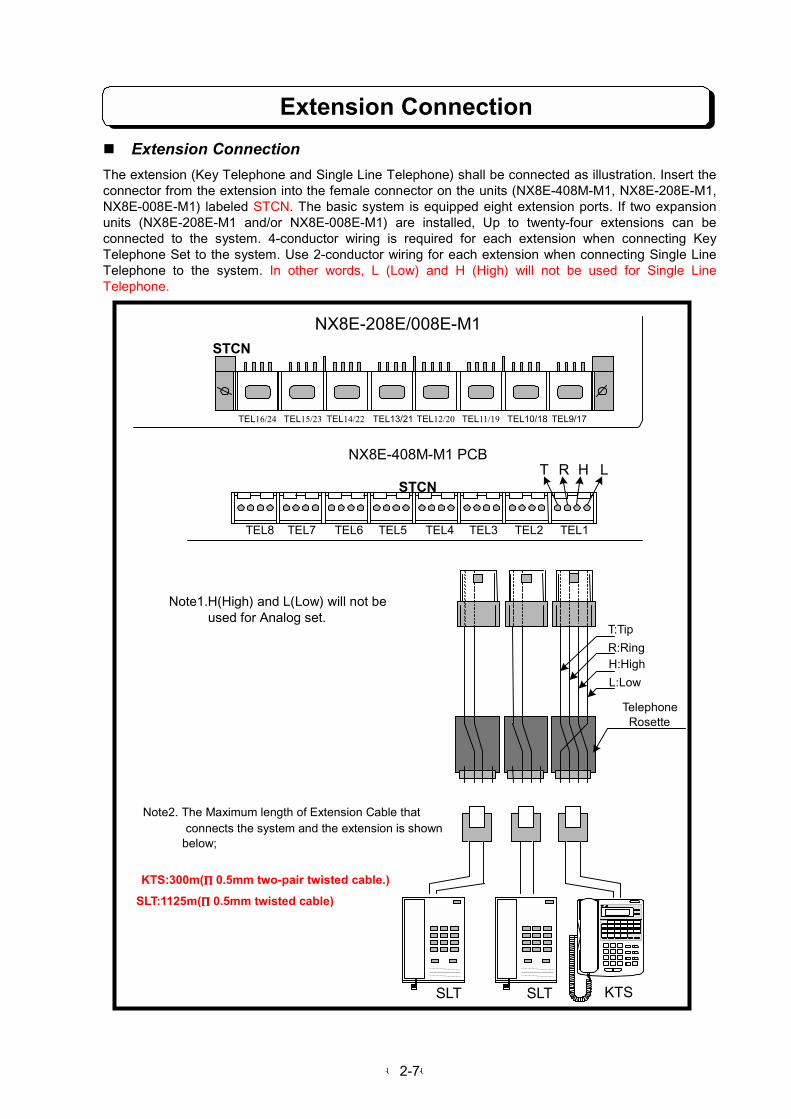
" Extension Connection
The extension (Key Telephone and Single Line Telephone) shall be connected as illustration. Insert theconnector from the extension into the female connector on the units (NX8E-408M-M1, NX8E-208E-M1,NX8E-008E-M1) labeled STCN. The basic system is equipped eight extension ports. If two expansionunits (NX8E-208E-M1 and/or NX8E-008E-M1) are installed, Up to twenty-four extensions can beconnected to the system. 4-conductor wiring is required for each extension when connecting KeyTelephone Set to the system. Use 2-conductor wiring for each extension when connecting Single LineTelephone to the system. In other words, L (Low) and H (High) will not be used for Single LineTelephone.
STCN
STCN
TEL8 TEL7 TEL6 TEL5 TEL4 TEL3 TEL2 TEL1
TEL16/24 TEL15/23 TEL14/22 TEL13/21 TEL12/20 TEL11/19 TEL10/18 TEL9/17
NX8E-208E/008E-M1
NX8E-408M-M1 PCBT R H L
TelephoneRosette
T:Tip
R:RingH:High
L:Low
Note1.H(High) and L(Low) will not be used for Analog set.
Note2. The Maximum length of Extension Cable that connects the system and the extension is shown
below;
KTS:300m(φφφφ0.5mm two-pair twisted cable.)
SLT:1125m(φφφφ0.5mm twisted cable)
KTSSLTSLT

-2-8-
Cable Routing and Cramping
Installing Expansion PCBs
" Cable Routing and Cramping
All cabling should exit from the right side ofthe Main Equipment. Route and cramp thecable for the Main Equipment as illustratedon the right side.
" Installing Expansion PCBs
The NX8E-208E-M1 PCB is CO/PBX and station interface card which provides two CO/PBX interface,eight station interface. The NX8E-008E-M1 PCB is station interface card which provides eight stationinterface. This two cards are required when expanding the your system.
Install NX8E-208E-M1 and/or NX8E-008E-M1 PCB into the Main Equipment as illustrated below. Anearth ground (ETH) connection is required whenever the NX8E-208E-M1 and/or NX8E-008E-M1 PCBare installed in the system.
1. The system must be power off. Loosen the two screws and open the front cover.
2. Mount the 208E or 008E card to the EXPCN Connector on the Base unit (408M-M1).
3. Tack-fasten two metal spacers (Provided with 208E or 008E unit).
4. Screws ETH wire to ETH2 terminal on the Base unit.
ETH2 NX8E-408M-M1
NX8E-208/008E-M1
NX8E-208/008E-M1
EXPCN
EXPCN
ETH
ETH
ETH ETH2
CO4 CO3 CO2 CO1CO1CO1CO1 No.17 No.16 No.15 No.14 No.13 No.12 No.11 No.10
If the space is notenough, Remove theknock out panel.
-2-9-
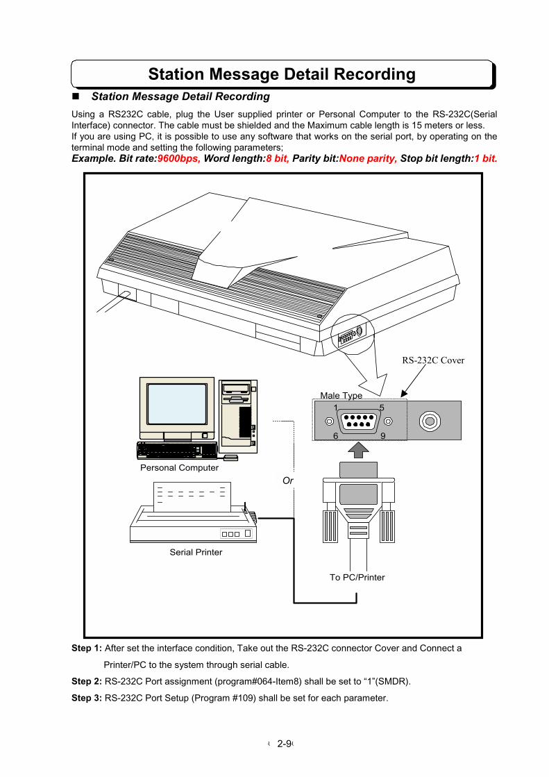
Station Message Detail Recording" Station Message Detail Recording
Using a RS232C cable, plug the User supplied printer or Personal Computer to the RS-232C(SerialInterface) connector. The cable must be shielded and the Maximum cable length is 15 meters or less.If you are using PC, it is possible to use any software that works on the serial port, by operating on theterminal mode and setting the following parameters;Example. Bit rate:9600bps, Word length:8 bit, Parity bit:None parity, Stop bit length:1 bit.
Step 1: After set the interface condition, Take out the RS-232C connector Cover and Connect a
Printer/PC to the system through serial cable.
Step 2: RS-232C Port assignment (program#064-Item8) shall be set to “1”(SMDR).
Step 3: RS-232C Port Setup (Program #109) shall be set for each parameter.
To PC/Printer
Serial Printer
Personal Computer
1 5
6 9
Male Type
Or
RS-232C Cover

-2-10-
Connection for Serial interface cable
" Connections for serial interface cable
The connection for the Cable that links the TX-Z2 824 system and the PC/Printer are as shown below.
・9-pin connector pair 9-pin connector
・9-pin connector pair 25-pin connector
Signal Name Pin No.RXD
TXD
DTR
SG
DSR
RTS
CTS
2
3
4
5
6
7
8
TX-Z2 System
Signal NamePin No.RXD
TXD
DTR
SG
DSR
RTS
CTS
2
3
4
5
6
7
8
PC/Printer
Male Type
1 5
6 9
TX-Z2 System
Signal Name Pin No.RXD
TXDDTR
SG
DSR
RTS
CTS
2
3
4
5
6
7
8
Signal NamePin No.
RXD
TXD
DTR
SG
DSR
RTS
CTS
2
3
45
6
7
PC/Printer
20
1 FG
Male Type
1 5
6 913 1
1425
-2-11-
Installing External MOH and BGM
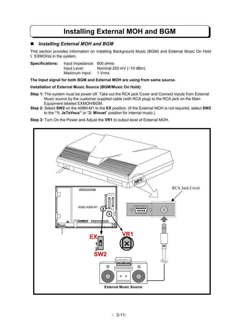
" Installing External MOH and BGM
This section provides information on installing Background Music (BGM) and External Music On Hold(EXMOH)in the system.
Specifications: Input Impedance: 600 ohmsInput Level: Nominal 250 mV (−10 dBm)Maximum Input: 1 Vrms
The Input signal for both BGM and External MOH are using from same source.
Installation of External Music Source (BGM/Music On Hold):
Step 1: The system must be power off. Take out the RCA jack Cover and Connect inputs from External Music source by the customer supplied cable (with RCA plug) to the RCA jack on the Main Equipment labeled EXMOH/BGM.Step 2: Select SW2 on the 408M-M1 to the EX position. (If the External MOH is not required, select SW2 to the “1: JeTeVeux“ or “2: Minuet” position for internal music.)
Step 3: Turn On the Power and Adjust the VR1 to output level of External MOH.
External Music Source
NX8E-408M-M1
SW2
EX12
VR1
RCA Jack Cover
-2-12-
Installing DHU-M1 PCB
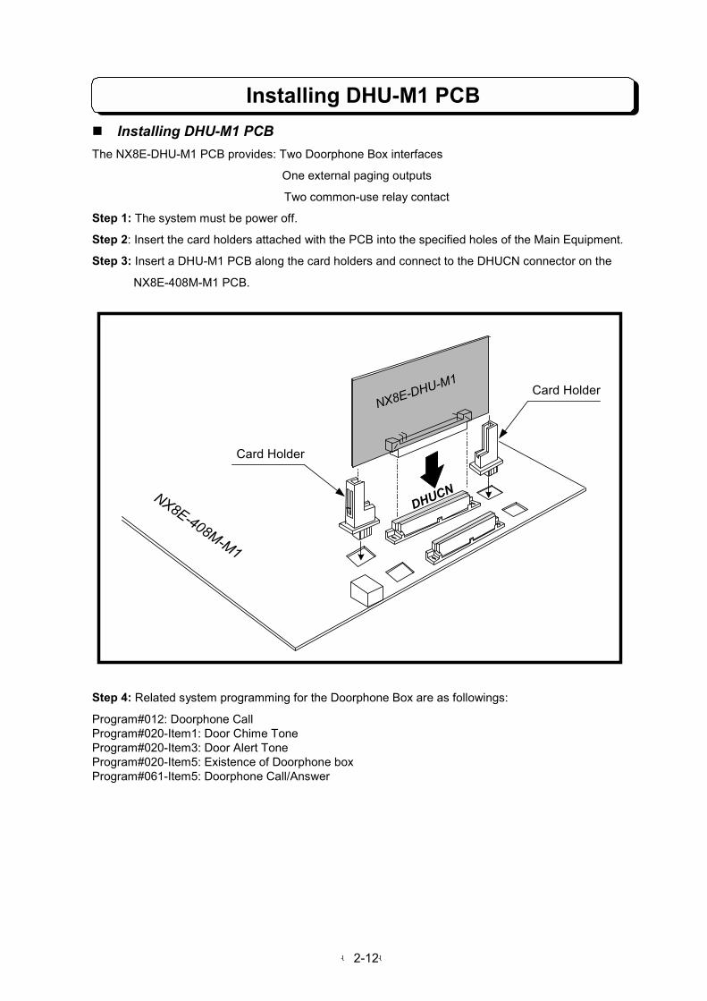
" Installing DHU-M1 PCB
The NX8E-DHU-M1 PCB provides: Two Doorphone Box interfaces
One external paging outputs
Two common-use relay contact
Step 1: The system must be power off.
Step 2: Insert the card holders attached with the PCB into the specified holes of the Main Equipment.
Step 3: Insert a DHU-M1 PCB along the card holders and connect to the DHUCN connector on the
NX8E-408M-M1 PCB.
Step 4: Related system programming for the Doorphone Box are as followings:
Program#012: Doorphone CallProgram#020-Item1: Door Chime ToneProgram#020-Item3: Door Alert ToneProgram#020-Item5: Existence of Doorphone boxProgram#061-Item5: Doorphone Call/Answer
NX8E-DHU-M1
NX8E-408M-M1
Card Holder
Card Holder
DHUCN

-2-13-
Installing the Doorphone Box
" Installing the Doorphone Box
This section provides information on installing the Doorphone Boxes in a TX-Z2 824 system.
Specifications: 150 m wire maximum of 0.5 φ twisted telephone cable.
Step 1: The system must be power off. Mount the DHU-M1 PCB on the base unit of the Main Equipment(see "Installing the DHU-M1 PCB" on page2-12).
Step 2: Connect wires to the terminal marked R and C on the back of the Doorphone Box, and connectthe other end to DH1 on the DHU-M1 PCB for Doorphone Box 1 or DH2 for Doorphone Box 2. (Seeillustration below)
RL2 RL1 CTR SPK DH2 DH1
DHUCN
RL1 CTR SPK DH2RL2 DH1CN1 CN2
R
C
Screw Holes for Wall Mount
To DH2
Rear view of NT-S-D6 Doorphone box
Doorphone BoxDoorphone Box
NX8E-DHU-M1 PCB
!!Pay attention to the polarity for R terminal and C terminal.

-2-14-
Installing External Paging Output" Installing External Paging Output
This section provides information on the installation of external devices to the external zone. A zonecan receive Trunk Audible, BGM and Paging. Speaker can be used to broadcast these signals at thezone. External page zone can be used to provide Meet-Me Paging. External zone have normally opencontacts. The relay for the zone is energized when Paging amplifier is in use, including Trunk audible andBGM (if programmed).
Specifications: Output Impedance: 600 ohmsOutput Level: Nominal 250 mV (−10 dBm)Maximum Output: 400 mV RMSRelay Contact: 1.25 amps for 24 V DC resistive loads
Step 1: Mount the DHU-M1 PCB on the base unit of the Main Equipment (see "Installing the DHU-M1PCB" on page 2-12).
Step 2: Connect wires from the connector on the DHU-M1 PCB labeled SPK to an amplifier for ExternalZone 1. The amplifier input must match the specifications above. Attach the speaker to your amplifier.
Step 3: Connect wires from the connector on the DHU-M1 PCB labeled CTR to the device for ExternalZone 1.
Step 4: Adjust the volume level of External Zone 1 with amplifier.
RL2 RL1 CTR SPK DH2 DH1
DHUCN
RL1 CTR SPK DH2RL2 DH1CN1 CN2
Paging Speaker
Amplifier
SPK: External paging audio signal output
CTR: Normally open relay contacts.If a zoneis activated,the contacts close.
NX8E-DHU-M1 PCB

-2-15-
CR2032
+
Installing External Device Control
Lithium Battery Installation
" Installing External Device Control
Door Lock control device can be connected to the TX-Z2 824 system.
1) Connect wires from Door Lock Control device to RL1/RL2 connector on the DHU-M1 PCB.
The remote control terminal on the External device also be connected to these contacts.(See Program056: Relay Contact Assignment)
The system is composed by two relays, every one of each having a normally opened contact.
" Lithium Battery InstallationLocate and remove the lithium battery in the center of NX8E-408M-M1 PCB. Remove the old battery andreplace it with the new battery as illustration. The battery, when fully charged, will retain memory contentsfor approximately 24 months or more.
Battery Type: SONY CR2032 Lithium Battery
CAUTION
1. The battery may explode if they are not replaced properly.
2. Never replace with battery other than the ones specified by the manufacturer (battery of the same type or the equivalent).
3. Dispose of spent batteries as instructed by the manufacturer of the battery.
* "B" flashes on the display of the Key Telephone whensystem battery is low. Replace it with the new battery. (Ifbattery is not installed in the system, "B" is not indicated onthe display.)
RL2 RL1 CTR SPK DH2 DH1
DHUCN
RL1 CTR SPK DH2RL2 DH1CN1 CN2
Door Lock ControlDevice
Door Lock ControlDevice
NX8E-DHU-M1 PCB
BAT

-2-16-
Backup Battery Connection
" Backup Battery Connection
The Battery Backup Box provides power during a power failure.Backup Duration: Approximately 1 hr. (depending on traffic)
Battery: Yuasa NP2.6-12 (rated at 12 volts, 2.6 amp-hours)
The Battery Backup Box may be wall- or floor-mounted. After mounting Battery Backup Box, follow thesesteps to install batteries and connect the cable:
Step 1: DC Switch and AC Switch must be turned off.Step 2: Insert one pair of batteries. (Batteries should always be installed and replaced in pairs).Step 3: Secure batteries with tie-wraps supplied.Step 4: Using battery terminal screws, connect the wiring to the battery terminals. Use the red wire toconnect the positive terminal of one battery to the negative terminal of the other battery. (See illustrationbelow)Step 5: With 2-wire connecting cable, connect Battery Backup Box to the connector marked "CN2" onthe Power Supply PCB installed in the Main Equipment.Step 6: AC switch and DC Switch must be turned On.
Red Orange Blue
+ +- -
ROMU DHU MODEMU
ETH
280mm
CN2++++ ----
POWER SUPPLY
155m
m
DC Power SW
AC Power SW
-2-17-
Power Failure Transfer
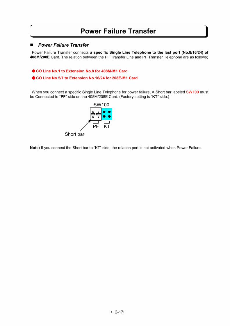
" Power Failure Transfer
Power Failure Transfer connects a specific Single Line Telephone to the last port (No.8/16/24) of408M/208E Card. The relation between the PF Transfer Line and PF Transfer Telephone are as follows;
CO Line No.1 to Extension No.8 for 408M-M1 Card
CO Line No.5/7 to Extension No.16/24 for 208E-M1 Card
When you connect a specific Single Line Telephone for power failure, A Short bar labeled SW100 mustbe Connected to “PF” side on the 408M/208E Card. (Factory setting is “KT” side.)
Note) If you connect the Short bar to “KT” side, the relation port is not activated when Power Failure.
SW100
PF KT
Short bar

-2-18-
Installing DLS Console
" Installing DLS Console
To install the DLS Console(BDL DSL for 2nd Model TEL):
Step 1: Turn the telephone upside down and remove the four screws from each comer.Step 2: Lift the upper housing off the telephone base.Step 3: On the lower housing, use a blunt object to remove the plastic filter piece that covers the hole for DLS connector.Step 4: Install the DLS Connector cable from the back of lower housing.Step 5: Insert the connectors on the DLS cable into the connectors DLCN1 and DLCN2 on the NX7E-ANU-B PCB in the upper housing.Step 6: Re-assemble the telephone and re-insert the four screws removed in step 1.Step 7: Mount the metal bracket between the telephone and DLS console and secure it with four screws provided.
Remove the plastic filter
DLS Console
DLCN2 DLCN1

PART 3
FEATURE DESCRIPTIONAND OPERATION
Table of Contents
Trunk Outgoing Call ...........................................................................................3-1
Specified Trunk Access ....................................................................................3-1
Last Number Dialing (LND)...............................................................................3-2
Saved Last Number Dialing (SLND) .................................................................3-3
Abbreviated Dialing...........................................................................................3-3
One-Touch Dialing ............................................................................................3-4
Toll Restriction ..................................................................................................3-5
Walking Toll Restriction ....................................................................................3-6
Dial Block ..........................................................................................................3-7
Flash..................................................................................................................3-8
Pulse to Tone Conversion.................................................................................3-8
Camp-On (Trunk Queuing) ...............................................................................3-9
Key Touch Tone................................................................................................3-9
Easy Trunk Access .........................................................................................3-10
Queuing Group Access...................................................................................3-10
Automatic Repeat Dialing ...............................................................................3-11
Loop Key Trunk Access ..................................................................................3-11
Automatic Off-Hook Trunk Access..................................................................3-12
Account Code..................................................................................................3-13
Trunk Incoming Call .........................................................................................3-14
Incoming Trunk Access...................................................................................3-14
Trunk Off-Hook Signaling................................................................................3-14
Ringing/Recall Trunk Off-Hook Access ..........................................................3-15
Night Service (Manual/Auto) ...........................................................................3-15
Call Forward....................................................................................................3-16
Follow Me........................................................................................................3-18
Call Pickup ......................................................................................................3-19
Do Not Disturb (DND) .....................................................................................3-19
Executive DND................................................................................................3-19
DISA (Extension Access)................................................................................3-20
Hold/Transfer/During Conversation .............................................................3-21
Hold .................................................................................................................3-21
Music On Hold.................................................................................................3-22
External Music On Hold ..................................................................................3-23
Transfer ...........................................................................................................3-23
Park Hold.........................................................................................................3-26
Conference......................................................................................................3-26
Long Conversation Warning (Three Minutes).................................................3-29
Long Conversation Cut-Off .............................................................................3-29
Break-In...........................................................................................................3-29

Other Trunk Features .......................................................................................3-31
PBX Compatibility ...........................................................................................3-31
Dial Mode (Tone/Pulse) Selection ..................................................................3-31
Private Line .....................................................................................................3-32
Tenant Service ................................................................................................3-32
Unsupervised Conference ..............................................................................3-33
Call Timer ........................................................................................................3-33
DISA (Trunk-to-Trunk).....................................................................................3-34
Second Trunk Access Code for SLT ..............................................................3-35
Intercom Outgoing Call ...................................................................................3-36
Intercom Link Increase....................................................................................3-36
Intercom Call ...................................................................................................3-36
Direct Station Selection...................................................................................3-37
Intercom Off-Hook Signaling...........................................................................3-38
Group Hunt......................................................................................................3-38
Step Calling.....................................................................................................3-39
Camp-On (Callback) .......................................................................................3-40
Message Waiting.............................................................................................3-40
Paging .............................................................................................................3-42
Flexible Station Numbering.............................................................................3-44
Dual Handsfree Hotline...................................................................................3-45
Intercom Incoming Call ...................................................................................3-46
Intercom Answer .............................................................................................3-46
Call Pickup ......................................................................................................3-46
Meet-Me Answer Paging.................................................................................3-47
Meet-Me Conference Paging..........................................................................3-47
Do Not Disturb (DND) .....................................................................................3-47
Intercom Hold..................................................................................................3-48
Intercom Call Transfer.....................................................................................3-49
Call Forward....................................................................................................3-49
Follow Me........................................................................................................3-49
Executive DND................................................................................................3-50
Other Intercom Features .................................................................................3-51
BGM ................................................................................................................3-51
External Paging...............................................................................................3-51
Doorphone.......................................................................................................3-51
Door Lock Control ...........................................................................................3-52
Room Monitor..................................................................................................3-53
Alphanumeric Display TEL Features ...........................................................3-54
Multi-Language Display...................................................................................3-54
Text Message..................................................................................................3-54
Time and Date.................................................................................................3-59
Name Storing (Trunk & Station)......................................................................3-60
Directory Dialing..............................................................................................3-61
Alarm Clock.....................................................................................................3-62
Stopwatch........................................................................................................3-63
Busy Lamp Field .............................................................................................3-63
Other Features ...................................................................................................3-64
Handsfree (Speaker & Microphone) ...............................................................3-64
Lamp Shift Mode .............................................................................................3-65
Remind Call on SLT........................................................................................3-65
Station Message Detail Recording (SMDR) ...................................................3-66
DISA with Audio Guidance..............................................................................3-67
External Call Forward on DISA.......................................................................3-67
Hot Line ...........................................................................................................3-68
Call Charge SMDR Output..............................................................................3-69
One-Touch Feature Access ............................................................................3-71
Volume Control ...............................................................................................3-72
DLS Console ..................................................................................................3-73
Headset Operation ..........................................................................................3-74
Single Line Extension Dial Tone.....................................................................3-75
Special User Password...................................................................................3-75
Voice Mail Connection ...................................................................................3-76
Caller-ID ..........................................................................................................3-76
VAU ................................................................................................................3-76
FAX Transfer ..................................................................................................3-76
List of Information Display .............................................................................3-77
List of Dial Number Plan .................................................................................3-92
List of SMDR Printout Data.............................................................................3-98
DISA Operation Flowchart ............................................................................3-100
Trunk Outgoing Call
3-1
!!!! Specified Trunk Access
DESCRIPTION:Trunk (CO/PBX) lines can be grouped into a maximum of 30 groups. The line groups assigned to eachextension can be used for outgoing calls. Up to two outgoing line groups can be assigned to anextension. An extension user can place outside calls on a particular line group by pressing Line key ordialing line number.
STATION APPLICATION:KTS, SLT
OPERATION:To make an outside call on a particular line:<KTS>When the trunk line appears under a Line key:1. Lift handset or press SPK key.2. Press a Line key. Hear dial tone.3. Dial telephone number.
When the trunk line does not appear under a Line key:1. Lift handset or press SPK key. (See Note 1)2. Dial 9.
3. Dial two-digit line number. Hear dial tone.4. Dial telephone number.
<SLT>1. Lift handset. Listen for dial tone.2. Dial 0 or 9. (See Note 2)3. Dial two-digit line number. Hear dial tone.4. Dial telephone number.
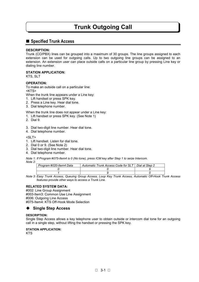
Note 1: If Program #075-Item4 is 0 (No tone), press ICM key after Step 1 to seize Intercom.Note 2:
Program #020-Item4 Data Automatic Trunk Access Code for SLT Dial at Step 20 0 91 9 0
Note 3: Easy Trunk Access, Queuing Group Access, Loop Key Trunk Access, Automatic Off-Hook Trunk Accessfeatures provide other ways to access a Trunk Line.
RELATED SYSTEM DATA:#002: Line Group Assignment#003-Item3: Common Use Line Assignment#006: Outgoing Line Access#075-Item4: KTS Off-Hook Mode Selection
" Single Step Access
DESCRIPTION:Single Step Access allows a key telephone user to obtain outside or intercom dial tone for an outgoingcall in a single step, without lifting the handset or pressing the SPK key.
STATION APPLICATION:KTS
Trunk Outgoing Call
3-2
OPERATION:To obtain outside dial tone using Single Step Access:
- Do not lift handset.1. Press a Line key. The Line key and SPK key light.
- Dial tone comes over the speaker.
To obtain intercom dial tone using Single Step Access:- Do not lift handset.
1. Press ICM key. ICM and SPK key light.- Dial tone comes over the speaker.
RELATED SYSTEM DATA:#015-Item5: Single Step Access
" Preselection
DESCRIPTION:This feature permits access to an Trunk or ICM call by lifting the handset or pressing the SPK key withinthree seconds of pressing a Line or ICM key.
STATION APPLICATION:KTS
OPERATION:1. Press a Line or ICM key.2. Lift handset or press SPK key within 3 sec.
- Trunk Line or Intercom is seized.
RELATED SYSTEM DATA:#015-Item5: Single step access
!!!! Last Number Dialing (LND)
DESCRIPTION:The last telephone number dialed on an outgoing call (trunk line) can be redialed. A maximum of 18 digitsare stored.
STATION APPLICATION:KTS, SLT
OPERATION:<KTS>1. Lift handset or press SPK key.2. Press a Line key.3. Press LND key.
<SLT>1. Lift handset.2. Dial function code. (See Note 1)3. Dial queuing group number. (See Note 2)
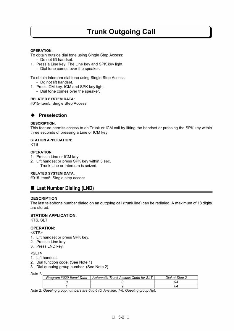
Note 1:Program #020-Item4 Data Automatic Trunk Access Code for SLT Dial at Step 2
0 0 941 9 04
Note 2: Queuing group numbers are 0 to 6 (0: Any line, 1-6: Queuing group No).

Trunk Outgoing Call
3-3
RELATED SYSTEM DATA:#033: LND/Repeat Dial Hooking Time#064-Item3: Trunk Line Seizing Order Selection
!!!! Saved Last Number Dialing (SLND)
DESCRIPTION:This feature permits saving the last number dialed for redialing at a later time. The saved telephonenumber remains in memory until another is stored in it's place.
STATION APPLICATION:KTS
OPERATION:To place an outside call using saved last number:1. Lift handset or press SPK key.2. Press a Line key.3. Press DC key and #.
orPress One Touch key.
To store dialed number as saved last number:1. While talking on trunk line.2. Press DC key twice before terminating a call.
orPress One Touch key before terminating a call.
To set One-Touch key as SLND key:1. Press SPK key.2. Press ICM key. (See Note 1)3. Press DC key and ∗ .4. Press One Touch key.5. Press OPAC key and #.6. Press SPK key.
Note 1: If Program #075-Item4 is 0 (No tone), skip Step 2.Note 2: One Touch key #10 is set as SLND key initially.
RELATED SYSTEM DATA:Not applicable.
!!!! Abbreviated Dialing
DESCRIPTION:The system provides common-use abbreviated dialing. Abbreviated Dialing allows storage of up to 100or 200 locations 18 digit telephone number under 2 or 3 digit codes (00 to 99 or 000 to 199).The user can select the storage quantity of Abbreviated Dial in Program #017-Item4.
STATION APPLICATION:KTS, SLT

Trunk Outgoing Call
3-4
OPERATION:To place an outside call:
<KTS>1. Lift handset or press SPK key.2. Press an idle Line key.3. Press DC key.4. Dial abbreviated number. (00 to 99) or (000 to 199)
<SLT>1. Lift handset.2. Dial function code. (See Note 1)3. Dial queuing group number (0 to 6). (See Note 2)4. Dial abbreviated number. (00 to 99) or (000 to 199)
Note 1:Program #020-Item4 Data Automatic Trunk Access Code for SLT Dial at Step 2
0 0 931 9 03
Note 2: Queuing group numbers are 0 - 6 (0: Any line, 1-6: Queuing group No).
To store abbreviated number(Extension #10 only):1. Press SPK key.2. Press ICM key. (See Note 1)3. Press DC key and ∗ .4. Dial abbreviated number. (00 to 99) or (000 to 199)5. Dial phone number to be stored. (see Note 2)6. Repeat steps 3 to 5.7. Press SPK key to exit from Abbreviated Dialing entry.
Note 1: If Program #075-Item4 is 0 (No tone), skip Step 2.Note 2: You can enter pauses (TRFR key), flashes (FLASH key) and stops (CONF key) when storing a Abbreviated
Dial number. Each pause, stop or flash counts as a digit when totaling the number of digits in a AbbreviatedDial number. When stop is inserted, dialing will be stopped this position and can be continued by dialing.
RELATED SYSTEM DATA:#017-Item4: Storage Quantity of Abbreviated Dial#018-Item3: Abbreviated Dialing Restriction
!!!! One-Touch Dialing
DESCRIPTION:One-Touch Dialing allows you to store ten of your most frequently called outside numbers as personalabbreviated dial numbers at your extension so you can call them with just a single touch. Dial number tobe stored is up to 18 digits including pauses (TRFR key), flashes (FLASH key) and stops (CONF key).The One Touch Dial numbers are stored under the ten One -Touch keys (No.1 to No.10) as F01 to F10.
When the number of common Abbreviated Dialing is set to 100 in Program #017-Item4, the memory forthe remaining 100 numbers can be used for personal abbreviated dial numbers at 10 Key telephones.The assigned Key Telephone user can store up to 10 more dial numbers under ten One-Touch Keys asF11 to F20. When dialing, the user must press OPAC key before pressing an One-Touch Key.
STATION APPLICATION:KTS

Trunk Outgoing Call
3-5
OPERATION:
<All KTS>To place an outside call:1. Seize a Trunk line.2. Press One Touch key which stores desired phone number.
To store a One Touch Dial number:1. Press SPK key.2. Press ICM key. (See Note 1)3. Press DC key and ∗ .4. Press a One -Touch key to store a phone number.5. Dial phone number to be stored. (One-Touch Key No.1 to No.10 store numbers in F01-F10.)6. Repeat steps 3 to 5.7. Press SPK key to exit from One-Touch Dialing entry.
<Only assigned KTS>To place an outside call:1. Seize a Trunk line.2. Press OPAC key.3. Press One-Touch key which stores the desired phone number.
To store a One-Touch Dial number:1. Press SPK key.2. Press ICM key. (See Note 1)3. Press DC key and ∗ .4. Press OPAC key.5. Press a One-Touch key to store a phone number. (One-Touch Key No.1 to No.10 store numbers in
F11-F20.)6. Dial phone number to be stored.7. Go to Step 3 to enter another number
orHang up or press SPK to finish.
To check stored One-Touch Dial number:
(On-hook condition)1. Press CHECK key.2. Press DC key and OPAC key.3. Press a One-Touch key which stores the phone number.4. Press CLEAR key to finish.
Note 1: If Program #075-Item4 is 0 (No tone), skip Step 2.Note2: If the above operations are taken without pressing OPAC key, the numbers stores in F1-F10 are
called.
RELATED SYSTEM DATA:#017-Item4: Storage Quantity of Abbreviated Dialing#075-Item2: Personal Abbreviated Dial
!!!! Toll Restriction
DESCRIPTION:Toll Restriction determines extension’s ability to make calls. Each extension can be assigned one of thefollowing six classes per mode (Day/Night). Toll Restriction Class A is the highest and the Class F is thelowest.

Trunk Outgoing Call
3-6
Class-A: No dialing restrictions.Class-B: Dials are restricted by DATA-B except dials matching PBX extension call or DATA-F.Class-C: Dials are restricted by DATA-D2 except dials matching PBX extension call, DATA-C, or DATA-
F.Class-D: Dials are restricted by DATA-D2 or DATA-D1 except dials matching PBX extension call or
DATA-F.Class-E: Dials are restricted all outgoing Trunk calls except dials matching PBX extension call or DATA-
F.Class-F: Intercom calls only.
The DATA (restricted/permitted codes and number length limit) within the Classes must be entered inprogramming.
If there are PBX lines, PBX access code must be assigned in programming in order for Toll Restriction tobe properly applied.
Toll restrictions are not applied to lines programmed as Unrestricted Lines.
When the system is placed in night mode by Night Service feature, the Toll Restriction class assignmentfor night mode is activated.
STATION APPLICATION:KTS, SLT
OPERATION:When an extension user dials a call that is not allowed by the assigned Class, the system automaticallydisconnects the line.
RELATED SYSTEM DATA:#003-Item4: Unrestricted Lines#018-Item3: Abbreviated Dialing Restriction#035-Item1: Toll Restriction Class (Day)#035-Item2: Toll Restriction Class (Night)#036: Class-B Restricted Codes (DATA-B)#037: Permitted Codes (DATA-C)#038: Number Length Limit (DATA-D1)#039: Class-C/D Restricted Codes (DATA-D2)#040: PBX CO Access Codes (DATA-E)#041: Common Unrestricted Codes (DATA-F)
!!!! Walking Toll Restriction
DESCRIPTION:Walking Toll Restriction lets you temporarily override an extension's dialing restrictions by dialingprogrammed security code at that extension. Dialing the code overrides the restrictions set up in TollRestriction.
STATION APPLICATION:KTS, SLT
OPERATION:<KTS>1. Lift handset.2. Press an idle Line key.3. Press OPAC key.4. Press DC key.5. Dial security code.6. Dial phone number.

Trunk Outgoing Call
3-7
<SLT>1. Lift handset.2. Dial 07 (or 97). => (See Note)3. Dial security code.4. Dial 9 (or 0). => (See Note)5. Dial phone number.
Note:Program #020-Item4 Data Automatic Trunk Access Code for SLT Dial at Step 2 Dial at Step 4
0 0 97 01 9 07 9
RELATED SYSTEM DATA:#042: Walking Toll Restriction Security Code#043: Toll Restriction Class Assignment on Security Code
!!!! Dial Block
DESCRIPTION:Dial Block allows you to temporally lock your extension by entering 4 digit personal code so that otherusers can not make outside calls from your extension. To have this facility each extension has to beassigned by system programming.At No Display Key Telephones, 3-Splash tone is emitted from built-in speaker if somebody tries to makean outside call while Dial Block is set.
STATION APPLICATION:KTS, SLT
OPERATION:To set Dial Block:<KTS>1. Press SPK key.2. Press ICM key. (See Note 1)3. Dial ∗ , #
4. Dial 4-digit personal code. (See Note 3)5. Dial ∗ .
- Confirmation tone when effective.- Error tone when not effective.
6. Press SPK key.
<SLT>1. Lift handset.2. Dial function code. (See Note 2)3. Dial 4-digit personal code. (See Note 3)4. Replace handset.
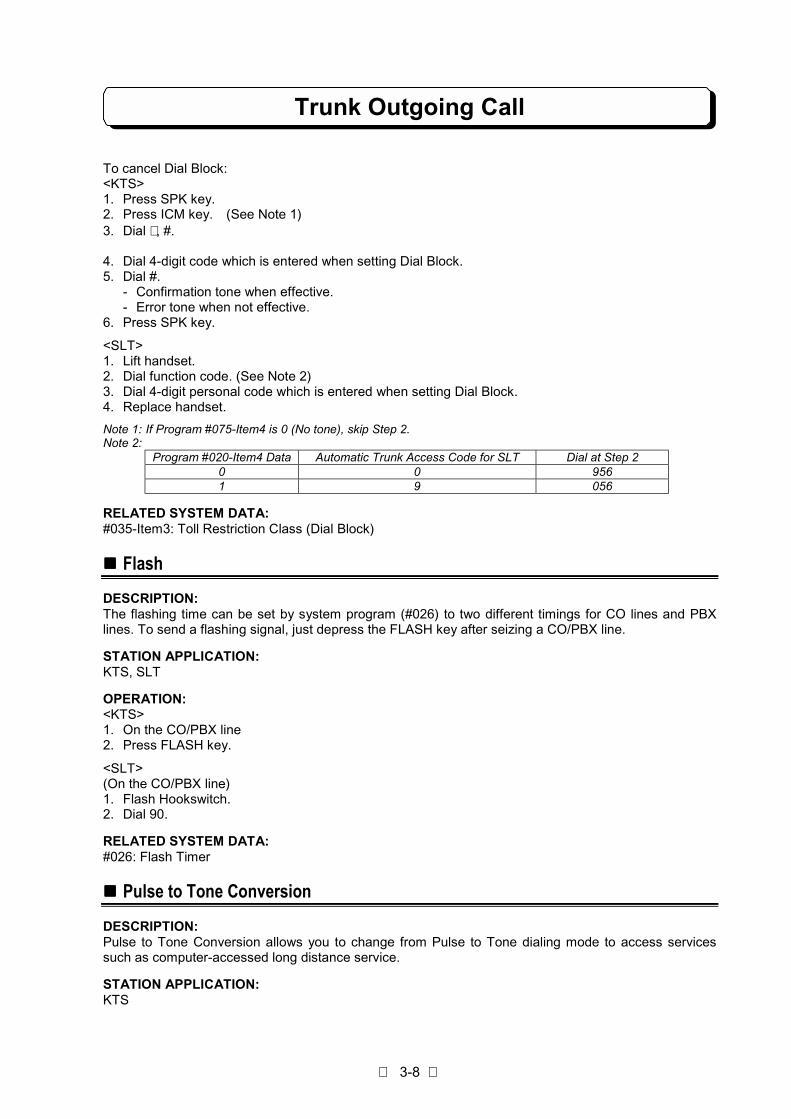
Note 1: If Program #075-Item4 is 0 (No tone), skip Step 2.Note 2:
Program #020-Item4 Data Automatic Trunk Access Code for SLT Dial at Step 20 0 9551 9 055
Note 3: You can dial any number as a personal code.
Trunk Outgoing Call
3-8
To cancel Dial Block:<KTS>1. Press SPK key.2. Press ICM key. (See Note 1)3. Dial ∗ , #.
4. Dial 4-digit code which is entered when setting Dial Block.5. Dial #.
- Confirmation tone when effective.- Error tone when not effective.
6. Press SPK key.
<SLT>1. Lift handset.2. Dial function code. (See Note 2)3. Dial 4-digit personal code which is entered when setting Dial Block.4. Replace handset.
Note 1: If Program #075-Item4 is 0 (No tone), skip Step 2.Note 2:
Program #020-Item4 Data Automatic Trunk Access Code for SLT Dial at Step 20 0 9561 9 056
RELATED SYSTEM DATA:#035-Item3: Toll Restriction Class (Dial Block)
!!!! Flash
DESCRIPTION:The flashing time can be set by system program (#026) to two different timings for CO lines and PBXlines. To send a flashing signal, just depress the FLASH key after seizing a CO/PBX line.
STATION APPLICATION:KTS, SLT
OPERATION:<KTS>1. On the CO/PBX line2. Press FLASH key.
<SLT>(On the CO/PBX line)1. Flash Hookswitch.2. Dial 90.
RELATED SYSTEM DATA:#026: Flash Timer
!!!! Pulse to Tone Conversion
DESCRIPTION:Pulse to Tone Conversion allows you to change from Pulse to Tone dialing mode to access servicessuch as computer-accessed long distance service.
STATION APPLICATION:KTS

Trunk Outgoing Call
3-9
OPERATION:1. Dial phone number. (Pulse mode).2. Dial #.3. Dial phone number. (Tone mode).
RELATED SYSTEM DATA:#001-Item2: Dial Mode
!!!! Camp-On (Trunk Queuing)
DESCRIPTION:When all trunk lines in a particular Queue Group are busy, Camp-On puts an extension user on a"waiting list" for an available line in the group. As soon as a line becomes free, the user's phone rings anda Line key flashes. Up to eight extension users can activate Camp-On in the same Queue Group. Whensignaled, the user must answer within 20 sec, otherwise the line rings the next extension on the "waitinglist".
STATION APPLICATION:KTS, SLT
OPERATION:To use Camp-On:<KTS>1. Lift handset.2. Press ICM key. (See Note)3. Press HOLD key.4. Dial Queuing Group number (0-6) (0: Same group, 1- 6: Group No.).
- If you hear busy tone, the extension can not use Camp-On for that group.5. Replace handset.
<SLT>1. Place an outside call. Hear busy tone.2. Dial Queuing Group number (0-6) (0: Same group, 1- 6: Group No.).3. Replace handset.
Note : If Program #075-Item4 is 0 (No tone), skip Step 2.
When Camp-On rings an extension:<KTS>1. Lift handset.2. Press flashing Line key.
<SLT>1. Lift handset.
RELATED SYSTEM DATA:#001-Item3: Queuing Group - Line Assignment#016-Item2: Recall Trunk Off-Hook Access
!!!! Key Touch Tone
DESCRIPTION:The Key Touch Tone feature allows a tone to be emitted from the built-in speaker each time a Line,One-Touch or dial pad key is pressed. The tone confirms the key was fully pressed.
STATION APPLICATION:KTS

Trunk Outgoing Call
3-10
OPERATION:To activate Key Touch Tone:
- Do not lift handset.1. Dial ∗ .
To cancel Key Touch Tone:- Do not lift handset.
1. Dial ∗ . Final Key Touch Tone is heard.
RELATED SYSTEM DATA:#013-Item1: Key Touch Tone
!!!! Easy Trunk Access
DESCRIPTION:Easy Trunk Access lets an extension user access an outgoing line without pressing a Line key or dialinga two-digit line number. A single-digit code automatically accesses an outgoing outside line from smallernumber, large number, or rotated number.
STATION APPLICATION:KTS, SLT
OPERATION:To access the first available outgoing line:<KTS>1. (On-Hook and Speaker off condition)2. Dial 0. A line is seized and dial tone comes over the speaker.
<SLT>1. Lift handset.2. Dial 9 or 0. (refer to Program #020-Item4)
RELATED SYSTEM DATA:#015-Item3: Automatic Trunk Access#020-Item4: Automatic Trunk Access Code for SLT#064-Item3: Trunk Line Seizing Order Selection
!!!! Queuing Group Access
DESCRIPTION:Queuing Group Access lets an extension user access the first available outgoing line in a Queuing Groupwithout pressing a Line key or dialing a two-digit line number. A single-digit code automatically accessesan outgoing outside line from small number, large number, or rotated number.
STATION APPLICATION:KTS, SLT
OPERATION:
To access the first available line in a Queuing Group:<KTS>1. Press SPK key.2. Press ICM key. (See Note)
3. Dial Queuing Group number (1-6). A line is seized and dial tone comes over the speaker.

Trunk Outgoing Call
3-11
<SLT>1. Lift handset.2. Dial 06 or 96 (refer to #020-Item4)3. Dial Queuing Group number (1-6)
Note 1: If Program #075-Item4 is 0 (No tone), skip Step 2.
RELATED SYSTEM DATA:#001-Item3: Queuing Group - Line Assignment#015-Item3: Automatic Trunk Access#020-Item4: Automatic Trunk Access Code for SLT#064-Item3: Trunk Line Seizing Order Selection
!!!! Automatic Repeat Dialing
DESCRIPTION:If an extension user places a trunk call that is busy or unanswered, they can have Automatic RepeatDialing try it again later on. The user doesn't continually have to try the number again -- hoping it will gothrough. Automatic Repeat Dialing automatically retries it until the called party answers. Moreover, whileAutomatic Repeat Dialing is set (waiting, busy or no-answer), Hurry-Up operation can be taken place forimmediate redial.While Automatic Repeat Dialing is set (waiting condition), 2-Splash tone (Mute-tone) is emitted frombuilt-in speaker in 5 sec cycle.
STATION APPLICATION:KTS
OPERATION:To use Automatic Repeat Dialing:1. Place outside call.
- Listen for busy tone or ring-no-answer.2. Press OPAC key.3. Dial 1.4. Replace handset or press SPK key.
- The system periodically redials the call.
To cancel Automatic Repeat Dialing:1. Lifting the handset cancels Automatic Repeat Dialing.
To use Hurry-Up operation1. Press OPAC key.2. Dial 2.
Repeat Dialing and Hurry-Up Operation can be stored under One-touch key.
RELATED SYSTEM DATA:#001-Item3: Queuing Group - Line Assignment#033: LND/Repeat Dial Hooking Time#034: Repeat Dial Timers
!!!! Loop Key Trunk Access
DESCRIPTION:User can assign only one Loop Key to one of undefined Line keys. The Loop Key should be assigned onan unused Line key in advance by using "One-Touch Feature Access". This feature permits access to anoutgoing line by pressing a Loop Key. The trunk line is seized from small number, large number, orrotated number. This key provides user advantage as follows;

Trunk Outgoing Call
3-12
- When the number of Trunk lines connected to the system is larger than the number of Line keys atuser's KTS, user can seize all the Trunk line by pressing the Loop key.
- User can use the Park Hold effectively.
There are 6 types of LED indication.- System Hold: 0.1 sec ON / 0.1 sec OFF (BLF: Green)- Exclusive Hold: 0.1 sec ON / 0.1 sec OFF / 0.1 sec ON / 0.7 sec OFF (BLF: Green)- I-Use: Light (BLF: Green)- Conference standby: 0.1 sec ON / 0.1 sec OFF / 0.1 sec ON / 0.7 sec OFF (BLF: Green)- Idle: Extinguish- All lines are Busy: Light (BLF: Red)
STATION APPLICATION:KTS
OPERATION:To seize a Trunk line:1. Press Loop Key. (Dial Tone is heard.)* Refer to One-Touch Feature Access for how to assign Loop Key.
To answer the incoming call:(This feature is available for KTS which is allowed Ringing Trunk Off-hook Access feature.)1. Incoming call to a Trunk line. (Ringing)
(Loop key is still extinguished.)2. Lift handset. (Loop key lights Green.)
RELATED SYSTEM DATA:#064-Item3: Trunk Line Seizing Order Selection
!!!! Automatic Off-Hook Trunk Access
DESCRIPTION:The assigned extension users can seize an idle Trunk Line by only lifting handset. The operations suchas pressing Line key or dialing Trunk Access Code become unnecessary. This feature is useful for KeyTelephone users who mainly makes outside calls, or to connect Fax Machines (Modems) instead ofSingle Line Telephones.
STATION APPLICATION:KTS, SLT
OPERATION:<KTS>1. Lift handset or press SPK key. (An idle Trunk Line will automatically be seized.)Note 1: If all Trunk Lines are busy, no tone will be heard.Note 2: This disables the user to seize Intercom after lifting handset. Press ICM key before lifting handset to seize
Intercom.Note 3: Lifting handset when the extension is ringing answers Trunk Line or Intercom call.
<SLT>1. Lift handset. (An idle Trunk Line will automatically be seized.)Note : If all Trunk Lines are busy, Busy Tone will be heard.Note 2: Assigned SLT user can not place Intercom Calls. However, they can receive incoming Intercom Call and
transferred Trunk Line Call. Transferring Trunk Line calls to another extension is possible.
RELATED SYSTEM DATA:#064-Item3: Trunk Line Seizing Order Selection#075-Item3: SLT Automatic Trunk Access#075-Item4: KTS Off-Hook Mode Selection
Trunk Outgoing Call
3-13
!!!! Account Code
DESCRIPTION:Account Code is useful to keep track of expenditures. Extension user dials Account Code before makingoutside call. This code is shown on the SMDR print out.
STATION APPLICATION:KTS, SLT
OPERATION:To enter the Account Code:<KTS>1. Seize an idle Trunk Line. (Hear Dial Tone.)2. Dial ∗ .3. Dial Account Code. (Max. 8 digits)4. Dial ∗ .5. Dial Telephone Number.
<SLT>1. Seize an idle Trunk Line. (Hear Dial Tone.)2. Flash Hookswitch.3. Dial 99.4. Dial Account Code. (Max. 8 digits)5. Flash Hookswitch.6. Dial Telephone Number.
RELATED SYSTEM DATA:#078-Item9: KTS Account Code#057-Item6: SLT Account Code

Trunk Incoming Call
3-14
!!!! Incoming Trunk Access
DESCRIPTION:Trunk lines can be grouped into a maximum of 30 groups. The line groups assigned to each extensioncan access for incoming calls and the audible assignments (day and/or night mode ringing) for theextensions. Up to two incoming line groups can be assigned to an extension. An extension user cananswer an incoming call on a particular line group only if the extension has Incoming Trunk Access tothat group. When an extension is assigned incoming access to a line group, the lines in the group appearunder the Line keys (KTS).
STATION APPLICATION:KTS, SLT
OPERATION:<KTS>To answer an outside call by Direct Pickup:1. Lift handset or press SPK key.2. Press flashing Line key.
To answer an outside call by Dial Pickup:1. Lift handset or press SPK key. (See Note)2. Dial 96.
Note: If Program #075-Item4 is 0 (No tone), press ICM key after Step 1 to seize Intercom.
<SLT>1. Lift handset.2. Dial 06 or 96. (Refer to #020-Item4)3. Dial 0.
RELATED SYSTEM DATA:#002: Line Group Assignment#003-Item3: Common Use Line Assignment#007: Incoming Trunk Access/Audible#016-Item1: Ringing Trunk Off-Hook Access
!!!! Trunk Off-Hook Signaling
DESCRIPTION:Trunk Off-Hook Signaling provides an extension user with an audible indication of an incoming Trunk callwhile already on a call: the busy extension user hears muted ringing if on a handset call or one shortburst tones (0.5s ON/15s OFF) if on a Handsfree call.
STATION APPLICATION:KTS
OPERATION:To answer a Trunk Off-Hook signal:1. Press HOLD to put an outside call in progress on hold or hang up the call in progress. Intercom calls
must be hung up since they cannot be put on hold.2. Press the flashing Line key.
RELATED SYSTEM DATA:#004-Item2: Trunk Off-Hook Signaling

Trunk Incoming Call
3-15
!!!! Ringing/Recall Trunk Off-Hook Access
DESCRIPTION:Ringing Trunk Off-Hook Access allows a ringing outside call to be answered by just lifting the handset; aLine key does not have to be pressed. Recall Trunk Off-Hook Access lets a recalling (re-ringing) line beanswered by just lifting the handset.
STATION APPLICATION:KTS, SLT
OPERATION:1. Lift handset.
RELATED SYSTEM DATA:#016-Item1: Ringing Trunk Off-Hook Access#016-Item2: Recall Trunk Off-Hook Access
!!!! Night Service (Manual/Auto)
DESCRIPTION:Night Service puts the night audible (ringing) assignment (Program #007) into effect manually orautomatically. Incoming calls on a specific line group will ring at extensions that are assigned nightaudible for that line group. Night Service remains set even if the system power is turned off.
Night Service is available on a system basis or incoming line group basis according to Program #015-Item2.
1. Night audible assignments go into effect at all extensions in the system. Day audible assignments areignored. The extension #10 can activate this Night Service (NT) mode.
2. Night audible assignments go into effect for the extensions that have the same primary incoming linegroup as the extension that activates this NT mode. Extensions with a different primary incoming linegroup receive ringing according to their day audible assignments. Any extension can activate thismode.This NT mode can be activated by any extension in each same primary incoming line group.
Automatic Mode SwitchingAutomatic Mode Switching (Program #079) allows to switch Day/Night mode according topreprogrammed time routine for the system. When Automatic Mode Switching places the system in NightMode, TRFR blinks red at all key telephones. If the system mode is switched manually at No.10telephone, it overrides Automatic Mode Switching assignment.
STATION APPLICATION:KTS, SLT, External speaker, Doorphone
OPERATION:To activate Night Service:<KTS>1. Press SPK key.2. Press ICM key. (See Note)3. Press TRFR key.4. Dial #. TRFR lights red.5. Hang up.
Trunk Incoming Call
3-16
To activate Night Service:
<DSS>1. Press NT key. (LED lights red)
To cancel Night Service:
<KTS>1. Press SPK key.2. Press ICM key. (See Note)3 Press TRFR key.4. Dial #. TRFR extinguishes.5. Hang up.
To cancel Night Service:
<DSS>1. Press NT key. (LED extinguishes)
This feature can be stored under the One-touch key.
When NT mode 1 is enabled, the TRFR key lights steadily at all KTSs. When NT mode 2 is enabled, the TRFR keylights steadily at the activating extension and at all other KTSs with the same primary incoming line group.
Note: If Program #075-Item4 is 0 (No tone), skip Step 2.
RELATED SYSTEM DATA:#007: Incoming Trunk Access/Audible#015-Item2: Night Service#079: Automatic Mode Switching Time
!!!! Call Forward
DESCRIPTION:Call Forward reroutes an extension user's incoming outside calls so they ring at a different extension. Anextension user who activates Call Forward does not lose access to incoming calls. Incoming access isshared with the receiving (destination) extension, but only the destination extension rings. There is nolimit in number of extensions which set Call Forward to a same destination. Calls cannot be rerouted toan extension in Do Not Disturb. There are four types of Call Forward:
- Call Forward ImmediateAll calls transferred immediately to the destination.
- Call Forward when BusyCalls are transferred only when the extension is busy.
- Call Forward when UnansweredCalls are transferred only if they are unanswered, and both the destination and the transferringextension ring.
- Call Forward when Busy/UnansweredCalls are transferred only when the extension is busy or unanswered, and both the destination and thetransferring extension ring.
STATION APPLICATION:KTS, SLT

Trunk Incoming Call
3-17
OPERATION:To activate Call Forward:<KTS>1. Press SPK key.2. Press ICM key. (See Note 1)3. Press TRFR key.4. Dial destination extension number.5. Dial option code (0-3). (see Note 3)
- One short beep sounds as confirmation.- 3 splash tone means calls cannot be rerouted to that extension.
6. Press SPK key.
<SLT>1. Lift handset.2. Dial function code. (see Note 2)3. Dial destination extension number.4. Dial option code (0-3). (see Note 3)5. Hang up.
Note 1: If Program #075-Item4 is 0 (No tone), skip Step 2.Note 2:
Program #020-Item4 Data Automatic Trunk Access Code for SLT Dial at Step 20 0 9531 9 053
Note 3: Option codes are as follows:0 => Call Forward Immediate1 => Call Forward when Busy2 => Call Forward when Unanswered3 => Call Forward when Busy/Unanswered
To cancel Call Forward (at originating and destination extension):<KTS>1. Press SPK key.2. Press ICM key. (See Note 1)3. Press TRFR key twice.4. Press SPK key.
<SLT>1. Lift handset.2. Dial function code. (see Note 2)3. Hang up.
Note 1: If Program #075-Item4 is 0 (No tone), skip Step 2.Note 2:
Program #020-Item4 Data Automatic Trunk Access Code for SLT Dial at Step 20 0 9591 9 059
RELATED SYSTEM DATA:#028: Unanswered Time

Trunk Incoming Call
3-18
!!!! Follow Me
DESCRIPTION:When an extension user is away from his/her extension and has to use another extension, Follow Mereroutes the extension user's incoming outside calls to that extension. There are four types of Follow Mesame as Call Forward.
- Follow Me ImmediateAll calls transferred immediately to the destination.
- Follow Me when BusyCalls are transferred only when the extension is busy.
- Follow Me when UnansweredCalls are transferred only if they are unanswered, and both the destination and the transferringextension ring.
- Follow Me when Busy/UnansweredCalls are transferred only when the extension is busy or unanswered, and both the destination and thetransferring extension ring.
STATION APPLICATION:KTS, SLT
OPERATION:To activate Follow Me (at another extension) :<KTS>1. Press SPK key.2. Press ICM key. ( See Note 1)3. Press TRFR key and dial 0.4. Dial originating extension number (your extension No.).5. Dial option code (0-3). (see Note 3)
- One short beep sounds as confirmation.- 3 splash tone means calls cannot be rerouted to that extension.
6. Press SPK key.
<SLT>1. Lift handset.2. Dial function code. (see Note 2)3. Dial originating extension number (your extension No.).4. Dial option code (0-3). (see Note 3)5. Hang up.
Note 1: If Program #075-Item4 is 0 (No tone), skip Step 2.Note 2:
Program #020-Item4 Data Automatic Trunk Access Code for SLT Dial at Step 20 0 95301 9 0530
Note 3: Option codes are as follows:0 => Follow Me Immediate1 =>Follow Me when Busy2 => Follow Me when Unanswered3 => Follow Me when Busy/Unanswered
Trunk Incoming Call
3-19
To cancel Follow Me (at originating and destination extension):<KTS>1. Press SPK key.2. Press ICM key. (See Note1)3. Press TRFR key twice.4. Press SPK key.
<SLT>1. Lift handset.2. Dial function code. (see Note 2)3. Hang up.
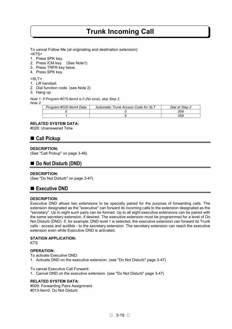
Note 1: If Program #075-Item4 is 0 (No tone), skip Step 2.Note 2:
Program #020-Item4 Data Automatic Trunk Access Code for SLT Dial at Step 20 0 9591 9 059
RELATED SYSTEM DATA:#028: Unanswered Time
!!!! Call Pickup
DESCRIPTION:(See "Call Pickup" on page 3-46)
!!!! Do Not Disturb (DND)
DESCRIPTION:(See "Do Not Disturb" on page 3-47)
!!!! Executive DND
DESCRIPTION:Executive DND allows two extensions to be specially paired for the purpose of forwarding calls. Theextension designated as the "executive" can forward its incoming calls to the extension designated as the"secretary". Up to eight such pairs can be formed. Up to all eight executive extensions can be paired withthe same secretary extension, if desired. The executive extension must be programmed for a level of DoNot Disturb (DND). If, for example, DND level 1 is selected, the executive extension can forward its Trunkcalls - access and audible - to the secretary extension. The secretary extension can reach the executiveextension even while Executive DND is activated.
STATION APPLICATION:KTS
OPERATION:To activate Executive DND:1. Activate DND on the executive extension. (see "Do Not Disturb" page 3-47)
To cancel Executive Call Forward:1. Cancel DND on the executive extension. (see "Do Not Disturb" page 3-47)
RELATED SYSTEM DATA:#009: Forwarding Pairs Assignment#013-Item2: Do Not Disturb

Trunk Incoming Call
3-20
!!!! DISA (Extension Access)
DESCRIPTION:Direct Inward System Access (DISA) lets someone outside the system call in on a DISA Line and directlyaccess an extension or access the Group Hunt feature - in each case, bypassing the system operator. Incase outside caller does not dial extension number within the time which is set in Program #066-Item2 orcalled extension is busy, or called extension does not answer within the time which is set in Program#066-Item3, this call will be transferred to operator telephone (pre-assigned extension in Program #051).Attendant extension can be assigned for Day mode and Night mode respectively. The DISA line areautomatically terminated within the time which is set in Program #066-Item3/Item5 when calls areunauthorized, or calls transferred to operator are unanswered. The DISA caller must use a DTMFtelephone.
When Trunk line is assigned as DISA Line in Program #003-Item1, DISA port can be allocated to anyone of DISA line which must be programmed in Program #008-Item1 with data 1".
During Automatic Answer Time (Program #066-Item1), the system indicates LED either busy (Not toanswer) or Normal Ring (OK to answer) on DISA incoming call at #064-Item4. When data 1 is set,“Delayed DISA Answer function can be realized.
Voice Announce Unit (VAU) (Optional Item) can be used to the system as voice announce device forDISA Line. VAU unit provides guidance messages by user-recorded voice on DISA feature (for outsideparty) .
STATION APPLICATION:System
OPERATION:To use DISA to call an extension or access Group Hunt:1. Call the DISA line. The system answers with dial tone or voice recorded message.2. Dial desired extension number or dial 8, then the Hunting Group number (0-4). Music on Hold plays
until the user answers.
To reuse the DISA line when called extension is busy:1. Dial # and ∗ . Hear dial tone.2. Dial desired extension number or dial 8, then the Hunting Group number (0-4). Music on Hold plays
until the user answers.
To answer a call on a DISA Line:1. Lift handset.2. Press flashing Line key.
Refer to the "DISA Operation Flowchart" in this Manual (Page 3-100)
Note: In case Night Mode is set and VAU unit is installed in this system, Night Announcement function has thepriority. If no dialing is made by the outside caller during preprogrammed period after sending NightMessage, the incoming call shall be terminated automatically. If the caller dials an extension number duringpreprogrammed period after Night Message, the system operates as normal DISA.
RELATED SYSTEM DATA:#003-Item1: DISA Line#003-Item2: DISA Line Access#008-Item1: Instrument Type#030: Voice Recorded Message Time#051: Attendant Station for DISA#064-Item4: LED Indication for DISA Incoming Call#066: DISA Timers
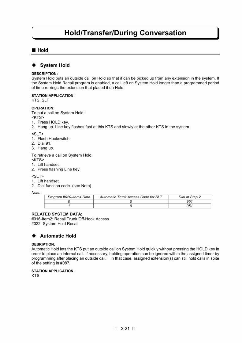
Hold/Transfer/During Conversation
3-21
!!!! Hold
" System Hold
DESCRIPTION:System Hold puts an outside call on Hold so that it can be picked up from any extension in the system. Ifthe System Hold Recall program is enabled, a call left on System Hold longer than a programmed periodof time re-rings the extension that placed it on Hold.
STATION APPLICATION:KTS, SLT
OPERATION:To put a call on System Hold:<KTS>1. Press HOLD key.2. Hang up. Line key flashes fast at this KTS and slowly at the other KTS in the system.
<SLT>1. Flash Hookswitch.2. Dial 91.3. Hang up.
To retrieve a call on System Hold:<KTS>1. Lift handset.2. Press flashing Line key.
<SLT>1. Lift handset.2. Dial function code. (see Note)
Note:Program #020-Item4 Data Automatic Trunk Access Code for SLT Dial at Step 2
0 0 9511 9 051
RELATED SYSTEM DATA:#016-Item2: Recall Trunk Off-Hook Access#022: System Hold Recall
" Automatic Hold
DESRIPTION:Automatic Hold lets the KTS put an outside call on System Hold quickly without pressing the HOLD key inorder to place an internal call. If necessary, holding operation can be ignored within the assigned timer byprogramming after placing an outside call. In that case, assigned extension(s) can still hold calls in spiteof the setting in #087.
STATION APPLICATION:KTS

Hold/Transfer/During Conversation
3-22
OPERATION:To put an outside call on System Hold using Automatic Hold:1. Press the ICM key to place an extension call. The call in progress is automatically put on Hold.
RELATED SYSTEM DATA:#077: Extension Assignment 6#087: Hold Disable Timer
" Exclusive Hold
DESCRIPTION:Exclusive Hold puts an outside call on Hold at an extension so that it can only be picked up from thatextension. If not picked up within a programmed interval of time, a call on Exclusive Hold recall (re-rings)the extension that placed it on Hold. On KTS, if the recall is not answered, the call reverts to System Holdand can be picked up from any extension. On SLT, if the recall is not answered, the call reverts toextension No.10 (or attendant extension of each tenant), or cut-off.
STATION APPLICATION:KTS, SLT
OPERATION:To put an outside call on Exclusive Hold:<KTS>1. Press HOLD key twice.2. Hang up. Line key flashes fast. At all other KTS, the Line key is steadily lit (busy).
<SLT>1. Flash Hookswitch.2. Dial 92.3. Hang up.
To retrieve a call on Exclusive Hold:<KTS>1. Lift handset.2. Press flashing Line key.
<SLT>1. Lift handset.2. Dial function code. (see Note)
Note:Program #020-Item4 Data Automatic Trunk Access Code for SLT Dial at Step 2
0 0 9511 9 051
RELATED SYSTEM DATA:#015-Item4: Exclusive Hold#019-Item5: SLT Exclusive Hold Release#021: Exclusive Hold Recall
!!!! Music On Hold
DESCRIPTION:Music On Hold sends synthesized music to an outside party on System or Exclusive Hold. The systemprovides two kind of synthesized melody.
STATION APPLICATION:KTS, SLT
Hold/Transfer/During Conversation
3-23
OPERATION:Not applicable.
RELATED SYSTEM DATA:Not applicable.
!!!! External Music On Hold
DESCRIPTION:An external MOH music source (e.g., radio, tape player) can be used for MOH instead of internalsynthesized melody.
STATION APPLICATION:KTS, SLT
OPERATION:Not applicable.
RELATED SYSTEM DATA:#056: Relay Contact Assignment
!!!! Transfer
" Unannounced Transfer
DESCRIPTION:Unannounced Transfer lets an extension user transfer (send) a call directly to another extension - that is,without first notifying the receiving extension of the call. An Unannounced Transfer rings the receivingextension. If the receiving extension does not answer within the Unannounced Transfer Recall interval,the call recalls (re-rings) the transferring extension.
STATION APPLICATION:KTS, SLT
OPERATION:To make an Unannounced Transfer:<KTS>1. Press ICM key, then dial extension number.2. Press TRFR key or hang up. (according to #080-Item5)
<SLT>1. Flash Hookswitch.2. Dial extension number.3. Hang up.
To receive an Unannounced Transfer:<KTS>1. Lift handset. If Recall Trunk Off-Hook Access is programmed, this single step answers the call.2. Press flashing Line key (key flashes green).
<SLT>1. Lift handset.
Hold/Transfer/During Conversation
3-24
RELATED SYSTEM DATA:#016-Item2: Recall Trunk Off-Hook Access#023: Unannounced Transfer Recall#080-Item5: On-Hook Transfer
" Announced Transfer
DESCRIPTION:Announced Transfer automatically puts the call on System Hold so that the transferring extension cannotify the receiving extension before actually sending the call. To receive an Announced Transfer,receiving extension just wait on the line to be automatically connected to the transferred caller. Both thetransferring and receiving extensions receive a "fast flash" Hold indication, making the call easy toidentify, while all other KTSs see a "slow flash." If the call is not sent within the Announced TransferRecall interval, the call then shows a "slow flash" at the receiving extension, and re-rings the transferringextension.
STATION APPLICATION:KTS, SLT
OPERATION:To make an Announced Transfer:<KTS>1. Press ICM key, then dial extension number.2. Announce the call.3. Press TRFR key or hang up. (according to #080-Item5)
<SLT>1. Flash Hookswitch.2. Dial extension number.3. Announce the call.4. Hang up.
To receive an Announced Transfer:<KTS>1. Lift handset when notified of the call.2. Just wait on the line to be automatically connected to the transferred caller.
<SLT>1. Lift handset to answer a call.2. Just wait on the line to be automatically connected to the transferred caller.
RELATED SYSTEM DATA:#024: Announced Transfer Recall#080-Item5: On-Hook Transfer

Hold/Transfer/During Conversation
3-25
" Attendant Reverting
DESCRIPTION:When hold transfer is failed because the destination telephone did not answer and returned back tooriginating telephone, then the originating telephone did not answer, the next action is selected bysystem data (Program #019-Item5) as follows:1) The call will be cut off by pre-set timer (Program #029) is over.2) The call will be transferred to the Attendant Telephone.
Attendant Telephone: Extension No.10 or operator station of each tenant
This timer (Program #029) will be activated as below condition.1. Put an outside call on System Hold.2. Announced Transfer Recall timer is released.3. Unannounced Transfer Recall timer is released.4. Exclusive Hold Recall timer is released.
STATION APPLICATION:KTS, SLT
OPERATION:Not applicable.
RELATED SYSTEM DATA:#008-Item4: Tenant Group#019-Item5: SLT Exclusive Hold Release/Attendant Revert Timeout#029: Attendant Reverting#052: Tenant Feature#054: Tenant Attendant
" Recall Trunk Display
DESCRIPTION:Executive telephone can be set to the Recall Trunk Display Mode. When Hold Recall tone is heard, thetelephone will display the held Trunk line and the telephone number.
STATION APPLICATION:KTS with LCD
OPERATION:To set/reset:1. Press SPK key.2. Press ICM key. (See Note)3. Press OPAC key.4. Press CHECK key.
Note : If Program #075-Item4 is 0 (No tone), skip Step 2.
RELATED SYSTEM DATA:Not applicable.

Hold/Transfer/During Conversation
3-26
!!!! Park Hold
DESCRIPTION:This feature permits transferring of a call placed on temporary hold on a Park Hold key. It is used totransfer an outside call to KTSs that do not appear under a key in order to answer a call on that line. ParkHold key can be assigned on Line keys. The system has four Park Hold groups. An extension can beassigned to only one Park Hold group. A line group can contain any number of lines. An extension usercan answer a call placed on Park Hold only if the extension is in the same Park Hold group. If the lineseized by Loop key is put on Park Hold, the Loop key’s LED goes off, and an idle Trunk line can beseized by pressing the Loop key.
STATION APPLICATION:KTS
OPERATION:To place a call on Park Hold:
- While on an outside call.1. Press Park Hold key.
To answer a call on Park Hold:1. Lift handset.2. Press Park Hold key.
To answer a call on I-Hold (the call placed on System Hold or Exclusive Hold by the extension user itself)in case the line which does not appear under Line key is held:1. Lift handset.2. Press ICM key. (See Note)3. Press OPAC key.4. Dial 3.
Note : If Program #075-Item4 is 0 (No tone), skip Step 2.
RELATED SYSTEM DATA:#008-Item5: Park Hold Group#055: Park Hold Key Assignment
!!!! Conference
" Add-On Conference
DESCRIPTION:Add-On Conference lets an extension user establish an outside call and then add up to five other insideparties to the conversation. If Multi-Line Conference is enabled in programming, a second outside callcan be added to the conversation.
STATION APPLICATION:KTS, SLT

Hold/Transfer/During Conversation
3-27
OPERATION:
<Method 1>To establish an outside call:<KTS>1. Establish an outside call.2. Press CONF key.3. Press ICM key.4. Dial extension number of invited inside party. This party must answer using the handset.5. Press CONF. Conference established. To add more inside parties, repeat steps 2-5.
<SLT>1. Establish an outside call.2. Flash Hookswitch.3. Dial 93.4. Dial extension number of invited inside party.5. Flash Hookswitch.
Conference established. To add more inside parties, repeat steps 2-5.
<KTS/SLT>To join an Add-On Conference when invited:1. Lift handset.
<Method 2>To establish an Add-On Conference:<KTS only>1. Establish outside call.2. Press CONF key.3. Press ICM key and call the other telephones by paging and tell the Line key number. The called
parties must press the Line key to join.4. Press CONF key.
To join an Add-On Conference when invited:1. Lift handset.2. Press Line key.
RELATED SYSTEM DATA:#016-Item4: Add-On Conference Setup Mode
" Multi-Line Conference
DESCRIPTION:Multi-Line Conference allows an extension user to establish an outside call and then add another outsideparty to the conversation.- If desired, the user can add five more inside parties to the conversation (for a total of six inside and two
outside parties).- Another extension user can join (break into) the Conference using Break-In as long as the total number
of inside parties does not exceed six.
STATION APPLICATION:KTS, SLT
OPERATION:To establish a Multi-Line Conference:<KTS>1. Establish first outside call.2. Press CONF key. Call is put on Hold.3. Establish second outside call.4. Press CONF key. Conference is established.
Hold/Transfer/During Conversation
3-28
<SLT>1. Establish first outside call.2. Flash Hookswitch.3. Dial 94 and press 2-digit line No.4. Establish second outside call.5. Flash Hookswitch. Conference established.
To add inside parties to a Multi-Line Conference:<KTS>1. Press CONF key. Conference is put on Hold.2. Press ICM key. Hear dial tone.3. Dial extension number. Called party must lift the handset to answer.4. Press CONF key. Conference is re-established. To add more inside parties, repeat steps 1-4.
<SLT>1. Establish outside call.2. Flash Hookswitch.3. Dial 93.4. Dial extension number of invited inside party. Called party must lift the handset to answer.5. Flash Hookswitch. Conference established. To add more inside parties, repeat steps 2-5.
RELATED SYSTEM DATA:#016-Item5: Multi-Line Conference
" Internal Conference
DESCRIPTION:Internal Conference allows a multiple-party Intercom conversation. An extension user can establish anInternal Conference with up to five other extension users (i.e., for a total of six internal parties).
STATION APPLICATION:KTS, SLT
OPERATION:To establish an Internal Conference:<KTS>1. Establish Intercom call. The called party must answer using the handset.2. Press CONF key. Hear dial tone.3. Dial extension number of another internal party. The called party must answer using the handset.4. Once the called party answers, Conference is established. To add more internal parties, repeat steps
2-4.
Note : If Manual Mode (Program #080-Item4 = 0) is assigned, Conference initiator must press CONFkey after the called party answers to establish an internal conference.
<SLT>1. Establish Intercom call. The called party must answer using the handset.2. Flash Hookswitch. Hear dial tone.3. Dial extension No. of another internal party. The called party must answer using the handset.4. Once the called party answers, Conference is established. To add more internal parties, repeat steps
2-4.
Note : If Manual Mode (Program #080-Item4 = 0) is assigned, Conference initiator must flashHookswitch after the called party answers to establish an internal conference.
To join an Internal Conference when invited:<KTS, SLT>1. Lift handset and wait.
RELATED SYSTEM DATA:#080-Item4: Internal Conference Mode

Hold/Transfer/During Conversation
3-29
!!!! Long Conversation Warning (Three Minutes)
DESCRIPTION:Long Conversation Warning is a signal reminder that sounds every three minutes while an extension ison an outgoing outside call. The signal reminder is a series of three short tones that sound over thespeaker of the phone.
STATION APPLICATION:KTS
OPERATION:Not applicable.
RELATED SYSTEM DATA:#018-Item1: Three Minutes Warning Tone
!!!! Long Conversation Cut-Off
DESCRIPTION:A conversation on an external call (only Outgoing Call) can be forcibly terminated by the system after apre-programmed period has lapsed. Before terminating the call, a warning tone (400 Hz continuous tone)will be sent to the caller within a pre-programmed period. This feature is enabled or disabled on anextension basis.This feature permits the restriction of long conversations on certain extensions.
STATION APPLICATION:KTS, SLT
OPERATION:Not applicable.Note 1: “Conversation Timer” (Program #082-1) will be activated even if the assigned extension places an outgoing
call then transfers that Trunk line to another extension. (Conversation Timer will also be activated even iftransferred extension is set to 0 by Program #075-Item5.
Note 2: In the event of Multi-line Conference being established by the assigned extension, only outgoing Trunk linewill be forcibly terminated after the pre-programmed period has lapsed. The conversation betweenIncoming Trunk line and the assigned extension will still be maintained.
RELATED SYSTEM DATA:#075-Item5: Long Conversation Cutoff#082: Long Conversation Cutoff Timer
!!!! Break-In
DESCRIPTION:Break-In lets an extension user override the system's privacy feature - a key telephone user can breakinto an outside call at another extension, including a call on a Private Line. The intrusion may or may notbe preceded by a warning tone, depending on programming (Program #004-Item1), and the warningtone comes over the speaker of both extensions. A warning intrusion tone can be sent in every 2seconds by programming (Program #078-Item3).
STATION APPLICATION:KTS
OPERATION:1. Lift handset or press SPK key.2. Press steadily lit Line key. This breaks into the telephone conversation on that line.

Hold/Transfer/During Conversation
3-30
RELATED SYSTEM DATA:#004-Item1: Break-In#078-Item3: Break In Warning Tone

Other Trunk Features
3-31
!!!! PBX Compatibility
DESCRIPTION:The system can accommodate Central Office (CO) lines or lines from a Private Branch Exchange (PBX)already installed at the customer site. The lines are similar in the way incoming calls are answered, butdifferent in the way outgoing calls are placed - an outgoing call on a PBX line requires an access codebefore dialing, while an outgoing call on a CO line does not. System/telephone features are available toboth types of lines, and PBX features are available to the PBX lines via the Flash feature (see Flash).
PBX Night ModeIf any of lines are from a PBX, and when the PBX is set in night mode, the lines connected to PBX areswitched to real CO lines, provision is made for such things as abbreviated dialing. If you have a PBX COAccess Code programmed with a dialed number for abbreviated dialing, such as "9 pause81448111111", when your System is in the night mode the 9 and the pause will be omitted when usingthe abbreviated dialing in night mode.
STATION APPLICATION:KTS, SLT
OPERATION:Not applicable.
RELATED SYSTEM DATA:#001-Item1: Line Type#026: Flash Timer#038: PBX CO Access Codes#001-Item4: PBX Night Mode#015-Item2: Night Service
!!!! Dial Mode (Tone/Pulse) Selection
DESCRIPTION:Allows the user to select the dialing mode (tone or pulse) of each CO/PBX line.- TONE(DTMF)Dial Mode
The dial signal from the extension (with tone or pulse dial mode) will be converted to TONE. TONEwill then be transmitted to the CO/PBX.
- PULSE Dial ModeThe dial signal from the extension (with tone or pulse dial mode) will be converted to PULSE. PULSEwill then be transmitted to the CO/PBX.
The assigned Dial Mode must conform to the Dial Mode of the CO lines ordered from the TELECOM orthe Dial Mode of the PBX.
STATION APPLICATION:KTS, SLT
OPERATION:Not applicable.
RELATED SYSTEM DATA:#001-Item2: Dial Mode#017-Item1: Dial Pulse Sender Speed#017-Item2: Make/Break Ratio#017-Item3: DTMF Minimum Pause Time

Other Trunk Features
3-32
!!!! Private Line
DESCRIPTION:The Private Line feature allows an incoming and/or outgoing outside line to be assigned to only oneextension for exclusive use by that extension. Any outside line can be designated as a Private Line. Allfeatures involving outside lines apply to Private Lines as well - for example, calls are placed andanswered on a Private Line as they are on any other line.1) Private Line is assigned to an extension as follows:
- A line group must be formed that contains only the Private Line. For example, if line 3 is to be usedas a Private Line, line group XX must have the following entry in Program #002: 002-XX-03-03 (i.e.,line 03 is the lowest and highest numbered line in the group).
- The line group must be assigned to only one extension in Program #006 and/or Program #007 foroutgoing and/or incoming access, respectively.
2) An extension programmed for the Break-In feature can break into a call on a Private Line.
STATION APPLICATION:KTS, SLT
OPERATION:Not applicable.
RELATED SYSTEM DATA:#002: Line Group#006: Outgoing Trunk Access#007: Incoming Trunk Access/Audible
!!!! Tenant Service
DESCRIPTION:Tenant Service allows two or more independent businesses to share the system. Each tenant can beassigned incoming and/or outgoing outside lines dedicated for its own use. Some features (Extensioncalls, Paging calls, Abbreviated Dialing, Attendant Reverting) can be partitioned among the tenants.Night Transfer can be independently used by each tenant if a "1" is entered in Program #015-Item2.
STATION APPLICATION:KTS, SLT
OPERATION:Not applicable.
RELATED SYSTEM DATA:#002: Line Group Assignment#006: Outgoing Trunk Access#007: Incoming Trunk Access/Audible#008-Item4: Tenant Group#015-Item5: Night Service#052: Tenant Feature#053: Tenant Abbreviated Dial#054: Tenant Attendant

Other Trunk Features
3-33
!!!! Unsupervised Conference
DESCRIPTION:Unsupervised Conference allows an extension user to establish a Conference with two outside parties,then hang up, leaving the outside parties connected. The system can accommodate up to fourUnsupervised Conference at a time, and each Unsupervised Conference must be assigned anunused extension port in Unsupervised Conference Port Assignment (program #005), and Multi-Line Conference must be enabled in programming.
STATION APPLICATION:KTS
OPERATION:To establish an Unsupervised Conference:1. Establish first outside call.2. Press CONF key. The call is put on Hold.3. Establish second outside call.4. Press CONF key.
- Three-party Conference is established.5. Press CONF key.
- Both outside parties are put on Hold.6. Hang up.
- Unsupervised Conference is established.
To later join an Unsupervised Conference:1. Lift handset.2. Press either Line key of the Conference.
To terminate:1. Establish Three-party Conference.2. Hang up.
- Both outside lines become idle.
Note: When both outside parties finish the call, unsupervised conference must be manually terminated bythe telephone which sets up the call.
RELATED SYSTEM DATA:#005: Unsupervised Conference Port Assignment#016-Item5: Multi-Line Conference#080-Item7:Unsupervised Conference Extension
!!!! Call Timer
DESCRIPTION:Call Timer is an automatic stopwatch feature that timer outgoing outside calls on Display phones. Thedisplay changes to a stopwatch at the programmed Call Duration Start Time and the timing stops whenthe extension user hangs up. The display shows the duration of the call for approximately eight seconds,then changes to the date and time.
STATION APPLICATION:KTS with LCD
OPERATION:Not applicable.
RELATED SYSTEM DATA:#025: Call Duration Start Time

Other Trunk Features
3-34
!!!! DISA (Trunk-to-Trunk)
DESCRIPTION:Direct Inward System Access (DISA) lets someone outside the system call in on a DISA line andplace a call on a system line, bypassing the system operator. A security code is required to place anoutside call (Trunk-to-Trunk), and the Toll Restriction Class assigned to a security code determinesthe type of calls that can be placed. The DISA caller must use a DTMF telephone. The lines can bedisconnected automatically when the assigned Trunk-to-Trunk Cut-Off Timer elapses and a userdoes not dial “1” within 10 seconds.
When Trunk Line is assigned as DISA Line in Program #003-Item1, DISA port can be allocated to anyone of DISA line which must be programmed in Program #008-Item1 with data 1".
Voice Announce Unit (VAU) (Optional Item) can be used to the system as voice announce device forDISA Line. VAU unit provides guidance messages by user-recorded voice on DISA feature (for outsideparty).
STATION APPLICATION:System
OPERATION:
To use DISA to place a call on a system line (Trunk-to-Trunk):1. Call the DISA line. The system answers with dial tone or voice recorded message.2. Dial #.3. Dial DISA security code. Receive confirmation tone.4. Dial Queue Group number (1-6) for desired line or dial 9, then two-digit line number. If busy tone is
heard, use either procedure below to disconnect.5. Dial telephone number including PBX Access Code if required.6. Dial #. The call rings through.
To hang up the outside call and reuse the DISA line:1. Dial # and ∗ . Hear dial tone.2. Dial #.3. Dial DISA security code. Receive confirmation tone.4. Dial Queue Group number (1-6) for desired line or dial 9, then two-digit line number. If busy tone is
heard, use either procedure below to disconnect.5. Dial telephone number including PBX Access Code if required.6. Dial #. The call rings through.
To disconnect both the DISA line and the system line:(When Polarity Reverse Detection is not available)1. Dial #, #.Note: This procedure must be used before hanging up. If not, the Trunk-to-Trunk condition continues until the
assigned Trunk-to-Trunk Cut-Off Timer elapses.
To disconnect both the DISA line and the system line:(When Polarity Reverse Detection is available)1. Hang up.
To continue conversation when Trunk-to-Trunk cut-off warning tone is heard:1. Dial 1.
Refer to the "DISA Operation Flowchart" in this Manual (P. 3-100)
RELATED SYSTEM DATA:#003-Item1: DISA Line#003-Item2: DISA Line Access#008-Item1:Instrument Type#030: Voice Recorded Message Time

Other Trunk Features
3-35
#031: Trunk-to-Trunk Cut-Off Timer Assignment#046-Item1: DISA Security Codes#046-Item2: DISA Security Code Extension Assignment#046-Item3: DISA Toll Restriction Class#064-Item4: LED Indication for DISA Incoming Call#066: DISA Timers
!!!! Second Trunk Access Code for SLT
DESCRIPTION:When your system is installed behind a PBX, or it accommodates both Central Office(CO) lines andPrivate Branch Exchange (PBX) lines, simply use a single-digit Second Trunk Access Code (dial 7) toseize a first available PBX line.
STATION APPLICATION:SLT
OPERATION:
To make a PBX extension call:<SLT>1. Lift handset.2. Dial 7.3. Dial a PBX extension Number.
To make a PBX outside call:1. Lift handset.2. Dial 7.3. Dial your PBX Trunk Access Code (e.g.9).4. Dial a telephone number.
RELATED SYSTEM DATA:#001-Item1: Line type

Intercom Outgoing Call
3-36
!!!! Intercom Link Increase
DESCRIPTION:There is 5 intercom links in the TX-Z2 824 System. One link is reserved if Background Music is used inTX-Z2 824 system. Intercom Link Increase allows unused Trunk line circuits to be used as Intercomlinks, providing increased Intercom calling capabilities. The Intercom Hold/Conference feature is disabledwhen Intercom links are increased. Nitsuko Voice Mail System (NVM Series) can not be used if intercomlink is increased.
STATION APPLICATION:System
OPERATION:Not applicable.
RELATED SYSTEM DATA:#045: Intercom Link Increase
!!!! Intercom Call
DESCRIPTION:Intercom Call allows extension-to-extension conversation. The system can be programmed for one oftwo Intercom Signaling modes: ringing or voice announce. When voice announce is programmed, anIntercom call signals the called extension with a beep (not ringing). After the beep sounds, the caller canmake a voice announcement over the speaker of the called extension.Regardless of the signaling mode programmed, an extension user can change it on a per call basis. Forexample, a ringing Intercom call can be changed to a voice announced call by dialing a code.
STATION APPLICATION:KTS, SLT
OPERATION:To place an Intercom call:<KTS>1. Lift handset or press SPK key. (See Note 1)2. Dial extension number.To convert a ringing call into a voice announced call, or vice versa, dial 1.
<SLT>1. Lift handset.2. Dial extension number.To convert a ringing call into a voice announced call, or vice versa, dial 1.
Note 1: If Program #075-Item4 is 0 (No tone), press ICM key after Step 1 to seize Intercom.Note 2: Call Monitor, Speakerphone and Single Step Access provide ways to place Intercom Calls without lifting the
handset.
RELATED SYSTEM DATA:#019-Item2: Intercom Call Type#075-Item4: Key Telephone Off-Hook Mode Selection

Intercom Outgoing Call
3-37
!!!! Direct Station Selection
DESCRIPTION:Direct Station Selection (DSS) provides an extension user with one-button access to other extensions inthe system. Each of the ten One-Touch keys on a key telephone can be programmed to call a particularextension. The One-Touch keys can also be programmed to access any Page Zone (see Paging) orDoorphone using the steps below.
STATION APPLICATION:KTS
OPERATION:To program a One-Touch key for DSS:1. Lift handset.2. Press ICM key. (See Note)3. Press DC.4. Dial #.5. Press One-Touch key.6. Dial extension number.
orto program a Page Zone, dial 80-85.to program a Doorphone, dial 88 or 89.
7. To program more keys, repeat steps 3-6.8. Hang up.
Note : If Program #75-D is 0 (No tone), skip Step 2.
To use a DSS key:1. Lift handset. If Single Step Access is programmed and the phone is equipped with a Speakerphone,
this step can be skipped.2. Press One-Touch key set as DSS key.
To hold and transfer a Trunk call using a DSS key:- Make conversation with an outside party.
1. Press a desired One-Touch key set as DSS key.- The Trunk line will automatically be held, then intercom call will be established.
2. Make announcement (if desired).3. Press TRFR key or hang up to transfer.
To display the number programmed under a DSS/One-Touch key:- Do not lift handset.
1. Press CHECK key.2. Press ICM key.3. Press One-Touch key.
- Key number displays, then stored number.4. Press CLEAR to return to normal display.
On TX-Z2 824 System, One-Touch Key No.1 to No.9 are initially programmed as DSS for ExtensionNo.10 to No.18, One-Touch Key No.10 for All Call Paging (80).
RELATED SYSTEM DATA:Not applicable.
Intercom Outgoing Call
3-38
!!!! Intercom Off-Hook Signaling
DESCRIPTION:Intercom Off-Hook Signaling lets an extension user send a signal to a busy extension, then wait for areplay. The signal is one short burst of tones, which comes over the speaker of the busy extension. Inaddition, the ICM key at the busy extension flashes. The busy extension user can choose not to reply tothe signal if it is inconvenient to do so.An extension can be programmed to send Intercom Off-Hook Signaling in one of two ways: manually orautomatically. The manual-type requires the user to dial a code to send the signal, while the automatic-type sends the signal automatically any time a user calls a busy extension. Intercom Off-Hook signalingcannot be sent to a busy extension when it is using Handsfree Answerback. Single Line Telephones(SLT) can send and receive the signals. Extensions programmed for Automatic Intercom Off-HookSignaling cannot use the Camp-On or Callback features.
STATION APPLICATION:KTS, SLT
OPERATION:To manually send Intercom Off-Hook Signaling:<KTS/SLT>1. Place Intercom call. Hear busy tone.2. Dial 1. Hear one short burst of tones.3. Wait for a reply. To send more tones, dial 1 again.
To use automatic Intercom Off-Hook Signaling:<KTS/SLT>1. Place Intercom call. When the called extension is busy, one short burst of tones is heard instead of
busy tone.2. Wait for a reply. To manually send more tones, dial 1.
To answer an Intercom Off-Hook Signaling:<KTS>1. Press flashing ICM. This answers the waiting call and puts an outside call in progress on Hold. This
step will, however, terminate an Intercom call in progress; Intercom calls cannot be put on Hold.<SLT>1. Flash Hookswitch (On-hook → Off-Hook). This answers the waiting call and terminates an Intercom
call in progress.
RELATED SYSTEM DATA:#004-Item3: Intercom Off-Hook Signaling
!!!! Group Hunt
DESCRIPTION:Group Hunt searches for an idle extension among all the extensions in a particular Hunting Group.Extensions are assigned to Hunting Groups in programming - for example, all the extensions in a salesdepartment might be assigned to Hunting Group 4. When an extension user dial a Hunting Groupnumber, the Group Hunt feature automatically calls the first idle one it finds. When all extensions in aHunting Group are busy, a user receives busy tone and can activate Callback or Camp-On. Thesefeatures automatically connect the user to the first extension programmed into that group as soon as itbecomes available. When the called extension does not answer in the preprogrammed time, the systemautomatically calls the next idle extension in the same Hunting Group according to the order in theHunting Group. The caller can also call the next idle extension by manual operation. The extension tobe searched first in the Hunting Group can be fixed or circulated (Program #080-Item2). When allextensions in the same Hunting Group are searched and no extension answers, Group Hunt is canceled.

Intercom Outgoing Call
3-39
STATION APPLICATION:KTS, SLT
OPERATION:<KTS>1. Lift handset. (See Note 1)2. Dial #.
3. Dial Hunting Group No. (0 – 7)- The first idle extension is called. If the extension does not answer in the preprogrammed time, the system calls the next idle extension, or the caller can dial # to call next idle extension.
Note 1 :If Program #075-Item4 is 0 (No tone), press ICM key after Step 1 to seize Intercom.Note 2: SLT can not use this feature.Note 3: When Program #080-Item2 = 1, the extension of the first order no. is called after the extension of the last
order no. is called first. If the Hunting Group calling timer expires, Group Hunt is used again, or Step Call(pressing #) is used.
RELATED SYSTEM DATA:#011: Hunting Groups#084: Hunting Group Calling Timer#080-Item2: Group Hunt Mode
!!!! Step Calling
DESCRIPTION:When an extension user makes an Intercom call and receives a busy signal or no answer, Step Callinglets the user call the other extensions, in ascending order, by just dialing a code. For example, ifextension 12 is busy, Step Calling tries extension 13. If there is no answer at extension 13, Step Callingtries extension 14, and so on. Step Calling is canceled if it reaches an extension that is not installed.
STATION APPLICATION:KTS, SLT
OPERATION:1. Place Intercom call.
- Receive busy tone or no answer.2. Dial #.
- Next extension is automatically called. To call the next extension, dial # again.
RELATED SYSTEM DATA:Not applicable.

Intercom Outgoing Call
3-40
!!!! Camp-On (Callback)
DESCRIPTION:Instead of hanging up after calling a busy extension, Camp-On lets an extension user dial a code andwait off-hook until the extension becomes available. As soon as the extension becomes free, the callautomatically goes through. Or, if the extension user hangs up after dialing the code, Callbackautomatically redials a busy extension. When the busy extension becomes free, Callback signals (rings)the extension that activated it. When the Callback signal is answered, an Intercom call is automaticallyplaced to the previously busy extension. Calls can be placed while waiting for the Callback signal, andCallback can be activated for more than one busy extension at a time. Camp-On/Callback cannot beactivated by an extension that is programmed for Automatic Intercom Off-Hook Signaling (Program#004-Item3). Camp-On/Callback can also be activated when a user calls a busy Hunting Group (seeGroup Hunt).
STATION APPLICATION:KTS, SLT
OPERATION:To activate Camp-On:1. Place Intercom call. Hear busy tone.2. Dial ∗ . Busy tone stops.3. Do not hang up.4. Wait for the call to go through. Ringing is heard as soon as the extension becomes free.
To activate Callback:1. Place Intercom call. Hear busy tone.2. Dial ∗ . Busy tone stops.3. Hang up.
To answer the Callback signal:- The signal sounds like an Intercom ring, but the ICM key does not flash.
1. Lift handset. Extension is called.
To cancel Callback:1. Lift handset to cancel Callback before receiving the Callback signal.2. Hang up.
RELATED SYSTEM DATA:Not applicable.
!!!! Message Waiting
DESCRIPTION:When an extension user makes an Intercom call and receives a busy signal or no answer, MessageWaiting lets this user leave a visual indication (flashing MW/Indicator light) at the busy/unattended phonerequesting a return call. An extension user can leave Message Waiting indications at several differentextensions.
STATION APPLICATION:KTS, SLT
OPERATION:To leave a Message Waiting:<KTS/SLT>1. Place Intercom call. Busy or no answer.2. Dial 0. MW/Indicator flashes intermittently as confirmation (KTS).

Intercom Outgoing Call
3-41
3. Hang up.
To call the extension that left a Message Waiting indication:<KTS>1. Seize Intercom.2. Dial ∗ .
The extension is called.3. To call the next extension that left a Message Waiting indication, dial ∗ again.
<SLT>1. Lift handset. (Hear Message Waiting dial tone)2. Dial ∗ .
To cancel all Message Waiting indications:<KTS>1. Lift handset.2. Press ICM key. (See Note 2)3. Dial ∗ , 0, ∗ .
4. Hang up.
<SLT>1. Lift handset.2. Dial function code. (see Note 3)
To cancel an individual Message Waiting:<KTS only>1. Lift handset.2. Press ICM key. (See Note 2)3. Dial ∗ , destination extension number, ∗ .
4. Hang up.
<KTS with LCD only>- Do not lift handset -
1. Press OPAC key2. Press CLEAR key. (see Note 4)
To display the extension number that left a Message Waiting:<KTS with LCD>
- Do not lift handset.1. Press CHECK key.2. Dial ∗ . Extension number is displayed.3. Press Hold key to clear the Message Waiting Indication.4. Press ICM key to call back Message Waiting originating extension.5. To display the next extension number that left a Message Waiting indication, dial ∗ again.6. Press CLEAR to return to normal display.

Intercom Outgoing Call
3-42
Note 1: When SLT is set this feature, the SLT's dial tone changes from continual tone to 0.4 sec. On/0.1 sec. OFF.Note 2 :If Program #075-Item4 is 0 (No tone), skip Step 2.Note 3:
Program #020-Item4 Data Automatic Trunk Access Code for SLT Dial at Step 20 0 9591 9 059
Note 4: This operation can be available at extension which MW is set. The extension has to be only KTS with LCD.Note 5: The message waiting lamp on SLT (e.g.ST5E Message Lamp type) does not flash even if the extension was
left Message Waiting.
RELATED SYSTEM DATA:#080-Item1: Message Waiting
!!!! Paging
DESCRIPTION:Internal Paging lets an extension user make a paged announcement over the speaker of the othertelephones in the system. Any extension can make a page, but only key telephones that are assigned toan Internal Page Zone can receive a page. There are four types of Internal Paging:- Internal Zone Paging lets an extension user page all the telephones assigned to a particular Internal
Page Zone.- All Call Paging lets an extension user page all Internal Page Zones.- Meet-Me Answer/Conference Paging allows an extension user to page one or more persons, then
reserve an Intercom circuit for 30 seconds so that the paged party/parties can reply. Meet-Me Answerlets one party reply, while Meet-Me Conference lets up to five people reply and jointly converse.
The system has four zones, numbered 1-4. The system can be programmed to broadcast All Call Pagingover external speakers.
External Zone Paging allows customer-provided paging equipment (speakers, amplifiers, etc.) to beinstalled in large, noisy area (zone) so that extension user can make paged announcement to this zone.
STATION APPLICATION:KTS, SLT
OPERATION:To make a page:<KTS>1. Seize Intercom.2. Dial code.
- 80 for All Call.- 81-84 for zones 1-4.- 85 for external zone 1
3. Make announcement.4. Hang up.

Intercom Outgoing Call
3-43
<SLT>1. Lift handset2. Dial code.
- 80 for All Call.- 81-84 for zones 1-4.- 85 for external zone 1
3. Make announcement.4. Hang up.
To initiate Meet-Me Answer:<KTS>1. Seize Intercom.2. Dial code.
- 80 for All Call.- 81-84 for zones 1-4.- 85 for external zone 1
3. Page person, announce code.- 80-85
4. Dial # for Meet-Me Answer5. Do not hang up. Wait for a reply.
<SLT>1. Lift handset2. Dial code.
- 80 for All Call.- 81-84 for zones 1-4.- 85 for external zone 1
3. Page person, announce code.- 80-85
4. Dial # for Meet-Me Answer.5. Do not hang up. Wait for a reply.
To reply to Meet-Me Answer:<KTS>1. Lift handset or press SPK at a phone that received the page.2. Press ICM key. (See Note 1)3. Dial announced code.
- 80-85, or 88(same zone)

Intercom Outgoing Call
3-44
<SLT>1. Lift handset at a phone that received the page.2. Dial function code. (see Note 2)3. Dial announced code.
- 80-85, or 88(same zone)
Note 1 :If Program #075-Item4 is 0 (No tone), skip Step 2.Note 2:
Program #020-Item4 Data Automatic Trunk Access Code for SLT Dial at Step 20 0 981 9 08
To initiate Meet-Me Conference:<KTS>1. Seize ICM.2. Dial code 81-84 for zones 1-4; 80 for All Call.3. Page person, announce that pressing CONF key will join Meet-Me Conference.4. Press CONF key for Meet-Me Conference.5. Do not hang up. Wait for a reply.
To reply to Meet-Me Conference:<KTS>1. Lift handset or press SPK at a phone that received the page.2. Press ICM key. (See Note)3. Press CONF key for Meet-Me Conference.
Note : If Program #075-Item4 is 0 (No tone), skip Step 2.
RELATED SYSTEM DATA:#008-Item3: Internal Page Zone#019-item1: All Call to External Zone#020-Item2: Paging Splash Tone
!!!! Flexible Station Numbering
DESCRIPTION:Flexible Station Numbering allows any extension number, within a specific range, to be assigned to eachtelephone port in the system. Originally, extension numbers match telephone port numbers. Refer to thechart below for the range of extension numbers available to the telephone ports.
SystemPort
Available ExtensionNumbers (2 digit)
Available ExtensionNumbers (3 digit)
10-33 10-69 100-699
STATION APPLICATION:KTS, SLT
OPERATION:Not applicable.
RELATED SYSTEM DATA:#014: Station Numbering

Intercom Outgoing Call
3-45
!!!! Dual Handsfree Hotline
DESCRIPTION:Dual Handsfree Hotline allows one extension to simultaneously call two other extensions. The"secretary" extension can make a voice announced Intercom call over the speaker of both "executive"extensions. The users at the executive extensions can reply Handsfree (i.e., by just speaking toward thephone) and all three parties can converse. The simultaneous call goes through only if both executiveextensions are idle and an executive extension has not forwarded Intercom calls. In order to replyHandsfree, the microphone at an executive extension must be on. When an executive replies by liftingthe handset, the other executive is disconnected. The secretary can make a ringing Intercom call to bothexecutives; however, an executive must lift the handset to reply, which disconnects the other executive.
STATION APPLICATION:KTS
OPERATION:1. Seize Intercom at secretary extension.2. Dial either executive extension number. Both are called. If ringing is heard, the secretary can dial 1 to
convert the call into a voice announced call. If busy tone is heard, the secretary can still contact theother executive by dialing the other executive extension number after pressing ICM.
RELATED SYSTEM DATA:#010: Dual Handsfree Hotline
Intercom Incoming Call
3-46
!!!! Intercom Answer
DESCRIPTION:Intercom Answer (just lifting the handset) lets an extension user answer either signal intercom call orvoice announced intercom call in a single step.Handsfree Answerback lets a key telephone extension user answer a voice announced Intercom callwithout touching the phone.
STATION APPLICATION:KTS, SLT
OPERATION:
To answer an Intercom call:<KTS/SLT>1. Lift handset.
To answer a voice announced call using Handsfree Answerback:<KTS only>1. Speak toward the phone. The microphone must be on.
RELATED SYSTEM DATA:Not Applicable
!!!! Call Pickup
DESCRIPTION:Call Pickup provides two distinct functions: one function applies to Intercom calls and the other to outsidecalls.- Call Pickup allows the extension users to answer Intercom calls and Doorphone call. An Intercom call
that is ringing (or voice-announced) at a particular extension can be answered from any otherextension in the system.
- Call Pickup also allows the extension users to answer a Trunk incoming call, incoming call on a DISAline, and Unannounced Transfer.
In order to pick up someone else's Intercom call, an extension user must know the number of theextension that is ringing. If the ringing and answering extensions are in the same Internal Page Zone(Program #008-Item3), the # key can be used to pick up the Internal call.
STATION APPLICATION:KTS, SLT
OPERATION:To use Call Pickup to answer an Intercom call, incoming call on a DISA line Unannounced Transfer, andTrunk incoming call on a extension in own pick-up group:<KTS>1. Lift handset or press SPK key.2. Press ICM key. (See Note1)3. Dial #. If more than one extension is ringing, this code answer intercom call, unannounced transfer,
incoming call on a DISA line, and Trunk incoming call.
<SLT>1. Lift handset.2. Dial #.
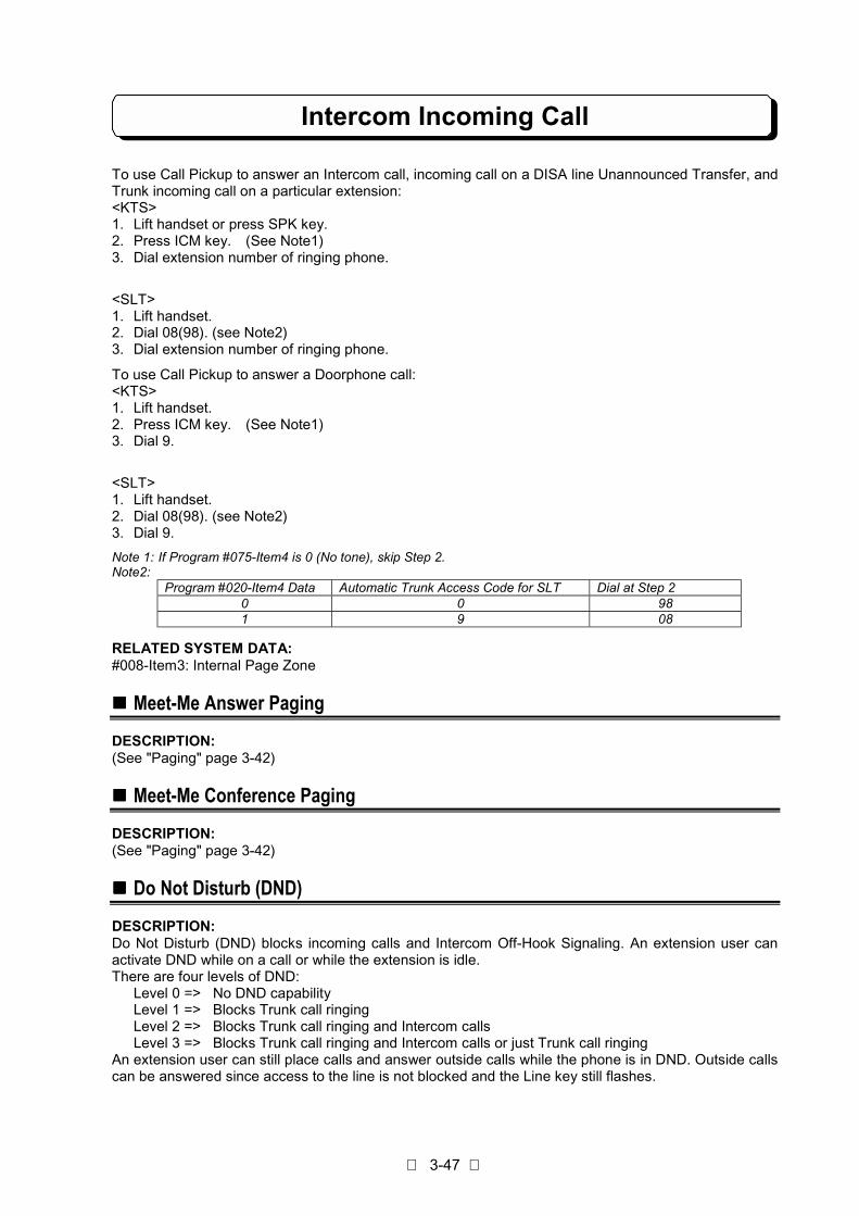
Intercom Incoming Call
3-47
To use Call Pickup to answer an Intercom call, incoming call on a DISA line Unannounced Transfer, andTrunk incoming call on a particular extension:<KTS>1. Lift handset or press SPK key.2. Press ICM key. (See Note1)3. Dial extension number of ringing phone.
<SLT>1. Lift handset.2. Dial 08(98). (see Note2)3. Dial extension number of ringing phone.
To use Call Pickup to answer a Doorphone call:<KTS>1. Lift handset.2. Press ICM key. (See Note1)3. Dial 9.
<SLT>1. Lift handset.2. Dial 08(98). (see Note2)3. Dial 9.
Note 1: If Program #075-Item4 is 0 (No tone), skip Step 2.Note2:
Program #020-Item4 Data Automatic Trunk Access Code for SLT Dial at Step 20 0 981 9 08
RELATED SYSTEM DATA:#008-Item3: Internal Page Zone
!!!! Meet-Me Answer Paging
DESCRIPTION:(See "Paging" page 3-42)
!!!! Meet-Me Conference Paging
DESCRIPTION:(See "Paging" page 3-42)
!!!! Do Not Disturb (DND)
DESCRIPTION:Do Not Disturb (DND) blocks incoming calls and Intercom Off-Hook Signaling. An extension user canactivate DND while on a call or while the extension is idle.There are four levels of DND:
Level 0 => No DND capabilityLevel 1 => Blocks Trunk call ringingLevel 2 => Blocks Trunk call ringing and Intercom callsLevel 3 => Blocks Trunk call ringing and Intercom calls or just Trunk call ringing
An extension user can still place calls and answer outside calls while the phone is in DND. Outside callscan be answered since access to the line is not blocked and the Line key still flashes.

Intercom Incoming Call
3-48
STATION APPLICATION:KTS, SLT
OPERATION:A. To activate DND while the phone is idle:
<KTS>1. For level 1: Press DND once. DND flashes.
For level 2: Press DND once. DND lights steadily.For level 3: Press DND once to block Trunk call ringing and Intercom calls.
orPress DND twice to block just Trunk call ringing. DND flashes.
<SLT>1. Lift handset.2. Dial function code. (see Note)SLT can be set for Level 2 only.
Note:Program #020-Item4 Data Automatic Trunk Access Code for SLT Dial at Step 2
0 0 9521 9 052
To cancel DND while the phone is idle:<KTS>
- Do not lift handset.1. Press DND once or twice.
- Whichever makes DND extinguish.
<SLT>1. Lift handset.2. Dial function code. (see Note)
Note:Program #020-Item4 Data Automatic Trunk Access Code for SLT Dial at Step 2
0 0 9591 9 059
B. To activate DND while on a call:<KTS>
1. For level 1: Press OPAC, DND once. DND flashes.For level 2: Press OPAC, DND once. DND lights steadily.For level 3: Press OPAC, DND once to block Trunk call ringing and Intercom calls.
orPress OPAC, DND twice to block just Trunk call ringing. DND flashes.
To cancel DND while on a call:<KTS>1. Press OPAC, DND once or twice.
- Whichever makes DND extinguish.
RELATED SYSTEM DATA:#013-Item2: Do Not Disturb
!!!! Intercom Hold
DESCRIPTION:It is possible to place an Intercom call on hold. While on hold, music is sent to the held party. UnlikeTrunk line hold, when an ICM call is held, no other action can be taken by the holding party. Only thehold-originating station can re-answer this line by pressing the ICM key.

Intercom Incoming Call
3-49
STATION APPLICATION:KTS
OPERATION:To put an Intercom call on Hold:1. Press Hold. (see note)
Note: Do not hang up while an intercom call is on Hold. If you hang up the handset, your intercom call is terminated.
To retrieve an Intercom call on Hold:1. Press ICM key.
RELATED SYSTEM DATA:Not applicable.
!!!! Intercom Call Transfer
DESCRIPTION:Intercom calls may be transferred to any extension manually.There are two methods of transferring Intercom calls.
STATION APPLICATION:KTS, SLT
OPERATION:<KTS>A. To make an Intercom Call Transfer using Intercom Hold:
1. Intercom call between A and B.2. Press HOLD key to put B on Hold.3. Extension C dials extension number of A.
.- If extension C is SLT, dial access code 08 or 98 then dial extension number of A. (See Note)
4. Intercom call between B and C is established.
Note:Program #020-Item4 Data Automatic Trunk Access Code for SLT Dial at Step 3
0 0 981 9 08
<KTS, SLT>B. To make an Intercom Call Transfer using Internal Conference (See Conference on Page 3-26 )
1. Intercom call between A and B.2. Establish an Internal Conference with C.3. Extension A hang up.
RELATED SYSTEM DATA:Not applicable.
!!!! Call Forward
DESCRIPTION:(See "Call Forward" page 3-16)
!!!! Follow Me
DESCRIPTION:(See "Follow Me" page 3-18)

Intercom Incoming Call
3-50
!!!! Executive DND
DESCRIPTION:(See "Executive DND" page 3-19)

Other Intercom Features
3-51
!!!! BGM
DESCRIPTION:Background Music (BGM), from a customer-provided music source such as radio, can be broadcast overthe speakers of the KTS. BGM plays while an extension is not in use. When Program #049 is enabled,BGM can also be broadcast over speakers in the external page zones.
STATION APPLICATION:KTS
OPERATION:To turn BGM on or off while an extension is not in use:
- Do not lift handset.1. Press #.
RELATED SYSTEM DATA:#049: External Zone BGM#056: Relay Contact Assignment#064-Item6: BGM Assignment
!!!! External Paging
DESCRIPTION:External Page Output allows incoming Trunk audible, BGM from an external source to be broadcast overspeaker that is installed in the external page zone.
STATION APPLICATION:External Speaker
OPERATION:Not applicable.
RELATED SYSTEM DATA:#002: Line Group Assignment#049: External Zone BGM#050: External Zone Trunk Audible
!!!! Doorphone
DESCRIPTION:A Doorphone, usually placed next to an entrance door, is a combination of doorbell and Intercom. Whensomeone presses the CALL button on the Doorphone, chime tones are sent to the designatedextensions. When an extension user answers the chimes, a two-way conversation is possible with theperson at the door. An extension user can also call a Doorphone. The system can accommodate up totwo Doorphones; both boxes can be used at the same time. Doorphone 1 sends different types of chimetones than Doorphone 2. When the chime is ringing or answered, an Intercom link is used.The extension(s) assigned in #061-Item5 shall be out of service for Doorphone facilities (not call/notanswer/not pickup Doorphone).
STATION APPLICATION:KTS, SLT
Other Intercom Features
3-52
OPERATION:To answer the chime tones from a phone that receives them:<KTS/SLT>1. Lift handset. Connection established.
To answer the chime tones from a phone that does not receive them (Call Pickup):<KTS>1. Lift handset.2. Press ICM key. (See Note1)3. Dial 9.
4. Connection established.
<SLT>1. Lift handset.2. Dial access code 08 or 98. (see Note2)3. Dial 9.
Note 1: If Program #075-Item4 is 0 (No tone), skip Step 2.Note 2:
Program #020-Item4 Data Automatic Trunk Access Code for SLT Dial at Step 20 0 981 9 08
To call a Doorphone:<KTS>1. Seize Intercom.2. Dial 88 for box 1, 89 for box 2.
<SLT>1. Lift handset.2. Dial 88 for box 1, 89 for box 2.
RELATED SYSTEM DATA:#012: Doorphone Call#020-Item1: Door Chime Tone Duration#020-Item3: Door Alert Tone#020-Item5: Existance of Doorphone Box#061-Item5: Doorphone Call/Answer
!!!! Door Lock Control
DESCRIPTION:A customer-provided Door Lock Control device can be installed with one of the Doorphones so that theextension users can lock/unlock that door using their phones. The door can be locked/unlocked while anextension user is talking to the door box. Relay Contact Assignment must be programmed for the device.Door relay can be changed to lock/unlock manually, or once the door is unlocked, automatic-lock isprovided according to the assigned timer.
STATION APPLICATION:KTS, SLT

Other Intercom Features
3-53
OPERATION:To unlock/lock the door after contacting the Doorphone:<KTS>1. Press FLASH key to unlock the door.2. Press FLASH key again to lock the door.
<SLT>1. Flash Hookswitch to unlock the door.2. Flash Hookswitch again to lock the door.
The door can be locked automatically when doorphone call is terminated. When using the automaticlock feature, skip step 2.
RELATED SYSTEM DATA:#056: Relay Contact Assignment#088: Door Relay Timer
!!!! Room Monitor
DESCRIPTION:Room Monitor lets one extension monitor (listen to) the environmental sounds in an area or roomcontaining another extension. Several extensions can monitor the same extension; however, only onemonitored extension can be assigned in a system.
STATION APPLICATION:KTS
OPERATION:To activate or cancel Room Monitor at the extension to be monitored:1. Lift handset.2. Press ICM key. (Note)3. Press OPAC.4. Press FLASH.
- MON flashes fast on TD/TXD type telephone while Room Monitor is activated.- MIC flashes fast on BTD/BTXD type telephone while Room Monitor is activated.
5. Hang up.
Note: If Program #075-Item4 is 0 (No tone), skip Step 2.
To activate or cancel Room Monitor at the monitoring extension:- Do not lift handset.
1. Press OPAC.2. Press FLASH.
- MON flashes intermittently on TD/TXD type telephone while Room Monitor is activated.- MIC flashes intermittently on BTD/BTXD type telephone while Room Monitor is activated.
This feature can be stored under the One-touch key.
RELATED SYSTEM DATA:#019-Item4: Room Monitor

Alphanumeric Display TEL Features
3-54
!!!! Multi-Language DisplayDESCRIPTION:The display information on your display key telephone is available in three languages. English, Spanish,and Portuguese are available, and the language can be selected by system programming.
STATION APPLICATION:KTS with LCD
RELATED SYSTEM DATA:#078-Item 8: Multi-Language Display
!!!! Text Message" Message Edit Mode
DESCRIPTION:TXD/BTXD type Key Telephones are equipped with a 2-line, 16-character Liquid Crystal Display (LCD).These displays are used to provide information such as: data/time, elapsed call time on outside calls,digits dialed, internal calling party number and Abbreviated Dialing entries, but can also perform sendingand receiving of messages. The one-touch keys and dial keys allows the user to create message andidentification name for each Trunk lines, extensions and abbreviated numbers. Each dial key (0-9)contains three letters or symbols. A message and a name can be up to 8 digits long, consisting ofalphanumeric characters, symbol marks and spaces.
STATION APPLICATION:KTS with LCD
OPERATION:<Pattern 1>(1st Model KTS)- Dial key (0-9): Numbers- One-touch key (1-3) with Dial key (0-9): Letters and symbols- One-touch key 4: Space- One-touch key 5: Delete a character- One-touch key 6: Delete all characters

Alphanumeric Display TEL Features
3-55
<Pattern 2>(Complied with ITU-T Rec.E.161.) (2nd Model KTS)- Dial key (0-9): Numbers- One-touch key (1-4) with Dial key (1-9): Letters and symbols- One-touch key 5: Space- One-touch key 6: Delete a character- One-touch key 7: Delete all characters
RELATED SYSTEM DATA:#061-Item1: Alphanumric Key Pad Assignment
" Selectable Display Messaging
DESCRIPTION:An extension user can select a preprogrammed Selectable Display Message for their extension. Displaytelephone callers see the selected message when they call the user's extension. Selectable DisplayMessaging provides personalized messaging. For example, an extension user could select the message"LEFT FOR THE DAY". Any display telephone user calling the extension would see the message. Otherthan displaying the message, the system puts the call through normally. See twenty-three Default SettingMessages (00-19, 47-49) below for a list of the standard message. The system has fifty SelectableDisplay Messages (00-49) and two Personal Display Messages (One-touch key No.1 and No.2) for eachextension.An extension user can add digits for date, time or phone number after messages 00, 01, 02, 12 and 13.For example, an extension user could select the message 13 "OUT UNTIL _ /_ " and then enter the dateon "_ /_ ". Callers see the original message followed by the appended date. They would then be able totell when the user was coming back to the office.The default messages are:

Alphanumeric Display TEL Features
3-56
00: CALL _ _ _ _ _ _ _01: CALL AFTER _ _:_ _02: CALL EXT. _ _03: CALL ME ASAP04: DO NOT DISTURB05: IN CONFERENCE06: IN MEETING07: LEFT FOR THE DAY08: ON BREAK09: ON VACATION10: OUT OF OFFICE11: OUT TO LUNCH12: OUT UNTIL _ _ : _ _13: OUT UNTIL _ _ / _ _14: PAGE ME15: PLEASE SEE ME16: SEE ME ASAP17: WITH A CLIENT18: WITH A PATIENT19: WITH A VISITOR47: TAKE MESSAGE48: PLEASE HOLD49: CALL BACK LATER.
STATION APPLICATION:KTS with LCD
OPERATION:To store text in One-touch key No.1 and No.2:1. Press CHECK and OPAC.2. Dial message number (00-49).3. Dial ∗ .- Use VOL. key to scroll through message then Dial ∗ to enter.4. Edit your own message by Message Edit Mode.5. Press CHECK.6. Press One-touch key No.1 or No.2 to store.7. Dial ∗ .8. Enter message number for next storing.
orPress CLEAR to finish.
To store system message (No.10 telephone only):1. Press CHECK and OPAC.2. Dial message number (00-49).3. Dial ∗ .- Use VOL. key to scroll through message then Dial ∗ to enter.4. Edit message by Message Edit Mode.5. Press CHECK.6. Dial message number to store.7. Dial ∗ .8. Dial message number for next storing.
orPress CLEAR to finish.
RELATED SYSTEM DATA:Not applicable.

Alphanumeric Display TEL Features
3-57
" Broadcasting the Message at Later Time
DESCRIPTION:Text message can be set to indicate on display telephones in hunt group at programmed time. If it is set,and time comes, the message will appear on display in 1 minute with alarm tone.
STATION APPLICATION:KTS with LCD
OPERATION:To set send-later message:1. Press CHECK and OPAC.2. Dial message number (00-49), dial ∗ . - Use VOL. key to scroll through message then Dial ∗ to enter.
orPress One-touch key No.1 or No.2 for personal message, then dial ∗ .
3. Edit message if required.4. Press ICM.5. Dial an extension number or hunt group number (00-04).6. Press ICM key to set more extension if required. (This step is only available when extension number
is dialed at step 5.)7. Dial ∗ .8. Enter the time of indication with 4 digits
(e.g. PM3:00 => 1500)9. Dial ∗ .
To cancel send-later message:1. Press CHECK key.2. Press TRFR key.
To stop the alarm tone and clear the display:1. Press CLEAR key.
RELATED SYSTEM DATA:Not applicable.
" DND Message
DESCRIPTION:DND Message send a message to a calling extension when your telephone have activated DND forIntercom calls.
STATION APPLICATION:KTS with LCD
OPERATION:To set DND message using preset messages:1. Press TRFR.2. Dial message number (00-49), dial ∗ . - Use VOL. key to scroll through message then Dial ∗ to enter.
orPress One-touch key No.1 or No.2 for personal message, then dial ∗ .- DND flashes intermittently as confirmation.
To set DND message that edited by Message Edit Mode.1. Press TRFR and FLASH.2. Edit message by Message Edit Mode.3. Press FLASH and ∗ . DND flashes intermittently as confirmation.
To cancel message on the telephone:1. Press CLEAR.

Alphanumeric Display TEL Features
3-58
To activate/cancel previous message (last time you set message for DND):1. Press TRFR and ∗ .
- When DND message is activated, DND flashes intermittently.
RELATED SYSTEM DATA:Not applicable.
" Leave Message with MW
DESCRIPTION:When an extension user makes an Intercom call to display phone and receives a busy signal or noanswer, this user leave a text message with Message Waiting (MW).
STATION APPLICATION:KTS with LCD
OPERATION:To leave a Message:1. Place Intercom call. Busy or no answer.2. Dial 0. MW/Indicator flashes intermittently as confirmation.
- Display shows "LEAVE MESSAGE ?", then you can enter a message. If you replace handset afterthis step operation, it is simple message waiting procedure.
3. Dial ∗ .4. Dial message number (00-49), dial ∗ . - Use VOL. key to scroll through message then Dial ∗ to enter.
orPress One-touch key No.1 or No.2 for personal message, then dial ∗ .
orPress FLASH, edit a message by Message Edit Mode, then press FLASH again and dial ∗ .- A text message is left on called display phone.
To cancel message at message-originated telephone:1. Press CHECK and #.
- First message appears on the display.2. Use ∗ to advance and use # to backward.3. Press HOLD to cancel message.
orPress CLEAR to return to idle condition.
To call back or delete message at message-received telephone:1. Press CHECK and ∗ .
- First message appears on the display.2. Use ∗ to advance and use # to backward.3. Press ICM to call back.
orPress HOLD to delete message.
orPress CLEAR to return to idle condition.
RELATED SYSTEM DATA:Not applicable.
" Camp-On Message
DESCRIPTION:When an extension user makes an Intercom call to display phone and receives a busy signal, call can notbe connected. This user can send a text message. Intercom Off-hook Signaling (#004-Item3) must beenabled at the called extension.
STATION APPLICATION:KTS with LCD

Alphanumeric Display TEL Features
3-59
OPERATION:To set Camp-On message:1. Place Intercom call. Hear busy tone.2. Activate Intercom Off-hook Signaling (see Intercom Off-hook Signaling on page 3-38).3. Press ∗ .4. Dial message number (00-49) and dial ∗ . - Use VOL. key to scroll through message then Dial ∗ to enter.
orPress One-touch key No.1 or No.2 for personal message, then dial ∗ .
orPress FLASH, edit a message by Message Edit Mode, then press FLASH again and dial ∗ .- Confirmation tone is heard when message is sent.
RELATED SYSTEM DATA:#004-Item3: Intercom Off-hook Signaling
" Reverse Message
DESCRIPTION:The extension received "Intercom Off-Hook Signaling" can send a text message to calling extension ifthis extension user is inconvenient to reply to the signal. For example, an extension user could select themessage 49 "CALL BACK LATER ".
STATION APPLICATION:KTS with LCD
OPERATION:- On conversation, "Intercom Off-Hook Signal" received.
1. Press TRFR.2. Dial message number (1-3).
Dial 1: System common message No.47Dial 2: System common message No.48Dial 3: System common message No.49
The default value of 47, 48 and 49 are:No.47: TAKE MESSAGENo.48: PLEASE HOLDNo.49: CALL BACK LATER
RELATED SYSTEM DATA:#004-Item3: Intercom Off-hook Signaling
!!!! Time and Date
DESCRIPTION:A Display phone connected to port 10 can be used to set the date and time for all Display phones in thesystem and for SMDR.
STATION APPLICATION:KTS with LCD
Alphanumeric Display TEL Features
3-60
OPERATION:To set the date and time (the entire procedure must be performed):1. Press SPK.2. Press ICM key. (See Note)3. Press OPAC.4. Press CLEAR
---------------The Year
---------------5. Dial four digits for the year. For example, 1999.6. Dial ∗ .
---------------The Date
---------------7. Dial two digits (01-12) for the month. Jan.=01, Feb.=02, etc.8. Dial two digits (01-31) for the date.9. Dial ∗ .
---------------The Day
---------------10.Dial a single digit (0-6) for the day. Sun. = 0, Mon. = 1, etc.11.Dial ∗ .
---------------The Time
---------------12.Dial four digits for the time (24 hour clock). For example, dial 1305 for 1:05PM.13.Dial ∗ .14.Press SPK. The display shows the new date and time.
Note : If Program #075-Item4 is 0 (No tone), skip Step 2.
RELATED SYSTEM DATA:#018-Item5: Time Indication
!!!! Name Storing (Trunk & Station)
DESCRIPTION:Each Trunk line has an alphanumeric field for easy identification such as LOCAL, SERVICE, SALES, etc.
Extensions can also have names instead of just station numbers. These names show on an extension'sdisplay when the user places or answers calls. Station Names make it easier to identify callers. The userdoes not have to refer to a directory when processing calls.The storing operation (Trunk and Station) is possible only from #10 extension.
STATION APPLICATION:KTS with LCD

Alphanumeric Display TEL Features
3-61
OPERATION:To store names for each Trunk line:1. Press DC key twice.2. Press relative Line key.3. Dial ∗ .4. Input the letters of the name by Message Edit Mode5. Press next Line key and dial ∗ for next storing.
orPress Line key and CLEAR key to finish.
To store names for each extension:1. Press DC key twice.2. Press ICM.3. Dial extension number to store.4. Dial ∗ .5. Input the letters of the name by Message Edit Mode6. Press ICM.7. Dial next extension number to store.
orPress CLEAR key to finish.
RELATED SYSTEM DATA:Not applicable.
!!!! Directory Dialing
DESCRIPTION:Directory Dialing allows display telephone to place extension or Abbreviated Dialing call using thedirectory (list of name). Select a station or Abbreviated Dialing name from the directory on the displaytelephone and then press a Line key or ICM key to place a call.
STATION APPLICATION:KTS with LCD
OPERATION:To store name for each abbreviated number:1. Press DC twice.2. Press HOLD3. Dial abbreviated number (00-99 or 000-199).4. Dial ∗ .5. Input the letters of the name by Message Edit Mode.6. Press HOLD.7. Dial next abbreviated number to store.
orPress CLEAR key to finish.
Note: The storing operation is possible only from the #10 extension.
To use Directory Dialing to place Abbreviated Dialing call:1. Press DC, dial 6.2. Enter the first letter of the name by Message Edit Mode or Press ∗ (referring to all names).3. Find the name using # or ∗ .
#: Scroll backward. ∗ : Scroll forward.4. Press idle Line key.
Alphanumeric Display TEL Features
3-62
To use Directory Dialing to place Intercom call:1. Press DC, dial 4.2. Enter the first letter of the name by Message Edit Mode or press ∗ (referring to all names).3. Find the name using # or ∗ .
#: Scroll backward. ∗ : Scroll forward.4. Press ICM key.
RELATED SYSTEM DATA:Not applicable
!!!! Alarm Clock
DESCRIPTION:The Alarm Clock feature lets Display phone user set two alarms at their phones as a reminder forappointments, meeting, etc. The alarms sound every day at the set time unless they are canceled.
STATION APPLICATION:KTS with LCD
OPERATION:To set an alarm:1. Press SPK.2. Press ICM key. (See Note)3. Press OPAC, dial 50.4. Dial 1 to set first alarm or dial 2 to set second alarm.5. Dial time in terms of 24 hour clock. For example, dial 1545 for 3:45 PM.6. Dial ∗ .7. Press SPK.
To check an alarm setting:1. Press SPK.2. Press ICM key. (See Note)3. Press OPAC, dial 50.4. Dial 1 to check first alarm or dial 2 to check second alarm.5. Press SPK.
To stop the alarm tone:1. Press CLEAR.
To cancel an alarm:1. Press SPK.2. Press ICM key. (See Note)3. Press OPAC, dial 50.4. Dial 1 to cancel first alarm or dial 2 to cancel second alarm.5. Dial ∗ .6. Press SPK.
This feature can be stored under the One-touch key.
Note : If Program #075-Item4 is 0 (No tone), skip Step 2.
RELATED SYSTEM DATA:Not applicable.
Alphanumeric Display TEL Features
3-63
!!!! Stopwatch
DESCRIPTION:The clock on a Display phone can be used as a Stopwatch to time events. For example, the Stopwatchcan be used to time the duration of a phone call.
STATION APPLICATION:KTS with LCD
OPERATION:To activate the Stopwatch:1. Press OPAC, dial 51 to start timing.2. Press OPAC, dial 51 again to stop timing.3. Press CLEAR to return to the date and time.
This feature can be stored under the One-touch key.
RELATED SYSTEM DATA:Not applicable.
!!!! Busy Lamp Field
DESCRIPTION:The Busy Lamp Field (BLF) feature provides a light (LED) indication under a One-touch key used asDirect Station Selection (DSS) key to indicate the status (mode) of the associated extension.This feature applies to the One-touch key on a Display phone.
STATION APPLICATION:KTS with LCD
OPERATION:Not applicable.
RELATED SYSTEM DATA:Not applicable.
Other Features
3-64
!!!! Handsfree (Speaker & Microphone)" Speakerphone
DESCRIPTION:Speakerphone, a feature of Display phones, allows a user to place calls and answer ringing calls withoutlifting the handset - a key is pressed instead. To converse on a Speakerphone call, an extension user justspeaks toward the phone; the phone's microphone picks up the extension user's voice (also seeMicrophone On/Off). A user can also change to the Speakerphone during a handset call.
STATION APPLICATION:KTS
OPERATION:To place a call using Speakerphone:1. Press SPK key. SPK lights. If Single Step Access is programmed, this step can be skipped.2. Obtain outside or Intercom dial tone in usual way. Dial tone is heard over the speaker.3. Dial number.4. Speak toward phone when call is established.
To answer an outside call using Speakerphone:1. Press SPK key. SPK lights. If Ringing Trunk Off-Hook Access is programmed, this single step
answers the call.2. Press flashing Line key.3. Speak toward the phone.
To change to Speakerphone during a handset call:1. Press SPK key. SPK lights.2. Replace handset.
To hang up a Speakerphone call:1. Press SPK key.
To change to the handset during a Speakerphone call:1. Lift handset. SPK extinguishes.
Note: For almost all feature instruction that says, "Lift handset," the SPK key can be pressed instead. SPK must bepressed again to hang up.
RELATED SYSTEM DATA:Not applicable.

Other Features
3-65
" Microphone On/Off
DESCRIPTION:Microphone On/Off lets an extension user turn the phone's microphone on or off. The microphone can beturned on or off while an extension is idle or during a Speakerphone/Handsfree call.- When the microphone is on, a user can conduct a Speakerphone/Handsfree conversation as usual -
by just speaking toward the phone - and the microphone picks up the user's voice.- When a user turns the microphone off during a Speakerphone/Handsfree call, the microphone will not
pick up the user's voice. This prevents the party on the line from hearing the user, but does not preventthe user from hearing the party on the line.
- When a user turns the microphone off while the extension is idle, this prevents an Intercom caller,whose voice comes over the speaker, from being able to hear a conversation taking place in thevicinity of the extension at the moment the call comes through.
The Microphone On/Off program determines whether the microphone is "normally on" or "normally off" atall extensions in the system.
STATION APPLICATION:KTS
OPERATION:Not applicable.
RELATED SYSTEM DATA:#019-Item3: Microphone On/Off
!!!! Lamp Shift Mode
DESCRIPTION:Lamp Shift Mode allows a Incoming line group (assigned to Program #007) to shift appearance so thatthe lowest numbered line in the group (regardless of the number) appears under Line key 1, and the restfollow on keys 2, 3, 4, etc. For example, a incoming line group containing lines 4-8 can appear under Linekeys 1-4. Lamp Shift Mode shifts exactly one incoming line group at every extension an automaticallyprovides each extension with both incoming and outgoing access to that line group.
STATION APPLICATION:KTS
OPERATION:Not applicable.
RELATED SYSTEM DATA:#002: Line Group Assignment#007: Incoming Trunk Access/Audible#015-Item1: Lamp Shift Mode
!!!! Remind Call on SLT
DESCRIPTION:Remind Call feature lets single line telephone users set time reminder at their phones. If a BGM source isinstalled, BGM play at an SLT extension when pick up a Remind Call.
STATION APPLICATION:SLT
OPERATION:To set Remind Call on SLT:1. Lift handset.2. Dial function code. (see Note 1)

Other Features
3-66
3. Dial time in terms of 24 hour clock. For example, dial 1545 for 3:45 PM.4. Hang up.
To cancel Remind Call on SLT:1. Lift handset.2. Dial function code. (see Note 2)3. Hang up.
Note 1:Program #020-Item4 Data Automatic Trunk Access Code for SLT Dial at Step 2
0 0 9541 9 054
Note 2:Program #020-Item4 Data Automatic Trunk Access Code for SLT Dial at Step 2
0 0 9591 9 059
RELATED SYSTEM DATA:Not applicable.
!!!! Station Message Detail Recording (SMDR)
DESCRIPTION:Station Message Detail Recording (SMDR) provides a printed record of the outside calls placed andanswered at each extension in the system. The SMDR printout shows data such as class of call, dateand time, line number, duration, extension number, and number dialed. SMDR also provides an AccountCode feature. An extension user can enter an eight-digit Account Code before or after dialing a call toidentify and categorize calls. The Account Code prints with the other call information. On SMDR output,the last digit(s) can be masked by “X” at Program #057-Item9. Outgoing information on SMDR such asOTG (Outgoing Call), OTR (Transfer of Outgoing Call) and BRD (Toll Restriction) can be controlled(print/not print) at Program #061-Item4 on an extension basis.
STATION APPLICATION:System
OPERATION:Not applicable.
RELATED SYSTEM DATA:#027: SMDR Timers#057-Item1: Dial Digits Option#057-Item2: Outgoing/Incoming Transfer#057-Item3: No Answer#078-Item9: KTS Account Code#057-Item4: Incoming Call#057-Item5: Barred Outgoing#057-Item6: SLT Account Code#057-Item7: Dialed Number#057-Item9: SMDR Masking Digit#058: SMDR Mask Codes#059: SMDR Printout Digit#061-Item4: SMDR Outgoing Information#064-Item8: RS232C mode#109: RS232C Port Setup

Other Features
3-67
!!!! DISA with Audio Guidance
DESCRIPTION:
The automatic answering machine (customer-provided) can be connected to the system as voiceannounce device for DISA line.Also Endless Tape (customer-provided) can be connected to the system as voice announce device forDISA line. This feature allows incoming calls on DISA lines to be automatically answered by a voicerecorded message.
STATION APPLICATION:System
OPERATION:Refer to DISA (Extension Access) on Page 3-20 and DISA (Trunk-to-Trunk) on Page 3-34.
RELATED SYSTEM DATA:#008-Item1: Instrument Type#013-Item4: Voice Announce Device Port
!!!! External Call Forward on DISA
DESCRIPTION:External Call Forward (Trunk to Trunk) allows outside parties calling on the DISA Line to transfer the callto other outside parties automatically when system is set to the External Call Forward Mode. Thedestination of the telephone number must be set on the abbreviated dial No. 99.
STATION APPLICATION:System
OPERATION:To set the External Call Forward Mode (#10 KTS only):1. Press SPK.2. Press ICM key. (See Note)3. Press OPAC, dial 70.4. Press SPK.
To cancel the External Call Forward Mode (#10 KTS only):1. Press SPK.2. Press ICM key. (See Note)3. Press OPAC, dial 70.4. Press SPK.
Note : If Program #075- Item4 is 0 (No tone), skip Step 2.Refer to DISA (Extension Access) on Page 3-20 and DISA (Trunk-to-Trunk) on Page 3-34 .
RELATED SYSTEM DATA:#003-Item1: DISA Line#003-Item2: DISA Line Access#008-Item1:Instrument Type#031:Trunk-to-Trunk Cut-off Timer Assignment

Other Features
3-68
!!!! Hot Line
DESCRIPTION:
With a Hot Line, you can call another extension or outside party by just lifting the handset. The callautomatically goes through – there is no need for you to dial digits or press additional keys. Hot Line isgenerally used for between internal frequent parties to talk with, or for the external calls to informationdesk or the security center, and so on. When a user lift the handset on the Hot Line extension, the HotLine occurs after an interval that is set in system programming. Depending on the setting of this interval,you may be able to place other calls before the Internal/External Hot Line call goes through.
STATION APPLICATION:KTS,SLT
OPERATION:To use internal Hot Line:
<KTS>1. Lift handset.- If you want to place a Trunk Line call, press a line key before lifting the handset. Depending on
the setting of your Hotline Timer, you may be able to dial an Intercom call before your InternalHotline Call goes through.
<SLT>1. Lift handset.- If you want to place a Trunk Line call, dial Trunk line access code within Hotline Timer. Depending
on the setting of your Hotline Timer, you may be able to dial an Intercom call before your HotlineCall goes through.
To use External Hotline:
<KTS>1. Lift handset.
<SLT>1. Lift handset.- If you want to place a Trunk Line call, dial Trunk line access code within Hotline Timer. If you want
to dial an intercom call, dial extension number within Hotline Timer.
To answer a call if you are Hotline destination:
<KTS>1. Speak toward phone to answer incoming voice announcement.
or Lift handset to answer ringing Intercom call.
<SLT>1. Lift handset.
RELATED SYSTEM DATA:#075-Item6: Hot line Mode Selection#106: Hot Line Destination Number#048: Hot Line Timer#075-Item3: SLT Automatic Trunk Access#075-Item4: KTS Off-Hook Mode Selection

Other Features
3-69
!!!! Call Charge SMDR OutputDESCRIPTION:In Hotel/Motel environment, you can output the total call charge of each guest telephone to SMDRprintout. All outside calls, which include the dials stored in Charge Code Table, are charged according tothe corresponding charge rate. Optional (charge in one minute increment) or fixed (charge per call) rateis applied on a Trunk line basis by system programming. If the total charge exceeds the programmedmaximum call charge, the system sets Dial Block to prohibit outside calls from that extension.
SMDR Output Example
PAGE 001 @<
CLS DATE TIME LINE DURATION ST# DIALED# RING ACCT NO.@<OTG 27/09/99 17:06:43 01 00:01:23 11 12345678901 @<TOTAL CALL CHARGE TEL NO.:011 CALL COUNT:001 TOTAL 0000100 @<
Note1: The total charge is output with or without a decimal point (for auxiliary currency unit, like 00001.00) bysystem programming. The possible maximum value of total charge is 9999999. If the total charge exceedsthe maximum value, the maximum value is output.
Note2: Output/Clear Call Charge operation is available on No.10 extension.
STATION APPLICATION:KTS
OPERATION:To output Total Call Charge of an extension:
<KTS>1. Lift handset or press SPK key.2. Press ICM key. (See Note )3. Dial * # *.4. Dial the extension No. to output the call charge.(e.g.11)5. Dial 6.6. Hang up.
To clear Total Call Charge of an extension:
<KTS>1. Lift handset or press SPK key.2. Press ICM key. (See Note )3. Dial * # *.4. Dial the extension No. to output the call charge.(e.g.11)5. Dial 7.6. Hang up..
Note : If Program #075- Item4 is 0 (No tone), skip Step 2.

Other Features
3-70
RELATED SYSTEM DATA:#061-Item6: Call Charge SMDR Output#064-Item8: Serial Port Assignment#080-Item8: Call Charge Format#083-Item2: Rate Table Selection#096: Charge Code Table#097: Charge Rate Table#098: Maximum Call Charge
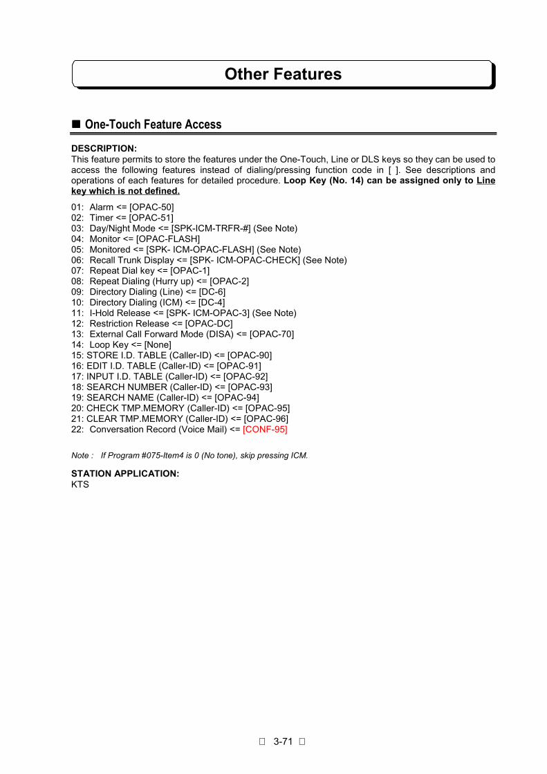
Other Features
3-71
!!!! One-Touch Feature Access
DESCRIPTION:This feature permits to store the features under the One-Touch, Line or DLS keys so they can be used toaccess the following features instead of dialing/pressing function code in [ ]. See descriptions andoperations of each features for detailed procedure. Loop Key (No. 14) can be assigned only to Linekey which is not defined.
01: Alarm <= [OPAC-50]02: Timer <= [OPAC-51]03: Day/Night Mode <= [SPK-ICM-TRFR-#] (See Note)04: Monitor <= [OPAC-FLASH]05: Monitored <= [SPK- ICM-OPAC-FLASH] (See Note)06: Recall Trunk Display <= [SPK- ICM-OPAC-CHECK] (See Note)07: Repeat Dial key <= [OPAC-1]08: Repeat Dialing (Hurry up) <= [OPAC-2]09: Directory Dialing (Line) <= [DC-6]10: Directory Dialing (ICM) <= [DC-4]11: I-Hold Release <= [SPK- ICM-OPAC-3] (See Note)12: Restriction Release <= [OPAC-DC]13: External Call Forward Mode (DISA) <= [OPAC-70]14: Loop Key <= [None]15: STORE I.D. TABLE (Caller-ID) <= [OPAC-90]16: EDIT I.D. TABLE (Caller-ID) <= [OPAC-91]17: INPUT I.D. TABLE (Caller-ID) <= [OPAC-92]18: SEARCH NUMBER (Caller-ID) <= [OPAC-93]19: SEARCH NAME (Caller-ID) <= [OPAC-94]20: CHECK TMP.MEMORY (Caller-ID) <= [OPAC-95]21: CLEAR TMP.MEMORY (Caller-ID) <= [OPAC-96]22: Conversation Record (Voice Mail) <= [CONF-95]
Note : If Program #075-Item4 is 0 (No tone), skip pressing ICM.
STATION APPLICATION:KTS

Other Features
3-72
OPERATION:To store a feature under a One-Touch or Line key:1. Press SPK.2. Press ICM key. (See Note 1)3. Press OPAC, dial 4.4. Press a desired One-Touch or Line key.5. Dial feature number (01-14,22) shown in the previous page..6. Dial ∗ .7. Press SPK.
To clear a feature stored on a One-touch or Line key:1. Press SPK.2. Press ICM key. (See Note 1)3. Press OPAC, dial 4.4. Press a One-Touch or Line key stored feature.5. Dial 00 to delete a feature stored.6. Dial ∗ .7. Press SPK.
To check an feature stored under a One-Touch or Line key:- Do not press SPK key.
1. Press CHECK.2. Press a One-Touch or Line key stored feature.3. The number set feature display.
Note 1: If Program #075-Item4 is 0 (No tone), skip pressing ICM.
RELATED SYSTEM DATA:Not applicable.
!!!! Volume Control
DESCRIPTION:The Volume Control, which is provided with all KTSs, allows easy changes to the following: LCD contraston KTS with LCD, station ringing volume, handset receiver volume, and station speaker volume control.
STATION APPLICATION:KTS

Other Features
3-73
OPERATION:To adjust LCD contrast for KTS with LCD:
- Do not lift handset.1. Press the Vol (up) or Vol (down) to increase/decrease LCD contrast while the phone is idle.
To adjust Speaker Volume:1. Press the Vol (up) or Vol (down) to increase/decrease speaker volume while the phone is handsfree
mode.
To adjust Handset Receiver Volume:1. Press the Vol (up) or Vol (down) to increase/decrease handset receiver volume.
To adjust Ringing Volume:1. Press the Vol (up) or Vol (down) to increase/decrease ringing volume while the phone is ringing or
idle mode.
RELATED SYSTEM DATA:#018-Item4: Handset Receiver Volume
!!!! DLS Console
DESCRIPTION:DLS(Direct Line Selection) Console has 24 DLS keys. Each DLS key is assigned as Feature Access key.DLS Console should be connected to KTS with LCD extension.On the TX-Z2 824 System, this DLS Console is used as DSS(Direct Station Selection) Console. EachDLS key is assigned to physical port number accordingly. (Not by extension number which is set inProgram 14.) DLS Console user can call the other extension only pressing DLS key. TX-Z2 824 Systemcan connect Maximum 3 DLS Consoles..
STATION APPLICATION:KTS with LCD
OPERATION:
– TX-Z2 824 –
1. DSS Call (One-Touch Extension Access)1. Do not Lift Handset.
orLift Handset or Press SPK.
2. Press one of DLS key.
2. Automatic Hold of Trunk Line1. On the Trunk line call.2. Press one of DLS key.
3. Unannounced Transfer1. On the Trunk line call.2. Press one of DLS key.
(Trunk Line is held and the other extension is called.)3. Hang up or press TRFR key.
(Called extension is ringing.)
4. Announced Transfer1. On the Trunk Line call.2. Press one of DLS key.
(Trunk Line is held and the other extension is called.)

Other Features
3-74
3. Make announcement.4. Hang up or press TRFR key.
(Trunk Line is transferred.)
RELATED SYSTEM DATA:Not applicable.
!!!! Headset Operation
DESCRIPTION:A KTS user can utilize a customer-provided headset in place of the handset. Like using Handsfree, usingthe handset frees up the user's hands for other work. However, Headset Operation provides privacy notavailable from Handsfree. While in the headset mode, the hook switch should be On-Hook condition.To use this facility, system requires optional item as follows;
- Recommended Headset set -- Multi-Purpose-Amplifier (8833-81-00)- Profile (1861-00, 1862-00 or 1863-00)- Cable (8800-01-01 or 8800-00-01)
(All Items are Made by GN Netcom)
STATION APPLICATION:KTS
OPERATION:To answer the Trunk Incoming Call:
1. Press SPK.
To place the Trunk Line outgoing call:1. Press SPK.2. Press an idle Line key.3. Dial telephone number.
To transfer the Trunk line:Refer to "Unannounced Transfer" and "Announced Transfer" operations. But Headset usersubstitutes "Press SPK" for "Hang up" in these operations.
RELATED SYSTEM DATA:#004-Item5: Headset operation
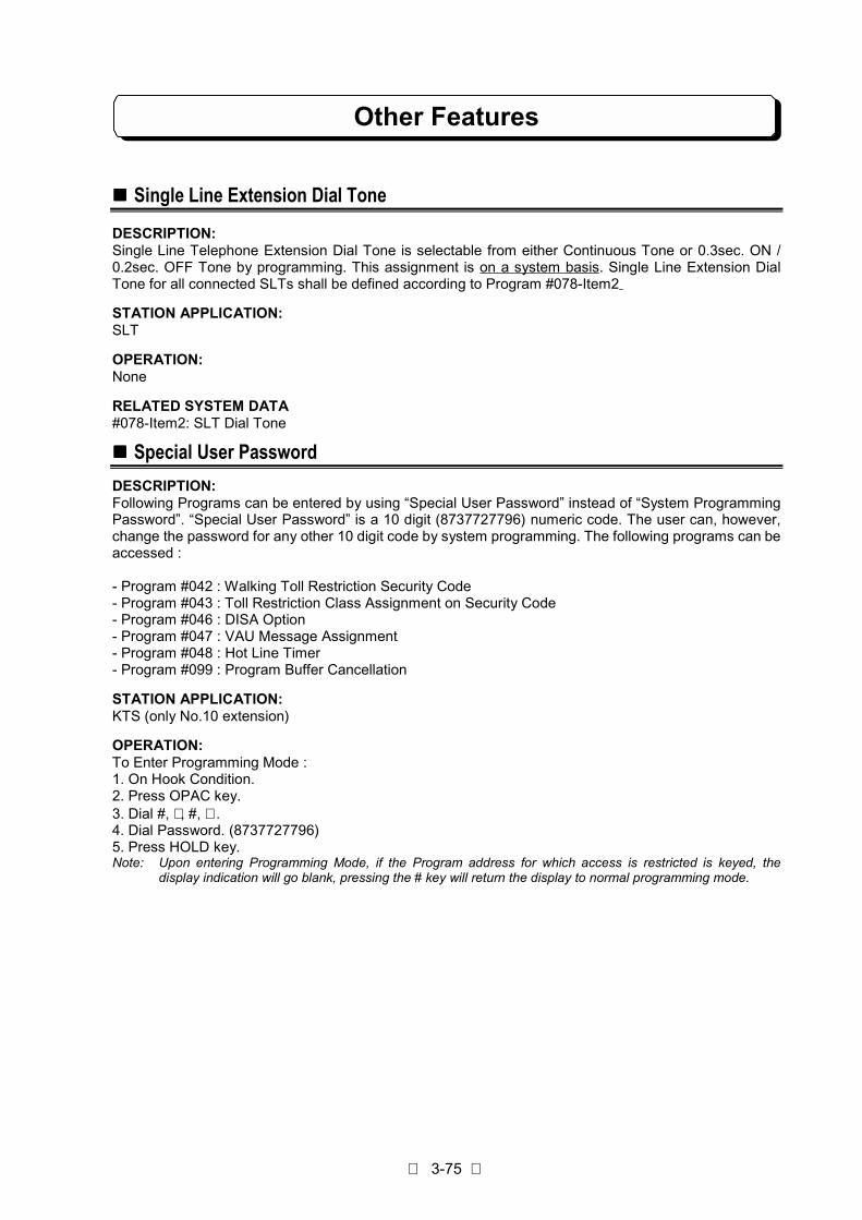
Other Features
3-75
!!!! Single Line Extension Dial Tone
DESCRIPTION:Single Line Telephone Extension Dial Tone is selectable from either Continuous Tone or 0.3sec. ON /0.2sec. OFF Tone by programming. This assignment is on a system basis. Single Line Extension DialTone for all connected SLTs shall be defined according to Program #078-Item2
STATION APPLICATION:SLT
OPERATION:None
RELATED SYSTEM DATA#078-Item2: SLT Dial Tone
!!!! Special User PasswordDESCRIPTION:Following Programs can be entered by using “Special User Password” instead of “System ProgrammingPassword”. “Special User Password” is a 10 digit (8737727796) numeric code. The user can, however,change the password for any other 10 digit code by system programming. The following programs can beaccessed :
- Program #042 : Walking Toll Restriction Security Code- Program #043 : Toll Restriction Class Assignment on Security Code- Program #046 : DISA Option- Program #047 : VAU Message Assignment- Program #048 : Hot Line Timer- Program #099 : Program Buffer Cancellation
STATION APPLICATION:KTS (only No.10 extension)
OPERATION:To Enter Programming Mode :1. On Hook Condition.2. Press OPAC key.3. Dial #, ∗ , #, ∗ .4. Dial Password. (8737727796)5. Press HOLD key.Note: Upon entering Programming Mode, if the Program address for which access is restricted is keyed, the
display indication will go blank, pressing the # key will return the display to normal programming mode.

Other Features
3-76
To exit Programming Mode :1. Return to “Program No. Input” mode.2. Press HOLD key.
RELATED SYSTEM DATA:None
!!!! Voice Mail Connection
DESCRIPTION:The TX-Z2 System is compatible with some Voice Mail Systems. This feature provides telephone userswith comprehensive Voice Messaging and Auto Attendant feature such as Call Forwarding to Voice Mail,Leave a Message, Transferring to Voice Mail, and Conversation Record.This feature is required the Nitsuko Voice Mail Interface Box.
STATION APPLICATION:Not Applicable
OPERATION:Refer to VM User’s Guide.
RELATED SYSTEM DATA:#065: NVM Connection Port (TX-Z2 824)
!!!! Caller-ID
DESCRIPTION:Refer to Caller-ID Instruction of the Part 5-1.
!!!! VAU
DESCRIPTION:Refer to VAU Instruction of the Part 5-2.
!!!! FAX Transfer
DESCRIPTION:Refer to VAU Instruction of the Part 5-2.
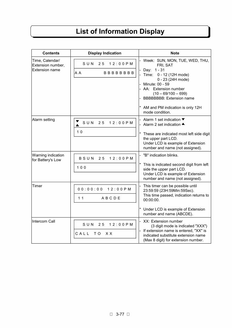
List of Information Display
3-77
Contents Display Indication Note
Time, Calendar/Extension number,Extension name
# # S U N # 2 5 # 1 2 : 0 0 P M
A A # # # # # # B B B B B B B B
- Week: SUN, MON, TUE, WED, THU,FRI, SAT
- Day: 1 - 31- Time: 0 - 12 (12H mode)
0 - 23 (24H mode)- Minute: 00 - 59- AA: Extension number
(10 – 69/100 – 699)- BBBBBBBB: Extension name
* AM and PM indication is only 12Hmode condition.
Alarm setting# # S U N # 2 5 # 1 2 : 0 0 P M
1 0 # # # # # # # # # # # # # #
- Alarm 1 set indication- Alarm 2 set indication
* These are indicated most left side digitthe upper part LCD.Under LCD is example of Extensionnumber and name (not assigned).
Warning indicationfor Battery's Low # B S U N # 2 5 # 1 2 : 0 0 P M
1 0 0 # # # # # # # # # # # # #
- "B" indication blinks.
* This is indicated second digit from leftside the upper part LCD.Under LCD is example of Extensionnumber and name (not assigned).
Timer0 0 : 0 0 : 0 0 # 1 2 : 0 0 P M
1 1 # # # # A B C D E # # #
- This timer can be possible until23:59:59 (23H:59Min:59Sec).This time passed, indication returns to00:00:00.
* Under LCD is example of Extensionnumber and name (ABCDE).
Intercom Call# # S U N # 2 5 # 1 2 : 0 0 P M
C A L L # T O # X X # # # # # #
- XX: Extension number(3 digit mode is indicated "XXX")
- If extension name is entered, "XX" isindicated substitute extension name(Max 8 digit) for extension number.
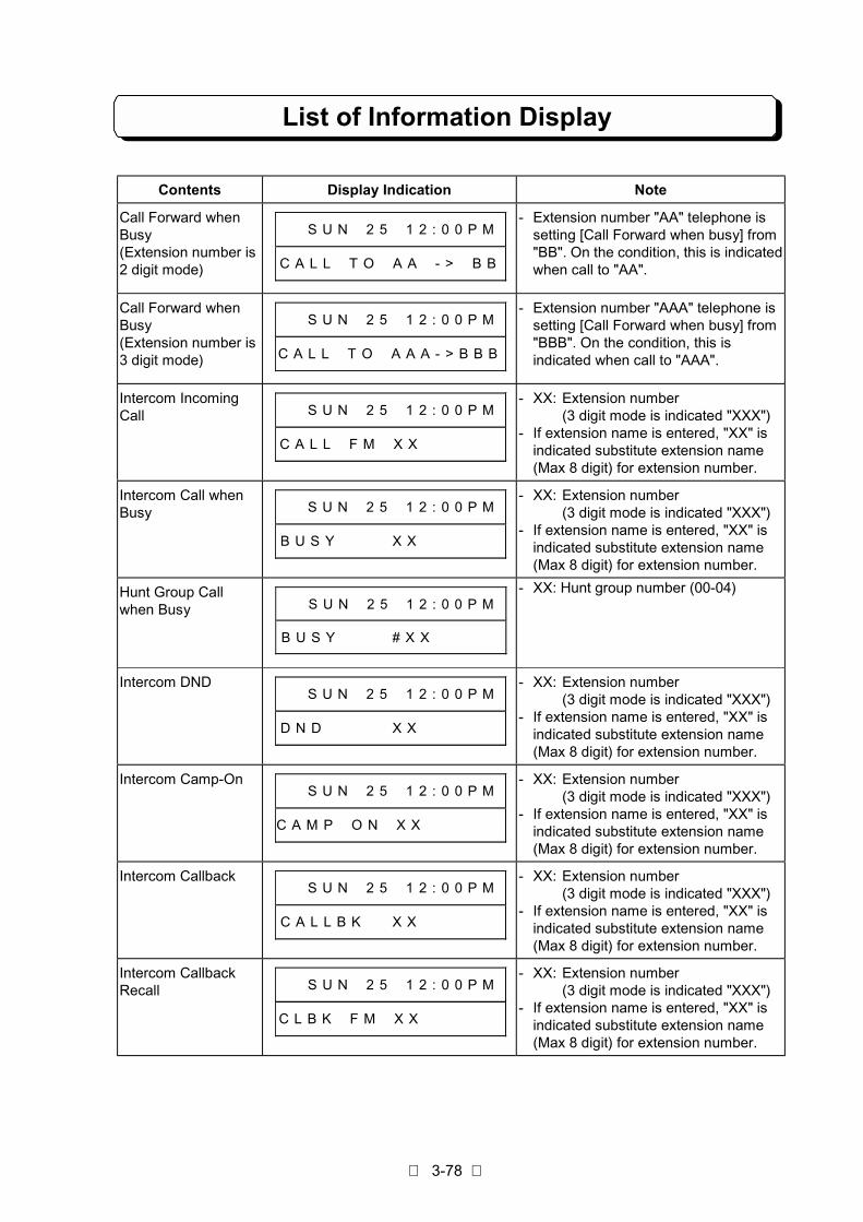
List of Information Display
3-78
Contents Display Indication Note
Call Forward whenBusy(Extension number is2 digit mode)
# # S U N # 2 5 # 1 2 : 0 0 P M
C A L L # T O # A A # - > # B B
- Extension number "AA" telephone issetting [Call Forward when busy] from"BB". On the condition, this is indicatedwhen call to "AA".
Call Forward whenBusy(Extension number is3 digit mode)
# # S U N # 2 5 # 1 2 : 0 0 P M
C A L L # T O # A A A - > B B B
- Extension number "AAA" telephone issetting [Call Forward when busy] from"BBB". On the condition, this isindicated when call to "AAA".
Intercom IncomingCall # # S U N # 2 5 # 1 2 : 0 0 P M
C A L L # F M # X X # # # # # #
- XX: Extension number(3 digit mode is indicated "XXX")
- If extension name is entered, "XX" isindicated substitute extension name(Max 8 digit) for extension number.
Intercom Call whenBusy # # S U N # 2 5 # 1 2 : 0 0 P M
B U S Y # # # # X X # # # # # #
- XX: Extension number(3 digit mode is indicated "XXX")
- If extension name is entered, "XX" isindicated substitute extension name(Max 8 digit) for extension number.
Hunt Group Callwhen Busy # # S U N # 2 5 # 1 2 : 0 0 P M
B U S Y # # # # # X X # # # # #
- XX: Hunt group number (00-04)
Intercom DND# # S U N # 2 5 # 1 2 : 0 0 P M
D N D # # # # # X X # # # # # #
- XX: Extension number(3 digit mode is indicated "XXX")
- If extension name is entered, "XX" isindicated substitute extension name(Max 8 digit) for extension number.
Intercom Camp-On# # S U N # 2 5 # 1 2 : 0 0 P M
C A M P # O N # X X # # # # # #
- XX: Extension number(3 digit mode is indicated "XXX")
- If extension name is entered, "XX" isindicated substitute extension name(Max 8 digit) for extension number.
Intercom Callback# # S U N # 2 5 # 1 2 : 0 0 P M
C A L L B K # # X X # # # # # #
- XX: Extension number(3 digit mode is indicated "XXX")
- If extension name is entered, "XX" isindicated substitute extension name(Max 8 digit) for extension number.
Intercom CallbackRecall # # S U N # 2 5 # 1 2 : 0 0 P M
C L B K # F M # X X # # # # # #
- XX: Extension number(3 digit mode is indicated "XXX")
- If extension name is entered, "XX" isindicated substitute extension name(Max 8 digit) for extension number.
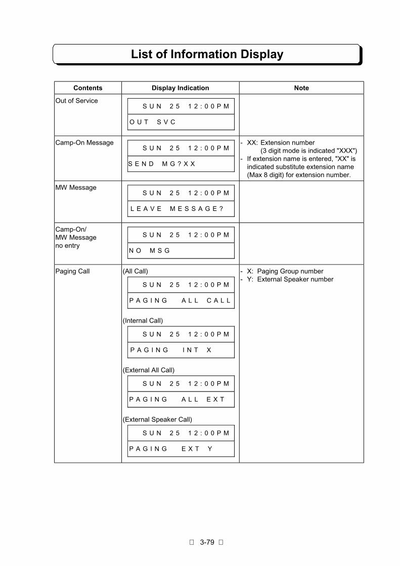
List of Information Display
3-79
Contents Display Indication Note
Out of Service# # S U N # 2 5 # 1 2 : 0 0 P M
O U T # S V C # # # # # # # # #
Camp-On Message# # S U N # 2 5 # 1 2 : 0 0 P M
S E N D # M G ? X X # # # # # #
- XX: Extension number(3 digit mode is indicated "XXX")
- If extension name is entered, "XX" isindicated substitute extension name(Max 8 digit) for extension number.
MW Message# # S U N # 2 5 # 1 2 : 0 0 P M
L E A V E # M E S S A G E ? #
Camp-On/MW Messageno entry
# # S U N # 2 5 # 1 2 : 0 0 P M
N O # M S G # # # # # # # # # #
Paging Call (All Call)
# # S U N # 2 5 # 1 2 : 0 0 P M
P A G I N G # # A L L # C A L L
(Internal Call)
# # S U N # 2 5 # 1 2 : 0 0 P M
P A G I N G # # I N T # X # # #
(External All Call)
# # S U N # 2 5 # 1 2 : 0 0 P M
P A G I N G # # A L L # E X T #
(External Speaker Call)
# # S U N # 2 5 # 1 2 : 0 0 P M
P A G I N G # # E X T # Y # # #
- X: Paging Group number- Y: External Speaker number

List of Information Display
3-80
Contents Display Indication Note
Meet-Me Answer (All Call)
# # S U N # 2 5 # 1 2 : 0 0 P M
M E E T # M E # A L L # C A L L
(Internal Call)
# # S U N # 2 5 # 1 2 : 0 0 P M
M E E T # M E # I N T # X # # #
(External All Call)
# # S U N # 2 5 # 1 2 : 0 0 P M
M E E T # M E # A L L # E X T #
(External Speaker Call)
# # S U N # 2 5 # 1 2 : 0 0 P M
M E E T # M E # E X T # Y # # #
Meet-Me Conference (All Call)
# # S U N # 2 5 # 1 2 : 0 0 P M
C O N F # # # # A L L # C A L L
(Internal Call)
# # S U N # 2 5 # 1 2 : 0 0 P M
C O N F # # # # I N T # X # # #
- X: Paging Group number- Y: External Speaker number

List of Information Display
3-81
Contents Display Indication Note
Meet-MeConference
(Conference)
# # S U N # 2 5 # 1 2 : 0 0 P M
M E E T # M E # C O N F
Call to Doorphone1/2 # # S U N # 2 5 # 1 2 : 0 0 P M
C A L L # T O # 8 8 # D O O R 1
# # S U N # 2 5 # 1 2 : 0 0 P M
C A L L # T O # 8 9 # D O O R 2
- If Doorphone name is entered,"DOOR1" and "DOOR2" are indicatedsubstitute extension name (Max 8digit) for extension number.
Incoming call fromDoorphone 1/2 # # S U N # 2 5 # 1 2 : 0 0 P M
C A L L # F M # 8 8 # D O O R 1
# # S U N # 2 5 # 1 2 : 0 0 P M
C A L L # F M # 8 9 # D O O R 2
- If Doorphone name is entered,"DOOR1" and "DOOR2" are indicatedsubstitute extension name (Max 8digit) for extension number.
Confirmation of MWsetting O U T # O F # O F F I C E # # #
M S G # T O # # X X # # # # # #
- XX: Extension number(3 digit mode is indicated "XXX")
- If extension name is entered, "XX" isindicated substitute extension name(Max 8 digit) for extension number.
* When MW Message is no setting,upper part LCD is not indicated.
Confirmation of MWto be set O U T # O F # O F F I C E # # #
M S G # F M # # X X # # # # # #
- XX: Extension number(3 digit mode is indicated "XXX")
- If extension name is entered, "XX" isindicated substitute extension name(Max 8 digit) for extension number.
* When MW Message is no setting,upper part LCD is not indicated.
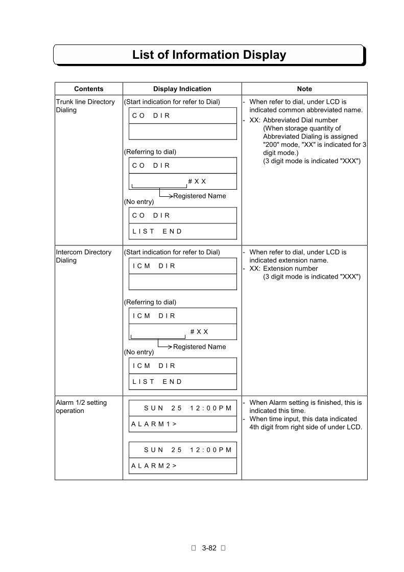
List of Information Display
3-82
Contents Display Indication Note
Trunk line DirectoryDialing
(Start indication for refer to Dial)
C O # D I R # # # # # # # # # #
(Referring to dial)
C O # D I R # # # # # # # # # #
# # # # # # # # # # X X # # # #
(No entry)
C O # D I R # # # # # # # # # #
L I S T # E N D # # # # # # # #
- When refer to dial, under LCD isindicated common abbreviated name.
- XX: Abbreviated Dial number(When storage quantity ofAbbreviated Dialing is assigned"200" mode, "XX" is indicated for 3digit mode.)(3 digit mode is indicated "XXX")
Intercom DirectoryDialing
(Start indication for refer to Dial)
I C M # D I R # # # # # # # # #
(Referring to dial)
I C M # D I R # # # # # # # # #
# # # # # # # # # # X X # # # #
(No entry)
I C M # D I R # # # # # # # # #
L I S T # E N D # # # # # # # #
- When refer to dial, under LCD isindicated extension name.
- XX: Extension number(3 digit mode is indicated "XXX")
Alarm 1/2 settingoperation # # S U N # 2 5 # 1 2 : 0 0 P M
A L A R M 1 > # # # # # # # # #
# # S U N # 2 5 # 1 2 : 0 0 P M
A L A R M 2 > # # # # # # # # #
- When Alarm setting is finished, this isindicated this time.
- When time input, this data indicated4th digit from right side of under LCD.
Registered Name
Registered Name
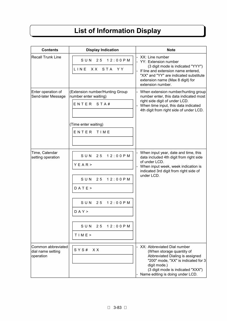
List of Information Display
3-83
Contents Display Indication Note
Recall Trunk Line# # S U N # 2 5 # 1 2 : 0 0 P M
L I N E # X X # S T A # Y Y # #
- XX: Line number- YY: Extension number
(3 digit mode is indicated "YYY")- If line and extension name entered,
"XX" and "YY" are indicated substituteextension name (Max 8 digit) forextension number.
Enter operation ofSend-later Message
(Extension number/Hunting Groupnumber enter waiting)
E N T E R # S T A # # # # # # #
(Time enter waiting)
E N T E R # T I M E # # # # # #
- When extension number/hunting groupnumber enter, this data indicated mostright side digit of under LCD.
- When time input, this data indicated4th digit from right side of under LCD.
Time, Calendarsetting operation # # S U N # 2 5 # 1 2 : 0 0 P M
Y E A R > # # # # # # # # # # #
# # S U N # 2 5 # 1 2 : 0 0 P M
D A T E > # # # # # # # # # # #
# # S U N # 2 5 # 1 2 : 0 0 P M
D A Y > # # # # # # # # # # # #
# # S U N # 2 5 # 1 2 : 0 0 P M
T I M E > # # # # # # # # # # #
- When input year, date and time, thisdata included 4th digit from right sideof under LCD.
- When input week, week indication isindicated 3rd digit from right side ofunder LCD.
Common abbreviateddial name settingoperation
S Y S # # X X # # # # # # # # #- XX: Abbreviated Dial number
(When storage quantity ofAbbreviated Dialing is assigned"200" mode, "XX" is indicated for 3digit mode.)(3 digit mode is indicated "XXX")
- Name editing is doing under LCD.

List of Information Display
3-84
Contents Display Indication Note
Extension namesetting operation S T A # # X X # # # # # # # # #
- XX: Extension number(3 digit mode is indicated "XXX")
- Name editing is doing under LCD.
Trunk name settingoperation L I N E X X # # # # # # # # #
- XX: Trunk line number- Name editing is doing under LCD.
Common Messageinput operation M S G # # X X # # # # # # # # #
- XX: Message number- Name editing is doing under LCD.
Exclusive Messageinput operation M S G # # F X X # # # # # # # #
- XX: F key number (01-02)- Name editing is doing under LCD.
Seizing Trunk LineL I N E # X X # # # # # # # # #
- XX: Line number- Dial number is indicated most right
side digit the under LCD.- If line name is entered, "XX" is
indicated substitute line name (Max 8digit) for extension number.
Abbreviated Dialingoutgoing call L I N E # X X # # # # # # # # #
# # # # # # # # # # # # # # D C
- XX: Line number- Abbreviated Dial number is indicated
most right side digit the under LCD.- Entered Dial number is indicated most
right side digit the under LCD.
Saved NumberDialing outgoing call L I N E # X X # # # # # # # # #
# # # # # # # # # # # # S A V E
- XX: Line number- Entered Dial number is indicated most
right side digit the under LCD.
Last Number Dialingoutgoing call L I N E # X X # # # # # # # # #
# # # # # # # # # # # # # L N D
- XX: Line number- Entered Dial number is indicated most
right side digit the under LCD.
Repeat Dial setting# # S U N # 2 5 # 1 2 : 0 0 P M
R E P E A T # D I A L # # # # #

List of Information Display
3-85
Contents Display Indication Note
Repeat Dial outgoingcall L I N E # X X # # # # # # # # #
# # # # # # # # # # R E P E A T
- XX: Line number- Entered Dial number is indicated most
right side digit the under LCD.
Line key confirmation (Trunk Line)
# # S U N # 2 5 # 1 2 : 0 0 P M
# # # # # L I N E # X X # K E Y
(Park Hold)
# # S U N # 2 5 # 1 2 : 0 0 P M
# # # P A R K # H O L D # K E Y
(No define)
# # S U N # 2 5 # 1 2 : 0 0 P M
# # # # # # # N O # D E F I N E
- XX: Line number- Operation for confirmation:
1. Press CHECK key.2. Press Line key for confirmation
- Line number correspond when Lampshift mode.
F1 - F10 keyconfirmation
(Individually Abbreviated Dialing/Intercom One Touch)
# # S U N # 2 5 # 1 2 : 0 0 P M
# C O / I C M # R E P A R T R Y
- Operation for confirmation:1. Press CHECK key.2. Press F1 - F10 key.
(Telephone number/Extension number)1. Press CHECK key.2. Press DC/ICM key.3. Press F1 - F10 key.
DLS1 - DLS24 keyconfirmation
(Extension number) (TX-Z 824)
# # S U N # 2 5 # 1 2 : 0 0 P M
# S T A T I O N # P O R T # X X
- XX: Extension number (Hard number)(10 - System Max.)
- Operation for confirmation:1. Press CHECK key.2. Press DLS1 - DLS24.
- XX: Line number- Operation for confirmation:
1. Press CHECK key.2. Press DLS1 - DLS24.

List of Information Display
3-86
Contents Display Indication Note
Feature Access keyset/reset
(Line key)
# # S U N # 2 5 # 1 2 : 0 0 P M
# # # # # # # # # # # # C O X X
(DLS key)
# # S U N # 2 5 # 1 2 : 0 0 P M
# # # # # # # # # # # D L S X X
(F1 - F10 key)
# # S U N # 2 5 # 1 2 : 0 0 P M
# # # # # # # # # # # # # F X X
- XX: Each key number
One-Touch FeatureAccess keyconfirmation
(ALARM key)
# # S U N # 2 5 # 1 2 : 0 0 P M
# # # # # # # A L A R M # K E Y
(TIMER key)
# # S U N # 2 5 # 1 2 : 0 0 P M
# # # # # # # T I M E R # K E Y
(Night mode set/reset)
# # S U N # 2 5 # 1 2 : 0 0 P M
# # # # # # # N I G H T # K E Y
(MONITOR set/reset)
# # S U N # 2 5 # 1 2 : 0 0 P M
# # # # # M O N I T O R # K E Y
(MONITORED set/reset)
# # S U N # 2 5 # 1 2 : 0 0 P M
# # # M O N I T O R E D # K E Y
- Operation for confirmation:1. Press CHECK key.2. Press Line/F1 - F10/DLS1 -
DLS24 key.

List of Information Display
3-87
Contents Display Indication Note
Access keyconfirmation
(Recall Trunk Display set/reset)
# # S U N # 2 5 # 1 2 : 0 0 P M
R E C A L L # L I N E # D I S P
(Repeat Dialing set/reset)
# # S U N # 2 5 # 1 2 : 0 0 P M
# R E P E A T # D I A L # K E Y
(Repeat Dialing outgoing call key)
# # S U N # 2 5 # 1 2 : 0 0 P M
# # # # H U R R Y # U P # K E Y
(Trunk Directory set/reset)
# # S U N # 2 5 # 1 2 : 0 0 P M
# # # # # # C O # D I R # K E Y
(ICM Directory set/reset)
# # S U N # 2 5 # 1 2 : 0 0 P M
# # # # # I C M # D I R # K E Y
(I-HOLD Release)
# # S U N # 2 5 # 1 2 : 0 0 P M
# # I - H O L D # P I C K # U P
(Restriction Release)
# # S U N # 2 5 # 1 2 : 0 0 P M
# R E S T . C L A S S # C H G .
(External Call Forward on DISA)
# # S U N # 2 5 # 1 2 : 0 0 P M
D I A L I N # A U T O # T R N S

List of Information Display
3-88
Contents Display Indication Note
Access keyconfirmation
(Loop key)
# # S U N # 2 5 # 1 2 : 0 0 P M
L O G I C A L # L I N E # K E Y
(Conversation Record)
# # S U N # 2 5 # 1 2 : 0 0 P M
# R E C O R D K E Y
Trunk Queuingsetting # # S U N # 2 5 # 1 2 : 0 0 P M
T R K # Q U E U I N G # # # # #
Callback from Linesetting # # S U N # 2 5 # 1 2 : 0 0 P M
C L B K # F M # L I N E # X X #
- XX: Line number- If line name is entered, "XX" is
indicated substitute line name (Max 8digit) for extension number.
Repeat Dial setting# # S U N # 2 5 # 1 2 : 0 0 P M
R E P E A T # D I A L # # # # #

List of Information Display
3-89
Contents Display Indication Note
Common AbbreviatedDialing confirmation
(10 digit for example)
# # S U N # 2 5 # 1 2 : 0 0 P M
# # # X X # 1 2 3 4 5 6 7 8 9 0
(18 digit for example)
# # S U N # 2 5 # 1 2 : 0 0 P M
# # X X # 1 2 3 4 5 6 7 8 9 0 -
# # S U N # 2 5 # 1 2 : 0 0 P M
# # # # # # # # 8 7 6 5 4 3 2 1
- XX: Abbreviated Dial number(When storage quantity ofAbbreviated Dialing is assigned"200" mode, "XX" is indicated for 3digit mode.)(3 digit mode is indicated "XXX")
- Operation for confirmation:1. Press CHECK key.2. Press DC key.3. Dial Abbreviated Dial number.
(Continued: Dial "∗ ”)
Personal AbbreviatedDialing confirmation
(10 digit for example)
# # S U N # 2 5 # 1 2 : 0 0 P M
# # F X X # 1 2 3 4 5 6 7 8 9 0
(18 digit for example)
# # S U N # 2 5 # 1 2 : 0 0 P M
# F X X # 1 2 3 4 5 6 7 8 9 0 -
# # S U N # 2 5 # 1 2 : 0 0 P M
# # # # # # # # 8 7 6 5 4 3 2 1
- XX: F-key number (01 - 10)- Operation for confirmation:
1. Press CHECK key.2. Press DC key.3. Press F1 - F10 key.
(Continued: Dial "∗ ")(When storage quantity of AbbreviatedDialing is assigned "100", and #075-Item2 is enabled, F key No. 11-20 is alsoshown.)
Intercom One-Touch(Direct StationSelection)confirmation
# # S U N # 2 5 # 1 2 : 0 0 P M
# # # # # # # # # # F X X # Y Y
- XX: F-key number (01 - 10)- YY: Extension number/ Paging,
External speaker, Doorphone Callnumber
- Operation for confirmation:1. Press CHECK key.2. Press ICM key.3. Press F1 - F10 key.
Feature Access Busy# # S U N # 2 5 # 1 2 : 0 0 P M
B U S Y # # # # # # # # # # # #

List of Information Display
3-90
Contents Display Indication Note
Trunk Queuingsetting # # S U N # 2 5 # 1 2 : 0 0 P M
T R K # Q U E U I N G # # # # #
Trunk Queuing Recall# # S U N # 2 5 # 1 2 : 0 0 P M
C L B K # F M # L I N E # X X #
- XX: Line number- If line name is entered, "XX" is
indicated substitute line name (Max 8digit) for extension number.
Dial Block setting# # S U N # 2 5 # 1 2 : 0 0 P M
D I A L # B L O C K # # # # # #
Recall Trunk Displaysetting # # S U N # 2 5 # 1 2 : 0 0 P M
R E C A L L # L I N E # D I S P
Programming mode (Enter Password)
# # S U N # 2 5 # 1 2 : 0 0 P M
PASSW ORD#@@@@@@@@
(Setting start)
P R O G R A M M I N G # # # #
# # # # # 0 0 # # # # # # # # #
(Setting finished, SW is initialized)
C H E C K # S W # S E T T I N G
# # # # # # # # # # # # # - - C
(Operation finished. Error exist)
E R R O R # # # # # # # # # # #
# # # # # # # # # # # # # # # E
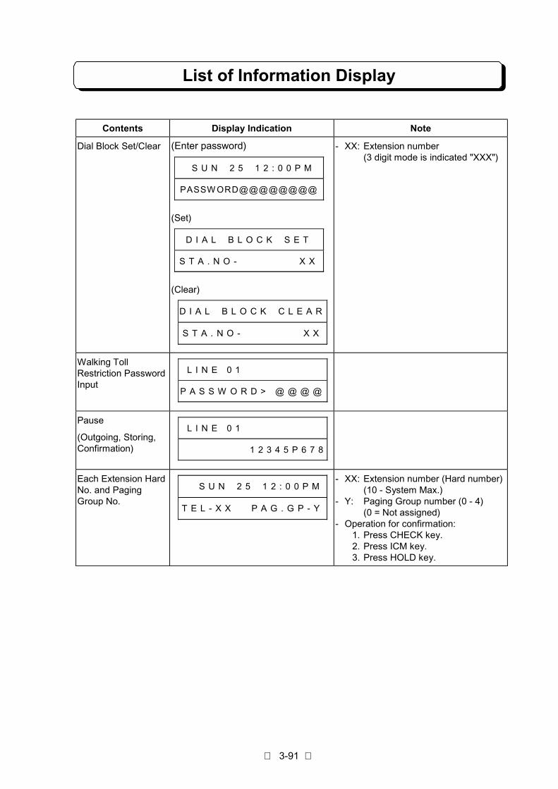
List of Information Display
3-91
Contents Display Indication Note
Dial Block Set/Clear (Enter password)
# # S U N # 2 5 # 1 2 : 0 0 P M
PASSW ORD@@@@@@@@
(Set)
D I A L # B L O C K # S E T
S T A . N O - # # # # # # # X X
(Clear)
D I A L # B L O C K # C L E A R
S T A . N O - # # # # # # # X X
- XX: Extension number(3 digit mode is indicated "XXX")
Walking TollRestriction PasswordInput
# L I N E 0 1
P A S S W O R D > @ @ @ @
Pause
(Outgoing, Storing,Confirmation)
# L I N E 0 1
1 2 3 4 5 P 6 7 8
Each Extension HardNo. and PagingGroup No.
# # S U N # 2 5 # 1 2 : 0 0 P M
T E L - X X # # P A G . G P - Y
- XX: Extension number (Hard number)(10 - System Max.)
- Y: Paging Group number (0 - 4)(0 = Not assigned)
- Operation for confirmation:1. Press CHECK key.2. Press ICM key.3. Press HOLD key.

List of Dial Number Plan
3-92
1. Dial Number Plan (KTS) on On-Hook Condition
Dial Operation Features Program
0 Seize the Idle Trunk line. 015
∗ Key Touch Tone Set/Cancel. 013
# Background Music Set/Cancel 019
2. Dial Number Plan (KTS) on Off-Hook (No Tone) Condition
Dial Operation Features Program
Extension Number Call Pickup to Intercom Call, Intercom Hold, HoldTransfer, DISA call, and Trunk incoming call(Specificextension).* Extension Number = 10 – 69 or 100 – 699
—
80 – 85 Meet-Me Answer —
88 Meet-Me Answer (Same Paging Group) —
9 Call Pickup to Doorphone call —
# Call Pickup to Intercom Call, Hold Transfer, DISA call, andTrunk Incoming Call (Extension in same paging group)
—
∗ + Extension Number + ∗ MW Cancel (Specific extension)* Extension Number = 10 – 69 or 100 – 699
—
∗ + 0 + ∗ MW Reset (All setting extension) —
∗ # + Personal Code + ∗ Dial Block SetPersonal Code = 4 digits (0000 – 9999)
035
∗ # + Personal Code + # Dial Block CancelPersonal Code = 4 digits (0000 – 9999)
035
3. Dial Number Plan (SLT) on Off-Hook Condition
Dial Operation Features Program
9 (0) Seize the Idle Trunk line 006020078
Extension Number Intercom calling* Extension Number = 10 – 69 or 100 – 699
—
80 All Call (All extensions on specified Paging Group)* External speaker calls at the same time possible. 019
81 - 84 Internal Paging (Each Paging Group) —
85 External Paging(External speaker 1)
—
88/89 Call to the Doorphone 1 or 2 —
0 (9) + Trunk Number Seize the specific trunk (Outgoing call/Answer to held line)* Trunk Number = 01 - System Max
016020078
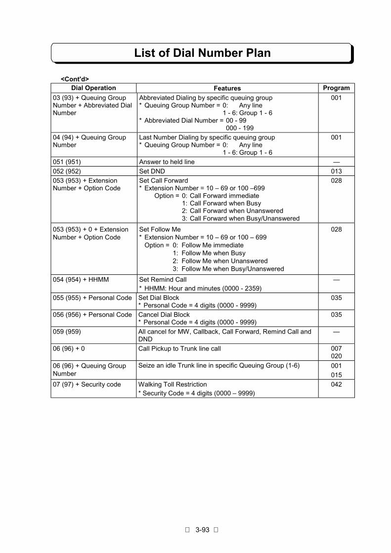
List of Dial Number Plan
3-93
<Cont'd>Dial Operation Features Program
03 (93) + Queuing GroupNumber + Abbreviated DialNumber
Abbreviated Dialing by specific queuing group* Queuing Group Number = 0: Any line
1 - 6: Group 1 - 6* Abbreviated Dial Number = 00 - 99
000 - 199
001
04 (94) + Queuing GroupNumber
Last Number Dialing by specific queuing group* Queuing Group Number = 0: Any line
1 - 6: Group 1 - 6
001
051 (951) Answer to held line —
052 (952) Set DND 013
053 (953) + ExtensionNumber + Option Code
Set Call Forward* Extension Number = 10 – 69 or 100 –699
Option = 0: Call Forward immediate1: Call Forward when Busy2: Call Forward when Unanswered3: Call Forward when Busy/Unanswered
028
053 (953) + 0 + ExtensionNumber + Option Code
Set Follow Me* Extension Number = 10 – 69 or 100 – 699
Option = 0: Follow Me immediate1: Follow Me when Busy2: Follow Me when Unanswered3: Follow Me when Busy/Unanswered
028
054 (954) + HHMM Set Remind Call* HHMM: Hour and minutes (0000 - 2359)
—
055 (955) + Personal Code Set Dial Block* Personal Code = 4 digits (0000 - 9999)
035
056 (956) + Personal Code Cancel Dial Block* Personal Code = 4 digits (0000 - 9999)
035
059 (959) All cancel for MW, Callback, Call Forward, Remind Call andDND
—
06 (96) + 0 Call Pickup to Trunk line call 007020
06 (96) + Queuing GroupNumber
Seize an idle Trunk line in specific Queuing Group (1-6) 001
015
07 (97) + Security code Walking Toll Restriction* Security Code = 4 digits (0000 – 9999)
042

List of Dial Number Plan
3-94
<Cont'd>Dial Operation Features Program
08 (98) + ExtensionNumber
Call Pickup to Intercom Call, Intercom Hold, Hold Transfer,DISA line and Trunk Incoming Call (Specific extension).* Extension Number = 10 – 69 or 100 – 699
020
08 (98) + 0 Voice Mail Direct Login 065
08 (98) + 80 – 85 Meet-Me Answer020
08(98) + 88 Meet-Me Answer (Same Paging Group)020
08 (98) + 9 Call Pickup to Doorphone call 020
09 (99) + ExtensionNumber
Seize last held Trunk line on a specific extension* Extension Number = 10 – 69 or 100 – 699
—
∗ Call back to MW —
# Call Pickup to Intercom Call, Hold Transfer, DISA call, andTrunk Incoming Call (Extension in same paging group)
—
4. Dial Number Plan (KTS) on SPK-ON (No Tone) Condition
Dial Operation Features Program
Dial 0 Seize an Idle Trunk line in the any queuing group 001015
Dial 1 - 6 Seize an Idle Trunk line in specific queuing group (1 - 6) 001015
5. Dial Number Plan (KTS) on the intercom DT condition
Dial Operation Features Program
0 Call to attendant* Attendant = No. 10 extension, specific extension
at each tenant
051
052
054
Extension Number Intercom call* Extension Number = 10 – 69 or 100 – 699
—
80 All Call (All extensions on specified Paging Group)* External speaker calls at the same time possible 019
81 - 84 Internal Paging (Each Paging Group) —
85 External Paging
(External speaker 1)
—
88/89 Call to the Doorphone 1 or 2 —
9 + Trunk Number Seize the specify trunk (Incoming Call) (KTS)* Trunk Number = 01 – System Max
016020
957 Voice Mail Conversation Recording 065
96 Trunk Incoming Call answer (KTS) 007
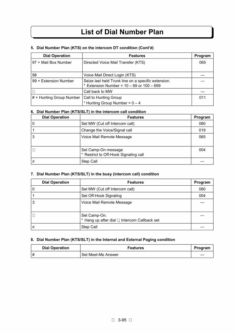
List of Dial Number Plan
3-95
5. Dial Number Plan (KTS) on the intercom DT condition (Cont'd)
Dial Operation Features Program
97 + Mail Box Number Directed Voice Mail Transfer (KTS) 065
98 Voice Mail Direct Login (KTS) —
99 + Extension Number Seize last held Trunk line on a specific extension.* Extension Number = 10 – 69 or 100 – 699
—
∗ Call back to MW —
# + Hunting Group Number Call to Hunting Group
* Hunting Group Number = 0 – 4
011
6. Dial Number Plan (KTS/SLT) in the intercom call conditionDial Operation Features Program
0 Set MW (Cut off Intercom call) 080
1 Change the Voice/Signal call 019
3 Voice Mail Remote Message 065
∗ Set Camp-On message* Restrict to Off-Hook Signaling call
004
# Step Call —
7. Dial Number Plan (KTS/SLT) in the busy (intercom call) condition
Dial Operation Features Program
0 Set MW (Cut off Intercom call) 080
1 Set Off-Hook Signaling 004
3 Voice Mail Remote Message —
∗ Set Camp-On.* Hang up after dial ∗ , Intercom Callback set
—
# Step Call —
8. Dial Number Plan (KTS/SLT) in the Internal and External Paging condition
Dial Operation Features Program
# Set Meet-Me Answer —
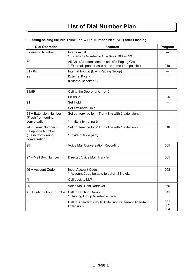
List of Dial Number Plan
3-96
9. During seizing the Idle Trunk line →→→→ Dial Number Plan (SLT) after Flashing
Dial Operation Features Program
Extension Number Intercom call* Extension Number = 10 – 69 or 100 – 699
—
80 All Call (All extensions on specific Paging Group)* External speaker calls at the same time possible 019
81 - 84 Internal Paging (Each Paging Group) —
85 External Paging
(External speaker 1)—
88/89 Call to the Doorphone 1 or 2 —
90 Flashing 026
91 Set Hold —
92 Set Exclusive Hold —
93 + Extension Number(Flash from duringconversation)
Set conference for 1 Trunk line with 2 extensions
* Invite internal party
—
94 + Trunk Number +Telephone Number(Flash from duringconversation)
Set conference for 2 Trunk line with 1 extension
* Invite outside party
016
95 Voice Mail Conversation Recording 065
97 + Mail Box Number Directed Voice Mail Transfer 065
99 + Account Code Input Account Code* Account Code be able to set until 8 digits
058
∗ Call back to MW —
∗ 7 Voice Mail Hold Retrieval 065
# + Hunting Group Number Call to Hunting Group* Hunting Group Number = 0 – 4
011
0 Call to Attendant (No.10 Extension or Tenant AttendantExtension)
051052054
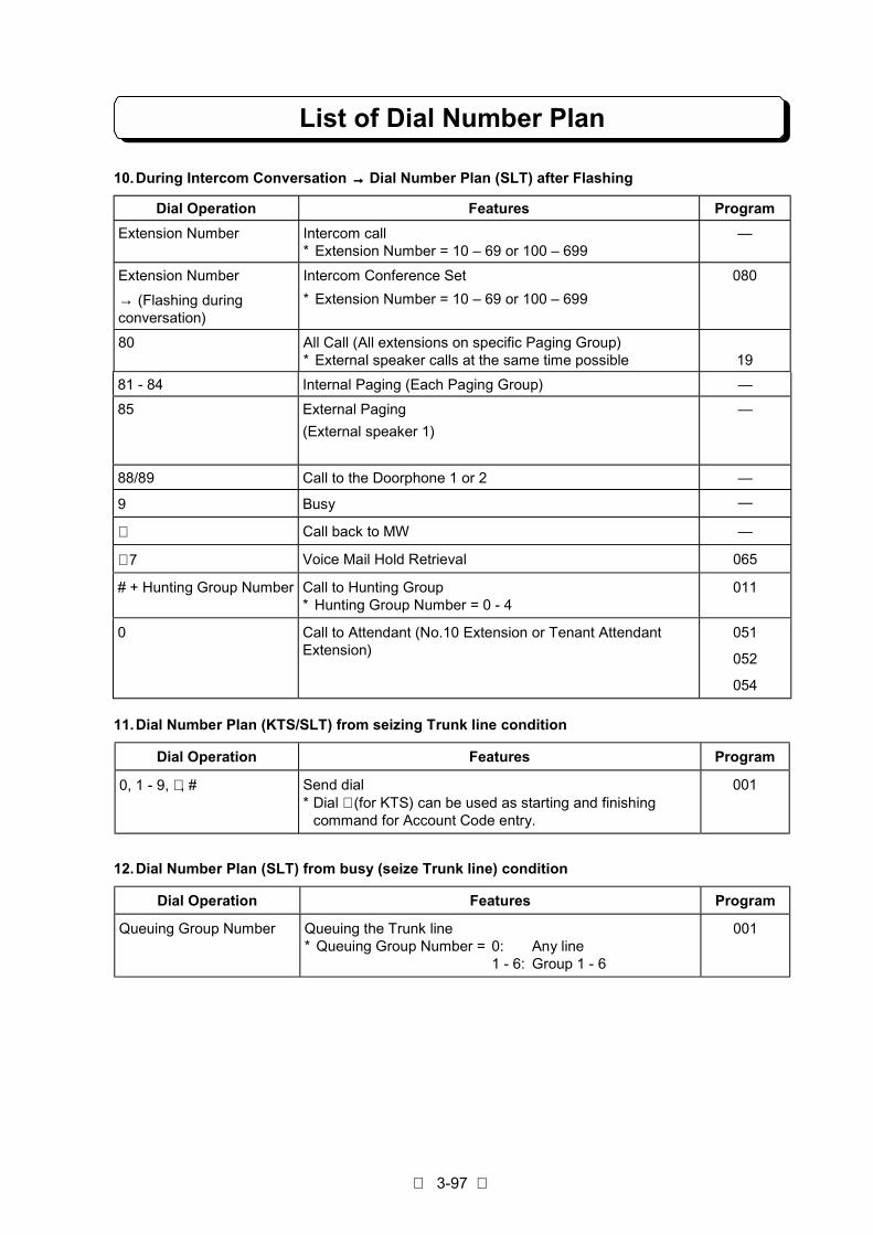
List of Dial Number Plan
3-97
10.During Intercom Conversation →→→→ Dial Number Plan (SLT) after Flashing
Dial Operation Features Program
Extension Number Intercom call* Extension Number = 10 – 69 or 100 – 699
—
Extension Number
→ (Flashing duringconversation)
Intercom Conference Set
* Extension Number = 10 – 69 or 100 – 699
080
80 All Call (All extensions on specific Paging Group)* External speaker calls at the same time possible 19
81 - 84 Internal Paging (Each Paging Group) —
85 External Paging
(External speaker 1)
—
88/89 Call to the Doorphone 1 or 2 —
9 Busy —
∗ Call back to MW —
∗ 7 Voice Mail Hold Retrieval 065
# + Hunting Group Number Call to Hunting Group* Hunting Group Number = 0 - 4
011
0 Call to Attendant (No.10 Extension or Tenant AttendantExtension)
051
052
054
11.Dial Number Plan (KTS/SLT) from seizing Trunk line condition
Dial Operation Features Program
0, 1 - 9, ∗ , # Send dial* Dial ∗ (for KTS) can be used as starting and finishing
command for Account Code entry.
001
12.Dial Number Plan (SLT) from busy (seize Trunk line) condition
Dial Operation Features Program
Queuing Group Number Queuing the Trunk line* Queuing Group Number = 0: Any line
1 - 6: Group 1 - 6
001

List of SMDR Printout Data
3-98
1. Printout DataPrintout start position
Type of DataTitle Data
Datadigits
Contents of Data
CLS 1 1 3 OTG .......Outgoing callINC......... Incoming call answer/No answerOTR .......Transfer of outgoing call lineITR .........Transfer of incoming call lineBRD .......Toll RestrictionATB ........Busy (Queuing group)BFL ........Buffer over
DATE 8 6 8 DD/MM/YY......Day/Month/Year
TIME 18 16 8 HH:MM:SS......Hours:Minutes:Seconds
LINE 25 26 2 Line number (OTG, INC, OTR, ITR, BRD)Buffer over (BFL)Queuing group number (ATB)
DURATION 30 30 8 HH:MM:SS......Hour:Minutes:SecondsConversation time (OTG, INC, OTR, ITR)Busy time (ATB)
ST# 40 40 2 Extension number
DIALED# 49 45 24 Dialed telephone number (Max. 24 digits)(OTG)
Caller’s Telephone number and/or Caller’sname (INC)
RING 64 64 5 MM:SS ............Minutes:SecondsIncoming call ringing time (INC)
ACCT NO. 71 71 8 Account Code (Max. 8 digits)
2. Printout Condition
A: Outgoing call (OTG)- Call is for Public Exchange.- After dialing telephone number, Inter-digit timer is timeout. Inter-digit timer is assigned in Program
#027-02.- After Inter-digit timer comes to timeout, conversation is longer than minimum time which is
assigned in Program #027-01.- When Program #057-Item1 is assigned "1", telephone number dialed more than digits which is
assigned in Program #059.- The telephone must be assigned by Program #061-Item4 = “0” (Printed).- When conversation is transferred while Program #057-Item2 is assigned "1", extension number of
outgoing call is printed-out.
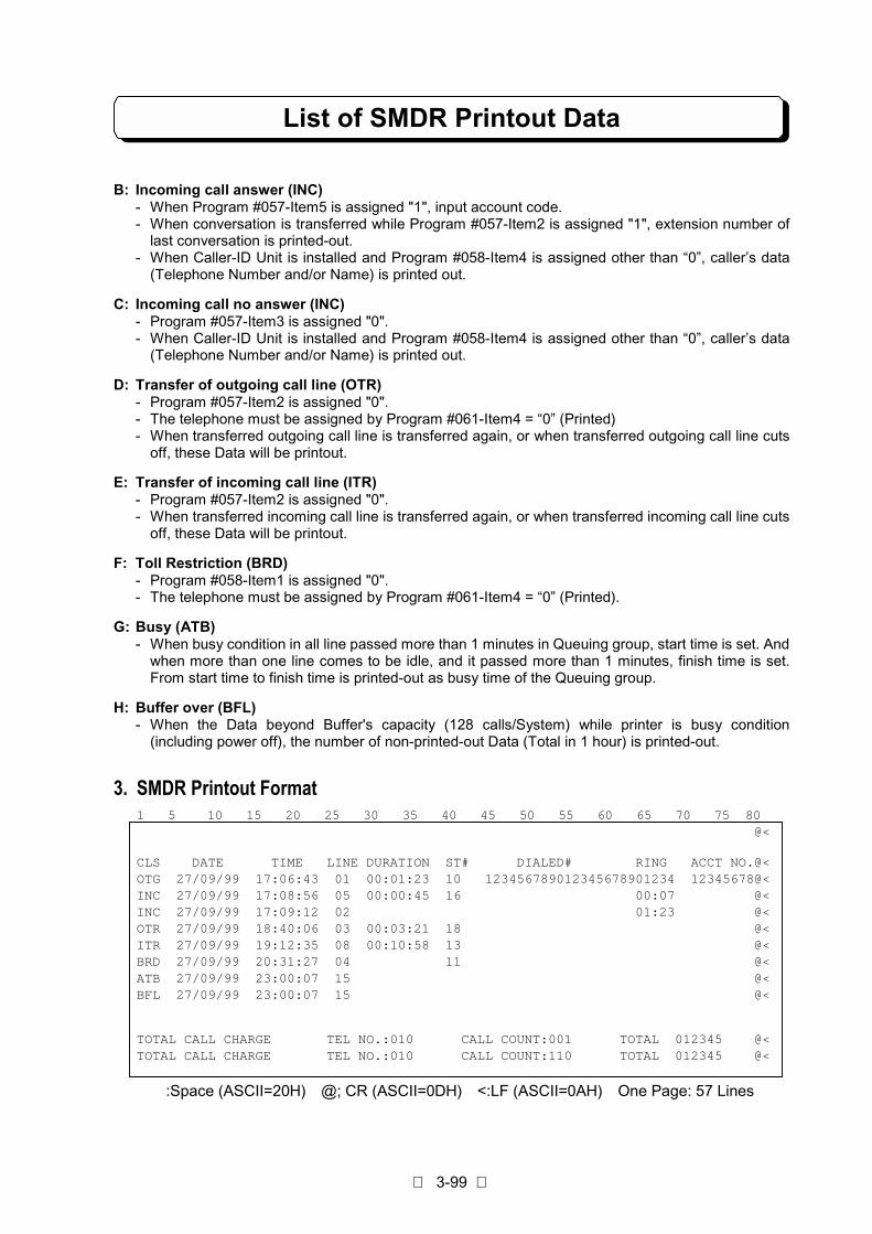
List of SMDR Printout Data
3-99
B: Incoming call answer (INC)- When Program #057-Item5 is assigned "1", input account code.- When conversation is transferred while Program #057-Item2 is assigned "1", extension number of
last conversation is printed-out.- When Caller-ID Unit is installed and Program #058-Item4 is assigned other than “0”, caller’s data
(Telephone Number and/or Name) is printed out.
C: Incoming call no answer (INC)- Program #057-Item3 is assigned "0".- When Caller-ID Unit is installed and Program #058-Item4 is assigned other than “0”, caller’s data
(Telephone Number and/or Name) is printed out.
D: Transfer of outgoing call line (OTR)- Program #057-Item2 is assigned "0".- The telephone must be assigned by Program #061-Item4 = “0” (Printed)- When transferred outgoing call line is transferred again, or when transferred outgoing call line cuts
off, these Data will be printout.
E: Transfer of incoming call line (ITR)- Program #057-Item2 is assigned "0".- When transferred incoming call line is transferred again, or when transferred incoming call line cuts
off, these Data will be printout.
F: Toll Restriction (BRD)- Program #058-Item1 is assigned "0".- The telephone must be assigned by Program #061-Item4 = “0” (Printed).
G: Busy (ATB)- When busy condition in all line passed more than 1 minutes in Queuing group, start time is set. And
when more than one line comes to be idle, and it passed more than 1 minutes, finish time is set.From start time to finish time is printed-out as busy time of the Queuing group.
H: Buffer over (BFL)- When the Data beyond Buffer's capacity (128 calls/System) while printer is busy condition
(including power off), the number of non-printed-out Data (Total in 1 hour) is printed-out.
3. SMDR Printout Format1 5 10 15 20 25 30 35 40 45 50 55 60 65 70 75 80
@<
CLS DATE TIME LINE DURATION ST# DIALED# RING ACCT NO.@<OTG 27/09/99 17:06:43 01 00:01:23 10 123456789012345678901234 12345678@<INC 27/09/99 17:08:56 05 00:00:45 16 00:07 @<INC 27/09/99 17:09:12 02 01:23 @<OTR 27/09/99 18:40:06 03 00:03:21 18 @<ITR 27/09/99 19:12:35 08 00:10:58 13 @<BRD 27/09/99 20:31:27 04 11 @<ATB 27/09/99 23:00:07 15 @<BFL 27/09/99 23:00:07 15 @<
TOTAL CALL CHARGE TEL NO.:010 CALL COUNT:001 TOTAL 012345 @<TOTAL CALL CHARGE TEL NO.:010 CALL COUNT:110 TOTAL 012345 @<
:Space (ASCII=20H) @; CR (ASCII=0DH) <:LF (ASCII=0AH) One Page: 57 Lines

DISA Operation Flowchart
3-100
This flowchart shows DISA operations with VAU Message.
If the VAU Message is not set at the Messagearea, the process will be skipped.
Note 1. Unused port should be assigned as DISA port.2. VAU card has 2 talk-paths.3. Refer to the "External Call Forward on the
DISA line".4. Program #066-Item2.5. Program #046, 048.6. Refer to the "Group Hunt".7. Program #017-Item5.8. Calling duration time is defined in "Program
#066-Item5".9. Extension calling time is defined in
“Program#066-Item3”.10. When the FAX port is assigned in Program
#075-Item8, Dial tone shall not be sent.
DISA Incoming
External Call Forward
Message(VAU)
Transfer
Empty aDISA Port?
External Callforward Mode?
Night Mode?
1st/2nd NightMessage(VAU)
3
1st/2nd AutoAttendant
Message(VAU)
1 5 NormalIncoming
Dial Tone
Dial, CNG orTimeout?
"#" + Securitycode?
Trunk to Trunk
ExtensionNumber?
"8" + Hunt GPNo.?
Idle Ext.there ?
4
ErrorMessage(VAU)
Busy Tone
Dial # & * ?
1 2
Called Ext.setAbsent Mode?
2 Called Ext. setDND?
Called Ext.Busy?
Call toExtension
Operator there?
Transfer toOperator
Message(VAU)
Call to Operator
Answer or not?
Operator Call?
Transfer toOperator
Message(VAU)
Operator there?
Call to Operator
Answer or not?
Operator Call
3
Cut OffMessage(VAU)
Cut Off
ExtensionAccess
2 6
4
7
3
Not Empty
NoEmpty
Night
Day
Time Out
Dial
CorrectIncorrect
Incorrect
Incorrect Correct
Correct
Yes
Yes
Yes
Yes
Yes
Yes
Yes
Yes Answer
Answer
No
No
No
No
No
No
No
No
No
No
Empty a VAUPath?
Empty
Not Empty
Yes
10
10
Note 1
Note 2
Note 3
Note 4
Note 5
Note 6
Note 9
Note 7
Note 8
Note 8
Note 7
FAXconnected?
FAX Transfer
CNG
2
8
8
Yes
No
If VAU Message is not set at the Message area,the Message process will be skipped to next.
Note 10
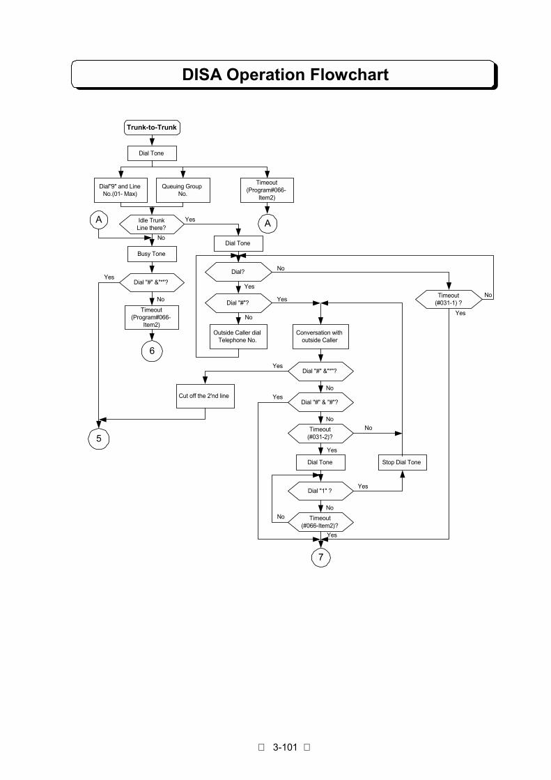
DISA Operation Flowchart
3-101
Trunk-to-Trunk
Dial Tone
Idle TrunkLine there?
Dial"9" and LineNo.(01- Max)
Busy Tone
Dial "#" &"*"?
Timeout(Program#066-
Item2)
Queuing GroupNo.
Timeout(Program#066-
Item2)
Dial Tone
Dial?
Dial "#"?
Outside Caller dialTelephone No.
Conversation withoutside Caller
Dial "#" &"*"?
Cut off the 2'nd lineDial "#" & "#"?
Timeout(#031-2)?
Dial Tone
Dial "1" ?
Timeout(#066-Item2)?
Stop Dial Tone
Timeout(#031-1) ?
6
7
A
5
A Yes
Yes
Yes
Yes
Yes
Yes
Yes
Yes
Yes
Yes
No
No
No
No
No
No
No
No
No
No

PART 4
SYSTEM PROGRAMMING
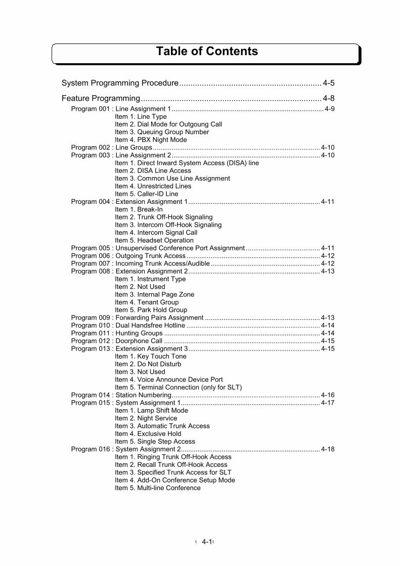
-4-1-
Table of Contents
System Programming Procedure............................................................... 4-5
Feature Programming................................................................................ 4-8Program 001 : Line Assignment 1.................................................................................. 4-9 Item 1. Line Type Item 2. Dial Mode for Outgoung Call Item 3. Queuing Group Number Item 4. PBX Night ModeProgram 002 : Line Groups.......................................................................................... 4-10Program 003 : Line Assignment 2................................................................................ 4-10 Item 1. Direct Inward System Access (DISA) line Item 2. DISA Line Access Item 3. Common Use Line Assignment Item 4. Unrestricted Lines Item 5. Caller-ID LineProgram 004 : Extension Assignment 1....................................................................... 4-11 Item 1. Break-In Item 2. Trunk Off-Hook Signaling Item 3. Intercom Off-Hook Signaling Item 4. Intercom Signal Call Item 5. Headset OperationProgram 005 : Unsupervised Conference Port Assignment ........................................ 4-11Program 006 : Outgoing Trunk Access........................................................................ 4-12Program 007 : Incoming Trunk Access/Audible........................................................... 4-12Program 008 : Extension Assignment 2....................................................................... 4-13 Item 1. Instrument Type Item 2. Not Used Item 3. Internal Page Zone Item 4. Tenant Group Item 5. Park Hold GroupProgram 009 : Forwarding Pairs Assignment .............................................................. 4-13Program 010 : Dual Handsfree Hotline ........................................................................ 4-14Program 011 : Hunting Groups .................................................................................... 4-14Program 012 : Doorphone Call .................................................................................... 4-15Program 013 : Extension Assignment 3....................................................................... 4-15 Item 1. Key Touch Tone Item 2. Do Not Disturb Item 3. Not Used Item 4. Voice Announce Device Port Item 5. Terminal Connection (only for SLT)Program 014 : Station Numbering................................................................................ 4-16Program 015 : System Assignment 1........................................................................... 4-17 Item 1. Lamp Shift Mode Item 2. Night Service Item 3. Automatic Trunk Access Item 4. Exclusive Hold Item 5. Single Step AccessProgram 016 : System Assignment 2........................................................................... 4-18 Item 1. Ringing Trunk Off-Hook Access Item 2. Recall Trunk Off-Hook Access Item 3. Specified Trunk Access for SLT Item 4. Add-On Conference Setup Mode Item 5. Multi-line Conference
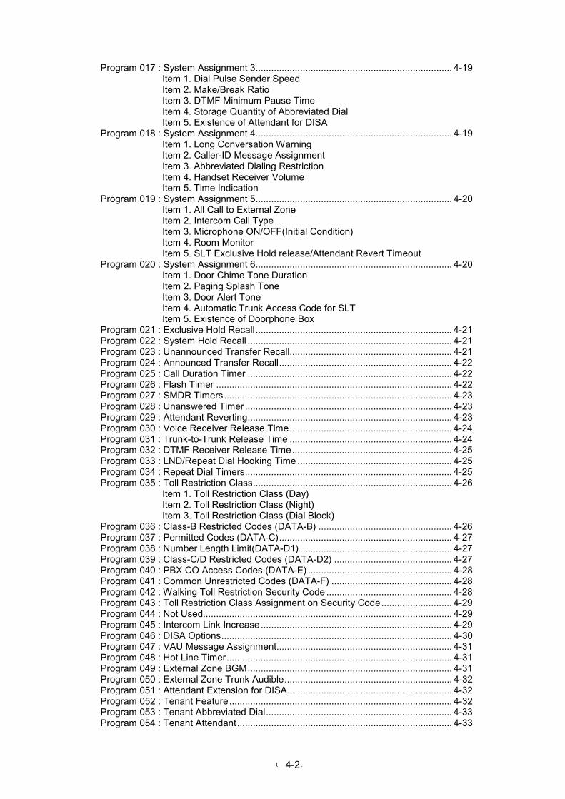
-4-2-
Program 017 : System Assignment 3........................................................................... 4-19 Item 1. Dial Pulse Sender Speed Item 2. Make/Break Ratio Item 3. DTMF Minimum Pause Time Item 4. Storage Quantity of Abbreviated Dial Item 5. Existence of Attendant for DISAProgram 018 : System Assignment 4........................................................................... 4-19 Item 1. Long Conversation Warning Item 2. Caller-ID Message Assignment Item 3. Abbreviated Dialing Restriction Item 4. Handset Receiver Volume Item 5. Time IndicationProgram 019 : System Assignment 5........................................................................... 4-20 Item 1. All Call to External Zone Item 2. Intercom Call Type Item 3. Microphone ON/OFF(Initial Condition) Item 4. Room Monitor Item 5. SLT Exclusive Hold release/Attendant Revert TimeoutProgram 020 : System Assignment 6........................................................................... 4-20 Item 1. Door Chime Tone Duration Item 2. Paging Splash Tone Item 3. Door Alert Tone Item 4. Automatic Trunk Access Code for SLT Item 5. Existence of Doorphone BoxProgram 021 : Exclusive Hold Recall........................................................................... 4-21Program 022 : System Hold Recall .............................................................................. 4-21Program 023 : Unannounced Transfer Recall.............................................................. 4-21Program 024 : Announced Transfer Recall.................................................................. 4-22Program 025 : Call Duration Timer .............................................................................. 4-22Program 026 : Flash Timer .......................................................................................... 4-22Program 027 : SMDR Timers....................................................................................... 4-23Program 028 : Unanswered Timer ............................................................................... 4-23Program 029 : Attendant Reverting.............................................................................. 4-23Program 030 : Voice Receiver Release Time.............................................................. 4-24Program 031 : Trunk-to-Trunk Release Time .............................................................. 4-24Program 032 : DTMF Receiver Release Time............................................................. 4-25Program 033 : LND/Repeat Dial Hooking Time ........................................................... 4-25Program 034 : Repeat Dial Timers............................................................................... 4-25Program 035 : Toll Restriction Class............................................................................ 4-26 Item 1. Toll Restriction Class (Day) Item 2. Toll Restriction Class (Night) Item 3. Toll Restriction Class (Dial Block)Program 036 : Class-B Restricted Codes (DATA-B) ................................................... 4-26Program 037 : Permitted Codes (DATA-C).................................................................. 4-27Program 038 : Number Length Limit(DATA-D1) .......................................................... 4-27Program 039 : Class-C/D Restricted Codes (DATA-D2) ............................................. 4-27Program 040 : PBX CO Access Codes (DATA-E) ....................................................... 4-28Program 041 : Common Unrestricted Codes (DATA-F) .............................................. 4-28Program 042 : Walking Toll Restriction Security Code ................................................ 4-28Program 043 : Toll Restriction Class Assignment on Security Code........................... 4-29Program 044 : Not Used............................................................................................... 4-29Program 045 : Intercom Link Increase......................................................................... 4-29Program 046 : DISA Options........................................................................................ 4-30Program 047 : VAU Message Assignment................................................................... 4-31Program 048 : Hot Line Timer...................................................................................... 4-31Program 049 : External Zone BGM.............................................................................. 4-31Program 050 : External Zone Trunk Audible................................................................ 4-32Program 051 : Attendant Extension for DISA............................................................... 4-32Program 052 : Tenant Feature..................................................................................... 4-32Program 053 : Tenant Abbreviated Dial....................................................................... 4-33Program 054 : Tenant Attendant.................................................................................. 4-33
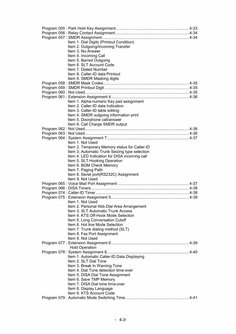
-4-3-
Program 055 : Park Hold Key Assignment................................................................... 4-33Program 056 : Relay Contact Assignment ................................................................... 4-34Program 057 : SMDR Assignment ............................................................................... 4-34 Item 1. Dial Digits (Printout Condition) Item 2. Outgoing/Incoming Transfer Item 3. No Answer Item 4. Incoming Call Item 5. Barred Outgoing Item 6. SLT Account Code Item 7. Dialed Number Item 8. Caller-ID data Printout Item 9. SMDR Masking digitsProgram 058 : SMDR Mask Codes.............................................................................. 4-35Program 059 : SMDR Printout Digit ............................................................................. 4-35Program 060 : Not Used............................................................................................... 4-35Program 061 : Extension Assignment 4....................................................................... 4-36 Item 1. Alpha-numeric Key pad assignment Item 2. Caller-ID data Indication Item 3. Caller-ID table editing Item 4. SMDR outgoing information print Item 5. Doorphone call/answer Item 6. Call Charge SMDR outputProgram 062 : Not Used............................................................................................... 4-36Program 063 : Not Used............................................................................................... 4-36Program 064 : System Assignment 7........................................................................... 4-37 Item 1. Not Used Item 2. Temporary Memory status for Caller-ID Item 3. Automatic Trunk Seizing type selection Item 4. LED Indication for DISA incoming call Item 5. SLT Hooking Operation Item 6. BGM Check Memory Item 7. Paging Path Item 8. Serial port(RS232C) Assignment Item 9. Not UsedProgram 065 : Voice Mail Port Assignment ................................................................. 4-37Program 066 : DISA Timers ......................................................................................... 4-38Program 074 : Caller-ID Timer ..................................................................................... 4-38Program 075 : Extension Assignment 5....................................................................... 4-39 Item 1. Not Used Item 2. Personal Abb.Dial Area Arrangement Item 3. SLT Automatic Trunk Access Item 4. KTS Off-Hook Mode Selection Item 5. Long Conversation Cutoff Item 6. Hot line Mode Selection Item 7. Trunk dialing method (SLT) Item 8. Fax Port Assignment Item 9. Not UsedProgram 077 : Extension Assignment 6....................................................................... 4-39 Hold OperationProgram 078 : System Assignment 8........................................................................... 4-40 Item 1. Automatic Caller-ID Data Displaying Item 2. SLT Dial Tone Item 3. Break In Warning Tone Item 4. Dial Tone detection time-over Item 5. DISA Dial Tone Assignment Item 6. Save TMP Memory Item 7. DISA Dial tone time-over Item 8. Display Language Item 9. KTS Account CodeProgram 079 : Automatic Mode Switching Time.......................................................... 4-41

-4-4-
Program 080 : System Assignment 9........................................................................... 4-41 Item 1. Message Waiting Item 2. Trunk Queuing Item 3. Not Used Item 4. Internal Conference Item 5. On-hook Transfer Item 6. Group Hunt Mode Item 7. Unsupervised Conference Extension Item 8. Call Charge Format Item 9. Dial buffering timer for SLT(DTMF)Program 081 : Not Used............................................................................................... 4-41Program 082 : Long Conversation Cutoff Timer .......................................................... 4-42Program 083 : Line Assignment 3................................................................................ 4-42 Item 1. Not Used Item 2. Optional/Fixed Rate Table Selection Item 3. Dial Tone Detection Item 4. Busy Tone Detection Item 5. Not Used Item 6. Not Used Item 7. Not Used Item 8. Not Used Item 9. Not UsedProgram 084 : Group Hunt Calling Timer .................................................................... 4-43Program 085 : Not Used............................................................................................... 4-43Program 086 : Dial Tone Detection Timer ................................................................... 4-43Program 087 : Hold Disable Timer............................................................................... 4-43Program 088 : Door Relay Timer ................................................................................. 4-44Program 089 : Dial Wait Timer..................................................................................... 4-44Program 090 : Error Check .......................................................................................... 4-44Program 091 : Function Key Initialization..................................................................... 4-45Program 092 : Program Entry Password ..................................................................... 4-45Program 093 : Software Version .................................................................................. 4-45Program 094 : Caller-ID Table Clear............................................................................ 4-46Program 095 : Sub-CPU Timers .................................................................................. 4-46Program 096 : Charge Code Table ............................................................................. 4-46Program 097 : Charge Rate Table .............................................................................. 4-47Program 098 : Maximum Call Charge ......................................................................... 4-47Program 099 : Program Buffer Cancellation ................................................................ 4-47Program 100 : Caller-ID Detection Timers................................................................... 4-48Program 101 : Dial Tone Detection Timers ................................................................. 4-48Program 102 : One Cycle Time for Tone Detection..................................................... 4-49Program 103 : Tone On/Off time for Tone Detection ................................................... 4-49Program 104 : Tone On/Off count for Tone Detection ................................................. 4-50Program 105 : DTMF Tone On/Off Detection Time ..................................................... 4-50Program 106 : Hot Line Destination Number ............................................................... 4-50Program 107 : CIDU Options ....................................................................................... 4-51Program 108 : DTMF Acknowledge Signal .................................................................. 4-51Program 109 : RS232C Port Setup.............................................................................. 4-51 Item 1. Speed (bps) for SMDR Item 2. Data bits Item 3. Parity Item 4. Stop bits Item 5. Not UsedProgram 110 : Transmit Level Attenuation for MODEMU............................................ 4-52
System Data Error Condition ................................................................... 4-53
Appendix 4-54

-4-5-
System Programming Procedure
Description
TX-Z2 824 System user can change the System Data flexibly. TX-Z2 824 System Programming isavailable only from the display telephone that is connected to physical port No. 1.
System Initialization
1. Power Supply switch (AC Power Switch) is OFF condition.2. When entering Programming Mode at first time, the SW1 on the NX8E-408M-M1 unit should be
set at the left side to INT as the illustration. Power up the CPU. The system is initialized withthe default values.
1
ETH1 ETH2 CO4 CO3 CO2 CO1 No.17 No.16 No.15 No.14 No.13 No.12 No.11 No.10
CN2
INT 1
SW1
SW2
SW1
INT
NX8E-408M-M1
AC PowerSwitch

-4-6-
System Programming Procedure
3. After you changed System Data, you must set the SW1 knob to right side to 1 to protect yourSystem Data. This switch must always remain in the 1 position for normal operation.
(Refer to "Enter the System Data Setting Operation")
NOTICE
If you exited Programming Mode without setting Sw1 to the right position, the Display indicates asfollows;
C H E C K # S W # S E T T I N G
# # # # # # # # # # # # # - - C
To correct this;
1. Press #. (Return to the Programming Mode)2. Change the SW1 to 1 position.3. Press HOLD key. (Exit from Programming Mode)
1
SW1
INT
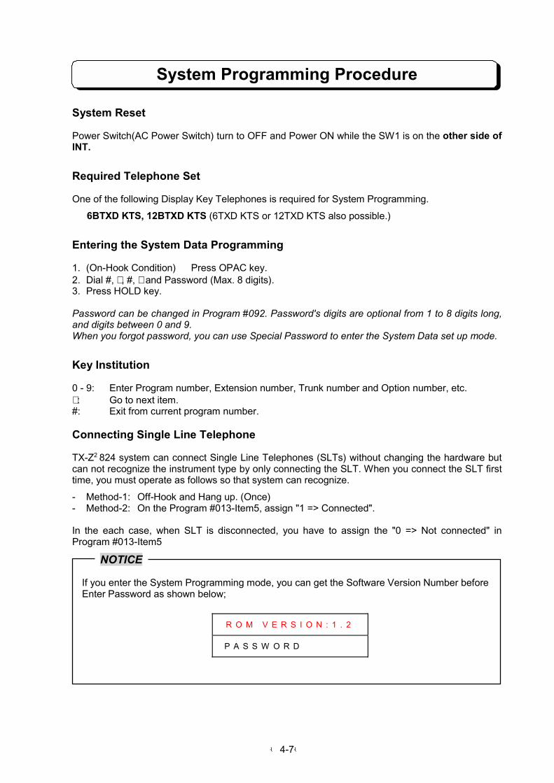
-4-7-
System Programming Procedure
System Reset
Power Switch(AC Power Switch) turn to OFF and Power ON while the SW1 is on the other side ofINT.
Required Telephone Set
One of the following Display Key Telephones is required for System Programming.
6BTXD KTS, 12BTXD KTS (6TXD KTS or 12TXD KTS also possible.)
Entering the System Data Programming
1. (On-Hook Condition) Press OPAC key.2. Dial #, ∗ , #, ∗ and Password (Max. 8 digits).3. Press HOLD key.
Password can be changed in Program #092. Password's digits are optional from 1 to 8 digits long,and digits between 0 and 9.When you forgot password, you can use Special Password to enter the System Data set up mode.
Key Institution
0 - 9: Enter Program number, Extension number, Trunk number and Option number, etc.∗ : Go to next item.#: Exit from current program number.
Connecting Single Line Telephone
TX-Z2 824 system can connect Single Line Telephones (SLTs) without changing the hardware butcan not recognize the instrument type by only connecting the SLT. When you connect the SLT firsttime, you must operate as follows so that system can recognize.
- Method-1: Off-Hook and Hang up. (Once)- Method-2: On the Program #013-Item5, assign "1 => Connected".
In the each case, when SLT is disconnected, you have to assign the "0 => Not connected" inProgram #013-Item5
NOTICE
If you enter the System Programming mode, you can get the Software Version Number before Enter Password as shown below;
R O M V E R S I O N : 1 . 2
P A S S W O R D

-4-8-
Feature Programming
To program an option:
1. Dial program number (001 - 999).2. Dial ∗ .3. Enter the required information as shown in programming entry. (under each program
description).4. Dial ∗ .5. Repeat steps 3 - 4 if there is more than one entry. (extension , trunks, etc.)6. Dial # to exit the current program number.
Example of Change Programming from default
Program #001 Each Line Assignment 1 (Method)Dial Display Meaning
1 PROGRAMMING001
Programming No. 001
∗ LINE ASSIGNMENT1001-00
1 LINE ASSIGNMENT1001-01
Line No. 1
∗ LINE ASSIGNMENT1 001-01 -0
1 LINE ASSIGNMENT1 001-01 -1
Item1 :Assign the line type
∗ LINE ASSIGNMENT1 001-01 -1-1
Display the default value(1: CO Line)
3 LINE ASSIGNMENT1 001-01 -1-3
Change 1(CO line) to 3(Behind PBX)
∗ LINE ASSIGNMENT1 001-01 -2-1
Display the default of Item2(Dial Mode 1: DTMF)
∗ LINE ASSIGNMENT1 001-01 -3-1
Display the default of Item3(Queuing Group 1)
4 LINE ASSIGNMENT1 001-01 -3-4
Change Queuing Group 1 toGroup 4.
∗ LINE ASSIGNMENT1 001-01 -4-0
Display the default of Item4(PBX Night Mode 0: Disable )
1 LINE ASSIGNMENT1 001-01 -4-1
Change Disable to Enable(PBX Night Mode 1: Enable )
∗ LINE ASSIGNMENT1 001-01 -5-0
Skip this Item.
∗ LINE ASSIGNMENT1 001-02 -1-1
Ready for Line No.2
# PROGRAMMING000
Exit this Item.
End (At item number input condition)
1. Press "HOLD" key.
Note 1: When SW1 on the NX8E-408M-A1 Unit is set to INT side or error Data are programmed,you cannot exit the programming mode.
Note 2: If you enter programs which are not described in this manual e.g. No. 067 to 073 , exit themwithout changing data. These programs are for other options.

-4-9-
Program 001 : Line Assignment 1
This program assigns Line Type (CO/PBX), Dial Mode (Pulse/DTMF), Queue Group, and PBX NightMode to each outside line.
Display Indication Input Data Initial
L I N E # A S S I G N M E N T 1
# # # # # 0 0 1 - L N - I T - X
LN. Line number (01 - System Max)
IT . Item number (1 - 4)
Item1. Line Type0: No connection *When the line is unused, the line must be assigned.1: CO Line: *If normal CO line is connected.3: PBX Line: *If behind PBX line (SLT port of PBX) is connected.
Item2. Dial Mode for outgoing call0: DP (Dial Pulse) 1: DTMF
Item3. Queuing Group Number 0: Not assigned
1 - 6: Group 1 - Group 6
*If an extension user make Camp-on (Line Queuing), Automatic Repeat Dial or etc., one of the line on the selected queuing group is seized.
Item4. PBX Night Mode0: Disable 1: Enable
*In the PBX Night Mode, the lines connected to PBX are switched to real CO lines. If you have a PBX CO access code programmed with a dialed number for abbreviated dialing, such as “9” “pause” “81448111111”, the “9” and “pause” will be omitted.
(ALL)
Item1: 1Item2: 1Item3: 1Item4: 0

-4-10-
Program 002 : Line Groups
This program assigns CO/PBX lines into groups. The line groups are assigned to an extension forOutgoing and Incoming calls. Only consecutive lines can be grouped (e.g., lines 3,4,5). Lines in onegroup can overlap with lines in another.
Display Indication Input Data Initial
L I N E # G R O U P S # # # # #
# # # # # 0 0 2 - G P - S T - E D
GP. Line group number (01 - 30)
ST. Lowest numbered line in group(01 - System Max)
ED. Highest numbered line in group(01 - System Max)
(Group 1)ST: 01ED: 08
(Other GP)ST: 00ED: 00
*This command can assign as example;Line Group(GP) Lowest Line(ST) Highest Line(ED) Purpose for
1 01 08 Operator2 01 03 Sales Staff3 04 06 Customer Support4 07 08 Director
Program 003 : Line Assignment 2
This program assigns DISA line, DISA Access Mode, Common Use Line, Unrestricted Line andCaller-ID Line to an outside line.
Display Indication Input Data Initial
L I N E # A S S I G N M E N T 2
# # # # # 0 0 3 - L N - I T - X
LN. Line number (01 - System Max)
IT. Item number (1 – 5)
Item1. Direct Inward System Access (DISA)line0: Disable 1: Enable
Item2. DISA Line Access0: No access 1: Day mode2: Night mode 3: Day and Night mode
Item3. Common Use Line Assignment0: Cannot use as a common line1: Can use as a common line*The meaning of Common Use Line is that all extension can use this Trunk line regard-less of the Trunk Line group.
Item4. Unrestricted Lines0: Restricted 1: Non-Restricted*If “Non-Restricted” is assigned, Toll
restriction does not work on the line.
Item5. Caller-ID Line0: Disable 1: Enable*If trunk has Caller-ID signal, assign for “Enable”. Otherwise system will not detect Caller-ID signal.
(ALL)
Item1: 0Item2: 0Item3: 0Item4: 0Item5: 1

-4-11-
Program 004 : Extension Assignment 1
This program assigns the following functions for each extension.
Display Indication Input Data Initial
S T N # A S S I G N M E N T 1
# # # # # 0 0 4 - S T - I T - X
ST. Extension number (10 - System Max)
IT. Item number (1-5)
Item1. Break-In0: Not allowed1: Allowed with tone2: Allowed without tone*There are 2 modes to activate the Break-Infunction which is “with tone” and “withouttone”. If Break-In function is activate by withor without tone, assigned extension allowedto receive Break-In.
Item2. Trunk Off-Hook Signaling0: Disable 1: Enable*If disable the off-hook signaling function, the extension does not ring for incoming call while talking. Extension user must lift handset to get the off-hook signaling.
Item3. Intercom Off-Hook Signaling0: None 1: When Dial 2: When Busy
Item4. Intercom Signal Call0: Disable 1: Enable
Item5. Headset operation0: Disable 1: Enable*If handset is replaced to headset, set enable.
(ALL)
Item1: 0Item2: 0Item3: 0Item4: 0Item5: 0
When extension is assigned the Signal Call mode in Program #004-Item4 after the system has beenassigned the Voice Call mode in Program #019-Item2, this extension is Signal Call mode, but theother extensions are kept the Voice Call mode.When extension is assigned Voice Call mode in Program #004-Item4 after the system has beenassigned the Signal Call mode in Program #019-Item2, all extensions are Signal Call moderegardless of Program #004-Item4
Program 005 : Unsupervised Conference Port Assignment
This program assigns an extension port to an Unsupervised Conference circuit. In the TX-Z2 824system, the Unsupervised Conference circuits are numbered 01-04. An extension port assigned asan Unsupervised Conference port must not be terminated with a phone. In other wards,Unsupervised Conference circuit MUST BE ASSIGNED AN UNUSED EXTENSION PORT.
Display Indication Input Data Initial
U N S U P . C O N F . P O R T #
# # # # # # 0 0 5 X X - S T
XX. Port No. (01 - 04) : Cannot input dial
ST. Extension port for unsupervised conference00: Not assigned10 - System Max: (Extension number)
* Up to 4 ports can be set in a system.
(XX =01 - 04)
ST: 00

-4-12-
Program 006 : Outgoing Trunk Access
This program selects the line groups each extension can use for outgoing calls. Up to two outgoingline groups can be assigned to an extension.
Display Indication Input Data Initial
O U T G O I N G # C O # A C C .
# # # # # 0 0 6 - S T - G 1 - G 2
ST. Extension number (10 - System Max)
G1. Outgoing line group 100: Not assigned to any group01 - 30: (Line group number)
G2. Outgoing line group 200: Not assigned to any group01 - 30: (Line group number)
*G1 and G2 shall be defined under Program #002.
(ALL)
G1: 01G2: 00
Program 007 : Incoming Trunk Access/Audible
This program selects the line groups each extension can access for incoming calls and the ringingassignments (day and/or night mode ringing) for the extensions. Up to two incoming line groups canbe assigned to an extension.
Display Indication Input Data Initial
I N C . L I N E # A C C / A U D
# # # # # 0 0 7 - S T - X - G P D
ST. Extension number (10 - System Max)
X. No. (1 - 2)(Cannot input dial)
GP. Incoming line group number00: Not assigned to any group01 - 30: (Line group number)
D. Incoming ring type0: No ringing 1: Day ring2: Night ring 3: Day and Night ring
*If an extension is selected incoming ring groupnumber (on GP) and No ringing (on D), theextension user can answer to incoming call bylift the handset even extension is not ringing.
* GP shall be defined in Program #002.
(X = 1)GP: 01D = 3
[No. 10]D = 0
[No. 11 -No. Max]
(X = 2)GP: 00D = 0
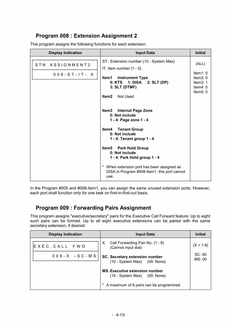
-4-13-
Program 008 : Extension Assignment 2
This program assigns the following functions for each extension.
Display Indication Input Data Initial
S T N # A S S I G N M E N T 2 #
# # # # # 0 0 8 - S T - I T - X
ST. Extension number (10 - System Max)
IT. Item number (1 - 5)
Item1 Instrument Type0: KTS 1: DISA 2: SLT (DP)3: SLT (DTMF)
Item2 Not Used
Item3 Internal Page Zone0: Not include1 - 4: Page zone 1 - 4
Item4 Tenant Group0: Not include1 - 4: Tenant group 1 - 4
Item5 Park Hold Group0: Not include1 - 4: Park Hold group 1 - 4
* When extension port has been assigned asDISA in Program #008-Item1, this port cannotuse.
(ALL)
Item1: 0Item2: 0Item3: 1Item4: 0Item5: 0
In the Program #005 and #008-Item1, you can assign the same unused extension ports. However,each port shall function only for one task on first-in-first-out basis.
Program 009 : Forwarding Pairs Assignment
This program assigns "executive/secretary" pairs for the Executive Call Forward feature. Up to eightsuch pairs can be formed. Up to all eight executive extensions can be paired with the samesecretary extension, if desired.
Display Indication Input Data Initial
E X E C . C A L L # F W D # # #
# # # # # 0 0 9 - X # - S C - M S
X. Call Forwarding Pair No. (1 - 8)(Cannot input dial)
SC. Secretary extension number(10 - System Max) (00: None)
MS. Executive extension number(10 - System Max) (00: None)
* A maximum of 8 pairs can be programmed.
(X = 1-8)
SC: 00MS: 00

-4-14-
Program 010 : Dual Handsfree Hotline
This program assigns "secretary/executive" partnerships for Dual Handsfree Hotline. Up to foursuch partnerships can be assigned.
Display Indication Input Data Initial
D U A L # H F # H O T L I N E #
# # # # 0 0 1 0 - S C - M 1 - M 2
SC. Secretary's extension number(10 - System Max) (00: Not assigned)
M1. Executive 1'st extension number(10 - System Max) (00: Not assigned)
M2. Executive 2'nd extension number(10 - System Max) (00: Not assigned)
* A Maximum of 4 combinations can beprogrammed.
SC: 00M1: 00M2: 00
Program 011 : Hunting Groups
This program assigns extensions to Hunting Groups (0-7) for the Group Hunt and Group HuntTransfer features. Up to Eight Hunting Groups can be formed, with a maximum of sixteenextensions per group.
Display Indication Input Data Initial
H U N T # G R O U P S # # # #
# # # # # # 0 1 1 - N - X X - S T
N. Hunting group number (0 – 7)
XX. Extension No. in pilot group(01 - 16) (Cannot input dial)
ST. Extension number (10 - System Max)(00: None)
* A maximum of 16 extensions can be set in 1Hunting group.
(N = 0-7)(XX = 01-16)
ST: 00

-4-15-
Program 012 : Doorphone Call
This program selects the extensions to receive the chime tones from a Doorphone Box and programthe ring type for each. Up to ten extensions can receive the chimes from both boxes.
Display Indication Input Data Initial
D O O R # C H I M E # B O X #
# # # # # 0 1 2 - N # X X - S T D
N. Doorphone number (1 - 2)
XX. Received extension No. (01 - 10)(Cannot input dial)
ST. Received extension number(10 - System Max) (00: None)
D. Incoming ring type0: No ring 1: Day ring2: Night ring 3: Day and Night ring
* If an extension is selected for Received(on ST) and No ring(on D), extension user can answer to Doorphone call by lift the handset even
extension is not ringing.*A maximum of 10 extensions can be
programmed for each Doorphone.
(N = 1-2)(XX =
01 - 10)
ST: 00D: 0
Program 013 : Extension Assignment 3
This program assigns the following functions for each extension.
Display Indication Input Data Initial
S T N # A S S I G N M E N T 3
# # # # # 0 1 3 - S T - I T - X
ST. Extension number (10 - System Max)
IT. Item number (1 - 5)
Item1 Key Touch Tone0: Enabled 1: Disabled
Item2 Do Not Disturb0: Disabled1: Trunk calls blocked2: Trunk and ICM calls blocked3: Trunk and ICM calls blocked or Trunk
calls blocked.
Item3 Not Used
Item4 Voice Announce Device Port0: Disable 1: Enable
*Assign the Voice Announcing Device port for DISA announcement as auto answering
telephone.
Item5 Terminal Connection (for SLT)0: Not connected 1: Connected
*For KTS, “1” is set automatically when the system is powered up. For SLT, “1” is set when going off-hook for the first time. *If no telephone is connected to extension port, target port should be assigned for “Not connected”. Otherwise intercom caller may get ring back tone if accidentally calls to unconnected port.
(ALL)
Item1: 0Item2: 0Item3: 0Item4: 0Item5: 1

-4-16-
Program 014 : Station Numbering
This program assigns an extension number to a telephone port.
Display Indication Input Data Initial
(Start condition)
F L E X . S T A . # I N G # # #
# # # # # 0 1 4 - 0 0 # # # # # #
∗ Enter the digit setting mode1. Press " ∗ " key.
(Digit setting mode)
F L E X . S T A . # I N G # # #
# # # # # 0 1 4 - 0 0 # # - 0 0 2
∗∗∗∗ Digit set operation1. Dial "00" and "2" or "3".
(2 or 3 digits mode select)2. Press " ∗ " key.
(Return to the start condition)
Digit: 002
(2 digits mode)
F L E X . S T A . # I N G # # #
# # # # # 0 1 4 - S T # # # - S S
ST. Extension number (10 - System Max)
SS. 10 – 69 (2 digits mode)SS: 00 (Not assigned)
SS = ST
(3 digits mode)
F L E X . S T A . # I N G # # #
# # # # # 0 1 4 - S T # # - S S S
SSS. 100 – 699 (3 digits mode)SSS: 000 (Not assigned)
Originally assigned extension numbers in 3 digits mode are 110 to 133. If the customer wants otherextension number within a specific range, extension numbers must be changed by this program.

-4-17-
Program 015 : System Assignment 1
This program selects the functions for the system.
Display Indication Input Data Initial
S Y S # A S S I G N M E N T 1
# # # # # 0 1 5 # # - I T - X
IT. Item number (1 – 5)
Item1 Lamp Shift Mode0: Disable 1: Enable
Item2 Night Service0: All Tenant*If “All Tenant” is selected, all of tenants are
changed to the Night mode at the sametime.
1: Each Tenant*If “Each Tenant” is selected, each tenant can
change to the Night mode individually.
Item3 Automatic Trunk Access0: Disable1: Press SPK key and queuing group No.2: (On-Hook condition) Dial 03: 1 + 2
Item4 Exclusive Hold0: Disable 1: Enable
Item5 Single Step Access0: Disable 1: Enable*When select enable :- Intercom access and seizing trunk can
make by single step.- For Caller-ID, Extension user must press
the “FLASH” key before press the linekey. Otherwise when extension usershow the Caller’s Number, he/she hasbeen answered to incoming call.
*When select disable- Extension user must press “SPK” or lift
the handset before press “ICM” key,when he/she makes intercom call.
- Extension user must press “SPK” or liftthe handset before press “CO” key, whenhe/she seizes trunk call.
- For Caller-ID, Extension user can checkthe Caller’s number, when press the linekey without pressing “FLASH” key.
Item1: 0Item2: 0Item3: 2Item4: 0Item5: 1
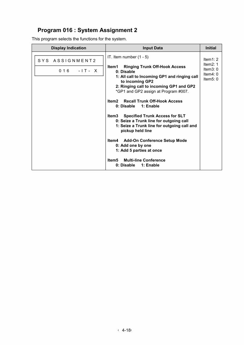
-4-18-
Program 016 : System Assignment 2
This program selects the functions for the system.
Display Indication Input Data Initial
S Y S # A S S I G N M E N T 2 #
# # # # # 0 1 6 # # - I T - X
IT. Item number (1 - 5)
Item1 Ringing Trunk Off-Hook Access0: Disable1: All call to Incoming GP1 and ringing call
to incoming GP22: Ringing call to incoming GP1 and GP2*GP1 and GP2 assign at Program #007.
Item2 Recall Trunk Off-Hook Access0: Disable 1: Enable
Item3 Specified Trunk Access for SLT0: Seize a Trunk line for outgoing call1: Seize a Trunk line for outgoing call and
pickup held line
Item4 Add-On Conference Setup Mode0: Add one by one1: Add 5 parties at once
Item5 Multi-line Conference0: Disable 1: Enable
Item1: 2Item2: 1Item3: 0Item4: 0Item5: 0

-4-19-
Program 017 : System Assignment 3
This program selects the functions for the system.
Display Indication Input Data Initial
S Y S # A S S I G N M E N T 3
# # # # # 0 1 7 # # - I T - X
IT. Item number (1 – 5)
Item1 Dial Pulse Sender Speed0: 10 PPS 1: 20 PPS
Item2 Make/Break Ratio0: 33% 1: 39%
Item3 DTMF Minimum Pause Time0: High-speed (80 ms ON/80 ms OFF)1: Mid-speed (100 ms ON/100 ms OFF)2: Low-speed (150 ms ON/150 ms OFF)3: Continuous
Item4 Storage Quantity of Abbreviated Dial0: 100 1: 200
Item5 Existence offff Attendant for DISA0: None 1: Day2: Night 3: Day and Night
Item1: 0Item2: 0Item3: 0Item4: 0Item5: 1
Program 018 : System Assignment 4
This program selects the functions for the system.
Display Indication Input Data Initial
S Y S # A S S I G N M E N T 4
# # # # # 0 1 8 # # - I T - X
IT. Item number (1 – 5)
Item1 Long Conversation Warning0: Disable 1: Enable
Item2 Caller-ID Message Assignment0: Pattern 1 (OUT OF STATE and
UNAVAILABLE INFO)1: Pattern 2 (OUT OF AREA and PRIVATE)
Item3 Abbreviated Dialing Restriction0: Not restricted*All of extension on Toll Restriction Class 0-4
are allowed to make abbreviated call evenregistered number restricted by Tollrestriction.
1: Restricted*Abbreviated dialing call is restricted
depending on the Toll Restriction Class.
Item4 Handset Receiver Volume0: Reset after conversation1: Keep current volume
Item5 Time Indication0: 12H mode 1: 24H mode
Item1: 0Item2: 0Item3: 0Item4: 0Item5: 0

-4-20-
Program 019 : System Assignment 5
This program selects the functions for the system.
Display Indication Input Data Initial
S Y S # A S S I G N M E N T 5
# # # # # 0 1 9 # # - I T - X
IT. Item number (1 – 5)
Item1 All Call to External Zone0: Disable 1: Enable
Item2 Intercom Call Type0: Voice call 1: Signal call
Item3 Microphone ON/OFF (Initial condition)0: ON 1: OFF
Item4 Room Monitor0: Disable 1: Enable
Item5 SLT Exclusive Hold Release/Attendant Revert Timeout0: Cutoff (Invalid when NVM port isassigned in Program #065).1: Transfer to No.10 Tel or operator extension of each tenant.
Item1: 1Item2: 0Item3: 0Item4: 0Item5: 0
Program 020 : System Assignment 6
This program selects the functions for the system.
Display Indication Input Data Initial
S Y S # A S S I G N M E N T 6
# # # # # 0 2 0 # # - I T - X
IT. Item number (1 – 5)
Item1 Door Chime Tone Duration0: 5 seconds (2 times) 1: 30 seconds
Item2 Paging Splash Tone0: Disable 1: Enable
Item3 Door Alert Tone0: Disable 1: Enable
Item4 Automatic Trunk Access Code forSLT0: Off-Hook and dial 01: Off-Hook and dial 9
Item5 Existence of Doorphone Box0: None1: Doorphone 1 enabled2: Doorphone 2 enabled3: Doorphone 1 and 2 enabled
Item1: 0Item2: 1Item3: 0Item4: 1Item5: 0

-4-21-
Program 021 : Exclusive Hold Recall
This program sets the timer for Exclusive Hold Recall. The timer can be set in 10 second intervals,up to 2550 seconds.
Display Indication Input Data Initial
E X C . H O L D # T I M E R S #
# # # # # 0 2 1 - N # # # - T T T
N. 1: Recall start time2: Recall signal duration time
TTT. Time
000: Not assigned
001 – 255: 10 - 2550 seconds
(N = 1)TTT: 003
(N = 2)TTT = 003
Program 022 : System Hold Recall
This program sets two timers for the System Hold feature:
1. The Recall Timer selects the interval of time a call stays on System Hold before it recalls (re-rings) the extension that placed it on Hold. This timer can be set for 10 second intervals, up to2550 seconds.
2. The Duration Timer determines how long the System Hold Recall signal lasts. The timer can beset for a maximum of 255 seconds.
Display Indication Input Data Initial
S Y S . H O L D # T I M E R S #
# # # # # 0 2 2 - N # # # - T T T
N. 1: Recall Timer2: Duration Timer
TTT. Time001 - 255: 10 - 2550 seconds (N = 1)
1 - 255 seconds (N = 2)
(N = 1)TTT: 006
(N = 2)TTT = 005
Program 023 : Unannounced Transfer Recall
This program determines how long an Unannounced Transfer rings the receiving extension beforerecalling the transferring extension. The timer can be set for multiples of 10 seconds, up to 2550seconds.
Display Indication Input Data Initial
U N A N N . X F E R # T I M E R
# # # # # 0 2 3 # # # # # - T T T
TTT. Recall time000 - 255: 0 - 2550 seconds
TTT: 006
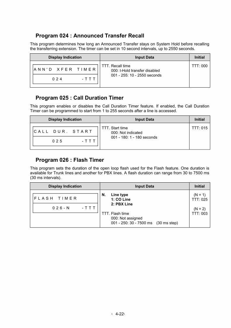
-4-22-
Program 024 : Announced Transfer Recall
This program determines how long an Announced Transfer stays on System Hold before recallingthe transferring extension. The timer can be set in 10 second intervals, up to 2550 seconds.
Display Indication Input Data Initial
A N N ' D # X F E R # T I M E R
# # # # # 0 2 4 # # # # # - T T T
TTT. Recall time000: I-Hold transfer disabled001 - 255: 10 - 2550 seconds
TTT: 000
Program 025 : Call Duration Timer
This program enables or disables the Call Duration Timer feature. If enabled, the Call DurationTimer can be programmed to start from 1 to 255 seconds after a line is accessed.
Display Indication Input Data Initial
C A L L # D U R . # S T A R T #
# # # # # 0 2 5 # # # # # - T T T
TTT. Start time000: Not indicated001 - 180: 1 - 180 seconds
TTT: 015
Program 026 : Flash Timer
This program sets the duration of the open loop flash used for the Flash feature. One duration isavailable for Trunk lines and another for PBX lines. A flash duration can range from 30 to 7500 ms(30 ms intervals).
Display Indication Input Data Initial
F L A S H # T I M E R # # # # #
# # # # # 0 2 6 - N # # # - T T T
N. Line type1: CO Line2: PBX Line
TTT. Flash time000: Not assigned001 - 250: 30 - 7500 ms (30 ms step)
(N = 1)TTT: 025
(N = 2)TTT: 003

-4-23-
Program 027 : SMDR Timers
This program sets two SMDR timers:
1. Call Duration Timer selects the minimum number of seconds (00-60) a call must last in order forit to be recorded on the SMDR printout.
2. Call Start Timer selects the number of seconds (00-60) which pass before SMDR starts timing acall.
Display Indication Input Data Initial
S M D R # T I M E R S # # # # #
# # # # # 0 2 7 # # # # X X - T T
XX. 01: Minimum call duration timer02: Inter-digit timer(01 and 02 cannot input dial)
TT. Time00: Not assigned01 - 60: 1 - 60 seconds
(XX = 01)TT: 00
(XX = 02)TT: 10
Program 028 : Unanswered Timer
This program determines how long an extension rings before transferring a call to other extension(Call Forward when Unanswered). The timer can be set from 1 to 255 seconds.
Display Indication Input Data Initial
D E L A Y # R I N G # T I M E R
# # # # # 0 2 8 # # # # # - T T T
TTT. Time000: Time out disabled001 - 255: 1 - 255 seconds
TTT: 015
Program 029 : Attendant Reverting
This program determines Attendant Revert Timer. A call left on System Hold longer than a thisprogrammed period of time, re-rings the attendant telephone (Extension #10 or operator extensionof each tenant).
Display Indication Input Data Initial
A T T . R E V E R T # T I M E R
# # # # # 0 2 9 # # # # # - T T T
TTT. Attendant revert timer assignment000: Time out disabled001 - 255: 1 - 255 seconds
TTT: 000

-4-24-
Program 030 : Voice Receiver Release Time
This program assigns timer for voice message features.
With DISA, voice messages are sent:
1. Voice message transmission port is not answered automatically after ringing.2. Voice message transmission port is not On-hook after answering automatically.
When this setting time is exceeded, dial tone is heard. (Wait a DTMF dial condition)
Display Indication Input Data Initial
A N N . T I M E R S # # # # # #
# # # # # 0 3 0 - N # # # - T T T
N. 1: Automatic answering timer2: DT (Dial Tone) sending timer
TTT. Timer000: Timeout immediately001 - 255: 1 - 255 seconds
(N = 1)TTT: 030
(N = 2)TTT: 030
Program 031 : Trunk-to-Trunk Release Time
This program assigns a timer for Trunk-to-Trunk conversation cut off.
On setting up Trunk-to-Trunk operation, if a user forget to dial "#" for path connection.
On the Trunk-to-Trunk operation, when conversation is finished, if a user hangs up before dialing “#,# “, and Trunk-to-Trunk condition continues. (1st and 2nd Line keys LED lighting red.) (2)
On the Trunk-to-Trunk conversation, when the warning tone is heard and a user does not dial “1” in10 seconds. (3)
On the (1), (2), and (3) conditions, when the timer elapses, both of 1st and 2nd lines will be cut offautomatically.
Display Indication Input Data Initial
L N . T O # L N . T I M E R S #
# # # # # 0 3 1 - N # # # - T T T
N. 1: Path connection waiting timer2: Warning tone timer for conversation
cut off
TTT. Time000: Time out disabled001 - 255: 1 - 255 seconds (N = 1)
1 - 255 minutes (N = 2)
(N = 1)TTT: 030
(N = 2)TTT: 003
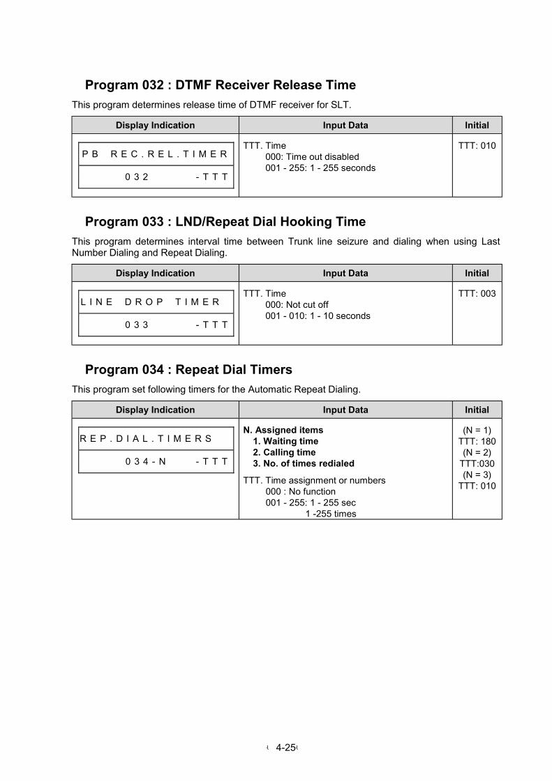
-4-25-
Program 032 : DTMF Receiver Release Time
This program determines release time of DTMF receiver for SLT.
Display Indication Input Data Initial
P B # R E C . R E L . T I M E R
# # # # # 0 3 2 # # # # # - T T T
TTT. Time000: Time out disabled001 - 255: 1 - 255 seconds
TTT: 010
Program 033 : LND/Repeat Dial Hooking Time
This program determines interval time between Trunk line seizure and dialing when using LastNumber Dialing and Repeat Dialing.
Display Indication Input Data Initial
L I N E # D R O P # T I M E R #
# # # # # 0 3 3 # # # # # - T T T
TTT. Time000: Not cut off001 - 010: 1 - 10 seconds
TTT: 003
Program 034 : Repeat Dial Timers
This program set following timers for the Automatic Repeat Dialing.
Display Indication Input Data Initial
R E P . D I A L . T I M E R S # #
# # # # # 0 3 4 - N # # # - T T T
N. Assigned items1. Waiting time2. Calling time3. No. of times redialed
TTT. Time assignment or numbers000 : No function001 - 255: 1 - 255 sec
1 -255 times
(N = 1)TTT: 180(N = 2)
TTT:030(N = 3)
TTT: 010
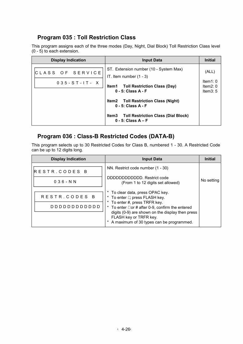
-4-26-
Program 035 : Toll Restriction Class
This program assigns each of the three modes (Day, Night, Dial Block) Toll Restriction Class level(0 - 5) to each extension.
Display Indication Input Data Initial
C L A S S # O F # S E R V I C E
# # # # # 0 3 5 - S T - I T - X
ST. Extension number (10 - System Max)
IT. Item number (1 - 3)
Item1 Toll Restriction Class (Day)0 - 5: Class A - F
Item2 Toll Restriction Class (Night)0 - 5: Class A - F
Item3 Toll Restriction Class (Dial Block)0 - 5: Class A – F
(ALL)
Item1: 0Item2: 0Item3: 5
Program 036 : Class-B Restricted Codes (DATA-B)
This program selects up to 30 Restricted Codes for Class B, numbered 1 - 30. A Restricted Codecan be up to 12 digits long.
Display Indication Input Data Initial
R E S T R . C O D E S B
# # # # # 0 3 6 - N N # # # # # #
R E S T R . C O D E S B
# # # # D D D D D D D D D D D D
NN. Restrict code number (1 - 30)
DDDDDDDDDDDD. Restrict code(From 1 to 12 digits set allowed)
* To clear data, press OPAC key.* To enter ∗ , press FLASH key.* To enter #, press TRFR key.* To enter ∗ or # after 0-9, confirm the entered
digits (0-9) are shown on the display then pressFLASH key or TRFR key.
* A maximum of 30 types can be programmed.
No setting

-4-27-
Program 037 : Permitted Codes (DATA-C)
This program selects up to 40 Permitted Codes, numbered 01 - 40. A Permitted Code can containup to the first 12 digits of the desired telephone number.
Display Indication Input Data Initial
P E R M I T T E D # C O D E S
# # # # # 0 3 7 - N N # # # # # #
P E R M I T T E D # C O D E S
# # # # D D D D D D D D D D D D
NN. Permitted code number (01 - 40)
DDDDDDDDDDDD: Permitted code assignment(From 1 to 12 digits allowed)
* To clear data, press OPAC key.* To enter ∗ , press FLASH key.* To enter #, press TRFR key.* To enter ∗ or # after 0-9, confirm the entered
digits (0-9) are shown on the display then pressFLASH key or TRFR key.
No setting
Program 038 : Number Length Limit(DATA-D1)
This program enables or disables the Permitted Code Digit Limit feature. If enabled, the maximumnumber of digits per Permitted Code call ranges from 1 to 30.
Display Indication Input Data Initial
C O D E # D I G I T # L I M I T
# # # # # # # # 0 3 8 # # # - D D
DD. Digit00: No restriction01 - 30: 1 digit - 30 digits
* A maximum of 30 digits can be programmed.
DD: 00
Program 039 : Class-C/D Restricted Codes (DATA-D2)
This program selects up to 30 Restricted Codes for Class C and D, numbered 1 - 30. A RestrictedCode can be up to 12 digits long.
Display Indication Input Data Initial
R E S T R . C O D E S # D 2
# # # # # 0 3 9 - N N # # # # # #
R E S T R . C O D E S # D 2
# # # # D D D D D D D D D D D D
NN. Restrict code number (1 - 30)
DDDDDDDDDDDD: Restrict code(From 1 to 12 digits set allowed)
* To clear data, press OPAC key.* To enter ∗ , press FLASH key.* To enter #, press TRFR key.* To enter ∗ or # after 0-9, confirm the entered
digits (0-9) are shown on the display then pressFLASH key or TRFR key.
* A maximum of 30 types can be programmed.
No setting
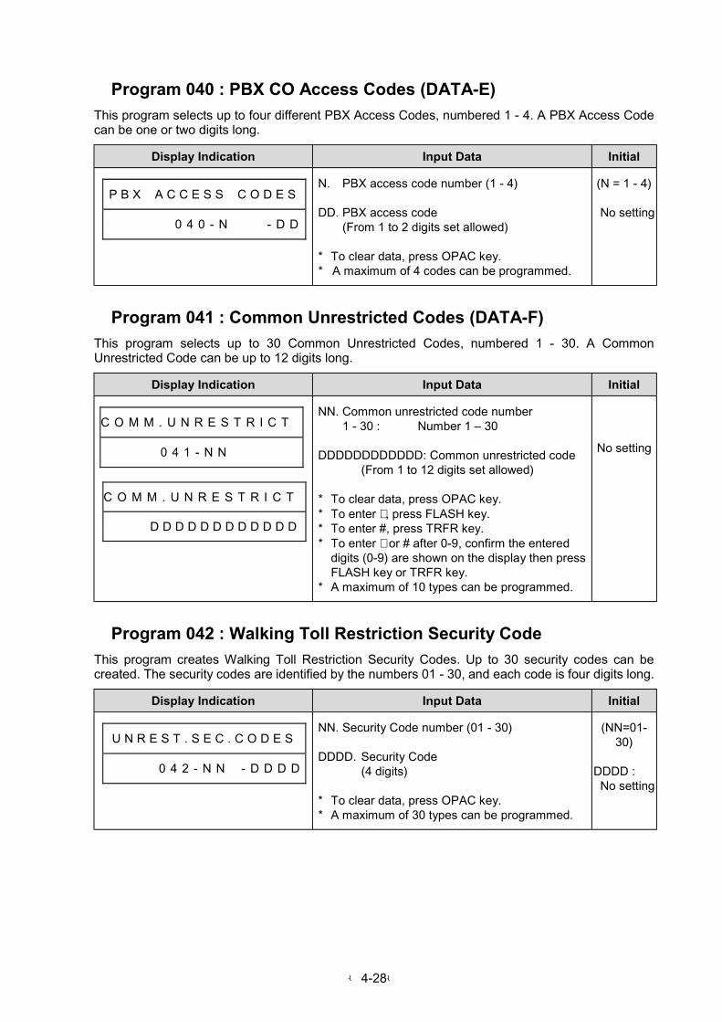
-4-28-
Program 040 : PBX CO Access Codes (DATA-E)
This program selects up to four different PBX Access Codes, numbered 1 - 4. A PBX Access Codecan be one or two digits long.
Display Indication Input Data Initial
P B X # A C C E S S # C O D E S
# # # # # # 0 4 0 - N # # # - D D
N. PBX access code number (1 - 4)
DD. PBX access code(From 1 to 2 digits set allowed)
* To clear data, press OPAC key.* A maximum of 4 codes can be programmed.
(N = 1 - 4)
No setting
Program 041 : Common Unrestricted Codes (DATA-F)
This program selects up to 30 Common Unrestricted Codes, numbered 1 - 30. A CommonUnrestricted Code can be up to 12 digits long.
Display Indication Input Data Initial
C O M M . U N R E S T R I C T
# # # # # 0 4 1 - N N # # # # # #
C O M M . U N R E S T R I C T
# # # # D D D D D D D D D D D D
NN. Common unrestricted code number1 - 30 : Number 1 – 30
DDDDDDDDDDDD: Common unrestricted code(From 1 to 12 digits set allowed)
* To clear data, press OPAC key.* To enter ∗ , press FLASH key.* To enter #, press TRFR key.* To enter ∗ or # after 0-9, confirm the entered
digits (0-9) are shown on the display then pressFLASH key or TRFR key.
* A maximum of 10 types can be programmed.
No setting
Program 042 : Walking Toll Restriction Security Code
This program creates Walking Toll Restriction Security Codes. Up to 30 security codes can becreated. The security codes are identified by the numbers 01 - 30, and each code is four digits long.
Display Indication Input Data Initial
U N R E S T . S E C . C O D E S
# # 0 4 2 - N N # - D D D D
NN. Security Code number (01 - 30)
DDDD. Security Code(4 digits)
* To clear data, press OPAC key.* A maximum of 30 types can be programmed.
(NN=01-30)
DDDD :No setting

-4-29-
Program 043 : Toll Restriction Class Assignment on Security Code
This program assigns restriction class (A to F) to each Walking Toll Restriction Security Code.
Display Indication Input Data Initial
U N R E S T . C L A S S # # # #
# # # # # 0 4 3 - N N # # # # - D
NN. Number (01 - 30)
D. Restriction class0 - 5: Class A - F
* "NN" corresponds to security code in theProgram #042.
* Class shall be defined in Program #035.
(NN=01-30)
D: 0
Program 044 : Not Used
Program 045 : Intercom Link Increase
This program enables or disables the Intercom Link Increase feature.
Display Indication Input Data Initial
I C M # L I N K # I N C R . # #
# # # # # 0 4 5 # # # # # # - D D
DD. Last line number used00: Not assigned01 - System Max minus 1:
Last line number used
* When this System Programming finished, thissystem is reset.
DD: 00
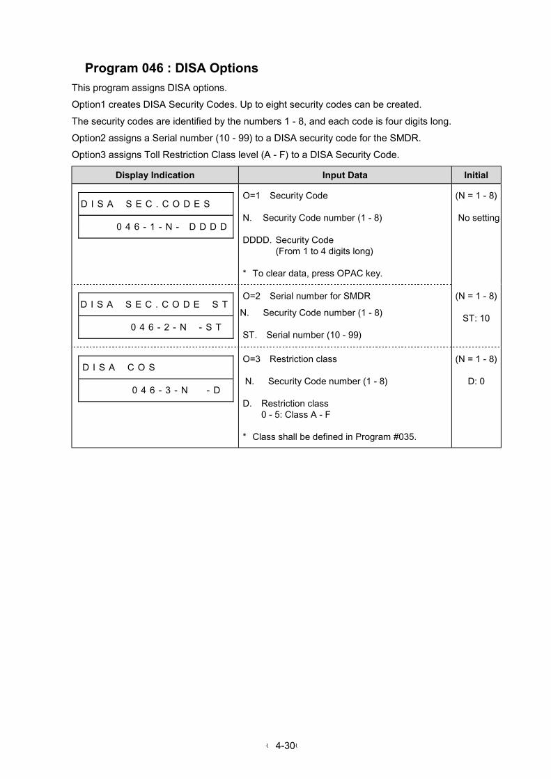
-4-30-
Program 046 : DISA Options
This program assigns DISA options.
Option1 creates DISA Security Codes. Up to eight security codes can be created.
The security codes are identified by the numbers 1 - 8, and each code is four digits long.
Option2 assigns a Serial number (10 - 99) to a DISA security code for the SMDR.
Option3 assigns Toll Restriction Class level (A - F) to a DISA Security Code.
Display Indication Input Data Initial
D I S A # S E C . C O D E S # #
# # # 0 0 4 6 - 1 - N - D D D D
O=1 Security Code
N. Security Code number (1 - 8)
DDDD. Security Code(From 1 to 4 digits long)
* To clear data, press OPAC key.
(N = 1 - 8)
No setting
D I S A # S E C . C O D E # S T
# # # # # 0 4 6 - 2 - N # - S T
O=2 Serial number for SMDR
N. Security Code number (1 - 8)
ST. Serial number (10 - 99)
(N = 1 - 8)
ST: 10
D I S A # C O S # # # # # # # #
# # # # # 0 4 6 - 3 - N # - D
O=3 Restriction class
N. Security Code number (1 - 8)
D. Restriction class0 - 5: Class A - F
* Class shall be defined in Program #035.
(N = 1 - 8)
D: 0

-4-31-
Program 047 : VAU Message Assignment
This program assigns VAU Message Service.
Display Indication Input Data Initial
V A U # M E S S A G E
# # # # # # 0 4 7 - N # # # - D
N. VAU Service Number (1 - 8)
1. 1st DISA Attendant Message
2. 2nd DISA Attendant message
3. DISA Error Message
4. DISA Operator Transfer Message
5. DISA Disconnect Message
6. Automatic Transfer Message
7. 1st Night mode Announcement
8. 2nd Night mode Announcement
D. VAU Message No.(1-4)0: No function1-4: Message number(One message is 15 sec. long.)
(N = 1 - 8)
No setting
Program 048 : Hot Line Timer
This program assigns the Hot line starting time after Off Hook.
Display Indication Input Data Initial
H O T L I N E T I M E R
4 8 4 7 0 4 8 - T T T
TTT. Time000: Immediate Hot Line001 - 255: 1 – 255 seconds
TTT: 000
Program 049 : External Zone BGM
This program assigns Background Music to an external page zone.
* The order of priority : BGM < Trunk Line incoming tone < Paging
Display Indication Input Data Initial
E X T . Z O N E B G M
# # # # # 0 4 9 - X
X. 0: Disable 1: Enable 0

-4-32-
Program 050 : External Zone Trunk AudibleThis program assigns incoming Trunk audible to an external page zone.
Display Indication Input Data Initial
E X T . Z O N E # L N / A U D #
# # # # # 0 5 0 - # # # G P D
GP. Line group00: Not ring01 - 30: Group 01 - Group 30
D. Incoming ring mode0: Not ring 1: Day ring2: Night ring 3: Day and night ring
GP: 00D: 0
Program 051 : Attendant Extension for DISA
This program assigns an attendant extension for DISA.
Display Indication Input Data Initial
A . A . D I V E R T # S T A . #
# # # # # 0 5 1 N N - S T
NN. Day mode/Night mode Assignment
01. Day mode 02. Night mode (Cannot input dial)
ST. Extension number (10 – System Max)
ST: 10
(NN=01-02)
Program 052 : Tenant Feature
This program assigns features for tenant group.
Display Indication Input Data Initial
T E N A N T # O P T I O N # # #
# # # # # 0 5 2 - N # # # # # - D
N. Feature number (1 - 5)1: Intercom call2: Internal paging call3: Common abbreviated dial4: Transfer to attendant5: Not Used
D. Feature access
(N = 1, 2)0: Allowed 1: Restrict
(N = 3)0: Common use1: Assigned abbreviated dial
(N = 4)0: System 1: Each tenant group
(N = 1 - 5)
D: 0
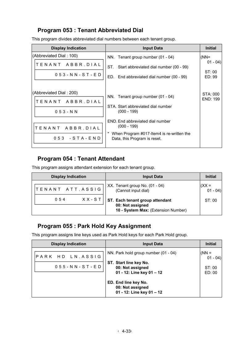
-4-33-
Program 053 : Tenant Abbreviated Dial
This program divides abbreviated dial numbers between each tenant group.
Display Indication Input Data Initial
(Abbreviated Dial : 100)
T E N A N T # A B B R . D I A L
# # # # # 0 5 3 - N N - S T - E D
NN. Tenant group number (01 - 04)
ST. Start abbreviated dial number (00 - 99)
ED. End abbreviated dial number (00 - 99)
(NN=01 - 04)
ST: 00ED: 99
(Abbreviated Dial : 200)
T E N A N T # A B B R . D I A L
# # # # # 0 5 3 - N N # # # # # #
T E N A N T # A B B R . D I A L
# # # # # 0 5 3 # - S T A - E N D
NN. Tenant group number (01 - 04)
STA. Start abbreviated dial number(000 - 199)
END. End abbreviated dial number(000 - 199)
* When Program #017-Item4 is re-written theData, this Program is reset.
STA: 000END: 199
Program 054 : Tenant Attendant
This program assigns attendant extension for each tenant group.
Display Indication Input Data Initial
T E N A N T # A T T . A S S I G
# # # # # 0 5 4 # # # # X X - S T
XX. Tenant group No. (01 - 04)(Cannot input dial)
ST. Each tenant group attendant00: Not assigned10 - System Max: (Extension Number)
(XX =01 - 04)
ST: 00
Program 055 : Park Hold Key Assignment
This program assigns line keys used as Park Hold keys for each Park Hold group.
Display Indication Input Data Initial
P A R K # H D # L N . A S S I G
# # # # # 0 5 5 - N N - S T - E D
NN. Park hold group number (01 - 04)
ST. Start line key No.00: Not assigned01 - 12: Line key 01 – 12
ED. End line key No.00: Not assigned01 - 12: Line key 01 – 12
(NN =01 - 04)
ST: 00ED: 00

-4-34-
Program 056 : Relay Contact Assignment
This program selects a mode of option relay.
Display Indication Input Data Initial
R E L A Y # A S S I G N # # # #
# # # # # 0 5 6 - N # # # # # - D
N. Relay number (1 - 2)
D. Control type0: Not assigned 1: Doorphone 12: Doorphone 2 3: External M.O.H/BGM
(N = 1 - 2)
D: 0
Program 057 : SMDR Assignment
This program selects SMDR option features.
Display Indication Input Data Initial
S M D R # A S S I G N M E N T
# # # # # 0 5 7 - I T - X
IT. Item number (1 - 9)
Item1 Dial Digits (Printout Condition)0: Disable*All of outgoing data is printed out.1: Enable*Outgoing data is printed out, if dialed
number is more than the setting digits whichis assigned on Program#059.
Item2 Outgoing/Incoming Transfer0: Printed 1: Not printed
Item3 No Answer0: Printed 1: Not printed
Item4 Incoming Call0: Print every time1: Print when account code input
Item5 Barred outgoing0: Printed 1: Not printed
Item6 SLT Account Code0: Input enabled 1: Input disabled
Item7 Dialed Number0: Printed 1: Not printed
Item8 Caller-ID data printout0: Not printed 1: Phone No. printed2: Name printed3: Phone No. or Name printed (Name has
priority over Phone No.)
Item9 SMDR Masking digits0: Not Assigned 1-9: Masking digits
Item1: 0Item2: 1Item3: 0Item4: 0Item5: 1
Item6: 1Item7: 1Item8: 0Item9: 0
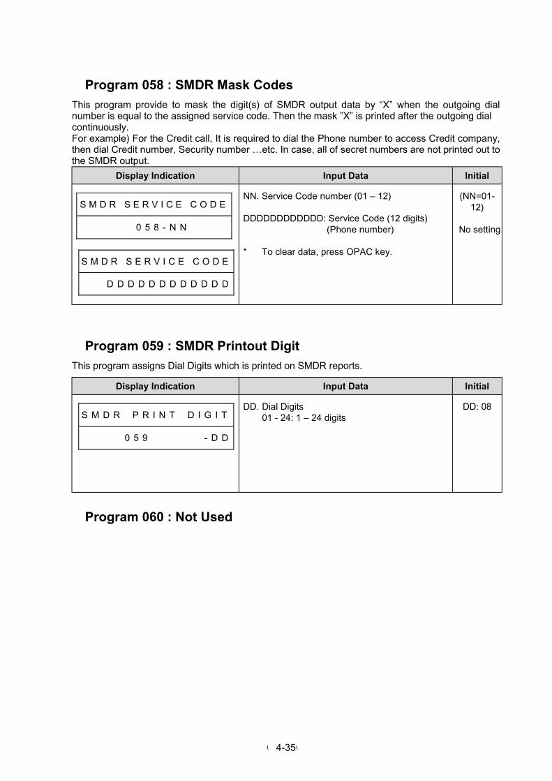
-4-35-
Program 058 : SMDR Mask Codes
This program provide to mask the digit(s) of SMDR output data by “X” when the outgoing dialnumber is equal to the assigned service code. Then the mask ”X” is printed after the outgoing dialcontinuously.For example) For the Credit call, It is required to dial the Phone number to access Credit company,then dial Credit number, Security number …etc. In case, all of secret numbers are not printed out tothe SMDR output.
Display Indication Input Data Initial
S M D R S E R V I C E C O D E
# # # 0 5 8 - N N #
S M D R S E R V I C E C O D E
# # # D D D D D D D D D D D D
NN. Service Code number (01 – 12)
DDDDDDDDDDDD: Service Code (12 digits) (Phone number)
* To clear data, press OPAC key.
(NN=01-12)
No setting
Program 059 : SMDR Printout Digit
This program assigns Dial Digits which is printed on SMDR reports.
Display Indication Input Data Initial
S M D R # P R I N T # D I G I T
# # # # # 0 5 9 # # # # # # - D D
DD. Dial Digits01 - 24: 1 – 24 digits
DD: 08
Program 060 : Not Used

-4-36-
Program 061 : Extension Assignment 4
This program assigns Alpha-numeric keypads, Caller-ID data indication, Caller-ID table editing,SMDR prints outgoing information and Doorphone call/ answer.
Display Indication Input Data Initial
S T N # A S S I G N M E N T 4
# # # # # 0 6 1 - S T - I T - X
ST. Extension Number (10-System max.)
IT. Item number (1 – 9)
Item1 Alpha-numeric key pad assignment0: Pattern1(1st Model Tel)1: Pattern2(ITU-T Rec.E.161) (2nd Model Tel)
Item2 Caller-ID data Indication0: Disable 1: Enable
Item3 Caller-ID table editing0: Disable 1: Enable
Item4 SMDR outgoing information print0: Print 1: No print
Item5 Doorphone call/answer0: Disable 1: Enable
Item6 Call charge SMDR output0: Disable 1: Enable
Item7 -- Not Used --
Item8 -- Not Used –
Item9 -- Not Used --
Item1: 0Item2: 1Item3: 1Item4: 0Item5: 0Item6: 0
Program 062 : Not Used
Program 063 : Not Used

-4-37-
Program 064 : System Assignment 7
This program selects the functions for the system.
Display Indication Input Data Initial
S Y S # A S S I G N M E N T 7
# # # # # 0 6 4 - I T - X
IT. Item number (1 – 9)
Item1 --Not Used--
Item2 Temporary Memory status for Caller-ID0: Not Indicate 1: Indicate
Item3 Automatic Trunk seizing type selection0: Seizing from small number1: Seizing from large number2: Seizing by turns (1→→→→2→→→→3……)
Item4 LED Indication for DISA incoming call0: Busy (Not to answer)1: Normal incoming (O.K. to answer)
Item5 SLT Hooking operation0: Enable 1: Disable
Item6 BGM Check Memory0: Disable 1: Enable
Item7 Paging Path0: Removable 1: Fix
Item8 Serial port(RS232C) Assignment0: Remote Programming 1: SMDR
Item9 --Not Used--
Item1: 0Item2: 0Item3: 0Item4: 0Item5: 0Item6: 0Item7: 0Item8: 0
Program 065 : Voice Mail Port Assignment
This program assigns the extension ports connected to VM (Nitsuko Voice Mail).
Display Indication Input Data Initial
V O I C E M A I L P O R T
# # # # # 0 6 5 # # # # N N - S T
NN. 01 - 08 (Can not input dials)
ST. 00: Not Connected10 - System Max:Extension Port No.
(NN = 01 - 08)
ST: 00

-4-38-
Program 066 : DISA Timers
This program assigns each timer for DISA.
- Item-1 in this program assigns duration time from system detects the incoming call to systemanswers automatically. System can provides ring-back tone to the outside caller by this durationtime.
- Item-2 in this program assigns waiting time for each operation. When this time has passed, thiscall will automatically be transferred to Attendant extension which is assigned in Program #051.
- Item-3 in this program assigns calling time at extension by Extension Access feature. When thistime has passed, this call will automatically be transferred to Attendant extension which isassigned in Program #051.
- Item-5 in this program assigns calling time at Operator extension by Extension Access Feature.- Item5 in this program assigns calling time for operator transfer.
Display Indication Input Data Initial
D I S A # T I M E R S # # # # #
# # # # 0 6 6 - I T # # # - T T T
IT. Item number (1 - 5)
Item1: Automatic answer timeTTT. 000: Answer at once
001 - 255: 1 - 255 sec.
Item2: Dial waiting timeTTT. 001 - 255: 1 - 255 sec.
Item3: Extension calling timeTTT. 001 - 255: 1 - 255 sec.
Item4: Not Used
Item5: Operator calling timeTTT. 001 - 255: 1 - 255 sec.Item5: Operator calling time
TTT. 000: No limitation 001 - 255: 1 - 255 sec
(N = 1)TTT: 000
(N = 2)TTT: 020
(N = 3)TTT: 030
(N = 5)
(N = 5)TTT: 030TTT: 000
Program 074 : Caller-ID Timer
This program assigns Caller-ID signal waiting timer.
- In this program assigns waiting time for Caller-ID signal from PTT.
Display Indication Input Data Initial
C A L L E R - I D # T I M E R S
# # # # # 7 4 - N # # # - T T T
N. 1: Caller-ID signal waiting timer
TTT. 000: Not time out001 - 015: 1 s - 15 s <N = 1>
(N = 1)TTT = 007

-4-39-
Program 075 : Extension Assignment 5
This program assigns Common Abbreviated Area, Automatic Line Seizing by SLT, Key TelephoneOff-Hook Mode Selection, Long Conversation Cutoff, Hot line Mode Selection on an extensionbasis.
Display Indication Input Data Initial
S T N # A S S I G N M E N T 5
# # # # # 0 7 5 - S T - I T - X
ST. Extension number (10-System Max.)
IT. Item number (1 – 9)
Item1 --Not Used--
Item2 Personal Abb. Dial Area Arrangement0: Disable 1: Enable
Item3 SLT Automatic Trunk Access0: Disable 1: Enable
Item4 KTS Off-Hook Mode Selection0: No tone1: Seize Intercom2: Seize idle trunk line
Item5 Long Conversation Cutoff0: Disable 1: Enable
Item6 Hot line Mode Selection0: No function1: Internal Hot line2: External Hot line
Item7 Trunk dialing method (SLT)0: Dial to trunk immediately1: Buffering, then Dial to Trunk
Item8 Fax Port Assignment 0: SLT 1: FAXItem9 -- Not Used --
Item1: 0Item2: 0Item3: 0Item4: 1Item5: 0Item6: 0Item7: 0Item8: 0
(AllExtensions)
Program 077 : Extension Assignment 6
This program determines whether an extension can immediately place a call on hold or the timer inProgram #087 will be followed.
Display Indication Input Data Initial
S T N # A S S I G N M E N T 6
# # # # # 0 7 7 - S T - I T - X
ST. Extension number (10 - System Max.)
IT. Item number (1 - 3)
Item1 Day modeItem2 Night modeItem3 Dial Block mode
0: Can not hold within the timer (#087)1: Can always hold
(No.10 Tel)Item1: 1Item2: 0Item3: 0
(Others)Item1: 0Item2: 0Item3: 0
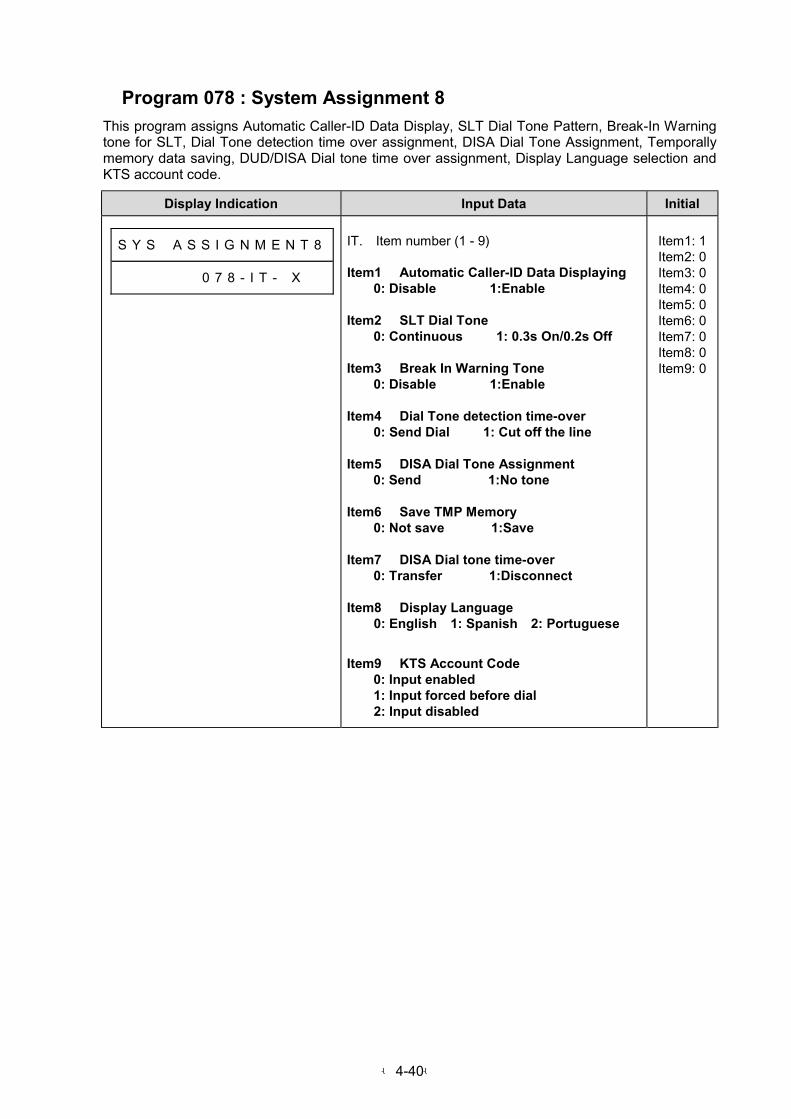
-4-40-
Program 078 : System Assignment 8
This program assigns Automatic Caller-ID Data Display, SLT Dial Tone Pattern, Break-In Warningtone for SLT, Dial Tone detection time over assignment, DISA Dial Tone Assignment, Temporallymemory data saving, DUD/DISA Dial tone time over assignment, Display Language selection andKTS account code.
Display Indication Input Data Initial
S Y S # A S S I G N M E N T 8
# # # # # 0 7 8 - I T - X
IT. Item number (1 - 9)
Item1 Automatic Caller-ID Data Displaying0: Disable 1:Enable
Item2 SLT Dial Tone0: Continuous 1: 0.3s On/0.2s Off
Item3 Break In Warning Tone0: Disable 1:Enable
Item4 Dial Tone detection time-over 0: Send Dial 1: Cut off the line
Item5 DISA Dial Tone Assignment0: Send 1:No tone
Item6 Save TMP Memory0: Not save 1:Save
Item7 DISA Dial tone time-over0: Transfer 1:Disconnect
Item8 Display Language0: English 1: Spanish 2: Portuguese
Item9 KTS Account Code0: Input enabled1: Input forced before dial2: Input disabled
Item1: 1Item2: 0Item3: 0Item4: 0Item5: 0Item6: 0Item7: 0Item8: 0Item9: 0
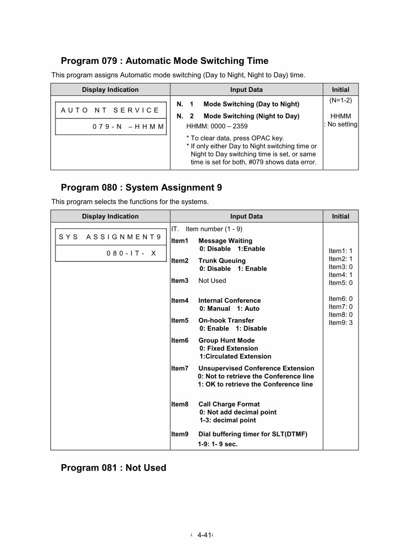
-4-41-
Program 079 : Automatic Mode Switching Time
This program assigns Automatic mode switching (Day to Night, Night to Day) time.
Display Indication Input Data Initial
A U T O N T S E R V I C E
# # # # # 0 7 9 - N – H H M M
N. 1 Mode Switching (Day to Night)
N. 2 Mode Switching (Night to Day)
HHMM: 0000 – 2359
* To clear data, press OPAC key.* If only either Day to Night switching time or
Night to Day switching time is set, or sametime is set for both, #079 shows data error.
(N=1-2)
HHMM: No setting
Program 080 : System Assignment 9
This program selects the functions for the systems.
Display Indication Input Data Initial
S Y S # A S S I G N M E N T 9
0 8 0 - I T - X
IT. Item number (1 - 9)
Item1 Message Waiting0: Disable 1:Enable
Item2 Trunk Queuing0: Disable 1: Enable
Item3 Not Used
Item4 Internal Conference0: Manual 1: Auto
Item5 On-hook Transfer0: Enable 1: Disable
Item6 Group Hunt Mode0: Fixed Extension1:Circulated Extension
Item7 Unsupervised Conference Extension 0: Not to retrieve the Conference line 1: OK to retrieve the Conference line
Item8 Call Charge Format
0: Not add decimal point1-3: decimal point
Item9 Dial buffering timer for SLT(DTMF)
1-9: 1- 9 sec.
Item1: 1Item2: 1Item3: 0Item4: 1Item5: 0
Item6: 0Item7: 0Item8: 0Item9: 3
Program 081 : Not Used
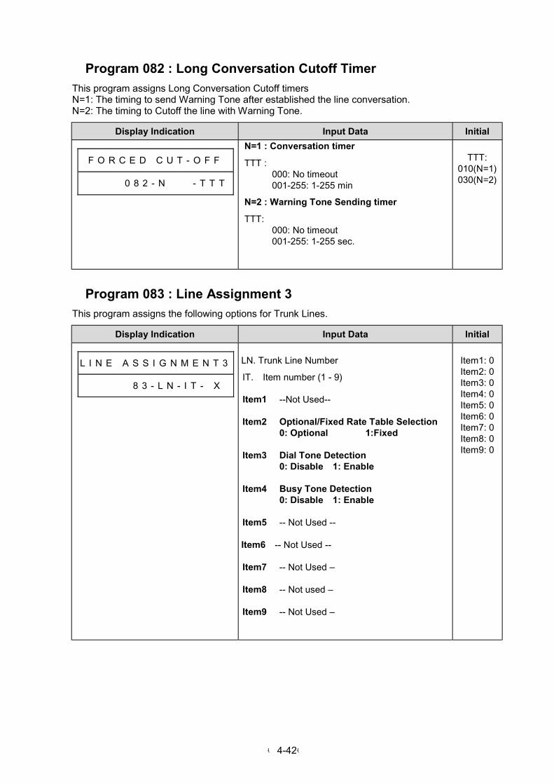
-4-42-
Program 082 : Long Conversation Cutoff Timer
This program assigns Long Conversation Cutoff timersN=1: The timing to send Warning Tone after established the line conversation.N=2: The timing to Cutoff the line with Warning Tone.
Display Indication Input Data Initial
F O R C E D C U T - O F F
# # # 8 0 8 2 - N - T T T
N=1 : Conversation timer
TTT :000: No timeout001-255: 1-255 min
N=2 : Warning Tone Sending timer
TTT:000: No timeout001-255: 1-255 sec.
TTT:010(N=1)030(N=2)
Program 083 : Line Assignment 3
This program assigns the following options for Trunk Lines.
Display Indication Input Data Initial
L I N E A S S I G N M E N T 3
# # # # # 8 3 - L N - I T - X
LN. Trunk Line Number
IT. Item number (1 - 9)
Item1 --Not Used--
Item2 Optional/Fixed Rate Table Selection0: Optional 1:Fixed
Item3 Dial Tone Detection0: Disable 1: Enable
Item4 Busy Tone Detection0: Disable 1: Enable
Item5 -- Not Used --
Item6 -- Not Used --
Item7 -- Not Used –
Item8 -- Not used –
Item9 -- Not Used –
Item1: 0Item2: 0Item3: 0Item4: 0Item5: 0Item6: 0Item7: 0Item8: 0Item9: 0

-4-43-
Program 084 : Group Hunt Calling Timer
This program assigns Group Hunt Calling Timer.
Display Indication Input Data Initial
H U N T # C A L L T I M E R
# # # # # 0 8 4 # # # # # - T T T
TTT. Group Hunt Calling Timer000: Not call other extension
001 - 255: 1 - 255 sec.
TTT: 015
Program 085 : Not Used
Program 086 : Dial Tone Detection Timer
This program determines the researched and disconnect time for Dial Tone Detection.
Display Indication Input Data Initial
D T D T I M E R S
# # # # # 0 8 6 - N # # - T T T
N. 1: Researched Timer2: Disconnect time when Dial Tone is notdetected
TTT Timer000: Disable001-255: 1-255 sec.
(N=1)
TTT: 005
(N=2)
TTT:000
Program 087 : Hold Disable Timer
This program determines how long after seizing a Trunk line a user must wait before the line can beplaced on hold.
Display Indication Input Data Initial
H D D I S A B L E T I M E R
# # # # # 0 8 7 # # # # # - T T T
TTT. Hold Disable Timer000: Can hold immediately001 - 255: 1 - 255 s
TTT: 000
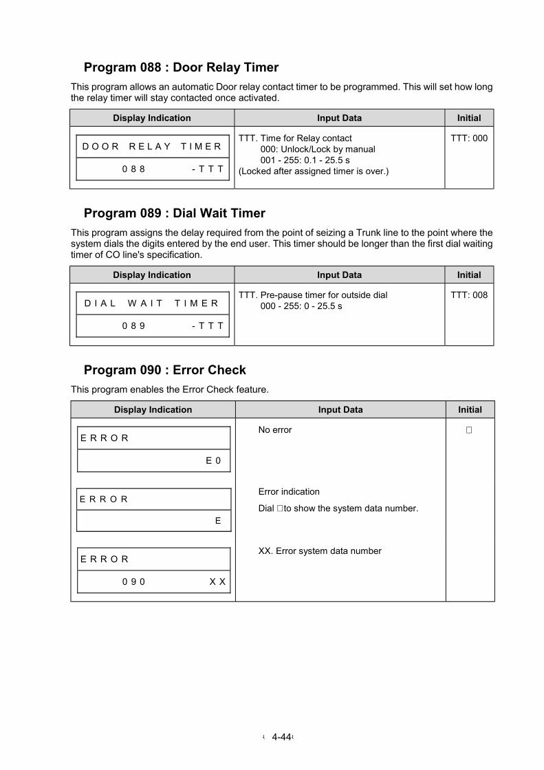
-4-44-
Program 088 : Door Relay Timer
This program allows an automatic Door relay contact timer to be programmed. This will set how longthe relay timer will stay contacted once activated.
Display Indication Input Data Initial
D O O R # R E L A Y # T I M E R
# # # # # 0 8 8 # # # # # - T T T
TTT. Time for Relay contact000: Unlock/Lock by manual001 - 255: 0.1 - 25.5 s
(Locked after assigned timer is over.)
TTT: 000
Program 089 : Dial Wait Timer
This program assigns the delay required from the point of seizing a Trunk line to the point where thesystem dials the digits entered by the end user. This timer should be longer than the first dial waitingtimer of CO line's specification.
Display Indication Input Data Initial
D I A L # W A I T # T I M E R
# # # # # 0 8 9 # # # # # - T T T
TTT. Pre-pause timer for outside dial000 - 255: 0 - 25.5 s
TTT: 008
Program 090 : Error Check
This program enables the Error Check feature.
Display Indication Input Data Initial
E R R O R # # # # # # # # # # #
# # # # # # # # # # # # # # E 0
No error
E R R O R # # # # # # # # # # #
# # # # # # # # # # # # # # # E
Error indication
Dial ∗ to show the system data number.
E R R O R # # # # # # # # # # #
# # # # # 0 9 0 # # # # # # # X X
XX. Error system data number
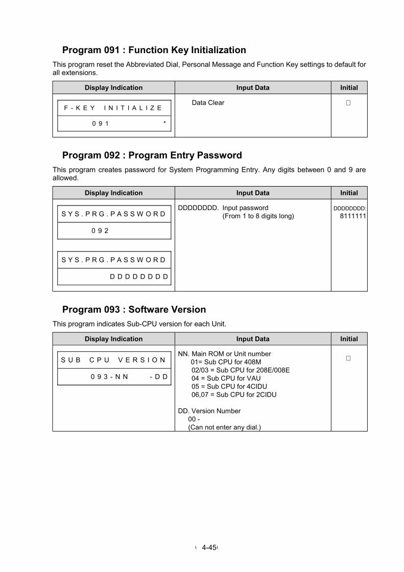
-4-45-
Program 091 : Function Key Initialization
This program reset the Abbreviated Dial, Personal Message and Function Key settings to default forall extensions.
Display Indication Input Data Initial
F - K E Y # I N I T I A L I Z E
# # # # # 0 9 1 # # # # # # # # *
Data Clear
Program 092 : Program Entry Password
This program creates password for System Programming Entry. Any digits between 0 and 9 areallowed.
Display Indication Input Data Initial
S Y S . P R G . P A S S W O R D
# # # # # 0 9 2 # # # # # # # # #
S Y S . P R G . P A S S W O R D
# # # # # # # # D D D D D D D D
DDDDDDDD. Input password(From 1 to 8 digits long)
DDDDDDDD:
8111111
Program 093 : Software Version
This program indicates Sub-CPU version for each Unit.
Display Indication Input Data Initial
S U B # C P U # V E R S I O N
# # # # # 0 9 3 - N N # # # - D D
NN. Main ROM or Unit number01= Sub CPU for 408M02/03 = Sub CPU for 208E/008E04 = Sub CPU for VAU05 = Sub CPU for 4CIDU06,07 = Sub CPU for 2CIDU
DD. Version Number 00 - (Can not enter any dial.)
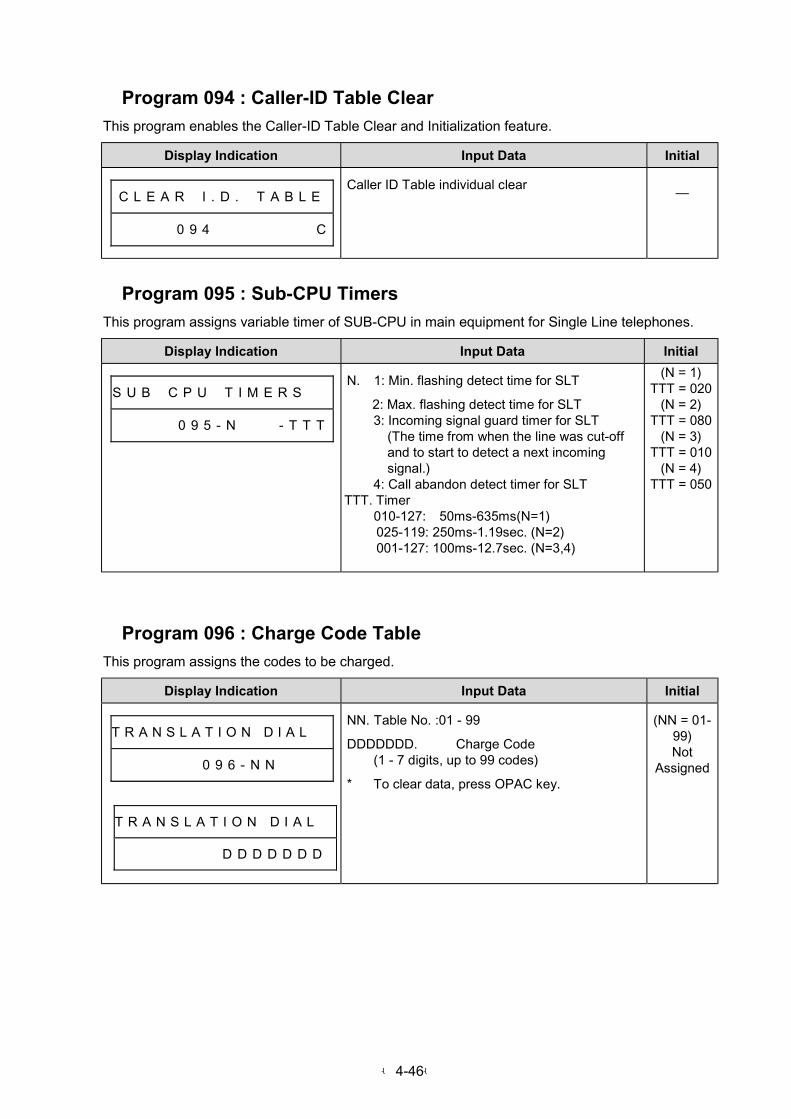
-4-46-
Program 094 : Caller-ID Table Clear
This program enables the Caller-ID Table Clear and Initialization feature.
Display Indication Input Data Initial
C L E A R # I . D . # T A B L E
# # # # # 0 9 4 # # # # # # # # C
Caller ID Table individual clear—
Program 095 : Sub-CPU Timers
This program assigns variable timer of SUB-CPU in main equipment for Single Line telephones.
Display Indication Input Data Initial
S U B # C P U # T I M E R S # #
# # # # # 0 9 5 - N # # # - T T T
N. 1: Min. flashing detect time for SLT
2: Max. flashing detect time for SLT3: Incoming signal guard timer for SLT
(The time from when the line was cut-offand to start to detect a next incomingsignal.)
4: Call abandon detect timer for SLTTTT. Timer
010-127: 50ms-635ms(N=1) 025-119: 250ms-1.19sec. (N=2) 001-127: 100ms-12.7sec. (N=3,4)
(N = 1)TTT = 020
(N = 2)TTT = 080
(N = 3)TTT = 010
(N = 4)TTT = 050
Program 096 : Charge Code Table
This program assigns the codes to be charged.
Display Indication Input Data Initial
T R A N S L A T I O N D I A L #
# # # 0 9 6 - N N
T R A N S L A T I O N D I A L #
# # # # # D D D D D D D
NN. Table No. :01 - 99
DDDDDDD. Charge Code(1 - 7 digits, up to 99 codes)
* To clear data, press OPAC key.
(NN = 01-99)Not
Assigned
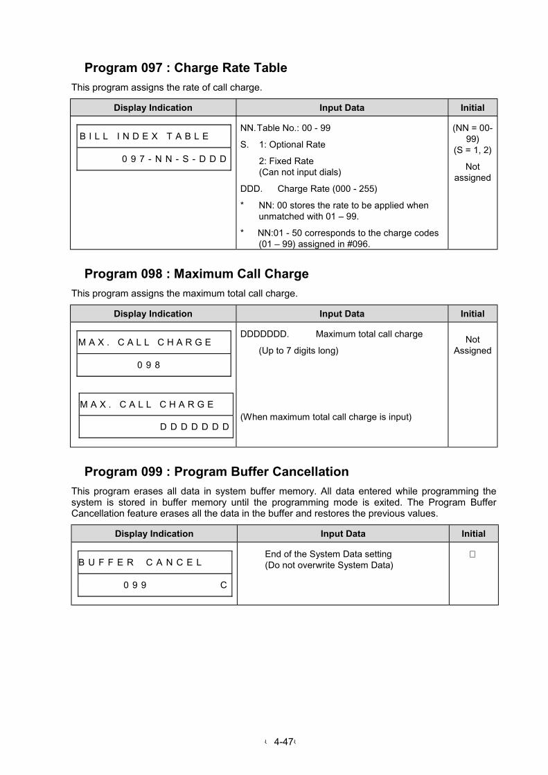
-4-47-
Program 097 : Charge Rate Table
This program assigns the rate of call charge.
Display Indication Input Data Initial
B I L L I N D E X T A B L E # #
# # # # # 0 9 7 - N N - S - D D D
NN. Table No.: 00 - 99
S. 1: Optional Rate
2: Fixed Rate(Can not input dials)
DDD. Charge Rate (000 - 255)
* NN: 00 stores the rate to be applied whenunmatched with 01 – 99.
* NN:01 - 50 corresponds to the charge codes(01 – 99) assigned in #096.
(NN = 00-99)
(S = 1, 2)
Notassigned
Program 098 : Maximum Call Charge
This program assigns the maximum total call charge.
Display Indication Input Data Initial
M A X . C A L L C H A R G E # #
0 9 8
M A X . C A L L C H A R G E # #
D D D D D D D
DDDDDDD. Maximum total call charge
(Up to 7 digits long)
(When maximum total call charge is input)
NotAssigned
Program 099 : Program Buffer Cancellation
This program erases all data in system buffer memory. All data entered while programming thesystem is stored in buffer memory until the programming mode is exited. The Program BufferCancellation feature erases all the data in the buffer and restores the previous values.
Display Indication Input Data Initial
B U F F E R # C A N C E L # # #
# # # # # 0 9 9 # # # # # # # # C
End of the System Data setting(Do not overwrite System Data)
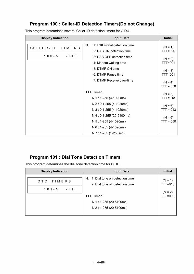
-4-48-
Program 100 : Caller-ID Detection Timers(Do not Change)
This program determines several Caller-ID detection timers for CIDU.
Display Indication Input Data Initial
C A L L E R - I D # T I M E R S
# # # # 1 0 0 - N # # - T T T
N. 1: FSK signal detection time
2: CAS ON detection time
3: CAS OFF detection time
4: Modem waiting time
5: DTMF ON time
6: DTMF Pause time
7: DTMF Receive over-time
TTT. Timer :
N.1 : 1-255 (4-1020ms)
N.2 : 0,1-255 (4-1020ms)
N.3 : 0,1-255 (4-1020ms)
N.4 : 0,1-255 (20-5100ms)
N.5 : 1-255 (4-1020ms)
N.6 : 1-255 (4-1020ms)
N.7 : 1-255 (1-255sec)
(N = 1)TTT=025
(N = 2)TTT=001
(N = 3)TTT=001
(N = 4)TTT = 050
(N = 5)TTT=013
(N = 6)TTT = 013
(N = 6)TTT = 050
Program 101 : Dial Tone Detection Timers
This program determines the dial tone detection time for CIDU.
Display Indication Input Data Initial
D T D # T I M E R S
# # # # 1 0 1 - N # # - T T T
N. 1: Dial tone on detection time
2: Dial tone off detection time
TTT. Timer :
N.1 : 1-255 (20-5100ms)
N.2 : 1-255 (20-5100ms)
(N = 1)TTT=010
(N = 2)TTT=008

-4-49-
Program 102 : One Cycle Time for Tone Detection
This program determines the min./max. one cycle time for Tone Detection.
Display Indication Input Data Initial
O N E C Y C L E # T I M E
# # # # 1 0 2 - T - N # - T T T
T. Tone Type
1: Ring Back Tone
2: Busy Tone
3: 2nd Dial tone
N. 1: Min. one cycle time
2: Max. one cycle time
TTT. Timer : 0,1-255 (20-5100ms)
(T.=1)N.1=132N.2=167
(T.=2)N.1=132N.2=167
(T.=3)N.1=042N.2=057
Program 103 : Tone On/Off time for Tone Detection
This program determines the tone on/off time for Tone Detection.
Display Indication Input Data Initial
T O N E O N / O F F T I M E
# # # # 1 0 3 - T - N # - T T T
T. Tone Type
1: Ring Back Tone
2: Busy Tone
3: 2nd Dial tone
N. 1:1st Min. tone on time
2: 1st Max. tone on time
3: 1st Min. tone off time
4: 1st Max. tone off time
5: 2nd Min. tone on time
6: 2nd Max. tone on time
7: 2nd Min. tone off time
8: 2nd Max. tone off time
TTT. Timer : 0,1-255 (20-5100ms)
(T.=1)N.1=042N.2=057N.3=087N.4=112N.5=000N.6=000N.7=000N.8=000
(T.=2)N.1=020N.2=029N.3=020N.4=029N.5=000N.6=000N.7=000N.8=000
(T.=3)N.1=003N.2=008N.3=003N.4=008N.5=000N.6=000N.7=000N.8=000

-4-50-
Program 104 : Tone On/Off count for Tone Detection
This program determines the tone on/off count value for Tone Detection.
Display Indication Input Data Initial
T - O N / O F F C O U N T
# # # # 1 0 4 - T - # C C C
T. Tone Type
1: Ring Back Tone
2: Busy Tone
3: 2nd Dial tone
CCC. Count : 0-255
T=1: 1T=2: 3T=3: 4
Program 105 : DTMF Tone On/Off Detection Time (Do not Change)
This program determines the DTMF tone detection time for CIDU.
Display Indication Input Data Initial
D T M F O N / O F F # T I M E
# # # # 1 0 5 - N # # - T T T
N. 1: DTMF tone on detection time
2: DTMF tone off detection time
TTT. Timer :
N.1 : 1-255 (4-1020ms)
N.2 : 1-255 (4-1020ms)
(N = 1)TTT=005
(N = 2)TTT=005
Program 106 : Hot Line Destination Number
This program defines the Hot Line destination number for each station port.
Display Indication Input Data Initial
H O T L I N E N U M B E R
# # # 1 0 6 - S T #
H O T L I N E N U M B E R
D D D D D D D D D D D D D
ST. Station number (10-System Max.)
DDDDDDDDDDDDDDDD: Destination Number(Up to 16 digits)
* To clear data, press OPAC key.
(Allstations)
No setting
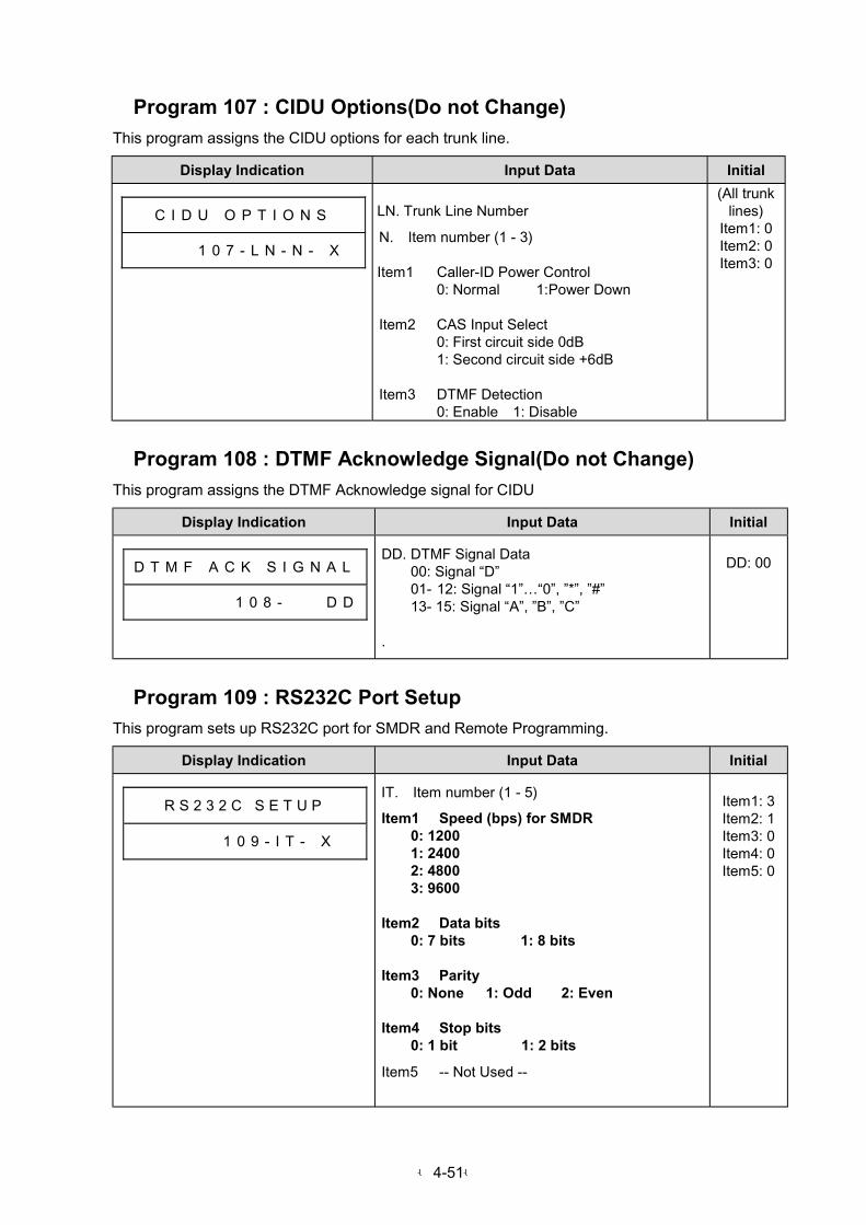
-4-51-
Program 107 : CIDU Options(Do not Change)
This program assigns the CIDU options for each trunk line.
Display Indication Input Data Initial
C I D U O P T I O N S
# # # # 1 0 7 - L N - N - X
LN. Trunk Line Number
N. Item number (1 - 3)
Item1 Caller-ID Power Control0: Normal 1:Power Down
Item2 CAS Input Select0: First circuit side 0dB1: Second circuit side +6dB
Item3 DTMF Detection0: Enable 1: Disable
(All trunklines)
Item1: 0Item2: 0Item3: 0
Program 108 : DTMF Acknowledge Signal(Do not Change)
This program assigns the DTMF Acknowledge signal for CIDU
Display Indication Input Data Initial
D T M F A C K S I G N A L
# # # # 1 0 8 - D D
DD. DTMF Signal Data00: Signal “D”01- 12: Signal “1”…“0”, ”*”, ”#”13- 15: Signal “A”, ”B”, ”C”
.
DD: 00
Program 109 : RS232C Port Setup
This program sets up RS232C port for SMDR and Remote Programming.
Display Indication Input Data Initial
R S 2 3 2 C S E T U P
# # # # # 1 0 9 - I T - X
IT. Item number (1 - 5)
Item1 Speed (bps) for SMDR0: 12001: 24002: 48003: 9600
Item2 Data bits0: 7 bits 1: 8 bits
Item3 Parity0: None 1: Odd 2: Even
Item4 Stop bits0: 1 bit 1: 2 bits
Item5 -- Not Used --
Item1: 3Item2: 1Item3: 0Item4: 0Item5: 0

-4-52-
Program 110 : Transmit Level Attenuation for MODEMU
This program sets up the transmit level attenuation for MODEMU.
Display Indication Input Data Initial
M O D E M L E V E L
# # # # # 1 1 0 - X
X. Transmit Level Attenuation
0: 0 dB attenuation1: 2 dB attenuation2: 4 dB attenuation3: 6 dB attenuation4: 8 dB attenuation5: 10 dB attenuation6: 12 dB attenuation7: 14 dB attenuation
5(10dBatten.)
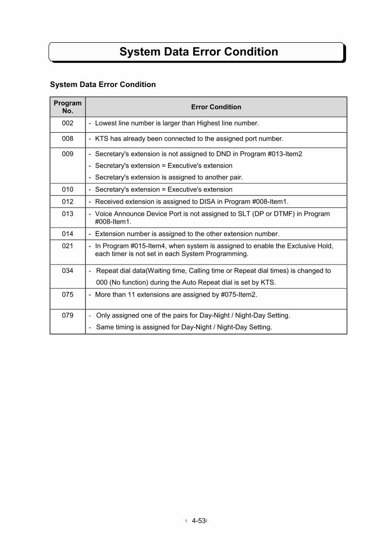
-4-53-
System Data Error Condition
System Data Error Condition
ProgramNo.
Error Condition
002 - Lowest line number is larger than Highest line number.
008 - KTS has already been connected to the assigned port number.
009 - Secretary's extension is not assigned to DND in Program #013-Item2
- Secretary's extension = Executive's extension
- Secretary's extension is assigned to another pair.
010 - Secretary's extension = Executive's extension
012 - Received extension is assigned to DISA in Program #008-Item1.
013 - Voice Announce Device Port is not assigned to SLT (DP or DTMF) in Program#008-Item1.
014 - Extension number is assigned to the other extension number.
021 - In Program #015-Item4, when system is assigned to enable the Exclusive Hold,each timer is not set in each System Programming.
034 - Repeat dial data(Waiting time, Calling time or Repeat dial times) is changed to
000 (No function) during the Auto Repeat dial is set by KTS.
075 - More than 11 extensions are assigned by #075-Item2.
079 - Only assigned one of the pairs for Day-Night / Night-Day Setting.
- Same timing is assigned for Day-Night / Night-Day Setting.
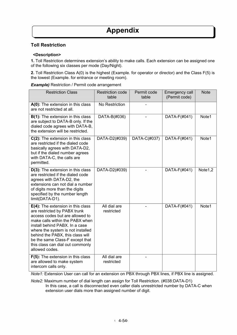
-4-54-
Appendix
Toll Restriction
<Description>
1. Toll Restriction determines extension’s ability to make calls. Each extension can be assigned oneof the following six classes per mode (Day/Night).
2. Toll Restriction Class A(0) is the highest (Example. for operator or director) and the Class F(5) isthe lowest (Example. for entrance or meeting room).
Example) Restriction / Permit code arrangement
Restriction Class Restriction codetable
Permit codetable
Emergency call(Permit code)
Note
A(0): The extension in this classare not restricted at all.
No Restriction -
B(1): The extension in this classare subject to DATA-B only. If thedialed code agrees with DATA-B,the extension will be restricted.
DATA-B(#036) - DATA-F(#041) Note1
C(2): The extension in this classare restricted if the dialed codebasically agrees with DATA-D2,but if the dialed number agreeswith DATA-C, the calls arepermitted.
DATA-D2(#039) DATA-C(#037) DATA-F(#041) Note1
D(3): The extension in this classare restricted if the dialed codeagrees with DATA-D2, theextensions can not dial a numberof digits more than the digitsspecified by the number lengthlimit(DATA-D1).
DATA-D2(#039) - DATA-F(#041) Note1,2
E(4): The extension in this classare restricted by PABX trunkaccess codes but are allowed tomake calls within the PABX wheninstall behind PABX. In a casewhere the system is not installedbehind the PABX, this class willbe the same Class-F except thatthis class can dial out commonlyallowed codes.
All dial arerestricted
- DATA-F(#041) Note1
F(5): The extension in this classare allowed to make systemintercom calls only.
All dial arerestricted
-
Note1: Extension User can call for an extension on PBX through PBX lines, if PBX line is assigned.
Note2: Maximum number of dial length can assign for Toll Restriction. (#038:DATA-D1) In this case, a call is disconnected even caller dials unrestricted number by DATA-C when extension user dials more than assigned number of digit.

-4-55-
Appendix3. The DATA(restricted/permitted codes and number length limit) within the Classes must beentered in System Program.
4. Toll Restriction is not applied to lines programmed as unrestricted lines.
5. When the system is placed in night mode by Night Service feature, the Toll Restriction Classassignment for night mode is activated.
6. Restriction code
If the first digit of dialed number for outgoing call is not matched with restriction code (DATA-B orDATA-D2), then the call is established. However if dialed number matched with restriction code, thecall is terminated.
Example) Restriction code : 0123 1) Dialed number: 10123 !!!! O.K. (The call is established) 2) Dialed number: 01231 !!!! N.G. (The call is Terminated)7. Permit code
This is special code to allows an extension user can call even it is restricted by restriction code
Example) Restriction code : 0, Permitted code : 01201) Dialed number: 011 !!!! N.G. (The call is Terminated)2) Dialed number: 0120 !!!! O.K. (The call is established)3) Dialed number: 0122 !!!! N.G. (The call is Terminated)
8. Planning Example for Toll Restriction
RestrictionClass
Class of person Which dial should be restricted? Which dial should bepermitted?
A(0) Director or
Operator
" No restriction " This class can call toanywhere in the world.
" Intercom call
B(1) General Manager " International access (00) " This class can call toanywhere in the country.
" Intercom call
C(2) Manager " International access (00)" Long distance code (0)
" Hand-phone(070,090)" Pager(060)" City call(1-9)" Emergency call
(110,119,0120)" Intercom call
D(3) Staff " International access (00)" Long distance code (0)" Hand-phone and
pager(070,090)
" City call(1-9)" Emergency call
(110,119,0120)" Intercom call
E(4) Assistant guardhouse
" International access (00)" Long distance code (0)" Hand-phone and
pager(070,090)" City call(1-9)
" Emergency call(110,119,0120)
" Intercom call
F(5) Reception orMeeting room
" All of number " Intercom call only
This is just for example. All of above number are depends on the Local Telephone Company.
Above combination can be modified by programming.

PART 5
OPTIONAL ITEMS
5-1: Caller-ID Unit
5-2: Voice Announce Unit
5-3: System Up Grade(ROMU)

PART 5-1
Caller-ID Unit
Table of Contents
General Description ..................................................................................................................5-1-1
Required Items & Capacity .......................................................................................................5-1-1
Installation of CIDU-M1 Unit ....................................................................................................5-1-2
Display Indication for Caller-ID Information..............................................................................5-1-4
Caller-ID Table........................................................................................................................5-1-10
Temporary Memory.................................................................................................................5-1-23
SMDR Printout ........................................................................................................................5-1-26
Feature Access Keys..............................................................................................................5-1-26
List of Display Information ......................................................................................................5-1-28
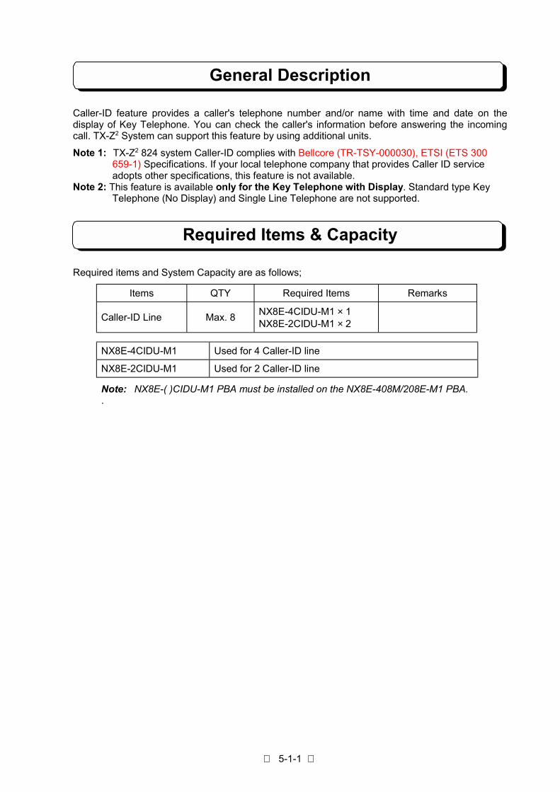
5-1-1
General Description
Caller-ID feature provides a caller's telephone number and/or name with time and date on thedisplay of Key Telephone. You can check the caller's information before answering the incomingcall. TX-Z2 System can support this feature by using additional units.
Note 1: TX-Z2 824 system Caller-ID complies with Bellcore (TR-TSY-000030), ETSI (ETS 300 659-1) Specifications. If your local telephone company that provides Caller ID service adopts other specifications, this feature is not available.Note 2: This feature is available only for the Key Telephone with Display. Standard type Key Telephone (No Display) and Single Line Telephone are not supported.
Required Items & Capacity
Required items and System Capacity are as follows;
Items QTY Required Items Remarks
Caller-ID Line Max. 8NX8E-4CIDU-M1 × 1NX8E-2CIDU-M1 × 2
NX8E-4CIDU-M1 Used for 4 Caller-ID line
NX8E-2CIDU-M1 Used for 2 Caller-ID line
Note: NX8E-( )CIDU-M1 PBA must be installed on the NX8E-408M/208E-M1 PBA..

5-1-2
Installation of CIDU-M1 Unit
! Open the upper housing of main equipmentStep 1: Power Switch must be turn off.Step 2: Loosen the two screws and remove the upper housing.
! Installation of 4CIDU-M1 UnitTo install 4CIDU-M1 Unit in the Main Equipment
Step 1: Attach the two Nylon Spacer (included) to the holes on the Base Unit(408M-M1).Step 2: Attach the 4CIDU Unit to the connector labeled CIDCN and Nylon Spacer on the Base Unit.
Step 3: Put the Housing and cover back and secure the screws.
ETH2
NX8E-408M-M1
NX8E-4CIDU-M1
CIDCN
ETH1
Nylon Spacer

5-1-3
Installation of CIDU-M1 Unit
! Installation of 2CIDU-M1 Unit To install 2CIDU-M1 Unit in the Main Equipment
Step 1: Attach the two Nylon Spacer (included) to the holes on the Base Unit(208E-M1).Step 2: Attach the 2CIDU Unit to the connector labeled CIDCN and Nylon Spacer on the Base Unit.
Step 3: Put the Housing and cover back and secure the screws.
ETH2 NX8E-408M-M1
NX8E-208E-M1ETH
NX8E-2CIDU-M1CID
CN
Nylon Spacer

5-1-4
Display Indication for Caller-ID Information
[ DESCRIPTION ]
When the system receives an incoming call, a line key on the Key Telephone indicates busy status.Then indication of line key will be changed to incoming status after receiving Caller-ID informationfrom a PTT's line and display of the Key Telephone sets indicates the Caller Number (and/or Name)then user can answer the call.
If a Caller-ID information is not received within preset time, a line key associated with incoming callindicates normal incoming status and Key Telephone user can answer the call normally.
[ OPERATION ]
1. To show the Caller-ID information at the ringing extension.1) When Caller-ID information is received (Caller's Name Information: Exist)
Display Indication Operation and Information
# # S U N # 2 5 # 1 2 : 0 0 P M
1 0 # # # # # # # # # # # # # #
(On-Hook condition)
X X X X X X X X X X X X X X X X
Y Y Y Y Y Y Y Y Y Y Y Y Y Y Y #
1. While incoming call is being received.
* Display status can not be changed by pressing CHECKkey.
N O # N U M B E R # I N F O #
Y Y Y Y Y Y Y Y Y Y Y Y Y Y Y
2. If caller's Telephone Number has no information, thedisplay will be indicated as shown;
Note: Indication contents are as follows;XXXXXXXXXXXXXXXX: Caller's Telephone Number (Maximum 16 digits)YYYYYYYYYYYYYYY: Caller's Name (Maximum 15 digits)

5-1-5
Display Indication for Caller-ID Information
2) When Caller-ID information is received (Caller's Name Information: Not Exist)
Display Indication Operation and Information
# # S U N # 2 5 # 1 2 : 0 0 P M
1 0 # # # # # # # # # # # # # #
(On-Hook condition)
X X X X X X X X X X X X X X X X
H H : M M # D D / M M / Y Y # #
1. While incoming call is being received.
N O # N U M B E R # I N F O #
H H : M M # D D / M M / Y Y # #
2. If caller's Telephone Number has no information, thedisplay will be indicated as shown;
Note: Indication contents are as follows;XXXXXXXXXXXXXXXX: Caller's Telephone Number (Maximum 16 digits)HH:MM: TimeDD/MM/YY: Day/Month/Year
3) When Caller-ID information is not received
Display Indication Operation and Information
# # S U N # 2 5 # 1 2 : 0 0 P M
1 0 # # # # # # # # # # # # # #
(On-Hook condition)
L I N E # X X # # # # # # # # #
N O # C A L L E R # I N F O # #
1. While incoming call is being received.
Note: Indication contents are as follows;XX: Line Number

5-1-6
Display Indication for Caller-ID Information
4) When caller calls from Non Caller-ID Service Area
Display Indication Operation and Information
# # S U N # 2 5 # 1 2 : 0 0 P M
1 0 # # # # # # # # # # # # # #
(On-Hook condition)
L I N E # X X # # # # # # # # #
O U T - O F - S T A T E # # # #
o r
L I N E # X X # # # # # # # # #
O U T O F A R E A # # # #
1. While incoming call is being received.
Note: Indication contents are as follows;XX: Line Number
5) When caller rejects to display Caller-ID information
Display Indication Operation and Information
# # S U N # 2 5 # 1 2 : 0 0 P M
1 0 # # # # # # # # # # # # # #
(On-Hook condition)
L I N E # X X # # # # # # # # #
UNAVAI LABL E I NFO####
o r
L I N E # X X # # # # # # # # #
P R I V A T E
1. While incoming call is being received.
Note: Indication contents are as follows;XX: Line Number
[RELATED SYSTEM DATA ]
Program #003-Item 5 : Caller-ID Line
Program #078-Item 1: Automatic Display Indication
Program #095-Item 4 : Call abandon detection timer
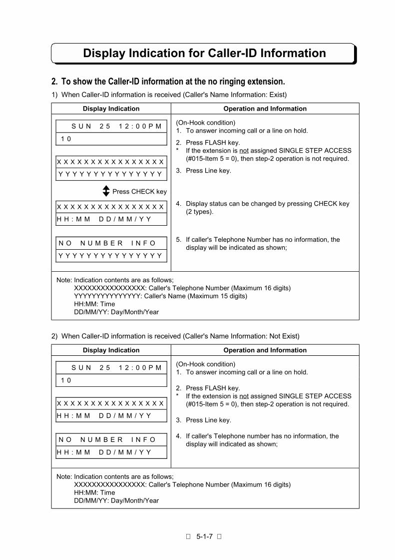
5-1-7
Display Indication for Caller-ID Information
2. To show the Caller-ID information at the no ringing extension.1) When Caller-ID information is received (Caller's Name Information: Exist)
Display Indication Operation and Information
# # S U N # 2 5 # 1 2 : 0 0 P M
1 0 # # # # # # # # # # # # # #
X X X X X X X X X X X X X X X X
Y Y Y Y Y Y Y Y Y Y Y Y Y Y Y
(On-Hook condition)1. To answer incoming call or a line on hold.
2. Press FLASH key.* If the extension is not assigned SINGLE STEP ACCESS
(#015-Item 5 = 0), then step-2 operation is not required.
3. Press Line key.
X X X X X X X X X X X X X X X X
H H : M M # D D / M M / Y Y # #
4. Display status can be changed by pressing CHECK key(2 types).
N O # N U M B E R # I N F O #
Y Y Y Y Y Y Y Y Y Y Y Y Y Y Y
5. If caller's Telephone Number has no information, thedisplay will be indicated as shown;
Note: Indication contents are as follows;XXXXXXXXXXXXXXXX: Caller's Telephone Number (Maximum 16 digits)YYYYYYYYYYYYYYY: Caller's Name (Maximum 15 digits)HH:MM: TimeDD/MM/YY: Day/Month/Year
2) When Caller-ID information is received (Caller's Name Information: Not Exist)
Display Indication Operation and Information
# # S U N # 2 5 # 1 2 : 0 0 P M
1 0 # # # # # # # # # # # # # #
X X X X X X X X X X X X X X X X
H H : M M # D D / M M / Y Y # #
N O # N U M B E R # I N F O #
H H : M M # D D / M M / Y Y # #
(On-Hook condition)1. To answer incoming call or a line on hold.
2. Press FLASH key.* If the extension is not assigned SINGLE STEP ACCESS
(#015-Item 5 = 0), then step-2 operation is not required.
3. Press Line key.
4. If caller's Telephone number has no information, thedisplay will indicated as shown;
Note: Indication contents are as follows;XXXXXXXXXXXXXXXX: Caller's Telephone Number (Maximum 16 digits)HH:MM: TimeDD/MM/YY: Day/Month/Year
Press CHECK key

5-1-8
Display Indication for Caller-ID Information
3) When Caller-ID information is not received
Display Indication Operation and Information
# # S U N # 2 5 # 1 2 : 0 0 P M
1 0 # # # # # # # # # # # # # #
L I N E # X X # # # # # # # # #
N O # C A L L E R # I N F O #
(On-Hook condition)1. To answer incoming call or a line on hold.
2. Press FLASH key.* If the extension is not assigned SINGLE STEP ACCESS
(#015-Item 5 = 0), then step-2 operation is not required.
3. Press Line key.
Note: Indication contents are as follows;XX: Line Number
4) When caller calls from Non Caller-ID Service Area
Display Indication Operation and Information
# # S U N # 2 5 # 1 2 : 0 0 P M
1 0 # # # # # # # # # # # # # #
L I N E # X X # # # # # # # # #
O U T - O F - S T A T E # # # #
o r
L I N E # X X # # # # # # # # #
O U T O F A R E A # #
(On-Hook condition)1. To answer incoming call or a line on hold.
2. Press FLASH key.* If the extension is not assigned SINGLE STEP ACCESS
(#015-Item 5 = 0), then step-2 operation is not required.
3. Press Line key.
Note: Indication contents are as follows;XX: Line Number

5-1-9
Display Indication for Caller-ID Information
5) When caller rejects to display Caller-ID information
Display Indication Operation and Information
# # S U N # 2 5 # 1 2 : 0 0 P M
1 0 # # # # # # # # # # # # # #
L I N E # X X # # # # # # # # #
U N A V A I L A B L E I N F O #
o r
L I N E # X X # # # # # # # # #
P R I V A T E # # # #
(On-Hook condition)1. To answer incoming call or a line on hold.
2. Press FLASH key.* If the extension is not assigned SINGLE STEP ACCESS
(#015-Item 5 = 0), then step-2 operation is not required.
3. Press Line key.
Note: Indication contents are as follows;XX: Line Number
Note 1: Caller-ID feature can be allocated on a line basis (Program #003-Item 5).Note 2: Caller-ID Indication can be assigned on an extension basis (Program #061-Item 2).Note 3: Caller-ID information can be stored to Caller-ID table by assigned KTS (Program #061- Item 3).Note 4: For the Auto Display Indication, the display can show the first incoming call. If the call is
answered or abandoned, the display will show next incoming call.Note 5: The indications “OUT-OF-STATE” and “UNAVAILABLE INFO”, or “OUT OF AREA” and
“PRIVATE” can be selected by Program #018-Item 2.
[ RELATED SYSTEM DATA ]
Program #003-Item 5: CALLER-IDProgram #007: Incoming Trunk Access/AudibleProgram #018-Item 2: Caller-ID Message AssignmentProgram #095-Item 4: Call abandon detection timer
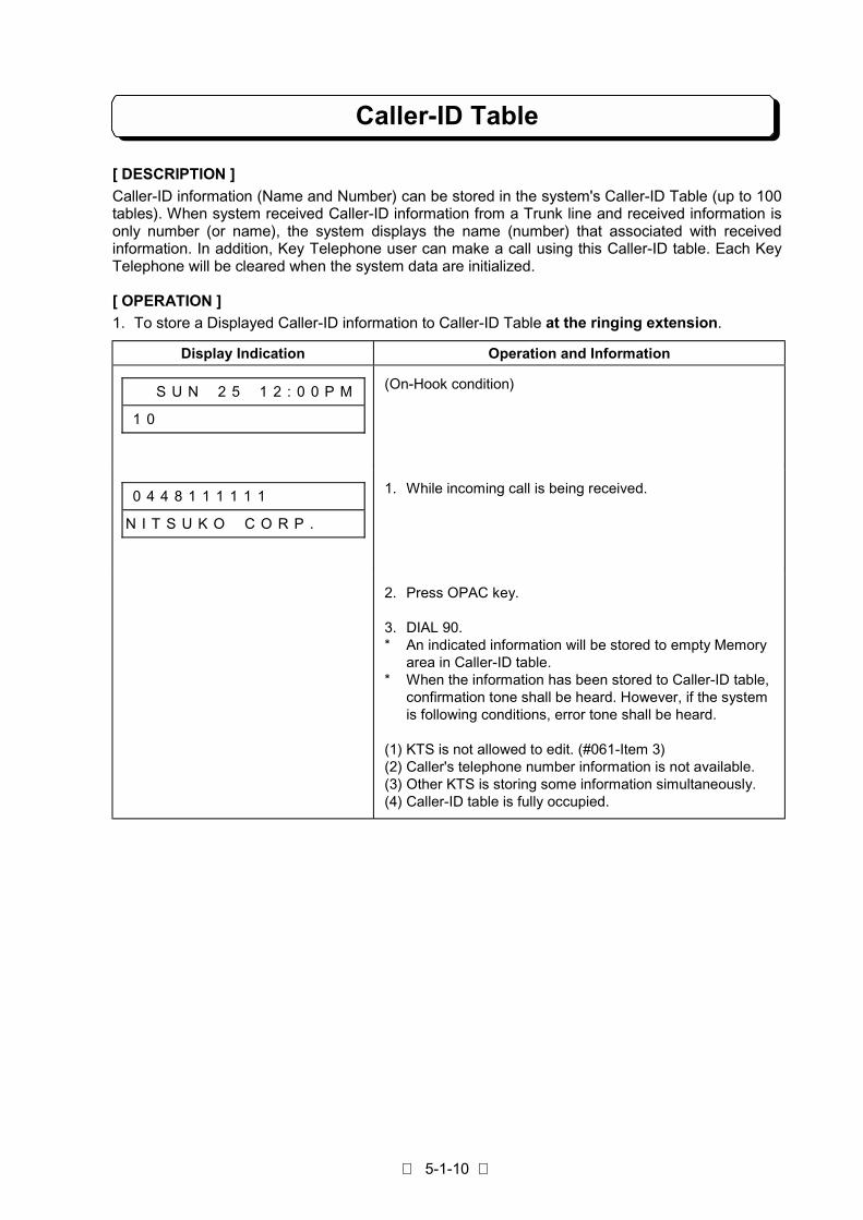
5-1-10
Caller-ID Table
[ DESCRIPTION ]
Caller-ID information (Name and Number) can be stored in the system's Caller-ID Table (up to 100tables). When system received Caller-ID information from a Trunk line and received information isonly number (or name), the system displays the name (number) that associated with receivedinformation. In addition, Key Telephone user can make a call using this Caller-ID table. Each KeyTelephone will be cleared when the system data are initialized.
[ OPERATION ]
1. To store a Displayed Caller-ID information to Caller-ID Table at the ringing extension.
Display Indication Operation and Information
# # S U N # 2 5 # 1 2 : 0 0 P M
1 0 # # # # # # # # # # # # # #
(On-Hook condition)
0 4 4 8 1 1 1 1 1 1 # # # # # #
N I T S U K O # C O R P . # # #
1. While incoming call is being received.
2. Press OPAC key.
3. DIAL 90.* An indicated information will be stored to empty Memory
area in Caller-ID table.* When the information has been stored to Caller-ID table,
confirmation tone shall be heard. However, if the systemis following conditions, error tone shall be heard.
(1) KTS is not allowed to edit. (#061-Item 3)(2) Caller's telephone number information is not available.(3) Other KTS is storing some information simultaneously.(4) Caller-ID table is fully occupied.

5-1-11
Caller-ID Table
2. To store a Displayed Caller-ID information to Caller-ID Table at the no ringing extension.
Display Indication Operation and Information
# # S U N # 2 5 # 1 2 : 0 0 P M
1 0 # # # # # # # # # # # # # #
(On-Hook condition)1. To answer incoming call or line on hold.
0 4 4 8 1 1 1 1 1 1 # # # # # #
N I T S U K O # C O R P . # # #
2. Press FLASH key.3. Press Line key.* If a caller's number information is not available, the
message (NO NUMBER INFO) will be shown at uppercolumn of Display.
* The information is recommended to be entered in thecombination of Number and Name.
4. Press OPAC key.
5. Dial 90.* An indicated information will be stored to empty Memory
area in Caller-ID table.* When the information has been stored to Caller-ID table,
confirmation tone shall be heard. However, if the systemis following conditions, error tone shall be heard.
(1) KTS is not allowed to edit. (#061-Item 3)(2) Caller's telephone number information is not available.(3) Other KTS is storing some information simultaneously.(4) Caller-ID table is fully occupied.
Note: If you assigned to DISABLE (at #015-Item 5), the above operation No. 2 is not required.

5-1-12
Caller-ID Table
3. To use Bin Number(1) To store the new information/To change the current information
Display Indication Operation and Information
# # S U N # 2 5 # 1 2 : 0 0 P M
1 0 # # # # # # # # # # # # # #
(On-Hook condition)
B I N # N O . # # # # # # # # # 1. Press OPAC key.2. Dial 91.
B I N # N O . 0 0 1 # # # # # # 3. Dial 001. (up to 100)
B I N # N O . 0 0 1 # # # # # # 4. Press ∗ key.* If wrong Bin number is entered, the display shall return to
input mode for Bin number.* If a Telephone Number is stored in Table, it shall be
displayed in lower column.* If a Telephone Number is not stored in Table, the lower
column shall be displayed as "INPUT TEL NO.".
# # S U N # 2 5 # 1 2 : 0 0 P M * If KTS is not allowed to edit (#061-Item 3) or other KTS isstoring information in same time, Error Tone shall beheard and return to the idle condition.
B I N # N O . 0 0 1 # # # # # #
# # # # # # 0 4 4 8 1 1 1 1 1 1
5. Dial Telephone Number.(for example: 044-811-1111)
* If the dial input has error, OPAC key is to clear the lowercolumn. Then input assign.
* If the telephone number is not necessary to change, thisoperation shall be skipped.
B I N # N O . 0 0 1 # # # # # # 6. Press ∗ key.* If a caller's name is stored in Table, it shall be displayed
in lower column.* If a caller's name is not stored in tale, the lower column
shall be blanked.

5-1-13
Caller-ID Table
(1) To store the new information/To change the current information (Cont'd)
Display Indication Operation and Information
B I N # N O . 0 0 1 # # # # # #
N I T S U K O # C O R P . # # #
7. Input Caller's Name.(Example: NITSUKO CORP.)
* Dial key (0 - 9): Numbers∗ : Left shift for cursor#: Right shift for cursor
One touch key (1-3) with dial (0-9): letter and symbolsOne touch key 4: SpaceOne touch key 5: Delete a characterOne touch key 6: delete all character
* It can input maximum 15 characters.* If the telephone number is not necessary to change, this
operation shall be skipped.
B I N # N O . 0 0 1 # # # # # #
# # S U N # 2 5 # 1 2 : 0 0 P M
1 0 # # # # # # # # # # # # # #
8. Press HOLD key. (entry finished)* This is as same condition as at step 2.
Next information can be entered, if necessary.
9. Press CLEAR Key. (operation finished)
(2) To delete the current information
Display Indication Operation and Information
# # S U N # 2 5 # 1 2 : 0 0 P M
1 0 # # # # # # # # # # # # # #
(Caller-ID information has already stored to the table.)
B I N # N O . # # # # # # # # # 1. Press OPAC key. (On-Hook condition)2. Dial 91.
B I N # N O . 0 0 1 # # # # # # 3. Dial 001. (up to 100)
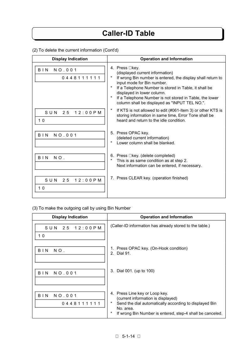
5-1-14
Caller-ID Table
(2) To delete the current information (Cont'd)
Display Indication Operation and Information
B I N # N O . 0 0 1 # # # # # #
# # # # # # 0 4 4 8 1 1 1 1 1 1
4. Press ∗ key.(displayed current information)
* If wrong Bin number is entered, the display shall return toinput mode for Bin number.
* If a Telephone Number is stored in Table, it shall bedisplayed in lower column.
* If a Telephone Number is not stored in Table, the lowercolumn shall be displayed as "INPUT TEL NO.".
# # S U N # 2 5 # 1 2 : 0 0 P M
1 0 # # # # # # # # # # # # # #
* If KTS is not allowed to edit (#061-Item 3) or other KTS isstoring information in same time, Error Tone shall beheard and return to the idle condition.
B I N # N O . 0 0 1 # # # # # # 5. Press OPAC key.(deleted current information)
* Lower column shall be blanked.
B I N # N O . # # # # # # # # # 6. Press ∗ key. (delete completed)* This is as same condition as at step 2.
Next information can be entered, if necessary.
# # S U N # 2 5 # 1 2 : 0 0 P M
1 0 # # # # # # # # # # # # # #
7. Press CLEAR key. (operation finished)
(3) To make the outgoing call by using Bin Number
Display Indication Operation and Information
# # S U N # 2 5 # 1 2 : 0 0 P M
1 0 # # # # # # # # # # # # # #
(Caller-ID information has already stored to the table.)
B I N # N O . # # # # # # # # # 1. Press OPAC key. (On-Hook condition)2. Dial 91.
B I N # N O . 0 0 1 # # # # # # 3. Dial 001. (up to 100)
B I N # N O . 0 0 1 # # # # # #
# # # # # # 0 4 4 8 1 1 1 1 1 1
4. Press Line key or Loop key.(current information is displayed)
* Send the dial automatically according to displayed BinNo. area.
* If wrong Bin Number is entered, step-4 shall be canceled.

5-1-15
Caller-ID Table
(4) To store the new information to idle Bin Number
Display Indication Operation Information
# # S U N # 2 5 # 1 2 : 0 0 P M
1 0 # # # # # # # # # # # # # #
(Caller-ID information has already stored to the table.)
B I N # N O . 0 0 2 # # # # # #
I N P U T # T E L # N O . # # #
1. Press OPAC key. (On-Hook condition)2. Dial 92.* Idle Bin Number shall be displayed automatically.
# # S U N # 2 5 # 1 2 : 0 0 P M
T A B L E # I S # F U L L # # #
* If Caller-ID table is fully occupied, error tone shall beheard and the indication shall be as shown;
# # S U N # 2 5 # 1 2 : 0 0 P M
1 0 # # # # # # # # # # # # # #
* If KTS is not allowed to edit (#061-Item 3) or other KTS isstoring some information, error tone shall be heard andreturn to idle condition.
B I N # N O . 0 0 2 # # # # # #
# # # # # # 0 4 4 8 1 3 7 1 0 1
3. Dial telephone number.(for example: 044-813-7101)
B I N # N O . 0 0 2 # # # # # # 4. Press ∗ key.
B I N # N O . 0 0 2 # # # # # #
N I T S U K O # O V E R S E A
5. Input the Name.(for example: NITSUKO OVERSEA)
B I N # N O . 0 1 0 # # # # # #
I N P U T # T E L # N O . # # #
6. Press HOLD key. (entry completed)* This is as same condition as at step 2.
Next information can be entered, if necessary.(Search the idle Bin No. automatically)
# # S U N # 2 5 # 1 2 : 0 0 P M
T A B L E # I S # F U L L # # #
* If Caller-ID table is fully occupied, error tone shall beheard and the indication shall be as shown;
# # S U N # 2 5 # 1 2 : 0 0 P M
1 0 # # # # # # # # # # # # # #
7. Press CLEAR key. (operation finished)

5-1-16
Caller-ID Table
4. To search the Caller's Telephone Number(1) To make the outgoing call by using the searched Telephone Number
Display Indication Operation and Information
# # S U N # 2 5 # 1 2 : 0 0 P M
1 0 # # # # # # # # # # # # # #
(Caller-ID information has already stored to the table.)
S E A R C H # N U M B E R # # 1. Press OPAC key. (On-Hook condition)2. Dial 93.
S E A R C H # N U M B E R # #
# # # # # # # # # # # # # # 0 4
3. Press Caller's Telephone Number (one digit to 16 digitsfrom ahead) for search.
* If the dial input has error, OPAC key is to clear the lowercolumn. Then input again.
0 4 4 8 1 1 1 1 1 1 # # # # # #
N I T S U K O # C O R P . # # #
4. Press ∗ key.* The corresponding data shall be displayed.
0 4 4 8 1 3 7 1 0 1 # # # # # #
N I T S U K O # O V E R S E A
5. Press # key (search the forward information) or ∗ key(search the backward information).
S E A R C H # N U M B E R # #
L I S T # E N D # # # # # # # #
* If the information is not in table, the indication shall be asshown;
L I N E # 0 1 # # # # # # # # #
# # # # # # 0 4 4 8 1 1 1 1 1 1
6. Press Line key or Loop key.
* Send the dial automatically according to the displayed BinNo. area.
(2) To change the current information by searching the Telephone Number
Display Indication Operation and Information
# # S U N # 2 5 # 1 2 : 0 0 P M
1 0 # # # # # # # # # # # # # #
(Caller-ID information has already stored to the table.)
S E A R C H # N U M B E R # # 1. Press OPAC key. (On-Hook condition)2. Dial 93.

5-1-17
Caller-ID Table
(2) To change the current information by searching the Telephone Number (Cont'd)
Display Indication Operation and Information
S E A R C H # N U M B E R # #
# # # # # # # # # # # # # # 0 4
3. Press Caller's Telephone Number (one digit to 16 digitsfrom ahead) for Search.
* If the dial input has error, OPAC key is to clear the lowercolumn. Then input again.
0 4 4 8 1 1 1 1 1 1 # # # # # #
N I T S U K O # C O R P . # # #
4. Press ∗ key.* The corresponding data shall be displayed.
0 4 4 8 1 3 7 1 0 1 # # # # # #
N I T S U K O # O V E R S E A
5. Press # key (search the forward information) or ∗ key(search the Backward information).
S E A R C H # N U M B E R # #
L I S T # E N D # # # # # # # #
* If information is not in table, the indication shall be asshown;
B I N # N O . 0 1 2 # # # # # #
# # # # # # 0 4 4 8 1 1 1 1 1 1
6. Press HOLD key.* Corresponding Bin No. shall be displayed according to
the stored Telephone Number.
# # S U N # 2 5 # 1 2 : 0 0 P M
1 0 # # # # # # # # # # # # # #
* If KTS is not allowed to edit (#061-Item 3) or other KTS isstoring some information, error tone shall be heard andreturn to idle condition.
B I N # N O . 0 1 2 # # # # # #
# # # # # # 0 1 2 3 4 5 6 7 8 9
7. Dial new Telephone Number.(for example: 0123456789)
* If the Telephone Number is not necessary to change, thisoperation shall be skipped.
B I N # N O . 0 1 2 # # # # # #
N I T S U K O # C O R P . # # #
8. Press ∗ key.* Stored Name shall be displayed.
B I N # N O . 0 1 2 # # # # # #
B C D # L I M I T E D # # # # #
9. Input new Name. (for example: BCD LIMITED)* If the Caller's Name is not necessary to change, this
operation shall be skipped.
# # S U N # 2 5 # 1 2 : 0 0 P M
1 0 # # # # # # # # # # # # # #
10.Press HOLD key. (entry completed)* Return to the idle condition.

5-1-18
Caller-ID Table
(3) To delete the current information by Searching the Telephone Number
Display Indication Operation and Information
# # S U N # 2 5 # 1 2 : 0 0 P M
1 0 # # # # # # # # # # # # # #
(Caller-ID information has already stored to the table.)
S E A R C H # N U M B E R # # 1. Press OPAC key. (On-Hook condition)2. Dial 93.
S E A R C H # N U M B E R # #
# # # # # # # # # # # # # # 0 4
3. Press Caller's Telephone Number (one digit to 16 digitsfrom ahead) for search.
* If the dial input has error, OPAC key is to clear the lowercolumn. Then input again.
0 4 4 8 1 1 1 1 1 1 # #
N I T S U K O C O R P .
4. Press ∗ key.* The corresponding data shall be displayed.
0 4 4 8 1 3 7 1 0 1 # #
N I T S U K O O V E R S E A
5. Press # key (search the forward information) or ∗ key(search the Backward information).
S E A R C H # N U M B E R # #
L I S T # E N D # # # # # # # #
* If information is not in table, the indication shall be asshown;
B I N # N O . 0 1 2 # # # # # #
# # # # # # 0 4 4 8 1 1 1 1 1 1
6. Press HOLD key.* Corresponding Bin No. shall be displayed according to
the stored Telephone Number.
# # S U N # 2 5 # 1 2 : 0 0 P M
1 0 # # # # # # # # # # # # # #
* If KTS is not allowed to edit (#061-Item 3) or other KTS isstoring some information, error tone shall be heard andreturn to idle condition.
B I N # N O . 0 1 2 # # # # # # 7. Press OPAC key.(delete Current information)
* Lower column shall be blanked.
# # S U N # 2 5 # 1 2 : 0 0 P M
1 0 # # # # # # # # # # # # # #
8. Press ∗ key. (delete completed)* Return to the idle condition.

5-1-19
Caller-ID Table
5. To search the Caller's Name(1) To make the outgoing call by using the searched caller's Name
Display Indication Operation and Information
# # S U N # 2 5 # 1 2 : 0 0 P M
1 0 # # # # # # # # # # # # # #
(Caller-ID information has already stored to the table.)
S E A R C H # N A M E # # # # 1. Press OPAC key. (On Hook condition)2. Dial 94. (search the name)
S E A R C H # N A M E # # # #
N I T S U K O # # # # # # # # #
3. Press Caller's Name (one digit to 15 digits from ahead)for search.
* If the Name input has error, One-Touch key 4 (Space),One Touch key 5 (Delete a character) and One Touchkey 6 (delete all characters) shall be used for change thename.
0 4 4 8 1 1 1 1 1 1 # # # # # #
N I T S U K O # C O R P . # # #
4. Press HOLD key.* The corresponding data shall be displayed.
0 4 4 8 1 3 7 1 0 1 # # # # # #
N I T S U K O # O V E R S E A
5. Press # key (search the forward information) or ∗ key(search the Backward information).
S E A R C H # N A M E # # # #
L I S T # E N D # # # # # # # #
* If the information is not in table, the indication shall be asshown;
L I N E # 0 1 # # # # # # # # #
# # # # # # 0 4 4 8 1 1 1 1 1 1
6. Press Line key or Loop key.
* Send the dial automatically according to the displayed BinNo. area.

5-1-20
Caller-ID Table
(2) To change the current information by searching the caller's Name
Display Indication Operation and Information
# # S U N # 2 5 # 1 2 : 0 0 P M
1 0 # # # # # # # # # # # # # #
(Caller-ID information has already stored to the table.)
S E A R C H # N A M E # # # # 1. Press OPAC key. (On Hook condition)2. Dial 94. (search the name)
S E A R C H # N A M E # # # #
N I T S U K O
3. Press Caller's Name (one digit to 15 digits from ahead)for search.
* If the Name input has error, One-Touch key 4 (Space),One Touch key 5 (Delete a character) and One Touchkey 6 (delete all characters) shall be used for change thename.
0 4 4 8 1 1 1 1 1 1 # # # # # #
N I T S U K O # C O R P . # # #
4. Press HOLD key.* The corresponding data shall be displayed.
0 4 4 8 1 3 7 1 0 1 # # # # # #
N I T S U K O # O V E R S E A
5. Press # key (search the forward information) or ∗ key(search the Backward information).
S E A R C H # N A M E # # # #
L I S T # E N D # # # # # # # #
* If the information is not in table, the indication is asshown;
B I N # N O . 0 1 2 # # # # # #
# # # # # # 0 4 4 8 1 1 1 1 1 1
6. Press HOLD key.* Corresponding Bin No. shall be displayed according to
the stored Telephone Number.
# # S U N # 2 5 # 1 2 : 0 0 P M
1 0 # # # # # # # # # # # # # #
* If KTS is not allowed to edit (#061-Item 3) or other KTS isstoring some information, error tone shall be heard andreturn to idle condition.
B I N # N O . 0 1 2 # # # # # #
# # # # # # 0 1 2 3 4 5 6 7 8 9
7. Dial new Telephone Number.(for example: 0123456789)
* If the Telephone Number is not necessary to change, thisoperation shall be skipped.
B I N # N O . 0 1 2 # # # # # #
N I T S U K O # C O R P . # # #
8. Press ∗ .* The stored Name shall be displayed
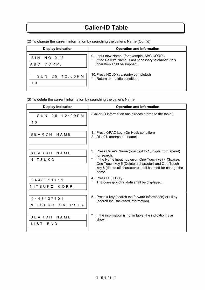
5-1-21
Caller-ID Table
(2) To change the current information by searching the caller's Name (Cont'd)
Display Indication Operation and Information
B I N # N O . 0 1 2 # # # # # #
A B C # C O R P . # # # # # # #
9. Input new Name. (for example: ABC CORP.)* If the Caller's Name is not necessary to change, this
operation shall be skipped.
# # S U N # 2 5 # 1 2 : 0 0 P M
1 0 # # # # # # # # # # # # # #
10.Press HOLD key. (entry completed)* Return to the idle condition.
(3) To delete the current information by searching the caller's Name
Display Indication Operation and Information
# # S U N # 2 5 # 1 2 : 0 0 P M
1 0 # # # # # # # # # # # # # #
(Caller-ID information has already stored to the table.)
S E A R C H # N A M E # # # # 1. Press OPAC key. (On Hook condition)2. Dial 94. (search the name)
S E A R C H # N A M E # # # #
N I T S U K O # # # # # # # # #
3. Press Caller's Name (one digit to 15 digits from ahead)for search.
* If the Name input has error, One-Touch key 4 (Space),One Touch key 5 (Delete a character) and One Touchkey 6 (delete all characters) shall be used for change thename.
0 4 4 8 1 1 1 1 1 1 # # # # # #
N I T S U K O # C O R P . # # #
4. Press HOLD key.* The corresponding data shall be displayed.
0 4 4 8 1 3 7 1 0 1 # # # # # #
N I T S U K O # O V E R S E A
5. Press # key (search the forward information) or ∗ key(search the Backward information).
S E A R C H # N A M E # # # #
L I S T # E N D # # # # # # # #
* If the information is not in table, the indication is asshown;
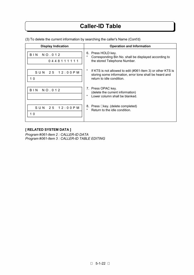
5-1-22
Caller-ID Table
(3) To delete the current information by searching the caller's Name (Cont'd)
Display Indication Operation and Information
B I N # N O . 0 1 2 # # # # # #
# # # # # # 0 4 4 8 1 1 1 1 1 1
6. Press HOLD key.* Corresponding Bin No. shall be displayed according to
the stored Telephone Number.
# # S U N # 2 5 # 1 2 : 0 0 P M
1 0 # # # # # # # # # # # # # #
* If KTS is not allowed to edit (#061-Item 3) or other KTS isstoring some information, error tone shall be heard andreturn to idle condition.
B I N # N O . 0 1 2 # # # # # # 7. Press OPAC key.(delete the current information)
* Lower column shall be blanked.
# # S U N # 2 5 # 1 2 : 0 0 P M
1 0 # # # # # # # # # # # # # #
8. Press ∗ key. (delete completed)* Return to the idle condition.
[ RELATED SYSTEM DATA ]
Program #061-Item 2 : CALLER-ID DATAProgram #061-Item 3 : CALLER-ID TABLE EDITING
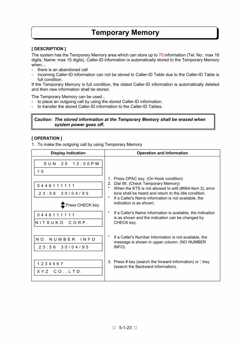
5-1-23
Temporary Memory
[ DESCRIPTION ]
The system has the Temporary Memory area which can store up to 70 information (Tel. No.: max 16digits, Name: max 15 digits). Caller-ID information is automatically stored to the Temporary Memorywhen...- there is an abandoned call- incoming Caller-ID information can not be stored to Caller-ID Table due to the Caller-ID Table is
full condition.If the Temporary Memory is full condition, the oldest Caller-ID information is automatically deletedand then new information shall be stored.
The Temporary Memory can be used...- to place an outgoing call by using the stored Caller-ID information.- to transfer the stored Caller-ID information to the Caller-ID Tables.
[ OPERATION ]
1. To make the outgoing call by using Temporary Memory
Display Indication Operation and Information
# # S U N # 2 5 # 1 2 : 0 0 P M
1 0 # # # # # # # # # # # # # #
0 4 4 8 1 1 1 1 1 1 # # # # # #
2 3 : 5 6 # 3 0 / 0 4 / 9 5 # #
1. Press OPAC key. (On Hook condition)2. Dial 95. (Check Temporary Memory)* When the KTS is not allowed to edit (#064-Item 2), error
tone shall be heard and return to the idle condition.* If a Caller's Name information is not available, the
indication is as shown;
0 4 4 8 1 1 1 1 1 1 # # # # # #
N I T S U K O # C O R P . # # #
* If a Caller's Name information is available, the indicationis as shown and the indication can be changed byCHECK key.
N O # N U M B E R # I N F O #
2 3 : 5 6 # 3 0 / 0 4 / 9 5 # #
* If a Caller's Number Information is not available, themessage is shown in upper column. (NO NUMBERINFO)
1 2 3 4 5 6 7 # # # # # # # # #
X Y Z # C O . , L T D . # # # #
3. Press # key (search the forward information) or ∗ key(search the Backward information).
Caution: The stored information at the Temporary Memory shall be erased whensystem power goes off.
Press CHECK key

5-1-24
Temporary Memory
1. To make the outgoing call by using Temporary Memory (Cont'd)
Display Indication Operation and Information
T E M P O R A R Y # M E M O R Y
L I S T # E N D # # # # # # # #
* If the information is not in memory, the indication is asshown;
L I N E # 0 1 # # # # # # # # #
# # # # # # 0 4 4 8 1 1 1 1 1 1
4. Press Line key or Loop key.
* Send the dial automatically according to the indicatedNumber on the display.
2. To clear the stored information at Temporary Memory
Display Indication Operation and Information
# # S U N # 2 5 # 1 2 : 0 0 P M
1 0 # # # # # # # # # # # # # #
1. Press OPAC key. (On Hook condition)2. Dial 96. (clear Temporary Memory)* All data shall be erased in the memories and return to the
idle condition.* Confirmation tone shall be heard.
3. To entry the stored information at Temporary Memory to Caller-ID Table
Display Indication Operation and Information
# # S U N # 2 5 # 1 2 : 0 0 P M
1 0 # # # # # # # # # # # # # #
0 4 4 8 1 1 1 1 1 1 # # # # # #
2 3 : 5 6 # 3 0 / 0 4 / 9 5 # #
1. Press OPAC key. (On Hook condition)2. Dial 95. (check Temporary Memory)* If a Caller's Name information is not available, the
indication is as shown;
0 4 4 8 1 1 1 1 1 1 # # # # # #
N I T S U K O # C O R P . # # #
* If a Caller's Name information is available, the indicationis as shown and the indication can be changed byCHECK key.
1 2 3 4 5 6 7 # # # # # # # # #
X Y Z # C O . , L T D . # # # #
3. Press # key (search the forward information) or ∗ key(search the Backward information).
T E M P O R A R Y # M E M O R Y
L I S T # E N D # # # # # # # #
* If the information is not in memory, the indication is asshown;

5-1-25
Temporary Memory
3. To entry the stored information at Temporary Memory to Caller-ID Table (Cont'd)
Display Indication Operation and Information
1 2 3 4 5 6 7 # # # # # # # # #
X Y Z # C O . , L T D . # # # #
# # S U N # 2 5 # 1 2 : 0 0 P M
1 0 # # # # # # # # # # # # # #
4. Press HOLD Key. (store to Caller-ID table)* Indicated information shall be stored to Caller-ID Table.* Confirmation tone shall be heard.
* When the other Key Telephones are operating to store ortelephone number information is not available ontemporary memory tables, error tone shall be heard andreturn to the idle condition.
# # S U N # 2 5 # 1 2 : 0 0 P M
T A B L E # I S # F U L L # # #
* If Caller-ID table is fully occupied, error tone shall beheard and the indication is as shown;
# # S U N # 2 5 # 1 2 : 0 0 P M
1 0 # # # # # # # # # # # # # #
5. Press CLEAR key. (operation finished)
Note: When Caller-ID information is stored in the Temporary memory, (when there is anabandoned call) "EXISTING I.D." indication shall automatically be appeared on lowercolumn of Key Telephone display. Existence of the stored information(s) at the TemporaryMemory can be recognized only by showing the display. This function is available forassigned extension user(s) in Program #064-Item 2.
[ RELATED SYSTEM DATA ]
Program #064-Item 2: TEMPORARY MEMORY STATUS
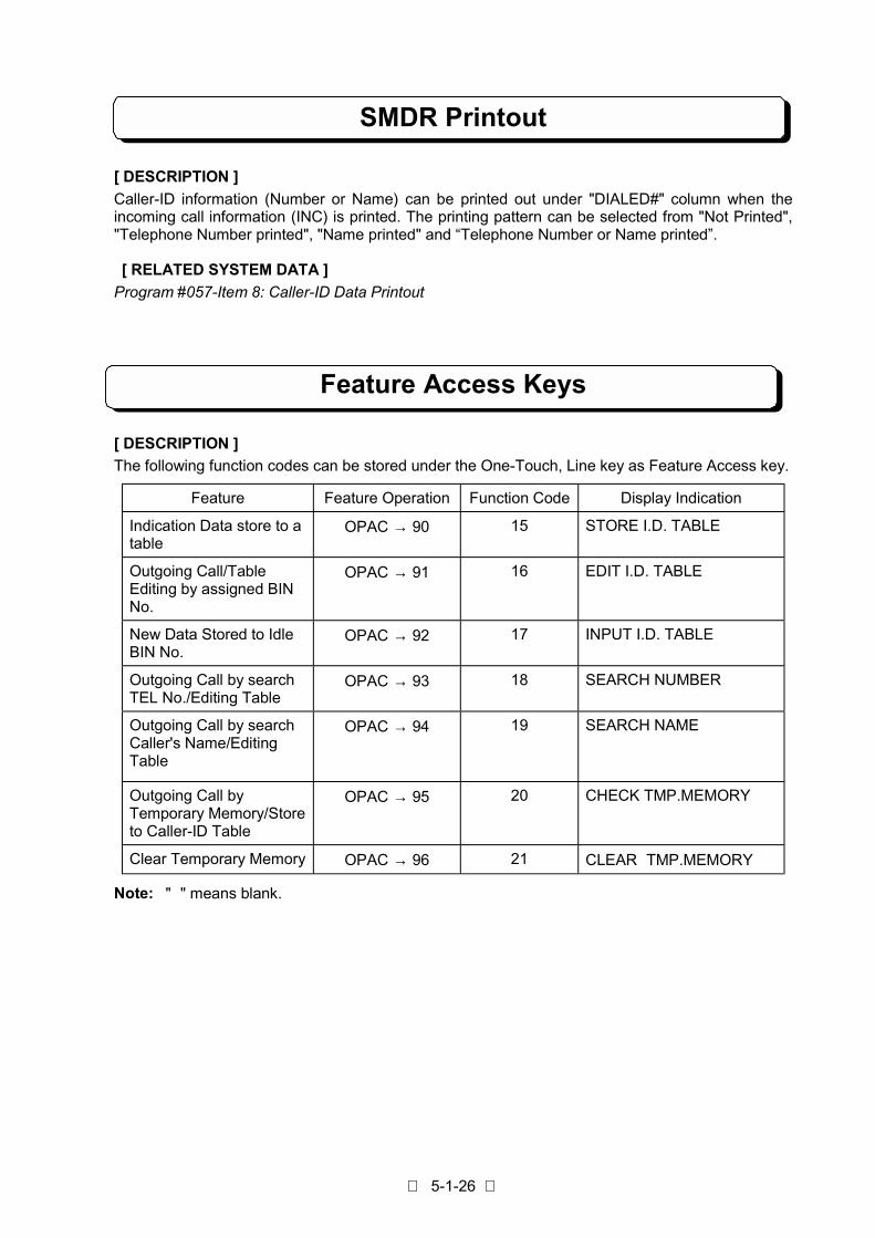
5-1-26
SMDR Printout
[ DESCRIPTION ]
Caller-ID information (Number or Name) can be printed out under "DIALED#" column when theincoming call information (INC) is printed. The printing pattern can be selected from "Not Printed","Telephone Number printed", "Name printed" and “Telephone Number or Name printed”.
[ RELATED SYSTEM DATA ]
Program #057-Item 8: Caller-ID Data Printout
Feature Access Keys
[ DESCRIPTION ]
The following function codes can be stored under the One-Touch, Line key as Feature Access key.
Feature Feature Operation Function Code Display Indication
Indication Data store to atable
OPAC → 90 15 STORE I.D. TABLE
Outgoing Call/TableEditing by assigned BINNo.
OPAC → 91 16 EDIT I.D. TABLE
New Data Stored to IdleBIN No.
OPAC → 92 17 INPUT I.D. TABLE
Outgoing Call by searchTEL No./Editing Table
OPAC → 93 18 SEARCH NUMBER
Outgoing Call by searchCaller's Name/EditingTable
OPAC → 94 19 SEARCH NAME
Outgoing Call byTemporary Memory/Storeto Caller-ID Table
OPAC → 95 20 CHECK TMP.MEMORY
Clear Temporary Memory OPAC → 96 21 CLEAR TMP.MEMORY
Note: " " means blank.

5-1-27
Feature Access Keys
[ OPERATION ]
The operations of store/cancel/confirm are as follows;
1. To store:(1) Lift handset or press SPK key.(2) Press ICM key. (See Note)(3) Press OPAC Key.(4) Dial 4.(5) Press one of Line or F1 - F10 keys.(6) Dial desired Function Code (15 - 21).(7) Dial ∗ .(8) Hang up or press SPK key.
2. To cancel:(1) Lift handset or press SPK key.(2) Press ICM key. (See Note)(3) Press OPAC Key.(4) Dial 4.(5) Press one of Line or F1 - F10 keys.(6) Dial 0, 0.(7) Dial ∗ .(8) Hang up or press SPK key.
3. To confirm:(1) On-Hook condition.(2) Press CHECK Key.(3) Press one of Line or F1 - F10 Keys. (The indication shall be shown.)(4) Press CLEAR key. (return to the idle condition)
Note: If Program #075-Item 4 = 0 (No tone), skip Step 2.

5-1-28
List of Display Information
No. Contents Display Indication Note
1 Caller-ID Information
* When Caller-IDinformation isreceived.
X X X X X X X X X X X X X X X X
Y Y Y Y Y Y Y Y Y Y Y Y Y Y Y
X: Caller's telephone Number(Maximum 16 digits)
Y: Caller's Name(Maximum 15 digits).
2 Caller-ID dataInformation
* If a Caller-IDinformation has nocaller's name.
X X X X X X X X X X X X X X X X
H H : M M # D D / M M / Y Y # #
X: Caller's telephone NumberHH:MM: TimeDD/MM/YY: Date/Month/Year
3 Caller-ID Information
* When Caller-IDinformation is notreceived.
L I N E # X X # # # # # # # # #
N O # C A L L E R # I N F O # #
XX: Line Number
L I N E # X X # # # # # # # # #
O U T - O F - S T A T E # # # #
4 Caller-ID Information
* If Caller calls fromnon Caller-IDservice area.
L I N E # X X # # # # # # # # #
O U T O F A R E A # # #
XX: Line Number
L I N E # X X # # # # # # # # #
U N A V A I L A B L E I N F O #
5 Caller-ID Information
* If the callerrejects to displayCaller-IDinformation
L I N E # X X # # # # # # # # #
P R I V A T E #
XX: Line Number
6 Caller-ID Information
* If the Caller-IDinformation has noNumber.
N O # N U M B E R # I N F O #
H H : M M # D D / M M / Y Y # #
HH:MM: TimeDD/MM/YY: Date/Month/Year
7 Caller-ID TableInformation
* Bin No. for Caller -ID Table.
B I N # N O . # # # # # # # # #
8 Caller-ID TableInformation
* Bin No. for Caller-IDTable.
B I N # N O . X X X # # # # # #XXX: Bin Number
(001 to 100)

5-1-29
List of Display Information
No. Contents Display Indication Note
9 Caller-ID TableInformation
* Bin No. Informationin the Table.
B I N # N O . X X X # # # # # #
Y Y Y Y Y Y Y Y Y Y Y Y Y Y Y Y
XXX: Bin NumberY: Telephone Number
10 Caller-ID TableInformation
* Bin No. Informationin the Table.
B I N # N O . X X X # # # # # #
Y Y Y Y Y Y Y Y Y Y Y Y Y Y Y
XXX: Bin NumberY: Name
11 Caller-ID TableInformation
* Input mode forTelephone Number.
B I N # N O . X X X # # # # # #
I N P U T # T E L # N O . # # #
XXX: Bin Number
12 Caller-ID TableInformation
* When the Caller-IDTable is fullyoccupied.
# # S U N # 2 5 # 1 2 : 0 0 P M
T A B L E # I S # F U L L # # #
13 Caller-ID TableInformation
* Search TelephoneNumber mode.
S E A R C H # N U M B E R # #
14 Caller-ID TableInformation S E A R C H # N U M B E R # #
# # # # # # # # # # # # # X X X
XXX: Telephone Number fromahead.(Maximum 16 digits)
15 Caller-ID TableInformation
* When theinformation isfinished in theTable.
S E A R C H # N U M B E R # #
L I S T E N D # # # # # # # #
16 Caller-ID TableInformation
* Search Namemode.
S E A R C H # N A M E # # # #
17 Caller-ID TableInformation S E A R C H # N A M E # # # #
# # # # # # # # # # X X X X X X
XXXXXX: A Name from ahead.(Maximum 15 digits)

5-1-30
List of Display Information
No. Contents Display Indication Note
18 Caller-ID TableInformation
* When theinformation isfinished in table.
S E A R C H # N A M E # # # #
L I S T # E N D # # # # # # # #
19 Temporary MemoryInformation
* When theinformation isfinished in Memory.
T E M P O R A R Y # M E M O R Y
L I S T # E N D # # # # # # # #
20 Display information foroutgoing call. L I N E # X X # # # # # # # # #
Y Y Y Y Y Y Y Y Y Y Y Y Y Y Y Y
XX: Line Number
Y : Telephone Number
21 Temporary MemoryInformation
* When theinformation ismemorized.
# # S U N # 2 5 # 1 2 : 0 0 P M
E X I S T I N G # I . D . # # #
To confirm one TouchFeature Access key. # # S U N # 2 5 # 1 2 : 0 0 P M
S T O R E # I . D . # T A B L E
# # S U N # 2 5 # 1 2 : 0 0 P M
# E D I T # I . D . # T A B L E
# # S U N # 2 5 # 1 2 : 0 0 P M
I N P U T # I . D . # T A B L E
# # S U N # 2 5 # 1 2 : 0 0 P M
# # # S E A R C H # N U M B E R
22
# # S U N # 2 5 # 1 2 : 0 0 P M
# # # # # S E A R C H # N A M E

5-1-31
List of Display Information
No. Contents Display Indication Note
To confirm one TouchFeature Access key.
(Cont’d)
# # S U N # 2 5 # 1 2 : 0 0 P M
C H E C K # T M P . M E M O R Y
22
# # S U N # 2 5 # 1 2 : 0 0 P M
C L E A R # T M P . M E M O R Y
PART 5-2
Voice Announce Unit

Table of Contents
General ・・・・・・・・・・・・・・・・・・・・・・・・・・・・・・・・・・・・・・・・・・・・・・・・・・・・・・・・・・・・・・・・・・・・・・・・・・・・・・ 5-2-1
Required Item ・・・・・・・・・・・・・・・・・・・・・・・・・・・・・・・・・・・・・・・・・・・・・・・・・・・・・・・・・・・・・・・・・・・・・・・・ 5-2-1
Installation of VAU-M1 Unit ・・・・・・・・・・・・・・・・・・・・・・・・・・・・・・・・・・・・・・・・・・・・・・・・・・・・・・・・・・・ 5-2-2
FAX Connection・・・・・・・・・・・・・・・・・・・・・・・・・・・・・・・・・・・・・・・・・・・・・・・・・・・・・・・・・・・・・・・・・・・・・・ 5-2-3
Preparation for Attendant Message ・・・・・・・・・・・・・・・・・・・・・・・・・・・・・・・・・・・・・・・・・・・・・・・・・・・ 5-2-4
Basic Programming・・・・・・・・・・・・・・・・・・・・・・・・・・・・・・・・・・・・・・・・・・・・・・・・・・・・・・・・・・・・・・・・・・・ 5-2-7
Important Notice・・・・・・・・・・・・・・・・・・・・・・・・・・・・・・・・・・・・・・・・・・・・・・・・・・・・・・・・・・・・・・・・・・・・・・ 5-2-7
VAU Operation Flowchart・・・・・・・・・・・・・・・・・・・・・・・・・・・・・・・・・・・・・・・・・・・・・・・・・・・・・・・・・・・・・ 5-2-8

5-2-1
General
Required Items
Voice Announce Unit (NX8E-VAU-M1) can be installed to the TX-Z2 system.
Voice announce automatically answers the system’s incoming calls and plays a pre-recorded message.It helps outside callers to reach the FAX Machine, desired extension or Hunt group speedy without amistake. It can answer up to Two Incoming calls simultaneously.
The VAU allows you to record Four Outgoing Messages(1-4) for Automated Attendant which are pre-selected out of eight types of message. The total recording time for all Message is 60 seconds (15sec./Message). Since all of these messages are recorded by the user and incoming calls can be handledin the user native language.
Fax Transfer allows the system to distinguish fax calls from person calls by detecting CNG Signal when itanswers, then switch them to the fax machine or to the Operator extension automatically. The user doesnot have to lease a separate Trunk line for the fax machine installed as a system extension, or have toswitch the calls manually.
The user can use one Trunk line for Fax calls, or DISA calls, or Fax and DISA calls, which is very efficientas only eight Trunk line ports are available in TX-Z2 824 system. The Voice Announce Unit provides asthe following ;
!Direct Inward System Access (DISA) with Automated Attendant Message.
!Facsimile (CNG Signal) detection
!VAU Message Recording Time : Total 60 sec (Select 15 sec X 4 types from 8 types)
!Total Voice Path : Outgoing Message can be sent for 2 Path at the same time
Required Optional items are as follows;
Description Q’ty Remarks
NX8E-VAU-M1 Unit 1 Voice Announce Unit
FAX Machine 1 Transmission Control procedure: CCITT T-30 (G3)

5-2-2
Installation of VAU-M1 Unit
! Installation
1. The system must be power off.
2. Loosen the two screws and open the front cover.
3. Mount the VAU card to the EXPCN Connector on the Base unit(408M, 208E or 008E Unit).
4. Insert Nylon Spacer (attached with VAU Unit) to the holes as the illustration.
Caution!! Do not change the Short Bar Labeled S1 & S2 on the VAU-M1 card.
ETH2 NX8E-408M-M1
NX8E-208/008E-M1
NX8E-208/008E-M1
EXPCN
ETH
ETH
EXPCN
NX8E-VAU-M1 Nylon Spacer
Nylon Spacer
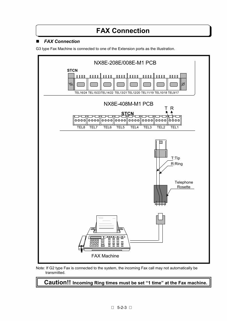
5-2-3
FAX Connection
! FAX Connection
G3 type Fax Machine is connected to one of the Extension ports as the illustration.
Note: If G2 type Fax is connected to the system, the incoming Fax call may not automatically be transmitted.
Caution!! Incoming Ring times must be set “1 time” at the Fax machine.
STCN
STCN
TEL8 TEL7 TEL6 TEL5 TEL4 TEL3 TEL2 TEL1
TEL16/24 TEL15/23TEL14/22 TEL13/21 TEL12/20 TEL11/19 TEL10/18 TEL9/17
NX8E-208E/008E-M1 PCB
NX8E-408M-M1 PCBT R
TelephoneRosette
T:Tip
R:Ring
FAX Machine
5-2-4
Preparation for Attendant Message
Attendant Message allows the extension assigned as an Operator or Manager to record up to 4 outgoingmessage (Maximum 15 seconds each) which are pre-select out of eight types of message. This messageis played when a caller access the DISA.
Refer to the following example message and record your original message depending on yourrequirement.
Message Type When
1.First Greeting Message When the system answered automatically on DISA line.If you connect a Fax, also ask the caller to press Start key inthe message.
Example Message:Thank you for calling. This is Nitsuko Corporation. Ifyou wish to send your Fax Message, please press“START” key now. If you wish to talk, please enter anextension number, Hunt Group number or securitycode.
2.Second Greeting Message Continued from the First Greeting Message.
Used when the first message takes longer than 15 seconds, orto send the same greeting message in another language.
3.Error Message When outside caller failed to dial the Security Code,Extension Number or Hunt Group Number.
Example Message:That is invalid entry. Dial "#" then "∗∗∗∗ " to return toprevious condition.
4.Transfer to OperatorMessage
When the extension does not answer within thepreprogrammed time.
Example Message:Your call will be transferred to operator.
5.Cut-Off Message Before the call is cut off forcibly.
Example Message:This line will be terminated.
6.Automatic TransferMessage (Call Forward)
When the system is set Call Forward on DISA line, thismessage is sent before transferring.
Example Message:Thank you for calling. This call will be transferred.Please wait a moment.
7.First Night Message When the system answered automatically on DISA line,while the system is placed in Night Mode.
Example Message:Thank you for calling. This is Nitsuko Corporation.Our office is closed for today. Please call back again.
8.Second Night Message Continued from the First Night Message.
Used when the first message takes longer than 15 seconds,or to send the same greeting message in another language.

5-2-5
Preparation for Attendant Message
Before Recording the Attendant Message, the user should be selected which types of message arerequired. After select the Message, the Message type(VAU Service Number and VAU Message Number)is assigned by Program #047. The relationship between VAU Service Number (1-8) and VAU MessageNumber (1-4) are as shown bellow;
Example; User selected VAU service number; 1,3,4,5
#047: Select VAU Service Numberfrom 1-8.
#047: VAU Message Number(1-4)
Record Outgoing Message byassign VAU Message Number(#047)
1. 1st DISA Attendant Message 1 930 + Message No.01 + ……
3. DISA Error Message 2 930 + Message No.02 + ……
4. DISA Operator Transfer Message 3 930 + Message No.03 + ……
5. DISA Disconnect Message 4 930 + Message No.04 + ……
Then start the Message Recording/Erasing/Confirming as followings;
1. To Record Attendant Message from No.10 BTXD(TXD) Telephone:
Display Indication Operation and Information
# # S U N # 2 5 # 1 2 : 0 0 P M
R E C . D I S A # M S G # > # #
1. Lift handset or press SPK.2. Dial 930.
# # S U N # 2 5 # 1 2 : 0 0 P M
R E C . D I S A # M S G # > 0 1
3. Dial Message Number (01 to 04).
0 0 : 0 0 : 0 0 # 1 2 : 0 0 P M
R E C . D I S A # M S G # > 0 1
4. Dial *.(Start recording after dial tone.)
0 0 : 0 0 : 0 6 # 1 2 : 0 0 P M
R E C . D I S A # M S G # > 0 1
5. Dial *. (Stop recording.)or dial # to cancel recording.
# # S U N # 2 5 # 1 2 : 0 0 P M
1 0 # # # # # # # # # # # # # #
6. Hang up or press SPK.

5-2-6
Preparation for Attendant Message
2. To Erase Attendant Message from No.10 BTXD(TXD) Telephone:
Display Indication Operation and Information
# # S U N # 2 5 # 1 2 : 0 0 P M
D E L . D I S A # M S G # > # #
1. Lift handset or press SPK.2. Dial 931.
# # S U N # 2 5 # 1 2 : 0 0 P M
D E L . D I S A # M S G # > 0 1
3. Dial Message Number (01 to 04).
# # S U N # 2 5 # 1 2 : 0 0 P M
# # S U N # 2 5 # 1 2 : 0 0 P M
1 0 # # # # # # # # # # # # # #
4. Dial *.(The message shall be erased after confirmation tone.)
5. Hang up or press SPK.
3. To confirm Attendant Message from No.10 BTXD(TXD) Telephone:Display Indication Operation and Information
# # S U N # 2 5 # 1 2 : 0 0 P M
P L Y . D I S A # M S G # > # #
1. Lift handset or press SPK.2. Dial 932.
# # S U N # 2 5 # 1 2 : 0 0 P M
P L Y . D I S A # M S G # > 0 2
3. Dial Message Number (01 to 04).
# # S U N # 2 5 # 1 2 : 0 0 P M
P L Y . D I S A # M S G # > 0 2
4. Dial *.5. The message shall be sent from Handset or Built-
in Speaker.
# # S U N # 2 5 # 1 2 : 0 0 P M
1 0 # # # # # # # # # # # v # #
6. Hang up or press SPK.

5-2-7
Basic Programming
After installing NX8E-VAU-M1 card, the following “Basic Programming” should be done.
Program # 003-Item 1::::DISA Line AssignmentEnter Trunk Line No. to select Enable DISA.
Program # 003-Item 2::::DISA Line Assignment Enter “3” to select Day/Night mode.
Program # 008-Item 1 : Extension Assignment 2 Enter DISA Extension No. to select DISA(“1”).Program # 017-Item 5 : Existence of attendant for DISA Program # 047 : VAU Message Assignment
Enter VAU Service Number (Select from 1-8) to assign VAU Message No.(1-4).
Program # 075-Item 8 : FAX port assignment Enter the FAX connection port Number.
Important Notice
" When the message is recorded, the voice must be loud and clear.
" If the system data is initialized after recording the outgoing messages, the recordedmessage also be erased.
" If there is a FAX call from a FAX machine other than G3 type, which has no CNG signalsending feature, the system transfers the call to the operator due to CNG signal waitingtimer, then the operator can transfer it to the FAX machine by manual operation. However,when both 1st DISA Attendant Message(Max.15 sec.) and 2nd DISA Attendant Message(Max.15 sec.) are used, the FAX call may be disconnected by the originating FAX machinedue to automatic sending timer by the time it is transferred to the operator.

5-2-8
VAU Operation FlowchartThis flowchart shows DISA operations with VAU Message.
If the VAU Message is not set at the Message area, theprocess will be skipped.
Note 1. Unused port should be assigned as DISA port.2. VAU card has 2 talk-paths.3. Refer to the "External Call Forward on the
DISA line".4. Program #066-Item2.5. Program #046, 048.6. Refer to the "Group Hunt".7. Program #017-Item5.8. Calling duration time is defined in "Program
#066-Item5".9. Extension calling time is defined in
“Program#066-Item3”.10. When the FAX port is assigned in
Program #075-Item8, Dial tone shall not besent.
DISA Incoming
External Call Forward
Message(VAU)
Transfer
Empty aDISA Port?
External Callforward Mode?
Night Mode?
1st/2nd NightMessage(VAU)
3
1st/2nd AutoAttendant
Message(VAU)
1 5 NormalIncoming
Dial Tone
Dial, CNG orTimeout?
"#" + Securitycode?
Trunk to Trunk
ExtensionNumber?
"8" + Hunt GPNo.?
Idle Ext.there ?
4
ErrorMessage(VAU)
Busy Tone
Dial # & * ?
1 2
Called Ext.setAbsent Mode?
2 Called Ext. setDND?
Called Ext.Busy?
Call toExtension
Operator there?
Transfer toOperator
Message(VAU)
Call to Operator
Answer or not?
Operator Call?
Transfer toOperator
Message(VAU)
Operator there?
Call to Operator
Answer or not?
Operator Call
3
Cut OffMessage(VAU)
Cut Off
ExtensionAccess
2 6
4
7
3
Not Empty
NoEmpty
Night
Day
Time Out
Dial
CorrectIncorrect
Incorrect
Incorrect Correct
Correct
Yes
Yes
Yes
Yes
Yes
Yes
Yes
Yes Answer
Answer
No
No
No
No
No
No
No
No
No
No
Empty a VAUPath?
Empty
Not Empty
Yes
10
10
Note 1
Note 2
Note 3
Note 4
Note 5
Note 6
Note 9
Note 7
Note 8
Note 8
Note 7
FAXconnected?
FAX Transfer
CNG
2
8
8
Yes
No
If VAU Message is not set at the Message area, theMessage process will be skipped to next.
Note 10

5-2-9
VAU Operation Flowchart
Trunk-to-Trunk
Dial Tone
Idle TrunkLine there?
Dial"9" and LineNo.(01- Max)
Busy Tone
Dial "#" &"*"?
Timeout(Program#066-
Item2)
Queuing GroupNo.
Timeout(Program#066-
Item2)
Dial Tone
Dial?
Dial "#"?
Outside Caller dialTelephone No.
Conversation withoutside Caller
Dial "#" &"*"?
Cut off the 2'nd lineDial "#" & "#"?
Timeout(#031-2)?
Dial Tone
Dial "1" ?
Timeout(#066-Item2)?
Stop Dial Tone
Timeout(#031-1) ?
6
7
A
5
A Yes
Yes
Yes
Yes
Yes
Yes
Yes
Yes
Yes
Yes
No
No
No
No
No
No
No
No
No
No

PART 5-3
System Up Grade

Table of Contents
General Description ..................................................................................................................5-3-1
Required Item ...........................................................................................................................5-3-1
Up-grade the New Software ....................................................................................................5-3-2
5-3-1
General Description
NX8E-ROMU-M1 provides when a User would like to make version up the system software,You can Version Up the system software with simple operation.
Required Item
Required item is as follows;
Required Items QTY Remarks
NX8E-ROMU-M1 Unit with NewVersion ROM
1

5-3-2
Up-grade the New Software
! Open the upper housing of main equipmentStep 1: Power Switch must be turn off.Step 2: Loosen the two screws and remove the upper housing.
! To Up-grade the System software.
Step 1: Check SW1 to “1” side for protect the customer data. Not to ”INT” side.
Step 2: Power switch must be turned off.
Step 3: Insert the ROMU card to the connector labeled ROMCN as the illustration.
NX8E-408M-M1
DHUCN
NX8E-R
OMU-M1
ROMCN
MODCNINT
1
SW
1

5-3-3
Up-grade the New Software
Step 4: Turn the Power switch on.Step 5: The LED1 on the 408M Unit shall be Flashed 3 times for start down load the new software.Step 6: During down load, the LED1 should go off.Step 7: After completed the down load, the LED1 should go on.Step 8: Turn the Power switch off. And the ROMU card takes out from the ROMCN. Step 9: Turn the Power Switch on again for restart the system.
ROMU DHUMODEMU
ETH1 ETH2 CO4 CO3 CO2 CO1 No.17 No.16 No.15 No.14 No.13 No.12 No.11 No.10
Power Supply
CN2
LED1
LED1
Power Switch

Manufacturer:
Nitsuko Corporation2-3 KANDATSUKASA-CHO, CHIYODA-KU, TOKYO 101-8532, JAPANTEL: +81-3-5282-5860 FAX: +81-3-5282-5960
http://www.nitsuko.co.jp/english/overseas/index/
Issue-1.01
June, 2000
Related Documents