Introduction Introduction • An interrupt is an event which informs the CPU that its service (action) is needed. • Sources of interrupts: – internal fault (e.g.. divide by zero, overflow) – software – external hardware : • maskable • nonmaskable – reset

Welcome message from author
This document is posted to help you gain knowledge. Please leave a comment to let me know what you think about it! Share it to your friends and learn new things together.
Transcript
IntroductionIntroduction• An interrupt is an event which informs the
CPU that its service (action) is needed.
• Sources of interrupts:– internal fault (e.g.. divide by zero, overflow)– software– external hardware :
• maskable
• nonmaskable
– reset

Basic Procedure for Processing Basic Procedure for Processing InterruptsInterrupts
• When an interrupt is executed, the p:– finishes executing its current instruction (if any).– saves (PUSH) the flag register, IP and CS register
in the stack.– goes to a fixed memory location.– reads the address of the associated ISR.– Jumps to that address and executes the ISR.– gets (PULL) the flag register, CS:IP register from
the stack.– continues executing the previous job (if any).

8086 Hardware Interrupts pins8086 Hardware Interrupts pins
INTR: Interrupt Request. – Input signal into the CPU– If it is activated, the CPU will finish the current instruction and
respond with the interrupt acknowledge operation– Can be masked (ignored) thru instructions CLI and STI
• NMI: NonMaskable interrupt. – Input signal– Cannot be masked or unmasked thru CLI and STI– Examples of use: power frailer. Memory error
• INTA: Interrupt Acknowledge. – Output signal

Interrupts in Microcomputer Interrupts in Microcomputer SystemsSystems
Interrupts in Microcomputer Systems
• Microcomputer system design requires that I.O devices such as keyboards, displays, sensors and other components receive servicing in an efficient
manner .The most common method of servicing such devices is the Polled approach. This is where the processor must test each device in sequence and in effect ask'' each one if it needs servicing. It is easy to see that a large portion of the main program is looping through this continuous polling cycle and that such a method would have a serious detrimental effect on system throughput, thus limiting the tasks that could be assumed by the microcomputer and reducing the cost effectiveness of using such devices.

Interrupts in Microcomputer Interrupts in Microcomputer SystemsSystems
• A more desirable method would be one that would allow the microprocessor to be executing its main program and only stop to service peripheral devices
when it is told to do so by the device itself. In effect, the method would provide an external asynchronous input that would inform the processor that it should complete whatever instruction that is currently being executed and fetch a new routine that will service the requesting device. Once this servicing is complete, however, the processor would resume exactly where it left off.
• This method is called Interrupt . It is easy to see that system throughput would drastically increase, and thus more tasks could be assumed by the microcomputer to further enhance its cost effectiveness.
• The Programmable Interrupt Controller (PIC) functions as an overall manager in an Interrupt-Driven system environment. It accepts requests from the
peripheral equipment, determines which of the incoming requests is of the highest importance (priority), ascertains whether the incoming request has a
higher priority value than the level currently being serviced, and issues an interrupt to the CPU based on this determination.
Programmable Interrupt Controller (PIC)Programmable Interrupt Controller (PIC)
• 8259 is Programmable Interrupt Controller (PIC)• It is a tool for managing the interrupt requests.
• 8259 is a very flexible peripheral controller chip:– PIC can deal with up to 64 interrupt inputs– interrupts can be masked– various priority schemes can also programmed.
• originally (in PC XT) it is available as a separate IC• Later the functionality of (two PICs) is in the
motherboards chipset.
• In some of the modern processors, the functionality of the PIC is built in.

Pin descriptionPin descriptionCS (CHIP SELECT) :
• A LOW on this input enables the 8259A. No reading or writing of the chip will occur unless the device is selected.
WR (WRITE):
• A LOW on this input enables the CPU to write control words (ICWs and OCWs) to the 8259A.
RD (READ) :
• A LOW on this input enables the 8259A to send the status of the Interrupt Request Register (IRR), In Service Register (ISR), the Interrupt Mask Register (IMR), or the Interrupt level onto the Data Bus.
A0:
• This input signal is used in conjunction with WR and RD signals to write commands into the various command registers, as well as reading the various status registers of the chip. This line can be tied directly to one of the address lines.

Pin descriptionPin descriptionD7 - D0: BIDIRECTIONAL DATA BUS- Control, status and interrupt-vector information is transferred via this bus.CAS0 - CAS2: CASCADE LINES: The CAS lines form a private 8259A bus to control a multiple 8259A structure. These pins are outputs for a master 8259A and inputs for a slave 8259A.SP/EN: SLAVE PROGRAM/ENABLE BUFFER: This is a dual function pin. When in the Buffered Mode it can be used as an output to control buffer transceivers (EN). When not in the buffered mode it is used as an input to designate a master (SP e 1) or slave (SP e 0).INT : INTERRUPT: This pin goes high whenever a valid interrupt request is asserted. It is used to interrupt the CPU, thus it is connected to the CPU's interrupt pin.INTA: INTERRUPT ACKNOWLEDGE: This pin is used to enable 8259A interrupt-vector data onto the data bus by a sequence of interrupt acknowledge pulses issued by the CPU.

Architecture of PIC-8257Architecture of PIC-8257 Features:• It is programmed to work with either 8085 or 8086 processor.• It manage 8-interrupts according to the instructions written into its control registers.• In 8086 processor, it supplies the type number of the interrupt and the type number is
programmable. In 8085 processor, the interrupt vector address is programmable. The priorities of the interrupts are programmable.
• The interrupts can be masked or unmasked individually.• The 8259s can be cascaded to accept a maximum of 64 interrupts.
FUNCTIONAL BLOCK DIAGRAM OF 8259:
It has eight functional blocks. They are:• Control logic • Read Write logic • Data bus buffer • Interrupt Request Register (IRR) • In-Service Register (ISR) • Interrupt Mask Register (IMR) • Priority Resolver (PR) • Cascade buffer.

Architecture of PIC-8259 Architecture of PIC-8259 Data Bus Buffer:
Data bus and its buffer are used for the following activities:
• It is a tristate bidirectional buffer interfaces internal 8259A to the microprocessor system data bus
• The processor sends control word to data bus buffer through D0-D7.
• The processor read status word from data bus buffer through D0-D7
• From the data bus buffer the 8259 send type number through D0-D7 to the processor.
Read/Write control logic
• The function of this block is to accept OUTput commands from the CPU. It contains the Initialization Command Word (ICW) registers and Operation
• Command Word (OCW) registers which store the various control formats for device operation. This function block also allows the status of the 8259A to be transferred onto the Data Bus.

Architecture of PIC-8259 Architecture of PIC-8259 Interrupt request register:• The IRR has eight input lines (IR0-IR7) for interrupts. When these lines go high,
the request is stored in IRR in order to serve them one by one on the priority basis. It registers a request only if the interrupt is unmasked.
• Normally IR0 has highest priority and IR7 has the lowest priority. The priorities of the interrupt request input are also programmable.
• First the 8259 should be programmed by sending Initialization Command Word (ICW) and Operational Command Word (OCW). These command words will inform 8259 about the following:
• Type of interrupt signal (Level triggered / Edge triggered). • Type of processor (8085/8086). • Call address and its interval (4 or 8) • Masking of interrupts. • Priority of interrupts. • Type of end of interrupts.

Architecture of PIC-8259 Architecture of PIC-8259
Interrupt mask register (IMR):• The interrupt mask register (IMR) stores the masking bits of the interrupt lines to be masked.
The relevant information is send by the processor through OCW. In-service register(ISR):• The in-service register keeps track of which interrupt is currently being serviced. Priority resolver:• The priority resolver examines the interrupt request, mask and in-service registers and
determines whether INT signal should be sent to the processor or not. The IR0 has the hiest priority while the IR7 has the lowest priority, normally in fixed priority mode. The priorities however may be altered by the programming the 8259A in rotating mode.
Cascade buffer/comparator:• The cascade buffer/comparator is used to expand the interrupts of 8259. • In cascade connection one 8259 will be directly interrupting 8086 and it is called master
8259. • To each interrupt request input of master 8259 (IR0-IR7), one slave 8259 can be connected.
The 8259s interrupting the master 8259 are called slave 8259s. • Each 8259 has its own addresses so that each 8259 can be programmed independently by
sending command words and independently the status bytes can be read from it.

FIGURE 9-4FIGURE 9-4 Block diagram and pin definitions for the 8259A Programmable Interrupt Controller (PIC). (Courtesy of Intel Corporation.) Block diagram and pin definitions for the 8259A Programmable Interrupt Controller (PIC). (Courtesy of Intel Corporation.)
INTERRUPT SEQUENCEINTERRUPT SEQUENCE
The events occur as follows in an 8086 system:1. One or more of the INTERRUPT REQUEST lines (IR7 – IR0) are raised high, setting the corresponding IRR bit(s).2. The 8259A evaluates these requests, and sends an INT to the CPU, if appropriate.3. The CPU acknowledges the INT and responds with an INTA pulse.4. Upon receiving an INTA from the CPU group, the highest priority ISR bit is set, and the corresponding IRR bit is reset. The 8259A will also release a CALL instruction code (11001101) onto the 8-bit Data Bus through its D7 - D0 pins.5. This CALL instruction will initiate second INTA pulses to be sent to the 8259A from the CPU group.6. This INTA pulse allow the 8259A to release an 8-bit preprogrammed subroutine address onto the Data Bus. 7. ISR bit is reset at the end of the 2nd INTA pulse if automatic EOI mode is programmed
Command words of 8259ACommand words of 8259A
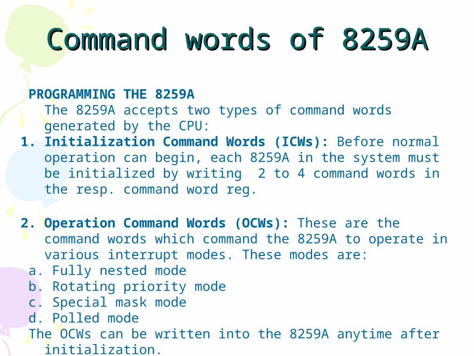
PROGRAMMING THE 8259AThe 8259A accepts two types of command words generated by the CPU:
1. Initialization Command Words (ICWs): Before normal operation can begin, each 8259A in the system must be initialized by writing 2 to 4 command words in the resp. command word reg.
2. Operation Command Words (OCWs): These are the command words which command the 8259A to operate in various interrupt modes. These modes are:
a. Fully nested mode b. Rotating priority mode c. Special mask mode d. Polled mode The OCWs can be written into the 8259A anytime after initialization.

Command words of 8259ACommand words of 8259A
INITIALIZATION COMMAND WORDS(ICWS): Whenever a command is issued with A0 = 0 and D4 = 1, this is
interpreted as Initialization Command Word 1 (ICW1). ICW1 starts the initialization sequence during which the following automatically occur.a.The edge sense circuit is reset, which means that following initialization, an interrupt request (IR) input must make a low-to-high transistion to generate an interrupt.b.The Interrupt Mask Register is cleared.c.IR7 input is assigned priority 7.d.The slave mode address is set to 7.e.Special Mask Mode is cleared and Status Read is set to IRR.f.If IC4 = 0, then all functions selected in ICW4 are set to zero. (Non-Buffered mode*, no Auto EOI, MCS-80, 85 system).

OPERATIONOPERATION• PIC is to be initialized and programmed to control
its operation.
• The operation in simple words:– when an interrupt occurs , the PIC determines the
highest priority, activates the processor via its INTR input, and sends the type number onto the data bus when the processor acknowledges the interrupt.
• Priority:
What is used in PC is fully nested mode. That is the lowest numbered IRQ input has highest priority. Lower priority interrupts will not be forwarded to the processor until the higher priority interrupts have been serviced.

ModesModes
• Fully Nested mode
• Special Fully Nested mode
• Nonspecific Rotating
• Specific Rotating
• Special Mask
• Polling
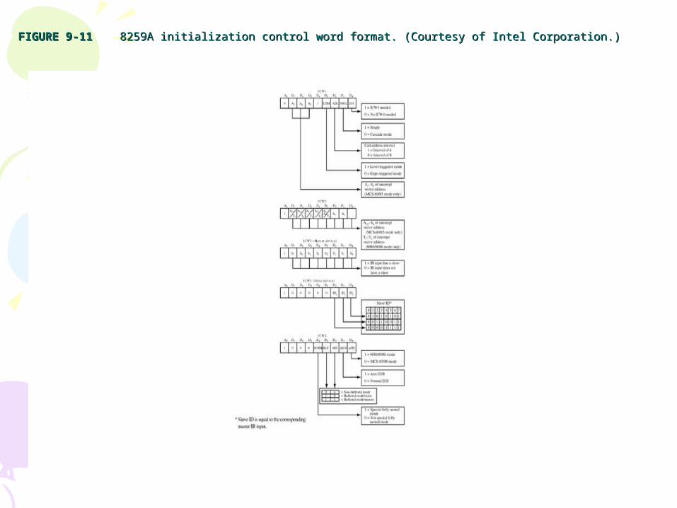
FIGURE 9-11FIGURE 9-11 8259A initialization control word format. (Courtesy of Intel Corporation.) 8259A initialization control word format. (Courtesy of Intel Corporation.)
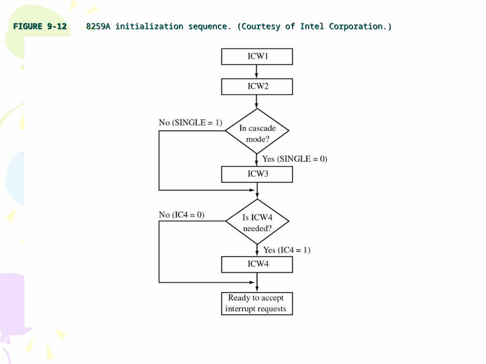
FIGURE 9-12FIGURE 9-12 8259A initialization sequence. (Courtesy of Intel Corporation.) 8259A initialization sequence. (Courtesy of Intel Corporation.)

FIGURE 9-13FIGURE 9-13 8259A operation control word format. (Courtesy of Intel Corporation.) 8259A operation control word format. (Courtesy of Intel Corporation.)
John UffenbeckThe 80x86 Family: Design, Programming, and Interfacing, 3e
Copyright ©2002 by Pearson Education, Inc.Upper Saddle River, New Jersey 07458
All rights reserved.

DMADMA• Direct Memory Access.• In memory-memory or memory-peripherals communication, the
processor is a “middleman” which is not really needed.
• Used with HOLD HOLDA signals.
• DMA requires another processor - The DMA Controller or DMAC- to generate the memory and I/O addresses.
• 8237 is a DMAC.
• In IBM PC, 8237 was used to speed up the read or write operation by the slow 8088 processor.
• Nowadays, It is usually used by sound cards and by memory controllers to generate row address for refreshing.
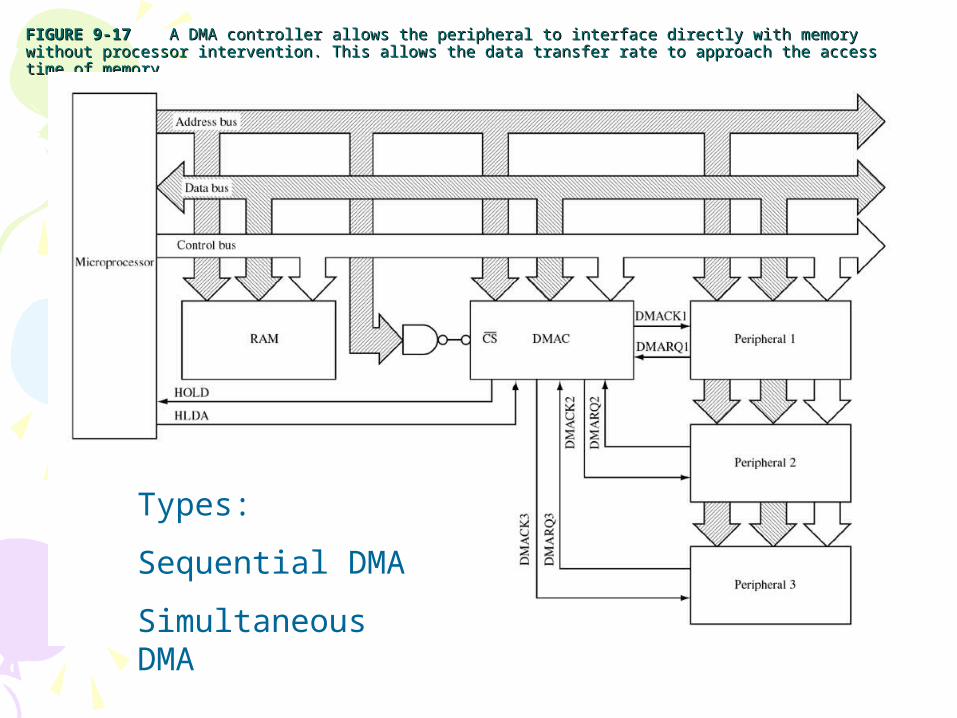
FIGURE 9-17FIGURE 9-17 A DMA controller allows the peripheral to interface directly with memory without processor intervention. This allows the A DMA controller allows the peripheral to interface directly with memory without processor intervention. This allows the data transfer rate to approach the access time of memory.data transfer rate to approach the access time of memory.
Types:
Sequential DMA
Simultaneous DMA
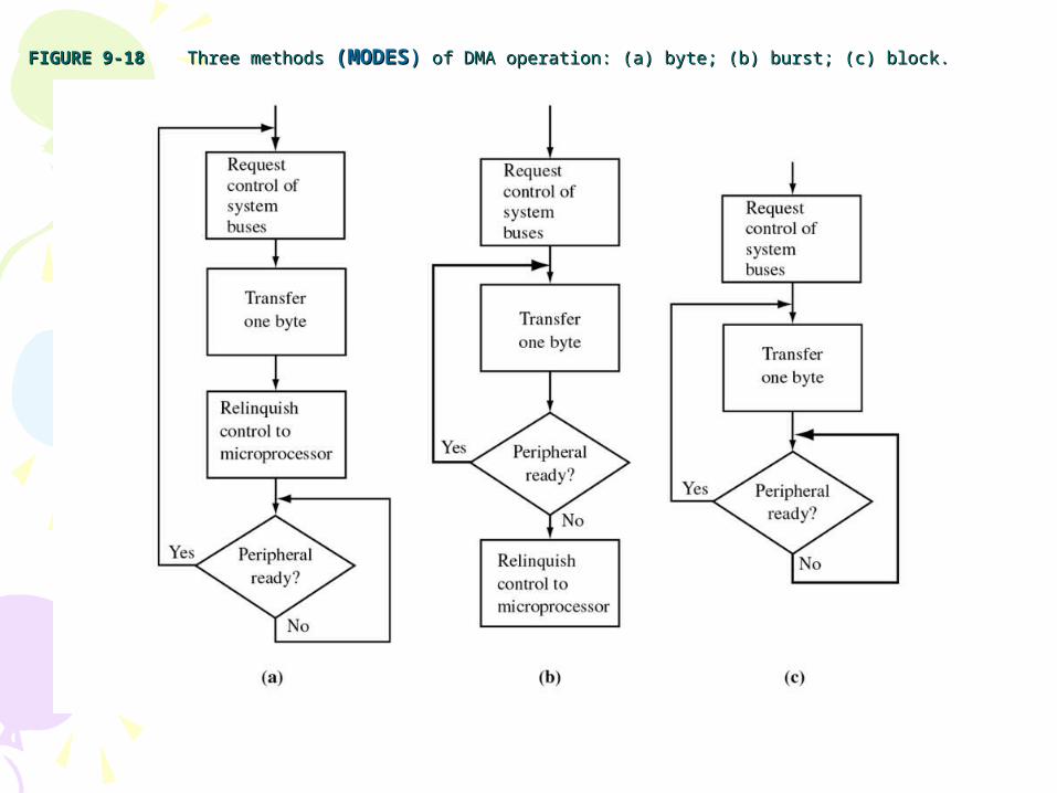
FIGURE 9-18FIGURE 9-18 Three methods Three methods (MODES(MODES)) of DMA operation: (a) byte; (b) burst; (c) block. of DMA operation: (a) byte; (b) burst; (c) block.

I/O summaryI/O summaryThree ways to synchronize the processor to data rate
of peripherals:
1- Polling: which provides a fast response but it the processor recourses are dedicated to one peripheral.
2- Interrupt approach: is much more efficient. the processor only services the peripheral when data is required. requires high software overhead.
3-DMA is a third solution but it increases the complexity of the hardware system.
Related Documents