® ServeRAID M5110 SAS/SATA Controller for IBM System x USER’S GUIDE

Welcome message from author
This document is posted to help you gain knowledge. Please leave a comment to let me know what you think about it! Share it to your friends and learn new things together.
Transcript

®
ServeRAID M5110 SAS/SATA Controller for IBM System x
USER’SGUIDE

ii
First Edition (March 2012)
© Copyright International Business Machines Corporation 2012.
US Government Users Restricted Rights – Use, duplication or disclosure restricted by GSA ADP Schedule Contract with IBM Corp.

ServeRAID M5110 SAS/SATA Controller for IBM System x User’s Guide iii
Preface
This book contains installation instructions and specifications for the ServeRAID M5110 SAS/SATA Controller for IBM® System x®.
For details on how to configure the storage controller, refer to the ServeRAID-M Software User’s Guide. For information about the operating system drivers, refer to the ServeRAID-M Device Driver Installation User’s Guide.
Organization
This document has the following chapters and appendices:
Chapter 1, Overview, provides a general overview of the ServeRAID M5110 SAS/SATA controller.
Chapter 2, ServeRAID Controller Hardware Installation, describes the procedures for installing the ServeRAID M5110 SAS/SATA controller.
Chapter 3, ServeRAID M5110 SAS/SATA Controller Characteristics, provides the characteristics and technical specifications for the ServeRAID M5110 SAS/SATA controller.
Appendix A, Getting Help and Technical Assistance, explains how to get help and technical assistance with your ServeRAID products.
Appendix B, Notices , contains information about warranties, trademarks, particulate contamination, and electronic emission notices.
Appendix C, Glossary of Terms and Abbreviations, lists and explains the terms and abbreviations used in this manual.

iv Preface
Related Publications
ServeRAID-M Device Driver Installation User’s Guide
This document explains how to install the ServeRAID-M device driver for your operating system. The information in this document is independent of the back-end bus and applies to the ServeRAID-M controllers.
ServeRAID-M Software User’s Guide
This document explains how to use the MegaRAID Storage Manager and WebBIOS configuration utilities to configure, monitor, and maintain the ServeRAID-M controller and the storage-related devices connected to the controller.
ServeRAID MegaCLI User’s Guide
This document explains how to use the MegaCLI (Command Line Interface) utility to configure, monitor, and maintain the ServeRAID-M controller and the storage-related devices connected to the controller.
Safety Information
This document contains translated caution and danger statements. Each caution and danger statement that appears in the documentation has a number that you can use to locate the corresponding statement in your language in the Safety Information document.
Notices and Statements
The caution and danger statements in this document are also in the multilingual Safety Information document, which is on the IBM Documentation CD. Each statement is numbered for reference to the corresponding statement in your language in the Safety Information document.
The following notices and statements are used in this document:
Note: These notices provide important tips, guidance, or advice.

Preface v
Important: These notices provide information or advice that might help you avoid inconvenient or problem situations.
Attention: These notices indicate potential damage to programs, devices, or data. An attention notice is placed just before the instruction or situation in which damage might occur.
CAUTION: These statements indicate situations that can be potentially hazardous to you. A caution statement is placed just before the description of a potentially hazardous procedure, step, or situation.
DANGER: These statements indicate situations that can be poten-tially lethal or extremely hazardous to you. A danger statement is placed just before the description of a potentially lethal or extremely hazardous procedure step or situation.
Safety
Use the following safety guidelines to help protect your computer system from potential damage and to ensure your own personal safety.
Note: Use your ServeRAID M5110 SAS/SATA controller with UL-listed Information Technology Equipment (ITE) products only.

vi Preface

Preface vii
Protecting against Electrostatic Discharge – Static electricity can harm delicate components inside your computer. To prevent static damage, discharge static electricity from your body before you touch any of your computer’s electronic components, such as the microprocessor. You can do so by touching an unpainted metal surface, such as the metal around the card-slot openings at the back of the computer.
As you continue to work inside the computer, periodically touch an unpainted metal surface to remove any static charge your body may have accumulated. In addition to the preceding precautions, you can also take the following steps to prevent damage from electrostatic discharge:
When unpacking a static-sensitive component from its shipping carton, do not remove the component from the antistatic packing material until you are ready to install the component in your computer. Just before unwrapping the antistatic packaging, be sure to discharge static electricity from your body.
When transporting a sensitive component, first place it in an antistatic container or packaging.
Handle all sensitive components in a static-safe area. If possible, use antistatic floor pads and workbench pads.

viii Preface
ServeRAID M5110 SAS/SATA Controller for IBM System x User’s Guide ix
Contents
Chapter 1 Overview1.1 Overview 1-11.2 ServeRAID M5110 Controller Description and Limitations 1-2
1.2.1 Controller Limitations 1-41.3 Integrated MegaRAID Mode and MegaRAID Mode 1-4
1.3.1 Supported RAID Level Upgrades 1-51.3.2 Summary of RAID Levels 1-6
1.4 Configuration Scenarios 1-71.4.1 Number of Physical Disks Supported 1-9
1.5 Benefits of the SAS Interface 1-101.5.1 PCI Express Architecture 1-111.5.2 Operating System Support 1-11
1.6 Benefits of the ServeRAID M5110 SAS/SATA Controller 1-111.6.1 SAS Features 1-121.6.2 SAS Array Limitations 1-131.6.3 SATA III Features 1-141.6.4 PCI Express Performance 1-141.6.5 Usability Features 1-151.6.6 Flexibility Features 1-151.6.7 Drive Roaming 1-161.6.8 Drive Migration 1-171.6.9 New Drives Attached to a ServeRAID Controller 1-181.6.10 Automatic Rebuilds on New Drives 1-191.6.11 System (JBOD) Drives 1-19
1.7 Hardware Specifications 1-201.8 Technical Support 1-21
x Contents
Chapter 2 ServeRAID Controller Hardware Installation2.1 Requirements 2-12.2 Quick Installation 2-22.3 Detailed Installation 2-22.4 Connecting a ServeRAID-M5110 SAS/SATA Controller to a Drive
Backplane on an Enclosure 2-62.5 After Installing the Controller 2-7
Chapter 3ServeRAID M5110 SAS/SATA Controller Characteristics
3.1 ServeRAID M5110 SAS/SATA Controller Descriptions 3-13.1.1 Board Layout and Connector Information 3-1
3.2 Characteristics of the ServeRAID M5110 SAS/SATA Controller3-5
3.3 Technical Specifications 3-63.3.1 Controller Specifications 3-63.3.2 Array Performance Features 3-73.3.3 Fault Tolerance 3-83.3.4 Power Supply Requirements for the ServeRAID M5110
SAS/SATA Controller 3-83.3.5 Operating and Non-operating Conditions 3-93.3.6 Safety Characteristics 3-9
Appendix A Getting Help and Technical AssistanceA.1 Before you call A-2A.2 Using the documentation A-3A.3 Getting help and information from the World Wide Web A-3A.4 How to send Dynamic System Analysis data to IBM A-3A.5 Creating a personalized support web page A-4A.6 Software service and support A-4A.7 Hardware service and support A-4A.8 IBM Taiwan product service A-5
Appendix B NoticesB.1 Trademarks B-2B.2 Important Notes B-3
Contents xi
B.3 Particulate contamination B-4B.4 Documentation format B-5B.5 Telecommunication regulatory statement B-5B.6 Electronic emission notices B-5
Appendix C Glossary of Terms and Abbreviations

xii Contents

Contents xiii
Figures1.1 Example of a SAS Direct-Connect Application 1-81.2 Example of a ServeRAID Controller Configured with an Expander
1-92.1 ServeRAID M5110 Controller Installation in a PCI Express Slot
2-42.2 Connecting a ServeRAID M5110 Controller Internal Connector to
a Drive Backplane 2-73.1 Card Layout for the ServeRAID M5110 SAS/SATA Controller3-2

xiv Contents

Contents xv
Tables1.1 Physical Devices Required for Each RAID Level 1-91.2 ServeRAID M5110 SAS/SATA Controller Array Limitations 1-131.3 ServeRAID M5110 SAS/SATA Controller Specifications 1-203.1 ServeRAID M5110 SAS/SATA Controller Connectors 3-23.2 ServeRAID M5110 SAS/SATA Controller Characteristics 3-53.3 ServeRAID M5110 SAS/SATA Controller Specifications 3-63.4 Array Performance Features 3-73.5 Fault Tolerance Features 3-83.6 Power Supply for the ServeRAID M5110 SAS/SATA Controller
3-9

xvi Contents

ServeRAID M5110 SAS/SATA Controller for IBM System x User’s Guide 1-1
Chapter 1 Overview
This chapter provides a general overview of the ServeRAID M5110 SAS/SATA controller, which has RAID control capabilities. It consists of the following sections:
Section 1.1, “Overview”
Section 1.2, “ServeRAID M5110 Controller Description and Limitations”
Section 1.3, “Integrated MegaRAID Mode and MegaRAID Mode”
Section 1.4, “Configuration Scenarios”
Section 1.5, “Benefits of the SAS Interface”
Section 1.6, “Benefits of the ServeRAID M5110 SAS/SATA Controller”
Section 1.7, “Hardware Specifications”
Section 1.8, “Technical Support”
1.1 Overview
The ServeRAID M5110 Serial Attached SCSI (SAS)/Serial ATA (SATA) controller is a high-performance intelligent PCI Express-to-SAS/SATA controllers with RAID control capabilities. This controller provides reliability, high performance, and fault-tolerant disk subsystem management.
The ServeRAID M5110 SAS/SATA controller is a versatile controller that provides the backbone of server environments. It is an ideal RAID solution for the storage of workgroup, departmental, and enterprise systems. This controller offers a cost-effective way to implement RAID in a server.

1-2 Overview
The ServeRAID M5110 controller is based on the MegaRAID first-to-market SAS IC technology and proven technology. As a second-generation PCI Express controller, it addresses the growing demand for increased data throughput and scalability requirements across midrange and enterprise-class server platforms. IBM offers a family of SAS controller to address the needs for both internal solutions and external solutions.
SAS technology brings a wealth of options and flexibility with the use of SAS devices and SATA devices within the same storage infrastructure. However, SAS devices and SATA devices bring individual characteristics that make each one a more suitable choice depending on your storage needs. MegaRAID gives you the flexibility to combine these two similar technologies on the same controller and within the same enclosure.
1.2 ServeRAID M5110 Controller Description and Limitations
The ServeRAID M5110 SAS/SATA controller is a PCI-Express 3.0, half-size, half-height RAID controller based on the LSISAS2208 PCI Express-SAS/SATA I/O Processor chip.
The controller controls eight internal 6-Gb/s SAS/SATA ports through two SFF-8087 x4 internal mini SAS connectors. The controller integrates eight high-performance SAS/SATA PHYs and a PCI Express bus master DMA core. Each of the eight PHYs is capable of 6.0 Gb/s SAS link rates and 6.0 Gb/s SATA III link rates.
The ServeRAID M5110 controller brings 6.0 Gb/s Serial Attached SCSI and 6.0 Gb/s Serial ATA performance to host controller, workstation, and server designs. The controller supports internal storage devices, which allows you to use a system that supports enterprise-class SAS drives, and desktop-class SATA drives. The controller can connect to drives directly. Simplified cabling between devices is an additional benefit.
The controller is based on the LSISAS2208 ROC device. This device is compliant with the Fusion-MPT architecture and provides a PCI Express x8 interface.
The LSISAS2208 ROC device provides an eight-lane, 8-GT/s (1GB/s) PCI Express host interface, eight 6.0 Gb/s SAS ports or eight 6.0 Gb/s SATA ports, and a full-featured, hardware-based RAID implementation.

ServeRAID M5110 Controller Description and Limitations 1-3
The LSISAS2208 ROC device provides the maximum benefits of a RAID system and enables you to configure the system to satisfy your system requirements.
The LSISAS2208 ROC device increases system performance and provides fault-tolerant data storage. The LSISAS2208 supports data striping across multiple disks, which reduces disk access time because multiple disks simultaneously read or write data. In addtion, the LSISAS2208 ROC device backs up data with either data mirroring or a parity block. Either backup method enables you to recover lost data in the event of a disk failure. You can select the data backup method that best suits your needs. A hardware RAID assist exclusive-OR (XOR) engine speeds parity generation and checking and reduces system-access times.
The controller supports the SAS protocol as described in the Serial Attached SCSI Standard, version 2.0, and the SATA III protocol defined by the Serial ATA Revision 3.0 Specification.
Note: You cannot mix SAS drives and SATA drives within the same virtual drive(s).
Each port on the controller supports SAS devices and/or SATA devices using the following:
SAS Serial SCSI Protocol (SSP), which enables communication with other SAS devices
SATA, which enables communication with other SATA devices
Serial Management Protocol (SMP), which communicates topology management information directly with an attached SAS expander device
Serial Tunneling Protocol (STP), which enables communication with a SATA device through an attached expander

1-4 Overview
1.2.1 Controller Limitations
The ServeRAID M5110 controller has the following limitations:
You can connect only one device per SAS PHY unless you use an expander
You can use a maximum cable length of six feet (using shorter cables is preferred)
Cables have to meet the SAS specification
You cannot mix SAS drives and SATA drives in the same virtual drive
You cannot mix SAS Solid State Drives (SSDs) or SATA SSDs and legacy mechanical drives (SAS or SATA) in the same virtual drive
You cannot mix Solid State SAS drives and Solid State SATA drives in the same virtual drive
See Section 3.3.4, “Power Supply Requirements for the ServeRAID M5110 SAS/SATA Controller,” for information about the power requirements, and Section 3.3.5, “Operating and Non-operating Conditions” for information about the minimum and the maximum temperature ranges.
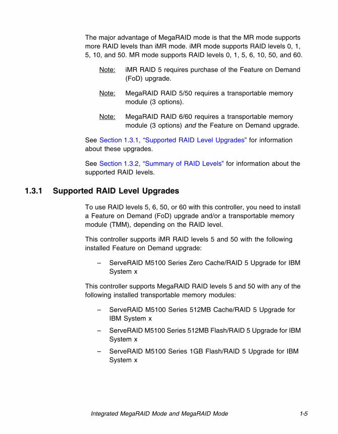
1.3 Integrated MegaRAID Mode and MegaRAID Mode
You can run this ServeRAID SAS/SATA controller in either integrated MegaRAID (iMR) mode or in MegaRAID (MR) mode.
Integrated MegaRAID is a highly integrated, low-cost RAID solution made possible by Fusion-MPT™ architecture. Integrated MegaRAID is a processor-based, hardware RAID solution designed for system environments requiring redundancy and high availability where a full-featured RAID implementation is not desired or might be cost prohibitive.
The major advantage of Integrated MegaRAID is that iMR provides RAID at the processor level, so it does not burden the CPU, which allows for more efficient operation.
Integrated MegaRAID Mode and MegaRAID Mode 1-5
The major advantage of MegaRAID mode is that the MR mode supports more RAID levels than iMR mode. iMR mode supports RAID levels 0, 1, 5, 10, and 50. MR mode supports RAID levels 0, 1, 5, 6, 10, 50, and 60.
Note: iMR RAID 5 requires purchase of the Feature on Demand (FoD) upgrade.
Note: MegaRAID RAID 5/50 requires a transportable memory module (3 options).
Note: MegaRAID RAID 6/60 requires a transportable memory module (3 options) and the Feature on Demand upgrade.
See Section 1.3.1, “Supported RAID Level Upgrades” for information about these upgrades.
See Section 1.3.2, “Summary of RAID Levels” for information about the supported RAID levels.
1.3.1 Supported RAID Level Upgrades
To use RAID levels 5, 6, 50, or 60 with this controller, you need to install a Feature on Demand (FoD) upgrade and/or a transportable memory module (TMM), depending on the RAID level.
This controller supports iMR RAID levels 5 and 50 with the following installed Feature on Demand upgrade:
– ServeRAID M5100 Series Zero Cache/RAID 5 Upgrade for IBM System x
This controller supports MegaRAID RAID levels 5 and 50 with any of the following installed transportable memory modules:
– ServeRAID M5100 Series 512MB Cache/RAID 5 Upgrade for IBM System x
– ServeRAID M5100 Series 512MB Flash/RAID 5 Upgrade for IBM System x
– ServeRAID M5100 Series 1GB Flash/RAID 5 Upgrade for IBM System x

1-6 Overview
This controller supports MegaRAID RAID levels 6 and 60 with any of the following installed transportable memory modules and the Feature on Demand upgrade:
– ServeRAID M5100 Series 512MB Cache/RAID 5 Upgrade for IBM System x
– ServeRAID M5100 Series 512MB Flash/RAID 5 Upgrade for IBM System x
– ServeRAID M5100 Series 1GB Flash/RAID 5 Upgrade for IBM System x
– ServeRAID M5100 Series RAID 6 Upgrade for IBM System x (FoD)
1.3.2 Summary of RAID Levels
RAID levels describe a system for ensuring the availability and redundancy of data stored on large disk subsystems.
RAID 0 uses striping to provide high data throughput, especially for large files in an environment that does not require fault tolerance.
RAID 1 uses mirroring so that data written to one drive is simultaneously written to another drive. This is good for small databases or other applications that require small capacity but complete data redundancy.
RAID 5 uses disk striping and parity data across all drives (distributed parity) to provide high data throughput, especially for small random access.
RAID 6 uses distributed parity, with two independent parity blocks per stripe, and disk striping. A RAID 6 virtual drive can survive the loss of two drives without losing data. A RAID 6 drive group, which requires a minimum of three drives, is similar to a RAID 5 drive group. Blocks of data and parity information are written across all drives. The parity information is used to recover the data if one or two drives fail in the drive group.
RAID 10, a combination of RAID 0 and RAID 1, consists of striped data across mirrored spans. A RAID 10 drive group is a spanned drive group that creates a striped set from a series of mirrored drives. RAID 10 allows a maximum of eight spans. You must use an even number of

Configuration Scenarios 1-7
drives in each RAID virtual drive in the span. The RAID 1 virtual drives must have the same stripe size. RAID 10 provides high data throughput and complete data redundancy but uses a larger number of spans.
RAID 50, a combination of RAID 0 and RAID 5, uses distributed parity and disk striping. A RAID 50 drive group is a spanned drive group in which data is striped across multiple RAID 5 drive groups. RAID 50 works best with data that requires high reliability, high request rates, high data transfers, and medium-to-large capacity.
RAID 60, a combination of RAID 0 and RAID 6, uses distributed parity, with two independent parity blocks per stripe in each RAID set, and disk striping. A RAID 60 virtual drive can survive the loss of two drives in each of the RAID 6 sets without losing data. It works best with data that requires high reliability, high request rates, high data transfers, and medium-to-large capacity.
Note: Having virtual drives of different RAID levels, such as RAID 0 and RAID 5, in the same drive group is not allowed. For example, if an existing RAID 5 virtual drive is created out of partial space in an array, the next virtual drive in the array has to be R5 only.
1.4 Configuration Scenarios
There are two main scenarios in which you can use this ServeRAID controller:
Low-end, internal SATA configuration: In this configuration, use the ServeRAID controller as a high-end SATA compatible controller that connects to several SATA disks. This type of configuration is mostly for low-end or entry servers. Enclosure management is provided through out-of-band I2C bus. Side bands of both types of internal SAS connectors support the SFF-8485 (SGPIO) interface.
Midrange, internal SAS configuration: This configuration is like the internal SATA configuration, but with high-end disks. This type of configuration is more suitable for low-range to midrange servers.
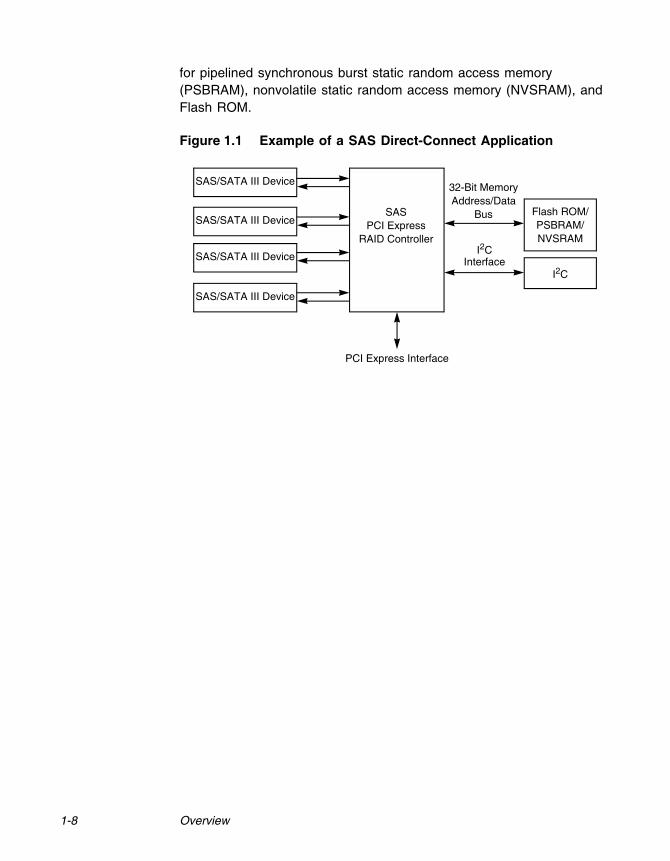
The following figure shows a direct-connect configuration. The Inter-IC (I2C) interface communicates with peripherals. The external memory bus provides a 32-bit memory bus, parity checking, and chip select signals
1-8 Overview
for pipelined synchronous burst static random access memory (PSBRAM), nonvolatile static random access memory (NVSRAM), and Flash ROM.
Figure 1.1 Example of a SAS Direct-Connect Application
Flash ROM/SASPCI Express
RAID Controller
SAS/SATA III Device 32-Bit MemoryAddress/Data
BusPSBRAM/
I2C
SAS/SATA III Device
SAS/SATA III Device
SAS/SATA III Device
PCI Express Interface
NVSRAMI2C
Interface

Configuration Scenarios 1-9
The following figure shows an example of a ServeRAID controller configured with an expander that is connected to SAS disks, SATA disks, or both.
Figure 1.2 Example of a ServeRAID Controller Configured with an Expander
1.4.1 Number of Physical Disks Supported
Your configuration planning for your ServeRAID controller depends in part on the number of physical disks that you want to use in a RAID array. The number of drives in an array determines the RAID levels that can be supported by this controller. Only one RAID level can be assigned to each virtual disk. Table 1.1 shows the minimum number and the maximum number of drives required for each RAID level.
Expander
Flash ROM/NVSRAM/
SRAM
I2C/UART
Expander
SAS/SATA IIIDrives
PCI Express Interface
SAS/SATADrives
SAS/SATA IIIDrives
SAS/SATA IIIDrives
SAS/SATA IIIDrives
8
SRAMSRAMSDRAM
PeripheralBus
72-bit DDR/DDR2with ECCInterface
PCI Express to SAS ROC
SAS RAID Controller
Table 1.1 Physical Devices Required for Each RAID Level
RAID Level
Minimum # of Physical Devices
Maximum # of Physical Devices
0 1 32
1 2 2
5 3 32
1-10 Overview
1.5 Benefits of the SAS Interface
SAS is a serial, point-to-point, enterprise-level device interface that leverages the proven SCSI protocol set. SAS combines the advantages of SATA, SCSI, and Fibre Channel, and is the future mainstay of the enterprise and high-end workstation storage markets. SAS offers a higher bandwidth per pin than parallel SCSI, and it improves signal and data integrity.
The SAS interface uses the proven SCSI command set to ensure reliable data transfers, while providing the connectivity and flexibility of point-to-point serial data transfers. The serial transmission of SCSI commands eliminates clock-skew challenges. The SAS interface provides improved performance, simplified cabling, smaller connectors, lower pin count, and lower power requirements when compared to parallel SCSI.
The ServeRAID M5110 SAS/SATA controller leverages a common electrical and physical connection interface that is compatible with Serial ATA technology. The SAS protocols and SATA protocols use a thin, 7-wire connector instead of the 68-wire SCSI cable or 26-wire ATA cable. The SAS/SATA III connector and cable are easier to manipulate, allow connections to smaller devices, and do not inhibit airflow. The point-to-point SATA III architecture eliminates inherent difficulties created by the legacy ATA master-slave architecture, while maintaining compatibility with existing ATA firmware.
6 3 32
10 4 32
50 6 32
60 6 32
Table 1.1 Physical Devices Required for Each RAID Level (Cont.)
RAID Level
Minimum # of Physical Devices
Maximum # of Physical Devices
Benefits of the ServeRAID M5110 SAS/SATA Controller 1-11
1.5.1 PCI Express Architecture
PCI Express is a local bus system designed to increase data transfers without slowing down the central processing unit (CPU). You can install your ServeRAID M5110 controller PCI Express SAS/SATA controller in PCI Express computer systems with a standard bracket type. With this controller in your system, you can connect SCSI devices and SATA devices over the bus.
PCI Express goes beyond the PCI specification in that it is intended as a unifying I/O architecture for various systems: desktops, workstations, mobile, server, communications, and embedded devices.
1.5.2 Operating System Support
To check for the latest list of supported operating systems and to download the drivers for those operating systems, see http://www.ibm.com/systems/support/.
The ServeRAID M5110 controller uses Fusion-MPT™ architecture for all major operating systems, thinner drivers, and better performance.
1.6 Benefits of the ServeRAID M5110 SAS/SATA Controller
This section provides a summary of the features and the benefits of the ServeRAID M5110 SAS/SATA controller. It contains information on SAS features, SATA features, PCI performance, integration, usability, and flexibility.
The controller offers the following features:
PCI Express x8 lane width
PCI Express performance up to 8 GT/s (1 GB/s) per lane
Two internal connectors
Support for RAID levels 0, 1, 5, 10, and 50 in iMR mode
Support for RAID levels 0, 1, 5, 6, 10, 50, and 60 in MR mode
Note: To use RAID levels 5/50/6/60 with this controller, you need to install a Feature on Demand (FoD) upgrade and/or a
1-12 Overview
transportable memory module (TMM). See Section 1.3.1, “Supported RAID Level Upgrades” for information about these upgrades.
Advanced array configuration and management utilities
Online RAID level migration
Drive migration
Drive roaming
Media scan
No reboot necessary after expansion
More than 200 Qtags per array
User-specified rebuild rate
32-Kbyte nonvolatile random access memory (NVRAM) for storing RAID system configuration information; the MegaRAID SAS firmware is stored in flash ROM for easy upgrade.
1.6.1 SAS Features
The following list describes the SAS features of the ServeRAID M5110 controller:
Provides eight fully independent PHYs
Supports 6.0 Gb/s SAS data transfers per PHY
Supports SSP to enable communication with other SAS devices
Supports SMP to communicate topology management information
Provides a serial, point-to-point, enterprise-level storage interface
Simplifies cabling between devices
Supports wide ports consisting of 2, 3, or 4 PHYs within a single quad port
Supports narrow ports consisting of a single PHY
Transfers data using SCSI information units
Benefits of the ServeRAID M5110 SAS/SATA Controller 1-13
1.6.2 SAS Array Limitations
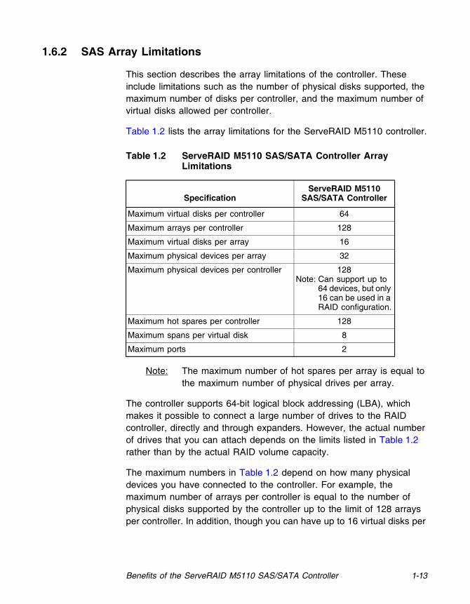
This section describes the array limitations of the controller. These include limitations such as the number of physical disks supported, the maximum number of disks per controller, and the maximum number of virtual disks allowed per controller.
Table 1.2 lists the array limitations for the ServeRAID M5110 controller.
Note: The maximum number of hot spares per array is equal to the maximum number of physical drives per array.
The controller supports 64-bit logical block addressing (LBA), which makes it possible to connect a large number of drives to the RAID controller, directly and through expanders. However, the actual number of drives that you can attach depends on the limits listed in Table 1.2 rather than by the actual RAID volume capacity.
The maximum numbers in Table 1.2 depend on how many physical devices you have connected to the controller. For example, the maximum number of arrays per controller is equal to the number of physical disks supported by the controller up to the limit of 128 arrays per controller. In addition, though you can have up to 16 virtual disks per
Table 1.2 ServeRAID M5110 SAS/SATA Controller Array Limitations
SpecificationServeRAID M5110
SAS/SATA Controller
Maximum virtual disks per controller 64
Maximum arrays per controller 128
Maximum virtual disks per array 16
Maximum physical devices per array 32
Maximum physical devices per controller 128Note: Can support up to
64 devices, but only 16 can be used in a RAID configuration.
Maximum hot spares per controller 128
Maximum spans per virtual disk 8
Maximum ports 2
1-14 Overview
array, and up to 128 arrays per controller, there is a limit of 64 virtual disks per controller.
1.6.3 SATA III Features
The following list describes the SATA III features of the ServeRAID ServeRAID M5110 controller:
Supports SATA III data transfers of 6.0 Gb/s
Supports STP data transfers of 3.0 Gb/s
Provides a serial, point-to-point storage interface
Simplifies cabling between devices
Eliminates the master-slave construction used in parallel ATA
Allows addressing of multiple SATA III targets through an expander
Allows multiple initiators to address a single target (in a fail-over configuration) through an expander
Displays activity and fault indicators for each PHY
Supports Port Selector (for dual-port drives)
Each port on the controller supports SAS devices, SATA devices, or both using SSP, SMP, STP, and SATA. SSP enables communication with other SAS devices.
Enables the controller to communicate with other SATA devices.
Supports staggered spin-up
Supports hot plug
1.6.4 PCI Express Performance
The following list describes the PCI Express performance features of the ServeRAID M5110 controller:
Provides a PCI Express 3.0 interface that:
– Supports a dedicated PCI Express bus
– Supports x8 lane configuration
– Supports transfer rates of up to 8 GT/s (1 GB/s) per lane
– Complies with the PCI Express Specification, Revision 3.0
Benefits of the ServeRAID M5110 SAS/SATA Controller 1-15
Provides unequaled performance through the Fusion-MPT architecture
Provides high throughput and low CPU utilization to offload the host processor
1.6.5 Usability Features
The following list describes the usability features of the ServeRAID M5110 controller:
Simplifies cabling with point-to-point, serial architecture
Supports smaller, thinner cables that do not restrict airflow
Provides drive spin-up sequencing control
Provides up to two LED signals for each PHY to indicate link activity and faults
Provides an I2C interface for enclosure management
Supports the external SAS Sideband signal SFF-8485 (SGPIO) interface
1.6.6 Flexibility Features
These features increase the flexibility of the ServeRAID M5110 controller:
Supports a Flash ROM interface, a nonvolatile static RAM (NVSRAM) interface, and a pipelined synchronous burst SRAM (PSBRAM) interface
Offers a flexible programming interface to tune I/O performance
Allows mixed connections to SAS targets or SATA III targets
Leverages compatible connectors for SAS connections and SATA III connections
Allows grouping of up to four PHYs in a single quad port to form a wide port
Allows programming of the World Wide Name

1-16 Overview
1.6.7 Drive Roaming
Drive roaming occurs when the physical disks are changed to different ports on the same controller. When the drives are placed on different channels, the controller detects the RAID configuration from the configuration data on the drives.
Note: In a clustering environment, drive roaming is supported within the same channel only.
Configuration data is saved in both the NVRAM on the RAID controller and on the drives attached to the controller. This action maintains the integrity of the data on each drive, even if the drives have changed their target ID.
Note: If you move a drive that is being rebuilt, the rebuild operation restarts; it does not resume from where the rebuild operation stopped.
Follow these steps to use drive roaming:
Step 1. Turn off the power to the server and all physical disks, enclosures, and system components. Disconnect the power cords from the system.
Step 2. Open the host system by following the instructions in the host system technical documentation.
Step 3. Move the drives to different positions on the backplane to change the targets.
Step 4. Determine the SAS target requirements.
Step 5. Perform a safety check.
a. Make sure that the drives are inserted correctly.
b. Close the cabinet of the host system.
Step 6. Reconnect the power cords to the system.
Step 7. Turn on the power to the system.
The controller then detects the RAID configuration from the configuration data on the drives.

Benefits of the ServeRAID M5110 SAS/SATA Controller 1-17
1.6.8 Drive Migration
Drive migration is the transfer of a set of drives in an existing configuration from one controller to another. The drives must remain on the same channel and must be reinstalled in the same order as in the original configuration. The controller to which you migrate the drives cannot have an existing configuration.
Note: Only whole virtual disks can be migrated automatically; partial virtual disks can be migrated manually.
Note: Drive roaming and drive migration cannot be supported at the same time.
Follow these steps to migrate drives:
Step 1. Make sure that you clear the configuration on the system to which you migrate the drives, to prevent a configuration data mismatch between the drives and the NVRAM.
Note: When you migrate drives, move only the disks that make up the virtual disk (not all of the physical disks in an array), so that you do not have an NVRAM mismatch error (providing a configuration is on the destination controller). The NVRAM mismatch error appears only if you move all of the drives to the other controller.
Step 2. Turn off the power to the server and all physical disks, enclosures, and system components. Disconnect the power cords from the systems.
Step 3. Open the host system, following the instructions in the host system technical documentation.
Step 4. Remove the SAS cable connectors from the internal drives that you want to migrate.
a. Make sure that pin 1 on the cable matches pin 1 on the connector.
b. Make sure that the SAS cables conform to all SAS specifications.
Step 5. Remove the physical disks from the first system, and insert them into drive bays on the second system.

1-18 Overview
Step 6. Connect the SAS cables to the physical disks in the second system.
Step 7. Determine the SAS target requirements.
Step 8. Perform a safety check.
a. Make sure that all of the cables are attached correctly.
b. Make sure that the RAID controller is installed correctly.
c. Close the cabinet of the host system.
Step 9. Reconnect the power cords to the system.
Step 10. Turn on the power to the system.
The controller detects the RAID configuration from the configuration data on the drives.
1.6.9 New Drives Attached to a ServeRAID Controller
In the Integrated RAID mode, when you insert a new drive with valid metadata into a ServeRAID system, the drive state of the new drive is either foreign or unconfigured bad.
The specific drive state depends on the Maintain PD Fail History setting, and whether the drive had been inserted in the system before. The Maintain PD Fail History setting, when enabled, maintains the history of all drive failures.
A foreign configuration is a storage configuration that already exists on the new drive that you install in the system. The configuration utilities allow you to import the foreign configuration to the controller, or to clear the configuration so you can create a new configuration using the new drive.
Note: See the ServeRAID-M Software User’s Guide for the procedures used to import a foreign configuration or change a drive state from unconfigured bad to unconfigured good.

Benefits of the ServeRAID M5110 SAS/SATA Controller 1-19
1.6.10 Automatic Rebuilds on New Drives
Automatic rebuilds occur when the drive slot status changes. For example, an automatic rebuild occurs when you insert a new drive or when you remove a drive and a hot spare replaces the removed drive.
1.6.11 System (JBOD) Drives
The iMR mode supports drives in pass-through mode, which are identified as "system" drives. These drives are also known as JBOD (Just a Bunch of Disks) drives. When a drive without valid metadata is inserted in a system, if the drive has a drive state of unconfigured good, it is identified as unconfigured good; otherwise, the drive is marked as a system drive.
System drives are exposed directly to the operating system. The host system can read data from and write data to the system drives; however, you cannot use system drives in a RAID configuration.
You can change system drives into unconfigured good drives (you can also change unconfigured good drives intoto system drives). When a system drive is changed to an unconfigured good drive, the unconfigured good drive state of the drive is maintained after reboot, drive removal, or drive insertion.
You can use system drives as bootable drives. iMR supports up to 63 system drives and up to 16 unconfigured good drives.

1-20 Overview
1.7 Hardware Specifications
You can install your ServeRAID M5110 controller in a computer with a mainboard that has a PCI Express slot. Table 1.3 describes the hardware configuration features of the controller.
Table 1.3 ServeRAID M5110 SAS/SATA Controller Specifications
Specification ServeRAID M5110 SAS/SATA Controller
RAID Levels iMR mode: 0, 1, 5, 10, and 50MR mode: 0, 1, 5, 6, 10, 50, and 60Note: To use certain RAID levels with this controller,
you need to install a Feature on Demand (FoD) upgrade and/or a transportable memory module (TMM). See Section 1.3.1, “Supported RAID Level Upgrades” for information about these upgrades.
Devices Supported per Port
Up to 8 SAS devices or 8 SATA devices (such as drives and expanders)
Ports Eight internalData Transfer Rate Up to 6 Gb/s per phyBus PCI Express 3.0Cache Function No1. See the not at the bottom of this table.Multiple Virtual Disks per Controller
Yes. Up to 64 virtual disks per controller.
Multiple Arrays per Controller
Yes. Up to 128 arrays per controller.
Online Capacity Expansion
Yes
Dedicated and Global Hot Spares
Yes
Hot Swap Devices Supported
Yes
Non-Disk Devices Supported
Yes
Mixed Capacity Physical Disks Supported
Yes
Number of Internal Connectors
Two SFF-8087 x4 internal mini SAS connectors
Hardware Exclusive OR (XOR) Assistance
Yes

Technical Support 1-21
1.8 Technical Support
For information about the technical support available for this product, see Appendix A, “Getting Help and Technical Assistance”.
Direct I/O YesArchitecture Fusion-MPT
1 In MR mode, the ServeRAID M5110 SAS/SATA controller supports cache policy, which includes write-back, write-through, adaptive read ahead, non-read ahead, read ahead, cache I/O, and direct I/O set-tings. However, in iMR mode, the controller does not support these cache policy settings. See Section 1.3, “Integrated MegaRAID Mode and MegaRAID Mode” for more information about MR mode and iMR mode.
Table 1.3 ServeRAID M5110 SAS/SATA Controller Specifications
Specification ServeRAID M5110 SAS/SATA Controller

1-22 Overview

ServeRAID M5110 SAS/SATA Controller for IBM System x User’s Guide 2-1
Chapter 2 ServeRAID Controller Hardware Installation
This chapter describes the procedures used to install the ServeRAID M5110 SAS/SATA controller. It consists of the following sections:
Section 2.1, “Requirements”
Section 2.2, “Quick Installation”
Section 2.3, “Detailed Installation”
Section 2.4, “Connecting a ServeRAID-M5110 SAS/SATA Controller to a Drive Backplane on an Enclosure”
Section 2.5, “After Installing the Controller”
2.1 Requirements
The following items are required for installation:
A ServeRAID M5110 SAS/SATA controller
A host system with an available PCI Express expansion slot
The ServeRAID M Documentation CD containing the documentation
The necessary internal cables
SAS physical disks or SATA physical disks (Mechanical or Solid State Devices, SSDs)
Note: For optimal performance, use an uninterruptible power supply.

2-2 ServeRAID Controller Hardware Installation
2.2 Quick Installation
The following steps are for quick installation of your controller. These steps are for experienced computer users/installers. Section 2.3, “Detailed Installation,” contains the steps for all others to follow.
Step 1. Review all safety information provided with the server; then, turn off the power to the server and all of the attached devices, and unplug the server and the device power cords.
Step 2. Open the cabinet of the host system by following the instructions in the host system technical documentation.
Step 3. Install the controller in the server and connect the SAS devices or the SATA devices to it. Make sure that the cables you use conform to all specifications.
Step 4. Perform a safety check.
a. Make sure that all cables are properly attached
b. Make sure that the controller is installed correctly
c. Close the cabinet of the host system
Step 5. Reconnect the power cords to the system and to all attached devices.
Step 6. Turn on the power to the system after you complete the safety check.
2.3 Detailed Installation
This section provides detailed instructions for installing a ServeRAID M5110 controller.
Step 1. Unpack the Controller
Unpack and remove the controller. Inspect it for damage. If it appears damaged, or if any of the following items are missing, contact your place of purchase. The controller is shipped with the following items:
– A CD containing an electronic version of this User’s Guide and other related documentation

Detailed Installation 2-3
– Warranty information
Step 2. Turn off the Power to the System
Review all safety information provided with the computer; then, turn off the power to the computer, unplug the power cords from the power supplies, disconnect the computer from the network, and remove the computer cover. See the documentation provided with the computer for instructions. Before you install the controller, make sure that the computer is disconnected from the power and from any networks.
Step 3. Review the Controller Connectors
Refer to Chapter 3, “ServeRAID M5110 SAS/SATA Controller Characteristics” for a diagram of the ServeRAID M5110 controller with its connectors.
Step 4. Review the Controller Limitations
Review Section 1.2.1, “Controller Limitations” before you install the controller in the system.
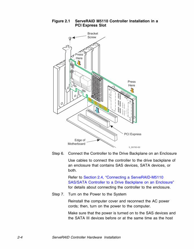
Step 5. Install the Controller
Select a PCI Express slot and align the controller’s PCI Express bus connector to the slot. Press down gently but firmly to ensure that the card is properly seated in the slot. Secure the bracket to the computer chassis.
Figure 2.1 shows the installation of the ServeRAID M5110 controller in a PCI Express slot.
Note: Some PCI Express slots support PCI Express graphics cards only. If a RAID controller is installed one of those slots, the controller does not function.
Attention: To avoid damage to the computer, always remove the controller from the PCI Express slot before you relocate or ship the computer.
2-4 ServeRAID Controller Hardware Installation
Figure 2.1 ServeRAID M5110 Controller Installation in a PCI Express Slot
Step 6. Connect the Controller to the Drive Backplane on an Enclosure
Use cables to connect the controller to the drive backplane of an enclosure that contains SAS devices, SATA devices, or both.
Refer to Section 2.4, “Connecting a ServeRAID-M5110 SAS/SATA Controller to a Drive Backplane on an Enclosure” for details about connecting the controller to the enclosure.
Step 7. Turn on the Power to the System
Reinstall the computer cover and reconnect the AC power cords; then, turn on the power to the computer.
Make sure that the power is turned on to the SAS devices and the SATA III devices before or at the same time as the host
3_00793-00
Edge ofMotherboard
PCI Express
BracketScrew
PressHere
PressHere

Detailed Installation 2-5
computer. If the power is turned on to the computer before it is turned on to the devices, the computer might not recognize the devices.
For the United Extensible Firmware Interface (UEFI), no BIOS message displays. Press F1 to enter System Setup. Refer to your system user’s guide for specific configuration information.
Under other interfaces or operating systems, a BIOS message appears during boot. The firmware takes several seconds to initialize. The configuration utility prompt times out after several seconds. The second portion of the BIOS message displays the controller number, firmware version, and cache SDRAM size. The numbering of the controller follows the PCI slot scanning order used by the host mainboard.
Step 8. Run the WebBIOS Configuration Utility
Run the WebBIOS Configuration Utility to configure the physical arrays and the logical drives. When the message Press <Ctrl><H> for WebBIOS appears on the screen, press CTRL+H immediately to run the utility.
Step 9. Install the Operating System Driver
The controller can operate under various operating systems. To operate under these operating systems, you must install the software drivers. You can find and download the latest drivers at http://www.ibm.com/support/. For updates, click Downloads and drivers.
Device driver updates are made available periodically. To ensure that you have the current version of the driver, download the latest driver at http://www.ibm.com/support/. See the readme file that accompanies the driver for any updated information.
For details on installing the driver, refer to the ServeRAID-M Device Driver Installation User’s Guide on the ServeRAID M Documentation CD. Be sure to use the latest Service Packs provided by the operating system manufacturer and to review the readme file that accompanies the driver.
2-6 ServeRAID Controller Hardware Installation
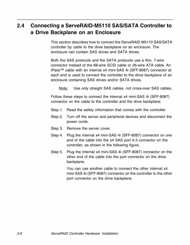
2.4 Connecting a ServeRAID-M5110 SAS/SATA Controller to a Drive Backplane on an Enclosure
This section describes how to connect the ServeRAID M5110 SAS/SATA controller by cable to the drive backplane on an enclosure. The enclosure can contain SAS drives and SATA drives.
Both the SAS protocols and the SATA protocols use a thin, 7-wire connector instead of the 68-wire SCSI cable or 26-wire ATA cable. An iPass™ cable with an internal x4 mini-SAS 4i (SFF-8087) connector at each end is used to connect the controller to the drive backplane of an enclosure containing SAS drives and/or SATA drives.
Note: Use only straight SAS cables, not cross-over SAS cables.
Follow these steps to connect the internal x4 mini-SAS 4i (SFF-8087) connector on the cable to the controller and the drive backplane.
Step 1. Read the safety information that comes with the controller
Step 2. Turn off the server and peripheral devices and disconnect the power cords.
Step 3. Remove the server cover.
Step 4. Plug the internal x4 mini-SAS 4i (SFF-8087) connector on one end of the cable into the x4 SAS port 0-3 connector on the controller, as shown in the following figure.
Step 5. Plug the internal x4 mini-SAS 4i (SFF-8087) connector on the other end of the cable into the port connector on the drive backplane.
You can use another cable to connect the other internal x4 mini-SAS 4i (SFF-8087) connector on the controller to the other port connector on the drive backplane.

After Installing the Controller 2-7
Figure 2.2 Connecting a ServeRAID M5110 Controller Internal Connector to a Drive Backplane
Step 6. Replace the server cover.
Step 7. Slide the server into the rack.
Step 8. Reconnect the power cords and any cables that you removed.
Step 9. Turn on the peripheral devices and the server.
2.5 After Installing the Controller
After the you install the controller, you must configure it and install the operating system driver. The ServeRAID-M Software User’s Guide instructs you on the configuration options and how to set them on your controller. The ServeRAID-M Device Driver Installation User’s Guide provides detailed installation instructions for operating system drivers.
3_01278-00

2-8 ServeRAID Controller Hardware Installation
ServeRAID M5110 SAS/SATA Controller for IBM System x User’s Guide 3-1
Chapter 3ServeRAID M5110 SAS/SATA Controller Characteristics
This chapter describes the characteristics of the ServeRAID M5110 SAS/SATA controller. It consists of the following sections:
Section 3.1, “ServeRAID M5110 SAS/SATA Controller Descriptions”
Section 3.2, “Characteristics of the ServeRAID M5110 SAS/SATA Controller”
Section 3.3, “Technical Specifications”
3.1 ServeRAID M5110 SAS/SATA Controller Descriptions
The ServeRAID M5110 SAS/SATA controller is dual PHY, SAS PCI Express controllers and is used in systems with a PCI Express slot. PCI Express goes beyond the PCI specification in that it is intended as a unifying I/O architecture for various systems: desktops, workstations, mobile, server, communications, and embedded devices.
The ServeRAID M5110 controller has one LSISAS2208 ROC (RAID-on-chip) processor that controls eight internal SAS/SATA ports through two SFF-8087 x4 internal mini SAS connectors.
3.1.1 Board Layout and Connector Information
This subsection provides the board layout and connector information for the controller. The following subsections provide graphics and connector information for the controller.
The controller has eight internal SAS/SATA connectors. The followoing figure displays the connectors on the controller, which are described on Table 3.1.

3-2 ServeRAID M5110 SAS/SATA Controller Characteristics
Figure 3.1 Card Layout for the ServeRAID M5110 SAS/SATA Controller
WILL REPLACE WITH UPDATED GRAPHIC
Table 3.1 ServeRAID M5110 SAS/SATA Controller Connectors
Connector Description Type Comments
J1A1 Global drive fault LED header
2-pin connector
Connects to an LED that indicates whether a drive is in a fault condition.
J1A2 Write pending LED header
2-pin connector
Connects to an LED that indicates when the data in the cache has yet to be written to the storage devices. Used when the write-back feature is enabled.
J1A3 Test header 2-pin connector
Reserved for internal use.
J2B1 J2B2
J1A1J1A2J1A3
J1A4J1A5
J1A7
J2B4
J5B1
J5A1 J6A1
J1B1
J1A8
J1A1
ak
+ve
-ve
J1A2
ak
+ve
-ve

ServeRAID M5110 SAS/SATA Controller Descriptions 3-3
J1A4 Activity LED header 2-pin connector
Connects to an LED that indicates activity on the drives connected to the controller.
J1A5 Individual PHY and Drive Fault Indication headerPorts 3-0Ports 7-4
2x8-pin header
Connects to an LED that indicates whether a drive is in a fault condition. There is one LED per port. When lit, each LED indicates the corresponding drive has failed or is in the Unconfigured-Bad state.The LEDs function in a direct-attach configuration (there are no SAS expanders). Direct attach is defined as a maximum of one drive connected directly to each port.
J1A7 I2C Enclosure Management connector
3-pin connector
Supports SES (SCSI enclosure services) over I2C through an internal I2C backplane cable.
Table 3.1 ServeRAID M5110 SAS/SATA Controller Connectors (Cont.)
Connector Description Type Comments
J1A4+ve
a k
-ve
J1A5
+ve-ve
ak
J1A7
1
2
3

3-4 ServeRAID M5110 SAS/SATA Controller Characteristics
J1A8 I2O Mode Selection 2-pin header
Installing this jumper causes the RAID controller to run in I2O Mode. The default mode of operation is without the shunt.Note: The MegaRAID firmware
does not require this con-nector to be installed in order to function.
J1B1 Serial EEPROM (SBR)
2-pin connector
Provides controller information, such as the serial number, revision, and manufacturing date. The default is no shunt installed.
J2B1 x4 SAS Ports 4-7 internal connector
SFF-8087 mini-SAS 4i internal connector
Connects the controller by cable to SAS drives or SATA III drives.
J2B2 x4 SAS Ports 0-3 internal connector
SFF-8087 mini-SAS 4i internal connector
Connects the controller by cable to SAS drives or SATA III drives.
J2B4 PCI Express® Standard edge card connector
The RAID controller interfaces with the host system through a standard edge card.
This interface provides power to the board and an I2C interface connected to the I2C bus for IPMI.
Table 3.1 ServeRAID M5110 SAS/SATA Controller Connectors (Cont.)
Connector Description Type Comments
Characteristics of the ServeRAID M5110 SAS/SATA Controller 3-5
3.2 Characteristics of the ServeRAID M5110 SAS/SATA
Controller
Table 3.2 shows the general characteristics of the ServeRAID M5110 SAS/SATA controller.
The controller ensures data integrity by intelligently validating the compatibility of the SAS domain. The controller uses Fusion-MPT architecture, which allows for thinner drivers and better performance.
J5A1 Serial Universal Asynchronous Receiver/Transmitter (UART) connector for the Expander
4-pin connector
Reserved for internal use.
J5B1 CVFM03 DDR3 connector
240-pin connector
Connects the controller to the CVFM03 CacheVault Flash Module. The CVFM03 module connects to a remote CVPM02 CacheVault Power Module.
J6A1 Serial Universal Asynchronous Receiver/Transmitter (UART) connector for the Expander
4-pin connector
Reserved for internal use.
Table 3.1 ServeRAID M5110 SAS/SATA Controller Connectors (Cont.)
Connector Description Type Comments
Table 3.2 ServeRAID M5110 SAS/SATA Controller Characteristics
FlashROM1
1. For boot code and firmware.
Serial EEPROM2
2. For BIOS configuration storage.
SAS Data Transfers SCSI FeaturesSCSI Termination
Yes Yes Up to 6 Gb/s per port Plug and PlayScatter/GatherActivity LED
Active
3-6 ServeRAID M5110 SAS/SATA Controller Characteristics
3.3 Technical Specifications
The design and implementation of the ServeRAID M5110 SAS/SATA controller minimize electromagnetic emissions, susceptibility to radio frequency energy, and the effects of electrostatic discharge. The controller carries the following marks and certifications:
CE mark
C-Tick mark
FCC Self-Certification logo
Canadian Compliance Statement
Korean MIC
Taiwan BSMI
Japan VCCI
In addition, the controller meets the requirements of CISPR Class B.
The ServeRAID M5110 SAS/SATA controller is CSA C22.2 No. 60950-1, UL 60950-1 First Edition listed Accessory, UL file number E257743.
3.3.1 Controller Specifications
Table 3.3 lists the specifications for the ServeRAID M5110 SAS/SATA controller.
Table 3.3 ServeRAID M5110 SAS/SATA Controller Specifications
Specification ServeRAID M5110 SAS/SATA Controller
Processor(PCI Express Host Controller to PCI Secondary I/O Controller)
LSISAS2208 ROC device with Integrated PowerPC processor
Operating Voltage +3.3 V, +12 V
Card Size Low profile PCI Express controller card size (2.713" x 6.6")
Array Interface to Host
PCI Express Rev 3.0

Technical Specifications 3-7
3.3.2 Array Performance Features
Table 3.4 shows the array performance features for the ServeRAID M5110 SAS/SATA controller.
Type of Drives Supported
Serial Attached SCSI (SAS) and Serial ATA (SATA)
PCI Express Bus Data Transfer Rate
Up to 8 GT/s (1 GB/s) per lane x8 lane width Up to 2 GB/s per direction for SAS x4 cards
(4 GB/s total)
Serial Port 3-pin RS232-compatible connector (for manufacturing use only)
SAS Controller(s) One LSISAS2208 Single SAS controller
SAS Bus Speed 6 Gb/s
SAS Ports Two SAS connectors with four SAS ports each
Size of Flash ROM for Firmware
8 Mbytes
Nonvolatile Random Access Memory (NVRAM)
32 Kbytes for storing RAID configuration
Table 3.3 ServeRAID M5110 SAS/SATA Controller Specifications (Cont.)
Specification ServeRAID M5110 SAS/SATA Controller
Table 3.4 Array Performance Features
Specification ServeRAID M5110 SAS/SATA Controller
PCI Express Host Data Transfer Rate
8 GT/s (1 GB/s) per lane
Drive Data Transfer Rate 6.0 Gb/s per lane
Maximum Scatter/Gathers 26 elements
Maximum Size of I/O Requests 6.4 Mbytes in 64 Kbyte stripes
Maximum Queue Tags per Drive As many as the drive can accept
Stripe Sizes 8, 16, 32, or 64 Kbyte
Maximum Number of Concurrent Commands
255
3-8 ServeRAID M5110 SAS/SATA Controller Characteristics
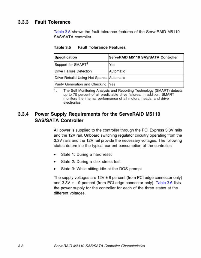
3.3.3 Fault Tolerance
Table 3.5 shows the fault tolerance features of the ServeRAID M5110 SAS/SATA controller.
3.3.4 Power Supply Requirements for the ServeRAID M5110 SAS/SATA Controller
All power is supplied to the controller through the PCI Express 3.3V rails and the 12V rail. Onboard switching regulator circuitry operating from the 3.3V rails and the 12V rail provide the necessary voltages. The following states determine the typical current consumption of the controller:
State 1: During a hard reset
State 2: During a disk stress test
State 3: While sitting idle at the DOS prompt
The supply voltages are 12V ± 8 percent (from PCI edge connector only) and 3.3V ± - 9 percent (from PCI edge connector only). Table 3.6 lists the power supply for the controller for each of the three states at the different voltages.
Table 3.5 Fault Tolerance Features
Specification ServeRAID M5110 SAS/SATA Controller
Support for SMART1
1. The Self Monitoring Analysis and Reporting Technology (SMART) detects up to 70 percent of all predictable drive failures. In addition, SMART monitors the internal performance of all motors, heads, and drive electronics.
Yes
Drive Failure Detection Automatic
Drive Rebuild Using Hot Spares Automatic
Parity Generation and Checking Yes

Technical Specifications 3-9
3.3.5 Operating and Non-operating Conditions
The operating (thermal and atmospheric) conditions for the ServeRAID M5110 SAS/SATA controller are:
Relative humidity range is 20 percent to 80 percent noncondensing
Airflow must be at least 200 linear feet per minute (LFPM) to avoid operating the Intel IOP333 processor above the maximum ambient temperature
Temperature range: +0 C to +60 C
The parameters for the non-operating (such as storage and transit) environment for the controller are:
Relative humidity range is 5 percent to 90 percent noncondensing
Temperature range: 30C to +80 C
3.3.6 Safety Characteristics
The ServeRAID M5110 SAS/SATA controller meets or exceeds the requirements of UL flammability rating 94 V0. Each bare board is also marked with the supplier name or trademark, type, and UL flammability rating. The board is installed in a PCI Express bus slot, so all voltages are lower than the SELV 42.4 V limit.
Table 3.6 Power Supply for the ServeRAID M5110 SAS/SATA Controller
PCI Edge Connector State 1 State 2 State 3
3.3V supply 0.1A 0.94762905A 0.94232971A
+12V supply 0.84A 0.53350067A 0.53209699A
3.3V auxiliary supply 0.76A 0.007135698A 0.0035464705A

3-10 ServeRAID M5110 SAS/SATA Controller Characteristics
ServeRAID M5110 SAS/SATA Controller for IBM System x User’s Guide A-1
Appendix A Getting Help and Technical Assistance
If you need help , service, or technical assistance or just want more information about IBM products, you will find a wide variety of sources available from IBM to assist you. Use this information to obtain additional information about IBM and IBM products, determine what to do if you experience a problem with your IBM system or optional device, and determine whom to call for service, if it is necessary.
A-2 Getting Help and Technical Assistance
A.1 Before you call
Before you call, make sure that you have taken these steps to try to solve the problem yourself:
Check all cables to make sure that they are connected. Check the power switches to make sure that the system and any optional devices
are turned on. Check for updated firmware and operating-system device drivers for your IBM
product. The IBM Warranty terms and conditions state that you, the owner of the IBM product, are responsible for maintaining and updating all software and firmware for the product (unless it is covered by an additional maintenance contract). Your IBM service technician will request that you upgrade your software and firmware if the problem has a documented solution within a software upgrade.
If you have installed new hardware or software in your environment, check http://www.ibm.com/systems/info/x86servers/serverproven/compat/us/ to make sure that the hardware and software is supported by your IBM product.
Go to http://www.ibm.com/supportportal/ to check for information to help you solve the problem.
Gather the following information to provide to IBM Support. This data will help IBM Support quickly provide a solution to your problem and ensure that you receive the level of service for which you might have contracted.
o Hardware and Software Maintenance agreement contract numbers, if applicable
o Machine type number (IBM 4-digit machine identifier) o Model number o Serial number o Current system UEFI and firmware levels o Other pertinent information such as error messages and logs
Go to http://www.ibm.com/support/entry/portal/Open_service_request/ to submit an Electronic Service Request. Submitting an Electronic Service Request will start the process of determining a solution to your problem by making the pertinent information available to IBM Support quickly and efficiently. IBM service technicians can start working on your solution as soon as you have completed and submitted an Electronic Service Request.
You can solve many problems without outside assistance by following the troubleshooting procedures that IBM provides in the online help or in the documentation that is provided with your IBM product. The documentation that comes with IBM systems also describes the diagnostic tests that you can perform. Most systems, operating systems, and programs come with documentation that contains troubleshooting procedures and explanations of error messages and error codes. If you suspect a software problem, see the documentation for the operating system or program.

Using the documentation A-3
A.2 Using the documentation
A.3 Getting help and information from the World Wide Web
A.4 How to send Dynamic System Analysis data to IBM
Information about your IBM system and preinstalled software, if any, or optional device is available in the documentation that comes with the product. That documentation can include printed documents, online documents, readme files, and help files. See the troubleshooting information in your system documentation for instructions for using the diagnostic programs. The troubleshooting information or the diagnostic programs might tell you that you need additional or updated device drivers or other software. IBM maintains pages on the World Wide Web where you can get the latest technical information and download device drivers and updates. To access these pages, go to http://www.ibm.com/supportportal/. Also, some documents are available through the IBM Publications Center at h ttp://www.ibm.com/shop/publications/order/.
On the World Wide Web, up-to-date information about IBM systems, optional devices, services, and support is available at http://www.ibm.com/supportportal/. The address for IBM System x® information is http://www.ibm.com/systems/x/. The address for IBM BladeCenter® information is h ttp://www.ibm.com/systems/bladecenter/. The address for IBM IntelliStation® information is http://www.ibm.com/systems/intellistation/.
Use the IBM Enhanced Customer Data Repository to send diagnostic data to IBM. Before you send diagnostic data to IBM, read the terms of use at http://www.ibm.com/de/support/ecurep/terms.html.
You can use any of the following methods to send diagnostic data to IBM:
Standard upload: http://www.ibm.com/de/support/ecurep/send_http.html Standard upload with the system serial number:
http://www.ecurep.ibm.com/app/upload_hw Secure upload: http://www.ibm.com/de/support/ecurep/send_http.html#secure Secure upload with the system serial number:
https://www.ecurep.ibm.com/app/upload_hw

A-4 Getting Help and Technical Assistance
A.5 Creating a personalized support web page
A.6 Software service and support
A.7 Hardware service and support
At http://www.ibm.com/support/mynotifications/, you can create a personalized support web page by identifying IBM products that are of interest to you. From this personalized page, you can subscribe to weekly email notifications about new technical documents, search for information and downloads, and access various administrative services.
Through IBM Support Line, you can get telephone assistance, for a fee, with usage, configuration, and software problems with your IBM products. For information about which products are supported by Support Line in your country or region, see http://www.ibm.com/services/supline/products/.
For more information about Support Line and other IBM services, see http://www.ibm.com/services/, or see http://www.ibm.com/planetwide/ for support telephone numbers. In the U.S. and Canada, call 1-800-IBM-SERV (1-800-426-7378).
IBM Taiwan product service A-5
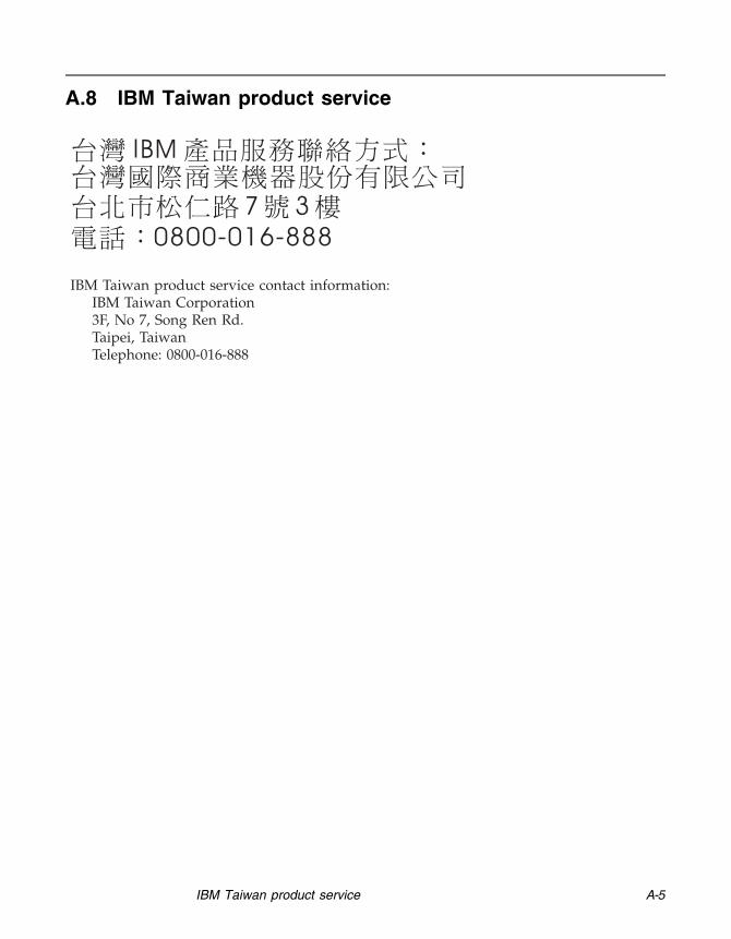
A.8 IBM Taiwan product service

A-6 Getting Help and Technical Assistance

ServeRAID M5110 SAS/SATA Controller for IBM System x User’s Guide B-1
Appendix B Notices
B-2 Notices
B.1 Trademarks
IBM, the IBM logo, and ibm.com are trademarks of InternationalBusiness Machines Corp., registered in many jurisdictions worldwide.Other product and service names might be trademarks of IBM or othercompanies. A current list of IBM trademarks is available on the web at"Copyright and trademark information"at http://www.ibm.com/legal/copytrade.shtml
Adobe and PostScript are either registered trademarks or trademarks ofAdobe Systems Incorporated in the United States and/or other countries.
Cell Broadband Engine is a trademark of Sony Computer Entertainment, Inc., in theUnited States, other countries, or both and is used under licensetherefrom.
Intel, Intel Xeon, Itanium, and Pentium are trademarksor registered trademarks of Intel Corporation or its subsidiariesin the United States and other countries.
Java and all Java-based trademarks and logos are trademarks or registeredtrademarks of Oracle and/or its affiliates.
Linux is a registered trademark of LinusTorvalds in the United States, other countries, or both.
Microsoft, Windows, and Windows NT are trademarks of Microsoft Corporation inthe United States, other countries, or both.
UNIX is a registered trademark of The Open Group in the United States and other countries.

Important Notes B-3
B.2 Important Notes
Processor speed indicates the internal clock speed of the microprocessor; other factors also affect application performance.
CD or DVD drive speed is the variable read rate. Actual speeds vary and are often less than the possible maximum.
When referring to processor storage, real and virtual storage, or channel volume, KB stands for 1024 bytes, MB stands for 1,048,576 bytes, and GB stands for 1,073,741,824 bytes.
When referring to hard disk drive capacity or communications volume, MB stands for 1,000,000 bytes, and GB stands for 1,000,000,000 bytes. Total user-accessible capacity can vary depending on operating environments.
Maximum internal hard disk drive capacities assume the replacement of any standard hard disk drives and population of all hard disk drive bays with the largest currently supported drives that are available from IBM.
Maximum memory might require replacement of the standard memory with an optional memory module.
IBM makes no representation or warranties regarding non-IBM products and services that are ServerProven®, including but not limited to the implied warranties of merchantability and fitness for a particular purpose. These products are offered and warranted solely by third parties.
IBM makes no representations or warranties with respect to non-IBM products. Support (if any) for the non-IBM products is provided by the third party, not IBM.
Some software might differ from its retail version (if available) and might not include user manuals or all program functionality.

B-4 Notices
B.3 Particulate contamination
Attention: Airborne particulates (including metal flakes or particles) and reactive gases acting alone or in combination with other environmental factors such as humidity or temperature might pose a risk to the device that is described in this document. Risks that are posed by the presence of excessive particulate levels or concentrations of harmful gases include damage that might cause the device to malfunction or cease functioning altogether. This specification sets forth limits for particulates and gases that are intended to avoid such damage. The limits must not be viewed or used as definitive limits, because numerous other factors, such as temperature or moisture content of the air, can influence the impact of particulates or environmental corrosives and gaseous contaminant transfer. In the absence of specific limits that are set forth in this document, you must implement practices that maintain particulate and gas levels that are consistent with the protection of human health and safety. If IBM determines that the levels of particulates or gases in your environment have caused damage to the device, IBM may condition provision of repair or replacement of devices or parts on implementation of appropriate remedial measures to mitigate such environmental contamination. Implementation of such remedial measures is a customer responsibility.
Table 5. Limits for particulates and gases
Contaminant Limits
Particulate
The room air must be continuously filtered with 40% atmospheric dust spot efficiency (MERV 9) according to ASHRAE Standard 52.21.
Air that enters a data center must be filtered to 99.97% efficiency or greater, using high-efficiency particulate air (HEPA) filters that meet MIL-STD-282.
The deliquescent relative humidity of the particulate contamination must be more than 60%2.
The room must be free of conductive contamination such as zinc whiskers.
Gaseous Copper: Class G1 as per ANSI/ISA 71.04-19853 Silver: Corrosion rate of less than 300 Å in 30 days
1 ASHRAE 52.2-2008 - Method of Testing General Ventilation Air-Cleaning Devices for Removal Efficiency by Particle Size. Atlanta: American Society of Heating, Refrigerating and Air-Conditioning Engineers, Inc.
2 The deliquescent relative humidity of particulate contamination is the relative humidity at which the dust absorbs enough water to become wet and promote ionic conduction.
3 ANSI/ISA-71.04-1985. Environmental conditions for process measurement and control systems: Airborne contaminants. Instrument Society of America, Research Triangle Park, North Carolina, U.S.A.
Documentation format B-5
B.4 Documentation format
B.5 Telecommunication regulatory statement
B.6 Electronic emission notices
The publications for this product are in Adobe Portable Document Format (PDF) and should be compliant with accessibility standards. If you experience difficulties when you use the PDF files and want to request a web-based format or accessible PDF document for a publication, d irect your mail to the following address:
Information Development IBM Corporation 205/A015 3039 E. Cornwallis Road P.O. Box 12195 Research Triangle Park, North Carolina 27709-2195 U.S.A.
In the request, be sure to include the publication part number and title.
When you send information to IBM, you grant IBM a nonexclusive right to use or distribute the information in any way it believes appropriate without incurring any obligation to you.
This product is not intended to be connected directly or indirectly by any means whatsoever to interfaces of public telecommunications networks, nor is it intended to beused in a public services network.
When you attach a monitor to the equipment, you must use the designated monitor cable and any interference suppression devices that are supplied with the monitor.

B-6 Notices
Electronic emission notices B-7
B-8 Notices

Electronic emission notices B-9
Deutschland: Einhaltung des Gesetzes über die elektromagnetische Verträglichkeit von Geräten
Dieses Produkt entspricht dem "Gesetz über die elektromagnetische Verträglichkeit von Geräten (EMVG)". Dies ist d ie Umsetzung der EU-Richtlinie 2004/108/EG in der Bundesrepublik Deutschland.
Zulassungsbescheinigung laut dem Deutschen Gesetz über die elektromagnetische Verträglichkeit von Geräten (EMVG) (bzw. der EMC EG Richtlinie 2004/108/EG) für Geräte der Klasse A
Dieses Gerät ist berechtigt, in Übereinstimmung mit dem Deutschen EMVG das EG-Konformitätszeichen - CE - zu führen.
Verantwortlich für die Einhaltung der EMV Vorschriften ist der Hersteller:
International Business Machines Corp. New Orchard Road Armonk, New York 10504 914-499-1900
Der verantwortliche Ansprechpartner des Herstellers in der EU ist:
IBM Deutschland Technical Regulations, Department M456 IBM-Allee 1, 71137 Ehningen, Germany Telephone: +49 7032 15-2937 Email: [email protected]
Generelle Informationen:
Das Gerät erfüllt die Schutzanforderungen nach EN 55024 und EN 55022 Klasse A.
VCCI Class A statement

B-10 Notices
This is a Class A product based on the standard of the Voluntary Control Council for Interference (VCCI). If this equipment is used in a domestic environment, radio interference may occur, in which case the user may be required to take corrective actions.
This is electromagnetic wave compatibility equipmentfor business (Type A). Sellers and users need to payattention to it. This is for any areas other than home.
ServeRAID M5110 SAS/SATA Controller User’s Guide C-1
Appendix C Glossary of Terms and Abbreviations
active termination
The electrical connection required at each end of the SCSI bus, composed of active voltage regulation and a set of termination resistors.
array An array of drives combines the storage space on the drives into a single segment of storage space. A hot spare drive does not actively participate in an array.
BIOS Acronym for Basic Input/Output System. Software that provides basic read/write capability. Usually kept as firmware (ROM-based). The system BIOS on the mainboard of a computer boots and controls the system. The BIOS on your host controller acts as an extension of the system BIOS.
configuration Refers to the way a computer is set up, the combined hardware components (computer, monitor, keyboard, and peripheral devices) that make up a computer system, or the software settings that allow the hardware components to communicate with each other.
device driver A program that allows a microprocessor (through the operating system) to direct the operation of a peripheral device.
domain validation
Domain Validation is a software procedure in which a host queries a device to determine its ability to communicate at the negotiated data rate.
EEPROM Acronym for Electronically Erasable Programmable Read-Only Memory. It is a memory chip that typically stores configuration information, as it provides stable storage for long periods without electricity and can be reprogrammed. Refer to NVRAM.
external SAS device
A SAS device installed outside the computer cabinet. These devices are connected using specific types of shielded cables.
Fusion-MPT architecture
Fusion-MPT (Message Passing Technology) architecture consists of several main elements: Fusion-MPT firmware, the Fibre Channel and

C-2 Glossary of Terms and Abbreviations
SCSI hardware, and the operating system level drivers that support these architectures. Fusion-MPT architecture offers a single binary, operating system driver that supports both Fibre Channel and SCSI devices.
host The computer system in which a storage controller is installed. It uses the storage controller to transfer information to and from devices attached to the SCSI bus.
host controller board
A circuit board or integrated circuit that provides a device connection to the computer system.
hot spare An idle, powered on, standby drive ready for immediate use in case of disk failure. It does not contain any user data. A hot spare can be dedicated to a single redundant array or it can be part of the global hot-spare pool for all arrays managed by the controller.
When a disk fails, the controller firmware automatically replaces and rebuilds the data from the failed drive to the hot spare. Data can be rebuilt only from virtual disks with redundancy (RAID levels 1, 5, 6, 10, 50, and 60; not RAID level 0), and the hot spare must have sufficient capacity.
internal SAS device
A SAS device installed inside the computer cabinet. These devices are connected by using a shielded cable.
main memory The part of a computer’s memory which is directly accessible by the CPU (usually synonymous with RAM).
NVRAM Acronym for Nonvolatile Random Access Memory. An EEPROM (Electronically Erasable Read-Only Memory chip) that stores configuration information. Refer to EEPROM.
PCI Acronym for Peripheral Component Interconnect. A high-performance, local bus specification that allows the connection of devices directly to computer memory. The PCI Local Bus allows transparent upgrades from 32-bit data path at 33 MHz to 64-bit data path at 33 MHz, and from 32-bit data path at 66 MHz to 64-bit data path at 66 MHz.
PCI Express Acronym for Peripheral Component Interconnect Express. A high-performance, local bus specification that allows the connection of devices directly to computer memory. PCI Express is a two-way, serial connection that transfers data on two pairs of point-to-point data lines.

C-3
PCI Express goes beyond the PCI specification in that it is intended as a unifying I/O architecture for various systems: desktops, workstations, mobile, server, communications, and embedded devices.
peripheral devices
A piece of hardware (such as a video monitor, drive, printer, or CD-ROM) used with a computer and under the control of the computer. SCSI peripherals are controlled through a ServeRAID SAS/SATA controller (host controller).
PHY The interface required to transmit and receive data packets transferred across the serial bus.
Each PHY can form one side of the physical link in a connection with a PHY on a different SATA device. The physical link contains four wires that form two differential signal pairs. One differential pair transmits signals, while the other differential pair receives signals. Both differential pairs operate simultaneously and allow concurrent data transmission in both the receive and the transmit directions.
RAID Acronym for Redundant Array of Independent Disks (originally Redundant Array of Inexpensive Disks). An array of multiple independent physical disks managed together to yield higher reliability and/or performance exceeding that of a single physical disk. The RAID array appears to the controller as a single storage unit. I/O is expedited because several disks can be accessed simultaneously. Redundant RAID levels (RAID levels 1, 5, 6, 10, 50, and 60) provide data protection.
RAID levels A set of techniques applied to disk groups to deliver higher data availability, and/or performance characteristics to host environments. Each virtual disk must have a RAID level assigned to it.
SAS Acronym for Serial Attached SCSI. A serial, point-to-point, enterprise-level device interface that leverages the proven SCSI protocol set. The SAS interface provides improved performance, simplified cabling, smaller connections, lower pin count, and lower power requirements when compared to parallel SCSI. The SAS controller leverages a common electrical and physical connection interface that is compatible with Serial ATA.
The ServeRAID SAS/SATA controller supports the SAS protocol as described in the Serial Attached SCSI Standard, version 2.0. The controller also supports the Serial ATA III (SATA III) protocol defined by the Serial ATA Revision 3.0. SATA III is an extension to SATA 2.0.

C-4 Glossary of Terms and Abbreviations
The ServeRAID M5110 SAS/SATA controller is a versatile controller that provides the backbone of both server and high-end workstation environments. Each port on the RAID controller supports SAS devices and/or SATA III devices.
SAS device Any device that conforms to the SAS standard and is attached to the SAS bus by a SAS cable. This includes SAS storage controllers (host controllers) and SAS peripherals.
SATA Acronym for Serial Advanced Technology Attachment. A physical storage interface standard, SATA is a serial link that provides point-to-point connections between devices. The thinner serial cables allow for better airflow within the system and permit smaller chassis designs.
SMP Acronym for Serial Management Protocol. SMP enables communicates topology management information directly with an attached SAS expander device. Each PHY on the controller can function as an SMP initiator.
SSD Acronym for Solid State Devices. A Solid State Device uses solid-state memory to store data. They have no moving parts and are faster and more reliable than hard disk drives (HDDs).
SSP Acronym for Serial SCSI Protocol. SSP enables communication with other SAS devices. Each PHY on the SAS controller can function as an SSP initiator or SSP target.
STP Acronym for Serial Tunneling Protocol. STP enables communication with a SATA III device through an attached expander. Each PHY on the SAS controller can function as an STP initiator.
stripe size The total disk space consumed by a stripe not including a parity disk. For example, consider a stripe that contains 64 Kbytes of disk space and has 16 Kbytes of data residing on each disk in the stripe. In this case, the stripe size is 64 Kbytes and the stripe element size is 16 Kbytes. The stripe depth is four (four physical disks in the stripe). You can specify stripe sizes of 8 Kbytes, 16 Kbytes, 32 Kbytes, or 64 Kbytes for each virtual disk. A larger stripe size produces improved read performance, especially if most of the reads are sequential. For mostly random reads, select a smaller stripe size.
striping Disk striping writes data across two or more disks. Each stripe spans two or more disks but consumes only a portion of each disk. Each disk,
C-5
therefore, may have several stripes. The amount of space consumed by a stripe is the same on each disk included in the stripe. The portion of a stripe that resides on a single disk is a stripe element. Striping by itself does not provide data redundancy; striping in combination with parity provides data redundancy.

C-6 Glossary of Terms and Abbreviations


IBM P/N: 81Y1007®