Indian Standard DESIGN, ERECTION AND TESTING ( STRUCTURAL PORTION ) OF CRANES AND HOISTS — CODE OF PRACTICE (Second Revision ) ICS 53.020.20 0 BIS 2006 BUREAU OF INDIAN STANDARDS MANAK BHAVAN, 9 BAHADUR SHAH ZAFAR MARG NEW DELHI 110002 April 2006 Price Group -15

Welcome message from author
This document is posted to help you gain knowledge. Please leave a comment to let me know what you think about it! Share it to your friends and learn new things together.
Transcript
—.-—
Indian Standard
DESIGN, ERECTION AND TESTING ( STRUCTURAL
PORTION ) OF CRANES AND HOISTS —
CODE OF PRACTICE
(Second Revision )
ICS 53.020.20
0 BIS 2006
BUREAU OF INDIAN STANDARDSMANAK BHAVAN, 9 BAHADUR SHAH ZAFAR MARG
NEW DELHI 110002
April 2006 Price Group -15

Cranes, Lifting Chains and Its Related Equipment”Sectional Committee, ME 14
FOREWORD
This Indian Standard ( Second Revision) was adopted by the Bureau of Indian Standards, after the draft finalizedby the Cranes, Lifiing Chains and Its Related Equipment Sectional Committee had been approved by the MechanicalEngineering Division Council.
This standard covers design of structural portion of cranes and hoists and specifies ,permissible stresses andother details of design. In order to ensure economy in design in reliability in operation: To deal with the subjectconventional Iy, cranes have been broadly classified into eight classes depending upon their duty and number ofhours in service per year. The correct classification of a crane is important and should be joint responsibility ofthe producer and the manufacturer.
This standard was first published in 1963. In the first revision the permissible stresses for memberssubjected to fluctuations of stress have been aligned with IS 1024: 1999 ‘Code of practice for use of welding inbridges and structures subject to dynamic loading’, and AWS D 14.1 introducing the number of cycles ofoperation for fatigue calculations. The limits of camber have also been specified, in the current revision.
[n the current revision, the following points are added:
a) The classifications of the cranes are based on operating time and load spectrum and classification fromMlto M8,
b) State of loading is based on the hoist spectrum,
c) The various loads have been explained elaborately and notch effect,
d) The fatigue and notch effect have been dealt elaborately, ,’,
e) The welding joint design, welding procedures and inspection of welding for industrial cranes have beenexplained in detail, and .
t) The design of bolts, quality of bolts, bolts tightening and effective friction surface has been dealt elaborately.
The composition of the Committee responsible for formulation of this standard is given in AnnexC.
This standard is the first in the series of standards relating to cranes and covers the structural design. The otherstandards covering the mechanical and electrical portion are as follows:
1s3177: 1999 Code of practice for overhead traveling cranes and gantry cranes other than steel workcranes ( second revision )
1S4137 :-1985 Code of practice for heavy duty electric overhead traveling cranes including special servicemath ines for use in steel work (first revision )
1S 807:2006
CONTENTS
6
7
8
9
10
11
12
13
14
15
Scope
References
Terminology
Materials
Classification of Cranes
5.1 Class of Operating Time
5.2 Load Spectrum
5,3 State of Stress — Stress Spectrum
State of Loading
6.1 Loads to be Considered
Loads Due to Climatic Effects
Miscellaneous Loads
8.1 Loads Carried by Platforms
8.2 Seismic Load
8.3 Amplification of Load -
8.4 Case of Loading (Combination of Loads)
8.5 Transportation and Erection
Allowable Stress
9.1 Fundamental Allowable Stress
9.2 Structural Members and Welds
9.3 Rivets, Bolts and Pins
9.4 Conventional Number of Cycles and Stress Spectrum
Stability against Overturning
10.1 Special Measures
10.2 Safety against Movement by the Wind
Calculation of Tension Members
Calculation of Compression Members
Calculation of Box Girder Subjected to Bending and Torsional Stresses
13.1 Bending
13.2 Torsion
Calculation of Members Subjected to Bending by Force in the Direction of Axis
Calculation of Welded Joints
15.1 Stresses on Joints under Tension, Compression or Shear Force
15.2 Combined Stresses on Joints under “Bending and Shear Momenti
Page
1
1
2
-4
4
5
5
5
5
5
10
12
12
12
13
13... ,14
14
14
14
14
21
21
21
21
26
%
26
27
27
27
27
27
IS 807:2006
16 Calculation of Local Buckling of Plates
17
18
19
20
21
22
23
24
25
16.1 Compressive Stress or Shear Stress Acts Independently
16.2 Normal Stress and Shear Stress Acts Simultaneously
Designs of Structural Members Subject to Axial Forces
17.1
17.2
17.3
17.4
17.5
17.6
Net Sectional Area of Tension Member
Slenderness Ratio
Limit for Slenderness Ratio
Compressive Members with Variable Height
Combined Compressive Members
Shear Stress Acting on Combined Compressive Members
Detailed Design of Girders Subjected to Bending
18.1 Rivets or Bolts for Joining Girder
18.2 Rivets, Bolts or Welded Directly Subjected to Wheel Load
18.3 Web Joint of Plate Girder Receiving Bend
Welding of Industrial and Mill Cranes
Limiting Deflection
Camber~
Diaphragms and Vertical Stifl%ess
22.1 Diaphragms
Girder and Connection
Bridge Trucks
24.1 Ratio of Crane Span to End Carriage Wheel Base
24.2 Bridge and Gantry Rails
Welded Box Girders
25.1 Girder Proportion
25.2 Height — Thickness Ratio of Web Plate
25.3 Compression Stress
A?WEX A Classification of Joints
A-1 Design of Bolted Joints
A-1. 1 Co-efficient of Friction (p)
A-1.2 Bolts Tightening
A-l.3 Value of the Tensile Stress Area of the Bolts
A-1.4 Quality of Bolts
ANNEX B Weld Joint Design, Welding Procedures and Inspection of Welding forIndustrial and Mill Cranes
Page
28
28
29
29
29
29
36
36
37
38
38
38
40
40
42
42
42
.,, , 42
42
42
42
42
42
42
44
44
44
45
45
45
45
45
45
48
ii
IS 807:2006
B-1 Allowable Stress
B-2 Base Metal
B-3, WeJd Metal
B4 Fatigue
B-5 Weld Joint Design
B-5.1 General Requirements
B-5.2 Groove Welds
B-5.3 Intermittent Groove Welds
B-5.4 FiIlet Welds
B-5.5 Intermittent Fitlet Welds
B-5.6 Staggerad Intermittent Fillet Welds
B-5.7 Plug and Slot Welds
B-6 Weld Joint Categories
B-7 Welding Process
B-7.1 Tolerances for Groove Weld Joint Preparations for Arc Welding
B-8 Control of Distortion and Shrinkage Stresses
B-9 Nominal Number of Loading Cycles
ANNEX C Committee Composition
Page
48
48
48
48
48
48
48
48
48
48
55
55
55
55
66
66
66
69
...m
IS 807:2006
Indian Standard
DESIGN, ERECTION AND TESTING ( STRUCTURALPORTION ) OF CRANES AND HOISTS —
CODE OF PRACTICE
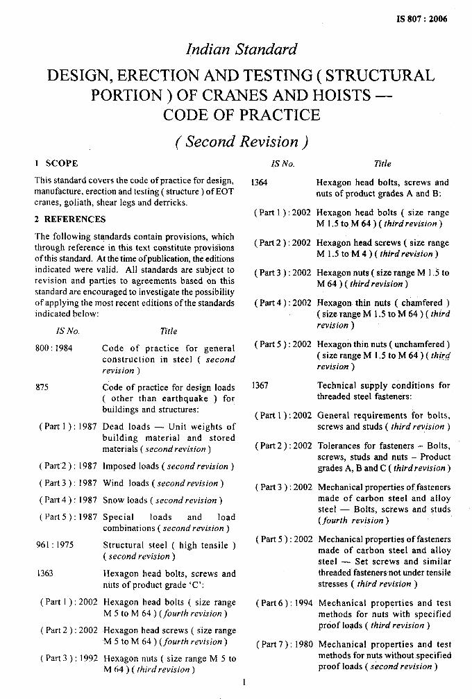
(Second Revision )1 SCOPE
This standard covers the code of practice for design,manufacture, erection and testing ( structure) of EOTcranes, goliath, shear legs and derricks.
2 REFERENCES
The following standards contain provisions, whichthrough reference in this text constitute provisionsof this standard. At the time of publication, the editionsindicated were valid. All standards are subject torevision and parties to agreements based on thisstandard are encouraged to investigate the possibilityof applying the most recent editions of the standardsindicated below:
1S No,
800:1984
875
(Part l): 1987
( Part-2): 1987
(I?art 3): 1987
(Part 4):1987
(Part 5):1987
961:1975
1363
( Part 1 ) :2002
( Part 2 ) :2002
(Part 3):1992
Title
Code of practice for generaIconstruction in steel ( secondrevision )
Code of practice for design loads( other than earthquake ) forbuildings and structures:
Dead loads — Unit weights ofbuilding material and storedmaterials ( second revision )
Imposed loads ( second revision)
Wind loads ( second revision )
Snow loads ( second revision )
Special loads and loadcombinations ( second revision )
Structural steel ( high tensile )( second revision)
Hexagon head bolts, screws andnuts of product grade ‘C’:
Hexagon head “bolts ( size rangeM 5 to M 64 ) (fourth revision)
Hexagon head screws ( size rangeM 5 to M 64) (fourth revision)
Hexagon nuts ( size range M 5 toM 64 ) ( third revision)
IS No.
1364
( Part 1 ): 2002
(Part2 ):2002
(Part 3):2002
( Part 4 ): 2002
( Part 5 ): 2002
1367
(Part 1): 2002
( Part 2 ): 2002
( Part 3 ): 2002
( Part 5 ): 2002
(Part 6): 1994
(Part 7): 1980
Title
Hexagon head bolts, screws andnuts of product grades A and B:
Hexagon head bolts ( size rangeM 1.5 to M 64 ) ( third revision )
Hexagon head screws ( size rangeM 1.5 to-M 4 ) ( third revision )
Hexagon nuts ( size range M 1.5 toM 64 ) ( third revision )
Hexagon thin nuts ( chamfered )( size range M 1.5 to M 64 ) ( third
revision )
Hexagon thin nuts ( unchamfered )( size range M 1.5 to M 64 ) ( third
revision )
Technical supply conditions forthreaded steel fasteners:
General requirements for bolts,screws and studs ( third revision )
Tolerances for fasteners – Bolts,screws, studs and nuts – Productgrades A, B and C ( third revision)
Mechanical properties of.fastenersmade of carbon steel and alloysteel — Bolts, scf.ews and studs(fourth revision )
Mechanical properties of fastenersmade of carbon steel and alloysteel — Set screws and similarthreaded fasteners not under tensilestresses ( third revision )
Mechanical properties and testmethods for nuts with specifiedproof loads ( third revision)
Mechanical properties and testmethods for nuts without specifiedproof loads ( second revision)
1
IS 807:2006
IS No.
( Part 8 ): 2002
( Part 9/See 1 ) :1993
( Part 9/See 2 ) :1993
( Part 10): 2002
(Part 11 ):2002
(Part 12):1981
(Part 13):1983
(Part 14):1984
( Part 14/Sec 1 ) :2002
( Part 14/Sec 2 ) :2002
( Part 14/Sec 3 ) :
2002
( Part
( Part
( Part
( Part
6 ) :2002
7): 1996
8):
9):
996
997
( Part 20 ) :1996
Title
Prevailing torque type steelhexagon nuts — Mechanical andperformance properties ( thirdrevision )
Surface discontinuities, Section 1Bolts, screws and studs for generalapplications ( third revision )
Surface discontinuities, Section 2Bolts, screws and studs for specialapplications ( third revision )
Surface discominuities — Nuts(~hird revision)
Electroplated coatings ( thirdrevision )
Phosphate coatings on threadedfasteners ( second revision )
Hot-dip galvanized coatings onthreaded fasteners (second
revision)
Stainless-steel threaded fasteners( second revision)
Mechanical properties ofcorrosion-resistant stainless steelfasteners, Section 1 Bolts,screws and studs ( third
revision )
Mechanical properties ofcorrosion-resistant stainlesssteel fasteners, Section 2 Nuts( third revision)
Mechanical properties ofcorrosion-resistant stainless steelfasteners, Section 3 Set screwsand sim iIar fasteners not undertensile stress ( third revision )
Designation system for fasteners( third revision)
Inspection, sampling andacceptance procedure ( thirdrevision )
Packaging ( third revision )
Axial load fatigue testing of bolts,screws and studs
Torsional test and minimumtorques for bolts and screws withnominal diameters 1mm to 10mm
IS No
1893:1984
1929:1982
Title
Criteria for earthquake resistantdesign of structures ( fourthrevision )
Specification for hot forged steelrivets for hot closing ( 12to 36 mmdiameter ) (first revision)
2062:1999 Steel for general structuralpurposes — Specification (Jjih
revision )
2155:1982 Specification for cold forged solidsteel rivets for hot closing ( 6 to16 mm diameter ) (first revision)
3138:1966 Specification for hexagonal boltsand nuts ( M42 to M150 )
3737:1966 Leather safety boots for workersin heavy metal industries
6610:1972 Specification for heavy washersfor steel structures
6623:1985 Specification for high strengthstructural nuts (first revision )
6639:1972 Specification for hexagon bolts forsteel structures
6649:1985 Specification for hardenetf’ andtempered washers for highstrength structural bolts and nuts(first revision )
8500:1991 Structural steel ( microalloyed )( medium and high strengthqualities ) —“Specification (,firsfrevision )
3 TERMINOLOGY
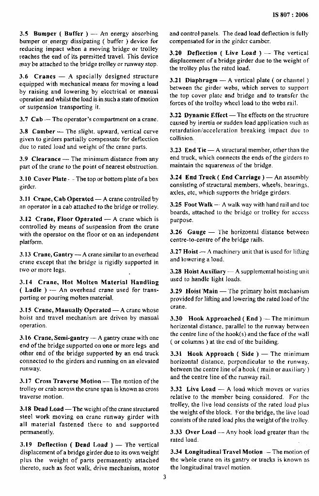
3.1 .Bogie — A short end truck attached to the endof one girder ( or to a connecting member, if more thanone bogie is used per girder). This type of end truckis used when more than four wheels are required ona crane due to the design of the runway.
3.2 Bogie Equalizing — A short end truck whichis flexibly connected to one girder ( or connectingmember ) by means of a pin upon which the truckcan oscillate to equalize thq loading on the two truckwheel.
3.3 Bogie Fixed — A short end truck which is rigidlyconnected to one girder.
3.4 Bridge — That part of a crane consisting ofgirders, trucks, end ties, walk way and drivemechanism which carries the trolleys traveling alongthe runway rails.
2
IS 807:2006
3.5 Bumper ( Buffer ) –- An energy absorbingbumper or energy dissipating ( buffer ) device forreducing impact when a moving bridge or tralleyreaches the end of its permitted travel. This devicemay be attached to the bridge trolley or runway stop.
3.6 Cranes — A specially designed structureequipped with mechanical means for moving a loadby raising and lowering by electrical or manualoperation and whilst the load is in such a state ofmotionor suspension transporting it.
3.7 Cab — The operator’s compartment on a crane.
3.8 Camber — The slight, upward, vertical curvegiven to girders partially compensate for deflectiondue to rated load and weight of the crane parts.
3.9 Clearance — The minimum distance from anypart .of the crane to the point of nearest obstruction.
3.10 Cover Plate — The top or bottom plate of a boxgirder.
3.11 Crane Cab Operated — A crane controlled byan operator in a cab attached to the bridge or trolley.
3.12 Crane, Floor Operated — A crane which iscontrolled by means of suspension from the cranewith the operator on the floor or on an independentplatform.
3.13 Crane, Gantry — A crane similar to an overheadcrane except that the bridge is rigidly supported intwo or more legs.
3.14 Crane, Hot Molten Material Handling( Ladle ) — An overhead crane used for trans-porting or pouring molten material.
3.15 Crane, Manually Operated — A crane whosehoist and travel mechanism are driven by manualoperation.
3.16 Crane, Semi-gantry — A gantry crane with oneend of the bridge supported on one or more legs andother end of the bridge supported by an end truckconnected to the girders and running on an elevatedrunway.
3.17 Cross Traverse Motion — The motion of thetrolley or crab across the crane span is known as crosstraverse motion.
3.-18 Dead Load — The weight of the crane structuredsteel work moving on crane runway girder withall material fastened there to and supportedpermanently.
3.19 Deflection ( Dead Load ) — The verticaldisplacement of a bridge girder due to its own-weightplus the weight of parts permanently attachedthereto, such as foot walk, drive mechanism, motor
and control panels. The dead load deflection is fullycompensated for in the girder camber.
3.20 Deflection ( Live Load ) — The verticaldisplacement of a bridge girder due to the weight ofthe trolley plus the rated load.
3.21 Diaphragm — A vertical plate ( or channel )between the girder webs, which serves to supportthe top cover plate and bridge and to transfer theforces of the trolley wheel load to the webs rail.
3.22 Dynamic Effect — The effects on the structurecaused by inertia or sudden load application such asretardation/acceleration breaking impact due tocollision.
3.23 End Tie — A structural member, other than theend truck, which connects the ends of the girders tomaintain the squareness of the bridge.
3.24 End Truck ( End Carriage) — An assemblyconsisting of structural members, wheels, bearings,axles, etc, which supports the bridge girders.
3.25 Foot Walk — A walk way with hand rail and toeboards, attached to the bridge or trolley for accesspurpose.
3.26 Gauge — The horizontal distance betweencentre-to-centre of the bridge rails.
3.27 Hoist — A machinery unit that is used for Iiftiugand lowering a load.
3.28 Hoist Auxiliary — A supplemental hoisting unit
used to handle light loads.
3.29 Hoist ‘Main — The primary hoist mechanismprovided for lifting and lowering the rated load of thecrane.
3.30 Hook Approached ( End ) — The minimumhorizontal distance, paral Iel to the runway betweenthe centre line of the hook(s) and theface of the wall(-or columns ) at the end of the building.
3.31 Hook Approach ( Side ) — The minimumhorizontal distance, perpendicular to the runway,between the centre line of a hook ( main or auxiliary )and the centre line of the runway rail.
3.32 Live Load — A load which moves or variesrelative to the member being considered. For thetrolley, the live load consists of the rated load plus
the weight of the block. For the bridge, the live loadconsists of the rated load plus the weight of the trolley,
3.33 Over Load — Any hook load greater than therated load.
3.34 Longitudinal Travel Motion — The motion ofthe whole crane on its gantry or tracks is known asthe longitudinal travel motion.
1
IS 807:2006
3.35 Rated Lifted Loads — The rated lifted loadfrom the mechanism design consideration shallmean the external load lifted and handled by the craneand shall include in addition the safe working load,lifting tackles such as magnets, grabs, lifting beams,but shall exclude wind load.
3.36 Radius — The horizontal distance from thecentre line of the lifting hook before loading to thecentre about which the jib slews.
3.37 Reach — The horizontal distance from the centre
line of the laden hook to the nearest point of the chassis/under frame with respect to hook.
3.38 Runway — The assembly of rails, girders, bracketsand frame work on which the crane operates.
3.39 Rail Sweep — A mechanical device attachedto the end truck of a bridge or trolley.
3.40 Span — The horizontal distance between centre-to-centre of the runway rails.
3.41 Stability Base — The effective span of thesupporting base.
3.42 Stability Reach — The distance of the jib headpin from the point of intersection of the nearest baseline and vertical plane passing through the center lineof the jib.
3.43 Stop — A member to physically limit the travelof the trolley orbridge. This member is rigidly attachedto a fixed structure and normally does not have energyabsorbing ability.
3.44 Web Plate — The critical plates, connecting theupper and lower flanges or cover plate of a girder.
3.45 Wheel Base — The distance from centre-to-centre of the outer most wheels of the bridge or trolley,measured parallel to the rail.
3.46 Wind Load — The forces produced by thevelocity of the wind which is assumed to acthorizontally.
3.47 Wheel Load Bridge — The vertical force( without impact) produced on any bridge wheel bythe sum of the rated load, trolley weight and bridgeweight, with the trolley so positioned on the bridgeas to give maximum loading.
3.48 Wheel Load Trolley — The vertical force( without impact) produced on any trolley wheel bythe sum of the rated load and trolley weight.
4 MATERIALS
4.1 The mat~rial of structures shall be in the form ofplate, sheet and rolled sections.
4.2 Structural steel shall conform to IS 2062 or IS 8500as per designers suitability or as mutually agreed tobetween the purchaser and the manufacturerpermissible stress shall be related to yield stress ofthe material used.
4.3 Materials for pins, rivets and bolts including highstrength bolts and nuts shall be as given in Table 1.
4.4 Material characteristics shown in Table 2 may beused for design purpose.
4.5 Table 1 contains the different material grade forprincipal load bearing members and also rivets, pinsand bolts, high strength bolts and nuts. The physicalcharacteristics of steel are given in Table 2.
NOTE— Noblack bolts shall be used forthe principalload bearing members in the crane.
Table 1 Rivet and Bolts
( Clauses 4.3 and4,5 )
S1 No. Product Ref to FndianStandard
(1) (2) (3)
i) Rivets 21551929
ii) Pins and bolts 1364 ( Parts 1 to 5 )3138
iii) High strength bolts and 6639 .,,,nuts 6623
66493757
Table 2 “Physical Properties of Steel
( Clauses 4.4 and4.5 )
S1 No. Parameter Values
(1) (2) (3)
i) Modulus of longitudinal 2. IXI05elasticity ( E ), in N/mm2
ii) Modulus of elasticity in 8.1 x10⁴shear (G), in N/mmz
iii) Poisson’s ratio (I/m) 0.3
iv) Co-efficient of linear 1.2X 10-fexpansion (a)
v) Specific gravity (y) 7.85
5 CLASSIFICATION OF CRANES
There are two factors to be taken into considerationfor Ihe purpose of determining the group to whichthe cranes belong are the class of utilization and thestate of loading, that is:
a) Class of operating time; and
b) Load spectrum.
4
5.1 Class of Ope&ing Time
a) Class of operating time indicates the averageperiod per day;
b) Two hundred fitly working days per year shallbe considered; and
c) Higher classes of operating time for more thanone shift per day.
5.1.1 Class of utilization takes account of the
frequency of one of the cranes as a whole when inservice. This concept could be represented by thenumber of working cycles, which the crane wouldaccomplish during its life ( see Table 3 ). The classesof utilization are used as a basis for the design of thestructure.
5.2 Load Spectrum
5.2.1 State of Hoist Loading — Hoist Load
Spectrum
The state of hoist loading determines the extentto which the crane lifts the maximum load, L~a or onlya lesser load, L, This idea is illustrated by a spectrumof hoist loads showing the number of cycles ofoperation during which a certain fraction of themaximum load is reached or exceeded. It is one of theimportant factors determining the severity of theduty of the cranes.
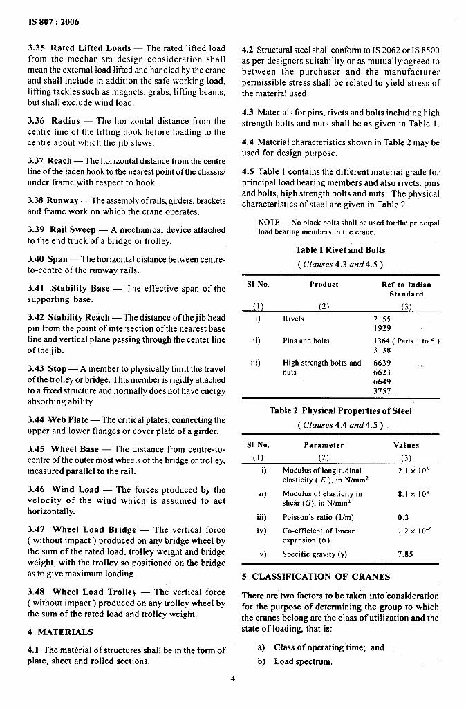
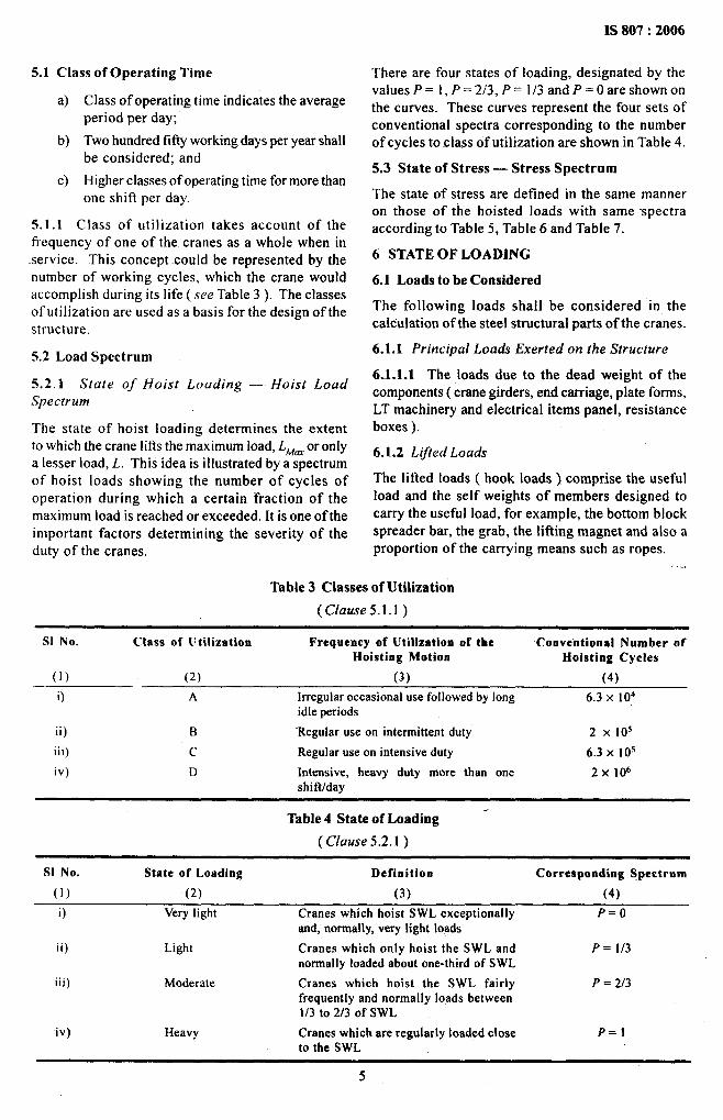
IS 807:2006
There are four states of loading, designated by thevahres P= 1, P=213, P= 1/3 and P= Oare shownonthe curves. These curves represent the four sets ofconventional spectra corresponding to the numberof cycles to class of utilization are shown in Table 4.
5.3 State of Stress — Stress Spectrum
The state of stress are defined in the same manneron those of the hoisted loads with same -spectraaccording to Table 5, Table 6 and Table 7.
6 STATE OF LOADING
6.1 Loads to be Considered
The following loads shall be considered in thecalculation of the steel structural parts of the cranes.
6.1.1 Principal Loads Exerted on the Structure
6J.I.1 The loads due to the dead weight of thecomponents ( crane girders, end carriage, plate forms,LT machinery and electrical items panel, resistanceboxes ).
6.1.2 Lifted Loads
The lifted loads ( hook loads ) comprise the usefulload and the self weights of members designed tocarry the useful load, for example, the bottom blockspreader bar, the grab, the lifting magnet and also aproportion of the carrying means such as ropes.
.,. ,
Table 3 Classes of Utilization
(Clause 5.1.l )
S1 No. Class of Utilization Frequency of Utilization of the Conventional Number ofHoisting Motion Hoisting Cycles
(.I ) (2) (3) (4)
0 A Irregularoccasionaluse followed by long 6.3 X 10⁴idleperiods
ii) B ‘Regular use on intermittent duty 2 x 10⁵
iii) c Regular use on intensive duty 6.3 X 10s
iv) D Intensive, heavy duty more than one 2x 10⁶shiftlday
Table 4 State of Loading “
( Clause 5.2.1)
S1 No. State of Loading Definition Corresponding Spectrum
(1) (2) (3) (4)
O Very light Cranes which hoist SWL exceptionally P=oand, normally, very Iight loads
ii) Light Cranes which only hoist the SWL and P= 1/3normally loaded about one-third of SWL
iii) Moderate Cranes which hoist the SWL fairly P = 2/3frequently and normally loads between1/3 to 213 of SWL
iv) Heavy Cranes which are regularly loaded close P=lto the SWL
5
IS 807:2006
LIL max. L/L max.
1.0
0.8
0.6
0.4
‘0.2
o
1 10 102 103 104
FIG. 1 GRAPHICAL REPRESENTATIONOF CLASS OF
UTILIZATIONA 6.3 x 10⁴CYCLES
L/L max.
1.0
P=’
0.8
0.6
0.4\
0.2F&
o
1 10 102 103 104 105
FIG. 3 GRAPHICALREPRESENTATIONOF CLASSOFUTILIZATIONC 6.3 x 10⁵CYCLES
1.0
0.8
0.6
0.4
0.2
0
1 10 102 103 104 1(-)5
FIG. 2 GRAPHICALREPRESENTATIONOF CLASS OF
UTILIZATIONB 2 x 10⁵CYCLES
L/L max.
1.0
0.8
0.6
0.4
0.2
0
1 10 102 103 104 105 106
FIG. 4 GRAPHICALREPRESENTATIONOFCLASS OF
UTILIZATIOND 2 x 10⁶CYCLES
Table5 States of Stress
( Clause 5.3)
S1 No. State of Loading Definition Spectrum
(1) (2) (3) (4)
i) Very Iight Components subjected exceptionally to its P=omaximumstress and normally to light
ii) Light Components rarely subjected to its maximum P = 113stress but noskslly about 1/3 of maximum stress
iii) Moderate Components frequently . subjected to its P = 2/3maximumstressand normally stress vary from1/3 to 2/3 of the maximumstress
iv) Heavy Components regularly subjected to its P=lmaximumstress
6

._ _..——-.,!_ —_________ __
IS 807:2006
Table 6 Group Classification of Cranes
“
( Clause 5.3)
S1 No. State of Hoist Loading Class Utilization and Number of Hoisting Cyclesor State of Stress
r A .A B
,c D
6.3 X 10⁴ 2x Iof 6.3 X 10s 2 x I ()(’(1) (2) (3) (4) (5)
i) Very light, P = O(6)
Ml M2, M3 M4ii)
M5Light, P = i/s M2 M3, M4 M5
iii)M6
Moderate, P = 2/3 M3 M4, M5 M6, M7iv)
M8Heavy, P = I M4 M5 M6, M7 M8
Table 7 Examples of Classification of Cranes
S1 No
(1)
O
ii)
iii)
iv)
v)
( Clause 5.3)
Type of Cranes Applications Class of State of GroupUtilization Loading
(2) (3) (4)Over head travei]ing
(5) (6)1. Hot cranes, cranes for power A o-1 MI-M2cranes station, cranes for repair shops
2. Cranes for warehouse, A I -2 M2-M3-M4stocking yard, machine andassembly shop and cranes forgeneral use
3. Store room cranes, workshop B-C 1-2 M4-M5-M6cranes
4. Grabbing over head traveling C-D 3 M6.M7-M8 “’’”cranes, magnetcranes
5. Cranes for steel works C-D 3 M6-M7-M86. Ladle cranes C-D 3 M7-M87. Stripper cranes, soaking pit D 3 M7-M8cranes
8. Charging cranes C-D’ 3 M7-M89. Forging cranes D 3 M7-M8
Gantry cranes 1. Cranes for power station A o-1 M1-M2and cranes for repair shop
2. Cranes for stocking yard B-C 1-2Gantry cranes
M3-M41. Cranes for-container handling B-C 2 M4-M5-M62. Cranes with grab, magnets B-C-D 3 M7-M8
Jib cranes 1. Stocking yard cranes, repair A-B 1-2 MI-M3shop, assembling shop
2. Wharf cranes B-C 2-3 M3-M4-M53. Grabbing and magnet cranes C-D 2-3 M5-Mti-M74. Unloaders D 3 M7-M85. Cranes for building construction B 1-2 M1-M3
Derrick 1. Derrick for heavy load A-B 0-1 MI-M22. Derrick for construction and B 2-3 M3-M4
-building
3. Floating cargo crane A-B 2 M5-M64. Floating grabbing crane A-B 3 M5-M6-M7
7
IS 807:2006
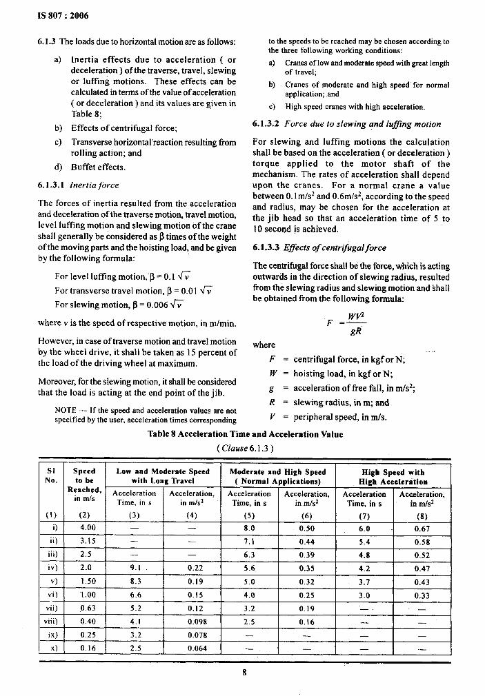
6.1.3 The loads due to horizontal motion areas follows:
a)
b)
c)
d)
6.1.3.1
Inertia effects due to acceleration ( .ordeceleration ) of the traverse, travel, slewingor luffing motions. These effects can becalculated in terms of the value of acceleration(or deceleration ) and its values are given inTable 8;
Effects of centrifugal force;
Transverse horizontal reaction resulting fromrolling action; and
Buffet effects.
fnertia force
The forces of inertia resulted from the accelerationand deceleration of the traverse motion, travel motion,level luffing motion and slewing motion of the craneshall generally be considered as ~ times of the weightof the moving parts and the hoisting load, and be givenby the following formula:
For level luffhg motion, ~ = 0.1 h
For transverse travel motion, ~ = 0.01 W
For slewing motion, ~ = 0.006 W
where v is the speed of respective motion, in m/min.
However, in case of traverse motion and travel motionby the wheel drive, it shall be taken as 15 percent ofthe load of the driving wheel at maximum.
Moreover, for the slewing motion, it shall be consideredthat the load is acting at the end point of the jib.
NOTE— If the speed and acceleration values are notspecified by the user, acceleration times corresponding
to the speeds to be reached maybe chosen according tothe three following working conditions:
a)
b)
c)
6.1.3.2
Cranes of low and moderate speed with great lengthof travel;
Cranes of moderate and high speed for normalapplication; and
High speed cranes with high acceleration.
Force due to slewing and luffing motion
For slewing and luffing motions the calculationshall be based on the acceleration ( or deceleration )torque applied to the motor shaft of themechanism. The rates of acceleration shall dependupon the cranes. For a normal crane a valuebetween 0.1 m/s2 and 0.6m/s2, according to the speedand radius, may be chosen for the acceleration atthe jib head so that an acceleration time of 5 to10 second @achieved.
6.1.3.3 Effects of centrlfixgalforce
The centrifugal force shall be the force, wldch is actingoutwards in the direction of slewing radius, resultedtlom the slewing radius and slewing motion and shallbe obtained from the following formula:
F =&gR
where .,. ,F = centrifugal force, in kgf or N;
W = hoisting load, in kgf or N;
g = acceleration of free fall, in rn/s2;
R = slewirtg radius, in m; and
V = peripheral speed, in mls.
Table 8 Acceleration Time and Acceleration Value
( Clause 6.1.3 )
SI Speed Low and Moderate Speed Moderate and High Speed High Speed withNo. to be with Long Travel ( Normal Applications) High Acceleration
Reached, Acceleration Acceleration, Acceleration Acceleration, Accelerationin m/s
Acceleration,Time, in s in mls2 Time, ins in m/s2 Time, in s
(1)
in m/s2
(2) (3) (4) (5) (6) (7) (8)
i) 4.00 — — 8.0 0.50 6.0 -0.67
ii) 3.15 — — 7.1 0.44 5.4 0.58
iii) 2.5 — — 6.3 0.39 4.8 0.52
iv) 2.0 9.1 0.22 5.6 0.35 4.2 0.47
v) 1.50 8.3 0.19 5.0 0.32 3.7 0.43
vi) “1.00 6.6 0.15 4.0 0.25 3.0 “0.33
vii) 0.63 5.2 0.12 3.2 0.19 —. —
viii) 0.40 4.1 0.098 2.5 0.16 — —
ix) 0.25 3.2 0.078 — — — —
x) 0.16 2.5 0.064 — — — —
8
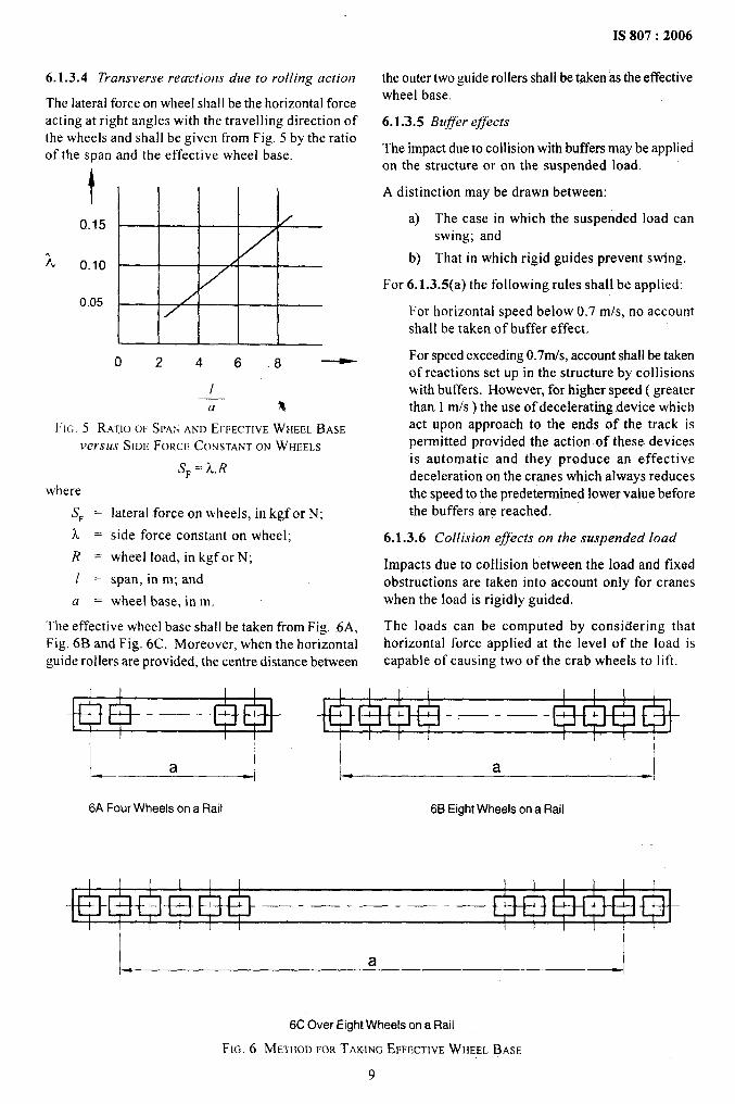
6.1.3.4 Transverse reactions due to rolling action
The lateral force on wheel shal Ibe the horizontal forceacting at right angles with the traveling direction ofthe wheels and shall be given from Fig. 5 by the ratioof the span and the effective wheel base.
t
0.15
0.10
0.05
02468 ~
Ia %
Fi~. 5 RATIOOF SPA:, AND EFFECTIVEWIIEEL BASE
versus SIDE FORCE CONSTANTON WHEELS
where
s, =
L=//.
1=
a=
SF=X,R
lateral force on wheels, in kgf or N;
side force constant on wheel;
wheel load, in kgf or N;
span, in m; and
wheel base, in m.
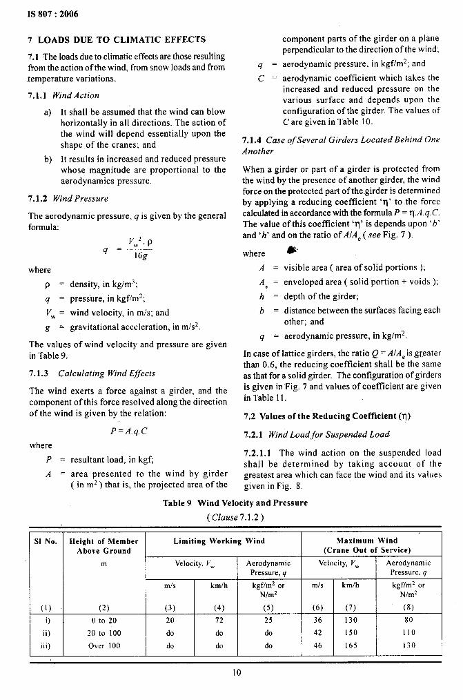
The effective wheel base shall be taken from Fig. .6A,Fig. 6B and Fig. 6C. Moreover, when the horizontalguide rollers are provided, the centre distance between
1S807 :2006
the outer two guide rollers shall be tpken as the effectivewheel base.
6.-I.3.5 Buffer effects
The impact due to collision with buffers may b.eappliedon the structure or on the suspended load.
A distinction maybe drawn between:
a) The case in which the suspended load canswing; and
b) That in which rigid guides prevent swing.
For 6.1.3.5(a) the following rules shall be applied:
For horizontal speed below 0.7 m/s, no accountshall be taken of buffer effect,
For speed exceeding 0.7m/s, account shall be takenof reactions set up in the structure by collisionswith buffers. However, for higher speed ( greaterthan 1 m/s) the use of decelerating device whichact upon approach to the ends of the track ispermitted provided the action of these devicesis automatic and they produce an effectivedeceleration on the cranes which always reducesthe speed to the predetermined lower value beforethe buffers are reached.
6.1.3.6 Collision effects on the suspended load
Impacts due to collision between the load and fix.adobstructions are taken into account only for craneswhen the load is rigidly guided.
The loads can be computed by considering thathorizontal force applied at the level of the load iscapable of causing two of the crab wheels to lift.
I I I I I I
.— — .— —— -
I I I I I
a a
6AFour Wheels on a Rail 66 Eight Wheels on a Rail
I I I I I I I I 1 I
—- —- —— —— —
I
a
6C Over Eight Wheels on a Rail
FIG.6 METHOD FOR TAKING EFFECTIVE WHEEL BASE
9
IS 807:2006
7 LOADS DUE TO CLIMATIC EFFECTS
7.1 The loads due to climatic effects are those resultingfrom the action of the wind, from snow loads and fromtemperature variations.
7.1.1 Wind Action
a)
b)
It shall be assumed that the wind can blowhorizontally in all directions. The action ofthe wind will depend essentially upon theshape of the cranes; and
It res-ults in increased and reduced pressurewhose magnitude are proportional to theaerodynamics pressure.
7.1.2 Wind Pressure
The aerodynamic pressure, q is given by the generalformula:
where
P .
9=Vw=
g.
VW2. p9=— 16g
density, in kglm~;
pressure, in kgffmz;
wind velocity, in m/s; and
gravitational acceleration, in m/s2.
The values of wind velocity and pressure are givenin Table 9.
7.1.3 Calculating Wind Effects
The wind exerts a force against a girder, and thecomponent of this force resolved along the directionof the wind is given by the relation:
wherep.
A=
P= A.q. C
resultant load, in kgfi
area presented to the wind by girder
9=(J.
component parts of the girder on a planeperpendicular to the direction of the wind;
aerodynamic pressure, in kgf/m2; and
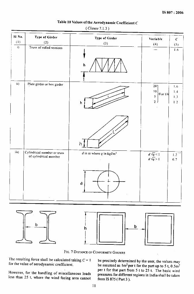
aerodynamic coefficient which takes theincreased and reduced pressure on thevarious surface and depends upon theconfiguration of the girder. The values ofC are given in Table 10.
7.1.4 Case of Several Girders Located Behind One
Another
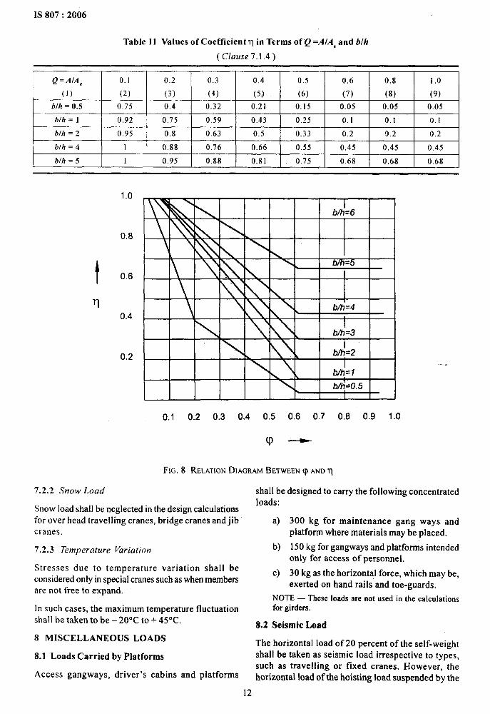
When a girder or part of a girder is protected fromthe wind by the presence of another girder, the windforce on the protected part of the girder is determinedby applying a reducing coefficient ‘q’ to the forcecalculated in accordance with the formula P = ‘rl.A.q. C.The value of this coefficient ‘q’ is depends upon ‘b’
and ‘h’ and on the ratio of A/Ae ( see Fig. 7 ).
where
A=
A, =
h=
b=
&
visible area ( area of solid portions );
enveloped area ( solid portion + voids );
depth of the girder;
distance between the surfaces facing each
9 .other; and
aerodynamic pressure, in kg/m”2.
In case of lattice girders, the ratio Q= A/Aeis.awterthan 0.6, the reducing coefficient shall be the sameas that for a solid girder. The configuration of girdersis given in Fig. 7 and values of coefficient are givenin Table 11.
7,2 Values of the Reducing Coefficient (q)
7.2.1 Wind Load for Suspended Load
7.2.1.1 The wind action on the suspended loadshall be determined by taking account of thegreatest area which can face the wind and its values
( in m-2)that is, the projected area of the given in Fig. 8.
Table 9 Wind Velocity and Pressure
( Clause 7.1.2)
I , 1 IS1 No. Height of Member
Above Ground
m
&ii) 20 to 100
iii) Over 100
Limiting Working Wind I Maximum Wind(Crane Out of Service) I
Velocity, Vw Aerodynamic Velocity, Vw AerodynamicPressure, q Pressure, q
mls kmlh kgf/m2 or mls kmth kgf/m2 orN/m* N/m2
(3) (4) (5) (6) (7) (8)
20 72 25 36 130 80
doldoldo 14211501 110
do I do I do I 46 I 165 I 130
10
.. ——.. ..
1S 807:2006
Table 10 Values of the Aerodynamic Coefficient C
lrl”... n~ 1 9 \
.
\ GLUUJC /.l..J J
S1No. Type of Girder Type of Girder Variable(1)
c(2) (3) (4) (5)
i) Truss of rolled sections
i
— 1.6
h
ii) Plate girder or box girder
@
L
h~
iii) c ylindrical member or truss d in m where q in kgf/m2of cylindrical member
d~<l 1.2’”’
d~>l 0,7
I
d
t
11bFIG. 7 DISTANCEOF CONFORMITYGIRDERS
The resulting force shall be calculated taking C = 1 be-precisely determined by the user, the values mayfor the value of aerodynamic coefficient. be assumed as lm2per t for the part up to 5 t. 0.5m2
per t for that part from 5 t to 25 t. The basic windHo-wever, for the handling of miscellaneous loads
pressures for different regions in India shall be takenless than 25 t, where the wind facing area cannot
fkom1S875 ( Part 3 ).
11
IS 807:2006
Table 11 Values of Coefficient q in Terms of Q =A/A, and b/h
( Clause 7.1.4)
Q=A/Ae 0.1 0.2 0.3 0.4 0.5 0.6 0.8 1,0
(1) (2) (3) (4) (5) (6) (7) (8) (9)
b/h = 0.5 0,75 0.4 0.32 0.21 0.15 0.05 0.05 0.05
blh = 1 0.92 0.75 0.59 0.43 0.25 0.1 0.1 0.1
blh = 2 0.95 0.8 0.63 0.5 0.33 0.2 !).2 0.2
blh = 4 1 0.88 0.76 0.66 0.55 0.45 0.45 0.45
b/h = 5 1 0.95 0.88 0.81 0.75 0.68 0.68 0.68
t
T-1
1.0
0.8
0.6
0.4
0.2
BEsr\\mL \
hI
b/h=6\
b .L\ \ \
\ 1 \ \ \
1k b/h=3
\
b/i=2\ \I
\ \ blh=l
b/h=O. 5[
0.1 0.2 0.3 0.4 0.5 0.6 0.7 0.8 0.9 1.0
FIG. 8 RELATIONDIAGRAM BETWEEN q ANDq
7.2.2 Snow Load
Snow load shall be neglected in the design calculationsfor over head traveling cranes, bridge cranes and jibcranes.
7.2.3 Temperature Variation
Stresses due to temperature variation shall beconsidered only in special cranes such as when membersare not free to expand.
In such cases, the maximum temperature fluctuationshall be taken to be – 20”C to + 45°C.
8 MISCELLANEOUS LOADS
8.1 Loads Carried by Platforms
Access gangways, driver’s cabins and platforms
,,, ,
shall be designed to carry the following concentratedloads:
a)
b)
c)
300 kg for maintenance gang ways andplatform where materials may be placed.
150 kg for gangways and platforms intendedonly for access of personnel.
30 kg as the horizontal force, which may be,exerted on hand rails and toe-guards.
NOTE— These loads are not used in the calculationsfor girders.
8.2 Seismic Load
The horizontal load of 20 percent of the self-weightshall be taken as seismic load irrespective to types,such as traveling or fixed cranes. However, thehorizontal load of the hoisting load suspended by the
12
rope may be neglected.
The seismic load coefficient in some important townin India and map of India showing seismic load aregiven in IS 1893.
8.3 Amplification of-Load
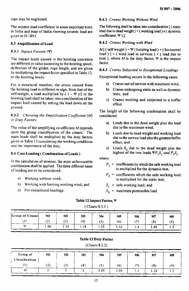
8.3.1 Impact .Factors (Y)
The impact Ioads caused in the hoisting operationare different in value according to the hoisting speed,deflection of the girder, rope length, and are givenby multiplying the impact factor specified in Table 12,to the hoisting loads.
For a structural member, the stress caused fromthe hoisting load is different in sign, from that of theself-weight, a load multiplied by ( 1 – V )/2 to thehoisting load shall be taken into consideration of theimpact load caused by setting the load down on theground.
8.3.2 Choosing the Ampljjication Coefficient (M)
or Duty Factors
The value of the ampli~ing co-efficient M dependsupon the group classification of the cranes. Themain loads shall be multiplied by the duty factorsgiven in Table 13 considering the working conditionsand the importance of the duty.
8.4 Case Loading ( Combination of Loads )
In the calculation of stresses, the most unfavorablecombination shall be applied. The three different casesof loading are to be considered:
a) Working without wind;
b) Working with limiting working wind; and
c) For exceptional loadings,
IS 807:2006
8.4.1 Cranes Working Without Wind
The following shall be taken into consideration [ ( staticload due to deadweight)+ ( working load) x ( dynamiccoefficient, W )].
8.4.2 Cranes Working with Wind
M [ ( self weight ) + Y ( hoisting load ) + ( horizontalload ) ] + ( wind load in services ) + ( load due toheat ), where M is the duty factor, Y is -the impactfactor.
8.4.3 Cranes Sutjected to Exceptional Loadings
Exceptional loading occurs in the following cases:
a)
b)
c)
Cranes out-of-service with maximum wind,
Cranes undergoing static as well as dynamictests, and
Cranes working and subjected to a buffer,effect.
The height of the following combination shall beconsidered:
a)
b)
c)
where
P,
P*
SL
Loads due to the dead weight plus the loaddue to the maximum wind;
Loads due to dead weight and working loaddue to the service load plus the greatest buffereffect; and
Loads S~ due to the dead weight plus thehighest of the-two loads YP,S~ and P&.
= coefficients by which the safe working loadis multiplied for the dynamic test;
= coefficients which the safe working loadis multiplied for the static test;
= safe working load; and
S~ = maximum permissible load,
Table 12 Impact Factor, W
( Clause-8.3.1)
Group of Cranes Ml M2 M3 M4 MS M6 M7 M8
(1) (2) (3) (4) (5) (6) (7) (8) (9)
Y 1.06 1.12 1.18 1.25 1.32 1.4 1.40 1.5
Table 13 Duty Factor
(Clause 8.3.2)
Group of Ml M2 M3 M4 MS M6 M7 M8
Classification
(1) (2) (3) (4) (5) (6) (7) (8) (9)
M 1 1 1 1.05 1.06 1,1 1.12 1.2
IS 807:2006
NOTES
1 Alltheloads aretobe selected intbemostunfavourableposition and magnitude for the member underconsideration. For instance, if the value not multipliedby Y is larger than multiplied by W, the value of Y shouldbe taken as 1.
2 The horizontal loads shall be considered over the worstcombination of loads which may happen simtdtaneouslyof the loads. However if itis clear that the horizontalmotionsdo not occur at the same time with the hoistingmotions, the value of Y may be taken as 1.
3 When the crane is out of service, the trolley shall beplaced at a determined position with no load.
4 in case of the slewing crane, the jib shall be placedat a designated position with no load when out of service.
5 The application of load due to temperature and seismicload shall be referred to 7.2.3 and 8.2,
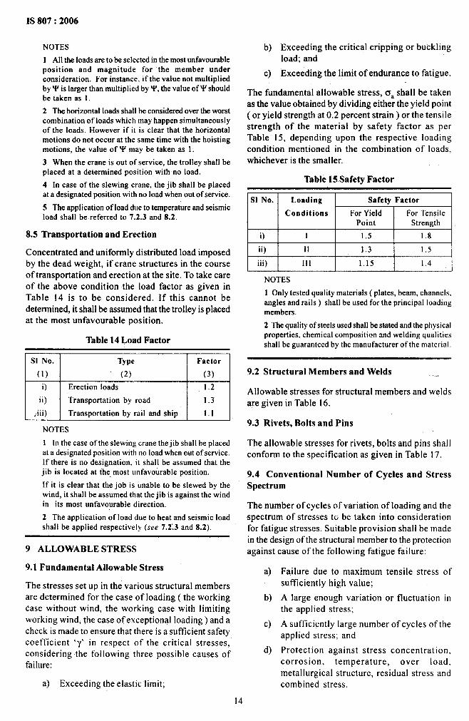
8.5 Transportation and Erection
Concentrated and uniformly distributed load imposedby the dead weight, if crane structures in the courseof transportat ion and erection at the site. To take careof the above condition the load factor as given inTable 14 is to be considered. If this cannot bedetermined, it shall be assumed that the trolley is placedat the most unfavorable position.
Table 14 Load Factor
,I S1No. 1 Type 1 Factor
(1) (2) (3)
i) Erection loads 1.2
ii) Transportation by road 1.3
[ , iii) I Transportation by rail and ship I 1.1
NOTES
1 In the case of the slewing crane the jib shall be placedat a designated position with no load when out of service.If there is no designation. it shall be assumed that thejib is located at the most unfavorable position.
If it is clear that the job is unable to be slewed by thewind, it shall be assumed that the jib is against the windin its most unfavorable direction.
2 The application of load due to heat and seismic loadshall be applied respectively (see 7.2.3 and 8.2).
9 ALLOWABLE STRESS
9.1 Fundamental Allowable Stress
The stresses set up in the various structural membersare determined for the case of loading ( the workingcase without wind, the working case with limitingworking wind, the case of exceptional loading) and acheck is made to ensure that there is a sufficient safetycoefficient ‘-y’ in respect of the critical stresses,considering the following three possible causes offailure:
a) E-xceeding the elastic limit;
b) Exceeding the critical-tripping or bucklingiodd; and
c) Exceeding the limit of endurance to fatigue.
The fundamental allowable stress, o, shall be takenas the value obtained by dividing either the yield point(or yield strength at 0.2 percent strain) or the tensilestrength of the material by safety factor as perTable 15, depending upon the respective loadingcondition mentioned in the combination of loads,whichever is the smaller.
Table 15 Safety Factor
i) I 1.5 1.8
ii) 11 1.3 1.5
iii) 111 1.15 1.4I
NOTES
1 Only tested quality materials ( plates, beam, channels,angles and rails ) shall be used for the principal loadingmembers.
2 The quality of steels used shall be stated and the physicalproperties, chemical composition and welding qualitiesshall be guaranteed by the manufacturer of the material.
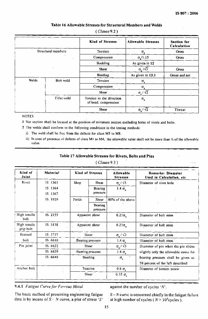
9.2 Structural Members and Welds .,.,
Allowable stresses for structural members and weldsare given in Table 16.
9.3 Rivets, Bolts and Pins
The allowable stresses for rivets, bolts and pins shallconform to the specification as given in Table 17.
9.4 Conventional Number of Cycles and StressSpectrum
The number of cycles of variation of loading and thespectrum of stresses to be taken into considerationfor fatigue stresses. Suitable provision shall be madein the design of the structural member to the protectionagainst cause of the following fatigue failure:
a)
b)
c)
d)
Failure due to maximum tensile stress ofsufficiently high value;
A large enough variation or fluctuation inthe applied stress;
A sufficiently large number of cycles of theapplied stress; and
Protection against stress concentration,corrosion, temperature, over load,metallurgical structure, residual stress andcombined stress.
14
1S 807:2006
Table 16 Allowable Stresses for Structural Members and Welds
( CIause 9.2 )
Kind of Stresses Allowable Stresses Section forCalculation
Structural members Tension Ua Oross
Compression 6,/1.15 Gross
Buckling As given in 12
Shear 0,10 Gross
Bending As given in ‘13.1 Gross and net
Welds Butt weld Tension o,
Compression 0,
Shear Oalfi
Fillet weld Tension in the direction o aof-bead, compression
Shear Is,lfi Throat
NOTES
1
2
Net section shall be located at the position of minimum section excluding holes of rivets and bolts.
The welds shall conform to the followingconditionsin the testing methods:
i) The weld shall be free from the defects for class M5 to M8.
ii) In case of presence of defects of class Ml to M4, the allowable value shall not be more than !4 of the allowablevalue.
Table 17 Allowable Stresses for Rivets, Bolts and Pins
( Clause 9.3) .,
Kind of Material Kind of Stresses Allowable Remarks: Diameter I
Joint Stresses Used in Calculation, etc
Rivet IS 1363 Shop Shear 0,/43 Diameter of rivet hole
IS 1364 Bearing 1.4 Oa I
IS 1367 pressureI
1S 1929 -Fields Shear 80% of the aboveI
Bearingpressure I
High tensile IS 2155 Apparent shear o.21aa Diameterof bolt stembolt I
High tensile IS 3138 Apparent shear 0.2IGl Diameterof bolt stemgrip bolt
Reamed Is 3737 Shear CiaI J3 Diameter of bolt stem
bolt 1s 6610 Bearing pressure 1.40,, Diameter of bolt stem
Pin joint IS 6623 Shear 0,/ d3 Diameter of pin when the pin slides
IS 6639 Bearing pressure 1.40, slightly only the allowable stress for
[S 6649 Bending tra “ bearing -pressure shall be given as
50 percent of the left described
Anchor bolt Tension 0.60, Diameter of bottom screw
Shear 0.35 Cra
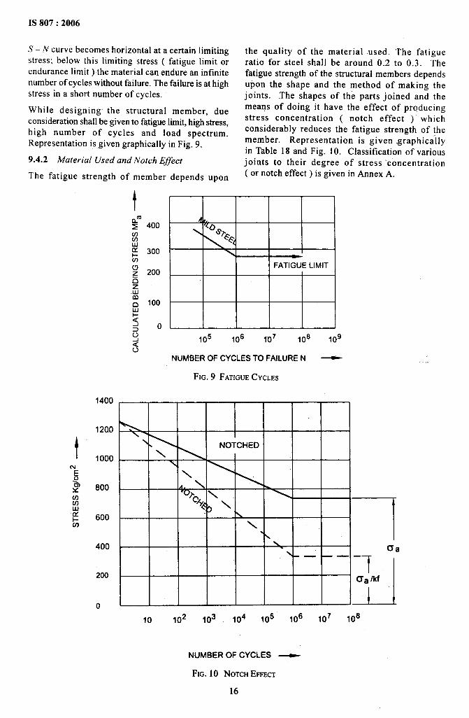
9.4.1 Fatigue Curve for Ferrous Metal against the number of cycles ‘N’.
The basic method of presenting engineering fatigue S– N curve is ccmcerned chiefly in the fatigue failuredata is by means of S – N curve, a plot of stress ‘S’ at high number of cycles ( N > 105cycles ).
15
.——. —:-——... ——.
IS 807:2006
S – N curve becomes horizontal at a certain limitingstress; below this limiting stress ( fatigue limit orendurance limit ) the material can endure an infinitenumber of cycles without failure. The failure is at highstress in a short number of cycles.
While designing the structural member, dueconsideration shall be given to fatigue limit, high stress,high number of cycles and load spectrum.Representation is.given graphically in Fig. 9.
9.4.2 Material Used and Notch Effect
The fatigue strength of member depends upon
1200
u)(nLulx1- 600U-J
400
200
0
1400
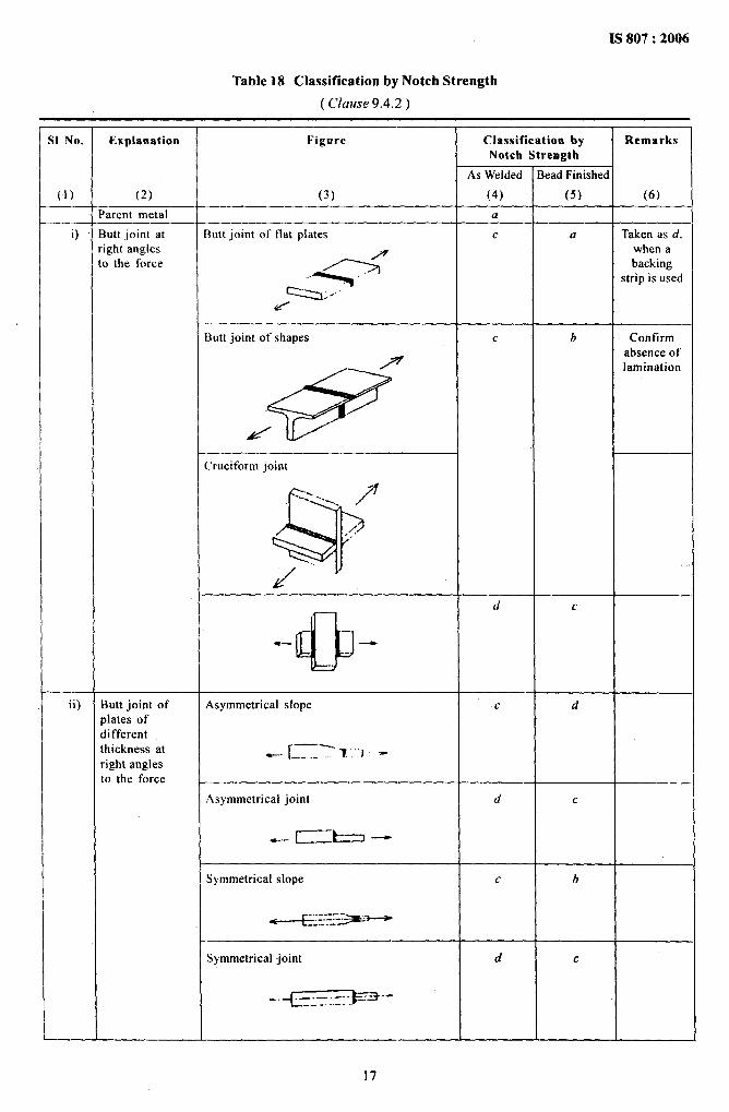
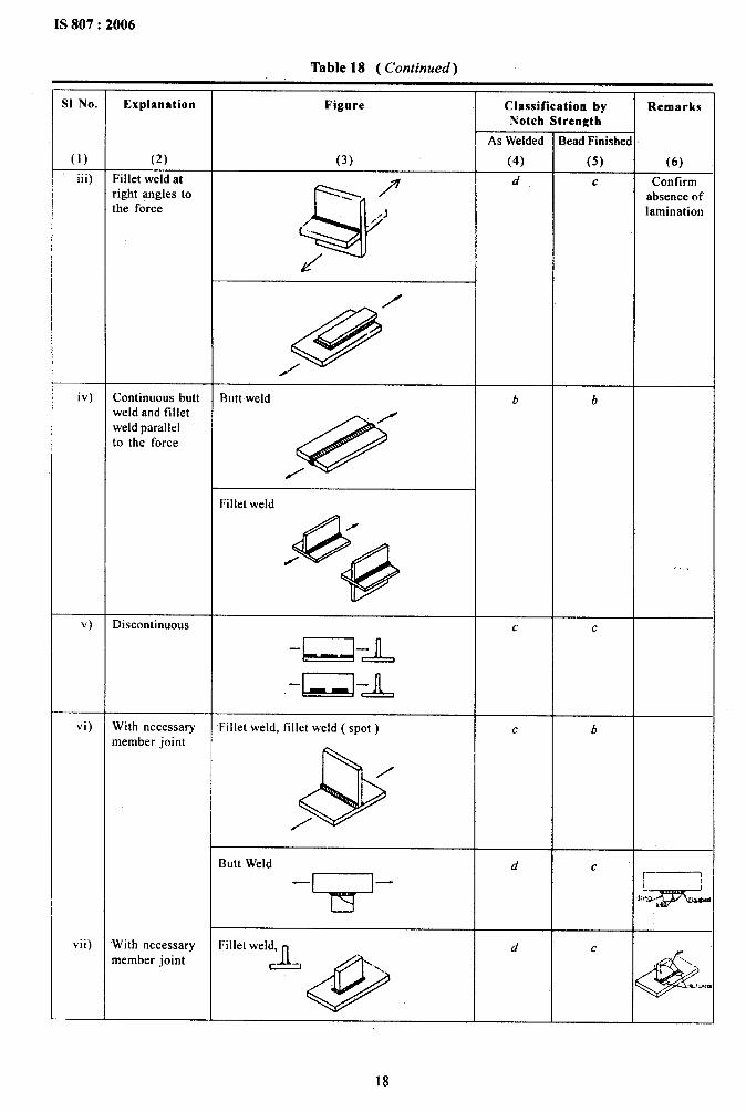
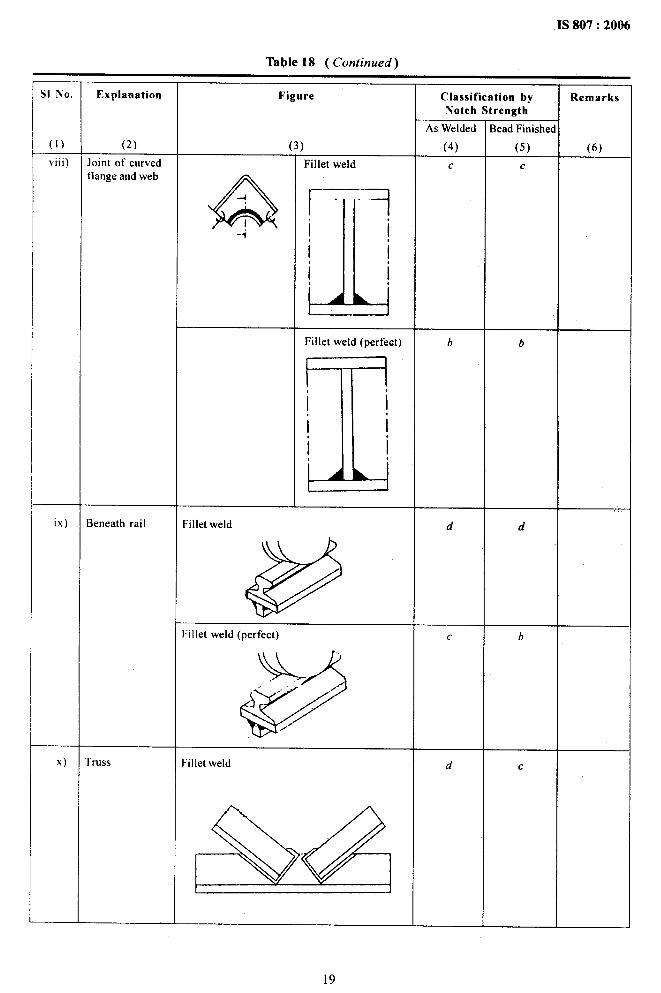
the quality of the material used. The fatigueratio for steel shall be around 0.2 to 0.3. Thefatigue strength of the structural members dependsupon the shape and the method of making thejoints. The shapes of the parts joined and themeans of doing it have the effect of producingstress concentration ( notch effect )“ whichconsiderably reduces the fatigue strength of themember. Representation is given graphicallyin Table 18 and Fig. 10. Classification of variousjoints to their degree of stress ‘concentration(or notch effect ) is given in Annex A.
4/,,.
\
\ -FATIGUELIMIT
,05 ,.6 ,.7 ,.8 ,09
NUMBEROF CYCLESTO FAILUREN ~
FIG. 9 FATIGUECYCLES
10 ,02 ,03 ,04 ,~5 ,.6 ,.7 ,.6
.,. ,
NUMBER OF CYCLES ~
FIG. 10 NOTCH EFFECT
16
IS 807:2006
Table 18 Classification by Notch Strength
( Clause 9.4.2)
S1 No. Explanation Figure Classification by RemarksNotch Strength
As Welded Bead Finished
(}) (2) (3) (4) (5) (6)
Parent metal a
O Butt joint at Butt joint of fiat piates c a Taken as d.right angles when ato the force backing
~y~y strip is used
d
Butt joint of shapes c b Confirm
/absence of
e
lamination
,/
d
Cruciform joint
/
&
.---”.~...
=.
.,<.
= ..
d
d c
*—
0“
ii) Butt joint of Asymmetrical slope c dplates ofdifferentthickness at _ [_~-.- “, “, -right anglesto the force
Asymmetrical joint d c
. ... ~-t-l -
Symmetrical slope c b
* :---=z~~-------
Symmetrical joint d c
17
,
IS 807:2006
Table 18 ( Continued).–
S1 No. Explanation Figure Classification by RemarksNotch Strength
As Welded Bead Finished
(1) (2) (3) (4) (5) (6)
iii) Fillet weld at\ P
Q
d c Confirmright angles to absence ofthe force ) lamination,. .’/’
d
@
/
///
iv) Continuous butt Buttweld b bweld and fillet
/weld parallelto the force
@/
Fillet weld
@
/
/
@
.,. ,
v) Discontinuous c c
-R-L
-D-L
vi) With necessary Fillet weld, fillet weld ( spot) c bmember joint
&
/
/
Butt Weld d c
w [—— — ~1A*>ivii) With necessary Fillet weld,
R’d c
member joint ~
@&
“\.=.
,K,x.,
—.— _-_c__ —.
IS 807:2006
Table 18 ( Continued)
Classification byNotch Strength
RemarksS1 No.
(1)
Explanation Figure
As Welded
(4)
c
3ead Finishe[
(5)
c
.
(2)
loint of curvedflange and web
(6)viii) Fillet weld
A-1
!I!II
-i
IAbFillet weld (perfect) b
I!!
1-
d
.,, ,ix)
x)
3eneath rail Filletweld d
I’illet weld (perfect)
u
GY
h’” ““’” /“’-
bc
rruss Fillet weld d c
19
IS 807:2006
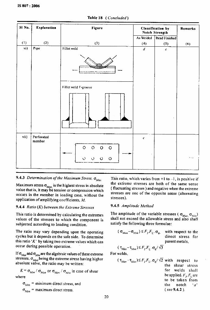
Table 18 ( Concluded) .
S1 No. Explanation Figrme Classification by RemarksNotch Strength
As Welded Bead Finished
(1) (2) (3) (4) (5) (6)
xi) Pipe Fillet weld d c
\ . /
%
.... . . . ,.. . ..
E
—.’. “ ,. ... . . . . . . .--- . . . . . . . . . . .. . . . . . . . . . . . ..—.———.. —
Fillet weld E-groove
JLD
—---
-.-—..—
--—.
xii) Perforatedmember
“---”r:_t”--” c ~~~~
9.4.3 Determination of the Maximum Stress, O~aX
Maximum stress cr~ti is the highest stress in absolutevalue that is, it maybe tension or compression whichoccurs in the member in loading case, without theapplication of amplifying coefficients, M.
9.4.4 Ratio (K) between the Extreme Stresses
This ratio is determined by calculating the extremesvalues of the stresses to which the component issubjected according to loading condition.
The ratio may vary depending upon the operatingcycles but it depends on the safe side. To determinethis ratio ‘K’ by taking two extreme values which canoccur during possible operation.
If a~m and c~,n are the algebraic values of these extremestresses, o~aXbeing the extreme stress having higherabsolute valve, the ratio may be written:
K = ~~,n f o~o, or CT~d,,I o~,. in case of shear
where
‘Mm= minimum direct stress, and
‘Max = maximum direct stress.
This ratio, which varies from +1 to –1, is positive ifthe extreme stresses are both of the same sense( fluctuating stresses) and negative when the extremestresses are one of the opposite sense (alternatingstresses).
9.4.5 Amplitude Method
The amplitude of the variable Stresses ( o&fax~k~,,,)shall not exceed the allowable stress and also shal Isatisfy the following three formulae:
( ~~aX-~~i~ ) S ‘J.F~. Cd- with respect to thedirect stress forparent metals,
( ?w..-~lwn )< ~J.FL. 6d/ wFor welds,
( ~Ma.-rM,,)S ~J.~~. a~/ W with respect tothe shear stressfor welds shallbe applied. FJ, ~~areto be taken fromthe notch ‘u’(see 9.4.2 ).
20
where
a A’4U.K=
~A{(n =
TMu.r =
Tli[lll =
F-, =
FL, =
*d =
maximum direct stress, in kgf/cm2 orN/mmz;
minimum direct stress, in kgf/cm2 orNhnmz;
maximum shear stress, in kgi7cm2 orN/mm2;
minimum shear stress, in kgf/cm2 orN/mmz;
joint factor given in Table 19;
life factor given in Table 20; and
allowable fatigue stress. This should betaken as 1 000 kgf/cm2 or 100 N/mm2.However, each stress shall not exceedthe al Iowable stress.
Table 19 Joint Factors (F’,)
Table 20 Life Factors (F,)
(Clause 9.4.5)
Group of Ml M2 M3 M4 M5 h46 M7 MgCranes
Notches
(1) (2) (3) (4) (s) (6) (7) (8) (9)
a. b 1,3 1.2 1.2 1,1 ].1 1.() 1,() lo
c.d 1.7 1,4 1.4 1.2 ].2 I,o ],() lo
9.4.6 Checking the Members Subjected to /“atigue
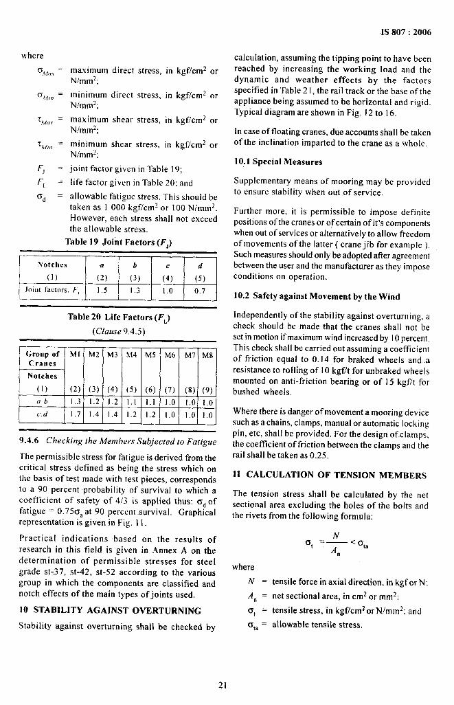
The permissible stress for fatigue is derived from thecritical stress defined as being the stress which onthe basis of test made with test pieces, correspondsto a 90 percent probability of survival to which acoefficient of safety of 4/3 is applied thus: ad offatigue = 0.750, at 90 percent -survival. Graphicalrepresentation is given in Fig. I I.
Practical indications based on the results ofresearch in this field is given in Annex A on thedetermination of permissible stresses for steelgrade st-37, st-42, st-52 according to the variousgroup in which the components are classified andnotch effects of the main types of joints used.
10 STABILITY AGAINST OVERTURNING
Stability against overturning shall be checked by
=1S807:2006
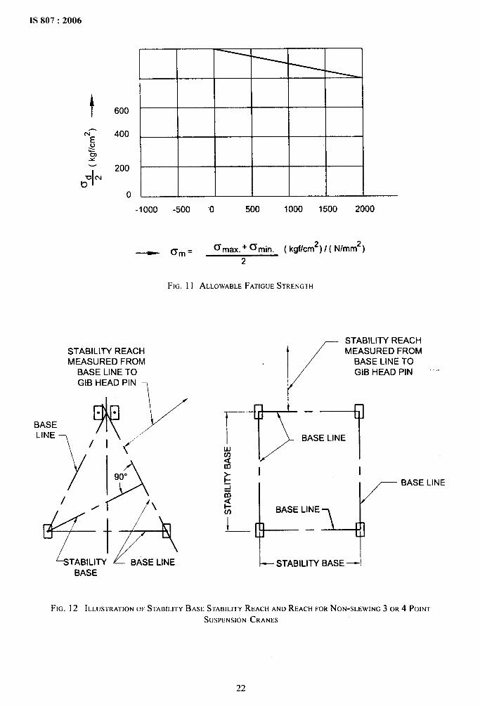
calculation, assuming the tipping point to have beenreached by increasing the working load and thedynamic and weather effects by the factorsspecified in Table 21, the rail track or the base of theappliance being assumed to be horizontal and rigid.
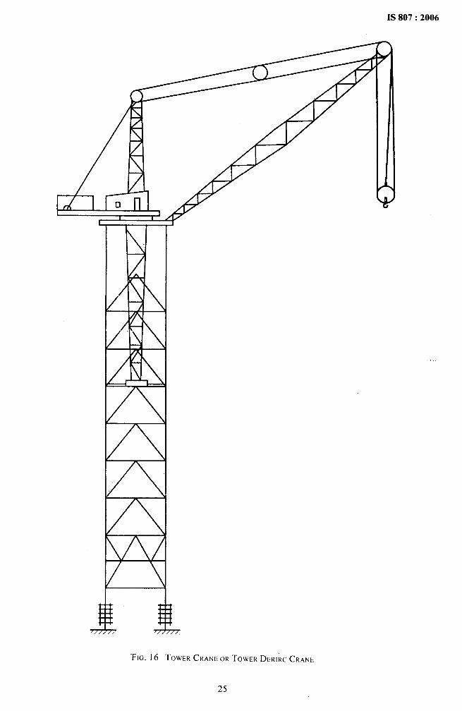
Typical diagram are shown in Fig. 12 to 16.
In case of floating cranes, due accounts shall be takenof the inclination imparted to the crane as a whole.
10.1 Special Measures
Supplementary means of mooring may be providedto ensure stability when out of service.
Further more, it is permissible to impose definitepositions of the cranes or of certain of it’s componentswhen out of services or alternatively to allow freedomof movements of the latter ( crane jib for example ).Such measures should only be adopted atler agreementbetween the user and the manufacturer as they imposeconditions on operation.
10.2 Safety against Movement by the Wind
Independently of the stability against overturning, acheck should be made that the cranes shall not beset in motion if maximum wind increased by 10percent.This check shall be carried out assuming a coefficientof friction equal to 0.14 for braked wheels and aresistance to rolling of 10 kgf/t for unbraked wheelsmounted on anti-friction bearing or of 15 kgf/t forbushed wheels.
Where there is danger of movement a mooring devicesuch as a chains, clamps, manual or automatic lockingpin, etc, shall be provided. For the design of clamps,the coefficient of friction between the clamps and the ‘rail shall be taken as 0.25.
11 CALCULATION OF TENSION MEM-BERS
The tension stress shall be calculated by the netsectional area excluding the holes of the bolts andthe rivets from the following formula:
whereN=
An =
at =
O,a =
NUt =—<qa
An
tensile force in axial direction, in kgf or N:
net sectional area, in cm2 or mmz;
tensile stress, “inkgf/cm2 or N/mmz; and
allowable tensile stress.
IS 807:2006
600
400
200
0
-1000 -500 0 500 1000 1500 2000
~ (Tin= ~m~x. + ~min. ( kgf/cm2) / ( N/mm*)
2
FIG. 11 ALLOWABLEFATIGUESTRENIGTH
STABILITY REACHMEASURED FROM
BASE LINE TOGtB HEAD PIN ,
$)’’”● *BASE
“NE ~ , , ,t
y A\
90°
0 /
+++%
TABILITY BASE LINEBASE
STABILITY REACH
~ 1/
MEASURED FROMBASE LINE TOGIB HEAD PIN ‘“’
~kL’E4l--STABILllY BASE —1
FIG. 12 ILLLJSTRATIONm STABILITYBASE STABILITYREACH ANDREACHFORNON-SLEWING 3 OR 4 POINI-
SUSPENSION CRANES
22
IS 807:2006
STABILITYBASE—.—.——. REACH
\ I STABILITY I II I----=Q 1- ‘EACH-
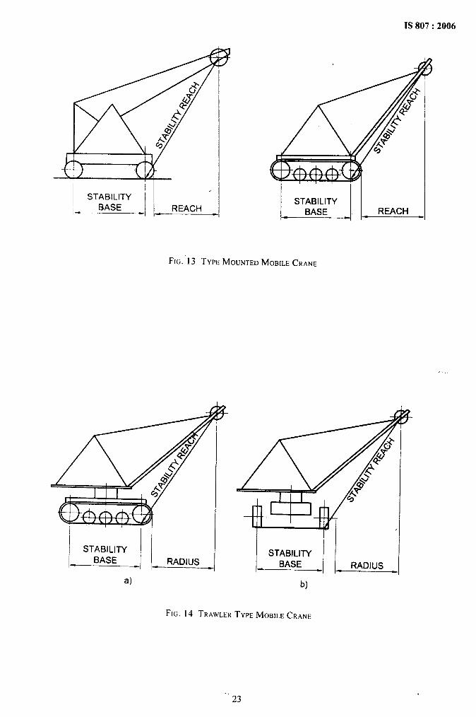
FIG. 13 TYPEMOUNTEDMOBILECRANE
STABILITYBASE RADIUS
a)
I-till lrll/
FT rSTABILITY
BASE - RADIUS
b)
FIG. 14 TRAWLERTYPEMOBILECRANE
.,23
.
7
///
/
J.
,,
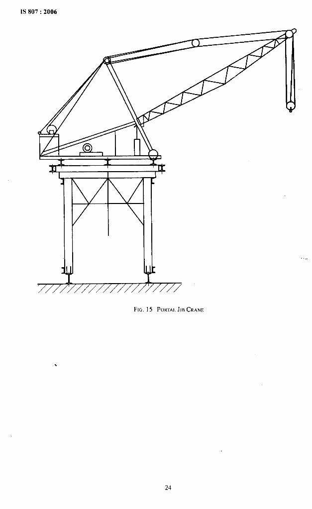
mFIG. 15 PORTALJIB CRANE
,... ._ . —,..,A
.
“FIG. 1(j TOWER CRANE OR TOWER DERIRC CRANE
.,
25
IS 807:2006
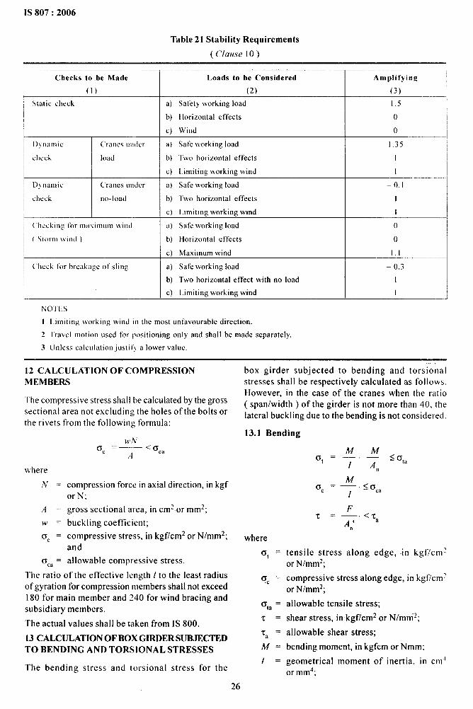
Table 21 Stability Requirements
( C/ause IO)
Checks ‘to .be Made
(1)
Static check
Dynamic Cranes under
check load
D}namic Cranes uudcr
check no-load
~ (’hecking for m2i\inlunl tviudI
( Storm !vincl )
~ Check for breakage of sling
Loads to be Considered Amplifying
(2) (3)
a) Safety working load 1.5
b) Horizontal effects o
c) Wind o
a) Safe working load 1.35
b) Twu horizontal effects I
c) Limiting working wind 1
a) Safe working load -0.1
b) Two horizontal effects I
c) Limiting working wind 1
a) Safe working load ()
b) Horizontal effects o
c) Maximum wind 1.1
a) Safe working load – 0.3
b) Twohorizontal effect with no load I
c) Limiting working wind 1
NOTES
I Limiting working wind ill the most unfavorable direction.
2 Travel motion used for positioning only and shall bc made separately,
3 Unless calculation juslilj a lower value.
12 CALCULATKIN OF COMPRESSION
MEMBERS
The compressive stress shal I be calculated by the gross
sectional area not excluding the holes of the bolts or
the rivets frolm the following formula:
whereN=
A =
w=
Oc =
rsca=
compression force in axial direction, in kgforN;
gross sectional area, in cm2 or mm2;
buckling coefficient;
compressive stress, in kgf/cm2 or N/mm2;and
allowable compressive stress.
The ratio of the effective length /to the least radiusof gyration for compression members shall not exceed180 for main member and 240 for wind bracing andsubsidiary members.
The actual values shall be taken from IS 800.
13 CALCULATION OF BOX GIRDER SUBJECTEDTO BENDING AND TORSIONAL STRESSES
The bending stress and torsional stress for the
box girder subjected to bending and torsionalstresses shall be respectively calculated as follows.However, in the case of the cranes when the ratio( span/width ) of the girder is not more than 40, thelateral buckling due to the bending is not considered.
13.1 Bending
where
at =
a=c
q, =
T=
‘Ta =A/f.
I=
MM6. ‘—. — <(3,2
I An
McJ=— < ~ca
c!“
FT= —. <Ta
An’
tensile stress along edge,or N/mm2;
in kg flcm~
compressive stress along edge, in kgf/cmzor N/mm*;
allowable tensile strkss;
shear stress, in kgf/cm2 or N/mmz;
allowable shear stress;
bending moment, in kgfcm or Nmm:
geometrical moment of inertia, in cm~or mm4;
26

1S807:2006
.’1 =
.4,, =
6’=
~ ,=
A,,’ =
gross sectional area of tension flanges,in cmz or mm2;
net sectional area of tension flanges,in cmz or mm2;
distance between the neutral axis to tensionedge or compression edge, in cm or mm;
shear force. in kgf or N; and
net sectional area of web subjected to shear,in cm? or mm2.
13-.2 Torsion
l~here
T, =
Ta =
M, =
A =
t=
M,q =_ <~
2.A.I a
shear stress due to torsional moment inkgf/cm~;
allowable shear stress;
torsional moment around the shearingcentre in kgf cm or N mm;
area surrounded with centre lines of websand flanges in cm? or mmz; and
thickness of web or flange in cm or mm.
M CALCULATION OF MEMBERS SUBJECTEDTO BENDING BY FORCE IN THE DIRECTIONOF AXIS
Stress of the members subjected to bending by forcein the axial direction shall be calculated from thefollowing formulae or a precise buckling calculationshall be carried out considering the deformation ofthe members as required:
where
0, “
(3=c
crta=N.
M =
1=
A=
An =
N MG=—c .W+O.9 — .e < ~ta
A 1
tensile stress along edge, in kgf/cm2or N/mmz;
compressive stress along edge, in kgf/cm2or N/mmz;
allowable tensile stress;
force in axial directicm, in kgf or N;
bending moment. in kgf-cm or N-mm;
geometrical moment of inertia, in cm4
or mnd;
gross sectional area of member, in cm2or mmz;
net section area of member, in cm2or mm2;
and
e ==distance between the neutral axis and theedge of section, in cm or mm.
Moreover, open section such as 1section member shallbe checked about lateral buckling.
15 CALCULATION OF WELD.ED JOINTS
15.1 Stresses on Joints under Tension, Compressionor Shearing Fcirce
Stresses at the butt weld or the fillet weld shall becalculated from the following formulae:
where
G=
‘r=
p.
a=
1=
Po ‘—
X a.1
PT .—
X a.1
tensile or compressive stress at the weld.in kgf/cm2 or N/mm2;
shear stress at the weld, in kgf/cmz orN/mmz;
force acting on the joint, in kgf or N;
throat of the weld, in cm or mm; and
effective length of the weld, in cm or mm..
15.2 Combined Stresses on Joints under Bendingand Shear Moment
Composite stress shall be calculated from the followingformula for joints on which the bending moment andthe shear force act simultaneously, such as thecontinuous weld connecting a web plate and flange,vertical or horizontal butt weld of webplates and fiIletweld connecting l-shape girder to wall surface:
~s 6,
where
6 = tensile or compressive stress at the weld,in kgf/cm2 or N/mm2;
“O. = bending stress in kgf/cm2 or N/mmz; and
‘c = shearing stress.in kgf/cm2 or N/mmz.
15.2.1 Stress Due to Bending Moment
where
0=
M=
I=
Mc ‘—”Y
[
tensile or compressive stress at the weld,in kgf/cm2 or N/mm2;
bending moment acting at the joint, in kgf-cm;
moment of inertia of the throat around the
27
IS 807:2006
neutral axis andinthe case of fillet weld,
the moment of inertia of expansion effective
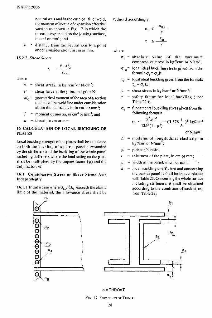
section as shown in Fig, 17 in which the‘throat is expanded on the joining surface,in cm4 or mm4; and
Y ==distance from the neutral axis to a pointunder consideration, in cm or mm.
15.2.2 Shear ,Wress
where
-c=p.
MG =
I=
a=
P A4fGT –—.—
I.CI
shear stress, in ligf/cm2 or N/cmz;
shear force at the joint, in kgf or N;
geometrical moment of the area ofa sectionoutside of the weld line under considerationabout the neutral axis, in cms or mm3;
moment of inertia, in cm4 or mm4; and
throat, in cm or mm.
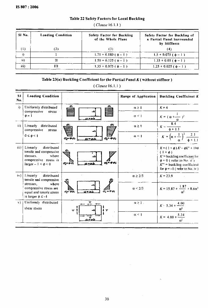
16 CALCULATION OF LOCAL BUCKLING OFPLATES
Local buckling strength of the plates shall be calculatedon both the buckling of a partial panel surroundedby the stiffeners and the buckling of the whole panelincluding stiffeners where the load acting on the plateshall be multiplied by the impact factor (~) and theduty factor, M.
16.1 Compressive Stress or Shear Stress ActsIndependently
16.1.1 In such case where OIL,,fit~i exceeds the elasticlimit of the material, the allowance stress shall be
alt’. /--
reduced accordingly
‘Ikio, s—s
‘ki‘t s—s
where
al =
61k]=
‘k] =
T=
s =
Isc =
E.
P.
t .
b=
k=
I&f}“ 1
\ a3.—
a4~-
absolute value of the maximumcompressive stress in k-gf/cm2or N/cm~;
local ideal buckling stress given from theformula 6, = oC.k;
local ideal buckling given fi-omthe formula~kl= OCk;
shear stress in kgf/cm2 or N/mm*;
safety factor for local buckling ( seeTable 22);
fundamental buckling stress given from thefollowing formula:
CTc=n2.E.t2
=( 1378.: )2,kgf/cmz12b2(l -p2)
or N/mm~
modulus of longitudinal elasticity, inkgf/cm2 or N/mm2;
poisson’s ratio;
thickness of the plate, in cm or mm;
width of the panel, in cm or mm; .,,.,
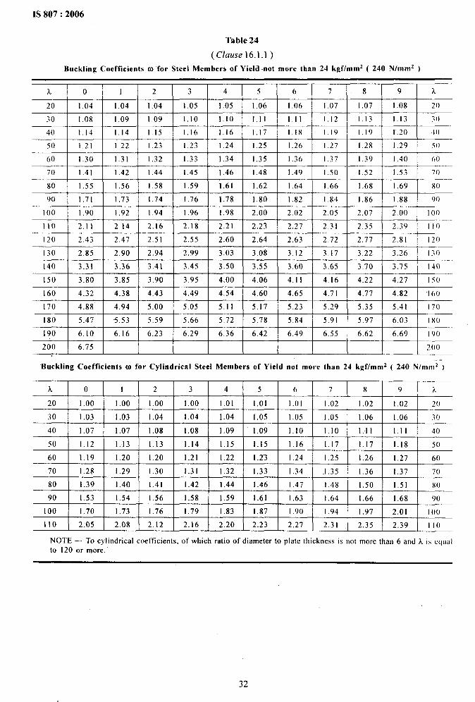
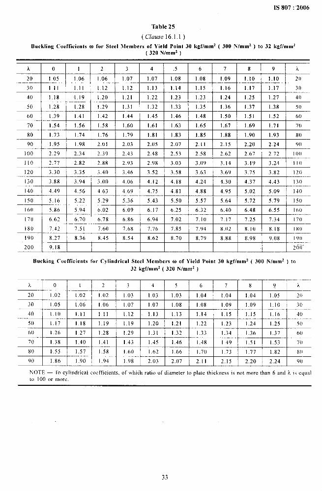
local buckling coefficient and concerningthe partial panel it shall be in accordancewith Table 23. Concerning the whole surfaceincluding stiffeners, it shall be obtainedaccording to the condition of each stressfrom Table 23;
?1
r
l—l-f t
R..a5 1a5
a = THROAT
FIG.17 EXPANSIONOF TIiROKI
28
a=
a=
Y=
J=
s=
F=
NOTE
length of the panel, in cm or mm;
ratio of length to width of the panel;
(1a =—
h
stiffeners ratio of the stiffener;
JY-
0.092 i5t3
geometrical moment of inertia about thecentre line of the plate to calculate thelocal buckling for the gross section of thestiffeners, in cm’ or mm4;
ratio of area of the stiffener;
Fs ‘-—
hi
gross sectional area of the stiffeners in cm2or mm~.
— The values ot’ buckling coefficient shall betaken from Tables 23 [o ?7.
16.2 Normal Stress and Shear Stress ActsSimultaneously
The two local buckling stress. ol~,and ~,~iare separatelycalculated and the local combined stress, o,~i shallbe obtained from the following formula:
-Ovkl=
I+@ IS, +
(d
3-4) a *— _ — ,.
)
-t (:)*4 ‘Ik! 4 Clki ‘ki
where
$ = ratio of maximum to minimum stress actingperpendicular to a plate.
In special case when ~ = O, ov~,= alk,
when o = O, crVk,= i? ~ki
In case where ideal combined stress av~iexceeds the elastic limit of the material theallowable stress shall be determined by thereduced combined stress Ovk
CrCTvk =drJ, ~+3#= ~ 1,in kgflcm~or N/mm2
where
al =
s ——
(sVk =
a=vkl
ok =
,s
absolute value of the maximumcompressive stress in kgf/cmz or N/cm*,
safety factor for local buckling,
reduced combined stress,
ideal combined stress, and
all-owable reduced stress.
IS 807:2006
17 DESIGNS OF STRUCTURAL M-EMBERSSUBJECT TO AXIAL FORCES
The structural members and joints shall be of thestructure free from eccentricity and special stressconcentration, and in the inevitable case, these shal Ibe designed taking into consideration the effect.
17.1 Net Sectional Area of Tension Member
In order to obtain the effective net sectional area ofthe tension member, the areas of the rivet-or the boltholes shall be reduced adequately according to theposition of the rivets or the bolts. In Fig. 17, if thesection a-c-c-a is smaller than that of a-a, four rivetsor bolt holes shall be reduced from the sectional areaof the member.
17.2 Slenderness Ratio
The slenderness ratio k of the member shall becalculated from the following formula:
k= lklk
where
/k = buckling length, in cm or mm; and
k = minimum radius of gyration relating tobuckling axis, in cm or mm.
The buckling length f~shall be obtained as follows:
As to the buckling in aplane of a truss, the buckl,i~glength is taken as lk, which is the distance between ,the centre of gravity of the joining bolts ( includingrivets ) at the ends of the member. When a memberintersects the other members, the intersecting part maybe regarded as rigid in the plane of the truss.
The bend buckling vertical to the plane of the trussshall be as follows:
a)
b)
c)
d)
The distance of nodal points may be takenas /k, if the both ends of the member aresupported not to permit displacement.
[n thecase where one end of the member isjoined rigidly to a lateral member having bendrigidity not to displace laterally, f~shall betaken as 0.81.
In the case where both ends are jointed rigidlyto the lateral members having bend rigiditynot to displace laterally, /k shall be taken as0.71.
In Fig. 18, when the nodal of a and b ofboth trusses do not displace perpendicularlyto the plane of truss and the forces ofmembers N,, Nl are different in magnitudeand N2< NI, it shall taken as
N2/k = (0.75+ 0.25 — )
NI
29
.
IS 807:2006
Table 22 Safety Factors for Local Buckling
( Clause 16.1.1 )
S1 No. Loading Condition Safety Factor for Buckling Safety Factor for Buckling ofof the Whole Plane a Partial Panel Surrounded
by Stiffness
(1) (2) (3) (4)
.i) I 1.71 + 0.180($-1 ) 1.5+0.075($–1)
ii) 11 1.50+0.125($-1) 1.35+0.05($-1)
iii) 111 1.35 +0.075 (($-1) 1.25+ 0.025 (@-l )
Table 23(a) Buckling Coefficient for the Partial Panel K ( without stiffner )
( Clause 16.1.1 )
slNo.
ii)
iii)
iv)
—v)
Loading Condition
Uniformly distributedcompressive stress1#1=1
Linearly distributedcompressive stress
()< @<l
Linearly distributedtensile and compressivestresses, wherecompressive stress islarger -1<$<0
Linearly distributedtensile and compressivestresses, wherecompressive stress areequai and tensile stressis larger @.S-1
Uniformly distributed
shear stress
Range of Application Bsrckling Coefficient K
K=(l+@)K–@K’+ 100
~ ~Jm~
(l+@)K’= buckling coetlicient Iijr.,,,,,~= O ( refer-to No. ), )
a K’” = buckling coefficientfor @= -1 ( refer to No. iv )
u >213 K=23.9
30
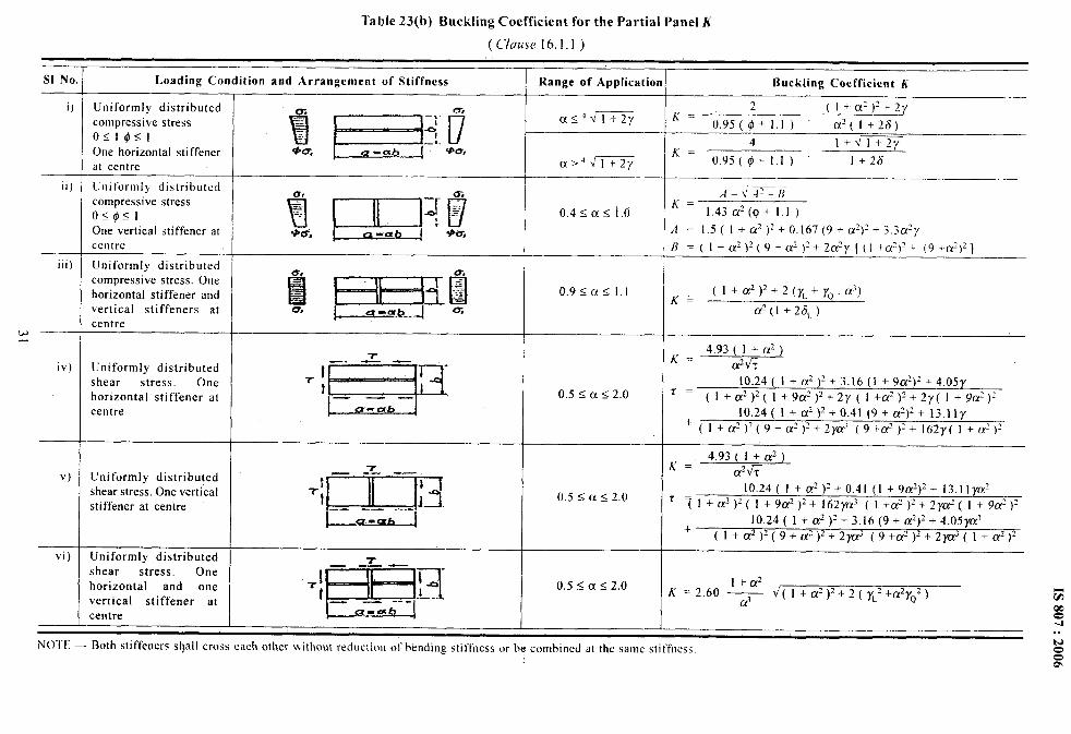
Table 23(b) Buckling Coefficient for the Partial Panel h’
( Clause 16.1.1 )
S1 No
i)
ii)
iii)
w—
iv)
v)
vi)
Loading Condition and Arrangement of Stiffness
Uniformly distributedcompressive stresso<l@l<lOne horizontal stiffenerat centre
Uniformly distributedcompressive stress()<@<]
One vertical stiffener atcentre
Uniformly distributedcompressive stress. Onehorizontal stiffener andvertical stiffeners atcentre
Uniformly distributedshear stress. Onehorizontal stiffener atcentre
Uniformly distributedshear stress. One verticalstiffener at centre
Uniformly distributedshear stress. Onehorizontal and onevertical stiffener atcentre
m. O-*
E ;... —,-... t.--= HI-1—,.=&x a.ab *U,
1 u-u J
Range of Application
a<4dl+2y
0.4 SCIS i,o
0.9 SCX <1.1
0.5 s Cx<2.0
0.5< a 52.0
Buckling Coefficient K
2 (l+cF)~ +27
‘= 0.95 ($$ +1,1) cx~(l +28)
4 I+ N’1+27
‘= o.95(@+l.1) 1+2(5
A = 1.5( I +a2)z+0.167 (9+ Lx:)~+3.3Lx2y
B=(l+az )z(9+az)~L2a:y [(l +a:)o +(9+&)2]
~= (l+a*)~+ 2(yL+yQ. a3)
d(l +26L)
~= 4.93 (l+cP)a%
10.24 ( 1 + a2 )2 + 3.16 (1 +9c#)2 + 4.05yr = (l+a2)2( l+9az)2+ 2y(l+a2)z+2y( I+9LY’)Z
10.24( I +a2 )2+0.41 (9+a~)2+ 1~.lly‘(l+a~)2( 9+a~)z+2ya; (9+a3)z +162y(l+LZ2)~
4.93 (1+az)K=
a’~G10.24( 1 +az )2+0,41 (l+9a~)z+ 13.11 yczz
r ~l+a’)2( 1+9a2)z+ 162yu3( l+az)s+2yaz( l+9aD)210.24 ( 1 + a2)z +3,16(9+ &)2+ 4.05yas
+(I+ Q?)2(9+cr2 )2+2@ (9+ry.2)2+ 2y@(l+a2)2
.l
. .
NOTE — Both stiffeners sl}all cross each other iiithout reduction of hknding stitTness or be combined at the same siiffness. Nzm
IS 807:2006
.
Table 24
(Cluuse 16.1.1)
Buckling Coefficients @ for Steel Members of Yield not more than 24 kgf/mm2 ( 240 N/mm* )
L o 1 2 3 4 5 6 7 8 9 k
20 1.04 1.04 1.04 1.05 1.05 1.06 1.06 I .07 1,07 1.08 20
30 1.08 1.09 I .09 1,10 1.10 1.11 [.11 1,12 1.13 1.13 :()
40 1.14 1.14 1.15 1,16 1.16 1,17 1.18 1.19 1.19 I .20 4(I
50 1.21 1.22 1.23 1.23 1.24 1.25 1.26 1.27 1.28 1.29 50
60 1.30 1.31 1.32 1.33 1.34 1.35 1.36 1.37 1.39 I .40 00
70 1.41 1.42 1.44 1.45 1.46 1.48 1.49 1.50 1.52 1.53 70
80 1.55 1.56 1.58 1,59 1.61 1.62 1.64 1.66 I .68 1.69 80
90 1.71 1.73 1.74 1.76 1.78 1.80 1.82 1.84 1,86 1,88 90
I00 1.90 1.92 I .94 1.96 1.98 2.00 2.02 2.05 2,07 2.00 100
)10 2.11 2.14 2.16 2.18 2.21 2.23 2.27 2.3 I 2.35 2.39 110
120 2.43 2.47 2.51 2.55 2.60 2.64 2,63 2.72 2.77 2.81 1?()
130 2:85 2.90 2.94 2.99 3.03 3.08 3.12 3.17 3.22 3.26 I .30
140 3.31 3.36 3.41 3.45 3.50 3.55 3.60 3.65 3.70 3.75 I 40
150 3.80 3.85 3.90 3.95 4.00 4.06 4.11 4.16 4.22 4.27 150
160 4.32 4.38 4.43 4,49 4.54 4.60 4.65 4.71 4.77 4.82 160
170 4.88’ 4.94 5.00 5.05 5.11 5.17 5.23 5.29 5.35 5.41 170
180 -5.47 -5.53 5.59 5.66 5.72 5,78 5,84 5.91 5.97 6.03 180
I 90 6.10 6.16 6.23 6.29 6.36 6.42 6.49 6.55 6.62 6.69 I ()()
200 6.75 200
,,“Buckling Coefficients 01 for Cylindrical Steel Members of Yield not more than 24 kgf/mm2 ( 240 N/mn12 )
x o 1 2 .3 4 5 6 7 8 9 k
20 1.00 1.00 1.00 1.00 1.01 1.01 1.01 1,02 1.02 I .02 2()
30 1.03 1.03 1.04 1.04 1.04 1.05 1.05 1.05 1.06 1.06 3()
40 1.07 1.07 1.08 1,08 1.09 1.09 1.10 1,10 1.11 1.11 40
50 1.12 1.13 1.13 1.14 1.15 1.15 1.16 1,17 1.17 1.18 50
60 1.19 1.20 1.20 1.21 1.22 1.23 1.24 1.25 1.26 1.27 60
70 1,28 1.29 1.30 1.31 1.32 1.33 1,34 .1.35 1.36 1,37 70
80 1.39 1.40 1.41 1.42 1.44 1.46 1.47 1.48 1.50 1,51 X()
90 1.53 1.54 1.56 1.58 1.59 1.61 1.63 1,64 1.66 1.68 90
100 1.70 1.73 1.76 1.79 1.83 1.87 1.90 1.94 1.97 2.01 I00
110 2.05 2.08 2,12 2.16 2.20 2.23 2.27 2.31 2.35 2.39 110
NOTE — To cylindrical coefficients, of which ratio of diameter to plate thickness is not more than 6 and k is equal
to 120 or more.
32
,
1S 807:2006
Table 25
(Clause 16.1.1)
Buckling Coefficients 02 for Steel Members of Yield Point 30 kgf/mmz ( 300 N/mm* ) to32 kgf/mm2( 320 N/mmz )
A o 1 2 3 4 .5 6 7 8 9 L
20 ! 1.o5 \ 1.06 I 1.06 ! 1.07 I 1.07 I 1,08 I 1.08 I 1,09 I 1.10 I 1.10 \ 20
30 I I.it j I.11 I 1.12 I 1.12 I 1.13 ] 1.14 I 1.15 I 1.16 I 1.17 I 1.17 ] 3()
40 I 1.18 I 1.19 I 1.20 ] 1.21 I 1.22 I 1.23 I 1.23 I 1,24 I 1.25 ! “1.27 I 40
50 I 1.28 I 1.28 I 1.29 I 1.31 I 1,32 I 1.33 I 1.35 I 1,36 I 1.37 ] 1.38 I 50
60 \ 1.39 I 1.41 I 1.42 I 1.44 I 1.45 I 1.46 I 1.48 I 1.50 I 1.51 I 1.52 I 60
70 I 1.54 \ 1.56 I 1.58 I 1.60 I 1.61 I 1,63 I 1.65 I 1.67 I 1,69 I 1.71 \ 70
80 I 1.73 I 1.74 I 1.76 I 1.79 I 1.81 I 1.83 I 1.85 I 1,88 I 1.90 I 1.93 I 80
!—–, — -, —.., —.-, ,— —-!90 1.95 1.98 2.01 2.03 I 2.05 I 2.07 I 2.11 I 2.15 \ 2.20 I 2.24 ! ()()
100 2.29 2.34 2.39 2.43 \ 2.48 \ 2,53 I 2.58 I 2.62 I 2.67 I 2.72 ] 100
110 2.77 2.82 2.88 2.93 2.98 3.03 3,09 3.14 3,19 3.24 110
120 3.30 :.35 3.40 3.46 3,52 3.58 3.63 3.69 3.75 I 3.82 120
130 3.88 3.94 3.00 4.06 4.12 4.18 4.24 4.30 4.37 4.43 130
140 4.49 4.56 4,63 4.69 4.75 4.81 4.88 4.95 5.02 5.09 140
150 5.16 5.22 5.29 5.36 5.43 5.50 5.57 5.64 5.72 5,79 150
160 5.86 5.94 6.02 6,09 6.17 6.25 6.32 6.40 6.48 6.55 I60
170 6.62 6.70 6.78 6.86 6.94 7.02 7.10 7.17 7.25 7.34 170
180 7.42 7.51 7.60 7.68 7.76 7.85 7,94 8.02 8.10 8.18 180
190 8.27 8.36 8.45 8.54 8.62 8.70 8.79 8.88 8.98 9.08 I ()()
200 9.18 2i)i)”
Bucking Coefficients for Cylindrical Steel Nlembers to of Yield Point 30 kgf/mm2 ( 300 N/mmz ) to
32 kgf/mm2 ( 320 N/mmz )
L () I 2 3 4 5 6 7 8 y A
20 1.02 1.02 1.02 1.03 1.03 1.03 1.04 1.04 1.04 1.05 ?()
30 1.05 1.06 1.06 1,07 1.07 1.08 1.08 1.09 1.09 1,10 3()
40 1.10 1.11 1.11 1.12 1.13 1.13 1.14 1.15 1.15 1.16 40
50 1.17 1.18 1.19 1.19 1.20 1.21 1.22 1.23 1,24 1.25 5()
60 1.26 1.27 1.28 1,29 1.31 1.32 1.33 1.34 1.36 1.37 60
70 1.38 1.40 1.41 1 43 1.45 1.46 1,48 149 1.51 1.53 70
80 1.55 1.57 1.58 1.60 1.62 1.66 I .70 1.73 1.77 1.82 8()
90 1.86 1.90 1.94 1.98 2.03 2.07 2.11 2.15 2.20 2.24 90
NOTE — To cylindrical coetTicients, Of which ratio Of diameter to plate thickness is not more than 6 -and k is eqLIal
to I00 or more,
33
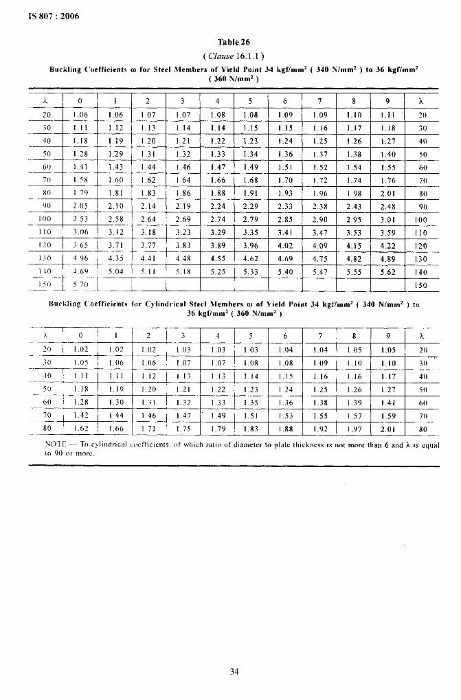
IS 807:2006
.
Table26
(Cluuse 16.1.1)
Buckling Coefficients o) for Steel .Members of Yield Point 34 kgf/mm2 ( 340 N/mmz ) to 36 kgf/mm2( 360 N/mmz )
—k o 1 2 3 4 5 6 7 8 9 k
Z() 1,06 1,06 I .07 1.07 1.08 1.08 1.09 .1.09 1.10 1.11 20
30 Ill 1.12 1.13 1.14 1.14 1.15 1.15 1.16 1.17 1.18 30
40 1,18 1.19 1.20 121 1.22 1.23 1.24 1.25 1.26 1.27 40
5() 1.28 1.29 1.31 1.32 1.33 1.34 1.36 1.37 1.38 1.40 50
60 1.41 I .43 i .44 1.46 1.47 I .49 1.51 1.52 “1.54 1.55 60
70 1.58 1.60 1.62 1.64 1.66 1.68 1.70 1.72 1.74 1.76 70
80 I .79 1,81 1.83 1.86 1.88 1.91 ],93 1.96 1.98 2.01 80
90 2.05 2.10 2.14 2.19 2.24 2.29 2.33 2.38 2.43 2.48 9()
10() 2.53 2,58 2.64 2.69 2.74 2.79 2.85 2,90 2.95 3,01 1()()
110 3.06 3.12 3.18 3.23 3.29 3.35 3.41 3.47 3.53 3.59— 110
120 3.65 3.71 3.77 3.83 3.89 3.96 4.02 4,09 4.15 4.22 120
130 4,96 4,35 4.41 4.48 4.55 4.62 4.69 4.75
+
4.82 4.89 130
1-1o 4.69 5.04 5.11 5.18 5.25 5.33 5.40 5.47 5.55 5.62 140
150 5.70 [50—
Buckling t’ocfficients for Cylindrical Steel Members w of Yield Point 34 kgf/mm2 ( 340 N/mmz ) to36 kgf/mm2 ( 360 N/mmz )
.A () 1 2 3 4 5 6 7 8 9 k-
——20 I,02 1.02 I .02 1.03 1.03 1,03 1.04 I .04 1.05 I .05 20
3() 1,05 1.06 1.06 1.07 1.07 1.08 1.08 1.09 1.10 1.10 30” “
40 1.11 1.11 1.12 1.13 1.13 1.14 1.15 1.16 1,16 1,17 40—.5() 1.18 1.19 1.20 1.21 1.22 1.23 1.24 1.25 1.26 1.27— 50
60 1.28 1,30 1.31 1.32 1.33 1.35 1.36 1.38 1.39 1.41— 60
7() 1.42 1,44 1.46 1.47 1.49 1.51 1.53 1.55 1.57 1.59 70
80 I .62 1.66 1.71 1.75 1.79 1,83 1.88 1.92 1.97 2.01 80
Nol E — To cylindrical ctwt’tlcients. of which ratio of diameter to plate thickness k not more than 6 and A.is equal[0 90 or mm
34

. . __ .—— - --
,
IS 807:2006
Table 27
(Clause 16.1.1)
Buckling Coefficients w for Steel Members of Yield Point 44 kgf/mmz ( 440 N/mm* ) to 46 kgf/mm2( 460 N/mmz )
20 I 103 I 1.o4 I 1.04 I 1.o5 I 1.o6 I 1.06 I 1.07 I 1.07 I 1,09 I 1.09 I ?()I 1
30 1.09 1.10 1.11 1.12 1.13 1.13 1.14 1.15 1.16 1.17 30
40 1.18 1.19 1.20 1.21 1.23 1.24 1.25 1.26 1.28 1.29 40
50 1.30 1.32 1,33 1.35 1.37 1.38 1.40 1.42 1.44 1.46 50
60 1.47 1.49 1.51 1.54 1.56 1.58 1.60 1.62 1.65 1.67 60
70 1.70 1.72 1.75 1,77 1.80 1.83 1.88 1.93 1.98 2.03 70
80 2.08 2.14 2.19 2.24 2.30 2..35 2.41 2.47 2.52 2.58 X()
90 2.64 2.70 2.76 2.82 2.88 2.94 3.00 3.06 3.13 3.19 90
100 3.26 3.32 3.39 3.46 3.52 3.59 3.66 3.73 3.80 3.87 I00
Ilo 3.94 4.01 4,09 4.16 4,23 4,31 4.“38 4.46 4.53 4.61 110
120 4.69 4.77 4.85 4.93 5.01 5.09 5.17 5.25 5.34 5.42 [Z() -
130 5.50 5.59 5.67 5.76 5.85 5.94 6.02 6.11 6.20 6.29 130
140 6.32 6.47 6.57 6.66 6.75 6.85 6.94 7.04 7,13 7.23 140
150 7.33 150
Buckling Coefficients for Cylindrical Steel Members (o of Yield Point 44 kgf/mm2 ( 440 N/mm2 ) to
46 kgf/mm2 ( 460 N/mmz )
?& o “1 2 3 4 5 6 7 8 9 a.
20 loo 1.00 I .00 1.00 1.01 I.ol 1.01 1,02 1.02 1.03 M’
30 1.03 1.04 1.05 1.05 1.06 1.06 I .07 1.08 1.08 1.09 3()
40 1.10 1.11 1.12 1,12 1.13 1.14 1.15 1.16 1.17 1.18 40
50 1.20 1.21 1.22 1.23 1.25 .1.26 1.27 1.29 1.30 1.32 “50
60 1.34 1.35 1.37 1.39 1.41 1,43 I .45 1.47 1.51 1,55 60
70 !.60 1.64 1.67 1.74 1.78 1.83 1.88 1.93 1.98 2.03 -70
N(3TE — To cylindrical coefficients, of which ratio of diameter to plate thickness is not more than 6 and k is equalto 80 or more.
35
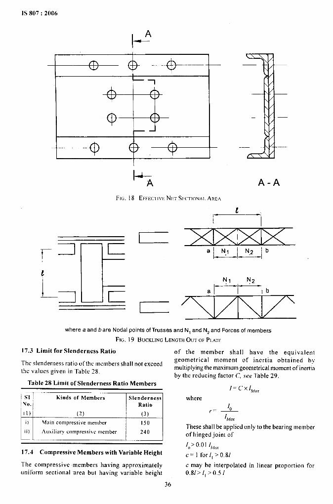
IS 807:2006
.
A“t--
.+__Q--+-@---
1-A
FIG. 18 EFFECTIVENET SECTIONALAREA
l—I I
where a and b are Nodal points ofTrusses and N, and N2and Forces of members
FIG. 19 BUCKLINGLENGTHOUT OF PLATE
17.3 Limit for Slenderness Ratio
The slenderness ratio of the members shall not exceedthe values given in Table 28,
Table 28 Limit of Slenderness Ratio Members
S“l Kinds of MembersNo. /
(1) (2)
i) Main compressi},e member
ii)1
Auxiliary compressive member
SlendernessRatio
-JL-.-l150
240
17.4 Compressive Members with Variable Height
The compressive members having approximatelyuniform sectional area but having variable height
of the member shall have the equivalentgeometrical moment of inertia obtained bymultiplying the maximumgeometrical moment of inertiaby the reducing factor C, see Table 29.
l=cxlMar
where10~. _
IMUXThese shall be applied only to the bearing memberof hinged joint of
10>0.01 Ih,ur
c= 1 forll >0.8/
c may be interpolated in linear proportion for0.81~11 ~0.51
36
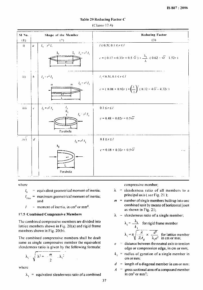
1S 807:2006
Table 29 Reducing Factor C
(C/ausc 17.4)
il Nu. Shape of Ibc Member Reducing Factor
(1) (~) (3)
i) (r l,, ,=/.21. 1<0.51,0.l<r<l
s’””
k(=(().17+ 0.33r+().5~)+~ (0,62+~– 1.52r)
k
ii) b I,)= rzll /,<o.5/. o.l<rs/
II 1[, =r~ll
-’Ea-
(,)
:
c = ( 0.08 + 0.92r ) +. ~ ( ().32 + 4&4.32r )
L
iii) c 10= r: [1 II O.l<r<lIt,
I I()=r:ll
m
~ = ().48 + 0.02r + o.~~— .
L
I)ilrabola
,.i)) d [o=r2[ O.l<r<l
1,~= 13,18 + 0.32r+ 0.5W
-la
.,, ,
.—
L
I)mabola
where
10 = equivalent geometrical moment of inertia;
1,AI’m = maximum geometrical moment of inertia;and
I = moment of inertia. in cm4 or mm4.
17.5 Combined Compressive Members
The combined compressive members are divided intolattice members shown in Fig. 20(a) and rigid framemembers shown in Fig. 20(11).
The combined compressive members shall be dealtsame as single compressive member the equivalentslenderness-ratio is given by the following formula:
where
k, = equivalent slenderness ratio of a combined
37
~=
m=
~=
e=
kl =
d=
A=
compressive member;
slenderness ratio of.all members to aprincipal axis ( see Fig. 21 );
number of single members built up into onecombined unit by means of horizontal jointas shown in Fig. 21;
slenderness ratio ofa single member;
k, = ~ for rigid frame member
~l=nm2~:%:idistance between the neutral axis to tensionedge or compression edge, in cm or mm;
radius of gyration of a single member incm or mm;
length ofa diagonal member in cm or mm:
gross sectional area of a compound memberin cm2 or mm2;
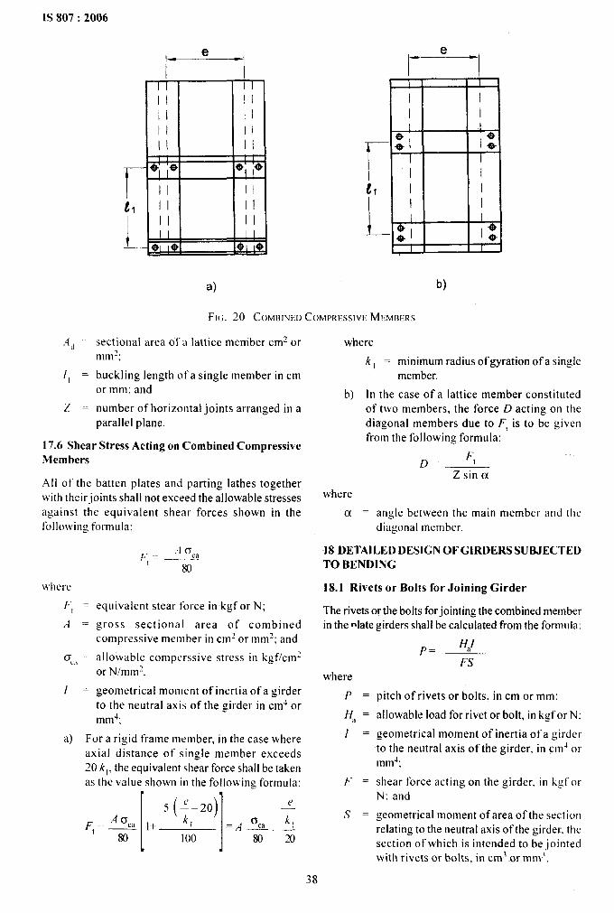
——.—-———
IS 807:2006
e.—
I I
II II
II II
il !1
II IIII II1 1 ! 1
- *’ ‘e 49’ ‘+
II II
t, II II1 II II
L_ ‘; :+II
61 1+
e———
$ I I
I II II I
r ~:1 1:II
tl I I
L ~
II
0,* 1$
I
a) b)
F’1~.20 COMBINW COMPRHSIVE MFMFERS
.4~ = sectional area of a lattice member cm2 ormmz;
II = buckling length ofa single member in cmor mm; and
Z = number of horizontal joints arranged in aparallel plane.
17.6 Shear Stress Acting on Combined CompressiveMembers
All of the batten plates and parting lathes togetherwith their ioints shall not exceed the allowable stressesagainst the equivalent shear forces shown in thefollowing forlmula:
w41ere
F, =
,4=
0=c<1
1=
I80
equivalent stear force in kgf or N;
gross sectional area of combinedcompressive member in clmzor mm?; and
allowable comperssive stress in kgf/cmlor N/mm7.
geometrical moment of inertia of a girderto the neutral axis of the girder in cm4 ormm~;
a) For a rigid .frame member, in the case whereaxial distance of single member exceeds20 kl, the equivalent shear force shall be takenas the value shown in the following formula:
● .
II5 [;-20) ~
~,=q ,+ , =/4%. !180 100 8020
where
k, = minimum radius of gyration of a sing,lemember.
b) In the case of a lattice member constitutedof two members, the force D acting on thediagonal members due to F, is to be givenfrom the following formula:
D= ‘tZ sin a
where
a = angle between the main member and t]lc
diagonal member.
18 DETAILE-D DESIGN OF GIRDERS SUBJECTEDTO BENDING
18.1 Rivets or Bolts for Joining Girder
The rivets or the bolts forjointing the combined memberin the relategirders shall be calculated from the formula:
where
P=
Ha =
1=
F=
s =
FS
pitch of rivets or bolts, in cm or mm:
allowable load for rivet or bolt, in kgf or N:
geometrical moment of inertia of a girderto the neutral axis of the girder, in cmJ ormtm4;
shear force acting on the girder, in kgforN; and
geometrical moment of area of the sectionrelating to the neutral axis of the girder. thesection of which is intended to be jointedwith rivets or bolts, in cm~ or mm;,
38
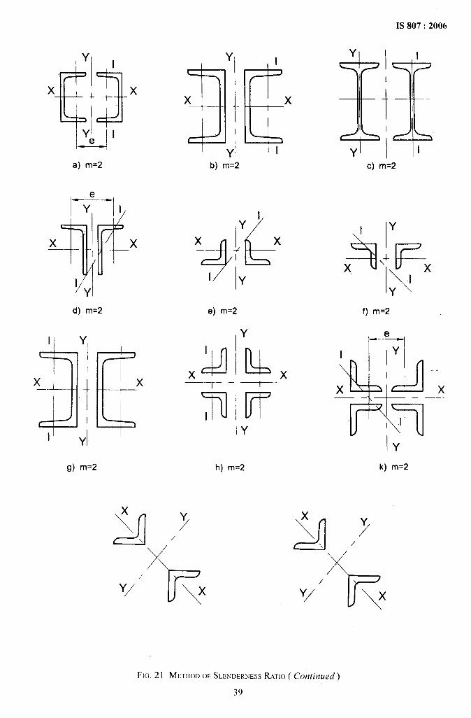
1S 807:2006
YI ,
1,3x L x
a) m=2
el——----
YI
x
-\#
x
IYI
d) m=2
1] Y,
31Ex’_.L--
t
x1“
11 yl I
g) m=2
Y
3’x 1Y!
b) m=2
1P)’x Jx+jJk
I y
.e) m=2
1,
x C=d—T –
7I
x
Y Y\ /
Y/“ % \ x
Y
u x
FrIY
h) m=2
c) m=2
Y
$iHF\4-
\
xI
Y
f) m=2
I Y
*--
.,,,
x x——
,1
IY
k) m=2
x
A Y\ /
Y/‘ 7-\x
FIG. 21 MFTHOD OF SL~ND~RNESSRATIO ( Continued)
39
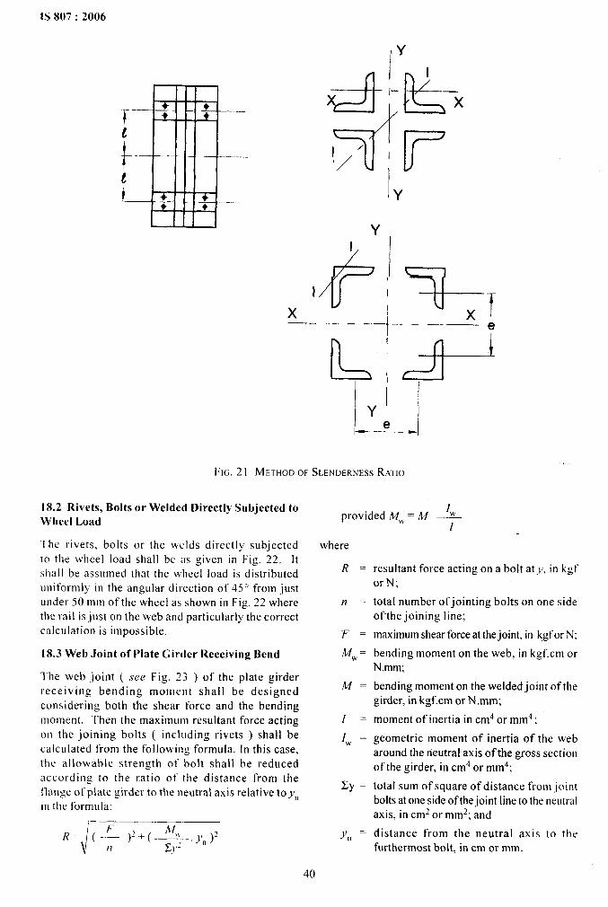
IS 807:2006
G!P-lik-.T@‘/’ ‘
Y
~ 4+”%,Xe—_. ___
F1ci.21 METHOD OF SWNDERN~SSRATIO
18.2 Rivets, Bolts or Welded Directly Subjected to
Wheel Load
‘[he rivets, bolts or the welds directly subjected
to the wheel load shall be as given in Fig. 22. Itshall be assu[med that the wheel load is distributeduniformly in the angular direction of 45° from justunder 50 mm of the wheel as shown in Fig. 22 wherethe rail is just on the web and particularly the correctcalculation is impossible.
18.3 Web Joint of Plate Girder Receiving Bend
The web joint ( see Fig. 23 ) of the plate girderreceiving bending moment shall be designedconsidering both the shear force and the bendingmoment. Then the maximum resultant force actingon the joining bolts ( including rivets ) shall becalculated from the following formula. In this case,the allowable strength ot- -bolt shall be reducedaccording to the fiatio ot- the distance from thetlange of plate girder to the neutral axis relative toynin the formula:
Iwprovided M,k= h4 —
[
where
R=
n=
~=
~w .
~.
I=
Iw =
Ey =
Y“ =
resultant force acting on a bolt atJ, in kgforN;
total number of jointing bolts on one sideof-the joining line;
maximumshear force at thejoint, in kgfor N:
bending moment on the web, in kgf. cm orN.mm;
bending moment on the welded joint of thegirder, in kgf.cm or N mm;
moment of inertia in cm4 or mm4;
geometric moment of inertia of the webaround the neutral axis of the gross sectionof the girder, in cm4 or mm4;
total sum of square of distance from jointbolts atone side of thejoint line to the neutralaxis, in cmz or mm2; and
distance from the neutral axis to thefurthermost bolt, in cm or mm.
40
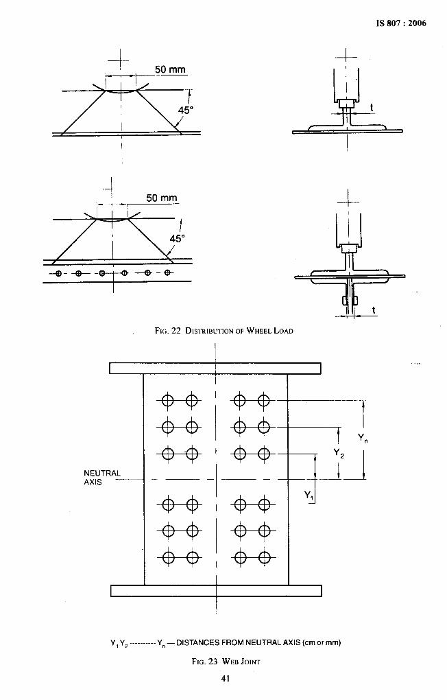
.
4--
I
--1-.-50 mm
.ITL
/ ,--Q--t%----e-t-o---e-*
--1-
A t--1--
I
FIG.22 DISTRIBUTIONOFWHEELLOAD
,,I
NEUTRALAXIS
——-——
I
II
+---4’ 4+”
-+-+ +--+-
+---+ ’+-+—
‘+--4+----i
Y,-J
Y, Y2 ----------Yn — DISTANCES FROM NEUTRAL AXIS (cmor mm)
FIG.23 WEBJOINT
41
IS 807:2006
19 WELDING OF IN.DIJSTRIAL AND M-ILLCRANES
19.1 The following points shall be taken intoconsideration:
a)
b)
c)
d)
19.2
Weldability classification of qualified steel;
Allowable stress in welds;
Fatigue stress in welds; and
Classification of welded joints
1) Weld joint design.
2) Weld joint category.
Weld joint design. welding procedure andinspection of welds given in Annex B.
20 LIMITING DEFLECTiON
‘The deflection of members or the structure as awhole ( without taking into consideration the impactfactor ) should not be such as would impair the strengthor efficiency of the structure or lead to damage totlnishing.
The maximum vertical deflection of the girderproduced by the dead load. the weight of the trolleyand the rated load shall not exceed 1/750 of the spanof the crane ( if the span of the cranes is more than12 m), and 1/600 of the span ( if the span of the craneis less than 12 m ).
21 CAMBERS
Girders shall be cambered to an amountapproximately equal to the dead load deflectionplus one-half the live load deflection.
22 DIAPHRAGMS AND VERTICAL STIFFNESS
The spacing of vertical web stiffness shall notexceed
800 [
6
where
I = thickness of one web plate, in mm; and
v = shear stress in web plate, in kg/cm2.
If the spacing exceeds 1.75 m or depth of the web (h),whichever is greater, web plate shall be reinforced withfull depth diaphragms at major load points.
22.1 Diaphragms
The distance between the adjacent diaphragm ( longer/short ) shall not exceed
7600 S
w
where
S = section modules of rail, in mm3;and
W = maximum trolley wheel load, in kg( withoutimpact ).
Short diaphragm shall be placed between the fulIdepthdiaphragm to support the bridge rail. All diaphragmsshall bear against the top cover plate and shall be weldedto the web plates.
23 GIRDER END -CONNECTION
A substantial end tie must be provided to givehorizontal tixed end for rigidity to girder. The girderswith the truck shall be provided by the large gussetplate welded to the bottom of the truck and attachedto girders with bolts in reamed holes.
24 BRIDGE TRUCKS
The cranes having bogie trucks, the wheel base ismeasured from centre line to centre line of the twowheels which are far apart on the runways.
Cranes with fixed bogie trucks require a flexible endconnection to obtain the equalizing effec~. Craneswith equalizing bogie trucks require a rigid endconnection.
24.1 Ratio of Crane Span to End C-arriage WheelBase
Following condition to be considered:
a) For cranes up to and including 20 m spannot less than one-sixth of the span;
b) For cranes over21 m span and up to 24.5 m,not less than 3.5 m of the span; and
c) For cranes over 24.5 m span not less thanone-seventh of the span.
24.2 Bridge and Gantry Rails
‘ The selection of bridge rails as well as gantry railsdepends upon the wheel load ( maximum) and wheeldiameter. The rails shall be selected based on the IRS( Indian Rail Steel ), CR ( Crane Rail ) or equivalentrails for both for bridge rails as well as gantry rails.The bridge rail shall be attached to the bridge girdersby means of alternately spaced rail clips that arewelded to the girder or attached with welded studs.The welding of clips are preferred. It is recommendedthat the bridge rails shall be supported on wear platewelded on top of the top cover plate and positionedabove each girder diaphragm, so that the bendingstress produced in the rail by trolley wheel load isnot transmitted into the top cover plate.
25 WELDED BOX GIRDERS
Welded box girders ( Fig. 24 ) shall be fabricated ofstructural steel with continuous ( full penetration buttand fillet welds ) longitudinal welds running the fulllength of the girders. All welds shall be designed formaximum shear and bending.
42
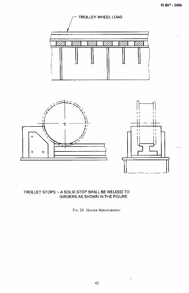
.[
TROLLEY WHEEL LOAD
++t
n----nII IIII II
di=d=lIi II II
II 11” h
l!!dl.,,—
TROLLEY STOPS :-A SOLID STOP SHALL BE WELDED TOGIRDERS AS SHOWN IN THE FIGURE
FIG.24 GIRDERARRANGEMENT
43
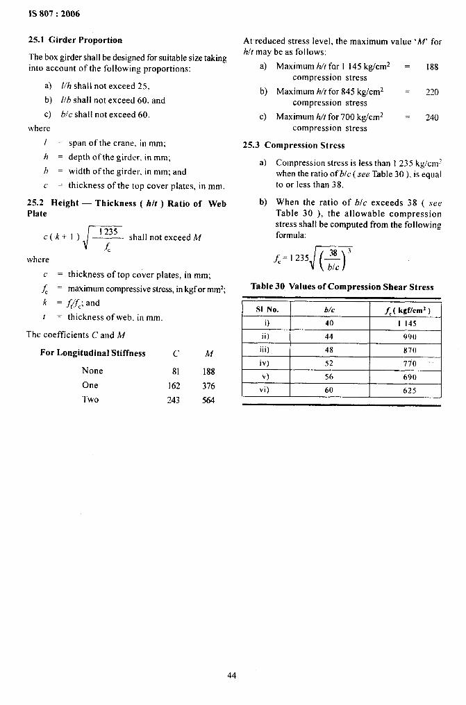
1S 807:2006
25.1 Girder-Proportion
The box girder shall be designed for suitable size takinginto account of the following proportions:
a) //h shall not exceed 25,
b) I/b shall not exceed 60, and
c) bfc shall not exceed 60.
where
[=
h=
b=
c=
span of the crane. in mm;
depth of the girder. in mm;
width of the girder. in mm; and
thickness of the top cover plates, in mm.
25.2 Height — Thickness ( h/t ) Ratio of WebPlate
J 1235C(k+l) shall not exceed M
&where
= thickness of top cover plates, in mm;
~ = maximum compressive stress, in kgf or mm2;c
k = f~f,; and
t = thickness of web. in mm
The coefficients C and M
For Longitudinal Stiffness
None
One
Two
c M
81 188
162 376
243 564
At reduced stress level, the maximum value ‘M’ forhlt maybe as follows:
a) Maximum h/t for I 145 kg/cm2 = 188compression stress
b) Maximum h/tfor 845 kg/cm2 = 220compression stress
c) Maximum h/t for 700 kg/cm2 –— 240compression stress
25.3 Compression Stress
a)
b)
Compression stress is less than I 235 kg/cmzwhen the ratio of b/c ( see Table 30 ), is equalto or less than 38.
When the ratio of blc exceeds 38 ( seeTable 30 ), the allowable compressionstress shall be computed from the followingformula:
J( )38 ~
~=1235 —blc
Table 30 Values of Compression Shear Stress
S1 No. b/c f, ( kgf/cm2 )
i) 40 1 145r
ii) 44 99()
iii) 48 x70 Iiv) 52 770
v) 56 690
vi) 60 625
44
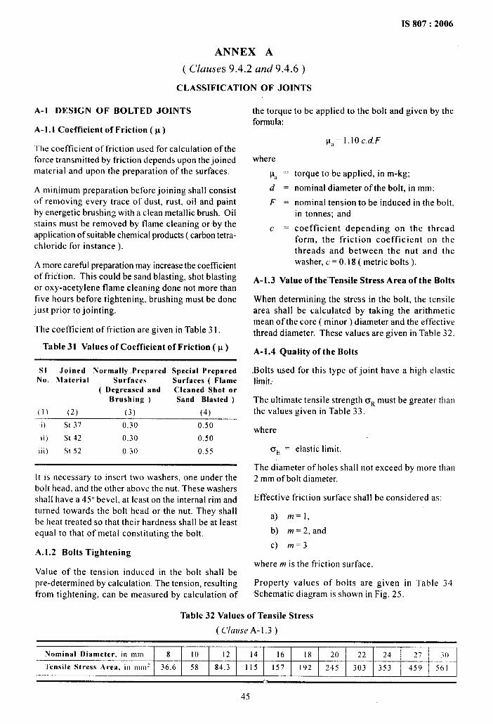
IS 807:2006
ANNEX A
( Clauses 9.4.2 and 9.4.6)
CLASSIFICATION OF JOINTS
A-1 DESIGN OF BOLTED JOINTS
A-1.l Coefficient of Friction ( p )
The coefficient of friction used for calculation of theforce transmitted by friction depends upon the joinedmaterial and upon the preparation of the surfaces.
A minimum preparation before joining shall consistof removing every trace of dust, rust, oil and paintby energetic brushing with a clean metallic brush. Oilstains must be removed by tlame cleaning orby theapplication of suitable chemical products ( carbon tetra-chloride for instance ).
A more careful preparation may increase the coefficientof friction. This could be sand blasting, shot blastingor oxy-acetylene flame cleaning done not more thanfive hours before tightening, brushing must be donejust prior to jointing.
The coefficient of friction are given in Table31.
Table 31 Values of Coefficient of Friction(p)
SI Joined Normally Prepared Special PreparedNo. Material Surfaces Surfaces ( Flame
( DegreasesI and Cleaned Shot orBrushing ) Sand Blasted )
(1) (2) (3) (4)
i) St 37 0.30 0.50
ii) St 42 0.30 0.50
Iii) St 52 0,30 0.55
It is necessary to insert two washers, one under thebolt head, and the other above the nut. These washersshall have a 45° bevel, at least on the internal rim andturned towards the bolt head or the nut. They shallbe heat treated so that their hardness shall be at leastequal to that of metal constituting the bolt.
A.1.2 Bolts Tightening
Value of the tension induced in the bolt shall bepre-determined by calculation. The tension, resultingfrom tightening, can be measured by calculation of
the torqueformula:
where
P, =d=
F=
c=
to be applied to the bolt and given by the
p,=l.lOc. d.F
torque to be applied, in m-kg;
nominal diameter of the bolt, in mm;
nominal tension to be induced in the bolt,in tonnes; and
coefficient depending on the threadform, the friction co~fficient on thethreads and between the nut and thewasher, c = 0.18 ( metric bolts ).
A-1.3 Value of the-Tensile Stress Area of the Bolts
When determining the stress in the bolt, the tensilearea shall be calculated by taking the arithmeticmean of the core ( minor ) diameter and the effectivethread diameter. These values are given in Table 32.
A-1.4 Quality of the Bolts
-Bolts used for this type of joint have a high elasticlimit:
The ultimate tensile strength ORmust be greater thanthe values given in Table 33.
where
‘E = elastic limit.
The diameter of holes shall not exceed by more than2 mm of bolt diameter.
Effective friction surface shall be considered as:
a) m=l,
b) m=2, and
c) m=3
where m is the friction surface.
Property values of bolts are given in Table 34.Schematic diagram is shown in Fig. 25.
Table 32 Values of Tensile Stress
( Clause A-1.3)
~ Nominal Diameter. in mmL
8 10 12 14 16 18 20 22 24 27
J
.30
i Tensile ‘Stress Area, in inn): 36.6 58 84.3 115 157 192 245[
303 353 459 501
45
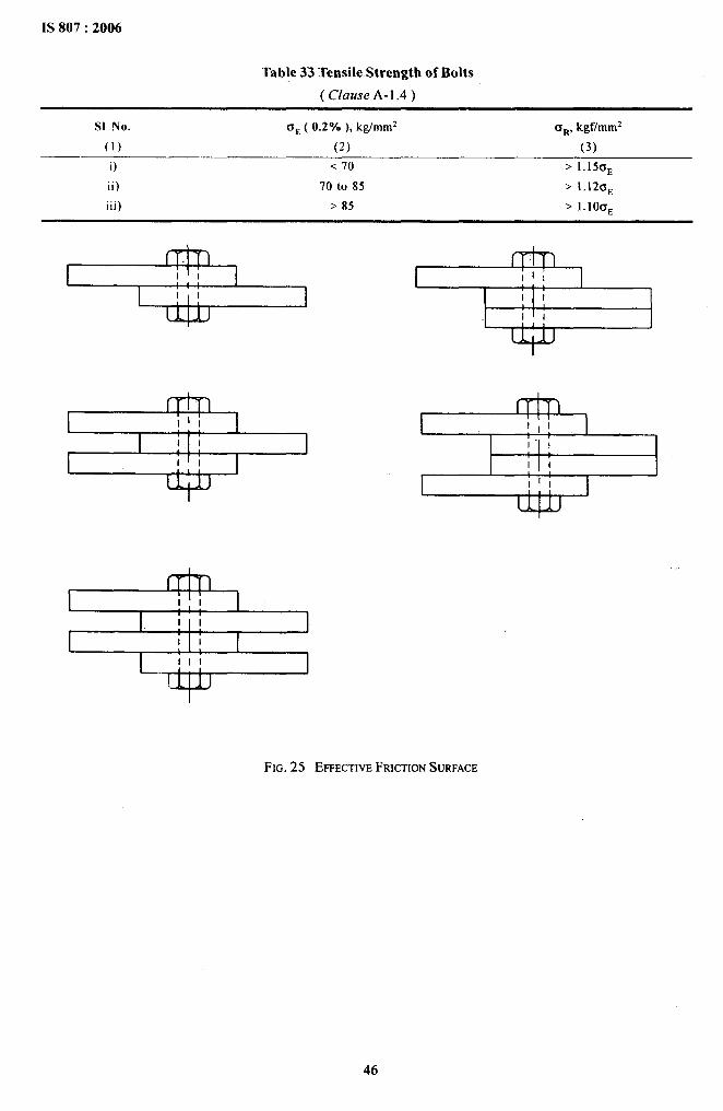
.
Table 33 Tensile Strength of Bolts
( Clause A- 1.4 )
SI No. o~ ( 0.2”/. ), kg/mm2 a~, kgf/mm2
(1) (2) (3)
i) <70 ~ 1.15tJE
ii) 70 to 85 > 1.12f3E
iii) >85 > I. IOCTE
1
I1
1:1 1
I IllI
I I I II Ill
I
I 1I1111 II I
I Iili# 1 1 1
FIG.25 EFFECTIVEFRICTIONSURFACE
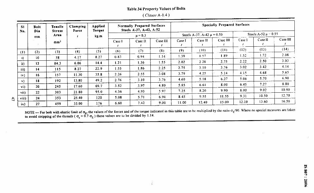
.
Table 34 Property Values of Bolts
( Clause A-1.4)
SI Bolt Tensile Clamping Applied Normally Prepared Surfaces Specially Prepared SurfacesNo. Dia Stress Force Torque Steels A-37, A-42, A-52
mm Area t kg.m p=o.3 Steels A-37. A-42 p = 0.50 Steels A-52 p = 0.55
mmz Case I Case 11 Case 111 Case I Case 11 Case 111 Case 1 Case 11 Case 111t t t t t t t t t
(1) (2) (3) (4) (5) (6) (7) (8) (9) (lo) (11) (12) (13) (14)
i) 10 58 4.17 8.27 0.83 0.94 1.14 1.39 1.j7 1.89 [.52 1.72 2.08
ii) 12 84.3 6.06 14.4 1.21 1.36 1.55 2.02 2.28 2.75 2.22 2.50 3.03
iii) 14 115 8.27 22.9 1,55 1.86 2.25 2.75 3.10 3.76 3.02 3.42 4.14
iv) 16 157 11.30 35.8 2.26 2,55 3.08 3.79 4.25 5.14 4.15 4.68 j.65
v) 18 192 13.80 49.2 2.76 3.10 3.76 4.60 5.18 6.27 5.06 5.70 6.90
vi) 20 245 17.60 69.7 3.52 3.97 4.80 5.85 6.61 8.00 6.45 7.27 8.80
vii) 22 303 21.80 95.0 4.36 4.93 5.97 7.25 8.20 9.90 8,00 9.02 10.90
A viii) 24 353 25.40 120 5.08 5.71 6.94 8.45 9.55 11.55 9.31 10.50 12.70+ix) 27 459 33.00 176 6.60 7.42 9.00 11.00 12.40 15.00 12.10 13.60 16,50
NOTE — For bolt with elastic limit of CE, the values of the forces and of the torque indicated in this table are to be multiplied by the ratio oE/90. Where no special measures are takentoavoid stripping of thethreads [O, =0.76E) these values aretobe divided bY 1.14.
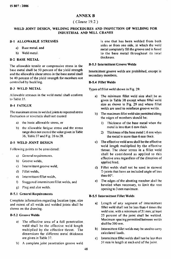
1S 807:2006
ANNEX B
( clause 19.2)
WELD JOINT DESIGN, WELDING PROCEDURES AND INSPECTION OF WELDING FORINDUSTRIAL AND MILL CRANES
B-1 ALLOWABLE STRESSES
a) Base metal, and
b) Weld metal.
B-2 BASE METAL
The allowable tensile or compressive stress in thebase metal shall be 50 percent of the yield strengthand the allowable shear stress in the base metal shallbe 40 percent of the yield strength for members notcontrolled by buckling.
B-3 WELD METAL
Allowable stresses in the weld metal shall conformm Table 35.
B-4 FATIGUE
The maximum stress in welded joints to repeated stressfluctuation or reversals shall not exceed
a) the basic allowable stress, or
b) the allowable fatigue stress and the stressrange does not exceed the value given in Table36, Table 37 and Fig. 26to 28.
B-5 WELD JOINT DESIGN
Following points to be considered:
a) General requirements,
b) Groove welds,
c) Intermittent groove weld,
d) Fillet welds,
ej Intermittent fi!let welds,
f) Staggered intermittent fillet welds, and
g) Plug and.slot welds.
B-5. I Genera} Requirements
Complete information regarding location type, sizeand extent of all welds and welded joints shall beshown on the drawing.
B-5.2 Groove Welds
a) The effective area of a full penetrationweld shall be the effective weld lengthmultiplied by the effective throat. Thedimensions for different metal thicknessare given in Table 37.
b) A complete-joint penetration groove weld
is one that has been welded from bothsides or from one side, in which the weldmetal completely fill the groove and is fusedto the base metal throughout its totalthickness.
B-5.3 Intermittent Groove Welds
Intermittent groove welds are prohibited, except insecondary members.
B-5.4 Fillet Welds
Types of fillet weld shown in Fig. 29.
a)
b)
c)
d)
e)
The minimum fillet weld size -shallabe asgiven in Table 38 except where fillet weldsize as shown in Fig. 29 and where filletwelds are used to reinforce groove welds.
The maximum fillet weldsizepermitted alongthe edges of members should be:
1) Thickness of the base metal when themetal is less than 6 mm thick.
2) Thickness of the base metal 1.6 mm whenthe metal is more than 6 mm thick.
The effective weld area shallbe the effectiveweld length multiplied by the effectivethroat. The shear stress in a fillet weldshall be considered as applied to thiseffective area regardless of the direction ofapplied load.
Fillet welds shall not be used in skewedT-joints that have an included angle of lessthan 60”0.
The edges of the abutting member shall bebeveled when necessary, to limit the rootopening to 3 mm maximum.
B-5.5 Intermittent Fillet Welds
a)
b)
c)
Length of any segment of intermittentfillet weld shall not be less than 4 times theweld size, with a minimum of 51 mm; at least25 percent of the joint shall be welded.Maximum spacing permitted between weldsshall be 300 mm.
Intermittent fillet welds may be used to carrycalculated loads.
Intermittent fillet -weldsshall not be less than51 mm in length at each end of the joint.
48
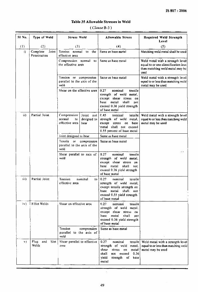
IS 807:2006
Table 35 Allowable Stresses in Weld
( Clause B-3)
.II No. Type of Weld Stress Weld Allowable Stress Required Weld Strength
Level
,(1) (2) (3) (4) (5)
i) Complete Joint Tension normal to the Same as base metal Matching weld metal shall be usedPenetration effective area
Compression normal to Same as base metal Weld metal with a strength levelthe effective area equal to or one classification less
than matching weld metal may beused
Tension or compression Same as base metal Weld metal with a strength levelparallel to the axis of the equal to or less than matching weldweld metal may be used
Shear on the effective area 0.27 nominal tensilestrength of weld metal,except shear stress onbase metal shall notexceed 0.36 yield strengthof base metal
ii) Partial Joint Compression Joint not C.45 nominal tensile Weld metal with a strength levelnormal to designed to strength of weld metal, equal to or less than matching weldeffective area bear except stress on base metal may be used
“meta[ sha!l not exceed0.55 percent of base metal
.loint designed to bear Same as base metal
Tensile or compression Same as base metalparallel to the axis of theweld
Shear parallel to axis of 0.27..
nominal tensileweld strength of weld metal,
except shear stress onbase metal shall notexceed 0.36 yield strengthof base metal
iii) Partial Joint Tension nominal to 0.27 nominal tensileeffective area strength of weld metal,
except tensile strength onbase metal shall notexceed 0.55 yield strengthof base metal
iv) Fillet Welds Shear on effective area 0.27 nominal tensilestrength of weld metal,except shear stress onbase metal shall notexceed 0.36 yield strengthof base metal
Tension compression Same as base metalparallel to the axis ofweld
v) Plug and Slot Shear parallel to effective 0.27 nominal tensil e Weld metal with a strength levelWelds area strength of weld metal, equal to or less than matching weld
shear stress on metal metal may be usedshall not exceed 0.3 6yield strength of bas emetal
49

.
IS 807:2006
Table 36 Fatigue Stress Provisions — Tension or Reversal Stresses
( Clause B-4)
S1 No. General Condition Situation Stress Category
(1) (2) (3) (4)
O
ii)
Plain Material
Built-up Members
iii) Groove Welds
iv)
v)
vi)
vii)
Groove Welded
Groove Welds
Groove or FilletWelded Connection
Fillet WeldedConnections
viii) Fillet Welds
ix)
x)
Stud Welds
Plug and Slot Welds
Base metal with rolled or cleaned surfaces. Oxygen cut edgeswith tine smoothness
Base metal and weld met-al in members without attachment,built-up plates or shapes connected by continuous complete orpartial joint penetration groove welds or by continuous fiIletwelds parallel to the direction of applied stress
Calculated flexural stress at toe of transverse stiffener welds ongirder web or flanges
Base metal at end or partial length welded cover mates havingsquare or tapered endswith or without welds across the ends
Base metal and weld metal at complete joint penetration groovewelded splices of rolled and welded sections having similarprofiles when welds are ground and weld soundness establishedby non destructive testing
Base metal and weld metal in or adjacent to complete jointpenetration groove welded splices at transitions in width orthickness with welds ground to provide slopes no steeper than 1to 2 % and weld soundness established by non-destructive testing
Base metai at details of any length attached by groove weldssubjected to transverse or longitudinal loading or both whenweld soundness is transverse to the direction of stress isestablished by non-destructive testing and the detail embodiesa transition radius, R with weld termination ground when
a) R>610mmb)610mm>R> 152mmc)152mm>R>51mmd)51mm~R>0
Base metal, and weld metal in or adjacent complete jointpenetration groove welded splices either not requiring transitionor when metal required with transition having slope not greaterthan I to 2 % and when in either case. reinforcement is notremoved and weld soundness is established by non-destructivetesting
Base metal at details attached by groove or fillet welds subjectto longitudinal loading where the details embodied a transitionradius R, less than 51 mm and when the detail length L, parallelto the line of stress isa) <51 mmb)51mm<L<102mmc) L > 102 mm
Base metal at details attached by fillet welds parallel to thedirection of stress regardless of length when the details embodiesat transition radius R, 5 I mm or greater and with weld terminationgrounda) when R >610 mmb)when610mm>R> 152mmc)when152mm>R>51mm
Shear stress on throat of fillet welds
Base metal at intermittent welds attaching transverse stiffenersand stud type shear connectors
Base metal at intermittent fillet welds attaching longitudinal stiffeners
Shear stress on nominal shear area of stud type shear connectors
Base metal adjacent to or connected by plug or slot welds
A
B
c
E
B
B
Longitudinalloading materialshaving equal orunequal thicknesssloped weldsground webconnedion
BBccDDEE
c
cDE
BcD
F
c
E
F
E
50

—.——-.._ ———________
2000
1507)
1000
500
-1
500
1000
1500
2000
1S-807 :.2006
200
150
100
50
-50
-1oo
-150
-200
FIG. .26 ALLOWABLEFATIGUESTRESS FOR CRANES ( M 1 and M2 )
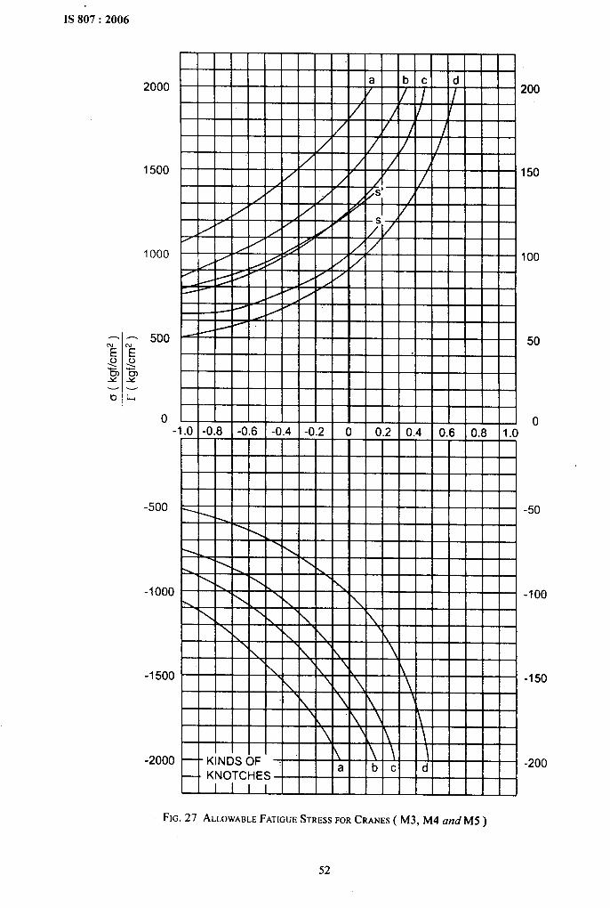
IS 807:2006
2000
1500
1000
-1=
o
-500
-1000
-1500
-2000
I I WI I I 1
I I 1 I III I I I I I I I
I i II
I I I I I I I I I I I I I I I I I I 1 I I
200
150
100
50
0
-50
-1oo
-150
-200
FIG. 27 ALLOWABLEFATIGUESTRESSFORCRANES ( M3, M4 and M5 )
52
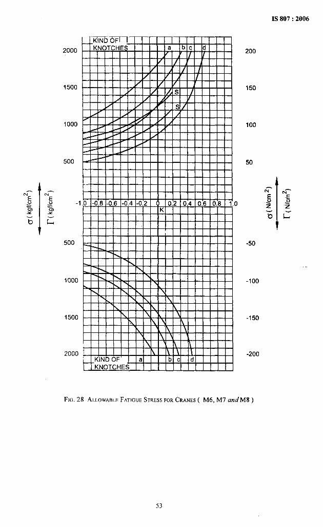
IS 807:2006
2000
1500
1000
500
-1
500
1000
1500
2000
o
200
150
100
50
-50
-1oo
-150
-200
,.
FIG. 28 ALLOWABLEFATIGUESTRESS FOR CRANES ( M6, M7 and M8 )
53
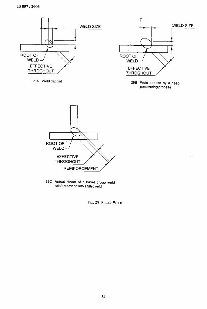
1S 807:2006
—
WELD SIZE- --Jd
f(- ?‘.,,
I iROOT OF
WELD
29A Weld deposit
1 ik’N\ 1ROOT OF
WELD
EFFECTIVETHROGHOUT
REINFORCEMENT /
29C Actual throat of a bevel group weldreinforcement with a fillet weld
—
-WELDSIZE
-; ; ~
--
ROOT CFWELD
29B Weld deposit by a deeppenetrating process
FIG.29 FILLET WELD
54
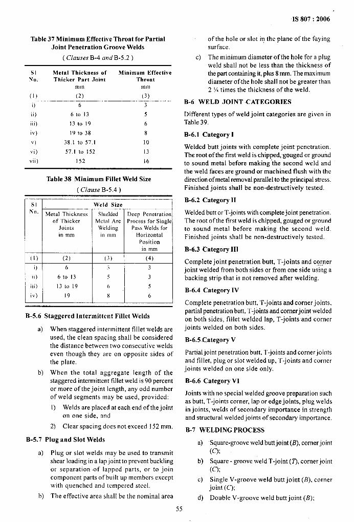
IS 807:2006
Table 37 Minimum Effective Throat for PartialJoint Penetration Groove Welds
( Clauses B-4 and B-5.2)
SI Metal Thickness of Minimum EffectiveNo. Thicker Part Joimt Throat
mm mm
(1) (2) (3)
O 6 3
ii) 6to !3 5
iii) 13to19 6
iv) 19 to 38 8
v) 38.1 to 57.1 10
vi) 57,1 to 152 13
vii) 152 16
Table 38 Minimum Fillet Weld Size
( Clause B-5.4)
““~ Metal Arc Process for Single
in mm in mm HorizontalPositionin mm
(1) I (2) I (3) I (4) I
EM!_U-lB-5.6 Staggered Intermittent Fillet Welds
a) When staggered intermittent fillet welds areused, the clean spacing shall be consideredthe distance between two consecutive weldseven though they are on opposite sides ofthe pIate.
b) When the total aggregate length of thestaggered intermittent fillet weld is 90 percentor more of the joint length, any odd numberof weld segments may be used, provided:
1) Welds are placed at each end of the jointon one side, and
2) Clear spacing does not exceed 152 mm.
B-5.7 Plug and Slot Welds
a)
b)
Plug or slot welds may be used to transmitshear loading in a lapjoint to prevent bucklingor separation of lapped parts, or to joincomponent parts of built up members exceptwith quenched and tempered steel.
The effective area shall be the nominal area
55
of the hole or slot m the plane of the fayingsurface.
c) The minimum diameter of the hole for a plugweld shall not be less than the thickness ofthe part containing it, plus 8 mm. The maximumdiameter of the hole shall not be greater than2 Mtimes the thickness of the weld.
B-6 WELD JOINT -CATEGORIES
Different types of weld joint categories are given inTable 39.
B-6.1 Category I
Welded butt joints with complete joint penetration.The root of the first weld is chipped, gouged or groundto sound metal before making ‘the second weld andthe weld faces are ground or machined flush with thedirection of metal removal parallel to the principal stress.Finished joints shall be non-destructively tested.
B-6.2 Category 11
Welded butt or T-joints with complete joint penetration.The root of the first weld is chipped, gouged or groundto sound metal before making the second weld.
Finished joints shall be non-destructively tested.
B-6.3 Category 111
Complete joint penetration butt, T-joints and cornerjoint welded from both sides or from one side using abacking strip that is not removed after welding.
B-6.4 Category IV
Complete penetration butt, T-joints and corner joints,partial penetration butt, T-joints and comer joint weldedon both sides, fillet welded lap, T-joints and cornerjoints welded on both sides.
B-6.5 -Category V
Partial joint penetration butt, T-joints and corner jointsand fillet, plug or slot welded up, T-joints and cornerjoints welded on one side only.
B-6.6 Category VI
Joints with no special welded groove preparation suchas butt, T-joints corner, lap or edge joints, plug weldsin joints, welds of secondary importance in strengthand structural welded joints of secondary importance,
B-7 WELDING-PROCESS
a)
b)
c)
d)
Square-groove weld butt joint (B), comer joint
(Q;Square - groove weld T-joint (7’),corner joint(q;
Single V-groove weld butt joint (B), corner
joint (C);
Double V-groove weld butt joint (B);
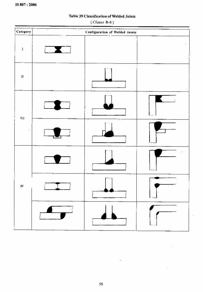
.
Table 39 Classification of Welded Joinls
( Clause B-6)
Category Conf’iguratlon of Welded Joints
II
r
11
&
- A FIII
,- * F
EL F
N
= A F
e A E
56

IS 807:2006
Table 39 — Continued
.
NOTES
1 Details of weld joint (groove design, root opening, etc) are those required for the welding process to be used.
2 The diameters of plug welds or the width of slot welds is indicated by dimension ‘d’.
e)
9
g)
h)
Single-bevel groove weld butt joint (B); joint (C);
Single-bevel groove weld T-joint (7), comer j) Single J-groove weld butt joint (B), T-jointjoint (C); (7’),corner joint (C); and
Double -bevel groove weld butt joint T-joint, k) Double J-groove weld T-joint(7), corner jointcomer joint (C); (C), butt joint (B).
Single U-groove welds butt joint (B), corner Some of various joints are given in Table 40.
57
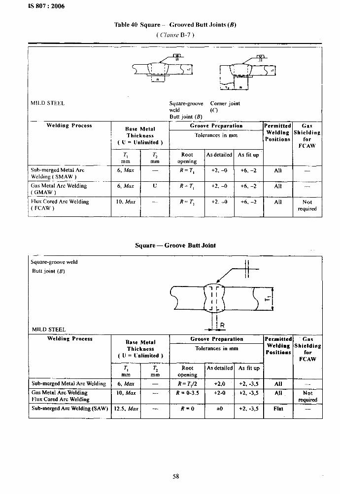
&
IS ?307:2006
Table 40 Square — Grooved Butt Joints (B)
( Clause B-7)
.
MILD STEEL Square-groove Corner jointweld (f)Butt joint (f?)
Welding ProcessBase Metal
Groove Preparation Permitted Gas
Thickness Tolerances in mm Welding Shielding
( U = Unlimited )Positions for
FCAW
T, Tz Root As detailed As tit Upmm mm opening
$ub-merged Metal Arc 6, Max — R=TI +2, –0 +6, –2 All —Welding ( SMAW )
Gas Metal Arc Welding 6, Max u R=T1 +2, –(J +6, –2 All —GMAW )
Flux Cored Arc Welding 10, Max — R=TI +2, –(J +6, –2 All Not: FCAW ) required
Square — Groove Butt Joint
Square-groove weld 1
Butt joint (B)II
&
b-
1MILD STEEL
Welding ProcessBase Metal
Groove Preparation Permitted Gas
Thickness Tolerances in mm Welding Shielding
( U = Unlimited )Positions for
FCAW
T] Tz Root As detailed As tit Up
mm mm opening
Sub-merged Metal Arc Welding 6, Max — R= T112 +2,0 +2, -3,5 All —
Gas Metal Arc Welding 10, Max — R = 0-3.5 +2-0 +2, -3,5 All NotFlux Cored Arc Welding required
Sub-merged Arc Welding (SAW) 12.5, Max — R=O +0 +2, -3,5 Fiat —
58
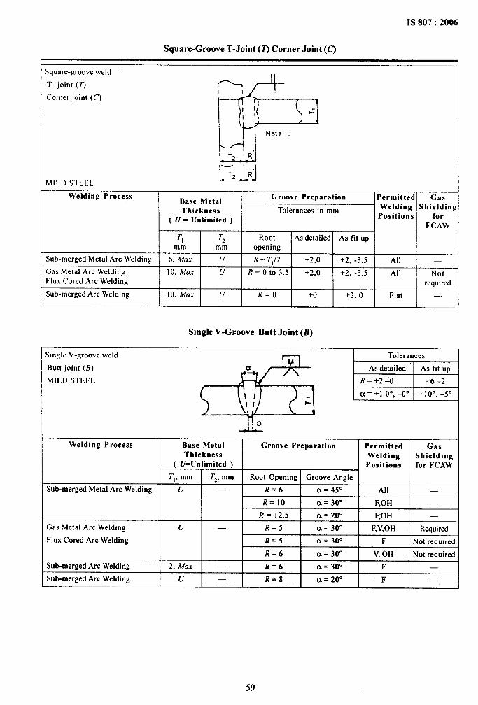
1S 807:2006
.
Square-Groove T-Joint (7) Corner Joint (C)
Square-groove weld
T- joint (T)I I
Corner joint (C)
MILD STEEL—-
Welding ProcessBase Metal
Groove Preparation Permitted Gas
Thickness Tolerances in mm Welding Shielding
( U = Unlimited )Positions for
FCAW
TI Tz Root As detailed As fit Upmm mm opening
Sub-merged Metal Arc Welding 6, &tOX u R= T,12 +2,0 +2, .3,5 All
Gas Metal Arc Welding IO, Max u R= Oto 3.5 +2,0 +2, -3,5 All NotFlux Cored Arc Welding required
Sub-merged Arc Welding 10, Max u R=O *O +2, () Flat
Single V-Groove Butt Joint (B)
Single V-groove weld
AA
Tolerances
Butt joint (B) As detailed As fit UP
MILD STEEL df%-J \.! J \ i
!Q-d&-
Welding Process Base Metal Groove PreparationThickness
( U=Unlimited )
T,, mm T2,mm Root Opening Groove Angie
Sub-merged Metal Arc Welding u — R=6 ~ = 45o
R=1O ~ = 300
R= 12.5 ~ = 200
Gas Metal Arc Welding u — R=5 ~ = 300
Flux Cored Arc Welding R=5 ~ = 300
R=6 ~ = 300
Sub-merged Arc We[ding 2, Max — R=6 ~ = 300
Sub-merged Arc Welding u — R=8 (-J= 200
All l–
*
59
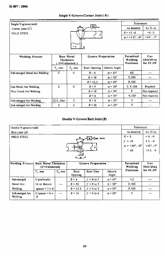
IS 807:2006
Single V-Groove Corner Joint ( B )
Not recruired
$iogle V-groove weld
Corner joint (C)
MILD STEEL,
I 17- L 1
Welding Process Base Metal Groove Preparation PermittedThickaess Welding
( U= Unlimited ) Positions
T,, mm T,, mm Root Opening Groove Angle
GasShieldingfor FCAW
—;ub-merged Metal Arc Welding u u R=6 a = 45° All
R=1O a = 3130 F, OH
R= 12.5 a = 20° F, OH
u R=5 a= 30° F, V, OH
—
Requiredlas Metal Arc Welding
‘Iux Cored Arc-Welding
uNot required
;ub-merged Arc We!ding
lub-merged Arc Welding
12.5, &fL7X
uI
— I
Double V-Groove Butt Joint (B)
Double V-groove weld
Butt ioint (B)
Tolerances
As fii ~Ip
= 6.-0
1.5. –o
+10”, –5”
+1.5, –o
As detailed
MILD STEEL
@
fa M “
.,l“-
J@
R=O
f=io
a = +19° –0°
= +0
Permitted
Note
Welding Process Base Metal Thickness I Groove Preparation ‘ Gas(f/= Unlimited)
T,, mm I T,, mm Root Root Face GrooveOpening Angle
Sub-merged
Metal Arc
Weldirw
U preferably
16 or thicker
svacer = 3 x R -~
F,(3H I —F. OH l–
Sub-merged ArcWelding
U spacer = 6 x —R
R=16 f= Oto6 I a = 20” Fl -
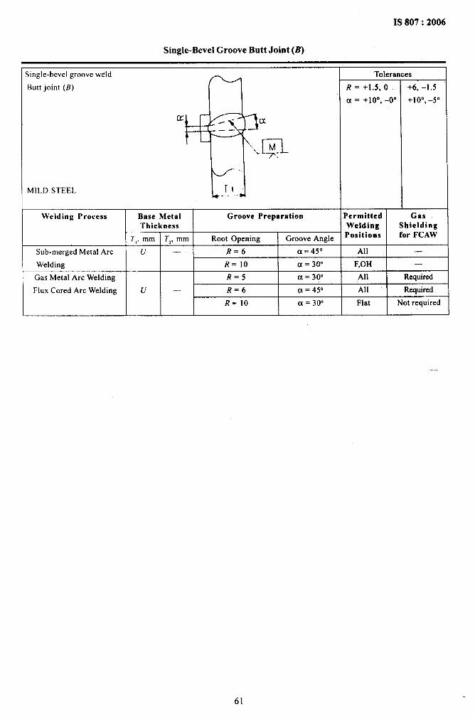
. . —
.
IS 807:2006
Single-Bevel Groove Butt Joint (B)
lingle-bevel groove weld
9 “ I
Tolerances
Butt joint (B) R=+l.5,0 +6, -1.5
~ = +100 -00 +10”, -5”
IY --1
(x.. --—---
.
~,n\M~ _p..
<.
MILD STEEL T1. .
Welding Process Base Metal Groove Preparation Permitted GasThickness Welding Shielding
7[, mm Tz, mm Root Opening Groove Angle ‘ositions for FCAW
Sub-merged Metal Arc u — R=6 ~=450 All —
Welding R=IO ~ = 30. F,OH —
Gas Metal Arc Welding R=5 a = 30. All Required
Flux Cored Arc Welding u — R=6 @= 45. All Requirwd
R=1O ~ = 30. Flat Not required
,,,
61
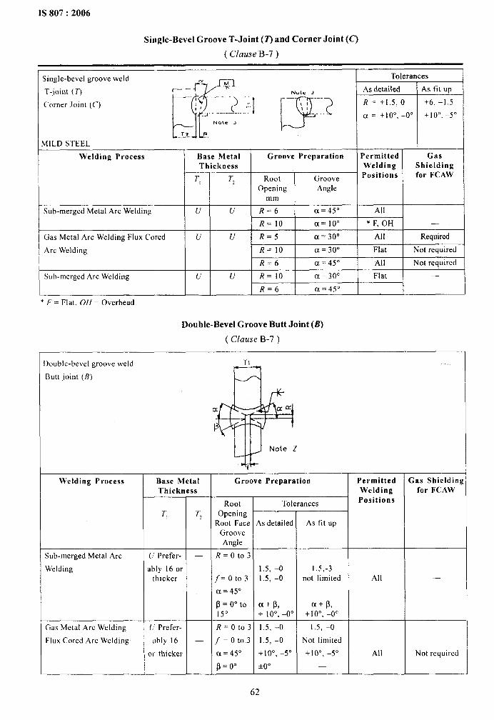
Single-Bevel Groove T-Joint (T) and Corner Joint (C’)
( Clause B-7)
.Single-bevel groove weld
v
f“..~x
T-joint (T)-..
L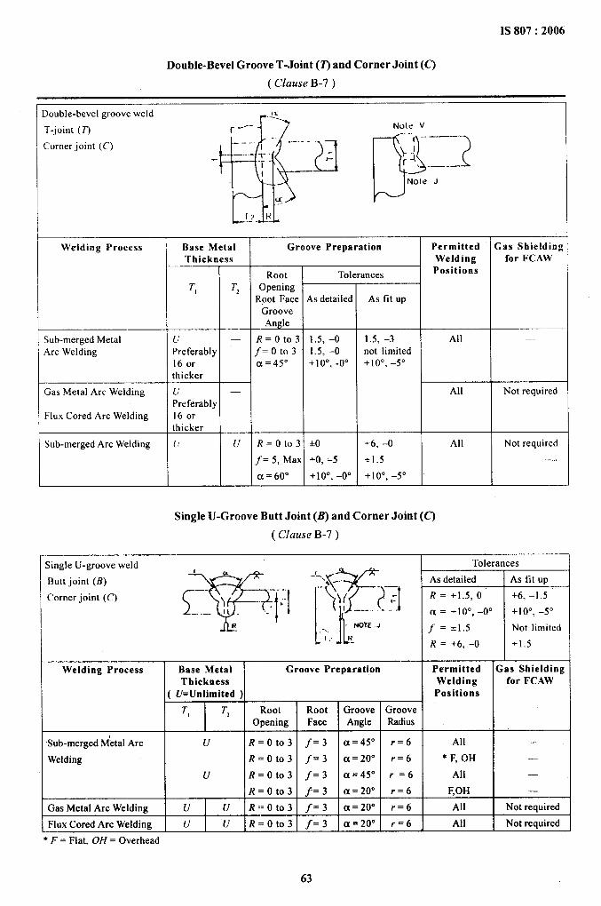
—
IS 807:2006
.
Double-Bevel Groove T-Joint (2) and Corner Joint (C)
( Clause B-7)
)ouble-bevel groove weld
T-joint (T)
Corner joint (C)
Welding Process
Sub-merged MetalArc Welding
Gas Metal Arc Welding
Flux Cored Arc Welding
Sub-merged Arc Welding
, /- J+.,Note V-.—.
~1,.——..’.
}J~4 i?
Note J
Base MetalThickness
T, I T,
1uPreferably16 orthicker
lJ —
Preferably16 orthicker
OpeningRoot Face
GrooveAngle
R= Oto3f=oto3~=450
As detailed
1.5, –o1.5, -o+10”. .00
TR= Oto3 *O
f= 5, Max +0, -5
~ = fjoo +10”, –0”
TAs tit up
1.5, -3 Allnot limited+10”, –5”
I All
+(j, -(l All
*1.5
+10”, –5”
Single U-Groove Butt Joint (B) and Corner Joint (C)
( Clause B-7)
Gas Shieldingfor FCAW
Not required
Not required
.,, ,
Single U-groove weld
Butt joint (B)
Corner joint (C)
Tolerances(
As detailed
ly~~~l -’:’qg{:,
As fit Up
h
R = +1.5, O +6, –1 .5
a = +10”, –0” +10”, –5”
R NOTE J. -., f =*1.5 Not limited,. ,{.. R = +6, -0 +1.5
Welding Process Base Metal Groove Preparation Permitted Gas ShieldingTlrickness Welding for FCAW
( U=Unlimited ) Positions
T, T, Root Root Groove GrooveOpening Face Angle Radius
Sub-merged M’etal Arc u R= Oto3 f= 3 ~ = 450 ~=(j All .
Welding R= Oto3 j= 3 ~ = 200 ~=6 * F, OH .
u R= Oto3 f= 3 ~ = 450 ~=6 All —
R= Oto3 f= 3 a = 20° ~=6 F,OH —
Gas Metal Arc Welding u u R= Oto3 f= 3 a = 20° ~=6 All Not required
Flux Cored Arc Welding u u R= Oto3 f= 3 u = 200 ~=6 All Not required
* F = Flat, OH = Overhead
63
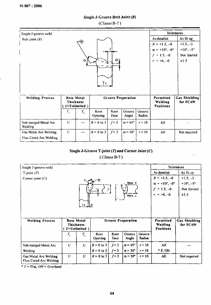
IS 807:2006
Single J-Groove Butt Joint (B)
(Clause B-7 )
.jingle J-groove weld
Butt joint (B)
Welding Process
Sub-merged Metal ArcWelding
Gas Metal Arc Welding
Flux Cored Arc Welding
Base Metal Groove PreparationThickness
( U=Unlimited )
I I i I I
;ingle J-groove weld
T-joint (T)
Corner joint (C)
Tolerances
, I +10°,-50~ = +100 –00
f = 1.5,–0 I Not limited
r = +fj, –() *1.5
Permitted Gas ShieldingWelding for FCAWPositions
ru-\ -“F
.—~fp”.—-.ifI ___ *-
--- ..I
Sub-merged Metal Arc
Welding
+1
Single J-Groove T-joint (T) and Corner Joint (C’)
( Clause B-7)
Ldk
..... Nolo V
1!?.
‘)“;~--+.,.
Welding Process
Gas Metal Arc WeldingFlux Cored Arc Welding
Base MetalThickness
( U=Unlimited )
-=-b-
Groove Preparation
R= Oto3 f= 3 a = 30° r=10
u u R= Oto3 f= 3 a = 30” r=10
Tolerar
As detailed
R = +1.5, -O
a = +1 O”, -0°
f = 1.5, -0
r= +6,-O
PermittedWeldingPositions
All
* F, OH
All
es
As fit Up
+1.5, -3
+10”, -5”
Not limited
*1.5
Gas Shieldingfor FCAW
.
Not required
* F = Flat, OH = Overhead
64
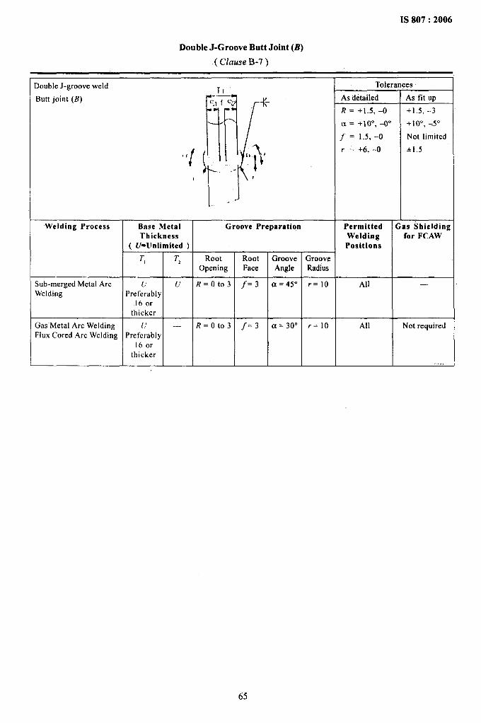
. . . . .. . .. . . . .
.
IS 807:2006
Double J-Groove Butt Joint (B)
( Clause B-7)
Double J-groove weld
Butt joint (B)
i
I
<-;> K. -.
[I’/\,,”’1,
... pI
. .
-Welding Process
Sub-merged Metal ArcWelding
Gas-Metal Arc WeldingFlux Cored Arc Welding
Base Metal I Groove PreparationThickness
( U= Unlimited )
T, T, RootOpening
u u R= Oto3Preferably
160rthicker
11 — R= Oto3Preferably
16 orthicker
RootFace
j-= 3
f= 3
GrooveAngle
a = 30°
trooveRadius
r=10
r=10
Toleral
As detailed
R = +1.5, -O
a = +10”, -00
f = 1.5, -o
r = +6. -O
PermittedWeldingPositiona
All
All
As fit UP
+1.5, -3
+10”, –5”
Not limited
*1.5
Gas Shieldingfor FCAW
—
Not required
65
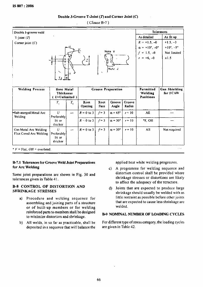
IS 807:2006
Double J-Groove T-Joint (.2’)and Corner Joint (C)
( Clause B-7)
Double J-groove weld
T-joint (T)
Corner joint (C)
r:%
dl--
Note V
““R~..—.——.+
t
..—Nole, J
..
Welding Process
w
I T,
I
T,
Sub-merged Metal Arc u —Welding Preferably
160rthicker
Gas Metal Arc Welding u —Flux Cored Arc Welding Preferably
16 orthicker
● F = Flat, OH = overhead.
Groove Preparation
Root Root Groove GrooveOpening Face Angle Radius
R= Oto3 f= 3 ~ = 45° r=10
R= Oto3 j= 3 a = 30” r=10
R= Oto3 f= 3 ~ = 3rJo r=10
Tolera
As detailed
R = +1,5, -O
~ = +100 -00
f = 1.5, -0
r = +6, –o
es
As tit Up
+1.5, -3
+10”, -5”
Not limited
+1.5
Permitted Gas Shielding‘Welding for FCAWPositions
All Not required
I
B-7.1 Tolerances for Groove Weld Joint Preparationsfor Arc Welding
Some joint preparations are shown in Fig. 30 andtolerances given in Table41.
B-8 CONT-ROL OF DISTORTION ANDSHRINKAGE STRESSES
a) Procedure and welding sequence forassembling and joining parts of a structureor of built-up members or for weldingreinforced parts to members shall be designedto minimize distortion and shrinkage.
b) All welds, in so far as practicable, shall bedeposited in a sequence that will balance the
c)
d)
applied heat while welding progresses.
A programme for welding sequence anddistortion control shall be provided whereshrinkage stresses or distortions are Iikelyto affect the adequacy of the structure.
Joints that are expected to produce largeshrinkage should &ually be welded with aslittle restraint as possible before other jointsthat are expected to cause less shrinkage arewelded.
B9 NOMINAL NUMBER OF MM.DING CYCLES
For different type of stress category, the loading cyclesare given in Table 42.
66
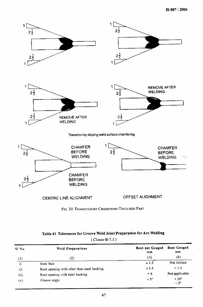
IS 807:2006
1
I
1
24
I
24
1
1 REMOVE AFTER
2;
24
1
Transition byslopingweldsurface chamfering
1 CHAMFER 1CHAMFER
24 BEFORE 24 BEFOREWELDING ~
1
24 BEFORE
1 WELDING
CENTRE LINE ALIGNMENT OFFSET ALIGNMENT
FIG. 30 TRANSITIONBY CHAMFERINGTHICKNESSPART
Table 41 Tolerances for Groove Weld Joint Preparation for Arc Welding
( Clause B-7.1)
S1 No. Weld Preparations Root not Gouged Root Gougedmm mm
(1) (2) (3) (4)
i) Root face *1.5 Not limited
ii) Root opening with other than steel backing +1.5 +1.5
iii) Root opening with steel backing +6 Not applicable
iv) Groove angle + 5“ + 10”-5°
67
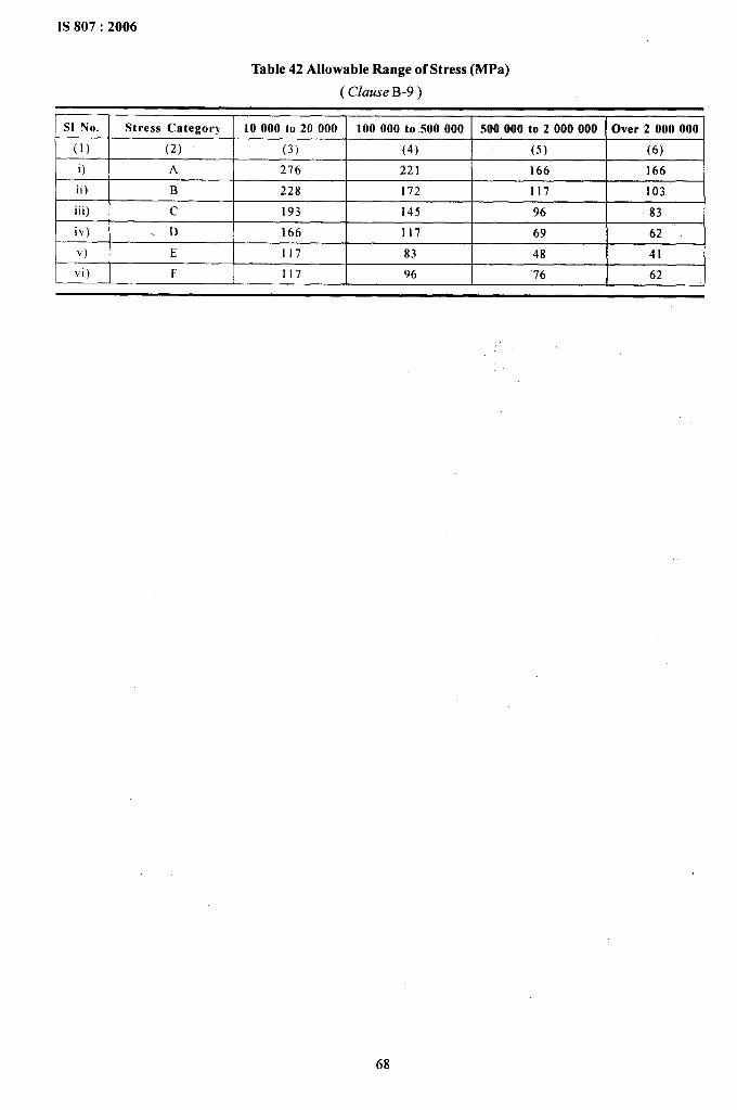
IS 807:2006
Table 42 Allowable Range of Stress (MPa)
( Clause B-9)
SI No. Stress Category 10000 to 20000 100000 to .500.000 500000 to 2000000 Over 2000000
(1) (2) (3) (4) (5) (6)
i) A 276 221 166 166
ii) B 228 172 117 103
iii) c 193 145 96 83
iv) . D 166 117 69 62
v) E 117 83 48 41
vi) F 117 96 76 62
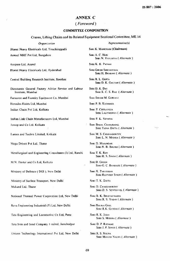
——_—— ..—-. ——... .
IS 807:2006
ANNEX C
( Foreword)
COMMI’ITEE COMPOSITION
Cranes, Lifting Chains and Its Related Equipment Sectional Committee, ME 14
Organization
Bharat Heavy Electrical Ltd, Tiruchirappalli
Armsel MHE Pvt Ltd, Bangalore
Anupam Ltd, Anand
Bharat Heavy Electrical Ltd, Hyderabad
Central Building Research Institute, Roorkee
Directorate General Factory Advice Service and LabourInstitute. Mumbai
Furnance and Foundry Equipment Co, Mumbai
Hercules Hoists Ltd, Mumbai
Indian Chain Pvt Ltd, Kolkata
Indian Link Chain Manufacturers Ltd, Mumbai
.lessop and Co Ltd. Kolkata
Larsen and Toubro Limited, Kolkata
Mega Drives Pvt Ltd, Thane
Metallurgical and Engineering Consultants (1) Ltd, Ranchi
M.N. Dastur and Co Ltd, Kolkata
Ministry of Defence ( DGI ), New Delhi
Ministry of Surface Transport. New Delhi
Mukand Ltd. Thane
National Thermal Power Corporation Ltd, New Delhi
Reva Engineering industrial (P) Ltd. New Delhi
Tata Engineering and Locomotive Co Ltd, Pune
Tata iron and Steel Company limited, Jamshedpur
Unicon Technology lntcrnationol Pvt Ltd, New Delhi
Representative(s)
SHRIK. MANICKAM(Chairman)
SHRIA. C. HERISH~IN. VASUOEVA( A/lernate )
SHRIK. K. PATHAK
SHRI GIRISH SHRIVASTAVA
SHRI H. BHARANI ( A1/ernate )
SHRIR. L. GUPTASHRID. K. GAUTAM ( Alternate )
SHRID. K. DASSHRI K. C. S. RAO ( A1/ernute )
SHRI SHYAM M. GURNANI
SHRI P. B. KUCHERIA
SHRI P. CHITLANGIA
SHR~ LALITMOHA~ ( Alternate )
SHRIP. K. NEVATIA
SHRI BIMAL CHANDRAPAL
SHRI TAPAN DATTA ( Alternate )
SHRI M. S. CHAKRABORTHY
SHRIL. N. “MISHRA ( Alternate )
SHRI D. MAJUMDAR
SHRI N. B. BHUJLE ( Alternafe )
SHRIT. K. ROYSHRIH. S. SINGH( Alternate )
SHRI D. GHOSH
SHRIG. C. t3ANERJF.E( Alternate)
SHRI K. PARTHI~AN
SHRI RAJJNDER SJNGH ( Alternate )
SHRI T. K. DATTA
SHRI D. CHAKRABORTHY
SHRJ D. S. SENTHILVEL ( Alternate )
SHRIB. K. BHATTACHARYA
SHRI R. S: YADAV ( Alternate )
SHRI BALRAJ GOEL
SHRI R.K. GANDHI ( A/ferns/e )
SHRI R. K. JOSHISHRI S. MISHRA ( A/[ernate )
SHRID. P. RATHORE
SHRI J. P. SINGH ( Allernate )
SHRI R. S. N AI-WA
SHRI MANISH NALWA ( A/ternate )
.,
69
IS 807:2006
WMICranes Ltd, Mumbai
BIS Directorate General
SHRI S. M. MALANI
SHRI D. CHATTERJEE ( Alfernate )
SHRIA. S. BASU,Director and Head ( MED )[ Representing Director General, BIS ( flx-oficio ) ]
Member Secretary
SHRJS. B. ROY
Director ( MED ), BIS
70
Bureau of Indian Standards
BIS is a statutory institution established under the Bureau of Indian Standards Act, 1986 to promoteharmonious development of the activities of standardization, marking and quality certification of goods andattending to connected matters in the country.
Copyright
BIS has the copyright of all its publications. No part of these publications maybe reproduced in any form withoutthe prior permission in writing of BIS. This does not preclude the free use, in the course of implementing thestandard, of necessary details, such as symbols and sizes, type or grade designations. Enquiries relating tocopyright be addressed to the Director (Publications), BIS.
Review of Indian Standards
Amendments are issued to standards as the need arises on the basis of comments. Standards are also reviewedperiodically; a standard.along with amendments is reaffirmed when such review indicates that no changes areneeded; if the review indicates that changes are needed, h is taken up for revision. Users of Indian Standardsshould ascertain that they are in possession of the latest amendments or edition by referring.to the latest issueof ‘BIS Catalogue’ and ‘Standards : Monthly Additions’.
This Indian Standard has been developed from Doc : No. ME 14( 0422 ).
Amendments Issued Since Publication
Amend No. Date of Issue Text Affected
BUREAU OF INDIAN STANDARDS
Headquarters:
I$lanak Bhavan, 9 Bahadur Shah Zafar Marg, New Delhi 110002Telephones :23230131,23233375,2323 9402 Website: www.bis.org. in
Regional Offices: Telephones J
Central :
Eastern :
Northern :
Southern :
Western :
Manak .Bha.van, 9 Bahaiiur Shah Zafar Marg
[
23237617NEW DELHI 110002 23233841
l/14C. 1.T. Scheme VIIM, V. I. P, Road, Kankurgachi
{23378499,23378561
KOLKATA 700054 23378626,23379120
SC0335-336, Sector 34-A, CHANDIGARH 160022
(
26038432609285
C. 1.T, Campus, IV Cross Road, CHENNAI 600113(
22541216,2254144222542519,22542315
Manakalaya, E9 MIDC, Marol, Andheri (East) T28329295,28327858MUMBA1400093 ~28327891,28327892
Branches : AHMEDABAD. BANGALORE. BHOPAL. BHUBANESHWAR. COIMBATORE.FARIDABAD. GHAZIABAD. GUWAHATI. HYDERABAD. JAIPUR. KANPUR.LUCKNOW. NAGPUR. PARWANOO. PATNA. PUNE. RAJKOT. THIRUVANANTHAPURAM.VISAKHAPATNAM.
Printed at New India Printing Press, Khuria, India
Related Documents