800/600 Line Elliptical Fitness Crosstrainer™ Assembly Guide

Welcome message from author
This document is posted to help you gain knowledge. Please leave a comment to let me know what you think about it! Share it to your friends and learn new things together.
Transcript

800/600 Line Elliptical Fitness Crosstrainer™Assembly Guide


800/600 Line EFX® Assembly Guide
Follow the steps in the order listed in this assembly guide. For more productinformation, visit us at www.precor.com.
WARNINGAt least two people are required to assemble the equipment. DO NOTattempt assembly by yourself.
Assembly requirements
IMPORTANTBefore you fully tighten a fastener, check that its head is flush with the surface ofthe equipment. If not, cross-threading may have occurred. DO NOT attempt torework the assembly as more damage to the equipment will occur. Instead,contact Customer Service at www.precor.com.
We recommend you:
• Assemble the equipment close to where you plan to use it.• Assemble the equipment on a solid, flat surface, so that it remains level and
stable.• Locate the equipment at least 19.7 inches (0.5 meter) away from walls or
furniture on either side of the equipment, and 19.7 inches (0.5 meter) away fromobjects behind or in front of the equipment.
• DO NOT move the equipment without assistance.
Torque measurements
Use the following torque measurements to tighten the fasteners. If a torque is notprovided, then fully tighten the fastener with the appropriate tool.
• Self-tapping screws 35 in-lb (3.95 N-m)• Flathead screws 100 in-lb (11.29 N-m)• Set screws 100 in-lb (11.29 N-m)• Plastite® screws 20 in-lb (2.25 N-m)
Moving arms
Console
Cup holder
Shelf
Yoke cover
Pedals
Display mount
Badge plate and
rubber gasket
Front cover
Lower panel
Link
4
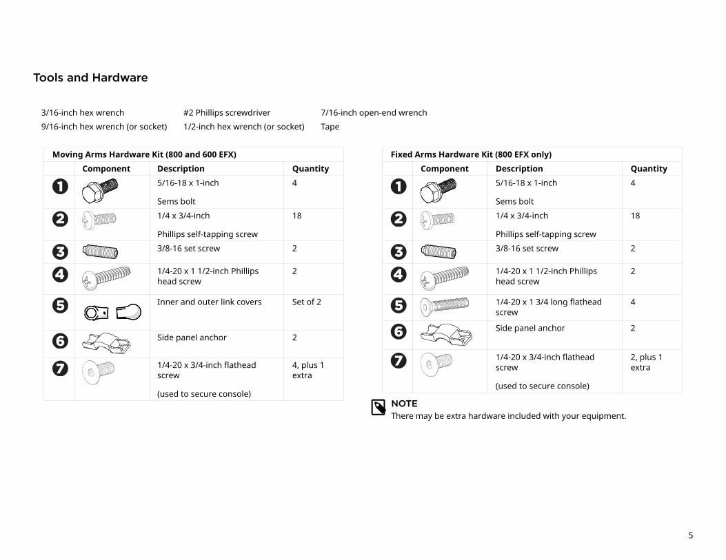
Tools and Hardware
3/16-inch hex wrench #2 Phillips screwdriver 7/16-inch open-end wrench
9/16-inch hex wrench (or socket) 1/2-inch hex wrench (or socket) Tape
Moving Arms Hardware Kit (800 and 600 EFX)
Component Description Quantity
5/16-18 x 1-inch
Sems bolt
4
1/4 x 3/4-inch
Phillips self-tapping screw
18
3/8-16 set screw 2
1/4-20 x 1 1/2-inch Phillipshead screw
2
Inner and outer link covers Set of 2
Side panel anchor 2
1/4-20 x 3/4-inch flatheadscrew
(used to secure console)
4, plus 1extra
NOTEThere may be extra hardware included with your equipment.
Fixed Arms Hardware Kit (800 EFX only)
Component Description Quantity
5/16-18 x 1-inch
Sems bolt
4
1/4 x 3/4-inch
Phillips self-tapping screw
18
3/8-16 set screw 2
1/4-20 x 1 1/2-inch Phillipshead screw
2
1/4-20 x 1 3/4 long flatheadscrew
4
Side panel anchor 2
1/4-20 x 3/4-inch flatheadscrew
(used to secure console)
2, plus 1extra
5
Install the console mount
WARNINGDO NOT attempt to connect electrical power until all assemblyprocedures are complete and properly installed.
For non-touchscreen consoles:
1. Locate the communication cable that is bundled and attached to the EFXframe.
2. Thread the communication cable upward through the center of the consolemount and out the opening at the top of the mount.
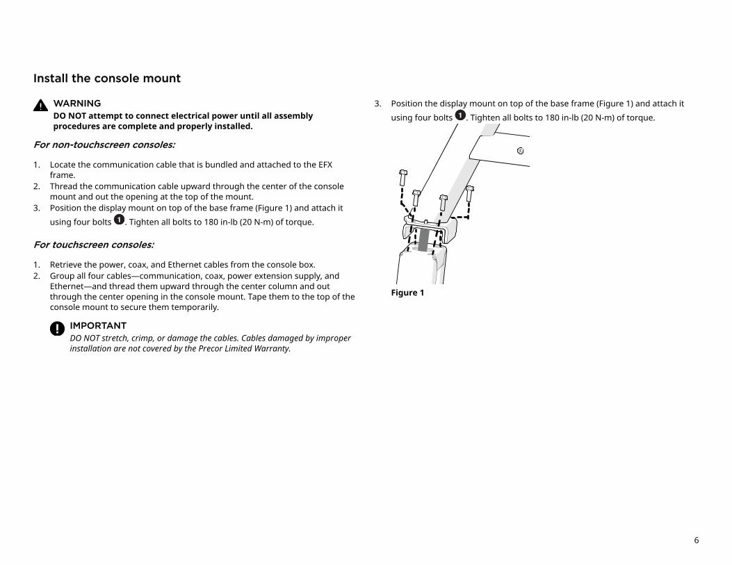
3. Position the display mount on top of the base frame (Figure 1) and attach it
using four bolts . Tighten all bolts to 180 in-lb (20 N-m) of torque.
For touchscreen consoles:
1. Retrieve the power, coax, and Ethernet cables from the console box.2. Group all four cables—communication, coax, power extension supply, and
Ethernet—and thread them upward through the center column and outthrough the center opening in the console mount. Tape them to the top of theconsole mount to secure them temporarily.
IMPORTANTDO NOT stretch, crimp, or damage the cables. Cables damaged by improperinstallation are not covered by the Precor Limited Warranty.
3. Position the display mount on top of the base frame (Figure 1) and attach it
using four bolts . Tighten all bolts to 180 in-lb (20 N-m) of torque.
Figure 1
6

Route the power supply internally
Depending on the site location and distance from an outlet, you might need toroute the power supply either internally or externally.
WARNINGDO NOT allow cables to touch any moving parts around the lift motorbody—lift screw, yoke, or ramp. Run the ramp through its movementpath a few times and have someone else watch to make sure no cablesare caught up or hanging loosely.
For non-touchscreen consoles:
Make sure the cables are secured in the cable clips C (Figure 2).
For touchscreen consoles:
1. Hook the Power Supply Bracket (included in console box) onto the rightupright support (Figure 3).
2. Coil up all cables—coax, power and Ethernet—and hold the power supply Aon the holder with one hand, and with the other hand, thread a large zip tie
around the upright support B (Figure 3).
NOTEMake sure you thread the zip tie through the designated slots in the power supply bracket.
3. Pull the zip tie tight only after you have reduced any slack by pulling the cablestighter from the top.
4. Insert the ground connector, and then secure the cables inside each of the
three cable clips C attached to the right upright support. Leave cableconnectors loose until after the lower panel is installed (see Install lower paneland front cover).
To complete the console installation, refer to the installation guide shippedwith your console.
Figure 2
Figure 3
7

Route the power supply externally
WARNINGDO NOT allow cables to touch any moving parts around the lift motorbody—lift screw, yoke, or ramp. Run the ramp through its movementpath a few times and have someone else watch to make sure no cablesare caught up or hanging loosely.
For touchscreen consoles:
1. Coil up all cables—coax, power extension A , and Ethernet—and hold them inplace with one hand, and with the other hand, thread a large zip tie aroundthe upright support (Figure 4).
NOTEMake sure you thread the zip tie through the designated slots in the
power supply bracket B .2. Pull the zip tie tight, making sure you have enough slack in the power and
extension cables.3. Insert the grounding jumper into the ground connector, and then secure the
cables inside each of the three cable clips C attached to the right uprightsupport. Leave cable connectors loose until after the lower panel is installed(see Install lower panel and front cover ).
To complete the console installation, refer to the installation guide shippedwith your console.
Figure 4
8

To install the side covers:
1. For 800 EFX only: Lift up the lower frame cover about an inch from the frame.
IMPORTANTAlthough there are two screw holes in the frame cover, DO NOT install thesescrews.
Figure 5
2. Secure each side panel using four self-tapping screws for each panel.
Figure 63. Tighten the fasteners to 35 in-lb (3.95 N-m) of torque.4. Repeat steps 2 and 3 to attach the second side panel.
5. For 800 EFX only: Press the side panels into place ensuring the latches undereach panel are secured.
Notes for 800 EFX
• Make sure cables don't catch on the latch of the forward frame cover (see Figure7) and are tied to the outside and away from the screw (see Figure 8).
• Make sure the BA clips on the lower frame cover hook over the B clips on theright and left side panels (see Figure 7). Use finesse not force to secure the partstogether with no gap between them.
BA
Figure 7 Figure 8
9

To install the lower panel and front cover:
1. Position the cover plate (packaged with hardware kit) into the center openingof the lower panel.
2. For touchscreen consoles: Install the coax coupler, star washer, and nut intothe jack plate on the lower panel and tighten (Figure 9).
3. Connect the coax cable to the inside end of the coax coupler . Tighten theconnector using a 7/16-inch open-end wrench.
NOTECheck the bend radius (about 6 inches, 15.24 cm) on the coax cable sothat it is at a natural angle.
4. Attach the Ethernet coupler into the jack plate on the lower panel (Figure9) and plug the Ethernet cable into the coupler.
Figure 9
5. For all consoles: Attach the lower panel using two screws , and route thepower cable through the slot. Fully tighten fasteners on the panel (see arrowin Figure 11).
Figure 10Figure 11
10

To install the yoke cover and shelf:
1. Attach the yoke cover to the back of the base mount using two screws(Figure 12).
NOTEMake sure the small latches engage with the side covers.
2. Fully tighten the fasteners to 35 in-lb (3.95 N-m) of torque.3. Position the shelf into the tabs near the top of the yoke cover, then secure it
using two screws (Figure 13).4. Push in the edge of the shelf and squeeze the two hooks and latches until they
engage or snap into place.
Figure 12 Figure 13
5. Attach the shelf at the top using two screws . Tighten the fasteners to 35 in-lb (3.95 N-m) of torque.
To attach the anchors:
1. Place an anchor on top of an arm frame and secure it using two screws .
Figure 142. Attach the second anchor to the other arm.
11

Install EFX arms
To install moving arms:
1. Insert the shaft of the moving arm to the center mount (Figure 15) and align pre-installed set screws to the shaft (Figure 16).
Figure 15
2. Insert one screw next to it and fully tighten all screws, including pre-installed ones to 100 in-lb (11.29 N-m) of torque.
Figure 163. Cut the zip ties holding the link arms together.
4. Place the inner cover between the link pairs and attach the link to the movingarm using a 9/16-inch socket wrench on the pre-installed bolts and tighten to100 in-lb (11.29 N-m) of torque.
Figure 175. Attach the outer link covers (shipped in hardware kit) using two Plastite®
screws and tighten them to 20 in-lb (2.25 N-m) of torque.
12

Install fixed arms (800 EFX only):
1. Install the console. For instructions, refer to the console guide included in theconsole box.
2. Install two screws into the upper display (Figure 18).
3. Insert the shaft of the arm to the center mount using two set screws .Partially tighten mounting fasteners.
4. Rotate arm assembly up and attach clamp using two flathead screws .
5. Tighten the fasteners to 100 in-lb (11.29 N-m) of torque and the fasteners to 20 in-lb (2.25 N-m).
Figure 18
13

To attach the cup holder:
1. Position the cup holder on top of the lower shelf, making sure to catch thebottom latch in the shelf component.
Figure 192. Position your hands on the arrows and press down at the top of the panel.
To complete the installation:
1. Position the badge plate on the front cover and press into place.
Figure 202. Wrap the rubber gasket on top of the badge plate from the back of the display
mount so the split is pointed toward the front. Press down to snap in two tabs at the back, then walk your hands around, wiggling and aligning the remaining tabs as you go.
3. Refer to the corresponding Console Installation Guide (found in the console box) to attach your console.
4. Plug the power cord into an appropriate outlet.
14

Notes


800/600 Line EFX Assembly Guide | 305292-101 rev A, ENU© 2018 Precor Incorporated | May 2018
Related Documents