www.tjprc.org [email protected] DYNAMIC MODELING OF DFIG WIND TURBINES M. RAMESH & T. R. JYOTHSNA Department of Electrical Engineering, Andhra University College of Engineering (A), Visakhapatnam, Andhra Pradesh, India ABSTRACT From the past few years, people are realising that renewable energy resource are sustainable energy resources because of environmental pollution and power shortage problems. With deep penetration in wind energy into the various networks, vigorous studies are carried out on DFIG based variable speed wind turbine to find out the integration between wind energy farms and power systems. These systems require accurate models of doubly fed induction generator wind turbines and their associated modeling. In this paper a dynamic model of DFIG has been derived, which can be used to simulate the DFIG wind turbine representation of the generator stator and rotor circuits. KEYWORDS: DFIG, Variable Speed, WT, Dynamic Model NOMENCLATURE Rs Stator resistance Rr Rotor resistance Ls Stator leakage inductance Lr Rotor leakage inductance Lm Magnetizing inductance Lss Stator self inductance Lrr Rotor self inductance J Inertia S Slip Ws Stator angular frequency Wr Rotor angular frequency Wm Turbine angular speed Tem Electromagnetic Torque Tmec Mechanical or load torque Tt Turbine torque ρ Air density Vν Wind speed Cp Power coefficient Received: Mar 12, 2016; Accepted: Mar 27, 2016; Published: Apr 11, 2016; Paper Id.: TJPRC:JPSMJUN20168 Original Article TJPRC: Journal of Power Systems & Microelectronics (TJPRC: JPSM) Vol. 2, Issue 1, Jun 2016, 61-72 © TJPRC Pvt. Ltd.

Welcome message from author
This document is posted to help you gain knowledge. Please leave a comment to let me know what you think about it! Share it to your friends and learn new things together.
Transcript

www.tjprc.org [email protected]
DYNAMIC MODELING OF DFIG WIND TURBINES
M. RAMESH & T. R. JYOTHSNA
Department of Electrical Engineering, Andhra University College of Engineering (A), Visakhapatnam, Andhra Pradesh, India
ABSTRACT
From the past few years, people are realising that renewable energy resource are sustainable energy resources
because of environmental pollution and power shortage problems. With deep penetration in wind energy into the various
networks, vigorous studies are carried out on DFIG based variable speed wind turbine to find out the integration
between wind energy farms and power systems. These systems require accurate models of doubly fed induction generator
wind turbines and their associated modeling. In this paper a dynamic model of DFIG has been derived, which can be
used to simulate the DFIG wind turbine representation of the generator stator and rotor circuits.
KEYWORDS: DFIG, Variable Speed, WT, Dynamic Model
NOMENCLATURE
Rs Stator resistance
Rr Rotor resistance
Ls Stator leakage inductance
Lr Rotor leakage inductance
Lm Magnetizing inductance
Lss Stator self inductance
Lrr Rotor self inductance
J Inertia
S Slip
Ws Stator angular frequency
Wr Rotor angular frequency
Wm Turbine angular speed
Tem Electromagnetic Torque
Tmec Mechanical or load torque
Tt Turbine torque
ρ Air density
Vν Wind speed
Cp Power coefficient
Received: Mar 12, 2016; Accepted: Mar 27, 2016; Published: Apr 11, 2016; Paper Id.: TJPRC:JPSMJUN20168
Original A
rticle TJPRC: Journal of Power Systems & Microelectronics (TJPRC: JPSM) Vol. 2, Issue 1, Jun 2016, 61-72 © TJPRC Pvt. Ltd.
62 M. Ramesh & T. R. Jyothsna
www.tjprc.org [email protected]
INTRODUCTION
Because of environmental pollution and power shortage people are planning to implement energy resource
programs in various governments in different countries. So many countries are recognised the importance of renewable
energy resources. In that wind is one of the best sustainable sources of energy. In the past few years, the importance of
Wind power has been penetrated into power grids. Many classifications are made to develop the wind turbine techniques.
Now, doubly fed induction generator based wind turbine is becoming so familiar [1]; DFIG WT has the advantages of
economic in construction, flexible control and high transfer energy efficiency, and three phase winding of the stator is
directly connected to the grid , and three phase windings of the rotor is connected to the converters through slip rings.
Because of supplying of exciting current from converters to the DFIG, the rating of converters in DFIG is considerably low
and which is 20-25% of rating of DFIG. Flexibility of control in DFIG can be achieved by using IGBT based converters
and these controllers can impact on stability of the system [2].
DOUBLY FED INDUCTION GENERATORS
• Doubly Fed Induction Generator model
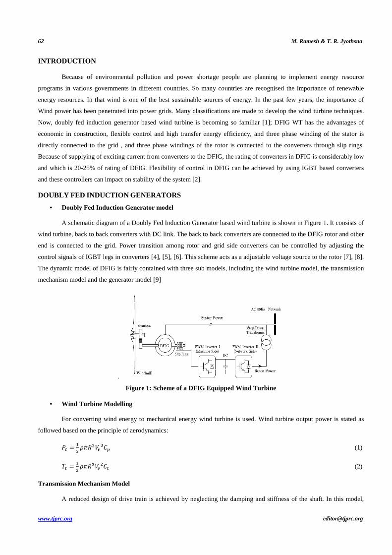
A schematic diagram of a Doubly Fed Induction Generator based wind turbine is shown in Figure 1. It consists of
wind turbine, back to back converters with DC link. The back to back converters are connected to the DFIG rotor and other
end is connected to the grid. Power transition among rotor and grid side converters can be controlled by adjusting the
control signals of IGBT legs in converters [4], [5], [6]. This scheme acts as a adjustable voltage source to the rotor [7], [8].
The dynamic model of DFIG is fairly contained with three sub models, including the wind turbine model, the transmission
mechanism model and the generator model [9]
.
Figure 1: Scheme of a DFIG Equipped Wind Turbine
• Wind Turbine Modelling
For converting wind energy to mechanical energy wind turbine is used. Wind turbine output power is stated as
followed based on the principle of aerodynamics:
=
(1)
=
(2)
Transmission Mechanism Model
A reduced design of drive train is achieved by neglecting the damping and stiffness of the shaft. In this model,
Dynamic Modeling of DFIG Wind Turbines 63
www.tjprc.org [email protected]
only one single inertia is measured as summation of inertia of turbine and inertia of rotor and equivalent torque based
equation is stated as follows:
− = Ω
(3)
Based on assumptions the one-mass model of the shaft in wind system is stiff and other constructed moving parts
are lumped together.
Generator Model
The dynamic analysis of a Doubly Fed Induction Generator is done by using α-β and the d – q model[14],[15].
Variables of stator and rotor are related with relevant reference frames in this model which can deal the characteristics in
more realistic way. The generator model of DFIG can be expressed by voltage equations, power and electromagnetic
torque equations under the α-β coordinate system [14],[16].
Voltage Equations
α = α + .ϕα
(4)
= + .ϕ
(5)
α = α + .ϕα
+ ∗ ϕ
(6)
= + .ϕ
− ∗ ϕα
(7)
Power Equations
=
(α α + ) (8)
=
(α α + ) (9)
% =
( α − α) (10)
% =
( α − α) (11)
Electromagnetic Torque Equation
&' =
((α_ (α) (12)
D-Q Modelling
In doubly fed induction generator, flux linkage is chosen as basic variable for representing [17],[18] the d-q axis
used for simulation. This representation is based on two axis full-order known as the Park model [10]. There is an
equivalent two-axis representation of three axis. In that stator direct axis is represented as ds and quadrature axis is
represented as qs, and Rotor direct axis is represented as dr and rotor quadrature axis is represented as qr. Here a
synchronously rotating reference frame chosen as d-q reference frame which is rotating at synchronous speed. There by
interaction among electromagnetic torque and current in rotor is observed. In this model three-phase quantities are changed
to the two-phase quantities [11],[12].The generator model of DFIG can be expressed by voltage equations, power and
64 M. Ramesh & T. R. Jyothsna
www.tjprc.org [email protected]
electromagnetic torque equations under the d-q coordinate system.
Voltage Equations
= +*+,
- - (. (13)
. = . +*/,
+ j ( (14)
= +*+0
+ j( 1 ')(. (15)
. = . +*/0
- j( 1 ')( (16)
Flux Linkage Equations
( = 2 + 2' (17)
(. = 2. + 2'. (18)
( = 2 + 2' (19)
(. = 2. + 2'. (20)
Electromagnetic Torque Equation
&' =
3
3,((._ (.) (21)
Power Equations
=
(α α + ) (22)
=
(α α + ) (23)
% =
( α − α) (24)
% =
( α − α) (25)
SIMULATION RESULTS
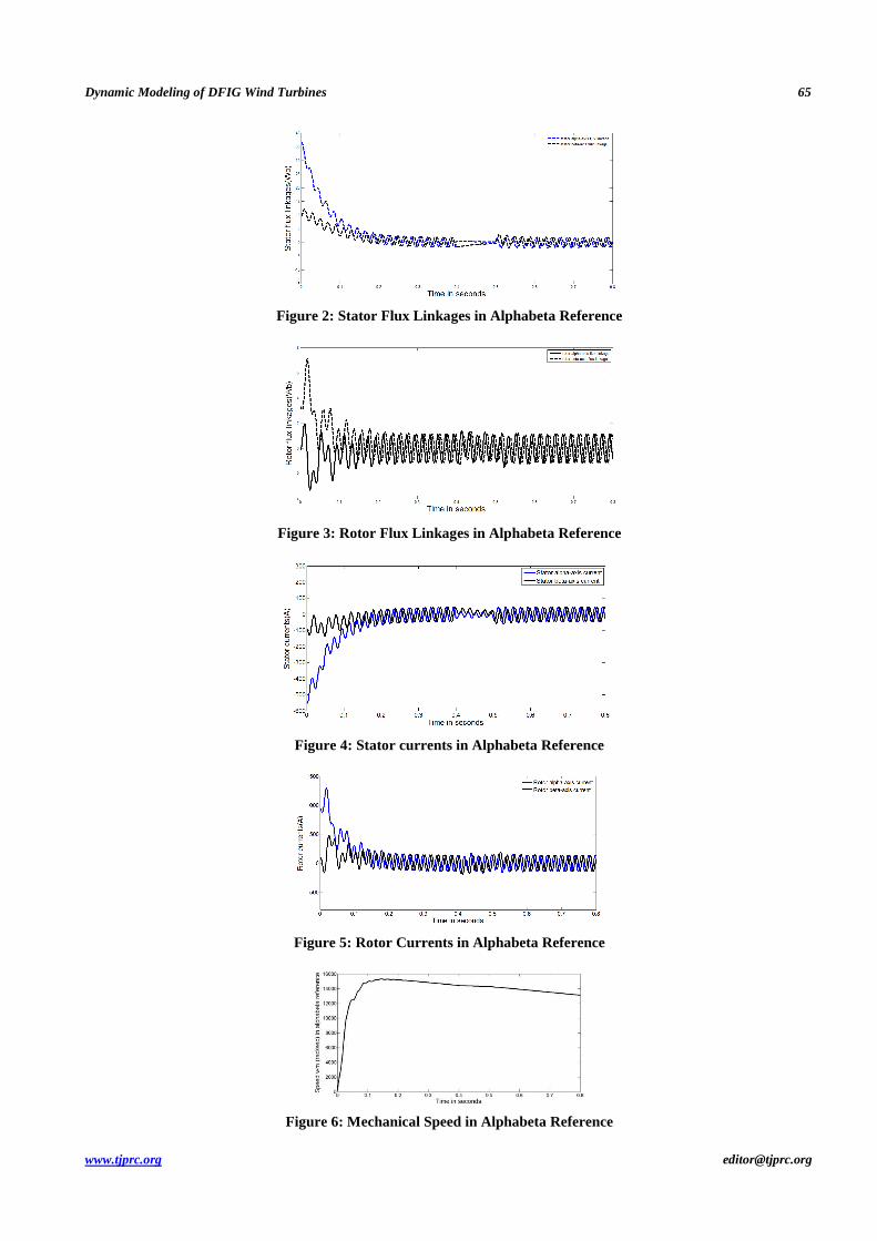
A simulation study was performed on a 2MW 690V DFIG with synchronous speed of 1500 rev/min, rated stator
current is 1760A and other relevant parameters are specified in DFIG turbine parameter table. Based on alpha and beta
modeling, stator flux linkages, rotor flux linkages, stator currents, rotor currents, speed of the rotor and Electromagnetic
torque parameters are shown in Figure 2 to Figure 7.
Dynamic Modeling of DFIG Wind Turbines 65
www.tjprc.org [email protected]
Figure 2: Stator Flux Linkages in Alphabeta Reference
Figure 3: Rotor Flux Linkages in Alphabeta Reference
Figure 4: Stator currents in Alphabeta Reference
Figure 5: Rotor Currents in Alphabeta Reference
Figure 6: Mechanical Speed in Alphabeta Reference

66 M. Ramesh & T. R. Jyothsna
www.tjprc.org [email protected]
Figure 7: Electromagnetic Torque in Alphabeta Reference
Based on d-q modeling, stator flux linkages, rotor flux linkages, stator currents, rotor currents, speed of the rotor
and Electromagnetic torque parameters are shown in Figure 8 to Figure 17.
Figure 8: Stator d-Axis Flux Linkage in d-q Reference
Figure 9: Stator q-Axis Flux Linkage in d-q Reference
Figure 10: Rotor d-Axis Flux Linkage in d-q Reference

Dynamic Modeling of DFIG Wind Turbines 67
www.tjprc.org [email protected]
Figure 11: Rotor q-Axis Flux Linkage in d-q Reference
Figure 12: Speed in d-q Reference
Figure 13: Stator d-Axis Current in d-q Reference
Figure 14: Stator q-Axis Flux Linkage in d-q Reference
Figure 15: Rotor d-axis flux linkage in d-q reference

68 M. Ramesh & T. R. Jyothsna
www.tjprc.org [email protected]
Figure 16: Rotor q-Axis Flux Linkage in d-q Reference
Figure 17: Electromagnetic Torque in Alphabeta Reference
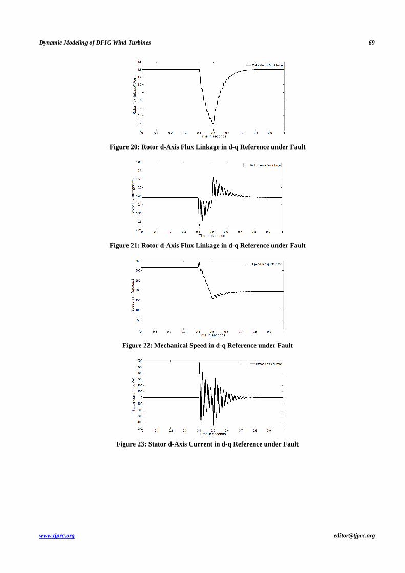
A disturbance is created with a duration of two seconds which is between 0.4 sec to 0.6 sec in d-q modeling of
DFIG equipped with wind turbine is shown in Figure 18 to Figure 27.
Figure 18: Stator d-Axis Flux Linkage in d-q Reference under Fault
Figure 19: Stator d-Axis Flux Linkage in d-q Reference under Fault
Dynamic Modeling of DFIG Wind Turbines 69
www.tjprc.org [email protected]
Figure 20: Rotor d-Axis Flux Linkage in d-q Reference under Fault
Figure 21: Rotor d-Axis Flux Linkage in d-q Reference under Fault
Figure 22: Mechanical Speed in d-q Reference under Fault
Figure 23: Stator d-Axis Current in d-q Reference under Fault

70 M. Ramesh & T. R. Jyothsna
www.tjprc.org [email protected]
Figure 24: Stator q-Axis Current in d-q Reference under Fault
Figure 25: Rotor d-Axis Current in d-q Reference under Fault
Figure 26: Rotor q-Axis Flux Linkage in d-q Reference under Fault
Figure 27: Stator d-Axis Flux Linkage in d-q Reference under Fault
Table 1: DFIG Wind Turbine Parameters
Parameter Value Units Prated 2 MW
Rs 2.6 mΩ Rr 2.9 mΩ Ls 2.587 mH Lr 2.587 mH Lm 2.5 mH Slip -0.25 NA

Dynamic Modeling of DFIG Wind Turbines 71
www.tjprc.org [email protected]
CONCLUSIONS
Because of problems encountered in power sector needful and accurate modeling has to be done to give a remedy
for power shortage. In order to get that simulation of DFIG based wind turbine has been done under fault condition and
hence a dynamic model with full-order representation for the DFIG and its associated circuits has been developed.
REFERENCES
1. Eriksen, P.B., Ackermann, T., Abildgaard, H., Smith, P., Winter, W., and Rodriguez Garcia, J.M.: ‘System operation with high
wind penetration’, IEEE Power Energy Mag., 2005, 3, (6), pp. 65–74.
2. Lei, Y., Mullane, A., Lightbody, G., and Yacamini, R.: ‘Modeling of the wind turbine with a doubly fed induction generator for
grid integration studies’, IEEE Trans. Energy Convers., 2006, 21, (1), pp. 257–264.
3. Mei, F., and Pal, B.C.: ‘Modelling and small-signal analysis of a grid connected doubly-fed induction generator’. Proc. of
IEEE PES General Meeting, 2005, San Francisco, USA.
4. S. Doradla, S. Chakrovorty, and K. Hole, “A new slip power recovery scheme with improved supply power factor,” IEEE
Trans. Power Electron.,vol. PE-3, no. 2, pp. 200–207, Apr. 1988.
5. R. Pena, J. Clare, and G. Asher, “Doubly fed induction generator using back-to-back pwm converters and its application to
variable-speed wind energy generation,” Proc. Inst. Elect. Eng., Electric Power Applications,vol. 143, no. 3, pp. 231–241,
May 1996.
6. Y. Tang and L. Xu, “A flexible active and reactive power control strategy for a variable speed constant frequency generating
system,” IEEE Trans. Power Electron., vol. 10, no. 4, pp. 472–478, Jul. 1995.
7. A. Feijo, J. Cidrs, and C. Carrillo, “Third order model for the doubly-fed induction machine,” Elect. Power Syst. Res., vol. 56,
pp. 121–127, Mar.2000.
8. P. Kundur, Power System Stability and Control. New York: McGraw-Hill, 1994.
9. Y. Xu and N. Wang, “Study on dynamic equivalence of wind farms with DFIG based on clustering analysis,” J. North China
Elect. Power Univ., vol. 40, no. 3, pp. 1–5, 2013.
10. G.R.Slemon, “Modelling Induction Machines for Electric Drives”, IEEE Transaction on Industry Application Vol.25, No.6 pp
1126-1131, Nov 1989.
11. A. Petersson, “Analysis, Modeling and Control of Doubly-Fed Induction Generators for Wind Turbines”, Licentiate Thesis,
Dept. Electric Power Engineering, Chalmers University of Technology, Sweden 2003.
12. S.Muller,M.Deicke and Rik W.De.Doncker,“Doubly-fed Induction Generator systems for Wind Turbines,” IEEE Industry
Applications Magazine, May-June, 2002.
13. S.A. Papatbanassiou, M.P. Papadopoulos, “Dynamic behavior of variable speed wind turbines under stochastic wind”, tEEE
Transactions on Energy Conversion, vol. 14, no.4, December 1999, pp.1617-l 623.
14. Ekanayake, J.B., Holdsworth, L., Wu, X.G., and Jenkins, N.: ‘Dynamic modeling of doubly fed induction generator wind
15. turbine’, IEEE Trans. Power Syst., 2003, 18, (2), pp. 803–809.
16. M.Y. Uctug & I. Eskandarzeh, H. Ince, “Modelling and output power optimisation of a wind turbine driven double output
induction generator”, IEE Proceedings-Electric power applications, vol. 141, no,2, March 1994,pp.33-38.
17. J. G. Slootweg, H. Polinder, and W. L. Kling, “Dynamic modeling of a wind turbine with doubly fed induction generator,” in
72 M. Ramesh & T. R. Jyothsna
www.tjprc.org [email protected]
Proc. IEEE Power Eng. Soc. Summer Meeting, Vancouver, BC, Canada, July 15-19, 2001.
18. F. Mei and B. Pal, “Modal analysis of grid-connected doubly fed induction generators,” IEEE Trans. Energy Convers., vol.
22, no. 3, pp.728–736, Aug. 2007.
19. P. Krause, Analysis of Electric Machinery. New York: McGraw-Hill,1986.
20. A. Peterson, “Analysis, Modeling and Control of Doubly-Fed Induction Generators for Wind Turbines.” Ph.D. thesis,
Chalmers University of Technology, Goteborg, Sweden, 2005.
Related Documents