C h a p t e r 8 ■■■B waves HR Learning Objectives At the end of this chapter the students will be able to : 1. Recall the generation and propagation of waves. 2. Describe the nature of the motions in transverse and longitudinal waves. 3. Understand and use the terms wavelength, frequency and speed of wave. 4. Understand and use the equation v-f\ 5. Understand and describe Newton’s formula of speed of sound. 6. Derive Laplace correction in Newton's formula of speed of sound for air. 7. Derive the formula v= v0 + 0.61 i. 8. Recognize and describe the factors on which speed of sound in air depends. 9. Explain and use the principle of superposition. 10. Understand the terms interference and beats. 11. Describe the phenomena of interference and beats giving examples of sound waves. 12. Understand and describe reflection of waves. 13. Describe experiments, which demonstrate stationary waves for stretched strings and vibrating air columns. 14. Explain the formation of a stationary wave using graphical method. 15. Understand the terms node.and anti-node. 16. Understand and describe modes of vibration of string. 17. Understand and describe Doppler's effect and its causes. 18. Recognize the applications of Doppler's effect in radar, sonar, astronomy, satellite and radar speed traps. 161

Welcome message from author
This document is posted to help you gain knowledge. Please leave a comment to let me know what you think about it! Share it to your friends and learn new things together.
Transcript

C h a p t e r 8
■ ■ ■ B waves HRLearning Objectives
At the end of this chapter the students will be able to :
1. Recall the generation and propagation of waves.
2. Describe the nature of the motions in transverse and longitudinal waves.3. Understand and use the terms wavelength, frequency and speed of wave.
4. Understand and use the equation v - f \
5. Understand and describe Newton’s formula of speed of sound.6. Derive Laplace correction in Newton's formula of speed of sound for air.7. Derive the formula v= v0 + 0.61 i.
8. Recognize and describe the factors on which speed of sound in air depends.9. Explain and use the principle of superposition.
10. Understand the terms interference and beats.
11. Describe the phenomena of interference and beats giving examples of soundwaves.
12. Understand and describe reflection of waves.13. Describe experiments, which demonstrate stationary waves for stretched strings
and vibrating air columns.
14. Explain the formation of a stationary wave using graphical method.
15. Understand the terms node.and anti-node.16. Understand and describe modes of vibration of string.17. Understand and describe Doppler's effect and its causes.18. Recognize the applications of Doppler's effect in radar, sonar, astronomy, satellite
and radar speed traps.
161

w aves transport energy without transporting matter.The energy transportation is carried by a disturbance, which , spreads out from a source. We are well familiar with different types of waves such as water waves in the ocean, or gently formed ripples on a still pond due to rain drop. When a musician plucks a guitar-string, sound waves are generated which on reaching our ear, produce the sensation of music. Wave disturbances may also come in a concentrated bundle like the shock waves from an aeroplane flying at supersonic speed. Whatever may be the nature of waves, the mechanism' by which it transports energy is the same. A succession of oscillatory motions are always involved. The wave is generated by an oscillation in the vibrating body and propagation of wave through space is by means of oscillations. The waves'which propagate by the oscillation of material particles are known as mechanical waves.
There is another class of waves which, instead of material particles, propagate out in space due to oscillations ofelectric and magnetic fields. Such waves are known aselectromagnetic waves. We will undertake the study ofelectromagnetic waves at a later stage. Here we will
radars travel just a few centimetres consider the mechanical waves only. The waves generatedin water, whereas highly directional r . , .beams of ultrasonic waves can be in ropes, strings, coil of springs, water and air are allmade to travel many kilometres mechanical waves.’
So far wc have been considering motion o f individual particles but in case of mechanical waves, we study the collective motion o f particles. An example will help us here. If youMook at a black and white picture in a newspaper with a magnifying glass, you will discover that the picture is made up o f many closely spaced dots. If you do not use the magnifier, you do not see the dots. What .you see is the collective effect of dots in the form of a picture. Thus what we sec as mechanical wave is actually the effect o f oscillations o f a very large number o f particles o f the medium through which the wave is passing.
8.1 PROGRESSIVE WAVESDrop a pebble into water. Ripples will be produced and spread out across the water. The ripples are the examples of progressive waves because they carry energy across
Do You Know?Ultrasonic waves are particularly useful for undersea communication and detection systems. High frequency radio waves, used in
162

the water surface. A wave, which transfers energy by moving away from the source of disturbance, is called a progressive or travelling wave. There are two kinds of progressive waves - transverse waves and longitudinal waves.
Transverse and Longitudinal WavesConsider two persons holding opposite ends of a rope or a hosepipe. Suddenly one person gives one up and down jerk to the rope. This disturbs the rope and creates a hump in it which travelsalongtheropetowardstheotherperson(Fig.8.1 a & b).
Fig. 8.1
When this hump reaches the other person, it causes his hand to move up (Fig. 8.1 c). Thus the energy and momentum imparted to the end of the rope by the first person has reached the other end of the rope by travelling through the rope i.e., a wave has been set up on the rope in the form of a moving hump. We call this type of wave a pulse. The forward motion of the pulse from one end of the rope to the other is an example of progressive wave. The hand jerking the end of the rope is the source of the wave. The rope i$ th£ medium in which the wave moves.
163
Transverse waves
Fig. 8.2(a)
Longitudinal waves
Fig. 8.2(b)
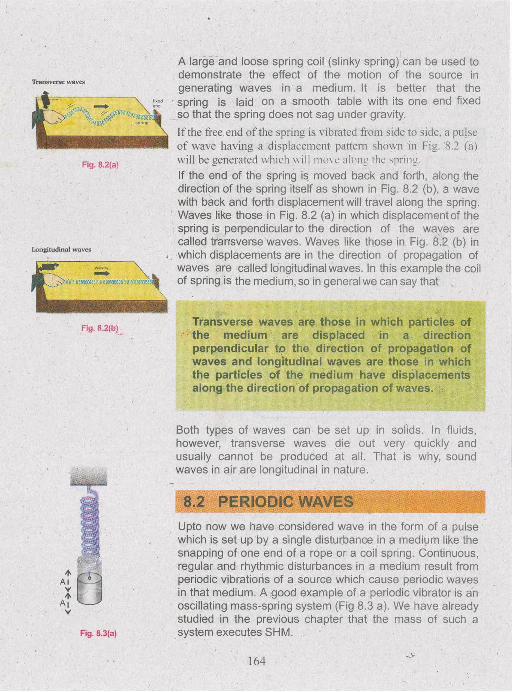
A large and loose spring coil (slinky spring) can be used to demonstrate the effect of the motion of the source in generating waves in a medium. It is better that the spring is laid on a smooth table with its one end fixed so that the spring does not sag under gravity.If the free end of the spring is vibrated from side to side, a pulse of wave having a displacement pattern shown in Fig. '8.2 (a) will be generated which \\ ill mo\ e along the spring.If the end of the spring is moved back and forth, along the direction of the spring itself as shown in Fig. 8.2 (b), a wave with back and forth displacement will travel along the spring. Waves like those in Fig. 8.2 (a) in which displacement of the spring is perpendicular to the direction of the waves are called transverse waves. Waves like those in Fig. 8.2 (b) in which displacements are in the direction of propagation of waves are called longitudinal waves. In this example the coil of spring is the medium, so in general we can say that
Transverse waves are those in which particles of the medium are displaced in a direction perpendicular to the direction of propagation of waves and longitudinal waves are those in which the particles of the medium have displacements along the direction of propagation of waves.
Both types of waves can be set up in solids. In fluids, however, transverse waves die out very quickly and usually cannot be produced at all. That is why, sound waves in air are longitudinal in nature.
8.2 PERIODIC WAVES
Fig. 8.3(a)
Upto now we have considered wave in the form of a pulse which is set up by a single disturbance in a medium like the snapping of one end of a rope or a coil spring. Continuous, regular and rhythmic disturbances in a medium result from periodic vibrations of a source which cause periodic waves in that medium. A good example of a periodic vibrator is an oscillating mass-spring system (Fig 8.3 a). We have already studied in the previous chapter that the mass of such a system executes SHM.
164
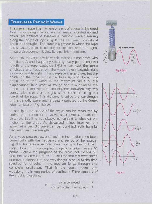
Transverse Periodic WavesImagine an experiment where one end of a rope is fastened to a mass spring vibrator. As the mass vibrates up and down, we observe a transverse periodic wave travelling along the length of rope (Fig. 8.3 b). The wave consists of crests and troughs. The crest is a pattern in which the rope is displaced above its equilibrium position, and in troughs, it has a displacement below its equilibrium position.
As the source executes harmonic motion up and down with amplitude A and frequency f, ideally every point along the length of the rope executes SHM in turn, with the same amplitude and frequency. The wave travels towards right as crests and troughs in turn, replace one another, but the points on the rope simply oscillates up and down. The amplitude of the wave is the maximum value of the displacement in a crest or trough and it is equal to the amplitude of the vibrator. The distance between any two consecutive crests or troughs is the same all along the length of the rope. This distance is called the wavelength of the periodic wave and is usually denoted by the Greek letter lambda X (Fig. 8.3 b).
In principle, the speed of the wave can be measured by timing the motion of a wave crest over a measured distance. But it is not always convenient to observe the motion of the crest. As discussed below, however, the speed of a periodic wave can be found indirectly from its frequency and wavelength.
As a wave progresses, each point in the medium oscillates periodically with the frequency and period of the source. Fig. 8.4 illustrates a periodic wave moving to the right, as it might look in photographic snapshots taken every % period. Follow the progress of the crest that started out from the extreme left at t = 0. The time that this crest takes to move a distance of one wavelength is equal to the time required for a point in the medium to go^.through one complete oscillation. That is the crest moves one wavelength X in one period of oscillation 7".Th^ speed v of the crest is therefore,
Fig. 8.3(b)
Fig. 8.4
V = distance movedcorresponding time interval
165

All parts of the wave pattern move with the same speed, so the speed of any one crest is just the speed of the wave/ We can therefore, say that the speed v of the waves is
* = (8 .1)
but y = f, where f is the frequency of the wave. It is the
same as the frequency of the vibrator, generating the waves. Thus Eq. 8.1 becomes
v = n (8.2)
Phase Relationship between two Points on a WaveThe profile of periodic waves generated by a source executing SHM is represented by a sine curve. Figure 8.5 shows the snapshot of a periodic wave passing through a medium. In this figure, set of points are shown which are moving in unison as the periodic wave passes. The points C and C ' , as they move up and down, are always in the same state of vibration i.e., they always have identical displacements and velocities. Alternatively, we can say that as the wave passes, the points C ad C' move in phase. We may also say that C ' leads C by one time period or 2n radian. Any point at a distance x, C lags behind by phase angle q> = 2nx
ASo is the case with points D and D' . Indeed there are infinitely many such points along the medium which are vibrating in phase. Points separated from one anotherthrough distances of A, 2A, 3A, ........ are all in phase witheach other. These points can be anywhere along the wave and need not correspond with only the highest and lowestpoints. For example, points such as P, P ' , P" .............are all in phase. Each is separated from the next by a distance A.Some of the points are exactly out of step. For example, when point C reaches its maximum upward displacement, at the same time D reaches its maximum downward displacement. At the instant that C begins to go down, D begins to move up. Points such as these are called one half period out of phase. Any two points separated fromone another by 3 ^ , 5 ^ , are out of phase.

Longitudinal Periodic WavesIn the previous section we have considered the generation of transverse periodic waves. Now we will see how the longitudinal periodic waves can be generated.
Consider a coil of spring as shown in Fig. 8.6. It is suspended by threads so that it can vibrate horizontally. Suppose an oscillating force F is applied to its end as indicated. The force will alternately stretch and compress the spring, thereby sending a series of stretched regions (called rarefaction) and compressions down the spring. We will see the oscillating force causes a longitudinal wave to move down the spring. This type of wave generated in springs is also called a compressional wave. Clearly in a compressional wave, the particles in the path of wave move back and forth along the line of propagation of the wave.
Notice in Fig. 8.6, the supporting threads would be exactly vertical if the spring were undisturbed. The disturbance passing down the spring causes displacements of the elements of the spring from their equilibrium positions. In Fig. 8.6, the displacements of the thread from the vertical are a direct measure of the displacements of the spring elements. It is, therefore, an easy way to graph the displacements of the spring elements from their equilibrium positions and this is done in the lower part of the figure.
8.3 SPEED OF SOUND IN AIRSound waves are the most important examples of longitudinal or compressional waves. The speed of sound waves depends on the compressibility and inertia of the medium through which they are travelling. If the medium has the elastic modulus E and densityp then, speed v is given by
v = (8.3)
As seen from the table 8.1, the speed of sound is much higher in solids than in gases. This makes sense because the molecules in a solid are closer than in a gas and hence, respond more quickly to a disturbance.
In general, sound travels more slowly in gases than in solids because gases are more compressible and hence
Table 8.1Speed of sound In different media
Medium Speedms'1
Solids at 20°CLead 1320Copper 3600Aluminium 5100Iron 5130Glass 5500
Liauids at 20°CMethanol 1120Water 1483
Gases at S.T.P.Carbon dioxide 258Oxygen 315Air 332Helium 972Hydogen 1286
167
have a smaller elastic modulus. For the calculation of elastic modulus for air, Newton assumed that when a sound wave travels through air, the temperature of the air during compression remains constant and pressure changes from P to (P+AP) and therefore, the volume changes from V to (V - AV). According to Boyle’s law
PV = (P + A P )(V - AV) ............ (8.4)
or P V = P V ~ PAV + VAP - APAV
The product AP AV is very small and can be neglected. So, the above equation becomes
AP APPAV=VAP or P . — x V m —
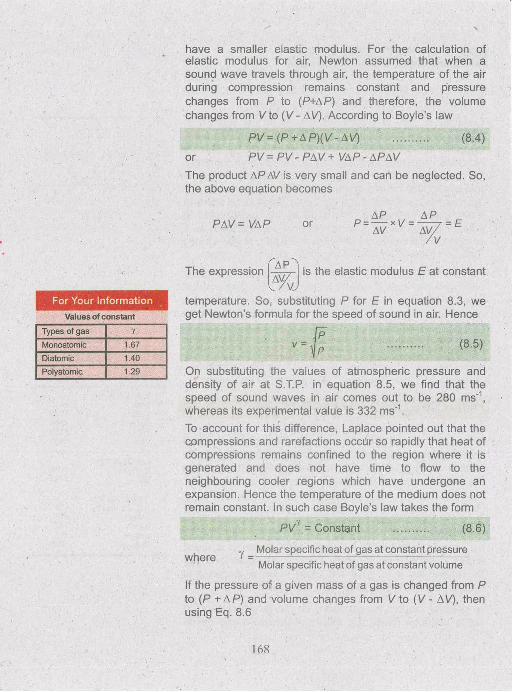
For Your InformationValues of constant
The expression is the elastic modulus E at constantv , / v j
temperature. So, substituting P for E in equation 8.3, we
Types of gas YMonoatom ic 1.67Diatomic 1.40Polyatomic 1.29
get Newton’s formula for the speed of sound in air. Hence
(8.5)
On substituting the values of atmospheric pressure and density of air at S.T.P. in equation 8.5, we find that the speed of sound waves in air comes out to be 280 ms'1, whereas its experimental value is 332 ms'1.To account for this difference, Laplace pointed out that the compressions and rarefactions occdr so rapidly that heat of compressions remains confined to the region where it is generated and does not have time to flow to the neighbouring cooler regions which have undergone an expansion. Hence the temperature of the medium does not remain constant. In such case Boyle’s law takes the form
PVy = Constant (8 .6 )
where Y = Molar specific heat of gas at constant pressure Molar specific heat of gas at constant volume
If the pressure of a given mass of a gas is changed from P to (P + A P ) and volume changes from V to (V - AV), then using Eq. 8.6
168
P V 1 = (P + A P )(V - AV)'
PV = (P + AP)V'
Applying Binomial theorem
1 - ^
1-AV AV1 - y + negligible terms
Hence P = ( P +AP)'■ ’ V
or
where
AV ' AVP = P - y P- + AP- y A P----\/ V
is negligible.. Hence, we have
AV0= -YP + AP
\/
orAPAV /
= Y P =E
Thus elastic modulusr
APa\7/
/ V J
equals Y p.
Hence,substituting the value of elastic modulus in Eq. 8.3, we get Laplace expression for the speed of sound in a gas
I r P ■ (8.7)
For air Y = 1.4 so at S.T.P.
v - Vi .4 X 280 m s'1 = 333 ms'
This value is very close to the experimental value.
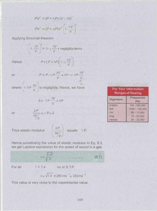
For Your Information Ranges of Hearing
Organisms Frequencies(Hz)
DolphinBatCatDogHuman
150- 150,000 1000- 120,000
60 - 70,000 15-50,000 20-20,000
169

Effect of Variation of Pressure, Density and Temperature on the Speed of Sound in a Gas1. Effect of Pressure: Since density is proportional
to the pressure, the speed of sound is not affected by a variation in the pressure of the gas.
2. Effect of Density: At the same temperature and pressure for the gases having the same value of Y, the speed is inversely proportional to the square root of their densities Eq. 8.7. Thus the speed of sound in hydrogen is four times its speed in oxygen as density of oxygen is 16 times that of hydrogen.
3. Effect of Temperature: When a gas is heated atconstant pressure, its volume is increased and hence its density is decreased. As
v=
So, the speed is increased with rise in temperature.
Let
v0 = Speed of sound at 0 °C , pQ - Density of gas at 0 °C
vt = Speed of sound at t °C , Pt = Density of gas at t °C
then v0 = and vt =V P0 4 V Pt
Hence’ (88)
We have studied the volume expansion of gases in previous classes. If Vo is the volume of a gas at temperature 0 °C and Vt is volume at t °C, then
Vt = V0 (1 + p t)
Where p is the coefficient of volume expansion of the gas.1
For all gases, its value is a b o u t . Hence

Since
Hence
or
Volume =
m m
p, p.
massdensity
P 0= P tV.
273
t273
Putting the value of pQ in equation 8.8 we have,
or
l . L X, V 273
V, [273 I Y
v0 v 2 7 3 \ r 0
(8.9)
(8.10)V . V V l n
where T and T0 are the absolute temperaturescorresponding to t °C and 0 °C respectively. Thus, thespeed of sound varies directly as the square root ofabsolute temperature
Expanding the R.H.S. of equation (8.9), using Binomial theorem and neglecting higher powers, we have
1 +—546v _y
0r &As vQ = 332 ms
putting this value in the 2nd factor
332Then v,= vn+ ------- 1
' 546
or vt = va + 0.61 t (8 .11)
Example 8 .1 : Find the temperature at which the velocity of sound in air is two times its velocity at 10 °C.
Solution: 10 °C = 10 °C + 273 = 283 K
Suppose at T K, the velocity is two times its value at 283 K.
Do You Know?
Slower than the speed of sound.
Faster than the speed of sound.
What happens when a jet plane like Concorde flies faster than the speed of sound?A conical surface of concentrated sound energy sweeps over the ground as a supersonic plane passes overhead. It is known as sonicboom.
171
“ISince
■ Therefore,<fr-
or
- P -V 283 K
r n2S3 V 283 K
Fig. 8.7
wave 1
Superposition of two waves of the same frequency which are exactly ir
Wave 1 and 2 super posed
resultant wave
V = 0Superposition of two waves of the same frequency which are exactly out of phase.
V2S3
T= 1132 K or 859 °C
H ^ m ^ P E R P O S I T I i
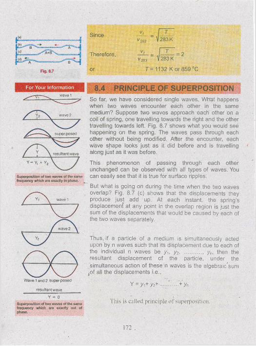
So far, we have considered single waves. Wh'at happens when two waves encounter each other in the same medium? Suppose two waves approach each other on a coil of spring, one travelling towards the right and the other travelling towards left. Fig. 8.7 shows what you would see happening on the spring. The waves pass through each other without being modified. After the encounter, each wave shape looks just as it did before and is travelling along just as it was before.
This phenomenon of passing through each other unchanged can be observed with all types of waves. You can easily see that it is true for surface ripples.
But what is going on during the time when the two waves overlap? Fig. 8.7 (c) shows that the displacements they produce just add up. At each instant, the spring’s displacement at any point in the overlap region is just the sum of the displacements that would be caused by each of the two waves separately.
Thus, if a particle of a medium is simultaneously acted upon by n waves such that its displacement due to each ofthe individual n waves be yi, y2, ......... ' yn, then theresultant displacement of the particle, under the simultaneous action of these n waves is the algebraic'sum
jOf all the displacements i.e.,
Y = y,+ y2+ + yn
This is called principle o f superposition.
172
Again, if two waves which cross each other have opposite phase, their resultant displacement will be
V = yi - y2
Particularly if yi = yi then result displacement Y= 0. Principle of superposition leads to many interesting phenomena with waves.
i) Two waves having same frequency andtravelling in the same direction (Interference).
ii) Two waves of slightly different frequencies andtravelling in the same direction (Beats)
iii) Two waves of equal frequency travelling inopposite direction (Stationary waves).
________ .___________ s,
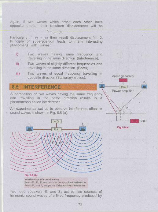
:.5 ERFERENCESuperposition of two waves having the same frequency and travelling in the same direction results in a phenomenon called interference.
An experimental set up to observe interference effect in sound waves is shown in Fig. 8.8 (a).
Fig. 8.8 (b)
Interference of sound wavesPoints P,, Pv P5 are points of constructive interference.Points P2 and P4 are points of destructive interference.
Two loud speakers St and S2 act as two sources of harmonic sound waves of a fixed frequency produced by
Audio generator
T
Fig. 8.8(a)
173
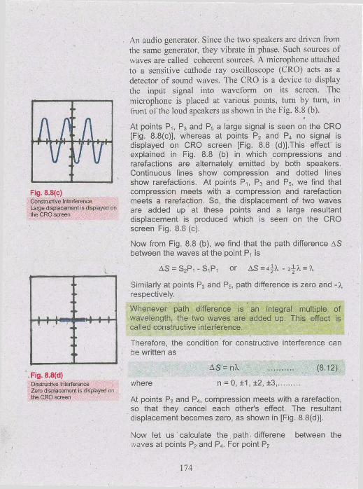
Fig. 8.8(c)Constructive Interference Large displacement is displayed on the CRO screen
Fig. 8.8(d)Destructive InterferenceZero displacement is displayed onthe CRO screen
An audio generator. Since the two speakers are driven from the same generator, they vibrate in phase. Such sources of waves are called coherent sources. A microphone attached to a sensitive cathode ray oscilloscope (CRO) acts as a detector of sound waves. The CRO is a device to display the input signal into waveform on its screen. The microphone is placed at various points, turn by turn, in front o f the loud speakers as shown in the Fig. 8.8 (b).
t
At points Pi, P3 and P5 a large signal is seen on the CRO [Fig. 8.8(c)], whereas at points P2 and P4 no signal is displayed on CRO screen [Fig. 8.8 (d)].This effect is explained in Fig. 8.8 (b) in which compressions and rarefactions are alternately emitted by both speakers. Continuous lines show compression and dotted lines show rarefactions. At points P^ P3 and P5> we find that compression meets with a compression and rarefaction meets a rarefaction. So, the displacement of two waves are added up at these points and a large resultant displacement is produced which is seen on the CRO screen Fig. 8.8 (c).
Now from Fig. 8.8 (b), we find that the path difference AS between the waves at the point Pi is
AS — S2Pi ■ S 1P1 or AS — 4-J-X - 34-A. — %
Similarly at points P3 and P5, path difference is zero and respectively.
Whenever path difference is an integral multiple of wavelength, the two waves are added up. This effect is called constructive interference.
Therefore, the condition for constructive interference can be written as
where
A S = nX
n = 0, ±1, ±2, ±3,
(8 .12)
At points P2 and P4, compression meets with a rarefaction, so that they cancel each other’s effect. The resultant displacement becomes zero, as shown in [Fig. 8.8(d)].
Now let us calculate the path-differene between the waves at points P2 and P4. For point P2
174
Similarly at P4 the path difference is X.2
So, at points where the displacements of two waves cancel each other's effect, the path difference is an odd integral multiple of half the wavelength. This effect is called destructive interference.
Therefore, the condition for destructive interference can be written as
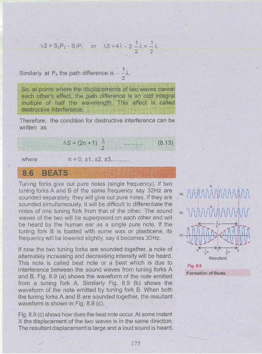
Tuning forks give out pure notes (single frequency). If two tuning forks A and B of the same frequency say 32Hz are sounded separately, they will give out pure notes. If they are sounded simultaneously, it will be difficult to differentiate the notes of one tuning fork from that of the other. The sound waves of the two will be superposed on each other and will be heard by the human ear as a single pure note. If the tuning fork B is loaded with some wax or plasticene, its frequency will be lowered slightly, say it becomes 30Hz.
If now the two tuning forks are sounded together, a note of alternately increasing and decreasing intensity will be heard. This note is called beat note or a beat which is due to interference between the sound waves from tuning forks A and B. Fig. 8.9 (a) shows the waveform of the note emitted from a tuning fork A. Similarly Fig. 8.9 (b) shows the waveform of the note emitted by tuning fork B. When both the tuning forks A and B are sounded together, the resultant waveform is shown in Fig. 8.9 (c).
where
AS = (2n +1) ^2
n = 0, ±1, ±2, ±3:
(8.13)
Fig. 8.9 (c) shows how does the beat note occur. At some instant X the displacement of the two waves is in the same direction. The resultant displacement is large and a loud sound is heard.
After 1/4s the displacement of the wave due to one tuning fork is opposite to the displacement of the wave due to the other tuning fork resulting in a minimum displacement at Y, hence, faint sound or no sound is heard.
Another 1/4 s later the displacements are again in the same direction and a loud sound is heard again at Z.
This means a loud sound is heard two times in each second. As the difference of the frequency of the two tuning forks is also 2 Hz so, we find that
Number of beats per Second is equal to the difference between the frequencies of the tuning forks.
When the difference between the frequencies of the two sounds is more than about 10 Hz, then it becomes difficult to recognize the beats.
One can use beats to tune a string instrument, such as piano or violin, by beating a note against a note of known frequency. The string can then be adjusted to the desired frequency by tightening or loosening it until no beats are heard.
Example 8.2: A tuning fork A produces 4 beats per second with another tuning fork B. It is found that by loading B with some wax, the beat frequency increases to 6 beats per second. If the frequency of A is 320 Hz, determine the frequency of B when loaded.
Solution: Since the beat frequency is 4, the frequency of B is either 320 + 4 = 324 Hz or 320 - 4 = 316 Hz. By loading B, its frequency will decrease. Thus if 324 Hz is the original frequency, the beat frequency will reduce. On the other hand, if it is 316 Hz, the beat frequency will increase which is the case. So, the original frequency of the tuning fork B is 316 Hz and when loaded, it is 316 - 2 = 314 Hz.
In an extensive medium, a wave travels in all directions from its source with a velocity depending upon the properties of the medium. However, when the wave comes
WAVES
176
across the boundary of two media, a part of it is reflected back. The reflected wave has the same wavelength and frequency but its phase may change depending upon the nature of the boundary.
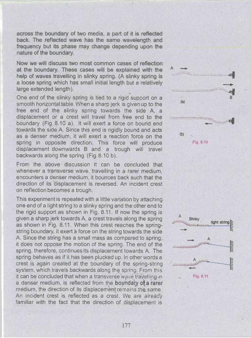
Now we will discuss two most common cases of reflection at the boundary. These cases will be explained with the help of waves travelling in slinky spring. (A slinky spring is a loose spring which has small initial length but a relatively large extended length).One end of the slinky spring is tied to a rigid support on a smooth horizontal table. When a sharp jerk is given up to the free end of the slinky spring towards the side A, a displacement or a crest will travel from free end to the boundary (Fig. 8.10 a). It will exert a force on bound end towards the side A. Since this end is rigidly bound and acts as a denser medium, it will exert a reaction force on the spring in opposite direction. This force will produce displacement downwards B and a trough will travel backwards along the spring (Fig.8.10 b).
From the above discussion it can be concluded that whenever a transverse wave, travelling in a rarer medium, encounters a denser medium, it bounces back such that the direction of its displacement is reversed. An incident crest on reflection becomes a trough.
This experiment is repeated with a little variation by attaching one end of a light string to a slinky spring and the other end to the rigid support as shown in Fig. 8.11. If now the spring is given a sharp jerk towards A, a crest travels along the spring as shown in Fig. 8.11. When this crest reaches the spring- string boundary, it exert a force on the string towards the side A. Since the string has a small mass as compared to spring, it does not oppose the motion of the spring. The end of the spring, therefore, continues its displacement towards A. The spring behaves as if it has been plucked up. In other words a crest is again created at the boundary of the spring-string system, which travels backwards along the spring. From this it can be concluded that when a transverse wave travelling in a denser medium, is reflected from the boundaty o^a rarer medium, the direction of its displacement remains ihe, same. An incident crest is reflected as a crest. We are already familiar with the fact that the direction of displacement is
.
jgM
B(a)
-•nurrmrrr'-'Trrtvrnrmr^. m
(b) ..
Fig. 8.10
SlinkyCUULUlUUJJUX., light string |
iUUJLUXLUJJUJUUL
...----------------------1
Fig. 8.11
177
reversed when there is change of 180° in the phase of vibration. So, the above conclusion can be written as follows.
i) If a transverse wave travelling in a rarer medium is incident on a denser medium, it is reflected such that it undergoes a phase change of 180°.
ii) If a transverse wave travelling in a denser medium is incident on a rarer medium, it is reflected without any change in phase.
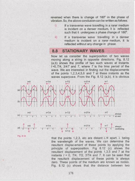
8.8 STATIONARY WAVESNow let us consider the superposition of two waves moving along a string in opposite directions. Fig. 8.12 (a,b) shows the profile of two such waves at instants t =0,7/4, 3/47 and 7, where 7 is the time period of the wave. We are interested in finding out the displacements of the points 1,2,3,4,5,6 and 7 at these instants as the waves superpose. From the Fig. 8.12 (a,b), it is obvious
t=0 t=T/4 k ! ! 1/KI ;
t=T/2 1 ; l /K i ! !
t=3T/4; i / k ; i \a
t=T
l /K ! 1 1
W h im W1 1 1V* / 1 1 1
i /1 \ 1 1 1 / 1\ 11 1 1 1 1 >»! ! ! JI 1/ 1 \ l 1 1/ 1 *
iv i/ i 1 1 V ,1 1 1 1 1 1 1 1 1 » 1 1 1 1 \ f i \ i 1 1
✓ 1 1 1 1
L ! !— r%L ! !1 \ 1 1 1 / 1 1
1 1 1! J J - W• r ■ * 1
1 1 i\ 1 /i 1 1
I / 1 V l / 1h h \ - \ - \ - h \1 / ■ 1 \ 1 Is 1 \ 1 /i 1 \ 1 /i
l \l l / 1 V 1 \/ 1 \i 1 1
1 1 \ 1 /i
t=o(C)
t=T/4*3 ”
t=T/23 5~
t=3T/4” 3 V
t=T always 7 at rest
T t=0 t t=T/4 T t=3T/4
| i t=T/2 4,
Fig. 8.12 . . .that the points 1,2,3, etc are distant X/4 apart, X being the wavelength of the waves. We can determine the resultant displacement of these points by applying the principle of superposition. Fig 8.12 (c) shows the resultant displacement of the points 1,3,5 and 7 at the instants t = 0, 7/4, 7/2, 37/4 and 7. It can be seen that the resultant displacement of these points is always zero. These points of the medium are known as nodes. Fig. 8.12 (c) shows that the distance between two
always 2 “ ~4j" " 6 " oscillating
178
consecutive nodes is A, /2. Fig. 8.12 (d) shows the resultant displacement of the points 2,4 and 6 at the instants t = 0, 7/4, 7/2, 37/4 and 7. The figure shows that these points are moving with an amplitude which is the sum of the amplitudes of the component waves. These points are known as antinodes. They are situated midway between the nodes and are also XI2 apart. The distance between a node and the next antinode is X/4. Such a pattern of nodes and anti-nodes is known as a stationary or standing wave.
Energy in a wave moves because of the motion of the particles of the medium. The nodes always remain at rest, so energy cannot flow past these points. Hence energy remains “standing” in the medium between nodes, although it alternates between potential and kinetic forms. When the antinodes are all at their extreme displacements, the energy stored is wholly potential and when they are simultaneously passing through their equilibrium positions, the energy is wholly kinetic.
An easy way to generate a stationary wave is to superpose a wave travelling down a string with its reflection travelling in opposite direction as explained in the next section.
8.9 STATIONARY WAVES IN A STRETCHED STRING
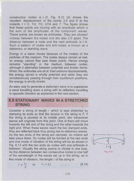
Consider a string of length / which is kept stretched by clamping its ends so that the tension in the string is F. If the string is plucked at its middle point, two transverse waves will originate from this point. One of them will move towards the left end of the string and the other towards the right end. When these waves reach the two clamped ends, they are reflected back thus giving rise to stationary waves. As the two ends of the string are clamped, no motion will take place there. So nodes will be formed at the two ends and one mode of vibration of the string will be as shown in Fig. 8.13 with the two ends as nodes with one antinode in between. Visually the string seems to vibrate in one loop. As the distance between two consecutive nodes is one half of the wavelength of the waves set up in the string, so in this mode of vibration, the length / of the string is
/ = h . or * 1 = 2 / (8.14)2
l -
Fig. 8.13
179

where X1 is the wavelength of the waves set up in this mode.The speed v of the waves in the string depends upon the tension F of the string and m, the mass per unit length of
the string. It is given by v =
Knowing the speed v and wavelength the frequency f1 of the waves is given by
Substituting the value of v,
Thus in the first mode of vibration shown in Fig. 8.13, waves of frequency f1 only will be set up in the given string.
If the same string is plucked from one quarter of its length, again stationary waves will be set up with nodes and antinodes as shown in Fig. 8.14. Note that now the string vibrates in two loops. This particular configuration of nodes and antinodes has developed because the string was plucked from the position of an antinode. As the distance between two consecutive nodes is half the wavelength, so the Fig. 8.14 shows that the length / of string is equal to the wavelength of the waves set up in this mode. If ?,2is the measure of wavelength of these waves, then,
X2 = l (8.18)
A comparison of this equation with Eq. 8.14 shows the wavelength in this case is half of that in the first case.
Eq. 8.16 shows that the speed of waves depends upon the tension and mass per unit length of the string. It is independent of the point from where the string is plucked to generate the waves. So the speed v of the waves will be same in two cases.
If f2 is frequency of vibration of string in its second mode, then by Eq. 8.2
v = f 2xX 2 = f 2 l or f2= j . ( 8 . 1 9 )
Comparing it with Eq. 8.16, we get
fi = ~ J ~ 2 l \ m
(8.16)
(8.17)
£ (8.15)
180

f2 = 2 f t
Thus when the string vibrates in two loops, its frequency becomes dogble than when it vibrates in one loop.
Similarly by plucking the string properly, it can be made to vibrate in 3 loops, with nodes and antinodes as shown in Fig. 8.15.
In this case the frequency of waves will be ft = 3 ft and the wavelength will be equal to 2113. Thus we can say that if the' string is made to vibrate in n loops, the frequency of stationary waves set up on the string will be
fn = n f t .......................... (8.20)
and the wavelength
K=-l (8.21)n
It is clear that as the string vibrates in more and more loops, its frequency goes on increasing and the wavelength gets correspondingly shorter. However the product of the frequency and wavelength is always equal to v, the speed of waves.
The above discussion, clearly establishes that the stationary waves have a discrete set of frequencies ft, 2ft,3ft ......., nft which is known as harmonic series. Thefundamental frequency ft corresponds to the first harmonic, the frequency ft - 2 ft corresponds to the second harmonic and so on. The stationary waves can be set up on the string only with the frequencies of harmonic series determined by the tension, length and mass per unit length of the string. Waves not in harmonic series are quickly damped out.
The frequency of a string on a musical instrument can be changed either by varying the tension or by changing the length. For example, the tension in guitar and violin strings is varied by tightening the pegs on the neck of the instrument. Once the instrument is tuned, the musicians vary the frequency by moving their fingers along the neck, thereby changing the length of the vibrating portion of the string.
181
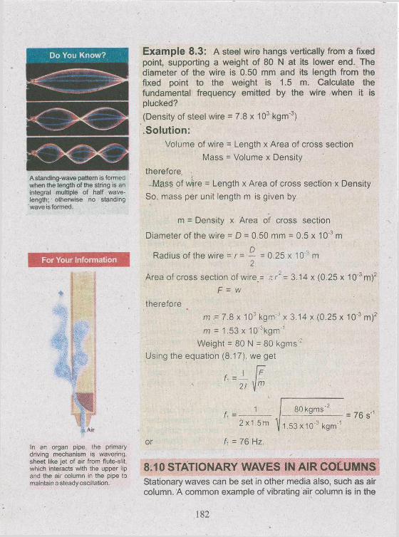
A standing-wave pattern is formed when the length of the string is an integral multiple of half wavelength; otherwise no standing wave is formed.
For Your Information
In an organ pipe, the primary driving mechanism is wavering, sheet like jet of air from flute-slit, which interacts with the upper lip and the air column in the pipe to maintain a steady oscillation.
Example 8.3: A steel wire hangs vertically from a fixed point, supporting a weight of 80 N at its lower end. The diameter of the w ire is 0.50 mm and its length from the fixed point to the weight is 1.5 m. Calculate the fundamental frequency emitted by the wire when it is plucked?
(Density of steel wire = 7.8 x 10³ kgm '3)
Solution:Volume of wire = Length x Area of cross section
Mass = Volume x Density
therefore-M ass of wljre = Length x Area of cross section x Density
So. mass per unit length m is given by
m = Density x Area of cross section
Diameter of the wire = D = 0.50 mm = 0.5 x 10'3 m
Radius o f the wire = r = — = 0.25 x 10'3 m 2
Area of cross section of wire = n r 2 = 3.14 x (0.25 x 10‘3m)2
F = w
therefore
m •= 7.8 x 10³ kgm ' x 3.14 x (0.25 x 10'3 m)2
m - 1.53 x lO ^kg m '1 W eight = 80 N = 80 kg m s '
Using the equation (8.17). we get
21
U =- 1
or
2 x1.5m
U = 76 Hz.
80 kgms'
1.53X10'3 kgm '= 76 s*
8.10 STATIONARY WAVES IN AIR COLUMNSStationary waves can be set in other media also, such as air column. A common example of vibrating air column is in the
182
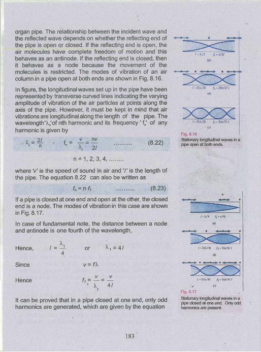
organ pipe. The relationship between the incident wave and the reflected wave depends on whether the reflecting end of the pipe is open or closed. If the reflecting end is open, the air molecules have complete freedom of motion and this behaves as an antinode. If the reflecting end is closed, then it behaves as a node because the movement of the molecules is restricted. The modes of vibration of an air column in a pipe open at both ends are shown in Fig. 8.16.
In figure, the longitudinal waves set up in the pipe have been represented by transverse curved lines indicating the varying amplitude of vibration of the air particles at points along the axis of the pipe. However, it must be kept in mind that air vibrations are longitudinal along the length of the pipe. The wavelength'A.n'of nth harmonic and its frequency ' fn' of any harmonic is given by
x = f , f„ = (8.22)n \ 21
n = 1, 2, 3 ,4 , .........
where V is the speed of sound in air and is the length of the pipe. The equation 8.22 can also be written as
fn = n U (8.23)
If a pipe is closed at one end and open at the other, the closed end is a node. The modes of vibration in this case are shown in Fig. 8.17.
In case of fundamental note, the distance between a node and antinode is one fourth of the wavelength,
Hence, / = — 4
Since
Hence
or
v = fX
^ 1 = 4 1
It can be proved that in a pipe closed at one end, only odd harmonics are generated, which are given by the equation
/ -)7 2 / ,-e /2 /<•)
" X T “X TI - 2('k/2) /,-2 (P /2 /)
<tt
/ - 3(X/2) / s -3(o/2 /)<r>
Fig. 8.16 Stationary longitudinal waves in a pipe open at both ends.
I • 3(A/4) /,-3 (0 /4 /)<M
/ - 5(31/4) f3- 5(o/4/)✓ to
Fig. 8.17Stationary longitudinal waves in a pipe dosed at one end. Only odd harmonics are present
183
Echolocation allows dolphins to detect small differences in the shape, size and thickness of objects.
rw _ . .
f „ = — (8.24)4/
where n = 1, 3, 5,
This shows that the pipe, which is open at both ends, is richer in harmonics.
Example 8.4: A pipe has a length of 1 m. Determine the frequencies of the fundamental and the first two harmonics(a) if the pipe is open at both ends and (b) if the pipe is closed at one end.
(Speed of sound in air = 340 ms'1)
Solution:
, . nv 1 x 340ms'1 . «a) fy = — = -----------------= 170 s - 170 Hz
21 2 x 1 m
f2 = 2 fj = 2 x 170 Hz = 340 Hz
and h = 3 fy = 3 x 170 Hz = 510 Hz
nv 1x340ms'1 .b fy = — = -----------------= 85 s 1 = 85 Hz
4/ 4 xim
In this case only odd harmonics are present, so
h = 3 fi = 3 x 85 Hz = 255 Hz
and f5 = 5 fy = 5 x 85 Hz = 425 Hz
8.11 DOPPLER EFFECTAn important phenomenon observed in waves is the Doppler effect. This effect shows that if there is some relative motion between the source of waves and the observer, an apparent change in frequency of the waves is observed.
This effect was observed by Johann Doppler while he was observing the frequency of light emitted from distant stars. In some cases, the frequency of light emitted from a star was found to be slightly different from that emitted from a similar source on the Earth. He found that the change in
184

frequency of light depends on the motion of star relative to the Earth.
This effect can be observed with sound waves also. When an observer is standing on a railway platform, the pitch of the whistle of an approaching locomotive is heard to be higher. But when the same locomotive moves away, the pitch of the whistle becomes lower.
The change in the frequency due to Doppler effect can be calculated easily if the relative motion between the source and the observer is along a straight line joining them. Suppose v is the velocity of the sound in the medium and the source emits a sound of frequency f and wavelength X . If both the source and the observer are stationary, then the
vwaves received by the observer in one second are f = —. IfAan observer A moves towards the source with a velocity uQ (Fig. 8.18), the relative velocity of the waves and the observer is increased to {v + u 0). Then the number of waves received in one second or modified frequency fA is
v+ u— 2-
vPutting the value of X = —, the above equation becomes
f* = fv+u
(8.25)
For an observer B receding from the source (Fig. 8.19), the relative velocity of the waves and the observer is diminished to {v - u0). Thus the observer receives waves at a reduced rate. Hence, the number of waves received in
v - uone second in this case is
If the modified frequency, which the observer hears, is fB then
Fig. 8.18
An observer moving with velocity uD towards a stationary source hears a frequency fA that is greater than the source frequency.
Fig. 8.19
(An observer moving with velocity u0 jaway from stationary source hears a /frequency fB that is smaller than the I source frequency.
185
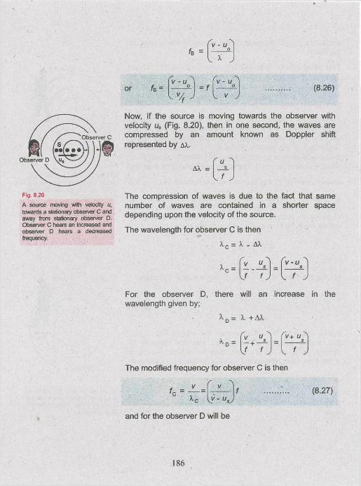
Fig. 8.20A source moving with velocity u, towards a stationary observer C and away from stationary observer D. Observer C hears an increased and observer D hears a decreased frequency.
Now, if the source is moving towards the observer with velocity us (Fig. 8.20), then in one second, the waves are compressed by an amount known as Doppler shift represented by a*,.
A A . =
The compression of waves is due to the fact that same number of waves are contained in a shorter space depending upon the velocity of the source.
The wavelength for observer C is then
x c = x - AX
x c =
wavelength given by;
a.d -
v - u sI f f J I f J
will an increase
X + AX
r , +v rv+
L f J
The modified frequency for observer C is then
V- u, (8.27)
and for the observer D will be
f ° ~ Y ~D V + U C(8.28)
This means that the observed frequency increases when the source is moving towards the observer and decreases when source is moving away from the observer.
Example 8.5: A train is approaching a station at 90 kmh'1 sounding a whistle of frequency 1000 Hz. What will be the apparent frequency of the whistle as heard by a listener sitting on the platform? What wiff be the apparent frequency heard by the same listener if the train moves away from the station with the same speed?
(speed of sound = 340ms )
Solution:
Frequency of source = f0 = 1000 Hz
Speed of sound = 340 ms'1
Speed of train = us = 90 kmh'1 = 25 ms'1
When train is approaching towards the listener, then using the relation
f ' =V — U0V S j
Do You Know?
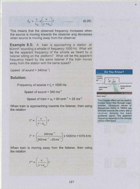
blood vesselThe Doppler effect can be used to monitor blood flow through major arteries. Ultrasound waves of frequencies 5MHz to 10MHz are directed towards the artery and a rece iver detects the back scattered signal. The apparent frequency depends on the velocity of flow of the blood.
V =340 ms'
,340 m s '1 -25 ms"1X1000 Hz = 1079.4 Hz
When train is moving away from the listener, then using the relation
r =v + u
187

M c f -Planeieceding
f iw CJ J
Plane approaching
A frequency shift is used in a radar to detect the motion of an aeroplane
Stationery star
♦
f " =
Star receding
(b)
Star approaching
*
(c)
340 ms'
340 m s '1 + 25 m s '1x1000 Hz = 931.5 Hz
Applications of Doppler EffectDoppler effect is also applicable to electromagnetic waves. One of its important applications is the radar system, which uses radio waves to determine the elevation and speed of an aeroplane. Radar is a device, which transmits and receives radio waves. If an aeroplane approaches towards the radar, then the wavelength of the wave reflected from aeroplane would be shorter and if it moves away, then the wavelength would be larger as shown in Fig. 8.21. Similarly speed of satellites moving around the Earth can also be determined by the same principle.
Sonar is an acronym derived from "Sound navigation and ranging". The general name for sonic or ultrasonic underwater echo-ranging and echo-sounding system. Sonar is the name of a technique for detecting the presence of objects underwater by acoustical echo.
In Sonar, "Doppler detection" relies upon the relative speed of the target and the detector to provide an indication of the target speed. It employs the Doppler effect, in which an apparent change in frequency occurs when the source and the observer are in relative motion to one another. Its known military applications include the detection and location of submarines, control of antisubmarine weapons, mine hunting and depth measurement of sea.
Astronomers use the Doppler effect to calculate the speeds of distant stars and galaxies. By comparing the line spectrum of light from the star with light from a laboratory source, the Doppler shift of the star's light can be measured. Then the speed of the star can be calculated.
Stars moving towards the Earth show a blue shift. This is because the wavelength of light emitted by the star are shorter than if the star had been at rest. So, the spectrum is shifted towards shorter wavelength, i.e., to the blue end of the spectrum (Fig. 8.22).
Fig. 8.22
188

Stars moving away from the Earth show a red shift. The emitted waves have a longer wavelength than if the star had been at rest. So the spectrum is shifted towards longer wavelength, i.e., towards the red end of the spectrum. Astronomers have also discovered that all the distant galaxies are moving away from us and by measuring their red shifts, they have estimated their speeds.
Another important application of the Doppler shift using electromagnetic waves is the radar speed trap. Microwaves are emitted from a transmitter in short bursts. Each burst is reflected off by any car in the path of microwaves in between sending out bursts. The transmitter is opened to detect reflected microwaves. If the reflection is caused by a moving obstacle, the reflected microwaves are Doppler shifted. By measuring the Doppler shift, the speed at which the car moves is calculated by computer programme.
m m ®• Waves carry energy and this energy is carried out by a disturbance, which spreads
out from the source.
• If the particles of the medium vibrate perpendicular to the direction of propagation of the wave, then such wave is called transverse wave, e.g. light waves.
• If the particle of the medium vibrate parallel to the direction of propagation of the wave, then such wave is called longitudinal wave, e.g. sound waves.
• If a particle of the medium is simultaneously acted upon by two waves, then the resultant displacement of the particle is the algebraic sum of their individual displacements. This is called principle of superposition.
• When two waves meet each other in a medium then at some points they reinforce the effect of each other and at some other points they cancel each other's effect. This phenomenon is called interference.
• The periodic variations of sound between maximum and minimum loudness are called beats.
• Stationary waves are produced in a medium, when two identical waves travelling in opposite directions interfere in that medium
• The apparent change in the pitch of sound caused by the relative motion of either the source of sound or the listener is called Doppler effect.
Bats navigate and find food by echo location.
189
8.1 What features do longitudinal waves have in common with transverse waves?
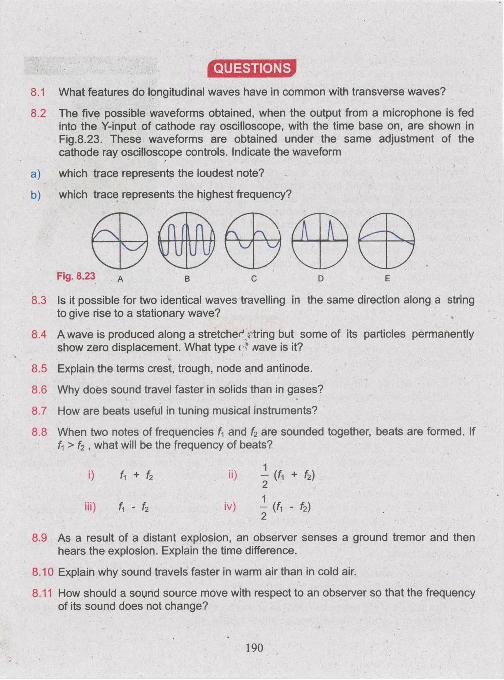
8.2 The five possible waveforms obtained, when the output from a microphone is fedinto the Y-input of cathode ray oscilloscope, with the time base on, are shown in Fig.8.23. These waveforms are obtained under the same adjustment of the cathode ray oscilloscope controls. Indicate the waveform
a) which trace represents the loudest note?
b) which trace represents the highest frequency?
Fig. 8.23 a B C D E
8.3 Is it possible for two identical waves travelling in the same direction along a string to give rise to a stationary wave?
8.4 A wave is produced along a stretched string but some of its particles permanently show zero displacement. What type < ■* yvave is it?
8.5 Explain the terms crest, trough, node and antinode.
8.6 Why does sound travel faster in solids than in gases?
8.7 How are beats useful in tuning musical instruments?
8.8 When two notes of frequencies U and f2 are sounded together, beats are formed. IfU > f2 , what will be the frequency of beats?
i) fi + h ii) - (fi + fi)2
iii) f, - f2 iv) - (f, - f2)2
8.9 As a result of a distant explosion, an observer senses a ground tremor and then hears the explosion. Explain the time difference.
8.10 Explain why sound travels faster in warm air than in cold air.
8.11 How should a sound source move with respect to an observer so that the frequencyof its sound does not change?

NUMERICAL PROBLEMS
8.1 The wavelength of the signals from a radio transmitter is 1500 m and the frequency is 200 kHz. What is the wavelength for a transmitter operating at 1000 kHz and with what speed the radio waves travel?
(Ans: 300 m, 3 x 10⁸ ms'1)8.2 Two speakers are arranged as shown in Fig. 8.24. The distance between them is 3 m
and they emit a constant tone of 344 Hz. A microphone P is moved along a line parallel to and 4.00 m from the line connecting the two speakers. It is found that tone of maximum loudness is heard and displayed on the CRO when microphone is on the centre of the line and directly opposite each speakers. Calculate the speed of sound.
Fig. 8.24
(Ans: 344 ms'1)8.3 A stationary wave is established in a string which is 120 cm long and fixed at both
ends. The string vibrates in four segments, at a frequency of 120 Hz. Determine its wavelength and the fundamental frequency?
(Ans: 0.6 m, 30 Hz)8.4 The frequency of the note emitted by a stretched string is 300 Hz. What will be the
frequency of this note when;(a) the length of the wave is reduced by one-third without changing the tension.(b) the tension is increased by one-third without changing the length of the wire.
(Ans: 450 Hz, 346 Hz)8.5 An organ pipe has a length of 50 cm. Find the frequency of its fundamental note
and the next harmonic when it is(a) open at both ends.(b) closed at one end.
(Speed of sound = 350 ms'1)[Ans: (a) 350 Hz, 700 Hz, (b) 175 Hz, 525 Hz]
191
8.6 A church organ consists of pipes, each open at one end, of different lengths. The minimum length is 30 mm and the longest is 4 m. Calculate the frequency range of the fundamental notes.(Speed of sound = 340 ms*1)
(Ans: 21 Hz to 2833 Hz)8.7 Two tuning forks exhibit beats at a beat frequency of 3 Hz. The frequency of one
fork is 256 Hz. Its frequency is then lowered slightly by adding a bit of wax to one of its prong. The two forks then exhibit a beat frequency of 1 Hz. Determine the frequency of the second tuning fork.
(Ans: 253 Hz)8.8 Two cars P and Q are travelling along a motorway in the same direction. The leading
car P travels at a steady speed of 12 ms'1; the other car Q, travelling at a steady speed of 20 ms'1, sound its horn to emit a steady note which P's driver estimates, has a frequency of 830 Hz. What frequency does Q's own driver hear?(Speed of sound = 340 ms*1)
(Ans: 810 Hz)
8.9 A train sounds its horn before it sets off from the station and an observer waiting on the plateform estimates its frequency at 1200 Hz. The train then moves off and accelerates steadily. Fifty seconds after departure, the driver sounds the horn again and the plateform observer estimates the frequency at 1140 Hz. Calculate the train speed 50 s after departure. How far from the station is the train after 50 s?(Speed of sound = 340 ms'1)
(Ans: 17.9 ms'1, 448 m)
8.10 The absorption spectrum of faint galaxy is measured and the wavelength of one of the lines identified as the Calcium a line is found to be 478 nm. The same line has a wavelength of 397 nm when measured in a laboratory.
a) Is the galaxy moving towards or away from the Earth?
b) | Calculate the speed of the galaxy relative to Earth.
(Speed of light = 3.0 x 10⁸ ms'1)
[Ans: (a) away from the Earth, (b) 6.1 x 10⁷ ms'1]
Related Documents