7SR11 & 7SR12 Performance Specification The copyright and other intellectual property rights in this document, and in any model or article produced from it (and including any registered or unregistered design rights) are the property of Siemens Protection Devices Limited. No part of this document shall be reproduced or modified or stored in another form, in any data retrieval system, without the permission of Siemens Protection Devices Limited, nor shall any model or article be reproduced from this document unless Siemens Protection Devices Limited consent. While the information and guidance given in this document is believed to be correct, no liability shall be accepted for any loss or damage caused by any error or omission, whether such error or omission is the result of negligence or any other cause. Any and all such liability is disclaimed. ©2012 Siemens Protection Devices Limited 7SR11 and 7SR12 Performance Specification Document Release History This document is issue 2012/02. The list of revisions up to and including this issue is: 2012/02 AC auxiliary power supply added 2012/01 Software Maintenance 2011/06 Software Maintenance 2010/04 Amendments following PLM review 2010/02 Reformat due to rebrand 2009/09 Revised format 2009/04 First issue Software Revision History 2012/01 7SR11 2436H80003 R2a-2a 7SR12 2436H80004 R2a-2a Software Maintenance 2011/06 7SR11 2436H80003 R2-2 7SR12 2436H80004 R2-2 Software Maintenance 2009/04 7SR11 2436H80003 R1g-1c First Release 7SR12 2436H80004 R1g-1c

Welcome message from author
This document is posted to help you gain knowledge. Please leave a comment to let me know what you think about it! Share it to your friends and learn new things together.
Transcript

7SR11 & 7SR12 Performance Specification
The copyright and other intellectual property rights in this document, and in any model or article produced from it (and including any registered or unregistered design rights) are the property of Siemens Protection Devices Limited. No part of this document shall be reproduced or modified or stored in another form, in any data retrieval system, without the permission of Siemens Protection Devices Limited, nor shall any model or article be reproduced from this document unless Siemens Protection Devices Limited consent. While the information and guidance given in this document is believed to be correct, no liability shall be accepted for any loss or damage caused by any error or omission, whether such error or omission is the result of negligence or any other cause. Any and all such liability is disclaimed. ©2012 Siemens Protection Devices Limited
7SR11 and 7SR12 Performance Specification
Document Release History This document is issue 2012/02. The list of revisions up to and including this issue is:
2012/02 AC auxiliary power supply added
2012/01 Software Maintenance
2011/06 Software Maintenance
2010/04 Amendments following PLM review
2010/02 Reformat due to rebrand
2009/09 Revised format
2009/04 First issue
Software Revision History
2012/01 7SR11 2436H80003 R2a-2a
7SR12 2436H80004 R2a-2a
Software Maintenance
2011/06 7SR11 2436H80003 R2-2
7SR12 2436H80004 R2-2
Software Maintenance
2009/04 7SR11 2436H80003 R1g-1c First Release
7SR12 2436H80004 R1g-1c

7SR11 & 7SR12 Performance Specification
Contents
Section 1: Common Functions ................................................................................................................................. 5 1.1 General ................................................................................................................................................... 5
1.1.1 CE Conformity........................................................................................................................... 5 1.1.2 Reference ................................................................................................................................. 5 1.1.3 Dimensions ............................................................................................................................... 5 1.1.4 Weights ..................................................................................................................................... 5
1.2 Energising Quantities .............................................................................................................................. 6 1.2.1 Auxiliary Power Supply ............................................................................................................. 6 1.2.2 AC Analogue Current ................................................................................................................ 7 1.2.3 AC Analogue Voltage................................................................................................................ 7 1.2.4 Binary (Digital) Outputs ............................................................................................................. 8 1.2.5 Binary (Digital) Inputs................................................................................................................ 8
1.3 Functional performance ........................................................................................................................ 10 1.3.1 Instrumentation ....................................................................................................................... 10 1.3.2 USB 2.0 Data Communication Interface ................................................................................. 10 1.3.3 RS485 Data Communication Interface.................................................................................... 10 1.3.4 Real Time Clock...................................................................................................................... 10
1.4 Environmental Performance.................................................................................................................. 11 1.4.1 General ................................................................................................................................... 11 1.4.2 Emissions................................................................................................................................ 11 1.4.3 Immunity ................................................................................................................................. 12 1.4.4 Mechanical.............................................................................................................................. 13
Section 2: Protection Functions ............................................................................................................................. 15 2.1 27/59 Under/over voltage...................................................................................................................... 15
2.1.1 Reference ............................................................................................................................... 15 2.1.2 Operate and Reset Level ........................................................................................................ 15 2.1.3 Operate and Reset Time......................................................................................................... 15
2.2 37 Undercurrent .................................................................................................................................... 16 2.2.1 Reference ............................................................................................................................... 16 2.2.2 Operate and Reset Level ........................................................................................................ 16 2.2.3 Operate and Reset Time......................................................................................................... 16
2.3 46NPS Negative Phase Sequence Overcurrent .................................................................................. 17 2.3.1 Reference (46DT) ................................................................................................................... 17 2.3.2 Operate and Reset Level (46DT) ............................................................................................ 17 2.3.3 Operate and Reset Time (46DT)............................................................................................. 17 2.3.4 Reference (46IT)..................................................................................................................... 17 2.3.5 Operate and Reset Level (46IT).............................................................................................. 17 2.3.6 Operate and Reset Time (46IT) .............................................................................................. 18
2.4 47 Negative Phase Sequence Voltage................................................................................................. 19 2.4.1 Reference (47) ........................................................................................................................ 19 2.4.2 Operate and Reset Level (47)................................................................................................. 19 2.4.3 Operate and Reset Time (47) ................................................................................................. 19
2.5 49 Thermal Overload ............................................................................................................................ 20 2.5.1 Reference ............................................................................................................................... 20 2.5.2 Operate and Reset Level ........................................................................................................ 20 2.5.3 Operate and Reset Time......................................................................................................... 20
2.6 50 Instantaneous Overcurrent............................................................................................................... 22 2.6.1 Reference ............................................................................................................................... 22 2.6.2 Operate and Reset Level ........................................................................................................ 22 2.6.3 Operate and Reset Time......................................................................................................... 22
2.7 50G Instantaneous Measured Earth Fault ............................................................................................ 23 2.7.1 Reference ............................................................................................................................... 23 2.7.2 Operate and Reset Level ........................................................................................................ 23 2.7.3 Operate and Reset Time......................................................................................................... 23
2.8 50N Instantaneous Derived Earth Fault ................................................................................................ 24 2.8.1 Reference ............................................................................................................................... 24 2.8.2 Operate and Reset Level ........................................................................................................ 24 2.8.3 Operate and Reset Time......................................................................................................... 24
©2012 Siemens Protection Devices Limited Chapter 3 Page 2 of 49

7SR11 & 7SR12 Performance Specification
2.9 50SEF Instantaneous Sensitive Earth Fault.......................................................................................... 25 2.9.1 Reference ............................................................................................................................... 25 2.9.2 Operate and Reset Level ........................................................................................................ 25 2.9.3 Operate and Reset Time......................................................................................................... 25
2.10 51 Time Delayed Overcurrent .............................................................................................................. 26 2.10.1 Reference ............................................................................................................................... 26 2.10.2 Operate and Reset Level ........................................................................................................ 26 2.10.3 Operate and Reset Time......................................................................................................... 26
2.11 51G Time Delayed Measured Earth Fault............................................................................................. 32 2.11.1 Reference ............................................................................................................................... 32 2.11.2 Operate and Reset Level ........................................................................................................ 32 2.11.3 Operate and Reset Time......................................................................................................... 32
2.12 51N Time Delayed Derived Earth Fault................................................................................................. 34 2.12.1 Reference ............................................................................................................................... 34 2.12.2 Operate and Reset Level ........................................................................................................ 34 2.12.3 Operate and Reset Time......................................................................................................... 34
2.13 51SEF Time Delayed Sensitive Earth Fault .......................................................................................... 36 2.13.1 Reference ............................................................................................................................... 36 2.13.2 Operate and Reset Level ........................................................................................................ 36 2.13.3 Operate and Reset Time......................................................................................................... 36
2.14 51V Voltage Controlled Overcurrent ..................................................................................................... 38 2.14.1 Reference ............................................................................................................................... 38 2.14.2 Operate and Reset Level ........................................................................................................ 38
2.15 59N Neutral Voltage Displacement ....................................................................................................... 39 2.15.1 Reference (59NDT)................................................................................................................. 39 2.15.2 Operate and Reset Level (59NDT) ......................................................................................... 39 2.15.3 Operate and Reset Time (59NDT) .......................................................................................... 39 2.15.4 Reference (59NIT) .................................................................................................................. 39 2.15.5 Operate and Reset Level (59NIT) ........................................................................................... 39
2.16 64H Restricted Earth Fault Protection................................................................................................... 41 2.16.1 Reference ............................................................................................................................... 41 2.16.2 Operate and Reset Level ........................................................................................................ 41 2.16.3 Operate and Reset Time......................................................................................................... 41
2.17 67/67N Directional Overcurrent & Earth Fault...................................................................................... 42 2.17.1 Reference ............................................................................................................................... 42 2.17.2 Operate Angle......................................................................................................................... 42 2.17.3 Operate Threshold .................................................................................................................. 42 2.17.4 Operate and Reset Time......................................................................................................... 42
2.18 Directional SEF - Wattmetric................................................................................................................. 43 2.18.1 Reference ............................................................................................................................... 43 2.18.2 Operate and Reset Level ........................................................................................................ 43 2.18.3 Operate and Reset Time......................................................................................................... 43
2.19 81 Under/over frequency....................................................................................................................... 44 2.19.1 Reference ............................................................................................................................... 44 2.19.2 Operate and Reset Level ........................................................................................................ 44 2.19.3 Operate and Reset Time......................................................................................................... 44
Section 3: Supervision Functions........................................................................................................................... 45 3.1 46BC Broken Conductor ....................................................................................................................... 45
3.1.1 Reference ............................................................................................................................... 45 3.1.2 Operate and Reset Level ........................................................................................................ 45 3.1.3 Operate and Reset Time......................................................................................................... 45
3.2 50BF Circuit Breaker Fail ...................................................................................................................... 46 3.2.1 Reference ............................................................................................................................... 46 3.2.2 Operate and Reset Level ........................................................................................................ 46 3.2.3 Operate and Reset Time......................................................................................................... 46
3.3 60CTS & 60CTS-I Current Transformer Supervision ............................................................................ 47 3.3.1 Reference ............................................................................................................................... 47 3.3.2 Current & Voltage Threshold................................................................................................... 47 3.3.3 Operate and Reset Time......................................................................................................... 47
3.4 60VTS Voltage Transformer Supervision.............................................................................................. 48 3.4.1 Reference ............................................................................................................................... 48 3.4.2 Operate and Reset Level ........................................................................................................ 48 3.4.3 Operate and Reset Time......................................................................................................... 48
©2012 Siemens Protection Devices Limited Chapter 3 Page 3 of 49

7SR11 & 7SR12 Performance Specification
3.5 74TCS & 74CCS Trip & Close Circuit Supervision ............................................................................... 49 3.5.1 Reference ............................................................................................................................... 49 3.5.2 Operate and Reset Time......................................................................................................... 49
3.6 81HBL2 Inrush Detector....................................................................................................................... 49 3.6.1 Reference ............................................................................................................................... 49 3.6.2 Operate and Reset Time......................................................................................................... 49
List of Figures Figure 1.2-1 Binary Input Configurations Providing Compliance with EATS 48-4 Classes
ESI 1 and ESI 2 ...................................................................................................................9 Figure 2.5-1 Thermal Overload Protection Curves ................................................................................21 Figure 2.10-1 IEC IDMTL Curves (Time Multiplier=1) ......................................................................28 Figure 2.10-2 ANSI IDMTL Operate Curves (Time Multiplier=1) .....................................................29 Figure 2.10-3 ANSI Reset Curves (Time Multiplier=1) .....................................................................30 Figure 2.10-4 IEC Reset Curves (Time Multiplier=1) .......................................................................31
©2012 Siemens Protection Devices Limited Chapter 3 Page 4 of 49

7SR11 & 7SR12 Performance Specification
Section 1: Common Functions
1.1 General 1.1.1 CE Conformity
This product is CE compliant to relevant EU directives.
1.1.2 Reference This product complies with IEC 60255-3, IEC 60255-6, IEC60255-11, IEC 60255-12 and IEC61000-4-8.
1.1.2.1 Accuracy Reference Conditions
This product has been tested under the following conditions, unless specifically stated otherwise.
Parameter Value
Auxiliary supply nominal
Frequency nominal
Ambient temperature 20 °C
1.1.3 Dimensions Parameter Value
Width E4 case 103.5 mm
Height 177 mm
Depth behind panel (including clearance for wiring and fibre) 241.5 mm
Projection (from front of panel) 31 mm
See appropriate case outline and panel drilling drawing, as specified in Diagrams and Parameters of the Installation section, for complete dimensional specifications.
1.1.4 Weights Parameter Value
7SR1101, E4 case 2.7 kg
7SR1102, E4 case 3.2 kg
7SR1103, E4 case 3.2 kg
7SR1204, E4 case 2.7 kg
7SR1205, E4 case 3.2 kg
Net weight
7SR1206, E4 case 3.2 kg
©2012 Siemens Protection Devices Limited Chapter 3 Page 5 of 49

7SR11 & 7SR12 Performance Specification
1.2 Energising Quantities
1.2.1 Auxiliary Power Supply IEC60255-11 & EATS 48-4
Nominal Operating Range Absolute Range* Comments
24 to 60 VDC 18 to 72 VDC Low voltage PSU suitable for 24VDC, 30VDC,48VDC and 60VDC systems
80 to 250 VDC 64 to 300 VDC High Voltage PSU suitable for 115VAC, 110VDC and 220VDC systems. Vaux
115 VAC 50/60Hz 92 to 138 V rms AC
47.5-52.5/57-63Hz High Voltage PSU suitable for 115VAC,
110VDC and 220VDC systems.
*No relay operation outside of this range is permissible or implied. 1.2.1.1 Burden Attribute Value
Minimum 3.9 W User Access (back light) 5.3 W 24V DC
Maximum 8.0W Minimum 3.9W User Access (back light) 5.2 W 60V DC
Maximum 7.3W Minimum 4.0W User Access (back light) 5.5W 80V DC
Maximum 6.5W Minimum 4.2W User Access (back light) 5.4W 250V DC
Maximum 7.5W Minimum 9VA 0.5PF approx. User Access (back light) 10VA 0.5PF approx. 115V AC
Maximum 15VA 0.5PF approx.
1.2.1.2 Operational Features Attribute Value Comments
0% Dip Withstand Period 50ms
Dip Immunity Acquisition Period 5minutes Typical time after switch on to
attain claimed immunity to dips
NOTE: Dips in supply that fall below the minimum voltage for a period greater than the
0% Dip With stand Period will invoke a relay reset. During conditions of auxiliary input voltage variations which are not described (1) in section 1.4.3.1, the relay may enter a safety protection mode where a power supply shutdown occurs. This condition is designed to protect the power supply from damage as well as prevent internal relay faults from developing into dangerous situations. Once the relay has entered this safety mode, it may be necessary to reduce the auxiliary input voltage to zero volts for up to 30 seconds before re-application of the auxiliary supply will cause the relay to power up and operate normally.
(1) Using fuses as on/off switches or allowing batteries to run at very low cell voltages for extended periods and then attempting to re-charge them are examples of such auxiliary supply conditions.
©2012 Siemens Protection Devices Limited Chapter 3 Page 6 of 49

7SR11 & 7SR12 Performance Specification
1.2.2 AC Analogue Current Nominal Measuring Range In 1, 5 A Phase, Earth and SEF 80 x In fn 50, 60Hz 47.5 to 52.5Hz and 57 to 63Hz
Note. 1A and 5A nominal inputs are user selectable on each model.
1.2.2.1 Burden
Value - Phase, Earth and SEF Attribute
1A 5A AC Burden ≤ 0.1 VA ≤ 0.3 VA Input Impedance (typical) 0.05 Ω 0.01 Ω
1.2.2.2 Thermal Withstand EATS48-5 Overload Current
Phase, Earth and SEF Overload Period 1A 5A
Continuous 3.0 xIn 10 minutes 3.5 xIn 5 minutes 4.0 xIn 3 minutes 5.0 xIn 2 minutes 6.0 xIn 3 seconds 57.7A 202A 2 seconds 70.7A 247A 1 second 100A 350A 1 cycle 700A 2500A
1.2.3 AC Analogue Voltage Nominal Operating Range Vn 63.5V, 110 V 270 V fn 50, 60Hz 47.5 to 52.5Hz and 57 to 63Hz
1.2.3.1 Burden Attribute Value AC Burden - 0.02 VA @ 63.5 V , ≤ 0.06 VA @ 110 V
©2012 Siemens Protection Devices Limited Chapter 3 Page 7 of 49

7SR11 & 7SR12 Performance Specification
1.2.4 Binary (Digital) Outputs Contact rating to IEC 60255-0-2 Attribute Value Carry continuously 5A AC or DC
for 0.5 s 20A AC or DC Make and carry (L/R ≤ 40 ms and V ≤ 300 V) for 0.2 s 30A AC or DC
AC resistive 1250 VA
AC inductive 250 VA at p.f. ≤ 0.4 DC resistive 75 W
Break ( ≤ 5 A and ≤ 300 V)
DC inductive 30 W at L/R ≤ 40ms 50 W at L/R ≤ 10ms
Contact Operate / Release Time 7ms / 3ms Minimum number of operations 1000 at maximum load Minimum recommended load 0.5 W at minimum of 10mA or 5V
1.2.5 Binary (Digital) Inputs DC operation EATS48-4 Nominal Operating Range
19 VDC 17 to 320 VDC VBI
88 VDC 74 to 320 VDC
AC operation Nominal Operating Range VBI 19 VDC 92 to 138 VRMSAC
1.2.5.1 DC Performance Attribute Value
VBI = 19 V 1.5mA Maximum DC current for operation VBI = 88 V 1.5mA
Reset/Operate voltage ratio ≥ 90 %
Response time < 9ms
Response time when programmed to energise an output relay contact (i.e. includes output relay operation)
< 20ms
The binary inputs have a low minimum operate current and may be set for high speed operation. Where a binary input is both used to influence a control function (e.g. provide a tripping function) and it is considered to be susceptible to mal-operation due to capacitive currents, the external circuitry can be modified to provide immunity to such disturbances.
To comply with EATS 48-4, classes ESI 1 and ESI 2, external components / BI pick-up delays are required as shown in fig. 1-1.
To achieve immunity from AC interference, a BI pick-up delay of typically one-cycle can be applied.
©2012 Siemens Protection Devices Limited Chapter 3 Page 8 of 49

7SR11 & 7SR12 Performance Specification
Figure 1.2-1 Binary Input Configurations Providing Compliance with EATS 48-4 Classes ESI 1 and ESI 2
©2012 Siemens Protection Devices Limited Chapter 3 Page 9 of 49

7SR11 & 7SR12 Performance Specification
1.2.5.2 AC Performance Attribute Value Maximum peak current for operation VBI = 19 V 1.5mA
Response time @115VRMSAC < 16ms
Response time when programmed to energise an output relay contact (i.e. includes output relay operation)
< 26ms
For AC operation the BI pick-up delay should be set to 0ms and the drop-off delay to 25ms. For AC operation wiring should be screened twisted pair for any wiring run which is greater than 10 metres in length.
1.3 Functional performance
1.3.1 Instrumentation Instrument Value Reference Typical accuracy I Current I ≥ 0.1 xIn ± 1 % In or ± 5 mA
V Voltage V ≥ 0.8 xVn ± 1 % Vn W,Var,VA Power, real and apparent V = Vn, I ≥ 0.1 xIn, pf ≥ 0.8 ± 3% Pn, where Pn = Vn x In
pf Power factor V = Vn, I ≥ 0.1 xIn, pf ≥ 0.8 ± 0.05
F Frequency F = 47.5 to 52.5Hz @ 50Hz and 57 to 63Hz @60Hz ± 10mHz
1.3.2 USB 2.0 Data Communication Interface Attribute Value Physical layer Electrical Connectors USB-Type B
1.3.3 RS485 Data Communication Interface Attribute Value Physical layer Electrical Connectors 4mm Ring Crimp
1.3.4 Real Time Clock
1.3.4.1 Internal Clock
The specification below applies only while no external synchronisation signal (e.g. 60870-5-103) is being received. Attribute Value Accuracy (-10 to +55oC) ± 3.5 p.p.m
©2012 Siemens Protection Devices Limited Chapter 3 Page 10 of 49

7SR11 & 7SR12 Performance Specification
1.4 Environmental Performance 1.4.1 General
1.4.1.1 Temperature
IEC 60068-2-1/2 Type Level Operating range -10 °C to +55 °C
Storage range -25 °C to +70 °C
1.4.1.2 Humidity
IEC 60068-2-78 Type Level Operational test 56 days at 40 °C and 93 % relative humidity
1.4.1.3 Transient Overvoltage
IEC 60255-5 Type Level Between all terminals and earth, or between any two independent circuits 5.0 kV, 1.2/50 μs 0.5j
1.4.1.4 Insulation
IEC 60255-5 Type Level Between any terminal and earth Between independent circuits
2.5 kV AC RMS for 1 min
Across normally open contacts 1.0 kV AC RMS for 1 min
1.4.1.5 IP Ratings
IEC60529 Type Level
Installed with cover on IP 5X, Category 2- Dust-protected
Installed with cover off IP 4X, 1mm probe
1.4.2 Emissions IEC 60255-25
1.4.2.1 Radiated Emissions: Enclosure Type Limits at 10 m, Quasi-peak 30 to 230 MHz 40 dB(μV/m)
230 to 1000 MHz 47 dB(μV/m)
1.4.2.2 Radiated Emissions: Conducted Limits
Type Quasi-peak Average
0.15 to 0.5 MHz 79 dB(μV) 66 dB(μV)
0.5 to 30 MHz 73 dB(μV) 60 dB(μV)
©2012 Siemens Protection Devices Limited Chapter 3 Page 11 of 49

7SR11 & 7SR12 Performance Specification
1.4.3 Immunity
1.4.3.1 Auxiliary Supply Variation IEC 60255-11
Type of Phenomena Test Specifications Duration Declared Operation
0% RV 50ms
(Claimed) Normal Operation1
40% RV 200ms Normal operation1 except where Dip falls below the relay minimum voltage then Relay Restart2
Voltage Dips
(DC auxiliary supply)
70% RV 500ms Normal operation1 except where Dip falls below the relay minimum voltage then Relay Restart2
0% RV
2.5/3 cycles
@50/60Hz (claimed)
Normal Operation1
40% RV 10/12 cycles
@50/60Hz Normal Operation1
Voltage Dips
(AC auxiliary supply)
70% RV 25/30 cycles
@50/60Hz Normal Operation1
Voltage Interruptions
(DC auxiliary supply) 0% RV 5s Relay Reset2
Voltage Interruptions
(AC auxiliary supply) 0% RV
250/300 cycles
@50/60Hz Relay Reset2
Alternating Component In DC (Ripple)
(DC auxiliary supply)
15% max and min RV Continuous Normal operation1
Max & min RV to 0V 60s Relay Reset
0V 5minutes Relay Off Gradual Shut-down/ Start-up
(DC auxiliary supply) 0V to min & max RV 60s Relay Restart2
Reversal of DC Power Supply polarity Max reversed RV 1minute
24-60 V Dc models:
No operation
80-250 V DC, 115 V AC models:
Normal Operation1
Key:
RV = Residual Voltage Test Value. Two conditions: (a) range voltage low-20% and
(b) range voltage high +20% 1 No effect on relay performance 2 Restart with no mal-operation, loss of data or relay damage
1.4.3.2 High Frequency Disturbance
IEC 60255-22-1 Type Level Common (longitudinal) mode 2.5 kV
©2012 Siemens Protection Devices Limited Chapter 3 Page 12 of 49

7SR11 & 7SR12 Performance Specification
©2012 Siemens Protection Devices Limited Chapter 3 Page 13 of 49
Type Level Series (transverse) mode 1.0 kV
1.4.3.3 Electrostatic Discharge
IEC 60255-22-2 Class 4 Type Level Variation Contact discharge 8.0 kV ≤ 5 %
1.4.3.4 Radiated Immunity
IEC 60255-22-3 Type Level 80 MHz to 1000 MHz Sweep 10 V/m 1.4GHz to 2.7GHz Sweep 10V/m 80,160,380,450,900,1850,2150 MHz Spot 10V/m
1.4.3.5 Fast Transients
IEC 60255-22-4 (2002) Class A Type Level 5/50 ns 2.5 kHz repetitive 4kV
1.4.3.6 Surge Immunity
IEC 60255-22-5 Type Level Between all terminals and earth 0.5, 1.0, 2.0, 4.0 kV Between Line to Line* 0.5, 1.0, 2.0 kV
*Note. 45ms pick up delay for DTL applied to binary inputs for DC operation. For AC operation where 0ms pick-up delay is required, screened twisted pair wiring must be used for lengths greater than 10 m.
1.4.3.7 Conducted Radio Frequency Interference
IEC 60255-22-6 Type Level 0.15 to 80 MHz 10 V
1.4.3.8 Magnetic Field with Power Frequency
IEC 6100-4-8 Level 5
100A/m, (0.126mT) continuous
1000A/m, (1.26mT) for 3s 50Hz
1.4.4 Mechanical
1.4.4.1 Vibration (Sinusoidal)
IEC 60255-21-1 Class I Type Level Variation Vibration response 0.5 gn Vibration endurance 1.0 gn
≤ 5 %
1.4.4.2 Shock and Bump
IEC 60255-21-2 Class I Type Level Variation Shock response 5 gn, 11 ms
≤ 5 %

7SR11 & 7SR12 Performance Specification
©2012 Siemens Protection Devices Limited Chapter 3 Page 14 of 49
Type Level Variation Shock withstand 15 gn, 11 ms Bump test 10 gn, 16 ms
1.4.4.3 Seismic
IEC 60255-21-3 Class I Type Level Variation
X-plane - 3.5mm displacement below crossover freq (8-9Hz) 1.0gn above Seismic response Y-plane - 1.5mm displacement below crossover freq (8-9Hz) 0.5gn above
≤ 5 %
1.4.4.4 Mechanical Classification Type Level Durability > 106 operations

7SR11 & 7SR12 Performance Specification
Section 2: Protection Functions 2.1 27/59 Under/over voltage
2.1.1 Reference Parameter Value Vs Setting 5, 5.5…200V
hyst Hysteresis setting 0, 0.1… 80.0%
td Delay setting 0.00, 0.01…20.00, 20.50… 100, 101… 1000, 1010… 10000, 10100… 14400 s
2.1.2 Operate and Reset Level Attribute Value
Vop Operate level 100 % Vs, ± 1 % or ±0.25V
Overvoltage = (100 % - hyst) x Vop, ± 1 % or ± 0.25V Reset level
Undervoltage = (100 % + hyst) x Vop ± 1 % or ± 0.25V
Repeatability ± 1 %
-10 °C to +55 °C ≤ 5 % Variation
fnom ± 5 % ≤ 5 %
2.1.3 Operate and Reset Time Attribute Value
0 to 1.1 x Vs: 73 ms or ± 10ms Overvoltage
0 to 2.0 xVs: 63 ms or ± 10ms tbasicE Element basic operate time
Undervoltage 1.1 to 0.5 xVs: 58 ms or ± 10ms
top Operate time following delay tbasic + td, ± 1 % or ± 10ms
Repeatability ± 1 % or ± 10ms
Disengaging time < 80 ms
©2012 Siemens Protection Devices Limited Chapter 3 Page 15 of 49

7SR11 & 7SR12 Performance Specification
2.2 37 Undercurrent
2.2.1 Reference Parameter Value
Is Setting 0.05, 0.10…5.0 xIn
td Delay setting 0.00, 0.01…20.00, 20.10… 100, 101… 1000, 1010… 10000, 10100… 14400 s
2.2.2 Operate and Reset Level Attribute Value
Iop Operate level 100 % Is, ± 5 % or ± 1% In
Reset level ≤ 105 % Iop
Repeatability ± 1 %
-10 °C to +55 °C ≤ 5 % Variation
fnom ± 5 % ≤ 5 %
2.2.3 Operate and Reset Time Attribute Value
tbasic Element basic operate time 1.1 to 0.5 xIs: 35 ms or ± 10ms
top Operate time following delay tbasic + td, ± 1 % or ± 10ms
Repeatability ± 1 % or ± 10ms
Overshoot time < 40 ms
Disengaging time < 60 ms
©2012 Siemens Protection Devices Limited Chapter 3 Page 16 of 49

7SR11 & 7SR12 Performance Specification
2.3 46NPS Negative Phase Sequence Overcurrent
2.3.1 Reference (46DT) Parameter Value Is Setting 0.05, 0.06... 4.0xIn
td Delay setting 0.00, 0.01…20.00, 20.10… 100, 101… 1000, 1010… 10000, 10100… 14400 s
2.3.2 Operate and Reset Level (46DT) Attribute Value
Iop Operate level 100 % Is, ± 5 % or ± 1% In
Reset level ≥ 95 % Iop
Repeatability ± 1 %
Transient overreach (X/R ≤ 100) ≤ -5 %
-10 °C to +55 °C ≤ 5 % Variation
fnom ± 5 % ≤ 5 %
2.3.3 Operate and Reset Time (46DT) Attribute Value
0 to 2 xIs: 40 ms or ± 10ms tbasic Element basic operate time
0 to 5 xIs: 30 ms or ± 10ms
top Operate time following delay tbasic + td, ± 1 % or ± 10ms
Repeatability ± 1 % or ± 10ms
Overshoot time <40 ms
Disengaging time < 60 ms
2.3.4 Reference (46IT) Parameter Value char Characteristic setting IEC-NI, -VI, -EI, -LTI; ANSI-MI, -VI, -EI; DTL Tm Time Multiplier setting 1.0 Is Setting 0.05, 0.06… 2.5xIn
I Applied Current (for operate time) IDMTL 2 to 20 x Is
td Delay setting 0, 0.01… 20 s tres Reset setting ANSI DECAYING, 0, 1… 60 s
2.3.5 Operate and Reset Level (46IT) Attribute Value
Iop Operate level 105 % Is, ± 4 % or ± 1% In
Reset level ≥ 95 % Iop
Repeatability ± 1 %
-10 °C to +55 °C ≤ 5 % Variation
fnom ± 5 % ≤ 5 %
©2012 Siemens Protection Devices Limited Chapter 3 Page 17 of 49

7SR11 & 7SR12 Performance Specification
©2012 Siemens Protection Devices Limited Chapter 3 Page 18 of 49
2.3.6 Operate and Reset Time (46IT) Attribute Value Starter operate time (≥ 2xIs) 35 ms, ± 10ms
char = IEC-NI, IEC-VI, IEC-EI, IEC-LTI
[ ]TmKt
IsI
op ×−
=1α
, ± 5 % absolute or ± 50 ms,
for char = IEC-NI : K = 0.14, α = 0.02 IEC-VI : K = 13.5, α = 1.0 IEC-EI : K = 80.0, α = 2.0 IEC-LTI : K = 120.0, α = 1.0
char = ANSI-MI, ANSI-VI, ANSI-EI
[ ]TmBAt
PIsI
op ×⎥⎥
⎦
⎤
⎢⎢
⎣
⎡+
−=
1, ± 5 % absolute or ± 50 ms,
for char = ANSI-MI : A = 0.0515, B = 0.114, P = 0.02 ANSI-VI : A = 19.61, B = 0.491, P = 2.0 ANSI-EI : A = 28.2, B = 0.1217, P = 2.0
top Operate time
char = DTL td, ± 1 % or ± 20ms
ANSI DECAYING [ ] TmRt
IsIres ×
−=
12 , ± 5 % absolute or ± 50 ms,
for char = ANSI-MI : R = 4.85 ANSI-VI : R = 21.6 ANSI-EI : R = 29.1
IEC DECAYING
[ ] TmRtIsIres ×
−=
12 , ± 5 % absolute or ± 50 ms,
for char = IEC-NI : R = 9.7 IEC-VI : R = 43.2 IEC-EI : R = 58.2 IEC-LTI : R = 80
Reset time
tres tres, ± 1 % or ± 20ms
Repeatability ± 1 % or ± 20ms
Overshoot time < 40 ms
Disengaging time < 60 ms

7SR11 & 7SR12 Performance Specification
2.4 47 Negative Phase Sequence Voltage
2.4.1 Reference (47) Parameter Value
Vs Setting 1, 1.5… 90V
Hyst. Hysteresis 0, 0.1… 80%
td Delay setting 0.00, 0.01…20.00, 20.10… 100, 101… 1000, 1010… 10000, 10100… 14400 s
2.4.2 Operate and Reset Level (47) Attribute Value
Vop Operate level 100 % Vs, ± 2 % or ± 0.5 V
Reset level (100%-Hyst.) x Vop ± 1% or ± 0.25V
Repeatability ± 1 %
-10 °C to +55 °C ≤ 5 % Variation
fnom ± 5 % ≤ 5 %
2.4.3 Operate and Reset Time (47) Attribute Value
0V to 2.0 xVs, 80 ms or ± 20ms tbasic Element basic operate time
0V to 10 xVs, 70ms or ± 20ms
top Operate time following delay tbasic + td, ± 2 % or ± 20ms
Repeatability ± 1 % or ± 20ms
Overshoot time < 40 ms
Disengaging time < 90 ms
©2012 Siemens Protection Devices Limited Chapter 3 Page 19 of 49

7SR11 & 7SR12 Performance Specification
©2012 Siemens Protection Devices Limited Chapter 3 Page 20 of 49
2.5 49 Thermal Overload
2.5.1 Reference Parameter Value
Is Overload setting 1.0 xIn
i Applied Current (for operate time) 1.2 to 10 x Is
τ Time constant setting 1, 10, 100, 1000 min
2.5.2 Operate and Reset Level Attribute Value
Iol Overload level 100 % Is, ± 5 % or ± 1% In
Reset level ≥ 95 % Iol
Repeatability ± 1 %
-10 °C to +55 °C ≤ 5 % Variation
fnom ± 5 % ≤ 5 %
2.5.3 Operate and Reset Time Attribute Value
top Overload trip operate time ( ) ⎭⎬⎫
⎩⎨⎧
×−−
×τ= 22
2P
2
IIIln
BIkt
where IP = prior current
, ± 5 % absolute or ± 100ms,
Repeatability ± 100ms
Note:- Fastest operate time is at 10 xIs

7SR11 & 7SR12 Performance Specification
©2012 Siemens Protection Devices Limited Chapter 3 Page 21 of 49
0.1
1
10
100
1000
10000
100000
0 1 2 3 4 5 6 7 8 9Current (multiple of setting)
Time(sec)
10
τ = 1000 mins
τ = 100 mins
τ = 10 mins
τ = 1 min
Figure 2.5-1 Thermal Overload Protection Curves

7SR11 & 7SR12 Performance Specification
2.6 50 Instantaneous Overcurrent
2.6.1 Reference Parameter Value
Is Setting 0.05, 0.06… 2.5, 2.55… 50 xIn
td Delay setting 0.00, 0.01…20.00, 20.10… 100, 101… 1000, 1010… 10000, 10100… 14400 s
2.6.2 Operate and Reset Level Attribute Value
Iop Operate level 100 % Is, ± 5 % or ± 1% In
Reset level ≥ 95 % Iop
Repeatability ± 1 %
Transient overreach (X/R ≤ 100) ≤ -5 %
-10 °C to +55 °C ≤ 5 % Variation
fnom ± 5 % ≤ 5 %
2.6.3 Operate and Reset Time Attribute Value
0 to 2 xIs: 35 ms or ± 10ms tbasic Element basic operate time
0 to 5 xIs: 25 ms or ± 10ms
top Operate time following delay tbasic + td, ± 1 % or ± 10ms
Repeatability ± 1 % or ± 10ms
Overshoot time < 40 ms
Disengaging time < 50 ms
©2012 Siemens Protection Devices Limited Chapter 3 Page 22 of 49

7SR11 & 7SR12 Performance Specification
2.7 50G Instantaneous Measured Earth Fault
2.7.1 Reference Parameter Value
Is Setting 0.05, 0.06…2.5,2.55 …25.0,25.5…. 50 xIn
td Delay setting 0.00, 0.01…20.00, 20.10… 100, 101… 1000, 1010… 10000, 10100… 14400 s
2.7.2 Operate and Reset Level Attribute Value
Iop Operate level 100 % Is, ± 5 % or ± 1% In
Reset level ≥ 95 % Iop
Repeatability ± 1 %
Transient overreach (X/R ≤ 100) ≤ -5 %
-10 °C to +55 °C ≤ 5 % Variation
fnom ± 5 % ≤ 5 %
2.7.3 Operate and Reset Time Attribute Value
0 to 2 xIs: 35 ms or ± 10ms tbasic Element basic operate time
0 to 5 xIs: 25 ms or ± 10ms
top Operate time following delay tbasic + td, ± 1 % or ± 10ms
Repeatability ± 1 % or ± 10ms
Overshoot time < 40 ms
Disengaging time < 50 ms
©2012 Siemens Protection Devices Limited Chapter 3 Page 23 of 49

7SR11 & 7SR12 Performance Specification
2.8 50N Instantaneous Derived Earth Fault
2.8.1 Reference Parameter Value
Is Setting 0.05, 0.06…2.5,2.55 …25.0,25.5…. 50 xIn
td Delay setting 0.00, 0.01…20.00, 20.10… 100, 101… 1000, 1010… 10000, 10100… 14400 s
2.8.2 Operate and Reset Level Attribute Value
Iop Operate level 100 % Is, ± 5 % or ± 1% In
Reset level ≥ 95 % Iop
Repeatability ± 1 %
Transient overreach (X/R ≤ 100) ≤ -5 %
-10 °C to +55 °C ≤ 5 % Variation
fnom ± 5 % ≤ 5 %
2.8.3 Operate and Reset Time Attribute Value
0 to 2 xIs: 40 ms or ± 10ms tbasic Element basic operate time
0 to 5 xIs: 30 ms or ± 10ms
top Operate time following delay tbasic + td, ± 1 % or ± 10ms
Repeatability ± 1 % or ± 10ms
Overshoot time < 40 ms
Disengaging time < 50 ms
©2012 Siemens Protection Devices Limited Chapter 3 Page 24 of 49

7SR11 & 7SR12 Performance Specification
2.9 50SEF Instantaneous Sensitive Earth Fault
2.9.1 Reference Parameter Value
Is Setting 0.005, 0.006,0.010,0.105,… 5.0 xIn
td Delay setting 0.00, 0.01…20.00, 20.10… 100, 101… 1000, 1010… 10000, 10100… 14400 s
2.9.2 Operate and Reset Level Attribute Value
Iop Operate level 100 % Is, ± 5 % or ± 1% In
Reset level ≥ 95 % Iop or Iop - 0.1% In
Repeatability ± 1 %
Transient overreach (X/R ≤ 100) ≤ -5 %
-10 °C to +55 °C ≤ 5 %
Variation fnom ± 5 %
harmonics to fcutoff ≤ 5 %
2.9.3 Operate and Reset Time Attribute Value
0 to 2 xIs: 35 ms or ± 10ms tbasic
Element basic operate time
0 to 5 xIs: 25 ms or ± 10ms
top Operate time following delay tbasic + td, ± 1 % or ± 10mse
Repeatability ± 1 % or ± 10ms
Overshoot time < 40 ms
Disengaging time < 50 ms
Variation fnom ± 5 % ≤ 5 %
©2012 Siemens Protection Devices Limited Chapter 3 Page 25 of 49
7SR11 & 7SR12 Performance Specification
©2012 Siemens Protection Devices Limited Chapter 3 Page 26 of 49
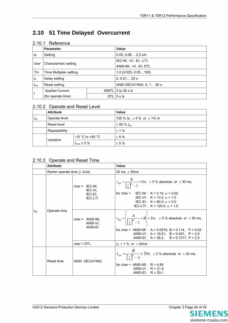
2.10 51 Time Delayed Overcurrent
2.10.1 Reference Parameter Value
Is Setting 0.05, 0.06… 2.5 xIn
char Characteristic setting IEC-NI, -VI, -EI, -LTI; ANSI-MI, -VI, -EI; DTL
Tm Time Multiplier setting 1.0 (0.025, 0.05…100)
td Delay setting 0, 0.01… 20 s
tres Reset setting ANSI DECAYING, 0, 1… 60 s
IDMTL 2 to 20 x ls I
Applied Current (for operate time) DTL 5 x Is
2.10.2 Operate and Reset Level Attribute Value
Iop Operate level 105 % Is, ± 4 % or ± 1% In
Reset level ≥ 95 % Iop
Repeatability ± 1 %
-10 °C to +55 °C ≤ 5 % Variation
fnom ± 5 % ≤ 5 %
2.10.3 Operate and Reset Time Attribute Value Starter operate time (≥ 2xIs) 20 ms, ± 20ms
char = IEC-NI, IEC-VI, IEC-EI, IEC-LTI
[ ]TmKt
IsI
op ×−
=1α
, ± 5 % absolute or ± 30 ms,
for char = IEC-NI : K = 0.14, α = 0.02 IEC-VI : K = 13.5, α = 1.0 IEC-EI : K = 80.0, α = 2.0 IEC-LTI : K = 120.0, α = 1.0
char = ANSI-MI, ANSI-VI, ANSI-EI
[ ]TmBAt
PIsI
op ×⎥⎥
⎦
⎤
⎢⎢
⎣
⎡+
−=
1, ± 5 % absolute or ± 30 ms,
for char = ANSI-MI : A = 0.0515, B = 0.114, P = 0.02 ANSI-VI : A = 19.61, B = 0.491, P = 2.0 ANSI-EI : A = 28.2, B = 0.1217, P = 2.0
top Operate time
char = DTL td, ± 1 % or ± 20ms
Reset time ANSI DECAYING [ ] TmRt
IsIres ×
−=
12 , ± 5 % absolute or ± 30 ms,
for char = ANSI-MI : R = 4.85 ANSI-VI : R = 21.6 ANSI-EI : R = 29.1

7SR11 & 7SR12 Performance Specification
©2012 Siemens Protection Devices Limited Chapter 3 Page 27 of 49
Attribute Value
IEC DECAYING
[ ] TmRtIsIres ×
−=
12 , ± 5 % absolute or ± 50 ms,
for char = IEC-NI : R = 9.7 IEC-VI : R = 43.2 IEC-EI : R = 58.2 IEC-LTI : R = 80
tres tres, ± 1 % or ± 20ms
Repeatability ± 1 % or ± 20ms
Overshoot time < 40 ms
Disengaging time < 50 ms
Figure 2.10-1 and 2.10-4 shows the operate and reset curves for the four IEC IDMTL curves with a time multiplier of 1.
Figs 2.10-2 and 2.10-3 show the ANSI operate and reset curves. These operate times apply to non-directional characteristics. Where directional control is applied then the directional element operate time should be added to give total maximum operating time.

7SR11 & 7SR12 Performance Specification
0.1
1
10
100
1000
1 10 100Current (multiples of setting)
Time(sec)
2 3 4 5 6 8 20 30 40 50 60 80
Long Time Inverse
Normal Inverse
Very Inverse
Extremely Inverse
Figure 2.10-1 IEC IDMTL Curves (Time Multiplier=1)
©2012 Siemens Protection Devices Limited Chapter 3 Page 28 of 49

7SR11 & 7SR12 Performance Specification
0.1
1
10
100
1000
1 10 100Current (multiples of setting)
Time(sec)
2 3 4 5 6 8 20 30 40 50 60 80
Moderately Inverse
Extremely Inverse
Very Inverse
Figure 2.10-2 ANSI IDMTL Operate Curves (Time Multiplier=1)
©2012 Siemens Protection Devices Limited Chapter 3 Page 29 of 49

7SR11 & 7SR12 Performance Specification
1
10
100
1000
0.1 1
Current (multiples of setting)
Time(sec)
Moderately Inverse
Extremely Inverse
Very Inverse
0.2 0.3 0.4 0.5 0.6 0.8 0.90.7
5
50
500
Figure 2.10-3 ANSI Reset Curves (Time Multiplier=1)
©2012 Siemens Protection Devices Limited Chapter 3 Page 30 of 49

7SR11 & 7SR12 Performance Specification
Figure 2.10-4 IEC Reset Curves (Time Multiplier=1)
©2012 Siemens Protection Devices Limited Chapter 3 Page 31 of 49

7SR11 & 7SR12 Performance Specification
©2012 Siemens Protection Devices Limited Chapter 3 Page 32 of 49
2.11 51G Time Delayed Measured Earth Fault
2.11.1 Reference Parameter Value
Is Setting 0.05, 0.06… 2.5 xIn
Char Characteristic setting IEC-NI, -VI, -EI, -LTI; ANSI-MI, -VI, -EI; DTL
Tm Time Multiplier setting 1.0 (0.025,0.05…100)
td Delay setting (DTL) 0, 0.01… 20 s
tres Reset setting ANSI DECAYING, 0, 1… 60 s
IDMTL 2 to 20 xIs I Applied current (for
operate time) DTL 5 xIs
2.11.2 Operate and Reset Level Attribute Value
Iop Operate level 105 % Is, ± 4 % or ± 1% In
Reset level ≥ 95 % Iop
Repeatability ± 1 %
-10 °C to +55 °C ≤ 5 % Variation
fnom ± 5 % ≤ 5 %
2.11.3 Operate and Reset Time Attribute Value Starter operate time (≥ 2xIs) 20 ms, ± 20ms
char = IEC-NI, IEC-VI, IEC-EI, IEC-LTI
[ ]TmKt
IsI
op ×−
=1α
, ± 5 % absolute or ± 30 ms,
for char = IEC-NI : K = 0.14, α = 0.02 IEC-VI : K = 13.5, α = 1.0 IEC-EI : K = 80.0, α = 2.0 IEC-LTI : K = 120.0, α = 1.0
char = ANSI-MI, ANSI-VI, ANSI-EI
[ ]TmBAt
PIsI
op ×⎥⎥
⎦
⎤
⎢⎢
⎣
⎡+
−=
1, ± 5 % absolute or ± 30 ms,
for char = ANSI-MI : A = 0.0515, B = 0.114, P = 0.02 ANSI-VI : A = 19.61, B = 0.491, P = 2.0 ANSI-EI : A = 28.2, B = 0.1217, P = 2.0
top Operate time
char = DTL td, ± 1 % or ± 20ms
Reset time ANSI DECAYING [ ] TmRt
IsIres ×
−=
12 , ± 5 % absolute or ± 30 ms,
for char = ANSI-MI : R = 4.85 ANSI-VI : R = 21.6 ANSI-EI : R = 29.1

7SR11 & 7SR12 Performance Specification
©2012 Siemens Protection Devices Limited Chapter 3 Page 33 of 49
Attribute Value
IEC DECAYING
[ ] TmRtIsIres ×
−=
12 , ± 5 % absolute or ± 50 ms,
for char = IEC-NI : R = 9.7 IEC-VI : R = 43.2 IEC-EI : R = 58.2 IEC-LTI : R = 80
tres tres, ± 1 % or ± 20ms
Repeatability ± 1 % or ± 20ms
Overshoot time < 40 ms
Disengaging time < 50 ms
Figure 2.10-1 and 2.10-4 shows the operate and reset curves for the four IEC IDMTL curves with a time multiplier of 1.
Figures 2.10-2 and 2.10-3 show the ANSI operate and reset curves. These operate times apply to non-directional characteristics. Where directional control is applied then the directional element operate time should be added to give total maximum operating time.

7SR11 & 7SR12 Performance Specification
©2012 Siemens Protection Devices Limited Chapter 3 Page 34 of 49
2.12 51N Time Delayed Derived Earth Fault
2.12.1 Reference Parameter Value
Is Setting 0.05, 0.6… 2.5 xIn
char Characteristic setting IEC-NI, -VI, -EI, -LTI; ANSI-MI, -VI, -EI; DTL
Tm Time Multiplier setting 1.0 (0.025,0.05…100)
td Delay setting 0, 0.01… 20 s
tres Reset setting ANSI DECAYING, 0, 1… 60 s
IDMTL 2 to 20 x Is I
Applied Current (for operate time) DTL 5 x Is
2.12.2 Operate and Reset Level Attribute Value
Iop Operate level 105 % Is, ± 4 % or ± 1% In
Reset level ≥ 95 % Iop
Repeatability ± 1 %
-10 °C to +55 °C ≤ 5 % Variation
fnom ± 5 % ≤ 5 %
2.12.3 Operate and Reset Time Attribute Value Starter operate time (≥ 2xIs) 30 ms, ± 20ms
char = IEC-NI, IEC-VI, IEC-EI, IEC-LTI
[ ]TmKt
IsI
op ×−
=1α
, ± 5 % absolute or ± 30 ms,
for char = IEC-NI : K = 0.14, α = 0.02 IEC-VI : K = 13.5, α = 1.0 IEC-EI : K = 80.0, α = 2.0 IEC-LTI : K = 120.0, α = 1.0
char = ANSI-MI, ANSI-VI, ANSI-EI
[ ]TmBAt
PIsI
op ×⎥⎥
⎦
⎤
⎢⎢
⎣
⎡+
−=
1, ± 5 % absolute or ± 30 ms,
for char = ANSI-MI : A = 0.0515, B = 0.114, P = 0.02 ANSI-VI : A = 19.61, B = 0.491, P = 2.0 ANSI-EI : A = 28.2, B = 0.1217, P = 2.0
top Operate time
char = DTL td, ± 1 % or ± 20ms
Reset time ANSI DECAYING [ ] TmRt
IsIres ×
−=
12 , ± 5 % absolute or ± 30 ms,
for char = ANSI-MI : R = 4.85 ANSI-VI : R = 21.6 ANSI-EI : R = 29.1

7SR11 & 7SR12 Performance Specification
©2012 Siemens Protection Devices Limited Chapter 3 Page 35 of 49
Attribute Value
IEC DECAYING
[ ] TmRtIsIres ×
−=
12 , ± 5 % absolute or ± 50 ms,
for char = IEC-NI : R = 9.7 IEC-VI : R = 43.2 IEC-EI : R = 58.2 IEC-LTI : R = 80
tres tres, ± 1 % or ± 20ms
Repeatability ± 1 % or ± 20ms
Overshoot time < 40 ms
Disengaging time < 50 ms
Figure 2.10-1 and 2.10-4 shows the operate and reset curves for the four IEC IDMTL curves with a time multiplier of 1.
Figures 2.10-2 and 2.10-3 show the ANSI operate and reset curves. These operate times apply to non-directional characteristics. Where directional control is applied then the directional element operate time should be added to give total maximum operating time.

7SR11 & 7SR12 Performance Specification
2.13 51SEF Time Delayed Sensitive Earth Fault
2.13.1 Reference Parameter Value
Is Setting 0.005, 0.006,0.010,0.105,… 5.0 xIn
char Characteristic setting IEC-NI, -VI, -EI, -LTI;
ANSI-MI, -VI, -EI; DTL
Tm Time multiplier 1.0 (0.025,0.05…100)
td Delay setting 0.00…20.00 s
tres Reset setting DECAYING, 0, 1…60 s
IDMTL 2 to 20 x Is I
Applied Current (for operate time) DTL 5 x Is
2.13.2 Operate and Reset Level Attribute Value
Iop Operate level 105 % Is, ± 4 % or ± 1% In
Reset level 95 % Iop ± 4 % or ± 1% In
Repeatability ± 1 %
-10 °C to +55 °C ≤ 5 %
Variation fnom ± 5 %
harmonics to fcutoff ≤ 5 %
2.13.3 Operate and Reset Time Attribute Value
Starter operate time 20 ms, ± 20ms
char = IEC-NI, IEC-VI, IEC-EI, IEC-LTI
[ ]TmKt
IsI
op ×−
=1α
, ± 5 % absolute or ± 30 ms,
for char = IEC-NI : K = 0.14, α = 0.02 IEC-VI : K = 13.5, α = 1.0 IEC-EI : K = 80.0, α = 2.0 IEC-LTI : K = 120.0, α = 1.0
char = ANSI-MI, ANSI-VI, ANSI-EI,
[ ]TmBAt
PIsI
op ×⎥⎥
⎦
⎤
⎢⎢
⎣
⎡+
−=
1, ± 5 % absolute or ± 30 ms,
for char = ANSI-MI : A = 0.0515, B = 0.114, P = 0.02 ANSI-VI : A = 19.61, B = 0.491, P = 2.0 ANSI-EI : A = 28.2, B = 0.1217, P = 2.0
top Operate time
char = DTL td, ± 1 % or ± tcycle
©2012 Siemens Protection Devices Limited Chapter 3 Page 36 of 49

7SR11 & 7SR12 Performance Specification
©2012 Siemens Protection Devices Limited Chapter 3 Page 37 of 49
Attribute Value
char = ANSI and tres = DECAYING
[ ] TmRtIsIres ×
−=
12 , ± 5 % absolute or ± 30 ms,
for char = ANSI-MI : R = 4.85 ANSI-VI : R = 21.6 ANSI-EI : R = 29.1
IEC DECAYING
[ ] TmRtIsIres ×
−=
12 , ± 5 % absolute or ± 50 ms,
for char = IEC-NI : R = 9.7 IEC-VI : R = 43.2 IEC-EI : R = 58.2 IEC-LTI : R = 80
Reset time
tres ≠ DECAYING tres, ± 1 % or ± 20ms
Repeatability ± 1 % or ± 20ms
Overshoot time < 40 ms
Disengaging time < 50 ms
Variation fnom ± 5 %
harmonics to fcutoff ≤ 5 %
Figure 2.10-1 shows the operate times for the four IEC IDMTL curves with a time multiplier of 1.
Figures 2.10-2 and 2.10-3 show the ANSI operate and reset curves. These operate times apply to non-directional characteristics. Where directional control is applied then the directional element operate time should be added to give total maximum operating time.

7SR11 & 7SR12 Performance Specification
2.14 51V Voltage Controlled Overcurrent
2.14.1 Reference Parameter Value
Vs Setting 60V
m multiplier 0.5
Is Setting 1xIn
2.14.2 Operate and Reset Level Attribute Value
Vop Operate level 100 % Vs, ± 1 % or ± 0.25V
Reset level ≤ 105 % Vop
Repeatability ± 1 %
-10 °C to +55 °C ≤ 5 %
Variation fnom ± 5 %
harmonics to fcutoff ≤ 5 %
Operate and Reset Time As per Phase Fault Shaped Characteristic Element (ANSI 51).
Where Pickup Level = Is for Voltage > Vs
Pickup Level = (Is x m) for Voltage < Vs
©2012 Siemens Protection Devices Limited Chapter 3 Page 38 of 49

7SR11 & 7SR12 Performance Specification
2.15 59N Neutral Voltage Displacement
2.15.1 Reference (59NDT) Parameter Value
Vs Setting 0.1 x Vn
td Delay setting 0.00, 0.01…20.00, 20.10… 100, 101… 1000, 1010… 10000, 10100… 14400 s
2.15.2 Operate and Reset Level (59NDT) Attribute Value
Vop Operate level 100 % Vs, ± 2 % or ± 0.5 V
Reset level ≥ 95 % Vop or ± 0.5 V
Repeatability ± 1 %
-10 °C to +55 °C ≤ 5 % Variation
fnom ± 5 % ≤ 5 %
2.15.3 Operate and Reset Time (59NDT) Attribute Value
0V to 1.5 xVs, 76 ms, ± 20ms tbasic Element basic operate time
0V to 10 xVs, 63 ms, ± 20ms
top Operate time following delay tbasic + td, ± 1 % or ± 20ms
Repeatability ± 1 % or ± 20ms
Overshoot time < 40 ms
Disengaging time <100 ms
2.15.4 Reference (59NIT) Parameter Value
M Multiplier setting 1
Vs Setting 1, 1.5… 100V
3Vo Applied Current (for Operate-Time) IDMTL 2 x Vs
td Delay setting 0, 0.01… 20 s
tres Reset setting 0, 1…60 s
2.15.5 Operate and Reset Level (59NIT) Attribute Value
Vop Operate level 105 % Vs, ± 2 % or ± 0.5 V
Reset level ≥ 95 % Vop or ± 0.5 V
Repeatability ± 1 %
-10 °C to +55 °C ≤ 5 % Variation
fnom ± 5 % ≤ 5 %
Operate and Reset Time (59NIT) Attribute Value
tbasic Starter operate time 65 ms, ± 20ms
3Vo Applied Current (for Operate-Time) DTL 10 x Vs
©2012 Siemens Protection Devices Limited Chapter 3 Page 39 of 49

7SR11 & 7SR12 Performance Specification
©2012 Siemens Protection Devices Limited Chapter 3 Page 40 of 49
Attribute Value
char = IDMTL [ ] 1Mt
Vs0V3op −
= , ± 5 % or ± 65 ms
top
Operate time
char = DTL td, ± 1 % or ± 40ms
char = IDMTL tres, ± 5 % or ± 65ms Reset Time
char = DTL tres, ± 1 % or ± 40ms
Repeatability ± 1 % or ± 20ms
Overshoot time < 40 ms
Disengaging time < 100 ms

7SR11 & 7SR12 Performance Specification
2.16 64H Restricted Earth Fault Protection
2.16.1 Reference Parameter Value
SEF Input 0.005, 0.006 … 0.100, 0.105 … 0.950 xIn Is Setting
EF Input 0.05, 0.055.… 0.95 xIn
td Delay setting 0.00, 0.01…20.00, 20.10… 100, 101… 1000, 1010… 10000, 10100… 14400 s
2.16.2 Operate and Reset Level Attribute Value
Iop Operate level 100 % Is, ± 5 % or ±1% xIn
Reset level 95 % Iop, ± 5 % or ±0.1% xIn
Repeatability ± 1 %
Transient overreach (X/R ≤ 100) ≤ -5 %
-10 °C to +55 °C ≤ 5 % Variation
fnom ± 5 % ≤ 5 %
2.16.3 Operate and Reset Time Attribute Value
0 to 2 xIs, 45 ms, ± 10ms tbasic Element basic operate time
0 to 5 xIs, 35 ms, ± 10ms
top Operate time following delay tbasic + td, ± 1% or ± 10ms
Repeatability ± 1% or ± 10ms
Overshoot time < 40 ms
Disengaging time < 50 ms
©2012 Siemens Protection Devices Limited Chapter 3 Page 41 of 49

7SR11 & 7SR12 Performance Specification
2.17 67/67N Directional Overcurrent & Earth Fault
2.17.1 Reference Parameter Value
θ s Angle setting -95…+95 °
I Applied current In
V Applied voltage 110 V phase-phase (63.5 V phase-earth)
2.17.2 Operate Angle Attribute Value
CA Characteristic angle (I with respect to V) θ s , ± 5 °
forward CA - 85 ° ± 5 ° to CA + 85° ± 5 ° Operating angle
reverse (CA - 180°) - 85° ± 5 ° to (CA - 180°) + 85° ± 5 °
10°C to +55°C ± 5 °
Variation in characteristic angle fnom ± 5 % ± 5 °
2.17.3 Operate Threshold Attribute Value
I (p/f) > 5 % In
I (e/f) > 10 % In
V (p/f) > 1 V Minimum levels for
operation
V (e/f) > 1 V
2.17.4 Operate and Reset Time Attribute Value
Operate time typically 32 < 40 ms at characteristic angle + element operate time
Reset time typically < 65 ms at characteristic angle
©2012 Siemens Protection Devices Limited Chapter 3 Page 42 of 49

7SR11 & 7SR12 Performance Specification
2.18 Directional SEF - Wattmetric
2.18.1 Reference Parameter Value
Po Setting 0.05, 0.10,… 20.0 xInxW (Where In = 1A or 5A )
I Applied current @ In = 1A 10mA…5A
V Applied voltage 10V…200V
θ Angle <87.5deg
CA 67SEF Char Angle (θc) 0
f Nominal 50/60Hz
2.18.2 Operate and Reset Level Attribute Value
Pop Operate level 100 % Po, ± 25 % or ± 25mW
Reset level ≥ 95 % Pop
Variation -10 °C to +55 °C ≤ 5 %
2.18.3 Operate and Reset Time Attribute Value
tbasic Element basic operate time <50ms
Repeatability ± 1 % or ± 10ms
©2012 Siemens Protection Devices Limited Chapter 3 Page 43 of 49

7SR11 & 7SR12 Performance Specification
2.19 81 Under/over frequency
2.19.1 Reference Parameter Value
Fs Setting 43, 43.01… 68 Hz
Hyst Hysteresis setting 0, 0.1… 2%
td Delay setting 0.00, 0.01… 20.0, 20.1… 100.0, 101.…1000, 1010 … 10000 , 10100 … 14400 s
2.19.2 Operate and Reset Level Attribute Value
Fop Operate level 100 % Fs, ± 10mHz
overfrequency (100 % - hyst) xFop, ± 10mHz Reset level
underfrequency (100 % + hyst) xFop, ± 10mHz
Repeatability ± 1 %
Variation -10 °C to +55 °C ≤ 5 %
2.19.3 Operate and Reset Time Attribute Value
Typically < 110ms overfrequency
Maximum < 150ms
Typically < 110ms
Element basic operate time (for ROCOF between 1 and 5.0 Hz/sec)
underfrequency Maximum < 150ms
overfrequency Typically < 150ms
Maximum < 200ms
underfrequency Typically < 150ms
tbasic Element basic operate time (for ROCOF between 0.1 and 1.0 Hz/sec) Maximum < 200ms
top Operate time following delay tbasic + td, ± 1 % or ± 10ms
Repeatability ± 1 % or ± 10ms
Disengaging time < 100 ms
©2012 Siemens Protection Devices Limited Chapter 3 Page 44 of 49

7SR11 & 7SR12 Performance Specification
Section 3: Supervision Functions
3.1 46BC Broken Conductor
3.1.1 Reference Parameter Value
NPS to PPS ratio 20,21…100%
tf Delay setting 0.03,04,20.0,20.1,100,101,1000,1010…..14400 s
3.1.2 Operate and Reset Level
Attribute Value
Icurr Operate level 100 % Iset ± 5 %
Reset level 90 % Icurr , ± 5 %
Repeatability ± 1 %
-10 °C to +55 °C ≤ 5 %
Variation fnom ± 5 %
harmonics to fcutoff ≤ 5 %
3.1.3 Operate and Reset Time
Attribute Value
tbasic Basic operate time 1x In to 0 A 40 ms
Operate time tf + tbasic, ± 1 % or ± 20ms
Repeatability ± 1 % or ± 20ms
Variation fnom ± 5 %
harmonics to fcutoff ≤ 5 %
©2012 Siemens Protection Devices Limited Chapter 3 Page 45 of 49

7SR11 & 7SR12 Performance Specification
3.2 50BF Circuit Breaker Fail
3.2.1 Reference Parameter Value
Is Setting 0.050, 0.055… 2.0 xIn
I4 Setting 0.050, 0.055… 2.0 xIn
tCBF1 Stage 1 Delay setting 20, 25… 60000ms
tCBF2 Stage 2 Delay setting 20, 25… 60000ms
3.2.2 Operate and Reset Level Attribute Value
Iop Operate level 100 % Is, ± 5 % or ± 1% In
Ireset Reset level <100 % Iop, ± 5 % or ± 1% In
Repeatability ± 1 %
-10 °C to +55 °C ≤ 5 % Variation
fnom ± 5 % ≤ 5 %
3.2.3 Operate and Reset Time Attribute Value
Stage 1 tCBF1, ± 1 % or ± 20ms top
Stage 2 tCBF2, ± 1 % or ± 20ms
Repeatability ± 1 % or ± 20ms
Overshoot < 2 x 20ms
Disengaging time < 20ms
©2012 Siemens Protection Devices Limited Chapter 3 Page 46 of 49
7SR11 & 7SR12 Performance Specification
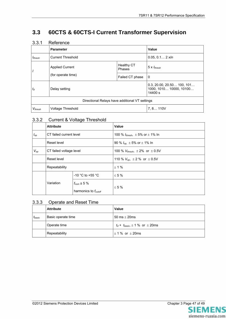
3.3 60CTS & 60CTS-I Current Transformer Supervision
3.3.1 Reference Parameter Value
Ithresh Current Threshold 0.05, 0.1… 2 xIn
Healthy CT Phases 5 x Ithresh
I Applied Current
(for operate time) Failed CT phase 0
td Delay setting 0.3, 20.00, 20.50… 100, 101… 1000, 1010… 10000, 10100… 14400 s
Directional Relays have additional VT settings
Vthresh Voltage Threshold 7, 8… 110V
3.3.2 Current & Voltage Threshold Attribute Value
Iop CT failed current level 100 % Ithresh, ± 5% or ± 1% In
Reset level 90 % Iop, ± 5% or ± 1% In
Vop CT failed voltage level 100 % Vthresh, ± 2% or ± 0.5V
Reset level 110 % Vop, ± 2 % or ± 0.5V
Repeatability ± 1 %
-10 °C to +55 °C ≤ 5 %
Variation fnom ± 5 %
harmonics to fcutoff ≤ 5 %
3.3.3 Operate and Reset Time Attribute Value
tbasic Basic operate time 50 ms ± 20ms
Operate time td + tbasic, ± 1 % or ± 20ms
Repeatability ± 1 % or ± 20ms
©2012 Siemens Protection Devices Limited Chapter 3 Page 47 of 49

7SR11 & 7SR12 Performance Specification
3.4 60VTS Voltage Transformer Supervision
3.4.1 Reference Parameter Value
Vnps Vnps Level 7, 8 … 110V
Inps Inps Level 0.05, 0.1 … 1 x In
Ipps Ipps Load Level 0.05, 0.1 … 1 x In
IFpps Ipps Fault Level 0.05, 0.1 … 20 x In
Vpps Vpps Level 1, 2 … 110V
td 60VTS Delay 0.00, 0.01…20.00, 20.10… 100, 101… 1000, 1010… 10000, 10100… 14400 s
3.4.2 Operate and Reset Level Attribute Value
VNPSop Voltage NPS operate level 100 % Vnps, ± 5 % Vn
Voltage NPS reset level 90 % VNPSop, ± 5 % Vn
VPPSop Voltage PPS operate level 100 % Vpps, ± 5 % Vn
Voltage PPS reset level 110 % VPPSop, ± 5 % Vn
INPSblk Current NPS operate level 100 % Inps, ± 5 % xIn
Current NPS reset level 90 % INPSblk, ± 5 % xIn
IPPSblk Current PPS operate level 100 % IFpps, ± 5 % xIn
Current PPS reset level 90 % IPPSblk, ± 5 % xIn
IPPSload Current PPS operate level 100 % Ipps, ± 5 % xIn
Current PPS reset level 90 % IPPSload, ± 5 % xIn
Repeatability ± 1 %
-10 °C to +55 °C ≤ 5 %
Variation
fnom ± 5 % ≤ 5 %
3.4.3 Operate and Reset Time Attribute Value
tbasic Basic operate time 0V to 2 x Vs 32 ms ± 10ms
Operate time td + tbasic ± 1 % or ± 10ms
Repeatability ± 1 % or ± 10ms
©2012 Siemens Protection Devices Limited Chapter 3 Page 48 of 49

7SR11 & 7SR12 Performance Specification
3.5 74TCS & 74CCS Trip & Close Circuit Supervision
3.5.1 Reference Parameter Value
td Delay setting 0, 0.02…60 s
3.5.2 Operate and Reset Time Attribute Value
tbasic Element basic operate time 30ms ± 10ms
top Operate time following delay tbasic + td, ± 1 % or ± 10ms
Repeatability ± 1 % or ± 10ms
-10 °C to +55 °C ≤ 5 % Variation
fnom ± 5 % ≤ 5 %
3.6 81HBL2 Inrush Detector
3.6.1 Reference Parameter Value
I Setting (Ratio of 2nd Harmonic current to Fundamental component current)
0.10, 0.11... 0.5
3.6.2 Operate and Reset Time Attribute Value
tbasic Element basic operate time Will pick-up before operation of any protection element due to magnetic inrush
Reset Time Will operate until drop-off of any protection element due to magnetic inrush
©2012 Siemens Protection Devices Limited Chapter 3 Page 49 of 49
Related Documents