Copyright © Nex-G | Skills , NESPL Physical Layer Protocol

Welcome message from author
This document is posted to help you gain knowledge. Please leave a comment to let me know what you think about it! Share it to your friends and learn new things together.
Transcript

Copyright © Nex-G | Skills , NESPL
Physical Layer Protocol
Copyright © Nex-G | Skills , NESPL
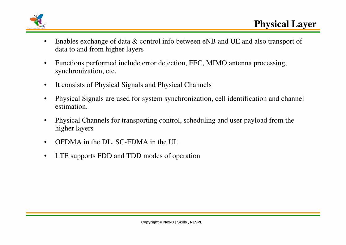
• Enables exchange of data & control info between eNB and UE and also transport of data to and from higher layers
• Functions performed include error detection, FEC, MIMO antenna processing, synchronization, etc.
• It consists of Physical Signals and Physical Channels
• Physical Signals are used for system synchronization, cell identification and channel estimation.
• Physical Channels for transporting control, scheduling and user payload from the higher layers
• OFDMA in the DL, SC-FDMA in the UL
• LTE supports FDD and TDD modes of operation
Physical Layer
Copyright © Nex-G | Skills , NESPL
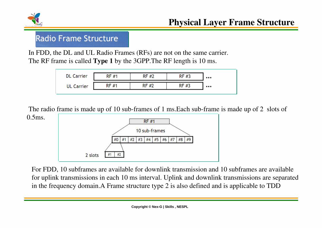
In FDD, the DL and UL Radio Frames (RFs) are not on the same carrier. The RF frame is called Type 1 by the 3GPP.The RF length is 10 ms.
The radio frame is made up of 10 sub-frames of 1 ms.Each sub-frame is made up of 2 slots of 0.5ms.
For FDD, 10 subframes are available for downlink transmission and 10 subframes are available for uplink transmissions in each 10 ms interval. Uplink and downlink transmissions are separated in the frequency domain.A Frame structure type 2 is also defined and is applicable to TDD
Physical Layer Frame Structure

Copyright © Nex-G | Skills , NESPL
Each slot is made up of: 7 symbols in case of normal CP (guard time between symbols)
Tu = Useful Symbol DurationTcp = Cyclic Prefix durationTecp = Extended Cyclic Prefix duration
Since OFDM offers a better flexibility in terms of sub-frame structure and pilot allocation, there is no reason to consider the same structure as for DFT-SOFDM.
Physical Layer Frame Structure

Copyright © Nex-G | Skills , NESPL
The frame structure for the Type 2 frames used on LTE TDD is somewhat different. The 10 ms frame comprises two half frames, each 5 ms long. The LTE half-frames are further split into five sub frames, each 1ms long.
The subframes may be divided into standard subframes of special subframes. The special subframes consist of three fields:• DwPTS - Downlink Pilot Time Slot •GP - Guard Period •UpPTS - Uplink Pilot Time Stot.
These three fields are also used within TD-SCDMA and they have been carried over into LTE TDD (TD-LTE) and thereby help the upgrade path. The fields are individually configurable in terms of length, although the total length of all three together must be 1ms.
Physical Layer Frame Structure

Copyright © Nex-G | Skills , NESPL
• LTE Frame Structure Type I (FDD)
• LTE Frame Structure Type II (TDD)
Physical Layer Frame Structure

Copyright © Nex-G | Skills , NESPL
Resource Block
Multiplex multiple users both in time and frequency, together with pilots and control signals.The time-frequency plane is divided into chunks=minimum resource allocation unit.The traffic multiplexing is performed by allocating to each user a certain number of chunks depending on its data rate/geometry.

Copyright © Nex-G | Skills , NESPL
Physical Resource Block
In OFDMA, users are allocated a specific number of subcarriers for a predetermined amount of time. These are referred to as physical resource blocks (PRBs) in the LTE specifications.
PRBs have both a time and frequency dimension. Allocation of PRBs is handled by a scheduling function at the 3GPP base station (eNodeB).

Copyright © Nex-G | Skills , NESPL
Resource Element Group
For the control channel, the radio signaling, the Resource Block is not the adapted unit.The control channels mapped on the Resource Elements Groups (REGs), which represent less radio resources.A REG is made up of 4 (or 6 if there are pilot sub-carriers) sub-carriers during 1 symbol. The REG are grouped into the CCE (Control Channel Element)
Resource element groups are used for defining the mapping of control channels to resource elements.

Copyright © Nex-G | Skills , NESPL

Copyright © Nex-G | Skills , NESPL
FDD (left) and TDD (right) frequency bands defined in the 3GPP

Copyright © Nex-G | Skills , NESPL
Downlink Transmission Scheme-OFDMA
• The downlink transmission scheme for E-UTRA FDD and TDD modes is based on conventional OFDM. In an OFDM system, the available spectrum is divided into multiple carriers, called sub-carriers, which are orthogonal to each other. Each of these sub-carriers is independently modulated by a low rate data stream.
• OFDM is used as well in WLAN, WiMAX and broadcast technologies like DVB. OFDM has several benefits including its robustness against multipath fading and its efficient receiver architecture.

Copyright © Nex-G | Skills , NESPL
OFDM
• Single Carrier Transmission (e.g. WCDMA)
• Orthogonal Frequency Division Multiplexing
Copyright © Nex-G | Skills , NESPL
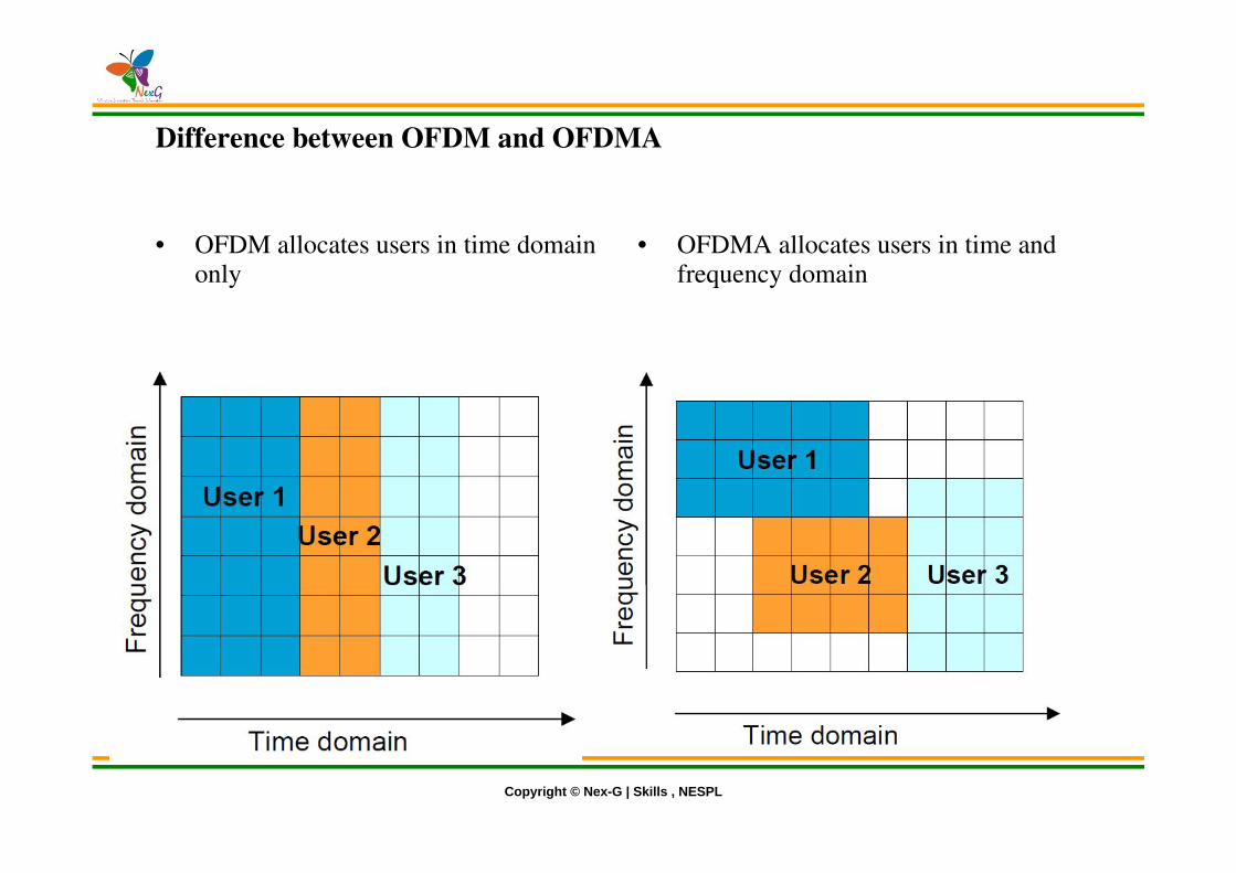
Difference between OFDM and OFDMA
• OFDM allocates users in time domain only
• OFDMA allocates users in time and frequency domain
Copyright © Nex-G | Skills , NESPL
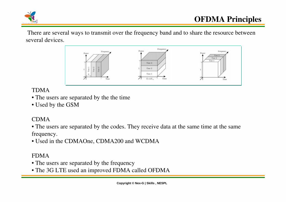
There are several ways to transmit over the frequency band and to share the resource between several devices.
TDMA• The users are separated by the the time• Used by the GSM
CDMA• The users are separated by the codes. They receive data at the same time at the same frequency.• Used in the CDMAOne, CDMA200 and WCDMA
FDMA• The users are separated by the frequency• The 3G LTE used an improved FDMA called OFDMA
OFDMA Principles

Copyright © Nex-G | Skills , NESPL
Notion of Orthogonality
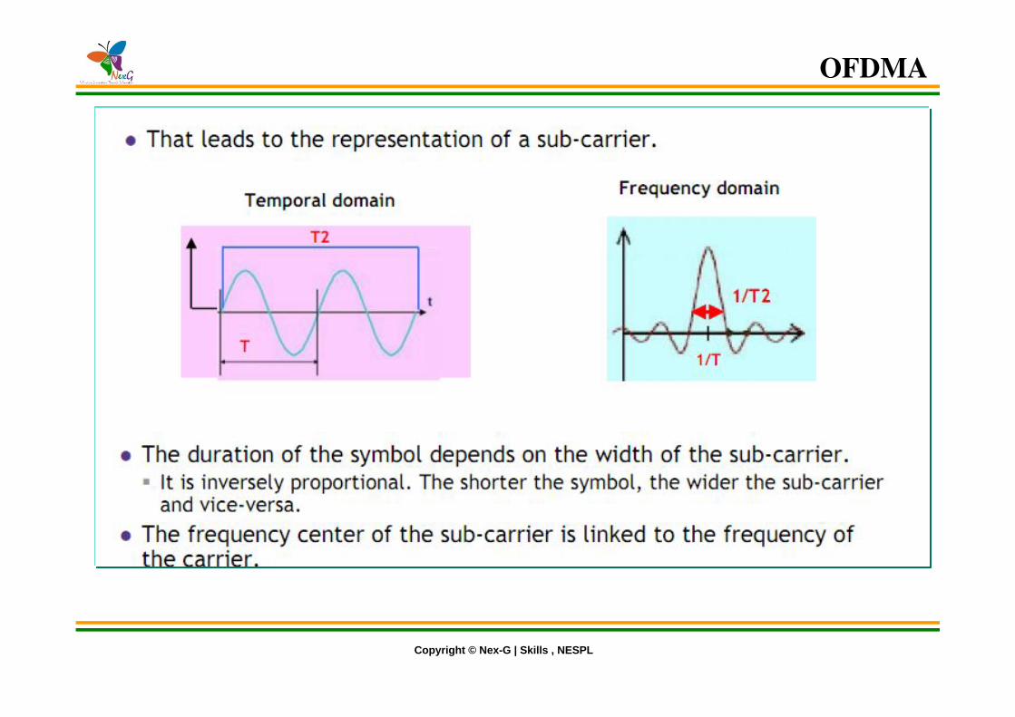
In OFDM, the sub-carrier frequencies are chosen so that the sub-carriers are orthogonal to each other, meaning that cross-talk between the sub-channels is eliminated and inter-carrier guard bands are not required. This greatly simplifies the design of both the transmitterand the receiver; unlike conventional FDM a separate filter for each sub-channel is not required.The orthogonality requires that the sub-carrier spacing is ∆f = k/(TU) Hertz, where TU seconds is the useful symbol duration (the receiver side window size), and k is a positive integer, typically equal to 1. Therefore, with N sub-carriers, the total passband bandwidth will be B ˜ N—∆f (Hz).
OFDMA
Copyright © Nex-G | Skills , NESPL
OFDMA

Copyright © Nex-G | Skills , NESPL
The inter-channel (or inter sub-carrier) interferences are cancelled because they are located in a such way that when there is the peak for a given sub-carrier, the adjacent subcarriers are null.
OFDM allows high density of carriers, without generating Inter-Channel Interference (ICI).
OFDMA

Copyright © Nex-G | Skills , NESPL
BASIC IDEA: The channel bandwidth is divided into multiple subchannels to reduce ISI and frequency-selective fading. A single wideband signal is transformed into multiple narrow band signals transmitted on orthogonal subcarriers• One single stream at high rate•Each symbol occupies the whole bandwidth•Very short symbol duration to ensure high rate
OFDMA
Copyright © Nex-G | Skills , NESPL
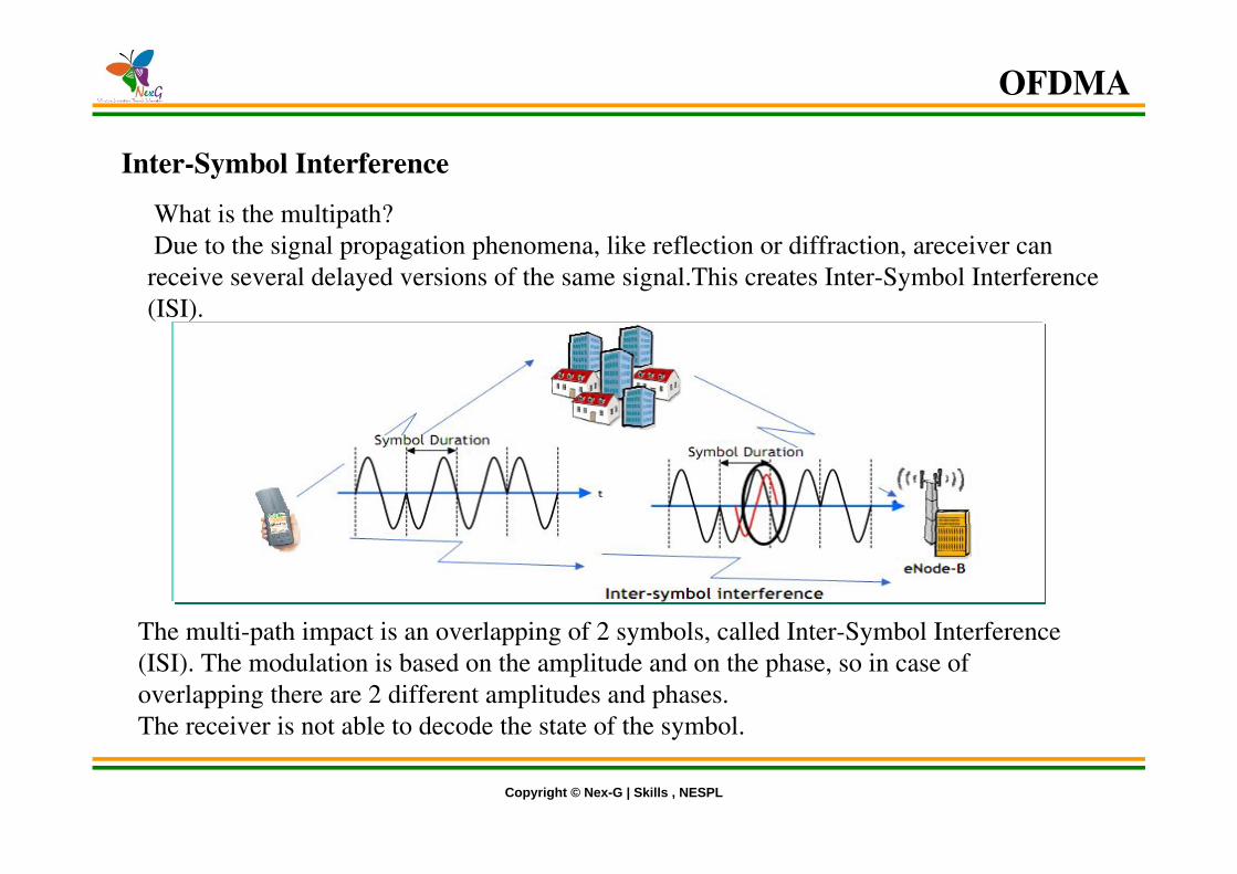
Inter-Symbol Interference
What is the multipath? Due to the signal propagation phenomena, like reflection or diffraction, areceiver can receive several delayed versions of the same signal.This creates Inter-Symbol Interference (ISI).
The multi-path impact is an overlapping of 2 symbols, called Inter-Symbol Interference (ISI). The modulation is based on the amplitude and on the phase, so in case of overlapping there are 2 different amplitudes and phases.The receiver is not able to decode the state of the symbol.
OFDMA

Copyright © Nex-G | Skills , NESPL
The problem is fixed by adding a guard time between each symbol to avoid the ISI. The ISI is still present but is not disturbing for the receiver.
Cyclic Prefix
Principle : add a prefix to absorb channel effect and avoid ISI Cyclic prefix permits to facilitate demodulation The cyclic prefix transform the classical channel convolution into a cyclic convolution which permits easy demodulation after FFT
OFDMA

Copyright © Nex-G | Skills , NESPL
The guard time is called the Cyclic Prefix (CP). It permits to facilitate demodulation.
The cyclic prefix transforms the classical channel convolution into acyclic convolution which permits easy demodulation after FFT.
Cyclic Prefix
OFDMA

Copyright © Nex-G | Skills , NESPL
OFDMA Transmitter
OFDMA

Copyright © Nex-G | Skills , NESPL
In the downlink, OFDM is selected to efficiently meet E-UTRA performance requirements. With OFDM, it is straightforward to exploit frequency selectivity of the multi-path channel with low complexity receivers. This allows frequency selective in addition to frequency diverse scheduling and one cell reuse of available bandwidth.
Furthermore, due to its frequency domain nature, OFDM enables flexible bandwidth operation with low complexity. Smart antenna technologies are also easier to support with OFDM, sinceeach sub-carrier becomes flat faded and the antenna weights can be optimized on a per sub-carrier (or block of sub-carriers) basis.
In addition, OFDM enables broadcast services on a synchronized single frequency network (SFN) with appropriate cyclic prefix design.This allows broadcast signals from different cells to combine over the air, thus significantly increasing the received signal power and supportable data rates for broadcast services.
OFDMA

Copyright © Nex-G | Skills , NESPL
OFDMA Receiver
OFDMA

Copyright © Nex-G | Skills , NESPL
OFDMA Advantages
• Robust against narrow-band co-channel interference Robust against Intersymbol interference (ISI) and fading• High spectral efficiency Efficient implementation using FFT
Drawbacks
• High Peak-to-Average Power Ratio
•The power limitation is more problematic in UL than in DL•Signal with high PAPR will limit the Tx power in UL and reduce coverage
OFDMA

Copyright © Nex-G | Skills , NESPL
Downlink Physical Layer Procedures
Cell search and synchronization:
• Scheduling: Scheduling is done in the base station (eNodeB). The downlink control channel PDCCH informs the users about their allocated time/frequency resources and the transmission formats to use. The scheduler evaluates different types of information, e.g. Quality of Service parameters, measurements from the UE, UE capabilities, buffer status.
• Link Adaptation: Link adaptation is already known from HSDPA as Adaptive Modulation and Coding. Also in E-UTRA, modulation and coding for the shared data channel is not fix, but it is adapted according to radio link quality. For this purpose, the UE regularly reports Channel Quality Indications (CQI) to the eNodeB.
• Hybrid ARQ (Automatic Repeat Request): Downlink Hybrid ARQ is also known from HSDPA. It is a retransmission protocol. The UE can request retransmissions of incorrectly received data packets.

Copyright © Nex-G | Skills , NESPL
LTE uses in UL a modified form of OFDMA process, called SC-FDMA SC-FDMA = Single Carrier – Frequency Division Multiple Access SC-FDMA improves the peak-to-average power ratio (PAPR) compared to OFDM
Reduced power amplifier cost for mobile Reduced power amplifier back-off improved coverage
In DL, use OFDM together with some PAPR reduction techniques (“clipping and filtering”, “tones reservation”, etc…)In UL, find an alternative to OFDM combining some of OFDM’s advantages, but with a PAPR equivalent to single carrier’s one: DFT-Spread OFDM(DFT-SOFDM), also known as Single-Carrier FDMA (SC-FDMA)
Uplink Transmission Scheme-SCFDMA
Copyright © Nex-G | Skills , NESPL
• Thus, the LTE uplink transmission scheme for FDD and TDD mode is based on SC-FDMA (Single Carrier Frequency Division Multiple Access) with cyclic prefix.
• SC-FDMA signals have better PAPR properties compared to an OFDMA signal.
• This was one of the main reasons for selecting SCFDMA as LTE uplink access scheme.
• The PAPR characteristics are important for cost-effective design of UE power amplifiers.
• Still, SC-FDMA signal processing has some similarities with OFDMA signal processing, so parameterization of downlink and uplink can be harmonized.
SCFDMA
Copyright © Nex-G | Skills , NESPL
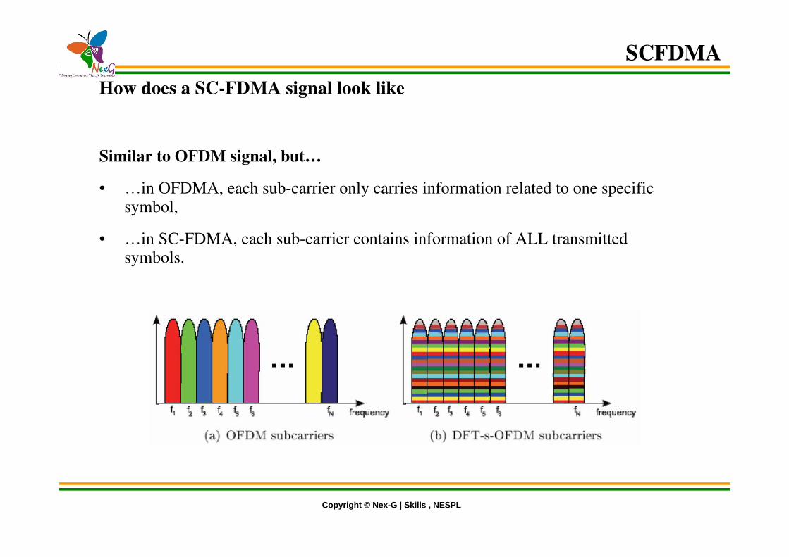
How does a SC-FDMA signal look like
Similar to OFDM signal, but…
• …in OFDMA, each sub-carrier only carries information related to one specific symbol,
• …in SC-FDMA, each sub-carrier contains information of ALL transmitted symbols.
SCFDMA

Copyright © Nex-G | Skills , NESPL
DFT-spread OFDM (DFTS-OFDM) is a transmission scheme that can combinethe desired properties discussed in the previous sections, i.e.:• Small variations in the instantaneous power of the transmitted signal (‘singlecarrier’ property).• Possibility for low-complexity high-quality equalization in the frequency domain.• Possibility for FDMA with flexible bandwidth assignment.Due to these properties, DFTS-OFDM has been selected as the uplink transmission scheme for LTE
Benefits
SCFDMA

Copyright © Nex-G | Skills , NESPL
UL Physical Channel Processing
SCFDMA
Copyright © Nex-G | Skills , NESPL
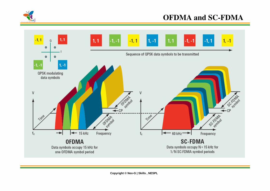
OFDMA and SC-FDMA
Copyright © Nex-G | Skills , NESPL
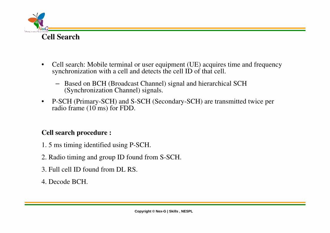
Cell Search
• Cell search: Mobile terminal or user equipment (UE) acquires time and frequency synchronization with a cell and detects the cell ID of that cell.– Based on BCH (Broadcast Channel) signal and hierarchical SCH
(Synchronization Channel) signals.• P-SCH (Primary-SCH) and S-SCH (Secondary-SCH) are transmitted twice per
radio frame (10 ms) for FDD.
Cell search procedure :
1. 5 ms timing identified using P-SCH.2. Radio timing and group ID found from S-SCH.3. Full cell ID found from DL RS.4. Decode BCH.

Copyright © Nex-G | Skills , NESPL
LTE MIMO concept

Copyright © Nex-G | Skills , NESPL
Multiple Antenna Schemes in LTE
• In DL : Tx diversity, Rx diversity, Spatial multiplexing (2x2,4x2 configurations – SU-MIMO and MU-MIMO) supported
• In UL : Only 1 Transmitter (antenna selection Tx diversity ), MU-MIMO possible, Rx diversity with 2 or 4 antennas at eNB supported
LTE MIMO concept
Copyright © Nex-G | Skills , NESPL
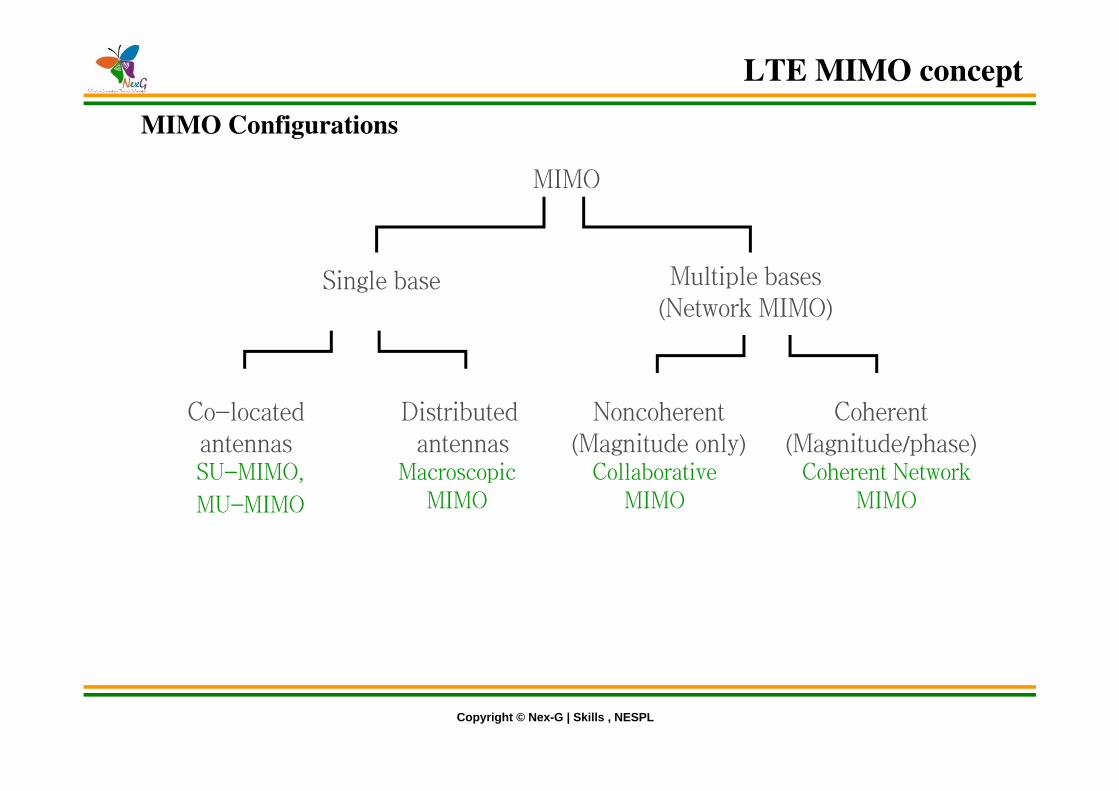
MIMO Configurations
MIMO
Single base Multiple bases(Network MIMO)
Co-locatedantennas
Distributed antennas
Noncoherent(Magnitude only)
Coherent(Magnitude/phase)
MacroscopicMIMO
CollaborativeMIMO
Coherent NetworkMIMO
SU-MIMO,MU-MIMO
LTE MIMO concept

Copyright © Nex-G | Skills , NESPL
Spatial Multiplexing
Spatial multiplexing allows to transmit different streams of data simultaneously on the same downlink resource block(s). These data streams can belong to one single user (single user MIMO / SU-MIMO) or to different users (multi user MIMO / MU-MIMO). While SU-MIMO increases the data rate of one user, MU-MIMO allows to increase the overall capacity.Spatial multiplexing is only possible if the mobile radio channel allows it.
LTE MIMO concept
Related Documents