OWNERS MANUAL INSTALLATION AND OPERATING INSTRUCTIONS MODEL 7900 OPHTHALMIC INSTRUMENT STAND EN FR

Welcome message from author
This document is posted to help you gain knowledge. Please leave a comment to let me know what you think about it! Share it to your friends and learn new things together.
Transcript

OWNERS MANUAL
INSTALLATION AND OPERATING INSTRUCTIONS
MODEL 7900 OPHTHALMIC INSTRUMENT STAND
EN FR

QUALITY MANAGEMENT SYSTEM
REGISTERED TOISO 13485
MADE IN AMERICA
Reliance® Medical Products, Inc. • 3535 Kings Mills Road • Mason, Ohio 45040-2303 • 1-800-735-0357 • www.reliance-medical.com
SERIAL NUMBERFor your future reference, mark the serial number in the space provided.
2

3
Table of Contents
IMPORTANT INFORMATION.......................................4
1. INTRODUCTION...................................................5
TECHNICAL SPECIFICATIONS................................6
2. INSTALLATION..................................................7
2.1 UNPACKING.........................................................7
2.1.1 Base Unit.........................................................7
2.2 Instrument Console/Base Cap.......................7
2.3 Support Column Installation..........................9
2.4 Configuring The System...................................9
2.4.1 Console: Configuring Dip Switches (SW2)..........9
2.4.2 Base Cap: Configuring The Beep-On-Switch Feature..................................................................9
2.5 Third Arm.......................................................10
2.6 Refractor Arm - Dual Lock.............................11
2.7 Overhead Lamp..............................................11
2.8 Final Assembly...........................................11
2.8.1 Console/Base Cap......................................11
2.9 Slit Lamp Arm......................................11
2.10 Chair Assembly............................................12
2.11 Miscellaneous.............................................13
3. OPERATING INSTRUCTIONS............................13
3.1 Slit Lamp Arm......................................13
3.2 Third Arm.......................................................14
3.3 Refractor Arm....................................15
3.4 Overhead Lamp............................................15
3.5 Instrument Console/Base Cap....................15
Hand Instrument Wells - Rechargeable Battery Type (Console only).........................15
3.6 Front Panel Controls.............................16
Standby Switch (STBY) ...............................16
Auxiliary Switch (AUX1)................................16
Room Switch (ROOM)...........................17
Room Down Switch..................................17
Room Up Switch............................................17
Lamp Switch (LAMP).........................................17
Lamp Down Switch..................................17
Lamp Up Switch............................................17
Binding Post Switch (B/P)............................17
B/P Down Switch...........................................17
B/P Up Switch................................................17
Chair Base Up Switch...................................17
Chair Base Down Switch..............................17
Auto Switch............................................17
3.7 Fuses...........................................................18
3.8. ECLIPSE® Infrared Room (IR) Three Zone Light Control System ...................................................18
Three Zones System..........................................19
Scenes..........................................................19
Switchpack #1 (SW1).................................19
Entering and Exiting Programming Mode......21
TROUBLESHOOTING GUIDE........................27
TROUBLESHOOTING GUIDE ECLIPSE® L ight Control System...........................................28
CLEANING AND MAINTENANCE .....................29
PARTS LIST.....................................................30
Model 7900 Instrument Stand Assembly...................31
Base Assembly.............................................32
Roller Frame Assembly................................34
Outlet Plate Assembly.................................36
Back Cover Assembly.....................................38
Slit Lamp Arm Assembly..............................40
Model 5250 Dual Lock Refractor ASSEMBLY......42
Model 5380 Auxiliary (3rd) Arm Assembly...44
Instrument Console Without IR Assembly........46
Instrument Console With IR Assembly..........48
Base Cap With IR Assembly...............................50 Wire Diagram - Console (With and Without IR) ...52
Wire Diagram Base Cap With IR.............................54
LIMITED WARRANTY..........................................59
IN-7900
IMPORTANT INFORMATION
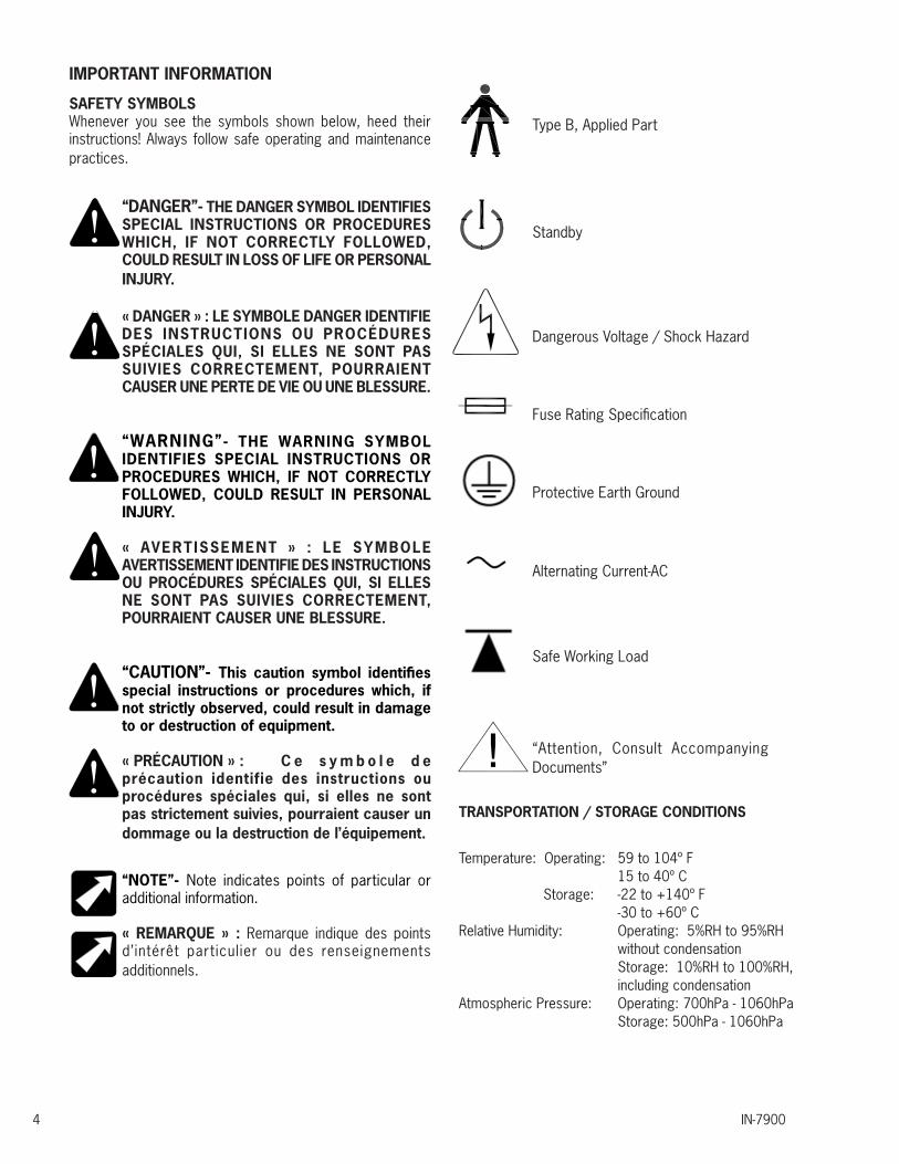
SAFETY SYMBOLSWhenever you see the symbols shown below, heed their instructions! Always follow safe operating and maintenance practices.
“DANGER”- THE DANGER SYMBOL IDENTIFIES SPECIAL INSTRUCTIONS OR PROCEDURES WHICH, IF NOT CORRECTLY FOLLOWED, COULD RESULT IN LOSS OF LIFE OR PERSONAL INJURY.
« DANGER » : LE SYMBOLE DANGER IDENTIFIE DES INSTRUCTIONS OU PROCÉDURES SPÉCIALES QUI, SI ELLES NE SONT PAS SUIVIES CORRECTEMENT, POURRAIENT CAUSER UNE PERTE DE VIE OU UNE BLESSURE.
“WARNING”- THE WARNING SYMBOL IDENTIFIES SPECIAL INSTRUCTIONS OR PROCEDURES WHICH, IF NOT CORRECTLY FOLLOWED, COULD RESULT IN PERSONAL INJURY.
« AVERTISSEMENT » : LE SYMBOLE AVERTISSEMENT IDENTIFIE DES INSTRUCTIONS OU PROCÉDURES SPÉCIALES QUI, SI ELLES NE SONT PAS SUIVIES CORRECTEMENT, POURRAIENT CAUSER UNE BLESSURE.
“CAUTION”- This caution symbol identifies special instructions or procedures which, if not strictly observed, could result in damage to or destruction of equipment.
« PRÉCAUTION » : C e s y m b o l e d e précaution identifie des instructions ou procédures spéciales qui, si elles ne sont pas strictement suivies, pourraient causer un dommage ou la destruction de l’équipement.
“NOTE”- Note indicates points of particular or additional information.
« REMARQUE » : Remarque indique des points d’intérêt particulier ou des renseignements additionnels.
IN-79004
TRANSPORTATION / STORAGE CONDITIONS
Temperature: Operating: 59 to 104º F 15 to 40º C Storage: -22 to +140º F -30 to +60º CRelative Humidity: Operating: 5%RH to 95%RH without condensation Storage: 10%RH to 100%RH, including condensationAtmospheric Pressure: Operating: 700hPa - 1060hPa Storage: 500hPa - 1060hPa
Type B, Applied Part
Standby
Dangerous Voltage / Shock Hazard
Fuse Rating Specification
Protective Earth Ground
Alternating Current-AC
Safe Working Load
“Attention, Consult Accompanying Documents” !

AVERT ISSEMENT : POUR ÉV ITER UNE BLESSURE OU UN DOMMAGE À L’ÉQUIPEMENT, SEULS LES DISTRIBUTEURS RELIANCE® AUTORISÉS DEVRAIENT INSTALLER OU DÉPLACER L’ÉQUIPEMENT.
WARNING: TO PREVENT FIRE OR ELECTRICAL SHOCK HAZARD, DO NOT EXPOSE THIS EQUIPMENT TO RAIN OR MOISTURE.
AVERTISSEMENT : POUR ÉVITER UN INCENDIE OU UN RISQUE DE CHOC ÉLECTRIQUE, N’EXPOSEZ PAS CET ÉQUIPEMENT À LA PLUIE OU À L’HUMIDITÉ.
WARNING- TO AVOID PERSONAL INJURY OR DAMAGE TO THE EQUIPMENT, ONLY TRAINED/QUALIFIED PERSONNEL WHO HAVE READ THIS MANUAL SHOULD OPERATE THIS EQUIPMENT. OPERATION BY UNAU-THORIZED USERS SHOULD BE PREVENTED.
AVERTISSEMENT : POUR ÉVITER UNE BLESSURE OU UN DOMMAGE À L’ÉQUIPEMENT, SEUL DU PERSONNEL ENTRAÎNÉ/QUALIFIÉ QUI A LU CE MANUEL DEVRAIT FAIRE FONCTIONNER CET ÉQUIPEMENT. LE FONCTIONNEMENT PAR DES UTILISATEURS NON AUTORISÉS DEVRAIT ÊTRE ÉVITÉ.
WARNING- TO AVOID PERSONAL INJURY OR DAMAGE TO THE EQUIPMENT, CALL YOUR AUTHORIZED RELIANCE® DISTRIBUTOR OR THE TECHNICAL SERVICE DEPARTMENT IF ANY PART OF THE EQUIPMENT FAILS. ONGO-ING USE OF MALFUNCTIONING EQUIPMENT IS NOT RECOMMENDED.
AVERTISSEMENT : POUR ÉVITER UNE BLESSURE OU UN DOMMAGE À L’ÉQU IPEMENT, APPELEZ VOTRE DISTRIBUTEUR RELIANCE® AUTORISÉ OU LES SERVICES TECHNIQUES SI UNE PARTIE QUELCONQUE DE L’ÉQUIPEMENT TOMBE EN PANNE. L’UTILISATION CONTINUE D’UN ÉQUIPEMENT DÉFAILLANT N’EST PAS RECOMMANDÉE.
IN-7900 5
1. INTRODUCTION
1.1. This Installation and Operating Instruction contains information applicable only to the Reliance® Model 7900 Ophthalmic Instrument Stand also known as Floor Unit.
1.2. Should your product not perform properly, or if you have any questions concerning the use and care of any Reliance® product, contact the Authorized Reliance® Distributor where you purchased this product or contact the Technical Service Department, Reliance® Medical Products, Inc., 3535 Kings Mills Road, Mason, Ohio 45040-2303, or call (800) 735-0358.
NOTE: Always have the model number and serial number available before contacting Reliance® or your Authorized Reliance® Distributor.
REMARQUE : Ayez toujours le numéro de modèle et le numéro de série à portée de la main avant de contacter Reliance® ou votre distributeur Reliance® autorisé.
“CLASSIFIED BY CANADIAN STANDARDS ASSOCIATION® CSA WITH RESPECT TO ELECTRIC SHOCK, FIRE AND MECHANICAL HAZARDS ONLY IN ACCORDANCE WITH IEC 60601-1.”
According to Clause 5 in IEC 60601-1, sec 6.8.1, this Unit is classified by the following:
• The type of protection against electric shock: EQUIPMENT energized from an external electrical power source: CLASS I EQUIPMENT
• The degree of protection against electric shock: TYPE B EQUIPMENT
• The degree of protection against harmful ingress of water: ORDINARY DEGREE
• The degree of safety of application in the presence of a FLAMMABLE ANESTHETIC MIXTURE WITH AIR or WITH OXYGEN OR NITROUS OXIDE: EQUIPMENT not suitable for use in the presence of a FLAMMABLE ANESTHETIC MIXTURE WITH AIR or WITH OXYGEN OR NITROUS OXIDE
• The mode of operation: CONTINUOUS OPERATION
WARNING: TO AVOID PERSONAL INJURY OR DAMAGE TO THE EQUIPMENT, ONLY AUTHORIZED RELIANCE® DISTRIBUTORS SHOULD INSTALL OR MOVE THE EQUIPMENT.
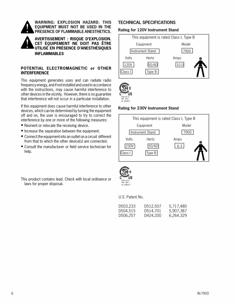
WARNING: EXPLOSION HAZARD. THIS EQUIPMENT MUST NOT BE USED IN THE PRESENCE OF FLAMMABLE ANESTHETICS.
AVERTISSEMENT : RISQUE D’EXPLOSION. CET ÉQUIPEMENT NE DOIT PAS ÊTRE UTILISÉ EN PRÉSENCE D’ANESTHÉSIQUES INFLAMMABLES
POTENTIAL ELECTROMAGNETIC or OTHER INTERFERENCE
This equipment generates uses and can radiate radio frequency energy, and if not installed and used in accordance with the instructions, may cause harmful interference to other devices in the vicinity. However, there is no guarantee that interference will not occur in a particular installation.
If this equipment does cause harmful interference to other devices, which can be determined by turning the equipment off and on, the user is encouraged to try to correct the interference by one or more of the following measures:• Reorient or relocate the receiving device.• Increase the separation between the equipment.• Connect the equipment into an outlet on a circuit different
from that to which the other device(s) are connected.• Consult the manufacturer or field service technician for
help.
This product contains lead. Check with local ordinance or laws for proper disposal.
IN-79006
TECHNICAL SPECIFICATIONS
Rating for 120V Instrument Stand
This equipment is rated Class I, Type B
Equipment Model
Instrument Stand 7900
Volts Hertz Amps
120V 50/60 10.0
Class I Type B
Rating for 230V Instrument Stand
This equipment is rated Class I, Type B
Equipment Model
Instrument Stand 7900
Volts Hertz Amps
230V 50/60 6.3
Class I Type B
U.S. Patent No.
D503,233 D512,507 5,717,480D504,515 D514,701 5,907,387D506,257 D424,200 6,264,329
AV E R T I S S E M E N T : R I S Q U E D E BASCULEMENT. NE REGROUPEZ JAMAIS LES TROIS BRAS D’ INSTRUMENTS ENSEMBLE SUR UN CÔTÉ DU SUPPORT. DISTRIBUEZ LE POIDS DES INSTRUMENTS AUSSI ÉGALEMENT QUE POSSIBLE. ÉVITEZ UN MOUVEMENT RAPIDE OU VIOLENT DES BRAS D’INSTRUMENTS.
2.2. Instrument Console/Base Cap
CAUTION- The power supply cord should not be connected to the power supply during the installation process.
PRÉCAUTION : Le cordon d’alimentation ne devrait pas être connecté au bloc d’al imentat ion durant le processus d’installation.
2. INSTALLATION
2.1. Unpacking
2.1.1. Base Unit
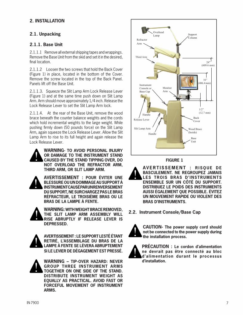
2.1.1.1 Remove all external shipping tapes and wrappings. Remove the Base Unit from the skid and set it in the desired, final location.
2.1.1.2 Loosen the two screws that hold the Back Cover (Figure 1) in place, located in the bottom of the Cover. Remove the screw located in the top of the Back Panel. Panels lift off the Base Unit.
2.1.1.3. Squeeze the Slit Lamp Arm Lock Release Lever (Figure 1) and at the same time push down on Slit Lamp Arm. Arm should move approximately 1/4 inch. Release the Lock Release Lever to set the Slit Lamp Arm lock.
2.1.1.4. At the rear of the Base Unit, remove the wood brace beneath the counter balance weights and the cords which hold incremental weights to the large weight. While pushing firmly down (50 pounds force) on the Slit Lamp Arm, again squeeze the Lock Release Lever. Allow the Slit Lamp Arm to rise to its full height and again release the Lock Release Lever.
WARNING- TO AVOID PERSONAL INJURY OR DAMAGE TO THE INSTRUMENT STAND CAUSED BY THE STAND TIPPING OVER, DO NOT OVERLOAD THE REFRACTOR ARM, THIRD ARM, OR SLIT LAMP ARM.
AVERTISSEMENT : POUR ÉVITER UNE BLESSURE OU UN DOMMAGE AU SUPPORT À INSTRUMENT CAUSÉ PAR UN RENVERSEMENT DU SUPPORT, NE SURCHARGEZ PAS LE BRAS RÉFRACTEUR, LE TROISIÈME BRAS OU LE BRAS DE LA LAMPE À FENTE.
WARNING: WITH WEIGHT BRACE REMOVED, THE SLIT LAMP ARM ASSEMBLY WILL RISE ABRUPTLY IF RELEASE LEVER IS DEPRESSED.
AVERTISSEMENT : LE SUPPORT LESTÉ ÉTANT RETIRÉ, L’ASSEMBLAGE DU BRAS DE LA LAMPE À FENTE SE LÈVERA ABRUPTEMENT SI LE LEVIER DE DÉGAGEMENT EST PRESSÉ.
WARNING – TIP-OVER HAZARD: NEVER GROUP THREE INSTRUMENT ARMS TOGETHER ON ONE SIDE OF THE STAND. DISTRIBUTE INSTRUMENT WEIGHT AS EQUALLY AS PRACTICAL. AVOID FAST OR FORCEFUL MOVEMENT OF INSTRUMENT ARMS.
IN-7900 7
FIGURE 1
InstrumentConsole or Base Cap
SupportColumn
Release Lever
Handle
Slit Lamp Arm
Handle
BackCover
BaseUnit
Wood Brace(Inside)
Third Arm
RefractorArm
OverheadLamp
MonitorArm
24” (609.6 mm)
16”(406.4 mm)
1/2”(12.7 mm)

IN-79008
NOTE: If you are installing room light controls on this Instrument Stand, also refer to the “ECLIPSE® Room Light Control Operating Instructions Section.”
REMARQUE : S i vous insta l lez des commandes d’éclairage salle sur ce stand instrument, se reporter également à la “ECLIPSE ® light salle de contrôle d’exploitation des instructions de l’article.”
2.2.1. Replacement or Repair
In the event that the Instrument Console or Base Cap must be mounted or removed for replacement or repair purposes, it will be necessary to temporarily remove any assemblies on the Support Column. To install a Console, connect the four connectors on top of the Base Unit to the matching connectors hanging from the bottom of the Console.
FIGURE 2
The Lamp Jumper Cable will drop through the large opening and be connected to the matching connector that hangs from underneath the Support Column. Figure 2 illustrates the connections that must be made. Align the two pins located near the front of the Console in the matching holes on top of the Base Unit. Gently push the Console down to secure. To disassemble or remove the Console, pull the Console up in the front and disconnect the four connectors from the Base Unit. As mentioned above, any assemblies on Support Column must be removed before the Console itself can be removed. If the Overhead Lamp has not already been removed, the Lamp Jumper must be disconnected from the lamp plug under the Support Column.
Chair Control (Ref)
Overhead Lamp
Slit Lamp Arm from Roller Frame
AC Input from Outlet Plate
3rd Arm from Back Cover
Aux from Back Cover
Overhead Lamp Jumper
B/P Jumper from Module
Chair Control from Outlet Plate
Ground from AC Input
Ground from 3rd Arm & Slit Lamp
OverheadLamp
Switchpack (SW1)Optional
ChairControl
Switchpack (SW2)
Mounting Tabs
FIGURE 2

IN-7900 9
2.3. Support Column Installation
Remove Phillips Head Shipping Screw. Unwrap the Support Column. Remove the column Support Pin and the Collar from the Installation Packet. Insert the Column in the hole at the top of the Base Unit.
CAUTION – Ensure there is a clear path for the support column between the opening in the console and the hole in the base frame. If cables impede path simply move them aside.
PRÉCAUTION : Assurez-vous qu’il y a un passage dégagé pour la colonne de soutien entre l’ouverture dans la console et le trou dans le cadre de la base. si des câbles nuisent, poussez-les simplement de côté.
Line up the hole in the Column with the hole in the Base Unit and insert the Support Pin. Note that the small screw at the top of the Column faces the rear of the Base Unit. Tighten the set screws under the Support Pin. Remove set screw from Installation Packet and install where shipping screw had been. Slide the Collar down firmly against the Console/Base Cap. Insert and tighten set screw.
2.4. CONFIGURING THE SYSTEM
CAUTION – If the Dip Switches are not configured properly before turning on power to the equipment via the STBY Switch, damage to the equipment or Instrument Bulbs may occur.
PRÉCAUTION : Si les commutateurs dip ne sont pas configurés correctement avant d’activer l’alimentation à l’équipement par l’interrupteur STBY (EN ATTENTE), un dommage à l’équipement ou aux bulbes d’instrument peut se produire.
2.4.1. CONSOLE: CONFIGURING DIP SWITCHES ON THE CIRCUIT BOARD (SW2)
2.4.1.1. Switchpack SW2 on the Console must be configured for proper operation of the Stand. Individual switches 1, 2 and 3 control the voltage and power to the Indirect Ophthalmoscope. See Table 1.
BINDINGPOSTS
"3rd" ARM
PROJECTOR
!
FIGURE 3
IN-790010
• Turn Off the Overhead Lamp..• Press and hold the Lamp Down Switch for five (5)
seconds.• If a long 1-second beep is heard, the Beep-on-Switch
Feature has been turned On.• If a short 0.2-second beep is heard, the Beep-on-Switch
Feature has been turned Off.• Simply press and hold the Lamp Up Switch for five (5)
seconds to toggle the Beep-on-Switch Feature On and Off
2.5. Third Arm
2.5.1. If supplied, unpack the Third Arm. Slide the Clamp Sleeve carefully down over the Support Column until positioned as shown in Figure 1. Tighten the clamp screw using the hex key wrench provided.
2.5.2. Position the Clamp initially so that the clamp screw is toward the rear of the Base Unit. If necessary, this position can be altered to center the rotation of the arm about the Column (300°) within the desired range of movement.
2.5.3. Springs are used to counterbalance the Instrument mounted on the arm. Adjustment of the springs is by means of a screw which is accessible upon removal of Plug Button. Rotating the screw clockwise increases the tension. With the Instrument in place, adjust the screw to balance the Instrument.
2.5.4. Plug the Third Arm into the receptacle marked “3RD ARM” located on the Console or Base Cap.
WARNING – THE MAINS OUTLET LOCATED ON THE BACK OF THE CONSOLE OR BASE CAP MARKED “ARM” AND THE MAINS OUTLET LOCATED ON THE THIRD ARM ITSELF, ARE INTENDED TO SUPPLY POWER TO A KERATOMETER OR SIMILAR MEDICAL DEVICE COMPLYING WITH IEC 60601-1. ONCE CONNECTED, RESULTING LEAKAGE CURRENTS MUST COMPLY WITH IEC 60601-1-1 FOR MEDICAL ELECTRICAL (ME) SYSTEMS. DO NOT CONNECT UNAUTHORIZED DEVICES.”
AVERTISSEMENT : LA PRISE DE COURANT SITUÉE À L’ARRIÈRE DE LA CONSOLE OU DU COUVERCLE MARQUÉE « ARM » (BRAS) ET LA PRISE DE COURANT SITUÉE SUR LE TROISIÈME BRAS LUI-MÊME SONT CONÇUES POUR FOURNIR L’ALIMENTATION À UN KÉRATOMÈTRE OU AUTRE APPAREIL MÉDICAL SIMILAIRE CONFORME AVEC IEC 60601-1. UNE FOIS L’APPAREIL CONNECTÉ, LES COURANTS DE FUITE RÉSULTANTS DOIVENT ÊTRE CONFORMES À IEC 60601-1-1 POUR LES SYSTÈMES ÉLECTRIQUES MÉDICAUX. NE CONNECTEZ PAS DE DISPOSITIFS NON AUTORISÉS.
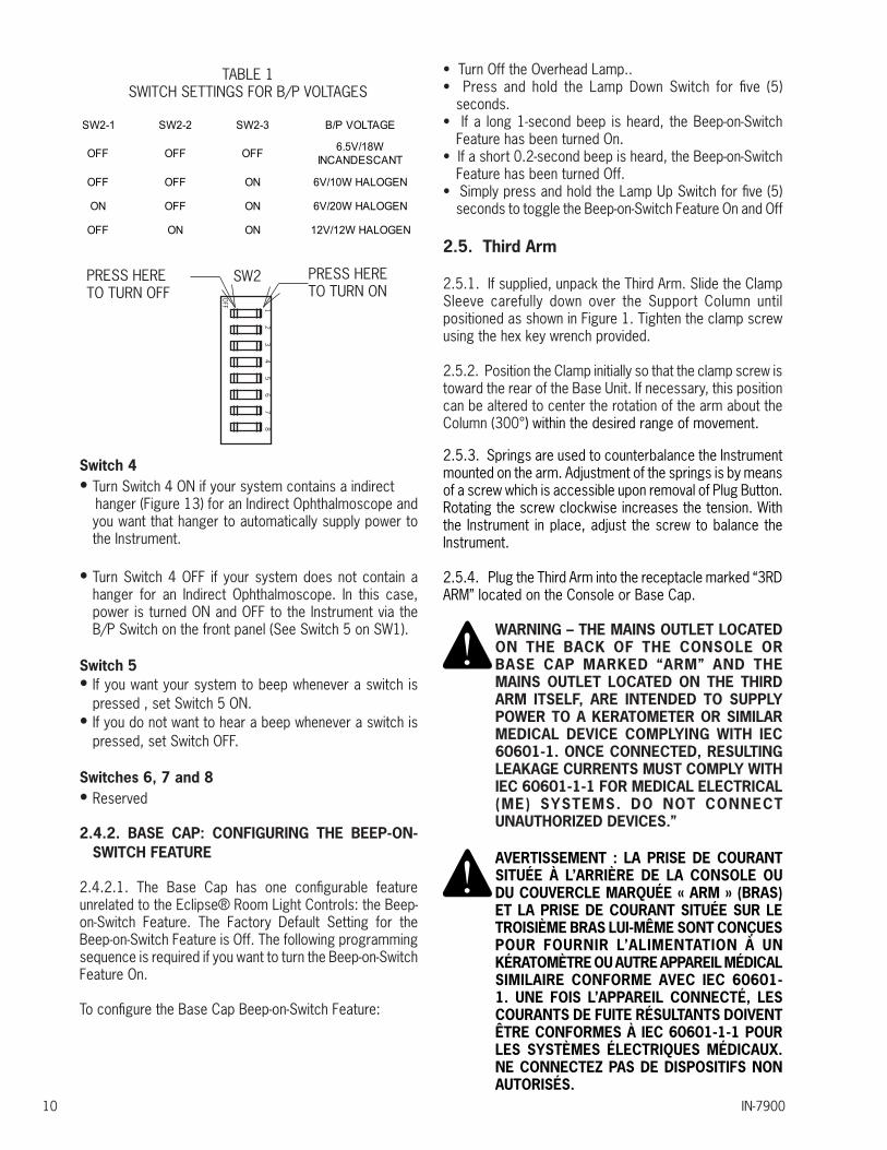
SW2-1 SW2-2 SW2-3 B/P VOLTAGE
OFF OFF OFF 6.5V/18WINCANDESCANT
OFF OFF ON 6V/10W HALOGEN
ON OFF ON 6V/20W HALOGEN
OFF ON ON 12V/12W HALOGEN
TABLE 1SWITCH SETTINGS FOR B/P VOLTAGES
OFF 1 2 3 4 5 6 7 8
PRESS HERETO TURN OFF
PRESS HERETO TURN ON
SW2
Switch 4• Turn Switch 4 ON if your system contains a indirect hanger (Figure 13) for an Indirect Ophthalmoscope and
you want that hanger to automatically supply power to the Instrument.
• Turn Switch 4 OFF if your system does not contain a hanger for an Indirect Ophthalmoscope. In this case, power is turned ON and OFF to the Instrument via the B/P Switch on the front panel (See Switch 5 on SW1).
Switch 5 • If you want your system to beep whenever a switch is
pressed , set Switch 5 ON.• If you do not want to hear a beep whenever a switch is
pressed, set Switch OFF.
Switches 6, 7 and 8• Reserved
2.4.2. BASE CAP: CONFIGURING THE BEEP-ON-SWITCH FEATURE
2.4.2.1. The Base Cap has one configurable feature unrelated to the Eclipse® Room Light Controls: the Beep-on-Switch Feature. The Factory Default Setting for the Beep-on-Switch Feature is Off. The following programming sequence is required if you want to turn the Beep-on-Switch Feature On.
To configure the Base Cap Beep-on-Switch Feature:
IN-7900 11
2.6. Refractor Arm - Dual Lock
2.6.1. Unpack the Refractor Arm. Slide the Clamp Sleeve carefully down over the Support Column until positioned as shown in Figure 1. Tighten the clamp screw securely, using the hex key wrench provided.
2.6.2. Note that the chrome Plug Button in the front of the Refractor Arm Assembly covers the counterbalance spring adjusting screw. If necessary, after the Instrument is attached to the Refractor Arm, remove this button and adjust the screw, turning it clockwise to increase tension. Optimum adjustment is reached when the Refractor Arm barely supports the weight at the upper limit of its travel. The Refractor Arm will support Instruments weighing a maximum of 20 pounds.
2.7. Overhead Lamp
2.7.1. Unpack the Overhead Lamp Assembly. Remove the small screw near the top of the Support Column. Feed the Lamp Cord and Coiled Extension Cord into the top of the Support Column until the Overhead Lamp can be inserted into the Column. Replace the screw previously removed.
2.7.2 Remove the Support Tube Pin (Item 11, Fig. 20) to allow the Overhead Lamp Cord to drop through the Support Column. Replace the Support Pin, being careful not to pinch the Overhead Lamp Cord. Insert the plug from the Overhead Lamp Extension Cord into the matching connector hanging down from the rear of the Console.
2.8. Final Assembly
2.8.1. Console/Base Cap
If an additional Instrument is to be connected to the Binding Posts or if any auxiliary equipment is to be plugged into the outlets, make these connections at this time.
2.9 Slit Lamp Arm
2.9.1. After slit lamp arm is unpacked and set into place, the option of changing the instrument stand can be done at this time. For example if the unit is order as a right-handed and needed to be changed to left-handed unit; follow the listed instructions below.
2.9.1.1 To convert the Slit Lamp Arm to a left-handed unit, remove the four (4) #8-32 Screws that hold the Cover Plates with the Outlet and Rocker Switch. Carefully pull the Plates off of the Upper Arm. Loosen the center Screw holding the two plates together but do not completely remove it. Pull the two Plates apart and rotate them so the Outlet and Rocker Switch are now on the opposite side of the Upper Arm.
Be careful not to pinch any wires between the Plates and the Upper Arm when making this change.
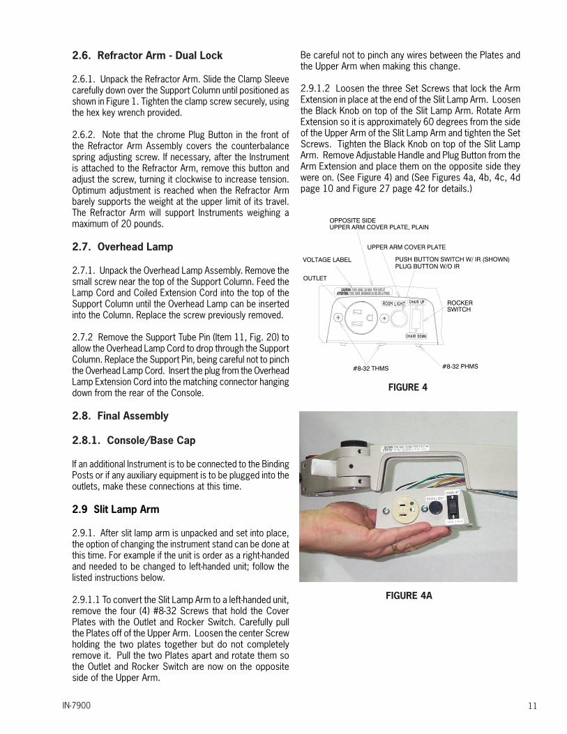
2.9.1.2 Loosen the three Set Screws that lock the Arm Extension in place at the end of the Slit Lamp Arm. Loosen the Black Knob on top of the Slit Lamp Arm. Rotate Arm Extension so it is approximately 60 degrees from the side of the Upper Arm of the Slit Lamp Arm and tighten the Set Screws. Tighten the Black Knob on top of the Slit Lamp Arm. Remove Adjustable Handle and Plug Button from the Arm Extension and place them on the opposite side they were on. (See Figure 4) and (See Figures 4a, 4b, 4c, 4d page 10 and Figure 27 page 42 for details.)
OUTLET
PUSH BUTTON SWITCH W/ IR (SHOWN)
ROCKER
#8-32 PHMS
VOLTAGE LABEL
#8-32 THMS
UPPER ARM COVER PLATE
OPPOSITE SIDEUPPER ARM COVER PLATE, PLAIN
PLUG BUTTON W/O IR
SWITCH
FIGURE 4
FIGURE 4A

IN-790012
FIGURE 4B
FIGURE 4C
FIGURE 4D
Reference to changing the Instrument Standfrom a right-handed to a left-hand unit.
2.10. Chair Assembly
2.10.1 The chair control switches located on the Floor Unit may control any Reliance® low voltage chair. Refer to the chair’s Installation and Operatiing Instructions for unpacking and assembling the chair.
2.10.2. A Chair Control Cable is provided to control the vertical movement of the Chair Base from the Floor Unit. One end of the cable is to be inserted into the black circular receptacle on the Outlet Plate Assembly. See Figure 4. The other end of the cable is to be inserted into the mating receptacle marked “CHAIR CONTROL CABLE” in the rear of your Reliance® chair.
CAUTION-“Accessory equipment connected to analog and digital interfaces must be certified according to the respective IEC standards (i.e. IEC 60950 for data processing equipment and IEC 60601-1 for medical equipment). Furthermore, all configurations shall comply with IEC 60601-1-1 for medical equipment systems. Anyone who connects additional equipment to the Signal Input Part (SIP) or Signal Output Part (SOP) configures a medical system, and is therefore responsible that the system complies with the requirements of IEC 60601-1-1. If in doubt, consult the Technical Service Department, or your local “Reliance”® Distributor.”
PRÉCAUTION : L’équipement accessoire connecté aux interfaces analogues et digitales doit être certifié selon les normes IEC respectives (c.-à-d., IEC 60950 pour l’équipement de traitement de données et IEC 60601-1 pour l’équipement médical). De plus, toutes les configurations doivent être conformes à IEC 60601-1-1 pour les systèmes électriques médicaux. Quiconque connecte de l’équipement supplémentaire à la partie entrée de signal ou à la partie sortie de signal configure un système médical et est par conséquent responsable de la conformité du système avec les exigences de IEC 60601-1-1. En cas de doute, consultez le service technique ou votre distributeur Reliance® local.

IN-7900 13
FIGURE 5
WARNING- THE MAINS OUTLET LOCATED ON THE OUTLET PLATE ASSEMBLY IS INTENDED TO SUPPLY POWER TO A RELI-ANCE® PATIENT EXAMINATION CHAIR OR SIMILAR MEDICAL DEVICE COMPLYING WITH IEC 60601-1. ONCE CONNECTED, RESULTING LEAKAGE CURRENTS MUST COMPLY WITH IEC 60601-1-1 FOR MEDI-CAL ELECTRICAL (ME) SYSTEMS. DO NOT CONNECT UNAUTHORIZED DEVICES.”
AVERTISSEMENT : LA PRISE DE COURANT SITUÉE SUR L’ASSEMBLAGE DE PLAQUE DE COURANT EST CONÇUE POUR FOURNIR L’ALIMENTATION À UNE CHAISE D’EXAMEN DE PATIENT RELIANCE® OU À UN DISPOSITIF MÉDICAL SIMILAIRE CONFORME À IEC 60601-1. UNE FOIS L’APPAREIL CONNECTÉ, LES COURANTS DE FUITE RÉSULTANTS DOIVENT ÊTRE CONFORMES À IEC 60601-1-1 POUR LES SYSTÈMES ÉLECTRIQUES MÉDICAUX. NE CONNECTEZ PAS DE DISPOSITIFS NON AUTORISÉS.
2.11. Miscellaneous
2.11.1. When attaching an instrument to the Slit Lamp Arm, note the Thrust Bearing which should be in place between the instrument and the arm. See Figure 4.
2.11.2. Proper balance of an Instrument on the Slit Lamp Arm is achieved by adding or removing counter-balance weights as shown in Figure 5. See Table 2 for weight settings.
2.11.3. Finally, plug the power cord into a wall receptacle and check all electrical functions as described in the Operating Instructions. If all functions are normal, attach the Base Unit Rear Cover.
2.11.4. To disconnect power from the Instrument Stand, unplug power cord from wall receptacle.
3. OPERATING INSTRUCTIONS
3.1. Slit Lamp Arm
3.1.1. The Slit Lamp Arm is counterbalanced by means of weights and all its movements are controlled manually.
3.1.2. The vertical lock for this arm is controlled by the Lock Release Lever located under the Slit Lamp Arm. (See Figure 1). Grip the Slit Lamp Arm and depress the Lock Release Lever to unlock the Slit Lamp Arm. Releasing the Lock Release Lever will lock vertical travel in both directions.
WARNING: SLIT LAMP ARM WILL RISE ABRUPTLY IF RELEASE LEVER IS DE-PRESSED AND ARM IS NOT COUNTER-BALANCED.
AVERTISSEMENT : LE BRAS DE LA LAMPE À FENTE SE LÈVERA ABRUPTEMENT SI LE LEVIER DE DÉGAGEMENT EST PRESSÉ ET QUE LE BRAS N’EST PAS CONTREBALANCÉ.
3.1.3. Incremental weights are added or removed to achieve proper balance in accordance with the Weight Settings-Slit Lamp Arm chart. (See also Figure 5).
3.1.4. The knob under the innermost pivot point of the Slit Lamp Arm (Figure 1) is to restrain rotation of the complete arm assembly. The knob at the intermediate joint on the Slit Lamp Arm locks rotation of the outer arm section. The knob directly under the Slit Lamp locks rotation of the Instrument about its pivot point.
LEVELINGSLEEVE
OUTERMOSTHANDLE
SET SCREWS(6)
BEARINGS
OUTER ARM
SLIT LAMPTABLE
FIGURE 6
IN-790014
3.1.6. The outermost Handle can be adjusted to any preferred, locked position. Simply pull out on handle, rotate as desired, and release.
3.1.7. The Outer Arm contains an outlet for Instrument power, and a Rocker Switch to control vertical movement of the chair. The Chair Control Cable (Item 17, Figure 20) must be installed. (Refer to Section 2.9). Depress the “UP” arrow on the switch to raise the chair. Depress the “Down” arrow to lower the chair.
WARNING- THE MAINS OUTLET LOCATED ON THE SLIT LAMP ARM IS INTENDED TO SUPPLY POWER TO A SLIT LAMP COMPLYING WITH IEC 60601-1. ONCE CONNECTED, RESULTING LEAKAGE CURRENTS MUST COMPLY WITH IEC 60601-1-1 FOR MEDICAL ELECTRICAL (ME) SYSTEMS. DO NOT CONNECT UNAUTHORIZED DEVICES.
AVERTISSEMENT : LA PRISE DE COURANT SITUÉE SUR LE BRAS DE LA LAMPE À FENTE EST CONÇUE POUR FOURNIR L’ALIMENTATION À UNE LAMPE À FENTE CONFORME À IEC 60601-1. UNE FOIS L’APPAREIL CONNECTÉ, LES COURANTS DE FUITE RÉSULTANTS DOIVENT ÊTRE CONFORMES À IEC 60601-1-1 POUR LES SYSTÈMES ÉLECTRIQUES MÉDICAUX. NE CONNECTEZ PAS DE DISPOSITIFS NON AUTORISÉS.
NOTE: Switch action is momentary; but may be programmed to function as maintained depending on the chair model. See chair manual for programming instructions.
REMARQUE : L’action de l’interrupteur est « momentané », mais peut être programmé pour fonctionner comme « maintenu » selon le modèle de chaise. Consultez le manuel de chaise pour les instructions de programmation.
3.2. Third Arm
3.2.1. Three knobs control all motions of this Arm Assembly. The one nearest the Column controls rotation about the Support Column. The lever at the pivot point of the Outer Arm controls both vertical movement and the rotation of the Outer Arm. The small knob in the Outer Arm controls rotation of the Instrument at the outermost pivot point.
3.2.2. Adjustment of the Spring counterbalance is as described in the Installation Instructions, Section 2.5.3.
INSTRUMENT GROSSWEIGHT-lbs.(kg)
INCREMENTAL WEIGHTS
12-16 ( 5.44-7.25) None
16-20 ( 7.25-9.0) Light
20-23 ( 9.0-10.43) Medium
23-25 ( 10.43-11.34) Heavy
25-28 ( 11.34-12.7) Light, Medium
28-30 ( 12.7-13.6) Light, Heavy
30-33 ( 13.6-14.97) Medium, Heavy
33-35 ( 14.97-15.88) 2 Heavy
35-38 ( 15.88-17.24) Light, Medium, Heavy
38-40 ( 17.24-18.14) 1 Light, 2 Heavy
40-43 ( 18.14-19.5) 1 Medium, 2 Heavy
43-45 ( 19.5-20.41) 3 Heavy
45-48 ( 20.41-21.77) 1 Light, 1 Medium, 2 Heavy
48-50 ( 21.77-22.68) 1 Light, 3 Heavy
50-53 ( 22.68-24.04) 1 Medium, 3 Heavy
53-55 ( 24.04-24.95) 4 Heavy
55-58 ( 24.95-26.31) 1 Light, 1 Medium, 3 Heavy
58-60 ( 26.31-27.22) 1 Light, 4 Heavy
Table 2Weight Settings-Slip Lamp Arm Chart
3.1.5. The outer end of the Slit Lamp Arm contains a Leveling Sleeve and six set screws for field re-leveling of the Instrument, if necessary. A hex key wrench (1/8) and a small, accurate level will be required. Remove the Instrument from the table and refer to Figure 4.
WARNING- WITH INSTRUMENT REMOVED, ARM WILL RISE ABRUPTLY IF RELEASE LEVER IS DEPRESSED.
AVERTISSEMENT : L’INSTRUMENT ÉTANT RETIRÉ, LE BRAS DE LA LAMPE À FENTE SE LÈVERA ABRUPTEMENT SI LE LEVIER DE DÉGAGEMENT EST PRESSÉ.
The outermost Handle must be threaded into the Leveling Sleeve, but not tightened. Rotate the Slit Lamp Arm to the examining position and tighten the other (2) handles. It may be necessary to loosen several set screws to reposition screws securely and check level again.
FIGURE 7

IN-7900 15
3.3. Refractor Arm
3.3.1. If the Refractor Arm is of the dual lock style, the knob nearest the Support Column controls the clamp for locking rotation of the entire Refractor Arm Assembly about the column. The lever locks both vertical movement and rotation of the Outer Arm.
3.3.2. Refer to the Installation Instructions 2.6 for the method of adjusting the counterbalancing spring.
WARNING – TIP-OVER HAZARD: NEVER GROUP THREE INSTRUMENT ARMS TOGETHER ON ONE SIDE OF THE STAND. DISTRIBUTE INSTRUMENT WEIGHT AS EQUALLY AS PRACTICAL. AVOID FAST OR FORCEFUL MOVEMENT OF INSTRUMENT ARMS.
AV E R T I S S E M E N T : R I S Q U E D E BASCULEMENT. NE REGROUPEZ JAMAIS LES TROIS BRAS D’ INSTRUMENTS ENSEMBLE SUR UN CÔTÉ DU SUPPORT. DISTRIBUEZ LE POIDS DES INSTRUMENTS AUSSI ÉGALEMENT QUE POSSIBLE. ÉVITEZ UN MOUVEMENT RAPIDE OU VIOLENT DES BRAS D’INSTRUMENTS.
3.4. Overhead Lamp
3.4.1. Movements of the Overhead Lamp arms are controlled by friction and spring-compensated joints, each of which is adjustable. Tighten all three knobs with moderate hand pressure. This will allow you to move the Overhead Lamp easily. The Overhead Lamp should hold its position without repeated knob adjustments. The Overhead Lamp has an ON/OFF switch located at the top of the head, which can be controlled separately from the Instrument Stand.
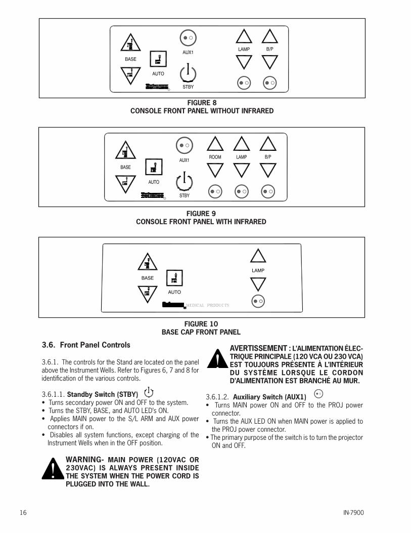
3.5. Instrument Console/Base Cap
3.5.1. The Instrument Console or Base Cap contains electrical controls for the entire Unit. Refer to Figure 6, 7, and 8 for the location of controls and other parts.
3.5.2. Hand Instrument Wells - Rechargeable Battery Type (Console only)
3.5.2.1. The Rechargeable Battery Well is internally connected to the charging circuit at the factory and will charge Instrument 3.5V NiCd batteries as long as the Instrument handle is fully seated in the well.
3.5.2.2. An indicator light (LED), located below each rechargeable well is supplied as a visual aid for determining that Instrument is properly seated in the well and is recharging.
WARNING: RECHARGEABLE BATTERY WELLS HAVE BEEN TESTED WITH “WELCH ALLYN LI-ION BATTERY HANDLES” AND FOUND TO BE COMPATIBLE. LI-ION BATTERY HANDLES FROM OTHER MANUFACTURERS HAVE NOT BEEN TESTED AND CANNOT BE RECOMMENDED AT THIS TIME.
AVERTISSEMENT : LES COMPARTIMENTS POUR BATTERIE RECHARGEABLE ONT ÉTÉ TESTÉS AVEC LES « MANETTES DE BATTERIE LITHIUM ION WELCH ALLYN » ET ONT ÉTÉ DÉCLARÉS COMPATIBLES. LES MANETTES DE BATTERIE LITHIUM ION D’AUTRES FABRICANTS N’ONT PAS ÉTÉ TESTÉES ET NE PEUVENT PAS ÊTRE RECOMMANDÉES EN CE MOMENT.
NOTE: “Welch Allyn offers an adapter that allows their Li-Ion Handles to operate correctly with Reliance® Rechargeable Battery Wells. Contact your Authorized Reliance® Distributor or Welch Allyn for details.”
REMARQUE : Welch Allyn offre un adaptateur qui permet à leurs manettes lithium ion de fonctionner correctement avec les compartiments de batterie rechargeable Reliance®. Contactez votre distributeur autorisé Reliance® ou Welch Allyn pour plus de détails.
CAUTION-The lamp inside the Rechargeable Instrument must be turned off before inserting the Handle into the Well. Handles will charge continuously as long as the power supply cord is attached to the equipment.
PRÉCAUTION : La lampe à l’intérieur de l’instrument rechargeable doit être désactivée avant d’insérer la manette dans le compartiment. Les manettes se chargeront continuellement aussi longtemps que le cordon d’alimentation est fixé à l’équipement.
IN-790016
AUTO
BASE
LAMP
FIGURE 8CONSOLE FRONT PANEL WITHOUT INFRARED
FIGURE 10BASE CAP FRONT PANEL
FIGURE 9CONSOLE FRONT PANEL WITH INFRARED
3.6. Front Panel Controls
3.6.1. The controls for the Stand are located on the panel above the Instrument Wells. Refer to Figures 6, 7 and 8 for identification of the various controls.
3.6.1.1. Standby Switch (STBY) • Turns secondary power ON and OFF to the system.• Turns the STBY, BASE, and AUTO LED’s ON.• Applies MAIN power to the S/L ARM and AUX power
connectors if on.• Disables all system functions, except charging of the
Instrument Wells when in the OFF position.
WARNING- MAIN POWER (120VAC OR 230VAC) IS ALWAYS PRESENT INSIDE THE SYSTEM WHEN THE POWER CORD IS PLUGGED INTO THE WALL.
AVERTISSEMENT : L’ALIMENTATION ÉLEC-TRIQUE PRINCIPALE (120 VCA OU 230 VCA) EST TOUJOURS PRÉSENTE À L’INTÉRIEUR DU SYSTÈME LORSQUE LE CORDON D’ALIMENTATION EST BRANCHÉ AU MUR.
3.6.1.2. Auxiliary Switch (AUX1)• Turns MAIN power ON and OFF to the PROJ power
connector.• Turns the AUX LED ON when MAIN power is applied to
the PROJ power connector.• The primary purpose of the switch is to turn the projector
ON and OFF.
WARNING- THE MAIN OUTLET LOCATED ON THE BACK OF THE CONSOLE OR BASE CAP MARKED “PROJ” IS INTENDED TO SUPPLY POWER TO A PROJECTOR OR SIMILAR MEDICAL DEVICE COMPLYING WITH IEC 60601-1. ONCE CONNECTED, RESULTING LEAKAGE CURRENTS MUST COMPLY WITH IEC 60601-1-1 FOR MEDICAL ELECTRICAL (ME) SYSTEMS. DO NOT CONNECT UNAU-THORIZED DEVICES.
AVERTISSEMENT : LA PRISE DE COURANT SITUÉE À L’ARRIÈRE DE LA CONSOLE OU DU COUVERCLE DE LA BASE MARQUÉE « PROJ » EST CONÇUE POUR FOURNIR L’ALIMENTATION À UN PROJECTEUR OU AUTRE APPAREIL MÉDICAL SIMILAIRE CONFORME AVEC IEC 60601-1. UNE FOIS L’APPAREIL CONNECTÉ, LES COURANTS DE FUITE RÉSULTANTS DOIVENT ÊTRE CONFORMES À IEC 60601-1-1 POUR LES SYSTÈMES ÉLECTRIQUES MÉDICAUX. NE CONNECTEZ PAS DE DISPOSITIFS NON AUTORISÉS.
3.6.1.3. Room Switch (ROOM)• Dual-Zone turns the ROOM Lights OFF or ON to a pre-
programmed intensity.• Single-Zone turn ROOM Lights OFF or full ON.
3.6.1.4. Room Down Switch• Decreases the intensity of the ALL room light(s).
3.6.1.5. Room Up Switch• Increases the intensity of the ALL room lights(s).
3.6.1.6. Lamp Switch (LAMP)• Turns the Overhead Lamp ON and OFF.• Turns the lamp ON at 50% intensity when the switch is
pressed for the first time after the system’s power cord is plugged into the wall. Afterwards, the light will turn ON at its previous intensity level..
• Turns the LAMP LED ON when power is applied to the Overhead Lamp.
3.6.1.7. Lamp Down Switch• Decreases the intensity of the Overhead Lamp.
3.6.1.8. Lamp Up Switch• Increases the intensity of the Overhead Lamp.
3.6.1.9. Binding Post Switch (B/P)• The B/P Switch is enabled when Switch 5 of SW2 is
turned OFF. See Table 1.• When enabled, turns power to the binding Posts (Indirect
Ophthalmoscope) ON and OFF.• Turns the B/P LED ON when power is applied to the
IN-7900 17
Ophthalmoscope.• When disabled, the B/P Switch has no function. Power to
the Ophthalmoscope is controlled by the optional Indirect Hanger Assembly.
3.6.1.10. B/P Down Switch• Decreases the intensity of the Indirect Ophthalmoscope.
3.6.1.11. B/P Up Switch• Increases the intensity of the Indirect Ophthalmoscope.
3.6.1.12. Chair Base Up Switch• Causes the Chair Base to raise.
3.6.1.13. Chair Base Down Switch• Causes the Chair Base to lower
3.6.1.14. Auto Switch• On a low voltage 980, 7000, 710 or FX920 Chair, this
switch causes the Chair Base to lower to its lowest position and the Chair Top to move to its full upright position.
Hanger Switch• Affects the room lights and is programmable.• See Switch 4 on Switchpack #2 in Section 2.4, Configur-
ing the System of this manual for details.• See section 3.8.3 for Programming Instructions.
Slit Lamp Switch• Affects the room lights and is programmable.• See section 3.8.3 for Programming Instructions.• See Switch 6 on Switchpack #1 in the Programming
Instructions Section of this manual for details.• Push button at the beginning of Slit Lamp examination,
then push button again after examination is complete.
Well #1• Controls room light(s) when the rechargeable instrument
is removed from well.• When the instrument is returned to the well, the room lights
return to Scene #1. See section 3.8.3 for Programming Instructions.
• See Switch 2 on Switchpack #1.
Well #2• Controls room light(s) when the rechargeable instrument
is removed from the well.• When the instrument is returned to the well, the room lights
return to Scene #1. See section 3.8.3 for Programming Instructions.
• See Switch 3 on Switchpack #1.
IN-790018
Well #3• Controls room light(s) when the rechargeable instrument
is removed from the well.• When the instrument is returned to the well, the room lights
return to Scene #1. See section 3.8.3 for Programming Instructions.
• See Switch 4 on Switchpack #1.
• On a low voltage 520, 522, 6200 or FXM920 Chair, this switch causes the Chair Base to lower to its lowest position.
CAUTION- The chair will continue to move after this switch is released. To STOP chair movement, press this switch a second time or press the STOP switch located on the side of the chair back.
PRÉCAUTION : La chaise continue de se déplacer après que cet interrupteur est relâché. Pour ARRÊTER le mouvement de la chaise, appuyez sur cet interrupteur une deuxième fois ou appuyez sur l’interrupteur STOP (ARRÊT) situé sur le côté du dossier de la chaise.
3.7. Fuses
WARNING: DISCONNECT EQUIPMENT FROM MAIN INPUT POWER BEFORE PRO-CEEDING WITH ELECTRICAL INSPECTIONS OR MAINTENANCE.
AVERTISSEMENT : DÉCONNECTEZ L’ÉQUIPEMENT DE L’ALIMENTATION É L E C T R I Q U E P R I N C I PA L E AV A N T DE PROCÉDER À DES INSPECTIONS ÉLECTRIQUES OU À DE L’ENTRETIEN.
CAUTION: Replace fuse(s) as marked. All fuses must be replaced with a fuse of the same size and rating. Refer to the Wire Diagrams at the end of this Manual.
PRÉCAUTION : Remplacez le(s) fusible(s) comme indiqué. Tous les fusibles doivent être remplacés par un fusible de la même dimension et de la même valeur. Se référer aux schémas de câblage à la fin de ce manuel.
3.7.1. Floor Units contain two fuses located inside the AC Input Module on the Outlet Plate Assembly.
3.7.2. Console and Base Cap contain no additional fuses.
3.7.3. Fuse Replacement (AC Input Module) Unplug the power cord from the Floor Unit. With a tool similar to a small common screwdriver, unsnap the locking tab on the bottom of the Fuse Drawer. Remove and examine the fuses. Replace as necessary. See Figure 9.
Method for removing Fuse Drawer:
1. The Fuse Drawer is located above the power cord.
2. Remove the Power Cord.
3. Place a small bladed screwdriver behind flap and pry out. The Fuse Drawer will come forward slightly.
CAUTION: To avoid a bind of the Fuse Drawer within the AC Input Module, never install the Fuse Drawer into the AC Input Module without fuses.
PRÉCAUTION : Pour éviter que le tiroir à fusible reste bloqué dans le module d’entrée CA, n’installez jamais le tiroir à fusible à l’intérieur du module d’entrée CA sans fusibles.
FIGURE 11
the Eclipse® Room Light Control System. Contact Technical Service for further as-sistance.
PRÉCAUTION : Les manettes de batterie lithium ion causeront un fonctionnement non désiré de l’éclairage de la pièce lorsque celui-ci est commandé par le système de commande d’éclairage de pièce Eclipse®. Contactez le service technique pour une assistance supplémentaire.
3.8.3. Configuring the Instrument Stand to Automatically Control Room Lights
When the user wants to turn on some function of the Instrument Stand, for example, turn the Slit Lamp or AUX1 Switch On, remove the Indirect Ophthalmoscope from the Hanger, or remove a battery-operated Instrument from a Charging Well, they typically intend to perform a specific examination upon the patient. The Eclipse® System allows the user to program the room lights to an intensity level that is suitable for that examination. When the Eclipse® System is used with a Console, the user can individually select which of the nine functions will control room lights by setting switches located on the circuit board. On the Base Cap, only two switches control room lights. These switches always send IR signals to the IR Receiver and this functionality cannot be disabled by switches on the circuit board.
3.8.3.1. Console: Configuring Dip Switches on the Circuit Board (SW1)
• To avoid any chance of an electrical shock, disconnect the Instrument Stand’s power cord from the wall outlet.
• Review Table 3. If you want one of the listed switches to automatically control room lights during an exam, turn the corresponding switch On. Otherwise, turn the switch Off. The Factory Default setting is Off.
• Reconnect the Instrument Stand to power.
SWITCHPACK #1 (SW1)
Switch 1• Turn Switch 1 OFF if your system contains a Single-Zone
Infrared Receiver.• Turn Switch 1 ON if your system contains a Three-zone
infrared receiver (Factory default setting).
Switch 2• Turn Switch 2 ON to enable Well #1 to affect room lights.• Turn Switch 2 OFF to disable Well #1 from affecting room
lights.
Switch 3• Turn Switch 3 ON to enable Well #2 to affect room lights.• Turn Switch 3 OFF to disable Well #2 from affecting room
lights.IN-7900 19
3.8. Eclipse ® Infra-red (IR) 3 Zone Room Light Control System
The Eclipse® IR Room Light Control System (Eclipse® System) is an option on the Instrument Stand and is available with a Console or Base Cap. The Eclipse® System allows you to control the exam room’s incandescent and/or florescent lights, and some LED lighting, directly from the Instrument Stand. In most cases, the Instrument Stand changes room lights “automatically” and to the intensity you have chosen for the exam you are about to perform.
The Eclipse® System adds two major components to your Instrument Stand: an IR Transmitter and an IR Receiver. The IR Transmitter snaps onto the top of the Instrument Stand’s Support Pole. It sends IR signals to the IR Receiver, just like your TV’s Remote Control Unit sends IR signals to your TV. The IR Transmitter should be pointed at the IR Receiver.
The IR Receiver mounts inside the exam room on the wall. Refer to the IR Receiver in Figure 15.
3.8.1. Three Zone System
3.8.1.1 A Zone refers to a bank of lights controlled by one room light switch. For example a room with a group of canned lights controlled by one switch and fluorescent controlled by another switch has two lighting zones. • Each zone has a dedicated raise and lower button toadjust the zone.• Each zone has a dedicated 7-LED bar graph for levelstatus. Percentage of light level and energy saved isdisplayed on the info screen.• All zone information has blue backlit LEDs. Backlight turnsoff when idle for 30 seconds.
3.8.2. Scenes
3.8.2.1 A Scene simply refers to the intensity of the room lights that has been pre-programmed into the Single or Dual-Zone IR Receiver. When the IR Transmitter sends a signal to the IR Receiver, that signal tells the IR Receiver which Scene to adjust the room lights to. Goto http://www.lutron.com/TechnicalDocumentLibrary/QSGRJ-xP_QSGR-xP_English_Install.pdf for Installation and Operation Instructions.
CAUTION- Li-Ion Battery Handles will cause unintended operation of the room lights when room lights are controlled by
FIGURE 12
IN-790020
OFF
12
34
56
78
ZONEWELL #1WELL #2WELL #3BINDING POSTS/L ARMAUXILIARYLAMP
SW1ENABLE-ON
PRESS HERETO TURN OFF
PRESS HERETO TURN ON
HRET E
ECLIPSE® ROOM LIGHT SYSTEM
TABLE 3 REAR VIEW OF CONSOLE ASSEMBLY
Switch 4• Turn Switch 4 ON to enable Well #3 to affect room lights.• Turn Switch 4 OFF to disable Well #3 from affecting room
lights.
Switch 5• If power to the Indirect Ophthalmoscope is controlled by
the B/P Switch on the front panel, turn Switch 5 ON if you want the B/P Switch to affect room lights.
• Turn Switch 5 OFF if you do not want the B/P Switch to affect room lights.
Switch 6• Turn Switch 6 ON to enable Slit Lamp Arm Switch to affect
room lights.• Turn Switch 6 OFF to disable Slit Lamp Arm Switch from
affecting room lights.
Switch 7• Turn Switch 7 ON to enable the AUX1 Switch to affect
room lights.• Turn Switch 7 OFF to disable the AUX1 Switch from
affecting room lights.
Switch 8• Turn Switch 8 ON to enable the LAMP Switch to affect
room lights.• Turn Switch 8 OFF to disable the LAMP Switch from
affecting room lights.
3.8.3.2. Base Cap: Configuring the Base Cap Software (The Base Cap Circuit Board does not contain Dip Switches.)
The Base Cap controls just two IR functions: • the Room Lights Switch on the Slit Lamp Arm, and
• the Hanger SwitchThese functions are always enabled and cannot be disabled by Dip Switches or software. However, you still need to configure the Base Cap to communicate with Single or Three-Zone IR Receiver. The Factory Default Setting is the Three-Zone IR Receiver. The following programming sequence is not required if a Three-Zone IR Receiver has been installed in your examination room.
To configure the Base Cap:• Turn Off the Overhead Lamp.• Press and hold the Overhead Lamp Up Switch for five
(5) seconds.• If a short 0.2-second beep is heard, the Base Cap has
been configured for a Single-Zone IR Receiver.• If a long 1-second beep is heard, the Base Cap has been
configured for a Three-Zone IR Receiver.• Simply press and hold the Lamp Up Switch for five (5)
seconds to toggle between the Single or Three-Zone IR Receiver.
**NOTE: When using a Base Cap, only these two switches** control room lights. These switches always send IR signals to the IR Receiver and this functionality cannot be disabled.
**REMARQUE : Lorsqu’un couvercle est utilisé, seulement ces deux interrupteurs** contrôlent l’éclairage de la pièce. Ces interrupteurs envoient des signaux IR au récepteur IR et cette fonctionnalité ne peut pas être désactivée.
3.8.3.3. Entering and Exiting Programming Mode Three-Zone IR Receiver
After your IR Receiver has been installed, only a few steps are required to enable your Instrument Stand to control room lights. In this example, let’s assume you want to dim the room lights when performing an examination using the Slit Lamp. In this case, a switch has been provided on the Slit Lamp Arm for controlling room lights during a Slit Lamp exam.
3.8.3.4. Entering Programming Mode Press and hold the top and bottom scene buttons simultaneously for 3 seconds. The LEDs in the scene buttons will scroll from top to bottom, confirming that you are in programming mode, and the info screen will display the main menu.
3.8.3.5. Exiting Programming ModePress and hold the top and bottom scene buttons simultaneously for 3 seconds. The info screen will go to Scene 1.
3.8.3.6. Navigating Menus in Programming Mode
FIGURE 13

IN-7900 21
3.8.3.7. Master Buttons
The Master buttons allow you to move through the menu choices. The current choice is highlighted on the info screen.
3.8.3.8. OK Button
The OK button chooses the current highlighted menu choice. This will either take you to the next menu or accept a setting you have selected. When the screen displays a Yes/No question, the OK button is “Yes”.
3.8.3.9. Timeclock Button
The Timeclock button functions as a “back” button during programming mode. Pressing the Timeclock button takes you back one step in the current menu. Pressing it repeatedly will eventually return you to the main menu, but will not exit programming mode. When the screen displays a Yes/No question, the Timeclock button is “No”..
3.8.3.10. Zone Setup
3.8.3.11. Assigning Load Types
1. Enter programming mode. 2. Use the Master buttons to highlight “Zone setup” and press the OK button to accept. 3. Use the Master buttons to highlight “Load type”. Press the OK button to accept. See “Setting Load Types” table on the next page. 4. Use the zone raise/lower buttons to choose the load type for that zone. See the list on the next page for supported load types. Press the OK button to accept. 5. The info screen will confirm that your load type has been saved. 6. Exit programming mode.
3.8.3.12. Assigning Non-Dim Load Types
Zones assigned to non-dim loads have three available configurations: • LOFO: Last On, First Off • FOFO: First On, First Off • FOLO: First On, Last Off • LOLO: Last On, Last Off • 60/40: On at 60%, off at 40% In scenes including dim and non-dim load types, if set up as “First” On/Off, non-dim loads will toggle before dim loads; if set up as “Last” On/Off, dim loads will toggle before non-dim loads. 1. Enter programming mode. 2. Use the Master buttons to highlight “Zone setup” and press the OK button to accept. 3. Use the Master buttons to highlight “Non-Dim Load type”. Press the OK button to accept. See “Setting Load Types” table on the next page. 4. Use the zone raise/lower buttons to choose the non
dim load type for that zone. (Zones not programmed as non-dim will be displayed as Unaffected.) Press the OK button to accept. 5. The info screen will confirm that your load type has been saved. 6. Exit programming mode.
3.8.3.13. Scene Setup
3.8.3.14. Setting Zone Levels, Fade Rates, and Shade Group Actions
1. Enter programming mode. 2. Use the Master buttons to highlight “Scene setup” and press the OK button to accept. 3. Use the Master buttons to highlight “Levels” to adjust lighting and/ or shade levels. Press the OK button to accept. Use the Master buttons to highlight the scene number of your desired scene. Press the OK button to accept. 4. Set each zone to the desired light level for this scene using the zone raise/lower buttons. The info screen will display the zone and percentage as you adjust it. To set a zone as unaffected, lower the light levels all the way to off, then hold the zone lower button for 3 seconds. The screen will display “---” and the three middle LEDs for the zone will be lit to indicate this zone is unaffected by the scene (the zone will not change when this scene is initiated). When all zones are at the desired level, press the OK button to accept. 5. Use the Master buttons to set the fade time for this scene. Press the OK button to accept. 6. Note: This step is applicable only if you have shades on your system. If you do not have or do not wish to set shade groups for this scene, press the OK button to skip this step. Set each shade group to the desired level for this scene. When all shade groups are at the desired level, press the OK button to accept. For shade programming, see the full installation and operation guide at www.lutron.com/qs. 7. The info screen will confirm that your scene has been saved. 8. Exit programming mode.
3.8.3.15. Pico Wireless Control Setup 1. Make sure the wireless mode of the GRAFIK Eye QS control unit is “Enabled”. 2. On the Pico wireless control, press and hold the top (on) and bottom (off) buttons for 3 seconds. The info screen on the GRAFIK Eye QS control unit will display the Pico wireless control options. Press the OK button on the GRAFIK Eye QS control unit to select the desired operation type for the Pico wireless control. 3. Assign the Pico wireless control a. To assign the Pico wireless control as a zone controller, use the Master buttons to select “Zone” and press the OK button to accept. Use the zone raise/

IN-790022
FIGURE 15THREE-ZONE RECEIVER
HANGER
BINDING POSTS
RHEOSTAT
FIGURE 16INDIRECT HANGER SWITCH
lower buttons for a zone to select a desired preset level, and then press the zone raise and lower buttons simultaneously for 1 second (until the zone LEDs flash at the programmed preset level). Repeat for all zones you wish to control with the Pico wireless control. OR b. To assign the Pico wireless control as a scene controller, use the Master buttons to select “Scene” and press the OK button to accept. Press and hold the top scene button on the GRAFIK Eye QS control unit for 3 seconds (until the scene LEDs flash). 4. On the Pico wireless control, press and hold the top and bottom buttons for 3 seconds until the LEDs on the GRAFIK Eye QS control unit stop flashing.
NOTE: The wireless signal has a range of 30 ft (9 m) through standard construction or 60 ft (18 m) line of sight.
REMARQUE : Le signal sans fil a une portée de 9 m (30 Ft) par construction standard ou de 18 m (60 Ft)
NOTE: A Fade Rate can also be programmed for each Scene. This is done at the IR Receiver. Refer to the Installer’s Guide provided with your IR Receiver.
REMARQUE : Un taux de fondu peut aussi être programmé pour chaque Scène. Ceci est effectué au récepteur IR. Se référer au guide de l’installateur fourni avec votre récepteur IR.
**NOTE: When using a Base Cap, only these two switches** control room lights. These switches always send IR signals to the IR Receiver and this functionality cannot be disabled.
**REMARQUE : Lorsqu’un couvercle est utilisé, seulement ces deux interrupteurs** contrôlent l’éclairage de la pièce. Ces interrupteurs envoient des signaux IR au récepteur IR et cette fonctionnalité ne peut pas être désactivée.
3.8.3.16. IR Receiver Installation Instructions
To install your IR Receiver, refer to the Installer’s Guide provided with your IR Receiver. The following diagrams and instructions are copied here for your convenience.
WARNING-YOUR IR RECEIVER MUST BE INSTALLED BY A QUALIFIED ELECTRICIAN IN ACCORDANCE WITH ALL APPLICABLE REGULATIONS. IMPROPER WIRING CAN RESULT IN PERSONAL INJURY OR DAMAGE TO YOUR IR RECEIVER OR OTHER EQUIPMENT.AVERTISSEMENT : VOTRE RÉCEPTEUR IF
FIGURE 14WIRELESS REMOTE CONTROL
DOIT ÊTRE INSTALLÉ PAR UN ÉLECTRICIEN QUALIFIÉ CONFORMÉMENT À TOUTES LES RÉGLEMENTATIONS APPLICABLES. UN CÂBLAGE INADÉQUAT PEUT CAUSER UNE BLESSURE OU ENDOMMAGER VOTRE RÉCEPTEUR IR OU D’AUTRE ÉQUIPEMENT.

IN-7900 23
P/N 3029099
Note: See the Installer’s Guide that came with your IR Receiver.
REMARQUE : Consultez le guide de l’installateur fourni avec votre récepteur IR.
NOTES:DESCRIPTION: RECEIVER, I.R., THREE-ZONE 120V-127V, 220-240V (NON CE) MANUFACTURER: LUTRON ELECTRONICS CO., INC.MODEL NO.: QSGRJ-3P-TWH
NO. OF ZONES: 3UNIT CAPACITY: 1600 WATTS/VA TOTAL (120V) 2400 WATTS/VA TOTAL (220-240V)
ENVIRONMENTAL: 32-104°F (0-40°C)POWER: INPUT POWER: 120V, 220-240VACZONE CAPACITY: STANDARD: 800 WATTS/VA PER ZONE (120V) 1200 WATTS/VA PER ZONE (220-240V)
LOAD TYPES: INCANDESCENT FLUORESCENT (DIM OR NON-DIM) REQUIRES RELIANCE P/N 29737 FLUOR. DIMMING BALLAST INTERFACE, 220-240V FLUORESCENT POWER MODULE 120-277V, 120V ONLY RELIANCE P/N 29736 OR LED INTERFACE, 10V 100-277V RELIANCE P/N 29738
FIGURE 18THREE-ZONE RECEIVER

IN-790024
FIGURE 19FLUORESCENT INTERFACE
P/N 17187
IN-7900 25
FIGURE 21
Note: See the Installer’s Guide that came with your IR Receiver.
REMARQUE : Consultez le guide de l’installateur fourni avec votre récepteur IR.
Installation Diagram: Three Zone Fluorescent ON/OFF120 VAC or 277 VAC
SPARE(Digital/Phase Control Zone)
Zone#3
Zone#1
120V/277VInput Feed
PHPM-PA-DV-WH120V or 277V
Phase-AdaptivePower Module
Dimensions:5.1"(H) x 6.3"(W) x 1.6"(D)
Zone#2
120V/277VInput Feed
PHPM-PA-DV-WH120V or 277V
Phase-AdaptivePower Module
Dimensions:5.1"(H) x 6.3"(W) x 1.6"(D)
QSGRJ-3P-TWHFaceplate Kit
3 Zone Preset Control(4 Gang US Backbox by Others)

IN-790026
FIGURE 22INSTALLATION DIAGRAM-THREE ZONE
12
34
12
AB
C
1 2 3 4 5 6 L N
12 AWG (4.0 mm )2
each terminal
120 - 127 V or 220 - 240 V Distribution Panel
Line Voltage/Mains Cables and Load Wiring
Incandescent load
Load controlled by power module or interface
Terminal labels:L: Hot/LiveN: Neutral : Ground1-6: Dimmed/Switched
line voltage outputs
Power module or interface
IN-7900 27
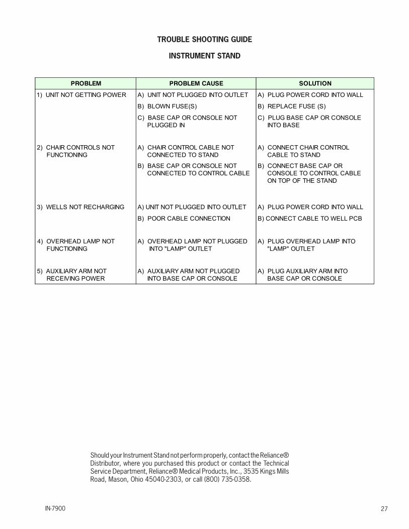
TROUBLE SHOOTING GUIDE
INSTRUMENT STAND
Should your Instrument Stand not perform properly, contact the Reliance® Distributor, where you purchased this product or contact the Technical Service Department, Reliance® Medical Products, Inc., 3535 Kings Mills Road, Mason, Ohio 45040-2303, or call (800) 735-0358.
PROBLEM PROBLEM CAUSE SOLUTION
1) UNIT NOT GETTING POWER A) UNIT NOT PLUGGED INTO OUTLET A) PLUG POWER CORD INTO WALL
B) BLOWN FUSE(S) B) REPLACE FUSE (S)
C) BASE CAP OR CONSOLE NOT PLUGGED IN
C) PLUG BASE CAP OR CONSOLE INTO BASE
2) CHAIR CONTROLS NOT FUNCTIONING
A) CHAIR CONTROL CABLE NOT CONNECTED TO STAND
A) CONNECT CHAIR CONTROL CABLE TO STAND
B) BASE CAP OR CONSOLE NOT CONNECTED TO CONTROL CABLE
B) CONNECT BASE CAP OR CONSOLE TO CONTROL CABLE ON TOP OF THE STAND
3) WELLS NOT RECHARGING A) UNIT NOT PLUGGED INTO OUTLET A) PLUG POWER CORD INTO WALL
B) POOR CABLE CONNECTION B) CONNECT CABLE TO WELL PCB
4) OVERHEAD LAMP NOT FUNCTIONING
A) OVERHEAD LAMP NOT PLUGGED INTO "LAMP" OUTLET
A) PLUG OVERHEAD LAMP INTO "LAMP" OUTLET
5) AUXILIARY ARM NOT RECEIVING POWER
A) AUXILIARY ARM NOT PLUGGED INTO BASE CAP OR CONSOLE
A) PLUG AUXILIARY ARM INTO BASE CAP OR CONSOLE
IN-7900
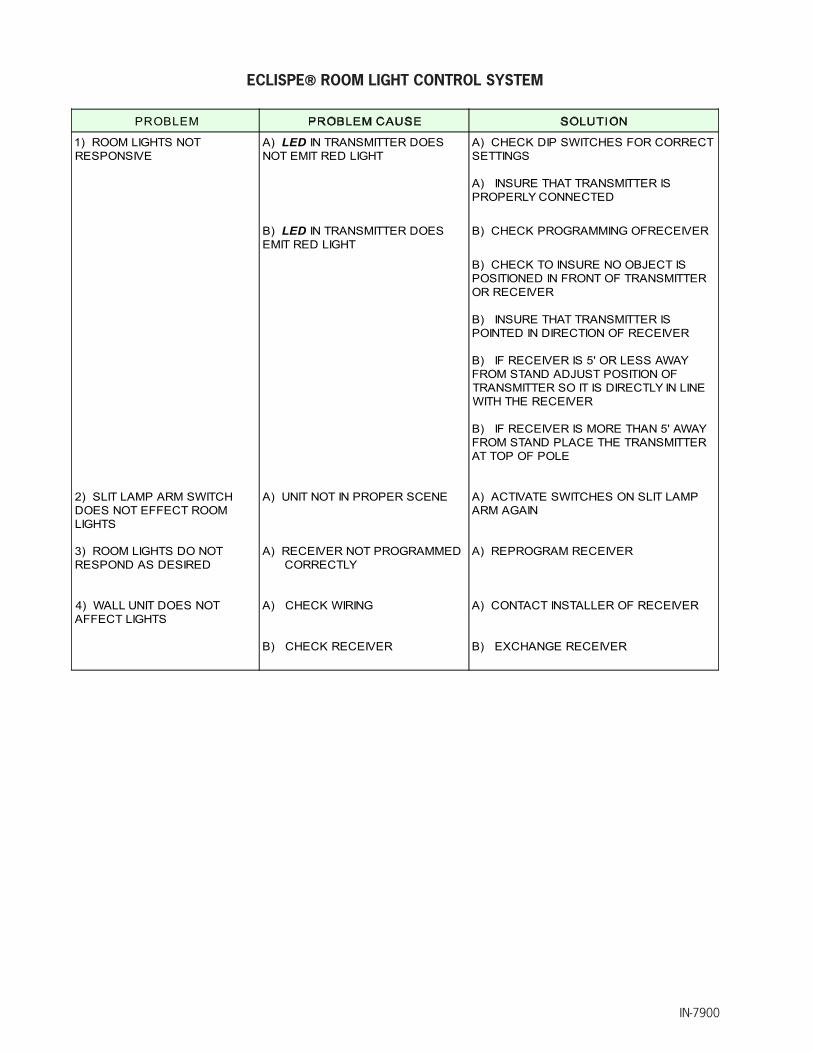
ECLISPE® ROOM LIGHT CONTROL SYSTEM
PROBLEM
1) ROOM LIGHTS NOTRESPONSIVE
A) LED IN TRANSMITTER DOESNOT EMIT RED LIGHT
A) CHECK DIP SWITCHES FOR CORRECTSETTINGS
A) INSURE THAT TRANSMITTER ISPROPERLY CONNECTED
B) LED IN TRANSMITTER DOESEMIT RED LIGHT
B) CHECK PROGRAMMING OFRECEIVER
B) CHECK TO INSURE NO OBJECT ISPOSITIONED IN FRONT OF TRANSMITTEROR RECEIVER
B) INSURE THAT TRANSMITTER ISPOINTED IN DIRECTION OF RECEIVER
B) IF RECEIVER IS 5' OR LESS AWAYFROM STAND ADJUST POSITION OFTRANSMITTER SO IT IS DIRECTLY IN LINEWITH THE RECEIVER
B) IF RECEIVER IS MORE THAN 5' AWAYFROM STAND PLACE THE TRANSMITTERAT TOP OF POLE
2) SLIT LAMP ARM SWITCHDOES NOT EFFECT ROOMLIGHTS
A) UNIT NOT IN PROPER SCENE A) ACTIVATE SWITCHES ON SLIT LAMPARM AGAIN
3) ROOM LIGHTS DO NOTRESPOND AS DESIRED
A) RECEIVER NOT PROGRAMMEDCORRECTLY
A) REPROGRAM RECEIVER
4) WALL UNIT DOES NOTAFFECT LIGHTS
A) CHECK WIRING
B) CHECK RECEIVER
A) CONTACT INSTALLER OF RECEIVER
B) EXCHANGE RECEIVER
IN-7900 29
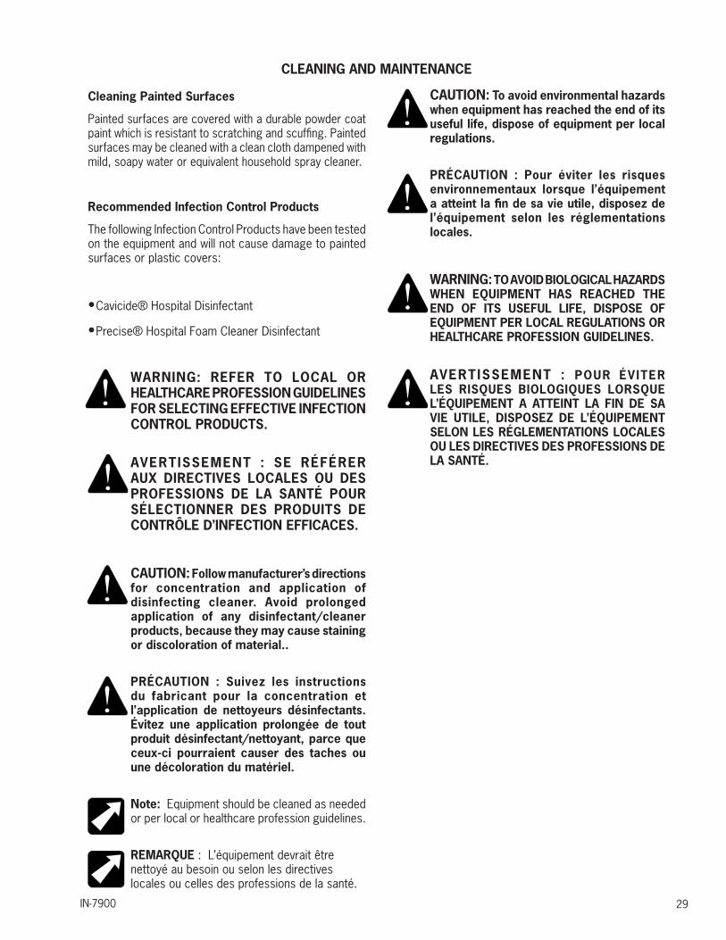
CLEANING AND MAINTENANCE
Cleaning Painted Surfaces
Painted surfaces are covered with a durable powder coat paint which is resistant to scratching and scuffing. Painted surfaces may be cleaned with a clean cloth dampened with mild, soapy water or equivalent household spray cleaner.
Recommended Infection Control Products
The following Infection Control Products have been tested on the equipment and will not cause damage to painted surfaces or plastic covers:
• Cavicide® Hospital Disinfectant
• Precise® Hospital Foam Cleaner Disinfectant
WARNING: REFER TO LOCAL OR HEALTHCARE PROFESSION GUIDELINES FOR SELECTING EFFECTIVE INFECTION CONTROL PRODUCTS.
AVERTISSEMENT : SE RÉFÉRER AUX DIRECTIVES LOCALES OU DES PROFESSIONS DE LA SANTÉ POUR SÉLECTIONNER DES PRODUITS DE CONTRÔLE D’INFECTION EFFICACES.
CAUTION: Follow manufacturer’s directions for concentration and application of disinfecting cleaner. Avoid prolonged application of any disinfectant/cleaner products, because they may cause staining or discoloration of material..
PRÉCAUTION : Suivez les instructions du fabricant pour la concentration et l’application de nettoyeurs désinfectants. Évitez une application prolongée de tout produit désinfectant/nettoyant, parce que ceux-ci pourraient causer des taches ou une décoloration du matériel.
Note: Equipment should be cleaned as needed or per local or healthcare profession guidelines.
REMARQUE : L’équipement devrait être nettoyé au besoin ou selon les directives locales ou celles des professions de la santé.
CAUTION: To avoid environmental hazards when equipment has reached the end of its useful life, dispose of equipment per local regulations.
PRÉCAUTION : Pour éviter les risques environnementaux lorsque l’équipement a atteint la fin de sa vie utile, disposez de l’équipement selon les réglementations locales.
WARNING: TO AVOID BIOLOGICAL HAZARDS WHEN EQUIPMENT HAS REACHED THE END OF ITS USEFUL LIFE, DISPOSE OF EQUIPMENT PER LOCAL REGULATIONS OR HEALTHCARE PROFESSION GUIDELINES.
AVERTISSEMENT : POUR ÉVITER LES RISQUES BIOLOGIQUES LORSQUE L’ÉQUIPEMENT A ATTEINT LA FIN DE SA VIE UTILE, DISPOSEZ DE L’ÉQUIPEMENT SELON LES RÉGLEMENTATIONS LOCALES OU LES DIRECTIVES DES PROFESSIONS DE LA SANTÉ.

IN-790030
PARTS LISTRELIANCE® MODEL 7900
OPHTHALMIC INSTRUMENT STAND
NOTE: When ordering parts, please:
1. Advise dealer or factory of model and serial number of Unit. These numbers are on the plate that is located at rear, near bottom, of Base Unit.
2. Specify color of painted parts. Painted parts have an asterisk(*) behind the part description.
REMARQUE : Lorsque vous commandez des pièces, veuillez :
1. Aviser le marchand ou l’usine du modèle et du numéro de série de l’appareil. Ces numéros se trouvent sur la plaque située en arrière, près du bas de la base.
2. Spécifier la couleur des pièces peintes. Les pièces peintes ont un astérisque (*) derrière la description de pièce.
Should your Instrument Stand not perform properly, or if replacement parts are needed, contact the Reliance® Distributor, where you purchased this product or contact the Technical Service Department, Reliance® Medical Products, Inc., 3535 Kings Mills Road, Mason, Ohio 45040-2303, or call (800) 735-0358.

IN-7900 31
FIGURE 23MODEL 7900 INSTRUMENT STAND ASSEMBLY
10
14
21
7
8
15
9
6
1318
3
4
11
22
19
219
16
1720
23
5
MODEL AND SERIALNUMBER PLATE
1
12
ITEM PART NO. DESCRIPTION ITEM PART NO. DESCRIPTION
1 Base Assembly* (See Figure 23 ) 12 0514780 Collar-Chrome
2 Slit Lamp Arm Assembly* (See Figure 28) 13 0722699 Sckt. H.S.S. 1/4 x 1/4
3 Console* (See Instrument Console Section) 14 1677399 Lens
4
2034392 Dual B/P Assembly 15 0715799 Round H.M.S #10 x 1/4
2034499 Twist Lock Hubbell Receptacle 16 1971599 Lock Cover
2034503 Cover Plate - P.CT* 17 1550599 Chair Control Cable
2040103 Indirect Receptacle Assembly18
1979592 Instrument Hanger Assembly
5 Refractor Arm Assembly* (See Figure 29) 2054092 Indirect Hanger Kit (I.R. Only)
6 Auxiliary (Third) Arm* (See Figure 30) 19 2035199 Locking Handle
7 525106 Lamp Assembly* 20 1659299 Power Cord Assembly
8 0541680 Snap Plug 21 1677499 Retaining Ring
91974599 Support Tube (Shown) 22 1682199 Caution Label
0537399 Column Stub 23 1969499 Lexan Shelf
10 1569799 Bulb-12vdc, 20w, Type G424
1568699 Chair Control Assembly (Not Shown)(used only to connect new stands to oldchairs)11 0503599 Support Pin
IN-790032
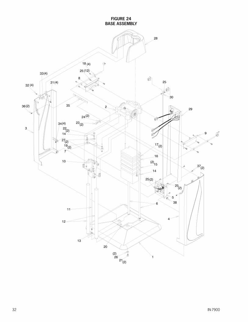
FIGURE 24BASE ASSEMBLY
IN-7900 33
ITEM PART NO. DESCRIPTION ITEM PART NO. DESCRIPTION
1 1598603 Base* 20 1974099 Bumper Pad
2 1966892 7900 Top Frame Assembly 21 0709399 Hex H.C.S. 1/2-13 x 3/4
3 1971192 LH Side Panel 22 0708299 Hex H.C.S. 3/8-16 x 3/4
4 1971092 RH Side Panel 23 0707199 Hex H.C.S. 5/16-18 x 1
5 Outlet Plate Assembly*(See Figure 25) 24 0728399 Washer - Lock 5/16 Split
6 0495599 Guide Rod 25 1734799 PHMS #10-32 x 3/8 W/Lock Washer
7 0825584 Lift Bar Assembly 26 0729299 Washer - 1/2
8 1971603 Side Panel Mounting Bracket - LH* 27 0728499 Washer - Lock 3/8 Split
9 1971703 SIde Panel Mounting Bracket - RH* 28 1971292 7900 Top Housing
10 Roller Frame Assembly*(See Figure 24) 29 Back Cover Assembly* (See Figure 26)
11 1225499 Lock Shaft ( in Item 10 ) 30 0591999 Cable Clamp
12 1598799 Support Column 31 2034999 PHMS #8-32 x 3/8 W/Lockwasher
13 2036099 1/2-20 Jam Nut 32 0705399 #8-32 Hex Nut
14 0825392 Weight & Cable Assembly-45 lbs 33 1975099 Side Panel Clamp
15 0548099 Counter Balance Weight - 10 lbs 34 0705599 #10-32 Keps Nut
16 0548199 Counter Balance Weight - 7.5 lbs 35 1976399 Face Plate - Mount Bar
17 0548299 Counter Balance Weight - 5 lbs 36 0821699 FHMS #8-32 x 3/8
18 0513199 Cable Clamp 37 2035099 THMS #10-32 x 3/8
19 0508599 3/8-16 Lock Nut 38 1282699 .625 Nylon Hole Plug
To order complete Base Assembly use P/N’s.
1967692 7900 Base Assembly- 120V* 1967792 7900 Base Assembly- 230V*
*Please specify paint color when ordering.
IN-790034
2
3
16
115
8
7
4
25
6
9
10
5
FIGURE 25ROLLER FRAME ASSEMBLY
To order complete Roller Frame Assembly use P/N.
1966192 7900 Roller Frame Assembly*
*Please specify paint color when ordering.
IN-7900 35
ITEM PART NO. DESCRIPTION ITEM PART NO. DESCRIPTION
1 1627295 Roller Frame*
13 1730699 Wiring Clip
2 1663299 Ball Bearing
3 1663699 Button H.C.S. 3/8 x 1
4 0513099 Clamp Bracket
5 0497299 Eccentric Bushing
6 0789399 SCKT H.C.S. 5/16 x 1-1/4
7 0728499 Lockwasher - 3/8 Split
8 0729599 Washer - 3/8
9 0730199 Washer - 5/16
10 0728399 Lockwasher - 5/16 Split
11 2725399 Upper Lockshoe
12 2725499 Lower Lockshoe
14 1222399 Spring
15 1770192 Coiled Cord Assembly-H.V. 3 Cond
16 1770292 Coiled Cord Assembly-L.V. 5 Cond
17 2724499 Ring
18 2724595 Sleeve
19 1225499 Lock Shaft
20 0297699 3/8 x 1-3/4 Nylon Pin
21 1730599 12 Circuit Cap
22 1225799 Lock Shoe Pin
23 0732599 Retaining Pin
24 0506899 Snap Bushing
25 0506199 Ball Bearing
18
2011
1214
17(2)
19 22
24
15
13
21
(2)23(4)
IN-790036
To order complete Outlet Plate Assembly use P/N’s.
1966992 Outlet Plate Assembly - 120V* 1967092 Outlet Plate Assembly - 230V* *Please specify paint color when ordering.
FIGURE 26OUTLET PLATE ASSEMBLY

IN-7900 37
ITEM PART NO. DESCRIPTION
1 1969803 Outlet Plate-7900*
21082899 Receptacle, Single 15A/125V, NEMA 5-15R (120V)
1733499 Receptacle, Single 15A/250V, NEMA 6-15R (230V)
3 1976799 Power Entry Module W/Filter
4 Fusedrawer, 2 Pole (in Item 3)
51682399 Fuse, 10A/250V (120V)
1634299 Fuse, 6.3A/250V (230 V)
6 0290299 T.H.M.S. #6-32 X3/8 - Phillips
7 1970599 Chair Control Cable - Internal
8 0904499 Cable Clamp 1/2 I.D.
9 1970692 AC Input Cord Set.
10 1977492 Ground Wire Assembly
11 0706599 Nut, Hex - #6-32 Keps
12 1977592 Ground Wire Assembly
13 1446099 Label- Chair Control
14 0591999 Cable Clamp - .50
151680399 Label, 6.3A/250V (120V)
1680499 Label, 4A/250V (230V)
16 1734799 #10-32 x 3/8 P.H.M.S. W/Lockwasher

IN-790038
11
9
12
10
1
87
56
24
3BROWN
GREEN/YELLOW
WHITE
BLACK
BLUE13
14
BLACKRED
15
!
To order complete Back Cover Assembly use P/N’s.
1967192 Back Cover Assembly - 120V* 1967292 Back Cover Assembly - 230V* 2047792 Back Cover Assembly - Base Cap - 120V* 2047892 Back Cover Assembly - Base Cap - 230V* *Please specify paint color when ordering.
FIGURE 27BACK COVER ASSEMBLY
IN-7900 39
ITEM PART NO. DESCRIPTION
1 1971403 Back Cover-7900*
2
2034692 Auxiliary Cable Assembly - Console - 120V
2034792 Auxiliary Cable Assembly - Console - 230V
2039992 Auxiliary Cable Assembly - Base Cap - 120V
2040092 Auxiliary Cable Assembly - Base Cap - 230V
3
2034503 Cover Plate* (Used With Base Cap)
2034392 Dual Binding Post Assembly
2040692 Hubbell Twist Lock Assembly
2054492 Indirect Hanger Plate Assembly
4 0302099 T.H.M.S. #6-32 X 1/2 - Phillips
5 0824399 T.H.M.S. #8-32 X 3/8 - Phillips
6 1682699 Label - Arm & Projector
71680199 Label - 2A Max. - 120V
1680299 Label - 1A Max. - 230V
81680599 Label - Binding Post
2054399 Label - Indirect Hanger
9 1682199 Label - Caution Shock Hazard
10 1083199 Label - Caution Continuity
111682499 Label - T10A/250V (120V)
1622999 Label - T6.3A/250V (230V)
12 1682299 Label - Leakage Current
132034199 Dual Binding Posts
2034499 Twist Lock Hubbell
14
2034292 Binding Post Jumper Assembly
2046392 Hubbel l Twist Lock Jumper Assembly
2054692 Indirect Hanger Jumper
15 Model and Serial Number Label
IN-7900
FIGURE 28SLIT LAMP ARM ASSEMBLY

IN-7900 41
To order complete Slit Lamp Arm Assembly use P/N’s.
1965792 Slit Lamp Arm Assembly- W/O IR 1965892 Slit Lamp Arm Assembly- W/ IR 1965992 Slit Lamp Arm Assembly W.C.-W/O IR 1966092 Slit Lamp Arm Assembly W.C..-W/ IR
*Please specify paint color when ordering.
ITEM PART NO. DESCRIPTION ITEM PART NO. DESCRIPTION
11967403 Lower Arm Assembly-STD* 22 0513199 1/4 Cable Clamp
1967503 Lower Arm Assembly-W/C* 23 0722899 1/4-28 x 3/8 Sckt H.S.S.
21968092 Upper Arm Assembly-STD* 24 0297799 1/4-28 x 1/2 Sckt H.S.S.
1968192 Upper Arm Assembly-W/C*25
1680199 2A Max., 120v/60HZ - 120V Label
3 1442203 Arm Extension* 1680299 2A Max., 230V/50HZ - 230V Label
4 1222699 Handwheel 26 1720399 #10-24 x 1/2 Pan H.M.S. W/Lockwasher
51624799 Outlet, S.S. H.G.-15A/125V - 120V
271282699 Button Plug (W/O IR)
1731499 Outlet, S.S. H.G.-15A/250V - 230V 1730099 Pushbutton Switch (W/ IR)
6 0142695 Lever Bracket 28 1734899 Switch Cap W/ IR
7 1225299 Release Lever 29 1513699 Rocker Switch -S.P.D.T
8 1225399 Cable Slide 30 1445299 #10-24 x 3/8 Pan H.M.S.
9 2035199 Locking Handle 31 0295699 1/4-28 Jam Nut
101978699 Control Cable Assembly - STD 32 2734199 Cable Adapter Nut
1978799 Control Cable Assembly - W/C 33 0732599 3/8 Retaining Ring
111731599 8 Cond., Cable 18AWG - 48" - STD 34 0297899 1/4 Retaining Ring
1731599 8 Cond., Cable 18AWG - 45.5" - W/C 35 0716699 #10-24 x 1/2 Round H.M.S.
12 1221999 1/4 Dia. x 1-7/16 Pin 36 0923499 Thrust Bearing
13 0919280 Collar - Chrome 37 1412399 Thrust Washer
14 0961099 Washer, Thrust 38 0807799 1/4-20 x 3/8 Sckt H.C.S.
15 0843599 Truss H.M.S. #8-32 x 5/8 39 2933503 Upper Arm Cover Plate*
16 0688099 5/16 Plug Button 40 2933603 Upper Arm Cover Plate - Blank*
17 0536999 Hole Plug 41 1658699 #6-32 x .25 Pan M.H.S. W/Lockwasher
18 0506599 Washer, Thrust 42 2043499 Room Light Label ( With IR Only)
19 0506399 Bearing-Thrust 43 2043299 Up Label
20 1442199 Leveling Sleeve 44 2043399 Down Label
21 0920199 Pivot Pin 45 2074799 Label-Safe Working Load-60 lbs
IN-790042
7
1
2
3
4
5
9
10
11
13
14
15
33
17
17
19
20
2122
23
24
25
26
27
28
29
30
31
8
18
16
6
12
32
16
34
SERIALLABEL
FIGURE 29MODEL 5250 DUAL LOCK REFRACTOR ASSEMBLY

IN-7900 43
ITEM PART NO. DESCRIPTION ITEM PART NO. DESCRIPTION
1 1973603 Support Assembly* 18 0298299 Washer - .005
2 0950103 Clamp Sleeve* 19 0503295 Pivot Pin
3 0515203 Suspension-Lower Arm Assembly* 20 0501495 Spring Pin
4 0117803 Suspension-Upper Arm Assembly* 21 0512992 Spring Assembly
5 1975803 Front Housing Assembly* 22 0501699 Screw - Adjustment 5/16-18 x7
6 0789199 THMS #10-24 x 3/8 - Phils 23 0502980 Lock Link
7 2855799 Refractor Arm Cover* 24 1979299 Adjustable Handle
81144680 Instrument Arm - Standard 25 1113292 Lock Handle Assembly
1606380 Instrument Arm - Wheelchair 26 0506595 Thrust Washer
9 0732199 Retaining Ring 27 0508380 Pivot Screw
10 0802599 Set Screw - #10-24 x 1/4 28 0508699 Washer - 3/4
11 1144580 Arm Stud 29 0514399 Washer - 2 3/8
12 0503395 Bushing (Part of Item 5) 30 1526299 Screw - 1/4 -24
13 0387380 Plug Button31
0808799 Cap Screw - Standard
14 0291399 Lock Bolt 1702599 Adjustable Handle - Wheelchair
15 0508880 Bushing 32 0730199 .312 SAE Washer
16 0354899 Valve Rod Spring Washer 33 0729599 .375 SAE Washer
17 0503195 Pivot Pin 34 2074599 Label-Safe Working Load-20lbs
To order complete Dual Lock Refractor Assembly use P/N’s.
525010 Refractor Suspension Arm Assembly - Standard (Dual Lock Refractor Arm) 525011 Refractor Suspension Arm Assembly - Wheelchair (Dual Lock Refractor Arm)
*Please specify paint color when ordering.

IN-790044
32
10
412
7
8
15
2223
18
11
1920
21
28
12
265
9
13
29
30
3
172
24
37
1
25
31 3332 (2)
34
356
39
39
40
38
14
1427
32
(2)
3637(2)
16
(2)
43
FIGURE 30MODEL 5380 AUXILIARY (3RD) ASSEMBLY
IN-7900 45
ITEM PART NO. DESCRIPTION ITEM PART NO. DESCRIPTION
1 1974103 Support*
23 0536799 Wire Clip
2 1974303 Clamp Sleeve*
3 0541803 Lower Arm Assembly*
4 0541903 Upper Arm Assembly*
5 1978403 Front Housing Assembly*
6 1750203 Swing Arm Assembly*
7 0541792 Spring Anchor Assembly
8 0119585 Spring Anchor
9 0919280 Collar
10 2855899 Cover, Third Arm*
11 0732399 Retaining Ring
12 0532592 Lock Link Assembly
13 0807799 1/4-20 x 3/8 Sock't H.C.S.
14 0532999 Pivot Pin
15 0501699 Adjusting Screw
16 0514399 Nylon Washer
17 0808799 5/16-24 x 1 1/4 B.H.C.S
18 0291399 Lock Bolt
19
0506499 Thrust Bearing20
0537499 Thrust Washer
21 0387380 Plug Button
22 0536599 Tension Spring
24 1979299 Adjustable Handle
251082899 Outlet-Single H.G. - 120V
1733499 Outlet-Single H.G. - 230V
26 1113292 Lock Handle Assembly
27 1679999 Machine Screw
28 0506699 Thrust Washer
29 1701403 Cover*
30 0688099 Plug Button
31 2035199 Adjustable Handle
32 0789199 #10-24 x .38 R.H.M.S. - Phil
33 0513199 Cable Clamp
34 0302099 Mounting Screw
351680199 Label - 2A Max - 120V
1680299 Label - 1A Max - 230V
36 0508699 Washer-Nylon
37 0729599 Washer-Zinc
38 0536999 Hole Plug
39 0506599 Thrust Washer
40 0506399 Thrust Bearing
41 2074699 Label-Safe Working Load-50lbs
42 2074499 Label-Consult Accompanying Doc
43 0728299 Washer - Split Lock 1/4
To order complete Auxiliary (3rd) Arm Assembly use P/N’s.
538011 Auxiliary (3rd) Arm Assembly - AC Plug*
*Please specify paint color when ordering.
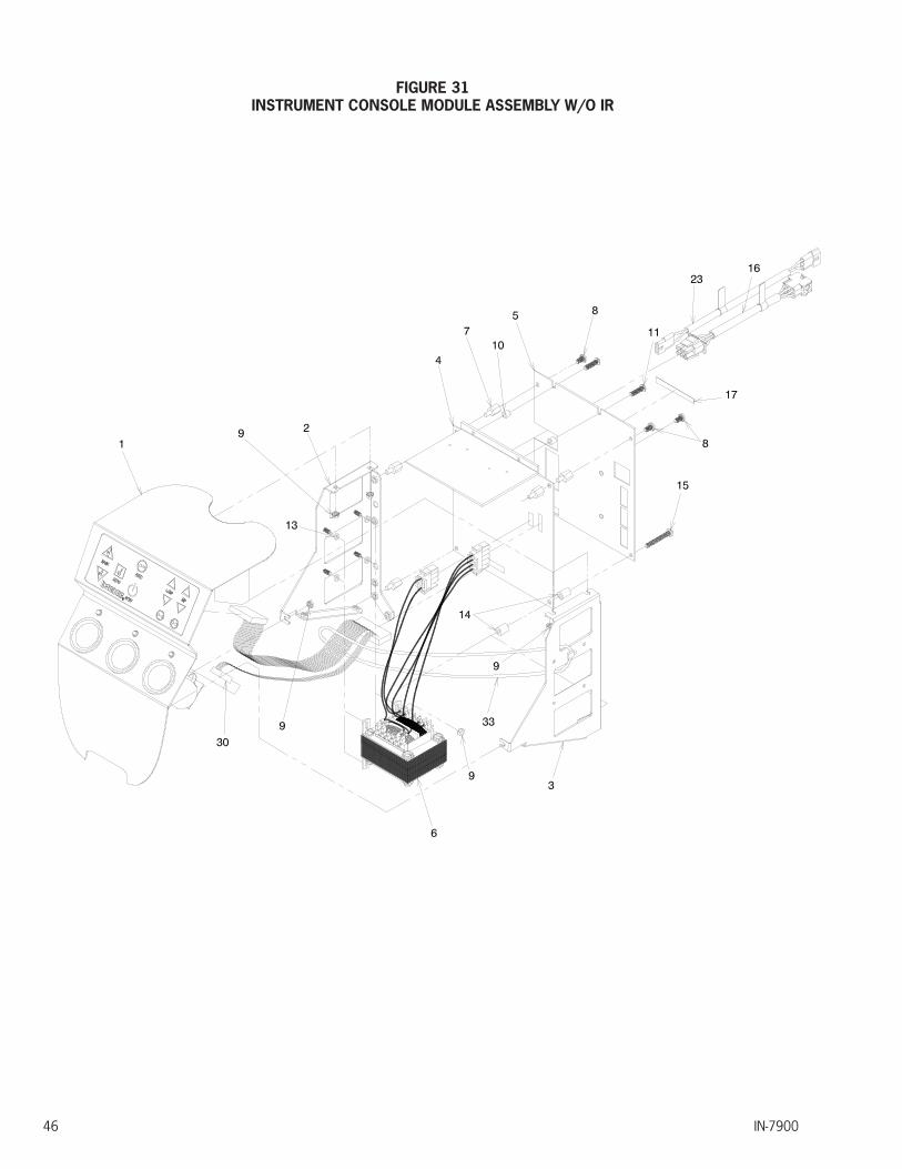
IN-790046
FIGURE 31INSTRUMENT CONSOLE MODULE ASSEMBLY W/O IR

IN-7900 47
ITEM PART NO. DESCRIPTION ITEM PART NO. DESCRIPTION
1 1966292 Face Plate Assembly-7900 W/O IR 18 1644299 Membrane Switch W/O IR
2 1971899 Module - Side Frame - LH 19 0733199 Retaining Ring
3 1971999 Module - Side Frame - RH 20 0706599 #6-32 Keps Nuts
4 1977199 Circuit Board Assembly - W/O IR 21 1622899 L.E.D. Light Assembly
5 1972599 Chassis Plate 22 2006499 Contact Stud-Short
6 1978992 Transformer Assembly 23 1663092 Lamp Cord Jumper
7 1734599 #10-32 x 7/16 M/F - Hex - Standoff 24 0505299 Battery Socket
8 1734799 #10-32 x 3/8 P.H.M.S. W/ Lockwasher 25 0489199 Contact Spring
9 0706699 #8-32 Keps Nut 26 1614999 Standoff, Hex Male/Female-Brass
10 1979399 Spacer 27 1550999 Circuit Board Assembly-Wells
11 1731999 #10-32 x .75 R.H.M.S. - Nylon 28 1658699 Pan H.M.S. #6-32 x 1/4 W/Lockwasher
12 1970999 Face Plate - Console 29 0705599 #10-32 Kep Nuts
13 0977799 Rubber Washer 30 1970399 Ribbon Cable Assembly
14 1979899 Spacer 31 1976899 Membrane Frame Assembly
15 1979999 #10-32 x 1.5 P.H.M.S 32 1976499 Face Plate - Mount Tab
16 2040292 B/P Jumper 33 0904499 Ty-Wrap
17 Labe-Serial Numberl 34
27
26
932
25
29
28
24
19
31 9
30
21
22
20
1218
To order complete Console Assembly use P/N.
1968592 7900 Console Module Assembly Without IR
*Please specify paint color when ordering.
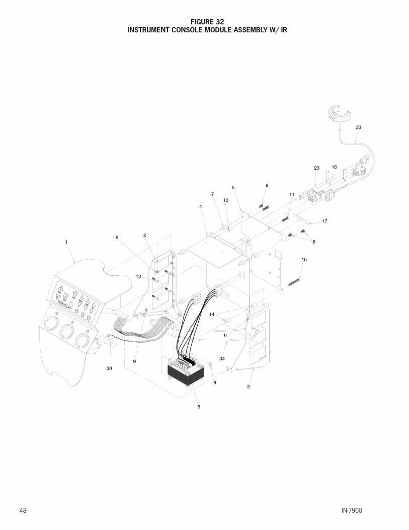
IN-790048
FIGURE 32INSTRUMENT CONSOLE MODULE ASSEMBLY W/ IR

IN-7900 49
27
26
932
25
29
28
24
19
31 9
30
21
22
20
1218
ITEM PART NO. DESCRIPTION ITEM PART NO. DESCRIPTION
1 1966392 Face Plate Assembly-7900 W/ IR 18 1644399 Membrane Switch W/ IR
2 1971899 Module - Side Frame - LH 19 0733199 Retaining Ring
3 1971999 Module - Side Frame - RH 20 0706599 #6-32 Kep Nuts
4 1977299 Circuit Board Assembly - W/ IR 21 1622899 L.E.D. Light Assembly
5 1972599 Chassis Plate 22 2006499 Contact Stud-Short
6 1978992 Transformer Assembly 23 1663092 Lamp Cord Jumper
7 1734599 #10-32 x 7/16 M/F - Hex - Standoff 24 0505299 Battery Socket
8 1734799 #10-32 x 3/8 P.H.M.S. W/ Lockwasher 25 0489199 Contact Spring
9 0706699 #8-32 Keps Nut 26 1614999 Standoff, Hex Male/Female-Brass
10 1979399 Spacer 27 1550999 Circuit Board Assemby-Wells
11 1731999 #10-32 x .75 R.H.M.S. - Nylon 28 1658699 Pan H.M.S. #6-32 x 1/4 W/Lockwasher
12 1970999 Face Plate - Console 29 0705599 #10-32 Kep Nuts
13 0977799 Rubber Washer 30 1970399 Ribbon Cable Assembly
14 1979899 Spacer 31 1976899 Membrane Frame Assembly
15 1979999 #10-32 x 1.5 P.H.M.S 32 1976499 Face Plate - Mount Tab
16 2040292 B/P Jumper 33 1734692 Transmitter - IR
17 Label - Serial Number 34 0904499 Ty-Wrap
To order complete Console Assembly use P/N.
1968692 7900 Console Module Assembly With IR
*Please specify paint color when ordering.

IN-790050
1
3
15
12
2
8
4
2
15
5
16
7
6
17
18
19
20
FIGURE 33BASE CAP MODULE ASSEMBLY - WITH IR
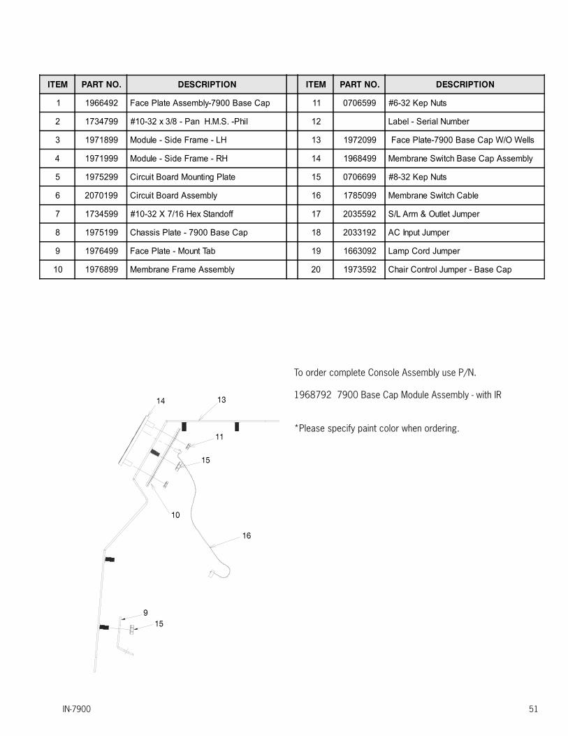
IN-7900 51
ITEM PART NO. DESCRIPTION ITEM PART NO. DESCRIPTION
1 1966492 Face Plate Assembly-7900 Base Cap 11 0706599 #6-32 Kep Nuts
2 1734799 #10-32 x 3/8 - Pan H.M.S. -Phil 12 Label - Serial Number
3 1971899 Module - Side Frame - LH 13 1972099 Face Plate-7900 Base Cap W/O Wells
4 1971999 Module - Side Frame - RH 14 1968499 Membrane Switch Base Cap Assembly
5 1975299 Circuit Board Mounting Plate 15 0706699 #8-32 Kep Nuts
6 2070199 Circuit Board Assembly 16 1785099 Membrane Switch Cable
7 1734599 #10-32 X 7/16 Hex Standoff 17 2035592 S/L Arm & Outlet Jumper
8 1975199 Chassis Plate - 7900 Base Cap 18 2033192 AC Input Jumper
9 1976499 Face Plate - Mount Tab 19 1663092 Lamp Cord Jumper
10 1976899 Membrane Frame Assembly 20 1973592 Chair Control Jumper - Base Cap
To order complete Console Assembly use P/N.
1968792 7900 Base Cap Module Assembly - with IR
*Please specify paint color when ordering.

IN-790052
FIGURE 34WIRE DIAGRAM - CONSOLE (WITH AND WITHOUT IR)

IN-7900 53
IN-790054
FIGURE 35WIRE DIAGRAM - BASE CAP - WITH IR
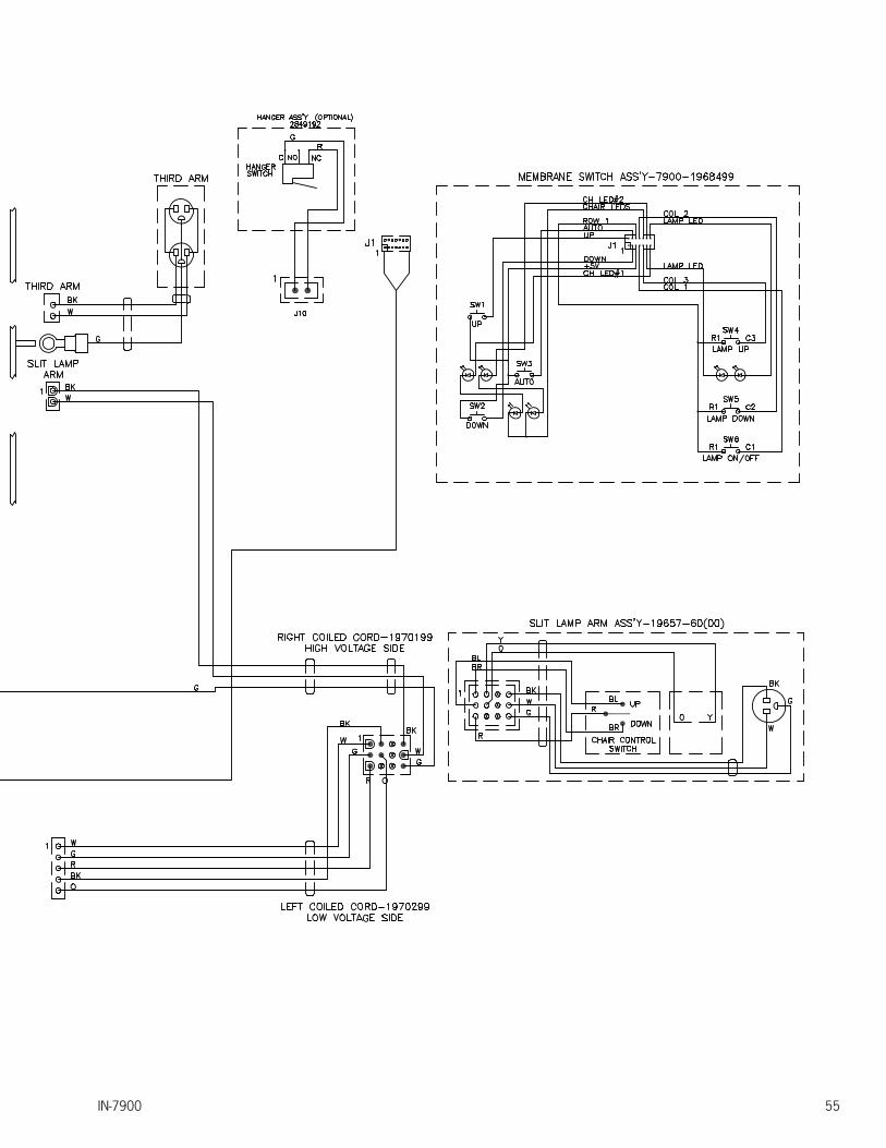
IN-7900 55

IN-790056
(NOTES)

IN-7900 57
(NOTES)

IN-790058
(NOTES)
IN-7900 59
LIMITED WARRANTY
The Reliance® product must be used only for the purposes and in the manner described in the literature distributed with the product. The products are warranted against defective materials and workmanship for a period of one (1) year from date of installation. Products or parts thereof will be repaired or replaced as required at Reliance® Medical Products, Inc. Such repair or replacement shall be the sole remedy under this warranty. This warranty extends only to the original purchaser from an authorized Reliance® dealer and is subject to the following conditions:
1. The warranty card must be completed and returned to Reliance® Medical Products, Inc. within two (2) weeks from the date of installation.
2. Installation and servicing of the products must be performed by trained Reliance® equipment dealer service personnel in accordance with the appropriate instructions manual for the products. Warranty will be voided if installation is performed by a non-authorized individual
3. The products have not sustained breakage or other types of damage due to accident or misuse.
4. This warranty will not apply to Reliance® products which have had the serial number removed, altered or effaced.
EXCEPT FOR THE EXPRESS WARRANTY SET FORTH ABOVE, RELIANCE® DOES NOT GRANT ANY WARRANTIES, EITHER EXPRESS OR IMPLIED, INCLUDING IMPLIED WARRANTIES OF MERCHANTABILTY OR FITNESS FOR A PARTICULAR USE.
Reliance® Medical Products neither assumes nor authorizes any person to assume for it, any other liability in connection with the sale and use of its products.
REMEDIES ARE LIMITED EXCLUSIVELY TO REPAIR OR REPLACEMENT OF PARTS. RELIANCE® MEDICAL PRODUCTS, INC. EXPRESSLY DISCLAIMS LIABILITY FOR INCIDENTAL OR CONSEQUENTIAL DAMAGE RESULTING FROM THE USE OF THE EQUIPMENT.
Claims covered by this warranty will be honored when presented within one (1) month from discovery of a defect.

Reliance Medical Products, Inc.3535 Kings Mills RoadMason, Ohio 45040-2303 USA1-800-735-0357 (Customer Service)1-800-735-0358 (Technical Service)(513) 398-3937Http://www.reliance-medical.com
P/N 19700 REV J
© Copyright 2009 Printed in U.S.A.
Revised 1-2018-9011
MADE IN AMERICA
Related Documents


![[TNO stereo test] HAAG-STREIT UK 40crn 60 ...jfcsp.co.jp/catalog/haag/tno_stereoTest.pdf[TNO stereo test] HAAG-STREIT UK 40crn 60 13BIX00049CC0001 innovation for life PlatelV test](https://static.cupdf.com/doc/110x72/5f2fb83aa17d3c03f71ef559/tno-stereo-test-haag-streit-uk-40crn-60-jfcspcojpcataloghaagtno-tno.jpg)