CC1N7761en 21.08.2018 Building Technologies 7 761 Control Units LEC1... Control unit for double- or multiflame supervision of oil, gas or forced draft oil / gas burners of any fuel throughput, suited for continuous or intermittent operation. The LEC1... and this Data Sheet are intended for use by OEMs which integrate the control units in their products! Use The LEC1... is designed for the fully automatic startup and supervision of forced draft oil or gas burners where flame supervision should or must be carried out by separate flame safeguards, e.g. with: · Double supervision of the main flame or pilot and main flame by 2 identical or different detectors · Supervision of forced draft oil / gas burners with different types of detectors, depending on the selected operating mode · Multiflame supervision, that is, central and simultaneous control of the startup and supervision sequence of several burners the flames of which must be individually supervised by 1 or 2 flame safeguards each Supplementary Data Sheets · LAE10 Data Sheet N7781 · LFE10 Data Sheet N7781 · LFE50 Data Sheet N7783 C Note! Do not use for new designs.

Welcome message from author
This document is posted to help you gain knowledge. Please leave a comment to let me know what you think about it! Share it to your friends and learn new things together.
Transcript
CC1N7761en21.08.2018
Building Technologies
7761
Control Units LEC1...
Control unit for double- or multiflame supervision of oil, gas or forced draft oil /gas burners of any fuel throughput, suited for continuous or intermittentoperation.
The LEC1... and this Data Sheet are intended for use by OEMs which integrate thecontrol units in their products!
UseThe LEC1... is designed for the fully automatic startup and supervision of forced draftoil or gas burners where flame supervision should or must be carried out by separateflame safeguards, e.g. with:
· Double supervision of the main flame or pilot and main flame by 2 identical ordifferent detectors
· Supervision of forced draft oil / gas burners with different types of detectors,depending on the selected operating mode
· Multiflame supervision, that is, central and simultaneous control of the startup andsupervision sequence of several burners the flames of which must be individuallysupervised by 1 or 2 flame safeguards each
Supplementary Data Sheets· LAE10 Data Sheet N7781· LFE10 Data Sheet N7781· LFE50 Data Sheet N7783
C Note!Do not use for new designs.
2/19
Building Technologies CC1N7761en21.08.2018
Use (cont´d)
LAE10 For the supervision of oil burners with an active photocell detector RAR…in intermittent operation
LFE10 For the supervision with an ionization probe (gas burners) or with UVdetectors QRA… (gas, oil or dual-fuel burners, with or without ignitionspark proving) in intermittent operation
LFE50 For the supervision with UV detectors QRA50… / QRA51…(gas, oil ordual-fuel burners) in intermittent or continuous operation
All units comply with the relevant European standards for oil, gas and forced draftburners of any fuel throughput.
The LEC1... can control the following burner plant components:Fan motor, flue gas fan, air damper, ignition transformer, 1 to 3 fuel valves, loadcontroller, and an external fault signaling device.
A load controller with 3-position output can be connected.
Design, control sequence and adjustment facilities of the control unit make it suitablefor use on combustion plants of any size and type, be it in connection with expandingflame or interrupted pilot burners, continuously operating burners or any other specialburners.
· Prepurge time adjustable between 8 and 63 seconds· Operation with or without postpurging· Fully automatic control of air damper possible, irrespective of the actuator run time· Possibility of air pressure check in connection with functional control of the air
pressure switch prior to startup· Choice of ignition: Direct ignition with pilot burner, with or without ignition spark
proving· Preignition time can be set to «Long» (during the prepurge time) or «Short» (3
seconds, e.g. for forced draft gas burners)· 1st and 2nd safety time adjustable between 0 and 9 seconds· Automatic extraneous light test during burner off periods and during the purging
times (with lockout in the event of faulty flame signals)· Semi-automatic burner startup and operation possible· Built-in lockout warning lamp· Electrical remote reset facility· Cover with 2 additional sealing screws to provide protection against tampering
(refer to «Dimensions»)· Continuous display of the program sequence in the cover’s viewing window· In the event of a fault, the program indicator shows the operating phase during
which the fault occurred· Motor of the programming mechanism can be switched off to simplify burner
adjustments· Camshaft can be rotated manually
The following types offlame safeguards areavailable:
Special features
3/19
Building Technologies CC1N7761en21.08.2018
Warning notesTo avoid injury to persons, damage to property or the environment, the followingwarning notes should be observed!
Only authorized staff may open, interfere with or modify the unit!
· All activities (mounting, installation and service work, etc.) must be performed byqualified staff
· Before performing any wiring changes in the connection area of the LEC1…,completely isolate the unit from the mains supply (all-polar disconnection)
· Ensure protection against electrical shock hazard by providing adequate protectionfor the unit’s terminals
· Each time work has been carried out (mounting, installation, service work, etc.),check to ensure that wiring is in an orderly state and make the safety checks asdescribed in «Commissioning notes»
· Press lockout reset button only manually (applying a force of no more than 10 N),without using any tools or pointed objects
· Fall or shock can adversely affect the safety functions. Such units must not be putinto operation, even if they do not exhibit any damage
· Do not press the lockout reset button on the unit or the remote lockout reset buttonfor more than 10 seconds since this damages the lockout relay in the unit
Mounting notes· Ensure that the relevant national safety regulations are complied with· Locate ignition electrode and ionization probe such that the ignition spark cannot
arc over to the ionization probe (risk of electrical overloads)
Installation notes· Always run the high-voltage ignition cables separately while observing the greatest
possible distances to the unit and to other cables· 4 extra terminals for the earth conductor, 4 extra terminals for the neutral
conductor, and 4 auxiliary terminals· In the event of loss of flame during operation, the control unit will initiate lockout· Do not mix up live and neutral conductors· Install switches, fuses, earthing, etc., in compliance with local regulations· Observe the maximum permissible current load of the connecting terminals
Electrical connection of the flame detectors
It is important to achieve practically disturbance- and loss-free signal transmission:· Never run the detector cable together with other cables
– Line capacitance reduces the magnitude of the flame signal– Use a separate cable
· Observe the maximum permissible lengths of the detector cables (refer to«Technical data» at current flame safeguards
· The ionization probe is not protected against electric shock hazard· Locate the ignition electrode and ionization probe such that the ignition spark
cannot arc over to the ionization probe (risk of electrical overloads) and an overrideof ionization supervision via ignition spark must be avoided
· Insulation resistance– Must be a minimum of 50 MW between ionization probe and ground– Soiled detector holders reduce the insulation resistance, thus supporting creepage currents
· Earth the burner in compliance with the relevant regulations; earthing the boileralone does not suffice
4/19
Building Technologies CC1N7761en21.08.2018
Commissioning notes
· Continuous display of the program sequence in the viewing window:It is also possible to program the unit by means of a changeover link (UL3) in a waythat the programming mechanism does not stop in case of lockout, but that it runsto the end of the program. The only component that receives power during thatperiod of time is the fan for postpurging (connected to terminal 17)
· The motor of the programming mechanism can be switched off (simplifies burneradjustments)
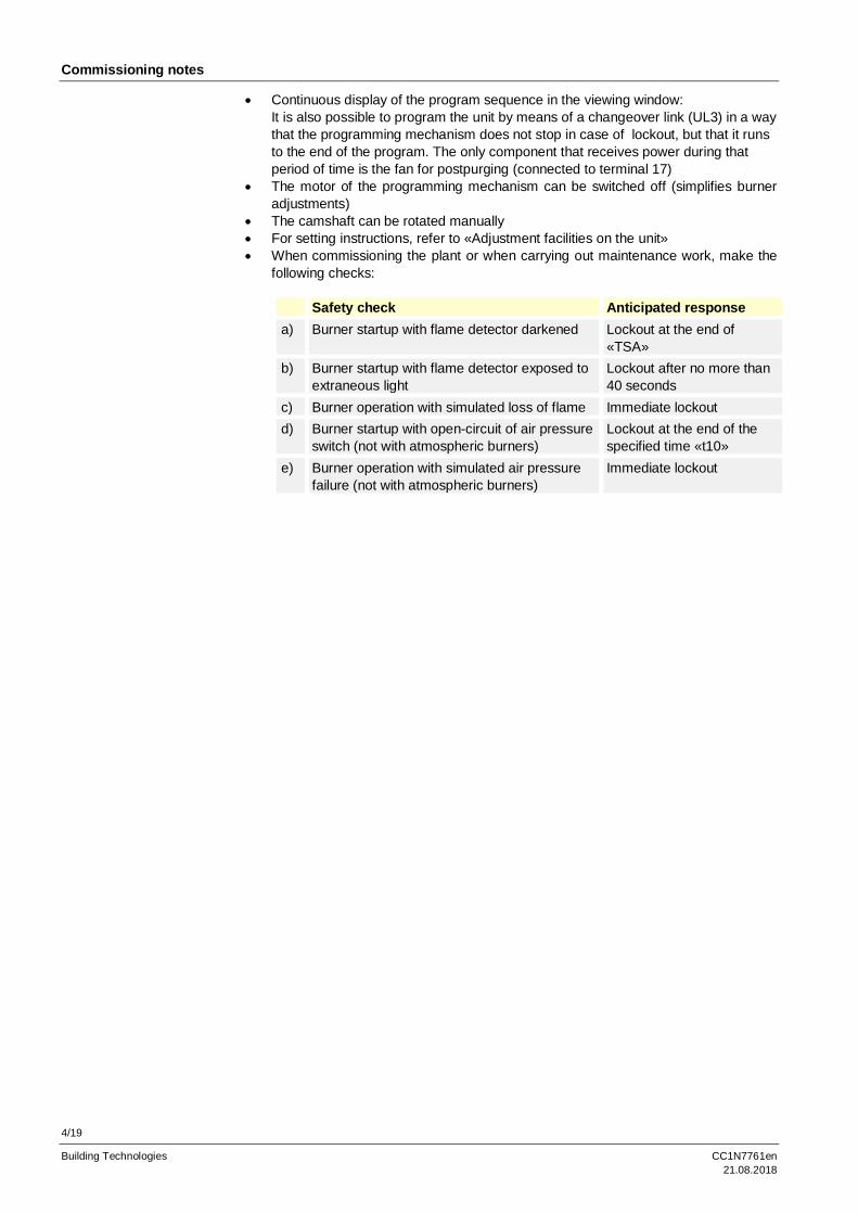
· The camshaft can be rotated manually· For setting instructions, refer to «Adjustment facilities on the unit»· When commissioning the plant or when carrying out maintenance work, make the
following checks:
Safety check Anticipated responsea) Burner startup with flame detector darkened Lockout at the end of
«TSA»b) Burner startup with flame detector exposed to
extraneous lightLockout after no more than40 seconds
c) Burner operation with simulated loss of flame Immediate lockoutd) Burner startup with open-circuit of air pressure
switch (not with atmospheric burners)Lockout at the end of thespecified time «t10»
e) Burner operation with simulated air pressurefailure (not with atmospheric burners)
Immediate lockout
5/19
Building Technologies CC1N7761en21.08.2018
Standards and certificates
Applied directives:· Low-voltage directive 2014/35/EU· Electromagnetic compatibility EMC (immunity) *) 2014/30/EU
*) The compliance with EMC emission requirements must be checked after the burner control is
installed in equipment
C Note!These devices may only be used as replacements within the EU and EFTA countries.
Compliance with the regulations of the earlier, now withdrawn directives is verified bythe adherence to the following standards:· Automatic burner control systems for oil burners DIN EN 230:2005· Automatic burner control systems for burners and
appliances burning gaseous or liquid fuelsDIN EN 298:2004
· Automatic electrical controls for household and similarusePart 2-5:Particular requirements for automatic electrical burnercontrol systems
DIN EN 60730-2-5:2005
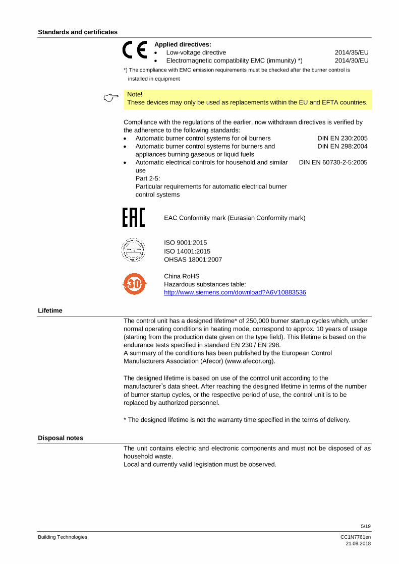
EAC Conformity mark (Eurasian Conformity mark)
ISO 9001:2015ISO 14001:2015OHSAS 18001:2007
China RoHSHazardous substances table:http://www.siemens.com/download?A6V10883536
LifetimeThe control unit has a designed lifetime* of 250,000 burner startup cycles which, undernormal operating conditions in heating mode, correspond to approx. 10 years of usage(starting from the production date given on the type field). This lifetime is based on theendurance tests specified in standard EN 230 / EN 298.A summary of the conditions has been published by the European ControlManufacturers Association (Afecor) (www.afecor.org).
The designed lifetime is based on use of the control unit according to themanufacturer’s data sheet. After reaching the designed lifetime in terms of the numberof burner startup cycles, or the respective period of use, the control unit is to bereplaced by authorized personnel.
* The designed lifetime is not the warranty time specified in the terms of delivery.
Disposal notesThe unit contains electric and electronic components and must not be disposed of ashousehold waste.Local and currently valid legislation must be observed.
6/19
Building Technologies CC1N7761en21.08.2018
Mechanical design
The LEC1... as well as the flame safeguards LAE10 and LFE10 are of plug-in designand suitable for mounting in any position on the burner, on control desks or in controlpanels.The spacious terminal bases and housings are made of impact-proof and heat-resistantplastic.The programming mechanism of the unit (driven by a synchronous motor), its auxiliaryrelays and all other switching, control and adjusting elements are mounted on robustprinted circuit boards.
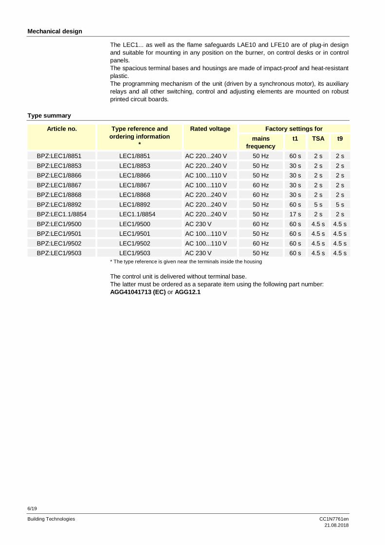
Type summary
Article no. Type reference andordering information
*
Rated voltage Factory settings formains
frequencyt1 TSA t9
BPZ:LEC1/8851 LEC1/8851 AC 220...240 V 50 Hz 60 s 2 s 2 sBPZ:LEC1/8853 LEC1/8853 AC 220...240 V 50 Hz 30 s 2 s 2 sBPZ:LEC1/8866 LEC1/8866 AC 100...110 V 50 Hz 30 s 2 s 2 sBPZ:LEC1/8867 LEC1/8867 AC 100...110 V 60 Hz 30 s 2 s 2 sBPZ:LEC1/8868 LEC1/8868 AC 220...240 V 60 Hz 30 s 2 s 2 sBPZ:LEC1/8892 LEC1/8892 AC 220...240 V 50 Hz 60 s 5 s 5 sBPZ:LEC1.1/8854 LEC1.1/8854 AC 220...240 V 50 Hz 17 s 2 s 2 sBPZ:LEC1/9500 LEC1/9500 AC 230 V 60 Hz 60 s 4.5 s 4.5 sBPZ:LEC1/9501 LEC1/9501 AC 100...110 V 50 Hz 60 s 4.5 s 4.5 sBPZ:LEC1/9502 LEC1/9502 AC 100...110 V 60 Hz 60 s 4.5 s 4.5 sBPZ:LEC1/9503 LEC1/9503 AC 230 V 50 Hz 60 s 4.5 s 4.5 s
* The type reference is given near the terminals inside the housing
The control unit is delivered without terminal base.The latter must be ordered as a separate item using the following part number:AGG41041713 (EC) or AGG12.1
7/19
Building Technologies CC1N7761en21.08.2018
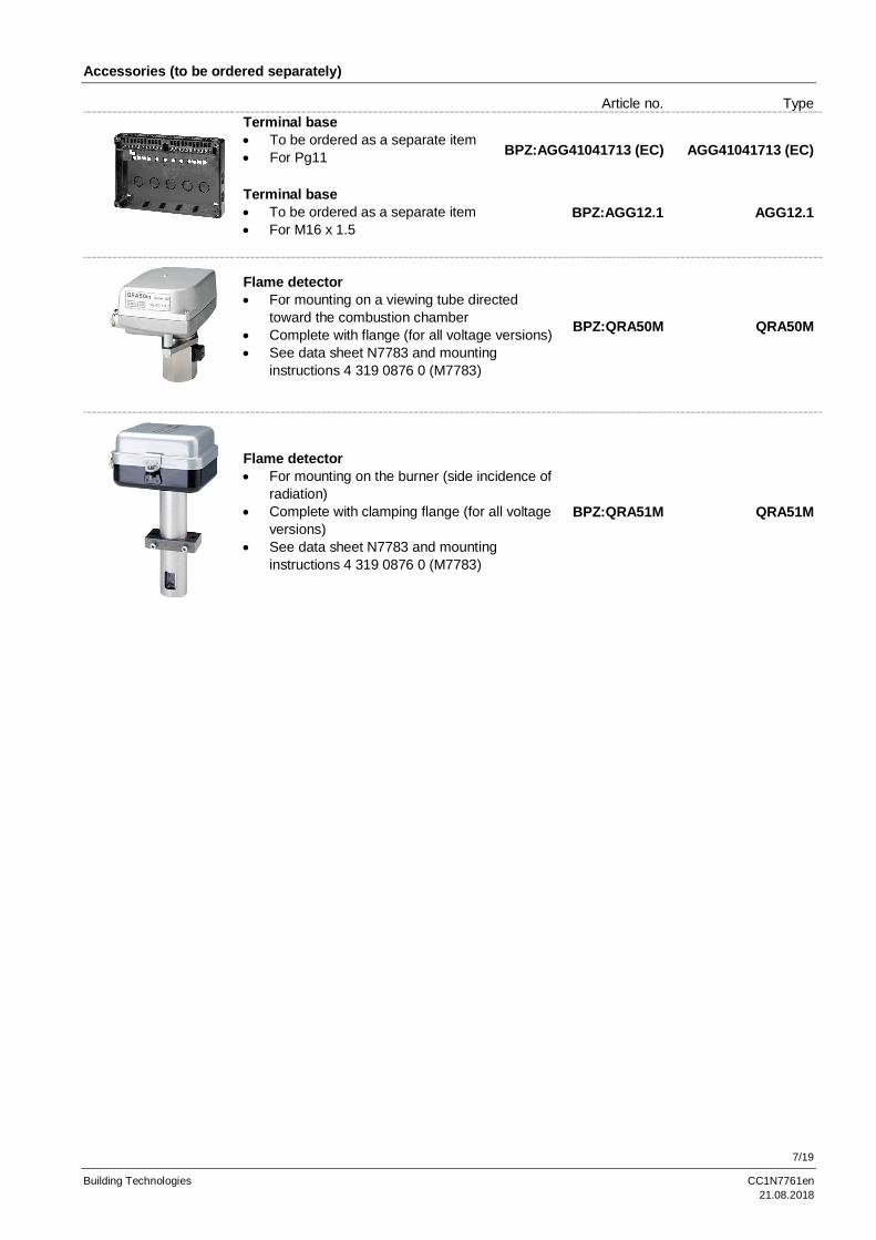
Accessories (to be ordered separately)
Article no. TypeTerminal base· To be ordered as a separate item· For Pg11 BPZ:AGG41041713 (EC) AGG41041713 (EC)
Terminal base· To be ordered as a separate item· For M16 x 1.5
BPZ:AGG12.1 AGG12.1
Flame detector· For mounting on a viewing tube directed
toward the combustion chamber· Complete with flange (for all voltage versions)· See data sheet N7783 and mounting
instructions 4 319 0876 0 (M7783)
BPZ:QRA50M QRA50M
Flame detector· For mounting on the burner (side incidence of
radiation)· Complete with clamping flange (for all voltage
versions)· See data sheet N7783 and mounting
instructions 4 319 0876 0 (M7783)
BPZ:QRA51M QRA51M
8/19
Building Technologies CC1N7761en21.08.2018
Technical data
Mains voltage AC 220 V -15 %...AC 240 V +10 %AC 100 V -15 %...AC 110 V +10 %
Mains frequency 50...60 Hz ±6 %Unit fuse, built-in T6.3H250V to DIN EN 60 127External fuse Max. 10 A (slow)Power consumption· During startup· During operation
8 VA5 VA
Permissible load on the control outputs· Per terminal· Total
Max. 4 A to VDE 0660 AC3Max. 5 A to VDE 0660 AC3
Degree of protection IP 40 (to be ensured through mounting)Mounting position OptionalCable glands · Pg11 or
· BSP ¾“ or· metric M16 x 1.5
Weight approx. 2 kg
Storage DIN EN 60721-3-1Climatic conditions Class 1K3Mechanical conditions Class 1M2Temperature range -20...+60 °CHumidity < 95 % r.h.Transport DIN EN 60 721-3-2Climatic conditions Class 2K2Mechanical conditions Class 2M2Temperature -50...+60 °CHumidity < 95 % r.h.Operation DIN EN 60 721-3-3Climatic conditions Class 3K5Mechanical conditions Class 3M2Temperature -20...+60 °CHumidity < 95 % r.h.Installation altitude Max. 2,000 m above sea level
Warning!Condensation, formation of ice and ingress of water are not permitted!If this is not observed, there is a risk of loss of safety functions and a risk ofelectric shock.
· With LAE10· With LFE10· With LFE50
General unit data
Environmentalconditions
Flame supervision
9/19
Building Technologies CC1N7761en21.08.2018
FunctionThe following description of the unit’s function refers to the startup and supervision of asingle burner. With multiflame supervision, all burners connected to the control unit areput into operation and supervised simultaneously in the same manner. A fault causinglockout of one of the burners therefore results in the shutdown of all burners.Prerequisite for the immediate restart of the non-faulty burners is the bridging of theflame safeguard of the faulty burner by means of an operating switch. This switch mustsimultaneously cut all control lines to the ignition transformer and the fuel valves. Forconnection examples, refer to the Data Sheet on the LAE10 / LFE10.
The burner starts only if:- The unit’s switching sequence is in the start position- The control unit is not in the lockout position, e.g. due to a faulty UV tube- The contacts of all the control and safety devices in the control loop between
terminal 8 and 9 are closed- The air pressure switch does not indicate any air pressure – if connected in the test
circuit
Faults in the flame safeguard or in the control unit prevent startup or lead to a lockoutduring startup.
F Note!If the air damper is not controlled by the control unit, terminals 20, 21 and 22 must beinterconnected.
... on startupFirst, the fan motor is switched on via terminal 3 and the actuator is controlled viaterminal 22. When the air damper reaches its fully open position, the programmingmechanism of the unit starts to run – the prepurge time commences. The minimum airpressure set on the air pressure switch must then be reached within 10 seconds (orwithin 7 seconds in operation with postpurging) and must be maintained until controlledshutdown occurs. Otherwise, lockout will take place. A flame signal during the prepurgetime also leads to lockout. On completion of the set prepurge time, the air damper isgiven the control command to return to the minimum air position. During the airdamper’s closing time, the programming mechanism does not move.
As soon as the signal contact for the minimum throttling position is operated by theactuator, the programming mechanism starts again and now controls the programsequence which can no longer be influenced from outside.· Preignition (provided the ignition equipment was not already switched on during the
prepurge time)· Release of the 1st fuel valve connected to terminal 5 (the fuel valve of a pilot
burner which must be closed on completion of the 2nd safety time must, however,be connected to terminal 10)
· The set safety time elapses. If no flame is established during that period of time,lockout will be initiated (control unit always locks itself)
· On completion of an interval of 11 seconds after the release of the 1st valve, the2nd fuel valve will be released
· The pilot burner – if present – is switched off (connected to terminal 10)· The load controller is switched on after a further interval of 12 seconds. Now the
burner has reached its operating position. From now on, the load controller controlsthe burner’s output by either increasing or decreasing the fuel throughput and theair volume depending on heat demand (fuel / air ratio control). This can beaccomplished in stages, i.e. by means of thermostats or continuously (modulating)by a modulating controller
Loss of flame during operation always leads to lockout of the burner.
Prerequisites for burnerstartup
Startup sequence...
10/19
Building Technologies CC1N7761en21.08.2018
Function (cont´d)In principle, the program sequence is the same as with burner startup without ignitionspark proving.
Exceptions:· If the UV flame detector does not receive any input signal during the short
preignition time (UL2 on «Short preignition»), lockout occurs before any gas isreleased, i.e. safety time TSA = 0 seconds
· With ignition spark proving, the safety time for the pilot burner can only be adjustedbetween 0...6 seconds (in the time diagram of the programming mechanism: TSA´)
... after a controlled shutdownControlled shutdown occurs as soon as one of the control or supervision devices in thecontrol loop between terminal 8 and 9 opens its contact. In that case, the fuel valveswill immediately be shut. The programming mechanism starts again and now programspostpurging, if required. On completion of the postpurge time, the programmingmechanism has again reached its start position where it remains until the next switchon command is received. The flame supervision restarts again during the postpurgetime. Therefore, any flame signal during that period of time will lead to lockout.
... after resetting the LEC1...After pressing the built-in or the external lockout reset button, the programmingmechanism will return to its start position. The only burner plant component that isoperated during that period time is a fan motor connected to terminal 17. As the controlthermostat or pressurestat normally continues to call for heat, the programmingmechanism will initiate a restart after reaching the start position.
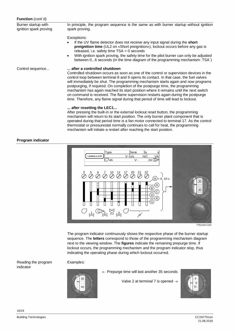
Program indicator
LANDIS & GYR
Type Serie ts sV~ c/s Hz VA
4A V~ 2A
3 5 6 7 10 11 17 20 21 22
1 2 3
t1
AB
CD
EG
= 8...63 s
(1)
7761z01/1102
40
30
The program indicator continuously shows the respective phase of the burner startupsequence. The letters correspond to those of the programming mechanism diagramnext to the viewing window. The figures indicate the remaining prepurge time. Iflockout occurs, the programming mechanism and the program indicator stop, thusindicating the operating phase during which lockout occurred.
Examples:
40
30
¬ Prepurge time will last another 35 seconds
Valve 2 at terminal 7 is opened ®D
FE
Burner startup withignition spark proving
Control sequence...
Reading the programindicator
11/19
Building Technologies CC1N7761en21.08.2018
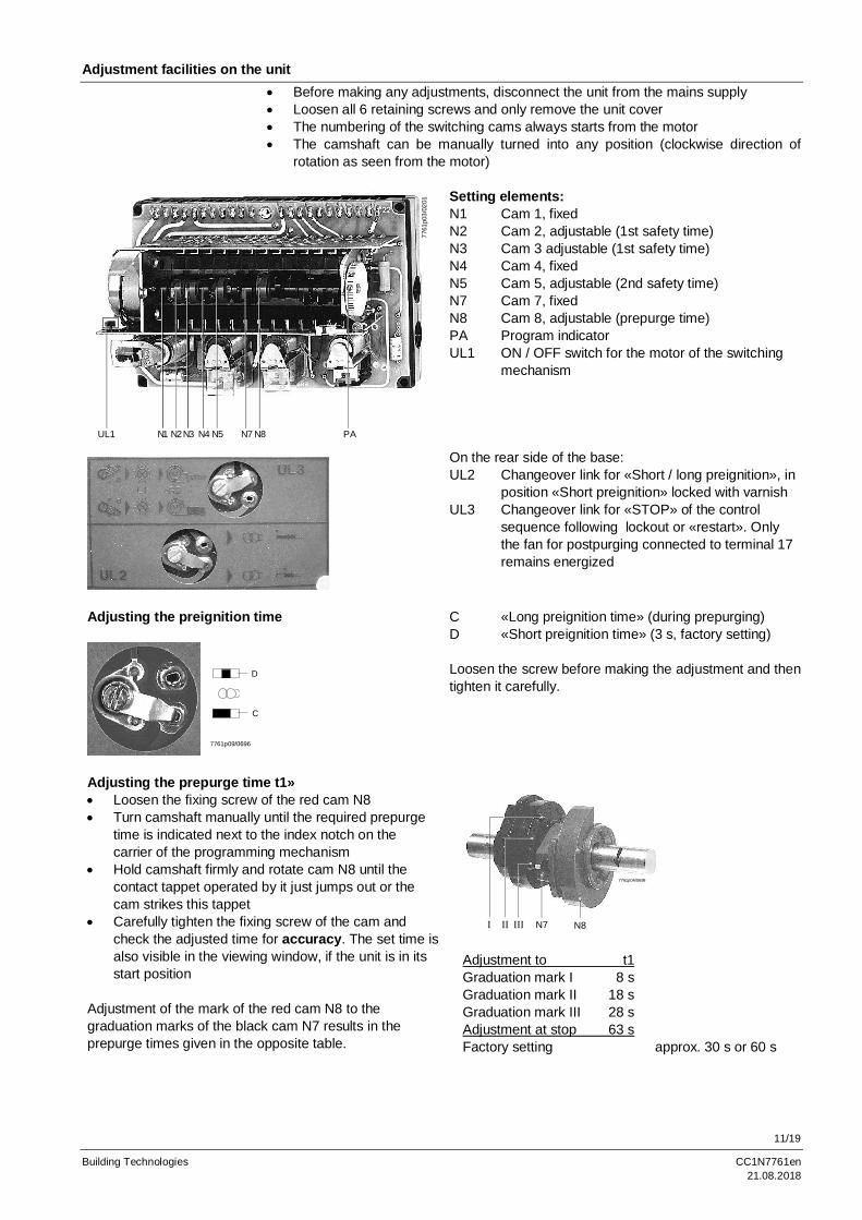
Adjustment facilities on the unit· Before making any adjustments, disconnect the unit from the mains supply· Loosen all 6 retaining screws and only remove the unit cover· The numbering of the switching cams always starts from the motor· The camshaft can be manually turned into any position (clockwise direction of
rotation as seen from the motor)
UL1 N1 N2N3 N4 N5 N7 N8 PA77
61p0
3/02
01 Setting elements:N1 Cam 1, fixedN2 Cam 2, adjustable (1st safety time)N3 Cam 3 adjustable (1st safety time)N4 Cam 4, fixedN5 Cam 5, adjustable (2nd safety time)N7 Cam 7, fixedN8 Cam 8, adjustable (prepurge time)PA Program indicatorUL1 ON / OFF switch for the motor of the switching
mechanism
On the rear side of the base:UL2 Changeover link for «Short / long preignition», in
position «Short preignition» locked with varnishUL3 Changeover link for «STOP» of the control
sequence following lockout or «restart». Onlythe fan for postpurging connected to terminal 17remains energized
Adjusting the preignition time
D
C
7761p09/0696
C «Long preignition time» (during prepurging)D «Short preignition time» (3 s, factory setting)
Loosen the screw before making the adjustment and thentighten it carefully.
Adjusting the prepurge time t1»· Loosen the fixing screw of the red cam N8· Turn camshaft manually until the required prepurge
time is indicated next to the index notch on thecarrier of the programming mechanism
· Hold camshaft firmly and rotate cam N8 until thecontact tappet operated by it just jumps out or thecam strikes this tappet
· Carefully tighten the fixing screw of the cam andcheck the adjusted time for accuracy. The set time isalso visible in the viewing window, if the unit is in itsstart position
Adjustment of the mark of the red cam N8 to thegraduation marks of the black cam N7 results in theprepurge times given in the opposite table.
I II III N7 N8
7761p04/0698
Adjustment to t1Graduation mark I 8 sGraduation mark II 18 sGraduation mark III 28 sAdjustment at stop 63 sFactory setting approx. 30 s or 60 s
12/19
Building Technologies CC1N7761en21.08.2018
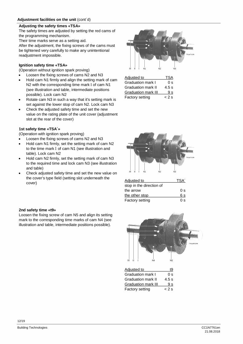
Adjustment facilities on the unit (cont´d)Adjusting the safety times «TSA»The safety times are adjusted by setting the red cams ofthe programming mechanism.Their time marks serve as a setting aid.After the adjustment, the fixing screws of the cams mustbe tightened very carefully to make any unintentionalreadjustment impossible.
Ignition safety time «TSA»(Operation without ignition spark proving)· Loosen the fixing screws of cams N2 and N3· Hold cam N1 firmly and align the setting mark of cam
N2 with the corresponding time mark I of cam N1(see illustration and table, intermediate positionspossible). Lock cam N2
· Rotate cam N3 in such a way that it's setting mark isset against the lower stop of cam N2. Lock cam N3
· Check the adjusted safety time and set the newvalue on the rating plate of the unit cover (adjustmentslot at the rear of the cover)
III II I N1 N2 N3
7761p07/1296
Adjusted to TSAGraduation mark I 0 sGraduation mark II 4.5 sGraduation mark III 9 sFactory setting < 2 s
1st safety time «TSA´»(Operation with ignition spark proving)· Loosen the fixing screws of cams N2 and N3· Hold cam N1 firmly, set the setting mark of cam N2
to the time mark I of cam N1 (see illustration andtable). Lock cam N2
· Hold cam N2 firmly, set the setting mark of cam N3to the required time and lock cam N3 (see illustrationand table)
· Check adjusted safety time and set the new value onthe cover’s type field (setting slot underneath thecover)
III II I N1 N2 N3
7761p07/1296
Adjusted to TSA´stop in the direction ofthe arrow 0 sthe other stop 6 sFactory setting 0 s
2nd safety time «t9»Loosen the fixing screw of cam N5 and align its settingmark to the corresponding time marks of cam N4 (seeillustration and table, intermediate positions possible).
N4 N5IIIIII
7761p08/1296
Adjusted to t9Graduation mark I 0 sGraduation mark II 4.5 sGraduation mark III 9 sFactory setting < 2 s
13/19
Building Technologies CC1N7761en21.08.2018
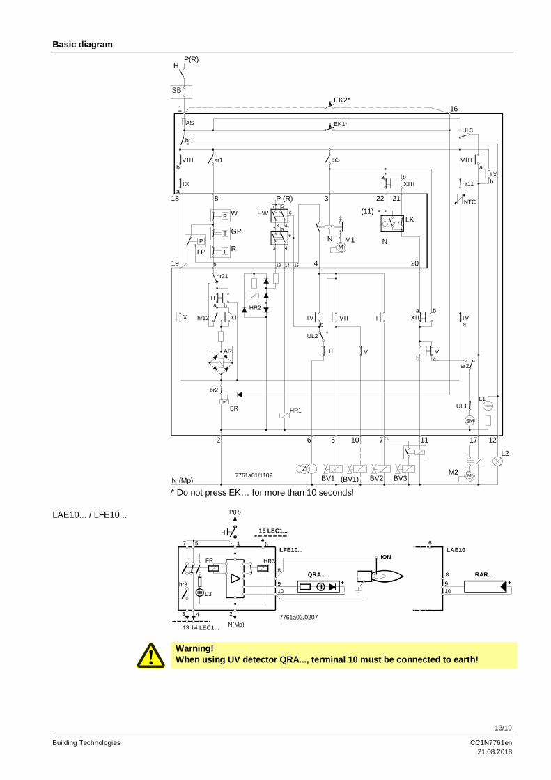
Basic diagramP(R)
H
1EK2*
16
N (Mp)
2
Z
6 5
BV1 (BV1) BV2 BV3M2 M~
L2
10 7 11 17 12
18
19LPP
8
P
T
T
9
R
W
GP
P (R)7
3
56
47
65
43
13 14 15 4
FW
NM~
M1
3
(11)
22 21
~
N
LK
20
y z
AS
br1
VI I Ib
I Xa
ar1
EK1*
ar3
a bXI I I
UL3
aVI I I
hr11I Xb
NTC
X
hr21
aI I
b
XIhr12
AR
br2
BR
HR2
IVb
UL2
I I I
HR1
VI I
V
Ia b
b a
XI I
VI
IVa
ar2
UL1
SM
L1
7761a01/1102
SB
* Do not press EK… for more than 10 seconds!
P(R)
H
10
13
3
7
hr3
24
N(Mp)14 LEC1...
615
HR3
9
FR
L3
8
7761a02/0207
LFE10...
15 LEC1...
+QRA...
ION
10
6
98
LAE10
+RAR...
Warning!When using UV detector QRA..., terminal 10 must be connected to earth!
LAE10... / LFE10...
14/19
Building Technologies CC1N7761en21.08.2018
Sequence diagram of programming mechanism
Maximum permissible afterburn time is 7 seconds - from the beginning of postpurge time «t6».
t3
t7
t1 0
t 1
t11t8
T
t12t6
TSA
t4 t9
t3 ´ t 5
3
63
66
70
93
9067
81
ab
ab
ab
ab
ab
ab
ab
I
II
III
IV
V
VI
VII
VIII
IX
X
XI
XII
XIII
7761d01/0201
10
TSA´
79
Legend AS Unit fuse LK Actuator with limit or auxiliary switchesAR Load relay with contacts «ar...» (refer so «Connection examples»)BR Lockout relay with contacts «br...» a = actuator travels to the OPEN positionBV... Fuel valve (maximum air volume)(BV...) Fuel valve for a pilot burner that is switched off on z = actuator travels to the CLOSED position
completion of the 2nd safety time (minimum air volume)c... Fan contactor with contacts «c...» LP Air pressure switchd... Auxiliary relay with contacts «d...» M... Fan motor, fane... Thermal cutout NTC Resistor with negative temperature coefficientEK1 Lockout reset button on LEC1... OV... Oil valveEK2 Remote lockout reset button Q Temperature or pressure sensorION Ionization probe QRA... UV detectorFR Flame relay with contacts R... Control thermostat or pressurestatFW Contacts of flame safeguards LAE10..., LFE10... RAR... Selenium photocell detector
or LFE50... RV Control valveGP Gas pressure switch SB Safety limiterGV... Gas valve SM Synchronous motor of programming mechanismH Main switch SQ... Type reference of air damper actuatorHR1 Auxiliary relay with contacts «hr11 / hr12» UL1 Operating switch for motor of programming mechanismHR2 Auxiliary relay with contact «hr21» – can only be accessed after removal of housing coverHR3 Auxiliary relay for flame detector or flame simulation UL2 Changeover link for «Short / long preignition time»
Test UL3 Changeover link for «STOP» or «Run» of theL1 Lockout warning lamp, built-in programming mechanism after lockoutL2 Lockout warning lamp, external W Limit thermostat or pressure switchL3 Signal lamp for flame indication Z Ignition transformer
Switching T 120 s Run time of programming mechanismtimes TSA 0...9 s Ignition safety time (setting = 0 s in the case Ignition safety time of ignition spark proving)
TSA´ 0...6 s First safety time for the pilot burner in the case of startup with ignition spark provingt1 8...63 s Adjustable prepurge timet3 t11 + t1 + t12 + 7 s Long preignition time (during the entire prepurge)t3´ 3 s Short preignition timet4 11 s Interval between release of the 1st and 2nd fuel valvet5 12 s Interval between release of the 2nd and 3rd fuel valve or the load controllert6 T – (30 + t1) Postpurge timet7 3 s Delay timet8 t1 + 30 + t11 + t12 Total startup time startup sequencet9 0...9 s 2nd safety time with interrupted pilot burnert10 10 s Transition time - preset time for air pressure signalt11 optional Programmed opening time for actuator «SA»t12 optional Programmed closing time for actuator «SA»
For the factory setting of the different types, please refer to «Type summary».
15/19
Building Technologies CC1N7761en21.08.2018
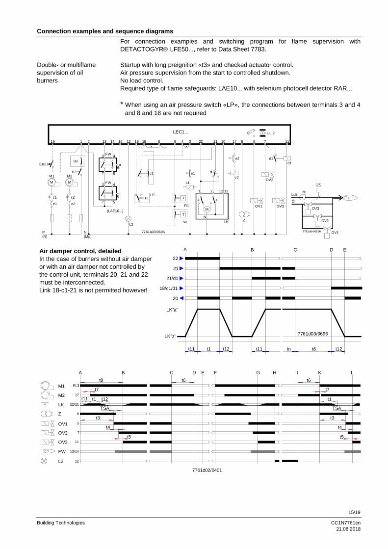
Connection examples and sequence diagramsFor connection examples and switching program for flame supervision withDETACTOGYRâ LFE50..., refer to Data Sheet 7783.
Startup with long preignition «t3» and checked actuator control.Air pressure supervision from the start to controlled shutdown.No load control.Required type of flame safeguards: LAE10... with selenium photocell detector RAR...
* When using an air pressure switch «LP», the connections between terminals 3 and 4and 8 and 18 are not required
1 2 13 14 15 12 19 18 8 9 4 3 22 21 20 17 6 5 7 11
UL.2
M1 M2
M M
c1
e1
P(R)
c2
e2
H
N(Mp)
L2
LPP
c1
*
W
R1
T
T
*
e1
c1
1 2 12 11
a z
M
NLK
e2
d1c2
Z
OV1
OV2
OV3
d1d1
LEC1...
7761a03/0696
EK2
16
3
7
4
56
FW
3
7
4
56
FW
(LAE10...)
SB
Luft
Öl
M
LK
OV3
OV2
OV17761a04/0696
Air damper control, detailedIn the case of burners without air damperor with an air damper not controlled bythe control unit, terminals 20, 21 and 22must be interconnected.Link 18-c1-21 is not permitted however!
t11 t1 t12 t11 tn t6 t12
22
21
21/d1
18/c1/d1
20
LK"a"
LK"z"
A B C D E
7761d03/0696
A Bt8
t7
t11 t1 t12
TSA
t3
t4
t5
M1
M2
LK
Z
OV1
OV2
OV3
FW
L2
Kl.3
17
22/21
6
5
7
11
13/14
12
Ct6
D E F G Ht6
t7
t1
TSA
K L
7761d02/0401
I
t3
t5
t4
Double- or multiflamesupervision of oilburners
16/19
Building Technologies CC1N7761en21.08.2018
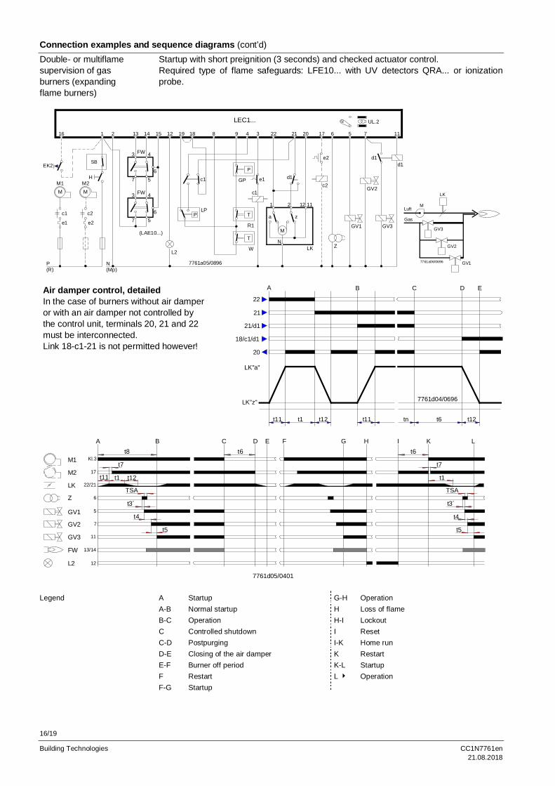
Connection examples and sequence diagrams (cont’d)Startup with short preignition (3 seconds) and checked actuator control.Required type of flame safeguards: LFE10... with UV detectors QRA... or ionizationprobe.
1 2 13 14 15 12 19 18 8 9 4 3 22 21 20 17 6 5 7 11
UL.2
M1 M2M M
c1
e1
P(R)
c2
e2
H
N(Mp)
L2
LPP
c1
W
GP
T
T
e1
c1
1 2 12 11
a z
M
NLK
e2
d1c2
Z
GV1
GV2
GV3
d1d1
LEC1...
7761a05/0896
EK2
16
3
7
4
56
FW
3
7
4
56
FW
(LAE10...)
SBP
R1
Luft
Gas
M
LK
GV3
GV2
GV17761a06/0696
Air damper control, detailedIn the case of burners without air damperor with an air damper not controlled bythe control unit, terminals 20, 21 and 22must be interconnected.Link 18-c1-21 is not permitted however!
t11 t1 t12 t11 tn t6 t12
22
21
21/d1
18/c1/d1
20
LK"a"
LK"z"
A B C D E
7761d04/0696
A Bt8
t7
t11 t1 t12
TSA
t3´
t4
t5
M1
M2
LK
Z
GV1
GV2
GV3
FW
L2
Kl.3
17
22/21
6
5
7
11
13/14
12
Ct6
D E F G Ht6
t7
t1
TSA
K L
7761d05/0401
I
t3´
t5
t4
A Startup G-H OperationA-B Normal startup H Loss of flameB-C Operation H-I LockoutC Controlled shutdown I ResetC-D Postpurging I-K Home runD-E Closing of the air damper K RestartE-F Burner off period K-L StartupF Restart L4 OperationF-G Startup
Double- or multiflamesupervision of gasburners (expandingflame burners)
Legend
17/19
Building Technologies CC1N7761en21.08.2018
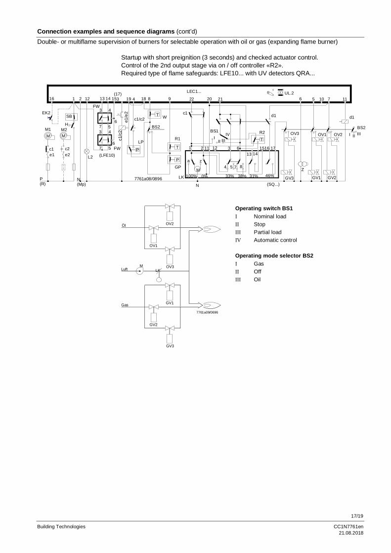
Connection examples and sequence diagrams (cont’d)Double- or multiflame supervision of burners for selectable operation with oil or gas (expanding flame burner)
Startup with short preignition (3 seconds) and checked actuator control.Control of the 2nd output stage via on / off controller «R2».Required type of flame safeguards: LFE10... with UV detectors QRA...
P
HM1 M2M M
c1e1
c2e2
P(R)
1 2 12 15(17)
3 18 8 9 22
N(Mp)
L2
c1/c
2e1
/e2
c1/c2
LP
P
T W
GP
c1
1
a
LK 100%M
2
z
11 12 3 613 14
15 17
20 21 6
BS1I
II IIIIV
T
R2
d1
46%31%38%
16
N
0% 33%
4 5 7 8
(SQ...)GV3
Z
d1
UL.211
7761a08/0896
LEC1...
1916 13 14
3
7
4
56
FW
3
7
4
56FW
(LFE10)
T
R1
4
BS2OV3
GV1
OV1
5
GV2
OV2
710
BS2I II III
EK2SB
Luft
Gas
M
GV2
LK
7761a09/0696
GV3
GV1
OV1
OV3
OV2Öl
Operating switch BS1I Nominal loadII StopIII Partial loadIV Automatic control
Operating mode selector BS2I GasII OffIII Oil
18/19
Building Technologies CC1N7761en21.08.2018
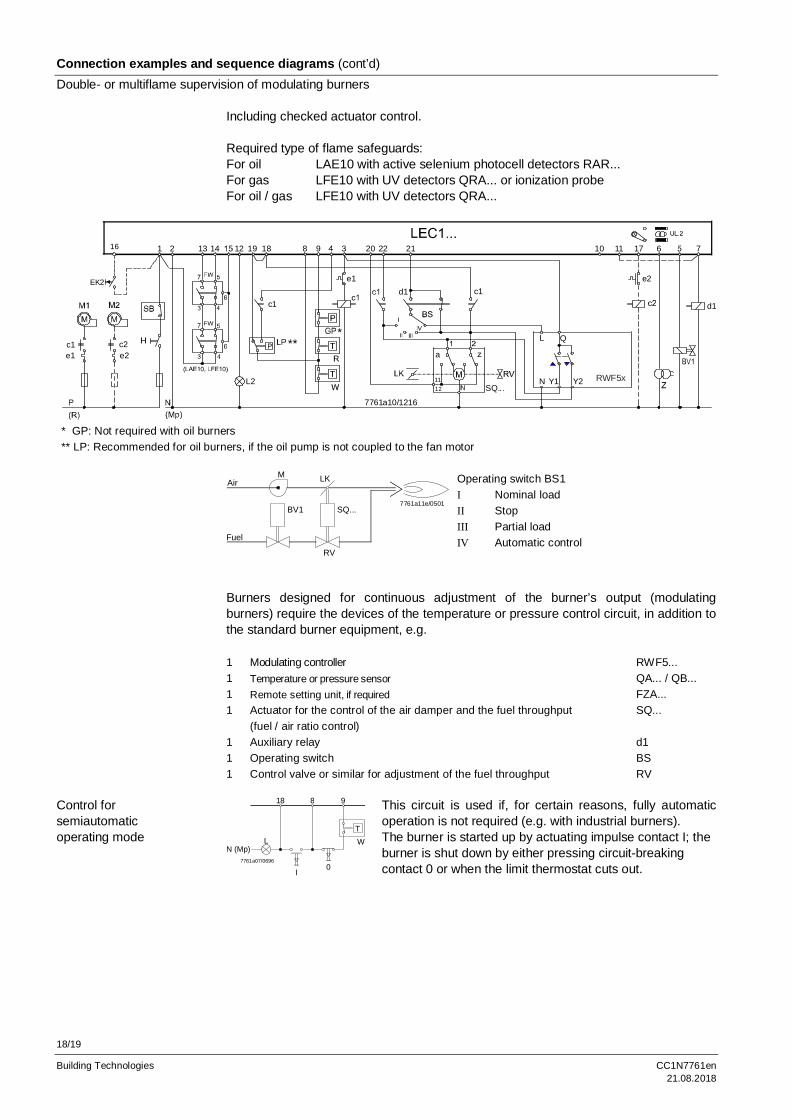
Connection examples and sequence diagrams (cont’d)Double- or multiflame supervision of modulating burners
Including checked actuator control.
Required type of flame safeguards:For oil LAE10 with active selenium photocell detectors RAR...For gas LFE10 with UV detectors QRA... or ionization probeFor oil / gas LFE10 with UV detectors QRA...
1 2 13 14 12 19 18 8 9 20 22 21
d1e1
c1
10 11 17 6 7
e2
d1c1
c1e1
c2e2
L2
a
1112 SQ...
7761a10/1216
EK2
16
FW
***
RWF5x
QL
N Y1 Y2
* GP: Not required with oil burners** LP: Recommended for oil burners, if the oil pump is not coupled to the fan motor
Air
Fuel
M
BV1
RV
SQ...
LK
7761a11e/0501
Operating switch BS1I Nominal loadII StopIII Partial loadIV Automatic control
Burners designed for continuous adjustment of the burner’s output (modulatingburners) require the devices of the temperature or pressure control circuit, in addition tothe standard burner equipment, e.g.
1 Modulating controller RWF5...1 Temperature or pressure sensor QA... / QB...1 Remote setting unit, if required FZA...1 Actuator for the control of the air damper and the fuel throughput
(fuel / air ratio control)SQ...
1 Auxiliary relay d11 Operating switch BS1 Control valve or similar for adjustment of the fuel throughput RV
18 8 9
LN (Mp)
I0
WT
7761a07/0696
This circuit is used if, for certain reasons, fully automaticoperation is not required (e.g. with industrial burners).The burner is started up by actuating impulse contact I; theburner is shut down by either pressing circuit-breakingcontact 0 or when the limit thermostat cuts out.
Control forsemiautomaticoperating mode
19/19
Building Technologies CC1N7761en21.08.2018
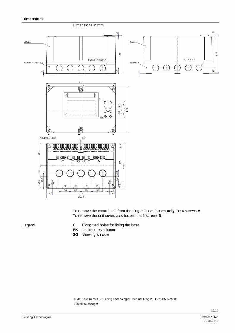
DimensionsDimensions in mm
1 1711
62
Pg11/3/4"-16DNF
A210
B A
A B A
13,5
14,5 25
2514
0
4,5
SG
EK17
,218
,94,
517
,210
5
17,7
139,
4
93333333317,7 174
209,4
46,7
36,7
3369
,7
C C
C
7761m01/1102
LEC1...
AGG41041713 (EC)
1 1711
62
M16 x 1,5AGG12.1
LEC1...
To remove the control unit from the plug-in base, loosen only the 4 screws A.To remove the unit cover, also loosen the 2 screws B.
C Elongated holes for fixing the baseEK Lockout reset buttonSG Viewing window
Legend
ã 2018 Siemens AG Building Technologies, Berliner Ring 23, D-76437 RastattSubject to change!
Related Documents