The Open Mechanical Engineering Journal, 2008, 2, 75-83 75 1874-155X/08 2008 Bentham Open Open Access Parametric Study of a Centrifugal Pump Impeller by Varying the Outlet Blade Angle E.C. Bacharoudis *,1 , A.E. Filios 2 , M.D. Mentzos 1 and D.P. Margaris 1 1 Fluid Mechanics Laboratory, Mechanical Engineering and Aeronautics Department, University of Patras, Patras, Greece 2 Fluid Mechanics and Turbomachinery Laboratory, Department of Mechanical Engineering Educators, School of Pedagogical and Technological Education, Athens, Greece Abstract: The pump design is facilitated by the development of computational fluid dynamics and the complex internal flows in water pump impellers can be well predicted. Various parameters affect the pump performance and energy consumption. The impeller outlet diameter, the blade angle and the blade number are the most critical. The present paper describes the simulation of the flow into the impeller of a laboratory pump in a parametric manner. In this study, the performance of impellers with the same outlet diameter having different outlet blade angles is thoroughly evaluated. The one-dimensional approach along with empirical equations is adopted for the design of each impeller. The predicted performance curves result through the calculation of the internal flow field and a successful correlation of local and global parameters. The numerical solution of the discretized three-dimensional, incompressible Navier-Stokes equations over an unstructured grid is accomplished with a commercial CFD finite-volume code. For each impeller, the flow pattern and the pressure distribution in the blade passages are calculated and finally the head-capacity curves are compared and discussed. Keywords: Centrifugal pump, Impeller, CFD, Numerical study. INTRODUCTION The complexity of the flow in a turbomachine is primaril y due to the three dimensional developed structures involving turbulence, secondary flows, unsteadiness etc. Initially, the design of a centrifugal pump was based mainly on empirical correlation, combination of model testing and engineering experience. Nowadays, the design demands a detailed understanding of the internal flow during design and off-design operating conditions. Computational fluid dynamics (CFD) have successfully contributed to the prediction of the flow through pumps and the enhancement of their design. The complex internal flow at the outlet of the impeller appears a circumferential distortion due to the asymmetric shape of the spiral volute and tongue, especially at off design operating points. Moreover the rotor-volute interacti on causes th e appearance of dynamic effects which influence the overall pump performance. The non-uniform flow conditions and particularly the pressure field lead to the development of unbalanced radial forces. All these characteristics are crucial for the pump design. The predictions of the performance in combination with the investigation of the complex internal flow through the impeller have developed to fields of intense research. Various researchers have considerably contributed to revealing the flow mechanisms inside centrifugal impellers with spiral volute or vaned diffuser volute aiming to the *Address correspondence to this author at the Fluid Mechanics Laboratory, Mechanical Engineering and Aeronautics Department, University of Patras, Patras, Greece; Tel: 0030-2610997193; E-mail: [email protected] design of high performance centrifugal turbomachines. The reported works by Eckardt [1], Johnson et al. [2], Kjork et al. [3], Denton [4], Dawes [5], Casey et al. [6], Bansod et al. [7], Krain et al. [8], Farge et al. [9] and Zhang et al. [10] are an indicative collection of research efforts on the computation and the experimental verification of the flowfields within centrifugal impellers. The last decade research becomes more sophisticated, specifically recently, Hillewaert et al. [11], Gonzalez et al. [12-14], Byskov et al. [15], Meakhail et al. [16], Majidi [17] and Feng et al. [18] extended the prediction of the performance at various operating conditions, different from the normal one, taking into account the dynamic effects of the flow. Several algorithms have been proposed and developed, targeting to the numerical simulation of the flowfield of a centrifugal impeller. These algorithms apply either pressure based or density based methods for the solution of Navier- Stokes equations. Lakshminarayana [19], Rodi et al. [20] and Thakur et al. [21], provide a review of the techniques that are useful as an assessment of the state of the art. It is evident that there is a lot of research work at the numerical and experimental evaluation of the pump flow field, however the study of important manufacturing parameters that influence the performance of a pump is infrequently available in the open literature. Kergourlay et al. [22] studied the influence of adding splitter blades in a hydraulic centrifugal pump impeller. A comparison between impellers with and without splitters and the predicted characteristic curves were presented. Gonzalez et al. [13] tested two centrifugal pump impellers with different outlet diameters for the same volute. A detailed description of the influence of the radial gap between impeller exit and tongue was presented. Anagnostopoulos [23]

Welcome message from author
This document is posted to help you gain knowledge. Please leave a comment to let me know what you think about it! Share it to your friends and learn new things together.
Transcript

8/6/2019 75TOMEJ
http://slidepdf.com/reader/full/75tomej 1/9
The Open Mechanical Engineering Journal, 2008, 2, 75-83 75
1874-155X/08 2008 Bentham Open
Open Access
Parametric Study of a Centrifugal Pump Impeller by Varying the OutletBlade Angle
E.C. Bacharoudis*,1
, A.E. Filios2, M.D. Mentzos
1and D.P. Margaris
1
1Fluid Mechanics Laboratory, Mechanical Engineering and Aeronautics Department, University of Patras, Patras,
Greece
2Fluid Mechanics and Turbomachinery Laboratory, Department of Mechanical Engineering Educators, School of
Pedagogical and Technological Education, Athens, Greece
Abstract: The pump design is facilitated by the development of computational fluid dynamics and the complex internal
flows in water pump impellers can be well predicted. Various parameters affect the pump performance and energy
consumption. The impeller outlet diameter, the blade angle and the blade number are the most critical. The present paper
describes the simulation of the flow into the impeller of a laboratory pump in a parametric manner. In this study, the
performance of impellers with the same outlet diameter having different outlet blade angles is thoroughly evaluated. The
one-dimensional approach along with empirical equations is adopted for the design of each impeller. The predicted
performance curves result through the calculation of the internal flow field and a successful correlation of local and global
parameters. The numerical solution of the discretized three-dimensional, incompressible Navier-Stokes equations over an
unstructured grid is accomplished with a commercial CFD finite-volume code. For each impeller, the flow pattern and the
pressure distribution in the blade passages are calculated and finally the head-capacity curves are compared and discussed.
Keywords: Centrifugal pump, Impeller, CFD, Numerical study.
INTRODUCTION
The complexity of the flow in a turbomachine isprimarily due to the three dimensional developed structuresinvolving turbulence, secondary flows, unsteadiness etc.Initially, the design of a centrifugal pump was basedmainly on empirical correlation, combination of modeltesting and engineering experience. Nowadays, the designdemands a detailed understanding of the internal flow
during design and off-design operating conditions.Computational fluid dynamics (CFD) have successfullycontributed to the prediction of the flow through pumpsand the enhancement of their design.
The complex internal flow at the outlet of the impellerappears a circumferential distortion due to the asymmetricshape of the spiral volute and tongue, especially at off design operating points. Moreover the rotor-voluteinteraction causes the appearance of dynamic effects whichinfluence the overall pump performance. The non-uniformflow conditions and particularly the pressure field lead tothe development of unbalanced radial forces. All thesecharacteristics are crucial for the pump design. Thepredictions of the performance in combination with theinvestigation of the complex internal flow through theimpeller have developed to fields of intense research.
Various researchers have considerably contributed torevealing the flow mechanisms inside centrifugal impellerswith spiral volute or vaned diffuser volute aiming to the
*Address correspondence to this author at the Fluid Mechanics
Laboratory, Mechanical Engineering and Aeronautics Department,
University of Patras, Patras, Greece; Tel: 0030-2610997193; E-mail:
design of high performance centrifugal turbomachines. Thereported works by Eckardt [1], Johnson et al. [2], Kjork et al[3], Denton [4], Dawes [5], Casey et al. [6], Bansod et al. [7]Krain et al. [8], Farge et al. [9] and Zhang et al. [10] are anindicative collection of research efforts on the computationand the experimental verification of the flowfields withincentrifugal impellers.
The last decade research becomes more sophisticated
specifically recently, Hillewaert et al. [11], Gonzalez et al[12-14], Byskov et al. [15], Meakhail et al. [16], Majidi [17and Feng et al. [18] extended the prediction of theperformance at various operating conditions, different from thenormal one, taking into account the dynamic effects of theflow.
Several algorithms have been proposed and developedtargeting to the numerical simulation of the flowfield of acentrifugal impeller. These algorithms apply either pressurebased or density based methods for the solution of NavierStokes equations. Lakshminarayana [19], Rodi et al. [20] andThakur et al. [21], provide a review of the techniques that areuseful as an assessment of the state of the art.
It is evident that there is a lot of research work at thenumerical and experimental evaluation of the pump flow fieldhowever the study of important manufacturing parameters thainfluence the performance of a pump is infrequently availablein the open literature. Kergourlay et al. [22] studied theinfluence of adding splitter blades in a hydraulic centrifugapump impeller. A comparison between impellers with andwithout splitters and the predicted characteristic curves werepresented. Gonzalez et al. [13] tested two centrifugal pumpimpellers with different outlet diameters for the same volute. Adetailed description of the influence of the radial gap betweenimpeller exit and tongue was presented. Anagnostopoulos [23

8/6/2019 75TOMEJ
http://slidepdf.com/reader/full/75tomej 2/9
76 The Open Mechanical Engineering Journal, 2008, Volume 2 Bacharoudis et al
developed a numerical model for the simulation of the 3Dturbulent flow and investigated different impeller configurations by varying crucial design parameters.
The present ongoing research is concerned with theinfluence of the outlet blade angle in the performance of alaboratory centrifugal pump. The design and off-design performance characteristic curves, the local and globalvariables of the flow field and the resulted non-uniform
circumferential pressure field are numerically predicted for three shrouded radial impellers with different outlet bladeangle. The computational fluid dynamics analysis is carriedout with the commercial software package Fluent [24],which has been widely used in the field of turbomachineryand the simulation results, have been proven by Sun et al.
[25] and Gonzalez et al. [12] to be reliable.
THE PUMP STUDIED
The systematic research on the influence of the variousdesign aspects of a centrifugal pump in its performance inthe whole range of the flow rates requires numerical predictions and experiment. Recently, in the Fluid
Mechanics Laboratory of the University of Patras, a pumptest rig designed and already is in operation. The test rig is presently equipped with an industrial centrifugal pump thatit will be soon replaced by a laboratory pump with thecompletion of its manufacture. The laboratory pump volutehas been especially designed in a way that it can easily suitradial impellers of the same outlet diameter but differ invarious main design parameters such as the number of blades, the mean line geometry of the blade, the inlet andoutlet blade angles.
The volute of the laboratory centrifugal pump is of rectangular section with rounded corners and its diffuser extends in the radial direction. Three shrouded impellers of
constant width (b=20mm) with six untwisted blades backward facing have been designed according toPfleiderer method [26]. The blade length in the threeimpellers is almost equal. All impellers have the samediameters in suction and pressure side as well as the same blade’s leading edge angle (1=14 deg) and they vary in the blade’s trailing edge angle which is 2=20, 30 and 50 deg,respectively. The diameters of the impellers at the suctionand pressure side are D1=150mm and D2=280mm,respectively.
Fig. (1). A 3D image of the laboratory pump with the three radial
impellers.
The CAD model of the designed laboratory pump with thethree impellers and the absence of their front shroud for blade profile viewing purposes are shown in Fig. (1). In therotational speed (n) of 925rpm, the normal operation of thethree impellers is 0,0125m3/sec flow rate (Q) and according toone dimensional theory the estimated pump’s total head (H) i10m that results in the value 18,4 for the specific speed(nq=n·Q1/2/H3/4). At the normal operating point, the hydraulic
efficiency (H) of the pump reaches its maximum value 0,83.
GOVERNING EQUATIONS
The incompressible flow through the rotating impeller issolved in a moving frame of reference with constant rotationaspeed equal the rotational speed of the impeller. The flowthrough the stationary parts of the pump is solved in an inertiareference frame. The governing equations for the impeller areformulated below
ur= 0 … (1)
ur+ 2 u
r+ r = p + μ
eff 2
ur… (2)
where is the density of the fluid, p is the static pressure, ur ithe vector fluid velocity in the rotating system, is therotational speed and μeff is the dynamic effective viscositywhich is a linear combination of laminar and turbulenviscosity derived from k- model of turbulence. The last twoterms in the left hand side of equation (2) are the effects of theCoriolis and centrifugal forces due to the rotating frame oreference.
For the stationary parts of the centrifugal pump, thegoverning equations are formulated in the stationary referenceframe. The continuity equation remains the same, but themomentum equation reduces to
u = p + μeff
2u… (3)
where u is the vector fluid velocity in the stationary frame oreference.
The turbulence of the flow is modelled with standard k-model that is rated as the most used model that combinessimplicity, robustness and reasonable accuracy. Moreover, ihas been tested in a wide range of industrial flows showingsatisfactory results. The differential transport equations for theturbulence kinetic energy and turbulence dissipation rate are:
uk = μ +μ
t
k
k
+G
k … (4)
u = μ +μ
t
+C1
k G
k C
22
k … (5)
μt= C
m
k 2
… (6)
where u is the local velocity vector, k is the turbulent kineticenergy, is the dissipation rate, μ is the laminar viscosity, μt ithe turbulent viscosity, Gk represents the generation oturbulent kinetic energy due to the mean velocity gradients,

8/6/2019 75TOMEJ
http://slidepdf.com/reader/full/75tomej 3/9
Centrifugal Pump Impeller by Varying the Outlet Blade Angle The Open Mechanical Engineering Journal, 2008, Volume 2 77
and are the turbulent Prandtl numbers and C1=1,44,C2=1,92 and Cm=0,09 are the constants of the model.
COMPUTATIONAL ISSUES
Geometry and Grid
The numerical treatment of the radial pump implies thespatial discretization of the flow domain. All gaps between
the impeller shroud and the pump casing are neglected inthe present numerical simulation. The whole domainconsists of three sub-domains or zones. The first and thirdzones are stationary while the second zone thatincorporates the blade is moving with the applied rotationalspeed of n=925 rpm.
The first zone represents the suction or inlet pipe that is100 mm in diameter and the third zone is the discharge oroutlet portion where the flow is fully developed with a lesspossible reacting outlet boundary condition. Theintermediate zone consists of the eye and the impeller of the pump. The three sub-domains were separated furtherby additional inner faces forming different blocks. In thisway, the density and the quality of the cells in local flowfield regions can be suitably controlled and handleddepending on pressure gradients and velocities.
Fig. (2). Sketch of the unstructured mesh of the pump.
Fig. (3). Details of the unstructured mesh in the region of the
tongue.
Fig. (4). The structured hexahedral cells around the blades combined
with the unstructured mesh in the blade passage.
The geometry and the mesh of the computational pumpdomain were generated with Fluent’s pre-processor, Gambit
[27]. Unstructured wedges are generated to define the inlet andoutlet zones. An unstructured mesh with tetrahedral cells ialso used for the zones of impeller and volute as shown in Fig(2). The mesh is refined in the near tongue region of the volute(see Fig. (3)), as well as in the regions close to the leading and
trailing edge of the blades. Around the blades, structuredhexahedral cells are generated, as shown in Fig. (4). Thoughthe size of the cells in the wall regions is not adequate toresolve the viscosity-affected region inside the boundary layerthe appropriate number of cells exists inside the boundarylayer for the approach of standard wall functions. The latterprovides correct values for the pump performance and allows adetailed analysis of the main phenomena involved.
Remarks on the Numerical Simulation
All the calculations have been performed with Fluent
CFD software package [24] that utilizes the finite volumemethod for the solution of the steady 3D incompressible
Navier-Stokes equations, including the centrifugal force sourcein the impeller. Turbulence is modelled with the selection othe standard k- model. The involved parameters regarding theturbulence intensity and the hydraulic diameter, in the lack orealistic turbulent inflow conditions in industrial applicationsare estimated with values of 5% and D/2, respectively. Thepressure-velocity coupling is performed through the SIMPLEalgorithm. Second order, upwind discretization is used foconvections terms and central difference schemes for diffusionterms.
The applied boundary conditions involve the extension othe computational domain by adding a reasonable length at theinlet and outlet pipes of the centrifugal pump in order to bettesimulate the pumping circuit influence. At the inlet zone, the
axial velocity is a constant based on the through flow for thepump. The absolute tangential velocity at the inlet is zerowhich implies, in the rotating frame, that the relative velocityis –r and the radial velocity is zero. At the exit of thedischarge pipe, assuming a fully developed turbulent flow, apractically zero velocity gradient is set. The walls of the modeare stationary with respect to their respective frame oreference, and the no slip condition is applied.
Although grid size is not adequate to investigate locaboundary layer variables, global ones are well captured. Fosuch calculations wall functions, based on the logarithmic lawhave been used.

8/6/2019 75TOMEJ
http://slidepdf.com/reader/full/75tomej 4/9
78 The Open Mechanical Engineering Journal, 2008, Volume 2 Bacharoudis et al
Since the problem involves both stationary and movingzones, the multiple reference frame model has beenselected. It is a quasi-steady state approximation in whichindividual cell zones move at different rotational speeds.As the rotation of the reference frame and the rotationdefined via boundary conditions can lead to large complexforces in the flow, calculations may be less stable as thespeed of rotation and hence the magnitude of these forces
increases. To control this undesirable effect, each run startswith a low rotational speed and then the rotation is slowlyincreased up to the desired level.
The simulations were executed in a 3GHz Pentium IVPC. The number of iterations adjusted to reduce the scaledresidual below the value of 10
-5, which is the criterion of
convergence. For each run, the observation of theintegrated quantities of total pressure, at suction as well asat discharge surface was appointed for the convergence of the solution. In many cases this drives the residuals inlower values than the initially set value. Depending on thecase, the convergence was achieved at different iterations,as the result at a specific mass-flow was used to initializethe computations at another mass-flow. Aiming to smoothconvergence, various runs were attempted by varying theunder-relaxations factors. In that way a direct controlregarding the update of computed variables throughiterations, was achieved. Initializing with low values for the first iterations steps and observing the progress of theresiduals, their values were modified for accelerating theconvergence.
NUMERICAL RESULTS
The outlet angle of three different impellers iscorrelated with the slope of the H-Q performance curve of each impeller. Increasing the outlet blade angle, the shapeof the curve becomes smoother and flatter. This fact is
expected and is consistent with theory, i.e.
H = μH
u2
2
g1
cm3
u2
cot2
… (7)
where μ is the slip factor [28], H is the hydraulicefficiency, u2 is the peripheral velocity at the outlet sectionof the impeller, cm3 is the meridian velocity at the exit of impeller passage and 2 is the outlet blade angle.
Equation (7) enables the ascertainment of the effect of the two design parameters cm3/u2 and 2 on the total head.If cm3/u2 is reduced, then the total head is increased.Certainly, the effect of the vane discharge angle is not so
straightforward. If the 2 angle increases, then the totalhead increases, too. However, the effect of increase theangle 2 is partly cancelled since the slip factor formulasindicate that larger angle 2 results to the decrease of theslip factor value. The variation of the slip factor affects theshape of the H-Q curve and it is noticeable for blade anglesgrater than 25 deg.
The later is in agreement with the results of thenumerical prediction of the H-Q curves for the examinedimpellers, which are shown in Fig. (5a). The ordinate is thenon-dimensional total head of the pump while the abscissais the non-dimensional flow rate. The Q N=58,5 m
3/h and
H N=8,93 m are the CFD predicted nominal volume rate andthe nominal total head for the 2=20 deg impeller, respectively
Fig. (5a). Predicted head curves for the examined pump impellers.
Fig. (5b). Predicted hydraulic efficiency curves for the examined
pump impellers.
The nominal flow rate is defined by the point in which thehydraulic efficiency of the pump reaches its maximum value
The variation of the hydraulic efficiency against the nondimensional flow rate for the numerically studied impellersare shown in Fig. (5b). At the nominal flow rate the value othe hydraulic efficiency is ranged between 0,81 and 0,845 fothe three impellers which is in reasonable accuracy with the predicted value according to the applied design method. A50% reduction of the volume rate from its nominal valueresults to 20%, 25% and 28% drop of the H relative to theinominal value for the impellers with 2=20, 30 and 50degrespectively. A 50% increase of the volume rate from thenominal point leads to 25%, 15% and 15% drop of the H
relative to the nominal one for the three impellers respectively

8/6/2019 75TOMEJ
http://slidepdf.com/reader/full/75tomej 5/9
Centrifugal Pump Impeller by Varying the Outlet Blade Angle The Open Mechanical Engineering Journal, 2008, Volume 2 7
The curve of the hydraulic efficiency for Q<QN decreasesmore rapidly for the impellers with 2=30 deg and 50 degthan for 2=20deg. The opposite happens for Q>QN wherethe H curve of the 2=20 deg impeller is steeper. Thecomparison of the hydraulic efficiency of the threeimpellers at Q=QN shows that the increase of the outletangle more than 10 deg till to 30 deg reduce it almost 3%.
Fig. (6). Percentage variation of the head (solid lines) and
hydraulic efficiency (dash lines) curves with outlet blade angle
for the examined impellers.The shift of the performance curves due to the variation
of the outlet blade angle may be expressed in terms of percentage variation with reference of the correspondingvalues H/HN and H at nominal capacity for the 2=20 degimpeller, as shown in Fig. (6). Thus, at nominal capacity, a10 deg increase of the 2 angle causes a 4,2% increase of the head and a 3,9% decrease of the hydraulic efficiency. If the 2 increases 30deg, i.e. from 20 deg to 50 deg, then thehead increases 6,2% and the hydraulic efficiency decreases4,5%.
Besides the predicted performance curves of the studiedimpellers, the assessment of the local characteristics of the
internal flow field is accomplished. The static pressurefields for the plane near the back shroud for the two of thestudied impellers are shown in Fig. (7). At constant radialposition, it is confirmed that the static pressure drops fromthe pressure side to the suction side of the impeller bladeand this pressure drop reduces at the exit of the bladepassage. Moreover, the static pressure patterns are not thesame in the planes between the hub and the shroud. Thevariation is noticed in the pressure contour field of thelateral surfaces of the blades. The observed pressurevariation does not entail any additional losses in the pumpand simply implies that each blade can only transmit afixed amount of energy and certainly it is lower than the
value prescribed by Euler’s equation. Qualitatively, thepatterns are similar for the three examined impellers. As it iexpected, the variations are focused on the static pressurevalues that become larger with the increase of the outlet bladeangle.
Fig. (7). Relative static pressure contours (atm) at QN for the 2=20
deg (a) and 2=50 deg (b) impellers.
The minimum value of the static pressure inside theimpeller is located at the leading edge of the blades at the
suction side except for the blade with trailing edge, which endup at the region of the tongue. For that blade, the minimumpressure is located at the leading edge of the blade at thepressure side primarily due to the blade - tongue interactionAnother reason for the appearance of low local pressures at thepressure side of the blade is related with the geometry and thedesign method of the blade, which permits the development osuch pressure contours. Hence, the minimum pressure iobserved at these regions. The same situation stands for flowrates greater or lower than the nominal one, as well as fodifferent outlet angles.
Fig. (8). The absolute velocities (m/s) in the region of the tongue fo
the 2=20 deg impeller.

8/6/2019 75TOMEJ
http://slidepdf.com/reader/full/75tomej 6/9
80 The Open Mechanical Engineering Journal, 2008, Volume 2 Bacharoudis et al
Fig. (9). The relative velocities (m/s) at the trailing edge of the
blade with 2=20 deg (a) and 2=50 deg (b).
The flow close to the tongue and at the designoperation is shown in Fig. (8). The pattern verifies that the
position of the stagnation point is placed in the middle of thetongue edge and it is in agreement with published data [13]Furthermore, the outlet blade angle affects and changes therelative velocity patterns. As the 2 increases, a recirculationzone establishes at the trailing edge of the blade as Fig. (9shows.
Significant variations in the absolute velocity field in theblade passage are displayed when the impeller operates off
design. Fig. (10) shows the absolute velocity vectors in theleading edge of one blade for the three studied impellers witheach one operating in nominal capacity or at the edges of theexamined capacity range. When the volume flow rate inominal or more than nominal, the fluid flows smoothlythrough the impeller passage, except for the flow passagewhich ends up at the region of tongue. The flow direction incombination with the blade curvature exhibits a weak vortex athe pressure side of the blade just downstream the leading edgegiving reasons to the appearance of low pressure in this regionReversely, when the impeller operates in volume flow rateless than nominal, a recirculation zone is established in theleading edge of each blade.
The absolute velocity patterns which are shown in Fig. (10do not suggest that the velocity distribution is uniform in theblade passage across the impeller width. Non uniformities aremainly present in the region of the leading edge and these areminimized in the outlet of the impeller. The unevennessvelocity distribution in the entrance of the blade passage is dueto the different wall shape of the hub and shroud as well as toinability of the fluid to adjust its path in the imposed entrancegeometry. The fluid elements in the inside of the turn have
Fig. (10). Captures of the absolute velocity patterns in the region of leading edge at the middle span plane for the three studied impellers in
design and off-design operation.
8/6/2019 75TOMEJ
http://slidepdf.com/reader/full/75tomej 7/9
Centrifugal Pump Impeller by Varying the Outlet Blade Angle The Open Mechanical Engineering Journal, 2008, Volume 2 8
smaller velocities than those in the outside of curvature.These non uniformities in the velocity distribution areamplified when the pump operates off-design andespecially when Q is less than QN where moreover theaforementioned inlet recirculation establishes.
Fig. (11). Secondary flow patterns at nominal flow in three planes
along the volute that suits the 2=20 deg (a) and 2=50 deg (b)
impellers.
Published research work [14] supports the presence of secondary flow along the duct of the volute, whichdetected for all impellers and all volume flow rates. Fig.
(11) shows a capture of the flow in the volute of the pumpthat operates in nominal flow rate and equipped with twoof the studied impellers. As the fluid approaches thedischarge, eddies are maintained with small changes of their size and core position.
Fig. (12). The relative static pressure (atm) contours inside the
laboratory pump.
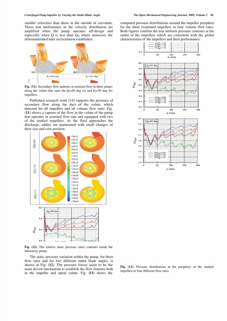
The static pressure variation within the pump, for threeflow rates and for two different outlet blade angles, isshown in Fig. (12). The pressure forces seem to be themain driven mechanism to establish the flow features bothin the impeller and spiral volute. Fig. (13) shows the
computed pressure distributions around the impeller peripheryfor the three examined impellers in four volume flow ratesBoth figures confirm the non uniform pressure contours at theoutlet of the impellers which are consistent with the globacharacteristics of the impellers and their performance.
Fig. (13). Pressure distributions at the periphery of the studied
impellers in four different flow rates.

8/6/2019 75TOMEJ
http://slidepdf.com/reader/full/75tomej 8/9
82 The Open Mechanical Engineering Journal, 2008, Volume 2 Bacharoudis et al
For flow rates lower than nominal, the pressure reachesits lowest value directly in front of the tongue and starts toincrease around the periphery of the impeller, taking itsmaximum value just behind the tongue. When the flow rateapproaches the nominal, the pressure distribution issmoothed achieving the most uniform contour in nominalvolume flow rate. At higher flow rates, the pressuredecreases gradually from its maximum value in front of the
tongue to a minimum value just behind the tongue. Theaforementioned verify remarkable influence of the tonguein the pressure field inside the pump.
Fig. (14). Computed radial forces in the examined impellers in
design and off-design operation.
The non uniform static pressure field around theimpeller results in a radial force which is calculated by the
integration of the pressure force distribution. For thestudied impellers operating in nominal volume flow rateand away from it, the computed radial forces (FR) dividedby the impeller shroud area (A) are shown in Fig. (14).
For the 2=20deg impeller with its standard volutecasing, a “V” shape diagram of the radial force is obtained.For volume flow rates close to the nominal, a moreuniform pressure distribution exists which implies lessradial forces. On the other hand, far from the designoperation the non uniformity is quite profound whichresults in larger forces. The minimum radial forces for thatcase were calculated near the best efficiency point asexpected. The same trend is observed for the other twoimpellers with outlet blade angle 2=30 and 50 deg. It isremarkable the shift of the minimum radial force to higherflow rates. The shift from the nominal point has beenreported by researchers in literature and it has beenconfirmed with experiments [13]. It is explained by the factthat the pressure distribution Fig. (13) becomes moreuniform as the exit angle of the blade increases in highflow rates. However, the simplifications of the compu-tational pump geometry in comparison with the real one(no sided rooms for leakage flow) and the steady stateapproach should be taken into consideration because theyaffect the position of the minimum force. When Q1,5 QN the pressures around the 2=30 and 50 deg impellers are
varied almost around a mean value, which is not observed fo2=20 deg impeller. For blade angles above 30 deg and flowrates higher than 1,5 the radial force increases, displaying thecharacteristic “V” shape.
CONCLUDING REMARKS
A laboratory pump that can suit radial impellers with thesame diameter has been designed. Initially, three shroudedimpellers with outlet blade angle 20 deg, 30 deg and 50 degrespectively were designed and with the aid of computationaflow dynamics, the flow patterns through the pump as well asits performance for flow rates in design and off-designoperation are predicted. On the assumption of the onedimensional flow theory, the pump was designed to operate anominal characteristics Q=45 m
3 /h and H=10 m, when th
rotational speed is 925 rpm.
The CFD predicted value of the head at the nominal flowrate is approximately H=9 m. There is a shift of the numericanominal flow rate towards greater values and a discrepancy o10% between the theoretical head and the predicted numericahead. One reason for this shift is due to the fact that Pfleidere
design method does not take care of the complicated threedimensional flow structures and empirical formulas are appliedfor the account of hydraulic losses. Consequently, the increaseof the nominal flow rate causes a reduction in the total head othe pump. So the discrepancy between theoretical andnumerical values can be explained.
The numerical simulations seem to predict reasonably thetotal performance and the global characteristics of thelaboratory pump. The influence of the outlet blade angle on theperformance is verified with the CFD simulation. As the outleblade angle increases the performance curve becomesmoother and flatter for the whole range of the flow ratesWhen pump operates at nominal capacity, the gain in the head
is more than 6% when the outlet blade angle increases from 20deg to 50 deg. However, the above increment of the head irecompensed with 4,5% decrease of the hydraulic efficiencyWhen the pump operates off-design, the percentage raise othe head curve, due to the increment of the outlet blade angleis larger for high flow rates and becomes smaller for flow rateQ/QN<0,65. Moreover, at high flow rates, the increase of theoutlet blade angle causes a significant improvement of thehydraulic efficiency.
Further research work is planned to complete this studythrough the validation of the CFD predictions withexperimental data and simultaneously to investigate othecrucial design parameters for the laboratory pumpperformance.
REFERENCES
[1] D. Eckardt, “Detailed flow investigations within a high-speecentrifugal compressor impeller”, ASME Journal of Flu
Engineering , vol. 98, pp. 390-402, 1976.[2] M. W Johnson, and J. Moore, “The development of wake flow in a
centrifugal impeller”, ASME Journal of Engineering for Power, vo102, pp. 382-390, 1980.
[3] A. Kjork, and L . Lofdahl, “Hot-wire measurement inside a centrifugaimpeller”, ASME Journal of Fluids Engineering, vol. 111, pp. 363
368, 1989.[4] J.D. Denton, “The calculation of three-dimensional viscous flow
through multistage turbomachinery”, ASME Journal
Turbomachinery,vol. 114, pp. 18-26, 1992.

8/6/2019 75TOMEJ
http://slidepdf.com/reader/full/75tomej 9/9
Centrifugal Pump Impeller by Varying the Outlet Blade Angle The Open Mechanical Engineering Journal, 2008, Volume 2 83
[5] M.W. Dawes, “Toward improved through flow capability: the
use of three-dimensional viscous flow solvers in a multistageenvironment”, ASME Journal of Turbomachinery 114, pp. 8-17,
1992.[6] M.V. Casey, P. Dalbert, and P. Roth, “The use of 3D viscous
flow calculations in the design and analysis of centrifugalcompressors”, ASME Journal of Turbomachinery, vol. 114, pp.
27-37, 1992.[7] P. Bansod, and C.M. Rhie, “Computation of flow through a
centrifugal impeller with tip leakage”, AIAA Paper No 90-2021,
1990.[8] H. Krain, and W. Hoffman, “Verification of an impeller by laser
measurement and 3D viscous flow calculations”, ASME Paper
89-GT-150, 1989.[9] T.Z. Farge, and M.W. Johnson, “The effect of backswept blading
on the flow in a centrifugal compressor impeller”, ASME Paper 90-GT-231, 1990.
[10] M.J. Zhang, C.G. Gu, and Y.M. Miao, “Numerical study of theinternal flow field of a centrifugal impeller”, ASME Paper 94-
GT-357, 1994.[11] K. Hillewaert and R.A. Van den Braembussche, “Numerical
simulation of impeller-volute interaction in centrifugalcompressors”, ASME Journal of Turbomachinery, vol. 121, pp.
603-609, 1999.[12] J. Gonzalez, J. Fernandez, E. Blanco, and C. Santolaria,
“Numerical simulation of the dynamic effects due to impeller-volute interaction in a centrifugal pump”, ASME Journal of
Fluids Engineering, vol. 124, pp. 348-355, 2002.[13] J. Gonzalez, J. Parrondo, C. Santolaria, and E. Blanco, “Steady
and unsteady forces for a centrifugal pump with impeller totongue pump variation”, ASME Journal of Fluids Engineering,
vol. 128, pp. 454-462, 2006.[14] J. Gonzalez, and C. Santolaria, “Unsteady flow structure and
global variables in a centrifugal pump”, ASME Journal of Fluids
Engineering , vol. 128, pp. 937-946, 2006.
[15] R. K. Byskov, C. B. Jacobsen, and N. Pedersen, “Flow in acentrifugal pump impeller at design and off-design conditions-
Part II: Large Eddy Simulations”, ASME Journal of Fluids
Engineering , vol. 125, pp. 73-83, 2003.
[16] T. Meakhail and S.O. Park, “A study of impeller-diffuser-volut
interaction in a centrifugal fan”, ASME Journal of Turbomachinery
vol. 127, pp. 84-90, 2005.
[17] K. Majidi, “Numerical study of unsteady flow in a centrifugal pump” ASME Journal of Turbomachinery, vol. 127, pp. 363-371, 2005.
[18] J. Feng, F.K. Benra and H.J. Dohmen, “Numerical investigation onpressure fluctuations for different configurations of vaned diffuse
pumps”, International Journal of Rotating Machinery, vol. 20072007.
[19] B. Lakshminarayana, “An assessment of computational fluid dynami
techniques in the analysis and design of turbomachinery”, ASME Journal of Fluids Engineering, vol. 113, pp. 315-352, 1991.
[20] W. Rodi, S. Majumdar, and B. Schonung, “Finite volume methods fo
two-dimensional incompressible flows with complex boundaries”Computer Methods in Applied Mechanics and Engineering, vol. 75
pp. 369-392, 1989.[21] S. Thakur, J. Wright, W. Shyy, J. Liu, H. Ouyang, and T. Vu
“Development of pressure-based composite multigrid methods focomplex fluid flows”, Program in Aerospace Science, vol. 32, pp
313-375, 1996.[22] G. Kergourlay, M. Younsi, F. Bakir and R. Rey, “Influence of splitte
blades on the flow field of a centrifugal pump: Test-analysicomparison”, International Journal of Rotating Machinery, vol. 2007
2007.[23] J. Anagnostopoulos, “CFD Analysis and design effects in a radia
pump impeller”, WSEAS Transactions on Fluid Mechanics, vol. 1 (7)pp. 763-770, 2006.
[24] Fluent Inc., http://www.fluent.com/.[25] J. Sun, and H. Tsukamoto, “Off-design performance prediction fo
diffuser pumps”, Journal of Power and Energy, Proceedings of I
Mech. E., Part A, vol. 215, pp. 191–201, 2001.
[26] C. Pfleiderer, Die Kreiselpumpen für Flüssigkeiten und Gas
Springer-Verlag, Berlin, 1961.
[27] Gambit: Computational Fluid Dynamics (CFD) Preprocessorhttp://www.fluent.com/software/gambit
[28] D. Japikse, W.D. Marscher and R.B. Furst, Centrifugal Pump Desig
and Performance. Concepts ETI, Inc., Vermont, USA, 1997.
Received: February 02, 2008 Revised: April 23, 2008 Accepted: May 26, 2008
© Bacharoudis et al.; Licensee Bentham Open.
This is an open access article licensed under the terms of the Creative Commons Attribution Non-Commercial License (http://creativecommons.org/licenses/by
nc/3.0/ ), which permits unrestricted, non-commercial use, distribution and reproduction in any medium, provided the work is properly cited.