NCR RealPOS™ 80c Release 1.2 Site Preparation Guide B005‐0000‐1360 Issue C

Welcome message from author
This document is posted to help you gain knowledge. Please leave a comment to let me know what you think about it! Share it to your friends and learn new things together.
Transcript

NCR RealPOS™ 80c Release 1.2
Site Preparation Guide
B005‐0000‐1360 Issue C

The product described in this book is a licensed product of NCR Corporation.
NCR is a registered trademark of NCR Corporation.
It is the policy of NCR Corporation (NCR) to improve products as new technology, components, software, and firmware become available. NCR, therefore, reserves the right to change specifications without prior notice.
All features, functions, and operations described herein may not be marketed by NCR in all parts of the world. In some instances, photographs are of equipment prototypes. Therefore, before using this document, consult with your NCR representative or NCR office for information that is applicable and current.
To maintain the quality of our publications, we need your comments on the accuracy, clarity, organization, and value of this book.
Address correspondence to:
Manger, Information Products NCR Corporation 2651 Satellite Blvd. Duluth, GA 30096
Copyright © 2002 By NCR Corporation Dayton, Ohio U.S.A. All Rights Reserved
i
Preface
This is a contractual document. It contains important warnings and confers important legal rights and obligations. You are advised to read it carefully.
It is the responsibility of the customer to ensure that all installation preparations are complete and in compliance with NCR specifications and requirements and all applicable national, state, or local codes, regulations, and laws.
Safety Requirements
The NCR 7456 Terminal must be connected to an AC outlet that is near the terminal and is easily accessible by the operator.
Warning: This unit contains hazardous voltages and should only be serviced by qualified service personnel.
The on/off switch is a logic switch only. The AC line voltage primaries are live at all times when the power cord is connected. Therefore, disconnect the AC power cord before opening the unit to install features or service this terminal.
Peripheral Usage The 7456 should be used only with peripheral devices that are recommended by NCR Corporation and are certified by the appropriate safety agency for the country of installation (UL, CSA, TUV, VDE).
ii
About this Book
This book provides site preparation information for NCR 7456 Terminal components. Peripheral component and AC wiring site preparation information is NOT provided in this book. The associated reference documents are listed in the Related Site Preparation Data section.
This book contains the information necessary for the preparation of a site conforming to the NCR specifications. It is very important that the site complies with the requirements specified in the document because, once the equipment has been installed, deficiencies in site preparation or the problems caused by these deficiencies are much more difficult to detect and correct. Further, failure to comply with these requirements or to take proper steps to protect equipment against risks identified in this document may cause serious damage to the equipment and to the customerʹs business.
In addition to the need to comply with the requirements specified, electrical wiring, and mechanical systems must also comply with all relevant codes, laws, and regulations.
It is important that the site be prepared by a customer or his agent who is fully conversant with the special requirements of electronic equipment. The responsibility of ensuring that the site is prepared in compliance with this document remains with the customer.
For information and guidance purposes only, a list is provided, in general terms, of those matters for which the customer is responsible. This list is not intended to be comprehensive, and in no way modifies, alters, or limits the responsibility of the customer for all aspects of adequate site preparation.
iii
NCR staff will be available to answer questions relating to the contents of this document except where:
• a customer has been notified that a full or partial consultancy service is available and/or that NCR will be willing to undertake a preliminary or final site survey and
• the customer shall have entered into a formal contract with NCR for provision of the same.
No comment, suggestion, or advice offered or not offered about preparation of the site nor any inspection of the site whether before or after preparation is to be taken as approval of the location of the site and equipment or its preparation and NCR will not be liable in respect of any comment, suggestion, or advice given by its staff or in respect to any failure to give advice.
Finally, only the customer can know the full extent of damage which may be caused to his business by reason of failure of the equipment which is to be installed. For this reason it is the customerʹs responsibility to ascertain the extent of any possible damage to his existing or planned business, and to effect full insurance in respect of it.

iv
v
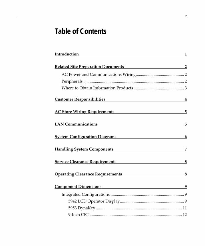
Table of Contents
Introduction 1
Related Site Preparation Documents 2
AC Power and Communications Wiring.............................................. 2 Peripherals ................................................................................................ 2 Where to Obtain Information Products ................................................ 3
Customer Responsibilities 4
AC Store Wiring Requirements 5
LAN Communications 5
System Configuration Diagrams 6
Handling System Components 7
Service Clearance Requirements 8
Operating Clearance Requirements 8
Component Dimensions 9
Integrated Configurations ...................................................................... 9 5942 LCD Operator Display............................................................. 9 5953 DynaKey .................................................................................. 11 9‐Inch CRT........................................................................................ 12

vi
Base Unit ................................................................................................. 12 Cash Drawers ......................................................................................... 13
NCR 2182 .......................................................................................... 13 NCR 2189 .......................................................................................... 13 NCR 2183 .......................................................................................... 14
Displays ................................................................................................... 15 7452‐K309 9‐Inch Monochrome CRT (497‐0418913).................... 15 7452‐K404 9‐Inch Monochrome CRT (497‐0418913).................... 16 7452‐K419 15‐Inch Monochrome CRT (497‐0414126).................. 17 5982 5‐Inch Monochrome LCD Operator Display....................... 18 5972/5973 2x20 Remote Customer Display on a Short Mount (VFD) .................................................................................... 19 5972‐1200 2x20 Remote Customer Display on a 16‐Inch Post (VFD) ........................................................................................ 20 5972‐1200 2x20 Remote Customer Display on a 8‐Inch Post (VFD) ................................................................................................. 21 5973 International VFD Remote Customer Display on a 16‐Inch Post ........................................................................................... 22 5973 International VFD Remote Customer Display on a 8‐Inch Post ........................................................................................... 23 5953 DynaKey .................................................................................. 24 5953‐K023 Table‐Top Mount.......................................................... 25 5964 w/Customer Display .............................................................. 28 Keyboards......................................................................................... 30 Printers.............................................................................................. 32
Component Weights.............................................................................. 35 Shipping Weight Estimate.............................................................. 36
Airflow Requirements ........................................................................... 37 Electrical Requirements......................................................................... 38
Peripheral Power Requirements ................................................... 38

vii
Cable Routing 39
System Cables 40
Printer Cables ......................................................................................... 40 Powered USB ................................................................................... 40 Powered USB (Power Only)........................................................... 40 RS‐232 (9‐Pin to 9‐Pin) .................................................................... 41 RS‐232 (9‐Pin to 25‐Pin) .................................................................. 41
Scanner Cables........................................................................................ 42 7872 or 7875 Scanner/Scale (RS‐232) ............................................. 42 7892 Scanner (Powered RS‐232) .................................................... 42 7882 Scanner (Powered RS‐232) .................................................... 43 7837 Scanner (Powered RS‐232) .................................................... 43
Display Cables........................................................................................ 44 VGA Display, Remote Extension, Mono...................................... 44 VGA Display, Color ........................................................................ 44 CRT AC Power Extension .............................................................. 45 5982 5‐Inch LCD .............................................................................. 45 5953 DynaKey .................................................................................. 45 5953 DynaKey w/Insert .................................................................. 46 5972 VFD Customer Display (Powered RS‐232) ......................... 46 5972 LCD Customer Display (Powered RS‐232) ......................... 47 Wedge Keyboard Y‐Cable.............................................................. 47 DVI to DVI........................................................................................ 48 Powered USB (12 V) for 5953......................................................... 48 12.1‐Inch LCD Power Cable........................................................... 48 PS/2 ‐ RS‐232 & Power .................................................................... 49 Wedge Keyboard Adapter ............................................................. 49
Cash Drawer Cables .............................................................................. 50

viii
Dual Cash Drawer, Y‐Cable........................................................... 50 Cash Drawer, Extension Cable ...................................................... 50
Communications Cable......................................................................... 51 Ethernet, 10/100BaseT..................................................................... 51
Keyboard Cables .................................................................................... 51 PS/2 Keyboard Extension ............................................................... 51 PS/2 Y‐Cable ..................................................................................... 52
Signature Capture/Electronic Payment Terminal Cable .................. 52 5945/5992 EPT (RS‐232 w/Power).................................................. 52
Power Cables .......................................................................................... 53 AC Power.......................................................................................... 53
Environmental Requirements 54
Barometric Pressure............................................................................... 54 Temperature ........................................................................................... 54 Humidity................................................................................................. 54
Revision Record
Issue Date Remarks
A June 2002 First issue
B Apr 2003 Added 5973 International VFD Customer Display, 5952 10.4‐Inch DynaKey, 5953 12.1‐Inch USB DynaKey, 5942 Power Cable
C Sept 2003 Release 1.2
NCR RealPOS 80c Site Preparation
Introduction This document provides the information necessary to prepare a site to NCR specifications prior to installing an NCR RealPOS 80c terminal (also referred to as the NCR 7456). The site must be properly prepared before the terminal is installed, because site preparation deficiencies may be difficult to detect and correct after installation.
The NCR 7456 consists of separate pieces that may be combined in a variety of configurations. The System Configuration Diagram section identifies the individual components. Certain combinations are mutually exclusive. You must determine the equipment that will actually be installed before proceeding with the site preparation.
2 NCR RealPOS 80c Terminal Site Preparation
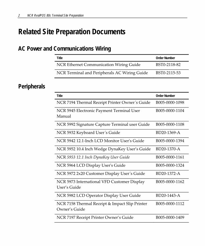
Related Site Preparation Documents
AC Power and Communications Wiring Title Order Number
NCR Ethernet Communication Wiring Guide BST0‐2118‐82
NCR Terminal and Peripherals AC Wiring Guide BST0‐2115‐53
Peripherals Title Order Number
NCR 7194 Thermal Receipt Printer Ownerʹs Guide B005‐0000‐1098
NCR 5945 Electronic Payment Terminal User Manual
B005‐0000‐1104
NCR 5992 Signature Capture Terminal user Guide B005‐0000‐1108
NCR 5932 Keyboard Userʹs Guide BD20‐1369‐A
NCR 5942 12.1‐Inch LCD Monitor Userʹs Guide B005‐0000‐1394
NCR 5952 10.4 Inch Wedge DynaKey User’s Guide BD20‐1370‐A
NCR 5953 12.1 Inch DynaKey User Guide B005‐0000‐1161
NCR 5964 LCD Display Userʹs Guide B005‐0000‐1324
NCR 5972 2x20 Customer Display Userʹs Guide BD20‐1372‐A
NCR 5973 International VFD Customer Display User’s Guide
B005‐0000‐1162
NCR 5982 LCD Operator Display User Guide BD20‐1443‐A
NCR 7158 Thermal Receipt & Impact Slip Printer Owner’s Guide
B005‐0000‐1112
NCR 7197 Receipt Printer Owner’s Guide B005‐0000‐1409
NCR RealPOS 80c Terminal Site Preparation 3
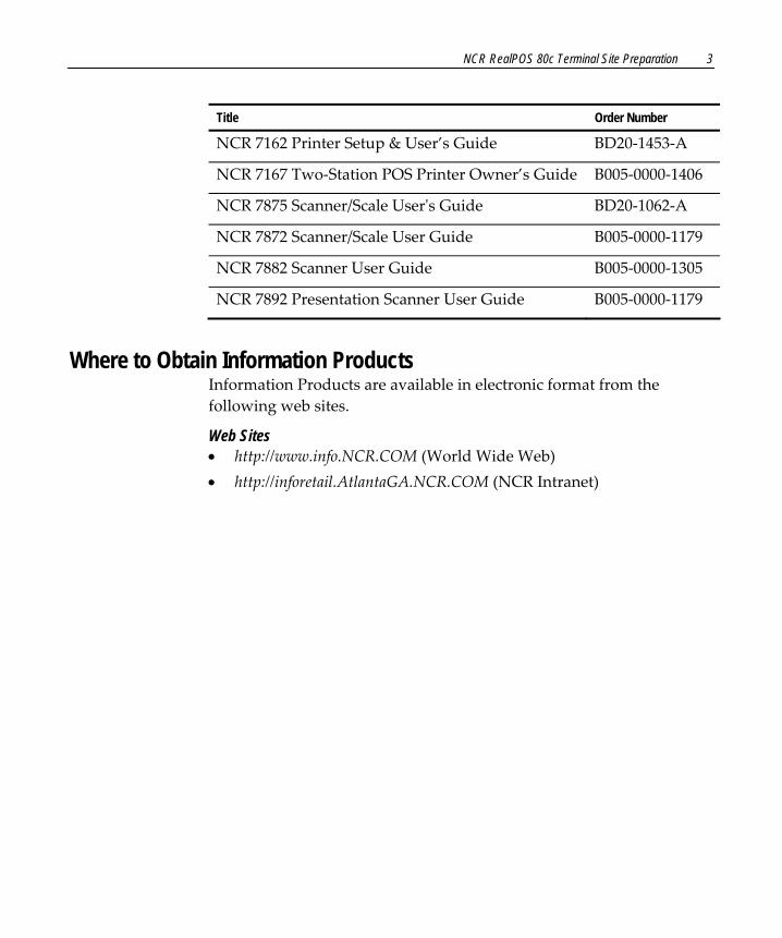
Title Order Number
NCR 7162 Printer Setup & User’s Guide BD20‐1453‐A
NCR 7167 Two‐Station POS Printer Owner’s Guide B005‐0000‐1406
NCR 7875 Scanner/Scale Userʹs Guide BD20‐1062‐A
NCR 7872 Scanner/Scale User Guide B005‐0000‐1179
NCR 7882 Scanner User Guide B005‐0000‐1305
NCR 7892 Presentation Scanner User Guide B005‐0000‐1179
Where to Obtain Information Products
Information Products are available in electronic format from the following web sites.
Web Sites • http://www.info.NCR.COM (World Wide Web) • http://inforetail.AtlantaGA.NCR.COM (NCR Intranet)

4 NCR RealPOS 80c Terminal Site Preparation
Customer Responsibilities Before the system can be installed, the customer must perform or provide the following:
• When required by NCR, provide the NCR Customer Services representative with appropriate drawings that indicate: • Equipment location • Site wiring (power and communications, paths and lengths) • Location of other equipment that may generate electrical noise,
electromagnetic interference, or heat • Make building alterations necessary to meet wiring and other site
requirements • Provide and install all communications cables, wall jacks, special
connectors, and associated hardware • Provide and install necessary power distribution boxes, conduits,
grounds, lightning protection devices, and associated hardware • Ensure all applicable codes, regulations, and laws (including, but
not limited to, electrical, building, safety, and health) are met • Provide and install auxiliary power or other equipment as required • Provide storage or service areas as required • Meet all system/unit environmental requirements • Provide and install floor coverings and environment systems that
limit or control static electricity build‐up and discharge In general, keep the NCR equipment area free from dust, smoke, lint, and other particles. Restrict smoking, eating, and drinking around the equipment. Avoid locating the equipment near other machines that generate ink, carbon, and paper dust particles.
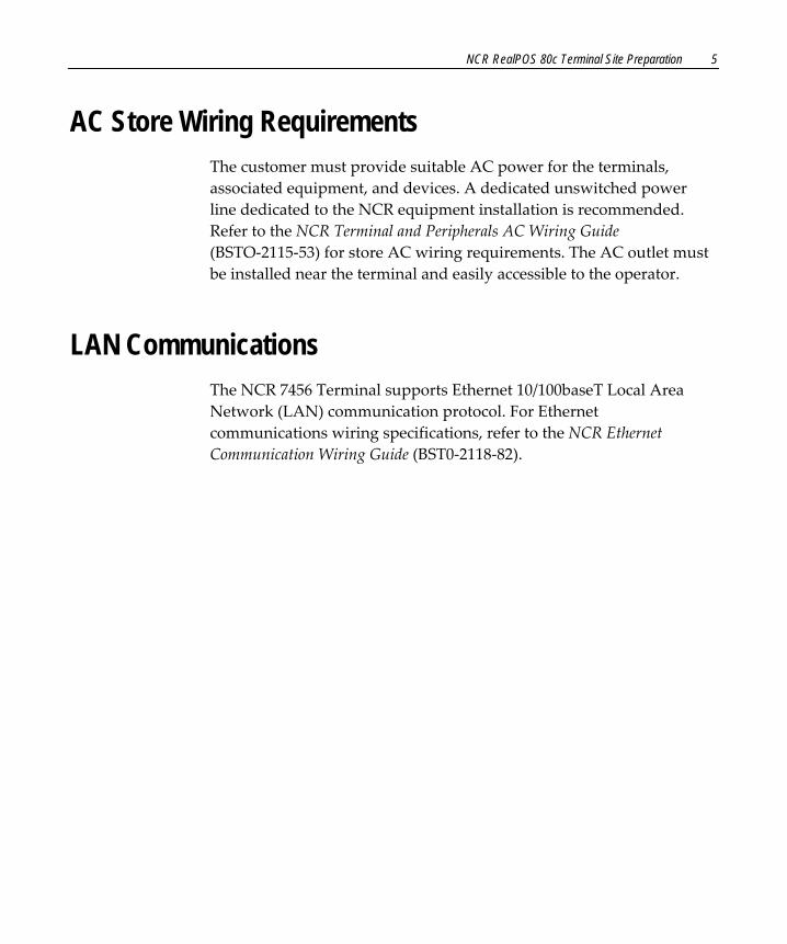
NCR RealPOS 80c Terminal Site Preparation 5
AC Store Wiring Requirements The customer must provide suitable AC power for the terminals, associated equipment, and devices. A dedicated unswitched power line dedicated to the NCR equipment installation is recommended. Refer to the NCR Terminal and Peripherals AC Wiring Guide (BSTO‐2115‐53) for store AC wiring requirements. The AC outlet must be installed near the terminal and easily accessible to the operator.
LAN Communications The NCR 7456 Terminal supports Ethernet 10/100baseT Local Area Network (LAN) communication protocol. For Ethernet communications wiring specifications, refer to the NCR Ethernet Communication Wiring Guide (BST0‐2118‐82).

6 NCR RealPOS 80c Terminal Site Preparation
System Configuration Diagrams
5932 64-Key5932 Big Ticket
2182
2nd Drawer (Y-Cable)
2189
PS/2
19710a
RS-232 Peripherals
5972-1xxx/5973
5972-2xxx
LAN
5952/5953 Dynakey
PS/2 Keyboard
7837 7892
5964Touch Screen
PS/2 Keyboard
7837 7892 CRT
7875
7162
Motherboard
PCI LCD Card
Parallel
DVI VGA AC
7197
7167
5932 USB
USBDaughter
Card
USB(4/6)
Audio OutMic
71977167
RS-232(Powered)
5942
PS/2
Cash Drawer
RS-232RS-232
(Powered)
59925945
7892 7837
RS-232 Peripherals (Powered)
7882
RS-232(Powered)
5982

NCR RealPOS 80c Terminal Site Preparation 7
Handling System Components One person can move terminal system components. However, consider the following when moving the terminal or handling individual components.
• Peripherals do not attach to the base unit and may slide off if the base unit is tipped.
• The keyboard does not attach to the drawer unit and may slide off if the drawer unit is tipped.
• Do not turn the CRTs or customer displays upside down while holding only the display mounting stand. The display is not attached to the stand and may slip out and be damaged if turned upside down.
8 NCR RealPOS 80c Terminal Site Preparation
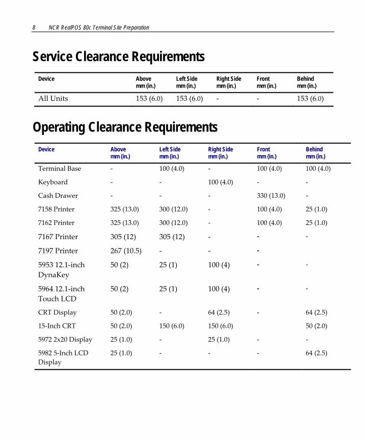
Service Clearance Requirements Device Above
mm (in.) Left Side mm (in.)
Right Side mm (in.)
Front mm (in.)
Behind mm (in.)
All Units 153 (6.0) 153 (6.0) ‐ ‐ 153 (6.0)
Operating Clearance Requirements Device Above
mm (in.) Left Side mm (in.)
Right Side mm (in.)
Front mm (in.)
Behind mm (in.)
Terminal Base ‐ 100 (4.0) ‐ 100 (4.0) 100 (4.0)
Keyboard ‐ ‐ 100 (4.0) ‐ ‐
Cash Drawer ‐ ‐ ‐ 330 (13.0) ‐
7158 Printer 325 (13.0) 300 (12.0) ‐ 100 (4.0) 25 (1.0)
7162 Printer 325 (13.0) 300 (12.0) ‐ 100 (4.0) 25 (1.0)
7167 Printer 305 (12) 305 (12) ‐ ‐ ‐
7197 Printer 267 (10.5) ‐ ‐ ‐
5953 12.1‐inch DynaKey
50 (2) 25 (1) 100 (4) ‐ ‐
5964 12.1‐inch Touch LCD
50 (2) 25 (1) 100 (4) ‐ ‐
CRT Display 50 (2.0) ‐ 64 (2.5) ‐ 64 (2.5)
15‐Inch CRT 50 (2.0) 150 (6.0) 150 (6.0) 50 (2.0)
5972 2x20 Display 25 (1.0) ‐ 25 (1.0) ‐ ‐
5982 5‐Inch LCD Display
25 (1.0) ‐ ‐ ‐ 64 (2.5)
NCR RealPOS 80c Terminal Site Preparation 9
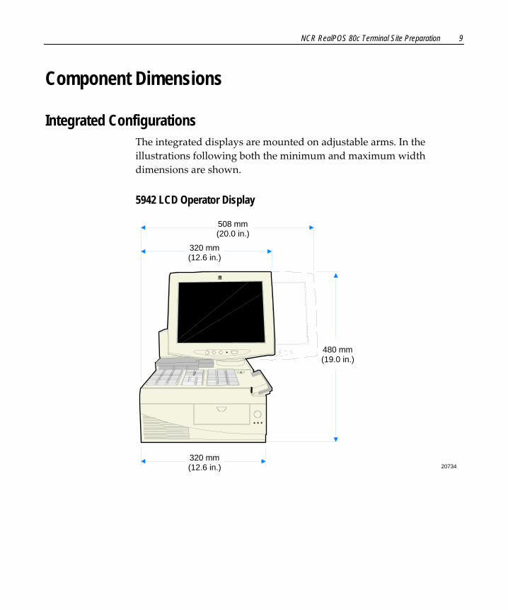
Component Dimensions
Integrated Configurations The integrated displays are mounted on adjustable arms. In the illustrations following both the minimum and maximum width dimensions are shown.
5942 LCD Operator Display
20734
480 mm(19.0 in.)
320 mm(12.6 in.)
320 mm(12.6 in.)
508 mm(20.0 in.)
10 NCR RealPOS 80c Terminal Site Preparation
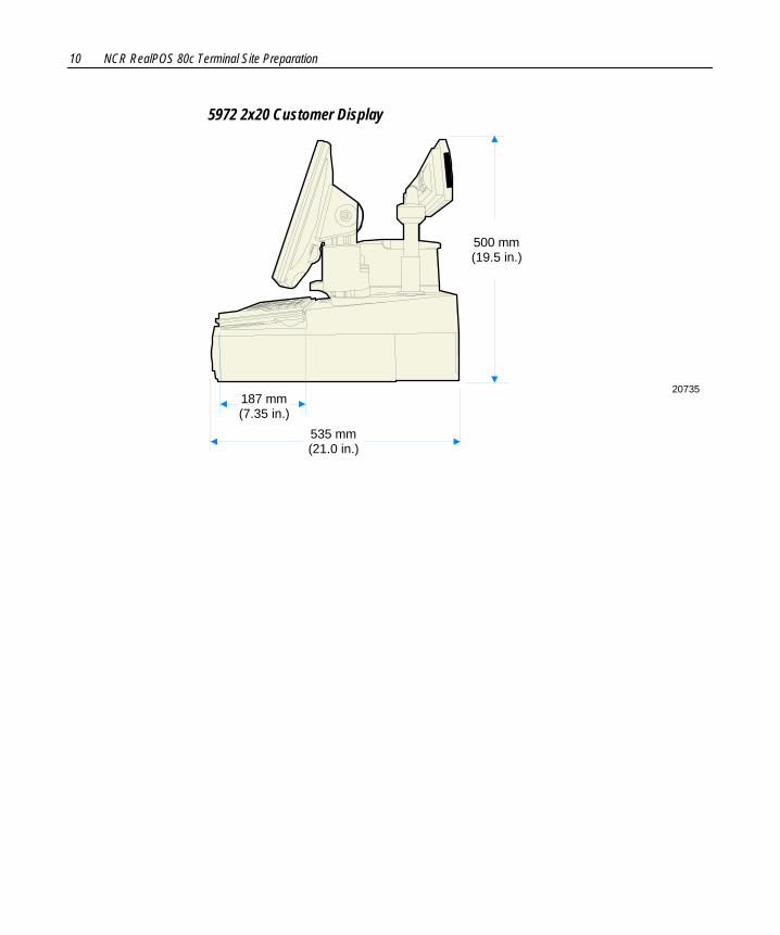
5972 2x20 Customer Display
20735
500 mm(19.5 in.)
535 mm(21.0 in.)
187 mm(7.35 in.)

NCR RealPOS 80c Terminal Site Preparation 11
5953 DynaKey
20732
460 mm(18.25 in.)
320 mm(12.6 in.)
520 mm(20.5 in.)
670 mm(26.25 in.)
12 NCR RealPOS 80c Terminal Site Preparation
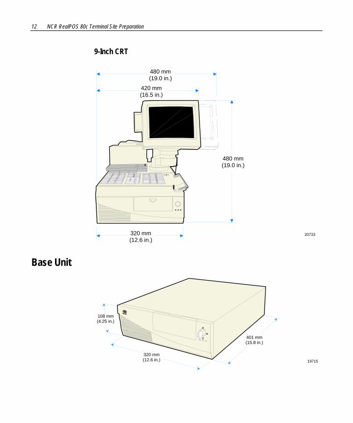
9-Inch CRT
20733
480 mm(19.0 in.)
320 mm(12.6 in.)
420 mm(16.5 in.)
480 mm(19.0 in.)
Base Unit
19715
401 mm(15.8 in.)
320 mm(12.6 in.)
108 mm(4.25 in.)

NCR RealPOS 80c Terminal Site Preparation 13
Cash Drawers
NCR 2182
15413
400 mm(15.75 in.)
108 mm(4.25 in.)
450 mm(17.7 in.)
Operating and Service Clearance for Drawer
254 mm(10.0 in.)
NCR 2189
20434
133 mm(5.25 in.)
527 mm(20.5 in.")
Operating and Service Clearance for Drawer
330 mm(13.0 in.)
464 mm(18.25 in.)

14 NCR RealPOS 80c Terminal Site Preparation
NCR 2183
18038
455 mm(17.9 in.)
108 mm(4.25 in.)
450 mm(17.7 in.)
Operating and Service Clearance for Drawer
263 mm(10.4 in.)
NCR RealPOS 80c Terminal Site Preparation 15
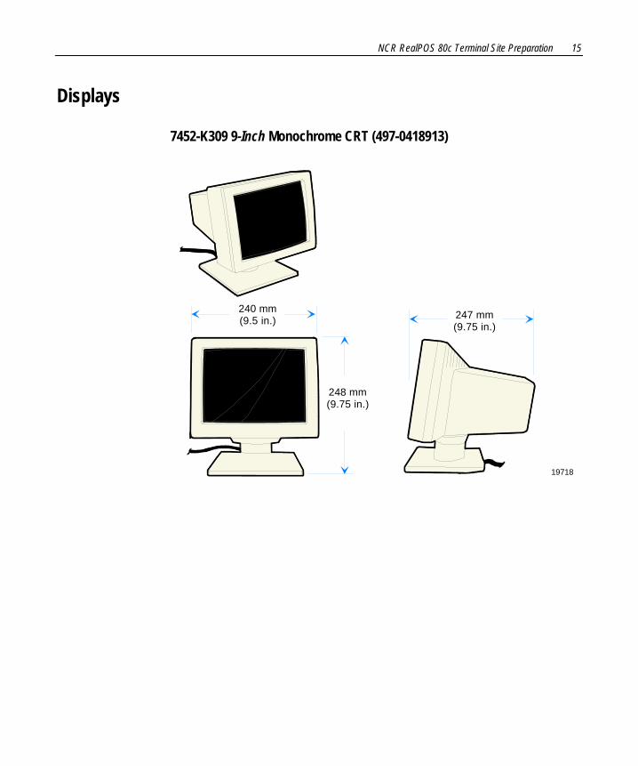
Displays
7452-K309 9-Inch Monochrome CRT (497-0418913)
19718
248 mm(9.75 in.)
240 mm(9.5 in.) 247 mm
(9.75 in.)
16 NCR RealPOS 80c Terminal Site Preparation
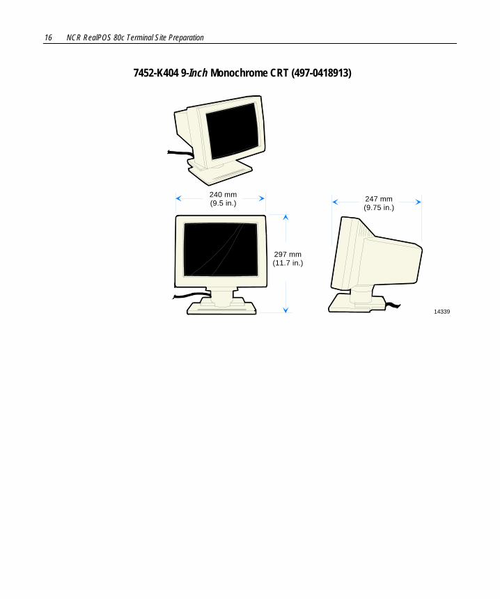
7452-K404 9-Inch Monochrome CRT (497-0418913)
14339
297 mm(11.7 in.)
240 mm(9.5 in.) 247 mm
(9.75 in.)

NCR RealPOS 80c Terminal Site Preparation 17
7452-K419 15-Inch Monochrome CRT (497-0414126)
17386
318 mm(12.5 in.)
361 mm(14.2 in.)
368 mm(14.5 in.)
381 mm(15 in.)

18 NCR RealPOS 80c Terminal Site Preparation
5982 5-Inch Monochrome LCD Operator Display
15411
140 mm(5.5 in.) 112 mm
(4.5 in)
165 mm(6.5 in.)
176 mm(6.9 in.) 16 mm
(0.7 in.)
128 mm(5 in.)
NCR RealPOS 80c Terminal Site Preparation 19
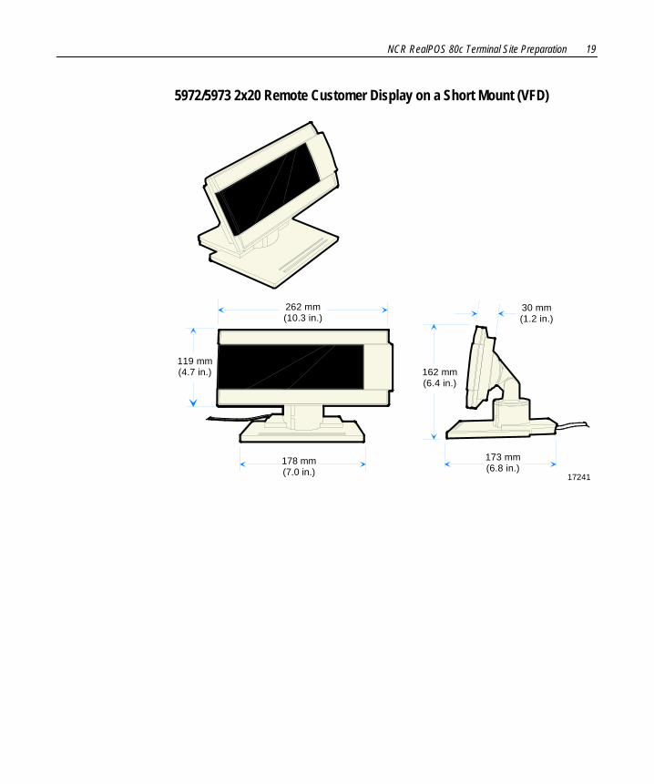
5972/5973 2x20 Remote Customer Display on a Short Mount (VFD)
17241
262 mm(10.3 in.)
162 mm(6.4 in.)
173 mm(6.8 in.)
119 mm(4.7 in.)
30 mm(1.2 in.)
178 mm(7.0 in.)
20 NCR RealPOS 80c Terminal Site Preparation
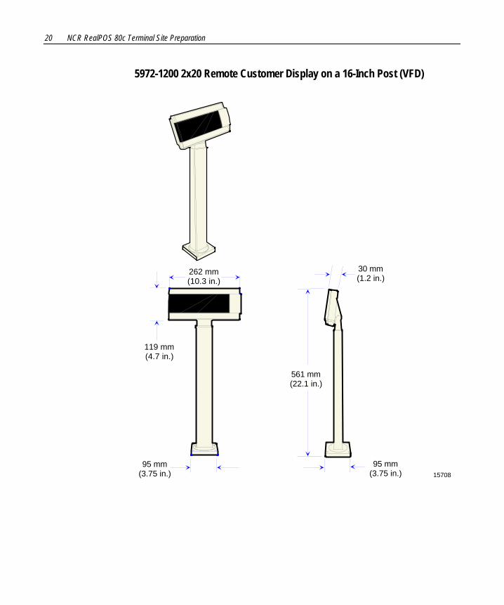
5972-1200 2x20 Remote Customer Display on a 16-Inch Post (VFD)
262 mm(10.3 in.)
1570895 mm
(3.75 in.)
561 mm(22.1 in.)
30 mm(1.2 in.)
119 mm(4.7 in.)
95 mm(3.75 in.)

NCR RealPOS 80c Terminal Site Preparation 21
5972-1200 2x20 Remote Customer Display on a 8-Inch Post (VFD)
20131a
95 mm(3.75 in.)
356 mm(14.1 in.)
262 mm(10.3 in.)
119 mm(4.7 in.)
356 mm(14.1 in.)
30 mm(1.2 in.)
95 mm(3.75 in.)
22 NCR RealPOS 80c Terminal Site Preparation
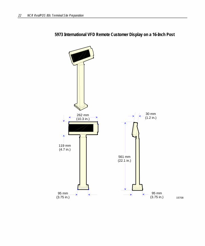
5973 International VFD Remote Customer Display on a 16-Inch Post
262 mm(10.3 in.)
1570895 mm
(3.75 in.)
561 mm(22.1 in.)
30 mm(1.2 in.)
119 mm(4.7 in.)
95 mm(3.75 in.)

NCR RealPOS 80c Terminal Site Preparation 23
5973 International VFD Remote Customer Display on a 8-Inch Post
20131a
95 mm(3.75 in.)
356 mm(14.1 in.)
262 mm(10.3 in.)
119 mm(4.7 in.)
356 mm(14.1 in.)
30 mm(1.2 in.)
95 mm(3.75 in.)
24 NCR RealPOS 80c Terminal Site Preparation
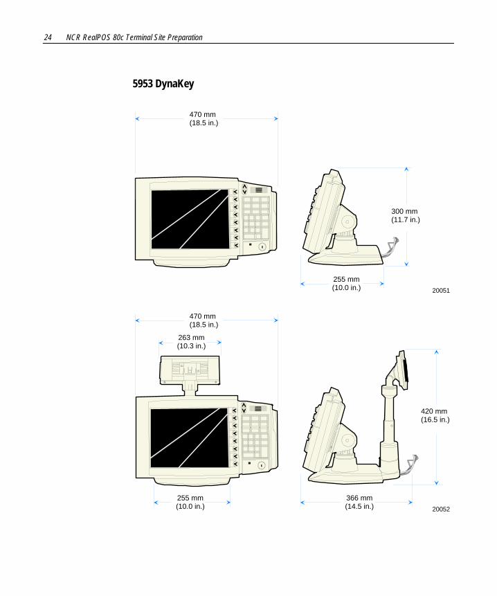
5953 DynaKey
20051
470 mm(18.5 in.)
300 mm(11.7 in.)
255 mm(10.0 in.)
20052
470 mm(18.5 in.)
420 mm(16.5 in.)
366 mm(14.5 in.)
255 mm(10.0 in.)
263 mm(10.3 in.)

NCR RealPOS 80c Terminal Site Preparation 25
5953-K023 Table-Top Mount The Table‐Top Mount is fully adjustable between the minimum and maximum dimensions that are illustrated below. The DynaKey can also be rotated right and left of center (shown) by approximately 90 degrees, as well as tilted from a vertical position to approximately 45 degrees (shown).
19909
213 mm(8.4 in.)
216 mm(8.5 in.)
400 mm(15.75 in.)
330 mm(13.0 in.)
370 mm(14.5 in.)
480 mm(19.0 in.)
38 mm1.5 in.
7.6.mm0.30 in.
70 mm2.75 in.
89 mm3.5 in.
114 mm4.25 in.

26 NCR RealPOS 80c Terminal Site Preparation
There are two positions to install the post to the back of the DynaKey.
19908
270 mm(10.75 in.)
200 mm(8.0 in.)
105 mm4.13 in.
140 mm5.5 in.

NCR RealPOS 80c Terminal Site Preparation 27
5964 12.1-Inch Touch LCD
19555
(348 mm)13.7 in.
(252 mm)9.9 in.
(297 mm)11.7 in.
Tilt/Swivel Dimensions
20305
Swivel Angle88.0
Swivel Angle88.0
Hinge Tilt Angle87.6
28 NCR RealPOS 80c Terminal Site Preparation
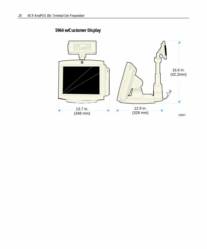
5964 w/Customer Display
19557
12.9 in.(328 mm)
13.7 in.(348 mm)
16.6 in.(42.2mm)
NCR RealPOS 80c Terminal Site Preparation 29
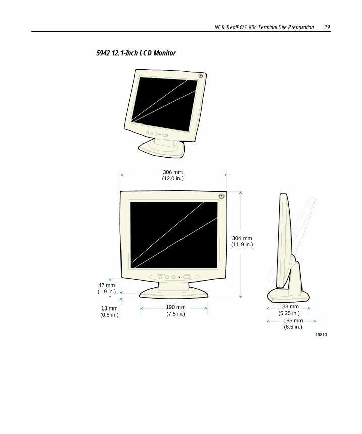
5942 12.1-Inch LCD Monitor
19810
306 mm(12.0 in.)
304 mm(11.9 in.)
190 mm(7.5 in.)
133 mm(5.25 in.)
165 mm(6.5 in.)
47 mm(1.9 in.)
13 mm(0.5 in.)
30 NCR RealPOS 80c Terminal Site Preparation
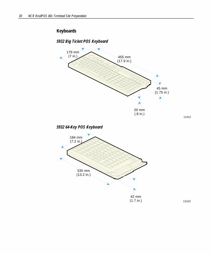
Keyboards
5932 Big Ticket POS Keyboard
11412
179 mm(7 in.)
20 mm(.8 in.)
455 mm(17.9 in.)
45 mm(1.75 in.)
5932 64-Key POS Keyboard
11413
184 mm(7.2 in.)
335 mm(13.2 in.)
42 mm(1.7 in.)
NCR RealPOS 80c Terminal Site Preparation 31
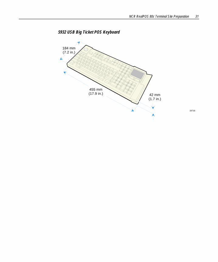
5932 USB Big Ticket POS Keyboard
19716
184 mm(7.2 in.)
455 mm(17.9 in.) 42 mm
(1.7 in.)
32 NCR RealPOS 80c Terminal Site Preparation
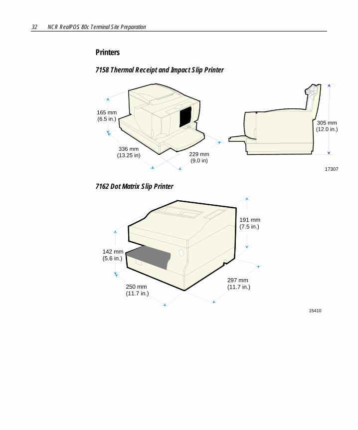
Printers
7158 Thermal Receipt and Impact Slip Printer
305 mm(12.0 in.)
165 mm(6.5 in.)
336 mm(13.25 in) 229 mm
(9.0 in)17307
7162 Dot Matrix Slip Printer
15410
250 mm(11.7 in.)
297 mm(11.7 in.)
191 mm(7.5 in.)
142 mm(5.6 in.)
NCR RealPOS 80c Terminal Site Preparation 33
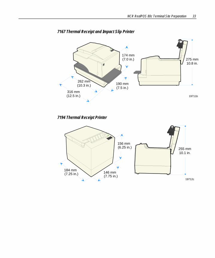
7167 Thermal Receipt and Impact Slip Printer
19711b
190 mm(7.5 in.)
174 mm(7.0 in.)
262 mm(10.3 in.)
316 mm(12.5 in.)
275 mm10.8 in.
7194 Thermal Receipt Printer
19712c
146 mm(7.75 in.)
156 mm(6.25 in.)
184 mm(7.25 in.)
255 mm10.1 in.
34 NCR RealPOS 80c Terminal Site Preparation
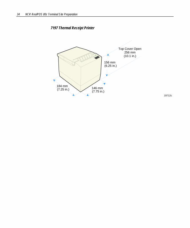
7197 Thermal Receipt Printer
19712c
146 mm(7.75 in.)
156 mm(6.25 in.)
184 mm(7.25 in.)
Top Cover Open256 mm(10.1 in.)
NCR RealPOS 80c Terminal Site Preparation 35
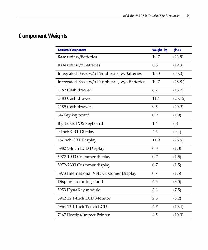
Component Weights
Terminal Component Weight kg (lbs.)
Base unit w/Batteries 10.7 (23.5)
Base unit w/o Batteries 8.8 (19.3)
Integrated Base; w/o Peripherals, w/Batteries 13.0 (35.0)
Integrated Base; w/o Peripherals, w/o Batteries 10.7 (28.8.)
2182 Cash drawer 6.2 (13.7)
2183 Cash drawer 11.4 (25.15)
2189 Cash drawer 9.5 (20.9)
64‐Key keyboard 0.9 (1.9)
Big ticket POS keyboard 1.4 (3)
9‐Inch CRT Display 4.3 (9.4)
15‐Inch CRT Display 11.9 (26.5)
5982 5‐Inch LCD Display 0.8 (1.8)
5972‐1000 Customer display 0.7 (1.5)
5972‐2300 Customer display 0.7 (1.5)
5973 International VFD Customer Display 0.7 (1.5)
Display mounting stand 4.3 (9.5)
5953 DynaKey module 3.4 (7.5)
5942 12.1‐Inch LCD Monitor 2.8 (6.2)
5964 12.1‐Inch Touch LCD 4.7 (10.4)
7167 Receipt/Impact Printer 4.5 (10.0)
36 NCR RealPOS 80c Terminal Site Preparation
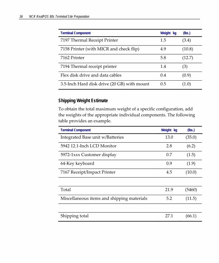
Terminal Component Weight kg (lbs.)
7197 Thermal Receipt Printer 1.5 (3.4)
7158 Printer (with MICR and check flip) 4.9 (10.8)
7162 Printer 5.8 (12.7)
7194 Thermal receipt printer 1.4 (3)
Flex disk drive and data cables 0.4 (0.9)
3.5‐Inch Hard disk drive (20 GB) with mount 0.5 (1.0)
Shipping Weight Estimate To obtain the total maximum weight of a specific configuration, add the weights of the appropriate individual components. The following table provides an example.
Terminal Component Weight kg (lbs.)
Integrated Base unit w/Batteries 13.0 (35.0)
5942 12.1‐Inch LCD Monitor 2.8 (6.2)
5972‐1xxx Customer display 0.7 (1.5)
64‐Key keyboard 0.9 (1.9)
7167 Receipt/Impact Printer 4.5 (10.0)
Total 21.9 (5460)
Miscellaneous items and shipping materials 5.2 (11.5)
Shipping total 27.1 (66.1)
NCR RealPOS 80c Terminal Site Preparation 37
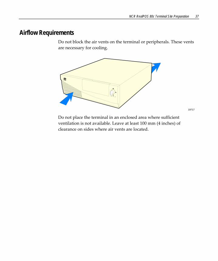
Airflow Requirements Do not block the air vents on the terminal or peripherals. These vents are necessary for cooling.
19717 Do not place the terminal in an enclosed area where sufficient ventilation is not available. Leave at least 100 mm (4 inches) of clearance on sides where air vents are located.

38 NCR RealPOS 80c Terminal Site Preparation
Electrical Requirements The terminalʹs power cord plugs into the back of the terminal and into a three‐wire, single‐phase, 120 or 240 VAC receptacle. The available power cords are described in the System Cables section.
The terminalʹs internal power supply has a maximum output of 237 Watts and provides power to the terminal, one printer, and peripherals. Additionally, an AC power socket is available on the back of the terminal for a CRT.
Maximum Terminal Power Usage
120 Volt System 240 Volt System
Voltage Range 90 ‐ 136 VAC 180 ‐ 265 VAC
Frequency 50/60 Hz 50/60 Hz
Current 4.6 Amps 2.3 Amps
Peripheral Power Requirements The number of peripherals that the terminal can support is dependent upon which peripherals are connected. For planning purposes, use the RealPOS 80c Power Matrix (B005‐0000‐1526) to calculate the power requirements for your specific system configuration.
Note: This file requires Microsoft Excel to run.
NCR RealPOS 80c Terminal Site Preparation 39
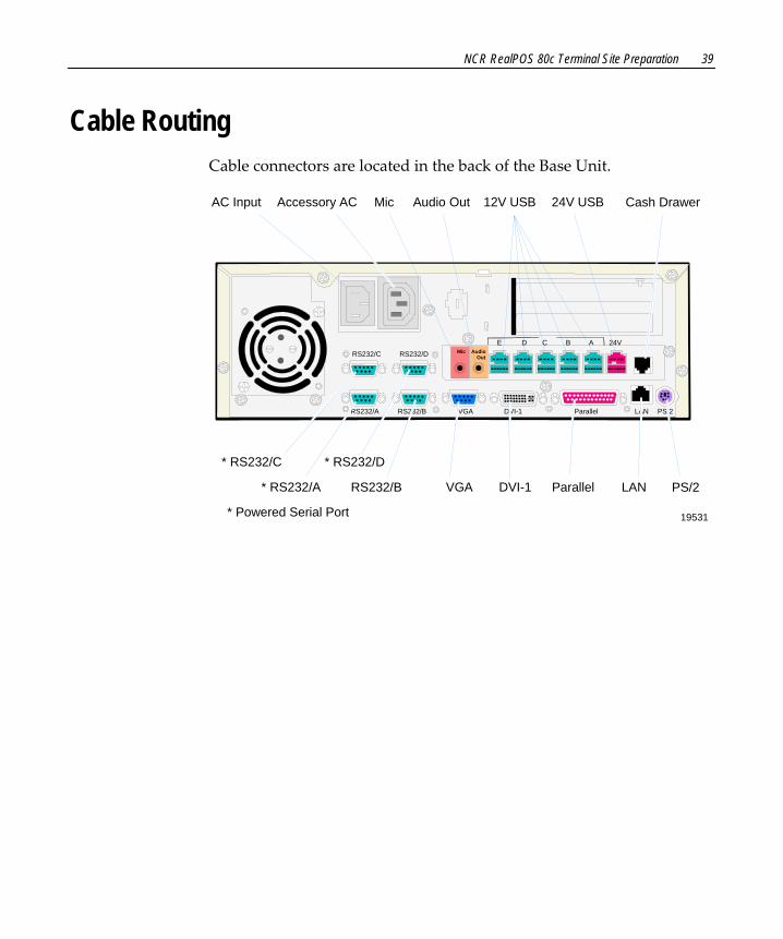
Cable Routing Cable connectors are located in the back of the Base Unit.
Mic Audio Out
E D C B A 24VRS232/C RS232/D
RS232/A RS232/B VGA DVI-1 Parallel LAN PS/2
19531
* RS232/A RS232/B
* RS232/C * RS232/D
VGA DVI-1 Parallel LAN PS/2
12V USB 24V USB Cash DrawerAC Input Accessory AC Mic Audio Out
* Powered Serial Port

40 NCR RealPOS 80c Terminal Site Preparation
System Cables
Printer Cables Powered USB
USB (Printer)24V USB+(Terminal)Power (Printer)
19307
Access Hole Diameters
497-0424888 - 1 m(1416-C713-0010)
497-0424501 - 4 m(1416-C713-0040)
23.0 mm(0.9 in.)
19.0 mm(0.75 in.)
Powered USB (Power Only)
19721
24V USB+(Terminal)
Power(Printer)
497-0424887 - 1m1416-C712-0010
497-0422292 - 4m1416-C712-0040
Access Hole Diameters 23.0 mm(0.9 in.)
19.0 mm(0.75 in.)

NCR RealPOS 80c Terminal Site Preparation 41
RS-232 (9-Pin to 9-Pin)
19722
9-pinD-shell
Receptacle
9-pinD-shell
Receptacle
497-0408349 - 0.7 m(1416-C359-0007)
497-0407943 - 4 m(1416-C266-0040)
RS-232(Printer)
RS-232(Terminal)
Access Hole Diameters 38.0 mm(1.5 in.)
38.0 mm(1.5 in.)
RS-232 (9-Pin to 25-Pin)
20127a
9-pinD-shell
Receptacle
25-pinD-shell
Plug
497-0407427 - 1.0 m(1416-C337-0010)
497-0407429 - 4 m(1416-C337-0040)
RS-232(Printer)
RS-232(Terminal)
63.5 mm(2.5 in.)
Access Hole Diameters38 mm(1.5 in.)

42 NCR RealPOS 80c Terminal Site Preparation
Scanner Cables
7872 or 7875 Scanner/Scale (RS-232)
15479
RS-232(Scanner)
D-Shell9-Pin
Receptacle
Modular10-PinPlug
497-0300422 - 4 m(1416-C019-0040)
RS-232(Terminal)
Access Hole Diameters 19.0 mm(0.75 in.)
38.0 mm(1.5 in.)
7892 Scanner (Powered RS-232)
20450
Scanner
D-Shell9-Pin
Receptacle
Modular10-PinPlug
497-0425593 - 3.0 m(1416-C643-0030)
RS-232(Terminal)
Access Hole Diameters 32.0 mm(1.25 in.)
38.0 mm(1.5 in.)
NCR RealPOS 80c Terminal Site Preparation 43
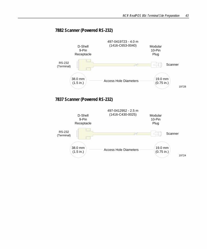
7882 Scanner (Powered RS-232)
19728
Scanner
D-Shell9-Pin
Receptacle
Modular10-PinPlug
497-0419723 - 4.0 m(1416-C653-0040)
RS-232(Terminal)
Access Hole Diameters 19.0 mm(0.75 in.)
38.0 mm(1.5 in.)
7837 Scanner (Powered RS-232)
19724
Scanner
D-Shell9-Pin
Receptacle
Modular10-PinPlug
497-0412952 - 2.5 m(1416-C430-0025)
RS-232(Terminal)
Access Hole Diameters 19.0 mm(0.75 in.)
38.0 mm(1.5 in.)
44 NCR RealPOS 80c Terminal Site Preparation
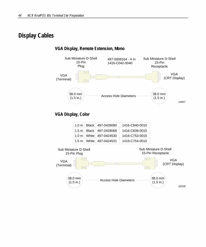
Display Cables
VGA Display, Remote Extension, Mono
14607
VGA(CRT Display)
Sub Miniature D-Shell15-PinPlug
497-0008164 - 4 m1416-C042-0040
Sub Miniature D-Shell15-Pin
Receptacle
VGA(Terminal)
Access Hole Diameters 38.0 mm(1.5 in.)
38.0 mm(1.5 in.)
VGA Display, Color
16318
VGA(CRT Display)
VGA(Terminal)
Access Hole Diameters 38.0 mm(1.5 in.)
38.0 mm(1.5 in.)
Sub Miniature D-Shell15-Pin Plug
Sub Miniature D-Shell15-Pin Receptacle
497-0428080 1416-C840-00101.0 m Black1.5 m Black1.0 m
White1.5 mWhite
497-0428068 1416-C839-0015497-0424530 1416-C753-0015497-0424531 1416-C754-0010
NCR RealPOS 80c Terminal Site Preparation 45
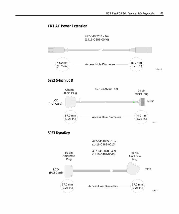
CRT AC Power Extension
19741
497-0406237 - 4m(1416-C508-0040)
Access Hole Diameters 45.0 mm(1.75 in.)
45.0 mm(1.75 in.)
5982 5-Inch LCD
19731
LCD(PCI Card)
5982
497-0409750 - 4mChamp50-pin Plug
24-pinMinifit Plug
Access Hole Diameters 44.0 mm(1.75 in.)
57.0 mm(2.25 in.)
5953 DynaKey
19847
5953
50-pinAmplimite
Plug
50-pinAmplimite
Plug
497-0414885 - 1 m(1416-C482-0010)
497-0413878 - 4 m(1416-C482-0040)
LCD(PCI Card)
Access Hole Diameters 57.0 mm(2.25 in.)
57.0 mm(2.25 in.)
46 NCR RealPOS 80c Terminal Site Preparation
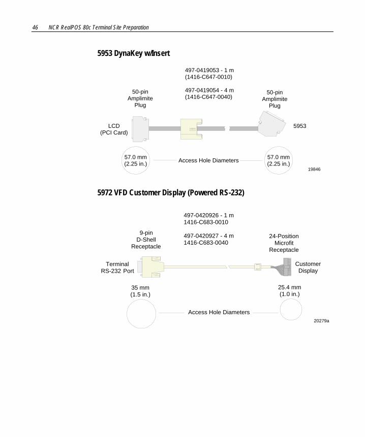
5953 DynaKey w/Insert
19846
5953
50-pinAmplimite
Plug
50-pinAmplimite
Plug
LCD(PCI Card)
497-0419053 - 1 m(1416-C647-0010)
497-0419054 - 4 m(1416-C647-0040)
Access Hole Diameters 57.0 mm(2.25 in.)
57.0 mm(2.25 in.)
5972 VFD Customer Display (Powered RS-232)
20279a
CustomerDisplay
TerminalRS-232 Port
497-0420926 - 1 m1416-C683-0010
497-0420927 - 4 m1416-C683-0040
9-pinD-Shell
Receptacle
24-PositionMicrofit
Receptacle
25.4 mm(1.0 in.)
Access Hole Diameters
35 mm(1.5 in.)
NCR RealPOS 80c Terminal Site Preparation 47
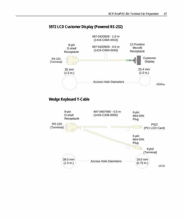
5972 LCD Customer Display (Powered RS-232)
20281a
9-pinD-shell
Receptacle
12-PositionMicrofit
Receptacle
CustomerDisplay
RS-232(Terminal)
497-0420928 - 1.0 m(1416-C684-0010)
497-0420929 - 4.0 m(1416-C684-0040)
25.4 mm(1.0 in.)
Access Hole Diameters
35 mm(1.5 in.)
Wedge Keyboard Y-Cable
19733
497-0407490 - 0.5 m(1416-C338-0005)
RS-232(Terminal)
Kybd(Terminal)
6-pinMini-DINPlug
5-pinMini-DINPlug
9-pinD-shellReceptacle
PS/2(PCI LCD Card)
Access Hole Diameters 19.0 mm(0.75 in.)
38.0 mm(1.5 in.)
48 NCR RealPOS 80c Terminal Site Preparation
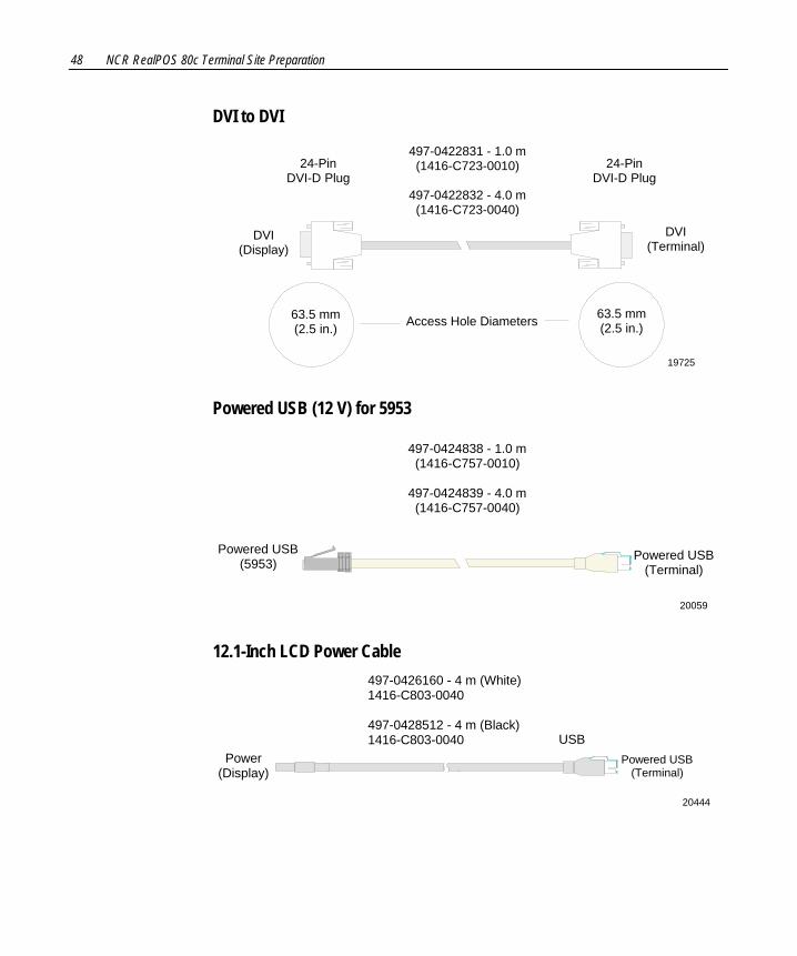
DVI to DVI
19725
63.5 mm(2.5 in.)Access Hole Diameters
497-0422831 - 1.0 m(1416-C723-0010)
497-0422832 - 4.0 m(1416-C723-0040)
63.5 mm(2.5 in.)
24-PinDVI-D Plug
24-PinDVI-D Plug
DVI(Terminal)
DVI(Display)
Powered USB (12 V) for 5953
20059
497-0424838 - 1.0 m(1416-C757-0010)
497-0424839 - 4.0 m(1416-C757-0040)
Powered USB(5953)
Powered USB(Terminal)
12.1-Inch LCD Power Cable
20444
Power(Display)
497-0426160 - 4 m (White)1416-C803-0040
497-0428512 - 4 m (Black)1416-C803-0040 USB
Powered USB(Terminal)
NCR RealPOS 80c Terminal Site Preparation 49
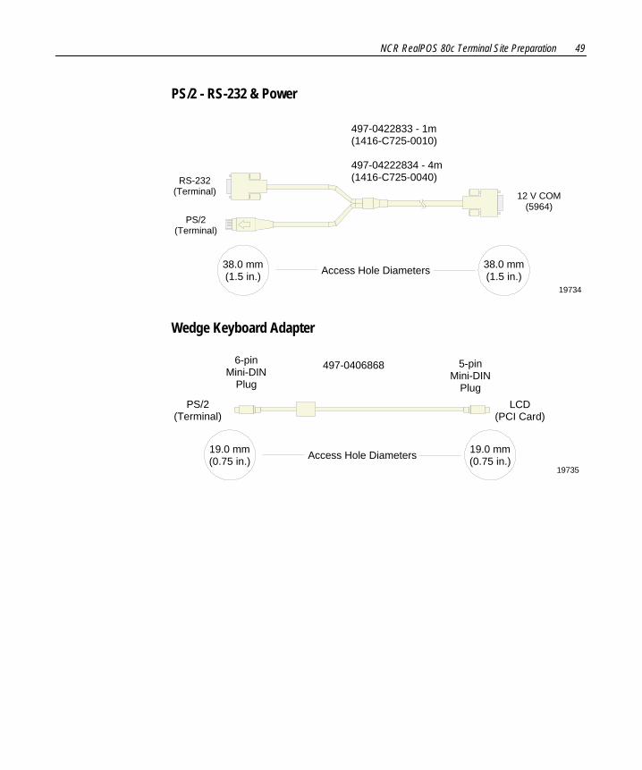
PS/2 - RS-232 & Power
497-0422833 - 1m(1416-C725-0010)
497-04222834 - 4m(1416-C725-0040)
19734
RS-232(Terminal)
PS/2(Terminal)
12 V COM(5964)
Access Hole Diameters 38.0 mm(1.5 in.)
38.0 mm(1.5 in.)
Wedge Keyboard Adapter
19735
497-0406868
PS/2(Terminal)
6-pinMini-DIN
Plug
5-pinMini-DIN
PlugLCD
(PCI Card)
Access Hole Diameters 19.0 mm(0.75 in.)
19.0 mm(0.75 in.)
50 NCR RealPOS 80c Terminal Site Preparation
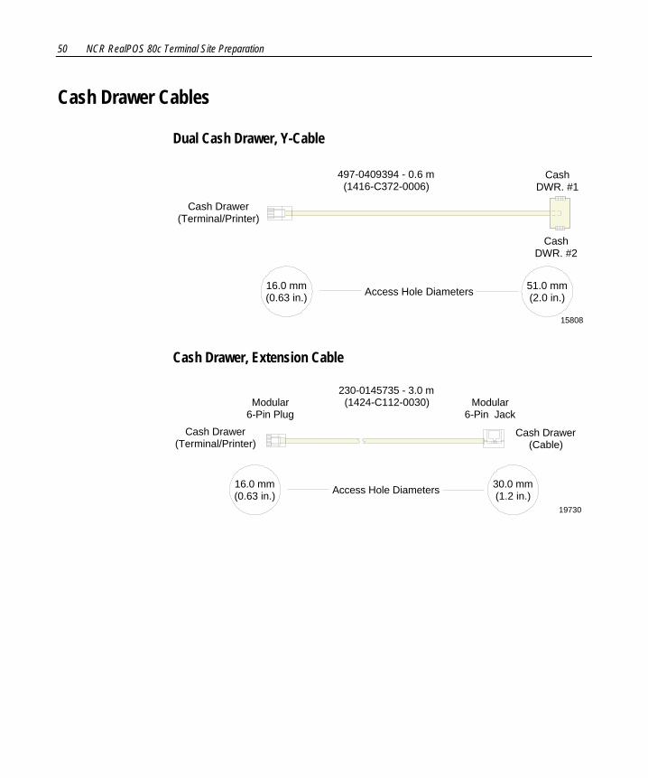
Cash Drawer Cables
Dual Cash Drawer, Y-Cable
15808
497-0409394 - 0.6 m(1416-C372-0006)
CashDWR. #1
CashDWR. #2
Cash Drawer(Terminal/Printer)
Access Hole Diameters 51.0 mm(2.0 in.)
16.0 mm(0.63 in.)
Cash Drawer, Extension Cable
19730
230-0145735 - 3.0 m(1424-C112-0030)
Cash Drawer(Terminal/Printer)
Cash Drawer(Cable)
Modular6-Pin Jack
Modular 6-Pin Plug
Access Hole Diameters 30.0 mm(1.2 in.)
16.0 mm(0.63 in.)

NCR RealPOS 80c Terminal Site Preparation 51
Communications Cable
Ethernet, 10/100BaseT
16298
Modular8-PinPlug
Modular8-PinPlug
497-0008905 - 3.0 m(1416-C059-0030)
Access Hole Diameters 19.0 mm(0.75 in.)
19.0 mm(0.75 in.)
Keyboard Cables
PS/2 Keyboard Extension
15403
PS/2(Keyboard)
PS/2(Terminal)
6-pinMini-DIN
Plug
6-pinMini-DIN
Receptacle
497-0406056 - 1.8 m(1416-C281-0018)
Access Hole Diameters 19.0 mm(0.75 in.)
19.0 mm(0.75 in.)
52 NCR RealPOS 80c Terminal Site Preparation
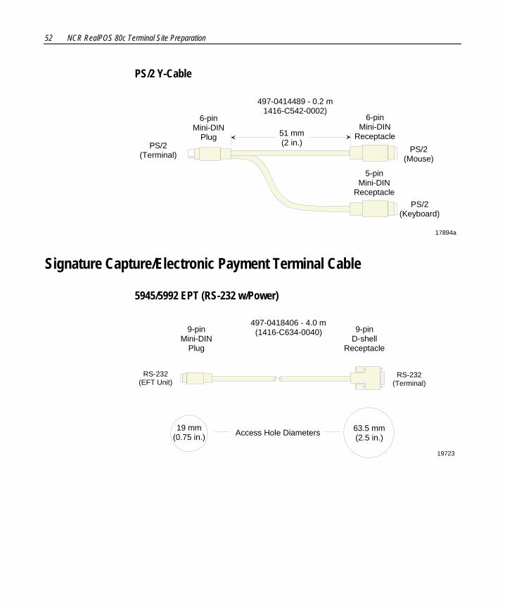
PS/2 Y-Cable
17894a
PS/2(Mouse)
PS/2(Terminal)
6-pinMini-DIN
Plug
6-pinMini-DIN
Receptacle
PS/2(Keyboard)
5-pinMini-DIN
Receptacle
51 mm(2 in.)
497-0414489 - 0.2 m1416-C542-0002)
Signature Capture/Electronic Payment Terminal Cable
5945/5992 EPT (RS-232 w/Power)
19723
63.5 mm(2.5 in.)
19 mm(0.75 in.) Access Hole Diameters
497-0418406 - 4.0 m(1416-C634-0040) 9-pin
D-shellReceptacle
RS-232(EFT Unit)
RS-232(Terminal)
9-pinMini-DIN
Plug

NCR RealPOS 80c Terminal Site Preparation 53
Power Cables
AC Power
15405
45 mm(1.75 in.)Access Hole Diameter
Terminal
006-1009037 - U.S.
The following power cables (not shown)also have an IEC connection of 45 mm: 006-8601001 - Japan Twist-Lock 006-8601010 - International 006-8601011 - SEV 006-8601012 - U.K. 006-8601019 - Australia

54 NCR RealPOS 80c Terminal Site Preparation
Environmental Requirements Barometric Pressure
The terminal operates within the following barometric pressure conditions:
• Maximum operating altitude: 3,000 m (9,843 ft.) • Operating range of pressure: 105 to 69 kPa (15.2 to 10.0 lb./in.)
Temperature The terminal operates over the temperature ranges shown below. Continuous operation must be avoided at or near the indicated temperature extremes or in locations where the temperature changes beyond the restrictions.
Temperature Parameter Restriction
Operating 5°C to 45°C (41°F to 113°F), dry bulb
Storage ‐10°C to 50°C (14°F to 122°F), three months
Shipping ‐40°C to 60°C (‐40°F to 140°F), one week
Dew Point 26°C (79°F) maximum
Humidity The terminal operates within the humidity ranges shown below. Continuous operation must be avoided at or near the indicated humidity extremes or in locations where the humidity changes beyond the restrictions. Never expose the terminal to condensation.
Humidity Type Restriction
Relative 10% to 90%
Maximum change rate 10%/60 minutes
Storage 10% to 90% relative humidity, three months
Shipping 5% to 95% relative humidity, one week
Appendix A: Transient Protection
AC Power Line Transient Protection
In the process of power distribution, transient electrical energy (including, but not limited to, lightning strikes, intermittent short circuits, and switching transients) can be introduced onto power lines. Such transient energy can be very damaging to electronic hardware, and can also cause data corruption. Under these circumstances, NCR recommends the use of AC power transient suppressors. Such protection devices are intended to guard against power line transients that can result in hardware damage and various system or program errors.
Improvement of any deficiencies in power quality is a customer responsibility. Malfunction and/or component failure as a result of power quality problems are/is not covered by the NCR Maintenance Agreement. NCR accepts no liability for any such occurrence nor for its consequences.
When power transient suppression is required, the suppressors used should meet the following minimum requirements:
• Dissipate energy to match the appropriate application categories as defined by IEEE Standard 587.
• Be of the voltage limiting (clipping), or tracking filter type. The suppressor must not clamp the voltage to zero, and must self‐recover after the passage of the transient. The suppressor may be of the hybrid type construction that makes use of various technologies in order to meet speed and dissipation requirements.

A-2 Appendix A: Transient Protection
• Upon failure, exhibit a positive indication of its failure such as a blown fuse or tripped breaker.
• Be listed by the accepted safety organization for the country involved (UL, CSA, VDE, ETL, and so on) and the installation must conform to local, state, and national electrical codes and regulations.
Data Line Transient Protection The nature of the transient phenomenon may extend to the data communication lines connected to this equipment. It is the responsibility of the customer to install and connect a data line transient suppression system to correct or prevent any deficiencies. Such systems must meet the following minimum requirements:
• Be of the voltage limiting type and must self‐recover after passage of the transient.
• Insert less than 5 ohms resistance and minimal inductive and capacitive loading at the operating frequency for data lines, in order to avoid signal degradation.
• Be installed in accordance with all applicable local, state, and national electrical codes and regulation.
Note: In certain countries, NCR is able to supply both power and data line transient suppressors as well as a comprehensive line of power conditioning equipment. For application data, contact your NCR Customer Services Division Representative.
Related Documents
![NCR RealPOS 7456 A Presentation to [Customer Name] NCR Confidential [Your Name] [Date]](https://static.cupdf.com/doc/110x72/56649d205503460f949f58d3/ncr-realpos-7456-a-presentation-to-customer-name-ncr-confidential-your-name.jpg)


