7 Design 382 The longitudinal reinforcement due to torsion shall either be distributed evenly over the length of the panels or concentrated at the corners. In the case of combined action of torsion, bending and shear force in a solid section, the core within the idealised hollow cross-section may be used for the transmission of the shear forces. In the case of combined action of torsion, bending and shear force, the internal forces and moments are replaced by a statically equivalent set of normal and shear forces. The reinforcement is then determined according to the provisions of sub-clauses 7.3.2 and 7.3.3. For box-girder sections the maximum resistance of a panel is given by V Rd,c for members without and V Rd,max for members with shear reinforcement, respectively. For other sections (such as rectangular cross-sections) the maximum resistance has to be checked by 1 2 max , 2 max , Rd Ed Rd Ed V V T T (7.3-55) where T Rd,max is calculated as: cos sin 2 max , k ef c ck c Rd A t f k T (7.3-56) and the definitions are given in sub-clauses 7.3.2 and 7.3.3. 7.3.5 Punching 7.3.5.1 General Punching failures may develop with limited deformations (brittle behaviour). Therefore, the effects of imposed deformations (temperature, creep and shrinkage, settlements, etc.) should be taken into account in design. The influence of imposed deformations can however be neglected if sufficient deformation capacity is provided. Strategies for increasing the deformation capacity are: – choice of a sufficiently large supported area and depth of slab in combination with low bending reinforcement ratios (rul es are given in sub-clause 7.3.5.3) Punching can result from a concentrated load applied on a relatively small area of the structure. In flat slabs, punching shear failures normally develop around supported areas (columns, capitals, walls). In other cases (as for instance foundation slabs, transfer slabs, deck slabs of bridges) punching failures can also develop around loaded areas. The rules presented hereafter for flat slabs apply by analogy to loaded areas. This final draft of the fib MC2010 has not been published; it is intended only for the purpose of voting by the General Assembly.

Welcome message from author
This document is posted to help you gain knowledge. Please leave a comment to let me know what you think about it! Share it to your friends and learn new things together.
Transcript
7 Design 382
The longitudinal reinforcement due to torsion shall either be distributed evenly over the length of the panels or concentrated at the corners.
In the case of combined action of torsion, bending and shear force in a solid section, the core within the idealised hollow cross-section may be used for the transmission of the shear forces.
In the case of combined action of torsion, bending and shear force, the internal forces and moments are replaced by a statically equivalent set of normal and shear forces. The reinforcement is then determined according to the provisions of sub-clauses 7.3.2 and 7.3.3.
For box-girder sections the maximum resistance of a panel is given by VRd,cfor members without and VRd,max for members with shear reinforcement, respectively.
For other sections (such as rectangular cross-sections) the maximum resistance has to be checked by
12
max,
2
max,
����
����
��
��
����
�
Rd
Ed
Rd
Ed
VV
TT (7.3-55)
where TRd,max is calculated as:
�
cossin2max, kefc
ckcRd AtfkT � (7.3-56)
and the definitions are given in sub-clauses 7.3.2 and 7.3.3.
7.3.5 Punching
7.3.5.1 GeneralPunching failures may develop with limited deformations (brittle
behaviour). Therefore, the effects of imposed deformations (temperature, creep and shrinkage, settlements, etc.) should be taken into account in design. The influence of imposed deformations can however be neglected if sufficient deformation capacity is provided. Strategies for increasing the deformation capacity are:
– choice of a sufficiently large supported area and depth of slab in combination with low bending reinforcement ratios (rules are given in sub-clause 7.3.5.3)
Punching can result from a concentrated load applied on a relatively small area of the structure. In flat slabs, punching shear failures normally develop around supported areas (columns, capitals, walls). In other cases (as for instance foundation slabs, transfer slabs, deck slabs of bridges) punching failures can also develop around loaded areas. The rules presented hereafter for flat slabs apply by analogy to loaded areas.
This final draft of the fib MC2010 has not been published; it is intended only for the purpose of voting by the General Assembly.

Model Code 2010, Final draft 383
– use of punching shear reinforcement (rules are given in sub-clause7.3.5.3)
With flat slabs, safety against punching is particularly significant as the failure of one column can propagate to adjacent columns leading to acomplete collapse of a structure. To avoid such progressive collapses, one of the following strategies should be adopted:
– increase of the deformation capacity of the potential failure zones (see above) to allow internal forces to redistribute, and/or
– arrange integrity reinforcement for slabs with limited deformation capacity (rules are given in sub-clause 7.3.5.6)
7.3.5.2 Design shear force, shear-resisting effective depth and control perimeter
(1) Design shear forceThe design shear force with respect to punching (VEd) is calculated as the
sum of design shear forces acting on a basic control perimeter (b1).
(2) Shear-resisting effective depth
Figure 7.3-200:Effective depth of the slab considering support penetration (dv) and effective depth for bending calculations (d).
The shear-resisting effective depth of the slab (dv) is the distance from the centroid of the reinforcement layers to the supported area, see Figure 7.3-20.
(3) Basic control perimeter (b1)For flat slabs and footings, the design shear force is equal to the value of The basic control perimeter b1 may normally be taken at a distance 0.5dv
This final draft of the fib MC2010 has not been published; it is intended only for the purpose of voting by the General Assembly.

7 Design 384
the support reaction reduced by the actions applied inside the basic control perimeter (such as gravity loads, soil pressure at footings and deviation forces of prestressing cables).
Figure 7.3-211: Basic control perimeters around supported areas.
Figure 7.3-222:Basic control perimeter around walls.
from the supported area (Figure 7.3-211 and Figure 7.3-222) and should be determined in order to minimize its length (Figure 7.3-211c). The length of the control perimeter is limited by slab edges (Figure 7.3-211d).
Figure 7.3-233:Choice of the potentially governing control perimeter.
In the case of slabs with variable depth control sections at a greater distance from the supported area may be governing (refer to Figure 7.3-233).
(4) Shear-resisting control perimeter (b0)The shear-resisting control perimeter b0 can be obtained on the basis of a For calculating the punching shear resistance, a shear-resisting control
This final draft of the fib MC2010 has not been published; it is intended only for the purpose of voting by the General Assembly.

Model Code 2010, Final draft 385
detailed shear field analysis as:
d,maxperp
EdVb,
0 � (7.3-57)
where perp,d,max is the maximum shear force per unit length perpendicular to the basic control perimeter (Figure 7.3-244).
Figure 7.3-244:Shear force per unit length (vd) and maximum value perpendicular to the basic control perimeter.
perimeter (b0) is used. The shear-resisting control perimeter accounts for the non-uniform distribution of shear forces along the basic control perimeter.
Figure 7.3-255 Reduction of basic control perimeter for large supported areas (b1,red).
A non-uniform distribution of the shear forces may result due to:1. Concentrations of the shear forces at the corners of large supported
areas. This effect can approximately be taken into account by reducing the basic control perimeter (b1,red) assuming that the length of its straight segments does not exceed 3dv for each edge (see Figure7.3-255.)
2. Geometrical and static discontinuities of the slab. In presence of openings and inserts, the basic control perimeter (b1,red) is to be reduced according to the rules of Figure 7.3-266
3. Concentrations of the shear forces due to moment transfer between the slab and the supported area. This effect can approximately be taken into account by multiplying the length of the reduced basic control
This final draft of the fib MC2010 has not been published; it is intended only for the purpose of voting by the General Assembly.

7 Design 386
(a) (b)Figure 7.3-266:Reduction of basic control perimeter (b1,red) in
presence of: (a) openings; and (b) pipes or inserts.Cast-in pipes, pipe bundles or slab inserts, where the distance from the
supported area is less than 5dv shall be arranged perpendicular to the control perimeter. In these cases, the control perimeter should be reduced in accordance to Figure 7.3-266.
perimeter (b1,red) by the coefficient of eccentricity (ke):
rede bkb ,10 �� (7.3-58)
4. Presence of significant loads near the supported area. In cases where significant concentrated loads (≥ 0.2VEd) are applied near the supported area (closer than 3dv from the edge of the supported area) the general procedure for calculating b0 should be used, refer to Eq. (7.3-57).
The coefficient of eccentricity can be determined as a function of the moment transferred from the column to the slab as:
uue be
k
�1
1 (7.3-59)
where eu is the eccentricity of the resultant of shear forces with respect to the centroid of the basic control perimeter, see Figure 7.3-277b, and bu is the diameter of a circle with the same surface as the region inside the basic control perimeter. For design purposes, the position of the centroid of the basic control perimeter can be calculated by approximating its shape with straight lines, see Figure 7.3-277b.
In cases where the lateral stability does not depend on frame action of slabs and columns and where the adjacent spans do not differ in length by more than 25%, the following approximated values may be adopted for the coefficient ke:
- 0.90 for inner columns- 0.70 for edge columns- 0.65 for corner columns- 0.75 for corners of walls (horizontal shear resisting members where the
rules of Figure 7.3-222 apply)
This final draft of the fib MC2010 has not been published; it is intended only for the purpose of voting by the General Assembly.

Model Code 2010, Final draft 387
Figure 7.3-277:Resultant of shear forces: (a) position with respect to the centroid of the supported area; and (b) approximated basic control perimeter for calculation of the position of its centroid and eccentricity between the resultant of shear forces and the centroid of the basic control perimeter.
7.3.5.3 Punching shear strengthThe calculation of the punching shear strength is based on the critical shear crack theory.
The punching shear resistance is calculated as:
EdsRdcRdRd VVVV �� ,, (7.3-60)
The design shear resistance attributed to the concrete may be taken as:
vc
ckcRd db
fkV 0, ��� (7.3-61)
with fck in [MPa].
The parameter � refers to the rotation of the slab around the supported area (Figure 7.3-288).
Figure 7.3-289:Rotation (�) of a slab.
The parameter k� depends on the deformations (rotations) of the slab andfollows from:
6.09.05.11
�
�dk
kdg�
� (7.3-63)
where d is the mean value [in mm] of the (flexural) effective depth for the x-and y-directions.
This final draft of the fib MC2010 has not been published; it is intended only for the purpose of voting by the General Assembly.
7 Design 388
There is evidence that the punching shear resistance is influenced by the maximum size of the aggregate (dg). If concrete with a maximum aggregate size smaller than dg = 16 mm is used, the value of kdg in Eq. (7.3-63) isassessed as:
75.016
32�
�
gdg d
k (7.3-62)
where dg is in mm. For aggregate sizes larger than 16 mm, Eq. (7.3-63) mayalso be used. For high strength and lightweight concrete the aggregate particles may break, resulting in a reduced aggregate interlock contribution. In that case the value dg should be assumed to be 0.
Provided that the size of the maximum aggregate particles, dg, is not less than 16 mm, kdg in Eq. (7.3-63) can be taken as kdg = 1.0.
For inclined shear reinforcement or bent-up bars (refer to Figure 7.3-), Eq. (7.3-66) is replaced by:
�� �� sin, swdeswsRd kAV (7.3-64)
and Eq. (7.3-67) is replaced by:
� � ywdwywd
bdsswd fd
ffE
����
����
���
������ sincossin
6(7.3-65)
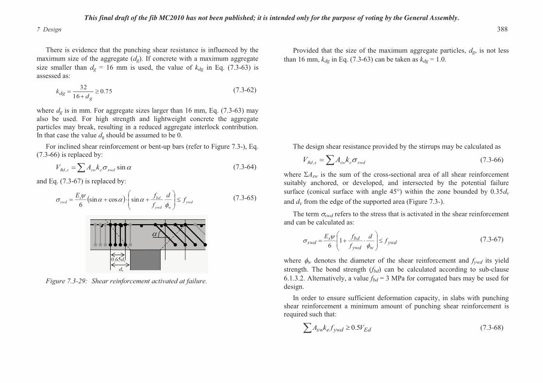
Figure 7.3-29: Shear reinforcement activated at failure.
The design shear resistance provided by the stirrups may be calculated as
�� swdeswsRd kAV �, (7.3-66)
where �Asw is the sum of the cross-sectional area of all shear reinforcement suitably anchored, or developed, and intersected by the potential failure surface (conical surface with angle 45°) within the zone bounded by 0.35dv
and dv from the edge of the supported area (Figure 7.3-).
The term �swd refers to the stress that is activated in the shear reinforcement and can be calculated as:
ywdwywd
bdsswd fd
ffE
����
����
����
�� 1
6(7.3-67)
where �w denotes the diameter of the shear reinforcement and fywd its yield strength. The bond strength (fbd) can be calculated according to sub-clause6.1.3.2. Alternatively, a value fbd = 3 MPa for corrugated bars may be used for design.
In order to ensure sufficient deformation capacity, in slabs with punching shear reinforcement a minimum amount of punching shear reinforcement is required such that:
Edywdesw VfkA 5.0�� (7.3-68)
This final draft of the fib MC2010 has not been published; it is intended only for the purpose of voting by the General Assembly.
Model Code 2010, Final draft 389
If more restrictive detailing rules are adopted (s0 � 0.5dv and s1 � 0.6dv,with s0 and s1 according to Figure 7.13-9 and if the placing of the transverse reinforcement is checked at the construction site (distance between transverse reinforcements, top and bottom cover), the value ksys can be increased as follows :
- ksys = 2.4 for stirrups with sufficient development length at the compression face of the slab and bent (no anchorages or development length) at the tension face
- ksys = 2.8 for studs (diameter of heads larger or equal than 3 times the bar diameter)
Other values may be used for the coefficient ksys provided that they are experimentally verified.
The maximum punching shear resistance is limited by crushing of the concrete struts in the supported area:
vc
ckv
c
cksysRd db
fdb
fkkV 00max, ��� �� (7.3-69)
The coefficient ksys accounts for the performance of punching shear reinforcing systems to control shear cracking and to suitably confine compression struts at the soffit of the slab. In absence of other data, andprovided that reinforcement is detailed as per the provisions of sub-clause7.13.5.3, a value ksys = 2.0 can be adopted.
7.3.5.4 Calculation of rotations around the supported area
Level I of ApproximationSlabs calculated under this assumption comply with deformation capacity
requirements stated in sub-clause 7.3.4.1.
The value of rs can be approximated as 0.22 Lx or 0.22 Ly for the x- and y-directions, respectively, for regular flat slabs where the ratio of the spans (Lx/Ly) is between 0.5 and 2.0. In Level I of Approximation, the maximum value of rs has to be considered in Eq. (7.3-70).
For a regular flat slab designed according to an elastic analysis without significant redistribution of internal forces, a safe estimate of the rotation at failure is:
s
ydsEf
dr�� 5.1� (7.3-70)
where rs denotes the position where the radial bending moment is zero with respect to the support axis
Level II of Approximation
The average bending moment acting in the support strip (msd) can be approximated for each reinforcement direction and support type as:
- For inner columns (top reinforcement in each direction):
��
�
�
��
�
�
���
s
iuEdsd b
eVm
281 , (7.3-71)
In cases where significant bending moment redistribution is considered in the design, the slab rotation can be calculated as:
5.15.1 ��
�
����
����
Rd
sd
s
ydsmm
Ef
dr
� (7.3-75)
where:
This final draft of the fib MC2010 has not been published; it is intended only for the purpose of voting by the General Assembly.
7 Design 390
- For edge columns: when calculations are made considering the tension reinforcement parallel to the edge:
4281 , Ed
s
iuEdsd
Vb
eVm ��
�
�
�
��
�
�
��� (7.3-72)
when calculations are made considering the tension reinforcement perpendicular to the edge:
��
�
�
��
�
���
s
iuEdsd b
eVm ,
81 (7.3-73)
- For corner columns (tension reinforcement in each direction):
281 , Ed
s
iuEdsd
Vbe
Vm ���
�
�
��
�
��� (7.3-74)
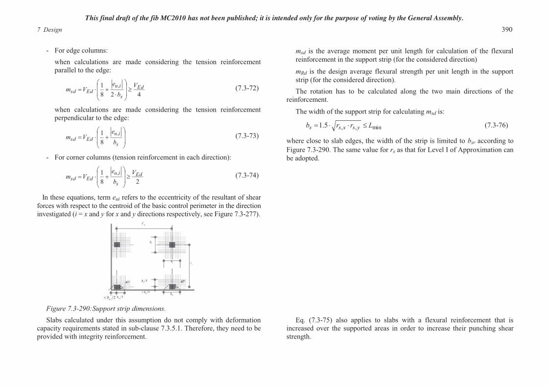
In these equations, term eui refers to the eccentricity of the resultant of shear forces with respect to the centroid of the basic control perimeter in the direction investigated (i = x and y for x and y directions respectively, see Figure 7.3-277).
Figure 7.3-290:Support strip dimensions.
msd is the average moment per unit length for calculation of the flexural reinforcement in the support strip (for the considered direction)
mRd is the design average flexural strength per unit length in the support strip (for the considered direction).The rotation has to be calculated along the two main directions of the
reinforcement.
The width of the support strip for calculating msd is:
min,,5.1 Lrrb ysxss ���� (7.3-76)
where close to slab edges, the width of the strip is limited to bsr according to Figure 7.3-290. The same value for rs as that for Level I of Approximation can be adopted.
Slabs calculated under this assumption do not comply with deformation capacity requirements stated in sub-clause 7.3.5.1. Therefore, they need to be provided with integrity reinforcement.
Eq. (7.3-75) also applies to slabs with a flexural reinforcement that is increased over the supported areas in order to increase their punching shear strength.
This final draft of the fib MC2010 has not been published; it is intended only for the purpose of voting by the General Assembly.

Model Code 2010, Final draft 391
The design average flexural strength per unit length in the support strip is to be calculated accounting for both ordinary and prestressing steel at yielding.
For prestressed slabs, Eq. (7.3-75) can be replaced by:5.1
5.1 ���
����
���
���PdRd
Pdsd
s
ydsmmmm
Ef
dr
� (7.3-77)
where mPd denotes the average decompression moment over the width of the support strip (bs) due to prestressing. Constrained forces and moments and losses due to shrinkage, creep and relaxation shall be taken into account.
Level III of ApproximationThis Level of Approximation is recommended for irregular slabs or for
flat slabs where the ratio of the span lengths (Lx/Ly) is not between 0.5 and 2.0.
Parameter msd has to be calculated consistently with the method used for determining the flexural reinforcement and is to be determined at the edge of the supported area maximizing msd, see Figure 7.3-31.
Figure 7.3-301. Example of sections for integration of support strip moments.
The coefficient 1.5 in Eqs. (7.3-75) and (7.3-77) can be replaced by 1.2 if:
- rs is calculated using a linear elastic (uncracked) model
- msd is calculated from a linear elastic (uncracked) model as the average value of the moment for design of the flexural reinforcement over the width of the support strip (bs)
The width of the support strip can be calculated as in Level II of Approximation taking rs,x and rs,y as the maximum value in the direction investigated. For edge or corner columns, the following minimum value of rshas to be considered:
srs br 67.0� (7.3-78)
Level IV of ApproximationAnalytical or numerical techniques (for example, finite elements, finite
differences, etc.) may be used for Level IV Approximation. The rotation � can be calculated on the basis of a nonlinear analysis of the
structure and accounting for cracking, tension-stiffening effects, yielding of the reinforcement and any other non-linear effects relevant for providing an accurate assessment of the structure.
This final draft of the fib MC2010 has not been published; it is intended only for the purpose of voting by the General Assembly.

7 Design 392
7.3.5.5 Punching shear resistance outside the zones with shear reinforcement or shearheads
Figure 7.3-312:Reduced control perimeter and shear-resisting effective depth.
The extent of the slab with shear-reinforcement can be determined by checking the resistance of the slab outside this region. Sub-clause 7.3.5.3 applies by accounting for a control perimeter with a maximum effective distance between two shear reinforcing elements of 3dv (Figure 7.3-312).
This final draft of the fib MC2010 has not been published; it is intended only for the purpose of voting by the General Assembly.

Model Code 2010, Final draft 393
Figure 7.3-323:Shear-resisting effective depth and control perimeter accounting for shearhead penetration.
The punching shear resistance of a slab outside of the shearhead is calculated on the basis of sub-clause 7.3.5.3 considering the shearhead as a rigidly supported area. The shear-resisting effective depth shall account for the position of the shearhead in the slab as shown in Figure 7.3-323.
7.3.5.6 Integrity reinforcementThe design shear for calculation of the integrity reinforcement can be
calculated on the basis of an accidental situation where progressive collapse has to be avoided.
Slabs without shear reinforcement, or with insufficient deformation capacity, shall be provided with integrity reinforcement (Figure 7.3-334) to avoid progressive collapse.
(a)
(b)
The resistance provided after punching by the integrity reinforcement can be calculated as:
� � intresc
ckultkytydsRd,int bd
ffffAV
��
5.0sin/ ��� (7.3-79)
where:- As refers to the sum of the cross-sections of all reinforcement suitably
developed beyond the supported area on the compression side of the slab or to well-anchored bent-up bars.
- fyd is the design yield strength of the integrity bars.- Ratio (ft /fy)k and parameter �uk are defined in sub-clause 5.2.5.4 and
depend on the ductility class of the reinforcement.- �ult is the angle of the integrity bar with respect to the slab plane at
failure (after development of plastic deformations in the post-punching regime).
This final draft of the fib MC2010 has not been published; it is intended only for the purpose of voting by the General Assembly.

7 Design 394
(c)
Figure 7.3-334:Integrity reinforcement: (a) straight bars; (b) bent-up bars; and (c) example of arrangement of integrity reinforcement (plan view, As equals to 12 cross-sections, bint summed for 4 groups of bars).
The integrity reinforcement should at least be composed of four bars placed over the supported area and correctly developed on the compression side of the slab. Post-tensioning tendons can also be considered as integrity reinforcement.
In order to allow full activation of the integrity bars, the diameter of the integrity bars (�int) has to be chosen such that: �int � 0.12dres.
�ult Type of integrity reinforcement
0° Straight bars, class of ductility: A20° Straight bars, class of ductility: B25° Straight bars, class of ductility: C or D
�� 40� Inclined or bent-up bars, class of ductility: B, C or Dwhere � is the angle of the integrity bars with respect to the slab plane (before punching occurs), see Figure 7.3-33
- dres is the distance between the centroid of the flexural reinforcement ratio and the centroid of the integrity reinforcement, see Figure 7.3-334(a) and (b).
- bint is the control perimeter activated by the integrity reinforcement after punching. It can be calculated as:
� � )2
( resintint dsb � (7.3-80)
where the summation refers to the groups of bars activated at the edge of the supported area and sint is equal to the width of the group of bars (refer to Figure 7.3-334).
7.3.6 Design with stress fields and strut and tie models
7.3.6.1 General Structures can be subdivided into B-regions, where the assumption of a
plane section may be used (B for Bernoulli) and D-regions, where a non-linear strain distribution exists (D for discontinuity); D-regions typically are located at supports or at places of concentrated loads.
This final draft of the fib MC2010 has not been published; it is intended only for the purpose of voting by the General Assembly.
Related Documents