PD-008 Iss 6 Installation & Operation Manual 12/08/2008 Bell System (Telephones) Ltd Model 719S 2 Door Switching Unit PD-008 Iss 6

Welcome message from author
This document is posted to help you gain knowledge. Please leave a comment to let me know what you think about it! Share it to your friends and learn new things together.
Transcript

PD-008 Iss 6 Installation & Operation Manual 12/08/2008
Bell System (Telephones) Ltd
Model 719S2 Door Switching Unit
PD-008 Iss 6
719S 2 Door Switching Unit
PD-008 Iss 6 Installation & Operation Manual Page 2 of 20
Table of Contents
GENERAL DESCRIPTION ........................................................................................ 3
OPERATION .............................................................................................................. 3TELEPHONES ............................................................................................................ 3POWER SUPPLY........................................................................................................ 3ELECTRIC LOCK RELEASE / MAGLOCK ........................................................................ 4EGRESS FACILITY...................................................................................................... 4TRADESMAN FACILITY................................................................................................ 4DOOR STATUS INDICATION ......................................................................................... 4SYSTEMS WITH 3 OR MORE DOORS ........................................................................... 4SETTINGS ................................................................................................................. 5
Speech Active Time ............................................................................................ 5Lock Release Time ............................................................................................. 5Mode Setting....................................................................................................... 5
IMPORTANT SAFETY INFORMATION..................................................................... 6
INSTALLATION ......................................................................................................... 7
CABLE REQUIREMENTS.............................................................................................. 8TROUBLESHOOTING................................................................................................... 9
Test Button.......................................................................................................... 9LED Status Indicators ......................................................................................... 9Problem and Cause ............................................................................................ 9Technical Specification ..................................................................................... 12
DIAGRAM 1: WIRING FOR 2 DOOR AC SYSTEMS ........................................................ 13DIAGRAM 2: 719S AC INTERCONNECTIONS FOR SYSTEMS OF 3 – 16 DOORS.............. 14DIAGRAM 3: WIRING DIAGRAM FOR 2 DOOR DC SYSTEMS.......................................... 15DIAGRAM 4: 719S DC INTERCONNECTIONS FOR SYSTEMS OF 3 – 16 DOORS ............. 16DIAGRAM 5: DISTRIBUTION OF COMMON CABLES OF BS-LX PHONES .......................... 17DIAGRAM 6: CONNECTION OF ADDITIONAL PSU FOR 21-60 BS-LX PHONES ............... 18DIAGRAM 7: DOOR CONTACT / SWITCH WIRING ......................................................... 19
MANUFACTURER DETAILS................................................................................... 20
STANDARDS........................................................................................................... 20
719S 2 Door Switching Unit
PD-008 Iss 6 Installation & Operation Manual Page 3 of 20
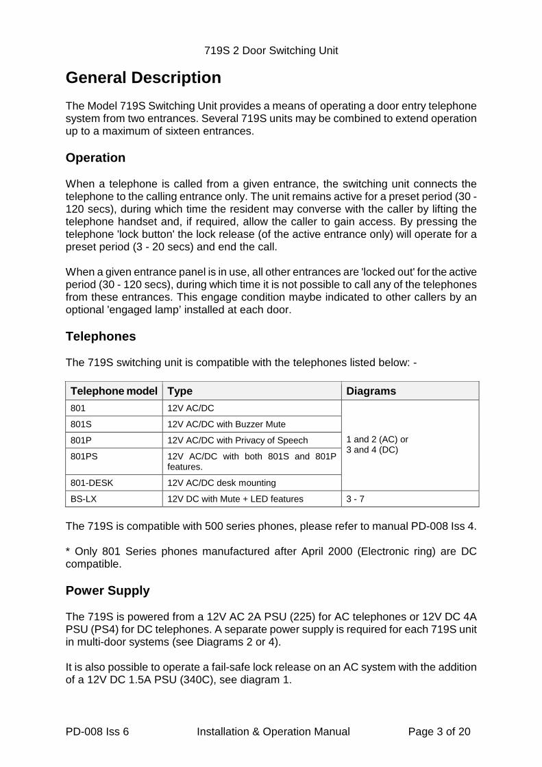
General Description
The Model 719S Switching Unit provides a means of operating a door entry telephonesystem from two entrances. Several 719S units may be combined to extend operationup to a maximum of sixteen entrances.
Operation
When a telephone is called from a given entrance, the switching unit connects thetelephone to the calling entrance only. The unit remains active for a preset period (30 -120 secs), during which time the resident may converse with the caller by lifting thetelephone handset and, if required, allow the caller to gain access. By pressing thetelephone 'lock button' the lock release (of the active entrance only) will operate for apreset period (3 - 20 secs) and end the call.
When a given entrance panel is in use, all other entrances are 'locked out' for the activeperiod (30 - 120 secs), during which time it is not possible to call any of the telephonesfrom these entrances. This engage condition maybe indicated to other callers by anoptional 'engaged lamp’ installed at each door.
Telephones
The 719S switching unit is compatible with the telephones listed below: -
Telephone model Type Diagrams
801 12V AC/DC
1 and 2 (AC) or3 and 4 (DC)
801S 12V AC/DC with Buzzer Mute
801P 12V AC/DC with Privacy of Speech
801PS 12V AC/DC with both 801S and 801Pfeatures.
801-DESK 12V AC/DC desk mounting
BS-LX 12V DC with Mute + LED features 3 - 7
The 719S is compatible with 500 series phones, please refer to manual PD-008 Iss 4.
* Only 801 Series phones manufactured after April 2000 (Electronic ring) are DCcompatible.
Power Supply
The 719S is powered from a 12V AC 2A PSU (225) for AC telephones or 12V DC 4APSU (PS4) for DC telephones. A separate power supply is required for each 719S unitin multi-door systems (see Diagrams 2 or 4).
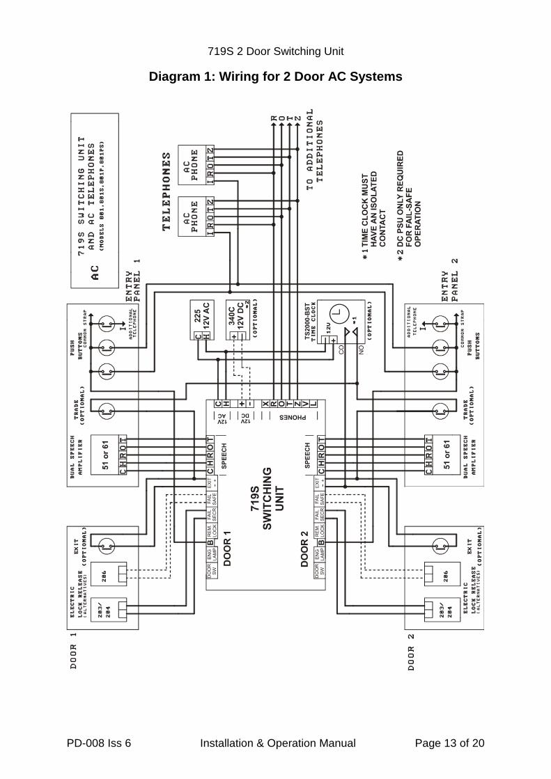
It is also possible to operate a fail-safe lock release on an AC system with the additionof a 12V DC 1.5A PSU (340C), see diagram 1.
719S 2 Door Switching Unit
PD-008 Iss 6 Installation & Operation Manual Page 4 of 20
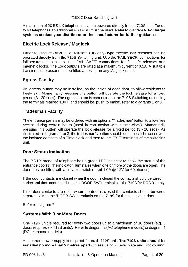
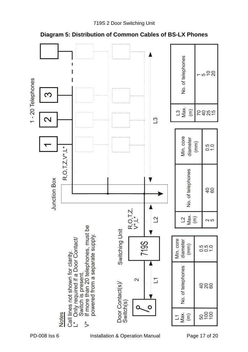
A maximum of 20 BS-LX telephones can be powered directly from a 719S unit. For upto 60 telephones an additional PS4 PSU must be used. Refer to diagram 6. For largersystems contact your distributor or the manufacturer for further guidance.
Electric Lock Release / Maglock
Either fail-secure (AC/DC) or fail-safe (DC only) type electric lock releases can beoperated directly from the 719S Switching unit. Use the 'FAIL SECR' connections forfail-secure releases. Use the 'FAIL SAFE' connections for fail-safe releases andmagnetic locks. The Lock outputs are rated at a maximum current of 0.5A. A suitabletransient suppressor must be fitted across or in any Maglock used.
Egress Facility
An 'egress' button may be installed, on the inside of each door, to allow residents tofreely exit. Momentarily pressing this button will operate the lock release for a fixedperiod (3 - 20 secs). The egress button is connected to the 719S Switching unit usingthe terminals marked 'EXIT' and should be ‘push to make’, refer to diagrams 1 or 3.
Tradesman Facility
The entrance panels may be ordered with an optional 'Tradesman' button to allow freeaccess during certain hours (used in conjunction with a time-clock). Momentarilypressing this button will operate the lock release for a fixed period (3 - 20 secs). Asillustrated in diagrams 1 or 3, the tradesman's button should be connected in series withthe isolated contacts of a Time clock and then to the 'EXIT' terminals of the switchingunit.
Door Status Indication
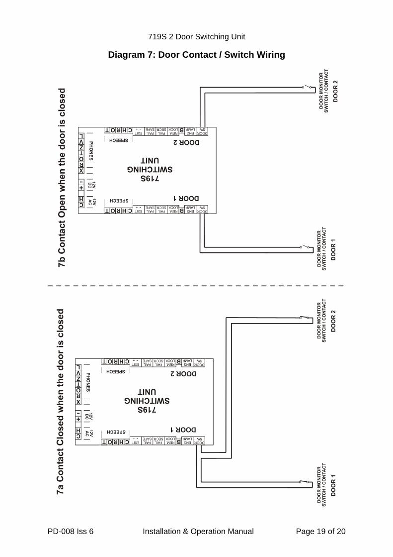
The BS-LX model of telephone has a green LED indicator to show the status of theentrance door(s); the indicator illuminates when one or more of the doors are open. Thedoor must be fitted with a suitable switch (rated 1.0A @ 12V for 60 phones).
If the door contacts are closed when the door is closed the contacts should be wired inseries and then connected into the ‘DOOR SW’ terminals on the 719S for DOOR 1 only.
If the door contacts are open when the door is closed the contacts should be wiredseparately in to the ‘DOOR SW’ terminals on the 719S for the associated door.
Refer to diagram 7.
Systems With 3 or More Doors
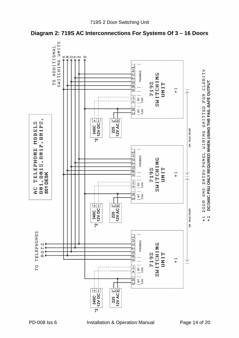
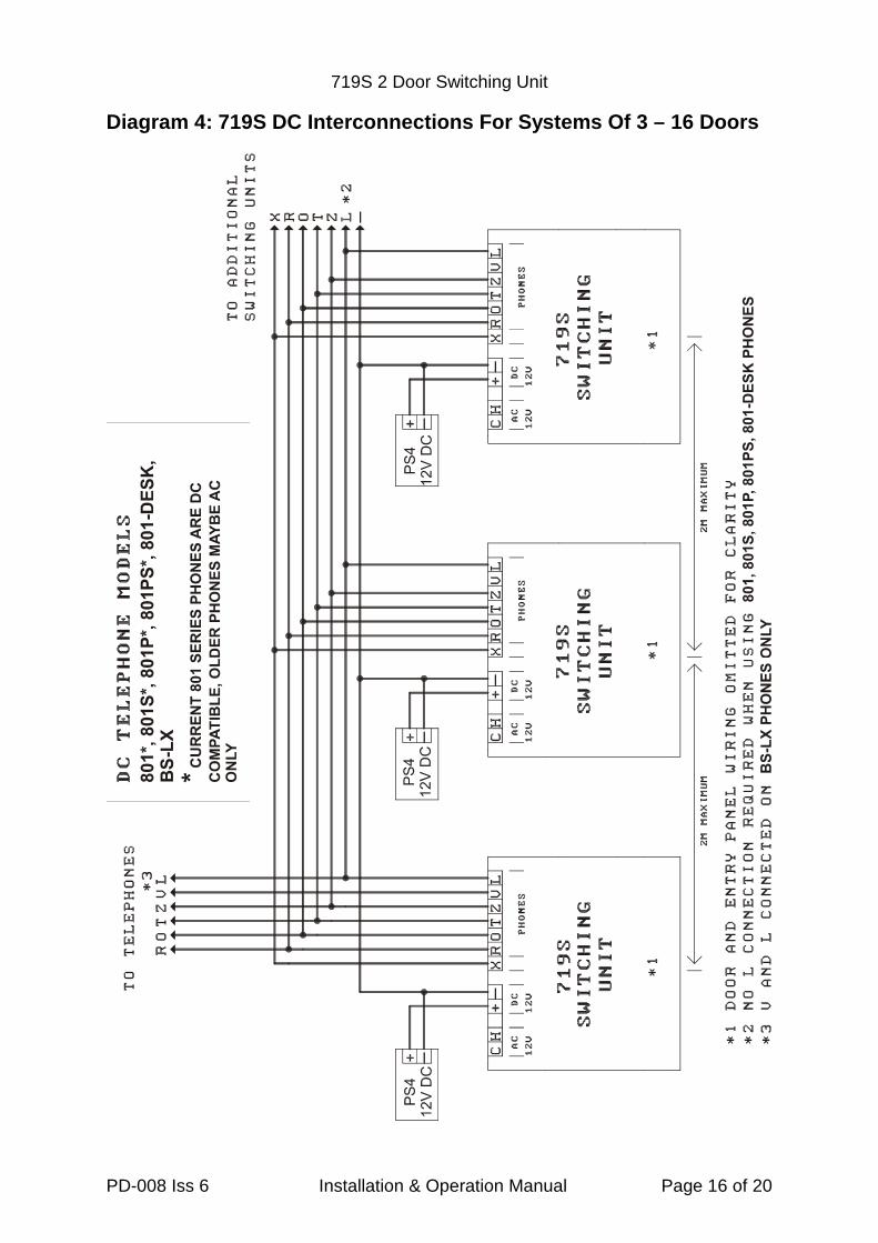
One 719S unit is required for every two doors up to a maximum of 16 doors (e.g. 5doors requires 3 x 719S units). Refer to diagram 2 (AC telephone models) or diagram 4(DC telephone models).
A separate power supply is required for each 719S unit. The 719S units should beinstalled no more than 2 metres apart (unless using 2 Level Gate and Block wiring,
719S 2 Door Switching Unit
PD-008 Iss 6 Installation & Operation Manual Page 5 of 20
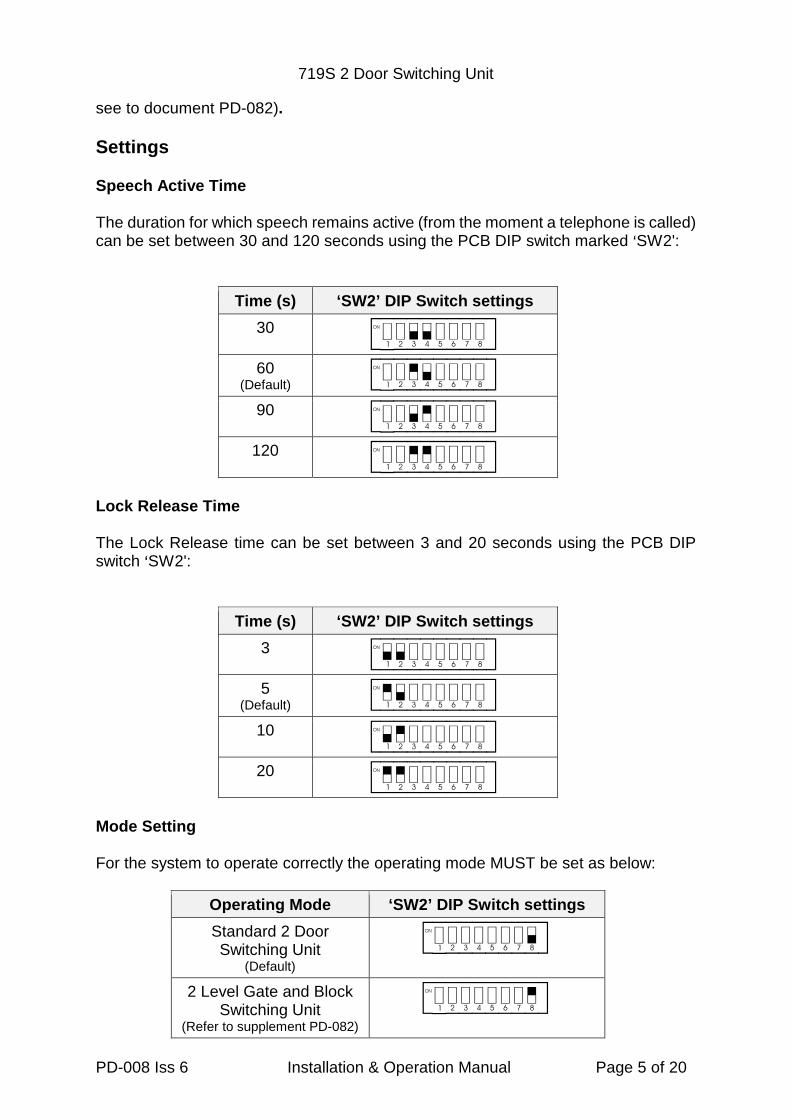
see to document PD-082).
Settings
Speech Active Time
The duration for which speech remains active (from the moment a telephone is called)can be set between 30 and 120 seconds using the PCB DIP switch marked >SW2':
Time (s) ‘SW2’ DIP Switch settings
30[aserghjk]
60(Default) [as3rghjk]
90[ase4ghjk]
120[as34ghjk]
Lock Release Time
The Lock Release time can be set between 3 and 20 seconds using the PCB DIPswitch >SW2':
Time (s) ‘SW2’ DIP Switch settings
3[qwdfghjk]
5(Default) [1wdfghjk]
10[q2dfghjk]
20[12dfghjk]
Mode Setting
For the system to operate correctly the operating mode MUST be set as below:
Operating Mode ‘SW2’ DIP Switch settings
Standard 2 DoorSwitching Unit
(Default)
[asdfghji]
2 Level Gate and BlockSwitching Unit
(Refer to supplement PD-082)
[asdfghj8]
719S 2 Door Switching Unit
PD-008 Iss 6 Installation & Operation Manual Page 6 of 20
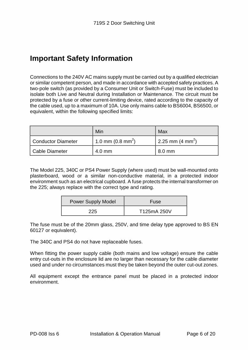
Important Safety Information
Connections to the 240V AC mains supply must be carried out by a qualified electricianor similar competent person, and made in accordance with accepted safety practices. Atwo-pole switch (as provided by a Consumer Unit or Switch-Fuse) must be included toisolate both Live and Neutral during Installation or Maintenance. The circuit must beprotected by a fuse or other current-limiting device, rated according to the capacity ofthe cable used, up to a maximum of 10A. Use only mains cable to BS6004, BS6500, orequivalent, within the following specified limits:
Min Max
Conductor Diameter 1.0 mm (0.8 mm2) 2.25 mm (4 mm2)
Cable Diameter 4.0 mm 8.0 mm
The Model 225, 340C or PS4 Power Supply (where used) must be wall-mounted ontoplasterboard, wood or a similar non-conductive material, in a protected indoorenvironment such as an electrical cupboard. A fuse protects the internal transformer onthe 225; always replace with the correct type and rating.
Power Supply Model Fuse
225 T125mA 250V
The fuse must be of the 20mm glass, 250V, and time delay type approved to BS EN60127 or equivalent).
The 340C and PS4 do not have replaceable fuses.
When fitting the power supply cable (both mains and low voltage) ensure the cableentry cut-outs in the enclosure lid are no larger than necessary for the cable diameterused and under no circumstances must they be taken beyond the outer cut-out zones.
All equipment except the entrance panel must be placed in a protected indoorenvironment.
719S 2 Door Switching Unit
PD-008 Iss 6 Installation & Operation Manual Page 7 of 20
Installation
Initially connect all the equipment to one telephone ONLY. With the power applied, testthe system is fully operational. Connect one telephone at a time and test beforeproceeding.

719S 2 Door Switching Unit
PD-008 Iss 6 Installation & Operation Manual Page 8 of 20
Cable Requirements
Use standard 0.5mm solid core twisted-pair CAT5/CAT5e unshielded or CW1308telephone cable for all connections unless otherwise specified. Do not use strandedalarm cable. For optimum speech clarity a twisted-pair must be used for the 'R' and 'O'connections to telephone and speech unit. Avoid running any cables alongside mains orother transmission wiring.
The Total number of cores depends on the requirement for each telephone model asshown in the table below. In all cases there is an individual call line for each phone,while the remainder of the cores are common to all phones in the system. All telephonemodels, except the BS-LX, may be wired either with an individual cable or by loopingfrom phone to phone.
Care must be taken with the BS-LX model to avoid voltage drop problems (due to LEDcurrents from mute and door status features). Refer to the tables on diagram 5 andbelow before planning the cable layout for these models. If in doubt please contactyour distributor or the manufacturer for further guidance.
Connection No. ofcores
MaxLength
ConductorSize
801,801S, 801P or 801PSPhone
5 100m 0.5mm dia.
BS-LX Phone 7See diagram 5
BS-LX (no door contact, no ’L’) 6
Power Supply 2 2m 1.0mm2
Speech Unit 5 50m 0.5mm dia.
Lock Release (up to 0.5A) 2 25m50m
0.5mm dia.1.0mm2
EXIT/Trades Button(inc. Time Clock
2 100m 0.5mm dia.
Door Monitor Contact 2 See diagram 5 and 7
719S 2 Door Switching Unit
PD-008 Iss 6 Installation & Operation Manual Page 9 of 20
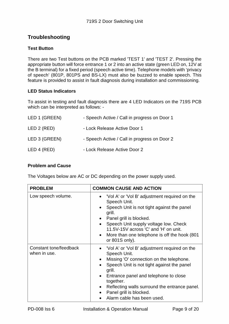
Troubleshooting
Test Button
There are two Test buttons on the PCB marked 'TEST 1' and 'TEST 2'. Pressing theappropriate button will force entrance 1 or 2 into an active state (green LED on, 12V atthe B terminal) for a fixed period (speech active time). Telephone models with ‘privacyof speech’ (801P, 801PS and BS-LX) must also be buzzed to enable speech. Thisfeature is provided to assist in fault diagnosis during installation and commissioning.
LED Status Indicators
To assist in testing and fault diagnosis there are 4 LED Indicators on the 719S PCBwhich can be interpreted as follows: -
LED 1 (GREEN) - Speech Active / Call in progress on Door 1
LED 2 (RED) - Lock Release Active Door 1
LED 3 (GREEN) - Speech Active / Call in progress on Door 2
LED 4 (RED) - Lock Release Active Door 2
Problem and Cause
The Voltages below are AC or DC depending on the power supply used.
PROBLEM COMMON CAUSE AND ACTION
Low speech volume. 'Vol A' or 'Vol B' adjustment required on theSpeech Unit.
Speech Unit is not tight against the panelgrill.
Panel grill is blocked. Speech Unit supply voltage low. Check
11.5V-15V across 'C' and 'H' on unit. More than one telephone is off the hook (801
or 801S only).
Constant tone/feedbackwhen in use.
'Vol A' or 'Vol B' adjustment required on theSpeech Unit.
Missing 'O' connection on the telephone. Speech Unit is not tight against the panel
grill. Entrance panel and telephone to close
together. Reflecting walls surround the entrance panel. Panel grill is blocked. Alarm cable has been used.
719S 2 Door Switching Unit
PD-008 Iss 6 Installation & Operation Manual Page 10 of 20
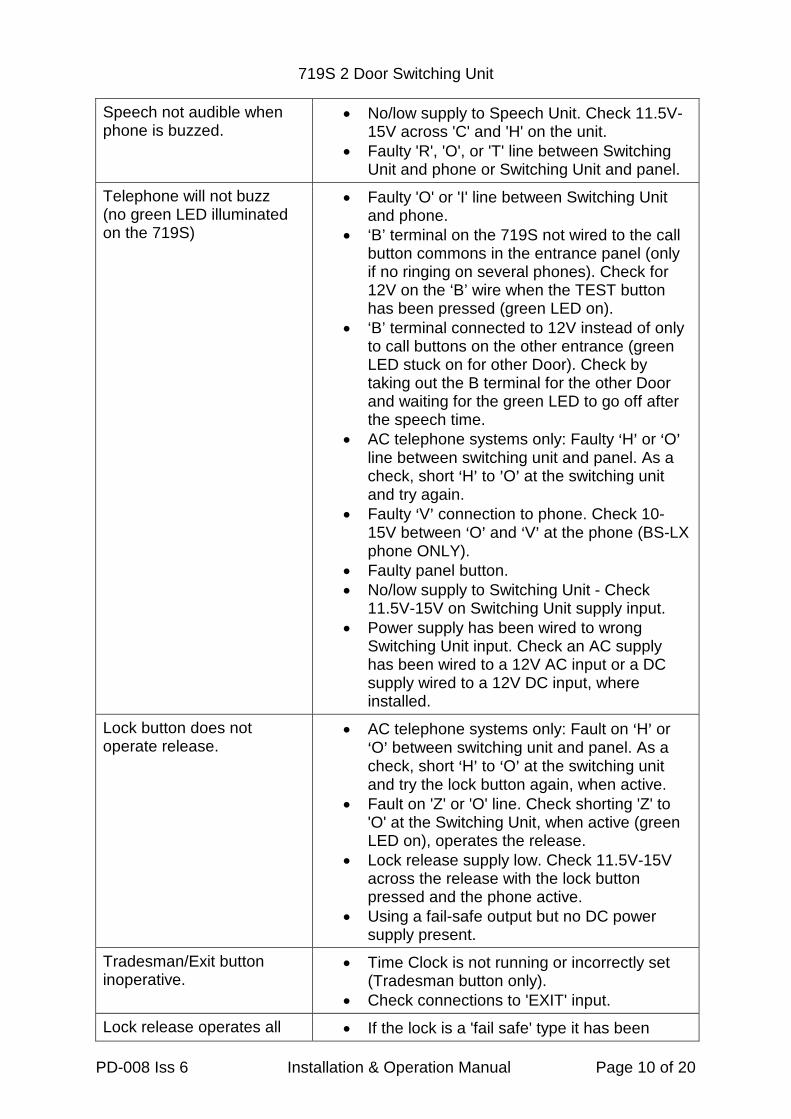
Speech not audible whenphone is buzzed.
No/low supply to Speech Unit. Check 11.5V-15V across 'C' and 'H' on the unit.
Faulty 'R', 'O', or 'T' line between SwitchingUnit and phone or Switching Unit and panel.
Telephone will not buzz(no green LED illuminatedon the 719S)
Faulty 'O' or 'I' line between Switching Unitand phone.
‘B’ terminal on the 719S not wired to the callbutton commons in the entrance panel (onlyif no ringing on several phones). Check for12V on the ‘B’ wire when the TEST buttonhas been pressed (green LED on).
‘B’ terminal connected to 12V instead of onlyto call buttons on the other entrance (greenLED stuck on for other Door). Check bytaking out the B terminal for the other Doorand waiting for the green LED to go off afterthe speech time.
AC telephone systems only: Faulty >H= or >O=line between switching unit and panel. As acheck, short >H= to =O= at the switching unitand try again.
Faulty >V= connection to phone. Check 10-15V between >O= and >V= at the phone (BS-LXphone ONLY).
Faulty panel button. No/low supply to Switching Unit - Check
11.5V-15V on Switching Unit supply input. Power supply has been wired to wrong
Switching Unit input. Check an AC supplyhas been wired to a 12V AC input or a DCsupply wired to a 12V DC input, whereinstalled.
Lock button does notoperate release.
AC telephone systems only: Fault on >H= or>O= between switching unit and panel. As acheck, short >H= to >O= at the switching unitand try the lock button again, when active.
Fault on 'Z' or 'O' line. Check shorting 'Z' to'O' at the Switching Unit, when active (greenLED on), operates the release.
Lock release supply low. Check 11.5V-15Vacross the release with the lock buttonpressed and the phone active.
Using a fail-safe output but no DC powersupply present.
Tradesman/Exit buttoninoperative.
Time Clock is not running or incorrectly set(Tradesman button only).
Check connections to 'EXIT' input.
Lock release operates all If the lock is a 'fail safe' type it has been
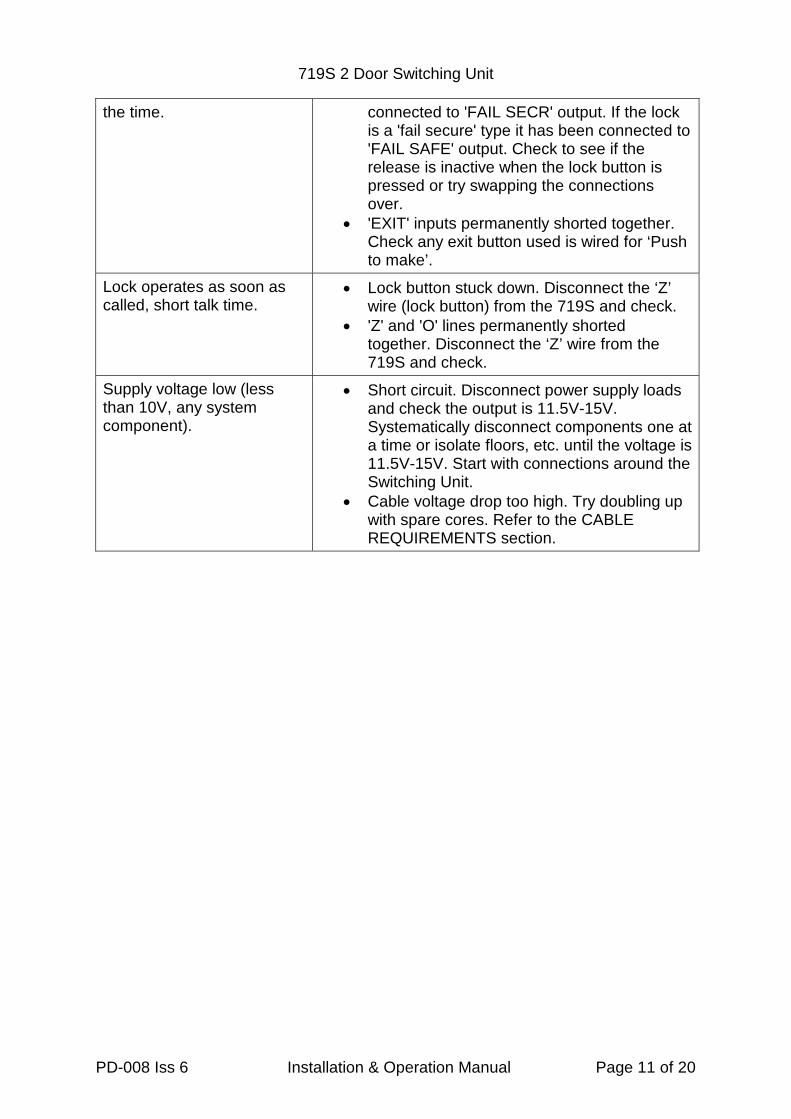
719S 2 Door Switching Unit
PD-008 Iss 6 Installation & Operation Manual Page 11 of 20
the time. connected to 'FAIL SECR' output. If the lockis a 'fail secure' type it has been connected to'FAIL SAFE' output. Check to see if therelease is inactive when the lock button ispressed or try swapping the connectionsover.
'EXIT' inputs permanently shorted together.Check any exit button used is wired for ‘Pushto make’.
Lock operates as soon ascalled, short talk time.
Lock button stuck down. Disconnect the ‘Z’wire (lock button) from the 719S and check.
'Z' and 'O' lines permanently shortedtogether. Disconnect the ‘Z’ wire from the719S and check.
Supply voltage low (lessthan 10V, any systemcomponent).
Short circuit. Disconnect power supply loadsand check the output is 11.5V-15V.Systematically disconnect components one ata time or isolate floors, etc. until the voltage is11.5V-15V. Start with connections around theSwitching Unit.
Cable voltage drop too high. Try doubling upwith spare cores. Refer to the CABLEREQUIREMENTS section.
719S 2 Door Switching Unit
PD-008 Iss 6 Installation & Operation Manual Page 12 of 20
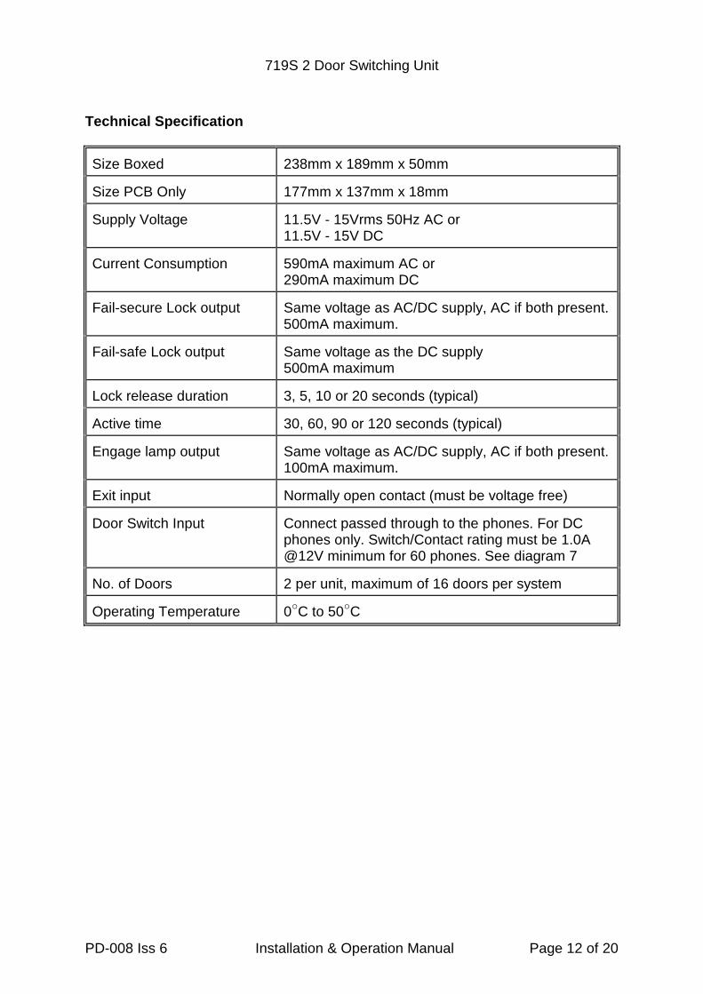
Technical Specification
Size Boxed 238mm x 189mm x 50mm
Size PCB Only 177mm x 137mm x 18mm
Supply Voltage 11.5V - 15Vrms 50Hz AC or11.5V - 15V DC
Current Consumption 590mA maximum AC or290mA maximum DC
Fail-secure Lock output Same voltage as AC/DC supply, AC if both present.500mA maximum.
Fail-safe Lock output Same voltage as the DC supply500mA maximum
Lock release duration 3, 5, 10 or 20 seconds (typical)
Active time 30, 60, 90 or 120 seconds (typical)
Engage lamp output Same voltage as AC/DC supply, AC if both present.100mA maximum.
Exit input Normally open contact (must be voltage free)
Door Switch Input Connect passed through to the phones. For DCphones only. Switch/Contact rating must be 1.0A@12V minimum for 60 phones. See diagram 7
No. of Doors 2 per unit, maximum of 16 doors per system
Operating Temperature 0"C to 50"C
719S 2 Door Switching Unit
PD-008 Iss 6 Installation & Operation Manual Page 13 of 20
Diagram 1: Wiring for 2 Door AC Systems
719S 2 Door Switching Unit
PD-008 Iss 6 Installation & Operation Manual Page 14 of 20
Diagram 2: 719S AC Interconnections For Systems Of 3 – 16 Doors

719S 2 Door Switching Unit
PD-008 Iss 6 Installation & Operation Manual Page 15 of 20
Diagram 3: Wiring Diagram for 2 Door DC Systems
719S 2 Door Switching Unit
PD-008 Iss 6 Installation & Operation Manual Page 16 of 20
Diagram 4: 719S DC Interconnections For Systems Of 3 – 16 Doors
719S 2 Door Switching Unit
PD-008 Iss 6 Installation & Operation Manual Page 17 of 20
Diagram 5: Distribution of Common Cables of BS-LX Phones

719S 2 Door Switching Unit
PD-008 Iss 6 Installation & Operation Manual Page 18 of 20
Diagram 6: Connection Of Additional PSU for 21-60 BS-LX Phones
719S 2 Door Switching Unit
PD-008 Iss 6 Installation & Operation Manual Page 19 of 20
Diagram 7: Door Contact / Switch Wiring

719S 2 Door Switching Unit
PD-008 Iss 6 Installation & Operation Manual Page 20 of 20
Manufacturer Details
Bell System (Telephones) Ltd.
Presley Way,
Crown Hill,
Milton Keynes
MK8 0ET.
Tel: 01908 261106 (Sales and Technical Support)
FAX: 01908 261116
OR
Local rate numbers
Tel: 0845 121 4008 (Sales and Technical Support)
FAX: 0845 121 4009
E-mail: [email protected]
Website: www.bellsystem.co.uk
StandardsThis product complies with European directive 89/336/EEC on
Electromagnetic Compatibility and Low Voltage Directive 72/23/EEC.
Emissions: Generic BSEN 50081-1
Immunity: Generic BSEN 50082-1
Low Voltage: Generic BSEN 60950
BS EN ISO 9001:2000 Certificate number GB2000389
Related Documents