VIBROENGINEERING. JOURNAL OF VIBROENGINEERING. MARCH 2011. VOLUME 14, ISSUE 1. ISSN 1392-8716 39 715. Transients in the electromagnetic actuator with the controlled supplier Bronislaw Tomczuk, Andrzej Waindok, Dawid Wajnert Opole University of Technology, Department of Industrial Electrical Engineering Proszkowska str. 76, 45-758 Opole, Poland E-mail: [email protected], [email protected], [email protected] (Received 11 September 2011; accepted 14 February 2012) Abstract. A calculation of transients in the electromagnetic actuator with the controlled supplier has been presented in the paper. The magnetic field model of the actuator has been created with using the finite element method (FEM) and verified experimentally. The mathematical models of the supplier and controller have been coupled with the field-circuit model of the actuator using Matlab/Simulink package. The circuit parameters have been obtained from the FEM calculations. The algorithm of the proportionally-integral (PI) controller operation has been implemented. The transients of position, current and force, for different controller parameters, have been obtained. The calculation results have been verified by the measurement tests. Keywords: control systems, linear actuators, coupled field-circuit model, modelling of mechatronic systems. Introduction The electromagnetic linear actuators and motors are used as a linear drives in different applications [1, 2], e.g. suspension systems, fatigue stands [3], generators of vibrations [4] and oscillators [5, 6]. There are growing demands for such special electric motors. In each application (e.g. CNC machines) the proper control and supply systems are needed. In most cases an ordinary PI or PID controllers can be applied. The modelling of such controllers becomes more important due to design costs. Instead making of the physical control system, we can build and investigate its mathematic model. Thus, we can study transients in the system including changing the controller parameters. After this, we can implement the parameters in the real prototype. The limits of the parameters could be obtained by calculations. Thus, we are able to introduce them in the tests without destroying the physical models. In this paper we consider the electromagnetic actuator (Fig. 1) build in the controlled fatigue stand. The box of the control-supplying system is presented on the right side of Fig. 1. We can see that the controlled supplier is very small. Fig. 1. The actuator in the fatigue stand with the controlled supplier

Welcome message from author
This document is posted to help you gain knowledge. Please leave a comment to let me know what you think about it! Share it to your friends and learn new things together.
Transcript

VIBROENGINEERING. JOURNAL OF VIBROENGINEERING. MARCH 2011. VOLUME 14, ISSUE 1. ISSN 1392-8716
39
715. Transients in the electromagnetic actuator with the controlled supplier Bronisław Tomczuk, Andrzej Waindok, Dawid Wajnert Opole University of Technology, Department of Industrial Electrical Engineering Proszkowska str. 76, 45-758 Opole, Poland E-mail: [email protected], [email protected], [email protected]
(Received 11 September 2011; accepted 14 February 2012)
Abstract. A calculation of transients in the electromagnetic actuator with the controlled supplier has been presented in the paper. The magnetic field model of the actuator has been created with using the finite element method (FEM) and verified experimentally. The mathematical models of the supplier and controller have been coupled with the field-circuit model of the actuator using Matlab/Simulink package. The circuit parameters have been obtained from the FEM calculations. The algorithm of the proportionally-integral (PI) controller operation has been implemented. The transients of position, current and force, for different controller parameters, have been obtained. The calculation results have been verified by the measurement tests.
Keywords: control systems, linear actuators, coupled field-circuit model, modelling of mechatronic systems. Introduction
The electromagnetic linear actuators and motors are used as a linear drives in different applications [1, 2], e.g. suspension systems, fatigue stands [3], generators of vibrations [4] and oscillators [5, 6]. There are growing demands for such special electric motors. In each application (e.g. CNC machines) the proper control and supply systems are needed. In most cases an ordinary PI or PID controllers can be applied. The modelling of such controllers becomes more important due to design costs. Instead making of the physical control system, we can build and investigate its mathematic model. Thus, we can study transients in the system including changing the controller parameters. After this, we can implement the parameters in the real prototype. The limits of the parameters could be obtained by calculations. Thus, we are able to introduce them in the tests without destroying the physical models.
In this paper we consider the electromagnetic actuator (Fig. 1) build in the controlled fatigue stand. The box of the control-supplying system is presented on the right side of Fig. 1. We can see that the controlled supplier is very small.
Fig. 1. The actuator in the fatigue stand with the controlled supplier
715. TRANSIENTS IN THE ELECTROMAGNETIC ACTUATOR WITH THE CONTROLLED SUPPLIER.
BRONISŁAW TOMCZUK, ANDRZEJ WAINDOK , DAWID WAJNERT
VIBROENGINEERING. JOURNAL OF VIBROENGINEERING. MARCH 2012. VOLUME 14, ISSUE 1. ISSN 1392-8716 40
Both, mathematical and physical models have been done within the presented work. The parameters of the electromagnetic actuator, which is visible on he left side of Fig. 1, have been calculated with the finite element method (FEM) [7] through the magnetic field analysis. We have used the FEMM software [8]. The whole device i.e. actuator and its control supplier has been simulated with Matlab/Simulink software package. We have modelled the PI controller and the pulse width modulation (PWM) power supplier and the mathematical model of the actuator (Fig. 2). The stresses in the lever of the fatigue stand and the tested specimen were calculated with Femap software [9]. Modelling of the actuator transients
For the modelling of the actuator transients the voltage u excitation has been forced. In our modelling, the runner position z and the current i are the functions to be calculated. The Lagrange method has been adopted for the formulation of the ordinary differential equations [10, 11], which describe the unknown quantities:
m
mgzDzkkziF
dt
zd sL +−+−
=
ɺ)(),(2
2
(1)
( )
),(
),(
d
d
d ziL
vz
ziRiu
t
i ⋅∂
Ψ∂−−
= (2)
where the parameters are: ks, kL – the spring and fatigued specimen constant respectively, D – the friction coefficient, m – mass of the runner, zv ɺ= – velocity of the runner, F(i, z) – force characteristic, R – coil electrical resistance, ),(d ziL - dynamic inductance characteristic, ),( ziΨ
- linkage flux characteristic. The characteristics of the functions F(i, z), ),(d ziL , ( , )i zΨ have
been presented in Figs. 3 and 4. The values of the remaining parameters are given in Table 1.
dPsi(i,z)/dz
1s
Velocity53000*u
Specimen resi lience
Sine Wave
-K-
R
Product1
Product
Position1
1s
Position
Duty
Current
Voltage
PWM
Ld(i ,z)
-C-
Gravi tation force
Force
f(u)
Fcn
F(i,z)
Duty
InOut
Discrete PI Control ler
50
D
Current1
1s
Current
Add
-K-
1/mass
Fig. 2. The model of the actuator with the controlled supplier
The integral parameters of the magnetic field are: thrust, magnetic flux and winding
dynamic inductance. They have been obtained from the magnetic flux density distribution. We have used FEM calculations. The geometry of the actuator can be presented in the axial

715. TRANSIENTS IN THE ELECTROMAGNETIC ACTUATOR WITH THE CONTROLLED SUPPLIER.
BRONISŁAW TOMCZUK, ANDRZEJ WAINDOK , DAWID WAJNERT
VIBROENGINEERING. JOURNAL OF VIBROENGINEERING. MARCH 2012. VOLUME 14, ISSUE 1. ISSN 1392-8716 41
coordinate system r, φ, z. The thrust has been obtained using the expression for the Lorentz force [12]:
( )∫ ϕϕ−π=
S
zrrz rdrdzBJBJF 112
(3)
The flux value has been calculated as the integral of the magnetic vector potential [13]. The dynamic inductance is very important in the simulation of the operation of the actuator under voltage supplying. Its value has been calculated as the current derivative of the flux linkage [14]:
∑∫=
ϕ=Ψ
N
k kl
klA1
d (4) di
zidLd
),(Ψ= (5)
where N is the number of turns in the actuator winding.
The equations (1) and (2) have been solved in the Matlab/Simulink package [15]. The supplying through the pulse width modulation (PWM) system and the control systems were included in the mathematical model (Fig. 2).
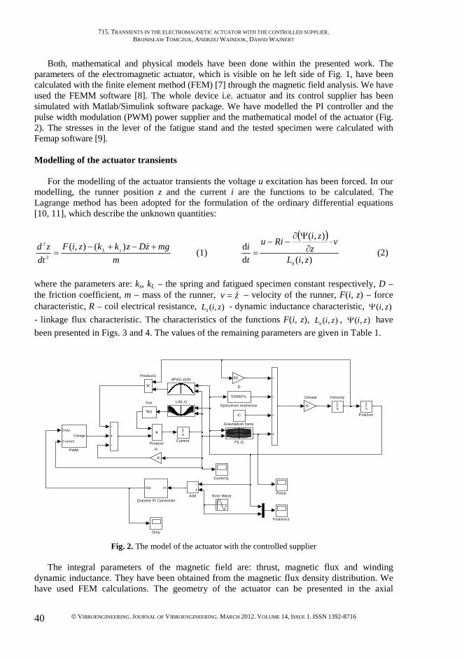
The force characteristic (Fig. 3a) is important for the control algorithm. The thrust values change linearly vs. the current excitation values. The thrust characteristic is only slightly nonlinear for the high current intensity in the excitation coil. The flux inside the winding depends almost only on the mover position (Fig. 3b). The dynamic inductance, which is very important value in the transient model, is almost constant (Fig. 4a). The characteristic in Fig. 4b, which is used in the calculation of the electromotive force (EMF), depends only on the mover position. The smooth shapes of the presented characteristics are very convenient for the quick and precise analysis of the actuator transients.
Fig. 3. The characteristics verso mover position z and the excitation current I of: a) thrust F, b) flux Ψ
The parameters in Table 1 have been obtained both from measurements and calculations.
The resistance values of the coil and the mover mass have been measured before the other parameters determination. The friction coefficient value has been assumed taking into account the mover and stator materials. The sum of the spring and specimen constants has been calculated including the stress values (Femap software [9]).
Table 1. Constant parameters of the field-circuit model
Parameter Resistance
R [Ω] Mover mass
m [g] Friction coefficient
D [Ns/m2] Constant
ks + kL [N/mm] Value 8.27 255 50 53
715. TRANSIENTS IN THE ELECTROMAGNETIC ACTUATOR WITH THE CONTROLLED SUPPLIER.
BRONISŁAW TOMCZUK, ANDRZEJ WAINDOK , DAWID WAJNERT
VIBROENGINEERING. JOURNAL OF VIBROENGINEERING. MARCH 2012. VOLUME 14, ISSUE 1. ISSN 1392-8716 42
Fig. 4. The characteristics of: a) dynamic inductance Ld, b) position derivative of the magnetic flux
Calculation results
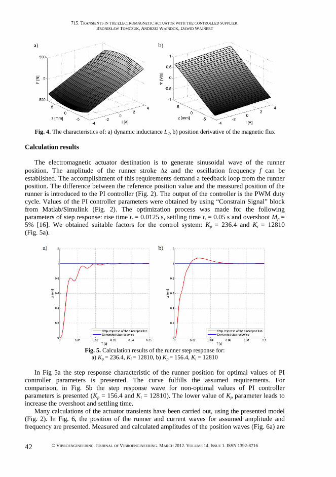
The electromagnetic actuator destination is to generate sinusoidal wave of the runner position. The amplitude of the runner stroke ∆z and the oscillation frequency f can be established. The accomplishment of this requirements demand a feedback loop from the runner position. The difference between the reference position value and the measured position of the runner is introduced to the PI controller (Fig. 2). The output of the controller is the PWM duty cycle. Values of the PI controller parameters were obtained by using “Constrain Signal” block from Matlab/Simulink (Fig. 2). The optimization process was made for the following parameters of step response: rise time tr = 0.0125 s, settling time ts = 0.05 s and overshoot Mp = 5% [16]. We obtained suitable factors for the control system: Kp = 236.4 and Ki = 12810 (Fig. 5a).
Fig. 5. Calculation results of the runner step response for:
a) Kp = 236.4, Ki = 12810, b) Kp = 156.4, Ki = 12810
In Fig 5a the step response characteristic of the runner position for optimal values of PI controller parameters is presented. The curve fulfills the assumed requirements. For comparison, in Fig. 5b the step response wave for non-optimal values of PI controller parameters is presented (Kp = 156.4 and Ki = 12810). The lower value of Kp parameter leads to increase the overshoot and settling time.
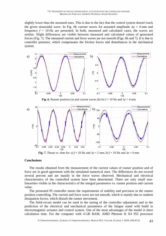
Many calculations of the actuator transients have been carried out, using the presented model (Fig. 2). In Fig. 6, the position of the runner and current waves for assumed amplitude and frequency are presented. Measured and calculated amplitudes of the position waves (Fig. 6a) are
715. TRANSIENTS IN THE ELECTROMAGNETIC ACTUATOR WITH THE CONTROLLED SUPPLIER.
BRONISŁAW TOMCZUK, ANDRZEJ WAINDOK , DAWID WAJNERT
VIBROENGINEERING. JOURNAL OF VIBROENGINEERING. MARCH 2012. VOLUME 14, ISSUE 1. ISSN 1392-8716 43
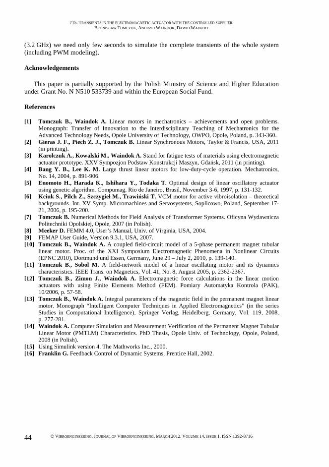
slightly lower than the assumed ones. This is due to the fact that the control system doesn't track the given sinusoidal wave. In Fig. 6b current waves for assumed amplitude ∆z = 4 mm and frequency f = 10 Hz are presented. In both, measured and calculated cases, the waves are similar. Slight differences are visible between measured and calculated values of generated forces (Fig. 7). The measured current and force waves are not smooth (Figs. 6b and 7). It is due to controller presence, which compensates the friction forces and disturbances in the mechanical system.
Fig. 6. Runner position (a) and current waves (b) for f = 10 Hz and ∆z = 4 mm
Fig. 7. Thrust vs. time for: a) f = 20 Hz and ∆z = 2 mm, b) f = 10 Hz and ∆z = 4 mm
Conclusions
The results obtained from the measurement of the current values of runner position and of force are in good agreement with the simulated numerical ones. The differences do not exceed several percent and are mainly in the force waves observed. Mechanical and electrical characteristics of the controlled system have been determined. There are only small non-linearities visible in the characteristics of the integral parameters vs. runner position and current value.
The presented PI controller meets the requirements of stability and precision in the runner position controlling. The current and force wave are not smooth, which is mainly due to random dissipation forces, which disturb the runner movement.
The field-circuit model can be used in the tuning of the controller adjustment and in the prediction of the electrical and mechanical parameters of the fatigue stand with build in electromagnetic actuator and control system. One of the most advantages of the model is short calculation time. For the computer with 4 GB RAM, AMD Phenom II X4 955 processor
715. TRANSIENTS IN THE ELECTROMAGNETIC ACTUATOR WITH THE CONTROLLED SUPPLIER.
BRONISŁAW TOMCZUK, ANDRZEJ WAINDOK , DAWID WAJNERT
VIBROENGINEERING. JOURNAL OF VIBROENGINEERING. MARCH 2012. VOLUME 14, ISSUE 1. ISSN 1392-8716 44
(3.2 GHz) we need only few seconds to simulate the complete transients of the whole system (including PWM modeling).
Acknowledgements
This paper is partially supported by the Polish Ministry of Science and Higher Education under Grant No. N N510 533739 and within the European Social Fund. References [1] Tomczuk B., Waindok A. Linear motors in mechatronics – achievements and open problems.
Monograph: Transfer of Innovation to the Interdisciplinary Teaching of Mechatronics for the Advanced Technology Needs, Opole University of Technology, OWPO, Opole, Poland, p. 343-360.
[2] Gieras J. F., Piech Z. J., Tomczuk B. Linear Synchronous Motors, Taylor & Francis, USA, 2011 (in printing).
[3] Karolczuk A., Kowalski M., Waindok A. Stand for fatigue tests of materials using electromagnetic actuator prototype. XXV Sympozjon Podstaw Konstrukcji Maszyn, Gdańsk, 2011 (in printing).
[4] Bang Y. B., Lee K. M. Large thrust linear motors for low-duty-cycle operation. Mechatronics, No. 14, 2004, p. 891-906.
[5] Enomoto H., Harada K., Ishihara Y., Todaka T. Optimal design of linear oscillatory actuator using genetic algorithm. Compumag, Rio de Janeiro, Brasil, November 3-6, 1997, p. 131-132.
[6] Kciuk S., Pilch Z., Szczygieł M., Trawiński T. VCM motor for active vibroisolation – theoretical backgrounds. Int. XV Symp. Micromachines and Servosystems, Soplicowo, Poland, September 17-21, 2006, p. 195-200.
[7] Tomczuk B. Numerical Methods for Field Analysis of Transformer Systems. Oficyna Wydawnicza Politechniki Opolskiej, Opole, 2007 (in Polish).
[8] Meeker D. FEMM 4.0, User’s Manual, Univ. of Virginia, USA, 2004. [9] FEMAP User Guide, Version 9.3.1, USA, 2007. [10] Tomczuk B., Waindok A. A coupled field-circuit model of a 5-phase permanent magnet tubular
linear motor. Proc. of the XXI Symposium Electromagnetic Phenomena in Nonlinear Circuits (EPNC 2010), Dortmund und Essen, Germany, June 29 – July 2, 2010, p. 139-140.
[11] Tomczuk B., Sobol M. A field-network model of a linear oscillating motor and its dynamics characteristics. IEEE Trans. on Magnetics, Vol. 41, No. 8, August 2005, p. 2362-2367.
[12] Tomczuk B., Zimon J., Waindok A. Electromagnetic force calculations in the linear motion actuators with using Finite Elements Method (FEM). Pomiary Automatyka Kontrola (PAK), 10/2006, p. 57-58.
[13] Tomczuk B., Waindok A. Integral parameters of the magnetic field in the permanent magnet linear motor. Monograph “Intelligent Computer Techniques in Applied Electromagnetics” (in the series Studies in Computational Intelligence), Springer Verlag, Heidelberg, Germany, Vol. 119, 2008, p. 277-281.
[14] Waindok A. Computer Simulation and Measurement Verification of the Permanent Magnet Tubular Linear Motor (PMTLM) Characteristics. PhD Thesis, Opole Univ. of Technology, Opole, Poland, 2008 (in Polish).
[15] Using Simulink version 4. The Mathworks Inc., 2000. [16] Franklin G. Feedback Control of Dynamic Systems, Prentice Hall, 2002.
Related Documents