1 Migrating a DxDesigner Library to Allegro Design Entry HDL Michael Catrambone Distinguished Engineer PCB/Mechanical Silicon Valley 2007 September 10-12, 2007 San Jose, CA

Welcome message from author
This document is posted to help you gain knowledge. Please leave a comment to let me know what you think about it! Share it to your friends and learn new things together.
Transcript
1
Migrating a DxDesigner Library to Allegro Design Entry HDL
Michael Catrambone Distinguished Engineer
PCB/MechanicalSilicon Valley 2007September 10-12, 2007
San Jose, CA
2
Preface
• We are currently using DxDesigner to generate our schematics on the front-end and using Allegro on the back-end for PCB Development.
• It seems to make sense to use the Cadence schematic capture tools on the front-end to improve the Front to Back flow integration.
• As a company, we are moving towards a Cadence Front to Back flow worldwide and we want to leverage our existing libraries.– Attempting to move from one EDA front-end tool to another is a
daunting task.– You will need an understanding of your current DxDatabook library
structure and what elements of the library are important to you and your company.
– Having to rebuild a Library with several thousand parts can take many man-months. It would be nice to bring that IP over as painlessly as possible.
• This paper will describe the process and tough choices that weremade in order to migrate our DxDatabook library over to a Cadence Allegro Design Entry HDL environment.
3
Goals and Expectations
• Goals– Leverage a massive DxDatabook Library and build an Allegro Design Entry HDL
Library which can be used with proven Allegro package symbols.– Easily maintain the Allegro Design Entry HDL library and have the ability to re-
target new library entries to DxDatabook libraries.
• Expectations– Resulting Allegro Design Entry HDL Library should not have any custom
attributes that only have meaning in DxDesigner.– Library elements should be transitioned as follows:
• DxDesigner graphic symbols Allegro Design Entry HDL graphic symbols• DxDatabook records Cadence Part Table Files (ptf)
– At the time of this translation it was not possible to link an Access DB directly to Allegro Design Entry HDL to retrieve Part information so Part Tables were constructed for each of the components.
– Package functionality like pin and gate swapping should be supported in the Allegro Design Entry HDL library.
– Library structure should be similar to the DxDatabook Library.– Netlist information from Allegro Design Entry HDL should contain the same
information as a schematic generated using DxDesigner.
4
Reality
• Things to be considered– Is your current library built to specific guidelines and worth leveraging in the
creation of the new library?• If this is not the case you are going to have major difficulty and unexpected
results in the new library that will take a lot of time to troubleshoot and correct.
– Do you fully understand the value of the original library investments? • It is a multi-year investment.
– Is it time to develop library guidelines and rebuild your library from scratch?• Having to rebuild a Library with several thousand parts can take several
man-months even with fully dedicated resources.
– Why not create the schematic library symbols on the fly as needed on a per-project basis so after a year or so of projects the library will almost be completed?
• We will discuss this in detail on the next slide.
– Is the difficulty of a library translation project understood by management?• A “Push the button” translation is really not available.
5
Reality
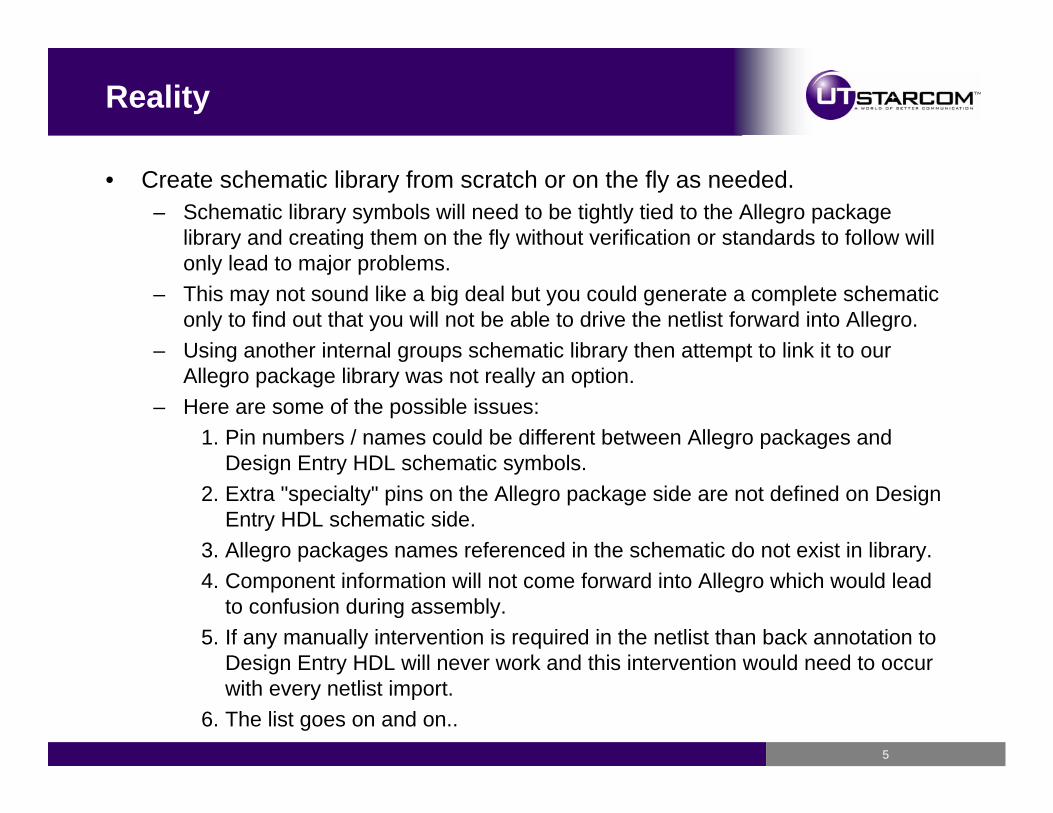
• Create schematic library from scratch or on the fly as needed.– Schematic library symbols will need to be tightly tied to the Allegro package
library and creating them on the fly without verification or standards to follow will only lead to major problems.
– This may not sound like a big deal but you could generate a complete schematic only to find out that you will not be able to drive the netlist forward into Allegro.
– Using another internal groups schematic library then attempt to link it to our Allegro package library was not really an option.
– Here are some of the possible issues:1. Pin numbers / names could be different between Allegro packages and
Design Entry HDL schematic symbols.2. Extra "specialty" pins on the Allegro package side are not defined on Design
Entry HDL schematic side.3. Allegro packages names referenced in the schematic do not exist in library.4. Component information will not come forward into Allegro which would lead
to confusion during assembly.5. If any manually intervention is required in the netlist than back annotation to
Design Entry HDL will never work and this intervention would need to occur with every netlist import.
6. The list goes on and on..
6
What options do we have?
• Things we evaluated to help ease the transition:– Outsource the library development and build the library from scratch
• Can be very costly.• The resulting library could be very fragmented and inconsistent.• Extra time required to develop library specifications based on
Allegro Design Entry HDL.– Cadence VIEWLOGIC2CON
• Converts symbols from DxDesigner to ConceptHDL and possibly schematics.
• Requires Librarian Expert and can be a time consuming process.– CADPlex Symbol Publisher
• Provides software and services to take symbol libraries, individual schematic pages or entire schematics from one EDA format to another. A bi-directional interface to/from the following EDA Tools:
– Cadence Allegro Design Entry HDL, Orcad Capture– Mentor DX Designer, Mentor DA
• Time is of the essence so it would be nice to bring the libraries over as painlessly as possible.
7
Why we chose Cadplex ?
• They had both DxDatabook and Allegro Design Entry HDL in-house.
• They understood both tools well and were willing to customize their library retargeting tools to meet our needs and automate the entire translation process.
• They provided a fixed bid price which included setup costs, migration of a sample set of the library followed by the entire library.
• To speed up the process we decided to first convert one of our very large schematics over to Allegro Design Entry HDL in the hopes that the resulting schematic library could be used for future projects.
8
Schematic conversion to build libraries
• Schematic came across fine but we ran into some functionality differences between Allegro Design Entry HDL and DxDesignerwhich made the resulting library not usable.– All of our DxDesigner schematics use the functionality to scale the
schematic symbols to any size we like at the schematic level.– Our libraries are built to one scale and Allegro Design Entry HDL does
not have the functionality to scale the schematic symbols at theschematic level so the translation falls short.
– Resulting library would have multiple versions of the same component to support the different scaling possibilities.
• Converting schematics to build a schematic library seemed like agood option but with the scaling issue, among other minor issues, it was decided to pursue a full library translation.
• The first phase of our DxDatabook transition was to convert a select group of common reuse sections between two of our major projectsand create an Allegro Design Entry HDL schematic.
9
Translate, build and verify libraries
• Provided the following to CadPlex for library generation– Stripped down DxDesigner Schematic with only common reuse sections
used as reference for the translation.– Archived library of the DxDesigner graphical symbols. (120 unique part
numbers)– DxDatabook Access Database which contains all component
information.
• After the Allegro Design Entry HDL library was generated we performed the following verification steps:– Created a DxDesigner Schematic then forward annotated it to Allegro.– Created an Allegro Design Entry HDL Schematic matching the
DxDesigner Schematic then forward annotated it to Allegro.– Utilized the Design Compare functionality in Allegro to verify the
DxDesigner and the Allegro Design Entry HDL based Allegro databases to insure connectivity and component attributes were maintained.
10
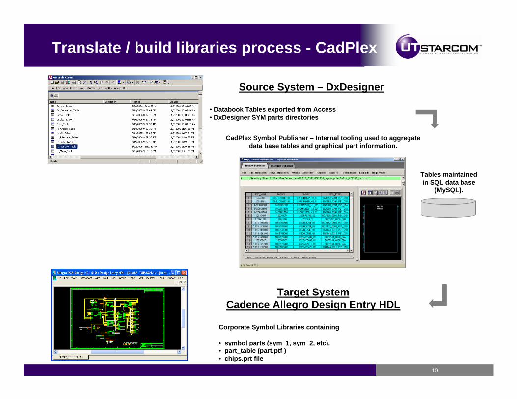
Source System – DxDesigner
• Databook Tables exported from Access• DxDesigner SYM parts directories
CadPlex Symbol Publisher – Internal tooling used to aggregate data base tables and graphical part information.
Tables maintainedin SQL data base
(MySQL).
Target SystemCadence Allegro Design Entry HDL
Corporate Symbol Libraries containing
• symbol parts (sym_1, sym_2, etc).• part_table (part.ptf )• chips.prt file
Translate / build libraries process - CadPlex
11
Initial Project Setup - CadPlex
• Understanding naming and attribute conventions.
• Part mapping from DxDesigner ( library / sym ) directory format to Allegro Design Entry HDL ( library / part / view ) directory format.
• Slice / Dice / and Re-Assembly of the symbol part data (SYM directory) and the DxDatabook tables into a format required by Allegro Design Entry HDL consisting of symbols, Chips.prt , and PTF table files.
• Hetero Devices part mapping– Multi-part hetero devices merged to a single Chips.prt file that
represents the assembly of the multiple parts.– Single part / gate hetero devices merged to a single Chips.prt file that
represents the mappings of the individual devices.
12
Initial Project Setup - CadPlex
• DxDatabook Library preparation for library transfer– 95 % of the symbols and tables did not require any tuning.– 5 % of the symbols and tables did require some type of tuning to
accurately transfer the content.• Strip out and replace special characters in pin names that are legal
in DxDesigner but illegal in Allegro Design Entry HDL.• Strip out inverted pin names (over bar above pin name) and replace
with underscores at the end of pin name.• Strip out attributes attached to graphics symbols that are used as
place holders and will not be required in Allegro Design Entry HDL.
• As the case with any translation or conversion there are a lot of surprises and unexpected results that need to be researched thenresolved on the fly. The effort to translate our DxDatabook library to Allegro Design Entry HDL was NOT the exception.
13
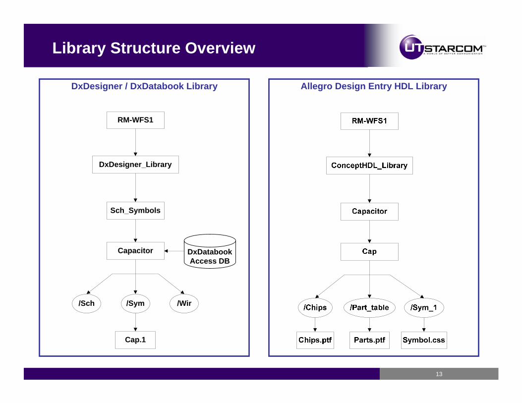
Library Structure Overview
RM-WFS1
DxDesigner_Library
Sch_Symbols
Capacitor
/Sch /Sym /Wir
Cap.1
DxDatabookAccess DB
DxDesigner / DxDatabook Library Allegro Design Entry HDL Library
14
DxDatabook Library Structure Overview
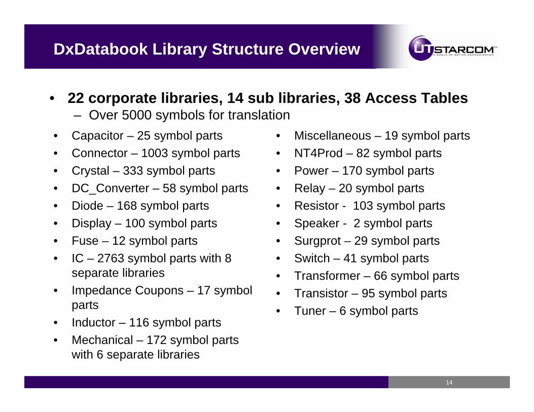
• Capacitor – 25 symbol parts• Connector – 1003 symbol parts• Crystal – 333 symbol parts• DC_Converter – 58 symbol parts• Diode – 168 symbol parts• Display – 100 symbol parts• Fuse – 12 symbol parts• IC – 2763 symbol parts with 8
separate libraries• Impedance Coupons – 17 symbol
parts• Inductor – 116 symbol parts• Mechanical – 172 symbol parts
with 6 separate libraries
• Miscellaneous – 19 symbol parts • NT4Prod – 82 symbol parts• Power – 170 symbol parts• Relay – 20 symbol parts• Resistor - 103 symbol parts• Speaker - 2 symbol parts• Surgprot – 29 symbol parts• Switch – 41 symbol parts• Transformer – 66 symbol parts• Transistor – 95 symbol parts• Tuner – 6 symbol parts
• 22 corporate libraries, 14 sub libraries, 38 Access Tables– Over 5000 symbols for translation
15
Library verification – Lessons learned
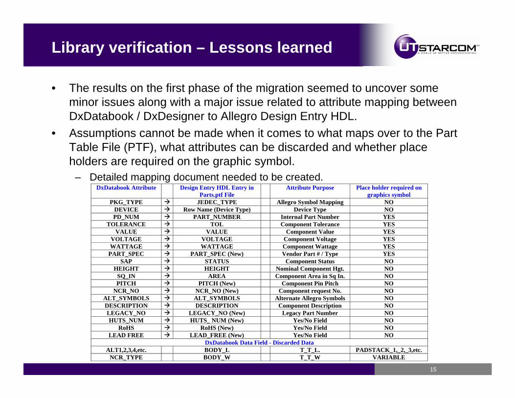
• The results on the first phase of the migration seemed to uncover some minor issues along with a major issue related to attribute mapping between DxDatabook / DxDesigner to Allegro Design Entry HDL.
• Assumptions cannot be made when it comes to what maps over to the Part Table File (PTF), what attributes can be discarded and whether place holders are required on the graphic symbol.
– Detailed mapping document needed to be created.DxDatabook Attribute Design Entry HDL Entry in
Parts.ptf File Attribute Purpose Place holder required on
graphics symbol PKG_TYPE JEDEC_TYPE Allegro Symbol Mapping NO
DEVICE Row Name (Device Type) Device Type NO PD_NUM PART_NUMBER Internal Part Number YES
TOLERANCE TOL Component Tolerance YES VALUE VALUE Component Value YES
VOLTAGE VOLTAGE Component Voltage YES WATTAGE WATTAGE Component Wattage YES
PART_SPEC PART_SPEC (New) Vendor Part # / Type YES SAP STATUS Component Status NO
HEIGHT HEIGHT Nominal Component Hgt. NO SQ_IN AREA Component Area in Sq In. NO PITCH PITCH (New) Component Pin Pitch NO
NCR_NO NCR_NO (New) Component request No. NO ALT_SYMBOLS ALT_SYMBOLS Alternate Allegro Symbols NO DESCRIPTION DESCRIPTION Component Description NO LEGACY_NO LEGACY_NO (New) Legacy Part Number NO HUTS_NUM HUTS_ NUM (New) Yes/No Field NO
RoHS RoHS (New) Yes/No Field NO LEAD FREE LEAD_FREE (New) Yes/No Field NO
DxDatabook Data Field - Discarded Data ALT1,2,3,4,etc. BODY_L T_T_L. PADSTACK_1,_2,_3,etc.
NCR_TYPE BODY_W T_T_W VARIABLE
16
Library verification – Lessons learned
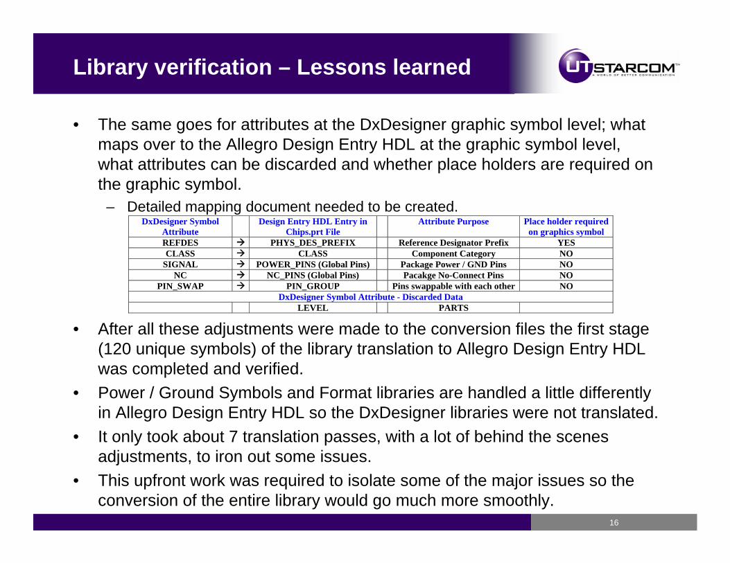
• The same goes for attributes at the DxDesigner graphic symbol level; what maps over to the Allegro Design Entry HDL at the graphic symbol level, what attributes can be discarded and whether place holders are required on the graphic symbol.
– Detailed mapping document needed to be created.DxDesigner Symbol
Attribute Design Entry HDL Entry in
Chips.prt File Attribute Purpose Place holder required
on graphics symbol REFDES PHYS_DES_PREFIX Reference Designator Prefix YES CLASS CLASS Component Category NO
SIGNAL POWER_PINS (Global Pins) Package Power / GND Pins NO NC NC_PINS (Global Pins) Pacakge No-Connect Pins NO
PIN_SWAP PIN_GROUP Pins swappable with each other NO DxDesigner Symbol Attribute - Discarded Data
LEVEL PARTS
• After all these adjustments were made to the conversion files the first stage (120 unique symbols) of the library translation to Allegro Design Entry HDL was completed and verified.
• Power / Ground Symbols and Format libraries are handled a little differently in Allegro Design Entry HDL so the DxDesigner libraries were not translated.
• It only took about 7 translation passes, with a lot of behind the scenes adjustments, to iron out some issues.
• This upfront work was required to isolate some of the major issues so the conversion of the entire library would go much more smoothly.
17
Library structure – Lessons learned
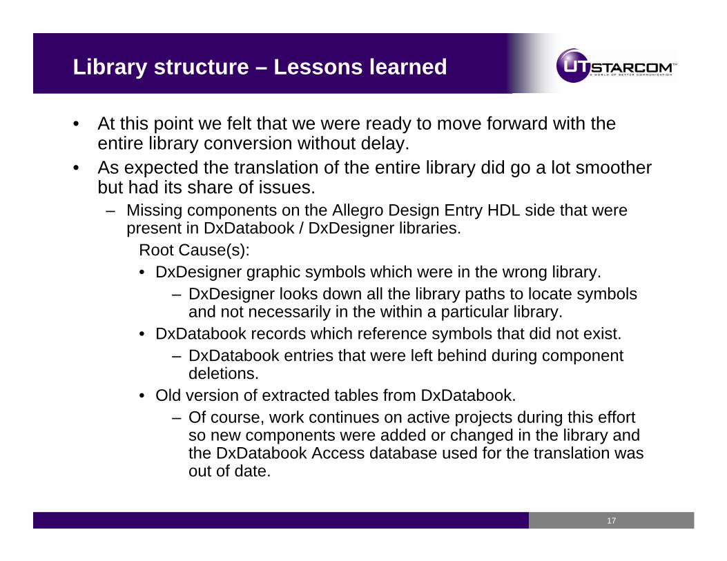
• At this point we felt that we were ready to move forward with the entire library conversion without delay.
• As expected the translation of the entire library did go a lot smoother but had its share of issues.– Missing components on the Allegro Design Entry HDL side that were
present in DxDatabook / DxDesigner libraries. Root Cause(s): • DxDesigner graphic symbols which were in the wrong library.
– DxDesigner looks down all the library paths to locate symbols and not necessarily in the within a particular library.
• DxDatabook records which reference symbols that did not exist.– DxDatabook entries that were left behind during component
deletions.• Old version of extracted tables from DxDatabook.
– Of course, work continues on active projects during this effort so new components were added or changed in the library and the DxDatabook Access database used for the translation was out of date.
18
Library attribute issues
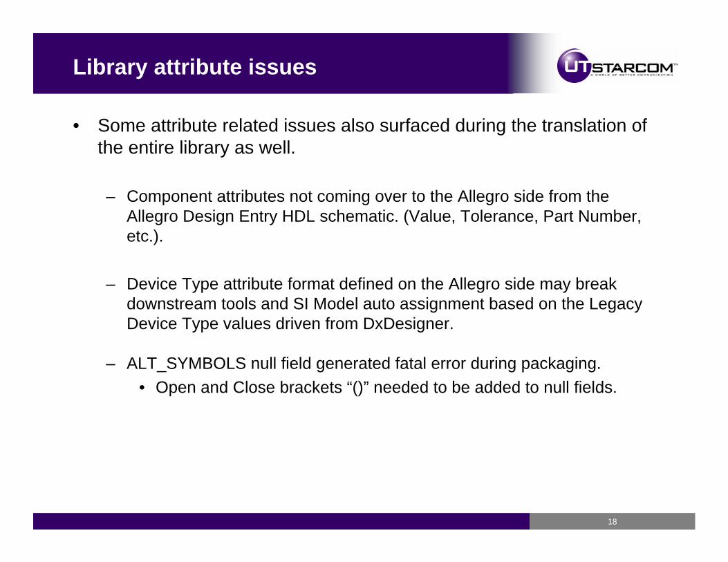
• Some attribute related issues also surfaced during the translation of the entire library as well.
– Component attributes not coming over to the Allegro side from the Allegro Design Entry HDL schematic. (Value, Tolerance, Part Number, etc.).
– Device Type attribute format defined on the Allegro side may break downstream tools and SI Model auto assignment based on the Legacy Device Type values driven from DxDesigner.
– ALT_SYMBOLS null field generated fatal error during packaging.• Open and Close brackets “()” needed to be added to null fields.
19
DxDesigner Attribute Passing - Explained
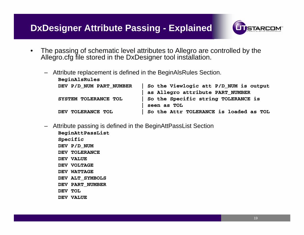
• The passing of schematic level attributes to Allegro are controlled by the Allegro.cfg file stored in the DxDesigner tool installation.
– Attribute replacement is defined in the BeginAlsRules Section.BeginAlsRulesDEV P/D_NUM PART_NUMBER | So the Viewlogic att P/D_NUM is output
| as Allegro attribute PART_NUMBERSYSTEM TOLERANCE TOL | So the Specific string TOLERANCE is
| seen as TOLDEV TOLERANCE TOL | So the Attr TOLERANCE is loaded as TOL
– Attribute passing is defined in the BeginAttPassList SectionBeginAttPassListSpecificDEV P/D_NUMDEV TOLERANCEDEV VALUEDEV VOLTAGEDEV WATTAGEDEV ALT_SYMBOLSDEV PART_NUMBERDEV TOL DEV VALUE
20
Allegro Design Entry HDL PTF File format
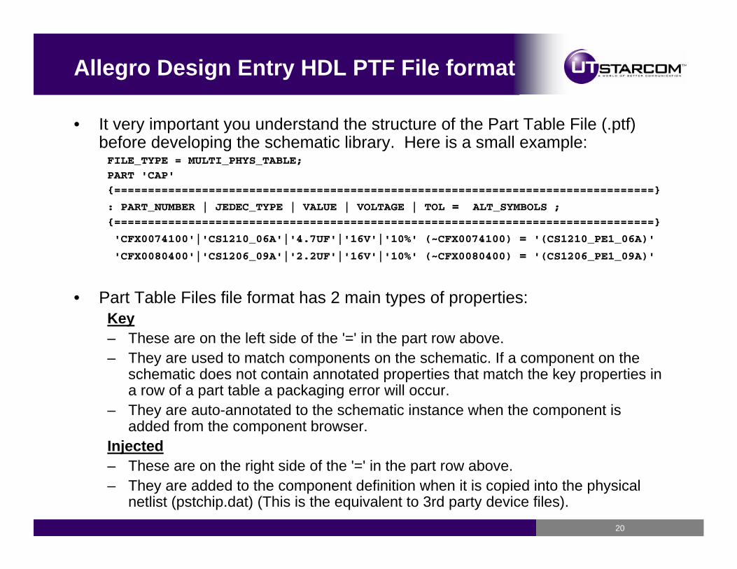
• It very important you understand the structure of the Part Table File (.ptf) before developing the schematic library. Here is a small example:FILE_TYPE = MULTI_PHYS_TABLE;
PART 'CAP'
{================================================================================}
: PART_NUMBER | JEDEC_TYPE | VALUE | VOLTAGE | TOL = ALT_SYMBOLS ;
{================================================================================}
'CFX0074100'|'CS1210_06A'|'4.7UF'|'16V'|'10%' (~CFX0074100) = '(CS1210_PE1_06A)'
'CFX0080400'|'CS1206_09A'|'2.2UF'|'16V'|'10%' (~CFX0080400) = '(CS1206_PE1_09A)'
• Part Table Files file format has 2 main types of properties: Key– These are on the left side of the '=' in the part row above.– They are used to match components on the schematic. If a component on the
schematic does not contain annotated properties that match the key properties in a row of a part table a packaging error will occur.
– They are auto-annotated to the schematic instance when the component is added from the component browser.
Injected– These are on the right side of the '=' in the part row above.– They are added to the component definition when it is copied into the physical
netlist (pstchip.dat) (This is the equivalent to 3rd party device files).
21
Allegro Design Entry HDL Attribute Passing
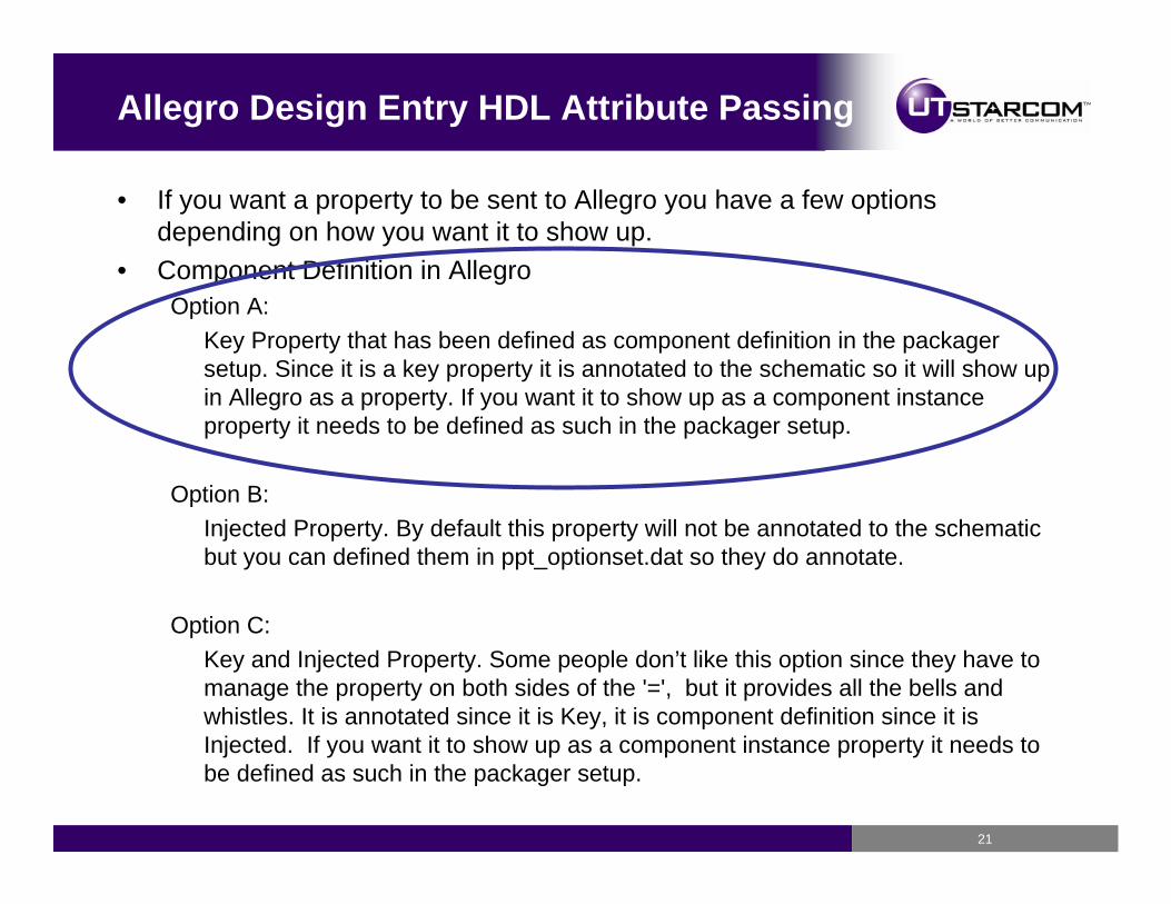
• If you want a property to be sent to Allegro you have a few options depending on how you want it to show up.
• Component Definition in AllegroOption A:
Key Property that has been defined as component definition in the packager setup. Since it is a key property it is annotated to the schematic so it will show up in Allegro as a property. If you want it to show up as a component instance property it needs to be defined as such in the packager setup.
Option B:Injected Property. By default this property will not be annotated to the schematic but you can defined them in ppt_optionset.dat so they do annotate.
Option C:Key and Injected Property. Some people don’t like this option since they have to manage the property on both sides of the '=', but it provides all the bells and whistles. It is annotated since it is Key, it is component definition since it is Injected. If you want it to show up as a component instance property it needs to be defined as such in the packager setup.
22
Pacakger-XL Configuration Updates
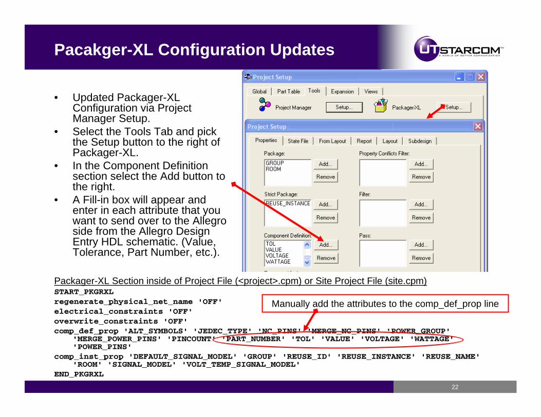
Packager-XL Section inside of Project File (<project>.cpm) or Site Project File (site.cpm)START_PKGRXLregenerate_physical_net_name 'OFF'electrical_constraints 'OFF'overwrite_constraints 'OFF'comp_def_prop 'ALT_SYMBOLS' 'JEDEC_TYPE' 'NC_PINS' 'MERGE_NC_PINS' 'POWER_GROUP'
'MERGE_POWER_PINS' 'PINCOUNT' 'PART_NUMBER' 'TOL' 'VALUE' 'VOLTAGE' 'WATTAGE' 'POWER_PINS'
comp_inst_prop 'DEFAULT_SIGNAL_MODEL' 'GROUP' 'REUSE_ID' 'REUSE_INSTANCE' 'REUSE_NAME' 'ROOM' 'SIGNAL_MODEL' 'VOLT_TEMP_SIGNAL_MODEL'
END_PKGRXL
Manually add the attributes to the comp_def_prop line
• Updated Packager-XL Configuration via Project Manager Setup.
• Select the Tools Tab and pick the Setup button to the right of Packager-XL.
• In the Component Definition section select the Add button to the right.
• A Fill-in box will appear and enter in each attribute that you want to send over to the Allegro side from the Allegro Design Entry HDL schematic. (Value, Tolerance, Part Number, etc.).
23
Part Table File – Explicit Device Type
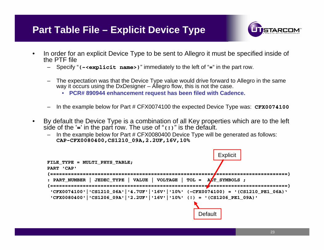
• In order for an explicit Device Type to be sent to Allegro it must be specified inside of the PTF file
– Specify “(~<explicit name>)” immediately to the left of “=“ in the part row.
– The expectation was that the Device Type value would drive forward to Allegro in the same way it occurs using the DxDesigner – Allegro flow, this is not the case.
• PCR# 890944 enhancement request has been filed with Cadence.
– In the example below for Part # CFX0074100 the expected Device Type was: CFX0074100
• By default the Device Type is a combination of all Key properties which are to the left side of the '=' in the part row. The use of “(!)” is the default.
– In the example below for Part # CFX0080400 Device Type will be generated as follows: CAP-CFX0080400,CS1210_09A,2.2UF,16V,10%
FILE_TYPE = MULTI_PHYS_TABLE;PART 'CAP'{================================================================================}: PART_NUMBER | JEDEC_TYPE | VALUE | VOLTAGE | TOL = ALT_SYMBOLS ;{================================================================================}'CFX0074100'|'CS1210_06A'|'4.7UF'|'16V'|'10%' (~CFX0074100) = '(CS1210_PE1_06A)‘'CFX0080400'|'CS1206_09A'|'2.2UF'|'16V'|'10%' (!) = '(CS1206_PE1_09A)'
Explicit
Default
24
Component Attributes – Lessons learned
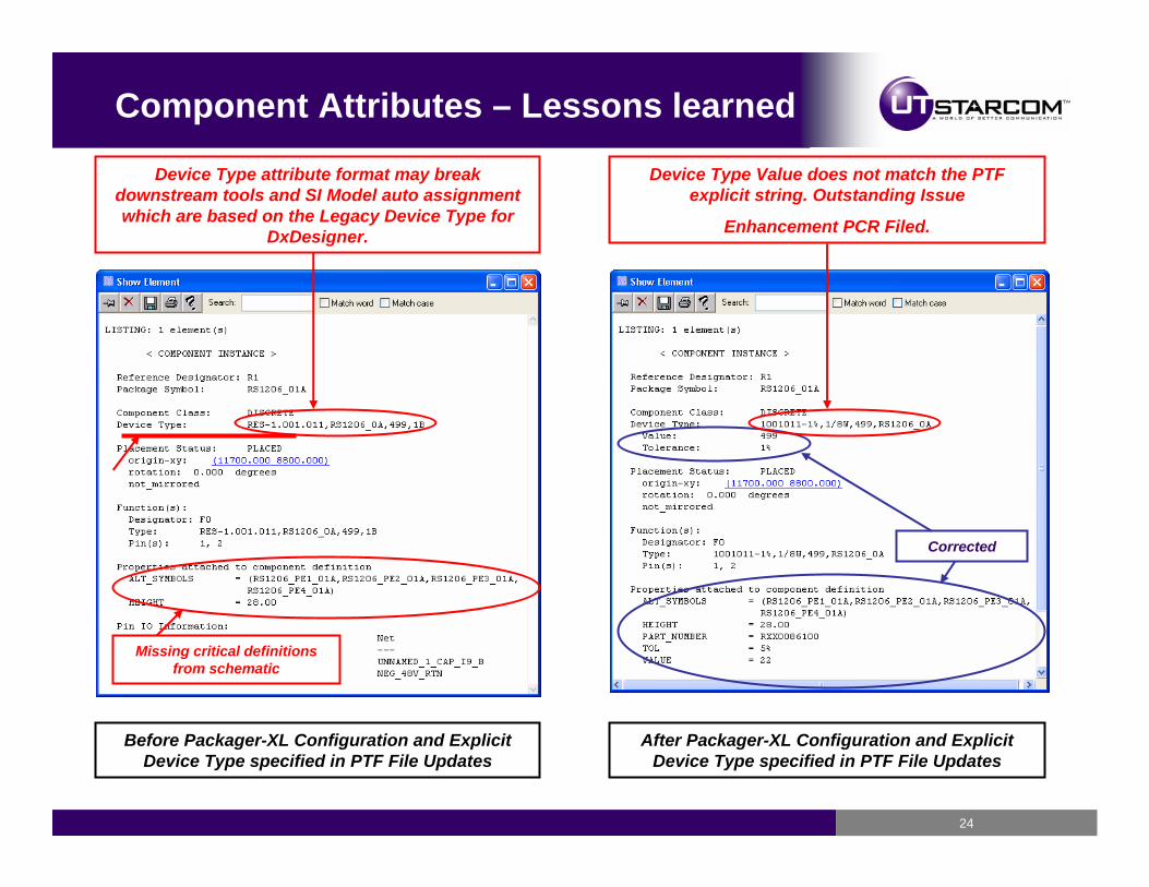
Missing critical definitions from schematic
Corrected
Before Packager-XL Configuration and Explicit Device Type specified in PTF File Updates
After Packager-XL Configuration and Explicit Device Type specified in PTF File Updates
Device Type Value does not match the PTF explicit string. Outstanding Issue
Enhancement PCR Filed.
Device Type attribute format may break downstream tools and SI Model auto assignment which are based on the Legacy Device Type for
DxDesigner.
25
DxDesginer HETERO Devices - Explained
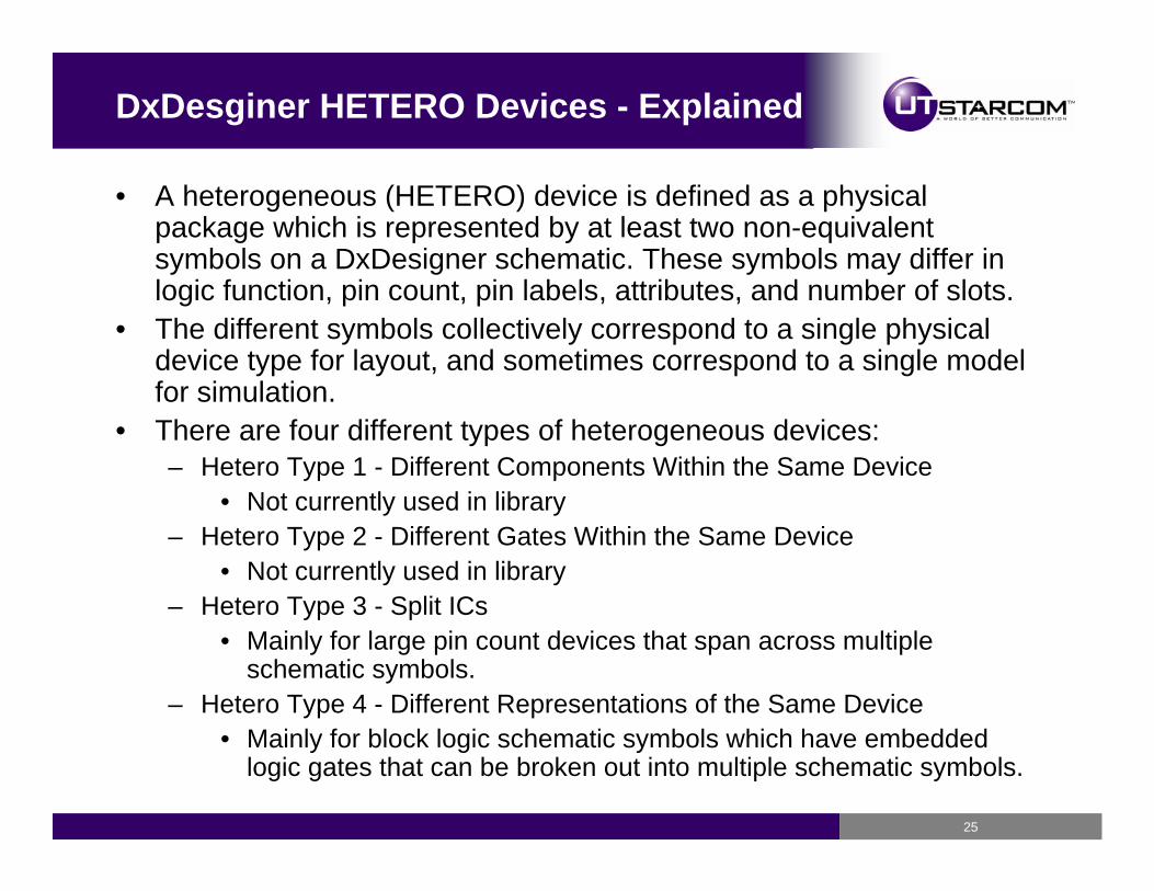
• A heterogeneous (HETERO) device is defined as a physical package which is represented by at least two non-equivalent symbols on a DxDesigner schematic. These symbols may differ in logic function, pin count, pin labels, attributes, and number of slots.
• The different symbols collectively correspond to a single physical device type for layout, and sometimes correspond to a single model for simulation.
• There are four different types of heterogeneous devices:– Hetero Type 1 - Different Components Within the Same Device
• Not currently used in library– Hetero Type 2 - Different Gates Within the Same Device
• Not currently used in library– Hetero Type 3 - Split ICs
• Mainly for large pin count devices that span across multiple schematic symbols.
– Hetero Type 4 - Different Representations of the Same Device• Mainly for block logic schematic symbols which have embedded
logic gates that can be broken out into multiple schematic symbols.
26
HETERO Type 3 – Migrated Successfully
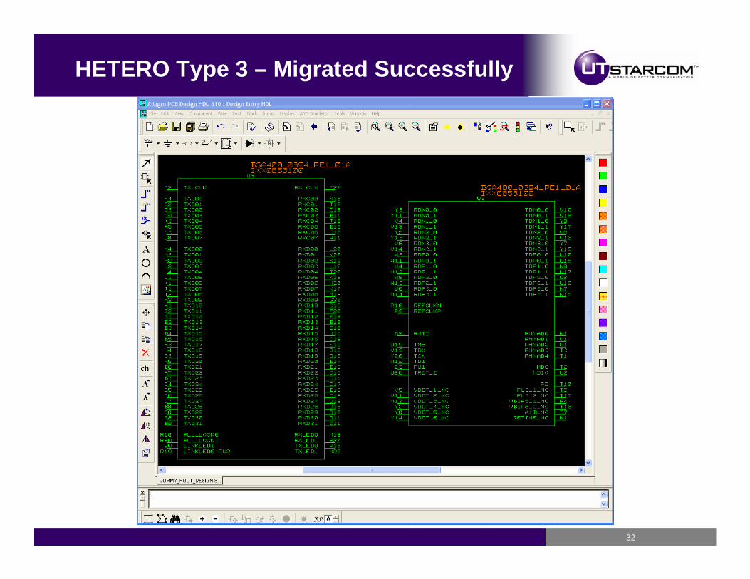
• HETERO Type 3 schematic symbols are used the most in our libraryto split large pin count devices across multiple schematic symbols.
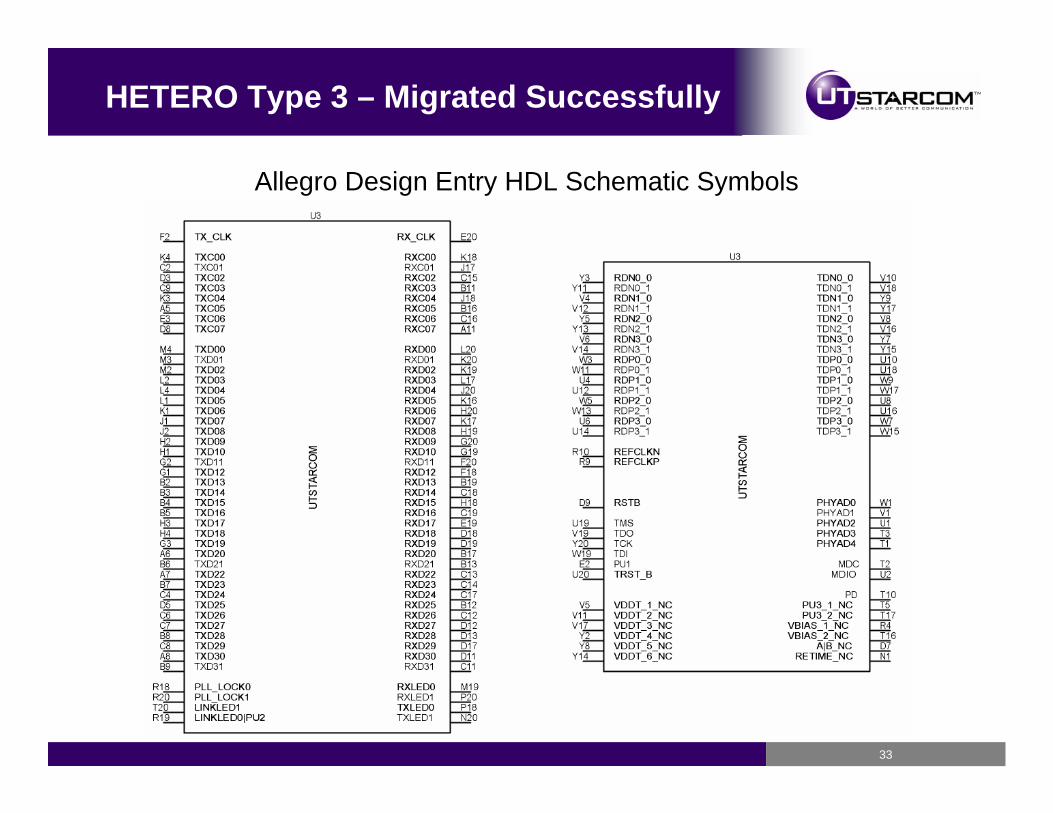
• Symbols pins are normally separated by function or intended use.• Amount of pins are also a factor on how many HETERO Symbols
are created for one particular device. (Symbol too large for sheet)• Package Power / Ground Pins and NC Pins can sometimes be very
hard to handle so they can also be grouped in separate symbols as required.
• Attribute SyntaxHETERO = (UCHDC123_H1_02), (UCHDC123_H2_02)
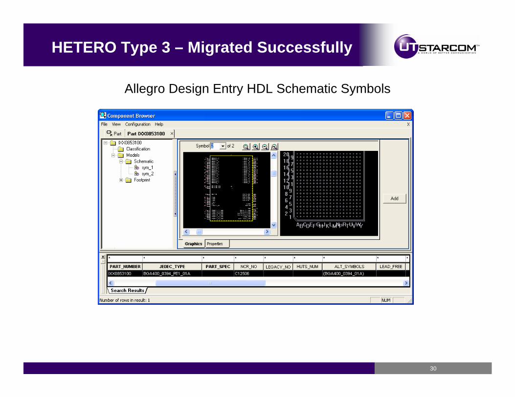
• No issues found ☺ Migrated over to Allegro Design Entry HDL library without error; All symbols referenced in HETERO Attribute merged into one Chips.prt file and the user can simply select the different schematic symbols from the component browser.
27
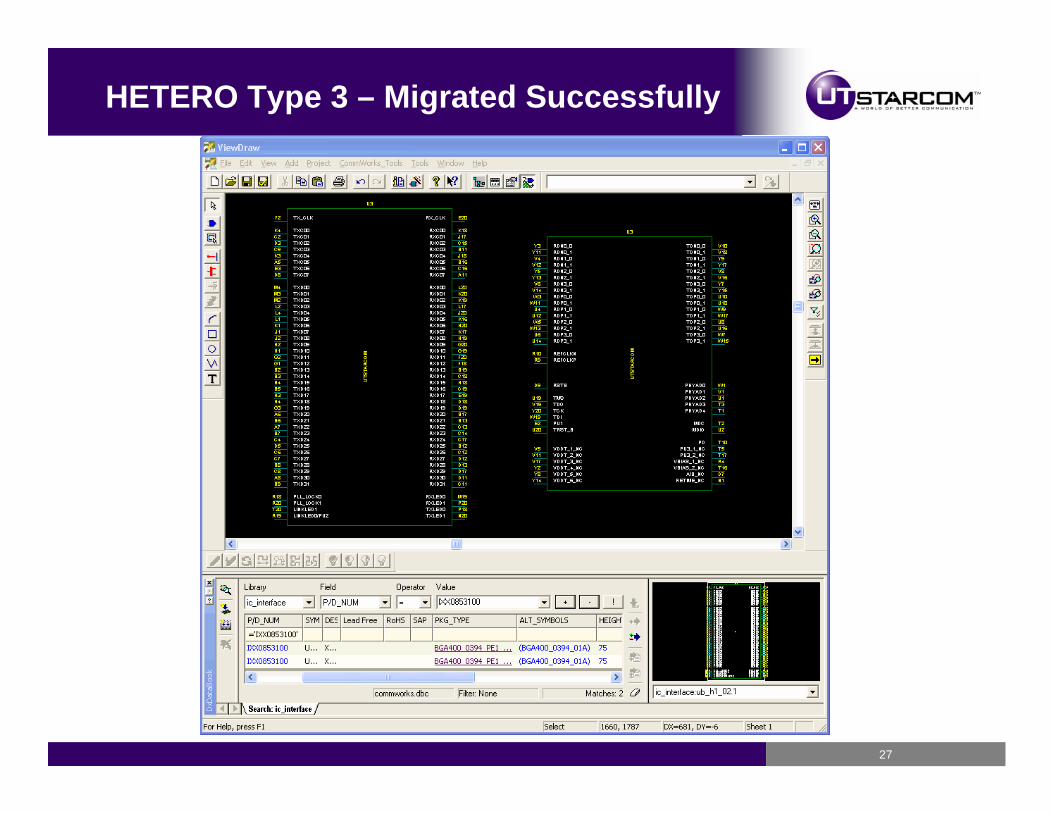
HETERO Type 3 – Migrated Successfully
28
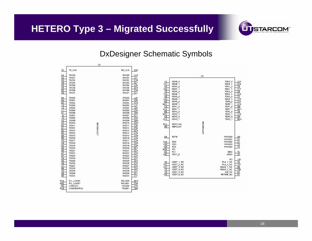
HETERO Type 3 – Migrated Successfully
DxDesigner Schematic Symbols

29
HETERO Type 3 – Migrated Successfully
Allegro Design Entry HDL Schematic Symbols
30
HETERO Type 3 – Migrated Successfully
Allegro Design Entry HDL Schematic Symbols
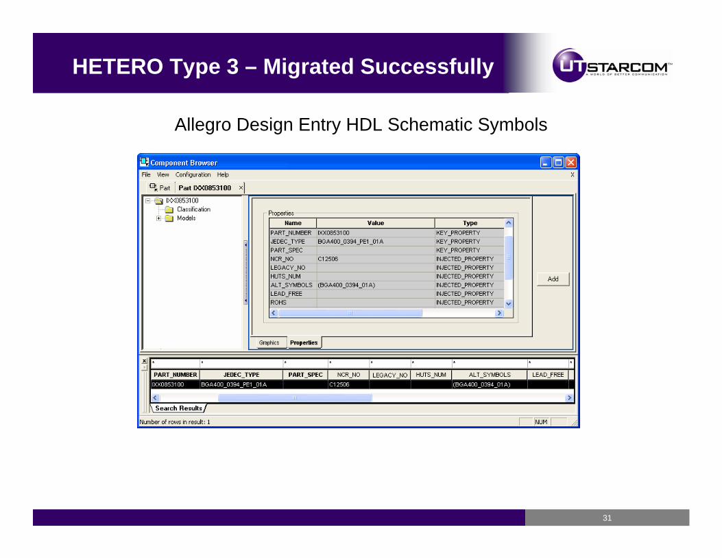
31
HETERO Type 3 – Migrated Successfully
Allegro Design Entry HDL Schematic Symbols
32
HETERO Type 3 – Migrated Successfully
33
HETERO Type 3 – Migrated Successfully
Allegro Design Entry HDL Schematic Symbols
34
HETERO Type 4 – Migration Issues
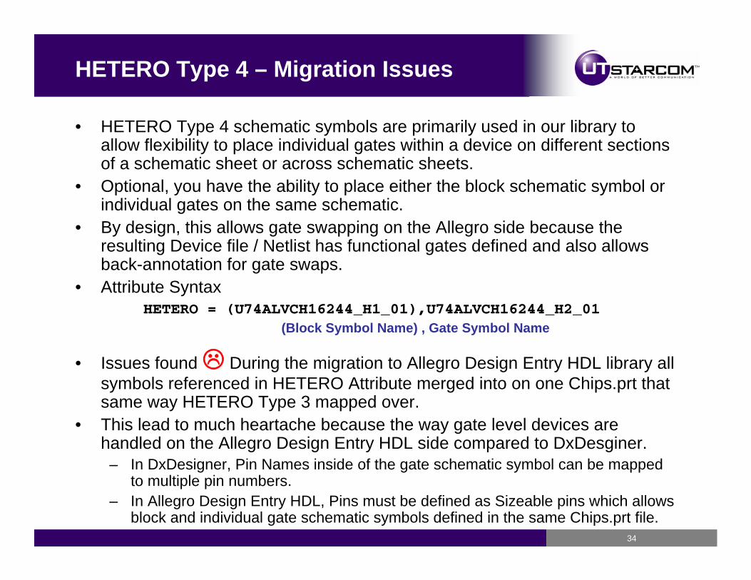
• HETERO Type 4 schematic symbols are primarily used in our library to allow flexibility to place individual gates within a device on different sections of a schematic sheet or across schematic sheets.
• Optional, you have the ability to place either the block schematic symbol or individual gates on the same schematic.
• By design, this allows gate swapping on the Allegro side because the resulting Device file / Netlist has functional gates defined and also allows back-annotation for gate swaps.
• Attribute SyntaxHETERO = (U74ALVCH16244_H1_01),U74ALVCH16244_H2_01
• Issues found During the migration to Allegro Design Entry HDL library all symbols referenced in HETERO Attribute merged into on one Chips.prt that same way HETERO Type 3 mapped over.
• This lead to much heartache because the way gate level devices are handled on the Allegro Design Entry HDL side compared to DxDesginer.
– In DxDesigner, Pin Names inside of the gate schematic symbol can be mapped to multiple pin numbers.
– In Allegro Design Entry HDL, Pins must be defined as Sizeable pins which allows block and individual gate schematic symbols defined in the same Chips.prt file.
(Block Symbol Name) , Gate Symbol Name

35
HETERO Type 4 – Migration Issues
• DxDesigner HETERO 4 Example:HETERO = (U74ALVCH16244_H1_01),U74ALVCH16244_H2_01
U74ALVCH16244_H1_01 U74ALVCH16244_H2_01
36
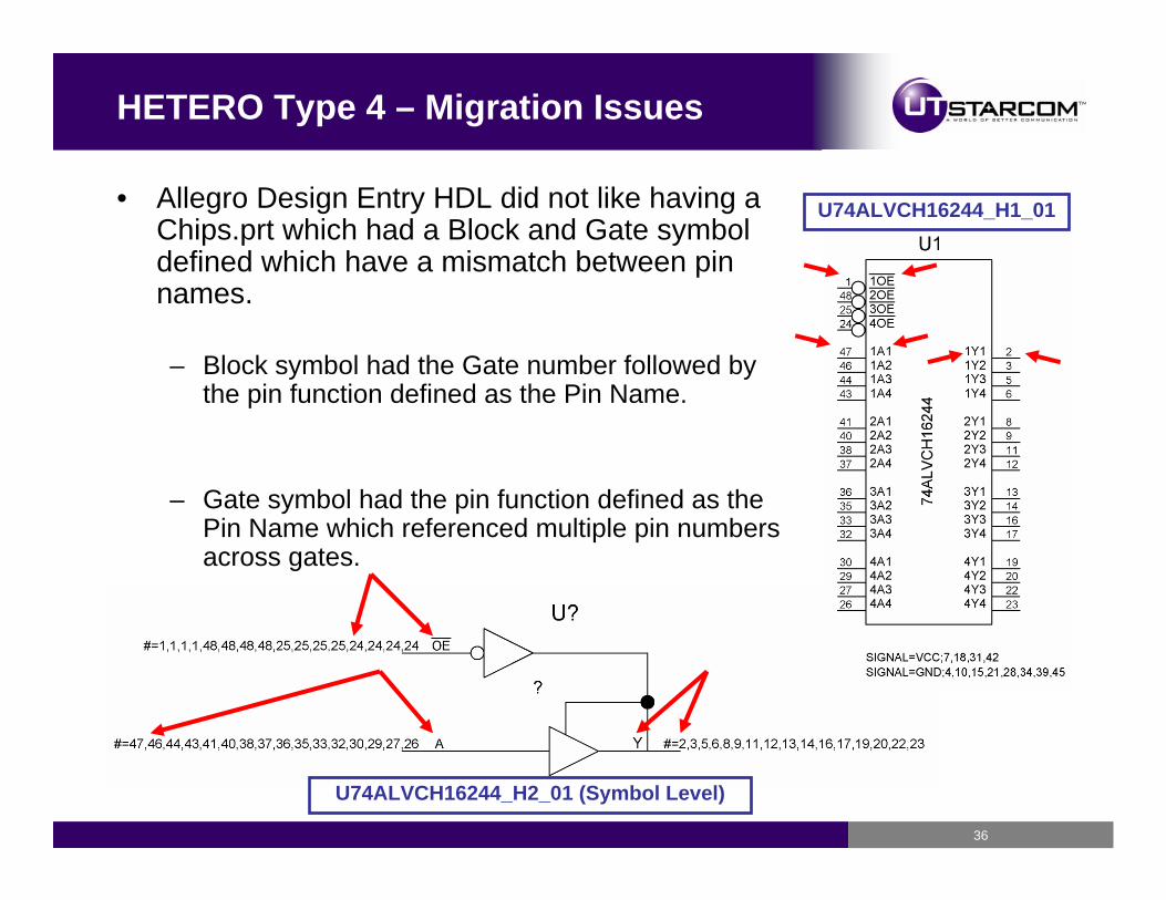
HETERO Type 4 – Migration Issues
• Allegro Design Entry HDL did not like having a Chips.prt which had a Block and Gate symbol defined which have a mismatch between pin names.
– Block symbol had the Gate number followed by the pin function defined as the Pin Name.
– Gate symbol had the pin function defined as the Pin Name which referenced multiple pin numbers across gates.
U74ALVCH16244_H2_01 (Symbol Level)
U74ALVCH16244_H1_01
37
HETERO Type 4 – Migration Issues
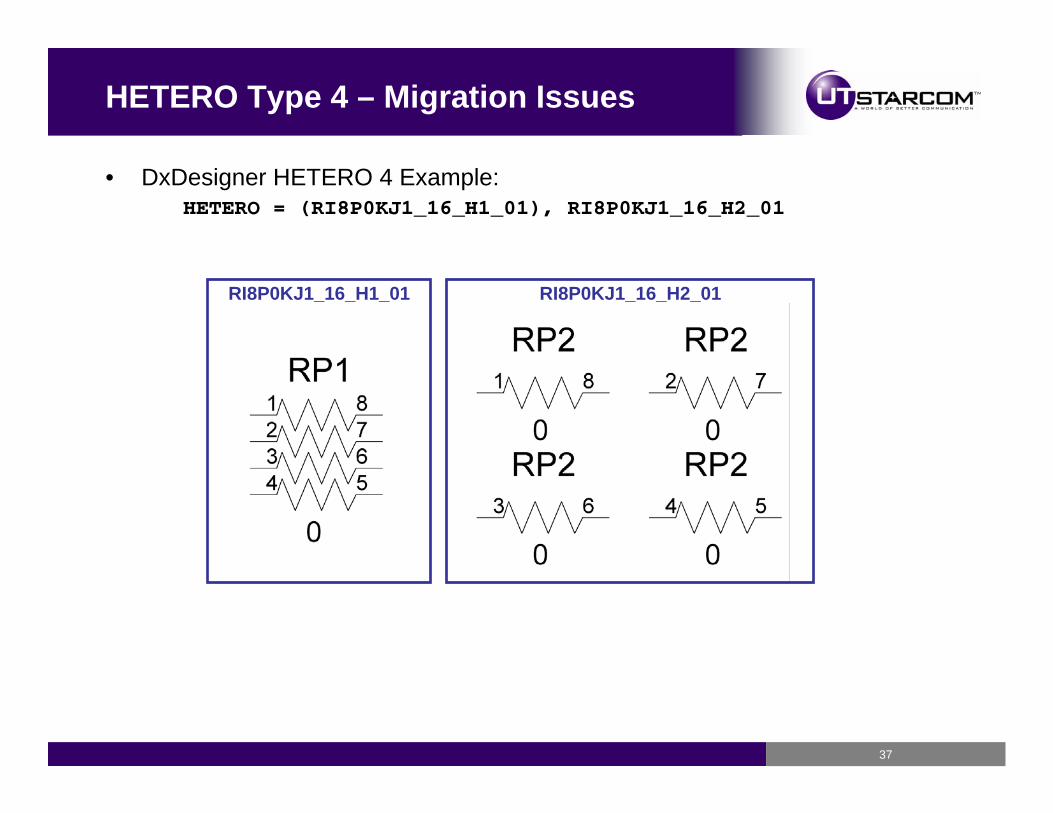
• DxDesigner HETERO 4 Example:HETERO = (RI8P0KJ1_16_H1_01), RI8P0KJ1_16_H2_01
RI8P0KJ1_16_H1_01 RI8P0KJ1_16_H2_01
38
HETERO Type 4 – Migration Issues
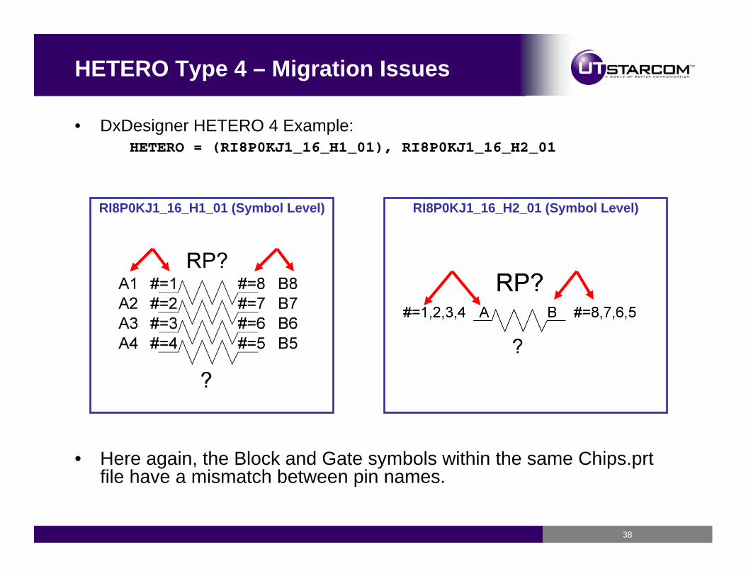
• DxDesigner HETERO 4 Example:HETERO = (RI8P0KJ1_16_H1_01), RI8P0KJ1_16_H2_01
RI8P0KJ1_16_H1_01 (Symbol Level) RI8P0KJ1_16_H2_01 (Symbol Level)
• Here again, the Block and Gate symbols within the same Chips.prtfile have a mismatch between pin names.
39
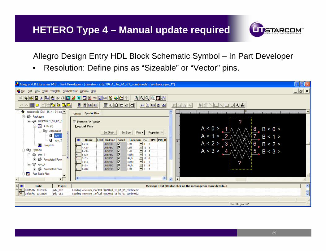
HETERO Type 4 – Manual update required
Allegro Design Entry HDL Block Schematic Symbol – In Part Developer• Resolution: Define pins as “Sizeable” or “Vector” pins.
40
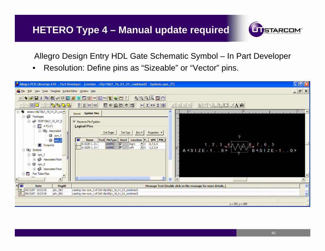
HETERO Type 4 – Manual update required
Allegro Design Entry HDL Gate Schematic Symbol – In Part Developer• Resolution: Define pins as “Sizeable” or “Vector” pins.
41
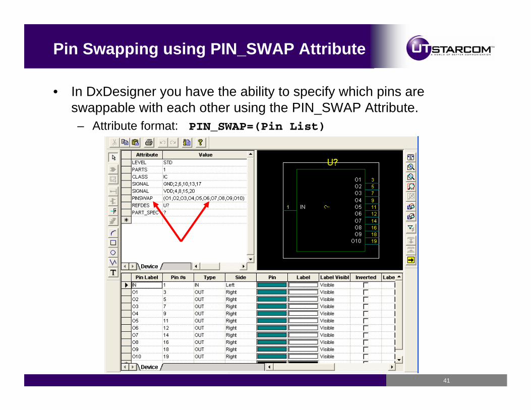
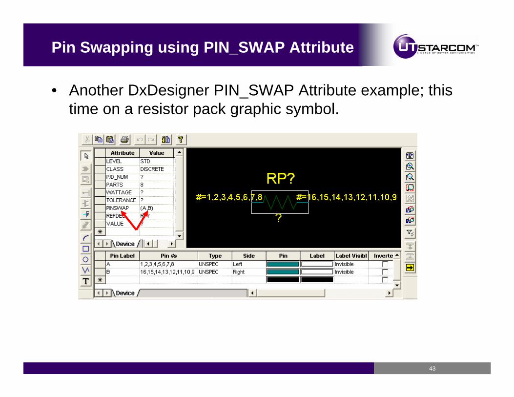
Pin Swapping using PIN_SWAP Attribute
• In DxDesigner you have the ability to specify which pins are swappable with each other using the PIN_SWAP Attribute.– Attribute format: PIN_SWAP=(Pin List)
42
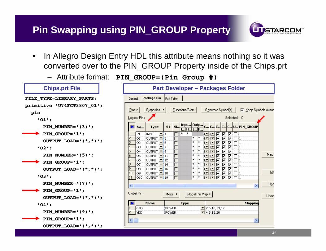
Pin Swapping using PIN_GROUP Property
• In Allegro Design Entry HDL this attribute means nothing so it was converted over to the PIN_GROUP Property inside of the Chips.prt– Attribute format: PIN_GROUP=(Pin Group #)
FILE_TYPE=LIBRARY_PARTS;
primitive 'U74FCT3807_01';
pin
'O1':
PIN_NUMBER='(3)';
PIN_GROUP='1';
OUTPUT_LOAD='(*,*)';
'O2':
PIN_NUMBER='(5)';
PIN_GROUP='1';
OUTPUT_LOAD='(*,*)';
'O3':
PIN_NUMBER='(7)';
PIN_GROUP='1';
OUTPUT_LOAD='(*,*)';
'O4':
PIN_NUMBER='(9)';
PIN_GROUP='1';
OUTPUT_LOAD='(*,*)';
Chips.prt File Part Developer – Packages Folder
43
Pin Swapping using PIN_SWAP Attribute
• Another DxDesigner PIN_SWAP Attribute example; this time on a resistor pack graphic symbol.
44
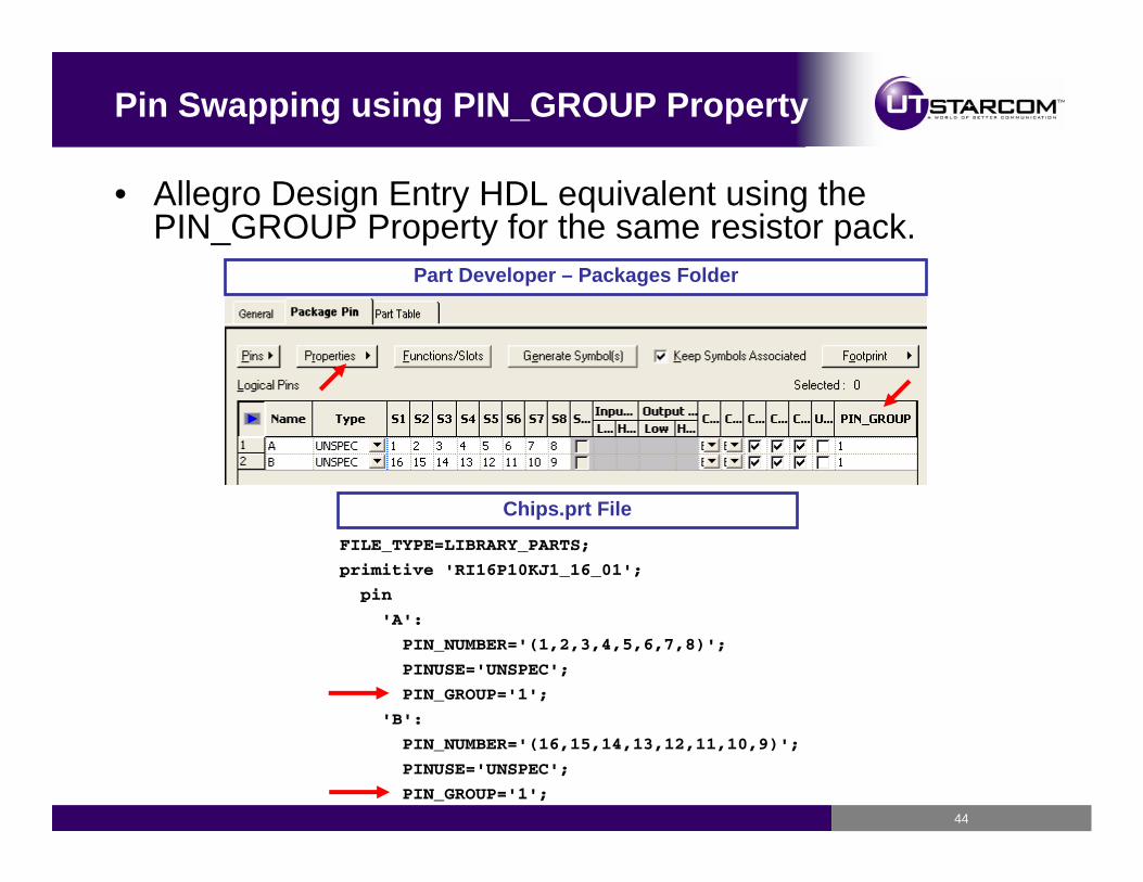
Pin Swapping using PIN_GROUP Property
• Allegro Design Entry HDL equivalent using the PIN_GROUP Property for the same resistor pack.
FILE_TYPE=LIBRARY_PARTS;
primitive 'RI16P10KJ1_16_01';
pin
'A':
PIN_NUMBER='(1,2,3,4,5,6,7,8)';
PINUSE='UNSPEC';
PIN_GROUP='1';
'B':
PIN_NUMBER='(16,15,14,13,12,11,10,9)';
PINUSE='UNSPEC';
PIN_GROUP='1';
Chips.prt File
Part Developer – Packages Folder
45
Conclusion
• Our DxDatabook Library has been successfully migrated over to Allegro Design Entry HDL and is currently in use today.
– We managed to transition 98% of the DxDatabook library over to Allegro Design Entry HDL with the 2% related to functionality differences between the two tools.
• The first stage of the transition focused on about 120 unique part numbers from a select group of common reuse sections between two of our major projects.
– This effort took about two weeks to complete with most of the time being spent on automation setup and attribute mapping.
• The final stage of the transition focused on the entire library as a whole and with all the automation in place we had the ability to make running changes then regenerate the library.
– This effort took about ten weeks of transition time which included intense verification on both sides.
– Most effort was spent on the HETERO mapping and troubleshooting.
• Savings from outsourcing– We estimated that to rebuild the library manually it would have taken about 1 ½
years even with multiple dedicated resources.– We saved about 1 year of time as well as costs of additional resources for
generation and verification.
46