710 Ultrasonic Module Installation and Operation Guide Part #60-9003-062 Copyright © 1995, 2003. All rights reserved, Isco, Inc. Revision G, October 2013

Welcome message from author
This document is posted to help you gain knowledge. Please leave a comment to let me know what you think about it! Share it to your friends and learn new things together.
Transcript
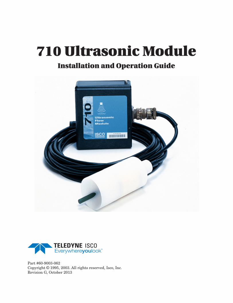
710 Ultrasonic ModuleInstallation and Operation Guide
Part #60-9003-062Copyright © 1995, 2003. All rights reserved, Isco, Inc.Revision G, October 2013

Foreword
This instruction manual is designed to help you gain a thorough understanding of the operation ofthe equipment. Teledyne Isco recommends that you read this manual completely before placing theequipment in service.
Although Teledyne Isco designs reliability into all equipment, there is always the possibility of amalfunction. This manual may help in diagnosing and repairing the malfunction.
If a problem persists, call or e-mail the Teledyne Isco Technical Service Department for assistance.Simple difficulties can often be diagnosed over the phone.
If it is necessary to return the equipment to the factory for service, please follow the shippinginstructions provided by the Customer Service Department, including the use of the ReturnAuthorization Number specified. Be sure to include a note describing the malfunction. Thiswill aid in the prompt repair and return of the equipment.
Teledyne Isco welcomes suggestions that would improve the information presented in this manualor enhance the operation of the equipment itself.
Teledyne Isco is continually improving its products and reserves the right to change productspecifications, replacement parts, schematics, and instructions without notice.
Contact Information
Customer Service
Phone: (800) 228-4373 (USA, Canada, Mexico)
(402) 464-0231 (Outside North America)
Fax: (402) 465-3022
Email: [email protected]
Technical Support
Phone: Toll Free (866) 298-6174 (Samplers and Flow Meters)
Toll Free (800) 775-2965 (Syringe Pumps and Liquid Chromatography)
Email: [email protected]
Return equipment to: 4700 Superior Street, Lincoln, NE 68504-1398
Other Correspondence
Mail to: P.O. Box 82531, Lincoln, NE 68501-2531
Email: [email protected]
Revised September 2012

710 Ultrasonic ModuleSafety
iii
710 Ultrasonic ModuleSafety
General Warnings This product is often installed in confined spaces. Some examplesof confined spaces are manholes, pipelines, digesters, and storagetanks. These spaces may become hazardous environments thatcan prove fatal for those unprepared. These spaces are governedby OSHA 1910.146 and require a permit before entering.
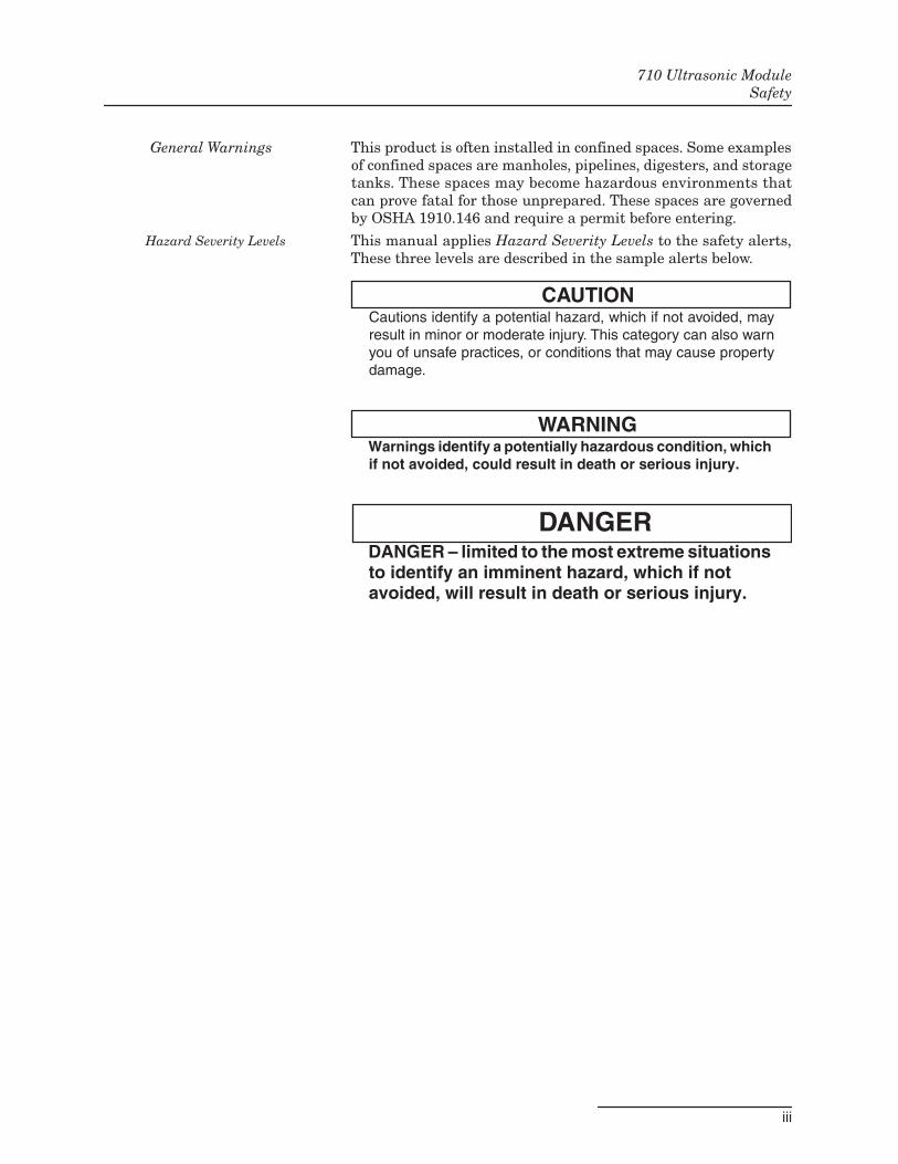
Hazard Severity Levels This manual applies Hazard Severity Levels to the safety alerts,These three levels are described in the sample alerts below.
CAUTIONCautions identify a potential hazard, which if not avoided, mayresult in minor or moderate injury. This category can also warnyou of unsafe practices, or conditions that may cause propertydamage.
WARNINGWarnings identify a potentially hazardous condition, whichif not avoided, could result in death or serious injury.
DANGERDANGER – limited to the most extreme situationsto identify an imminent hazard, which if notavoided, will result in death or serious injury.
710 Ultrasonic ModuleSafety
iv
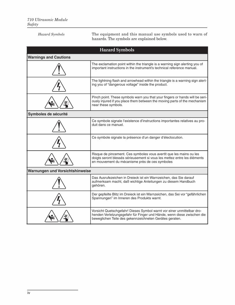
Hazard Symbols The equipment and this manual use symbols used to warn ofhazards. The symbols are explained below.
Hazard Symbols
Warnings and Cautions
The exclamation point within the triangle is a warning sign alerting you ofimportant instructions in the instrument’s technical reference manual.
The lightning flash and arrowhead within the triangle is a warning sign alert-ing you of “dangerous voltage” inside the product.
Pinch point. These symbols warn you that your fingers or hands will be seri-ously injured if you place them between the moving parts of the mechanismnear these symbols.
Symboles de sécurité
Ce symbole signale l’existence d’instructions importantes relatives au pro-duit dans ce manuel.
Ce symbole signale la présence d’un danger d’électocution.
Risque de pincement. Ces symboles vous avertit que les mains ou lesdoigts seront blessés sérieusement si vous les mettez entre les élémentsen mouvement du mécanisme près de ces symboles
Warnungen und Vorsichtshinweise
Das Ausrufezeichen in Dreieck ist ein Warnzeichen, das Sie daraufaufmerksam macht, daß wichtige Anleitungen zu diesem Handbuchgehören.
Der gepfeilte Blitz im Dreieck ist ein Warnzeichen, das Sei vor “gefährlichenSpannungen” im Inneren des Produkts warnt.
Vorsicht Quetschgefahr! Dieses Symbol warnt vor einer unmittelbar dro-henden Verletzungsgefahr für Finger und Hände, wenn diese zwischen diebeweglichen Teile des gekennzeichneten Gerätes geraten.
vii
710 Ultrasonic Module
Table of Contents
Section 1 Installation and Programming
1.1 Introduction . . . . . . . . . . . . . . . . . . . . . . . . . . . . . . . . . . . . . . . . . . . . . . . . . . . . . . . . 1-11.1.1 Installing the Module . . . . . . . . . . . . . . . . . . . . . . . . . . . . . . . . . . . . . . . . . . 1-11.1.2 Installation Checklist . . . . . . . . . . . . . . . . . . . . . . . . . . . . . . . . . . . . . . . . . . 1-2
1.2 Programming Notes . . . . . . . . . . . . . . . . . . . . . . . . . . . . . . . . . . . . . . . . . . . . . . . . . 1-21.2.1 Programmed Enable . . . . . . . . . . . . . . . . . . . . . . . . . . . . . . . . . . . . . . . . . . . 1-3
1.3 Mounting the Ultrasonic Level Sensor . . . . . . . . . . . . . . . . . . . . . . . . . . . . . . . . . . 1-71.3.1 User-Determined Mounting Location . . . . . . . . . . . . . . . . . . . . . . . . . . . . . . 1-81.3.2 Dead Band . . . . . . . . . . . . . . . . . . . . . . . . . . . . . . . . . . . . . . . . . . . . . . . . . . . 1-81.3.3 Accidental Submersion . . . . . . . . . . . . . . . . . . . . . . . . . . . . . . . . . . . . . . . . 1-10
1.4 Mounting the Sensor . . . . . . . . . . . . . . . . . . . . . . . . . . . . . . . . . . . . . . . . . . . . . . . . 1-101.4.1 Use a Level . . . . . . . . . . . . . . . . . . . . . . . . . . . . . . . . . . . . . . . . . . . . . . . . . . 1-101.4.2 Remove the Protector Cap . . . . . . . . . . . . . . . . . . . . . . . . . . . . . . . . . . . . . . 1-10
1.5 Maintenance . . . . . . . . . . . . . . . . . . . . . . . . . . . . . . . . . . . . . . . . . . . . . . . . . . . . . . 1-131.6 How to Get Help . . . . . . . . . . . . . . . . . . . . . . . . . . . . . . . . . . . . . . . . . . . . . . . . . . . 1-131.7 Flash Memory and Software Upgrades . . . . . . . . . . . . . . . . . . . . . . . . . . . . . . . . . 1-131.8 Technical Specifications . . . . . . . . . . . . . . . . . . . . . . . . . . . . . . . . . . . . . . . . . . . . . 1-14
Section 2 The Ultrasonic Level Sensor
2.1 Description. . . . . . . . . . . . . . . . . . . . . . . . . . . . . . . . . . . . . . . . . . . . . . . . . . . . . . . . . 2-12.2 Transducer Operation . . . . . . . . . . . . . . . . . . . . . . . . . . . . . . . . . . . . . . . . . . . . . . . . 2-1
2.2.1 Validity Tests . . . . . . . . . . . . . . . . . . . . . . . . . . . . . . . . . . . . . . . . . . . . . . . . . 2-12.2.2 Ambient Air Temperature Factor . . . . . . . . . . . . . . . . . . . . . . . . . . . . . . . . . 2-12.2.3 Return Echo Amplifier Compensation . . . . . . . . . . . . . . . . . . . . . . . . . . . . . 2-1
2.3 Error Factors and Module Compensation . . . . . . . . . . . . . . . . . . . . . . . . . . . . . . . . 2-32.3.1 Velocity Errors . . . . . . . . . . . . . . . . . . . . . . . . . . . . . . . . . . . . . . . . . . . . . . . . 2-32.3.2 Echo Detect Errors . . . . . . . . . . . . . . . . . . . . . . . . . . . . . . . . . . . . . . . . . . . . . 2-32.3.3 Beam Angle . . . . . . . . . . . . . . . . . . . . . . . . . . . . . . . . . . . . . . . . . . . . . . . . . . 2-32.3.4 Noise . . . . . . . . . . . . . . . . . . . . . . . . . . . . . . . . . . . . . . . . . . . . . . . . . . . . . . . . 2-32.3.5 Surface Objects . . . . . . . . . . . . . . . . . . . . . . . . . . . . . . . . . . . . . . . . . . . . . . . 2-32.3.6 Temperature . . . . . . . . . . . . . . . . . . . . . . . . . . . . . . . . . . . . . . . . . . . . . . . . . . 2-42.3.7 Waves . . . . . . . . . . . . . . . . . . . . . . . . . . . . . . . . . . . . . . . . . . . . . . . . . . . . . . . 2-42.3.8 Wavelength . . . . . . . . . . . . . . . . . . . . . . . . . . . . . . . . . . . . . . . . . . . . . . . . . . . 2-42.3.9 Wind . . . . . . . . . . . . . . . . . . . . . . . . . . . . . . . . . . . . . . . . . . . . . . . . . . . . . . . . 2-42.3.10 Other Factors . . . . . . . . . . . . . . . . . . . . . . . . . . . . . . . . . . . . . . . . . . . . . . . . 2-4
2.4 Minimizing Level Measurement Errors. . . . . . . . . . . . . . . . . . . . . . . . . . . . . . . . . . 2-52.4.1 Temperature Differences . . . . . . . . . . . . . . . . . . . . . . . . . . . . . . . . . . . . . . . . 2-52.4.2 Avoid Wind . . . . . . . . . . . . . . . . . . . . . . . . . . . . . . . . . . . . . . . . . . . . . . . . . . . 2-52.4.3 Excessive Distance . . . . . . . . . . . . . . . . . . . . . . . . . . . . . . . . . . . . . . . . . . . . . 2-52.4.4 Calibration Temperature . . . . . . . . . . . . . . . . . . . . . . . . . . . . . . . . . . . . . . . . 2-62.4.5 Water Condensation . . . . . . . . . . . . . . . . . . . . . . . . . . . . . . . . . . . . . . . . . . . 2-62.4.6 Foam, Oil, and Turbulence . . . . . . . . . . . . . . . . . . . . . . . . . . . . . . . . . . . . . . 2-62.4.7 Small Pipes and Channels . . . . . . . . . . . . . . . . . . . . . . . . . . . . . . . . . . . . . . . 2-72.4.8 Alternative Flow Measurement Systems . . . . . . . . . . . . . . . . . . . . . . . . . . . 2-8
Appendix A Accessories
710 Ultrasonic ModuleTable of Contents
viii
List of Figures1-1 710 Module Installed on Sampler . . . . . . . . . . . . . . . . . . . . . . . . . . . . . . . . . . . . . . 1-21-2 6712 Programming: 710 Module Screens . . . . . . . . . . . . . . . . . . . . . . . . . . . . . . . . 1-41-3 6712 Programming: 710 Module Setup Screens . . . . . . . . . . . . . . . . . . . . . . . . . . . 1-51-4 6712 Programming: 710 Quick View Screens . . . . . . . . . . . . . . . . . . . . . . . . . . . . . 1-61-5 Ultrasonic Level Sensor Dead Band . . . . . . . . . . . . . . . . . . . . . . . . . . . . . . . . . . . . 1-81-6 Level Change, Temperature, and Calibration Factors . . . . . . . . . . . . . . . . . . . . . . 1-91-7 Mounting the Ultrasonic Level Sensor . . . . . . . . . . . . . . . . . . . . . . . . . . . . . . . . . 1-111-8 Mounting the Ultrasonic Level Sensor (Continued) . . . . . . . . . . . . . . . . . . . . . . . 1-122-1 Ultrasonic Level Sensor Operation . . . . . . . . . . . . . . . . . . . . . . . . . . . . . . . . . . . . . 2-22-2 Foam and Oil on the Surface of the Flow Stream . . . . . . . . . . . . . . . . . . . . . . . . . 2-62-3 Small Pipes and Narrow Channels . . . . . . . . . . . . . . . . . . . . . . . . . . . . . . . . . . . . . 2-7
List of Tables1-1 Flow Conversion Methods . . . . . . . . . . . . . . . . . . . . . . . . . . . . . . . . . . . . . . . . . . . . 1-71-2 Technical Specifications for the 710 Module . . . . . . . . . . . . . . . . . . . . . . . . . . . . . 1-14
1-1
710 Ultrasonic Module
Section 1 Installation and Programming
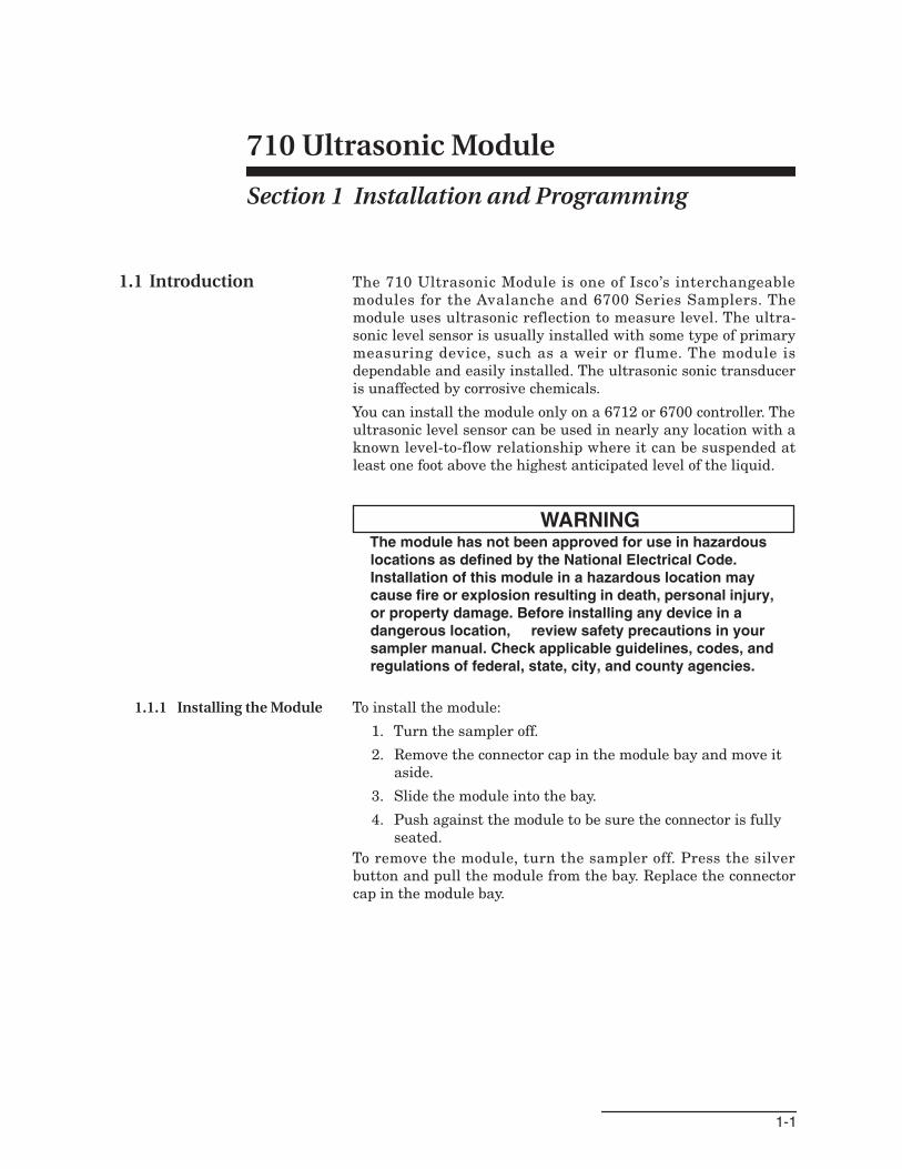
1.1 Introduction The 710 Ultrasonic Module is one of Isco’s interchangeablemodules for the Avalanche and 6700 Series Samplers. Themodule uses ultrasonic reflection to measure level. The ultra-sonic level sensor is usually installed with some type of primarymeasuring device, such as a weir or flume. The module isdependable and easily installed. The ultrasonic sonic transduceris unaffected by corrosive chemicals.
You can install the module only on a 6712 or 6700 controller. Theultrasonic level sensor can be used in nearly any location with aknown level-to-flow relationship where it can be suspended atleast one foot above the highest anticipated level of the liquid.
WARNINGThe module has not been approved for use in hazardouslocations as defined by the National Electrical Code.Installation of this module in a hazardous location maycause fire or explosion resulting in death, personal injury,or property damage. Before installing any device in adangerous location, review safety precautions in yoursampler manual. Check applicable guidelines, codes, andregulations of federal, state, city, and county agencies.
1.1.1 Installing the Module To install the module:
1. Turn the sampler off.
2. Remove the connector cap in the module bay and move itaside.
3. Slide the module into the bay.
4. Push against the module to be sure the connector is fullyseated.
To remove the module, turn the sampler off. Press the silverbutton and pull the module from the bay. Replace the connectorcap in the module bay.
710 Ultrasonic ModuleSection 1 Installation and Programming
1-2
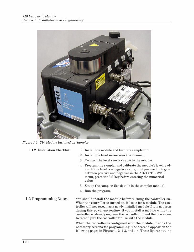
Figure 1-1 710 Module Installed on Sampler
1.1.2 Installation Checklist 1. Install the module and turn the sampler on.
2. Install the level sensor over the channel.
3. Connect the level sensor’s cable to the module.
4. Program the sampler and calibrate the module’s level read-ing. If the level is a negative value, or if you need to togglebetween positive and negative in the ADJUST LEVELmenu, press the "±" key before entering the numericalvalue.
5. Set up the sampler. See details in the sampler manual.
6. Run the program.
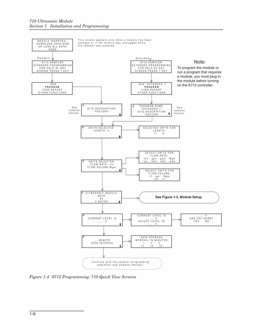
1.2 Programming Notes You should install the module before turning the controller on.When the controller is turned on, it looks for a module. The con-troller will not recognize a newly installed module if it is not seenduring this power-up routine. If you install a module while thecontroller is already on, turn the controller off and then on againto reconfigure the controller for use with the module.
When the controller is configured with the module, it adds thenecessary screens for programming. The screens appear on thefollowing pages in Figures 1-2, 1-3, and 1-4. These figures outline
710 Ultrasonic ModuleSection 1 Installation and Programming
1-3
the steps for module programming and calibration. For 6712 pro-gramming and general programming information, see thesampler manual.
An asterisk (*) appears next to a reading if the module wasunable to take a reading. If an asterisk appears, the reading dis-played is the last available reading.
1.2.1 Programmed Enable When a 710 Module is installed, additional sampler enableoptions are available. If programmed for LEVEL ONLY, theadditional option is LEVEL. If programmed for FLOW METER,the additional options will be LEVEL and FLOW. For more infor-mation about programmed enables, see the sampler manual.
710 Ultrasonic ModuleSection 1 Installation and Programming
1-4
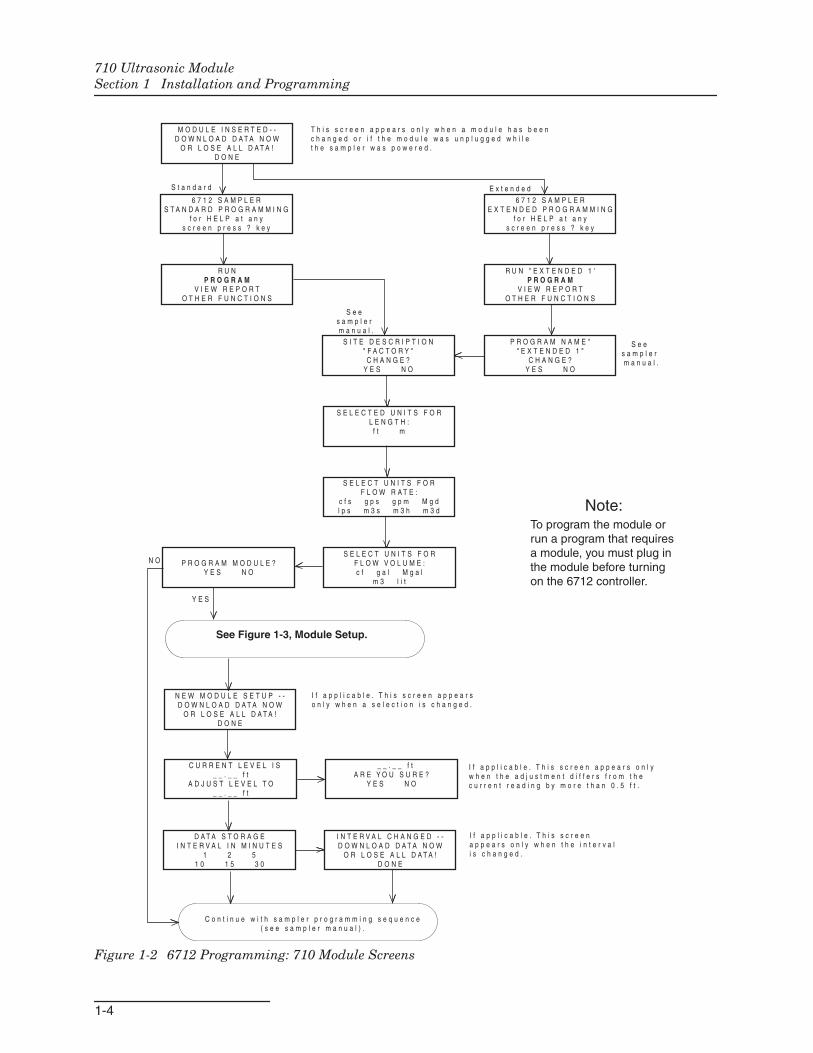
Figure 1-2 6712 Programming: 710 Module Screens
S E L E C T U N I T S F O RF L O W V O L U M E :c f g a l M g a l
m 3 l i t
6 7 1 2 S A M P L E RE X T E N D E D P R O G R A M M I N G
f o r H E L P a t a n ys c r e e n p r e s s ? k e y
R U NP R O G R A M
V I E W R E P O R TO T H E R F U N C T I O N S
M O D U L E I N S E R T E D - -D O W N L O A D D A T A N O W
O R L O S E A L L D A T A !D O N E
6 7 1 2 S A M P L E RS T A N D A R D P R O G R A M M I N G
f o r H E L P a t a n ys c r e e n p r e s s ? k e y
S I T E D E S C R I P T I O N" F A C T O R Y "C H A N G E ?
Y E S N O
S E L E C T U N I T S F O RF L O W R A T E :
c f s g p s g p m M g dl p s m 3 s m 3 h m 3 d
R U N " E X T E N D E D 1 'P R O G R A M
V I E W R E P O R TO T H E R F U N C T I O N S
P R O G R A M N A M E "" E X T E N D E D 1 "
C H A N G E ?Y E S N O
S e e s a m p l e r m a n u a l .
S e e s a m p l e r m a n u a l .
S t a n d a r d E x t e n d e d
I N T E R V A L C H A N G E D - -D O W N L O A D D A T A N O W
O R L O S E A L L D A T A !D O N E
N E W M O D U L E S E T U P - -D O W N L O A D D A T A N O W
O R L O S E A L L D A T A !D O N E
_ _ . _ _ f tA R E Y O U S U R E ?
Y E S N O
D A T A S T O R A G EI N T E R V A L I N M I N U T E S
1 2 51 0 1 5 3 0
C U R R E N T L E V E L I S_ _ . _ _ f t
A D J U S T L E V E L T O_ _ . _ _ f t
C o n t i n u e w i t h s a m p l e r p r o g r a m m i n g s e q u e n c e( s e e s a m p l e r m a n u a l ) .
I f a p p l i c a b l e . T h i s s c r e e n a p p e a r so n l y w h e n a s e l e c t i o n i s c h a n g e d .
I f a p p l i c a b l e . T h i s s c r e e na p p e a r s o n l y w h e n t h e i n t e r v a li s c h a n g e d .
P R O G R A M M O D U L E ?Y E S N O
N O
Y E S
I f a p p l i c a b l e . T h i s s c r e e n a p p e a r s o n l yw h e n t h e a d j u s t m e n t d i f f e r s f r o m t h ec u r r e n t r e a d i n g b y m o r e t h a n 0 . 5 f t .
Note:To program the module orrun a program that requiresa module, you must plug inthe module before turningon the 6712 controller.
T h i s s c r e e n a p p e a r s o n l y w h e n a m o d u l e h a s b e e n c h a n g e d o r i f t h e m o d u l e w a s u n p l u g g e d w h i l e t h e s a m p l e r w a s p o w e r e d .
S E L E C T E D U N I T S F O RL E N G T H :
f t m
See Figure 1-3, Module Setup.
710 Ultrasonic ModuleSection 1 Installation and Programming
1-5
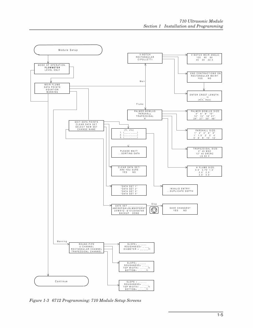
Figure 1-3 6712 Programming: 710 Module Setup Screens
M O D E O F O P E R A T I O N : F L O W M E T E R L E V E L O N L Y
V - N O T C H W E I R A N G L E :1 2 0 9 0 6 0
4 5 3 0 2 2 . 5
C L E A R D A T A S E T !A R E Y O U S U R E
Y E S N O
E D I T D A T A P O I N T SC L E A R D A T A S E TS E L E C T N E W S E T
C H A N G E N A M E
D A T A S E T _ _ _ _ _ _ _ _ _ _A B C D E F G H I J K L M N O P Q R S T
U V W X Y Z - & " 0 1 2 3 4 5 6 7 8 9B A C K U P D O N E
" D A T A S E T 1 "" D A T A S E T 2 "" D A T A S E T 3 "" D A T A S E T 4 "
S A V E C H A N G E S ?Y E S N O
W E I R F L U M ED A T A P O I N T S
E Q U A T I O NM A N N I N G
V - N O T C HR E C T A N G U L A R
C I P O L L E T T I
E N T E R C R E S T L E N G T H :_ . _ _ f t
( m i n , m a x )
P A L M E R - B O W L U SP A R S H A L L
T R A P E Z O I D A LH
E N D C O N T R A C T I O N S O NR E C T A N G U L A R W E I R ?
Y E S N O
P A L M E R - B O W L U S S I Z E :4 " 6 " 8 " 1 0 "
1 2 " 1 5 " 1 8 " 2 1 "2 4 " 2 7 " 3 0 " 4 8 "
P A R S H A L L S I Z E :1 " 2 " 3 " 6 " 9 "
1 ' 1 . 5 ' 2 ' 3 ' 4 '5 ' 6 ' 8 ' 1 0 ' 1 2 '
T R A P E Z O I D A L S I Z E :2 " 4 5 W S C
1 2 " 4 5 S R C R CL G 6 0 V
H F L U M E S I Z E :0 . 5 ' 0 . 7 5 ' 1 . 0 '
2 . 0 ' 2 . 5 '3 . 0 ' 4 . 5 '
( f t , c f s )1 . ( _ _ _ _ . _ _ _ _ )2 . ( _ _ _ _ , _ _ _ _ )3 . ( _ _ _ _ , _ _ _ _ )
P L E A S E W A I T !. . . S O R T I N G D A T A
I N V A L I D E N T R Y !. . . D U P L I C A T E D E P T H
S L O P E = _ . _ _ _ _R O U G H N E S S = _ . _ _ _
T O P W I D T H = _ _ . _ _ _ f tB O T T O M = _ _ . _ _ _ f t
S L O P E = _ . _ _ _ _R O U G H N E S S = _ . _ _ _
T O P W I D T H = _ _ . _ _ _ f tB O T T O M = _ _ . _ _ _ f t
R O U N D P I P EU - C H A N N E L
R E C T A N G U L A R C H A N N E LT R A P E Z O I D A L C H A N N E L
S L O P E = _ . _ _ _ _R O U G H N E S S = _ . _ _ _
D I A M E T E R = _ _ . _ _ _ f t
S t o p
W e i r
F l u m e
C o n t i n u e
M o d u l e S e t u p
M a n n i n g
710 Ultrasonic ModuleSection 1 Installation and Programming
1-6
Figure 1-4 6712 Programming: 710 Quick View Screens
S I T E D E S C R I P T I O N :" F A C T O R Y "
M O D U L E I N S E R T E D - -D O W N L O A D D A T A N O W
O R L O S E A L L D A T A !D O N E
6 7 1 2 S A M P L E RE X T E N D E D P R O G R A M M I N G
F O R H E L P A T A N YS C R E E N P R E S S ? K E Y
R U NP R O G R A M
V I E W R E P O R TO T H E R F U N C T I O N S
S E L E C T U N I T S F O RF L O W R A T E :
c f s g p s g p m M g dl p s m 3 s m 3 h m 3 d
S E L E C T E D U N I T S F O RL E N G T H :
f t m
U N I T S S E L E C T E D :L E N G T H : f t
U N I T S S E L E C T E D :F L O W R A T E : c f s
F L O W V O L U M E : M g a lS E L E C T U N I T S F O R
F L O W V O L U M E :c f g a l M g a l
m 3 l i t
P R O G R A M N A M E :" E X T E N D E D 1 "
S I T E D E S C R I P T I O N" F A C T O R Y
6 7 1 2 S A M P L E RS T A N D A R D P R O G R A M M I N G
F O R H E L P A T A N Y S C R E E N P R E S S ? K E Y
R U N " E X T E N D E D 1 "P R O G R A M
V I E W R E P O R TO T H E R F U N C T I O N S
S e es a m p l e rm a n u a l .
S e es a m p l e rm a n u a l .
S t a n d a r d E x t e n d e d
U L T R A S O N I C M O D U L EW E I R
9 0V - N O T C H
C U R R E N T L E V E L I S_ _ . _ _ f t
A D J U S T L E V E L T O_ _ . _ _ f t
C U R R E N T L E V E L I S_ _ . _ _ f t
_ _ M I N U T ED A T A I N T E R V A L
_ _ . _ _ f tA R E Y O U S U R E ?
Y E S N O
D A T A S T O R A G EI N T E R V A L I N M I N U T E S :
1 2 51 0 1 5 3 0
C o n t i n u e w i t h t h e s a m p l e r p r o g r a m m i n gs e q u e n c e ( s e e s a m p l e r m a n u a l ) .
Note:To program the module orrun a program that requiresa module, you must plug inthe module before turningon the 6712 controller.
T h i s s c r e e n a p p e a r s o n l y w h e n a m o d u l e h a s b e e n c h a n g e d o r i f t h e m o d u l e w a s u n p l u g g e d w h i l e t h e s a m p l e r w a s p o w e r e d .
See Figure 1-3, Module Setup.
710 Ultrasonic ModuleSection 1 Installation and Programming
1-7
1.3 Mounting theUltrasonic LevelSensor
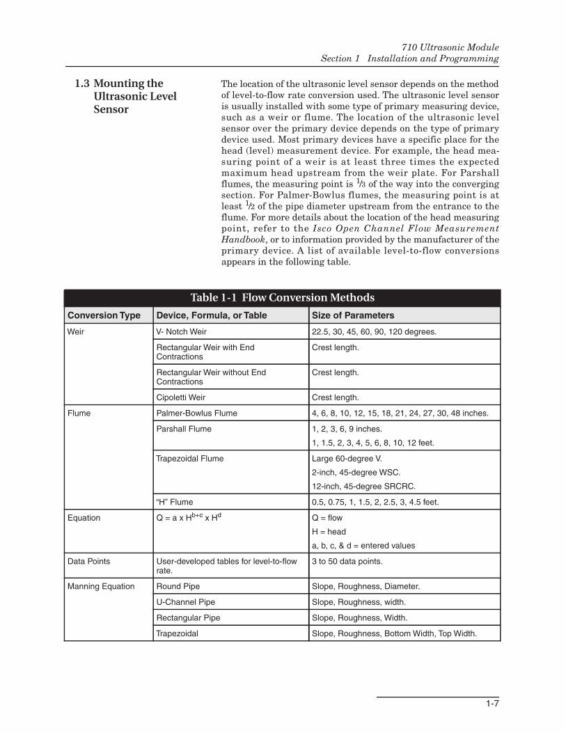
The location of the ultrasonic level sensor depends on the methodof level-to-flow rate conversion used. The ultrasonic level sensoris usually installed with some type of primary measuring device,such as a weir or flume. The location of the ultrasonic levelsensor over the primary device depends on the type of primarydevice used. Most primary devices have a specific place for thehead (level) measurement device. For example, the head mea-suring point of a weir is at least three times the expectedmaximum head upstream from the weir plate. For Parshallflumes, the measuring point is 1/3 of the way into the convergingsection. For Palmer-Bowlus flumes, the measuring point is atleast 1/2 of the pipe diameter upstream from the entrance to theflume. For more details about the location of the head measuringpoint, refer to the Isco Open Channel Flow MeasurementHandbook, or to information provided by the manufacturer of theprimary device. A list of available level-to-flow conversionsappears in the following table.
Table 1-1 Flow Conversion Methods
Conversion Type Device, Formula, or Table Size of Parameters
Weir V- Notch Weir 22.5, 30, 45, 60, 90, 120 degrees.
Rectangular Weir with EndContractions
Crest length.
Rectangular Weir without EndContractions
Crest length.
Cipoletti Weir Crest length.
Flume Palmer-Bowlus Flume 4, 6, 8, 10, 12, 15, 18, 21, 24, 27, 30, 48 inches.
Parshall Flume 1, 2, 3, 6, 9 inches.
1, 1.5, 2, 3, 4, 5, 6, 8, 10, 12 feet.
Trapezoidal Flume Large 60-degree V.
2-inch, 45-degree WSC.
12-inch, 45-degree SRCRC.
“H” Flume 0.5, 0.75, 1, 1.5, 2, 2.5, 3, 4.5 feet.
Equation Q = a x Hb+c x Hd Q = flow
H = head
a, b, c, & d = entered values
Data Points User-developed tables for level-to-flowrate.
3 to 50 data points.
Manning Equation Round Pipe Slope, Roughness, Diameter.
U-Channel Pipe Slope, Roughness, width.
Rectangular Pipe Slope, Roughness, Width.
Trapezoidal Slope, Roughness, Bottom Width, Top Width.
710 Ultrasonic ModuleSection 1 Installation and Programming
1-8
1.3.1 User-DeterminedMounting Location
If you intend to measure flow by some other means, such as agravity flow equation (Manning) or by calibrating a section of theflow channel, you will have to determine the location for theultrasonic level sensor. You should base this location on thehydraulic characteristics of the site and the method oflevel-to-flow rate conversion used.
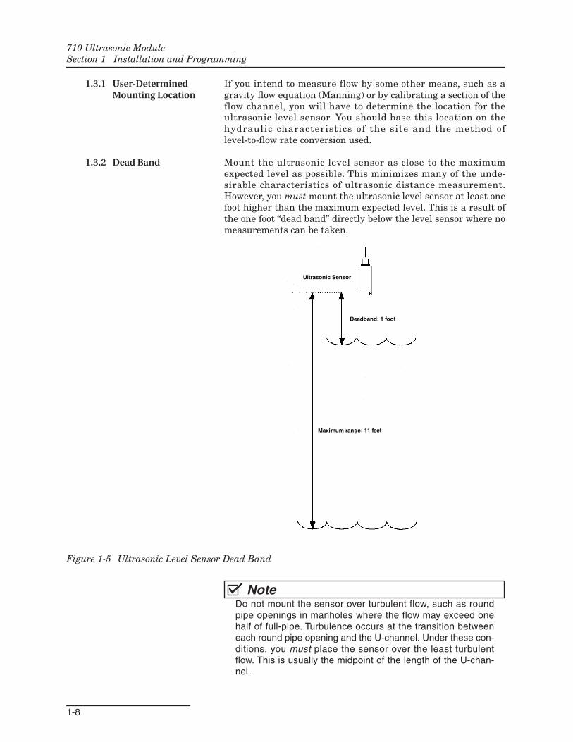
1.3.2 Dead Band Mount the ultrasonic level sensor as close to the maximumexpected level as possible. This minimizes many of the unde-sirable characteristics of ultrasonic distance measurement.However, you must mount the ultrasonic level sensor at least onefoot higher than the maximum expected level. This is a result ofthe one foot “dead band” directly below the level sensor where nomeasurements can be taken.
Figure 1-5 Ultrasonic Level Sensor Dead Band
NoteDo not mount the sensor over turbulent flow, such as roundpipe openings in manholes where the flow may exceed onehalf of full-pipe. Turbulence occurs at the transition betweeneach round pipe opening and the U-channel. Under these con-ditions, you must place the sensor over the least turbulentflow. This is usually the midpoint of the length of the U-chan-nel.
Ultrasonic Sensor
Deadband: 1 foot
Maximum range: 11 feet
710 Ultrasonic ModuleSection 1 Installation and Programming
1-9
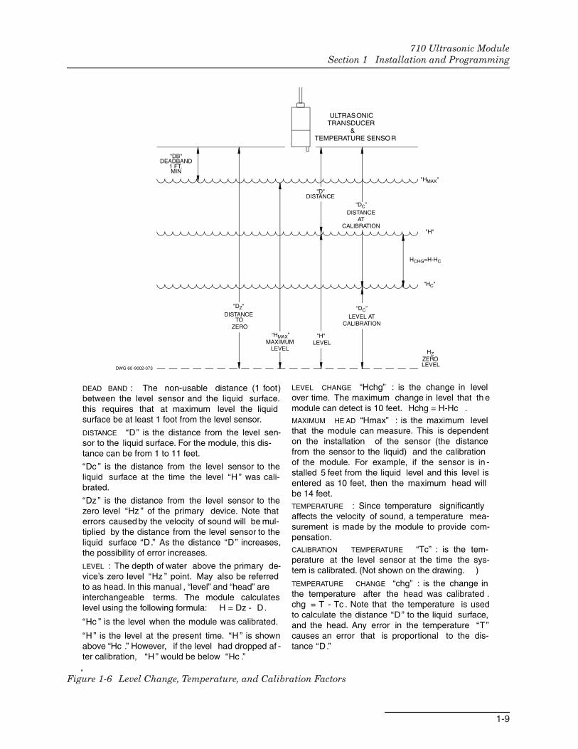
Figure 1-6 Level Change, Temperature, and Calibration Factors
“DC”
HCHG=H-HC
"HC"
"H"
"HMAX"
"D"DISTANCE
"DZ"
DISTANCETO
ZERO
"DB"DEADBAND
1 FT.MIN
HZZEROLEVEL
"H"LEVELMAXIMUM
LEVEL
DWG 60-9002-073
“HMAX”
“DC”
ULTRASONIC TRANSDUCER &TEMPERATURE SENSO R
DISTANCEAT
CALIBRATION
LEVEL ATCALIBRATION
LEVEL CHANGE “Hchg” : is the change in levelover time. The maximum change in level that th emodule can detect is 10 feet. Hchg = H-Hc .MAXIMUM HE AD “Hmax” : is the maximum levelthat the module can measure. This is dependenton the installation of the sensor (the distancefrom the sensor to the liquid) and the calibrationof the module. For example, if the sensor is in -stalled 5 feet from the liquid level and this level isentered as 10 feet, then the maximum head willbe 14 feet.TEMPERATURE : Since temperature significantlyaffects the velocity of sound, a temperature mea-surement is made by the module to provide com-pensation.CALIBRATION TEMPERATURE “Tc” : is the tem-perature at the level sensor at the time the sys-tem is calibrated. (Not shown on the drawing. )
TEMPERATURE CHANGE “chg” : is the change inthe temperature after the head was calibrated .chg = T - Tc . Note that the temperature is usedto calculate the distance “D” to the liquid surface,and the head. Any error in the temperature “T”causes an error that is proportional to the dis-tance “D.”
DEAD BAND : The non-usable distance (1 foot)between the level sensor and the liquid surface.this requires that at maximum level the liquidsurface be at least 1 foot from the level sensor.
DISTANCE “D” is the distance from the level sen-sor to the liquid surface. For the module, this dis-tance can be from 1 to 11 feet.
“Dc ” is the distance from the level sensor to theliquid surface at the time the level “H ” was cali-brated.
“Dz ” is the distance from the level sensor to thezero level “Hz ” of the primary device. Note thaterrors caused by the velocity of sound will be mul-tiplied by the distance from the level sensor to theliquid surface “D.” As the distance “D” increases,the possibility of error increases.
LEVEL : The depth of water above the primary de-vice’s zero level “Hz ” point. May also be referredto as head. In this manual , “level” and “head” areinterchangeable terms. The module calculateslevel using the following formula: H = Dz - D.
“Hc ” is the level when the module was calibrated.
“H ” is the level at the present time. “H ” is shownabove “Hc .” However, if the level had dropped af -ter calibration, “H ” would be below “Hc .”
710 Ultrasonic ModuleSection 1 Installation and Programming
1-10
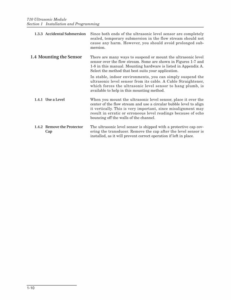
1.3.3 Accidental Submersion Since both ends of the ultrasonic level sensor are completelysealed, temporary submersion in the flow stream should notcause any harm. However, you should avoid prolonged sub-mersion.
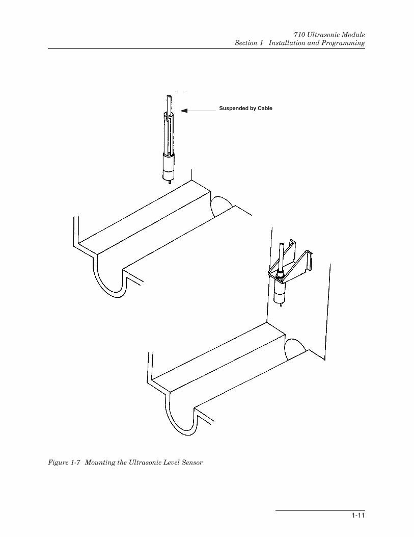
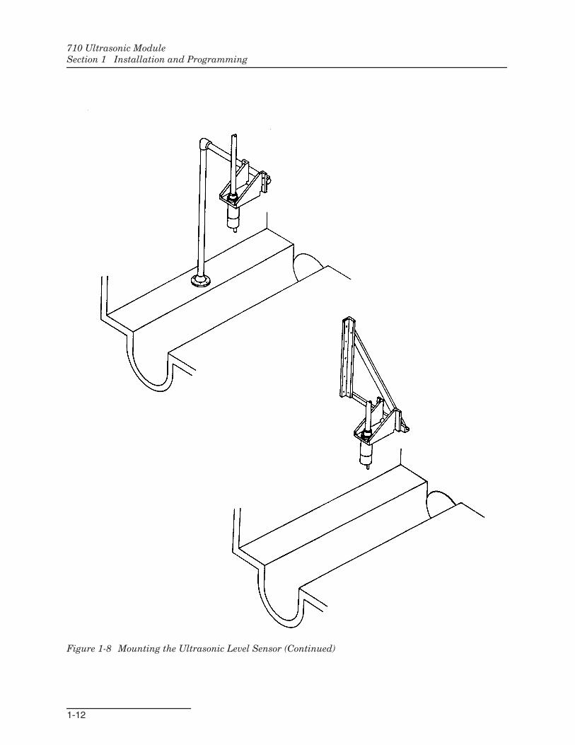
1.4 Mounting the Sensor There are many ways to suspend or mount the ultrasonic levelsensor over the flow stream. Some are shown in Figures 1-7 and1-8 in this manual. Mounting hardware is listed in Appendix A.Select the method that best suits your application.
In stable, indoor environments, you can simply suspend theultrasonic level sensor from its cable. A Cable Straightener,which forces the ultrasonic level sensor to hang plumb, isavailable to help in this mounting method.
1.4.1 Use a Level When you mount the ultrasonic level sensor, place it over thecenter of the flow stream and use a circular bubble level to alignit vertically. This is very important, since misalignment mayresult in erratic or erroneous level readings because of echobouncing off the walls of the channel.
1.4.2 Remove the ProtectorCap
The ultrasonic level sensor is shipped with a protective cap cov-ering the transducer. Remove the cap after the level sensor isinstalled, as it will prevent correct operation if left in place.
710 Ultrasonic ModuleSection 1 Installation and Programming
1-11
Figure 1-7 Mounting the Ultrasonic Level Sensor
Suspended by Cable
710 Ultrasonic ModuleSection 1 Installation and Programming
1-12
Figure 1-8 Mounting the Ultrasonic Level Sensor (Continued)
710 Ultrasonic ModuleSection 1 Installation and Programming
1-13
1.5 Maintenance The ultrasonic level sensor requires little maintenance. It isencapsulated for protection from the environment. The levelsensor’s transducer surface is aluminum, coated with a Teflon®
film. Do not scratch or score the surface; the transducer may bedamaged.
If the transducer’s surface becomes contaminated due to longterm use or accidental submersion, operation of the unit may beimpaired. If this happens, clean the case with a brush, but do notbrush the transducer’s surface or it may be damaged. Clean thesurface of the transducer with gently flowing water.
Do not drop the assembly, nor attempt to take it apart. The ultra-sonic level sensor contains no user-serviceable parts. Its case iscompletely sealed to protect the internal components. Repair ofthe unit must be done at the factory. If you think your modulerequires repair, contact Isco’s Technical Service Department.
1.6 How to Get Help If you need help or have repair questions, contact Isco’s Tech-nical Service Department.
Isco Technical Service DepartmentP.O. Box 82531Lincoln, Nebraska, 68501 (USA)
Telephone: (866) 298-6174FAX: (402) 465-3022
Email: [email protected]
1.7 Flash Memory andSoftware Upgrades
The module has Flash memory to store its software. With Flashtechnology, you can upgrade your module’s software withoutsending it back to the factory or replacing a chip. To update themodule software, install the module in an Avalanche or 6712Sampler. Then connect the sampler power source and turn thesampler on. Connect the sampler to a computer and follow theinstructions received with your Flash Update program.
710 Ultrasonic ModuleSection 1 Installation and Programming
1-14
1.8 TechnicalSpecifications
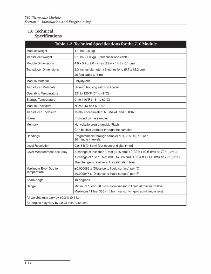
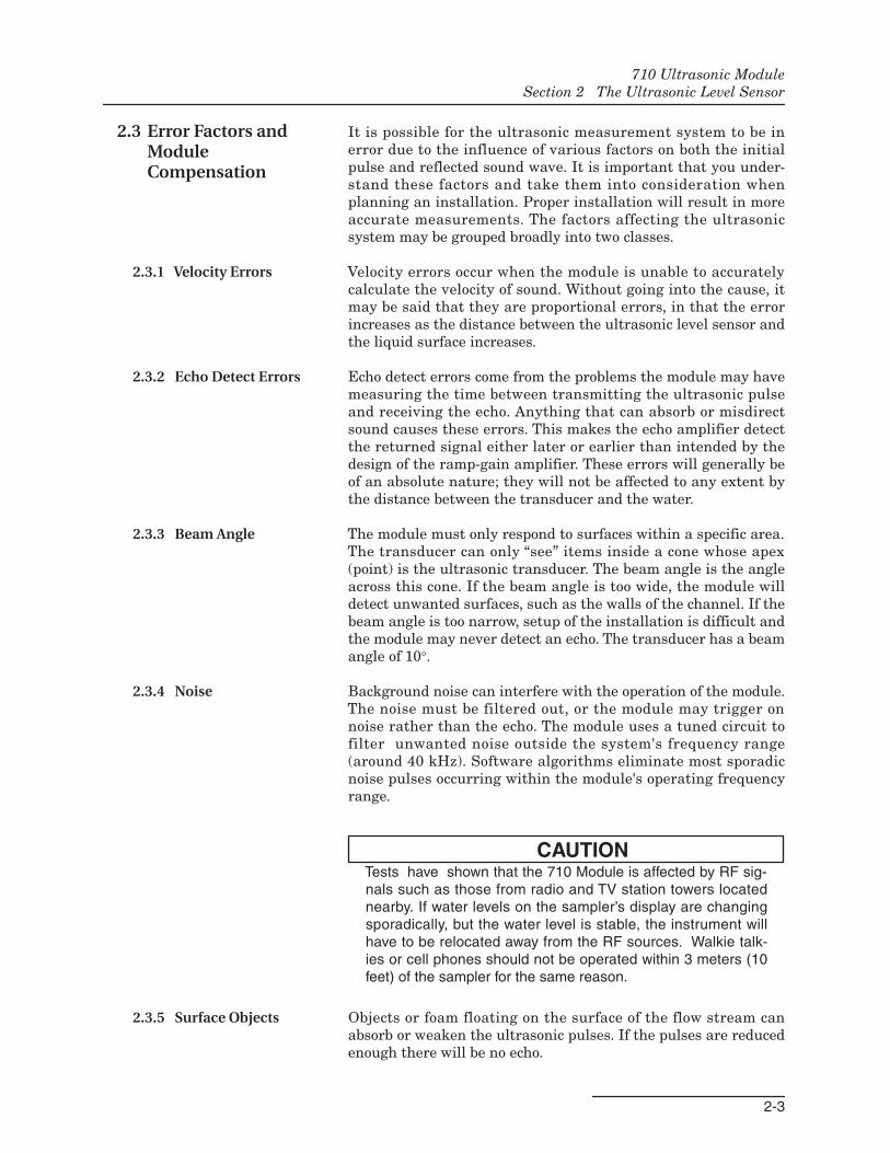
Table 1-2 Technical Specifications for the 710 Module
Module Weight 1.1 lbs (0.5 kg)
Transducer Weight 2.1 lbs. (1.0 kg) (transducer and cable)
Module Dimensions 4.9 x 5.7 x 2.0 inches (12.4 x 14.5 x 5.1 cm)
Transducer Dimensions 2.3 inches diameter x 6 inches long (5.7 x 15.2 cm)
25 foot cable (7.6 m)
Module Material Polystyrene
Transducer Materials Delrin ® housing with PVC cable
Operating Temperature 32° to 120°F (0° to 49°C)
Storage Temperature 0° to 140°F (-18° to 60°C)
Module Enclosure NEMA 4X and 6, IP67
Transducer Enclosure Totally encapsulated: NEMA 4X and 6, IP67
Power Provided by the sampler
Memory Nonvolatile programmable Flash
Can be field updated through the sampler
Readings Programmable through sampler at 1, 2, 5, 10, 15, and30 minute intervals
Level Resolution 0.013 ft (0.4 cm) [per count of digital timer]
Level Measurement Accuracy A change of less than 1 foot (30.5 cm): ±0.02 ft (±0.6 cm) at 72°F(22°C)
A change of 1 to 10 feet (30.5 to 305 cm): ±0.04 ft (±1.2 cm) at 72°F(22°C)
The change is relative to the calibration level.
Maximum Error Due toTemperature
±0.000085 x (Distance to liquid surface) per °C
±0.000047 x (Distance to liquid surface) per °F
Beam Angle 10 degrees
Range Minimum 1 foot (30.5 cm) from sensor to liquid at maximum level.
Maximum 11 feet 335 cm) from sensor to liquid at minimum level.
All weights may vary by ±0.2 lb (0.1 kg)
All lengths may vary by ±0.25 inch (0.64 cm)
2-1
710 Ultrasonic Module
Section 2 The Ultrasonic Level Sensor
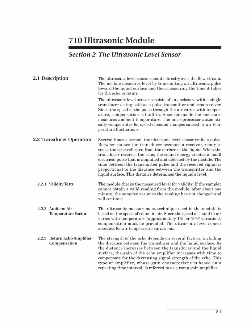
2.1 Description The ultrasonic level sensor mounts directly over the flow stream.The module measures level by transmitting an ultrasonic pulsetoward the liquid surface and then measuring the time it takesfor the echo to return.
The ultrasonic level sensor consists of an enclosure with a singletransducer acting both as a pulse transmitter and echo receiver.Since the speed of the pulse through the air varies with temper-ature, compensation is built in. A sensor inside the enclosuremeasures ambient temperature. The microprocessor automati-cally compensates for speed-of-sound changes caused by air tem-perature fluctuations.
2.2 Transducer Operation Several times a second, the ultrasonic level sensor emits a pulse.Between pulses the transducer becomes a receiver, ready tosense the echo reflected from the surface of the liquid. When thetransducer receives the echo, the sound energy creates a smallelectrical pulse that is amplified and detected by the module. Thetime between the transmitted pulse and the received signal isproportional to the distance between the transmitter and theliquid surface. This distance determines the liquid’s level.
2.2.1 Validity Tests The module checks the measured level for validity. If the samplercannot obtain a valid reading from the module, after about oneminute, the sampler assumes the reading has not changed andwill continue.
2.2.2 Ambient AirTemperature Factor
The ultrasonic measurement technique used in the module isbased on the speed of sound in air. Since the speed of sound in airvaries with temperature (approximately 1% for 10°F variation),compensation must be provided. The ultrasonic level sensoraccounts for air temperature variations.
2.2.3 Return Echo AmplifierCompensation
The strength of the echo depends on several factors, includingthe distance between the transducer and the liquid surface. Asthe distance increases between the transducer and the liquidsurface, the gain of the echo amplifier increases with time tocompensate for the decreasing signal strength of the echo. Thistype of amplifier, whose gain characteristic is based on arepeating time interval, is referred to as a ramp-gain amplifier.
710 Ultrasonic ModuleSection 2 The Ultrasonic Level Sensor
2-2
Figure 2-1 Ultrasonic Level Sensor Operation
710 Ultrasonic ModuleSection 2 The Ultrasonic Level Sensor
2-3
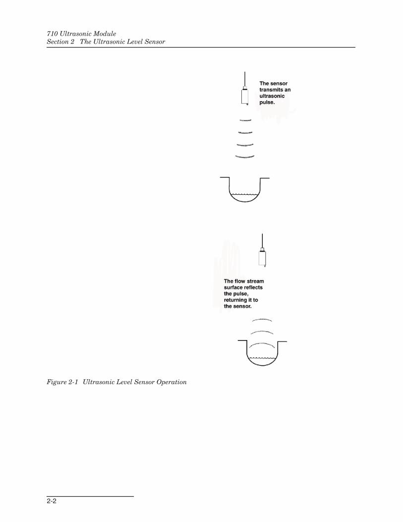
2.3 Error Factors andModuleCompensation
It is possible for the ultrasonic measurement system to be inerror due to the influence of various factors on both the initialpulse and reflected sound wave. It is important that you under-stand these factors and take them into consideration whenplanning an installation. Proper installation will result in moreaccurate measurements. The factors affecting the ultrasonicsystem may be grouped broadly into two classes.
2.3.1 Velocity Errors Velocity errors occur when the module is unable to accuratelycalculate the velocity of sound. Without going into the cause, itmay be said that they are proportional errors, in that the errorincreases as the distance between the ultrasonic level sensor andthe liquid surface increases.
2.3.2 Echo Detect Errors Echo detect errors come from the problems the module may havemeasuring the time between transmitting the ultrasonic pulseand receiving the echo. Anything that can absorb or misdirectsound causes these errors. This makes the echo amplifier detectthe returned signal either later or earlier than intended by thedesign of the ramp-gain amplifier. These errors will generally beof an absolute nature; they will not be affected to any extent bythe distance between the transducer and the water.
2.3.3 Beam Angle The module must only respond to surfaces within a specific area.The transducer can only “see” items inside a cone whose apex(point) is the ultrasonic transducer. The beam angle is the angleacross this cone. If the beam angle is too wide, the module willdetect unwanted surfaces, such as the walls of the channel. If thebeam angle is too narrow, setup of the installation is difficult andthe module may never detect an echo. The transducer has a beamangle of 10°.
2.3.4 Noise Background noise can interfere with the operation of the module.The noise must be filtered out, or the module may trigger onnoise rather than the echo. The module uses a tuned circuit tofilter unwanted noise outside the system's frequency range(around 40 kHz). Software algorithms eliminate most sporadicnoise pulses occurring within the module's operating frequencyrange.
CAUTIONTests have shown that the 710 Module is affected by RF sig-nals such as those from radio and TV station towers locatednearby. If water levels on the sampler’s display are changingsporadically, but the water level is stable, the instrument willhave to be relocated away from the RF sources. Walkie talk-ies or cell phones should not be operated within 3 meters (10feet) of the sampler for the same reason.
2.3.5 Surface Objects Objects or foam floating on the surface of the flow stream canabsorb or weaken the ultrasonic pulses. If the pulses are reducedenough there will be no echo.
710 Ultrasonic ModuleSection 2 The Ultrasonic Level Sensor
2-4
2.3.6 Temperature Temperature changes have a significant effect on the velocity ofsound (approximately 7% between 32° and 104°F). Consequently,the module provides temperature compensation. There is a tem-perature sensor embedded in the housing of the ultrasonic levelsensor.
2.3.7 Waves Waves on the surface of the flow stream can deflect the soundenergy so it does not return to the transducer. Waves can alsocause the sound to return to the transducer by an indirect path.In the first case, the module will not receive an echo; in thesecond case, the additional time lapse will cause an echo error,indicated by an incorrect level reading. The module employs asoftware algorithm to reject occasional readings that deviate sub-stantially from normal. However, if the waves are severe, themodule will not function and will indicate a “no echo” condition.
2.3.8 Wavelength You can determine the wavelength of sound by dividing thevelocity of the sound by the frequency. The frequency of themodule is about 40 kHz. The length of a 40 kHz sound wave isfound by dividing 1,125 by 40,000 which is 0.02813 feet or 0.3375inches.
Under ideal conditions it is possible to detect the same wavefront of the returning echo. However, any noise or abnormalattenuation (excessive decrease) may cause the module to detectan earlier or a later wave. When the attenuation of the returnedecho does not match the gain slope of the amplifier, the circuitwill eventually detect a different cycle of the returned echo as thedistance changes. The impact of this wave-detect error is deter-mined by the wavelength. Higher frequencies (shorter wave-lengths) produce smaller echo-detect errors. However, higherfrequencies are absorbed more rapidly, decreasing the maximumdistance that you can measure with the same amount of power.The frequency of 40 kHz was selected for the module as asuitable compromise.
Since the sound travels the distance twice (going and coming),the observed error is one-half of the wavelength or 0.014 foot.The module uses a rectified detect circuit that can detect eitherthe positive or negative peak. This allows the module to limit theerror of proper wave detection to increments of one-half wave-length. This error is 0.007 foot.
2.3.9 Wind Wind can blow the sound away or significantly reduce theintensity of the returned echo. Narrow beam angles, advanta-geous for measuring small flow streams, are a disadvantage inthis situation. Likewise, greater distances to the surface of theflow stream are more affected by wind.
2.3.10 Other Factors Changes in barometric pressure provide no significant cause oferror. Humidity causes only a slight variation to the velocity ofsound (maximum 0.35% at 68°F). The module does not provideany compensation for humidity.
710 Ultrasonic ModuleSection 2 The Ultrasonic Level Sensor
2-5
2.4 Minimizing LevelMeasurement Errors
In order to minimize measurement errors with the ultrasoniclevel sensor, the following precautions should be observed wheninstalling the ultrasonic level sensor. These are listed in theapproximate order of their significance.
2.4.1 TemperatureDifferences
Isco recommends that you install the ultrasonic level sensorwhere the temperature of the sensor housing can represent theair temperature throughout the distance measured. Avoid loca-tions where the sensor will operate at a different temperaturethan the air between the level sensor and the flow stream.
Air temperature affects the speed of the transmitted pulse. Theultrasonic level sensor housing includes a sensor which providestemperature readings for the module. The module applies thesereadings to the level measurement calculation. If the temper-ature sensor does not provide an accurate reading, not only is theusefulness of temperature compensation defeated, but also ameasurement error will be multiplied by the distance the pulsemust travel.
When the module receives inaccurate temperature readings,level errors can be as great as 0.001 per foot for each degree oftemperature difference. For example, with a distance of only twofeet and a temperature difference of 35°F, the level error is:
Level Error = 0.001 x 35 x 2 = 0.070 foot
(about 1 inch)
Sunlight is a common factor that may cause the sensor to misrep-resent the ambient air temperature. Direct sunlight will warmthe sensor housing to a temperature greater than the sur-rounding air. Other factors include temperature inversions andlayers of air at different temperatures throughout the distancethe pulse must travel. Inversions or layers can also cause anabnormal reduction in the strength of the ultrasonic pulse.
If the ultrasonic level sensor is installed outside and directlyexposed to the sun, a sunshade should be installed. See theAccessories section in this manual for ordering information.
2.4.2 Avoid Wind The ultrasonic level sensor should be installed in a location pro-tected from air currents. Wind reduces the strength of the ultra-sonic pulse and echo. This causes the module to have difficultydetecting the proper wave in the echo. In severe cases, it is pos-sible for the module to lose the echo completely.
2.4.3 Excessive Distance Although the ultrasonic level sensor cannot be mounted closerthan twelve inches from the maximum level of the flow stream, itis recommended that the mounting be kept as close to the twelveinch limit as possible. The reason is that any error made by themodule in calculating the velocity of sound in the air is multi-plied by the distance from the level sensor to the surface of theflow stream. Minimizing the distance will minimize the error.
710 Ultrasonic ModuleSection 2 The Ultrasonic Level Sensor
2-6
2.4.4 CalibrationTemperature
Calibrate the level reading under temperature conditions as nearas possible to those expected during operation. If the sensor hasbeen moved through various temperatures before installation,you should allow it to stabilize before calibration.
For small changes of level, the error due to temperature is deter-mined by the product of distance and temperature change. Cali-brating at the same temperature as the operating temperaturewill minimize this error.
2.4.5 Water Condensation The ultrasonic level sensor will not operate properly if water con-denses on the transducer surface as a result of high ambienthumidity. Some users have found that mounting the transducerhorizontally and aiming it at a 45° angle reflector will keep waterfrom collecting on the transducer's radiating surface.
2.4.6 Foam, Oil, andTurbulence
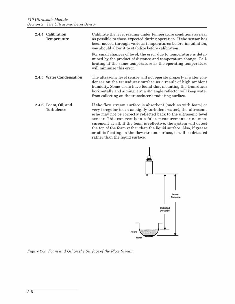
If the flow stream surface is absorbent (such as with foam) orvery irregular (such as highly turbulent water), the ultrasonicecho may not be correctly reflected back to the ultrasonic levelsensor. This can result in a false measurement or no mea-surement at all. If the foam is reflective, the system will detectthe top of the foam rather than the liquid surface. Also, if greaseor oil is floating on the flow stream surface, it will be detectedrather than the liquid surface.
Figure 2-2 Foam and Oil on the Surface of the Flow Stream
710 Ultrasonic ModuleSection 2 The Ultrasonic Level Sensor
2-7
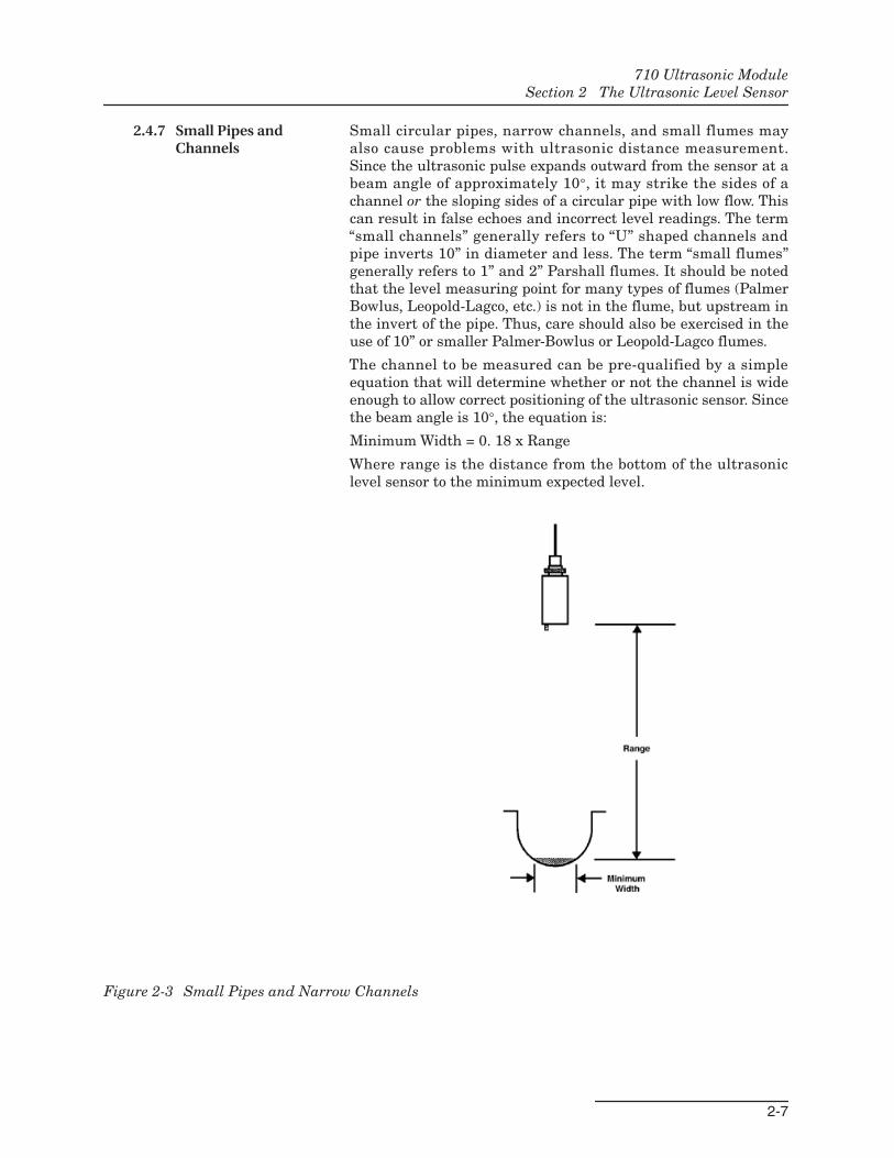
2.4.7 Small Pipes andChannels
Small circular pipes, narrow channels, and small flumes mayalso cause problems with ultrasonic distance measurement.Since the ultrasonic pulse expands outward from the sensor at abeam angle of approximately 10°, it may strike the sides of achannel or the sloping sides of a circular pipe with low flow. Thiscan result in false echoes and incorrect level readings. The term“small channels” generally refers to “U” shaped channels andpipe inverts 10” in diameter and less. The term “small flumes”generally refers to 1” and 2” Parshall flumes. It should be notedthat the level measuring point for many types of flumes (PalmerBowlus, Leopold-Lagco, etc.) is not in the flume, but upstream inthe invert of the pipe. Thus, care should also be exercised in theuse of 10” or smaller Palmer-Bowlus or Leopold-Lagco flumes.
The channel to be measured can be pre-qualified by a simpleequation that will determine whether or not the channel is wideenough to allow correct positioning of the ultrasonic sensor. Sincethe beam angle is 10°, the equation is:
Minimum Width = 0. 18 x Range
Where range is the distance from the bottom of the ultrasoniclevel sensor to the minimum expected level.
Figure 2-3 Small Pipes and Narrow Channels
710 Ultrasonic ModuleSection 2 The Ultrasonic Level Sensor
2-8
2.4.8 Alternative FlowMeasurement Systems
Because of the characteristics of ultrasonic flow measurement,there may be some installations where the ultrasonic method iseither unreliable or inaccurate. In these instances, it is worth-while to consider using an alternate method of flow mea-surement.
In addition to the 710 Module, Isco offers three other types ofplug-and-play flow modules in the 700 Series: the 730 BubblerModule, the 720 Submerged Probe Module, and the 750Area-Velocity Module.
Information about these flow modules is available from thefactory. Call for more information or visit our Web site atwww.isco.com.
A-1
710 Ultrasonic Module
Appendix A Accessories
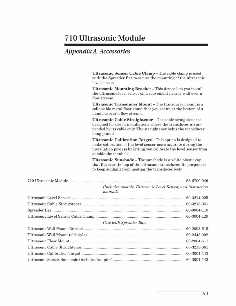
Ultrasonic Sensor Cable Clamp – The cable clamp is usedwith the Spreader Bar to secure the mounting of the ultrasoniclevel sensor.
Ultrasonic Mounting Bracket – This device lets you installthe ultrasonic level sensor on a convenient nearby wall over aflow stream.
Ultrasonic Transducer Mount – The transducer mount is acollapsible metal floor stand that you set up at the bottom of amanhole over a flow stream.
Ultrasonic Cable Straightener – The cable straightener isdesigned for use in installations where the transducer is sus-pended by its cable only. The straightener helps the transducerhang plumb.
Ultrasonic Calibration Target – This option is designed tomake calibration of the level sensor more accurate during theinstallation process by letting you calibrate the level sensor fromoutside the manhole.
Ultrasonic Sunshade – The sunshade is a white plastic capthat fits over the top of the ultrasonic transducer. Its purpose isto keep sunlight from heating the transducer body.
710 Ultrasonic Module ............................................................................................................ 68-6700-049
(Includes module, Ultrasonic Level Sensor, and instructionmanual)
Ultrasonic Level Sensor ........................................................................................................... 60-3214-025
Ultrasonic Cable Straightener................................................................................................. 60-3213-061
Spreader Bar............................................................................................................................. 60-3004-110
Ultrasonic Level Sensor Cable Clamp..................................................................................... 60-3004-129
(Use with Spreader Bar)
Ultrasonic Wall Mount Bracket ............................................................................................... 60-2003-615
Ultrasonic Wall Mount (old style)............................................................................................ 60-2443-092
Ultrasonic Floor Mount............................................................................................................ 60-2004-611
Ultrasonic Cable Straightener................................................................................................. 60-3213-061
Ultrasonic Calibration Target.................................................................................................. 60-3004-143
Ultrasonic Sensor Sunshade (Includes Adaptor) .................................................................... 60-3004-142
710 Ultrasonic ModuleAppendix A Accessories
A-2
Warranty
Before returning any instrument for repair, please call, fax, or e-mail the Teledyne Isco ServiceDepartment for instructions. Many problems can often be diagnosed and corrected over thephone, or by e-mail, without returning the instrument to the factory.Instruments needing factory repair should be packed carefully, and shipped to the attention ofthe service department. Small, non-fragile items can be sent by insured parcel post. PLEASEBE SURE TO ENCLOSE A NOTE EXPLAINING THE PROBLEM.
Shipping Address: Teledyne Isco - Attention Repair Service4700 Superior StreetLincoln, NE 68504 USA
Mailing Address: Teledyne IscoPO Box 82531Lincoln, NE 68501 USA
Phone: Repair service: (800) 775-2965 (lab instruments)(866) 298-6174 (samplers & flow meters)
Sales & General Information: (800) 228-4373 (USA & Canada)Fax: (402) 465-3001Email: [email protected]
October 11, 2013 P/N 60-1002-040 Rev H
Teledyne Isco One Year Limited Factory Service Warranty*This warranty exclusively covers Teledyne Isco
instruments, providing a one-year limited warranty
covering parts and labor.
Any instrument that fails during the warranty period due to
faulty parts or workmanship will be repaired at the factory
at no charge to the customer. Teledyne Isco�s exclusive
liability is limited to repair or replacement of defective
instruments. Teledyne Isco is not liable for consequential
damages.
Teledyne Isco will pay surface transportation charges both
ways within the 48 contiguous United States if the
instrument proves to be defective within 30 days of
shipment. Throughout the remainder of the warranty period,
the customer will pay to return the instrument to Teledyne
Isco, and Teledyne Isco will pay surface transportation to
return the repaired instrument to the customer. Teledyne
Isco will not pay air freight or customer�s packing and
crating charges. This warranty does not cover loss, damage,
or defects resulting from transportation between the
customer�s facility and the repair facility.
The warranty for any instrument is the one in effect on date
of shipment. The warranty period begins on the shipping
date, unless Teledyne Isco agrees in writing to a different
date.
Excluded from this warranty are normal wear; expendable
items such as pH sensors, charts, ribbon, lamps, tubing, and
glassware; fittings and wetted parts of valves; and damage
due to corrosion, misuse, accident, or lack of proper
maintenance. This warranty does not cover products not
sold under the Teledyne Isco trademark or for which any
other warranty is specifically stated.
No item may be returned for warranty service without a
return authorization number issued by Teledyne Isco.
This warranty is expressly in lieu of all other warranties
and obligations and Teledyne Isco specifically disclaims
any warranty of merchantability or fitness for a
particular purpose.
The warrantor is Teledyne Isco, 4700 Superior, Lincoln, NE
68504, U.S.A.
* This warranty applies to the USA and countries where Teledyne Isco does not have an authorized dealer.
Customers in countries outside the USA, where Teledyne Isco has an authorized dealer, should contact
their Teledyne Isco dealer for warranty service.

Related Documents