7/1 2TLC172001C0202 | ABB Safety Handbook 7

Welcome message from author
This document is posted to help you gain knowledge. Please leave a comment to let me know what you think about it! Share it to your friends and learn new things together.
Transcript

7/1 2TLC172001C0202 | ABB Safety Handbook
7

ABB Safety Handbook | 2TLC172001C0202 7/2
7
Light curtains, Light grids and Light beams
Why use light grids and light curtains? 7/3
Reset - 3 alternatives 7/5
Muting and blanking 7/6
Light curtain for short safety distance 7/7
Cycle initiation with light curtain 7/8
Safety distance 7/9
Light curtains, Light grids
Focus II 7/11
Muting units - MF-T, MF-L 7/16
Muting sensors - Mute R 7/18
Muting accessories - FMC, FMI 7/20
Accessories - MFII mirrors 7/22
Light protection stand - Bjorn 7/23
Protection against water and dust - WET 7/25
Blanking program - BP-1 7/26
Connection examples Focus II 7/27
Safety Light Beam
Spot 7/34
Connection examples 7/37

7/3 2TLC172001C0202 | ABB Safety Handbook
7
Why use light grids and light curtains?
Light grids and light curtains are production friendly safety components that causes no physical obstruction for the machine operator. Light barrier protection is also a good safety component to use when goods are to be passed in and out of a hazardous area.
How does a light grid/light curtain work?Both light grids and light curtains utilise optical transmitter and receiver units. From the transmitters beams of infrared light are sent to the receiver. When a light beam is interrupted a dual stop signal is given to the dangerous machines inside the light grid/curtain protected area.
What is the difference between a light curtain and a light grid?A light curtain has several beams that are placed closely to-gether whereas a light grid consists of only one, two, three or four light beams. The beams are closest on a light curtain that is used for finger detection. Then the resolution is 14 mm. For light grids the beams are normally placed at a relative distance of 300 to 500 mm. The choice between light grid or light cur-tain is often a question of available safety distance, reach and price. Light curtains are often chosen for short safe/minimum distances. Light grids are chosen for longer safe/minimum distances, long range up to 40 m and for a low price.

ABB Safety Handbook | 2TLC172001C0202 7/4
7
What safety requirements are there for a light protection device? High safety demands are stated in the standard EN 61496-1 which deals with light protection. The main demands are on a safe stopping function and that light from light sources other than the transmitter or other disturbances do not affect the safety function.
Depending on how the safety function is built up there are safety components of type 2 and 4 to choose between. Type 2 and 4 relates in principle category 2/PL c and category 4/PL e according to EN ISO 13849-1.
Type 4 which has the highest safety level, states that a fault is not allowed to affect the safety function and that the fault shall be detected by the outputs falling immediately or that they do not re-connect after being disconnected. Maximum allowed scattering angle for the light is ±2.5°.
Light grids for long distances Light grids with monitored by-passing during material transport
Light curtain for short safe/minimum distances
Light curtain as area protection
Light curtain to protect during cycle initiation
Type 2 states that a simple but monitored safety function is required, which means that the safety function shall be moni-tored through periodic tests which break the output when a fault occurs. Between the testing times there can though be faults which result in the safety component malfunctioning. The test function can either be built into the safety device or an external unit (e.g. the machine´s control system) can initiate a test. Maximum allowed scattering angle for the light is ±5°.
Light grids and light curtains are included among the products in the machine directive´s appendix 4, which means that an external certifying procedure with an officially recognised institution is called for.
Light curtain for inner area limiting

7/5 2TLC172001C0202 | ABB Safety Handbook
7
12
A
ab
B
Button 1 is pressed and afterwards, within a chosen time e.g. 5 seconds, button 2 is pressed for resetting the light beam.
Reset button with light indication.
A light beam b indicates that the robot is situated in area A. In this position it is possible to walk in through the gate to area B without stopping the robot.
Reset – 3 alternatives
Supervised manual reset When a light curtain/grid is interrupted it will give a stop signal to dangerous machines within the hazardous area it protects and a reset-lamp can be lit. For a new start of the machine the light curtain/grid has to be reset. This is done with the reset button which is placed where the whole hazardous area can be supervised and can not be reached from within the area which it protects.. There are high requirements on the reset function - neither a short circuit nor a component fault shall give automatic reset. When the reset button has been set the outputs are activated and the reset-lamp is turned off.
Automatic reset Automatic reset is used when the light beam is used for area monitoring. When the light beam is actuated this indicates that e.g. a robot is in the area. The robot is stopped if a per-son enters the same area e.g. through a gate. When the light beam is free again the control unit will be reset automatically.
Supervised time-reset When supervised time-reset (pre-reset) is in use, its purpose is not to allow a reset from outside the protected area without first having confirmed that no-one is out of sight within the area. To reset the light beam (see figure) button 1 must first be pressed and afterwards button 2 within e.g. 5 seconds. This is especially important when one cannot see the entire area that is protected by the light beam.

ABB Safety Handbook | 2TLC172001C0202 7/6
7
Bypassing may be needed for different reasons. One of the most common reasons for bypassing is during in and out feeding of material on a conveyor, Automated guided vehicle (AGV), etc. Another common application is bypassing while passing with a three-position device to the hazardous area.
Important aspects for bypassing is that it shall be safe, not be activated by mistake and be difficult to defeat. In other words it shall give a reliable bypassing when a loading carrier enters but not allow a human to pass. To achieve the highest safety level a dual and supervised bypassing system is needed (usually with at least two independent signals). If this is done with sensors, it is recommended they be of different kinds, because of the probability of them both malfunctioning for the same reason e.g. common cause failure. An example of a solution is to use a mechanical limit switch and a photo-cell sensor.
To avoid deliberate defeating/manipulation of the bypassing sensors/signals a safety relay or a safety-PLC is connected thereby monitoring that the sensors are both activated and deactivated in every bypassing cycle.
The number of variations in bypassing systems are almost infinite. This depends on the specific requirements of each plant/machine. For Focus II there are a number of bypassing possibilities prepared.
Automatic bypassing of light grid when an Automated guided vehicle passes.
Muting (bypassing)
Blanking
Blanking means permanent switching off of a number of be-ams in the detection zone of a light curtain. This is a function that is permitted and used when an object that is larger than the resolution of the light curtain is permanently located in the detection zone, without deactivating the safety outputs (OSSD). If the object is removed from the detection zone, the safety outputs are deactivated.
Blanking function has different tolerance settings that allow movement or vibration of the objects that obscure the detec-tion zone.
One tolerance setting can be called ”Floating blanking”, that means that the part of the zone which is intentionally blocked can be moved around in the detection zone while the ma-chinery is operating. Other beams are active and providing normal protection, but often with reduced resolution.
When a “blanking” function is used, it is very important that the light curtain provides protection and can detect objects, as small as a finger or hand, depending on the resolution, anywhere outside the zone that is rendered inactive because the object is there. Blanking may require an additional fixed guard and may require additonal minimum distance to the dangerous movment.
It must not be possible to select the “blanking function” wit-hout using a key, tool or similar unlocking device.

7/7 2TLC172001C0202 | ABB Safety Handbook
7
A light curtain can be used in a machine or a production plant in the same way as a hatch. There is a great difference though when it comes to the risk situation. When one has a light curtain installed with a short minimum distance in front of a dangerous machine, there is a high risk for spontaneous engagement into the machine, often called after-grasp. If the dangerous machine movement does not stop during such an engagement, one has a small chance of avoiding injury. Therefore it is of great importance that the whole chain in the stopping circuit is dual and supervised. Even valves and contactors which ultimately control dangerous movements normally have to be doubled up and supervised. Regulations concerning safety distances are given in specific C-standards such as EN 692 for mechanical presses. If no specific C-standard is available, EN ISO 13855 is used.
Automatic machinesFor light curtains on automatic machines there shall be a reset function which is active when the machine is set for automatic production whether or not it is a passable protection. After affected a light curtain, one must first use a reset function then the restart of the cycle shall be made with a separate starting device. The same reset applies for machines with semi-automatic drive.
Operator protection during manually serviced machinesManually operated machines where one or more operators pick in and out parts between every cycle are the most risky light curtain applications. This because of the number of en-gagements into the machine´s hazardous area is often several times per minute.
Light curtains on pressesLight curtains have traditionally been a common protection method among press applications and there has since long existed detailed information on the usage of light curtains on presses. (see next spread for “Cycle initiation with light cur-tain“). Only light curtains of type 4 are accepted on presses.
ResetOn the servicing side i.e. the side or sides where there is an operator that picks in and out parts, there shall be a separate reset function for the light curtain, usually a button. If there are several light curtains e.g. on the front and back there shall be one for each. If the light curtain is actuated during a dange-rous movement the press shall not be able to restart without being reset. During engagement after the end of the cycle no reset is needed.
Hand resolution
Finger resolution
Light curtain for short safety distance
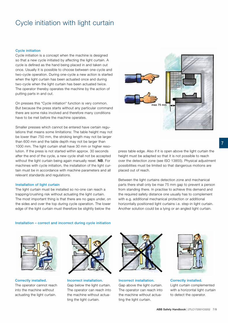
ABB Safety Handbook | 2TLC172001C0202 7/8
7
max 75 mm
Installation – correct and incorrect during cycle initiation
Cycle initiationCycle initiation is a concept when the machine is designed so that a new cycle initiated by affecting the light curtain. A cycle is defined as the hand being placed in and taken out once. Usually it is possible to choose between one-cycle and two-cycle operation. During one-cycle a new action is started when the light curtain has been actuated once and during two-cycle when the light curtain has been actuated twice. The operator thereby operates the machine by the action of putting parts in and out.
On presses this “Cycle initiation“ function is very common. But because the press starts without any particular command there are some risks involved and therefore many conditions have to be met before the machine operates.
Smaller presses which cannot be entered have certain regu-lations that means some limitations: The table height may not be lower than 750 mm, the stroking length may not be larger than 600 mm and the table depth may not be larger than 1000 mm. The light curtain shall have 30 mm or higher reso-lution. If the press is not started within approx. 30 seconds after the end of the cycle, a new cycle shall not be accepted without the light curtain being again manually reset. NB. For machines with cycle initiation, the installation of the light cur-tain must be in accordance with machine parameters and all relevant standards and regulations.
Correctly installed. The operator cannot reach into the machine without actuating the light curtain.
Incorrect installation. Gap below the light curtain. The operator can reach into the machine without actua-ting the light curtain.
Incorrect installation. Gap above the light curtain. The operator can reach into the machine without actua-ting the light curtain.
Cycle initiation with light curtain
Correctly installed. Light curtain complemented with a horizontal light curtain to detect the operator.
Installation of light curtain The light curtain must be installed so no-one can reach a trapping/crushing risk without actuating the light curtain. The most important thing is that there are no gaps under, on the sides and over the top during cycle operation. The lower edge of the light curtain must therefore be slightly below the
press table edge. Also if it is open above the light curtain the height must be adapted so that it is not possible to reach over the detection zone (see ISO 13855). Physical adjustment possibilities must be limited so that dangerous motions are placed out of reach. Between the light curtains detection zone and mechanical parts there shall only be max 75 mm gap to prevent a person from standing there. In practise to achieve this demand and the required safety distance one usually has to complement with e.g. additional mechanical protection or additional horizontally positioned light curtains i.e. step-in light curtain. Another solution could be a lying or an angled light curtain.

7/9 2TLC172001C0202 | ABB Safety Handbook
7
Minimum distance for light protection according to EN ISO 13855
The distance ’S’ is a minimum distance between a light curtain and a hazardous area. The distance shall prevent that a person is not able to reach a hazardous ma-chine part before the machine movement has stopped. This is calculated with the formula from EN ISO 13855 - Safety of machinery - Positioning of safeguards with respect to the approach speeds of parts of the human body.
S = (K x T) + C
Minimum distances for vertical and horizontal installed light curtains according to EN ISO 13855
S = minimum distance in mmH1 = the lower beam may not be situated higher than 300 mm above the groundH2 = the upper beam may not be situated lower than 900 mm above the ground
S = minimum distance in mmH = the light curtain detection zone must be positioned bet-ween 0 and 1000 mm above the floor
S = minimum distance in mmK = body/part of body (e.g. hand) speed in mm/sT = T1 + T2 where T1 = the safety device´s reaction time in secondsT2 = the machine´s reaction time in secondsC = additional distance in mm based upon the body´s intrusi-on towards the hazardous area before the safety device has been actuated.
For S ≤ 500 mm the minimum distance for vertical installation is calculated with the following formula:
S = (2000 x T) + 8 x (d-14)
where d is the light curtain´s resolution in mm.
K here is 2000 mm/s which represents the speed of the hand. The expression (8 x (d-14)) may never be less than 0. Mini-mum distance S is 100 mm.
If the minimum distance according to the formula above gets larger than 500 mm one can instead use:
S = (1600 x T) + 8 x (d-14)
K is1600 mm/s which represents the speed of the body. Mini-mum distance according to this formula is 500 mm.
The minimum distance for horizontal installation is calculated with the following formula:
S = (1600 x T) + (1200 - 0.4 x H)
where H is the height of the detection zone above the refe-rence plane, e.g. the ground
(1200 – 0,4 x H) may not be less than 850 mm. Depending on the resolution, d, that the light curtain has, there is a minimum height that the detection zone may be placed. This is calcula-ted with:H = 15 x (d – 50). H cannot be less than 0. With a resolution d =14 or 30 mm one can therefore install the light curtain from H = 0 and up. The higher it is situated, the shorter the minimum distance gets. The highest permissible height H of the detection zone is 1000 mm.
When you use a horizontal light curtain as entry protection, the depth of the light curtain shall be at least 750 mm to pre-vent people from inadvertently stepping over it. The estimated minimum distance is measured from the machine’s hazardous section to the outermost beam of the horizontal light curtain (seen from the machine).
Resolution for finger (≤14 mm) gives C = 0
NB If it is possible to reach the hazard zone by reaching over the light beam, an addition is made to the formula. In table 1 in EN ISO 13855 an alternative safety distance addition (Cro) is given to the formula S = (K x T) + C. The greatest value out of C and Cro is to be used to prevent reaching the hazard zone by reaching over the light curtain/grid.

ABB Safety Handbook | 2TLC172001C0202 7/10
7
Minimum distances for new and old presses
New pressesFor new CE-marked presses there are specific requirements from the standards EN 692 Machine tools – Safety – Mecha-nical presses – Safety and EN 693 Machine tools – Safety – Hydraulic presses.
The same requirements apply for vertical installation on pres-ses as with vertical installation on other machines with the difference that C is given according to the following:
Other manually serviced machinesThe rules for presses may well be applied to other machines which function in a similar way and that have the same risk situation. There is no other standard which is as detailed on the usage of light curtains.
For cycle initiation the light curtains resolution, d, must be ≤ 30 mm. This applies to both old and new (CE-marked) presses.
Old presses“NB“ For old presses there are different rules for each
country.The formula that applies here is:
S = (2500 x T) + C
The minimum distance addition C for different resolutions of the light curtain is given in the following table
Minimum distance for light beams according to EN ISO 13855
For light beams the minimum distance is calculated from the following:
S = (1600 x T) + 850 mm
NOTE! The additional distance will in most cases be more than 850 mm due to the possibility to reach over a light beam. (Cro) The formula applies whether one installs 2,3 or 4 beams. It is the risk assessment that decides the number of beams that are to be chosen. The following possibilities must be conside-red. – to crawl under the lowest beam; – to reach over the top beam; – to reach in between two beams; – that the body passes in between two beams.
To fulfill the requirements the beams shall be installed at the following heights:
Number of beams Height over the reference plane, e.g. ground
4 300, 600, 900, 1200
3 300, 700, 1100
2 400, 900
Resolution,d, (mm)
Minimum distance addition, C (mm)
Cycleinitiation
≤ 14 0
Permitted>14 - 20 80
>20 - 30 130
>30 - 40 240 Not
permitted>40 850
Resolution,d, (mm)
Minimum distance addition, C (mm)
<16 0
16 70
20 110
25 130
30 140
35 240
40 270
45 300
50 330
55 360
>55 850
7/11 2TLC172001C0202 | ABB Safety Handbook
7
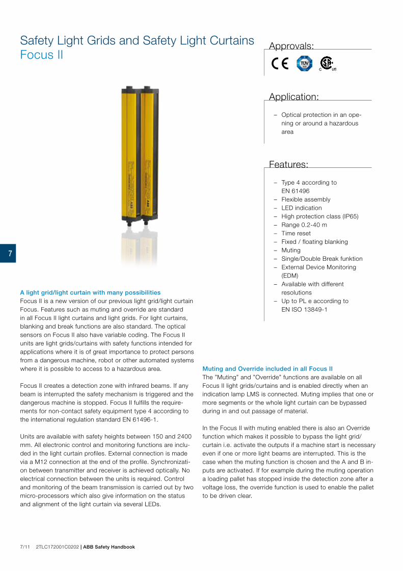
A light grid/light curtain with many possibilities Focus II is a new version of our previous light grid/light curtain Focus. Features such as muting and override are standard in all Focus II light curtains and light grids. For light curtains, blanking and break functions are also standard. The optical sensors on Focus II also have variable coding. The Focus II units are light grids/curtains with safety functions intended for applications where it is of great importance to protect persons from a dangerous machine, robot or other automated systems where it is possible to access to a hazardous area.
Focus II creates a detection zone with infrared beams. If any beam is interrupted the safety mechanism is triggered and the dangerous machine is stopped. Focus II fulfills the require-ments for non-contact safety equipment type 4 according to the international regulation standard EN 61496-1.
Units are available with safety heights between 150 and 2400 mm. All electronic control and monitoring functions are inclu-ded in the light curtain profiles. External connection is made via a M12 connection at the end of the profile. Synchronizati-on between transmitter and receiver is achieved optically. No electrical connection between the units is required. Control and monitoring of the beam transmission is carried out by two micro-processors which also give information on the status and alignment of the light curtain via several LEDs.
Muting and Override included in all Focus IIThe ”Muting” and ”Override” functions are available on all Focus II light grids/curtains and is enabled directly when an indication lamp LMS is connected. Muting implies that one or more segments or the whole light curtain can be bypassed during in and out passage of material.
In the Focus II with muting enabled there is also an Override function which makes it possible to bypass the light grid/curtain i.e. activate the outputs if a machine start is necessary even if one or more light beams are interrupted. This is the case when the muting function is chosen and the A and B in-puts are activated. If for example during the muting operation a loading pallet has stopped inside the detection zone after a voltage loss, the override function is used to enable the pallet to be driven clear.
Safety Light Grids and Safety Light CurtainsFocus II
Approvals:
Application:
– Optical protection in an ope-ning or around a hazardous area
Features:
– Type 4 according to EN 61496
– Flexible assembly – LED indication – High protection class (IP65) – Range 0.2-40 m – Time reset – Fixed / floating blanking – Muting – Single/Double Break funktion – External Device Monitoring
(EDM) – Available with different
resolutions – Up to PL e according to
EN ISO 13849-1

ABB Safety Handbook | 2TLC172001C0202 7/12
7
BlankingIt is also possible to obtain the Focus II light curtains with blanking. Floating blanking is a tolerance setting that makes it possible to ’disconnect’ a defined number of beams from the detection zone. The object is then free to move in the detec-tion zone without the safety function being triggered. Other tolerance settings allows less movment of the interfering object. Blanking may require an additional fixed guard and may require additonal minimum distance to the dangerous movment.
Safety outputs OSSD1 and OSSD2Focus II has two PNP outputs - OSSD1 and OSSD2. If the load to be switched is alternating current or requires a higher current than 500 mA then one should use a safety relay e.g. RT9, Pluto PLC or the FRM-1 unit (converts the outputs to relay contacts) from ABB Jokab Safety. The FMC-Tina and Tina 10A/10B/10C converts the outputs to a dynamic signal for connection to Pluto or Vital. Pluto can also work directly with the OSSD-outputs.
Single/Double Break functionThis function is used for presses when the operator prepares or picks out a detail. With the Single Break function the light curtain allows operation after entry and withdrawal out of the curtain. Similarly, the Double Break function allows operation after entry and withdrawal twice.
External Device Monitoring (EDM)In all light grids and light curtains an EDM function is available which allows Focus II to test if the external control element responds correctly. A test channel is connected through the respective contactor, in order to detect any faults and thereby prevent a reset.
ResetOn every Focus II there are inputs for reset. The reset option is chosen through dual switches in the Focus II receiver. At delivery, Focus II is set to automatic reset.
– Automatic reset – When the detection zone is free the outputs are closed directly. (Setting when delivered).
– Manual reset – When the light field detection zone is free, the reset button has been actuated before the outputs are activated.
– Time reset – To reset the Focus II a pre-reset button must first be actuated and afterwards within 8 seconds a reset button outside the hazardous area must be actuated.
Focus II light gridStandard: – Muting (bypassing) of one, two, three or four beams – Supervised output for muting lamp – Override – Manually supervised or automatic reset – Time-reset. – EDM
Option: – Light grids for tough environments with parallel beams of
light for improved reliability.
Focus II light curtainStandard: – Muting (bypassing) partly or completely – Supervised output for muting lamp – Override – Manually supervised or automatic reset – Time-reset – Blanking – Single/Double Break – EDM
With the switches at the bottom of Focus II you can choose the function you desire.
JSM 662TLA022090R1300JSM 66 Bracket for Focus II

7/13 2TLC172001C0202 | ABB Safety Handbook
7
Standard ¤ With Tina 10A/10B/10C or FMC-Tina
NOTE! For ordering data and article number see the product list. For more information see the manual on our home page.
Focus ll light curtain/grid, Type 4 (FII-4) Summary
Model name FII-4-14-zzzz FII-4-30-zzzz FII-4-K4-zzzz FII-4-K3-800 FII-4-K2-500 FII-4-K4-zzzz D FII-4-K3-800 D FII-4-K2-500 D FII-4-K2C-zzzz FII-4-K2C-800 FII-4-K1C-500
Resolution 14 30
Beam distance 300 400 400 500 300 400 400 500 300 400 400 500
Height (mm=zzzz)
150
300
450
600
750
900
1050
1200
1350
1500
1650
1800
1950
2100
2250
2400
150
300
450
600
750
900
1050
1200
1350
1500
1650
1800
1950
2100
2250
2400
900 1200 800 500 900 1200 800 500 900 1200 800 500
Range (m) SR LR
0.2-3
3-6
0.2-7
7-14
0.5-20
20-40
0.5-20
20-40
0.5-20
20-40
0.5-20
20-40
0.5-20
20-40
0.5-20
20-40
0.5-7 0.5-8 0.5-12
Reaction time off (ms) 18-103 14-47 13 13 13 13 13 13 13 13 13
Reaction time on (ms) 138-104 141-119 142 142 142 142 142 142 142 142 142
Manual reset
Automatic reset
Pre reset
Muting inputs
Muting lamp supervision
Override
Muting T/L/X
Blanking 3 types
Single/Double break
EDM
Dyn. Adaption to Vital/Pluto ¤ ¤ ¤ ¤ ¤ ¤ ¤ ¤ ¤ ¤ ¤

ABB Safety Handbook | 2TLC172001C0202 7/14
7
Model name FII-4-14-zzzz FII-4-30-zzzz FII-4-K4-zzzz FII-4-K3-800 FII-4-K2-500 FII-4-K4-zzzz D FII-4-K3-800 D FII-4-K2-500 D FII-4-K2C-zzzz FII-4-K2C-800 FII-4-K1C-500
Resolution 14 30
Beam distance 300 400 400 500 300 400 400 500 300 400 400 500
Height (mm=zzzz)
150
300
450
600
750
900
1050
1200
1350
1500
1650
1800
1950
2100
2250
2400
150
300
450
600
750
900
1050
1200
1350
1500
1650
1800
1950
2100
2250
2400
900 1200 800 500 900 1200 800 500 900 1200 800 500
Range (m) SR LR
0.2-3
3-6
0.2-7
7-14
0.5-20
20-40
0.5-20
20-40
0.5-20
20-40
0.5-20
20-40
0.5-20
20-40
0.5-20
20-40
0.5-7 0.5-8 0.5-12
Reaction time off (ms) 18-103 14-47 13 13 13 13 13 13 13 13 13
Reaction time on (ms) 138-104 141-119 142 142 142 142 142 142 142 142 142
Manual reset
Automatic reset
Pre reset
Muting inputs
Muting lamp supervision
Override
Muting T/L/X
Blanking 3 types
Single/Double break
EDM
Dyn. Adaption to Vital/Pluto ¤ ¤ ¤ ¤ ¤ ¤ ¤ ¤ ¤ ¤ ¤
7/15 2TLC172001C0202 | ABB Safety Handbook
7
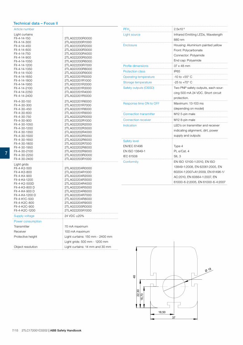
Technical data – Focus ll
Article number
Light curtainsFII-4-14-150 2TLA022200R0000FII-4-14-300 2TLA022200R1000FII-4-14-450 2TLA022200R2000FII-4-14-600 2TLA022200R3000FII-4-14-750 2TLA022200R4000FII-4-14-900 2TLA022200R5000FII-4-14-1050 2TLA022200R6000FII-4-14-1200 2TLA022200R7000FII-4-14-1350 2TLA022200R8000FII-4-14-1500 2TLA022200R9000FII-4-14-1650 2TLA022201R0000FII-4-14-1800 2TLA022201R1000FII-4-14-1950 2TLA022201R2000FII-4-14-2100 2TLA022201R3000FII-4-14-2250 2TLA022201R4000FII-4-14-2400 2TLA022201R5000
FII-4-30-150 2TLA022201R6000FII-4-30-300 2TLA022201R7000FII-4-30-450 2TLA022201R8000FII-4-30-600 2TLA022201R9000FII-4-30-750 2TLA022202R0000FII-4-30-900 2TLA022202R1000FII-4-30-1050 2TLA022202R2000FII-4-30-1200 2TLA022202R3000FII-4-30-1350 2TLA022202R4000FII-4-30-1500 2TLA022202R5000FII-4-30-1650 2TLA022202R6000FII-4-30-1800 2TLA022202R7000FII-4-30-1950 2TLA022202R8000FII-4-30-2100 2TLA022202R9000FII-4-30-2250 2TLA022203R0000FII-4-30-2400 2TLA022203R1000
Light gridsFII-4-K2-500 2TLA022204R0000FII-4-K3-800 2TLA022204R1000FII-4-K4-900 2TLA022204R2000FII-4-K4-1200 2TLA022204R3000FII-4-K2-500D 2TLA022204R4000FII-4-K3-800 D 2TLA022204R5000FII-4-K4-900 D 2TLA022204R6000FII-4-K4-1200 D 2TLA022204R7000FII-4-K1C-500 2TLA022204R8000FII-4-K2C-800 2TLA022204R9000FII-4-K2C-900 2TLA022205R0000FII-4-K2C-1200 2TLA022205R1000
Supply voltage 24 VDC ±20%
Power consumption
Transmitter
Receiver
Protective height
Object resolution
70 mA maximum
100 mA maximum
Light curtains: 150 mm - 2400 mm
Light grids: 500 mm - 1200 mm
Light curtains: 14 mm and 30 mm
22,3
0
18,50
37
48
16,7
0
Ø 18
PFHD 2.5x10⁻⁹
Light source Infrared Emitting LEDs, Wavelength
880 nm
Enclosure Housing: Aluminium painted yellow
Front: Polycarbonate
Connector: Polyamide
End cap: Polyamide
Profile dimensions 37 x 48 mm
Protection class IP65
Operating temperature -10 to +55° C
Storage temperature -25 to +70° C
Safety outputs (OSSD) Two PNP safety outputs, each sour-
cing 500 mA 24 VDC. Short circuit
protection.
Response time ON to OFF Maximum: 13-103 ms
(depending on model)
Connection transmitter M12 5-pin male
Connection receiver M12 8-pin male
Indication LED´s on transmitter and receiver
indicating alignment, dirt, power
supply and outputs
Safety level
EN/IEC 61496
EN ISO 13849-1
IEC 61508
Type 4
PL e/Cat. 4
SIL 3
Conformity EN ISO 12100-1:2010, EN ISO
13849-1:2008, EN 62061:2005, EN
60204-1:2007+A1:2009, EN 61496-1/
AC:2010, EN 60664-1:2007, EN
61000-6-2:2005, EN 61000-6-4:2007

ABB Safety Handbook | 2TLC172001C0202 7/16
7
Focusll
Focusll
Focus MF-LFocus MF-T
Built-in muting for Focus II is available in three ways: – Pre-made muting units MF-T and MF-L, which have integral
photocells. – Connection of muting sensors via a FMC. – Separate connection of muting sensors (Mute R) directly to
the Focus II receiver unit.
Muting-lampTo the Focus II receiver unit it is also possible to directly con-nect a external muting-lamp. It is also possible to connect the muting-lamp via a FMC. During bypassing the muting-lamp is lit. Bypassing is only possible if the muting-lamp is functioning or a resistor of 220 Ohm is used in its place.
MF-T and MF-L are muting units with integrated photocells built into a aluminum profile. They work with all Focus II light grid and curtain. No additional sensors are required because the muting units contain the required components. MF-T/MF-L is connected between the Focus II and the supervising unit (e.g safety relay, safety PLC). The cable between the Focus II and MF-T/MF-L is included with the muting unit.
Muting with MF-T and MF-L units
MF-T The muting unit MF-T consist of a transmitter unit and a receiver unit with four photocells A1, B1, B2 and A2. A1 and A2 are connected in parallell and B1 and B2 connected in parallell. In this way the unit is configured for installations where material is transported into and/or out of a hazardous area.
MF-L The muting unit MF-L consist of a transmitter unit and a receiver unit with two photocells A1 and B1. The A1 and B1 sensor are actuated before the material is transported through the light grid/curtain. The light grid is an active part in upholding the muting function once A1 and B1 have been passed by the material. The light grid/curtain is being bypassed just as long as the material exiting. Unit MF-L is primarily intended for material transport out of a hazardous area.
MF-T ReflexThe muting unit MF-T Reflex consist of a transmitter/receiver side and a reflector unit. The active side contains four transmit-ters/receivers photocells. The MF-T Reflex works as the MF-T with a limited range (6m). These units, together with a light grid with one active and one passive side provides a good solution were electrical connections is only necessary on one side!
MF-L ReflexThe muting unit MF-L Reflex consist of a transmitter/receiver unit and a reflector unit. The active side contains two transmit-ters/receivers photocells. The MF-L Reflex works as the MF-L with a limited range (6m). These units, together with a light grid with one active and one passive side provides a good solution were electrical connections is only necessary on one side!
M12 connection between Focus II and MF-T Reflex
out fromhazardous area
MF-L
out/in fromhazardous area
MF-T
Focus IIMuting (bypassing)
Focus II muting types – T-muting. Four NO muting sensors are used in two pairs
(OR function), allowing bi-directional transport of material. Maximum muting time is 600 s. Muting A and Muting B need an activation time difference of 30 ms.
– L-muting. Two NO muting sensors works together with the light protection, allowing transport out from the hazardous area. Maximum muting time is 600 s. Muting A and Muting B need a activation time difference of 30 ms.
– X-muting. One NO and one NC muting sensor is like a cross through the light protection, allowing bi-directional transport of material. An alternative X-muting (only on Fo-cus Light beams) with 2 NO muting sensor is also possi-ble, but then with the condition of a 30 ms activation time difference on the muting sensors. Both solutions gives an infinite muting time.

7/17 2TLC172001C0202 | ABB Safety Handbook
7
Focus IIMuting with MF-T and MF-L
A solution with Focus Muting unit MF-T with integrated muting sensors.
A solution with Focus Muting unit MF-L with integrated muting sensors
NOTE! The muting sensors A and B must be placed so that the sensor A is always activated at least 30 ms before sensor B.
D: indicates the minimum length of the material that is to actuate the muting sen-sors that must be maintained during the passage through the light grid/curtain. d2: indicates the measurement between the two/four pre-assembled muting sen-sors within the MF-L and MF-T.
This solution shall only be used for movement out from a hazardous area.
Possible direction of movement - in/out of hazardous area.
A1 B1
d2 = 260 mm D = 300 mm
Hazardous area
Hazardous area

ABB Safety Handbook | 2TLC172001C0202 7/18
7
10...30 VDCPNPdark-on output
FSTR 1
1
42
3Rl
10...30 VDCPNP
1
2
3
4
Muting sensors – Mute R Retro-reflective with polarizing filters
Technical dataArticle number
Mute R (FSTR-1) 2TLA022044R0000Output PNP, dark onConnection Connector M12 Range adjustment YesRange 0.15... 2.5 m (with reflector FZR 1)
0.15...5m (with reflector FZR 2A) Light source Visible-red, 660 nm, pulsed with
polarizing filterSupply voltage 10...30 VDCAllowable ripple ± 10% of UsCurrent consumption (without load)
<15 mA
Max. load current 100 mAResidual voltage <1.6 VMax. switching frequency 1000 HzProtection class IP67Temperature(operating and storage) -25 to +65° CWeight approx. 15 gAll technical data at 25˚ C and 24V.
1 (+) Supply voltage 10...30 V4 Dark-on output3 (-) Supply voltage
Dark-on outputThe output is activated when an object interrupts the light.
Connector M12
1. Connector M122. Range adjustment and
function indicator3. Plastic housing
PNP output
Dark-on output
FZR 1 2TLA022044R0100Reflector Ø 80 mm incl.screw MC6S M5 x 14 + Locking nut M5.
FZR 2A 2TLA022044R0400Reflector 100 x 100 mm incl. screw MC6S M5 x 14 + Lo-cking nut M5.
Approvals:
Features:
– Range adjustable – Light reserve warning indictor – Transistor output, PNP – 1000 Hz switching frequency – Short-circuit protection,
reverse polarity protection and power-up output suppression
– Connector M12 – EMC tested according to
IEC 801 and EN50081-1/EN 50082-2
max
.15
7/19 2TLC172001C0202 | ABB Safety Handbook
7
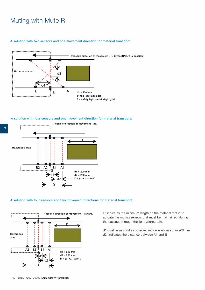
Muting with Mute R
A solution with two sensors and one movement direction for material transport:
A solution with four sensors and two movement directions for material transport:
D: indicates the minimum length on the material that is to actuate the muting sensors that must be maintained during the passage through the light grid/curtain.
d1 must be as short as possible, and definitely less than 200 mmd2: indicates the distance between A1 and B1
A1 B1 S
A2 B2
d2
D
D
d1 d1 < 200mm d2 > 250mm D=(d1x2)+d2+40
A solution with four sensors and one movement direction for material transport:
Possible direction of movement - IN.
Hazardous area
A1 B1 S
B2 A2
d2
D
D
d1 d1 < 200mm d2 > 250mm D=(d1x2)+(d2x2)+40
Possible direction of movement - IN/OUT.
Hazardous area
A S B
d3
d4
Possible direction of movement - IN (Even IN/OUT is possible)
Hazardous area
d3 > 500 mmd4 the least possibleS = safety light curtain/light grid
d1 > 200 mmd2 > 250 mmD = (d1x2)+d2+40
d1 > 200 mmd2 > 250 mmD = (d1x2)+d2+40

ABB Safety Handbook | 2TLC172001C0202 7/20
7
Various FMC, FMI, FRM- versions and Tina unitsThe Tina-versions have dynamic safety outputs for Vital/Pluto.
Muting accessories FMC and FMI units
Model Description
FMC-1(2) with connectors for muting sensors (A+B),
reset, power off and muting lamp (R) and
muting lamp (M).
FMI-1A with muting lamp only.
FMI-1B with reset, power off and muting lamp.
FMI-1C with reset and power off.
FMI-1D with reset, power off and internal resistor for
the muting lamp.
FMI-1E as pre reset connected to connector A (A2)
on FMC-1(2) (Tina).
FMI-1G with reset, and internal resistor for the muting
lamp.
FMC-1
(2) Tina
same as FMC-1(2) but connected to Vital or
Pluto.
Tina 10A adaptor unit for connecting Focus II to Vital
or Pluto.
Tina 10B simplified FMC-1(2) Tina including only the
connector (R).
Tina 10C simplified FMC-1(2) Tina including only power
supply on con.no.3.
FRM-1A translates the two OSSD outputs to relay
outputs (and power supply).
JS SP-1 protection plug for not used connectors.
JS AP-1 adaptor for FMC units to use instead of
FMI-1B or -1D on the (R) connector including
muting resistor.
Approvals:
Application:
– FMC: Muting connection box – FMI: Muting Indicator
Features:
– Small – Easy to connect

7/21 2TLC172001C0202 | ABB Safety Handbook
7
Connection of Focus II and muting components as FMC and FMI
Ex 1. Connection of light curtain with connection block FMC-1, test/reset button and switch for supply voltage placed in (by) the control cabinet.
Ex 2. Connection of light curtain with connection block FMC-1. The Reset unit FMI must be placed out of reach from the hazardous area.
Connection of Focus II and muting components directly to the control cabinet
– The TEST /RESET button shall be placed so the opera-tor can see the protected area during reset, testing, and bypassing. It shall not be possible to reach the button from within the hazardous area.
– The LMS lamp for indication of muting and bypassing shall be placed so that it can be seen from all directions from where it is possible to access the hazardous area.
– If photocells are used as muting sensors then the sensor receivers shall be assembled on the light curtain´s transmit-ter side to minimise the interference risk.
– The system is protected against dangerous functions caused by damage on the transmitter cable and/or the receiver cable. However, we recommend that the cables be protected so that physical damage to them can be mini-mised.
Muting lamp
Connection unit FMC-1
Muting photocells
Cabinet
Power ”off”
Test/Reset
Muting lamp
Test & reset buttons
Protectcables
Cable to lampSupplycable
Muting cable
FR-cableFT-cable
FMI
Muting photocells
Muting lamp
Connection unit FMC-1
Cabinet
Power ”off”
Reset
Muting with FMI and FMC

ABB Safety Handbook | 2TLC172001C0202 7/22
7
20°
Ø22
0R5,50
260
170
10
Bracket for MFII mirrors. 2 pcs needed for each mirror.
JSM 70, 2TLA040001R1500. Plate for easy adjustment on uneven floors.
Technical data – Mirrors
Type Article NoHeight mirror glass, mm
Height total, mm
MFII-300 2TLA022041R0200 356 361
MFII-450 2TLA022041R0300 506 511
MFII-600 2TLA022041R0400 653 658
MFII-750 2TLA022041R0500 796 801
MFII-900 2TLA022041R0700 953 958
MFII-1050 2TLA022041R1200 1103 1108
MFII-1200 2TLA022041R0800 1253 1258
MFII-1350 2TLA022041R1300 1403 1408
MFII-1500 2TLA022041R0900 1546 1551
MFII-1650 2TLA022041R1000 1703 1708
Bracket for
MFII mirrors.
2TLA022041R2000
Accessories
Adjustment plate
MFII mirrors for light curtain

7/23 2TLC172001C0202 | ABB Safety Handbook
7
Bjorn is a very stable and flexible stand system in which Focus II safety light grids/curtains and mirrors are mounted in the stand. The fixings for the mirrors in the stand can be turned to provide either vertical or horizontal angles. The robust material of the Bjorn protects Focus II units from direct collisions, and thus prevents unnecessary material damage and halts in production.
Light protection standBjorn
M3
M2
M4
M1
Receiver
Transmitter
Bjorn N2
Bjorn H2horizontal
Bjorn V2vertical
Application:
– Protects light curtain, light grids and mirror
Features:
– Robust – Adjustable

ABB Safety Handbook | 2TLC172001C0202 7/24
7
15
43
181
144
230
190
Bjorn N2 2TLA022041R4500
Bjorn N3 2TLA022041R4600
Bjorn N4-12TLA022041R4700
Bjorn N4-2 2TLA022041R4700
Bjorn N5 2TLA022041R4900
Bjorn H2 2TLA022041R4000
Bjorn H3 2TLA022041R4200
Bjorn H4-12TLA022041R4300
Bjorn H4-22TLA022041R4400
Bjorn V2 2TLA022041R4100
Technical data – Bjorn
Article number
Bjorn H2
Bjorn V2
Bjorn H3
Bjorn H4-1
Bjorn H4-2
Bjorn N2
Bjorn N3
Bjorn N4-1
Bjorn N4-2
Bjorn N5
H = Horizontal reflection
V = Vertical reflection
N = For the light guard unit
2TLA022041R4000
2TLA022041R4100
2TLA022041R4200
2TLA022041R4300
2TLA022041R4400
2TLA022041R4500
2TLA022041R4600
2TLA022041R4700
2TLA022041R4800
2TLA022041R4900
Colour Yellow powder-coated (RAL 1018)
Material 3 mm steel
Dimensions
Cross section
Foot
146 mm x 130 mm
230 mm x 190 mm
Weight
N2
H2, V2
N3
H3, N4-1
H4-1
N4-2:
H4-2
N5
14 kg/piece
15 kg/piece
17 kg/piece
18 kg/piece
20 kg/piece
22 kg/piece
24 kg/piece
27 kg/piece
Mirror reduction ~10 % per mirror
7/25 2TLC172001C0202 | ABB Safety Handbook
7
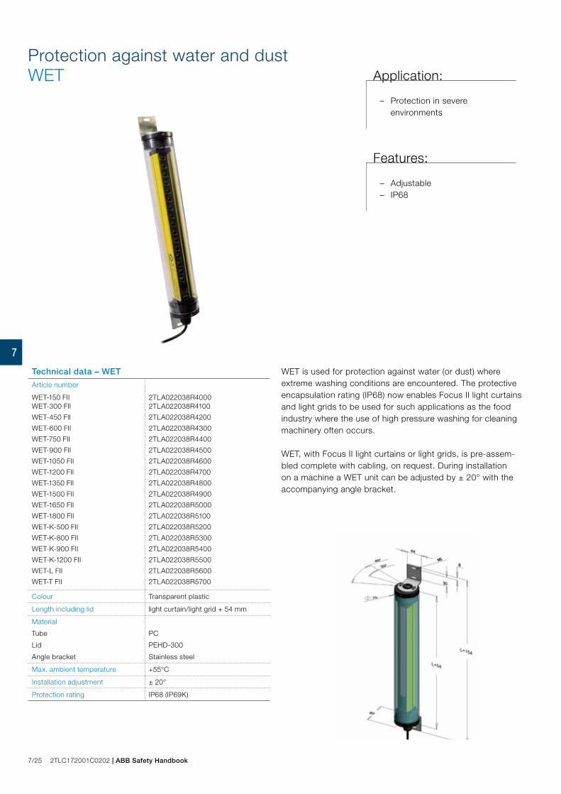
Protection against water and dustWET
WET is used for protection against water (or dust) where extreme washing conditions are encountered. The protective encapsulation rating (IP68) now enables Focus II light curtains and light grids to be used for such applications as the food industry where the use of high pressure washing for cleaning machinery often occurs.
WET, with Focus II light curtains or light grids, is pre-assem-bled complete with cabling, on request. During installation on a machine a WET unit can be adjusted by ± 20° with the accompanying angle bracket.
Technical data – WET
Article number
WET-150 FII 2TLA022038R4000WET-300 FII 2TLA022038R4100
WET-450 FII 2TLA022038R4200
WET-600 FII 2TLA022038R4300
WET-750 FII 2TLA022038R4400
WET-900 FII 2TLA022038R4500
WET-1050 FII 2TLA022038R4600
WET-1200 FII 2TLA022038R4700
WET-1350 FII 2TLA022038R4800
WET-1500 FII 2TLA022038R4900
WET-1650 FII 2TLA022038R5000
WET-1800 FII 2TLA022038R5100
WET-K-500 FII 2TLA022038R5200
WET-K-800 FII 2TLA022038R5300
WET-K-900 FII 2TLA022038R5400
WET-K-1200 FII 2TLA022038R5500
WET-L FII 2TLA022038R5600
WET-T FII 2TLA022038R5700
Colour Transparent plastic
Length including lid light curtain/light grid + 54 mm
Material
Tube
Lid
Angle bracket
PC
PEHD-300
Stainless steel
Max. ambient temperature +55°C
Installation adjustment ± 20°
Protection rating IP68 (IP69K)
Application:
– Protection in severe environments
Features:
– Adjustable – IP68
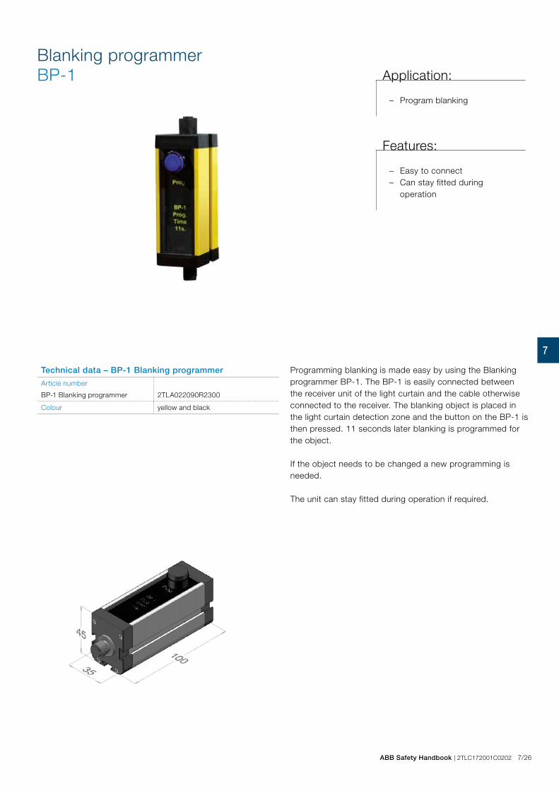
ABB Safety Handbook | 2TLC172001C0202 7/26
7
Blanking programmer BP-1
Technical data – BP-1 Blanking programmer
Article number
BP-1 Blanking programmer 2TLA022090R2300
Colour yellow and black
Programming blanking is made easy by using the Blanking programmer BP-1. The BP-1 is easily connected between the receiver unit of the light curtain and the cable otherwise connected to the receiver. The blanking object is placed in the light curtain detection zone and the button on the BP-1 is then pressed. 11 seconds later blanking is programmed for the object.
If the object needs to be changed a new programming is needed.
The unit can stay fitted during operation if required.
Application:
– Program blanking
Features:
– Easy to connect – Can stay fitted during
operation

7/27 2TLC172001C0202 | ABB Safety Handbook
7
Connection examples
HR7000E-01 Focus II - Connection with pre-reset function
HR7000C-01 Focus II - Connection without and with muting function

ABB Safety Handbook | 2TLC172001C0202 7/28
7
Connection examples
HR7000G-01 Focus II - Connection with MF-T/MF-L units
HR7000F-01 Focus II - Connection with muting to safety relay

7/29 2TLC172001C0202 | ABB Safety Handbook
7
Connection examples
FMC - Connection possibilities
HR7000H-01 Focus II - Connection with FMC/Tina Interface

ABB Safety Handbook | 2TLC172001C0202 7/30
7
Connection examples
HR7000K-01 FMC-1 or FMC-1 Tina connected with Pre-Reset
HR7000J-01 FMC-1 or FMC-1 Tina with muting sensors and reset unit
7/31 2TLC172001C0202 | ABB Safety Handbook
7
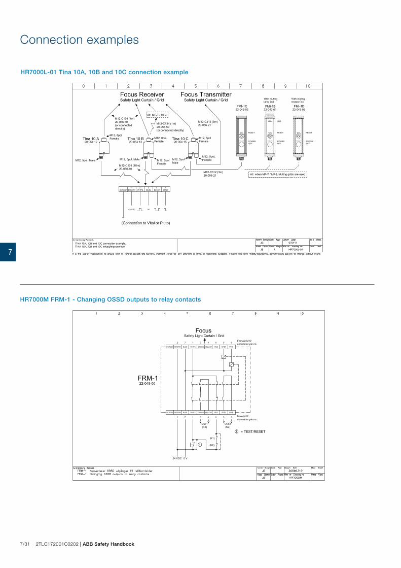
Connection examples
HR7000M FRM-1 - Changing OSSD outputs to relay contacts
HR7000L-01 Tina 10A, 10B and 10C connection example

ABB Safety Handbook | 2TLC172001C0202 7/32
7
Connection examples
HR7000P Cable connection example
HR7000O-01 Connection example FMC/FMI

7/33 2TLC172001C0202 | ABB Safety Handbook
7
Connection examples
HR7000S Focus II; Muting with the aid of Pluto, FMC and a transfer cable
HR7000Q Cable connection example

ABB Safety Handbook | 2TLC172001C0202 7/34
7
* *
10 m35 m
10 m35 m
Transmitter 1 Receiver 1 Spot T Spot R
Transmitter 2 Receiver 2 Spot T Spot R
Coded pulse transmission
Coded pulse transmission
24VDC This supply doesnot need to be the same as connected to the Vital.
Vital Safety controller can accomodate up to 6 Spot systems.
A light beam for the highest safety levelThe light beam is available in two versions Spot 10 for distan-ces up to 10 m and Spot 35 for up to 35 m . The light beams can be mounted at different heights and be angled around a machine using our mirrors and brackets.
Spot and Vital/Pluto in combination fulfils the requirements for PL e according to EN ISO 13849-1 and type 4 according to EN 61496. Several light beams, Eden sensors and emergency stops can be connected in series achieving the high safety level for the safety circuit. A number of solutions for bypassing of light beams for material transport are available.
For indication there are LED´s on the transmitter and on the receiver which indicate ’contact’ between transmitter and re-ceiver and safety status. The ’contact’ information is available via the light beam receiver connection cables.
FunctionThe Spot light beam is supervised by the Vital safety controller or by the Pluto safety-PLC. A unique coded signal is sent out from the control unit to the transmitter (Spot T). The signal which comes back from the receiver (Spot R) is then compared in the Vital/Pluto. If the correct coded signal is received the Vital/Pluto switches the necessary safety output contacts to permit dangerous machine movements. Coding guarantees that no output signals can be produced by light from other sources, interference or faults in components in the transmitter or receiver. The light beam is dynamically
Coded pulse transmission
*
Safety Light BeamSpot
Approvals:
Application:
– Photoelectric guarding of an entrance or around a risk area
Features:
– Safety level Type 4 according to EN 61496
– Versatile mounting – LED indication – IP67 – 10 m or 35 m range – Bypassing possibility – Light beam, emergency
stop and Eden in the same safety circuit together with Vital/Pluto achieves PL e according to EN SO 13849-1
supervised which means that if the signal stops pulsating at the correct frequency it is immediately detected. By means of coding, the dynamic signal can pass between up to 6 pairs of transmitters and receivers, with only one pair needing to be electrically connected to a Vital.
TÜVNORD

7/35 2TLC172001C0202 | ABB Safety Handbook
7
R
T
Spot Mounting and alignment
Safety distanceThe basic principle is that dangerous machine movements should be stopped before a person reaches the dangerous area, which should be at least 850 mm from the light beams. When determining the correct safety distance the stopping time of the machine and the risk level must be taken into ac-count (see also EN ISO 13855).
Accessories and MountingThe Spot light beam can be mounted using a variety of bra-ckets, posts and mirrors.
AlignmentWhen aligning the light beam, look towards the transmitter. In the lens will be seen a strong red light. When this light is seen from the receiver (via mirrors if fitted) the light beam is basi-cally aligned. The LED on the receiver is on when the receiver is aligned with the transmitter. By moving the transmitter up/down and left/right the best alignment can be found.
When vertically mounting, (as shown in the diagram) the receiver should be mounted above the transmitter as this will simplify the alignment and minimise the risk of extraneous light disturbance. In exceptional light disturbance environments the received light can be adjusted by a screw on the rear of the Spot 35 receiver. On Spot 10 this adjustment can be made on the transmitter.
Different sizes of mirrors, mounting brackets and profiles are available.
NOTE! Every mirror reduces the sensing distance of the beam by approx. 20%.
JSM64Pivot M18 bracket for Spot 10 or MUTE R (FSTR1) for example

ABB Safety Handbook | 2TLC172001C0202 7/36
7
Technical data - Spot
Article number
Spot 10 T/R
Spot 35 T/R
2TLA020009R0600
2TLA020009R0500
Safety level
EN/IEC 61496
EN ISO 13849-1
Type 4 with Vital/Pluto
PL e/Cat. 4
PFHD 1.14x10⁻⁸
Power supply 17 – 27 VDC, ripple ±10%
Current consumption
Transmitter
Receiver
< 25 mA
< 15 mA
Output currents
Info. output
Dynamic signal out
10 mA max.
30 mA max.
Light source Red visible light, 660 nm, <±2°
Optical power
Spot 10
Spot 35
< 0.1 mW
< 0.2 mW
LED indication
Green LED on transmitter (power)
Green LED on receiver status
On
Flashing
Off
Power supply OK
Alignment OK, safety circuit closed
Alignment OK, earlier safety
circuit open
Beam interrupted, safety circuit open
Protection class IP67
Range
Spot 10
Spot 35
0 - 10 m
0 - 35 m
Range adjustment
Spot 10
Spot 35
Trim pot. on transmitter
Trim pot. on receiver
Installation
Spot 10
Spot 35
2xM18 nuts (provided)
Either via mounting holes in the
casing or with angle bracket JSM63
(provided)
Operating temperature range -25°C – +65°C
Cable connection M12 fixed connector
Casing Material
Spot 10
Spot 35
Steel housing with polyacryl lens
protection.
Polyamide housing with polyacryl
lens protection.
Colour
Spot 10
Spot 35
Steel grey
Yellow/black
Weight
Spot 10
Spot 35
2 x 21 g
2 x 100 g
Connections
Transmitter:
Brown (1)
White (2)
Blue (3)
Receiver:
Brown (1)
White (2)
Blue (3)
Black (4)
Grey (5)
+24 VDC
Dynamic signal in
0 VDC
+24 VDC
0 VDC
Dynamic signal out
Info output
24 VDC when LED is green or flas-
hing (tolerance -2 VDC)
0 VDC when LED is off (tolerance
+2 VDC)
Conformity EN ISO 12100:2010, EN ISO
13849-1:2008, EN 62061:2005,
EN 61508:2010, EN 60204-
1:2006+A1:2009, EN 61496-
1:2004+A1:2008, EN 60664-1:2007,
EN 61000-6-2:2005, EN 61000-6-
4:2007
Certifications TÜV Nord, cCSAus

7/37 2TLC172001C0202 | ABB Safety Handbook
7
Connection examples
HA3306D Vital 1 with 3 lightbeams Spot
HD3800A-01 Connection of Spot T/R to Vital1
*For more connection examples see chapters for Vital or Pluto

ABB Safety Handbook | 2TLC172001C0202 7/38
7
Related Documents